installation guide - the home depot guide sweat bee sweat bee 22 delta t corp all rights reserved...
TRANSCRIPT

2425 Merchant St., Lexington, KY 40511 1 (877) BIG-FANS | www.bigassfans.com
An ISO 9001:2008 certified company
www.bigasssolutions.com/patents
SWEAT BEE™
WWW.BIGASSFANS.COM ©2012 DELTA T CORP. ALL RIGHTS RESERVED 003489-01 REV. F JAN 2015
ContentsIntroductionThank You 2Technical Specifications 2Fan Diagram 2
Pre-InstallationParts and Hardware 3Preparing the Work Site 3
InstallationDirect Mount Installation 4Yoke Mount Installation 4Wall/Column Mount Installation 4Portable Base and Pedestal Installation 5Electrical Installation 6
TroubleshootingRecommended Troubleshooting Procedures 7
Preventive MaintenanceAnnual Preventive Maintenance 8General Preventive Maintenance 8Fan Blade Maintenance 8Maintenance Diagram 9
Startup ProceduresPre-Startup & Post-Startup Procedures 10
Warranty Return InstructionsReturn & Warranty Claim Form Instructions 12Warranty Claim Form 13Responsibility Agreement 14
READ AND SAVE THESE INSTRUCTIONS BEFORE INSTALLATIONWARNING: Electrical wiring must be done by qualified person(s) in accordance with all applicable codes and standards.
CAUTION: The installation of a Big Ass Fan must be in accordance with the requirements specified in this installation manual and with any additional requirements set forth by the national electric code (NEC) and all local codes.
CAUTION: When service or replacement of a component in the fan requires the removal or disconnection of a safety device, the safety device is to be reinstalled or remounted as previously installed.
CAUTION: Do not bend the blades when installing, adjusting, or cleaning the fan. Do not insert foreign objects between rotating blades.
CAUTION: Some fans can generate sound that could be hazardous to personnel. It is the responsibility of the user to measure the sound levels of the fan and/or system, determine the degree of personnel exposure, and comply with all applicable safety laws and requirements to protect personnel from excessive noise.
WARNING: In addition to normal dangers of rotating machinery, the fan can present additional hazards from the suction of pressure created at the fan inlet or discharge. Suction at the fan inlet can draw materials into the fan where they can become high velocity projectiles at the discharge and cause severe personal injury or death.
WARNING: Never operate the fan without the inlet and outlet cage guards in place. If these guards become defective or are removed, the power to the motor should be turned off and locked out until the cage guards have been replaced and inspected by the proper safety personnel.
WARNING: Some fans, fan components, and all motors operate at temperatures that could burn someone if they come in contact with them. If this potential hazard could exist in your installation, steps must be taken by the user to protect anyone from coming in contact with this equipment.
WARNING: No guarantee of any level of spark resistance is implied by spark resistant construction. Airstream material and debris or other system factors can also cause sparks.
INSTALLATION GUIDE
Sweat Bee™

SWEAT BEE™
WWW.BIGASSFANS.COM ©2012 DELTA T CORP. ALL RIGHTS RESERVED 003489-01 REV. F JAN 2015
2
Technical specificationsNote: A cord with a plug and switch is only provided with 18-inch fans.
Fan size 18” Fan size 30”Motor frame size 56 Motor frame size 56HMotor hp 1/3 hp Motor hp 1 hp
Full load current 6 A @ 100–125 V, 1 Ф 3 A @ 220–240 V, 1 Ф Full load current 3.7 A @ 200–220 V, 3 Ф
1.9 A @ 400–480 V, 3 ФMaximum speed 1725 RPM Maximum speed 1160 RPMMaximum operational temperature 104°F (40°C) Maximum operational
temperature 104°F (40°C)
Fan weight* 78 lbs (35.4 kg) Fan weight* 125 lbs (56.7 kg)
*Add an additional 9 lbs (4 kg) if using the wall/column mount with an 18-inch fan. Add an additional 15 lbs (6.8 kg) if using the wall/column mount with a 30-inch fan. Add an additional 31 lbs (14 kg), if using the portable base with an 18-inch fan.
Fan diagramNote: Fan setup may differ from the illustrations below.
A. Protective Cage and Housing. The steel cage guards and housing protect both the fan and users during operation.B. Handle. Provides support when transporting around the workspace. This part is only available with the portable base and pedestal
for 18-inch fans.C. Fan Motor (not shown). The fan motor powers the fan and rotates the fan blades. The motor is located on the
backside of the fan.D. Yoke. Supports the fan and allows for swivel.E. Wall/Column Mount (Optional). Supports the yoke and fan when mounting to a wall or column.F. Portable Base and Pedestal (Optional for 18-inch only). Elevates the fan and allows for transport around the
workspace.
IntroductionThank you and congratulations on your purchase of a Big Ass Fan, an efficient and cost-effective way to stay cool in the summer and warm in the winter. We’re ready to answer any questions at 1-877-BIG-FANS, or visit our Web site at www.bigassfans.com. This installation guide covers information for both 18-inch and 30-inch Sweat Bee™ fans.
Big Ass Fans has been the preeminent manufacturer of large-diameter, low-speed fans since 1999. With a worldwide presence and located in beautiful Lexington, KY, we research, design, and manufacture the most effective air movement solutions on the market. Our never-ending commitment to quality and innovation keeps us at the leading edge of a burgeoning industry. With an eye to helping customers satisfy their needs, and a strong sense of corporate responsibility to the community, Big Ass Fans has redefined the way business is done.
A
B
DF
A
D
E
SWEAT BEE™
3SWEAT BEE™
WWW.BIGASSFANS.COM ©2012 DELTA T CORP. ALL RIGHTS RESERVED 003489-01 REV. F JAN 2015
The fan is packaged to minimize possible damage during shipment. The freight carrier is responsible for delivering the fan in its original condition. The individual receiving the fan is responsible for inspecting the fan parts for any damage. If any damage is found, it should be noted on the bill of lading before the freight is accepted and the receiver must file a claim with the freight carrier.
If you are mounting the fan to a wall or column, some hardware used to secure the wall/column mount supports is customer-supplied. Big Ass Fans cannot provide specific installation details because of the wide variability of mounting surfaces, conditions, and fastening methods. Consult a structural engineer to determine the required hardware.
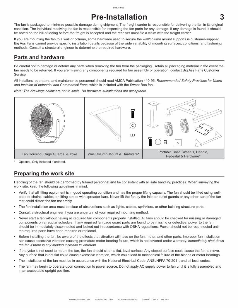
Parts and hardwareBe careful not to damage or deform any parts when removing the fan from the packaging. Retain all packaging material in the event the fan needs to be returned. If you are missing any components required for fan assembly or operation, contact Big Ass Fans Customer Service.
All installers, operators, and maintenance personnel should read AMCA Publication 410-96, Recommended Safety Practices for Users and Installer of Industrial and Commercial Fans, which is included with the Sweat Bee fan.
Note: The drawings below are not to scale. No hardware substitutions are acceptable.
Pre-Installation
* Optional. Only included if ordered.
Fan Housing, Cage Guards, & Yoke Wall/Column Mount & Hardware* Portable Base, Wheels, Handle, Pedestal & Hardware*
Preparing the work siteHandling of the fan should be performed by trained personnel and be consistent with all safe handling practices. When surveying the work site, keep the following guidelines in mind.
• Verify that all lifting equipment is in good operating condition and has the proper lifting capacity. The fan should be lifted using well-padded chains, cables, or lifting straps with spreader bars. Never lift the fan by the inlet or outlet guards or any other part of the fanthat could distort the fan assembly.
• The fan installation area must be clear of obstructions such as lights, cables, sprinklers, or other building structure parts.• Consult a structural engineer if you are uncertain of your required mounting method.• Never start a fan without having all required fan components properly installed. All fans should be checked for missing or damaged
components on a regular schedule. If any required fan cage guard parts are found to be missing or defective, power to the fanshould be immediately disconnected and locked out in accordance with OSHA regulations. Power should not be reconnected untilthe required parts have been repaired or replaced.
• Before installing the fan, be aware of the effects that vibration will have on the fan, motor, and other parts. Improper fan installationcan cause excessive vibration causing premature motor bearing failure, which is not covered under warranty. Immediately shut downthe fan if there is any sudden increase in vibration.
• If the yoke is not used to mount the fan, the fan should sit on a flat, level surface. Any sloped surface could cause the fan to move.Any surface that is not flat could cause excessive vibration, which could lead to mechanical failure of the blades or motor bearings.
• The installation of the fan must be in accordance with the National Electrical Code, ANSI/NFPA 70-2011, and all local codes.• The fan may begin to operate upon connection to power source. Do not apply AC supply power to fan until it is fully assembled and
in an acceptable upright position.

SWEAT BEE™
WWW.BIGASSFANS.COM ©2012 DELTA T CORP. ALL RIGHTS RESERVED 003489-01 REV. F JAN 2015
4 InstallationWARNING: Immediately disconnect the fan from power if there is any sudden increase in vibration!
CAUTION: Never make swivel and/or rotational adjustments while the fan is connected to power!
WARNING: The fan should never be operated with loose mounting or adjustment hardware!
Mechanical installationThe Sweat Bee™ is supplied standard with a direct mount. Optionally, a wall/column mount can be purchased to install the fan on a wall or vertical column. A yoke mount can be purchased to install the fan to an I-beam or bar joists. A pedestal can also be purchased to elevate the fan and provide mobility.
The Sweat Bee must be positioned in a location that is free of foreign objects that may interfere with the fan. The following instructions are merely a recommendation for mounting the Sweat Bee. Consult a structural engineer to determine the best method and hardware for mounting your fan.
Direct mount (standard)The fan yoke should be bolted to a horizontal structural member, such as a truss or I-beam. Do not directly bolt the fan yoke to a vertical beam or wall. The wall/column mount must be used in these applications. The fan can be swiveled up or down ±40° from the center.
To swivel the fan, disconnect the fan from power, and then loosen the two swivel adjustment bolts located on the sides of the fan housing. Reposition the fan and securely tighten the hardware. Ensure no strain is put on the electrical wiring for the motor when adjusting the fan position. Proceed to safety cable installation on page 6.
Yoke mount (optional)If installing the fan to an I-beam or bar joists with an extension tube, follow the installation instructions provided with the Yoke Mount kit.
Wall/Column mount (optional)The wall/column mount allows the Sweat Bee to be mounted to a wall or column. The mount must be bolted or welded to a vertical beam and mounted so that the fan is on the topside of the bracket, not hanging downward. The fan housing can be swiveled up or down ±40° from center and rotated 360° as long as it does not strain the electrical wiring for the motor.
To adjust the fan, disconnect the fan from power, and then loosen the appropriate hardware. Reposition the fan and securely tighten the hardware. Note: All hardware used to secure the wall/column mount to the wall or column is customer-supplied and must be of sufficient strength to support the weight of the fan. Proceed to safety cable installation on page 6.
WALL

SWEAT BEE™
5SWEAT BEE™
WWW.BIGASSFANS.COM ©2012 DELTA T CORP. ALL RIGHTS RESERVED 003489-01 REV. F JAN 2015
Portable Base and pedestal (optional for 18-inch fans only)The portable base and pedestal option includes a handle to allow for easy mobility around a workspace. Note: The portable base and pedestal are only available with 18-inch fans. To install the handle, portable base, and pedestal, do the following:
1. Install the handlePreassemble the handle by securing the bar to the brackets with the provided 5/16-18 x 3/4” bolts as shown on the right.On the fan, remove the hardware from the cage guards (front and rear) on the right side of the fan housing. Using the same hardware, install the bolts, lock washers, washers, handle, and weld nuts as shown below.
2. Install the wheelsAttach the wheels to the portable base by inserting the 1/2-13 x 3-1/2” hex head cap screw through the center of the wheel. Thread the 1/2” hex nut onto the screw approximately 1” (2.5 cm), and then insert the screw (attached to the wheel) into the hole on the fan base until it is tight. Screw the hex nut against the base, but do not overtighten. Repeat on the other wheel. Test the wheels to ensure they rotate freely.
3. Install pedestal and fanAttach the pedestal to the portable base with the (4) 3/8-16 x 1” bolts, (8) 3/8” washers, and (4) 3/8”-16 nylock nuts. Secure the fan yoke to the pedestal with the (4) 3/8-16 x 1-1/4” bolts, (8) 3/8” washers, adapter plate, (4) alignment aids, and (4) 3/8”-16 nylock nuts as shown. Securely tighten all hardware. Ensure the handle is installed on the same side as the wheels.
To swivel the fan, disconnect the fan from power, and then loosen the two swivel adjustment bolts located on the sides of the fan housing. Reposition the fan and securely tighten the hardware.
Installation (cont.)
Bar
Handle Brackets
BarBracket
Bracket
1
3
3
2

SWEAT BEE™
WWW.BIGASSFANS.COM ©2012 DELTA T CORP. ALL RIGHTS RESERVED 003489-01 REV. F JAN 2015
6Safety cable (customer-supplied) installationATTENTION: Do not connect any safety cable or chain to the fan housing on either end of the fan. Do not connect any safety cable or chain to an area near the blades where it could become entangled.
With every installation in which the fan is mounted above the floor, a safety cable or chain should be securely connected between the fan and the mounting structure to limit how far the fan could fall if the mounting hardware becomes loose. This safety feature should be installed by the user to prevent property damage, severe personal injury, death, and to comply with local codes. The cable or chain should not be any longer than needed to operate the fan properly and it should be strong enough to support a minimum of two (2) times the total weight of the fan assembly.
Electrical installationCAUTION: All wiring connections, inspection, and maintenance of any motor must be performed by a licensed electrician in accordance with the motor manufacturer’s recommendations, all electrical codes, and OSHA regulations. Failure to properly install, wire, or perform any maintenance to a motor can result in motor failure, property damage, injury, or death.
WARNING: Do not operate this fan from an ungrounded receptacle or use any device on the power cord that can defeat proper earth ground such as a plug adapter.
WARNING: Exercise caution and common sense when powering the fan. Do not connect the fan to a damaged or hazardous power source. Do not attempt to resolve electrical malfunctions or failures on your own. Contact Big Ass Fans if you have any questions regarding the electrical installation of this fan.
WARNING: The installation and usage of a Big Ass Fan must be in accordance with the requirements specified in this installation manual and with any additional requirements set forth by the national electric code (NEC) and all local codes. Code compliance is ultimately YOUR responsibility! Failure to comply with these codes could result in personal injury or property damage.
18-Inch Sweat Bee™. The 18-inch Sweat Bee is pre-wired for 115 volt, single-phase, 60 Hz, and includes a 12-ft cord with a switch and a 3-prong, grounded plug.
30-Inch Sweat Bee™. If the fan is a 30-inch Sweat Bee, the motor must be wired according to the schematic located on the motor itself. A licensed electrician must supply required electrical components and complete the wiring connections from the motor to an outside conduit box. Note: The cage guard must be removed to access the motor.
Power requirements
Fan size Motor size Supply circuit size Full load current Maximum ambient operating temperature
18 in. 1/3 hp 20 A @ 100–125 V, 1 Ф 6 A @ 100–125 V, 1 Ф3 A @ 220–240 V, 1 Ф
104°F (40°C)
30 in. 1 hp15 A @ 200–220, 3 Ф
20 A @ 400–480 V, 3 Ф3.7 A @ 200–220, 3 Ф
1.9 A @ 400–480 V, 3 Ф104°F (40°C)
Note: Assumes the use of an Inverse Time Circuit Breaker (I2t).
MotorThe fan comes standard with a Totally Enclosed (TEFC) or Open Drip Proof (ODP) motor. The installer (licensed electrician) is responsible for supplying all required electrical components and completing the electrical connections from the motor to the outside conduit box. Do not connect or operate a motor without reading the motor manufacturer’s instructions supplied with the fan.
Wiring connectionsAll wiring connections should be made for the proper voltage and phase displayed on the motor nameplate. Connections should follow the motor manufacturer’s recommendations shown in the wiring schematic, which is located on the outside of the motor, inside the motor conduit box, or on the motor nameplate. Reversing some wires might be necessary to reverse fan rotation if the blades do not rotate in the direction indicated by the arrow on the fan housing.
Disconnect switchAll fan motors should have an independent disconnect switch located in visual proximity to turn off electrical service to the fan motor. Disconnects must be locked out in accordance with OSHA “lock out-tag out” procedures any time inspection or maintenance is being performed on the fan or motor. The “lock out-tag out” procedures should be performed by authorized personnel. All disconnects should be sized in accordance with the latest NEC codes (National Electric Codes) and any local codes, and installed by a licensed electrician. “Slow blow” or “time delay” fuses or breakers should be used since the initial startup time for the fan motor can be up to 10 seconds.
Installation (cont.)

7SWEAT BEE™ SWEAT BEE™
WWW.BIGASSFANS.COM ©2012 DELTA T CORP. ALL RIGHTS RESERVED 003489-01 REV. F JAN 2015
TroubleshootingWARNING: Risk of fire, electric shock, or injury to persons during cleaning and user maintenance! Disconnect the appliance from the power supply before servicing.
WARNING: When service or replacement of a component in the fan requires the removal or disconnection of a safety device, the safety device is to be reinstalled or remounted as previously installed.
WARNING: Before servicing or cleaning the fan, switch off power at the service panel and lock the service disconnecting means to prevent power from being switched on accidentally. When the service disconnecting means cannot be locked, securely fasten a prominent warning device, such as a tag, to the service panel.
WARNING: Before inspecting or servicing the fan, be sure the fan is disconnected from power and that the blades have been carefully secured to prevent wind milling. If the operating conditions of the fan are to be changed (speed, temperature, etc.), consult Big Ass Fans to determine if the unit will operate safely in the new conditions.
WARNING: To avoid a potential “windmill” effect even when power is disconnected, the blades should be carefully secured to prevent any rotational turning before working on any parts of the fan that may move.
For questions about your product or customer service inquiries, please call our toll free number (877-BIG-FANS) or visit www.bigassfans.com/service.
Some issues can be resolved before requesting service. Review the below troubleshooting tips and procedures before contacting Customer Service for support.
Symptom Possible solution(s)
Airflow is inadequate.To be effective, the fan should be rotating in the direction of the arrow located on the fan housing. If the fan is not rotating in the correct direction, reversal of some wiring may be required. See the instructions provided on the motor.
The fan will not start.
Verify the following:• All wires are securely connected.• Supply power is adequate and functional.• All fuses or circuit breakers are not defective.
If the fan still does not start, contact Customer Service.
There is excessive vibration and/or noise during operation.
Excessive vibration can cause premature motor bearing failure that could lead to catastrophic failure of the fan. The most common causes of vibration are unbalanced blades, loose mechanical parts, motor imbalance, and foundation stiffness (not flat or level).
Verify the following:• The blades are not rubbing the inside of the fan housing, and are not worn or
corroded.• The blade set screws and taper-lock bushings are torqued to the specifications in the
table on the following page.• There is no accumulation of foreign material on the blades.• The mounting structure provides adequate support.• There are no loose mounting bolts, wheel set screws, or taper-lock hubs.
The motor is overheating.
Motor overheating can be caused by one or more of the following:• The voltage supplied to the motor is too high or too low.• Motor speed (RPM) is too high or the motor is defective.• The motor is wired incorrectly or there are loose wiring connections.
8SWEAT BEE™
WWW.BIGASSFANS.COM ©2012 DELTA T CORP. ALL RIGHTS RESERVED 003489-01 REV. F JAN 2015
Preventive MaintenanceWARNING: Risk of fire, electric shock, or injury to persons during cleaning and user maintenance! Disconnect the appliance from the power supply before servicing.
WARNING: When service or replacement of a component in the fan requires the removal or disconnection of a safety device, the safety device is to be reinstalled or remounted as previously installed.
WARNING: Before servicing or cleaning the fan, switch off power at the service panel and lock the service disconnecting means to prevent power from being switched on accidentally. When the service disconnecting means cannot be locked, securely fasten a prominent warning device, such as a tag, to the service panel.
WARNING: To avoid a potential “windmill” effect even when power is disconnected, the blades should be carefully secured to prevent any rotational turning before working on any parts of the fan that may move.
Please take a few moments to periodically perform the following preventive maintenance inspection on your fan to ensure its safe and efficient operation. The frequency of inspections must be determined by the user and is dependent upon the severity of the application, but it should never exceed a 12-month period. Prepare an inspection and maintenance schedule and adhere to it. If you have any questions, please contact Customer Service.
Annual preventive maintenanceThe following maintenance procedures are to be performed annually:• Check the fan hardware to make sure it is tight and shows no wear. If a screw is loose, discard it and replace it with a new screw.
Blade set screws or taper-lock bushings should be tightened to the torque values listed in the tables below.• Check the power cord and plug and motor wiring for damage.• Check the safety cable and mounting system to ensure there is no damage or wear.• Check the motor to ensure it is clean and dry. Refer to the motor manufacturer’s instructions for further information.• If using the portable base, ensure the wheels are secure and freely rotating.
General preventive maintenance• Keep the motor clean and dry.• Cleaning should be limited to exterior surfaces only. Follow the motor manufacturer’s instructions to clean the motor.• Most small motors have sealed bearings that are permanently lubricated for the life of the motor.• If the fan is not used daily, start the fan at least once every month and run for a few minutes.
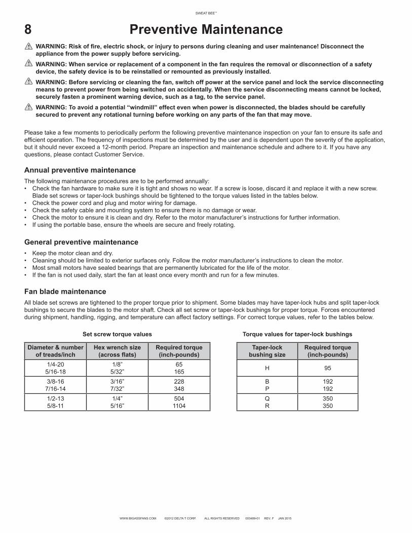
Fan blade maintenanceAll blade set screws are tightened to the proper torque prior to shipment. Some blades may have taper-lock hubs and split taper-lock bushings to secure the blades to the motor shaft. Check all set screw or taper-lock bushings for proper torque. Forces encountered during shipment, handling, rigging, and temperature can affect factory settings. For correct torque values, refer to the tables below.
Set screw torque values Torque values for taper-lock bushings
Diameter & number of treads/inch
Hex wrench size(across flats)
Required torque(inch-pounds)
Taper-lock bushing size
Required torque (inch-pounds)
1/4-205/16-18
1/8”5/32”
65165 H 95
3/8-167/16-14
3/16”7/32”
228348
BP
192192
1/2-135/8-11
1/4”5/16”
5041104
QR
350350
ATTENTION: Set screws should only be used once. If the set screws are loosened, they MUST be replaced. Use only knurled, cup-point set screws with a nylon locking patch.

9SWEAT BEE™ SWEAT BEE™
WWW.BIGASSFANS.COM ©2012 DELTA T CORP. ALL RIGHTS RESERVED 003489-01 REV. F JAN 2015
Maintenance DiagramThe diagrams below show an exploded Sweat Bee™ with the optional wall/column mount and the optional portable base and pedestal. The diagrams are intended only for reference. Your exact installation setup may differ. The fan blade design may slightly differ from the pictured.
Airflow
10SWEAT BEE™
WWW.BIGASSFANS.COM ©2012 DELTA T CORP. ALL RIGHTS RESERVED 003489-01 REV. F JAN 2015
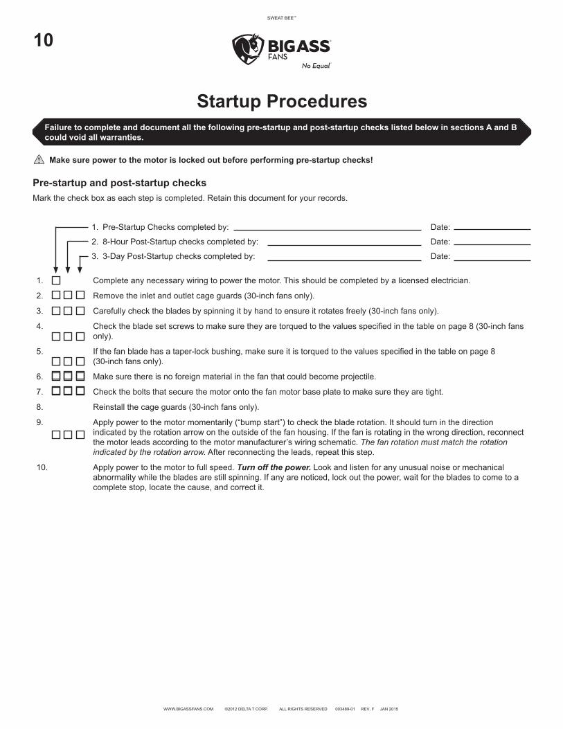
Startup Procedures Failure to complete and document all the following pre-startup and post-startup checks listed below in sections A and B could void all warranties.
Make sure power to the motor is locked out before performing pre-startup checks!
Pre-startup and post-startup checksMark the check box as each step is completed. Retain this document for your records.
1. Pre-Startup Checks completed by: Date:
2. 8-Hour Post-Startup checks completed by: Date:
3. 3-Day Post-Startup checks completed by: Date:
1. Complete any necessary wiring to power the motor. This should be completed by a licensed electrician.
2. Remove the inlet and outlet cage guards (30-inch fans only).
3. Carefully check the blades by spinning it by hand to ensure it rotates freely (30-inch fans only).
4. Check the blade set screws to make sure they are torqued to the values specified in the table on page 8 (30-inch fans only).
5. If the fan blade has a taper-lock bushing, make sure it is torqued to the values specified in the table on page 8 (30-inch fans only).
6. Make sure there is no foreign material in the fan that could become projectile.
7. Check the bolts that secure the motor onto the fan motor base plate to make sure they are tight.
8. Reinstall the cage guards (30-inch fans only).
9. Apply power to the motor momentarily (“bump start”) to check the blade rotation. It should turn in the direction indicated by the rotation arrow on the outside of the fan housing. If the fan is rotating in the wrong direction, reconnect the motor leads according to the motor manufacturer’s wiring schematic. The fan rotation must match the rotation indicated by the rotation arrow. After reconnecting the leads, repeat this step.
10. Apply power to the motor to full speed. Turn off the power. Look and listen for any unusual noise or mechanical abnormality while the blades are still spinning. If any are noticed, lock out the power, wait for the blades to come to a complete stop, locate the cause, and correct it.

SWEAT BEE™
Notes

12SWEAT BEE™
WWW.BIGASSFANS.COM ©2012 DELTA T CORP. ALL RIGHTS RESERVED 003489-01 REV. F JAN 2015
Replacement of products under warranty return instructionsIf you believe a part failed during normal operation and is covered under warranty, Big Ass Fans will ship a replacement part to you pursuant to your notice that you will be replacing the original part within 10 days. The replacement part will be shipped to you prior to our receipt of the item that failed, and prior to our evaluation of this part to determine the reasons for its failure and whether it is covered under warranty.
In order to evaluate the cause of the product failure, we will need you to return the original part to our offices within 10 working days of receipt of the replacement part. Should the part be covered under warranty, you will not be charged for the replacement item; however, you will be charged for the replacement part plus shipping if (1) the part is not under warranty because the source of failure is outside the scope of the warranty, or (2) the warranty period has expired. If there is no warranty coverage, we will send you a detailed letter of explanation. We also will charge you for the replacement item plus shipping and handling if you do not return the original item within 10 days of the receipt of the replacement item.
Instructions for returning the original item1. Please use the return label that is included in the box containing the replacement part. The return shipment address is:
Big Ass Fan CompanyATTN: RMA#________800 Winchester RoadLexington, KY 40505
2. Use the packaging for the replacement part to return the original part.3. Include the packing list we have provided which includes the RMA#.4. If the part weighs over 50 lbs., you will be provided a prepaid Bill Of Lading. To schedule a freight pick up, please contact Customer
Service. We will only charge back the freight costs if the original part is not under warranty, or if you do not return the original component within 10 days of receipt of the replacement.
5. If the part weighs 50 lbs. or less, please use the provided prepaid UPS Ground shipping label and drop off at your nearest UPS pickup location.
If you have questions, please contact us at 1-877-BIG-FANS.
Warranty claim form instructions1. Complete Warranty Claim Form and Responsibility Agreement and fax them to 859-967-1695, Attn: Customer Service. These
pages will be faxed back to you for your records. The Warranty Claim Form will include our acknowledgment and a Return Materials Authorization (RMA) number. Do not return any item without first being assigned an RMA# by Big Ass Fans Customer Service.
2. No more than 10 days prior to the date you have made arrangements to replace the component part, call Customer Service at 1-877-BIG-FANS to arrange for replacement component delivery and original component pickup. At that time, we will fax you a written acknowledgment of your call that includes a reminder of the return instructions. Note: Even if you are not able to replace the component immediately following your initial notice to us, returning the Warranty Claim Form and Responsibility Agreement will effectively stop the warranty clock from running. You can then make the product exchange when you are prepared to do so. However, the warranty period will continue to run until we receive these completed pages back from you, and no warranty will be honored without receipt of these pages within the warranty period. We will not send out any replacement part until you have called to let us know that you have scheduled installation of the replacement. This ensures that the replacement part is not lost or damaged while awaiting installation, and that you are not billed for the replacement because you have waited too long to return the original component (see Responsibility Agreement).
3. When you receive the replacement part, you have 10 working days to remove and replace the existing component and return it to us at 800 Winchester Road, Lexington, KY 40505.a. Upon receiving the replacement part, verify that replacement part order is correct. If order is incorrect or damaged, notify Big Ass
Fan Company within 24 hours after receiving order.b. Use care unpacking the replacement component, as you will need to use both the packaging from the replacement part and the
packing list and a return address label included inside this packaging to return the original part. If the original packaging and return documents are not used, you will be responsible for any damage incurred in transit as well as any additional costs involved. Note: The RMA# must appear on the outside of the box being returned. Items without an RMA# will not be accepted.
c. Use the delivery service or one of the truck lines specified in the acknowledgement for return of the part. We will refuse receipt of any shipment that is returned via an unauthorized carrier. If you prefer, we can make all arrangements for delivery and pickup.
d. Fax a copy of the bill of lading or other tracking information to 859-967-1695 when the item has been shipped so that we know to expect delivery of the original part.
4. If we do not receive the original part back within 15 working days from the date you receive delivery of the replacement, you will be invoiced for the cost of the replacement part, plus freight, on Net 15 terms (see Responsibility Agreement), and this invoice will be due and payable. If you subsequently return the replacement part to us after payment has been made, we will refund any payment made for the replacement part, unless we subsequently determine that the part is not covered under warranty.
Warranty Return Instructions

SWEAT BEE™
Name (print): Signature:
Company:
Shipping Address:
City/State/ZIP:
Phone: Fax:
Items Returned: Date of Purchase:
Reason(s) for Returning Item (please provide detail, including length of time after fan had been in operation that problem was noticed, nature of problem, any attempts you made to remedy the problem, etc.):
ATTENTION: Do not return any item without first being assigned an RMA# by Big Ass Fan Company Customer Service Department. The RMA# must appear on the outside of the box being returned. Items without an RMA# will not be accepted.
Date Replacement Parts Should Be Shipped (if known):
(Please do not request shipment until you are prepared to install. Call us at 1-877-BIG-FANS to arrange shipment when you have scheduled installation.)
Acknowledgment of Receipt of Warranty Return Notification(to be completed by Big Ass Fan Company)
Acknowledged By: Date:
RMA#:
Authorized Truck Line(s):
Warranty Claim Form
800 Winchester Road Lexington, KY 40505Phone: 1-877-BIG-FANS Fax: (859) 967-1695www.bigassfans.com

To: Big Ass Fan Company
The undersigned understands and acknowledges receipt of the Warranty Claim Form and Instructions and agrees that Big Ass Fans (“Big Ass Fan Company”) has the right, upon receipt of returned merchandise, to make final determination as to whether this merchandise should be replaced at no cost under Big Ass Fan Company’s stated warranty policy.
The undersigned further agrees that if Big Ass Fan Company determines that this merchandise does not qualify under its stated warranty policy, Big Ass Fan Company can invoice for the replacement merchandise plus shipping and handling for the original part and all replacements, and such invoice will be paid within 15 days of receipt of the same.
The undersigned agrees to ship to Big Ass Fan Company’s location at 800 Winchester Road, Lexington, KY 40505 all of the merchandise replaced by Big Ass Fan Company including, but not limited to, defective or failed components, within 10 working days of the receipt of the any replacements.
The undersigned further agrees that if said replaced merchandise has not been shipped to Big Ass Fan Company within 10 working days, Big Ass Fan Company can invoice for the replacement merchandise plus shipping and handling, and the invoice will be paid within 15 days of receipt.
Signed:
Title:
For: (Name of Company)
Date:
Responsibility Agreement
800 Winchester RoadLexington, KY 40505Phone: 1-877-BIG-FANS Fax: (859) 967-1695www.bigassfans.com