installation and operation manual - hanoverdisplays.com · eric++ controller – installation and...
TRANSCRIPT

Hanover Displays Ltd Southerham House, Southerham Lane, Lewes BN8 6JN Tel: +44 (0)1273 477528 540114-8
ERIC++ Controller Installation and Operation Manual (Software version V1.23)
ERIC++ Controller – Installation and Operation Manual
540114-8 page 2 of 59 17/03/2015
Please note that this document is subject to continual updating: please ensure
you are using the latest edition.
This edition: 17 March 2015
© COPYRIGHT HANOVER DISPLAYS LTD 2015 The copyright of this document is vested in Hanover Displays Ltd and the document is issued in confidence for the purpose only for which it is supplied. It must not be reproduced in whole or in part or used for tendering or manufacturing purposes except under an agreement or with the consent in writing of Hanover Displays Ltd and then only on the condition that this notice is included in any such reproduction. All trademarks are recognised.

ERIC++ Controller – Installation and Operation Manual
540114-8 page 3 of 59 17/03/2015
CONTENTS GLOSSARY 5
1. Introduction 7
1.1 General 7
1.2 Scope of this manual 7
1.3 Brief history of Hanover controllers 8
1.4 System overview 8
1.5 Identification 9
1.6 Controller overview 10
1.6.1 Front view 10
1.6.1.1 Example of LCD display 11
1.6.2 Rear view 11
1.7 Technical information 11
1.7.1 Specification 11
1.7.2 System supply voltages 12
2. Installation 13
2.1 Standard positions for the controller are: 13
2.2 System wiring 13
2.2.1 Power 13
2.2.2 Communication 14
2.2.3 Multicomms 14
3. Operation 15
3.1 Getting started 15
3.1.1 Boot screens on power-up 15
3.2 Loading a database into the ERIC++ from Helen 15
3.2.1 Base station and Keylo data loader 15
3.2.2 Transferring the database to the Keylo dataloader using Helen 15
3.2.3 Transferring the database from the Keylo to the ERIC++ 18
3.3 Selecting the information to be shown on the signs 18
3.3.1 Destination code 18
3.3.2 Route code 19
3.3.3 Information code 19
3.3.4 Advert code 20
3.3.5 Lock code 20
3.3.6 Round trip (Aller-Retour) 20
3.4 Other configurations 20
3.5 Accessing other functions of the ERIC++ 21
3.5.1 Status options 22
3.5.2 Running the signs test 23
3.5.3 Dump data screen sequence 23
3.5.4 Load data 24
ERIC++ Controller – Installation and Operation Manual
540114-8 page 4 of 59 17/03/2015
3.5.5 Operating mode 24
3.5.6 Configuration options 25
3.5.7 System options 26
3.5.8 Port options 26
3.5.9 Sign options 26
3.5.10 Preview destination 26
3.5.11 HYVOX 27
3.5.11.1 Simulation mode 27
3.5.12 Configuration code option: TV 27
3.5.12.1 TV = 1 (for more details, please refer to TV entry in Appendix E) 28
3.5.12.2 TV = 2 (for more details, please refer to TV entry in Appendix E) 28
3.5.13 External input options 29
3.5.13.1 Emergency message 29
3.5.13.2 Blanking the sign (battery guard) 30
3.5.13.3 Displaying ‘Bus stopping’ 30
3.5.13.4 Information message 31
3.5.13.5 Destination VOX (Hanvox) audio message 31
3.5.13.6 E, I and EI values 31
3.5.13.7 Displaying ‘Bus reversing’ 32
3.5.14 Reset options 32
3.5.14.1 Factory lock code reset 33
3.5.14.2 Configuration reset 33
3.5.14.3 Factory reset 33
3.6 Firmware 33
3.6.1 Overview 33
3.6.2 ERIC++’s firmware version 34
3.6.3 Firmware update procedure 34
4. Troubleshooting 36
4.1 Overview 36
4.1.1 No display or backlight on controller 36
4.1.2 No communication or required information not displayed on signs 36
4.1.3 List will not load into ERIC++ controller 37
4.1.4 ERIC++ loads list correctly but shows ‘Bad Destination or Bad Route’ 37
4.1.5 Sign test function 37
4.1.6 Information code on controller screen shows ‘??’ 38
4.1.7 Advert code on controller screen shows ‘??’ 38
4.1.8 On-screen response erratic when using keypad 38
4.1.9 Faults not listed here 39
4.2 If troubleshooting does not solve the problem 39
4.3 Hanover Technical Support 39
4.3.1 United Kingdom 39
4.3.2 United States of America 39
5. Queries, FAQs and other information 40
ERIC++ Controller – Installation and Operation Manual
540114-8 page 5 of 59 17/03/2015
5.1 Overview 40
5.2 Queries 40
5.3 Frequently asked questions 40
5.4 Other information 41
5.4.1 Replacing an ERIC++ controller with a DG3 controller 41
5.4.2 Replacing an ERIC++ controller with an EG3 controller 42
Appendix A: Cable Assembly Drawing 43
Appendix B: System Options 44
Appendix C: Protocols – Port Options 46
Appendix D: Sign Options 50
Appendix E: Configuration Code Options 51

ERIC++ Controller – Installation and Operation Manual
540114-8 page 6 of 59 17/03/2015
GLOSSARY
Explanations relate to the use of the word in this manual and other Hanover publications; the word or
phrase may have other meanings elsewhere.
browse - move up / down a list of options in order to find the desired item
controller - on-bus device used by driver to populate signs with text and graphics which have been
prepared using Helen software
data loader - early controllers were able to be used to load other controllers with data; the ERIC++ simply
uses a Keylo
database - information uploaded to a controller from a standard PC using Helen display-editing software.
Includes destination / route number information, advertising and other service information (eg emergency
announcements, school bus messages etc.)
(destination) code - the number used to identify a particular destination from a list. Each code must be
unique within the list and can contain up to 10 alphanumeric characters. It is the code to be entered on the
driver’s controller
(destination) list - an electronic list of information for one or more routes / destinations specified by the
Helen software and deployed via a controller on a sign
display - sign
e-prom - type of memory chip that retains its data when its power supply is switched off
Hancis - The Hancis Audio Video Computer provides the operator with video, audio and GPS within a
single unit and can be placed anywhere within the vehicle. It can be interfaced to TFTs which give high
quality display and functionality for on-bus passenger information
HELEN - Hanover Extended List Editor for DestinatioN Displays - a software tool used to create and edit
text, graphics and destination lists on a pc as they will appear on a Hanover’s sign
HTC - Hanover Transport Computer - a location aware media player specifically designed for use within
the public transport passenger information sector
IBIS - communications standard - mostly used on buses with German equipment
LED - light-emitting diode: most Hanover signs use LED technology
Mini fit (connector) - two-piece pin and socket interconnection where cylindrical spring-metal pins fit into
cylindrical spring-metal sockets. The pins and sockets are held in a rectangular matrix in a nylon shell.
multi-drop - connection of several devices to a single communication or power line (in 'daisy chain'
configuration)
RS485 - the main electrical communications standard used for communications between signs and
controller
RTC - Real Time Clock
sign - equipment used to present text and graphics for viewing by passengers, usually located on the front,
side or rear of, or inside a bus
Super-X - display control language for determining the way text is presented on a sign

ERIC++ Controller – Installation and Operation Manual
540114-8 page 7 of 59 17/03/2015
Introduction 1.
1.1 General
The best understanding of Hanover's ERIC++ controller will be gained by reading the complete manual -
but this is not always practicable for the user. The document has therefore been written in a modular
fashion in order to allow users to refer only to those parts of it they need: topics should thus appear
relatively self-contained. However, there are several useful cross-references, both to other points within
this manual, to other Hanover manuals and to external documents as appropriate. Accordingly, when
consulting this document using a pdf reader, it is helpful to have the 'Back' (or 'Previous') and 'Next' (or
'Skip' / 'Forward') buttons enabled to obtain maximum benefit from the intra-document cross-references.
For example, in Adobe Reader, press F8 to view the toolbar if it is not already visible. Right-click on a
blank section of the toolbar and, in the 'Page Navigation' menu, please ensure that 'Previous View' and
'Next View' are ticked.
Reference is made to the LED destination signs and to the Helen software used with the ERIC++: detailed
manuals are available for these from Hanover.
Destination signs for buses and coaches are normally used on the front, side and rear of the vehicle. This
practice is so widespread that Hanover often uses 'front, side and rear' to describe equipment used in
those positions. However, it is important to stress that any sign can be used anywhere on a vehicle,
subject to the relevant electrical / communications connections being made.
Information about the location of the controller is provided in section 2.1 Fitting the controller.
1.2 Scope of this manual
This manual covers the installation and operation of the Hanover ERIC++ controller. It also has
troubleshooting and FAQs sections which address the more common problems and queries.
Manual covers
Section 1 Introduction to the manual (also contains technical information for the controller) and the
ERIC++
Section 2 Installation
Section 3 Operation
Section 4 Troubleshooting
Section 5 FAQs which address the more common problems and queries
Manual does not cover
The destination or in-bus signs themselves:
The installation and service of the signs: for more details, please refer to the LED destination
display - installation and service manual (ref. 540156)
Technical specification for individual signs: this is provided separately for each variant
The use of the Helen display-editing software for composing messages for the signs: for more details,
please refer to the Helen v3.3 display-editing software - operating manual (ref. 540125)
Hanover produces many bespoke and custom systems - for example, with special wiring adaptations or
software features. The ERIC++ controller will work well as part of a networked system (including with
third-party hardware) but users are advised to consult their system-specific documentation and / or consult
Hanover (please refer to section 4.3 Hanover Technical Support) where necessary.
ERIC++ Controller – Installation and Operation Manual
540114-8 page 8 of 59 17/03/2015
1.3 Brief history of Hanover controllers
Year History
c. 1989 The first ERIC (Electronic Route Information Controller) had an extensive keypad and four
serial ports.
1991 The original and black front DERIC (Diminished Electronic Route Information Controller) was
introduced with 128k flash memory, later expanded to 1Mb.
1999 The grey front DERIC+ was introduced. As a more versatile controller, it boasted faster
loading and could also be used as a data loader. The DERIC+ deployed a standardised
communication plug-in and allowed firmware updates directly via a serial port instead of
having to change an e-prom.
2003 Similar in many respects to the DERIC+, the ERIC+ introduced a graphic display to controllers
and could be supplied with a 4Mb memory.
2005 The ERIC++ had the same features as the ERIC+ but contained a different and faster
processor.
2011 The DG3 (DERIC Generation 3) was introduced, bringing a larger (more pixels) graphic
display and USB connectivity. It worked across a wider voltage range (9-36V) than the DERIC
(24-36V). An extra key was added to the front panel and it was generally easier to use. The
DG3 cannot be used as a data loader however, although the USB facility renders the loss of
this feature largely irrelevant.
2014 The arrival of the EG3 (ERIC Generation 3) heralded USB connectivity for the ERIC
controllers family, has up to four secondary communications ports and a still faster processor.
It also has Ethernet connectivity.
> 2014 DG3 will have Ethernet connectivity in future versions.
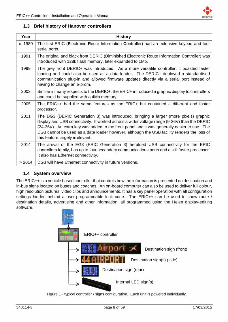
1.4 System overview
The ERIC++ is a vehicle based controller that controls how the information is presented on destination and
in-bus signs located on buses and coaches. An on-board computer can also be used to deliver full colour,
high resolution pictures, video clips and announcements. It has a key panel operation with all configuration
settings hidden behind a user-programmable lock code. The ERIC++ can be used to show route /
destination details, advertising and other information, all programmed using the Helen display-editing
software.
Figure 1 - typical controller / signs configuration. Each unit is powered individually.
Destination sign (front)
Destination sign(s) (side)
Destination sign (rear)
ERIC++ controller
Internal LED sign(s)
ERIC++ Controller – Installation and Operation Manual
540114-8 page 9 of 59 17/03/2015
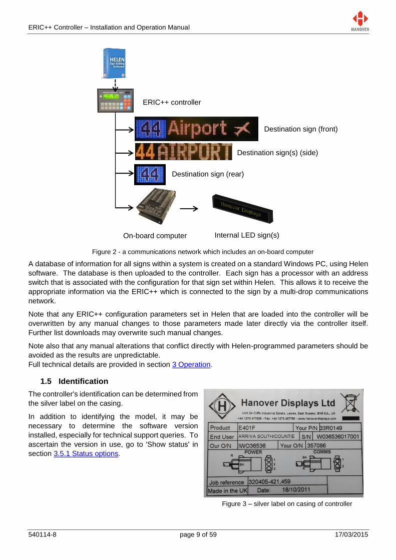
Figure 2 - a communications network which includes an on-board computer
A database of information for all signs within a system is created on a standard Windows PC, using Helen
software. The database is then uploaded to the controller. Each sign has a processor with an address
switch that is associated with the configuration for that sign set within Helen. This allows it to receive the
appropriate information via the ERIC++ which is connected to the sign by a multi-drop communications
network.
Note that any ERIC++ configuration parameters set in Helen that are loaded into the controller will be
overwritten by any manual changes to those parameters made later directly via the controller itself.
Further list downloads may overwrite such manual changes.
Note also that any manual alterations that conflict directly with Helen-programmed parameters should be
avoided as the results are unpredictable.
Full technical details are provided in section 3 Operation.
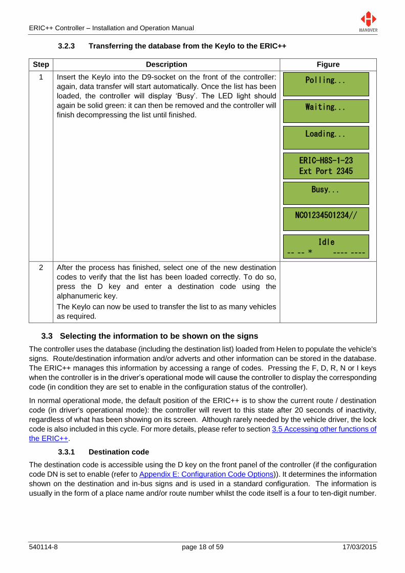
1.5 Identification
The controller's identification can be determined from
the silver label on the casing.
In addition to identifying the model, it may be
necessary to determine the software version
installed, especially for technical support queries. To
ascertain the version in use, go to 'Show status' in
section 3.5.1 Status options.
Figure 3 – silver label on casing of controller
Destination sign (front)
Destination sign(s) (side)
Destination sign (rear)
ERIC++ controller
On-board computer Internal LED sign(s)

ERIC++ Controller – Installation and Operation Manual
540114-8 page 10 of 59 17/03/2015
Features Meaning Description
Product - Identifies the specific model.
Your P/N Your Part Number Specific to each controller.
End User - Is generally the ultimate operator of the vehicle.
S/N Serial Number Specific to each controller.
Our O/N Our Order Number Number used for internal use by Hanover.
Your O/N Your Order
Number
Number used to identify the order for this controller.
Power connector Refer to section 2.2.1 Power.
Comms connector Refer to section 2.2.2 Communication.
Job reference - For the use of builder or end user.
Made in the UK - Shows the country of manufacture of the controller.
Date: Date when the finished controller is available for shipment
after all checks, tests and approvals are complete.
Exx-10R-yyyyyy European standard
E number
xx = country code.
10R = current version of standard.
yyyyyy = approval number applicable to this family of
products.
1.6 Controller overview
1.6.1 Front view
Figure 4 - front side of the controller
Front panel connector (9-way D type): for transferring destinations lists/updating firmware from a Keylo data loader or when using ERIC++ as a data loader via a serial cable
LCD display: provides visual information to the driver or user about the currently selected destination and operating status of the ERIC++
Alphanumeric keys: for entering route, destination, information and lock codes
X & Y: round trip (aller-retour)
F: Function 3.5 Accessing other functions of the ERIC++
R: Route D: Destination N: Advertising or next stop messages I: Information Up and down arrow keys:
for incrementing or decrementing destination, route or values
Ent: Enter For confirming selection or entry of data

ERIC++ Controller – Installation and Operation Manual
540114-8 page 11 of 59 17/03/2015
Lewes
-- -- * ---- ----
1.6.1.1 Example of LCD display
Figure 5 – Example of LCD display of the controller
1.6.2 Rear view
Figure 6 - rear side of the controller
1.7 Technical information
1.7.1 Specification
Specification Values / Description
Case dimensions W144mm x H96mm x D120mm
Mounting Dashboard / panel, using mounting housing bracket
Cut out required W138mm x H92mm x D150mm
Screen dimensions 59.5mm x 17.5mm
Screen display LCD with two lines of text maximum
Weight 0.9kg
Operating voltage 18-32Vdc
Normal operating power 0.5A @ 24Vdc
Operating temperature
range
-20°C to +60°C
Content of front sign or driver message for current destination
Destination code
Route code
Information code
Advert code * displayed if there is one or more sign errors
Power connector
Communication connector (RS485)
25-way D-type multicomms connector

ERIC++ Controller – Installation and Operation Manual
540114-8 page 12 of 59 17/03/2015
1.7.2 System supply voltages
All Hanover 24V devices are suitable for the full voltage supply range found on vehicles with a 24V battery.
For supply voltage details, please refer to the technical information for a specific product.

ERIC++ Controller – Installation and Operation Manual
540114-8 page 13 of 59 17/03/2015
Installation 2.
2.1 Standard positions for the controller are:
on the dash, to the right or left-hand side
in the sign pod
above or below the driver’s window.
Care must be taken to ensure enough space is provided at the rear of the controller unit for the power and
communication cables.
It is important to mount the controller in a suitable position for the driver for best access and visibility.
Position Advantages Disadvantages
Above or below the driver’s window or above the windscreen in the sign pod
This area usually has sufficient space to accommodate the controller and the cabling. It also allows easy access for maintenance.
Awkward for drivers to operate and difficult for them to view.
Left or right on the dash Good visibility and access. Wiring and servicing is normally straightforward.
Difficult to find sufficient depth of space on modern vehicles.
Below the pod above the driver’s head
Good visibility and access. Wiring and servicing is normally straightforward.
Possible water damage if window is opened.
2.2 System wiring
Cable assemblies can either be made by the user to their own requirements or ordered from Hanover.
2.2.1 Power
It is recommended that the ERIC++ is wired to a master switch or isolator switch.
The pins of the 3-pin power connector are:
Pin 1 = +24V
Pin 2 = 0V
Pin 3 = +24V optional output
Warning: Drivers should never attempt to operate the controller whilst driving.
The controller is not waterproof. Do not position the unit where it is likely to come into contact
with water / moisture – for example, under an opening window.
Water ingress is not covered by the product warranty.
Cables and connectors used must be appropriately rated for the particular vehicle
installation. Cable insulation should be selected in accordance with the application
requirements for heat, fire and smoke resistance.

ERIC++ Controller – Installation and Operation Manual
540114-8 page 14 of 59 17/03/2015
2.2.2 Communication
The pins of the 2-pin communication connector are:
Pin 1 = comms- (black)
Pin 2 = comms+ (red)
Note: The pins of the 2-pin sign communication connector are reversed in the case of a DERIC+ controller.
2.2.3 Multicomms
Wiring for bus reversing and battery guard is via the 25-way D-type drawing no. 0003/05/118. For more
information, refer to Appendix A: Cable Assembly Drawing.

ERIC++ Controller – Installation and Operation Manual
540114-8 page 15 of 59 17/03/2015
Operation 3.
3.1 Getting started
3.1.1 Boot screens on power-up
Whenever the ERIC++ is powered up or restarted, it carries out a series of initialising checks. Normally,
this sequence is rapid and can be ignored.
No. Description Figure
1 The green backlight becomes lit and the following start up screens
will be displayed.
Note: Some of the initial screen displays may appear very quickly.
2 If everything is correct, it will change to the driver's information
screen (NO DATA if no database has been transferred to the
controller or Idle if the controller already contains a database or last
destination code if programmed using configuration code RS (refer
to Appendix E: Configuration Code Options)) where the software
version is displayed. However, if an error occurs during software
initialisation, the screen may freeze while showing one of the codes.
If so, the user should restart the process. If this does not work, the
code should be noted and Hanover informed because it will help
establish the cause of the problem.
3.2 Loading a database into the ERIC++ from Helen
3.2.1 Base station and Keylo data loader
Figure 7 – base station and Keylo data loader
The most convenient device is the Keylo, a small, robust key fob device that fits easily in the pocket which
can be loaded from a PC via Helen software with an available USB port, taken to the vehicle and plugged
into the ERIC++ front panel connector where loading will start automatically.
3.2.2 Transferring the database to the Keylo dataloader using Helen
To load the database to the Keylo dataloader using Helen, please ensure the Keylo’s base station is
connected to the PC. For further details about the Keylo, please refer to “Keylo Operating Manual – ref.
0020/54/0039/F”.
abcd**...e
ERIC-H8S-1-23
Ext Port 2345
NCPO12345//
NO DATA
-- ----
Idle
-- -- * ---- ----
USB plug to PC
Base station
Keylo data loader

ERIC++ Controller – Installation and Operation Manual
540114-8 page 16 of 59 17/03/2015
Step Description Figure
1 In the main Helen window, click File Save Output
File as shown.
2 Verify that the options selected are correct and then
click OK.
For more details, refer to Helen display-editing
software operating manual (ref. 540125-10).
3 The ERIC.BIN file will be created as shown.
4 In the main Helen window, click File Send Output
File as shown.

ERIC++ Controller – Installation and Operation Manual
540114-8 page 17 of 59 17/03/2015
5 When the ‘SendWrap’ dialogue box appears, plug the
Keylo into the base station and data transfer will start
automatically.
Note: Please make sure ‘KEYLO1’ is set in Send Port.
6 When loading is finished, ‘Transfer complete’ will be
displayed briefly in the Status section of the Transfer
dialogue box. The LED on the Keylo will turn solid
green. The Keylo can now be removed.
Note: If the LED light on the Keylo is not solid green, try
loading the list again by removing the Keylo from the
base station and restarting the load process.
ERIC++ Controller – Installation and Operation Manual
540114-8 page 18 of 59 17/03/2015
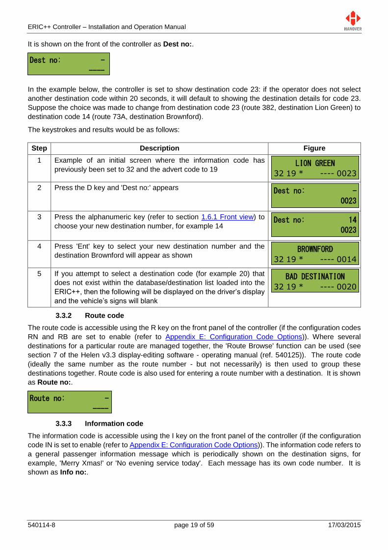
3.2.3 Transferring the database from the Keylo to the ERIC++
Step Description Figure
1 Insert the Keylo into the D9-socket on the front of the controller:
again, data transfer will start automatically. Once the list has been
loaded, the controller will display ‘Busy’. The LED light should
again be solid green: it can then be removed and the controller will
finish decompressing the list until finished.
2 After the process has finished, select one of the new destination
codes to verify that the list has been loaded correctly. To do so,
press the D key and enter a destination code using the
alphanumeric key.
The Keylo can now be used to transfer the list to as many vehicles
as required.
3.3 Selecting the information to be shown on the signs
The controller uses the database (including the destination list) loaded from Helen to populate the vehicle's
signs. Route/destination information and/or adverts and other information can be stored in the database.
The ERIC++ manages this information by accessing a range of codes. Pressing the F, D, R, N or I keys
when the controller is in the driver’s operational mode will cause the controller to display the corresponding
code (in condition they are set to enable in the configuration status of the controller).
In normal operational mode, the default position of the ERIC++ is to show the current route / destination
code (in driver's operational mode): the controller will revert to this state after 20 seconds of inactivity,
regardless of what has been showing on its screen. Although rarely needed by the vehicle driver, the lock
code is also included in this cycle. For more details, please refer to section 3.5 Accessing other functions of
the ERIC++.
3.3.1 Destination code
The destination code is accessible using the D key on the front panel of the controller (if the configuration
code DN is set to enable (refer to Appendix E: Configuration Code Options)). It determines the information
shown on the destination and in-bus signs and is used in a standard configuration. The information is
usually in the form of a place name and/or route number whilst the code itself is a four to ten-digit number.
Polling...
Waiting...
Loading...
ERIC-H8S-1-23
Ext Port 2345
Busy...
NC01234501234//
Idle
-- -- * ---- ----
ERIC++ Controller – Installation and Operation Manual
540114-8 page 19 of 59 17/03/2015
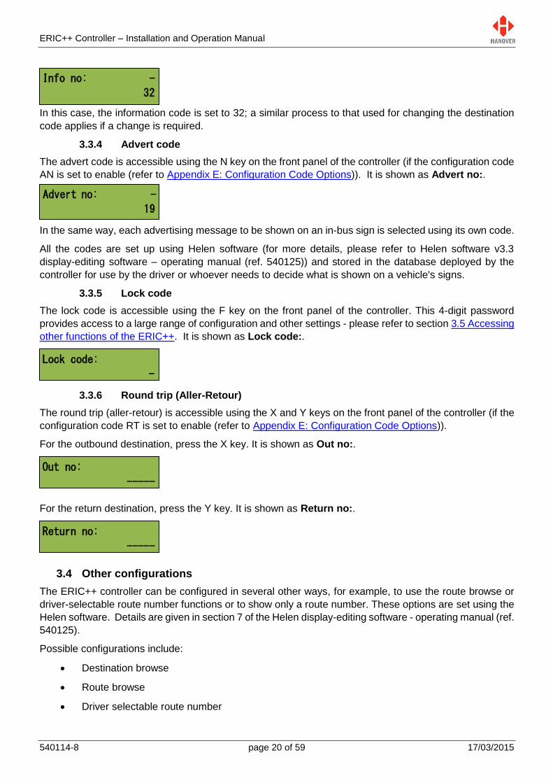
It is shown on the front of the controller as Dest no:.
In the example below, the controller is set to show destination code 23: if the operator does not select
another destination code within 20 seconds, it will default to showing the destination details for code 23.
Suppose the choice was made to change from destination code 23 (route 382, destination Lion Green) to
destination code 14 (route 73A, destination Brownford).
The keystrokes and results would be as follows:
Step Description Figure
1 Example of an initial screen where the information code has
previously been set to 32 and the advert code to 19
2 Press the D key and 'Dest no:' appears
3 Press the alphanumeric key (refer to section 1.6.1 Front view) to
choose your new destination number, for example 14
4 Press 'Ent' key to select your new destination number and the
destination Brownford will appear as shown
5 If you attempt to select a destination code (for example 20) that
does not exist within the database/destination list loaded into the
ERIC++, then the following will be displayed on the driver’s display
and the vehicle’s signs will blank
3.3.2 Route code
The route code is accessible using the R key on the front panel of the controller (if the configuration codes
RN and RB are set to enable (refer to Appendix E: Configuration Code Options)). Where several
destinations for a particular route are managed together, the 'Route Browse' function can be used (see
section 7 of the Helen v3.3 display-editing software - operating manual (ref. 540125)). The route code
(ideally the same number as the route number - but not necessarily) is then used to group these
destinations together. Route code is also used for entering a route number with a destination. It is shown
as Route no:.
3.3.3 Information code
The information code is accessible using the I key on the front panel of the controller (if the configuration
code IN is set to enable (refer to Appendix E: Configuration Code Options)). The information code refers to
a general passenger information message which is periodically shown on the destination signs, for
example, 'Merry Xmas!' or 'No evening service today'. Each message has its own code number. It is
shown as Info no:.
Dest no: -
----
LION GREEN
32 19 * ---- 0023
Dest no: -
0023
Dest no: 14
0023
BROWNFORD
32 19 * ---- 0014
BAD DESTINATION
32 19 * ---- 0020
Route no: -
----
ERIC++ Controller – Installation and Operation Manual
540114-8 page 20 of 59 17/03/2015
Advert no: -
19
In this case, the information code is set to 32; a similar process to that used for changing the destination
code applies if a change is required.
3.3.4 Advert code
The advert code is accessible using the N key on the front panel of the controller (if the configuration code
AN is set to enable (refer to Appendix E: Configuration Code Options)). It is shown as Advert no:.
In the same way, each advertising message to be shown on an in-bus sign is selected using its own code.
All the codes are set up using Helen software (for more details, please refer to Helen software v3.3
display-editing software – operating manual (ref. 540125)) and stored in the database deployed by the
controller for use by the driver or whoever needs to decide what is shown on a vehicle's signs.
3.3.5 Lock code
The lock code is accessible using the F key on the front panel of the controller. This 4-digit password
provides access to a large range of configuration and other settings - please refer to section 3.5 Accessing
other functions of the ERIC++. It is shown as Lock code:.
3.3.6 Round trip (Aller-Retour)
The round trip (aller-retour) is accessible using the X and Y keys on the front panel of the controller (if the
configuration code RT is set to enable (refer to Appendix E: Configuration Code Options)).
For the outbound destination, press the X key. It is shown as Out no:.
For the return destination, press the Y key. It is shown as Return no:.
3.4 Other configurations
The ERIC++ controller can be configured in several other ways, for example, to use the route browse or
driver-selectable route number functions or to show only a route number. These options are set using the
Helen software. Details are given in section 7 of the Helen display-editing software - operating manual (ref.
540125).
Possible configurations include:
Destination browse
Route browse
Driver selectable route number
Info no: -
32
Lock code:
-
Out no:
-----
Return no:
-----

ERIC++ Controller – Installation and Operation Manual
540114-8 page 21 of 59 17/03/2015
3.5 Accessing other functions of the ERIC++
A wide range of ERIC++ settings are accessible via the 'lock code' feature. Using the alphanumeric
keypad to key in the appropriate 4-digit lock code provides access to these settings. ERIC++ configuration
is best carried out by configuring the settings in Helen and downloading them into the controller. However,
manual changes to those parameters can then be made directly via the controller itself if required. Note
that any such changes will then be overwritten by a future download from Helen.
The functions are arranged hierarchically: in its normal operating mode, the controller shows level 1. The
table below shows how to navigate to the other functions.
1st level 2nd level 3rd level
Reach this list by pressing the F key
Reach this list by keying in the lock
code and using the Ent key.
Navigate through this list by using the
up / down arrow keys
Reach an option in this list by using
the Ent key
Navigate through the option list by
using the Ent key
To change this option, navigate
through the list by using the up /
down arrow keys and using the Ent
key
Lock code: Show status? 3.5.1 Status options
Test signs? 3.5.2 Running the signs test
Dump data? 3.5.3 Dump data screen sequence
Load data? 3.5.4 Load data
Operating mode? 3.5.5 Operating mode
Configure? 3.5.6 Configuration options
System? 3.5.7 System options
Ports? 3.5.8 Port options
Signs? 3.5.9 Sign options
Preview Dest? 3.5.10 Preview destination
HYVOX? 3.5.11 HYVOX
Note: To exit the function menu without selecting a menu item and to return to the normal driver’s display,
either:
Press Ent repeatedly until the end of the list is reached
Press Ent once, then press and hold Ent for 3 seconds: ERIC++ will reset, changes will then be saved
and will become effective
Press Ent once, then wait for more than 18 seconds approximately without pressing any key: any
changes made will not be saved
The 4-digit lock code is 9876 by default or if a factory reset is performed. However, if an
ERIC++ is loaded with a list from Helen, the lock code will be changed to 0101 as Helen has
by default a lock code of 0101.
If no lock code is entered for approximately 20 seconds, then the ERIC++ will revert to the last
driver’s display.

ERIC++ Controller – Installation and Operation Manual
540114-8 page 22 of 59 17/03/2015
3.5.1 Status options
This option provides access to information about the status and configuration of the controller and the
signs connected to it. The two ways to access this option are:
either holding down the Ent key for about 3 seconds. The HTC menu will be displayed first if
connected. Then, press the up arrow key to access the status option.
or by entering the lock code. 'Show status?' can be found from within the list and then selected
using the Ent key. Use the up and down arrow keys to navigate between each one.
Note: If accessing the status options by holding down the Ent button, the status options screen will be
displayed temporarily (only for a few seconds) and the ERIC++ will go back to its previous screen.
Whereas via the lock code, the status options screen will remain displayed until the user presses on the
Ent key to quit this option.
The following table shows all functions available in the status options:
No. Figure Description
1
ERICS: controller model
123: controller model software version number
– –: states of inputs I0 and I1 used with special feature such as
battery guard, bus reversing
Ok: indicates database loaded successfully (otherwise, error
code shown)
.4 .. 4 4 4 . : status of individual signs1
#: indicates bus stopping emergency feature activated
2
1087(g): database file size in bytes (file type)2
2.0Mb: flash memory capacity (needs to accommodate both
download file and operational database file)
00A5AE: database file checksum value
00-00:14: timer / clock showing length of time in use since last
reboot (DD-HH:MM = days-hours:minutes)
1 This code monitors the status fed back from up to 8 passenger information signs that can be connected to the
RS485 port. Each digit corresponds to one sign. The possible values and their meanings are:
. No sign connected
0 Sign connected and working correctly
1 Message content error
2 Checksum error
3 Halogen bulb failure (applies to flip dot signs but not to LED type signs)
4 No response from sign
5 Bad status reply
6 Communications error
2 Type of file loaded: (g)=compressed, (p)=plain, (e)=firmware, ()=old style database.
ERICS123 -- Ok
.4..444.#
1087(g) 2.0Mb
00A5AE 00-00:14

ERIC++ Controller – Installation and Operation Manual
540114-8 page 23 of 59 17/03/2015
3
PF: controller profile3
PF=X: where X indicates the value of the profile
369(g): profile size in bytes (Gzip file)
4
1:, 2:, 3:, 4:, 5:, 6:: sign numbers (+1) as set by Helen
software4
L: indicates route number set to left of sign (R=right)
160 x 19, 96 x 8, 144 x 19, 32 x 17: sign sizes (LED columns x
LED rows)
#X: X is the sign address as determined by its physical switch
setting5
3.5.2 Running the signs test
This test can be used to determine the source of a problem, i.e hardware, address settings or programming.
The controller sends a message via the communications network and activates the signs' internal test
mode. This will work irrespective of any settings or destination list configurations in the sign and in the
controller. To use this feature, the lock code must be entered, 'Test signs?' found from within the list and
then selected using the Ent key. 'Testing…' will flash until you press on the Ent key to stop the test.
For more details, please refer to the section 4.1.5 Sign test function.
3.5.3 Dump data screen sequence
This facility allows the database to be 'dumped' back on to a Keylo dataloader if required - generally to
enable the list to be copied to another controller.
Note: The list copied from the controller using 'Dump data' cannot be used in Helen.
The table below shows the procedure for dumping data:
Step Procedure Figure
1 Enter the lock code, find 'Dump data?' from within the list and
then select it using the Ent key.
2 Insert the Keylo dataloader into the front panel connector (9-way
D-type)
3 Dumping then starts automatically as shown
4 Dumping of data is now complete. This screen is shown for two
seconds – then reverts to operational status
3 This is a feature that makes it easy to manage a fleet of vehicles fitted with many different signs but all using the
same destination list. Full details are given in section 7.8.3 of the Helen v3.3 display-editing software - operating manual (ref. 540125). 4 Helen allocates numbers to each destination (and internal) sign configured by the software. By convention, these
start at 0. However, within the controller, 0 is reserved for the driver's sign on the front of the controller itself so all these numbers are incremented by 1. 5 There may be other signs with different switch settings included in the controller's configuration; in this example,
these signs are not currently connected to the controller and are thus 'inactive'.
PF=0: 369(g)
1 L 160x19 #0
2 L 96X8 #1
3 L 144x19 #2
4 L 144X19 #3
5 L 32x17 #4
6 L 32X17 #5
Dumping...
Dump completed
0090A6 575
ERIC++ Controller – Installation and Operation Manual
540114-8 page 24 of 59 17/03/2015
Mode:
Sign controller
Mode:
Data loader
3.5.4 Load data
The load data function allows you to load database/firmware via a CX105 – a data loading (serial) cable
from a PC.
It will support the loading of the controller directly from a laptop with a RS232 port (a CX105 cable must
ALSO be used).
This will also load old devices (black fronted DERICs) which do not support the Keylo loading system.
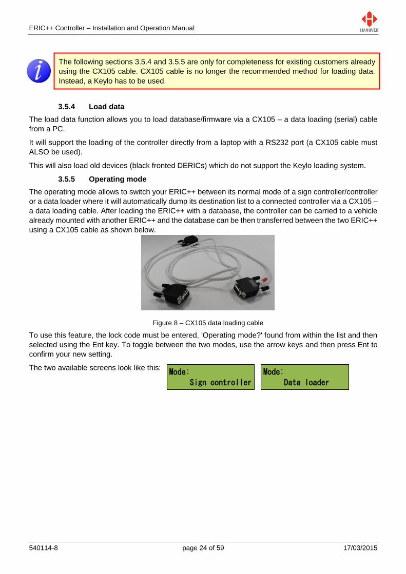
3.5.5 Operating mode
The operating mode allows to switch your ERIC++ between its normal mode of a sign controller/controller
or a data loader where it will automatically dump its destination list to a connected controller via a CX105 –
a data loading cable. After loading the ERIC++ with a database, the controller can be carried to a vehicle
already mounted with another ERIC++ and the database can be then transferred between the two ERIC++
using a CX105 cable as shown below.
Figure 8 – CX105 data loading cable
To use this feature, the lock code must be entered, 'Operating mode?' found from within the list and then
selected using the Ent key. To toggle between the two modes, use the arrow keys and then press Ent to
confirm your new setting.
The two available screens look like this:
The following sections 3.5.4 and 3.5.5 are only for completeness for existing customers already
using the CX105 cable. CX105 cable is no longer the recommended method for loading data.
Instead, a Keylo has to be used.

ERIC++ Controller – Installation and Operation Manual
540114-8 page 25 of 59 17/03/2015
Polling...
Waiting...
Listening...
Requesting...
Loading...
ERIC-H8S-1-22
Ext Port 2345
Busy...
NC01234501234//
Idle
-- -- * --- ----
Dumping...
Dump completed
Load aborted
Dump aborted
AL: 0
The data loader download sequence table is as follows:
Sign controller Data loader
The data loader now starts dumping the database file to the sign controller
If there was an error or the load was cancelled by pressing Ent, the following
screens will be displayed
3.5.6 Configuration options
When a database is downloaded from a PC, it incorporates parameters that determine how the ERIC++
operates and thereby drives the signs. Using the configuration function, these parameters can be viewed
and altered according to the user's requirements. To use this feature, the lock code must be entered,
'Configure?' found from within the list and then selected using the Ent key.
On the controller screen, there are currently 54 options (available in this edition). Use the Ent key to
navigate between each one. To change a setting, use the arrow keys and then press Ent to confirm.
An example screen looks like this:
For changing configuration settings, please refer to the ‘Note’ in 3.5 Accessing other functions of the
ERIC++.
For more details about the range of configuration code options, please refer to Appendix E: Configuration
Code Options.

ERIC++ Controller – Installation and Operation Manual
540114-8 page 26 of 59 17/03/2015
AF: BIN
P0: DIAG
S0: *
3.5.7 System options
The system function codes determine how the ERIC++ is set up as a controller. To use this feature, the
lock code must be entered, 'System?' found from within the list and then selected using the Ent key. On
the controller screen, there are currently 17 options (available in this edition). Use the Ent key to navigate
between each one. To change a setting, use the arrow keys and then press Ent to confirm.
An example screen looks like this:
The list of system options available in the ERIC++ controller is provided in Appendix B: System Options.
3.5.8 Port options
This setting allows a different comms protocol to be set for each port for use with the sign. To use this
feature, the lock code must be entered, 'Ports?' found from within the list and then selected using the Ent
key. There are currently 6 options (available in this edition). Use the Ent key to navigate between each one.
To change a setting, use the arrow keys and then press Ent to confirm.
An example screen looks like this:
The list of protocols available in the ERIC++ controller is provided in Appendix C: Protocols – Port Options.
Note: Controllers are not necessarily supplied with every possible protocol enabled.
For more details about any protocol, please contact Hanover (please refer to section 4.3 Hanover
Technical Support).
3.5.9 Sign options
This is an optional manual override to enable the contents of a sign to be changed to display a different
programmed sign in Helen. To use this feature, the lock code must be entered, 'Signs?' found from within
the list and then selected using the Ent key. There are currently 17 options (available in this edition). Use
the Ent key to navigate between each one. To change a setting, use the arrow keys and then press Ent to
confirm.
An example screen looks like this:
The list of sign options available in the ERIC++ controller is provided in Appendix D: Sign Options.
3.5.10 Preview destination
This option allows the user to directly visualize the list of destinations available in his database via the
automatic scroll of the list of destinations or by simply using the arrow keys to navigate through the list.
To use this feature, the lock code must be entered, 'Preview Dest?' found from within the list and then
selected using the Ent key.
Do not use the same protocol on more than one port: the results are unpredictable.
Be careful when using sign options as the physical sign addresses may be different from the
sign addresses set up in Helen.
ERIC++ Controller – Installation and Operation Manual
540114-8 page 27 of 59 17/03/2015
HYVOX?
HTC Terminal Menu
Sim Enabled (No)
Sim Enabled
Yes/No No
Sim Enabled
Yes/No Yes
HTC Terminal Menu
Sim Enabled (Yes)
3.5.11 HYVOX
This menu item will only become enabled if your ERIC++ has a Hancis or HTC unit connected to the
physical sign system in your vehicle and if HANCIS/HTC is selected as a sign. Setting the sign no. to the
‘HANCIS/HTC’ value (refer to 3.5.9 Sign options) will enable the ERIC++ to remotely control certain
features (for example, the audio, IP address, etc.) of the Hancis/HTC unit.
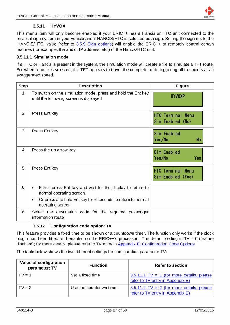
3.5.11.1 Simulation mode
If a HTC or Hancis is present in the system, the simulation mode will create a file to simulate a TFT route.
So, when a route is selected, the TFT appears to travel the complete route triggering all the points at an
exaggerated speed.
Step Description Figure
1 To switch on the simulation mode, press and hold the Ent key
until the following screen is displayed
2 Press Ent key
3 Press Ent key
4 Press the up arrow key
5 Press Ent key
6 Either press Ent key and wait for the display to return to
normal operating screen.
Or press and hold Ent key for 6 seconds to return to normal
operating screen
6 Select the destination code for the required passenger
information route
3.5.12 Configuration code option: TV
This feature provides a fixed time to be shown or a countdown timer. The function only works if the clock
plugin has been fitted and enabled on the ERIC++'s processor. The default setting is TV = 0 (feature
disabled); for more details, please refer to TV entry in Appendix E: Configuration Code Options.
The table below shows the two different settings for configuration parameter TV:
Value of configuration
parameter: TV Function Refer to section
TV = 1 Set a fixed time 3.5.11.1 TV = 1 (for more details, please
refer to TV entry in Appendix E)
TV = 2 Use the countdown timer 3.5.11.2 TV = 2 (for more details, please
refer to TV entry in Appendix E)

ERIC++ Controller – Installation and Operation Manual
540114-8 page 28 of 59 17/03/2015
Depart Time?
Time: -
--:--
Depart Time?
Minutes: -
--
3.5.12.1 TV = 1 (for more details, please refer to TV entry in Appendix E)
How to set a fixed time:
Step Description Figure
1 Further to setting TV=1 in the ERIC++’s configuration, press the
F key on the front panel of the controller.
2 The screen showing “Depart Time?” is displayed.
3 Press Ent key. The screen showing the time in hh:mm (in
24-hour format) is displayed.
4 Use the alphanumeric keys to set the time value.
Then, press Ent key to confirm and exit the function.
Note: The time entered here will be substituted for any ‘~’ (tilde) character within the Helen destination or
driver display database. It is sometimes used by drivers ‘on the fly’ for entering departure times. The
destination message might thus be 'Bus departs at ~'.
3.5.12.2 TV = 2 (for more details, please refer to TV entry in Appendix E)
How to use the countdown timer:
Step Description Figure
1 Further to setting TV=2 in the ERIC++’s configuration, press
the F key on the front panel of the controller.
2 The screen showing “Depart Time?” is displayed.
3 Press Ent key. The screen showing the countdown in minutes
(can be set between 1 and 99) is displayed.
4 Use the alphanumeric keys to set the minutes value.
Then, press Ent key to confirm and exit the function.
If TV has been configured to 1 or 2, the up arrow key needs to be pressed in order to regain
access to the lock code under the F key.
The message generated in Helen for the sign must be in text mode for this function to work.
ERIC++ Controller – Installation and Operation Manual
540114-8 page 29 of 59 17/03/2015
Note: The value entered here will be substituted for any ‘~’ (tilde) character within the Helen destination
lists: this causes the destination / route code containing the tilde character ('~') to start counting down to
zero on the sign when the code is selected. When zero is reached, the clock stops and '0' remains on the
sign until another destination / route code is selected. The destination message might thus be 'Bus
departs in ~ minutes'.
3.5.13 External input options
Emergency message, battery guard, bus stopping and bus reversing features are all triggered by ERIC++
sensing the voltage level present on pins of the rear 25-way D-type multicomms connector. A suitable
cable assembly such as CX108 and a connection to a switch and/or vehicle ignition are required.
The pins of the multicomms connector operate at +24V logic levels which are either voltage high (+24V) for
1 or voltage low (0V) for 0. The pins are fed by a signal from the ignition switch, bus stopping button,
emergency button or some other switch device on the bus as appropriate.
For more details about the CX108 - ERIC++ bus reversing and battery guard connection cable, please
refer to Appendix A: Cable Assembly Drawing.
ERIC++ has two separate inputs I0 and I1 that can be used simultaneously allowing two functions to be
implemented at the same time, for example, battery guard and bus reversing.
The available options and their meanings are shown below. For more details, please refer to the I0 and I1
entries in the configuration code options table in Appendix E: Configuration Code Options.
3.5.13.1 Emergency message
Setting I0 and I1 to the values 1, 2, 3 and 4 are all for emergency messages. When the input is activated,
the message (for example, "Emergency - Call Police") associated with a particular destination code is
shown on the signs. By default, this is 9999, or (0000 9999 for route browse). This code can be changed
by adding the parameter EC = nnnn to the database configuration, where nnnn is the preferred emergency
destination code. This is done in Helen via the Extensions box on the Advanced tab of a particular profile
in 'Controller Config'.
By not setting a driver’s message for this emergency destination, the driver’s controller screen will not
change from the previous destination when the input is activated, although the destination signs will. The
user may decide that this is preferable if, for example, the driver is being threatened or is under attack.
Note: Value 3 is being mainly used for bus reversing. However, the bus reversing function can now be set
using the values BR or BRI (refer to 3.5.13.7 Displaying ‘Bus reversing’).

ERIC++ Controller – Installation and Operation Manual
540114-8 page 30 of 59 17/03/2015
SIGNS BLANKED
XXXXXXXXXXXXXXXX
I0 or I1
Value Meaning Description
1 latched When the input is activated (volts on input), the emergency destination will
remain, even if the input is deactivated. The destination must be manually reset.
2 latched
(inverted) As above but input sensing is inverted (volts = inactive; no volts = active).
3 unlatched Once the input is activated (volts on input), the emergency destination will
remain for only as long as the input remains active.
4 unlatched
(inverted) As above but input sensing is inverted (volts = inactive; no volts = active).
3.5.13.2 Blanking the sign (battery guard)
Setting I0 and I1 to the values 5 and 6 are for blanking the sign (designed to save battery life). When the
input is activated, the controller works as normal. When deactivated, the signs will be blanked after a time
delay set by configuration parameter BT = n where n is in minutes (default n = 0). For more details about
BT, please refer to entry BT in Appendix E: Configuration Code Options.
Another parameter BL, meaning brightness level (0 (by default) means maximum brightness, 1 means
minimum brightness and 2-99 means actual maximum brightness) sets the brightness of exterior LED
displays during the BT-defined time delay period. For more details about BL, please refer to entry BL in
Appendix E: Configuration Code Options.
I0 or I1
Value Meaning Description
5 blanking When inactive (no volts), signs will be blanked after period BT.
6 blanking
(inverted) As above but input sensing is inverted (volts = inactive; no volts = active).
When the Blank Time (BT) is up, the screen looks like this:
Blanking the sign in this way should not be confused with the 'Blank code' facility, which is a destination
code set within Helen that defines what is shown on an otherwise blank sign - for example, if a non-existent
code is selected or the controller is set to an idle state. For more details, please refer to the Helen v3.3
display-editing software - operating manual (ref. 540125), section 7.3.5. However, the destination defined
by that code will also be shown during the BT-defined delay described above.
3.5.13.3 Displaying ‘Bus stopping’
Setting I0 and I1 to the values 7 and 8 are to set up 'Bus stopping' on a sign. On activation, in-bus signs will
automatically show 'Bus stopping', overriding the previous message.
Alternatively, the 'bus stopping' message can be programmed for in-bus signs under a destination code
containing the two characters 'BS' - for example: BS01 (or BS00000001) or 0000 BS01 for route browse.
In both cases, the parameter LN = n must be used to indicate the number allocated to the in-bus sign,
where n is any of the values provided in sign options. The LN setting is made within 'Sign options' (for more
details, please refer to section 3.5.9 Sign options).

ERIC++ Controller – Installation and Operation Manual
540114-8 page 31 of 59 17/03/2015
I0 or I1
Value Meaning Description
7 bus
stopping
Whilst the input is active (volts on input), the in-bus sign will show the
programmed message.
8
bus
stopping
(inverted)
As above but input sensing is inverted (volts = inactive; no volts = active).
3.5.13.4 Information message
Values IN and INI are for information messages. An information message is selected on activation of the
external input, having been set up within the Helen database in a similar way to a destination message.
The message is enabled by adding the parameter IC = nn, where nn = 01 - 99. This is done in Helen via
the Extensions box on the Advanced tab of a particular profile in 'Controller Config.' (nn corresponds with
the message number in the Helen database).
The parameter IP is used in conjunction with this. Please refer to the IP entry in the table in Appendix E:
Configuration Code Options.
3.5.13.5 Destination VOX (Hanvox) audio message
Values DV and DVI are Destination VOX (Hanvox). On activation, if Hanvox is configured and present
within the system, an mp3 audio message associated with the destination / route code currently in use by
the controller will be played twice. This works by Hanvox receiving a message from the controller in the
form 'p /e Dnnnn' where nnnn is the current destination code. If the system is configured to use Route
Browse, the route code must be a maximum of three characters: this is because Dnnnn can be a maximum
of eight characters.
This feature is enabled in Helen via the Extensions box on the Advanced tab of a particular profile in
Controller Config: it is sufficient simply to add 'DV' or 'DVI' as appropriate in the box.
I0 or I1
Value Meaning Description
DV Destination HanVox
Message is played twice when input active (volts on input)
DVI Destination HanVox (inverted)
As above, but input sensing is inverted (volts = inactive; no volts = active).
Note: When using the Extensions box in Helen software, several different configuration codes can be
added if required; they should be separated by a comma.
3.5.13.6 E, I and EI values
Values E, I and EI are for an external, internal or both an internal and external input configuration
parameter.
I0 or I1
Value Meaning Description
IN information Whilst the input is active (volts on input) the information message will be selected.
INI information (inverted)
As above but input sensing is inverted (volts = inactive; no volts = active).

ERIC++ Controller – Installation and Operation Manual
540114-8 page 32 of 59 17/03/2015
This feature is enabled in Helen via the Extensions box on the Advanced tab of a particular profile in
Controller Config: it is sufficient simply to add 'E' or 'I' or 'EI' as appropriate in the box.
I0 or I1
Value Meaning Description
E External When door is opened (active high), “p /e Ennnn” message is sent causing External announcement of file Ennnn.mp3 (where nnnn is the current destination code)
I Internal When door is closed (active low), “p Innnn” message is sent causing Internal announcement of file Innnn.mp3 (where nnnn is the current destination code)
EI External and Internal
Both above actions are acted upon
3.5.13.7 Displaying ‘Bus reversing’
Values BR and BRI are for 'Bus reversing'. The bus reversing message is programmed under a
destination code whose most significant two characters are 'BR' - for example: BR01 (or BR00000001) or
0000 BR01 for route browse.
The destination code should only contain a message for the signs which are to show it, i.e if the front sign
is not to change, no message content should be entered for the front sign for this destination.
I0 or I1
Value Meaning Description
BR Bus Reversing
Whilst the input is active (volts on input), the signs will show the programmed message.
BRI Bus Reversing (inverted)
As above, but input sensing is inverted (no volts = active).
Note: The bus reversing message can also be set using a destination code of 9999 (please refer to
3.5.13.1 Emergency message).
3.5.14 Reset options
#
There are 3 types of reset options available for ERIC++: factory lock code reset, configuration reset and
factory reset as described below.
Factory lock code reset: for resetting the lock code to the default factory value (9876).
Configuration reset: for resetting all parameters within the configuration menu (refer to 3.5.6
Configuration options) to their default factory values.
Factory reset: for resetting all parameters behind the lock code to their default factory values and
erasing the database.
Be careful when using these functions. Incorrect or improper use will erase the currently stored database and / or may reset all configuration and system parameters rendering your ERIC++ unusable within the vehicle.
ERIC++ Controller – Installation and Operation Manual
540114-8 page 33 of 59 17/03/2015
3.5.14.1 Factory lock code reset
Step Procedure
1 Switch off power to the ERIC++
2 Hold both the up and down arrow keys
3 Switch on power to the ERIC++ while maintaining the up and down arrow keys pressed for at
least 3 seconds
4 The lock code will now be reset to the default factory value (9876) although there is no display on
the screen to confirm this
3.5.14.2 Configuration reset
Step Procedure
1 Switch off power to the ERIC++
2 Hold both the I and Ent keys
3 Switch on power to the ERIC++ while maintaining the I and Ent keys pressed for at least 3
seconds
4 All parameters within the configuration menu will be reset to their default factory values although
there is no display on the screen to confirm this
3.5.14.3 Factory reset
Step Procedure
1 Switch off power to the ERIC++
2 Hold both the F and Ent keys
3 Switch on power to the ERIC++ while maintaining the F and Ent keys pressed for at least 3
seconds
4 All parameters behind the lock code will be reset to their default factory values and this will erase
the database although there is no display on the screen to confirm this.
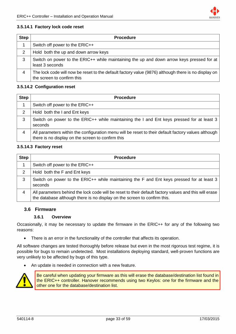
3.6 Firmware
3.6.1 Overview
Occasionally, it may be necessary to update the firmware in the ERIC++ for any of the following two
reasons:
There is an error in the functionality of the controller that affects its operation.
All software changes are tested thoroughly before release but even in the most rigorous test regime, it is
possible for bugs to remain undetected. Most installations deploying standard, well-proven functions are
very unlikely to be affected by bugs of this type.
An update is needed in connection with a new feature.
Be careful when updating your firmware as this will erase the database/destination list found in the ERIC++ controller. Hanover recommends using two Keylos: one for the firmware and the other one for the database/destination list.
ERIC++ Controller – Installation and Operation Manual
540114-8 page 34 of 59 17/03/2015
3.6.2 ERIC++’s firmware version
To know which firmware version your ERIC++ is equipped with, there are two ways of checking it:
1st way: Press the Ent key for a few seconds. The firmware version will be displayed as ERICS1XX.
In this case, the firmware version will remain on the screen for a few seconds before it reverts to the
last standard driver’s screen before Ent key was pressed.
2nd way: Press the F key, the lock code must be entered, 'Show status?' found from within the list
and then selected using the Ent key. The firmware version will be displayed as ERICS1XX. In this
case, the firmware version will remain on the screen until you exit the function by pressing on the
Ent key.
For any enquiry about the latest released firmware version, please contact Hanover (please refer to
section 4.3 Hanover Technical Support).
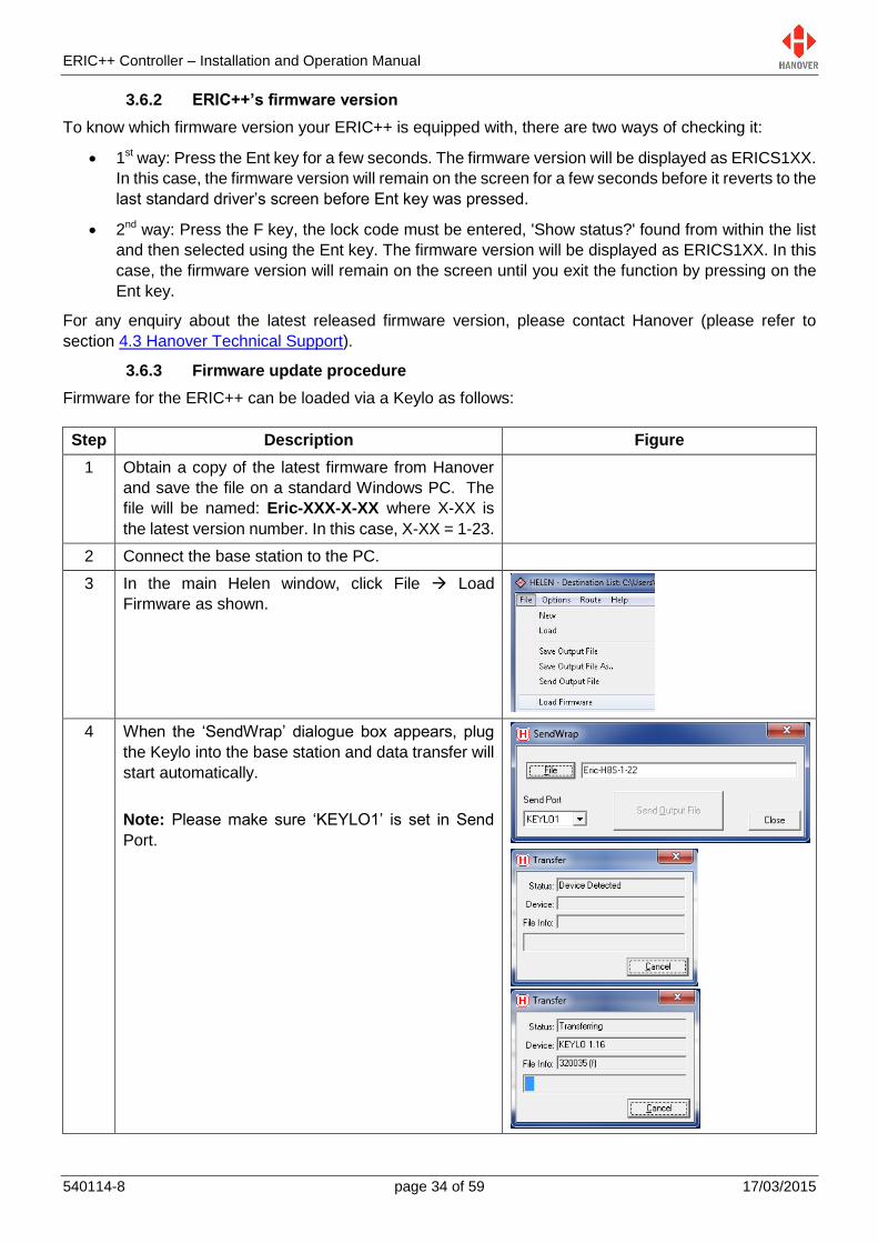
3.6.3 Firmware update procedure
Firmware for the ERIC++ can be loaded via a Keylo as follows:
Step Description Figure
1 Obtain a copy of the latest firmware from Hanover
and save the file on a standard Windows PC. The
file will be named: Eric-XXX-X-XX where X-XX is
the latest version number. In this case, X-XX = 1-23.
2 Connect the base station to the PC.
3 In the main Helen window, click File Load
Firmware as shown.
4 When the ‘SendWrap’ dialogue box appears, plug
the Keylo into the base station and data transfer will
start automatically.
Note: Please make sure ‘KEYLO1’ is set in Send
Port.

ERIC++ Controller – Installation and Operation Manual
540114-8 page 35 of 59 17/03/2015
Polling
Waiting
Loading
ERIC-H8S-1-22
Ext Port 2345
Please wait
///
ERIC-H8S-1-22
Ext Port 2345
Erasing...
Ext Port 2345
NCP012345//
NO DATA
-- ----
5 When loading is finished, ‘Transfer complete’ will be
displayed briefly in the Status section of the Transfer
dialogue box. The LED on the Keylo will turn solid
green. The Keylo can then be removed.
Note: If the LED light on the Keylo is not solid green,
try loading the list again by removing the Keylo from
the base station and restarting the load process.
6 Power up the ERIC++ controller and plug the Keylo
into its front panel connector (9-way D-type).
7 The ERIC++ will start installing the firmware. When
the installation is finished, the LED of the Keylo will
turn solid green. The Keylo can then be removed.
8 The following screen will be displayed.
9 As an update of the firmware erases the database
(destination list) of the controller,
the database has to be transferred to the Keylo
using Helen software. Please refer to 3.2.2
Transferring the database to the Keylo
dataloader using Helen
and then transferred from the Keylo to the
ERIC++. Please refer to 3.2.3 Transferring the
database from the Keylo to the ERIC++

ERIC++ Controller – Installation and Operation Manual
540114-8 page 36 of 59 17/03/2015
Troubleshooting 4.
4.1 Overview
This section lists the more common queries that occur with the ERIC++ controller. The controller is not
intended for disassembly by the user. Hanover should be consulted (please refer to section 4.3 Hanover
Technical Support) if a solution cannot be found by means of altering settings manually or via the Helen
software as described below.
Section Issue
4.1.1 No display or backlight on controller
4.1.2 No communication or required information not displayed on signs
4.1.3 List will not load into ERIC++ controller
4.1.4 ERIC++ loads list correctly but shows 'Bad Destination or Bad Route'
4.1.5 Sign test function
4.1.6 Information code on controller screen shows '??'
4.1.7 Advert code on controller screen shows '??'
4.1.8 On-screen response erratic when using keypad
4.1.9 Faults not listed here
4.1.1 No display or backlight on controller
No. Description Refer to section
1 Check that the 3-way power connector is wired correctly by
making sure the pins are pushed in securely into the connector
and that the required voltage is present
2.2.1 Power
4.1.2 No communication or required information not displayed on signs
No. Description Refer to section
1 Check that the comms are wired correctly by making sure the pins
are pushed in securely into the 2-way comms connector
1.6.2 Rear view
2 Check all other cables and connections
3 Run the signs test to check that power and communications are
reaching each sign.
When ERIC++ shows 'Testing…' as shown, a test pattern should
be visible on the signs:
If visible, the destination list loaded is possibly not compatible
with the sign system on the vehicle. Check that the Helen
database file has been configured correctly
If not visible, then there is probably a hardware /
communications problem
3.5.2 Running the signs test
4.1.5 Sign test function
4 A sign status check can also be run 3.5.1 Status options

ERIC++ Controller – Installation and Operation Manual
540114-8 page 37 of 59 17/03/2015
Testing...
4.1.3 List will not load into ERIC++ controller
No. Description Refer to
1 Check there is a valid destination list in the Keylo and that it has
been correctly configured
Keylo Operating Manual
(ref. 0020/54/0039/F)
2 If problem still persists, check if the Keylo is faulty
4.1.4 ERIC++ loads list correctly but shows ‘Bad Destination or Bad Route’
No. Description Refer to
1 Ensure a valid destination or route code is being entered
2 The database may have been saved and loaded as a standard
4-digit code rather than a 10-digit route browse (or vice versa).
Check in Helen that the correct option has been selected
Figure of step 1 in 3.2.2
Transferring the database to
the Keylo dataloader using
Helen
3 Resave the database to the Keylo if necessary and then upload it
to the ERIC++ again
4.1.5 Sign test function
The sign test function tests all the signs connected to the ERIC++ controller. This function is accessed via
the menu behind the lock code (please refer to section 3.5 Accessing other functions of the ERIC++), 'Test
signs?' found from within the list and then selected using the Ent key.
The screen looks like this:
The controller will then flash ‘Testing’ as shown above and send a message to all the connected signs for
them to show a repeating test pattern. This test pattern verifies that the signs and the controller are
communicating with each other and that for LED signs, the individual LEDs are working correctly.
LED signs will show a scrolling message followed by an alternating test pattern (the content of the scrolling
message is described below) whilst flip dot signs will show just the test pattern. There will be some
variation in what is scrolled across the sign, depending on firmware, display size etc., but the key areas will
be the same.
Failure of this test sequence to appear indicates that power and / or communications are not present and /
or cables may have been incorrectly connected.
ERIC++ Controller – Installation and Operation Manual
540114-8 page 38 of 59 17/03/2015
Info no: -
--
Advert no: -
--
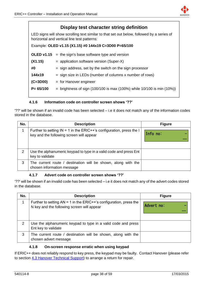
4.1.6 Information code on controller screen shows ‘??’
'??' will be shown if an invalid code has been selected – i.e it does not match any of the information codes stored in the database.
No. Description Figure
1 Further to setting IN = 1 in the ERIC++’s configuration, press the I
key and the following screen will appear
2 Use the alphanumeric keypad to type in a valid code and press Ent
key to validate
3 The current route / destination will be shown, along with the
chosen information message
4.1.7 Advert code on controller screen shows ‘??’
'??' will be shown if an invalid code has been selected – i.e it does not match any of the advert codes stored
in the database.
No. Description Figure
1 Further to setting AN = 1 in the ERIC++’s configuration, press the
N key and the following screen will appear
2 Use the alphanumeric keypad to type in a valid code and press
Ent key to validate
3 The current route / destination will be shown, along with the
chosen advert message
4.1.8 On-screen response erratic when using keypad
If ERIC++ does not reliably respond to key press, the keypad may be faulty. Contact Hanover (please refer
to section 4.3 Hanover Technical Support) to arrange a return for repair.
Display test character string definition
LED signs will show scrolling text similar to that set out below, followed by a series of
horizontal and vertical line test patterns:
Example: OLED v1.15 (X1.15) #0 144x19 C=3D00 P=65/100
OLED v1.15 = the sign's base software type and version
(X1.15) = application software version (Super-X)
#0 = sign address, set by the switch on the sign processor
144x19 = sign size in LEDs (number of columns x number of rows)
(C=3D00) = for Hanover engineer
P= 65/100 = brightness of sign (100/100 is max (100%) while 10/100 is min (10%))
ERIC++ Controller – Installation and Operation Manual
540114-8 page 39 of 59 17/03/2015
4.1.9 Faults not listed here
The most commonly occurring faults have been described above. However, other fault conditions can
occur occasionally. These often arise during data loading or because of communication set-up problems.
Such faults can be identified by using the 'Show Status' function. Please refer to section 3.5.1 Status
options.
4.2 If troubleshooting does not solve the problem
If the troubleshooting guide fails to solve the problem, Hanover should be contacted for advice. However,
please gather the following list of information before contacting Hanover Technical Support:
No. Information Where it is found Refer to section
1 Software version of ERIC++ 3.6.2 ERIC++’s firmware
version
2 Product code of ERIC++ On the silver label on the
casing (if accessible)
1.5 Identification
3 Product codes of signs connected
to the ERIC++
On the rear panels of signs
4 Nature of problem, including what
is or is not being displayed by the
ERIC++ and the signs connected
to it
5 The eric.bin and corresponding
Helen data files
4.3 Hanover Technical Support
4.3.1 United Kingdom
Please do not hesitate to contact Hanover Technical Support located in Lewes, UK for any problem
encountered or for any advice needed for using the ERIC++ controller:
Contact
Phone +44 (0)1273 477528 Ext.615 or Option 2
Email [email protected]
4.3.2 United States of America
Please do not hesitate to contact Hanover Technical Support located in USA for any problem encountered
or for any advice needed for using the ERIC++ controller:
Contact
Phone +1 (773) 334 9934
Email [email protected]
ERIC++ Controller – Installation and Operation Manual
540114-8 page 40 of 59 17/03/2015
Queries, FAQs and other information 5.
5.1 Overview
The previous section provides in-depth information on diagnosing problems that can occur with the
ERIC++. This 'how to' section provides answers to typical questions and queries associated with the unit
and includes cross-references and links where appropriate to the relevant sections of the manual.
If the answer is not found here, users can contact Hanover Technical Support – please refer to section 4.3
Hanover Technical Support.
5.2 Queries
How to: Refer to section
Determine the sizes and addresses of the signs 3.5.1 Status options
Mimic the content of a specific display on the
controller screen
DD entry in Appendix E: Configuration Code
Options
Reset the ERIC++ 3.5.15 Reset options
Change the language setting in the ERIC++ LG entry in Appendix B: System Options
Add a 'bus reversing' message to the signs 3.5.13.7 Displaying ‘Bus reversing’
Add an 'emergency' message to the signs 3.5.13.1 Emergency message
Use the 'battery guard' feature 3.5.13.2 Blanking the sign (battery guard)
5.3 Frequently asked questions
Questions Answers
Do I need a special loading device? Yes, a base station and a Keylo data loader are
needed for downloading the database to the ERIC++.
Refer to 3.2.1 Base station and Keylo data loader.
A CX105 – a data loading (serial) cable is also
needed if ERIC++ is used as a data loader. Refer to
3.5.5 Operating mode.
How do I install Keylo drivers? For Helen version 3.3 or below:
Ensure Helen has been correctly installed
Check that the base station is not connected
to the PC
Go to Start / All Programs / Hanover Displays /
Install Keylo Drivers*.
Follow the instructions given by the driver
installation wizard
On connecting the base station, the drivers
will be installed
How do I load the ERIC++? A database of destination information (plus adverts
and other messages if required) is prepared on a
standard Windows PC using Helen display-editing
ERIC++ Controller – Installation and Operation Manual
540114-8 page 41 of 59 17/03/2015
software. This is transferred to a Keylo and then
loaded directly into the ERIC++. Please refer to
sections 3.2.2 Transferring the database to the Keylo
dataloader using Helen and 3.2.3 Transferring the
database from the Keylo to the ERIC++.
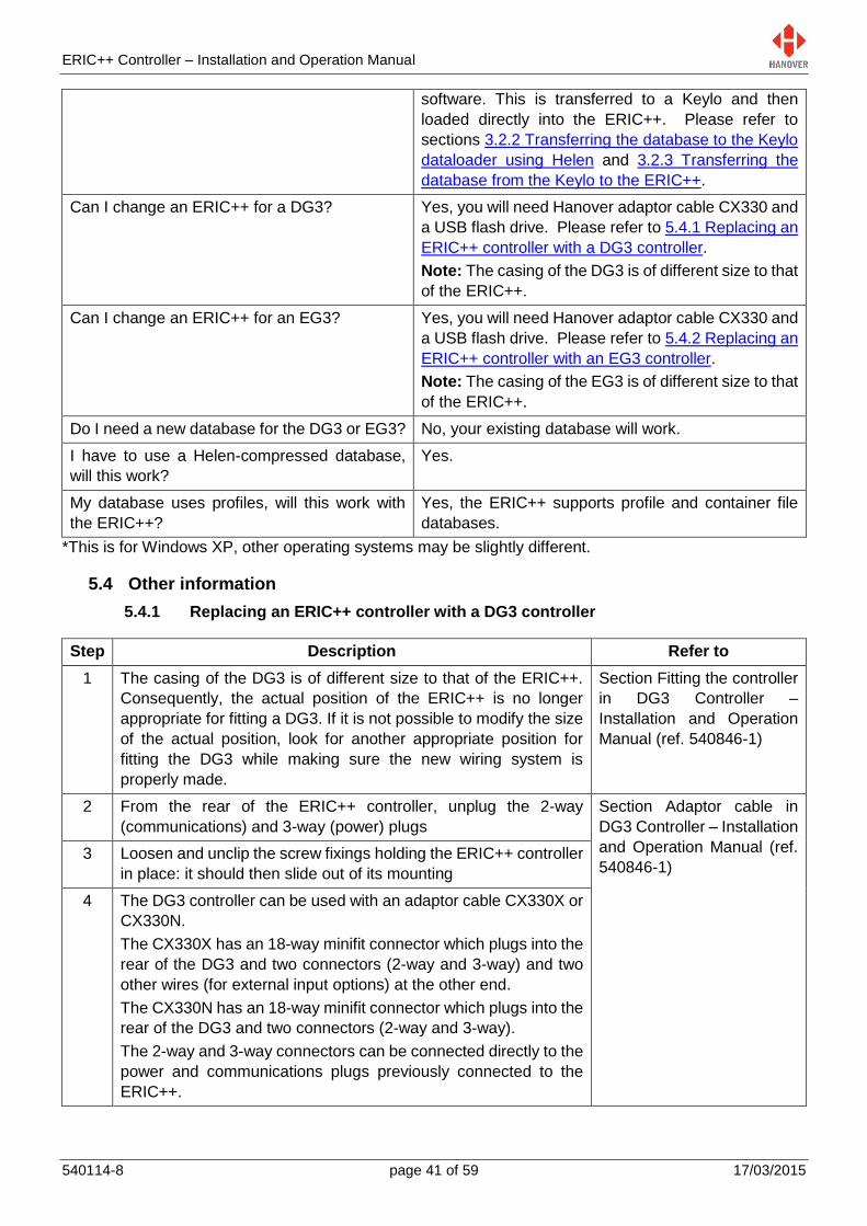
Can I change an ERIC++ for a DG3? Yes, you will need Hanover adaptor cable CX330 and
a USB flash drive. Please refer to 5.4.1 Replacing an
ERIC++ controller with a DG3 controller.
Note: The casing of the DG3 is of different size to that
of the ERIC++.
Can I change an ERIC++ for an EG3? Yes, you will need Hanover adaptor cable CX330 and
a USB flash drive. Please refer to 5.4.2 Replacing an
ERIC++ controller with an EG3 controller.
Note: The casing of the EG3 is of different size to that
of the ERIC++.
Do I need a new database for the DG3 or EG3? No, your existing database will work.
I have to use a Helen-compressed database,
will this work?
Yes.
My database uses profiles, will this work with
the ERIC++?
Yes, the ERIC++ supports profile and container file
databases.
*This is for Windows XP, other operating systems may be slightly different.
5.4 Other information
5.4.1 Replacing an ERIC++ controller with a DG3 controller
Step Description Refer to
1 The casing of the DG3 is of different size to that of the ERIC++.
Consequently, the actual position of the ERIC++ is no longer
appropriate for fitting a DG3. If it is not possible to modify the size
of the actual position, look for another appropriate position for
fitting the DG3 while making sure the new wiring system is
properly made.
Section Fitting the controller
in DG3 Controller –
Installation and Operation
Manual (ref. 540846-1)
2 From the rear of the ERIC++ controller, unplug the 2-way
(communications) and 3-way (power) plugs
Section Adaptor cable in
DG3 Controller – Installation
and Operation Manual (ref.
540846-1) 3 Loosen and unclip the screw fixings holding the ERIC++ controller
in place: it should then slide out of its mounting
4 The DG3 controller can be used with an adaptor cable CX330X or
CX330N.
The CX330X has an 18-way minifit connector which plugs into the
rear of the DG3 and two connectors (2-way and 3-way) and two
other wires (for external input options) at the other end.
The CX330N has an 18-way minifit connector which plugs into the
rear of the DG3 and two connectors (2-way and 3-way).
The 2-way and 3-way connectors can be connected directly to the
power and communications plugs previously connected to the
ERIC++.
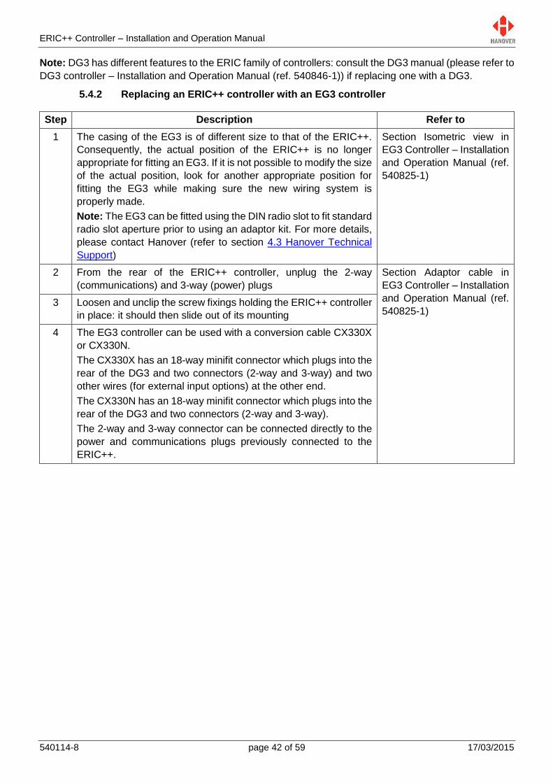
ERIC++ Controller – Installation and Operation Manual
540114-8 page 42 of 59 17/03/2015
Note: DG3 has different features to the ERIC family of controllers: consult the DG3 manual (please refer to
DG3 controller – Installation and Operation Manual (ref. 540846-1)) if replacing one with a DG3.
5.4.2 Replacing an ERIC++ controller with an EG3 controller
Step Description Refer to
1 The casing of the EG3 is of different size to that of the ERIC++.
Consequently, the actual position of the ERIC++ is no longer
appropriate for fitting an EG3. If it is not possible to modify the size
of the actual position, look for another appropriate position for
fitting the EG3 while making sure the new wiring system is
properly made.
Note: The EG3 can be fitted using the DIN radio slot to fit standard
radio slot aperture prior to using an adaptor kit. For more details,
please contact Hanover (refer to section 4.3 Hanover Technical
Support)
Section Isometric view in
EG3 Controller – Installation
and Operation Manual (ref.
540825-1)
2 From the rear of the ERIC++ controller, unplug the 2-way
(communications) and 3-way (power) plugs
Section Adaptor cable in
EG3 Controller – Installation
and Operation Manual (ref.
540825-1) 3 Loosen and unclip the screw fixings holding the ERIC++ controller
in place: it should then slide out of its mounting
4 The EG3 controller can be used with a conversion cable CX330X
or CX330N.
The CX330X has an 18-way minifit connector which plugs into the
rear of the DG3 and two connectors (2-way and 3-way) and two
other wires (for external input options) at the other end.
The CX330N has an 18-way minifit connector which plugs into the
rear of the DG3 and two connectors (2-way and 3-way).
The 2-way and 3-way connector can be connected directly to the
power and communications plugs previously connected to the
ERIC++.
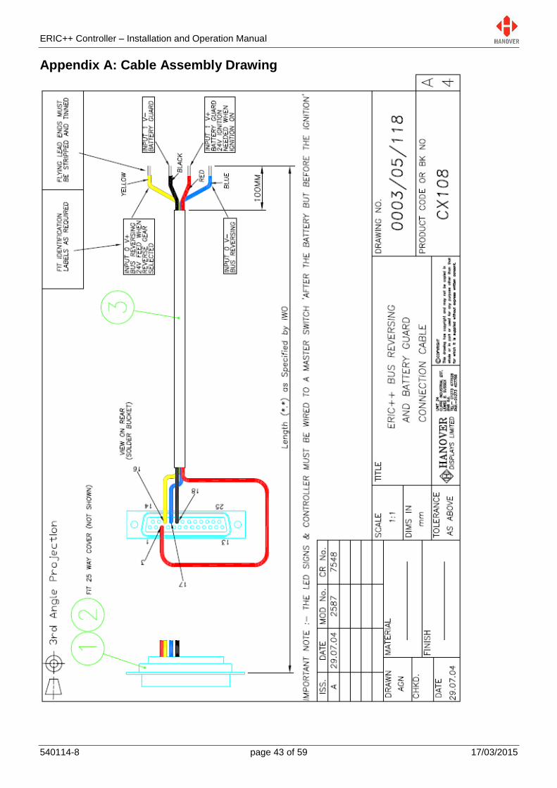
ERIC++ Controller – Installation and Operation Manual
540114-8 page 43 of 59 17/03/2015
Appendix A: Cable Assembly Drawing
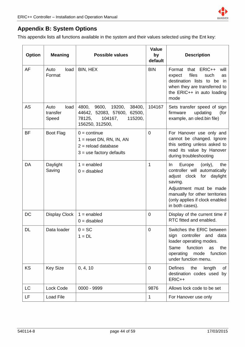
ERIC++ Controller – Installation and Operation Manual
540114-8 page 44 of 59 17/03/2015
Appendix B: System Options
This appendix lists all functions available in the system and their values selected using the Ent key:
Option Meaning Possible values
Value
by
default
Description
AF Auto load
Format
BIN, HEX BIN Format that ERIC++ will
expect files such as
destination lists to be in
when they are transferred to
the ERIC++ in auto loading
mode
AS Auto load
transfer
Speed
4800, 9600, 19200, 38400,
44642, 52083, 57600, 62500,
78125, 104167, 115200,
156250, 312500,
104167 Sets transfer speed of sign
firmware updating (for
example, an oled.bin file)
BF Boot Flag 0 = continue
1 = reset DN, RN, IN, AN
2 = reload database
3 = use factory defaults
0 For Hanover use only and
cannot be changed. Ignore
this setting unless asked to
read its value by Hanover
during troubleshooting
DA Daylight
Saving
1 = enabled
0 = disabled
1 In Europe (only), the
controller will automatically
adjust clock for daylight
saving.
Adjustment must be made
manually for other territories
(only applies if clock enabled
in both cases).
DC Display Clock 1 = enabled
0 = disabled
0 Display of the current time if
RTC fitted and enabled.
DL Data loader 0 = SC
1 = DL
0 Switches the ERIC between
sign controller and data
loader operating modes.
Same function as the
operating mode function
under function menu.
KS Key Size 0, 4, 10 0 Defines the length of
destination codes used by
ERIC++
LC Lock Code 0000 - 9999 9876 Allows lock code to be set
LF Load File 1 For Hanover use only

ERIC++ Controller – Installation and Operation Manual
540114-8 page 45 of 59 17/03/2015
LG
(ISO
639.2
codes)
Language EN - English
ES - Spanish
FR - French
IT - Italian
NL - Dutch
PT - Portuguese
RO -
Romanian
SV -
Swedish
TR - Turkish
ZH - Chinese
DA - Danish
DE - German
EN Determines the language
used by the controller (Not all
languages are programmed
into Helen by default)
MF Manual load
transfer
Format
BIN, HEX BIN Format that ERIC++ will
expect files such as
destination lists to be in
when they are transferred in
manual mode.
Note: manual loading has
been superseded by auto
loading
MS Manual load
transfer
Speed
4800, 9600, 19200, 38400,
44642, 52083, 57600, 62500,
78125, 104167, 115200,
156250, 312500,
19200 Speed that ERIC++ will
expect files such as
destination lists to be in
when they are transferred in
manual mode.
Note: manual loading has
been superseded by auto
loading
PF Profile 0 - 99 0 Controller configuration set
in Helen. For more details,
please refer to section 7 in
Helen v3.3 display-editing
software - operating manual
(ref. 540125).
SS Sign Speed AUTO, 4800, 9600, 19200,
38400
4800 Baud rate = data
transmission speed between
the controller and the signs.
Signs themselves must have
their processors set to the
same baud rate as the
controller and as each other.
The AUTO setting is rarely
used.
TU Timed
Update
1 = enabled
0 = disabled
0 Allows another controller
configuration to be uploaded
but not implemented until a
pre-determined time
ZX Factory code 0, 1 0 For Hanover use only
ZZ Factory code 00 - 99 00 For Hanover use only
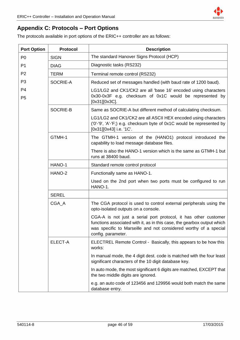
ERIC++ Controller – Installation and Operation Manual
540114-8 page 46 of 59 17/03/2015
Appendix C: Protocols – Port Options
The protocols available in port options of the ERIC++ controller are as follows:
Port Option Protocol Description
P0
P1
P2
P3
P4
P5
SIGN The standard Hanover Signs Protocol (HCP)
DIAG Diagnostic tasks (RS232)
TERM Terminal remote control (RS232)
SOCRIE-A Reduced set of messages handled (with baud rate of 1200 baud).
LG1/LG2 and CK1/CK2 are all 'base 16' encoded using characters
0x30-0x3F e.g. checksum of 0x1C would be represented by
[0x31][0x3C].
SOCRIE-B Same as SOCRIE-A but different method of calculating checksum.
LG1/LG2 and CK1/CK2 are all ASCII HEX encoded using characters
('0'-'9', 'A'-'F;) e.g. checksum byte of 0x1C would be represented by
[0x31][0x43] i.e. '1C'.
GTMH-1 The GTMH-1 version of the (HANO1) protocol introduced the
capability to load message database files.
There is also the HANO-1 version which is the same as GTMH-1 but
runs at 38400 baud.
HANO-1 Standard remote control protocol
HANO-2 Functionally same as HANO-1.
Used on the 2nd port when two ports must be configured to run
HANO-1.
SEREL
CGA_A The CGA protocol is used to control external peripherals using the
opto-isolated outputs on a console.
CGA-A is not just a serial port protocol, it has other customer
functions associated with it, as in this case, the gearbox output which
was specific to Marseille and not considered worthy of a special
config. parameter.
ELECT-A ELECTREL Remote Control - Basically, this appears to be how this
works:
In manual mode, the 4 digit dest. code is matched with the four least
significant characters of the 10 digit database key.
In auto mode, the most significant 6 digits are matched, EXCEPT that
the two middle digits are ignored.
e.g. an auto code of 123456 and 129956 would both match the same
database entry.
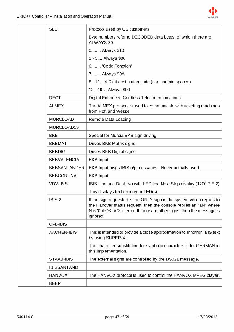
ERIC++ Controller – Installation and Operation Manual
540114-8 page 47 of 59 17/03/2015
SLE Protocol used by US customers
Byte numbers refer to DECODED data bytes, of which there are
ALWAYS 20
0........ Always $10
1 - 5.... Always $00
6........ 'Code Fonction'
7........ Always $0A
8 - 11... 4 Digit destination code (can contain spaces)
12 - 19… Always $00
DECT Digital Enhanced Cordless Telecommunications
ALMEX The ALMEX protocol is used to communicate with ticketing machines
from Hoft and Wessel
MURCLOAD Remote Data Loading
MURCLOAD19
BKB Special for Murcia BKB sign driving
BKBMAT Drives BKB Matrix signs
BKBDIG Drives BKB Digital signs
BKBVALENCIA BKB Input
BKBSANTANDER BKB Input msgs IBIS o/p messages. Never actually used.
BKBCORUNA BKB Input
VDV-IBIS IBIS Line and Dest. No with LED text Next Stop display (1200 7 E 2)
This displays text on interior LED(s).
IBIS-2 If the sign requested is the ONLY sign in the system which replies to
the Hanover status request, then the console replies an "aN" where
N is '0' if OK or '3' if error. If there are other signs, then the message is
ignored.
CFL-IBIS
AACHEN-IBIS This is intended to provide a close approximation to Innotron IBIS text
by using SUPER-X.
The character substitution for symbolic characters is for GERMAN in
this implementation.
STAAB-IBIS The external signs are controlled by the DS021 message.
IBISSANTAND
HANVOX The HANVOX protocol is used to control the HANVOX MPEG player.
BEEP

ERIC++ Controller – Installation and Operation Manual
540114-8 page 48 of 59 17/03/2015
CIBOR PROTOCOL (RS485 9600 Baud, 8 data No parity 1 stopbit)
Examples of messages including CRC bytes as sent:
1) [stx] $01 $02 $03 $04 $05 $82 $08 [etx]
2) [stx] $06 $00 $01 $81 "L010CENTRO" $69 $E4 [etx]
3) [stx] $00 $06 $01 $80 $10 $19 [etx]
CIBOR2
CIBOR3
DUBWAYF A complicated interface used especially for Dublin buses
TGX150-A Has a default config of "WF=01234" which uses the 1st 5 bytes of the
data packet as a destination code
TGX150-C Has a default config of "WF=…..0123….4" which combines 4 digit
route No and a Sense digit ('0'/'1') to form a 5 digit code ending in '0'
or '1'.
STP403S
TERNI
IBPERUGIA Message received 'yc' where c is a text message of any length.
This is very weird, somehow the route No and destination No are
extracted from this message.
PRODAT-A Process our message GLLLLSCCCCAAAA where LLLL =Line No, S
= Sense '0' or '1', CCCC = course and AAAA = Terminus No.
In this case, we form a 4 digit code from 'CCCC'.
If DestSize > 4, then leading '0's will be padded.
If DestSize < 4, then LS digits will be used.
PRODAT-B Terminate after 4 destination chars
ERG-A Process our message GLLLLSCCCCCAAAA where LLLL =Line No,
S = Sense '0' or '1', CCCC = course and AAAA = Terminus No.
In this case, we form a 5 digit code from 'CCCCC'.
If DestSize > 5, then leading '0's will be padded.
If DestSize < 5, then LS digits will be used.
ERG-C Process our message GsLLLLSCCCCCPAAAAA where s = service
status '1' = 'in service', LLLL = Line No, S = Sense '0' or '1', CCCCC =
course, P = Position and AAAAA = arret No.
In this case, we form a 5 digit code from 'CCCCC'.
If DestSize > 5, then leading '0's will be padded.
If DestSize < 5, then LS digits will be used.
Stop data is programmed at database code "NS00AAAAAP".
ERG-D

ERIC++ Controller – Installation and Operation Manual
540114-8 page 49 of 59 17/03/2015
DUHAMEL-A For customer Transdev POM. The DUHAMEL-A interface does not
respond to any messages, it just sends out the current 4 digit
destination code every 5 seconds (with STX at start and ETX at end).
NYCT
OCTA
J1708-1
J1708-2 This is the higher level (i.e L2 and above) of the J1708x protocol
J1708-2A Is J1708-2 but with special route number rendering on front sign
J1708-3
J1708-4
J1708-4A
SPEC-A Sends out the current 4 digit destination code with leading space
characters instead of zeros
SPEC-B Sends out a 10 digit code with leading zeros and can be used with
route browse
AUBAGNE Customer specific implementation
RSL
MS
VIGIE-A RS485 9600, 8, 'N', 2, False
NETNCE
GPSLOG-GPS GPS tracker P2
GPSLOG-LOG GPS tracker P3
SEMA Specialty Equipment Market Association (SEMA)
- Indicates that the port function is disabled

ERIC++ Controller – Installation and Operation Manual
540114-8 page 50 of 59 17/03/2015
Appendix D: Sign Options
This appendix lists all functions available in the sign options and their values selected by using the Ent key:
Sign
Option Values Description
S0
S1
S2
S3
S4
S5
S6
S7
S8
S9
SA
SB
SC
SD
SE
LN*
- No setting (disabled)
* Automatic assignment, i.e the switch number setting in the sign is the same
as that in the controller’s database, as determined by Helen software
0…31 The number of the sign assigned by Helen software
HANCIS/HTC Hancis (or HTC) on-board computer
This parameter should only be used if your ERIC++ has a Hancis or HTC
unit connected to the physical sign system in your vehicle.
Setting sign no. to the ‘Hancis/HTC’ value will enable the ERIC++ to
remotely control certain features of the Hancis/HTC unit. It will also add an
additional Hancis/HTC menu item under the main function menu.
EX Adverts
RN To use this feature, you have to configure a sign to be “RN”. If any signs are
configured as RN, then the ‘R’ key will be available to accept a manually
entered alphanumeric value which will be sent directly to only those signs
configured as RN.
NN To use this feature, you have to configure a sign to be “NN”. If any signs are
configured as NN, then the ‘N’ key will be available to accept a manually
entered alphanumeric value which will be sent directly to only those signs
configured as NN.
EB** 0: OFF
1: ON
When switched on, this option allows faster delivery of information to the
sign and is thus used to speed up delivery of large-sized graphic messages.
Note: It has no effect on Super-X messages, whether or not they contain
graphic images.
*LN: Internal Sign Number
**EB: Escaped Binary
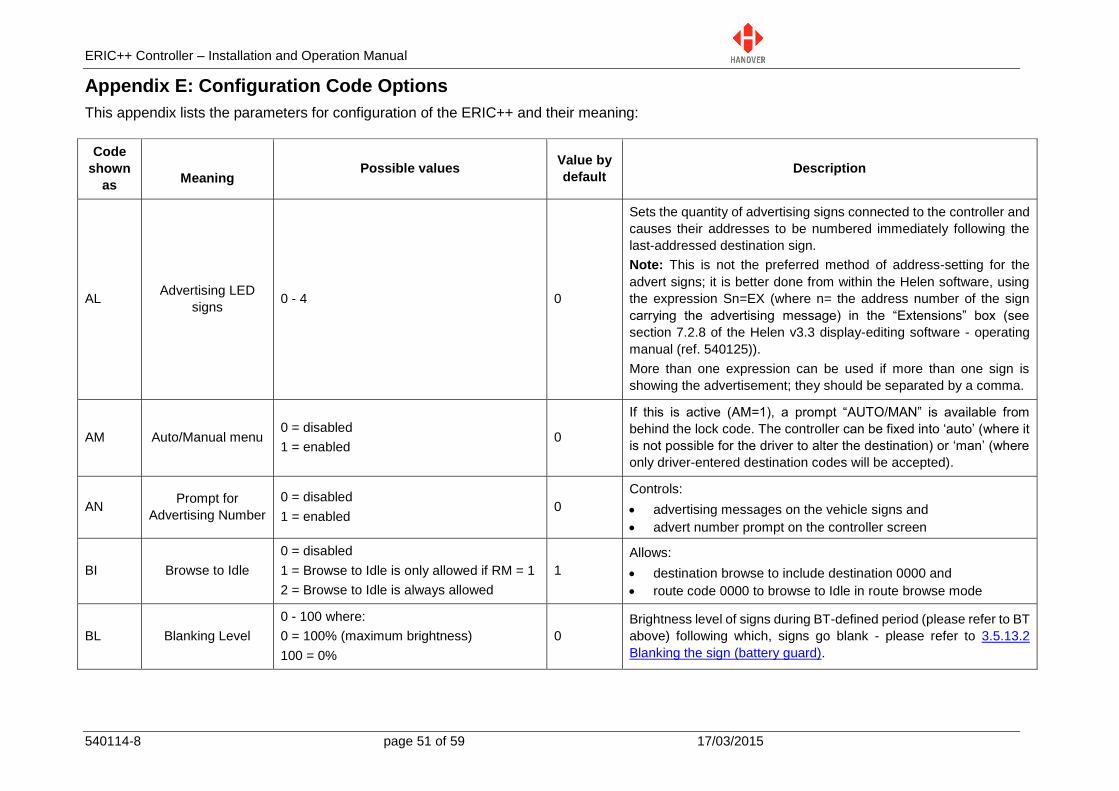
ERIC++ Controller – Installation and Operation Manual
540114-8 page 51 of 59 17/03/2015
Appendix E: Configuration Code Options
This appendix lists the parameters for configuration of the ERIC++ and their meaning:
Code
shown
as
Meaning Possible values
Value by
default Description
AL Advertising LED
signs 0 - 4 0
Sets the quantity of advertising signs connected to the controller and
causes their addresses to be numbered immediately following the
last-addressed destination sign.
Note: This is not the preferred method of address-setting for the
advert signs; it is better done from within the Helen software, using
the expression Sn=EX (where n= the address number of the sign
carrying the advertising message) in the “Extensions” box (see
section 7.2.8 of the Helen v3.3 display-editing software - operating
manual (ref. 540125)).
More than one expression can be used if more than one sign is
showing the advertisement; they should be separated by a comma.
AM Auto/Manual menu 0 = disabled
1 = enabled 0
If this is active (AM=1), a prompt “AUTO/MAN” is available from
behind the lock code. The controller can be fixed into ‘auto’ (where it
is not possible for the driver to alter the destination) or ‘man’ (where
only driver-entered destination codes will be accepted).
AN Prompt for
Advertising Number
0 = disabled
1 = enabled 0
Controls:
advertising messages on the vehicle signs and
advert number prompt on the controller screen
BI Browse to Idle
0 = disabled
1 = Browse to Idle is only allowed if RM = 1
2 = Browse to Idle is always allowed
1
Allows:
destination browse to include destination 0000 and
route code 0000 to browse to Idle in route browse mode
BL Blanking Level
0 - 100 where:
0 = 100% (maximum brightness)
100 = 0%
0
Brightness level of signs during BT-defined period (please refer to BT
above) following which, signs go blank - please refer to 3.5.13.2
Blanking the sign (battery guard).

ERIC++ Controller – Installation and Operation Manual
540114-8 page 52 of 59 17/03/2015
BR Destination
Browser
BR =0. ERIC++ runs in:
standard mode if RB = 0 or
route browse mode if RB = 1
BR = 1:
if RB = 0, ERIC++ runs in special route
browse mode: no route number is
displayed or selectable but all
destinations can be scrolled through and
selected
if RB = 1, ERIC++ runs in route browse
mode
0
Note: Do not confuse this code with that for bus reversing, which is
set as an external input option - please refer to section 3.5.13.7
Displaying ‘Bus reversing’.
BT Blanking Time 0 - 100
0
Blanking time in minutes (used with battery guard feature - please
refer to section 3.5.13.2 Blanking the sign (battery guard))
CB Confirm Browse 0 = does not prompt
1 = prompts 0
Prompts for selection confirmation when driver browses destinations
in a route
CM Canned (Vox)
Messages
0 = disabled
1 = enabled 1
If CM=1, just pressing any of the numeric keys 0-9 will cause a
hanvox play command to be sent for playing files called M0.mp3 to
M9.mp3.
DD Driver’s Display
* = use of driver's controller display text from
Helen
0 - 9, A - E = show content from selected
sign on driver’s display
* Determines what is shown on driver's controller display
DI Drivers ID 0 = disabled
1 - 5 = number of digits allowed 0
Prompt for driver's ID (i.e. PIN).
This is used by the HTC, Hancis etc: when activated, it leads to PIN
request.
ID number length is set by DI value.

ERIC++ Controller – Installation and Operation Manual
540114-8 page 53 of 59 17/03/2015
DM Display Mode
0 = use of only the top line of the controller
screen
1 = use of the top two lines of the controller
screen
T = shows time in hours, mins, secs (24h
clock) - where clock is enabled
0 Controls how driver's message is displayed on the controller screen
DN Prompt for
Destination Number
0 = no
1 = yes
1
In standard destination mode: it controls if
destination information and numbers are shown on the
passenger signs and
destination codes can be viewed and changed on the controller.
In route browse mode: this feature has no effect.
DS Destination Code
Size
3 - 6
4
Controls the size of the destination code shown on the controller
screen; it can be set from 3 to 6 digits.
DK D key for
Destination
0 = enabled
1 = disabled 1
If DK=1, the ‘D’ key must be pressed to enter the destination code as
in normal.
If DK=0, then simply pressing a numeric key 0-9 will start entering the
destination code.
This cannot work in conjunction with CM=1 or IK=0.
EI Emergency Input 0 = enabled
1 = disabled 0
Redundant feature – refer to 3.5.13.1 Emergency message.
If EI=0, then if Emergency input is activated and changes the
destination to say (for example, “CALL POLICE”), the driver’s display
on the controller will NOT change. Same feature is accomplished by
leaving the driver’s message blank when programming the ‘CALL
POLICE’ message.
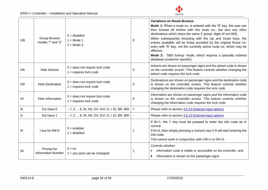
ERIC++ Controller – Installation and Operation Manual
540114-8 page 54 of 59 17/03/2015
GB Group Browse
modes ‘1’ and ‘2’
0 = disabled
1 = Mode 1
2 = Mode 2
0
Variations on Route-Browse.
Mode 1: When a route no. is entered with the ‘R’ key, the user can
then browse all entries with this route no., but also any other
destinations which share the same 3 ‘group’ digits (if not 000).
When subsequently browsing with the Up and Down keys, the
entries available will be those provided by the original Route no.
entry with ‘R’ key, not the currently active route no. which may be
different.
Mode 2: ‘SBS lookup’ mode, which requires a specially ordered
database (customer specific).
HA Hide Adverts 0 = does not require lock code
1 = requires lock code 0
Adverts are shown on passenger signs and the advert code is shown
on the controller screen. This feature controls whether changing the
advert code requires the lock code.
HD Hide Destination 0 = does not require lock code
1 = requires lock code 0
Destinations are shown on passenger signs and the destination code
is shown on the controller screen. This feature controls whether
changing the destination code requires the lock code.
HI Hide Information 0 = does not require lock code
1 = requires lock code 0
Information are shown on passenger signs and the information code
is shown on the controller screen. This feature controls whether
changing the information code requires the lock code.
I0 Ext Input 0 -, 1, 2 … 8, IN, INI, DV, DVI, E, I, EI, BR, BRI 7 Please refer to section 3.5.13 External input options
I1 Ext Input 1 -, 1, 2 … 8, IN, INI, DV, DVI, E, I, EI, BR, BRI - Please refer to section 3.5.13 External input options
IK I key for INFO 0 = enabled
1 = disabled 1
If IK=1, the ‘I’ key must be pressed to enter the info code as in
normal.
If IK=0, then simply pressing a numeric key 0-9 will start entering the
info code.
This cannot work in conjunction with CM=1 or DK=0.
IN Prompt for
Information Number
0 = no
1 = yes (and can be changed) 1
Controls whether:
information code is visible or accessible on the controller, and
information is shown on the passenger signs
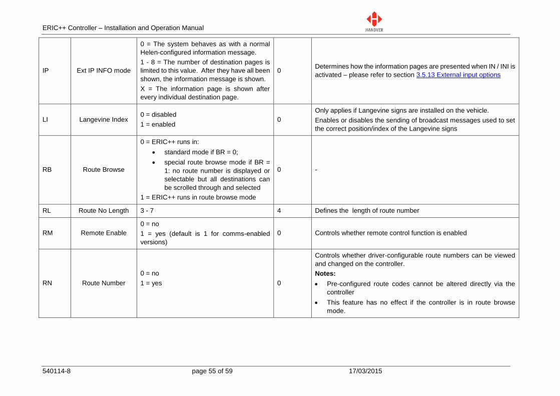
ERIC++ Controller – Installation and Operation Manual
540114-8 page 55 of 59 17/03/2015
IP Ext IP INFO mode
0 = The system behaves as with a normal
Helen-configured information message.
1 - 8 = The number of destination pages is
limited to this value. After they have all been
shown, the information message is shown.
X = The information page is shown after
every individual destination page.
0 Determines how the information pages are presented when IN / INI is
activated – please refer to section 3.5.13 External input options
LI Langevine Index 0 = disabled
1 = enabled 0
Only applies if Langevine signs are installed on the vehicle.
Enables or disables the sending of broadcast messages used to set
the correct position/index of the Langevine signs
RB Route Browse
0 = ERIC++ runs in:
standard mode if BR = 0;
special route browse mode if BR =
1: no route number is displayed or
selectable but all destinations can
be scrolled through and selected
1 = ERIC++ runs in route browse mode
0 -
RL Route No Length 3 - 7 4 Defines the length of route number
RM Remote Enable
0 = no
1 = yes (default is 1 for comms-enabled
versions)
0 Controls whether remote control function is enabled
RN Route Number
0 = no
1 = yes
0
Controls whether driver-configurable route numbers can be viewed
and changed on the controller.
Notes:
Pre-configured route codes cannot be altered directly via the
controller
This feature has no effect if the controller is in route browse
mode.
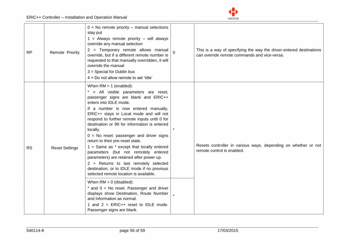
ERIC++ Controller – Installation and Operation Manual
540114-8 page 56 of 59 17/03/2015
RP Remote Priority
0 = No remote priority – manual selections
stay put
1 = Always remote priority – will always
override any manual selection
2 = Temporary remote allows manual
override, but if a different remote number is
requested to that manually overridden, it will
override the manual
3 = Special for Dublin bus
4 = Do not allow remote to set ‘Idle’
0 This is a way of specifying the way the driver-entered destinations
can override remote commands and vice-versa.
RS Reset Settings
When RM = 1 (enabled):
* = All visible parameters are reset,
passenger signs are blank and ERIC++
enters into IDLE mode.
If a number is now entered manually,
ERIC++ stays in Local mode and will not
respond to further remote inputs until 0 for
destination or 99 for information is entered
locally.
0 = No reset: passenger and driver signs
return to their pre-reset state.
1 = Same as * except that locally entered
parameters (but not remotely entered
parameters) are retained after power up.
2 = Returns to last remotely selected
destination, or to IDLE mode if no previous
selected remote location is available.
*
Resets controller in various ways, depending on whether or not
remote control is enabled.
When RM = 0 (disabled):
* and 0 = No reset. Passenger and driver
displays show Destination, Route Number
and Information as normal.
1 and 2 = ERIC++ reset to IDLE mode.
Passenger signs are blank.
*
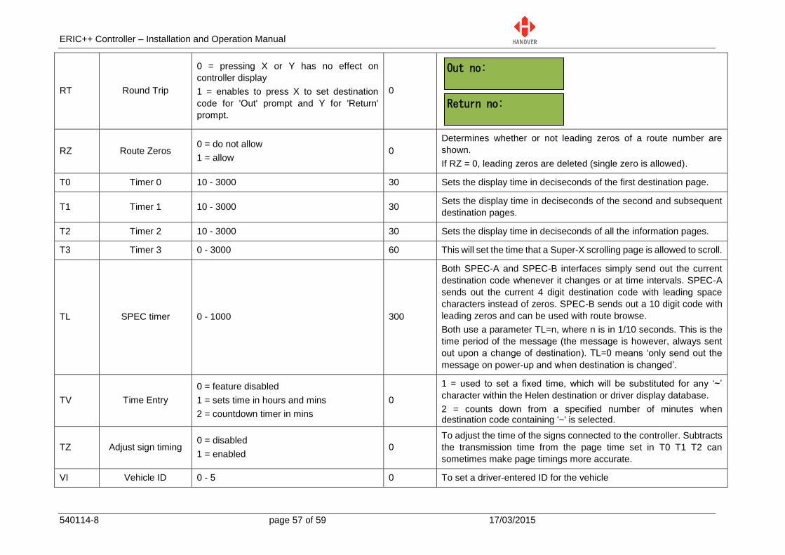
ERIC++ Controller – Installation and Operation Manual
540114-8 page 57 of 59 17/03/2015
Out no:
Return no:
RT Round Trip
0 = pressing X or Y has no effect on
controller display
1 = enables to press X to set destination
code for 'Out' prompt and Y for 'Return'
prompt.
0
RZ Route Zeros 0 = do not allow
1 = allow 0
Determines whether or not leading zeros of a route number are
shown.
If RZ = 0, leading zeros are deleted (single zero is allowed).
T0 Timer 0 10 - 3000 30 Sets the display time in deciseconds of the first destination page.
T1 Timer 1 10 - 3000 30 Sets the display time in deciseconds of the second and subsequent
destination pages.
T2 Timer 2 10 - 3000 30 Sets the display time in deciseconds of all the information pages.
T3 Timer 3 0 - 3000 60 This will set the time that a Super-X scrolling page is allowed to scroll.
TL SPEC timer 0 - 1000 300
Both SPEC-A and SPEC-B interfaces simply send out the current
destination code whenever it changes or at time intervals. SPEC-A
sends out the current 4 digit destination code with leading space
characters instead of zeros. SPEC-B sends out a 10 digit code with
leading zeros and can be used with route browse.
Both use a parameter TL=n, where n is in 1/10 seconds. This is the
time period of the message (the message is however, always sent
out upon a change of destination). TL=0 means ‘only send out the
message on power-up and when destination is changed’.
TV Time Entry
0 = feature disabled
1 = sets time in hours and mins
2 = countdown timer in mins
0
1 = used to set a fixed time, which will be substituted for any ‘~’
character within the Helen destination or driver display database.
2 = counts down from a specified number of minutes when destination code containing '~' is selected.
TZ Adjust sign timing 0 = disabled
1 = enabled 0
To adjust the time of the signs connected to the controller. Subtracts
the transmission time from the page time set in T0 T1 T2 can
sometimes make page timings more accurate.
VI Vehicle ID 0 - 5 0 To set a driver-entered ID for the vehicle
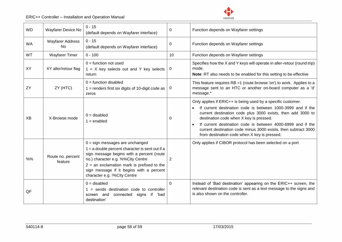
ERIC++ Controller – Installation and Operation Manual
540114-8 page 58 of 59 17/03/2015
WD Wayfarer Device No 0 - 15
(default depends on Wayfarer interface) 0 Function depends on Wayfarer settings
WA Wayfarer Address
No
0 - 15
(default depends on Wayfarer interface) 0 Function depends on Wayfarer settings
WT Wayfarer Timer 0 - 100 10 Function depends on Wayfarer settings
XY XY aller/retour flag
0 = function not used
1 = X key selects out and Y key selects
return
0
Specifies how the X and Y keys will operate in aller-retour (round trip)
mode.
Note: RT also needs to be enabled for this setting to be effective
ZY ZY (HTC)
0 = function disabled
1 = renders first six digits of 10-digit code as
zeros
0
This feature requires RB =1 (route browse 'on') to work. Applies to a
message sent to an HTC or another on-board computer as a 'd'
message.*
XB X-Browse mode 0 = disabled
1 = enabled 0
Only applies if ERIC++ is being used by a specific customer.
If current destination code is between 1000-3999 and if the
current destination code plus 3000 exists, then add 3000 to
destination code when X key is pressed.
If current destination code is between 4000-6999 and if the
current destination code minus 3000 exists, then subtract 3000
from destination code when X key is pressed.
%% Route no. percent
feature
0 = sign messages are unchanged
1 = a double percent character is sent out if a
sign message begins with a percent (route
no.) character e.g. %%City Centre
2 = an exclamation mark is prefixed to the
sign message if it begins with a percent
character e.g. !%City Centre
2
Only applies if CIBOR protocol has been selected on a port
QF
0 = disabled
1 = sends destination code to controller
screen and connected signs if ‘bad
destination’
0 Instead of ‘Bad destination’ appearing on the ERIC++ screen, the
relevant destination code is sent as a text message to the signs and
is also shown on the controller.
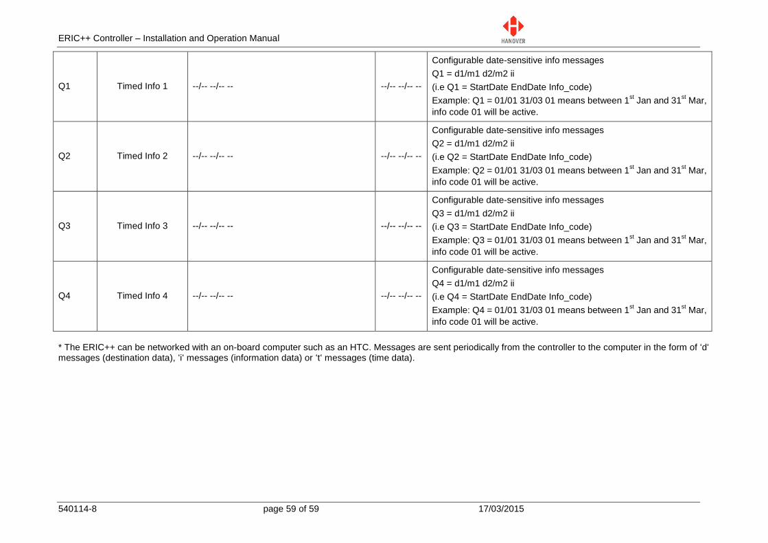
ERIC++ Controller – Installation and Operation Manual
540114-8 page 59 of 59 17/03/2015
Q1 Timed Info 1 --/-- --/-- -- --/-- --/-- --
Configurable date-sensitive info messages
Q1 = d1/m1 d2/m2 ii
(i.e Q1 = StartDate EndDate Info_code)
Example: Q1 = 01/01 31/03 01 means between 1st Jan and 31
st Mar,
info code 01 will be active.
Q2 Timed Info 2 --/-- --/-- -- --/-- --/-- --
Configurable date-sensitive info messages
Q2 = d1/m1 d2/m2 ii
(i.e Q2 = StartDate EndDate Info_code)
Example: Q2 = 01/01 31/03 01 means between 1st Jan and 31
st Mar,
info code 01 will be active.
Q3 Timed Info 3 --/-- --/-- -- --/-- --/-- --
Configurable date-sensitive info messages
Q3 = d1/m1 d2/m2 ii
(i.e Q3 = StartDate EndDate Info_code)
Example: Q3 = 01/01 31/03 01 means between 1st Jan and 31
st Mar,
info code 01 will be active.
Q4 Timed Info 4 --/-- --/-- -- --/-- --/-- --
Configurable date-sensitive info messages
Q4 = d1/m1 d2/m2 ii
(i.e Q4 = StartDate EndDate Info_code)
Example: Q4 = 01/01 31/03 01 means between 1st Jan and 31
st Mar,
info code 01 will be active.
* The ERIC++ can be networked with an on-board computer such as an HTC. Messages are sent periodically from the controller to the computer in the form of ‘d‘ messages (destination data), ‘i‘ messages (information data) or ‘t‘ messages (time data).