installation and operation manual -...
TRANSCRIPT

401 Millcreek Road, Box 649Marietta, Ohio 45750USAPhone: 740-373-4763Toll Free: 800-848-3080FAX: 740-373-4189
Manual P/N 3177877Rev I Dated 29OCT09
Installation and Operation Manual
Microprocessor-ControlledGeneral Purpose Water Baths
Models280 (2825/2826), 281 (2829/2830), 282 (2833/2834),283 (2837/2838), 284 (2841/2842), 285 (2845/2846),
286 (2849/2850) and 288 (2853/2854)
���������������� ���������������������
�����������������������������������������������
���������������������� �����!
�����������"����#�����������������������������������
������������������������������������
$""
$�
%������$�
���������
���
�� �������������!
&���������������'��
�����������������������
������������������������������������������������������������� �
������������������������������������������������������ �

NOTICE
THE MATERIAL IN THIS MANUAL IS FOR INFORMATION PURPOSES ONLY. THE CONTENTS AND THEPRODUCT IT DESCRIBES ARE SUBJECT TO CHANGE WITHOUT NOTICE. THERMO SCIENTIFIC MAKESNO REPRESENTATIONS OR WARRANTIES WITH RESPECT TO THIS MANUAL. IN NO EVENT SHALLTHERMO BE LIABLE FOR ANY DAMAGES, DIRECT OR INCIDENTAL, ARISING OUT OF OR RELATED TOTHE USE OF THIS MANUAL.
For repair information or replacement parts assistance from the manufacturer,call Technical Services using our toll free telephone number.
800-438-4851(FAX) 740-373-4189
NOTE:
THE 240V UNITS DESCRIBED IN THIS MANUAL WERE DESIGNED SPECIFICALLY FOR THE EUROPEANMARKET AND ARE SUPPLIED WITH A EUROPEAN STYLE POWER CORD. FOR DOMESTIC USE, A U.S.STYLE POWER CORD (P/N: 3176836) MUST BE ORDERED SEPARATELY.
Table 3.1 Listing of Models Included in this Manual
ModelNumber
CatalogNumber
Electrical Characteristics Capacity240V UnitsMains Fuse
Volts Watts Amps Liters Gallons
2825/2826
31666863166687
120240
2251.91
1.5 0.4 FST-5x20-1.0A
2829/2830
31666883166689
120240
2251.91
2.5 0.7 FST-5x20-1.0A
2833/2834
31666903166691
120240
3002.51.3
5.5 1.5 FST-5x20-2.0A
2837/2838
31666923166693
120240
4003.31.7
12.0 3.2 FST-5x20-2.0A
2841/2842
31666943166695
120240
6005
2.619.5 5.2 FST-5x20-3.15A
2845/2846
31666963166697
120240
6005
2.618.0 4.9 FST-5x20-3.15A
2849/2850
31666983166699
120240
1200105.2
43.0 11.4 FST-5x20-6.3A
2853/2854
31667003166701
120240
8006.73.5
12.0* 3.2* FST-5x20-3.15A
* Each chamber
For all 240V models: Power Supply Board Fuse - FST-5x20-6.3mA

Initial release12/98A
INDEX DATE AMENDED PAGES NOTES
REVISION STATUS
Pictorial update of wiring perECO JGC000223A
02/00B 17
updated electrical secificationsC 07/01 2,8,9,12,17
D
E
F
G
H
I
NOV01
4/05
5/06
1/08
9/08
10/09
Add caution "acidic & caustic substance"
new manual #, manufacture location
consolidated with the 240V manual3177693, updated specs
Added warning not to operate withoutwater in the bath.
Revised water specifications
temp performance with gable only
5
36100112 (340016400)
ECR 23443 & 23496
ECR 24361
ECR 24808
ECR25795/BA-684

Contents
1. Introduction..................................................................................................................... 1
2. Unpacking and Damage ................................................................................................ 1
3. General Information ........................................................................................................ 2
4. Performance Data ........................................................................................................... 3
5. Installation ....................................................................................................................... 3
6. Explanation of Controls ................................................................................................. 4
7. Operation......................................................................................................................... 5
8. Maintenance .................................................................................................................... 6
9. Troubleshooting ............................................................................................................. 7
10. Parts Replacement ..................................................................................................... 10
11. Replacement Parts List .............................................................................................. 12
12. Assembly and Schematic Drawings ......................................................................... 14
13. Warranty ...................................................................................................................... 19

1
2.0 UNPACKING AND DAMAGE
2.01 This product was carefully packed andthoroughly inspected before leaving ourfactory. Save all packing material if apparatusis received damaged.
2.02 Responsibility for safe delivery was assumedby the carrier upon acceptance of theshipment; therefore, claims for loss or damagesustained in transit must be made upon thecarrier by the recipient as follows:
Visible Loss or Damage: Note any externalevidence of loss or damage on the freight billor express receipt, and have it signed by thecarrier's agent. Failure to adequately describesuch external evidence of loss or damagemay result in the carrier's refusing to honoryour claim. The form required to file suchclaim will be supplied by the carrier.
Concealed Loss or Damage: Concealedloss or damage is any loss or damage whichdoes not become apparent until themerchandise has been unpacked andinspected. Should either occur, make a writtenrequest for inspection by carrier's agent within15 days of the delivery date; then file a claimwith the carrier.
2.03 If you follow the above instructions carefully,Thermo will guarantee our full support of yourclaim to be compensated for loss or damagein transit.
DO NOT — for any reason — return thisunit to Thermo without first obtainingreturn authorization. In any correspondencewith Thermo, please supply the nameplatedata, including catalog number and serialnumber.
1. 0 INTRODUCTION
1.01 Your satisfaction and safety are important toThermo and a complete understanding of thisunit is necessary to attain these objectives.
1.02 As the ultimate user of this apparatus, youhave the responsibility to understand its properfunction and operational characteristics. Thisinstruction manual should be thoroughly readand all operators given adequate trainingbefore attempting to place this unit in service.Awareness of the stated cautions andwarnings, and compliance with recommendedoperating parameters — together withmaintenance requirements—are importantfor safe and satisfactory operation. The unitshould be used for its intended application;alterations or modifications will void thewarranty.
WARNING AS A ROUTINE LABORATORY PRECAUTION,ALWAYS WEAR SAFETY GLASSES WHENWORKING WITH THIS APPARATUS.
1.03 This product is not intended, nor can it beused, as a sterile or patient connected device.In addition, this apparatus is not designed foruse in Class I, II, or III locations as defined bythe National Electrical Code.

2
3.0 GENERAL INFORMATION
3.01 Precision Baths are widely used in researchand quality control. Their superb temperatureuniformity and stability makes them especiallydesirable for legal or reference tests.
CAUTIONDO NOT APPLY POWER TO THE WATER BATHBEFORE FILLING THE WATER BATH PAN WITHTHE RECOMENDED WATER SOLUTION (SEESECTION 7.02). OPERATING THE BATHWITHOUT A WATER SOLUTION COULD RESULTIN OVERHEATING AND DAMAGE TOT HEHEATER.
3.02 The microprocessor control panel houses allfunctions necessary to operate the bath.The push-button keys and single displaywindow allows the operator to adjust bathtemperature and temperature calibration viaa single set of controls.
3.03 The Proportional Integral Derivative (PID)temperature control allows precisetemperature control. Use of the gable coverprovided is required to maintain optimaltemperature sensitivity.
3.04 A high limit temperature cutout is provided inthe event of an empty water bath. If the sensorreads a temperature 5°C higher than the settemperature, a high temperature cutout willoccur indicated by a display reading of "EEE,"and the heater will be inhibited from operating.To reset the bath, the power must be turnedoff and then back on again. The high limittemperature cutout is internally set for 5°Cabove any set temperature and can not be setby the user.
3.05 The interior of the bath is constructed ofstainless steel and is designed for operationwith distilled water or water solutions, suchas water ethylene glycol with corrosioninhibitor's added. The body is made fromgalvanized steel and is painted for addedprotection. A gable cover is also providedwith the bath.
3.06 The 240-volt units are identical in appearanceto the 120-volt units.
NOTE:USING CHLORINATED TAP WATER OR ADDITIVESTHAT CONTAIN CHLORINE WILL VOID THEMANUFACTURER'S WARRANTY. SIMILARLY, HIGHPURITY (DEIONIZED) WATER THAT DOES NOT FALLWITHIN THE RESISTIVITY RANGE OF 50K TO 1MOHM AND THE PH RANGE FROM 7 TO 9 WILL VOIDTHE WARRANTY. CONTACT TECHNICAL SERVICESWITH ANY QUESTIONS.

3
5.02 Electrical Connections -
WARNINGFOR PERSONAL SAFETY, THIS APPARATUS MUSTBE PROPERLY GROUNDED.
1. The power cord provided on this unit isequipped with a three-prong (grounding) plugwhich mates with standard three-pronggrounding wall receptacle to minimize thepossibility of electric shock hazard from thisapparatus. If in doubt the user should have thewall receptacle and circuit checked by aqualified electrician to make sure thereceptacle can provide adequate current andis properly grounded.
2. Where a standard two-prong wall receptacleis encountered, it is the personal responsibilityand obligation of the user to have it replacedwith a properly grounded three-prong wallreceptacle. Do not, under anycircumstances, cut or remove the third(ground) prong from the power cord. Donot use a two-prong adapter plug.
5.03 Determine the total amount of current beingused by other apparatus connected to thecircuit that will be used for this apparatus. Itis critical that the added current demand (seenameplate) of this and other equipment usedon the same circuit does not exceed therating of the fuse or circuit breaker.
Environmental Conditions-This instrument is designed to operate safely underthe following conditions:
• Indoor Use Only• Temperature: 5° to 40° C• Maximum Relative Humidity: 80% for
temperatures to 22°C• Maximum Altitude 2000 meters
Maximum performance is assured across thefollowing temperature range:
• 15ºC to 45ºC
CAUTION• BE SURE THAT THE POWER SUPPLY IS OF THESAME VOLTAGE AS SPECIFIED ON NAMEPLATE.
• BE SURE THAT THE WALL RECEPTACLE ISREADILY IDENTIFIABLE AND EASILY REACHEDTO DISCONNECT UNIT FROM POWER SOURCE.
DIFFUSER PANLEG EXTENSION KIT
4.0 PERFORMANCE DATA
4.01 The following performance specificationsfor bath models 280 through 288 are valid onlywhen the gable cover is in place.
Control sensitivity @ 37C = ±0.1CTemperature uniformity @ 37C = ±0.2CMinimum bath temperature = Ambient +5CMaximum bath temperature
5.0 INSTALLATION
WARNINGINSTALLATION SHOULD BE COMPLETED BYQUALIFIED PERSONNEL ONLY.
5.01 1. The most uniform operating conditions andresults will be obtained by placing the bath ona level surface in an area remote from drafts,ventilating outlets, radiators, and other rapidlychanging ambient conditions.
2.Place the stainless steel metal shelf(corners facing downward) inside the bathchamber. The shelf (Diffuser Pan) providesa sample base and protects samples fromtouching the hot metal bath bottom. If it isnecessary to increase the height of the diffuserpan, a Leg Extension Kit is included for thispurpose, except for the Model 2829/2830.Following the figure shown below, attach the4 extension legs to each of the four corners ofthe diffuser pan.
4
Place ce rtifie d / trace ab le the rmome ter into hold e r.
Pre ss ENTER - calib ration is com ple te .Press or to match r ead out to the rmomete r.
Off
On
ENTER
Pre ss Calib rate b utton.
Allow to s tab ilize .
Should Ca lib ra tion Be Req uire d :
Disp lay will the n re turn to actual tem p erature .Pre ss ENTER - Ne w Se t Point is acce p te d .Pre ss or until d es ire d te mp e rature is d isp layed .
Calib rate
He ate r On
To Se t Te mp erature :
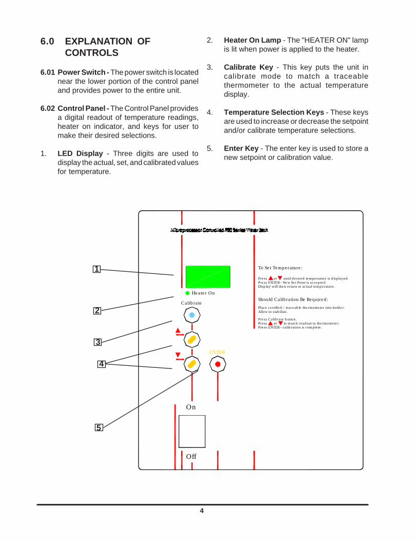
6.0 EXPLANATION OFCONTROLS
6.01 Power Switch - The power switch is locatednear the lower portion of the control paneland provides power to the entire unit.
6.02 Control Panel - The Control Panel providesa digital readout of temperature readings,heater on indicator, and keys for user tomake their desired selections.
1. LED Display - Three digits are used todisplay the actual, set, and calibrated valuesfor temperature.
2. Heater On Lamp - The "HEATER ON" lampis lit when power is applied to the heater.
3. Calibrate Key - This key puts the unit incalibrate mode to match a traceablethermometer to the actual temperaturedisplay.
4. Temperature Selection Keys - These keysare used to increase or decrease the setpointand/or calibrate temperature selections.
5. Enter Key - The enter key is used to store anew setpoint or calibration value.
1
2
3
4
5
5
7.0 OPERATION
CAUTION:EXERCISE CARE WHEN USING ACIDIC ORCAUSTIC SOLUTIONS AS THEY WILL ATTACKTHE GALVANIZED STEEL BATH BODY IF SPILLEDINTO THE BATH. IF SPILLS DO OCCUR, THEBATH LIQUID SHOULD BE IMMEDIATELYDRAINED AND THE UNIT THOROUGHLYFLUSHED. SPILLS AND CONDENSATION SHOULDBE CLEANED/REMOVED FROM ALL METALSURFACES AFTER EACH USE.
7.01 When filling the bath with water, allowancemust be made for the displacement of waterupon immersion of samples. The maximumliquid level is 1 inch below the top of the pan.
7.02 To conserve energy, reduce evaporation,increase temperature control accuracy, andreach/maintain 100°C, use the gable coverprovided. Do not use aluminum foil as acover, as it may cause corrosion due to anelectrochemical reaction.
1. Add distilled water to bath. The water levelshould be no closer than 1" from the top of thebath when the bath is fully loaded. NOTE:Use sterile distilled water only. Theacceptable resistivity range is 50K to 1Mohms (conductivity 1 to 20 mico Siemens).The acceptable pH range is 7 to 9.
2. Power up: Depress the power switch locatedat the lower end of the control panel.Immediately after turning on power, all of thesegments of the display will be on along withthe HEATER ON indicator. After 3 seconds,the current set temperature will be displayedand this will last for 5 seconds. Then thedisplay will change to the actual bathtemperature.
3. To display the set temperature, quickly pressthe /\ (up) or \/ (down) key. The current settemperature will be displayed. After 5 seconds,the display will return to the actual bathtemperature.
4. To change the set temperature, continuouslypress the /\ or \/ key until the desired settemperature is displayed. When continuouslypressing either the /\ or \/ keys, the displaychanges slowly at first but after 1 degree haspassed, the display begins to change rapidly.After the desired set temperature is achieved,then press the ENTER key. The display withthe new set temperature will flash three timesand then it will return to the bath temperature.
If the ENTER key is NOT pressed, theexpected new set temperature will not beaccepted and the water bath will control at theprevious set temperature.
5. The water baths are calibrated at the factoryfor use over a wide range of temperatures.Due to non-linearities in the control system, itmay be necessary to make the display matcha calibrated thermometer's reading, eventhough the difference might be only a fewtenth's of a degree.
The calibrate function should be used only tomatch a STABLE bath's actual temperatureto the calibrated thermometer.
To perform calibration, press the CALIBRATEkey. The display changes to CAL, then flashesback to bath temperature. This occurs fourtimes, if no other keys are pressed, then itresumes displaying the bath temperature.
After inserting a calibrated thermometer intothe holder and letting it stabilize for a minimumof 15 minutes, note its reading.
Press the CALIBRATE key once again andwhile the display is flashing, press either the/\ or \/ key to make the display match the notedthermometer reading. After the desired displayis achieved, press the ENTER key. The displayflashes three times with the adjusted reading,then stops flashing. The bath is now calibratedmore accurately for the control set point.
WARNINGEXPLOSION, IMPLOSION OR THE RELEASEOF TOXIC OR FLAMMABLE GASES ARISINGFROM THE MATERIAL BEING HEATED IS THESOLE RESPONSIBILITY OF THE USER.
6
8.0 MAINTENANCE
8.01 Cleaning and care of stainless steel: Stainlesssteel will resist corrosion; however, it is notimpervious to it. For maximum life, stainlesssteel must receive a certain amount of care.
CAUTIONAVOID SPILLING HARSH CHEMICALS ONTO THEBATH, AS CORROSION OF THE STAINLESSSTEEL MAY RESULT.
1. There are many chemical cleaners, but usuallyjust changing the water and periodic cleaningwith mild soapy water or a non-scratchingscouring power will suffice.
Should algae or other undesirablemicroorganisms form on the top of the bathmedia, add a little formaldehyde or zephiranchloride to alleviate this problem.
CAUTIONELECTROLYSIS CAN DAMAGE STAINLESS STEEL.THIS CAN OCCUR IF AN OBJECT IS ALLOWED TOREST DIRECTLY ON THE SURFACE, TRAPPINGMOISTURE THAT BECOMES OXYGEN STARVEDBUT IS SURROUNDED BY WATER CONTAININGOXYGEN. THE RESULTING ELECTROLYTIC ACTIONWILL PIT OR ERODE THE STAINLESS STEEL.
2. Should it be necessary to use a media otherthan water such as those listed below, limitthe time to a maximum of four hours. Cleansurfaces immediately after use.
Aluminum Chloride Barium ChlorideBichloride of Mercury Calcium ChlorideCarbolic Acid Chlorinated LimeCitric Acid (boiling) Dakin's SolutionFerrous Chloride Mercury SaltsLysolMercuric Chloride PhenolPotassium Permanganate Stanous ChlorideSodium Hypochlorite Tartaric AcidPotassium Thiocyanate
3. Should the stainless steel ever becomediscolored by iron rust, use the followingprocedure to remove all traces of the rust andrestore the stainless steel.
WARNINGALWAYS OBSERVE THE FOLLOWING SAFETYPRECAUTIONS! USE HEAVY GLOVES OR OTHERADEQUATE HAND PROTECTION. WEAR GOGGLESOR OTHER ADEQUATE EYE PROTECTION. WORKONLY IN AREAS WITH ADEQUATE VENTILATION.
Prepare a solution of 20% nitric and 1.5%hydrochloric acid (if preferred, a 2% to 5%solution of warm oxalic acid may be used).Swab solution over surface, allowing it toremain until all rust is loosened. This willusually take 1 to 2 minutes.
As soon as rust is loosened, immediatelyflush with clean water until all acid is removed.Dry thoroughly.
4. During operation, quite a bit of condensationforms on the inside of the gable cover. Whenremoving the gable cover, have one of itscorners centered above the water bath, sothat the water runoff goes into the bath.Shaking the cover aids the water runoff. Besure to wipe up any water spillage on oraround the bath.
IMPORTANTTHE USER HAS THE RESPONSIBILITY FORCARRYING OUT THE APPROPRIATEDECONTAMINATION IF HAZARDOUS MATERIAL ISSPILLED ON OR INSIDE THE BATH.
CAUTIONNEVER USE THE FOLLOWING CHEMICALS:AQUA REGIA FERRIC CHLORIDE IODINESODIUM AZIDE SULFURIC ACID

7
Troubleshooting Procedures
Problem Procedure
9.02 The following is a list of the tools andinstruments required to perform theprocedures outlined in the TroubleshootingProcedures table.
Suggested Tools:
• Phillips Screwdriver• 7/16" Socket or adjustable wrench• Ohmmeter• DC Voltmeter• AC Voltmeter• 5VDC Power Supply• Nut Driver 11/32"
9.0 TROUBLESHOOTING
WARNINGSERVICE SHOULD BE PERFORMED BY A QUALIFIEDTECHNICIAN. BEFORE REPLACING ANYELECTRICAL OR MECHANICAL COMPONENTS,UNPLUG THE LINE CORD. IF ELECTRICAL POWERIS REQUIRED FOR SERVICE, USE EXTREME CARE.
9.01 Refer to Troubleshooting Procedures Table(9.03 through 9.06) for troubleshootinginformation on the baths. This table providesthe basic information required to repair thebath.
9.03 No Heat 1. Verify that setpoint temperature is greater than the actualwater temperature.
2. Check temperature probe.A. Disconnect unit from electrical supply.B. Disconnect temperature probe connector J5 from Control
Board.C. Place 5 volt DC between Pins 1 & 3 on temperature probe
connector.D. Place a voltmeter between Pins 2 & 3 on temperature
probe connector. Place the temperature probe in a bathof known temperature. Verify that the output voltage ofthe temperature probe approximately corresponds to thevalues in the table below.
Degrees Centigrade vs. Output Voltage of TemperatureProbe
Temp °C Vout Temp °C Vout0 320mV 60 1.400V10 500mV 70 1.580V20 680mV 80 1.760V30 860mV 90 1.940V40 1.040V 99.9 2.218V50 1.220V
8
9.03 No Heat (cont.)
Troubleshooting ProceduresProblem Procedure
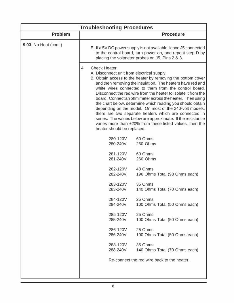
E. If a 5V DC power supply is not available, leave J5 connectedto the control board, turn power on, and repeat step D byplacing the voltmeter probes on J5, Pins 2 & 3.
4. Check Heater.A. Disconnect unit from electrical supply.B. Obtain access to the heater by removing the bottom cover
and then removing the insulation. The heaters have red andwhite wires connected to them from the control board.Disconnect the red wire from the heater to isolate it from theboard. Connect an ohm meter across the heater. Then usingthe chart below, determine which reading you should obtaindepending on the model. On most of the 240-volt models,there are two separate heaters which are connected inseries. The values below are approximate. If the resistancevaries more than ±20% from these listed values, then theheater should be replaced.
280-120V 60 Ohms280-240V 260 Ohms
281-120V 60 Ohms281-240V 260 Ohms
282-120V 48 Ohms282-240V 196 Ohms Total (98 Ohms each)
283-120V 35 Ohms283-240V 140 Ohms Total (70 Ohms each)
284-120V 25 Ohms284-240V 100 Ohms Total (50 Ohms each)
285-120V 25 Ohms285-240V 100 Ohms Total (50 Ohms each)
286-120V 25 Ohms286-240V 100 Ohms Total (50 Ohms each)
288-120V 35 Ohms288-240V 140 Ohms Total (70 Ohms each)
Re-connect the red wire back to the heater.

9
9.06 No Display
9.05 Too much heat
Troubleshooting ProceduresProblem Procedure
9.04 Unstable temperature control
5. Check TRIAC (High voltage output of control board)A. Make sure power is disconnected from the unit.B. Connect an AC voltmeter across the heater capable of
reading 120 or 240 volts, depending on your particular unit.C. Turn power on and select a set point higher than the actual
temperature to get the HEATER ON indicator to illuminate.With the HEATER ON indicator lit, there should be either120 or 240 volts across the heater. If not, the control boardshould be replaced.
1. Use gable cover provided to improve temperature control.
2. Verify that temperature setpoint is set at desired value.
3. If control is stable, but not at desired temperature, check settemperature or perform calibration (Paragraph 7.0, Step 5).
4. Check Temperature Probe (see Paragraph 9.03, Step 2).
1. Check Temperature Probe (see Paragraph 9.03, Step 2).
2. Check TRIAC (see Paragraph 9.03, Step 5).
1. Verify that the water bath is plugged in.
2. Verify that Power switch is in the on position.
3. Disconnect unit from the electrical supply, gain access to thecontrol board and check Fuse 1 located near the transformeron the control board.

10
10.0 PARTS REPLACEMENT
WARNINGBEFORE REPLACING ANY PART, BE SURE BATH ISDISCONNECTED FROM POWER SOURCE. SERVICESHOULD BE PERFORMED BY A QUALIFIEDTECHNICIAN.
10.01 Before removing any parts for replacement,verify part in question by following theinstructions listed in the troubleshootingguide.
10.02 Refer to Parts Replacement Table below forappropriate replacement procedures. Failureto follow parts replacement procedures maycause damage to the bath.
1. Remove the necessary screws to remove the bottom panfrom underneath the water bath. Then remove the insulationnecessary to view the temperature sensor and its orientationwhen connected to the control board.
2. Disconnect the sensor from the control board at J5.
3. The temperature sensor is mounted to the pan with a steel clamp.Loosen the nut that holds the clamp which in turn holds the sensorin place. Note that the sensor has its flat side against the pan. Wheninstalling a new sensor, it is important to do the same.
4. Reverse the procedure to install the new sensor.
5. Recalibrate the water bath with the new sensor. See Section7.0 Operation, Step 5.
1. Remove the necessary screws to remove the bottom panfrom underneath the water bath. Then remove the insulationnecessary to gain access to the heater(s).
2. Disconnect the wires that are attached to the heaters.
3. Using a 11/32" nut driver, remove the nuts that hold theheater brackets in place.
4. Replace the heater(s), heater brackets, and re-attach the wires.
1. Remove the necessary screws to remove the bottom panfrom underneath the water bath. Then remove the insulationnecessary to gain access to the control board, and hex nutswhich hold the bath pan to the body.
Parts Replacement
10.04 Replace Heater
10.05 *Replace Control Board
10.03 Replace Temperature Sensor

11
Parts Replacement (cont.)
2. Disconnect the wires that are attached to the heater.Then disconnect the temperature sensor from J5 on thecontrol board.
3. Remove the bath pan from the body by removing each11/32" nut from each corner of the pan. NOTE: Model2849/2850 has 6 hex nuts which hold the pan in place.
4. Disconnect J1 and J2 from the control board.
5. Remove the 4 nuts that support the board. Remove thecontrol board and replace it, then reverse this procedure.
10.05 Replace Control Board (cont.)
10.06 Replace Diffuser Pan LegExtension
1. Attach the four extension legs to each of the four cornersof the diffuser pan using the nut, splitwasher and screwprovided. Refer to figure shown on page 3 of thismanual.
*CAUTIONWhen replacing the Control Board #3176801, note the following:
1. For 120 Volt models, JP3 and JP4 must be installed.2. For 240 Volt models, JP3 and JP4 must be removed.

12
11.0 Replacement Parts List
120-Volt Models
2825 2829 2833 2837 2841 2845 2849 2853
Pan 3177554 3177576 3177572 3177573 3177577 3177574 3177578 3177573
Diffuser Plate Asm. 3163798 3163797 3163798 3163801 3163799 3163805 3163804 3163801
PCB Asm. 3176801
Heater 3175493 3175493 3175494 3175495 3175496 3175496 3175496 3175495
Heater Harness 3176805
Power Harness 3176807
Temp. ProbeAssembly
3177640
Heater Insulator 3177733 3177733 3177734 3177735 3177736 3177736 3177736 3177735
On/Off Switch 3175318
Leg Extension Kit 3161440
Line Cord 3178034
Gable Cover 3166202 3161572 3166202 3166203 3166206 3166217 3166218 3166203
240-Volt Models
2826 2830 2834 2838 2842 2846 2850 2854
Pan 3177554 3177576 3177572 3177573 3177577 3177574 3177578 3177573
Diffuser Plate Assy. 3163798 3163797 3163798 3163801 3163799 3163805 3163804 3163801
PCB Assy. 3176801
Heater 3175487 3175487 3175476 3175477 3175478 3175478 3175478 3175477
Heater Harness 3176806
Power Harness 3176808
Temp. Probe Assy. 3177640
Heater Insulator 3177733 3177733 3177734 3177735 3177736 3177736 3177736 3177735
On/Off Switch 3175318
Leg Extension Kit 3161440
Line Cord 3176551
Mains Fuse 3172453 3172453 3172461 3172461 3172442 3172442 3172449 3172442
Controller PCB Fuse 3175929
Gable Cover 3166202 3161572 3166202 3166203 3166206 3166217 3166218 3166203

13
12.0 ASSEMBLY & SCHEMATIC DRAWINGS
Pre
ss C
alib
rate
bu
tton
.
To
Se
t Te
mp
era
ture
:
Pre
ss E
NT
ER
- c
alib
rati
on is
co
mp
l ete
.Pr
ess
or
to m
atch
re
ado
ut t
o th
erm
omet
er.
Plac
e c
ert
ifie
d /
trac
eab
le th
erm
omet
er
into
ho
lde
r.
Sho
uld
Cal
ibra
tio
n B
e R
equ
ire
d:
Dis
pla
y w
ill t
he
n re
turn
to a
ctua
l te
mp
erat
ure
.Pr
ess
EN
TE
R -
New
Se
t Po
int
is a
cce
pte
d.
Pre
ss
o
r
un
til
de
sir e
d t
em
per
atur
e is
dis
pla
yed
.
Off
On
EN
TE
R
He
ate
r O
n
Cal
ibra
te
All
ow to
sta
bil
ize.
DE
TA
IL "
A"
BO
TT
OM
CO
VE
R
TY
PIC
AL
F
RO
NT
V
IEW
PO
WE
R S
WIT
CH
PA
NB
AT
H B
OD
Y
14
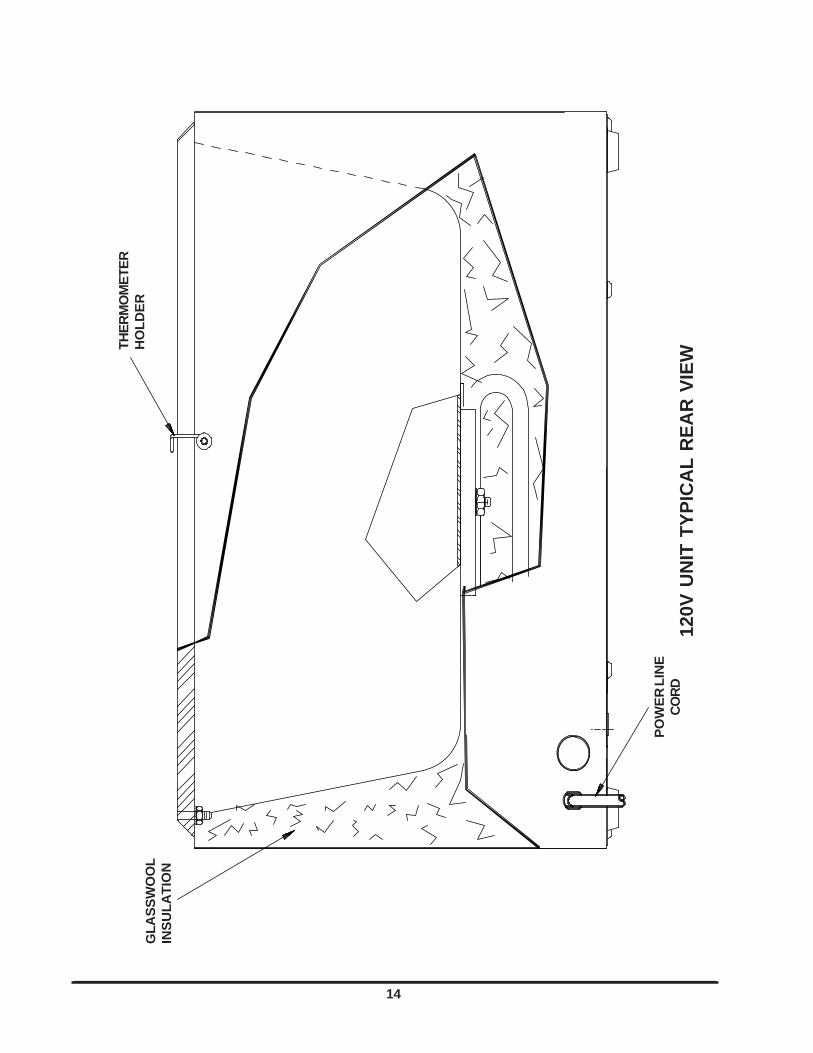
120V
UN
IT T
YP
ICA
L R
EA
R V
IEW
GL
AS
SW
OO
LIN
SU
LA
TIO
N
TH
ER
MO
ME
TE
RH
OL
DE
R
PO
WE
R L
INE
CO
RD
15
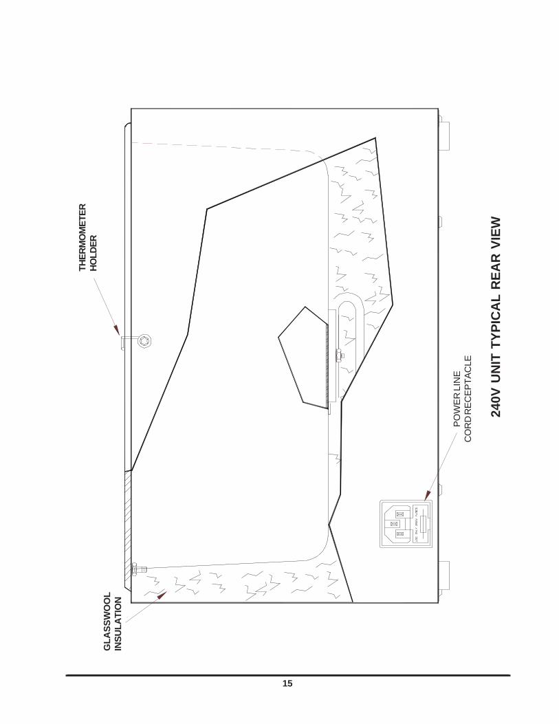
240V
UN
IT T
YP
ICA
L R
EA
R V
IEW
GL
AS
SW
OO
LIN
SU
LA
TIO
N
TH
ER
MO
ME
TE
RH
OL
DE
R
PO
WE
R L
INE
CO
RD
RE
CE
PT
AC
LE

16
ON/OFFSWITCH
PCB ASSEMBLY
120V UNIT TYPICAL BOTTOM VIEW
POWERHARNESS
HEATERHARNESS
HEATER
HEATERINSULATOR
POWER LINE CORD
THE FLAT SIDE OF THESENSOR MUST COME INCONTACT WITH THE PAN
TEMPERATUREPROBE ASSEMBLY

17
ON/OFFSWITCH
PCB ASSEMBLY
240V UNIT TYPICAL BOTTOM VIEW
POWERHARNESS
HEATERHARNESS
HEATER
HEATERINSULATOR
POWER LINE CORD
THE FLAT SIDE OF THESENSOR MUST COME IN
CONTACT WITH THE PAN
TEMPERATUREPROBE ASSEMBLY

18
TEMPERATURE SENSOR
POWER LINE CORD
DETAIL "A"
POWERHARNESS
PCBASSEMBLY
HEATERHEATERHARNESS
POWERSWITCH
120 VAC WIRING DIAGRAM
NOTE: JP3 & JP4 MUST BE INSTALLED FOR 120 VAC OPERATION.

19
NOTE: JP3 & JP4 MUST BE REMOVED FOR 240VAC OPERATION
240 VAC WIRING DIAGRAM
POWER LINE CORD
POWERSWITCH
TEMPERATURE SENSOR
PCBASSEMBLY
HEATERHARNESS
HEATER
POWERHARNESS
DETAIL "A"
POWERRECEPTACLEWITH FUSES
20
TH
ER
MO
FIS
HE
R S
CIE
NT
IFIC
STA
ND
AR
D P
RO
DU
CT
WA
RR
AN
TY
The W
arr
anty
Period s
tart
s tw
o w
eeks fro
m the d
ate
your
equip
ment is
ship
ped fro
m o
ur
facili
ty. T
his
allo
ws for
ship
pin
g tim
e
so t
he w
arr
anty
will
go i
nto
effect
at
appro
xim
ate
ly t
he s
am
e t
ime y
our
equip
ment
is d
eliv
ere
d.
The w
arr
anty
pro
tection
exte
nds t
o a
ny s
ubsequent
ow
ner
during t
he f
irst
year
warr
anty
period.
Du
rin
g t
he
first
ye
ar,
co
mp
on
en
t part
s p
rove
n t
o b
e n
on
-co
nfo
rmin
g in
ma
teria
ls o
r w
ork
ma
nsh
ip w
ill b
e r
epaire
d o
r re
pla
ce
d
at
Therm
o's
expense,
labor
inclu
ded.
Insta
llation a
nd c
alib
ration a
re n
ot
covere
d b
y t
his
warr
anty
agre
em
ent. T
he T
echnic
al
Serv
ices D
epart
ment
must
be conta
cte
d fo
r w
arr
anty
dete
rmin
ation and direction prior
to perf
orm
ance of
any re
pairs.
Expendable
ite
ms,
gla
ss,
filters
and g
askets
are
exclu
ded f
rom
this
warr
anty
.
Repla
cem
ent
or
repair o
f com
ponents
part
s o
r equip
ment
under
this
warr
anty
shall
not
exte
nd t
he w
arr
anty
to e
ither
the
equip
ment or
to the c
om
ponent part
beyond the o
rigin
al w
arr
anty
period. T
he T
echnic
al S
erv
ices D
epart
ment m
ust giv
e p
rior
appro
val
for
retu
rn o
f any c
om
ponents
or
equip
ment. A
t T
herm
o's
option,
all
non-c
onfo
rmin
g p
art
s m
ust
be r
etu
rned t
o
Therm
o F
ish
er
Scie
ntific p
osta
ge p
aid
and r
epla
cem
ent
part
s a
re s
hip
ped F
OB
destination.
TH
IS W
AR
RA
NT
Y IS
E
XC
LU
SIV
E A
ND
IN
L
IEU
O
F A
LL
O
TH
ER
W
AR
RA
NT
IES
, W
HE
TH
ER
W
RIT
TE
N,
OR
AL
O
R
IMP
LIE
D.
NO
WA
RR
AN
TIE
S O
F M
ER
CH
AN
TA
BIL
ITY
OR
FIT
NE
SS
FO
R A
PA
RT
ICU
LA
R P
UR
PO
SE
SH
AL
L A
PP
LY.
Therm
o s
hall
not
be l
iable
for
any i
ndirect
or
consequential
dam
ages i
nclu
din
g,
without
limitation,
dam
ages r
ela
ting t
o l
ost
pro
fits
or
loss o
f p
rod
ucts
.
Your
local
Therm
o S
ale
s O
ffic
e i
s r
eady t
o h
elp
with c
om
pre
hensiv
e s
ite p
repara
tion i
nfo
rmation b
efo
re y
our
equip
ment
arr
ives.
Printe
d instr
uction m
anuals
care
fully
deta
il equip
ment
insta
llation,
opera
tion a
nd p
reventive m
ain
tenance.
If e
quip
ment
serv
ice
is r
equired,
ple
ase c
all
your
Technic
al S
erv
ices D
epart
ment
at
1-8
00-4
38-4
851 (
US
A a
nd C
anada)
or
1-7
40-3
73-4
763. W
e're r
eady to a
nsw
er
your
questions o
n e
quip
ment w
arr
anty
, opera
tion, m
ain
tenance, serv
ice a
nd s
pecia
l
applic
ation.
Outs
ide t
he U
SA
, conta
ct
your
local dis
trib
uto
r fo
r w
arr
anty
info
rmation.
Rev.
4
4/0
9
ISO
9001
REGI
STER
ED

21
TH
ER
MO
FIS
HE
R S
CIE
NT
IFIC
IN
TE
RN
AT
ION
AL
DE
AL
ER
WA
RR
AN
TY
Th
e W
arr
an
ty P
erio
d s
tart
s t
wo
mo
nth
s f
rom
th
e d
ate
yo
ur
eq
uip
me
nt
is s
hip
pe
d f
rom
ou
r fa
cili
ty.
Th
is a
llow
s f
or
sh
ipp
ing
tim
e s
o t
he
wa
rra
nty
will
go
in
to e
ffe
ct
at
ap
pro
xim
ate
ly t
he
sa
me
tim
e y
ou
r e
qu
ipm
en
t is
de
live
red
. T
he
wa
rra
nty
pro
tec-
tio
n e
xte
nd
s t
o a
ny s
ub
se
qu
en
t o
wn
er
du
rin
g t
he
first
ye
ar
wa
rra
nty
pe
rio
d.
De
ale
rs w
ho
sto
ck o
ur
eq
uip
me
nt
are
allo
we
d
an
ad
ditio
na
l six
mo
nth
s fo
r d
eliv
ery
an
d in
sta
llatio
n, p
rovid
ed
th
e w
arr
an
ty c
ard
is c
om
ple
ted
an
d r
etu
rne
d to
th
e T
ech
nic
al
Se
rvic
es D
epa
rtm
en
t.
Du
rin
g th
e first ye
ar,
co
mp
on
en
t pa
rts p
rove
n to
be
no
n-c
on
form
ing
in
ma
teria
ls o
r w
ork
ma
nsh
ip w
ill b
e r
epa
ire
d o
r re
pla
ce
d
at T
he
rmo
's e
xp
en
se
, la
bo
r e
xclu
de
d. In
sta
llatio
n a
nd
ca
libra
tio
n a
re n
ot co
ve
red
by th
is w
arr
an
ty a
gre
em
en
t. T
he
Te
ch
nic
al
Se
rvic
es D
epa
rtm
en
t m
ust
be
co
nta
cte
d f
or
wa
rra
nty
de
term
ina
tio
n a
nd
dire
ctio
n p
rio
r to
pe
rfo
rma
nce
of
an
y r
epa
irs.
Exp
en
da
ble
ite
ms,
gla
ss,
filte
rs,
rea
ge
nts
, tu
bin
g,
an
d g
aske
ts a
re e
xclu
de
d f
rom
th
is w
arr
an
ty.
Re
pla
ce
me
nt
or
repa
ir o
f co
mp
on
en
ts p
art
s o
r e
qu
ipm
en
t u
nd
er
this
wa
rra
nty
sh
all
no
t e
xte
nd
th
e w
arr
an
ty t
o e
ith
er
the
eq
uip
me
nt o
r to
th
e c
om
po
ne
nt pa
rt b
eyo
nd
th
e o
rig
ina
l wa
rra
nty
pe
rio
d. T
he
Te
ch
nic
al S
erv
ice
s D
epa
rtm
en
t m
ust g
ive
prio
r
ap
pro
va
l fo
r re
turn
of
an
y c
om
po
ne
nts
or
eq
uip
me
nt.
At
Th
erm
o's
op
tio
n,
all
no
n-c
on
form
ing
pa
rts m
ust
be
re
turn
ed
to
Th
erm
o p
osta
ge
pa
id a
nd
re
pla
ce
me
nt
pa
rts a
re s
hip
pe
d F
OB
de
stin
atio
n.
TH
IS W
AR
RA
NT
Y I
S E
XC
LU
SIV
E A
ND
IN
LIE
U O
F A
LL
OT
HE
R W
AR
RA
NT
IES
, W
HE
TH
ER
WR
ITT
EN
, O
RA
L O
R
IMP
LIE
D.
NO
WA
RR
AN
TIE
S O
F M
ER
CH
AN
TA
BIL
ITY
OR
FIT
NE
SS
FO
R A
PA
RT
ICU
LA
R P
UR
PO
SE
SH
AL
L A
PP
LY
.
Th
erm
o s
ha
ll n
ot
be
lia
ble
fo
r a
ny in
dire
ct
or
co
nse
qu
en
tia
l d
am
ag
es in
clu
din
g,
with
ou
t lim
ita
tio
n,
da
ma
ge
s r
ela
tin
g t
o lo
st
pro
fits
or
loss o
f p
rod
ucts
.
Yo
ur
loca
l T
he
rmo
Sa
les O
ffic
e i
s r
ea
dy t
o h
elp
with
co
mp
reh
en
siv
e s
ite
pre
pa
ratio
n i
nfo
rma
tio
n b
efo
re y
ou
r e
qu
ipm
en
t
arr
ive
s.
Prin
ted
in
str
uctio
n m
an
ua
ls c
are
fully
de
tail
eq
uip
me
nt
insta
llatio
n,
op
era
tio
n a
nd
pre
ve
ntive
ma
inte
na
nce
.
Co
nta
ct
yo
ur
loca
l d
istr
ibu
tor
for
wa
rra
nty
in
form
atio
n.
We
’re
re
ad
y t
o a
nsw
er
yo
ur
qu
estio
ns o
n e
qu
ipm
en
t w
arr
an
ty,
op
er-
atio
n,
ma
inte
na
nce
, se
rvic
e a
nd
sp
ecia
l a
pp
lica
tio
n.
Rev.
4
2/0
9
ISO
9001
REGI
STER
ED
