installation and operating instructions - condair.co.uk · created: 07.02.2008 changed: 11.08.2011...
TRANSCRIPT

DRAABE Industrietechnik GmbH Tel.: +49 40 853277-0 Commerzbank AG Sitz der Gesellschaft: Hamburg Schnackenburgallee18 Fax: +49 40 853277-79 BLZ: 200 400 00 Konto: 040 113 5900 Registergericht: Hamburg HRB 36575 D-22525 Hamburg E-Mail: [email protected] Deutsche Bank AG Gerichtsstand: Hamburg Geschäftsführer: Tomas Kleitsch Internet: www.draabe.de BLZ: 200 700 00 Konto: 065 082 6100 Umsatzsteuer-ID-Nr.: DE 118 544 017
Installation and Operating Instructions
Air Humidifier System
HighPur: HPS200 HPS3200 HumCenter HumSpot HumPower Type TF 4 Type TF 8.1 Type TF 8.2 Type TF 16 Type TF 32 NanoFog Evolution

Created: 07.02.2008 Changed: 11.08.2011 Printed: 11.08.2011 - 2 -
Contents Air humidifier system Page
1. Introduction 4
1.1 Getting started 4 1.2 Notes on the technical documentation 4 2. For your safety 5
3. Product overview 7
3.1 TF system variants 7 3.1.1 Humidifying one zone with NanoFog Evolution, TF8.1 7 3.1.2 Humidifying two zones with 8 3.2 System description 9 3.2.1 Description of function of High Pressure System (HighPur) 10 3.2.2 Description of function of HumCenter 13 3.2.3 Description of function of atomisers TF4, TF8.1, TF8.2, TF16 15 3.2.4 Description of function of atomiser TF32 16 3.2.5 Description of function of NanoFog Evolution 17 3.2.6 Description of function of HumSpot 18 3.2.7 Description of function of HumPower 21 3.2.8 Description of function of maximum hygrostat 21 4. Planning bases 22 4.1 Notes on planning an air humidifier system in one zone 22
4.1.1 Example 1 (TF4, TF8.1) 22 4.1.1.1 Calculation of maximum humidification output 22 4.1.1.2 Definition of equipment requirement 23 4.1.2 Example 2 (TF8.2, TF16) 24 4.1.2.1 Calculation of maximum humidification output 24 4.1.2.2 Definition of equipment requirement 25 4.1.3 Example 3 (TF32) 26 4.1.3.1 Calculation of maximum humidification output 26 4.1.3.2 Definition of equipment requirement 26 4.2 Notes on planning an air humidifier system in two zones 27
4.2.1 Example 4 (TF16 and TF32) 27 4.2.1.1 Calculation of maximum humidification output 27 4.2.1.2 Definition of equipment requirement 28 4.3 Notes on water supply 29 4.3.1 Untreated water (drinking/mains water) requirements 29 4.3.2 Requirements for a water treatment system 29 5. Installation 30
5.1 Safety instructions for installation 30 5.2 General instructions for placement 30 5.3 General instructions for installation 31 5.3.1 Mounting console HighPur 32 5.3.2 HumSpot and maximum hygrostat 33 5.3.3 HumPower 34 5.3.4 Atomisers TF4, TF8.1, TF8.2, TF16 35 5.3.5 Atomiser TF32 36 5.3.6 Atomiser NanoFog Evolution 38 5.3.7 High-pressure tubing 40
Created: 07.02.2008 Changed: 11.08.2011 Printed: 11.08.2011 - 3 -
5.3.8 Pressure testing of high-pressure tubing 41 5.4 Electrical installation 42 5.4.1 High Pressure System (HighPur) 42 5.4.2 HumCenter 43 5.4.2.1 HighPur to HumCenter bus connection 44 5.4.2.2 Zone bus connection 45 5.4.2.3 Zone and container collective alarm 46 5.4.2.4 BMS connection 47 5.4.3 HumSpot 49 5.4.4.1 Connections between HumSpots 50 5.4.4.2 Connecting an external hygrostat/BMS 52 5.4.4.3 Connecting the HumPower 53 5.4.4.4 Connection for external maximum hygrostat 54 5.4.4 Atomisers TF4, TF8.1, TF8.2, TF16 55 5.4.5 Atomiser TF32 55 5.4.6 Atomiser NanoFog Evolution 56 5.5 Material specifications 58 5.5.1 High-pressure circuit 58 5.5.2 Electrical components 59 6. Operation 59
6.1 Shutdown in daily operation 59 6.2 Startup in daily operation 60 6.3 Checks 60 7. Replacing components 62
7.1 High Pressure System (HighPur) 62 7.2 Atomisers TF 4, TF8.1, TF8.2, TF16 63 7.3 Atomiser TF 32 64 7.4 Atomiser NanoFog Evolution 65 8. Technical data 66
8.1 High Pressure System (HighPur) 66 8.2 HumCenter 66 8.3 Atomisers TF4, TF8.1, TF8.2, TF16, TF32 67 8.4 Atomiser NanoFog Evolution 67 8.5 HumSpot 67 8.6 HumPower 68 8.7 Maximum hygrostat 68 9. Appendix 69
9.1 Accessories/spare parts 69 9.2 h,x diagram 70 9.3 Fresenius Test Certificate 71 9.4 Declaration of conformity 72
Created: 07.02.2008 Changed: 11.08.2011 Printed: 11.08.2011 - 4 -
1. Introduction
1.1 Getting started
Thank you for choosing the DRAABE air humidifier system.
The air humidifier system is of state-of-the-art design, and conforms to the generally recog-nised rules relating to safety. Nevertheless, users and/or third parties may be at risk, and/or property may be damaged, if the systems are not used correctly. In order to ensure safe, correct and cost-effective operation, you should therefore be sure to take note of all the information and follow all the safety instructions set out in this techni-cal documentation. If you have any queries about matters which are not dealt with in this document, or if you need more details, please contact your local DRAABE regional distributor, or call our Ser-vice Hotline (+49 40 85 32 77-19). They will be glad to help.
1.2 Notes on the technical documentation
Limitations
This technical documentation deals with the DRAABE air humidifier system. The system components, such as the High Pressure System, the atomiser, etc., are described only to the extent necessary to ensure correct and proper use. As the system offers extensive ex-pansion options, this document focuses on the base system. Various components are available depending on the application and the required performance level. A higher hu-midification output influences various system components. Accessories are available which are not an essential part of the system, while others form part of a standard configuration. For more information on accessories and custom solutions refer to the customer-specific schematic or contact DRAABE Hamburg.
The information presented in this technical documentation is limited to:
- planning of a air humidifier system.
- installation, startup, operation and servicing of the air humidifier
system.
The technical documentation is supplemented by a range of separate documents (bro-chures, order forms, schematic diagrams etc.). Where necessary, the technical documenta-tion also provides cross-references to such other documents.
Created: 07.02.2008 Changed: 11.08.2011 Printed: 11.08.2011 - 5 -
Notational conventions
This symbol identifies safety and danger notices which must be observed in order to
avoid possible injury and/or damage to property. Safety and danger notices are also indi-cated by the word CAUTION.
This symbol identifies items of important information. They are also indicated by the word IMPORTANT.
This symbol is to be found on the rating plates of all units (High Pressure System, atomiser etc.). It prompts you to read through the technical documentation before carrying out any
action on the unit. If you have any queries after reading through the technical documenta-tion, consult the manufacturers' Technical Service department before carrying out any ac-
tion. Safekeeping
Please keep the technical documentation in a safe place, where it will be readily to hand at all times. If you lose the documentation please contact DRAABE Hamburg. Language versions
This technical documentation is available in various languages. Please contact DRAABE Hamburg for details.
2. For your safety
Regulation use
The air humidifier system is intended only for controlled humidification of enclosed rooms under the specified operating conditions in non-explosive environments. Any other
use is classified as not in keeping with the designated purpose, and may cause the system to pose a hazard. Regulation use also means observance of and compliance with all information and in-structions contained in this manual (in particular the safety instructions) and strict con-
formance to the operating conditions. General safety instructions
- The air humidifier system may only be installed and operated by per-sonnel who are familiar with the product and are adequately quali-fied to carry out the assigned work. It is incumbent upon the customer
to ensure that the technical documentation is supplemented by in-house instructions regarding the duty of supervision and notification, work organisation, personnel qualification, etc.
- Before beginning work on components of the air humidifier system shut the system down correctly, as described in section 6.2, and se-
cure it against unintentional restart. - Follow all local safety regulations:
relating to the handling of mains powered electrical and electronic equipment.
relating to the design and construction of water and high-pressure compressed air systems.
!

Created: 07.02.2008 Changed: 11.08.2011 Printed: 11.08.2011 - 6 -
- Poorly maintained air humidifier systems may pose a danger to health.
Consequently, maintenance intervals must be observed and main-tenance work must be performed correctly.
- If it is to be assumed that safe operation is no longer possible, the
air humidifier system must be immediately shut down and secured against unintentional restarting, and DRAABE must be notified. This
may be the case under the following circumstances:
if system components are damaged.
if the system is no longer working correctly.
if connection fittings or lines are leaking.
- The High Pressure System of the air humidifier system is IP00 pro-tected. Make sure the unit is protected against water dripping and splashing at its place of installation.
- The HumSpot and HumCenter are IP30 protected. Make sure the unit
is protected against water splashing at its place of installation.
- CAUTION If the air humidifier system is installed in a room with no wa-
ter drain, water sensors with automatic shut-off valves must be in-stalled in the room to safely close off the water in the event of a mal-function in the water supply system.
- To prevent water damage, you should not store any materials which
are sensitive to water directly underneath the High Pressure System or the atomisers.
- CAUTION Risk of corrosion! To prevent damage, no corrosion-
sensitive components should be placed in the vicinity of the aerosol mist. The specified clearances underneath and in front of the atomis-ers must be maintained (see section 5).
- The air humidifier system may only be operated with treated water.
Drinking water, well water or rain water is not suitable. Nor must the system be operated with de-ionised water (see also section 4.3).
- Depending on the mineral content of the pure water (generated by the
water softener and reverse osmosis process), mineral deposits of varying severity may form in the vicinity of the aerosol mist.
- Sensitive materials and equipment should be protected accordingly or
removed from the vicinity.
- No other actions other than the work specified in this manual should be performed on the air humidifier system.
- Use only original DRAABE accessories and spares.
- No modifications may be made to the air humidifier system without the
written consent of DRAABE.
- In the event of modifications to the system, an acceptance test must be performed by DRAABE Service or by personnel authorised by DRAABE prior to restarting.

Created: 07.02.2008 Changed: 11.08.2011 Printed: 11.08.2011 - 7 -
3. Product overview
3.1 System variants
The system is highly flexible. The custom system setups are oriented to the required level of humidification, the room situation and the requirements specific to the concerned indus-try. The main differences are embodied in the "humidifying one zone", and "humidifying two zones" variants. A zone is characterised in that the room air humidity in the said zone is recorded by a hy-grostat (HumSpot) and is conditioned within that limited area. In a two zone system, the air humidifiers of the two zones are recorded separately and conditioned individually. A High Pressure System (referred to as HighPur in the following) offers the facility to condition multiple zones in a distributed system. Points to note in sys-tem planning:
- At least one TF32 atomiser, two TF16/TF8.1/TF8.2 atomisers, four TF4 atomisers or four NanoFog Evolution atomisers must be connected to one HighPur, to safeguard a minimum water consumption.
- If the above requirement cannot be fulfilled in an exceptional case, make sure that the high-pressure loop is at least 50 metres long.
- The capacity of the HighPur must not be exceeded.
3.1.1 Humidifying one zone with NanoFog Evolution, TF8.1 The minimum configuration (see below: System view) comprises a HumSpot,
a High Pressure System (in the following named " HighPur ") and two TF8.1 or four NanoFog Evolution atomisers. The HighPur delivers the operating pres-sure of approximately 85 bar (1.232 psi). It has a maximum delivery of 200kg/h. A maximum of ten TF8.1 or NanoFog Evolution atomisers can be connected to one HumPower. This is due to the fact that a reliable measure-ment of the humidity (by HumSpot) is difficult to achieve with too large groups. Several small groups provide a more homogeneous humidification of a very extensive zone.
IMPORTANT: For notes on the humidification output refer to section 4: "Plan-
ning bases". The HumSpot controls the entire system. It includes a humidity sensor which
measures the humidity of the zone being conditioned. It is also used to preset the desired humidity. For details of the function and equipment specification of the HumSpot see "Description of function of HumSpot“.

Created: 07.02.2008 Changed: 11.08.2011 Printed: 11.08.2011 - 8 -
System view
High pressure system HighPur
Pure water
HumPower
39.0
HumSpot
HumCenter
TF8.1
NanoFog
3.1.2 Humidifying of two zones
The minimum configuration (see below: System view) comprises two HumSpot, one Hum-center, one HighPur and the atomisers. IMPORTANT: For notes on the humidification output refer to section 4: "Planning bases".
A DRAABE remote fault indicator system can be connected to the HighPur as an option (see description of function: "DRAABE remote fault indicator“). The HumSpot controls the entire system. It includes a humidity sensor which measures the humidity of the zone being conditioned. It is also used to preset the desired humidity. For details of the function and equipment specification of the HumSpot see "Description of func-tion of HumSpot“.

Created: 07.02.2008 Changed: 11.08.2011 Printed: 11.08.2011 - 9 -
System view
High pressure system HighPur
Pure water
Atomiser Turbo Fog
Atomisier NanoFog Evolution
HumCenter
HumPower
HumPower
39.0 39.0
HumSpots
3.2 System description
The DRAABE air humidifier system is a state-of-the-art monopropellant jet air humidifier system, offering the highest comfort and economy. The water is atomised by a special swirl nozzle with a very small orifice. The practically silent and absolutely non-drip atomisation is attained by a high-pressure system (HighPur). The basic system layout is shown in the diagram (see sections 3.1.1 to 3.1.4). The system is configured according to the specific application and required performance level. A range of system components are available which differ primarily in their performance specifications (e.g. pure water output, humidifi-cation output). A higher performance level of individual components may influ-ence the selection of other system components (e.g. water softener, high-pressure system) and their installation and operation. Dual and triple systems can be constructed, and additional accessories can be installed.

Created: 07.02.2008 Changed: 11.08.2011 Printed: 11.08.2011 - 10 -
3.2.1 Description of function of High Pressure System (HighPur)
Power supply 400VAC, 3 phases
HumCenter
Water feed High-pressure outlet
drain High-pressure return
The HighPur generates a pulsating hydraulic water flow. The pump is driven by an electric motor and generates an operating pressure of approximately 85 bar (1.232 psi). From the HighPur, the water is fed into a ring main (high-pressure outlet). From the ring main the in-dividual atomisers are supplied by way of stubs. The ring main terminates back at the HighPur (high-pressure return). All internal HighPur processes are handled by a programmed control (PLC). The HumCenter and HumSpot are connected to the HighPur by way of the bus cable at equipment socket 4 (see page 12). If no humidification is required over a protracted period of time there is a risk of bacterial contamination due to standstill. To prevent this, both the HighPur and the HumSpot are fit-ted with an automatic fresh water system. The automatic fresh water system of the HighPur routes the water out of the ring main by way of a bioreactor. The bioreactor eliminates bacterial contamination from the water by means of UV-C radiation. CAUTION: The automatic fresh water system constitutes an essential component of the
system for hygienic reasons. Make sure that power and water supply are permanently available. CAUTION: Regular maintenance/checks are essential to guarantee hygienic operation.
Make sure that maintenance/checks are registered and performed by the manufacturer or by authorised/trained staff. CAUTION: The performance of the bioreactor must be checked every six to nine months. If
this is not possible it must be replaced. Only the original DRAABE bioreactor must be used. Failure to comply with this instruction may be harmful to health, as safe elimination of bac-terial contamination can no longer be guaranteed. The function of the HighPur is presented on the following based on the combined flow/circuit diagram (page 12).The display of the HighPur indicates the function states based on a stylised flowchart and LEDs.
barbar
400 V 3~
Ein/Aus
Vordruck
Zulauf
Mindes tdruckBetrieb
Entlastung
BioSafeLec kage
Störung
Wirk ungs überwac hte
UV-C Entkeimung
Elek tronis che
Sicherhei tsk ontrol le
Automatis ierte Fris chwas serfunktion
Aus beute 100%
Modem -Schnittstelle
Anbindung Gebäudetec hnik
Xx HUM Temp Status

Created: 07.02.2008 Changed: 11.08.2011 Printed: 11.08.2011 - 11 -
BioSafeLeckage
MindestdruckInlet pressure
Inlet
Minimum PressureOperation
Relief
BioSafeLeakage
Fault
A humidification request is transmitted directly to the PLC. The HighPur starts up. Once the operating pressure of 85 bar has been reached the HumSpot is notified of the fact and it ac-tivates the atomisers. The "Operating“ and "BioSafe“ LEDs on the HighPur light up. As soon as the pump is running, the supply pressure, motor current and operating pressure are continuously monitored. The illuminated power switch additionally indicates that the power is connected to the HighPur and the unit is on. Water is fed to the HighPur through the inlet. The inlet pressure switch monitors the pres-sure and shuts down the system if the water supply is interrupted. In this case the red "Inlet Pressure" LED on the display lights up. The unloader ensures a virtually constant operating pressure. The operating pressure is also monitored by a pressure switch (minimum pressure). If the minimum pressure switch registers an infringement of a minimum limit (while the pump is running), the PLC shuts down the system and signals a fault by way of the red "Min. Pressure" LED. If the operating pressure rises too high it is limited by the mechanical combi valve. No fault is indicated. In-stead, the water flows out of the bypass into the discharge. If a leak occurs within the unit (because of a burst tube for example) the unit shuts down and the red "Leakage" LED lights up. Whenever the HighPur shuts off, whether because the presetting has been reached or because of a fault, the pressure relief solenoid valve immediately reduces the pressure in the HighPur and in the ring main system. This process takes a few seconds. CAUTION: To be sure the pressure in the tubing system (and in the ring main system) has
fallen, check the two manometers on the mounting console. Only when both indicate 0 bar (0 psi) has the pressure been reduced to a safe level. The HighPur is installed in a portable mini container. The container is placed on the wall bracket. Flexible, self-retracting tubes connect the system to the mounting console. They are simply detached from the console to replace the unit. This container system permits the HighPur to be removed and returned to the manufacturer for a thorough service at intervals of 6 to 8 months. The container system ensures maxi-mum operating reliability and rapid assistance in case of faults.

Created: 07.02.2008 Changed: 11.08.2011 Printed: 11.08.2011 - 12 -
M
L1
24
S/S
COM 0
COM 1
COM 2
COM 3
COM 4
X0 X1 X2 X3 X4 X5 X6 X7 X10X11X12X13N0
0V Y0 Y1 Y2 Y3 Y4 Y5 Y6 Y7
For hirers of the high-pressure system, the provision of a replacement unit, the service support, the necessary replacement of wearing parts and the routine servicing are free of charge. Flow diagram of the HighPur
High pressure pump MV DS inlet Inlet pressure Combi valve DS Min. pressure MV Pressure regulator Relief (Unloader) High pressure Inlet Drain Return feed
Electric diagram of the high pressure system (HighPur)
CEEform power plug (male) 400VAC, 3 phases Motor Motor Motor Softstart Contactor protector N 5x1,5mm
2
L1 Power- PE switch From equipment socket3, PIN PE L2 Inlet pressure switch L3 Min. pressure switch SI1 SI2 From motor protector SI1: Fuse outputs Service SI2: Fuse PLC SI3: Fuse display Fan A: to UV board PLC B: to equipm.socket3, PIN 1 C: to equipm.socket3, PIN 2 D: to equipm.socket3, PIN 3
E: 24VDC display SI3 A B C D Display E MV inlet Leakage sensor MV relief Equipm. socket3
MMagnetic valve : MV, Pressure switch: DS

Created: 07.02.2008 Changed: 11.08.2011 Printed: 11.08.2011 - 13 -
3.2.2 Description of HumCenter function
The HumCenter is the central control unit for the air humidification system. The entire air humidification system is connected to the HumCenter using a bus system. The central con-trol unit monitors and transfers data between the humidification zones and the units.
The HumCenter consists of a display and several function keys which can be used to move between, select and edit the separate points on the menu. This function is described below. Please find a detailed description of the different menu points and their parameters in the HumDigital operating instructions.
Use the fixed-value function keys to get an overview of the zones, containers, alarms and the HumCenter. Using the "UP/DOWN" keys, select a zone, container or alarm. The keys can also be used to scroll down the screen to show other information which cannot be seen on the screen. Further functions are available using the softkeys below the display. Zone menu
The zone menu shows all zones (HumSpot) connected to the bus with the current relative room humidity, temperature and status. When a zone is selected, the softkeys can be used to call up a detailed status report or change the zone settings.
UP/DOWN keys to select and
scroll
LED indicator Memory access
SD card
ESC (back) function key
ENTER function key
Fixed-value function keys:
Zones 1–24 (overview / detail)
Containers 1–5 (overview / detail)
Alarm events (Current/List of 60)
Central control & service (settings)
Multi-select key
4 softkey functi-on keys Funktionstasten
Created: 07.02.2008 Changed: 11.08.2011 Printed: 11.08.2011 - 14 -
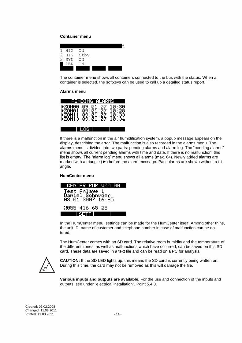
Container menu
# TYPE STATUS d 1 HIG ON 2 HIG Stby 3 SYN ON 4 PER ON STAT The container menu shows all containers connected to the bus with the status. When a container is selected, the softkeys can be used to call up a detailed status report. Alarms menu
If there is a malfunction in the air humidification system, a popup message appears on the display, describing the error. The malfunction is also recorded in the alarms menu. The alarms menu is divided into two parts: pending alarms and alarm log. The “pending alarms” menu shows all current pending alarms with time and date. If there is no malfunction, this list is empty. The “alarm log” menu shows all alarms (max. 64). Newly added alarms are marked with a triangle (►) before the alarm message. Past alarms are shown without a tri-angle. HumCenter menu
In the HumCenter menu, settings can be made for the HumCenter itself. Among other thins, the unit ID, name of customer and telephone number in case of malfunction can be en-tered. The HumCenter comes with an SD card. The relative room humidity and the temperature of the different zones, as well as malfunctions which have occurred, can be saved on this SD card. These data are saved in a text file and can be read on a PC for analysis. CAUTION: If the SD LED lights up, this means the SD card is currently being written on.
During this time, the card may not be removed as this will damage the file. Various inputs and outputs are available. For the use and connection of the inputs and
outputs, see under "electrical installation", Point 5.4.3.
Created: 07.02.2008 Changed: 11.08.2011 Printed: 11.08.2011 - 15 -
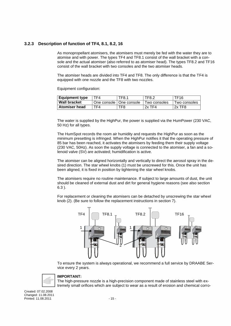
3.2.3 Description of function of TF4, 8.1, 8.2, 16
As monopropellant atomisers, the atomisers must merely be fed with the water they are to atomise and with power. The types TF4 and TF8.1 consist of the wall bracket with a con-sole and the actual atomiser (also referred to as atomiser head). The types TF8.2 and TF16 consist of the wall bracket with two consoles and the two atomiser heads. The atomiser heads are divided into TF4 and TF8. The only difference is that the TF4 is equipped with one nozzle and the TF8 with two nozzles. Equipment configuration:
Equipment type TF4 TF8.1 TF8.2 TF16 Wall bracket One console One console Two consoles Two consoles Atomiser head TF4 TF8 2x TF4 2x TF8
The water is supplied by the HighPur, the power is supplied via the HumPower (230 VAC, 50 Hz) for all types. The HumSpot records the room air humidity and requests the HighPur as soon as the minimum presetting is infringed. When the HighPur notifies it that the operating pressure of 85 bar has been reached, it activates the atomisers by feeding them their supply voltage (230 VAC, 50Hz). As soon the supply voltage is connected to the atomiser, a fan and a so-lenoid valve (SV) are activated; humidification is active. The atomiser can be aligned horizontally and vertically to direct the aerosol spray in the de-sired direction. The star wheel knobs (1) must be unscrewed for this. Once the unit has been aligned, it is fixed in position by tightening the star wheel knobs. The atomisers require no routine maintenance. If subject to large amounts of dust, the unit should be cleaned of external dust and dirt for general hygiene reasons (see also section 6.3 ).
For replacement or cleaning the atomisers can be detached by unscrewing the star wheel knob (2). (Be sure to follow the replacement instructions in section 7). TF4 TF8.1 TF8.2 TF16 1 1 2 To ensure the system is always operational, we recommend a full service by DRAABE Ser-vice every 2 years.
IMPORTANT:
The high-pressure nozzle is a high-precision component made of stainless steel with ex-tremely small orifices which are subject to wear as a result of erosion and chemical corro-

Created: 07.02.2008 Changed: 11.08.2011 Printed: 11.08.2011 - 16 -
sion. The nozzles should therefore be replaced at regular intervals (no later than every 2 years) in order to safeguard their functioning.
3.2.4 Description of function of TF32
The TF32 atomisers are fitted with eight nozzles. As a monopropellant atom-iser, the unit must merely be fed with the water it is to atomise and with power. The water is supplied by the High Pressure System (see HighPur). The power is supplied via the HumPower (230 VAC, 50 Hz).
The HumSpot records the room air humidity and requests the HighPur as soon as the minimum presetting is infringed. When the HighPur notifies it that the operating pressure of 85 bar has been reached, it activates the atomisers by feeding them their supply voltage. As soon as the supply voltage is connected to the atomiser, a fan and a solenoid valve (SV) are activated; humidification is active. A microprocessor continuously monitors the fan current. If the fan in-fringes a minimum limit (current consumption), the solenoid valve is closed and the fan is shut off. This fault is indicated by a red LED (on the underside of the TF32) flashing. If this happens please call DRAABE Service. The atomisers require no routine maintenance. High levels of dust or fluff in the environment may cause the unit to malfunction. We recommend regular checking (see section 6.3). To ensure the system is always operational, we recommend a full service by DRAABE Service every 2 years. IMPORTANT:
The high-pressure nozzle is a high-precision component made of stainless steel with extremely small orifices which are subject to wear as a result of ero-sion and chemical corrosion. The nozzles should therefore be replaced at regular intervals (no later than every 2 years) in order to safeguard their func-tioning.
Supply voltage SV Fan LED

Created: 07.02.2008 Changed: 11.08.2011 Printed: 11.08.2011 - 17 -
3.2.5 Description of NanoFog Evolution function
As a single-medium atomiser, the atomiser should only be provided with the water to be at-omised and a power supply. The NanoFog Evolution atomiser consists of the wall bracket (1) with a support and the actual atomiser (2, also known as an atomiser head). The water supply comes from the HighPur; the power is supplied via the HumPower (230 V AC, 50 Hz; 24 V DC).
The HumSpot measures the room air humidity and sends a request to the HighPur as soon as the value falls below the target. If it receives the information from the HighPur that the operating pressure of 85 bar has been reached, it uses the HumPower's power supply to trigger the atomiser. As soon as the atomiser is supplied with power, two fans and a sole-noid valve (SV) are switched on: the humidifier is working. The atomiser can be aligned horizontally or vertically to point the aerosol mister in the di-rection required. For the adjustment, the screw (1) must be loosened. After the device has been positioned, this position is fixed by tightening the screw. To align the atomiser hori-zontally, the atomiser is simply turned into the position required. The atomisers do not need regular maintenance. If there is a lot of dust, the device should be cleared of external dust and dirt (see also Chapter 6.3) from the standpoint of general hygiene.
To replace or clean the atomisers, remove the atomiser from the wall bracket (it is essential to comply with the replacement instructions in Chapter 7). 1 2 To ensure that they are always ready for use, we recommend a full service by the DRAABE customer service every two years.
NOTE:
The high-pressure nozzle is a precision component made of high-grade steel with ex-tremely small bore-holes which are subject to wear caused by erosion and chemical corro-sion. The nozzles should therefore be replaced at regular intervals (every two years at the latest) to ensure the device functions.

Created: 07.02.2008 Changed: 11.08.2011 Printed: 11.08.2011 - 18 -
3.2.6 Description of HumSpot function
The HumSpot serves to monitor the room humidity and direct the atomiser. The required room humidity is selected on the device itself. The room humidity is measured by the preci-sion hygrostats. The value is shown on the HumSpot display and compared with the target value. If it is lower than the target, it calls up the HighPur. As soon as the latter reaches its operating pressure (approx. 85 bar) and signals this to the HumSpot, it switches on the at-omiser via the HumPower. When the target value is reached, it switches the atomiser off.
H u m i d i t y & T e m p e r a t u r e
If no humidification is required for a long time (due to climatic conditions) there is a danger of bacterial growth due to stagnation. The water in the high-pressure tubes and atomisers stands still; bacteria and germs, such as fungi, can flourish. To avoid this, the HumSpot is fitted with an automatic fresh water system (AFWS). In preset cycles, it turns on the atom-iser, thus replacing the old water with new water. The HighPur is also fitted with an AFWS (see Chapter 3.2.1). CAUTION: The AFWS is an important component to ensure hygiene. Ensure that both the
power and water supply are constant. CAUTION: The maintenance/checks to be carried out regularly are an important compo-
nent to ensure hygiene. Ensure that these are carried out and recorded either by the manu-facturer or by authorised/trained staff. Various inputs and outputs are available. For the use and connection of the inputs and
outputs, see under "electrical installation", Point 5.4.3.

Created: 07.02.2008 Changed: 11.08.2011 Printed: 11.08.2011 - 19 -
HumSpot menu sequence
The menu structure is designed intuitively. Below, the display and the separate points on the menu are briefly described. Please find a detailed description of the different menu points and their parameters in the HumDigital operating instructions.
Display
H u m i d i t y & T e m p e r a t u r e
Humidity/temperature display
In normal operation, when a key is pressed the backlighting is switched on and the room humidity and temperature are displayed, as well as the status arrows on the right-hand side. The current status is shown using the status arrows on the right-hand side.
Symbol Function Description
Humidification request The precision hygrostat is requesting humidifica-tion.
AFWS request The AFWS is requesting humidification
Atomisers active The atomisers are switched on.
Bus active There is a connection to CenterPur.
Manual operation Manual operation on. This overrides the hygrostat.
6-8 Mean value Shows mean value across 15, 60 and 180 min
FOG menu
The parameters for humidification are set up in the submenus. "SETPT" submenu This menu shows the target room humidity. When this value is reached, the humidifier is switched off.

Created: 07.02.2008 Changed: 11.08.2011 Printed: 11.08.2011 - 20 -
"HYST" submenu This sets up the hysteresis. If room air humidity sinks by more than the hysteresis, the hu-midifier is switched on. "FOG" submenu In the "FOG" submenu you can choose between humidifying according to need (AUTO) and no humidification (NO). The factory setting is "AUTO". “CNT FWA” submenu In the “CNT FWA” submenu you can see the already held and finished AFWS. This counter is not resettable. DISP menu
The display settings can be changed using the submenus. "BGL ON" submenu The backlighting is switched off after a freely definable time. The time for the backlighting can be set in this menu. LCD OUT submenu After the backlighting is switched off, the LCD can continue to display the humidity and temperature, or can be switched off. UNIT T submenu The temperature unit (°C or °F) can be set in this menu. KEYLO menu
To prevent the parameters being changed accidentally, the keylock can be set. To do so, enter a freely definable four-digit lock code. CODE submenu The keylock code, anything other than 0000, can be entered in this menu If no key is pressed during the following two minutes, the keylock is set. Settings can only be made again when the correct code is entered. The pre-set code is 0000. Using this code, the keylock is not activated. LOCK submenu When this menu is selected, the code is immediately activated and the keylock set. Error messages and how to deal with them
If the HumSpot or unit is subject to an error, this is indicated on the display. The error mes-sages are listed below.
Message Description Possible causes/solution
SENS ERR The precision hygrostat is malfunctioning. Humidification has been stopped.
- Replace the sensor.
FATAL <ERROR> + error code
Hardware or software error. Humidification has been stopped.
- the HumSpot automatically tries to restart.
- If this reoccurs, replace the HumSpot.

Created: 07.02.2008 Changed: 11.08.2011 Printed: 11.08.2011 - 21 -
BUS ERR Communication with the HumCenter has been dis-rupted.
- The HumCenter is not ready for operation.
- Bus ID has been allocated twice. - Bus ID allocated but no HumCen-
ter attached.
MAX ERR Maximum hygrostat has been released.
The room humidity is above the target value set for the maximum hygrostat.
- Wiring error in maximum hygro-stat or HumPower.
- HumPower malfunction.
HPS ERR No go-ahead from DuoPur. - DuoPur is not ready for operation. - Wiring error
RANGE °C Temperature measuring range exceeded
- Temperature sensor malfunction.
3.2.7 Description of HumPower function The HumPower is the interface between the HumSpot and the atomisers. It provides the power for the HumSpot and the atomisers. When the value falls below the target, the Hum-Power receives a message from the HumSpot and connects the atomisers. When the tar-get value is reached, the atomisers are switched off. Various inputs and outputs are available. For the use and connection of the inputs and
outputs, see under "electrical installation", Point 5.4.3.
3.2.8 Description of maximum hygrostat function
The supplied maximum limiter must always be used. It is a safety element: in case of a mal-function in the precision hygrostat and/or external hygrostats, it limits the room humidity to the value selected on the regulator. The target value should be set at 10% RH above the precision hygrostats and/or external hygrostats. Upon delivery it is set at 65% RH. To change this value, remove the screw (1), set the value required and screw it back in. 1 NOTE: This safety element can prevent overhumidification and thus considerable damage.
Only authorised people may be allowed to change the target value. The operator shall be liable for ensuring that this note is complied with.
1
2
4
100
90
8070 60
50
40
30
%r.F.

Created: 07.02.2008 Changed: 11.08.2011 Printed: 11.08.2011 - 22 -
4. Planning bases The planning bases set out in the following are theoretical. In practice, the necessary hu-midification output is influenced by parameters which cannot be recorded in this documen-tation. The theoretical values must therefore in many cases be supplemented or corrected by empirical values. Our advisers will be glad to assist you with this.
4.1 Notes on planning air humidifier systems in one zone
Procedure for selecting and configuring the TF air humidifier system: - Define the room volume and the air exchange - Specify the presettings (temperature and humidity/relative humidity) - Define the humidification zones - Calculation of maximum humidification output - Definition of equipment requirement The following sections provide all the necessary information on the individual planning steps. Each planning step is accompanied by a calculation example, based on assumed
system data. The three different examples are provided to illustrate the procedure. Of course, examples cannot deal with all applications. The air humidifier system offers a broad range of solutions for custom air humidification in a wide variety of different room types. If you have any further queries or problems, the DRAABE Service team will be glad to help. Phone:+ 49 40 853277 -19
4.1.1 Example 1 (TF4, 8.1) One room to be humidified.
EXAMPLE 1
A DRAABE air humidifier system is to be installed in the paper store of a printing works to provide direct room air humidification. The following data are known: Room dimensions (L x W x H) in m: 4.0 x 30.0 x 4.0 Number of air exchange cycles per hour: 2.2 Outside air condition in winter: -15°C/90 % rel.hum. Desired room temperature: 21°C Desired relative air humidity: 53 % rel.hum. Zones: one
4.1.1.1 Calculation of maximum humidification output
The maximum humidification output is calculated by the following for-mula:
V x 1.2 x LW/h x (x2 – x1) mH2O= 1000

Created: 07.02.2008 Changed: 11.08.2011 Printed: 11.08.2011 - 23 -
mH2O: Maximum humidification output in kg/h V: Volume of air to be humidified in m³
(formula: L x W x H) AE/h: Number of air exchange cycles per hour
The number of air exchange cycles per hour depends on the usage of the room and must be determined by the system planner as part of the planning process. The following guide values can be taken as the basis: - Textiles processing: 3 -7 AE/h - Printing works: 2 -5 AE/h - Warehouses: 1 - 3 AE/h - Chilled storage: max. 1 AE/h
1.2: Fixed value for the specific weight of air in kg/m³ x2: Desired absolute humidity of the room air in g/kg x1: Minimum absolute humidity before humidification in g/kg IMPORTANT:
Where outside air represents 100 % of the air, the outside air condition in winter must be applied. If there is an air circulation system (30 % outside air, 70 % recirculated air), the resultant air mix must be applied.
For the values for x2 and x1 refer to the h,x diagram in the
Appendix (page 55). IMPORTANT:
- The formula takes no account of absorption or discharge of humidity by materials in the humidified room. In the evaporation process of the atomised water, heat is drawn from the ambient air. To maintain the desired room temperature, the room air must be heated. CAUTION: This heating is usually already provided by the heat given off by machinery.
SOLUTION TO EXAMPLE 1
For the example a required humidification output of 105 kg/h results.
If you have any queries regarding calculation of the humidification out-put please contact DRAABE Hamburg.
4.1.1.2 Definition of equipment requirement
The decisive value - the required humidification output - is now available as the primary definition basis.The following capacities of the atomisers and the HighPur are the secon-dary basis. Capacity of TF4/81. 4/8 kg/h Capacity of HighPur 200 kg/h
EXAMPLE 1 Total water flow (mH2O) = 105 kg/h

Created: 07.02.2008 Changed: 11.08.2011 Printed: 11.08.2011 - 24 -
Requirement: 1 x HumCenter 2 x HumSpot 10 x TF4 8 x TF8.1 1 x HighPur
The high-pressure tubing requirement depends on the layout. The requirement is deter-mined from the ground plan. In this example, approx. 140 metres of the DRAABE quick-assembly kit ("SMB") is required. The SMB contains the required cables, high pressure tub-
ing and fittings.
4.1.2 Example 2 (TF8.2, 16)
Planning as per sections 4.1 to 4.1.1.2.
EXAMPLE 2
A DRAABE air humidifier system is to be installed in a large printing works to provide direct room air humidification. The following data are known: Paper store (L x W x H) in m: 50.0 x 30.0 x 5.0 Number of air exchange cycles per hour: 2.2 Outside air condition in winter: -15°C/90 % rel.hum. Desired room temperature: 21°C Desired relative air humidity: 53 % rel.hum. Zones: one
10
10
20
20
20
30 40
HumSpot(1)HumSpot(2)
HighPur
TF8.1
TF4
HumCenter

Created: 07.02.2008 Changed: 11.08.2011 Printed: 11.08.2011 - 25 -
4.1.2.1 Calculation of maximum humidification output
The calculation is made as described in section 4.1.1.1.
SOLUTION TO EXAMPLE 2 For the example a required humidification output of 164 kg/h results.
4.1.2.2 Definition of equipment requirement Capacity of TF8.2/16 8/16 kg/h Capacity of HighPur 200 kg/h
EXAMPLE 2 Total water flow (mH2O) = 164 kg/h Requirement: 1 x HumCenter 2 x HumSpot 6 x TF16 8 x TF8.2 1 x HighPur
The high-pressure tubing requirement depends on the layout. The requirement is deter-mined from the ground plan. In this example, approx. 180 metres of the DRAABE quick-assembly kit ("SMB") is required. The SMB contains the required cables, high pressure tub-
ing and fittings.
10
10
20
20
30 40
TF 32
HighPur
HumSpot(1) HumSpot(2)
TF8.2
TF16
HumCenter

Created: 07.02.2008 Changed: 11.08.2011 Printed: 11.08.2011 - 26 -
4.1.3 Example 3 (TF32)
Planning as per sections 4.1 to 4.1.1.2.
EXAMPLE 3
A DRAABE air humidifier system is to be installed in the paper store of a printing works to provide direct room air humidification. The following data are known: Paper store (L x W x H) in m: 50.0 x 30.0 x 6.0 Number of air exchange cycles per hour: 2.2 Outside air condition in winter: -15°C/90 % rel.hum. Desired room temperature: 21°C Desired relative air humidity: 53 % rel.hum. Zones: one
4.1.3.1 Calculation of maximum humidification output
The calculation is made as described in section 4.1.1.1.
SOLUTION TO EXAMPLE 3 For the example a required humidification output of 177 kg/h results.
4.1.3.2 Definition of equipment requirement Capacity of TF32 32 kg/h Capacity of HighPur 200 kg/h (6xTF32 max.)
EXAMPLE 3
Total water flow (mH2O) = 195 kg/h Requirement: 1 x HumCenter 1 x HumSpot 5 x TF32 1 x HighPur
The high-pressure tubing requirement depends on the layout. The requirement is deter-mined from the ground plan. In this example, approx. 100 metres of the DRAABE quick-assembly kit ("SMB") is required. The SMB contains the required cables, high pressure tub-
ing and fittings.

Created: 07.02.2008 Changed: 11.08.2011 Printed: 11.08.2011 - 27 -
4.2 Notes on planning an air humidifier system in two zones
In this case there is only one room, but it is divided into two humidification zones. If a room has zones subject to differing heat load, or if the air exchange is not the same throughout the room, a (HumSpot) hygrostat alone cannot deliver precise measurement results. Some zones would be oversupplied, and some undersupplied. In these, or similar, cases the room can be divided into two humidification zones. Furthermore, the differing humidification out-puts of the TF4 and TF32 atomisers mean the humidification can be specifically targeted (spot humidification) or restricted.
4.2.1 Example 4 (TF16 and TF32) The humidification zones are defined on the basis of the room plan.
EXAMPLE 4 A DRAABE air humidifier system is to be installed in a printing works to provide direct room air humidification. The following data are known (index 1 for zone 1, index 2 for zone 2): Room (L x W x H) in m: 50.0 x 40.0 x 8.0 Zone 1 30.0 x 40.0 x 8.0 Zone 2 (suspended ceiling) 20.0 x 40.0 x 5.0 Number of air exchange cycles per hour: 3.01, 1.52 Outside air condition in winter: -15°C/90 % rel.hum. Desired room temperature: 21°C Desired relative air humidity: 53 % rel.hum. Zones: two
10
10
20
20
30 40
TF 32
HighPur
HumSpot(1) HumSpot(2)
TF8.2
TF16
HumCenter

Created: 07.02.2008 Changed: 11.08.2011 Printed: 11.08.2011 - 28 -
15105
5
20
10
15
20
25
30
35
40
45
50
25 30 35 40
TF 32
TF 32
TF 16
HighPur 1HighPur 2
HighPur 2
HumSpot (1)
HumSpot(2)
HumSpot(3)
HumCenter
4.2.1.1 Calculation of maximum humidification output
The calculation is made as described in section 4.1.1.1.
SOLUTION TO EXAMPLE 4 For zone 1 in the example a required humidification output of 257 kg/h results.
For zone 2 in the example a required humidification output of 54 kg/h results.
4.2.1.2 Definition of equipment requirement Capacity of TF16 16 kg/h Capacity of TF32 32 kg/h Capacity of HighPur 200 kg/h
EXAMPLE 4
Total water flow (mH2O) = 311 kg/h Requirement: 1 x Humcenter 3 x HumSpot 2 x HighPur Additionally for zone 1: 6 x TF32 2 x TF32 Additionally for zone 2: 4 x TF16
The high-pressure tubing requirement depends on the layout. The requirement is determined from the ground plan. In this example, approx. 400 metres of the DRAABE quick-assembly kit ("SMB") is required. The SMB contains the
required cables, high pressure tubing and fittings.
Zone 1
Zone 2

Created: 07.02.2008 Changed: 11.08.2011 Printed: 11.08.2011 - 29 -
4.3 Notes on water supply
As a monopropellant jet system, the DRAABE air humidifier system places special de-mands on the water it is to atomise. It may only be operated with desalinated and virtually bacteria-free pure water. Only treated water may be used. That means a three-stage treatment process must always
be run before the water can be fed in to the HighPur. All the following requirements in terms of water treatment are extremely important to en-
sure safe, hygienic functioning. The operator shall ensure that the following requirements are met on a permanent basis. The requirements for a water treatment are met if a DRAABE pure water system is used. Of course, such systems must also be subjected to regular checking and maintenance.
Glossary:
- Untreated water: This is the water as it enters the treatment stage. This water requires
treatment. Other terms for untreated water include > "drinking water" and "mains water". - Soft water: See also 4.3.2 . This is water which has been softened.
- Pure water: This is the water which is the product of the treatment
stage. Another term for pure water is > "osmosis water". CAUTION: Despite compliance with these requirements, the possibility of bac-
terial contamination of the system can never be fully excluded. Regular check-ing of the system by the operators is essential in order to prevent harm to health.
4.3.1 Untreated water requirements The operator shall ensure that the following requirements are met on a permanent basis. - The water must be free of particulates > 5µ. - The water must, as a fundamental principle, be free of colloids and organic sub-
stances. - Well water, rain water and de-ionised water are not permissible. - The water must be of drinking water quality (e.g. in terms of the number of organic
substances). - The maximum germination index must not exceed 1000 germs per ml. - It must be free of chemical substances/additives (such as chlorine, ozone, disinfec-
tant). - No ancillary equipment which modifies the properties of the untreated water must be
used (such as metering devices). - Water temperature 6-20 °C - Flow pressure 3-4 bar
4.3.2 Requirements for a water treatment system
- The water treatment must be a three-stage process. - Water softening (<0.1 °dH at outlet) - Filtering (particulate filter 5u + activated charcoal filter) - Demineralisation via reverse osmosis (inorganic membrane) - Water data at the water treatment outlet - Water hardness < 0.1 °dH - Conductance 5 -10 µS - Water temperature 6 -25 °C

Created: 07.02.2008 Changed: 11.08.2011 Printed: 11.08.2011 - 30 -
- Flow pressure 2-3 bar
- The product must be routed in a closed system until it emerges from the jet nozzle, and must have no contact with the ambient air at any point.
- Float-controlled water tanks must not be used. Instead, closed diaphragm storage tanks in stainless steel or plastic should be used for temporary storage of the prod-uct (for pressure control).
- Fittings and pipes must be made of materials approved for use in the food industry (plastic, stainless steel). Do not use copper pipe or brass!
- The pure water must be free of organic constituents.
5. Installation
5.1 Safety instructions for installation
- Installation work may be carried out only by qualified specialist personnel
(plumbers, electricians). Verification of qualifications is the responsibility of the party commissioning the installation.
- All local standards and directives governing the performance of electrical and water installations must be observed.
- The instructions set out in this section regarding placement of the system compo-nents, mounting and electrical installation procedures must be followed.
- The complete water cycle, from the drinking water supply, through the water treat-ment stage to the high-pressure system, must be executed as a closed system (in-cluding the water storage tank).
5.2 General instructions for placement
The placement of a system is defined at the planning stage and recorded in the system documentation. The following general instructions relating to placement must be followed in all cases: - Make sure the structure (wall, pillar, ceiling etc.) on which the equipment and sys-
tem components are mounted has adequate load-bearing strength and is suit-able for the mounting of such equipment and components (see section 8, “Tech-
nical Data”).
- Place the atomisers such that the aerosol mist can disperse freely. If the aerosol mist is blocked by obstacles (such as ceilings, beams etc.) swelling and eddying will occur which may result in condensation.
The following diagram presents the dimensions for the extent of the aerosol spray and the minimum clearances to be maintained. The dimensions relate to
the maximum humidification output of the atomiser nozzles and a room tempera-ture between 18° and 24°C. At higher temperatures the extent of the aerosol spray is reduced, and at lower temperatures it is increased.
- If the atomiser nozzles are mounted opposing each other, make sure there is a
minimum spacing of 8 m between them so that the aerosol sprays do not condense each other.

Created: 07.02.2008 Changed: 11.08.2011 Printed: 11.08.2011 - 31 -
- Pay attention to the flow of the room air: Do not mount atomiser nozzles in the im-mediate vicinity of an exhaust system or a cold air inlet.
- Do not direct atomiser nozzles at cold building structures such as exterior walls,
windows etc. (risk of condensation). - Cold water pipes in the vicinity of the aerosol spray must be insulated (risk of con-
densation). - The evaporation process draws heat from the ambient air. Consequently, make
sure the aerosol spray is not directed at people or directly over workstations. - To ensure optimum humidification, make sure the atomisers are distributed appro-
priately around the room.
- The system components should be installed such that sufficient space is al-lowed for maintenance access and operation.
If you have any queries relating to component placement please contact DRAABE Hamburg.
5.3 General instructions for installation
- Installation work must be carried out in accordance with generally recognised technical rules and in compliance with the connection regulations of the local utilities.
- Before beginning installation work, check that all the necessary items are pre-sent and correct as per the delivery note.
- Tubing may only be assembled by personnel of approved master craftsmen with relevant training and experience.
- No unauthorised modifications may be made to the equipment. - No additional fittings (such as valves etc.) not shown on the assembly diagram
may be fitted in the DRAABE system. - These installation instructions apply only to single systems. The manufacturers
will provide custom system diagrams for customer-specific systems. Induction sessions on the installations will also be held. The installation instructions and schematics and the induction training are binding for execution.
- Be sure to conform to the material specification.

Created: 07.02.2008 Changed: 11.08.2011 Printed: 11.08.2011 - 32 -
5.3.1 Mounting console HighPur
- If possible, the unit should be installed in a room accessible only to a limited number of people.
- The ambient temperature must be between +7°C and +35°C throughout the year.
- The installation location must be selected such that the unit cannot be exposed to direct heat or sunlight.
IMPORTANT:
The unit must be mounted on a load-bearing wall surface (minimum load ca-pacity 60 kg).
The high pressure system is supplied ready for connection with a 400 V CEE-form 16A connector. When installing the three-phase AC connection, ensure the wall socket is fitted approximately 25 cm to the left of the wall bracket on a level with the high pressure unit.
Through-holes 8 mm
Leave a top clearance of 50 cm across the full width of the mounting console. Leave a clearance of 20 cm to the right of the mounting console. Leave a clearance of 1.2 m between the bottom edge and the floor.
CAUTION:
No live parts or any other items must be mounted/placed underneath the mounting console, as damage may be caused in the event of a leak.
516 mm
185 mm
258 mm

Created: 07.02.2008 Changed: 11.08.2011 Printed: 11.08.2011 - 33 -
5.3.2 HumSpot and maximum hygrostat
- The device is to be installed in an easily accessible location at eye level.
- Select an installation location where no direct sunlight can fall on the hygrostats.
- The device and/or the hygrostat may not be installed by cold outside walls (the hu-midity regulation will be impaired).
- The hygrostat may not be influenced by heat or cold from machines, heaters, cool-ing devices, etc.
- The hygrostat must be positioned such that the air in the room can circulate around it without hindrance. (Do not place in niches, etc.)
- A space of 50 cm must be kept free around the device and the hygrostat.
HumSpot
63 mm
66
mm

Created: 07.02.2008 Changed: 11.08.2011 Printed: 11.08.2011 - 34 -
Maximum hygrostat
Through holes: 3.5 mm Cable relief
Cable feedthrough (in lid) Cable: 2 x 0.75 mm
2
Maximum length: 10m
5.3.3 HumPower
- The device can be installed in a suspended ceiling.
- The maximum distance to the HumSpot must be 30 meters.
165 m
m
239 mm
1
2
4
100
90
8070 60
50
40
30
%r.F.
98 mm
48 m
m

Created: 07.02.2008 Changed: 11.08.2011 Printed: 11.08.2011 - 35 -
5.3.4 Atomisers TF4, 8.1, 8.2, 16 Placement
- The atomisers must not be placed directly above workstations or ma-
chines.
CAUTION: There must be no impact surfaces in the path of the mist.
Otherwise condensation or precipitation may occur, resulting in drip-ping water.
- At the front the air space should be unobstructed through an angle of
90° and to a distance of 4 metres.
- Within the designated clearance area (air space at front, ceiling and floor clearance) there must be no ventilation ducts, machine parts or other articles which are sensitive to humidity.
- The stubs with the high-pressure tube DN4, routed out from the re-
duced T-piece (ring main), must not be longer than 4 metres. Ceiling Clearance (A) Floor Clearance (B) The indicated values are minimum requirements.
IMPORTANT:
The high-pressure nozzle is a high-precision component made of stainless steel with ex-tremely small orifices which are subject to wear as a result of erosion and chemical corro-sion. The nozzles should therefore be replaced at regular intervals (no later than every 2 years) in order to safeguard their functioning.
Mounting of wall bracket (with one console / two consoles) and high-pressure con-nection
To mount the wall bracket (WB) its cover (7) must first be removed. To do so, remove the lock screw (1) and the cap(s) (2) and then unscrew the star wheel knobs (3), bracing against the nut (4). The cover can then be detached towards the front.
Equipm.type A B
TF4 0.5m 2.4m TF8.1 1.0m 3.0m TF8.2 0.5m 3.0m
TF16 1.0m 4.0m
Created: 07.02.2008 Changed: 11.08.2011 Printed: 11.08.2011 - 36 -
80
68
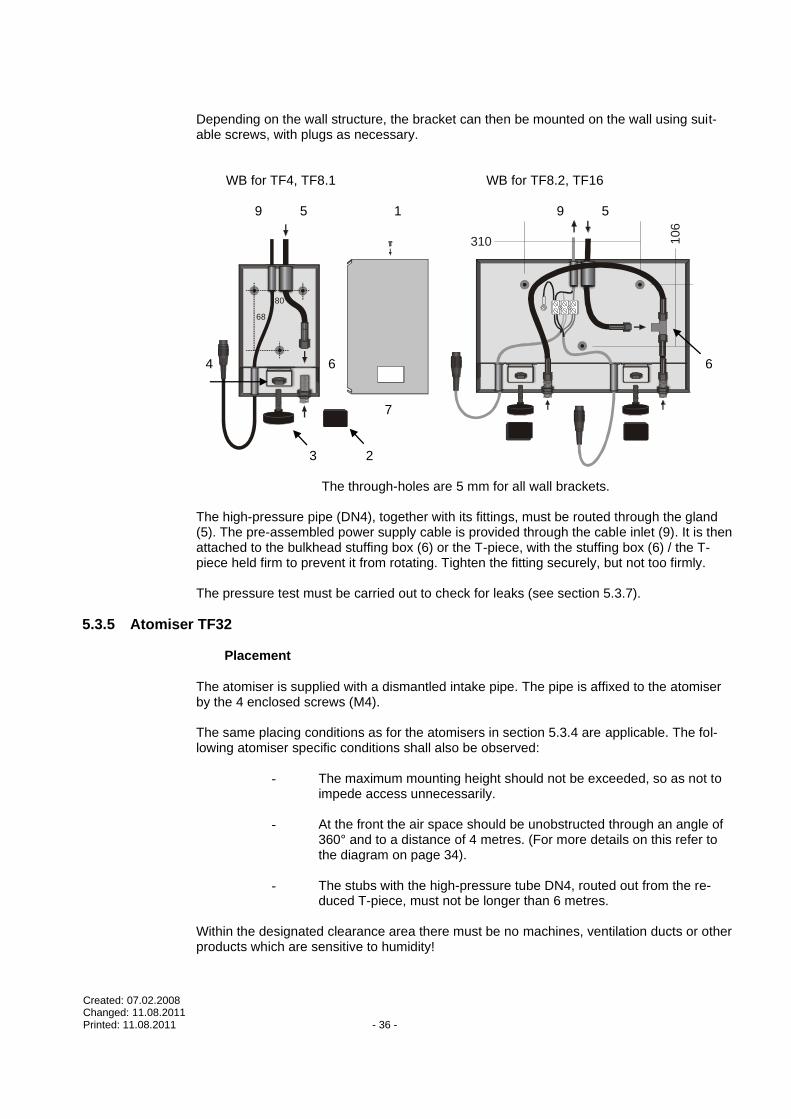
Depending on the wall structure, the bracket can then be mounted on the wall using suit-able screws, with plugs as necessary.
WB for TF4, TF8.1 WB for TF8.2, TF16
9 5 1 9 5
4 6 6 7 3 2
The through-holes are 5 mm for all wall brackets. The high-pressure pipe (DN4), together with its fittings, must be routed through the gland (5). The pre-assembled power supply cable is provided through the cable inlet (9). It is then attached to the bulkhead stuffing box (6) or the T-piece, with the stuffing box (6) / the T-piece held firm to prevent it from rotating. Tighten the fitting securely, but not too firmly. The pressure test must be carried out to check for leaks (see section 5.3.7).
5.3.5 Atomiser TF32 Placement
The atomiser is supplied with a dismantled intake pipe. The pipe is affixed to the atomiser by the 4 enclosed screws (M4). The same placing conditions as for the atomisers in section 5.3.4 are applicable. The fol-lowing atomiser specific conditions shall also be observed:
- The maximum mounting height should not be exceeded, so as not to impede access unnecessarily.
- At the front the air space should be unobstructed through an angle of
360° and to a distance of 4 metres. (For more details on this refer to the diagram on page 34).
- The stubs with the high-pressure tube DN4, routed out from the re-
duced T-piece, must not be longer than 6 metres.
Within the designated clearance area there must be no machines, ventilation ducts or other products which are sensitive to humidity!
310 106

Created: 07.02.2008 Changed: 11.08.2011 Printed: 11.08.2011 - 37 -
3 -
4 m
2 m
2 m
3 - 4 m
Intake pipe Ceiling clearance min. 1 m Floor clearance min. 4 m max. 6 m
When positioning, make sure there are no impact surfaces within the aerosol mist. A corridor between the nozzles for a pillar or such like is permitted.
Pillar Aerosol mist
Permitted corridor

Created: 07.02.2008 Changed: 11.08.2011 Printed: 11.08.2011 - 38 -
Drill hole pattern of ceiling bracket anchor points (chains):
1: Chain length approx. 1.2 m 2: Chain length approx. 1.8 m
IMPORTANT:
The high-pressure nozzle is a high-precision component made of stainless steel with extremely small orifices which are subject to wear as a result of ero-sion and chemical corrosion. The nozzles should therefore be replaced at regular intervals (no later than every 2 years) in order to safeguard their full functionality.
5.3.6 NanoFog Evolution atomiser Positioning
- The atomisers may not be placed immediately above work stations or machines.
CAUTION: No rebounding surfaces may be in the vicinity of the atomiser, or condensation
or precipitation may occur, resulting in water dropping down.
- The space in front needs to be free at an angle of 90° and a distance of 4 m.
- Within the clearance area described (space in front, ceiling and floor clearance), there may be no ventilation channels, unit parts or other parts or goods sensitive to humidity.
- The stub lines with the DN4 high-pressure tube leaving the reduced t-piece (ring mains) may not be longer than 4 m.
- The stub line and the cable are to be laid in a cable duct (45 x 30 mm) to the wall
bracket. To ensure that the atomiser can easily be replaced, make a single cut through the lid of the cable duct at a distance of 30 cm from the wall bracket.
12
00
1200
1
1
2
2
1400
14
00

Created: 07.02.2008 Changed: 11.08.2011 Printed: 11.08.2011 - 39 -
Ceiling clearance (0.40 m) Floor clearance (2.0 m)
These data relate to the wall bracket and are to be understood as minimum values. NOTE:
The high-pressure nozzle is a precision component made of high-grade steel with ex-tremely small bore-holes which are subject to wear caused by erosion and chemical corro-sion. The nozzles should therefore be replaced at regular intervals (every two years at the latest) to ensure the device functions fully.
Installing the wall bracket and high-pressure connection
Depending on the wall design, the wall bracket can be attached using appropriate screws (and dowels, as required).
30 mm
30 mm
The through holes for all wall brackets are 3.5 mm in size.

Created: 07.02.2008 Changed: 11.08.2011 Printed: 11.08.2011 - 40 -
HP-hose
Swivel nut
Pressing sleeve
Plastic washer
Incorrectpressing
Incorrectpressing
5.3.7 High-pressure tubing
After reaching 85 bar, the water is conveyed from the HighPur mounting con-sole into the high-pressure ring main (DN8). From the ring main the individual atomisers are supplied (stub, DN4). Each atomiser has a T-piece for this con-nection. - Only parts conforming to the material specification may be used. - The tubes must be laid in the protective pipe, particularly when pass-
ing through walls.
CAUTION:
When laying the tubes, make sure they do not rub on corners, wall bushings, masonry break-throughs etc. and become damaged! Make sure the high-pressure tube is able to expand and contract in response to fluctuations in pressure and temperature!
- If the tubes (whether with or without moulded-on fittings) are routed
through a hole in a wall, seal off the ends to prevent incursion of dirt. - The following minimum bend radii must be met:
DN8 tube: 115 mm DN4 tube: 40 mm
- When pressing on the fittings, be sure to conform to the specifications set out in the table. The press force and correct moulding of each fit-ting must be checked. Incorrectly moulded fittings must be replaced.
Pressing Dimensions:
Correct pressing

Created: 07.02.2008 Changed: 11.08.2011 Printed: 11.08.2011 - 41 -
Tube Internal
Diameter
in mm
Connector Diameter of
Pressing
sleeve
unpressed
in mm
Diameter of
Pressing
sleeve
pressed
(between
the fins) in
mm
Tolerance
in mm
Setting of
Measure
Gauge on
the UNIFLEX
HD160 Press
DRAABE HD3000
(quarter/year)
DN04
batchno. 12,5MPa
125bar
4 DKOL-06L-DN-4 13 11 ±0,1 2
DRAABE HD3000
(quarter/year)
DN08
batchno. 12,5MPa
125bar
7,9 DKOL-10L_DN-8 19 16 ±0,1 3

Created: 07.02.2008 Changed: 11.08.2011 Printed: 11.08.2011 - 42 -
5.3.8 Pressure testing of high-pressure tubing
- Following complete installation of the high-pressure tubing system it is essential to carry out a pressure test.
- The test device is tied to the left side fitting on the mounting console (08 l) see dia-gram below .
- Pressure is exerted against a non-return valve situated at the right-hand fitting. - The test pressure of 120 bar must be applied for 30 minutes. The test medium must be
water. The pressure must be built up in 20 bar increments. Check for leaks (in the tub-ing, fittings, wall brackets etc.) even during this build-up phase.
- If there is no leakage or pressure loss during the 30 minutes, the pressure test is
passed. In all other cases, repeat the pressure test after rectifying the problem.
IMPORTANT:
The compliance of the system with the specifications is tested by the DRAABE service engineer during commissioning. If the installation is not correct the engineer is entitled to terminate the commissioning procedure.
Mounting console HighPur Non-return valve
Test device
bar
bar
bar
Created: 07.02.2008 Changed: 11.08.2011 Printed: 11.08.2011 - 43 -
5.4 Electrical installation The documentation does not cover installation of the power supply. It does, however, set out requirements for it. Installation of the electrical components of the TF is presented, along with details of where voltage supply is required. CAUTION: The electrical installation, including the power supply, must con-
form to local safety standards and regulations. IMPORTANT NOTES on electrical installation
- Always route the connecting cables through the cable glands provided. - Fit suitable sleeves to the cable ends.
- Pay attention to the specified fuse ratings.
- Installation must be carried out by the methods set out here.
- During installation the power must be cut and secured against being unintentionally reconnected.
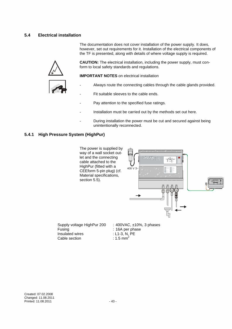
5.4.1 High Pressure System (HighPur)
The power is supplied by way of a wall socket out-let and the connecting cable attached to the HighPur (fitted with a CEEform 5-pin plug) (cf. Material specifications, section 5.5).
Supply voltage HighPur 200 : 400VAC, ±10%, 3 phases Fusing : 16A per phase Insulated wires : L1-3, N, PE Cable section : 1.5 mm
2
barbar
400 V 3~
Ein/Aus
Vordruck
Zulauf
Mindes tdruck
Betrieb
Entlastung
BioSafeLec kage
Störung
Wirk ungs überwac hte
UV-C EntkeimungElek tronisc he Sicherhei tsk ontrol le
Automatis ierte Fris chwas serfunktion
Aus beute 100%
Modem -Schni ttstel le
Anbindung Gebäudetec hnik
Xx HUM Temp Status

Created: 07.02.2008 Changed: 11.08.2011 Printed: 11.08.2011 - 44 -
5.4.2 HumCenter The HumCenter is equipped with various inputs and outputs marked with numbers and IDs.
ESC
Alarm 1 Alarm 2 100...240 VAC Main Power
L N Cont.1 Cont.2 Cont.3 Cont.4 Cont.5 Zone-BUS AUX
Gnd B A Gnd B A Gnd B A Gnd B A Gnd B A Gnd B A Gnd B A 29 28 27
2 1 8 7 6 5 4 3 23 22 21 20 19 18 17 16 15 14 13 12 11 10 9 26 25 24
!
Circuit diagram of the HighPurCEEform plug (male)3N+N+PE
16A/400VAC/50Hz
L3
L2
PE
L1
N5x1,5•
Power switch
M400 V~ 50Hz
SoftstartMotorprotector
Motorcontactor
SPS
Fuse
Fan230VAC
50Hz
Inlet pressure switch
Min. pressure switch
from motor protector
from equipment socket 3, PIN PE
Startup
Fuse
L1
24
S/S
COM 0
COM 1
COM 2
COM 3
COM 4
X0 X1 X2 X3 X4 X5 X6 X7 X10X11X12X13N0
0V
0V
Y0 Y1 Y2 Y3 Y4 Y5 Y6 Y7
PLC
MVrelief
Leakagesensor
MVinlet
toDisplay
equipment socket 3
Displayto U
V b
oa
rd
t o e
qu
ipm
en
tso
cke
t 3, P
IN1
to e
qu
ipm
en
tso
cke
t 3, P
IN2
to e
qu
ipm
en
tso
cke
t 3, P
IN3
equipment socket 4

Created: 07.02.2008 Changed: 11.08.2011 Printed: 11.08.2011 - 45 -
Connection Description
L/N (1,2) Power supply: 230 V AC, 50 Hz
Alarm 2 (3-5) Output for collective container alarm. Floating contact
Alarm 1 (6-8) Output for collective zone alarm. Floating contact
Con.1 (9-11) Container bus connection.
Con.2 (12-14) Container bus connection.
Con.3 (15-17) Container bus connection.
Con.4 (18-20) Container bus connection.
Con.5 (21-23) Container bus connection.
Zone bus (24-26) Zone bus connection.
AUX (27-29) Auxiliary bus connection for second HumCenter
5.4.2.1 HighPur to HumCenter bus connection 1. Connecting HighPur to bus
The SMB package includes a two-strand bus cable and 90-degree connector to connect the HighPur to the HumCenter. The 90-degree connector is connected to Equipment Box 4 on the HighPur. The plug is to be connected as follows:
1
2
3
4
5
Ws
Sm
Bn Pin Colour
abbrev. Colour
1 and 4 Bn Brown
2 and 3 Wh White
5 Sh Shielding
CAUTION: It is essential to ensure that this is connected as shown, as otherwise no
communication will be made. The shielding is also to be isolated with shrink-able tubing.
2. Connecting HumCenter to bus
Each container is connected to the HumCenter with the bus. It is not necessary to adhere to the order of the connection (cont. 1 – cont. 5). The HumCenter automatically recognises which type of unit is connected.
Created: 07.02.2008 Changed: 11.08.2011 Printed: 11.08.2011 - 46 -
ESC
Alarm 1 Alarm 2100...240 VAC
Main Power
L NCont.1Cont.2Cont.3Cont.4Cont.5Zone-BUSAUX
Gnd B A Gnd B A Gnd B A Gnd B A Gnd B A Gnd B A Gnd B A29 28 27
2 18 7 6 5 4 3 23 22 21 20 19 18 17 16 15 14 13 12 11 10 926 25 24
!
ESC
Alarm 1 Alarm 2100...240 VAC
Main Power
L NCont.1Cont.2Cont.3Cont.4Cont.5Zone-BUSAUX
Gnd B A Gnd B A Gnd B A Gnd B A Gnd B A Gnd B A Gnd B A29 28 27
2 18 7 6 5 4 3 23 22 21 20 19 18 17 16 15 14 13 12 11 10 926 25 24
!
ESCESC
Alarm 1 Alarm 2100...240 VAC
Main Power
L NCont.1Cont.2Cont.3Cont.4Cont.5Zone-BUSAUX
Gnd B A Gnd B A Gnd B A Gnd B A Gnd B A Gnd B A Gnd B A29 28 27
2 18 7 6 5 4 3 23 22 21 20 19 18 17 16 15 14 13 12 11 10 926 25 24
!
Connection Colour
A White
B Brown
GND Shielding
CAUTION: It is essential to ensure that this is connected as shown, as otherwise no
communication will be made. The shielding is also to be isolated with shrinkable tubing.
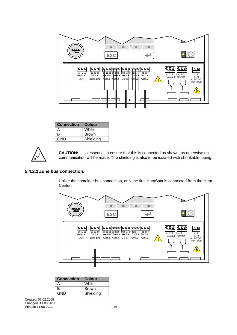
5.4.2.2 Zone bus connection.
Unlike the container bus connection, only the first HumSpot is connected from the Hum-Center.
ESC
Alarm 1 Alarm 2100...240 VAC
Main Power
L NCont.1Cont.2Cont.3Cont.4Cont.5Zone-BUSAUX
Gnd B A Gnd B A Gnd B A Gnd B A Gnd B A Gnd B A Gnd B A29 28 27
2 18 7 6 5 4 3 23 22 21 20 19 18 17 16 15 14 13 12 11 10 926 25 24
!
ESC
Alarm 1 Alarm 2100...240 VAC
Main Power
L NCont.1Cont.2Cont.3Cont.4Cont.5Zone-BUSAUX
Gnd B A Gnd B A Gnd B A Gnd B A Gnd B A Gnd B A Gnd B A29 28 27
2 18 7 6 5 4 3 23 22 21 20 19 18 17 16 15 14 13 12 11 10 926 25 24
!
ESCESC
Alarm 1 Alarm 2100...240 VAC
Main Power
L NCont.1Cont.2Cont.3Cont.4Cont.5Zone-BUSAUX
Gnd B A Gnd B A Gnd B A Gnd B A Gnd B A Gnd B A Gnd B A29 28 27
2 18 7 6 5 4 3 23 22 21 20 19 18 17 16 15 14 13 12 11 10 926 25 24
!
Connection Colour
A White
B Brown
GND Shielding

Created: 07.02.2008 Changed: 11.08.2011 Printed: 11.08.2011 - 47 -
CAUTION: It is essential to ensure that this is connected as shown, as otherwise no
communication will be made. The shielding is also to be isolated with shrinkable tubing.
5.4.2.3 Zone and container collective alarm The two outputs provide several options for use. Two separate contacts are available. The alarm outputs can be used both as NO and N/C contacts.
ESC
Alarm 1 Alarm 2100...240 VAC
Main Power
L NCont.1Cont.2Cont.3Cont.4Cont.5Zone-BUSAUX !
ESC
Alarm 1 Alarm 2100...240 VAC
Main Power
L NCont.1Cont.2Cont.3Cont.4Cont.5Zone-BUSAUX !
ESCESC
Alarm 1 Alarm 2100...240 VAC
Main Power
L NCont.1Cont.2Cont.3Cont.4Cont.5Zone-BUSAUX !
Speisung
24... 240 VAC/DCImax. 2 A
Speisung
24... 240 VAC/DCImax. 2 A
Speisung
24... 240 VAC/DCImax. 2 A
Zonen Anlagen

Created: 07.02.2008 Changed: 11.08.2011 Printed: 11.08.2011 - 48 -
5.4.2.4 BMS connection
The HumCenter has an interface to link to the building services management system. The HumCenter is designed so that the parameters to be transferred are converted to the bus system using an external converter (e.g. RS232 Ethernet converter). The converter is attached at the RS232 interface on the top of the HumCenter next to the SD card slot. The maximum cable length between the HumCenter and the converter is 3m. It is up to the operator to provide the converter.
Parameters
The following parameters are transferred: - Date/time - Zone alarms - Container alarms - Current zone values (humidity, temperature)
Each parameter is labelled in the telegram using identifiers:
Identifier Parameter Format Notes
A Date/time U8;U8;U16;U8;U8;U8 (DD;MM;YYYY;HH;MM;SS) Example: A07;11;2007;11;45;15
Time telegram sent
B Zone alarms U32 Bit0=Zone1, Bit1=Zone2 etc. Examples: B0 = no alarm B1 = zone 1 alarm B3 = zone 1 and zone 2 alarm
C Container alarms
U8 Bit0=Container1 etc. Examples: C0 = no alarm C1 = container 1 alarm
D Current zone values
Float, Float (HH.H;TT.T) Example: D1:39.5;23.8
HH.H in [%RH] TT.T in [°C]
Z CRC U16
The parameters transferred can only be read; it is not possible to change the settings via the BMS.

Created: 07.02.2008 Changed: 11.08.2011 Printed: 11.08.2011 - 49 -
Telegram
Every five seconds, the HumCenter sends a telegram with the parameters described above. The following is an explanation of the symbols used in the telegram and the tele-gram layout, using an example. The following symbols are used in the telegram:
Symbol Description Notes
* Start symbol Start of telegram A - Z Identifier Identifies the parameter : Index Index in case of array data (D:1) ; Data separator Separates the data (D:1; 25.0; 50.0 - ";" sepa-
rates the data from the index and the tempera-ture from the humidity)
. Decimal point CR+LF End of line Lines of telegram finish with a "carriage return"
and "line feed".
Layout of a sample telegram with the following configuration: - 3 zones (HumSpots) - 2 containers Telegram: *A07;11;2007;11;29;04;B0C2D:1;43.3;24.8;D:2;42.5;23.3;D3:40.8;20.1Z32219 The telegram contains the following information: - Date/time: 07.11.2007, 11:29:04 (A07;11;2007;11;29;04)
- Zone alarms: No alarm (B0)
- Container alarms: Container 2 alarm (C2)
- Zone 1 values: Humidity: 43.3 % rH, temp.: 24.8 °C (D:1;43.3;24.8)
- Zone 2 values: Humidity: 42.5 % rH, temp.: 23.3 °C (D:1;42.5;23.3)
- Zone 3 values: Humidity: 40.8 % rH, temp.: 20.1 °C (D:1;40.8;20.1)
- Checksum: 32219 (Z32219)
Transfer parameters
19,200 bit/s
Data bits: 8
Stop bit: 1
Parity: none

Created: 07.02.2008 Changed: 11.08.2011 Printed: 11.08.2011 - 50 -
Flow control: none
CRC checksum
It is not usually necessary to calculate and evaluate the checksum. If desired, it can be calculated as follows: Up to and including the "Z" identifier, the function "crc_one_byte()" is accessed for every figure in the telegram, with "*oldchecksum" initialised to 0 at the start of the telegram. Algorithm
/* calculate 16-Bit CRC */ /* At start of calculation *oldchecksumP must be */ /* initialised to 0 */ /* oldchecksumP (IO): pointer on (previous) checksum*/ /* b: next byte of data stream */ void crc_one_byte(u16 *oldchecksumP, unsigned char b) { u16 result; unsigned char a=b ^ (*oldchecksumP)>>8 ^ (*oldchecksumP)>>4 ^ (*oldchecksumP)>>1 ^ (*oldchecksumP)<<1; result = (*oldchecksumP)<<8 | a ^ a>>7; *oldchecksumP = result; }
5.4.3 HumSpot
There are various possible connection methods available.
Connection Description
Power (1-3) Power supply and atomiser release
ExtHRequ (4-5) External hygrostat/BMS connection
HighPur (6-9) Request/release for HighPur (not required if Hum-Center not connected).
Bus IN (10-12) Zone bus connection (from HumCenter or previous HumSpot)
Bus OUT (13-15) Zone bus connection (to next HumSpot)

Created: 07.02.2008 Changed: 11.08.2011 Printed: 11.08.2011 - 51 -
67
89
12345
15
14
13
12
11
10
5.4.3.1 Connections between HumSpots
The HumSpot has electrical control of only the group of atomisers in question. These are powered by the HumPower during atomisation. As regards water hydraulics, several groups can be powered by one HighPur. This is limited by the HighPur’s capacity.
The separate groups must be able to send requests to the HighPur independently of one another and the HighPur must be able to inform the group in question that it has reached operating pressure. To this end, a parallel connection is made between the “HighPur re-quest” and “Operating pressure reached” or “Bus IN” and “Bus OUT” clamps from one de-
vice to the next. When making this connection, ensure the colours and/or cable numbers are strictly kept in the proper order as it may otherwise lead to malfunctions.

Created: 07.02.2008 Changed: 11.08.2011 Printed: 11.08.2011 - 52 -
Bus connection The bus line from the HumCenter is fitted to the first HumSpot at BUS IN. From Bus OUT, the bus line goes to the Bus IN of the next HumSpot.
67
89
12345
15
141
312
1110
67
89
12345
15
141
312
1110
A
B
The supply (24 V DC) is connected using cable A. The ends of the cables must be fitted
with wire end ferrules.
Connection Colour
1: V+ Brown
2: FogOn White
3: GND Green
Cable type: LIYY 3 x 0.75 mm2 (colour or number code)
Ensure wiring is exactly parallel for bus line B. The ends of the cables must be fitted with
wire end ferrules. If Bus OUT is required, remove the resistance.
Connection Colour
A White
B Brown
GND Shielding
Cable type: LIYY 2 x 0.25 mm
2 (colour or number code)
CAUTION: It is essential to ensure that this is connected as shown, as otherwise no
communication will be made. The shielding is also to be isolated with shrinkable tubing. CAUTION: Only remove the resistance if Bus OUT is required. There must be resistance at
the last HumSpot or communication will be disrupted.

Created: 07.02.2008 Changed: 11.08.2011 Printed: 11.08.2011 - 53 -
Analogue connection In the case of extensions to the unit using the group control device UNILOG 3000, the HumSpots are to be connected to one another using the 4-pole control cable (Cable B). In this case, the bus cable is not to be fitted.
67
89
12345
1514
1312
1110
A
BUnilog 3000
OK OK
J1
%
B
1234
The supply (24 V DC) is connected using cable A. The ends of the cables must be fitted
with wire end ferrules.
Cable type: LIYY 3 x 0.75 mm2 (colour or number code)
Connection Colour
1: V+ Brown
2: FogOn White
3: GND Green
Ensure wiring is exactly parallel for signal line B. The ends of the cables must be fitted with
wire end ferrules. Cable type: LIYY 4 x 0.75 mm
2 (colour or number code)
Connection UNILOG
Colour
4 Brown
3 Green
2 Yellow
1 White
Connection HumSpot
Colour
9: HPrequest Brown
8: SPS 24 Green
7: V+ Yellow
6: HPS Ready White

Created: 07.02.2008 Changed: 11.08.2011 Printed: 11.08.2011 - 54 -
5.4.3.2 Connecting an external hygrostat/BMS
The HumSpot precision hygrostat measures the immediate room humidity and tempera-ture. For some applications, this does not suffice. In this case, an external hygrostat can
be fitted to the device. To do so, the precision hygrostat and the regulator are disabled: the device is controlled by the external hygrostat.
External hygrostat requirements: The device must be equipped with a target value regu-
lator. When the target value is reached, a 24 V DC contact must open up. Further parame-ters, such as the implementation (IP protection, etc) depend upon the project. The external hygrostat should not be further than 50 metres from the HumSpot. In some cases, the air humidifier is not intended to be controlled by its own precision hy-grostat, but by a building services management system (BMS) used by the operator. In
this case, the precision hygrostat and the regulator are also disabled. BMS requirements The BMS needs only provide a 24 V DC contact which closes when
the humidifier is required. Depending on the connection design, the distance between the HumSpot and the BMS plays a role in safe operation. Do not allow the distance to exceed 300 metres.
67
89
12345
15
14
13
12
11
10
Connection
4: Ext- GND
5: Ext+ 24VDC
The following specifications apply for both applications: Cable type: LIYY 2 x 0.75 mm
2
Input: ExtHRequ (4-5).

Created: 07.02.2008 Changed: 11.08.2011 Printed: 11.08.2011 - 55 -
5.4.3.3 Connecting the HumPower There are various possible connection methods available.
Connection Description
Power IN (3-5) Power supply connection (100-240V AC, 50-60Hz)
Power OUT (1-2) Power supply output The power can be connected to the IN valve (atomiser power supply) using a cable link.
Valve IN (6-8) Connection for atomiser power supply. The Power OUT can be connected using cable links.
Valve OUT (9-11) Connection for atomiser
Fan Out (12-13) 24 V DC connection for NanoFog fans.
Max. hygrostat value (18-19)
Connection for external maximum hygrostat.
HumSpot (20-22) HumSpot connection.
DC
AC
100..240V AC50 / 60 Hz
Hand
override
1415
FAN Out24V DC
1213
Max.Wert
HygroStat
1819
Max.WertHygroStat
Im Raum
installiert! !
Hum Power
Hum SpotSpeisung & FogON
2122 20
GNDGND 24V24VFogON Fog Fog HAND
Hum Spot
Zonen-steuerung
oder extern
48 ...240 V AC/DCSpeisung !
DC
AC
100..240V AC50 / 60 Hz
Hand
overrideFAN Out24V DC
Max.Wert
HygroStat
1819
Max.WertHygroStat
Im Raum
installiert! !
Hum Power
Hum SpotSpeisung & FogON
2122 20
GNDGND 24V24VFogON Fog Fog HAND
DC
AC
100..240V AC50 / 60 Hz
T 1
,6 A
T 1
,6 A
N LPE
Power
OUT
5432178910
11
LL NN PE
T 6
,3 A
T 6
,3 A
Valve OUT Valve INPower
IN
T 1
,6 A
T 1
,6 A
PE
Power
OUT
5432178910
11
LL NN PE
T 6
,3 A
T 6
,3 A
Valve OUT Valve INPower
IN
T 1
,6 A
T 1
,6 A
PE
Power
OUT
5432178910
11
LL NN PE
T 6
,3 A
T 6
,3 A
Valve OUT Valve INPower
IN
Hand
overrideFAN Out24V DC
Max.Wert
HygroStat
1819
Max.WertHygroStat
Im Raum
installiert! !
Hum Power
Hum SpotSpeisung & FogON
2122 20
GNDGND 24V24VFogON Fog Fog HAND
Hum Spot
Zonen-steuerung
oder extern
48 ...240 V AC/DCSpeisung !
Nur NanoFog!
N L
5.4.3.4 Connection for external maximum hygrostat
NOTES on electrical installation:
- Lay the connection cable through the feed-throughs for this purpose. - Fix the cables in place with the cable relief provided. - The ends of the cables must be fitted with suitable wire end ferrules. - The installation may only be carried out in accordance with the plans discussed
here. - During the installation, the power supply must be switched off and prevented from
accidentally being switched on again.

Created: 07.02.2008 Changed: 11.08.2011 Printed: 11.08.2011 - 56 -
Cable relief
Cable feedthrough (in lid) Cable: 2 x 0.75 mm
2
Maximum length: 10m The cable must be connected as shown. From there, it leads to the HumPower input. There, it is laid through the cable feedthrough and connected at the maximum value hygrostat input (clamps 18 and 19).
5.4.5 Atomisers TF4, 8.1, 8.2, 16 The power is supplied by the HumPower. If atomising is required, it switches the 230 VAC, 50 Hz through to all connected atomisers. Supply voltage: 230VAC, 50 Hz, 1-phase, neutral and protective earth conductor (identical for all types) Fusing: in the HumPower CAUTION: Before and while working on the unit, make sure no cables are live and the
power supply is secured against being unintentionally switched back on. The wall brackets (WH) are supplied with a ready made-up 3 metre power cable. Only this cable may be used to connect up the atomiser. It comprises the plug for the atomiser (1), the cable (see material specification) and a junction box. It must be ensured that the PE conductor (colour: green/yellow) is connected. Fit sleeves to all cable ends. WH for TF4, TF8.1 WH for TF8.2, TF16
3x0.75mm2 3x0.75mm
2 3x0.75mm
2 3x0.75mm
2
from to from to HumPower next HumPower next atomiser atomiser Plug Plug (1) to (1) to atomiser Atomiser
Plug (1) to atomiser
1
2
4
100
90
8070 60
50
40
30
%r.F.
98 mm
48 m
m

Created: 07.02.2008 Changed: 11.08.2011 Printed: 11.08.2011 - 57 -
Circuit diagram, atomizer TF 32
PE
2
3
13 x 1,5•
Fan230VAC
50Hz
PE
2
3
1
Equipment plug(male)
Equipment socket(female)
Electronic
Red LED
MV
5.4.6 Atomiser TF32
The power is supplied by the HumPower. If atomising is required, it switches the 230 VAC, 50 Hz through to all connected atomisers. Supply voltage: 230VAC, 50 Hz, 1-phase, neutral and
Protective earth conductor Fusing: in the HumPower CAUTION: Before and while working on the unit, make sure no cables are live
and the power supply is secured against being unintentionally switched back on. The quick-assembly kit ("SMB") includes a 4-way female junction box connec-tor for the atomiser. Only it may be used to connect up the unit. It must be ensured that the PE conductor (colour: green/yellow) is connected. Fit sleeves to all cable ends.
Equipment socket connections:
PIN 1 Phase
PIN 2 Neutral PIN 3 Vacant PIN PE PE conductor (colour: green/yellow)

Created: 07.02.2008 Changed: 11.08.2011 Printed: 11.08.2011 - 58 -
5.4.7 NanoFog Evolution atomiser This is powered by the HumPower. During atomisation, this switches through the 230V AC, 50 Hz and 24 V AC to all atomisers attached. Power supply: 230V AC, 50 Hz, 1 phase, neutral and protective earth conductor 24VDC Fuse protection: in the HumPower CAUTION: Before and during work on the device, ensure that all lines are inactive and the
power supply is protected against accidentally being switched on. The wall brackets (WBs) are delivered with a pre-assembled 4-m long supply cable. This, and only this, may be used to connect the atomisers. It includes the plug for the atomiser (1), the cable (see material specifications) and a distribution box. It is essential to ensure that the protective earth conductors (colour: green/yellow) are con-nected. All cable ends must be fitted with wire end ferrules. The connections must be made as follows:
Strand Description
1 Phase L1
2 0V DC
3 Neutral conductor N
4 24VDC
green/yellow Protective earth conductor

Created: 07.02.2008 Changed: 11.08.2011 Printed: 11.08.2011 - 59 -
NanoFog Evolution
5x0.75mm2
5x0.75mm
2 to next
from HumPower atomiser
Plug (1) to atomiser
Created: 07.02.2008 Changed: 11.08.2011 Printed: 11.08.2011 - 60 -
5.5 Material specifications
5.5.1 High pressure High-pressure tube
DN8
DRAABE HD 2000 R 1 01* DN 8 125 *(1 01 = production batch) DN 4
Type 2010N-025V00
High-pressure fittings
Press fitting with O-ring to DIN 2353 – V4A
Materials: NBR > O-ring 1.4571 > all metals
Type 1: DKOL 10L-DN-8 Type 2: DKOL 06L-DN-4 Reduced T-piece
Material: 1.4571 EXMAR Type: XTVR-10-06-10-L Straight coupling Material: 1.4571 EXMAR Type: XGV-10L

Created: 07.02.2008 Changed: 11.08.2011 Printed: 11.08.2011 - 61 -
5.5.2 Electrical components
Electrical cable
Usage: From house mains to HumPower. Designation: H05VV-F 3 x 0.75 mm² (PE conductor green/yellow) Performance: Operator Usage: From house mains to HumPower. Designation: H05VV-F 2 x 0.75 mm² Performance: Operator Usage: From HumPower to HumSpot (cable A)
Designation: LIYY 3x0.75mm2 (colour or number coded)
Performance: Provided by DRAABE SMB Usage: From HighPur to HumCenter and from HumCenter to HumSpot (cable B).
Designation: LIYCY 2x0.25mm2 (colour or number coded)
Performance: Provided by DRAABE SMB Usage: From HumPower to TF4, 8.1, 8.2, 16, 32 atomiser (cable C)
Designation: H05VV-F 3 x 0.75 mm² (PE conductor green/yellow) Performance: Provided by DRAABE SMB Usage: From HumPower to NanoFog atomiser (cable C)
Designation: JZ-600 5x 0.5 mm2 (PE conductor green/yellow)
Performance: Provided by DRAABE SMB
Power socket (wall mounted)
Usage: High Pressure System, HighPur Tech. data: 400VAC, 16A, Switching capacity min. 2KW,
splash-proof, CEEform, L1, L2, L3, N, PE

Created: 07.02.2008 Changed: 11.08.2011 Printed: 11.08.2011 - 62 -
6. Operation The system may only be operated by the operating company, or personnel authorised by the said operating company, when the installation has been ac-ceptance tested by DRAABE Service or by personnel authorised by DRAABE. The operators must also have undergone induction by DRAABE. Following commissioning and induction, it is the duty of the operating company to ensure that only persons having undergone such induction are allowed to operate the system. This provision forms part of the DRAABE warranty conditions.
6.1 Shutdown in daily operation It may be necessary to shut down the system for maintenance purposes, to replace faulty components or remove them for servicing, or in the event of faults in the system. The question of when a shutdown is required is dealt with in more detail in section 7 (refer also to the replacement instructions for the
individual units). CAUTION: When the system is shut down, it must always be ensured that un-
intentional restarting (water and power supply, depending on shutdown mode) is prevented. Staff should be notified of the situation. Complete shutdown. This means the power is cut to system components, or
even the entire system, and the water supply is shut off. HighPur: Power switch off (position "0").
If a wall socket with switch is installed, switch that switch off also (position "0“). If there is no switch, pull the power plug. Shut off the water infeed.
HumSpot: Set presetter to 20% rel.hum. Atomisers: Pull power plug. As necessary, detach high-pressure supply
line (CAUTION: Ensure HighPur is secured against starting).
CAUTION: If the shutdown is prolonged (longer than 24 hours) there is a
risk of bacterial contamination caused by standstill (automatic fresh water sys-tem inactive) . Please be sure to notify DRAABE Service before undertaking a complete shutdown. Partial shutdown. This involves merely preventing a system startup when
components need to be replaced.
HighPur: Pull the 7-pin plug (equipment socket 3 see page 38) under the HighPur. The HighPur and the atomisers can no longer start up. Shut off the water supply (only if the HighPur is being replaced).
HumSpot: Set presetter to 20% rel.hum. > The HighPur and the atomis-
ers can then only atomise by way of the automatic fresh water system (every 12 hours for 6 minutes).
Atomisers: Pull power plug. As necessary, detach high-pressure supply
line (CAUTION: Ensure HighPur is secured against starting).
CAUTION: If the shutdown is prolonged (longer than 24 hours) there is a
risk of bacterial contamination caused by standstill (automatic fresh water sys-
Created: 07.02.2008 Changed: 11.08.2011 Printed: 11.08.2011 - 63 -
tem inactive) . Please be sure to notify DRAABE Service before undertaking a complete shutdown.
6.2 Startup in daily operation Depending on whether the shutdown is partial or complete, the restart must be executed in reverse order (also refer to the replacement instructions for the
individual units). Basic rules: HighPur First connect the water supply, then the 400VAC supply, then
switch on at the power switch (position "I“).
HumSpot Reset presetting selector to desired value. Atomisers: First reconnect the high-pressure supply, then the power plug.
6.3 Checks If irregularities or malfunctions are detected in the course of checking, notify DRAABE Service immediately! Checks may be carried out only by trained per-sonnel who have undergone the necessary induction. Verification of the suit-ability and qualification of personnel is incumbent upon the operating com-pany. HighPur Operating pressure: Check the operating pressure on the
manometer. It should be between 85 and 95 bar. If the High-Pur is not running, the presetting on the selector of the HumSpot may be increased until the system starts up (CAUTION: do not forget to reset).
Cycle: every 2 weeks
Atomiser Check aerosol mist / result of atomising. Occasionally check
that all the nozzles are atomising and a uniform aerosol mist is being produced.
Cycle: every 2 weeks
CAUTION: This check is important because early detection of a very poor at-
omising result will prevent damage. The poorer the atomising result, the larger the drip. Drips can lead to damage by corrosion.
The fans may get blocked in areas with high formation of dust and dirt and thus impair the function of the atomiser. This must be checked and any con-tamination is to be eliminated.
CAUTION: Do not clean with water or any type of cleaning agent, only vac-uum clean. Before cleaning, the device must be cut from the power supply
and secured against unintentional restart.
Cycle: every 4 weeks
Created: 07.02.2008 Changed: 11.08.2011 Printed: 11.08.2011 - 64 -
Maximum hygrostat The switching point of the hygrostat can be checked with a moisture meter.
When you move the presetting selector around the switching point, a clicking is audible. Permissible deviations depend on the type used (also see Techni-cal data, section 8).
Cycle: once a month
CAUTION: The moisture meter must be calibrated. DRAABE Service will be
glad to help you select a suitable meter. The measurement may only be per-formed by trained personnel. This check is very important, because malfunc-tions in the hygrostat can lead to excessive humidification and thus to damage.
In areas with high formation of dust or dirt, an impaired sensor element or a blocked protective grid can highly disturb the function of the air humidifier sys-tem. This must be checked and any contamination is to be eliminated.
CAUTION: Do not clean with water or any type of cleaning agent, only vac-uum clean.
Cycle: once a month
7. Replacing components
Please notify DRAABE Service if you find a fault in the system. DRAABE Industrietechnik GmbH Schnackenburgallee 18 D-22525 Hamburg Tel.: +49 40 85 32 77 19 Hours of business (Mo. to Fr.)
8 a.m. – 5 p.m. Tel.: +49 177 85 32 777 Emergency service (Mo. to Fr.)
6 a.m. – 8 a.m. / 5 p.m. – 8 p.m. Components may only be replaced by trained personnel who have undergone the neces-sary induction. Verification of the suitability, qualification and training of personnel is incum-bent upon the operating company. The operating company is obliged to conform to DRAABE instructions, in particular the instructions contained in this documentation. CAUTION:
- Inform the personnel in the vicinity that work is being carried out on the air humidifier system.
- Make sure the system cannot be unintentionally restarted.

Created: 07.02.2008 Changed: 11.08.2011 Printed: 11.08.2011 - 65 -
7.1 High Pressure System (HighPur)
- Unplug the connector (1) from the unit by slackening the knurled ring on the connector. - Operating pressure must be 0; read off from manometer (2). If the HighPur was opera-
tional, wait for the pressure to drop. - Switch off at main switch (3) and unplug connector (4). - Shut off water supply to HighPur and relieve inlet pressure (0 bar). - Detach the self-retracting tubes (5) (using an open-ended spanner size 14/17) and al-
low them to retract into the container. - Remove HighPur from mounting console and mount new unit. - Reconnect in reverse order of removal.
4 1 3
5 2
IMPORTANT: The HighPur may indicate a supply pressure fault (red "Supply
pressure" LED lit). Check that the upstream water treatment system is deliver-ing a pressure between 2 – 3 bar and make sure the presetting is below the preset lower limit over the hygrostat. CAUTION: When removing and re-attaching the tubes make sure they are
kept straight.
CAUTION: When the system has restarted check for leaks. Check the system
from time to time over the next two days.

Created: 07.02.2008 Changed: 11.08.2011 Printed: 11.08.2011 - 66 -
7.2 Atomisers TF 4, 8.1, 8.2, 16
- Remove junction box (1) from the atomiser. CAUTION 230 VAC!
- Remove high-pressure line, quick coupling (2) from atomiser. Collect any water residue in a bucket.
- Remove atomiser by loosening the star wheel knob (3). - Install new atomiser in reverse order of removal.
TF4, 8.1 TF8.2, 16 (figure TF4) (figure TF16)
1 3 2

Created: 07.02.2008 Changed: 11.08.2011 Printed: 11.08.2011 - 67 -
7.3 Atomiser TF 32
- Unplug the 7-pin connector from the HighPur. - Operating pressure must be 0 bar; read off from manometers on mounting console. If
the HighPur was operational, wait for the pressure to drop. - Switch off HighPur at power switch. - Remove junction box (1) from TF32 by slackening the knurled ring on the box.
CAUTION: 230 VAC!
- Remove high-pressure line (2) from TF32 (open-ended spanner size 14). Collect any water residue in a bucket.
- Release atomiser from spring snap. Detach intake pipe (4 x M4 screws). - Screw the intake pipe (3) onto the new atomiser, attach the unit and connect up in re-
verse order of disconnection. - Switch HighPur back on and reconnect 7-pin connector to HighPur.
1 3 2
IMPORTANT: When operating the replacement unit the first time note that drip-
free shut-off of the atomiser is attained only after repeatedly switching on and off (by the presetter of the Unilog 3000). Protect/cover equipment and goods accord-ingly. This is due to air in the high-pressure system of the replacement unit. Once the unit has stopped without dripping, it will do so permanently from then on. CAUTION: When the system has restarted check for leaks. Check the system from
time to time over the next two days.
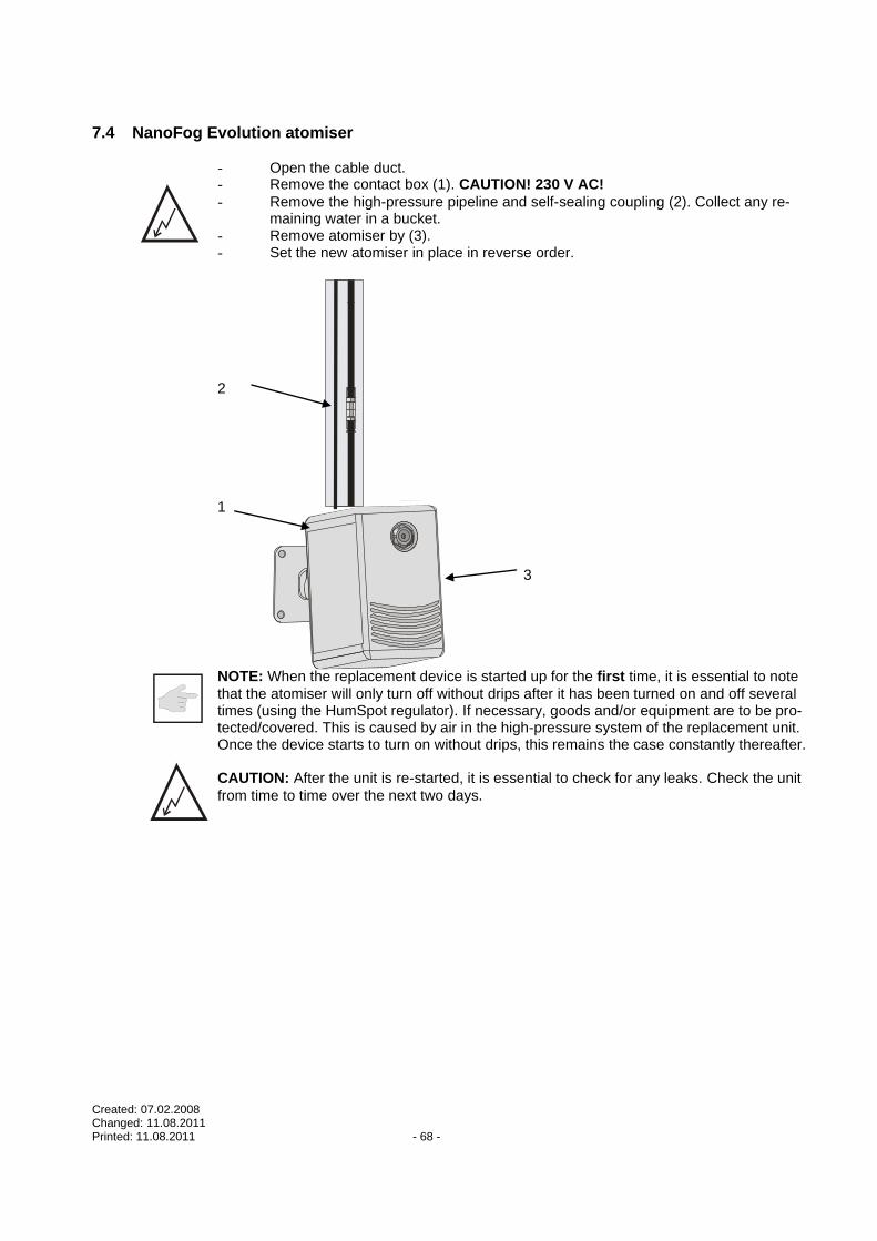
Created: 07.02.2008 Changed: 11.08.2011 Printed: 11.08.2011 - 68 -
7.4 NanoFog Evolution atomiser
- Open the cable duct. - Remove the contact box (1). CAUTION! 230 V AC!
- Remove the high-pressure pipeline and self-sealing coupling (2). Collect any re-maining water in a bucket.
- Remove atomiser by (3). - Set the new atomiser in place in reverse order.
2
1
3 NOTE: When the replacement device is started up for the first time, it is essential to note
that the atomiser will only turn off without drips after it has been turned on and off several times (using the HumSpot regulator). If necessary, goods and/or equipment are to be pro-tected/covered. This is caused by air in the high-pressure system of the replacement unit. Once the device starts to turn on without drips, this remains the case constantly thereafter. CAUTION: After the unit is re-started, it is essential to check for any leaks. Check the unit
from time to time over the next two days.
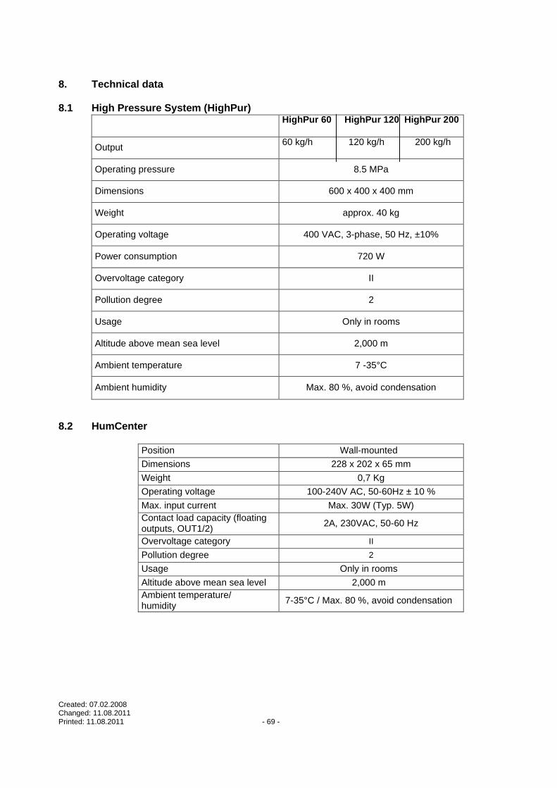
Created: 07.02.2008 Changed: 11.08.2011 Printed: 11.08.2011 - 69 -
8. Technical data 8.1 High Pressure System (HighPur)
HighPur 60 HighPur 120 HighPur 200
Output 60 kg/h 120 kg/h 200 kg/h
Operating pressure 8.5 MPa
Dimensions 600 x 400 x 400 mm
Weight approx. 40 kg
Operating voltage 400 VAC, 3-phase, 50 Hz, ±10%
Power consumption 720 W
Overvoltage category II
Pollution degree 2
Usage Only in rooms
Altitude above mean sea level 2,000 m
Ambient temperature 7 -35°C
Ambient humidity Max. 80 %, avoid condensation
8.2 HumCenter
Position Wall-mounted
Dimensions 228 x 202 x 65 mm
Weight 0,7 Kg
Operating voltage 100-240V AC, 50-60Hz ± 10 %
Max. input current Max. 30W (Typ. 5W)
Contact load capacity (floating outputs, OUT1/2)
2A, 230VAC, 50-60 Hz
Overvoltage category II
Pollution degree 2
Usage Only in rooms
Altitude above mean sea level 2,000 m
Ambient temperature/ humidity
7-35°C / Max. 80 %, avoid condensation

Created: 07.02.2008 Changed: 11.08.2011 Printed: 11.08.2011 - 70 -
8.3 Atomisers TF4, TF8.1, TF 8.2, TF16, TF32
TF4 TF8.1 TF8.2 TF16 TF32
Output (kg/h*) 4 8 8 16 32
Operating pressure Ca. 85.0MPa
Drip size (Sauter) < 15 µ
Dimensions 120 x 370 x 300 400 x 370 x 300 600 x 600 x 250
Weight (Kg) 2,8 3,3 7,5 8,4 9,0
Operating voltage 230VAC, 50-60Hz, ± 10%
Power consumption 12 24 88
Overvoltage Category II
Pollution Degree 2
Usage Only in rooms
Altitude above mean sea level
2000m
Ambient temperature 7 – 35°C
Ambient humidity Max. 95%, avoid condensation
* : Depending on jet nozzle used
8.4 Atomiser NanoFog Evolution
Output (kg/h*) 3
Operating pressure Ca. 85,0MPa
Drip size (Sauter) < 15 µ
Dimensions 60 x 100 x 150 mm
Weight (Kg) 1,58
Operating voltage 230VAC, 50-60Hz, ± 10% 24VDC
Power consumption 8,0W
Overvoltage Category II
Pollution Degree 2
Usage Only in rooms
Altitude above mean sea level
2000m
Ambient temperature 7 – 35°C
Ambient humidity Max. 95%, avoid condensation
* : Depending on jet nozzle used
8.5 HumSpot
Measuring element (hygrostat) Capacitive
Control range 10-90% relative humidity (rel.hum.)
Position Wall-mounted
Dimensions 185 x 110 x 55 mm
Weight 0,7 kg
Operating voltage 24V DC, ± 20%
Power consumption 1W (without backlight) 1,5W (with backlight)
Overvoltage category II
Pollution degree 2
Usage Only in rooms
Altitude above mean sea level 2000 m
Ambient temperature 7-35°C
Ambient humidity Max. 95%, avoid condensation

Created: 07.02.2008 Changed: 11.08.2011 Printed: 11.08.2011 - 71 -
8.6 HumPower
Position Wall-mounted
Dimensions 250 x 180 x 65 mm
Weight 2,5 Kg
Operating voltage 100-240V AC, 50-60Hz ± 10 %
Max. input current Max. 30W
Contact load capacity 8A, 230VAC, 50-60 Hz
Overvoltage category II
Pollution degree 2
Usage Only in rooms
Altitude above mean sea level 2,000 m
Ambient temperature/ humidity
7-35°C / Max. 80 %, avoid condensation
8.7 Maximum hygrostat
Measuring element Plastic
Presetting selector In device
Control range 30-100% relative humidity (rel.hum.)
Position Wall-mounted
Dimensions 115 x 70 x 42
Weight 0.3 Kg
Usage Only in rooms
Altitude above mean sea level
2000 m
Ambient temperature 7-35°C
Ambient humidity Max. 95%, avoid condensation.

Created: 07.02.2008 Changed: 11.08.2011 Printed: 11.08.2011 - 72 -
9. Appendix
9.1 Accessories/Spare parts
Item Item no. Designation
1 Extension cord for precision hygrostat
2 001286 Maximum hygrostat
3 001042 DRAABE remote fault indicator

Created: 07.02.2008 Changed: 11.08.2011 Printed: 11.08.2011 - 73 -
9.2 h,x diagram Humidification shortfall = X2 – X1 = 8.3 g/kg
-15°C, 90% rel.hum. X1 X2 21°C, 53% rel.hum.
1 2 3 4 5 6 7 8 9 10 11 12 13 14 15 x(g/kg)0
10%
50%
90%
20%
60%
100%
30%
70%
40%
80%
-10°
- 5°
0°
5°
10°
15°
20°
25°
30°
35°
t(°c
)
1.20
1.25
1.15 p(kg/m )3

Created: 07.02.2008 Changed: 11.08.2011 Printed: 11.08.2011 - 74 -
9.3 Fresenius Test Certificate
Test certificate
Test objects:
Product description: Air humidification system
Model: PUR
Appliances tested :
DRAABE pure water system PerPur, SynPur
DRAABE high pressure system HighPur
DRAABE air humidification system Turbo Fog (TF4, TF16, TF32
DI Flex (ED/HT), BS
Test period:
The DRAABE appliances that are listed as "tested appliances" were microbiologically tested by us in 2005 over a period of 6 months. Microbiological check studies are carried out on the system at regular intervals to also confirm the results in the long term.
Test conditions and requirements:
The system must permanently prove that it permanently functions hygienically as part of this study. In this process the test conditions assume the "worst case". This is the case if:
- the entire system is in standby mode
- no air humidification is demanded
- the room air does not require any conditioning in terms of the humidity (% air humidity)
The hygiene levels must ensure the maintenance of the following requirements during the entire test period (3% humidification EIN). Pro-cedures were not employed which cause the additional discharge of chemicals /biocides in the room air.
The system was contaminated with a germ compound three times in the course of the test. The system configuration corresponded to the maximum extension level of the DRAABE system (see above). The results shall be stated by means of a detailed analysis report.
Contents of the analysis report:
Materials tested, description of the test, test bacteria, contamination interval, germ pollution, individual results, composition and quantity of the germ compound (for the contamination process).
Results:
The DRAABE system tested by us completely fulfils the aforementioned requirements. As a result the requirements for the awarding of the INSTITUT FRESENIUS quality seal have been fulfilled. The DRAABE system that was tested works perfectly in terms of the hygiene levels and fulfils the present demands (as at: December 2005) of BG Druck und Papierverarbeitung, Wies-baden.
The following total germ levels were not exceeded:
Admission water air humidification KBE*/ml
Humidifier water KBE*/ml
germ forming units
The evaluation of the test result is based on the data of a system operating in accordance with the operating instructions drafted by DRAABE and their service intervals.
Taunusstein, December 2005
SGS INSTITUT FRESENIUS GmbH
Dr. Ansgar Ferner Franz-Josef Schäfer
Test report
Order no 479652 Client no 5464400
Dr Ansgar Ferner/Th
Tel. +49 / - , Fax -
Consumer Testing Services
Meat & Food-Management systems
SGS INSTITUT FRESENIUS GmbH
Im Maisel 14
Taunusstein

Created: 07.02.2008 Changed: 11.08.2011 Printed: 11.08.2011 - 75 -
9.4 Declaration of conformity
DECLARATION OF CONFORMITY
Device type: TurboFog
Type TF 4 Type TF 8.1 Type TF 8.2 Type TF 16 Type TF 32
NanoFog Evolution HighPur HumSpot HumPower HumCenter
We, DRAABE Industrietechnik GmbH, hereby declare by this EC Declaration of Conformity that the devices
manufactured and distributed by us conform to the applicable directives of the EU and to the protection re-
quirements of EC Directive 89/336/EEC with regard to harmonisation of the legal requirements of the member
states relating to electromagnetic compatibility. The supplied operating and installation instructions must be
followed, and the device may be used only for its designated purpose. The operating voltage of the device is
230 VAC.
In order to ensure conformity, the following standards and directives were applied:
EN 50081-1 (1992)
EN 50082-2 (1995)
EN 61000-4-2 (1995)
EN 61000-4-3 (1996)
EN 61000-4-4 (1995)
EN 61000-4-5 (1995)
EN 61000-4-6 (1996)
EN 61000-4-8 (1993)
EN 61000-4-11 (1994)
Issued by:
DRAABE Industrietechnik GmbH
Schnackenburgallee 18
D-22525 Hamburg