installation & operation guide - kmc controls
TRANSCRIPT
1
Installation & Operation Guide
KMD-5831 Programmable Loop Controller PLC-28 Direct Digital Controller
902-019-04B
(Shown with optional Override Board Cover)
2
Introduction
This section provides a brief overview of the KMD-5831 Programmable LoopController PLC-28 and the KMD-5821 Programmable Loop Controller PLC-16 +Direct Digital Controllers. Review this material before you attempt to install thecontroller.
For clarity we will focus on the KMD-5831 but all installation and operatinginstructions apply equally to the KMD-5821.
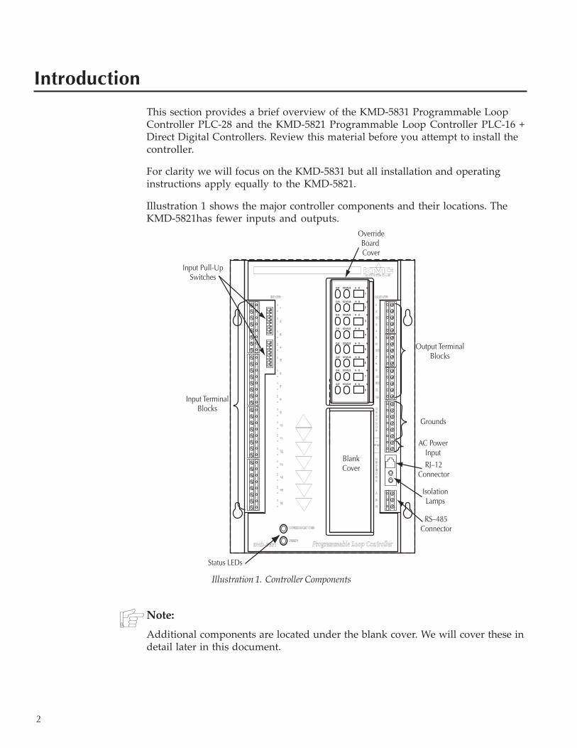
Illustration 1 shows the major controller components and their locations. TheKMD-5821has fewer inputs and outputs.
Note:
Additional components are located under the blank cover. We will cover these indetail later in this document.
Illustration 1. Controller Components
O-R STATUS H O A
O-R STATUS H O A
O-R STATUS H O A
O-R STATUS H O A
1
2
3
4
O-R STATUS H O A
O-R STATUS H O A
O-R STATUS H O A
O-R STATUS H O A
5
6
7
8
Input Terminal Blocks
Input Pull-Up Switches
RS–485 Connector
Isolation Lamps
RJ–12 Connector
Output Terminal Blocks
Grounds
Status LEDs
Blank Cover
Override Board Cover
AC Power Input
3
Installation
This section provides important instructions and guidelines for installing theKMD-5831 Programmable Loop Controller PLC-28 Direct Digital Controller.Carefully review this information prior to attempting installation.
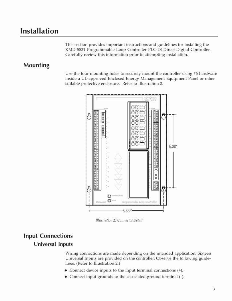
MountingUse the four mounting holes to securely mount the controller using #6 hardwareinside a UL-approved Enclosed Energy Management Equipment Panel or othersuitable protective enclosure. Refer to Illustration 2.
Input ConnectionsUniversal Inputs
Wiring connections are made depending on the intended application. SixteenUniversal Inputs are provided on the controller. Observe the following guide-lines. (Refer to Illustration 2.)◆ Connect device inputs to the input terminal connections (+).◆ Connect input grounds to the associated ground terminal (-).
Illustration 2. Connector Detail
O-R STATUS H O A
O-R STATUS H O A
O-R STATUS H O A
O-R STATUS H O A
1
2
3
4
O-R STATUS H O A
O-R STATUS H O A
O-R STATUS H O A
O-R STATUS H O A
5
6
7
8
6.00"
6.00"
4
◆ If input pull-ups are required, refer to “Configuration” later in this section.◆ Wiring terminals are suitable for up to two 12–22 AWG wires. If more than
two wires are required, use an external terminal strip for additional connec-tions.
Note:Pulse inputs may be used under the following conditions:◆ If the pulse input does not use a voltage variation, then leave the input pull-up
in the “On” position.◆ If the pulse produces voltage peaks (up to +5 VDC max.), then the input pull-
up must be set to the “Off” position.◆ The maximum pulse rate is 8 HZ (8 pulse/sec).
Connecting OutputsTwelve Universal Outputs are available for output connections labeled as 1–12 onthe output terminal blocks. The outputs are grouped into three groups of fouroutputs each with a shared grounds (labeled “SC”) in each block.. Each outputcan produce 50 mA at +12 VDC. If a greater current is required, KMC recom-mends the use of Override Boards discussed later in this section.
A separate ground block provides six additional ground connections.
Network ConnectionsThe controller provides connections for two types of RS–485 circuits.
RJ-12
The RJ–12 connector provides a six-wire RS-485 connection to a modem or PCusing the KMD-5559 CommTalk Data Exchange Module. Simply connect asuitable RJ-12 cable between the devices.
RS-485 Inputs
A RS–485 terminal is available for connections to a network of controllers If theController is at the End-of-Line, refer to “Configuration” after connections arecompleted.
Detail
The End-of-Line connection will have only one wire attached to the A and Bterminals.◆ For reliable operation, use Belden cable model #82760 or equivalent (18 gauge,
twisted, shielded, 50 picofarads or less) for all network terminal block connec-tions.
◆ Connect the nodes of the network in a daisy-chain arrangement. This means:Connect the A terminal in parallel with all other A terminals.Connect the B terminal in parallel with all other B terminals.
◆ Connect the shields of the cable together at each controller.
Installation KMD-5831 PLC-28 Direct Digital Controller Installation & Operation Guide
5
◆ Connect the shields to an earth ground (DO NOT use a chassis ground) only atone end of the segment; tape back the shield ground at the other end.
Wiring Notes
Use approved shielded cable and the following principles when connecting acontroller to a network:◆ Connect no more than 124 Tier 2 KMC addressable controllers or devices to
the RS-485 network.◆ Connect the nodes of the network in a daisy-chain arrangement. This means:
Connect the A terminal in parallel with all other A terminals.Connect the B terminal in parallel with all other B terminals.
◆ Connect the shields of the cable together at each controller.◆ Connect the shields to an earth ground at only one end of the segment; tape
back the shield ground at the other end.◆ Use a KMD–5575 repeater between every 32 Tier 2 controllers or if the cable
length of the Tier 2 network exceeds 4000 feet (1220 meters). Use no morethan seven repeaters per network.
◆ Place a KMD–5567 surge suppressor in the cable where it exits a building.
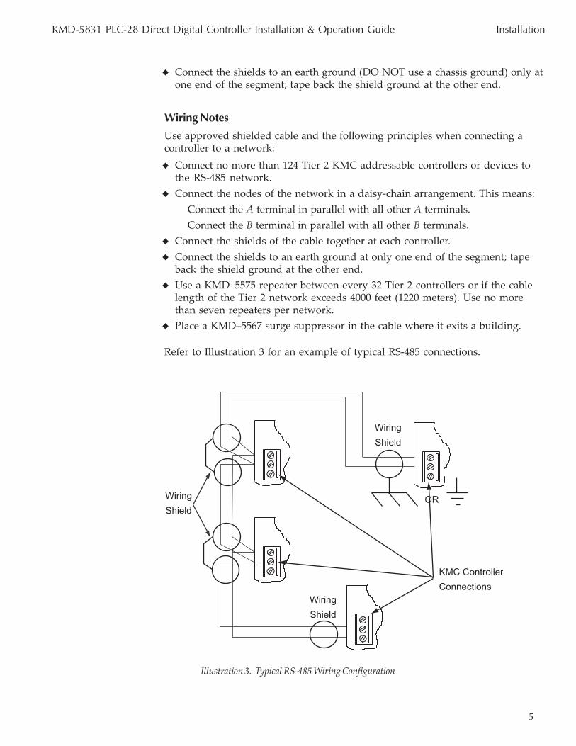
Refer to Illustration 3 for an example of typical RS-485 connections.
KMD-5831 PLC-28 Direct Digital Controller Installation & Operation Guide Installation
Illustration 3. Typical RS-485 Wiring Configuration
KMC Controller Connections
Wiring
Shield
Wiring
Shield
Wiring
Shield
OR
6
Override CardsFor large relays or devices that cannot be powered directly from a standardoutput, you will need to install an output override card. Override cards provide:
◆ a wide choice of output signals.◆ a slide switch for automatic or manual control.◆ an LED for assessment of the output state.
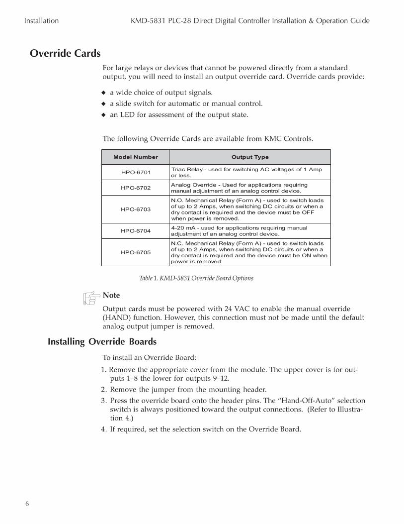
The following Override Cards are available from KMC Controls.
Note
Output cards must be powered with 24 VAC to enable the manual override(HAND) function. However, this connection must not be made until the defaultanalog output jumper is removed.
Installing Override Boards
To install an Override Board:1. Remove the appropriate cover from the module. The upper cover is for out-
puts 1–8 the lower for outputs 9–12.2. Remove the jumper from the mounting header.3. Press the override board onto the header pins. The “Hand-Off-Auto” selection
switch is always positioned toward the output connections. (Refer to Illustra-tion 4.)
4. If required, set the selection switch on the Override Board.
Installation KMD-5831 PLC-28 Direct Digital Controller Installation & Operation Guide
rebmuNledoM epyTtuptuO
1076-OPH pmA1fosegatlovCAgnihctiwsrofdesu-yaleRcairT.sselro
2076-OPH gniriuqersnoitacilpparofdesU-edirrevOgolanA.ecivedlortnocgolananafotnemtsujdalaunam
3076-OPH
sdaolhctiwsotdesu-)AmroF(yaleRlacinahceM.O.NanehwrostiucricCDgnihctiwsnehw,spmA2otpufo
FFOebtsumecivedehtdnaderiuqersitcatnocyrd.devomersirewopnehw
4076-OPH launamgniriuqersnoitacilpparofdesu-Am02-4.ecivedlortnocgolananafotnemtsujda
5076-OPH
sdaolhctiwsotdesu-)AmroF(yaleRlacinahceM.C.NanehwrostiucricCDgnihctiwsnehw,spmA2otpufonehwNOebtsumecivedehtdnaderiuqersitcatnocyrd
.devomersirewop
Table 1. KMD-5831 Override Board Options
7
Caution
DO NOT connect active 24 VAC circuits to the output block unless the associ-ated jumper is removed first. Doing so will result in damage to the output andprevent it from working.
If the associated output will be an analog output, leave the jumper in place.5. Connect output devices to the module.6. Connect required power to the input module.
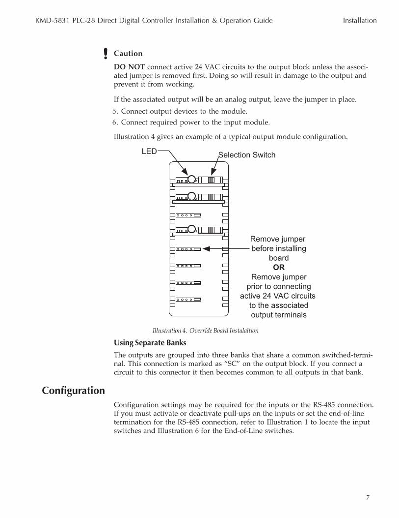
Illustration 4 gives an example of a typical output module configuration.
Using Separate Banks
The outputs are grouped into three banks that share a common switched-termi-nal. This connection is marked as “SC” on the output block. If you connect acircuit to this connector it then becomes common to all outputs in that bank.
ConfigurationConfiguration settings may be required for the inputs or the RS-485 connection.If you must activate or deactivate pull-ups on the inputs or set the end-of-linetermination for the RS-485 connection, refer to Illustration 1 to locate the inputswitches and Illustration 6 for the End-of-Line switches.
Remove jumper before installing
board OR
Remove jumper prior to connecting
active 24 VAC circuits to the associatedoutput terminals
Selection SwitchLED
Illustration 4. Override Board Instalaltion
KMD-5831 PLC-28 Direct Digital Controller Installation & Operation Guide Installation
8
Input Pull-ups
A 10K ohm resistor is available as a pull-up to a +5 VDC source voltage forpassive or ‘dry” inputs on each input circuit. The resistor is switched “On” or“Off” using the two dip-switches at the top of the controller. The top switch isassociated with the first 8 inputs and the lower switch is associated with the last 8inputs. Illustration 5 shows on of these switches in greater detail.
The default setting for each input is the “On” position. In this position, thecontroller will provide +5 VDC to the input device.
If the input is an active input, that is it has it’s own current source, the pull-up forthat input must be switched to the “Off” position.
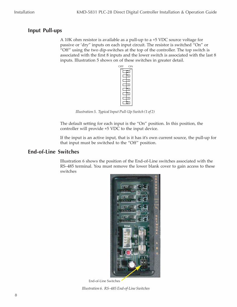
End-of-Line Switches
Illustration 6 shows the position of the End-of-Line switches associated with theRS–485 terminal. You must remove the lower blank cover to gain access to theseswitches
Illustration 5. Typical Input Pull-Up Switch (1 of 2)
OFF ONOFF ON
Illustration 6. RS–485 End-of-Line Switches
Installation KMD-5831 PLC-28 Direct Digital Controller Installation & Operation Guide
End-of-Line Switches
9
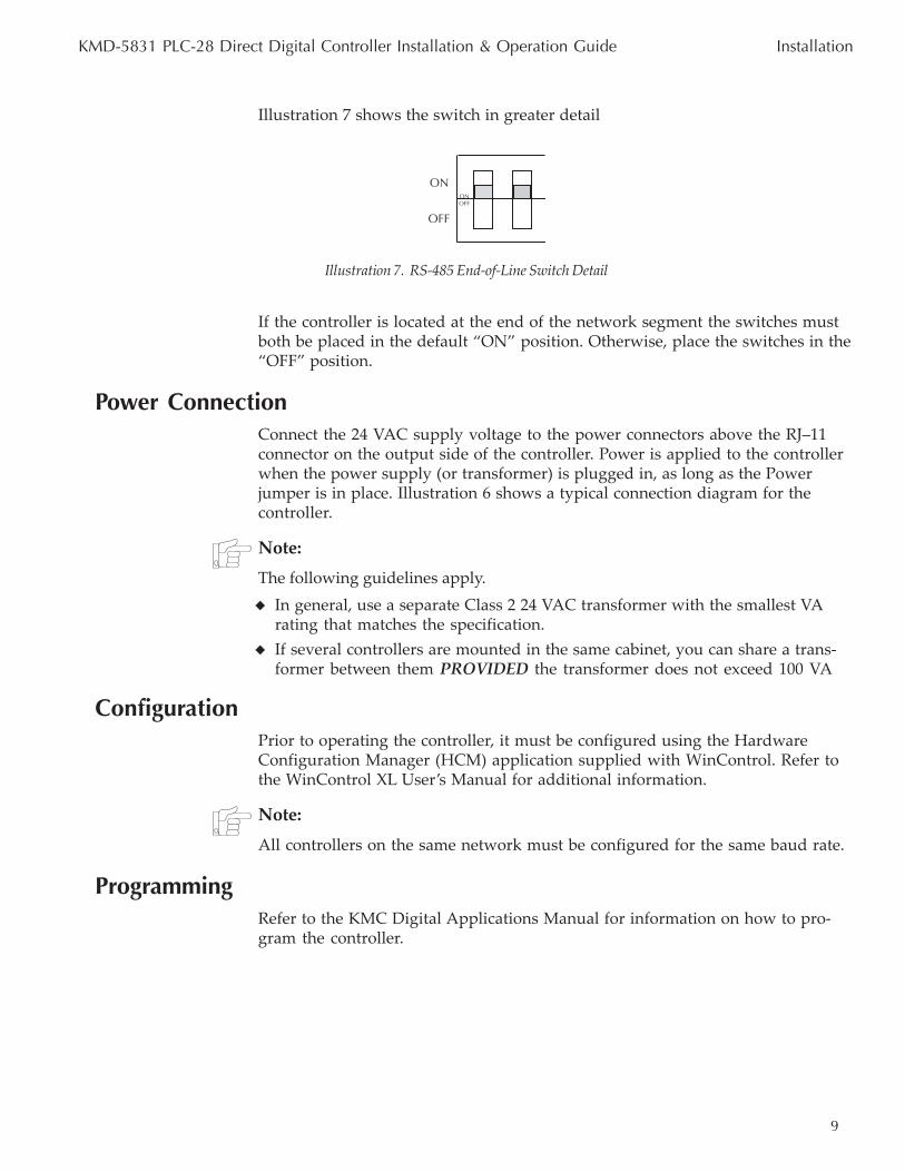
Illustration 7 shows the switch in greater detail
If the controller is located at the end of the network segment the switches mustboth be placed in the default “ON” position. Otherwise, place the switches in the“OFF” position.
Power ConnectionConnect the 24 VAC supply voltage to the power connectors above the RJ–11connector on the output side of the controller. Power is applied to the controllerwhen the power supply (or transformer) is plugged in, as long as the Powerjumper is in place. Illustration 6 shows a typical connection diagram for thecontroller.
Note:
The following guidelines apply.◆ In general, use a separate Class 2 24 VAC transformer with the smallest VA
rating that matches the specification.◆ If several controllers are mounted in the same cabinet, you can share a trans-
former between them PROVIDED the transformer does not exceed 100 VA
ConfigurationPrior to operating the controller, it must be configured using the HardwareConfiguration Manager (HCM) application supplied with WinControl. Refer tothe WinControl XL User’s Manual for additional information.
Note:
All controllers on the same network must be configured for the same baud rate.
ProgrammingRefer to the KMC Digital Applications Manual for information on how to pro-gram the controller.
OFFOFFON
ON
Illustration 7. RS-485 End-of-Line Switch Detail
KMD-5831 PLC-28 Direct Digital Controller Installation & Operation Guide Installation
10
Operation
Once configured, programmed and powered up, the controller requires verylittle user intervention.
Controls and IndicatorsThe following sections describe the controls and indicators found on the card.
Alternately, you may remove the RS-485 terminal block from the card to isolatethe card from the network without disrupting network communications to othercontrollers.
Status LEDs
Two Status LEDs are located on the bottom left side of the controller. They areused to indicate the following:
Communications – This yellow LED flashes whenever the controller is commu-nicating with other controllers over the RS-485 network connection.
Ready– This green LED indicates the controller has power and is operatingnormally. The LED will flash on and off at one second intervals.
Isolation Lamps
Two Isolation Lamps are located below the RJ–12 connector on the right side ofthe controller. These lamps serve three functions:◆ Removing the lamps will open the RS-485 circuit and isolate the controller
from the network.◆ If one, or both, lamps are lit, it indicates the network is improperly phased.
This means that the ground potential of the controller is not the same as othercontrollers on the network
◆ If the voltage or current on the network exceeds safe levels, the lamps operateas fuses to protect the controller from damage.
Power Jumper
The power jumper, shown in Illustration 8, can be used to remove power fromthe controller. This should be done anytime connections are made or changed onthe controller. Removing the jumper opens the 24 VAC supply circuit.
Resetting the ControllerIf the controller appears to be operating incorrectly, or is not responding tocommands, you may need to reset the controller.
11
Note
Resetting the controller will restore the factory default configuration. If thedevices cannot communite with the controller, or the controller cannotcommnicate with other controllers, it may be necessary to re-configure thecontroller with HCM to establish normal communications and operation. Repro-gramming may also be required.
To reset the controller, proceed as follows.
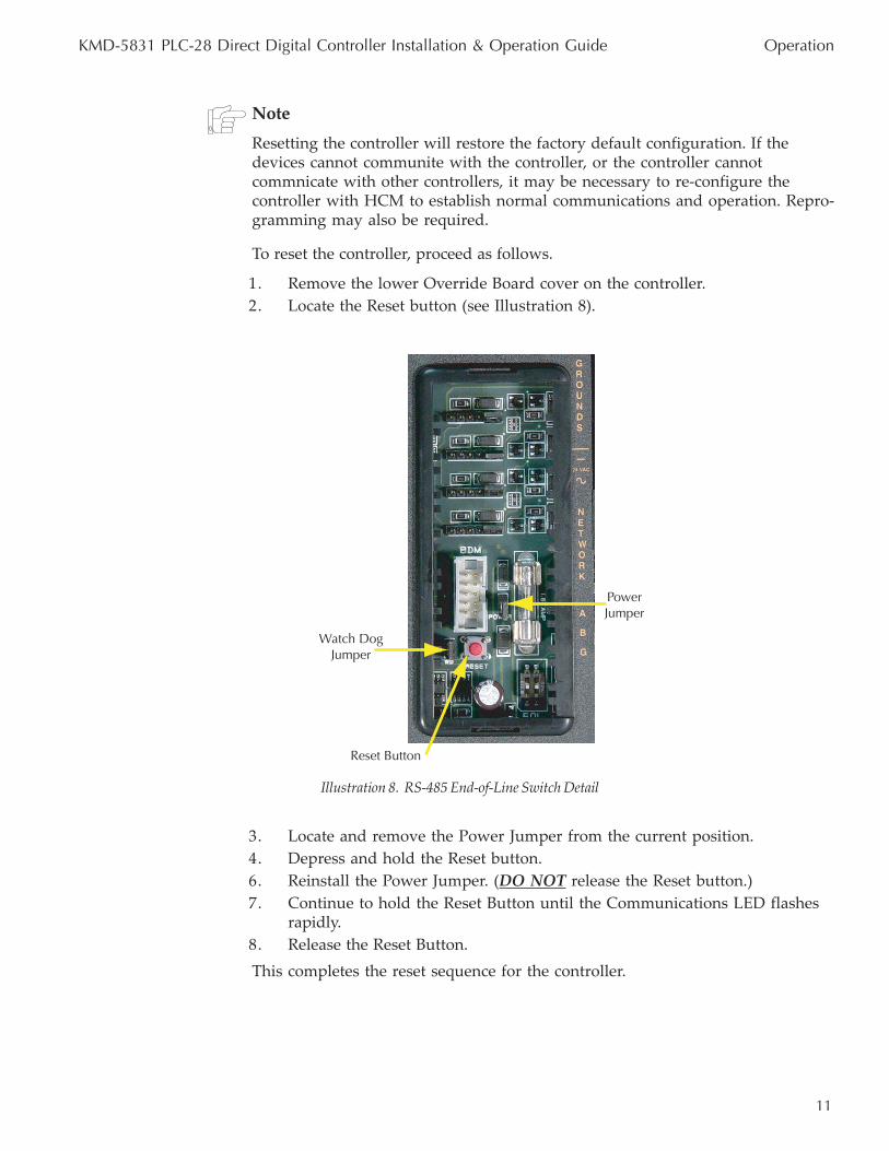
1. Remove the lower Override Board cover on the controller.2. Locate the Reset button (see Illustration 8).
3. Locate and remove the Power Jumper from the current position.4. Depress and hold the Reset button.6. Reinstall the Power Jumper. (DO NOT release the Reset button.)7. Continue to hold the Reset Button until the Communications LED flashes
rapidly.8. Release the Reset Button.This completes the reset sequence for the controller.
Illustration 8. RS-485 End-of-Line Switch Detail
KMD-5831 PLC-28 Direct Digital Controller Installation & Operation Guide Operation
Watch DogJumper
Power Jumper
Reset Button
12
DisclaimerThe material in this document is provided for information purposes only.The contents and the product(s) described herein are subject to changewithout notice. KMC Controls, Inc. makes no representations or warrantieswith respect to this document. In no event shall KMC Controls, Inc. beliable for any damages, direct or incidental, arising out of or related to theuse of this document.
Important NoticesThe KMC logo is a trademark of KMC Controls, Inc.©2003, KMC Controls,Inc. All rights reserved.
No part of this publication may be reproduced, transmitted, transcribed,stored in a retrieval system, or translated into any language in any form byany means without the written permission of KMC Controls, Inc.Printed inU.S.A.
Technical SupportIf you have any questions about this technical document or need additionaldetails, please call KMC Controls technical services at 574-831-5250 or e-mail us at [email protected].
KMC ControlsP.O. Box 497
19476 Industrial DriveNew Paris, IN 46553
U.S.A.TEL: 574.831.5250FAX: 574.831.5252
E-mail: [email protected]
902-019-04B