controls, operation, and troubleshootingdms.hvacpartners.com/docs/1005/public/0d/48_50e-1t.pdf ·...
TRANSCRIPT
Controls, Operation, and TroubleshootingCONTROLS
PageSAFETY CONSIDERATIONS . . . . . . . . . . . . . . . . . . 1GENERAL . . . . . . . . . . . . . . . . . . . . . . . . . . . . . . . . . . . 2Carrier Comfort Network (CCN) . . . . . . . . . . . . . . . 2DDC Rooftop Information . . . . . . . . . . . . . . . . . . . . . 2Major Control Components . . . . . . . . . . . . . . . . . . . 2FEATURES . . . . . . . . . . . . . . . . . . . . . . . . . . . . . . . . . 2,3Standard Features . . . . . . . . . . . . . . . . . . . . . . . . . . . 2Standard CV Only Features . . . . . . . . . . . . . . . . . . . 2Standard VAV Only Features . . . . . . . . . . . . . . . . . . 2Standard Heat Pump Only Features . . . . . . . . . . . 3Accessory Expansion Board Features . . . . . . . . . 3INPUTS/OUTPUTS AND SYSTEMINFORMATION . . . . . . . . . . . . . . . . . . . . . . . . . . . . 3,4
Base Module . . . . . . . . . . . . . . . . . . . . . . . . . . . . . . . . . 3Expansion Module . . . . . . . . . . . . . . . . . . . . . . . . . . . 3Economizer . . . . . . . . . . . . . . . . . . . . . . . . . . . . . . . . . . 3Variable Frequency Drives . . . . . . . . . . . . . . . . . . . . 4Thermistors . . . . . . . . . . . . . . . . . . . . . . . . . . . . . . . . . 4CONTROL LOGIC . . . . . . . . . . . . . . . . . . . . . . . . . . . 4,5Sequence of Operation(CV or Heat Pump Units) . . . . . . . . . . . . . . . . . . . 4
Sequence of Operation (VAV Units) . . . . . . . . . . . 4Sequence of Operation (Expansion Module) . . . 5OPERATION . . . . . . . . . . . . . . . . . . . . . . . . . . . . . . .5-24Constant Volume Operation WithThermostat . . . . . . . . . . . . . . . . . . . . . . . . . . . . . . . . 5
Cooling Control (CCN andRemote Start/Stop Only) . . . . . . . . . . . . . . . . . . . 8
Outdoor Fan Control . . . . . . . . . . . . . . . . . . . . . . . . 10Time Guards . . . . . . . . . . . . . . . . . . . . . . . . . . . . . . . . 10Economizer Operation (VAV, CV, andHeat Pump with CCN Sensors) . . . . . . . . . . . . . 11
Heating Control (CCN andRemote Start/Stop Only) . . . . . . . . . . . . . . . . . . . 12
Digital Air Volume (DAV) Linkage . . . . . . . . . . . . 13Space Temperature Reset (VAV Only) . . . . . . . . 14Space Temperature Offset (CV Only) . . . . . . . . . 15Indoor-Air Quality . . . . . . . . . . . . . . . . . . . . . . . . . . . 15Constant Volume And ModulatingPower Exhaust . . . . . . . . . . . . . . . . . . . . . . . . . . . . 17
Unoccupied Cooling Initiationand Completion . . . . . . . . . . . . . . . . . . . . . . . . . . . 17
Temperature Compensated Start . . . . . . . . . . . . . 18IAQ Pre-Occupancy Purge . . . . . . . . . . . . . . . . . . . 18Demand Limit . . . . . . . . . . . . . . . . . . . . . . . . . . . . . . . 19Defrost (Heat Pump Units Only) . . . . . . . . . . . . . . 19Smoke Control Modes . . . . . . . . . . . . . . . . . . . . . . . 20Head Pressure Control . . . . . . . . . . . . . . . . . . . . . . 20Space Temperature Sensors . . . . . . . . . . . . . . . . . 20Base And Expansion Board Modules . . . . . . . . . 21Field Test . . . . . . . . . . . . . . . . . . . . . . . . . . . . . . . . . . . 21Factory Test (Version 1.0 Only) . . . . . . . . . . . . . . 21
PageINSTALLATION . . . . . . . . . . . . . . . . . . . . . . . . . . . .25-29Control Wiring . . . . . . . . . . . . . . . . . . . . . . . . . . . . . . 25Carrier Comfort Network Interface . . . . . . . . . . . 25Optional Smoke Control . . . . . . . . . . . . . . . . . . . . . 26Remote On-Off Control . . . . . . . . . . . . . . . . . . . . . . 26Variable Frequency Drive . . . . . . . . . . . . . . . . . . . . 26Power Exhaust . . . . . . . . . . . . . . . . . . . . . . . . . . . . . . 28TROUBLESHOOTING . . . . . . . . . . . . . . . . . . . . . .30-34Complete Unit Stoppage . . . . . . . . . . . . . . . . . . . . . 30Single Circuit Stoppage . . . . . . . . . . . . . . . . . . . . . 30Stoppage Restart Procedure . . . . . . . . . . . . . . . . 30Alarm Codes And Problem Identification . . . . . 30CCN DEVICE CONFIGURATION . . . . . . . . . . . .34-40COOLING CAPACITY STAGING TABLES . . . . . . 41THERMISTOR RESISTANCE TABLES . . . . . . .42,43
SAFETY CONSIDERATIONS
Before performing service or maintenance operations onunit, turn off and lock off main power switch to unit.Electrical shock could cause personal injury.
Installation and servicing of air-conditioning equipmentcan be hazardous due to system pressure, flammable gases,and electrical components. Only trained and qualified serv-ice personnel should install, repair, or service air-conditioningequipment.Untrained personnel can perform the basic maintenance
functions of cleaning coils and filters and replacing filters.All other operations should be performed by trained servicepersonnel.When working on air-conditioning equipment, ob-serve precautions in the literature, tags and labels attachedto the unit, and other safety precautions that may apply.Follow all safety codes.Wear safety glasses andwork gloves.
Use quenching cloth for unbrazing operations. Have fire ex-tinguishers available for all brazing operations.
This unit uses a microprocessor-based electronic con-trol system.Do not use jumpers or other tools to shortout components, or to bypass or otherwise depart fromrecommended procedures. Any short-to-ground of thecontrol board or accompanying wiring may destroy theelectrical components.
48/50EJ,EK,EW,EY024-06850EJQ,EWQ024 and 028
Single-Package Heating/Cooling Unitsand Single-Package Heat Pump Units
Manufacturer reserves the right to discontinue, or change at any time, specifications or designs without notice and without incurring obligations.Book 1 1 1Tab 1a 1b 5a
PC 111 Catalog No. 534-890 Printed in U.S.A. Form 48/50E-1T Pg 1 3-98 Replaces: New
GENERALIMPORTANT: This literature contains controls, op-eration, and troubleshooting data for 48/50EJ, EK, EW,EY rooftop units and 50EJQ, EWQ heat pump units.Use this guide in conjunction with the separate Instal-lation Instructions literature packaged with the unit.
Carrier Comfort Network (CCN) — Carrier HVAC(heating ventilation and air conditioning) and other buildingequipment being controlled by DDC (direct digital controls)have the inherent ability to talk on a common communi-cation bus or network. The configuration of the com-munication bus with 2 or more DDC controlled pieces ofequipment is referred to as theCarrier Comfort Network (CCN)system. The CCN communication bus conveys commands,data, and alarms between all elements, regardless of theirphysical locations. The communication bus consists of a field-supplied, shielded, 3-conductor cable connected in daisy-chain fashion.The main human interface with the CCN system is the
Service Tool software, although Building Supervisor orComfortWorks™ software can also be used.NOTE: An IBM PC compatible computer equipped withCarrier controls software is required to connect to the DDCcontrol.The Building Supervisor consists of an IBM PC compat-
ible computer equipped with Carrier controls software thatallows it to connect to the communications bus and com-municate directly with any equipment connected to thenetwork. An operator working at a PC with Building Su-pervisor, Service Tool or ComfortWorks software can com-mand, monitor, configure, or modify any portion of the sys-tem. More than one Building Supervisor can be used. TheBuilding Supervisor, in conjunction with optional networkproducts, can generate a wide variety of managerial reportswhich reflect the operational characteristics of one or morebuildings.NOTE: The DDC board isNOT compatible with the HSIOused on other products.
DDC Rooftop Information — Precise control is pro-vided for stand-alone operation of HVAC equipment by afactory-installed processor. Carrier 48/50EJ,EK,EW,EY and50EJQ,EWQ units contain factory-installed Direct DigitalControls (DDC) integrated into the product. The standardproduct includes a base module board as well as an acces-sory expansion module board. The unit is CCN compatiblewith both the base module board and the expansion moduleboard. The optional expansion module board is not requiredfor CCN compatibility. Sensors that monitor equipmentoperation and conditions in the occupied space are con-nected to the standard processor board in the unit, and out-puts from the processor board serve to control unit opera-tion. Each DDC equipped unit is shipped from the factorywith all applicable control hardware and software installedand ready for start-up.TheDDC rooftop controls cycle evaporator-fanmotor, com-
pressors, and unloaders to maintain the proper temperatureconditions. The controls also cycle condenser fans to main-tain suitable head pressure. Safeties are continuously moni-tored to prevent the unit from operating under abnormalconditions. The controls cycle heat as required, provide con-trol of economizer and power exhaust, and initiate the vari-able frequency drive.A scheduling function, programmed by the user, controls
the unit occupied/unoccupied schedule. The control can alsobe in the unoccupied schedule and put into the occupied sched-ule through a remote 24-v AC signal. The DDC control alsoallows the service person to operate a field test so that all the
base unit controlled components can be checked for properoperation. The field test can be performed without the aid ofa personal computer and Building Supervisor, Service Toolor ComfortWorks software.
Major Control Components — The control systemconsists of the following components:• standard base module board• accessory expansion module board• accessory enthalpy sensor• thermistors• space temperature sensors (accessory T-55, T-56)• accessory supply-air fan status switch• accessory check filter switch• accessory air quality (AQ) sensor (used either indoors oroutdoors)
• accessory 2-stage heat/2-stage cool room thermostat
FEATURESStandard Features• control of an outdoor (condenser) fan based upon outdoor-air temperature
• control of modulating economizer damper to provide freecooling when outdoor conditions are suitable, using supply-air temperature (SAT) as a control point
• support of remote occupied/unoccupied input to start/stopthe unit
• control of the economizer damper and indoor fan to obtainunoccupied free cooling
• control of 2 stages of CV (constant volume) powerexhaust
• provide power exhaust output to an external power ex-haust controller
• perform demand limit functions based upon CCN load-shed commands
• alarm monitoring of all key parameters• CCN protocol• timeclock with backup (supports hour, minute, day of week,month, date, and year)
• daylight savings time function• occupancy control with 8 periods for unit operation• holiday table containing up to 18 holidays• ability to initiate timed override from T-55 device• support a factory- and field-test for end of line productionand field check out
• temperature compensated start to calculate early start timebefore occupancy
• support a set of Display, Maintenance, Configuration, Serv-ice, and Set Point data tables for interface with BuildingSupervisor, Service Tool or ComfortWorks software
Standard CV (Constant Volume) Only Features• control using Y1, Y2, W1, W2, G thermostat inputs• cooling capacity control of 2 stages plus economizer with2 compressors to maintain space temperature to an occu-pied or unoccupied set point
• control of up to 2 stages of gas or electric heat to maintainspace temperature to an occupied or unoccupied set point
• enable heating or cooling during unoccupied periods asrequired to maintain space temperature within the unoc-cupied set points
• ability to initiate timed override from T-56 device• control of the indoor fan• adjustment of space temperature set points ±5° F whenusing T-56 sensor
Standard VAV (Variable Air Volume) OnlyFeatures• cooling capacity control of 6 stages plus economizer with2 compressors and 2 unloaders to maintain supply-airtemperature at supply-air set point during occupiedperiods
2
• control of one stage of gas or electric heat tomaintain supply-air temperature at supply-air set point during occupiedperiods
• ability to use multiple space temperature sensors to aver-age space temperature
• support linkage function for interface with DAV (DigitalAir Volume) systems
• enable heating or cooling during unoccupied periods asrequired
• provide space temperature reset to reset the supply-air setpoint upward when temperature falls below its occupiedcooling set point (space temperature sensor is required)
• provide space temperature reset to reset the supply air setpoint upward from a remote 4 to 20 mA signal
• provide VFD (variable frequency drive) enable high volt-age relay output to enable VFD
• control of heat interlock relay
Standard Heat Pump Only Features• control compressors and reversing valve solenoids as firststage of heating
• control heat stages 1 and 2 as second stage heating or asemergency heat
• control of both outdoor fans during heating• provide defrost cycles during heating
Accessory Expansion Board Features• control of modulating economizer damper to maintainindoor-air quality when outdoor conditions are suitable
• provide discrete inputs for fan status, filter status, fieldapplied status, and demand limit
• provide demand limit functions based upon the state ofthe discrete input
• provide an output for the external alarm light indicator• smoke control modes including evacuation, smoke purge,pressurization, and fire shutdown
• provide power exhaust fire outputs for direct control ofmodulated power exhaust stages during fire/smoke modes
INPUTS/OUTPUTS ANDSYSTEM INFORMATION
The DDC board contains the factory-loaded software thatmonitors and processes the following inputs, outputs and sys-tem information:• INPUTS:− thermistors− switches− remote 4 to 20 mA signal
• OUTPUTS (CV OPERATION):− condenser fan contactors− indoor-fan relay− compressors stages 1 and 2− crankcase heaters− heat stages 1 and 2 operation− economizer motor (4 to 20 mA)− optional non-modulating power exhaust− optional modulating power exhaust enable
• OUTPUTS (VAV OPERATION):− condenser fan contactors− indoor-fan relay/variable frequency drive enable− compressors and unloading stages 1 through 6− crankcase heaters− heat relay− heat interlock relay− economizer motor (4 to 20 mA)− optional non-modulating power exhaust (Version3.0 software)
− optional modulating power exhaust enable
• OUTPUTS (HEAT PUMP OPERATION):− condenser fan contactors− indoor-fan relay− compressors stages 1 and 2− crankcase heaters− heat stages 1 and 2 operation− economizer motor (4 to 20 mA)− optional power exhaust− reversing valve solenoids− outputs to Y for defrost
• OUTPUTS (EXPANSION MODULE):− alarm light− power exhaust override− smoke control modes− IAQ/OAQ (indoor air quality/outdoor air quality) ven-tilation modes
NOTE: Software resides in non-volatile memory in the DDC;memory will not be lost with an extended power failure. Thereare no batteries to replace over time.• SYSTEM INFORMATION:− generates alert and alarm information (via sensorinputs)
− supports level II communications− supports digital air volume (DAV) interface (48/50EK,EY only)
− maintain service history• ACCESSORY EXPANSION MODULE — The expan-sion module is a field-installed accessory. Through inputand output channels on the module, it supports the sensorsand inputs used for:− fan status− filter status− field applied status− demand limit− fire unit shutdown− fire pressurization− fire evacuation− fire smoke purge− IAQ/OAQ
Base Module — The base unit module closes contactsto energize the compressors, crankcase heaters, and the evapo-rator fan motor (CV or heat pump) or enable the variablefrequency drive (VAV). Triacs are used to energize the heatrelays, heat interlock relay (VAV), outdoor fans, compressorunloaders (VAV), and reversing valve relays (HP), and en-able the optional power exhaust. A room thermostat or roomsensor, optional outside air enthalpy, outdoor-air thermistor,supply-air thermistors, and compressor switches (compres-sor safety circuit) provide inputs to this module. When usedwith a room sensor, a remote start/stop input can be used tooverride the occupancy schedule.
Expansion Module — On the expansion module, thetriacs are used to turn on an alarm light, jumper the modu-lating power exhaust sequencers, and force the power ex-haust motors on when necessary in the fire/smoke mode. Anaccessory fan status switch, accessory filter status switch,accessory field applied status switch, an accessory indoor-air quality switch, and an accessory outdoor-air quality switchas well as accessory fire unit shutdown, pressurization, evacu-ation and smoke purge switches provide input to the expan-sion module. Demand limit can be provided through a 24-vinput.
Economizer — The DDC controls output a 4 to 20 mAsignal to the actuator in the unit to modulate it as requiredby the control algorithm. Damper is a spring-return type toallow automatic closing of the damper on power loss.
3
Variable Frequency Drives — The evaporator fan iscontrolled by a variable frequency drive (VFD). The outputthat normally controls the indoor-fan motor (CV/HP) en-ables the variable frequency drive.
Thermistors — The unit control system gathers infor-mation from the sensors to control the operation of the unit.
CONTROL LOGICThe following describes the general control logic se-
quence of operation for CV,VAV, and heat pump units. Theinitialization software in each base control module deter-mines CV or VAV operation from DIP (dual in-line package)switch no. 1 and thermostat or sensor (CCN) operation fromDIP switch no. 2 on the control module.
Sequence of Operation (CV or Heat PumpUnits)1. The control module is powered up.2. All internal software parameters are initialized.3. All alarms and alerts are cleared.4. The Input/Output database is re-mapped for CV
operation.5. Maximum heat stages is set to 2.6. Maximum cool stages is set to 3.7. DIP switch no. 3 is read. If the Switch is OPEN, the
internal flag is set for expansion board operation.8. If thermostat operation is selected (DIP switch no. 2 set
to CLOSED), thermostat-based control is performed bymonitoring the Y1, Y2, W1, W2, and G inputs and con-trolling the economizer, Cool 1, Cool 2, Heat 1, Heat 2,and Indoor Fan accordingly, while maintaining requiredtime guards and delays when cycling equipment. Thefirst time after control power-up, the indoor fan is de-layed by a random 1 to 63 seconds.
9. If thermostat operation is not selected (DIP switch no.2 set to OPEN), occupancy state is determined based onTime Schedules or Remote Occupied/Unoccupied in-put. If Temperature Compensated Start is active the unitwill be controlled as in Occupied mode.
10. The occupied or unoccupied comfort set points are read.The space temperature offset input is used, if present.
11. The appropriate operating mode and fan control is setbased on conditioned space temperature and user con-figured set points. The indoor fan will turn ON if theunit is in Occupied mode or if the unit is in Unoccupiedmode and the space temperature is outside of the un-occupied comfort set points (Unoccupied Heat or Un-occupied Cool).When the unit goes into Occupiedmode,the start of the indoor fan is delayed by a random 1 to63 seconds. The random delay will be applied to the firstfan start after control power-up, regardless of the oper-ating mode.
12. The space temperature is monitored against the comfortset points and heating or cooling stages are controlledas required.
13. If the unit is in Occupied mode, Economizer control isperformed.
14. If the unit is in Unoccupied mode, Unoccupied FreeCooling and IAQ Pre-Occupancy purge are performedas required.
15. If DX (direct expansion) cooling is on, Outdoor Fan Con-trol is performed.
16. Two stages of CV power exhaust are controlled by theeconomizer position or PowerExhaust Enable output basedon indoor fan state. Power exhaust operation is selectedby DIP switch no. 5.
17. The control will run Diagnostics to monitor alarms andalerts at all times.
18. The control will respond to CCN communications andperform any configured network POC (Product Out-board Control) functions such as Time/OAT Broadcastand Global Occupancy Broadcast.
19. In heat pump units, the control will monitor defrostinputs during heating and perform defrost cycles asrequired.
Sequence of Operation (VAV Units)1. The control module is powered up.2. All internal software parameters are initialized.3. All alarms/alerts are cleared.4. The Input/Output database is re-mapped for VAV
operation.5. The maximum heat stages is set to 1.6. The maximum cool stages is set to 6 (plus economizer).7. The DIP switch no. 3 is read. If the DIP switch is open,
the internal flag is set for expansion board operation.8. The control will determine if Linkage is active and if
the unit will operate in DAVmode. If yes, the local com-fort set points will be replaced and space temperature,return-air temperature, and occupancy status will be sup-plied with linkage data.
9. The occupancy state is determined based on Time Sched-ules, Remote Occupied/Unoccupied input, Global occu-pancy, or DAV. If the Temperature Compensated Start isactive the unit will be controlled as in Occupied mode.
10. The control will set appropriate operating mode and fancontrol. The Variable Frequency Drive (VFD) will beturned ON if the unit is in Occupied mode. If the unit isin Unoccupied mode and the space temperature readingis available (either from sensor or DAV), the set pointtemperature (SPT) is monitored against the unoccupiedheat and cool set points. The VFD is started wheneverSPT is outside of the set points (Unoccupied Heat orUnoccupiedCool). TheVFDmay also be started byNight-time thermostat via remote Occupied/Unoccupied Inputor by theTemperatureCompensatedStart algorithm.Whenthe unit goes into Occupied mode or the first time afterpower-up, the start of the VFD is delayed by a random1 to 63 seconds.
11. When the VFD is running in a normal mode, the controlwill start Heating or Cooling as required to maintainSupply-Air Temperature (SAT) at Supply-Air Set Pointplus reset. The reset value is determined by the SAT re-set and the Space Temperature Reset algorithms.
12. When the indoor fan is ON, the Power Exhaust Enableoutput will energize the external Modulated Power Ex-haust controller.
13. When in Heating mode, the Heat Interlock Relay outputis energized to drive the VAV boxes open.
14. If the unit is in Occupied mode, Economizer control isperformed.
15. If the unit is in Unoccupied mode, the control will per-form Unoccupied Free Cool and IAQ Pre-Occupancypurge as required.
16. If DX (direct expansion) cooling is on, the control willperform Outdoor Fan control.
17. The control will run Diagnostics to monitor alarms andalerts at all times.
18. The control will respond to CCN communications andperform any configured network POC (Product Out-board Control) functions such as Time/OAT Broadcastand Global Occupancy Broadcast.
4
Sequence of Operation (Expansion Module) —For CV, VAV, or heat pump units equipped with optional ex-pansion I/O (input/output) board, the following functions willbe added to the sequence:1. The expansion control board will perform a periodic SIO
scan and maintain I/O database expanded I/O points.2. Fire/Smoke Control is performed.3. If the unit is in Occupied mode (or indoor fan is ON for
thermostat units), the expansion control board will per-form IAQ control.
4. The fan, filter, demand limit, and field-applied status ismonitored.
OPERATION
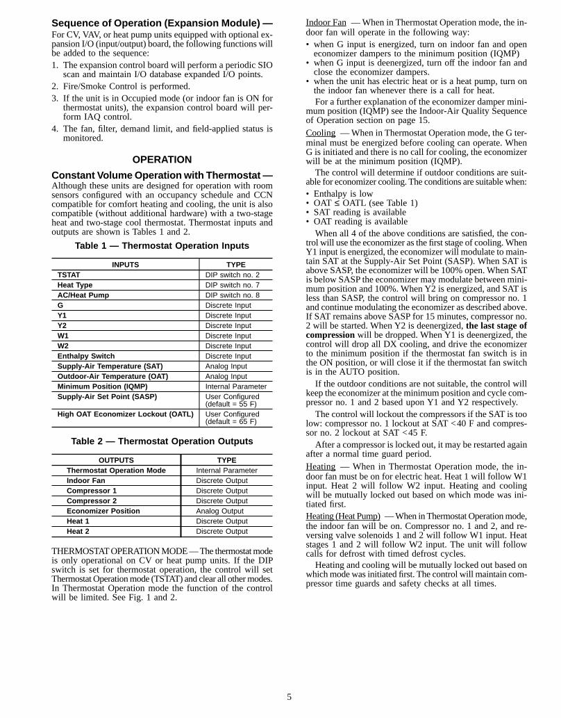
Constant VolumeOperation with Thermostat—Although these units are designed for operation with roomsensors configured with an occupancy schedule and CCNcompatible for comfort heating and cooling, the unit is alsocompatible (without additional hardware) with a two-stageheat and two-stage cool thermostat. Thermostat inputs andoutputs are shown is Tables 1 and 2.
Table 1 — Thermostat Operation Inputs
INPUTS TYPETSTAT DIP switch no. 2Heat Type DIP switch no. 7AC/Heat Pump DIP switch no. 8G Discrete InputY1 Discrete InputY2 Discrete InputW1 Discrete InputW2 Discrete InputEnthalpy Switch Discrete InputSupply-Air Temperature (SAT) Analog InputOutdoor-Air Temperature (OAT) Analog InputMinimum Position (IQMP) Internal ParameterSupply-Air Set Point (SASP) User Configured
(default = 55 F)High OAT Economizer Lockout (OATL) User Configured
(default = 65 F)
Table 2 — Thermostat Operation Outputs
OUTPUTS TYPEThermostat Operation Mode Internal ParameterIndoor Fan Discrete OutputCompressor 1 Discrete OutputCompressor 2 Discrete OutputEconomizer Position Analog OutputHeat 1 Discrete OutputHeat 2 Discrete Output
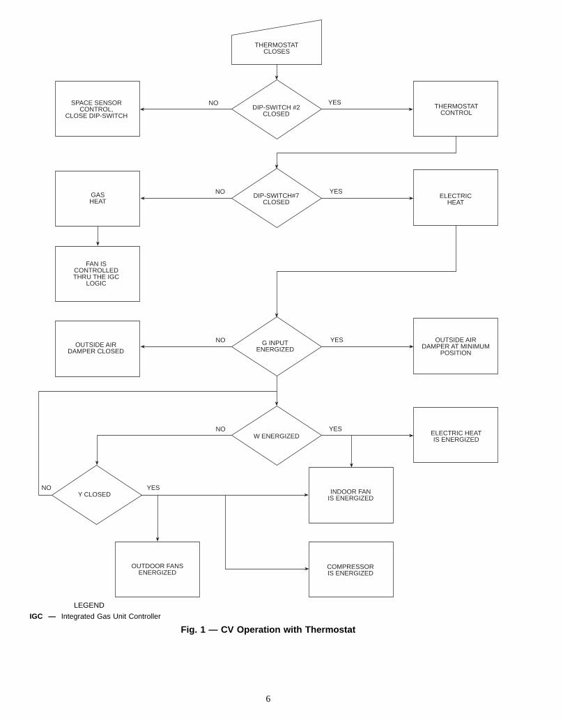
THERMOSTATOPERATIONMODE—The thermostatmodeis only operational on CV or heat pump units. If the DIPswitch is set for thermostat operation, the control will setThermostatOperationmode (TSTAT) and clear all othermodes.In Thermostat Operation mode the function of the controlwill be limited. See Fig. 1 and 2.
Indoor Fan —When in Thermostat Operation mode, the in-door fan will operate in the following way:• when G input is energized, turn on indoor fan and openeconomizer dampers to the minimum position (IQMP)
• when G input is deenergized, turn off the indoor fan andclose the economizer dampers.
• when the unit has electric heat or is a heat pump, turn onthe indoor fan whenever there is a call for heat.For a further explanation of the economizer damper mini-
mum position (IQMP) see the Indoor-Air Quality Sequenceof Operation section on page 15.Cooling —When in Thermostat Operation mode, the G ter-minal must be energized before cooling can operate. WhenG is initiated and there is no call for cooling, the economizerwill be at the minimum position (IQMP).The control will determine if outdoor conditions are suit-
able for economizer cooling. The conditions are suitable when:• Enthalpy is low• OAT ≤ OATL (see Table 1)• SAT reading is available• OAT reading is availableWhen all 4 of the above conditions are satisfied, the con-
trol will use the economizer as the first stage of cooling.WhenY1 input is energized, the economizer will modulate to main-tain SAT at the Supply-Air Set Point (SASP). When SAT isabove SASP, the economizer will be 100% open. When SATis below SASP the economizer may modulate between mini-mum position and 100%. When Y2 is energized, and SAT isless than SASP, the control will bring on compressor no. 1and continue modulating the economizer as described above.If SAT remains above SASP for 15 minutes, compressor no.2 will be started. When Y2 is deenergized,the last stage ofcompressionwill be dropped. When Y1 is deenergized, thecontrol will drop all DX cooling, and drive the economizerto the minimum position if the thermostat fan switch is inthe ON position, or will close it if the thermostat fan switchis in the AUTO position.If the outdoor conditions are not suitable, the control will
keep the economizer at the minimum position and cycle com-pressor no. 1 and 2 based upon Y1 and Y2 respectively.The control will lockout the compressors if the SAT is too
low: compressor no. 1 lockout at SAT <40 F and compres-sor no. 2 lockout at SAT <45 F.After a compressor is locked out, it may be restarted again
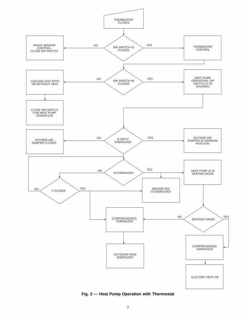
after a normal time guard period.Heating — When in Thermostat Operation mode, the in-door fan must be on for electric heat. Heat 1 will follow W1input. Heat 2 will follow W2 input. Heating and coolingwill be mutually locked out based on which mode was ini-tiated first.Heating (Heat Pump) —When inThermostatOperationmode,the indoor fan will be on. Compressor no. 1 and 2, and re-versing valve solenoids 1 and 2 will follow W1 input. Heatstages 1 and 2 will follow W2 input. The unit will followcalls for defrost with timed defrost cycles.Heating and cooling will be mutually locked out based on
whichmodewas initiated first. The control will maintain com-pressor time guards and safety checks at all times.
5
SPACE SENSORCONTROL,
CLOSE DIP-SWITCH
DIP-SWITCH#7CLOSED
THERMOSTATCLOSES
DIP-SWITCH #2CLOSED
NO YESTHERMOSTAT
CONTROL
ELECTRICHEAT
OUTSIDE AIRDAMPER AT MINIMUM
POSITION
ELECTRIC HEATIS ENERGIZED
INDOOR FANIS ENERGIZED
COMPRESSORIS ENERGIZED
OUTDOOR FANSENERGIZED
NOY CLOSED
OUTSIDE AIRDAMPER CLOSED
FAN ISCONTROLLEDTHRU THE IGC
LOGIC
GASHEAT
G INPUTENERGIZED
W ENERGIZEDYESNO
YES
NO YES
NO YES
LEGEND
IGC — Integrated Gas Unit Controller
Fig. 1 — CV Operation with Thermostat
6
DIP-SWITCH #8CLOSED
NO YESCOOLING UNIT WITHOR WITHOUT HEAT
HEAT PUMPOPERATION, DIP
SWITCH #7 ISIGNORED
SPACE SENSORCONTROL,
CLOSE DIP-SWITCH
THERMOSTATCLOSES
DIP-SWITCH #2CLOSED
NO YESTHERMOSTAT
CONTROL
CLOSE DIP SWITCHFOR HEAT PUMP
OPERATION
OUTSIDE AIRDAMPER AT MINIMUM
POSITIONOUTSIDE AIR
DAMPER CLOSEDG INPUT
ENERGIZEDNO YES
NO
W ENERGIZEDYESNO
YES
HEAT PUMP IS INHEATING MODE
Y CLOSEDINDOOR FAN
IS ENERGIZED
OUTDOOR FANSENERGIZED
COMPRESSOR(S) ENERGIZED
DEFROST MODENO YES
COMPRESSOR(S) ENERGIZED
ELECTRIC HEAT ON
Fig. 2 — Heat Pump Operation with Thermostat
7
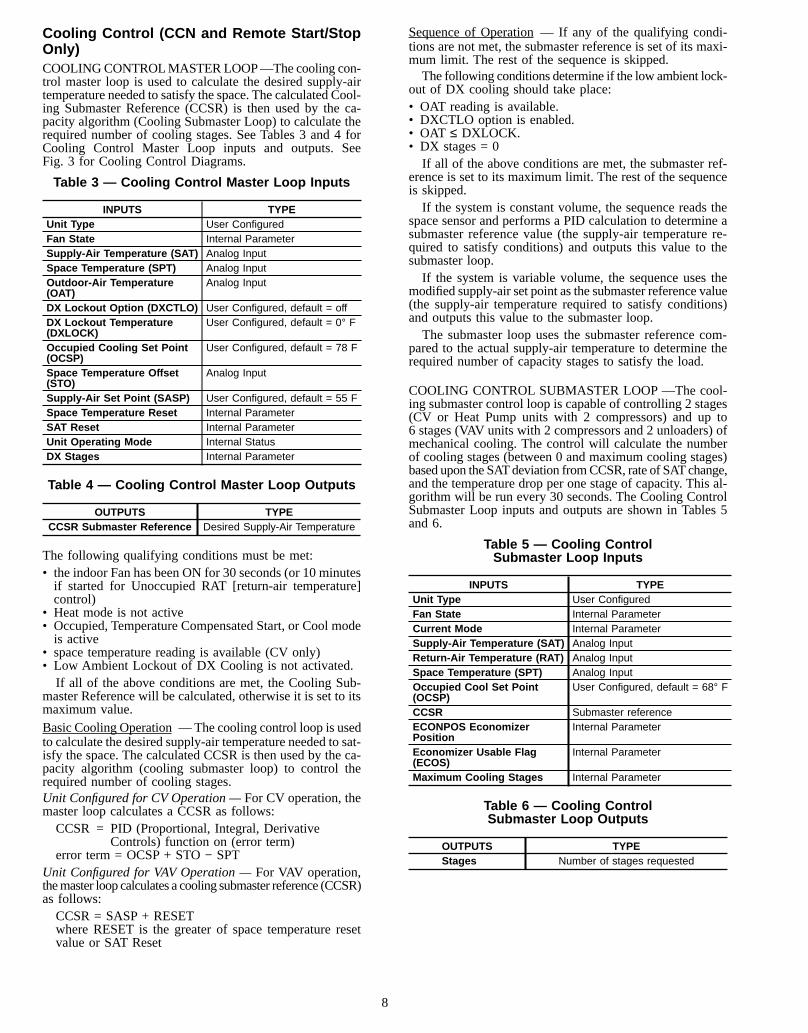
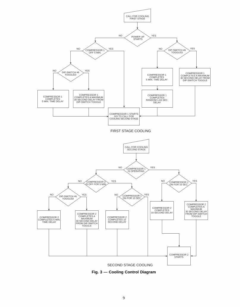
Cooling Control (CCN and Remote Start/StopOnly)COOLINGCONTROLMASTER LOOP—The cooling con-trol master loop is used to calculate the desired supply-airtemperature needed to satisfy the space. The calculated Cool-ing Submaster Reference (CCSR) is then used by the ca-pacity algorithm (Cooling Submaster Loop) to calculate therequired number of cooling stages. See Tables 3 and 4 forCooling Control Master Loop inputs and outputs. SeeFig. 3 for Cooling Control Diagrams.
Table 3 — Cooling Control Master Loop Inputs
INPUTS TYPEUnit Type User ConfiguredFan State Internal ParameterSupply-Air Temperature (SAT) Analog InputSpace Temperature (SPT) Analog InputOutdoor-Air Temperature(OAT)
Analog Input
DX Lockout Option (DXCTLO) User Configured, default = offDX Lockout Temperature(DXLOCK)
User Configured, default = 0° F
Occupied Cooling Set Point(OCSP)
User Configured, default = 78 F
Space Temperature Offset(STO)
Analog Input
Supply-Air Set Point (SASP) User Configured, default = 55 FSpace Temperature Reset Internal ParameterSAT Reset Internal ParameterUnit Operating Mode Internal StatusDX Stages Internal Parameter
Table 4 — Cooling Control Master Loop Outputs
OUTPUTS TYPECCSR Submaster Reference Desired Supply-Air Temperature
The following qualifying conditions must be met:• the indoor Fan has been ON for 30 seconds (or 10 minutesif started for Unoccupied RAT [return-air temperature]control)
• Heat mode is not active• Occupied, Temperature Compensated Start, or Cool modeis active
• space temperature reading is available (CV only)• Low Ambient Lockout of DX Cooling is not activated.If all of the above conditions are met, the Cooling Sub-
master Reference will be calculated, otherwise it is set to itsmaximum value.Basic Cooling Operation —The cooling control loop is usedto calculate the desired supply-air temperature needed to sat-isfy the space. The calculated CCSR is then used by the ca-pacity algorithm (cooling submaster loop) to control therequired number of cooling stages.Unit Configured for CV Operation —For CV operation, themaster loop calculates a CCSR as follows:CCSR = PID (Proportional, Integral, Derivative
Controls) function on (error term)error term = OCSP + STO − SPT
Unit Configured for VAV Operation —For VAV operation,themaster loop calculates a cooling submaster reference (CCSR)as follows:CCSR = SASP + RESETwhere RESET is the greater of space temperature resetvalue or SAT Reset
Sequence of Operation — If any of the qualifying condi-tions are not met, the submaster reference is set of its maxi-mum limit. The rest of the sequence is skipped.The following conditions determine if the low ambient lock-
out of DX cooling should take place:• OAT reading is available.• DXCTLO option is enabled.• OAT ≤ DXLOCK.• DX stages = 0If all of the above conditions are met, the submaster ref-
erence is set to its maximum limit. The rest of the sequenceis skipped.If the system is constant volume, the sequence reads the
space sensor and performs a PID calculation to determine asubmaster reference value (the supply-air temperature re-quired to satisfy conditions) and outputs this value to thesubmaster loop.If the system is variable volume, the sequence uses the
modified supply-air set point as the submaster reference value(the supply-air temperature required to satisfy conditions)and outputs this value to the submaster loop.The submaster loop uses the submaster reference com-
pared to the actual supply-air temperature to determine therequired number of capacity stages to satisfy the load.
COOLING CONTROL SUBMASTER LOOP —The cool-ing submaster control loop is capable of controlling 2 stages(CV or Heat Pump units with 2 compressors) and up to6 stages (VAV units with 2 compressors and 2 unloaders) ofmechanical cooling. The control will calculate the numberof cooling stages (between 0 and maximum cooling stages)based upon the SATdeviation fromCCSR, rate of SATchange,and the temperature drop per one stage of capacity. This al-gorithm will be run every 30 seconds. The Cooling ControlSubmaster Loop inputs and outputs are shown in Tables 5and 6.
Table 5 — Cooling ControlSubmaster Loop Inputs
INPUTS TYPEUnit Type User ConfiguredFan State Internal ParameterCurrent Mode Internal ParameterSupply-Air Temperature (SAT) Analog InputReturn-Air Temperature (RAT) Analog InputSpace Temperature (SPT) Analog InputOccupied Cool Set Point(OCSP)
User Configured, default = 68° F
CCSR Submaster referenceECONPOS EconomizerPosition
Internal Parameter
Economizer Usable Flag(ECOS)
Internal Parameter
Maximum Cooling Stages Internal Parameter
Table 6 — Cooling ControlSubmaster Loop Outputs
OUTPUTS TYPEStages Number of stages requested
8
POWER UP STARTS
YESNO
NOYES YESDIP-SWITCH #6
TOGGLED
COMPRESSOR 1COMPLETES A MAXIMUM30 SECOND DELAY FROM
DIP-SWITCH TOGGLE
COMPRESSOR 1COMPLETES
5 MIN. TIME DELAY
COMPRESSOR 1COMPLETES
RANDOM 1-63 SEC.DELAY
COMPRESSOR 1 STARTSGO TO CALL FOR
COOLING SECOND STAGE
COMPRESSOR 1COMPLETES A MAXIMUM30 SECOND DELAY FROM
DIP-SWITCH TOGGLE
COMPRESSOR 1COMPLETES
5 MIN. TIME DELAY
COMPRESSOR 1OFF 5 MIN.
NO
YESNODIP-SWITCH #6
TOGGLED
FIRST STAGE COOLING
CALL FOR COOLINGFIRST STAGE
COMPRESSOR 1IS OPERATING
YESNO
YES
NO COMPRESSOR 1ON FOR 10 SEC.
NO
YES
COMPRESSOR 2IS OFF FOR 5 MIN.
DIP-SWITCH #6TOGGLED
NO
COMPRESSOR 2COMPLETES 5 MIN.
TIME DELAY
COMPRESSOR 2COMPLETES A
MAXIMUM30 SECOND DELAYFROM DIP-SWITCH
TOGGLE
COMPRESSOR 2COMPLETES 10SECOND DELAY
COMPRESSOR 2COMPLETES
10 SECOND DELAY
COMPRESSOR 2COMPLETES A
MAXIMUM30 SECOND DELAYFROM DIP-SWITCH
TOGGLE
COMPRESSOR 2STARTS
NO YESCOMPRESSOR 1ON FOR 10 SEC.
YES
SECOND STAGE COOLING
CALL FOR COOLINGSECOND STAGE
Fig. 3 — Cooling Control Diagram
9
The following qualifying conditions must be met for theCooling Control Submaster Loop to be active:• the indoor fan has been ON for 30 seconds• Heat mode is not active• Occupied, Temperature Compensated Start, or Cool modeis active
• SAT reading is available• if number of stages is equal to 0: the economizer positionis 100% open or economizer is not usable
• if number of stages is equal to 0 and VAV unit, Tempera-ture compensated start, Morning warm-up, or Occupiedheatmode enabled (occupied heating set point [OHSP] avail-able) and RAT reading is available: RAT≥ OHSP + 1.0.When any of the above conditions are not met, the num-
ber of Stages is set to 0, SUM = 0, Z = 10. Once all of thequalifying conditions are met, the control will wait 60 sec-onds before starting the calculations. For the following con-ditions: if number of stages is equal to 0 and the economizerposition is 100% open or economizer is not usable; and ifnumber of stages is equal to 0 and VAV unit, Temperaturecompensated start, Morning warm-up or Occupied heat modeenabled and RAT reading is available and RAT≥ OHSP +1.0, the delay will be extended to 2.5 minutes.Cooling Control Submaster Loop Calculation — The con-trol tries to maintain SAT at the CCSR value by cycling thecompressors and unloader(s). Both SAT and RAT (SPT forCV units) sensors are used to adjust the cycling deadband tomatch the actual load. The logic for determining when toadd or subtract a stage is a time-based integration of the de-viation from set point plus the rate of change of the supply-air temperature. The following equations are used to accom-plish this:SUM = SUM + DT + (3 x DTR) (PID control factor)Z = 10 + (4 x SD) (Adjustable Integration Limit)whereDT = SAT − CCSR (Deviation from Submaster Reference)SD = (temp − SAT)/no. Stages ON (Drop per stage)where temp is RAT forVAV, and SPT for CV.DTR =Rate of change of SATDeviation in Degrees F/ minuteand are subject to the following limits:−10 ≤ DT ≤ 500 ≤ SD ≤ 10−5 ≤ DTR ≤ 5Each of the above equations are updated every
30 seconds.If SAT is above the set point and DTR is positive, then
SUM will increase. If the next capacity stage is a compres-sor, when SUM becomes greater than Z, a stage of capacityis added and SUM is set to zero. If the next step of capacityis an unloader, when SUM becomes greater than .6 x Z, astage is added and SUM is set to zero.If SAT is below the set point and DTR is less than or equal
to zero, then SUM will decrease. If the next capacity stageis a compressor, when SUM becomes less than −Z, a stageof capacity is removed and SUM is set to zero. If the nextstep of capacity is an unloader, when SUM becomes lessthan −.6 x Z a stage is removed and SUM is set to zero.Cooling Control Submaster Loop Overrides — The algo-rithm also provides for the following overrides in the orderof decreasing priority.Economizer Interlock —Stage is held at zero wheneverthe economizer is active and at less than 100% open. Oncethe commanded position reaches 100%, the loop is delayedby 2.5 minutes in an attempt to satisfy the load with theeconomizer.Low Temperature Override—Ensures against rapid load de-creases by removing a stage every 30 seconds wheneverDT <−875 x SD and DTR >−5.
High Temperature Override —Protects against rapid loadincreases by adding a stage once a minute wheneverDT > .875 x SD and DTR > 0.5.Time Delay —Sets SUM to zero for 90 seconds since thelast capacity change. This prevents stages being added orremoved faster than every 90 seconds.Slow Change Override —Prevents the addition or subtrac-tion of another stage when SAT is close to the set point andgradually moving towards the set point. If the absolute valueof DTR is less than 0.3° F and the absolute value of DT isless than Y (where Y = .4375 x SD) then SUM will be setto zero if either DTR > 0 and DT < Y, or DTR < 0 andDT > −Y is true.First Stage Override —If the current stage is zero, the in-tegration deadband Z is multiplied by 1.2 to reduce cyclingon the first stage of capacity.
Outdoor Fan Control — The Outdoor Fan SubmasterLoop inputs and outputs are shown in Tables 7 and 8.
Table 7 — Outdoor Fan Submaster Loop Inputs
INPUTS TYPEOAT (Outdoor-Air Temperature) Analog InputCompressor 1 Status Internal ParameterCompressor 2 Status Internal Parameter
Table 8 — Outdoor Fan Submaster Loop Outputs
OUTPUTS TYPEOutdoor Fan 1 (OFC1) Discrete OutputOutdoor Fan 2 (OFC2) Discrete Output
The control will be active when one or more stages of DXcooling are on. It will turn OFC1 on whenever DX coolingis on, and cycle OFC2 based on outdoor-air temperature.Examples:Compressor 1 or 2 is ONand OAT >65 OFC1 = ON, OFC2 = ON
Compressor 1 or 2 is ONand OAT <55 OFC1 = ON, OFC2 = OFF
Compressor 1 or 2 is ONand OAT reading not available OFC1 = ON, OFC2 = ON
Compressor 1 and 2are OFF OFC1 = OFF, OFC2 = OFFIn heat pump units during a Heat mode with compressors
on, both outdoor fans shall be energized regardless of OAT.In heat pump units during defrost, both outdoor fans will beturned off.
Time Guards — The control will maintain the follow-ing time guards for compressor cycling:• compressor minimumOFF time of 5 minutes• compressor minimumON time of 10 seconds• minimum delay before turning on second compressor10 seconds
• compressorOFF time after safety trip is15 minutes• three safety trips in 90 minutes results in compressorlockout (manual reset required)
• an additional random1 to 63seconds to sequentially startmultiple units after apower failureOn power-up, a random 1 to 63 seconds plus a 5-minute
time guard is loaded into the compressor time. Whenever acompressor time guard (5 minutes) has more than 30 sec-onds left, it can be forced to 30 seconds by switching DIPswitch no. 6 from the OFF to the ON position. Moving DIPswitch no. 6 from the OFF position to the ON position ini-tiates the Time Guard Override once, at that moment only.DIP switch no. 6 must be toggled from the OFF to the ONposition every time Time Guard Override is desired.
10
Time Guard Override may also be initiated from CCN bysetting TGO option in SERVICE table from OFF to ON.The random 1 to 63 seconds is also applied to the indoor-
fan motor on power up, only.
Economizer Operation (VAV, CV, andHeat Pumpwith CCN Sensors) — The economizer dampers willopen to provide free cooling and/or air quality control whenthe outside conditions are suitable. It is accomplished by con-trolling supply-air temperature to a certain level determinedby the Economizer Submaster Reference (ECONSR).Air qual-ity control is driven by the IQMP (indoor-air quality mini-mum position) calculated by the IAQ algorithm. The IQMPwill increase as the need for fresh air becomes greater. Thisalgorithm will calculate the submaster reference tempera-ture ECONSR based on atmospheric conditions and coolingrequirements. The ECONSR valuewill be passed to the econo-mizer submaster loop, which will modulate dampers to main-tain SAT at ECONSR level. The Economizer inputs and out-puts are shown in Tables 9 and 10.
Table 9 — Economizer Inputs
INPUTS TYPEUnit Type User ConfiguredFan State Internal ParameterCurrent Mode Internal ParameterSpace Temperature (SPT) Analog InputSupply-Air Temperature(SAT)
Analog Input
Return-Air Temperature(RAT)
Analog Input
Outdoor-Air Temperature(OAT)
Analog Input
Enthalpy Discrete InputStages of DX Cooling Internal parameterOccupied Cooling Set Point(OCSP)
User Configured, default = 78° F
Occupied Heating Set Point(OHSP)
User Configured, default = 68° F
Supply-Air Set Point (SASP) User Configured, default = 55° FHigh OAT EconomizerLockout (OATL)
User Configured, default = 65° F
Space Temp. Reset Internal ParameterExternal SAT Reset Internal Parameter
Table 10 — Economizer Outputs
OUTPUTS TYPEECONSR Economizer Submaster Reference
SEQUENCE OF OPERATION1. The control will check the following qualifying condi-
tions if atmospheric cooling is possible:THERMOSTAT UNITS:• thermostat is calling for Cool, indoor fan is ON• enthalpy is low• SAT reading is available (or Compressors are ON)• OAT reading is available• OAT ≤ OATL• economizer position is NOT forcedSENSOR CONTROLLED UNITS:• indoor fan has been ON for at least 30 seconds• enthalpy is low• OAT reading is available• CV units: SPT reading is available• VAV units: SPT or RAT reading is available• VAV Units: SAT reading is available (or compressorsare ON)
• OAT ≤ TEMP, where TEMP is SPT (CV), RAT, or SPT(VAV)
• VAV units with OHEN (Occupied Heating Enable) en-abled, and TEMP≥ OHSP + 1.0, where TEMP is RAT,or SPT if RAT reading is not available
• Economizer position is NOT forced• unit is not in heat modeIf any of the above conditions are not met, the ECONSRwill be set to its MAX limit. The next 2 steps will beskipped.
2. If stages of DX cooling are greater than 0, ECONSR isset to its minimum limit and the next step is skipped.
3. Calculate submaster reference ECONSR as follows:THERMOSTAT UNITS:ECONSR = PID function on (SASP − SAT)
CONSTANT VOLUME UNITS WITH SENSORS:ECONSR = PID function on (set point − SPT), where:set point = (OCSP+OHSP/2, when OATL<OAT<68set point = OCSP − 1, when OAT≤ OATLset point = OHSP + 1, when OAT≥ 68
VARIABLE AIR VOLUME UNITS:ECONSR = PID function on (SASP + RESET − SAT)where RESET is the greater of Space TemperatureReset Value or External SAT Reset.
ECONOMIZER CONTROL SUBMASTER LOOP (CCN/Remote Start/Stop Only) — The Economizer Control Sub-master inputs and outputs are shown in Tables 11 and 12.
Table 11 — Economizer ControlSubmaster Loop Inputs
INPUTS TYPEFan State Internal ParameterEconomizer Submaster ref.(ECONSR)
Internal Parameter
Supply-Air Temperature (SAT) Analog InputOutdoor-Air Temperature (OAT) Analog InputIQMP (minimum position) Internal ParameterCurrent Mode Internal ParameterESG (Submaster Gain Limit) User Configured, default = -7.5TEMPBAND(OAT Temperature Band)
User Configured, default = 25
ECOBAND(Damper Movement Band)
User Configured, default = 0
CTRVAL(Damper Center Value)
User configured, default = 70
Table 12 — Economizer ControlSubmaster Loop Outputs
OUTPUTS TYPEECONPOS Economizer Damper Position %
Sequence of Operation1. If a compressor is on and the economizer is usable, the
dampers will be open 100% and the rest of the sequenceof operation is omitted.
2. If the indoor fan is off (or has been on for less than30 seconds), the supply-air temperature reading is not avail-able, or the HEAT mode is active, the economizer posi-tion (ECONPOS) will be at theminimumposition (IQMP).The rest of the sequence of operation is omitted.
3. If the OAT reading is available and the OAT <45 F, therate of damper movement will be limited to 1% every4 seconds. Rate limiting will be stopped (allowing damp-ers to go to the commanded position 1% every 0.9 sec-onds) when the OAT≥ 46 F.
4. This loop will adjust its Submaster Gain with changes inoutdoor-air temperature.
11

Submaster Gain is calculated as:SubGain = (OAT − TEMPBAND)/(ESG + 1);SubGain is fixed between ESG and −1. The commandedposition is calculated as:ECONPOS = SubGain x (ECONSR − SAT) + CTRVAL
5. The ECONPOS is fixed between Minimum and Maxi-mum Economizer Positions. Maximum Position is 100%under normal conditions. When ‘‘rate limiting’’ is ineffect under low ambient conditions, the Maximum Po-sition is held to 1% above the last ECONPOS for 4 sec-onds. This results in dampers opening slowly. Similarly,Minimum Position is IQMP under normal conditions,and is lowered by 1% every 4 seconds during ‘‘ratelimiting.’’
6. If the new calculated ECONPOS is varied from the lastEconomizer Position by less than ECONBAND, it willignore the new value and the dampers do not move.
Heating Control (CCN and Remote Start/StopOnly)HEATING CONTROL (Version 1.0 and 2.0 of the ControlSoftware)Heating Control Master Loop — The Heating Control Mas-ter Loop inputs and outputs are shown in Tables 13 and 14.
Table 13 — Heating Control Master Loop Inputs(Version 1.0 and 2.0 of the Control Software)
INPUTS TYPEUnit Type User ConfiguredCurrent Mode Internal ParameterFan State Internal ParameterOccupied Status Internal ParameterSpace Temperature (SPT) Analog InputReturn-Air Temperature(RAT)
Analog Input
Occupied Heating Option(OHEN)
User Configured, default disabled
Occupied Heating Set Point(OHSP)
User Configured, default = 68 F
Space Temperature Offset(STO)
Analog Input
Morning Warm-up Status Internal ParameterSAT Reset Internal Parameter
LEGEND
SAT — Supply-Air Temperature
Table 14 — Heating Control Master Loop Outputs(Version 1.0 and 2.0 of the Control Software)
OUTPUTS TYPESHSR Submaster Reference Desired Supply-Air Temperature
Constant Volume Units —Heating will maintain space tem-perature at the unoccupied heat set point during unoccupiedperiods, or occupied heat set point during occupied periods.Variable Air Volume Units —Heating control will maintainreturn-air temperature at occupied heat set point under thefollowing conditions:• Units with space thermistor: unit is started during the un-occupied period by the DDC control due to space tem-perature falling below the unoccupied heat set point.
• Unit is in morning warm-up mode: see Temperature Com-pensated Start section on page 18.
• Unit has Occupied Heating enabled: heating control willmaintain return-air temperature at occupied heat set pointduring occupied periods.
Qualifying Conditions —When all of the following condi-tions are met, the submaster reference is calculated, other-wise it is set to its minimum value:• Indoor fan has been ON for 30 seconds.• Cool mode is NOT active.• Occupied, Temperature Compensated Start, or Heat modeis active.
• VAV units: RAT reading is available.CV units: SPT reading is available.
• VAVunits: Unoccupiedmode,MorningWarm-Up orOHENoption enabled and RAT<OHSP − SAT Reset.
Sequence of Operation —The Staged Heat Submaster Ref-erence (SHSR) is calculated as follows:SHSR = PID function on (error term)For CV units:error term = OHSP + STO − (SAT Reset)
− Space TemperatureFor VAV units:error term = OHSP − (SAT Reset)
− Return-Air TemperatureMorning Warm-Up (VAV Only) —Morning warm-up is acondition in VAV systems that occurs when the temperaturecompensated start algorithm has calculated a biased occu-pied start time, and the unit has a heating demand (i.e., RAT< occupied heating set point). The Linkage mode warm-upwill be transmitted to the Linkage Supervisory POC deviceto support DAV. The warm-up will continue into the occu-pied period as long as there is a need for heat. During warm-up, the unit can continue heating into the occupied period,even if occupied heating is disabled. When the heating de-mand is satisfied, the warm-up condition will terminate.
HEATING CONTROL (Version 3.0 Software)Heating Control Master Loop — The Heating Control Mas-ter Loop inputs and outputs are shown in Tables 15 and 16.
Table 15 — Heating Control Master Loop Inputs(Version 3.0 Software)
INPUTS TYPEUnit Type User ConfiguredCurrent Mode Internal ParameterFan State Internal ParameterOccupied Status Internal ParameterOccupied Heating Optionfor VAV
DIP switch no. 5
Morning Warm-Up Status Internal ParameterSpace Temperature (SPT) Analog InputReturn-Air Temperature (RAT) Analog InputOccupied Heating Set Point(OHSP)
User Configured, default = 68 F
Space Temperature Offset(STO)
Analog Input
LEGEND
VAV — Variable Air Volume
Table 16 — Heating Control Master Loop Outputs(Version 3.0 Software)
OUTPUTS TYPESHSR Submaster Reference Desired Supply-Air Temperature
LEGEND
SHSR — Staged Heat Submaster Reference
Constant Volume/Heat Pump Units —Heating will maintainspace temperature at unoccupied heat set point during un-occupied periods, or occupied heat set point during occu-pied periods.
12
Variable Air Volume Units —Heating control will maintainreturn-air temperature at occupied heat set point under thefollowing conditions:• Units with space thermistor: unit is started during the un-occupied period by the DDC control due to space tem-perature falling below the unoccupied heat set point.
• Units with Return-Air Thermistor: unit was started duringunoccupied period by the DDC due to RAT falling belowUnoccupied Heat Set Point and has been running for10 minutes.
• Unit is in morning warm-up: see Morning Warm-Up sec-tion below.
• Unit has Occupied Heating enabled: heating control willmaintain return-air temperature at occupied heat set pointduring occupied periods.
Qualifying Conditions —When all of the following condi-tions are met, the submaster reference is calculated, other-wise it is set to its minimum value.• Indoor fan has been ON for 30 seconds (or 10 minutes ifstarted for Unoccupied RAT control).
• Cool mode is not active.• Occupied, Temperature Compensated Start, or Heat modeis active.
• VAV units: RAT reading is available.CV units: SPT reading is available.
• VAVunits: Unoccupiedmode,MorningWarm-Up, orOHENoption enabled and RAT<OHSP − SAT Reset.
Sequence Of Operation —The Staged Heat Submaster Ref-erence (SHSR) is calculated as follows:SHSR = PID function on (error term)For CV or Heat Pump units:error term = OHSP + STO − Space TemperatureFor VAV units:error term = OHSP − Return-Air TemperatureMorning Warm-Up (VAV Only) —Morning warm-up in aVAV system occurs during the 10-minute period right afterthe unit enters into Occupied mode (during which heating isallowed). During the 10 minutes heating will be started ifRAT<OHSP − (SAT reset). Heating will continue until theset point is satisfied, even if heating is required longer than10 minutes.Morning warm-up may also be initiated when the tem-
perature compensated start algorithm calculates a biased oc-cupied start time, and the unit has a heating demand. Theunit modes will indicate Temperature Compensated Start andHeat.In DAV systems, the Linkagemode warm-up will be trans-
mitted to the Linkage Supervisory POC device to supportDAV. The warm-up will continue into the occupied periodas long as there is a need for heat. During warm-up, the unitcan continue heating into the occupied period, even if oc-cupied heating is disabled.When the heating demand is satisfied, the warm-up con-
dition will terminate.
HEATING CONTROL SUBMASTER LOOP— The heat-ing submaster loop calculates the required heat stages tomain-tain supply-air temperature at the submaster reference SHSR.The maximum number of stages on CV units is 2 and onVAV units is one. The Heating Control Submaster inputs andoutputs are shown in Tables 17 and 18.
Table 17—Heating Control Submaster Loop Inputs
INPUTS TYPECurrent Mode Internal ParameterFan State Internal ParameterSupply-Air Temperature (SAT) Thermistor InputStaged Heat SubmasterReference (SHSR)
Submaster Reference Value
Maximum Heat Stages Internal Parameter
Table 18 — Heating ControlSubmaster Loop Outputs
OUTPUTS TYPEHeat Stages Number of Heat Stages RequiredHEAT 1, HEAT 2 Discrete OutputsHIR Discrete Output
LEGEND
HIR — Heat Interlock Relay
Qualifying Conditions — If all of the following conditionsare met, the number of heat stages will be calculated, oth-erwise it will be set to 0.• Indoor fan has been ON for 30 seconds.• Cool mode is not active.• Occupied, Temperature Compensated Start, or Heat modeis active.
• SAT reading is available.• None of the Fire/Smoke modes are active.Heat stages are calculated as follows:ERROR = SHSR − SATHeat stages will not be changed if ERROR is between −5and 5.If (ERROR <−5) or (ERROR >5), then Heat stages =ERROR/5.The new heat stages value is rounded and must be be-
tween 0 and the maximum heat stages. If the new heat stagesvalue is different from the number of heat stages currentlyON, the algorithm will add/remove heat stages to get therequired number of stages ON.Whenever there is a heat stage ON in a VAV unit, the heat
interlock relay will be energized to drive the VAV terminalsopen.Qualifying Conditions (Software Version 3.0 Only) —In gasheat units, the control will detect the need for High Heatoperation as follows:• the calculated Heat Stages must be at least 1• if SAT <50 F, the control will turn on both Heat stagesregardless of calculated Heat Stages value
• the control will return to normal heat operation whenSAT ≥ 51 FFor heat pump units, if Heat Stages = 1 (50% capacity),
the control will energize CMP1, CMP2, RVS1, and RVS2.If Heat Stages = 2 (100% capacity), the control will energizeHS1 and HS2.
Digital Air Volume (DAV) Linkage — Carrier roof-top units with Direct Digital Controls may also have a com-munication linkage with the VAV terminal units in a particu-lar application. This linkage is called the DAV linkage. Inorder for this linkage to be possible, the individual VAV airterminals must be equipped with Carrier PIC controls andthe air terminals must be linked by a Terminal System Man-ager (TSM). The TSM acts as the communication link be-tween the VAV air terminal PICs and the rooftop unit. Whenthe TSM is fully programmed and begins communication,the rooftop control begins using inputs from the TSM forrooftop unit control operation. This is automatic, and doesnot require a configuration change to the standard rooftopunit DDC.Listed following are the values in the DDC control algo-
rithms that will be substituted with linkage supplied param-eters when Linkage is present.
SET POINTS — Occupied cooling, occupied heating, un-occupied cooling and unoccupied heating set points will bereplaced with respective set points supplied by Linkage.
13
Cooling and Heating — Average occupied zone tempera-ture (AOZT) will replace the space temperature (SPT) dur-ing occupied and biased occupied periods for constant vol-ume (CV) systems.Average zone temperature (AZT) will replace the space
temperature (SPT) during unoccupied periods for constantvolume (CV) systems.Average occupied zone temperature (AOZT) will replace
the return-air temperature (RAT) during occupied andbiased occupied periods for variable air volume (VAV)systems.Average zone temperature (AZT) will replace the space
temperature (SPT) and the return-air temperature (RAT)during unoccupied periods for variable air volume (VAV)systems.Temperature Compensated Start — The average zone tem-perature (AZT) will replace the space temperature (SPT) tocompute the start bias time.Unoccupied Free Cooling and Unoccupied Fan Start — Av-erage zone temperature (AZT) will replace the space tem-perature (SPT).IAQ Pre-Occupancy Purge — Linkage occupancy param-eters will replace local occupancy parameters. Average oc-cupied cool set point will replace the local occupied cool setpoint.Reset Algorithm — Average occupied zone temperature(AOZT) will replace the space temperature (SPT).Economizer Algorithm — The average Zone temperature(AZOT or AZT) will replace the space temperature(SPT) and return-air temperature (RAT) in all economizercalculations.IAQ Algorithm — The average occupied zone temperature(AOZT) will replace the space temperature (SPT) for spacetemperature override calculations.NOTE: Heat Interlock Relay (HIR) is not applicable on unitsusing DAV applications.LINKAGEALARMS— If the rooftop unit DDC which hadpreviously been operating as part of a DAV system detectsa communication failure between the rooftop unit and theTSM, the rooftop unit DDC continues to operate for 5 min-utes using the last information it received from the TSM. Ifcommunication resumes within the 5-minute period, normalsystem operation continues. If the communication failure per-sists beyond 5 minutes, the rooftop unit DDC generates alinkage failure alarm.At that time, the rooftop unit DDC willreturn to stand-alone operation using its own sensors, set points,and schedules previously overridden by linkage.If communication is restored, normal DAV system opera-
tion resumes, and the rooftop unit DDC generates a linkagereturn-to-normal message.
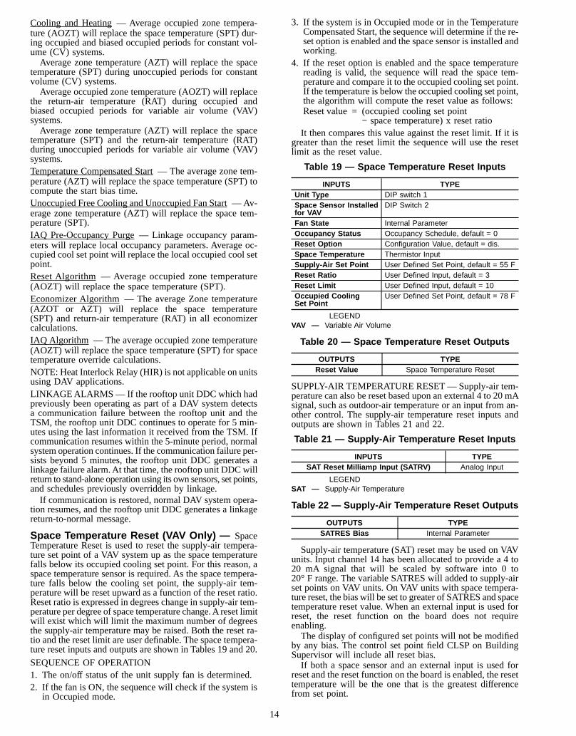
Space Temperature Reset (VAV Only) — SpaceTemperature Reset is used to reset the supply-air tempera-ture set point of a VAV system up as the space temperaturefalls below its occupied cooling set point. For this reason, aspace temperature sensor is required. As the space tempera-ture falls below the cooling set point, the supply-air tem-perature will be reset upward as a function of the reset ratio.Reset ratio is expressed in degrees change in supply-air tem-perature per degree of space temperature change.A reset limitwill exist which will limit the maximum number of degreesthe supply-air temperature may be raised. Both the reset ra-tio and the reset limit are user definable. The space tempera-ture reset inputs and outputs are shown in Tables 19 and 20.
SEQUENCE OF OPERATION1. The on/off status of the unit supply fan is determined.2. If the fan is ON, the sequence will check if the system is
in Occupied mode.
3. If the system is in Occupied mode or in the TemperatureCompensated Start, the sequence will determine if the re-set option is enabled and the space sensor is installed andworking.
4. If the reset option is enabled and the space temperaturereading is valid, the sequence will read the space tem-perature and compare it to the occupied cooling set point.If the temperature is below the occupied cooling set point,the algorithm will compute the reset value as follows:Reset value = (occupied cooling set point
− space temperature) x reset ratioIt then compares this value against the reset limit. If it is
greater than the reset limit the sequence will use the resetlimit as the reset value.
Table 19 — Space Temperature Reset Inputs
INPUTS TYPEUnit Type DIP switch 1Space Sensor Installedfor VAV
DIP Switch 2
Fan State Internal ParameterOccupancy Status Occupancy Schedule, default = 0Reset Option Configuration Value, default = dis.Space Temperature Thermistor InputSupply-Air Set Point User Defined Set Point, default = 55 FReset Ratio User Defined Input, default = 3Reset Limit User Defined Input, default = 10Occupied CoolingSet Point
User Defined Set Point, default = 78 F
LEGENDVAV — Variable Air Volume
Table 20 — Space Temperature Reset Outputs
OUTPUTS TYPEReset Value Space Temperature Reset
SUPPLY-AIR TEMPERATURE RESET— Supply-air tem-perature can also be reset based upon an external 4 to 20 mAsignal, such as outdoor-air temperature or an input from an-other control. The supply-air temperature reset inputs andoutputs are shown in Tables 21 and 22.
Table 21 — Supply-Air Temperature Reset Inputs
INPUTS TYPESAT Reset Milliamp Input (SATRV) Analog Input
LEGENDSAT — Supply-Air Temperature
Table 22 — Supply-Air Temperature Reset Outputs
OUTPUTS TYPESATRES Bias Internal Parameter
Supply-air temperature (SAT) reset may be used on VAVunits. Input channel 14 has been allocated to provide a 4 to20 mA signal that will be scaled by software into 0 to20° F range. The variable SATRES will added to supply-airset points on VAV units. On VAV units with space tempera-ture reset, the bias will be set to greater of SATRES and spacetemperature reset value. When an external input is used forreset, the reset function on the board does not requireenabling.The display of configured set points will not be modified
by any bias. The control set point field CLSP on BuildingSupervisor will include all reset bias.If both a space sensor and an external input is used for
reset and the reset function on the board is enabled, the resettemperature will be the one that is the greatest differencefrom set point.
14
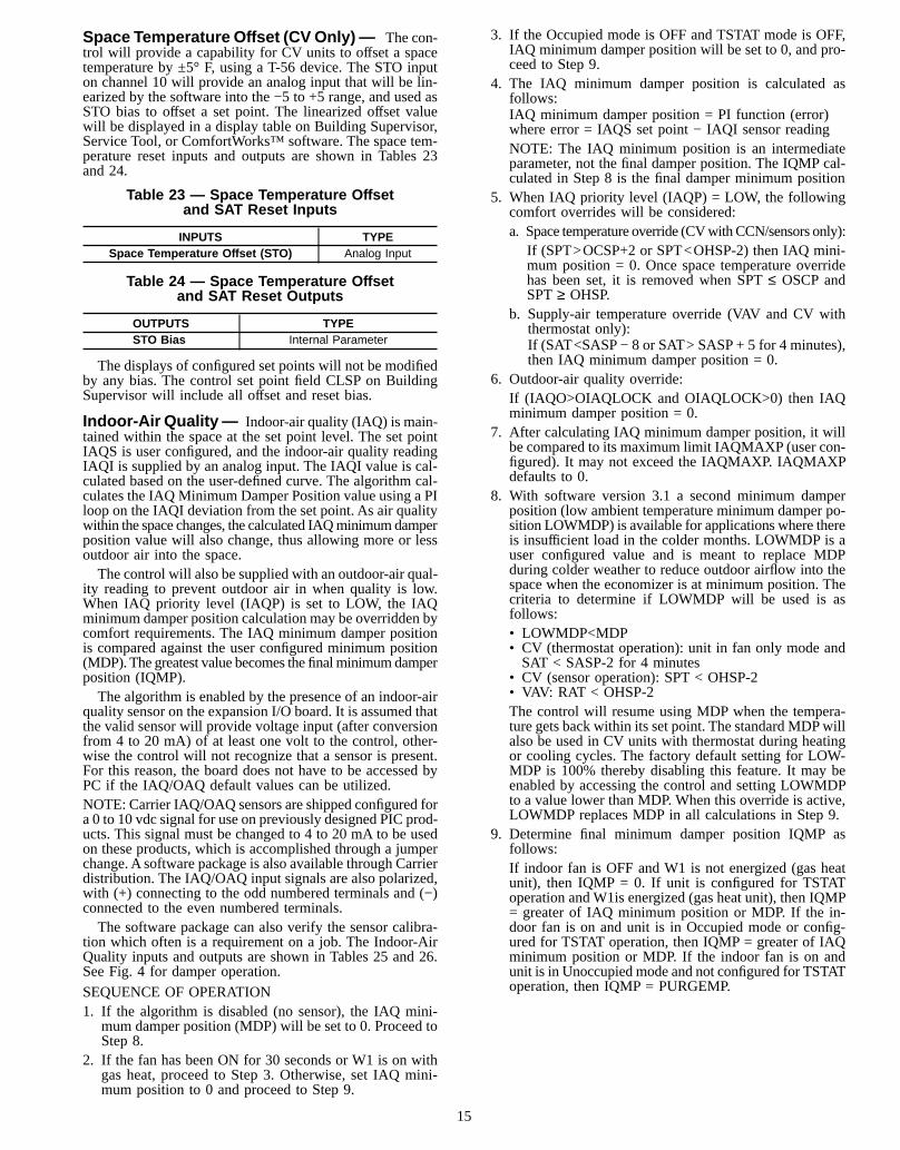
Space Temperature Offset (CVOnly)— The con-trol will provide a capability for CV units to offset a spacetemperature by ±5° F, using a T-56 device. The STO inputon channel 10 will provide an analog input that will be lin-earized by the software into the −5 to +5 range, and used asSTO bias to offset a set point. The linearized offset valuewill be displayed in a display table on Building Supervisor,Service Tool, or ComfortWorks™ software. The space tem-perature reset inputs and outputs are shown in Tables 23and 24.
Table 23 — Space Temperature Offsetand SAT Reset Inputs
INPUTS TYPESpace Temperature Offset (STO) Analog Input
Table 24 — Space Temperature Offsetand SAT Reset Outputs
OUTPUTS TYPESTO Bias Internal Parameter
The displays of configured set points will not be modifiedby any bias. The control set point field CLSP on BuildingSupervisor will include all offset and reset bias.
Indoor-Air Quality— Indoor-air quality (IAQ) is main-tained within the space at the set point level. The set pointIAQS is user configured, and the indoor-air quality readingIAQI is supplied by an analog input. The IAQI value is cal-culated based on the user-defined curve. The algorithm cal-culates the IAQ Minimum Damper Position value using a PIloop on the IAQI deviation from the set point. As air qualitywithin the space changes, the calculated IAQminimumdamperposition value will also change, thus allowing more or lessoutdoor air into the space.The control will also be supplied with an outdoor-air qual-
ity reading to prevent outdoor air in when quality is low.When IAQ priority level (IAQP) is set to LOW, the IAQminimum damper position calculation may be overridden bycomfort requirements. The IAQ minimum damper positionis compared against the user configured minimum position(MDP). The greatest value becomes the finalminimumdamperposition (IQMP).The algorithm is enabled by the presence of an indoor-air
quality sensor on the expansion I/O board. It is assumed thatthe valid sensor will provide voltage input (after conversionfrom 4 to 20 mA) of at least one volt to the control, other-wise the control will not recognize that a sensor is present.For this reason, the board does not have to be accessed byPC if the IAQ/OAQ default values can be utilized.NOTE: Carrier IAQ/OAQ sensors are shipped configured fora 0 to 10 vdc signal for use on previously designed PIC prod-ucts. This signal must be changed to 4 to 20 mA to be usedon these products, which is accomplished through a jumperchange. A software package is also available through Carrierdistribution. The IAQ/OAQ input signals are also polarized,with (+) connecting to the odd numbered terminals and (−)connected to the even numbered terminals.The software package can also verify the sensor calibra-
tion which often is a requirement on a job. The Indoor-AirQuality inputs and outputs are shown in Tables 25 and 26.See Fig. 4 for damper operation.
SEQUENCE OF OPERATION1. If the algorithm is disabled (no sensor), the IAQ mini-
mum damper position (MDP) will be set to 0. Proceed toStep 8.
2. If the fan has been ON for 30 seconds or W1 is on withgas heat, proceed to Step 3. Otherwise, set IAQ mini-mum position to 0 and proceed to Step 9.
3. If the Occupied mode is OFF and TSTAT mode is OFF,IAQ minimum damper position will be set to 0, and pro-ceed to Step 9.
4. The IAQ minimum damper position is calculated asfollows:IAQ minimum damper position = PI function (error)where error = IAQS set point − IAQI sensor readingNOTE: The IAQ minimum position is an intermediateparameter, not the final damper position. The IQMP cal-culated in Step 8 is the final damper minimum position
5. When IAQ priority level (IAQP) = LOW, the followingcomfort overrides will be considered:a. Space temperature override (CVwithCCN/sensors only):
If (SPT>OCSP+2 or SPT<OHSP-2) then IAQ mini-mum position = 0. Once space temperature overridehas been set, it is removed when SPT≤ OSCP andSPT≥ OHSP.
b. Supply-air temperature override (VAV and CV withthermostat only):If (SAT<SASP − 8 or SAT> SASP + 5 for 4 minutes),then IAQ minimum damper position = 0.
6. Outdoor-air quality override:If (IAQO>OIAQLOCK and OIAQLOCK>0) then IAQminimum damper position = 0.
7. After calculating IAQ minimum damper position, it willbe compared to its maximum limit IAQMAXP (user con-figured). It may not exceed the IAQMAXP. IAQMAXPdefaults to 0.
8. With software version 3.1 a second minimum damperposition (low ambient temperature minimum damper po-sition LOWMDP) is available for applications where thereis insufficient load in the colder months. LOWMDP is auser configured value and is meant to replace MDPduring colder weather to reduce outdoor airflow into thespace when the economizer is at minimum position. Thecriteria to determine if LOWMDP will be used is asfollows:• LOWMDP<MDP• CV (thermostat operation): unit in fan only mode andSAT < SASP-2 for 4 minutes
• CV (sensor operation): SPT < OHSP-2• VAV: RAT < OHSP-2The control will resume using MDP when the tempera-ture gets back within its set point. The standard MDPwillalso be used in CV units with thermostat during heatingor cooling cycles. The factory default setting for LOW-MDP is 100% thereby disabling this feature. It may beenabled by accessing the control and setting LOWMDPto a value lower than MDP. When this override is active,LOWMDP replaces MDP in all calculations in Step 9.
9. Determine final minimum damper position IQMP asfollows:If indoor fan is OFF and W1 is not energized (gas heatunit), then IQMP = 0. If unit is configured for TSTAToperation andW1is energized (gas heat unit), then IQMP= greater of IAQ minimum position or MDP. If the in-door fan is on and unit is in Occupied mode or config-ured for TSTAT operation, then IQMP = greater of IAQminimum position or MDP. If the indoor fan is on andunit is in Unoccupied mode and not configured for TSTAToperation, then IQMP = PURGEMP.
15
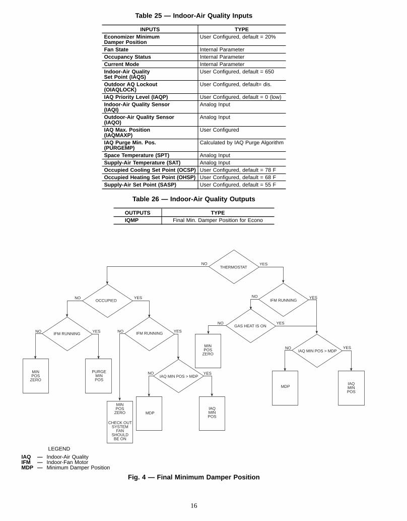
Table 25 — Indoor-Air Quality Inputs
INPUTS TYPEEconomizer MinimumDamper Position
User Configured, default = 20%
Fan State Internal ParameterOccupancy Status Internal ParameterCurrent Mode Internal ParameterIndoor-Air QualitySet Point (IAQS)
User Configured, default = 650
Outdoor AQ Lockout(OIAQLOCK)
User Configured, default= dis.
IAQ Priority Level (IAQP) User Configured, default = 0 (low)Indoor-Air Quality Sensor(IAQI)
Analog Input
Outdoor-Air Quality Sensor(IAQO)
Analog Input
IAQ Max. Position(IAQMAXP)
User Configured
IAQ Purge Min. Pos.(PURGEMP)
Calculated by IAQ Purge Algorithm
Space Temperature (SPT) Analog InputSupply-Air Temperature (SAT) Analog InputOccupied Cooling Set Point (OCSP) User Configured, default = 78 FOccupied Heating Set Point (OHSP) User Configured, default = 68 FSupply-Air Set Point (SASP) User Configured, default = 55 F
Table 26 — Indoor-Air Quality Outputs
OUTPUTS TYPEIQMP Final Min. Damper Position for Econo
IAQ MIN POS > MDPYES
IAQMINPOS
MINPOS
ZERO
MDP
MINPOS
ZERO
CHECK OUTSYSTEM
FANSHOULDBE ON
PURGEMINPOS
MINPOS
ZERO
NOIFM RUNNING
YES NO
NO
YES
NOGAS HEAT IS ON
YES
NO
IFM RUNNINGYES
IAQ MIN POS > MDP
NO
THERMOSTATYESNO
OCCUPIEDYES
IFM RUNNING
NO
MDPIAQMINPOS
YES
LEGEND
IAQ — Indoor-Air QualityIFM — Indoor-Fan MotorMDP — Minimum Damper Position
Fig. 4 — Final Minimum Damper Position
16
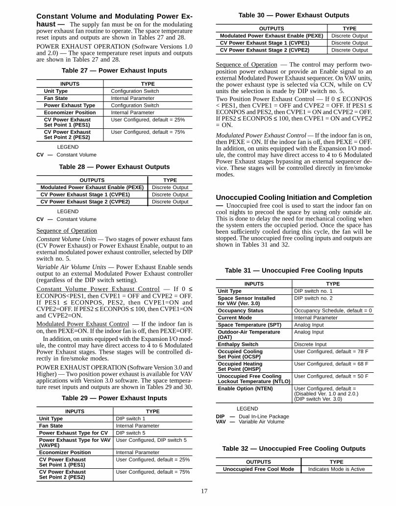
Constant Volume and Modulating Power Ex-haust — The supply fan must be on for the modulatingpower exhaust fan routine to operate. The space temperaturereset inputs and outputs are shown in Tables 27 and 28.
POWER EXHAUST OPERATION (Software Versions 1.0and 2.0) — The space temperature reset inputs and outputsare shown in Tables 27 and 28.
Table 27 — Power Exhaust Inputs
INPUTS TYPEUnit Type Configuration SwitchFan State Internal ParameterPower Exhaust Type Configuration SwitchEconomizer Position Internal ParameterCV Power ExhaustSet Point 1 (PES1)
User Configured, default = 25%
CV Power ExhaustSet Point 2 (PES2)
User Configured, default = 75%
LEGEND
CV — Constant Volume
Table 28 — Power Exhaust Outputs
OUTPUTS TYPEModulated Power Exhaust Enable (PEXE) Discrete OutputCV Power Exhaust Stage 1 (CVPE1) Discrete OutputCV Power Exhaust Stage 2 (CVPE2) Discrete Output
LEGEND
CV — Constant Volume
Sequence of OperationConstant Volume Units —Two stages of power exhaust fans(CV Power Exhaust) or Power Exhaust Enable, output to anexternal modulated power exhaust controller, selected by DIPswitch no. 5.Variable Air Volume Units —Power Exhaust Enable sendsoutput to an external Modulated Power Exhaust controller(regardless of the DIP switch setting).Constant Volume Power Exhaust Control — If 0≤ECONPOS<PES1, then CVPE1 = OFF and CVPE2 = OFF.If PES1 ≤ ECONPOS, PES2, then CVPE1=ON andCVPE2=OFF. If PES2≤ECONPOS≤ 100, then CVPE1=ONand CVPE2=ON.Modulated Power Exhaust Control — If the indoor fan ison, then PEXE=ON. If the indoor fan is off, then PEXE=OFF.In addition, on units equipped with the Expansion I/Omod-
ule, the control may have direct access to 4 to 6 ModulatedPower Exhaust stages. These stages will be controlled di-rectly in fire/smoke modes.
POWEREXHAUSTOPERATION (SoftwareVersion 3.0 andHigher) — Two position power exhaust is available for VAVapplications with Version 3.0 software. The space tempera-ture reset inputs and outputs are shown in Tables 29 and 30.
Table 29 — Power Exhaust Inputs
INPUTS TYPEUnit Type DIP switch 1Fan State Internal ParameterPower Exhaust Type for CV DIP switch 5Power Exhaust Type for VAV(VAVPE)
User Configured, DIP switch 5
Economizer Position Internal ParameterCV Power ExhaustSet Point 1 (PES1)
User Configured, default = 25%
CV Power ExhaustSet Point 2 (PES2)
User Configured, default = 75%
Table 30 — Power Exhaust Outputs
OUTPUTS TYPEModulated Power Exhaust Enable (PEXE) Discrete OutputCV Power Exhaust Stage 1 (CVPE1) Discrete OutputCV Power Exhaust Stage 2 (CVPE2) Discrete Output
Sequence of Operation — The control may perform two-position power exhaust or provide an Enable signal to anexternal Modulated Power Exhaust sequencer. On VAV units,the power exhaust type is selected via CCN, while on CVunits the selection is made by DIP switch no. 5.Two Position Power Exhaust Control — If 0≤ ECONPOS< PES1, then CVPE1 = OFF and CVPE2 = OFF. If PES1≤ECONPOS and PES2, then CVPE1 =ON and CVPE2 =OFF.If PES2≤ ECONPOS≤ 100, then CVPE1 = ON and CVPE2= ON.
Modulated Power Exhaust Control —If the indoor fan is on,then PEXE = ON. If the indoor fan is off, then PEXE = OFF.In addition, on units equipped with the Expansion I/O mod-ule, the control may have direct access to 4 to 6 ModulatedPower Exhaust stages bypassing an external sequencer de-vice. These stages will be controlled directly in fire/smokemodes.
Unoccupied Cooling Initiation and Completion— Unoccupied free cool is used to start the indoor fan oncool nights to precool the space by using only outside air.This is done to delay the need for mechanical cooling whenthe system enters the occupied period. Once the space hasbeen sufficiently cooled during this cycle, the fan will bestopped. The unoccupied free cooling inputs and outputs areshown in Tables 31 and 32.
Table 31 — Unoccupied Free Cooling Inputs
INPUTS TYPEUnit Type DIP switch no. 1Space Sensor Installedfor VAV (Ver. 3.0)
DIP switch no. 2
Occupancy Status Occupancy Schedule, default = 0Current Mode Internal ParameterSpace Temperature (SPT) Analog InputOutdoor-Air Temperature(OAT)
Analog Input
Enthalpy Switch Discrete InputOccupied CoolingSet Point (OCSP)
User Configured, default = 78 F
Occupied HeatingSet Point (OHSP)
User Configured, default = 68 F
Unoccupied Free CoolingLockout Temperature (NTLO)
User Configured, default = 50 F
Enable Option (NTEN) User Configured, default =(Disabled Ver. 1.0 and 2.0.)(DIP switch Ver. 3.0)
LEGEND
DIP — Dual In-Line PackageVAV — Variable Air Volume
Table 32 — Unoccupied Free Cooling Outputs
OUTPUTS TYPEUnoccupied Free Cool Mode Indicates Mode is Active
17
QUALIFYING CONDITIONS—The following conditionsmust be met for Unoccupied Free Cooling to be active:• NTEN option is enabled• Unit is in unoccupied state• Temperature Compensated Start mode is not active• Heat mode is not active• Space temperature (SPT) reading is available• Outdoor-air temperature (OAT) reading is available• Enthalpy is acceptable• OAT>NTLO (with 1 degree F hysteresis)
SEQUENCE OF OPERATION — If any of the qualifyingconditions are not met, Unoccupied free cool mode will notstart. Otherwise, the Unoccupied free cool mode will be con-trolled as follows:The Unoccupied free cool set point (NTSP) is determined
based on the unit type as follows:NTSP = OCSP for VAV unitsTSP = (OCSP + OHSP)/2 for CV units
The Unoccupied Free Cool mode will be started when:SPT >(NTSP + 2) and SPT >(OAT + 8)The Unoccupied Free Cool mode will be stopped when:SPT < NTSP or SPT < (OAT + 3)
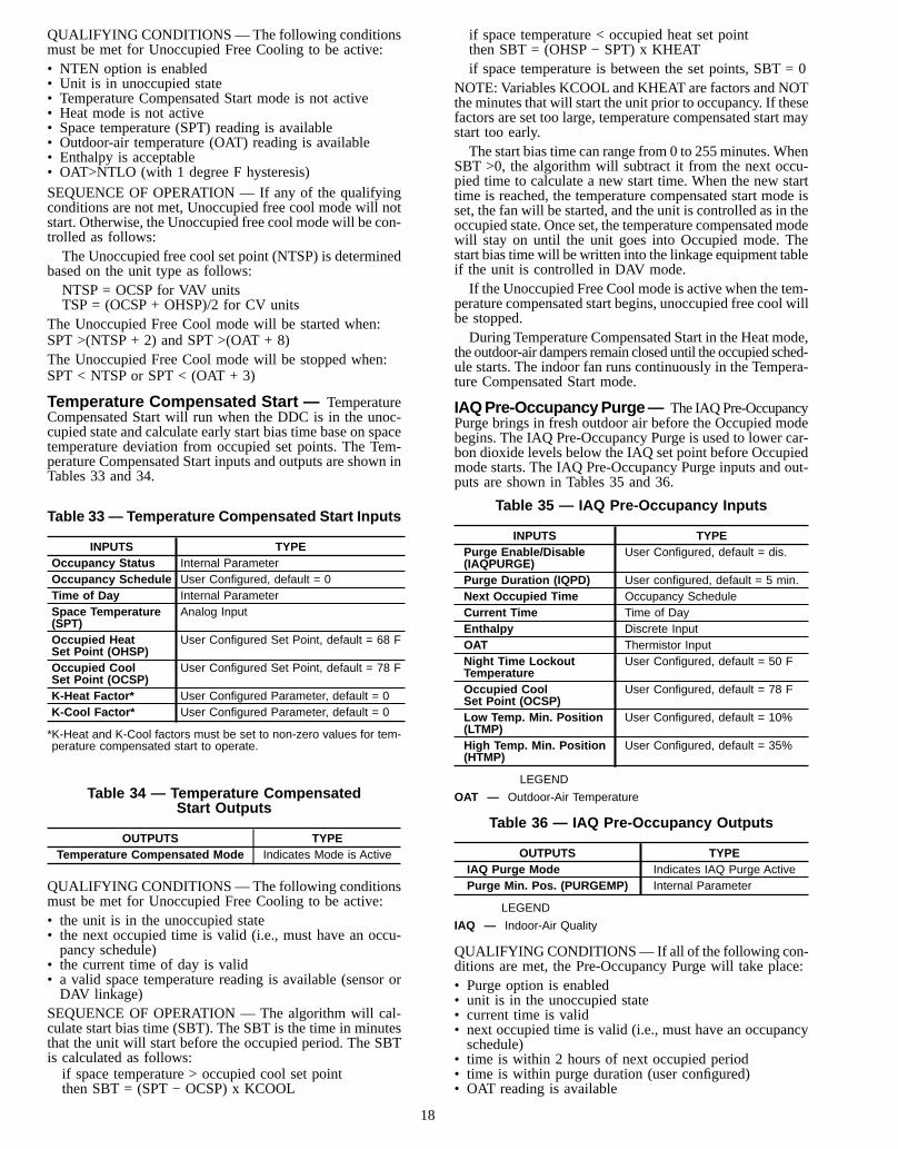
Temperature Compensated Start — TemperatureCompensated Start will run when the DDC is in the unoc-cupied state and calculate early start bias time base on spacetemperature deviation from occupied set points. The Tem-perature Compensated Start inputs and outputs are shown inTables 33 and 34.
Table 33 — Temperature Compensated Start Inputs
INPUTS TYPEOccupancy Status Internal ParameterOccupancy Schedule User Configured, default = 0Time of Day Internal ParameterSpace Temperature(SPT)
Analog Input
Occupied HeatSet Point (OHSP)
User Configured Set Point, default = 68 F
Occupied CoolSet Point (OCSP)
User Configured Set Point, default = 78 F
K-Heat Factor* User Configured Parameter, default = 0K-Cool Factor* User Configured Parameter, default = 0
*K-Heat and K-Cool factors must be set to non-zero values for tem-perature compensated start to operate.
Table 34 — Temperature CompensatedStart Outputs
OUTPUTS TYPETemperature Compensated Mode Indicates Mode is Active
QUALIFYING CONDITIONS—The following conditionsmust be met for Unoccupied Free Cooling to be active:• the unit is in the unoccupied state• the next occupied time is valid (i.e., must have an occu-pancy schedule)
• the current time of day is valid• a valid space temperature reading is available (sensor orDAV linkage)
SEQUENCE OF OPERATION — The algorithm will cal-culate start bias time (SBT). The SBT is the time in minutesthat the unit will start before the occupied period. The SBTis calculated as follows:if space temperature > occupied cool set pointthen SBT = (SPT − OCSP) x KCOOL
if space temperature < occupied heat set pointthen SBT = (OHSP − SPT) x KHEATif space temperature is between the set points, SBT = 0
NOTE: Variables KCOOL and KHEAT are factors and NOTthe minutes that will start the unit prior to occupancy. If thesefactors are set too large, temperature compensated start maystart too early.The start bias time can range from 0 to 255 minutes. When
SBT >0, the algorithm will subtract it from the next occu-pied time to calculate a new start time. When the new starttime is reached, the temperature compensated start mode isset, the fan will be started, and the unit is controlled as in theoccupied state. Once set, the temperature compensated modewill stay on until the unit goes into Occupied mode. Thestart bias time will be written into the linkage equipment tableif the unit is controlled in DAV mode.If the Unoccupied Free Cool mode is active when the tem-
perature compensated start begins, unoccupied free cool willbe stopped.During Temperature Compensated Start in the Heat mode,
the outdoor-air dampers remain closed until the occupied sched-ule starts. The indoor fan runs continuously in the Tempera-ture Compensated Start mode.
IAQPre-OccupancyPurge— The IAQPre-OccupancyPurge brings in fresh outdoor air before the Occupied modebegins. The IAQ Pre-Occupancy Purge is used to lower car-bon dioxide levels below the IAQ set point before Occupiedmode starts. The IAQ Pre-Occupancy Purge inputs and out-puts are shown in Tables 35 and 36.
Table 35 — IAQ Pre-Occupancy Inputs
INPUTS TYPEPurge Enable/Disable(IAQPURGE)
User Configured, default = dis.
Purge Duration (IQPD) User configured, default = 5 min.Next Occupied Time Occupancy ScheduleCurrent Time Time of DayEnthalpy Discrete InputOAT Thermistor InputNight Time LockoutTemperature
User Configured, default = 50 F
Occupied CoolSet Point (OCSP)
User Configured, default = 78 F
Low Temp. Min. Position(LTMP)
User Configured, default = 10%
High Temp. Min. Position(HTMP)
User Configured, default = 35%
LEGEND
OAT — Outdoor-Air Temperature
Table 36 — IAQ Pre-Occupancy Outputs
OUTPUTS TYPEIAQ Purge Mode Indicates IAQ Purge ActivePurge Min. Pos. (PURGEMP) Internal Parameter
LEGEND
IAQ — Indoor-Air Quality
QUALIFYINGCONDITIONS— If all of the following con-ditions are met, the Pre-Occupancy Purge will take place:• Purge option is enabled• unit is in the unoccupied state• current time is valid• next occupied time is valid (i.e., must have an occupancyschedule)
• time is within 2 hours of next occupied period• time is within purge duration (user configured)• OAT reading is available
18
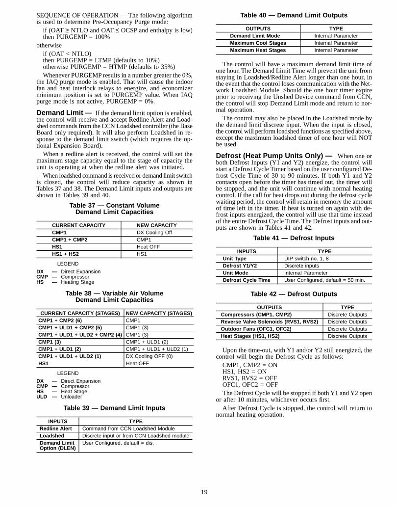
SEQUENCE OF OPERATION — The following algorithmis used to determine Pre-Occupancy Purge mode:if (OAT ≥ NTLO and OAT≤ OCSP and enthalpy is low)then PURGEMP = 100%
otherwiseif (OAT < NTLO)then PURGEMP = LTMP (defaults to 10%)otherwise PURGEMP = HTMP (defaults to 35%)Whenever PURGEMP results in a number greater the 0%,
the IAQ purge mode is enabled. That will cause the indoorfan and heat interlock relays to energize, and economizerminimum position is set to PURGEMP value. When IAQpurge mode is not active, PURGEMP = 0%.
Demand Limit — If the demand limit option is enabled,the control will receive and accept Redline Alert and Load-shed commands from the CCN Loadshed controller (the BaseBoard only required). It will also perform Loadshed in re-sponse to the demand limit switch (which requires the op-tional Expansion Board).When a redline alert is received, the control will set the
maximum stage capacity equal to the stage of capacity theunit is operating at when the redline alert was initiated.When loadshed command is received or demand limit switch
is closed, the control will reduce capacity as shown inTables 37 and 38. The Demand Limit inputs and outputs areshown in Tables 39 and 40.
Table 37 — Constant VolumeDemand Limit Capacities
CURRENT CAPACITY NEW CAPACITYCMP1 DX Cooling OffCMP1 + CMP2 CMP1HS1 Heat OFFHS1 + HS2 HS1
LEGEND
DX — Direct ExpansionCMP — CompressorHS — Heating Stage
Table 38 — Variable Air VolumeDemand Limit Capacities
CURRENT CAPACITY (STAGES) NEW CAPACITY (STAGES)CMP1 + CMP2 (6) CMP1CMP1 + ULD1 + CMP2 (5) CMP1 (3)CMP1 + ULD1 + ULD2 + CMP2 (4) CMP1 (3)CMP1 (3) CMP1 + ULD1 (2)CMP1 + ULD1 (2) CMP1 + ULD1 + ULD2 (1)CMP1 + ULD1 + ULD2 (1) DX Cooling OFF (0)HS1 Heat OFF
LEGEND
DX — Direct ExpansionCMP — CompressorHS — Heat StageULD — Unloader
Table 39 — Demand Limit Inputs
INPUTS TYPERedline Alert Command from CCN Loadshed ModuleLoadshed Discrete input or from CCN Loadshed moduleDemand LimitOption (DLEN)
User Configured, default = dis.
Table 40 — Demand Limit Outputs
OUTPUTS TYPEDemand Limit Mode Internal ParameterMaximum Cool Stages Internal ParameterMaximum Heat Stages Internal Parameter
The control will have a maximum demand limit time ofone hour. The Demand Limit Time will prevent the unit fromstaying in Loadshed/Redline Alert longer than one hour, inthe event that the control loses communication with the Net-work Loadshed Module. Should the one hour timer expireprior to receiving the Unshed Device command from CCN,the control will stop Demand Limit mode and return to nor-mal operation.The control may also be placed in the Loadshed mode by
the demand limit discrete input. When the input is closed,the control will perform loadshed functions as specified above,except the maximum loadshed timer of one hour will NOTbe used.
Defrost (Heat Pump Units Only) — When one orboth Defrost Inputs (Y1 and Y2) energize, the control willstart a Defrost Cycle Timer based on the user configured De-frost Cycle Time of 30 to 90 minutes. If both Y1 and Y2contacts open before the timer has timed out, the timer willbe stopped, and the unit will continue with normal heatingcontrol. If the call for heat drops out during the defrost cyclewaiting period, the control will retain in memory the amountof time left in the timer. If heat is turned on again with de-frost inputs energized, the control will use that time insteadof the entire Defrost Cycle Time. The Defrost inputs and out-puts are shown in Tables 41 and 42.
Table 41 — Defrost Inputs
INPUTS TYPEUnit Type DIP switch no. 1, 8Defrost Y1/Y2 Discrete inputsUnit Mode Internal ParameterDefrost Cycle Time User Configured, default = 50 min.
Table 42 — Defrost Outputs
OUTPUTS TYPECompressors (CMP1, CMP2) Discrete OutputsReverse Valve Solenoids (RVS1, RVS2) Discrete OutputsOutdoor Fans (OFC1, OFC2) Discrete OutputsHeat Stages (HS1, HS2) Discrete Outputs
Upon the time-out, with Y1 and/or Y2 still energized, thecontrol will begin the Defrost Cycle as follows:CMP1, CMP2 = ONHS1, HS2 = ONRVS1, RVS2 = OFFOFC1, OFC2 = OFFThe Defrost Cycle will be stopped if both Y1 andY2 open
or after 10 minutes, whichever occurs first.After Defrost Cycle is stopped, the control will return to
normal heating operation.
19
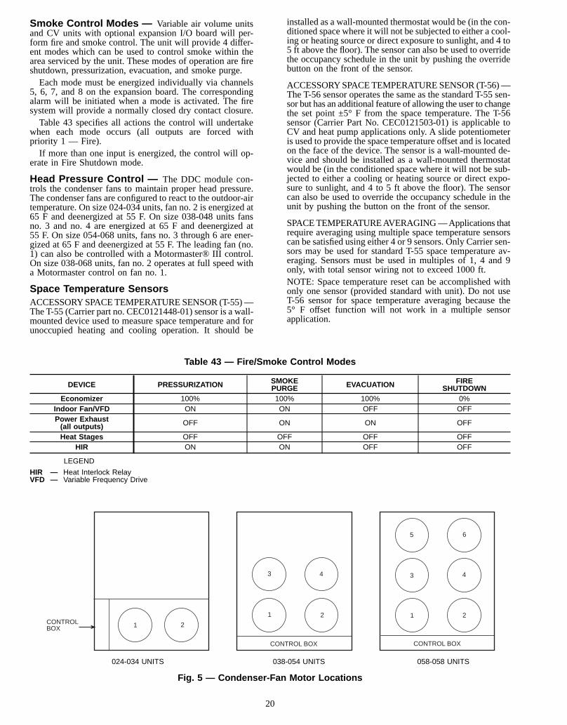
Smoke Control Modes — Variable air volume unitsand CV units with optional expansion I/O board will per-form fire and smoke control. The unit will provide 4 differ-ent modes which can be used to control smoke within thearea serviced by the unit. These modes of operation are fireshutdown, pressurization, evacuation, and smoke purge.Each mode must be energized individually via channels
5, 6, 7, and 8 on the expansion board. The correspondingalarm will be initiated when a mode is activated. The firesystem will provide a normally closed dry contact closure.Table 43 specifies all actions the control will undertake
when each mode occurs (all outputs are forced withpriority 1 — Fire).If more than one input is energized, the control will op-
erate in Fire Shutdown mode.
Head Pressure Control — The DDC module con-trols the condenser fans to maintain proper head pressure.The condenser fans are configured to react to the outdoor-airtemperature. On size 024-034 units, fan no. 2 is energized at65 F and deenergized at 55 F. On size 038-048 units fansno. 3 and no. 4 are energized at 65 F and deenergized at55 F. On size 054-068 units, fans no. 3 through 6 are ener-gized at 65 F and deenergized at 55 F. The leading fan (no.1) can also be controlled with a Motormaster® III control.On size 038-068 units, fan no. 2 operates at full speed witha Motormaster control on fan no. 1.
Space Temperature SensorsACCESSORYSPACETEMPERATURESENSOR (T-55)—The T-55 (Carrier part no. CEC0121448-01) sensor is a wall-mounted device used to measure space temperature and forunoccupied heating and cooling operation. It should be
installed as a wall-mounted thermostat would be (in the con-ditioned space where it will not be subjected to either a cool-ing or heating source or direct exposure to sunlight, and 4 to5 ft above the floor). The sensor can also be used to overridethe occupancy schedule in the unit by pushing the overridebutton on the front of the sensor.
ACCESSORYSPACETEMPERATURESENSOR (T-56)—The T-56 sensor operates the same as the standard T-55 sen-sor but has an additional feature of allowing the user to changethe set point ±5° F from the space temperature. The T-56sensor (Carrier Part No. CEC0121503-01) is applicable toCV and heat pump applications only. A slide potentiometeris used to provide the space temperature offset and is locatedon the face of the device. The sensor is a wall-mounted de-vice and should be installed as a wall-mounted thermostatwould be (in the conditioned space where it will not be sub-jected to either a cooling or heating source or direct expo-sure to sunlight, and 4 to 5 ft above the floor). The sensorcan also be used to override the occupancy schedule in theunit by pushing the button on the front of the sensor.
SPACETEMPERATUREAVERAGING—Applications thatrequire averaging using multiple space temperature sensorscan be satisfied using either 4 or 9 sensors. Only Carrier sen-sors may be used for standard T-55 space temperature av-eraging. Sensors must be used in multiples of 1, 4 and 9only, with total sensor wiring not to exceed 1000 ft.NOTE: Space temperature reset can be accomplished withonly one sensor (provided standard with unit). Do not useT-56 sensor for space temperature averaging because the5° F offset function will not work in a multiple sensorapplication.
Table 43 — Fire/Smoke Control Modes
DEVICE PRESSURIZATION SMOKEPURGE EVACUATION FIRE
SHUTDOWNEconomizer 100% 100% 100% 0%
Indoor Fan/VFD ON ON OFF OFFPower Exhaust(all outputs) OFF ON ON OFF
Heat Stages OFF OFF OFF OFFHIR ON ON OFF OFF
LEGEND
HIR — Heat Interlock RelayVFD — Variable Frequency Drive
1 2
1 2
3 4
1 2
3 4
5 6
CONTROLBOX
CONTROL BOX CONTROL BOX
024-034 UNITS 038-054 UNITS 058-058 UNITS
Fig. 5 — Condenser-Fan Motor Locations
20

Base and Expansion Board Modules— Table 44is a map of the type of input and output for each channel andcorresponding terminal for both the base module as well asthe expansion module. Tables 45, 46, 47, and 48 indicate thechannel functions for the CV, heat pump,VAV, and expan-sion board, respectively. Tables 49 and 50 show theDIPswitchassignments for the control board.
Field Test — The field test program is initiated by mov-ing DIP switch no. 4 to the ON position. The field testsequence will start. The first sequence will close the outdoor-air damper. The control allows 90 seconds for the damper toclose in case it is in the full open position. Next, the indoorfan contactor is energized and the outside air damper beginsto open to its default value of 20%and stays at that positionfor a short period of time. The outdoor-air damper will thenopen to its full open position and again stay at that positionfor a short period of time. Then the outdoor-air damper willthen close.If the unit is equipped with power exhaust, stage 1 will be
energized for 5 seconds. If the unit is configured for stagetwo of power exhaust, it will be energized for 5 seconds af-ter the first stage is deenergized.The next step will energize the first stage of heat for
30 seconds, after which time the second stage heat will beenergized for an additional 30 seconds. Heat is thendeenergized.The last step will run the Cooling mode. Outdoor fan
contactor no. 1 is energized. This is followed by each stageof cooling energized with a 10 second delay between stages.Next outdoor fan contactor no. 2 is energized for10 seconds.
The compressors will now deenergize followed by the out-door fan contactors and indoor fan contactors. If the unit isequipped with the Integrated Gas Control (IGC) board, theindoor fan will continue to operate for an additional 30 sec-onds after deenergizing the circuit.The field test is complete.
Factory Test (Software Version 1.0 Only) — Afactory test (with DIP switch no. 8) was used only with Ver-sion 1.0 software.
The Factory Test DIP switch should not be enabled inthe field.
The factory/operational test is manually executed using aPersonal Computer program that reads inputs and control out-puts via CCN communications. Before the test is run, theunit will be placed in Factory Test mode by turning DIPswitch no. 8 to the Test position. As the switch is put into thetest position, all outputs will be turned off. The DDC willnow be ready to receive test commands from CCN. Whenthe factory test mode is initiated, a one-hour timeout timerwill be started by the DDC to prevent the unit from remain-ing in that mode for more than one hour.The factory test mode will be turned off when switch8 is
switched off or when theone hour timer expires,which-ever comes first. The factory test has been eliminated in Soft-ware Version 2.0 and 3.0.
Table 44 — Input/Output Points
CHANNEL NO.(TERMINALS) INPUT TYPE OUTPUT TYPE CHANNEL NO.
(TERMINALS) INPUT TYPE OUTPUT TYPE
1 (T17-T25) 24 Volt — 18 (T28-T29) — 24 or 115 Volt2 (T18-T25) 24 Volt — 19 (T30-T29) — 24 or 115 Volt3 (T19-T25) 24 Volt — 20 (T31-T32) — 24 or 115 Volt4 (T20-T25) 24 Volt — 21 (T33-T32) — 24 or 115 Volt5 (T21-T25) 24 Volt — 22 (T34-T35) — 24 or 115 Volt6 (T22-T25) 24 Volt — 23 (T36-T35) — 24 or 115 Volt7 (T23-T25) 24 Volt — 24 (T37-T38) — 24 or 115 Volt8 (T24-T25) 24 Volt — 25 (T39-T38) — 24 or 115 Volt9 (T1-T2) 10K Resistor — 26 (K1, N.O.) — SAME AS K1, COM10 (T3-T4) 5 or 10K Resistor — (K1, N.C.) — SAME AS K1, COM11 (T5-T6) 5K Resistor — (K1, COM) 24, 115 or 230 Volt —12 (T7-T8) 5K Resistor — 27 (K2, N.O) — SAME AS K2, COM13 (T9-T10) Resistor (TBD) — (K2, N.C.) — SAME AS K2, COM14 (T11-T12) 4 - 20 mA — (K2, COM) 24, 115 or 230 Volt —15 (T13-T14) 4 - 20 mA — 28 (K3, N.O.) — SAME AS K3, COM16 (T15-T16) 4 - 20 mA — (K3, N.C.) — SAME AS K3, COM17 (T26-T27) — 4 - 20 mA (K3, COM) 24, 115 or 230 Volt —
NOTE: For terminals with a 4 to 20 mA signal, odd numbered terminals are (+), even terminals are (−).
21
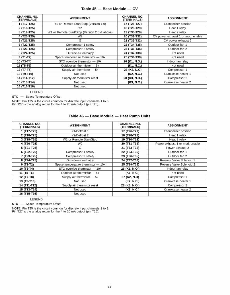
Table 45 — Base Module — CV
CHANNEL NO.(TERMINALS) ASSIGNMENT CHANNEL NO.
(TERMINALS) ASSIGNMENT
1 (T17-T25) Y1 or Remote Start/Stop (Version 1.0) 17 (T26-T27) Economizer position2 (T18-T25) Y2 18 (T28-T29) Heat 1 relay3 (T19-T25) W1 or Remote Start/Stop (Version 2.0 & above) 19 (T30-T29) Heat 2 relay4 (T20-T25) W2 20 (T31-T32) CV power exhaust 1 or mod. enable5 (T21-T25) G 21 (T33-T32) CV power exhaust 26 (T22-T25) Compressor 1 safety 22 (T34-T35) Outdoor fan 17 (T23-T25) Compressor 2 safety 23 (T36-T35) Outdoor fan 28 (T24-T25) Outside-air enthalpy 24 (T37-T38) Not used9 (T1-T2) Space temperature thermistor — 10k 25 (T39-T38) Not used10 (T3-T4) STO override thermistor — 10k 26 (K1, N.O.) Indoor fan relay11 (T5-T6) Outdoor-air thermistor — 5k (K1, N.C.) Not used12 (T7-T8) Supply-air thermistor — 5k 27 (K2, N.O) Compressor 113 (T9-T10) Not used (K2, N.C.) Crankcase heater 114 (T11-T12) Supply-air thermistor reset 28 (K3, N.O.) Compressor 215 (T13-T14) Not used (K3, N.C.) Crankcase heater 216 (T15-T16) Not used
LEGEND
STO — Space Temperature Offset
NOTE: Pin T25 is the circuit common for discrete input channels 1 to 8.Pin T27 is the analog return for the 4 to 20 mA output (pin T26).
Table 46 — Base Module — Heat Pump Units
CHANNEL NO.(TERMINALS) ASSIGNMENT CHANNEL NO.
(TERMINALS) ASSIGNMENT
1 (T17-T25) Y1/Defrost 1 17 (T26-T27) Economizer position2 (T18-T25) Y2/Defrost 2 18 (T28-T29) Heat 1 relay3 (T19-T25) W1 or Remote Start/Stop 19 (T30-T29) Heat 2 relay4 (T20-T25) W2 20 (T31-T32) Power exhaust 1 or mod. enable5 (T21-T25) G 21 (T33-T32) Power exhaust 26 (T22-T25) Compressor 1 safety 22 (T34-T35) Outdoor fan 17 (T23-T25) Compressor 2 safety 23 (T36-T35) Outdoor fan 28 (T24-T25) Outside-air enthalpy 24 (T37-T38) Reverse Valve Solenoid 19 (T1-T2) Space temperature thermistor — 10k 25 (T39-T38) Reverse Valve Solenoid 210 (T3-T4) STO override thermistor — 10k 26 (K1, N.O.) Indoor fan relay11 (T5-T6) Outdoor-air thermistor — 5k (K1, N.C.) Not used12 (T7-T8) Supply-air thermistor — 5k 27 (K2, N.O) Compressor 113 (T9-T10) Not used (K2, N.C.) Crankcase heater 114 (T11-T12) Supply-air thermistor reset 28 (K3, N.O.) Compressor 215 (T13-T14) Not used (K3, N.C.) Crankcase heater 216 (T15-T16) Not used
LEGEND
STO — Space Temperature Offset
NOTE: Pin T25 is the circuit common for discrete input channels 1 to 8.Pin T27 is the analog return for the 4 to 20 mA output (pin T26).
22
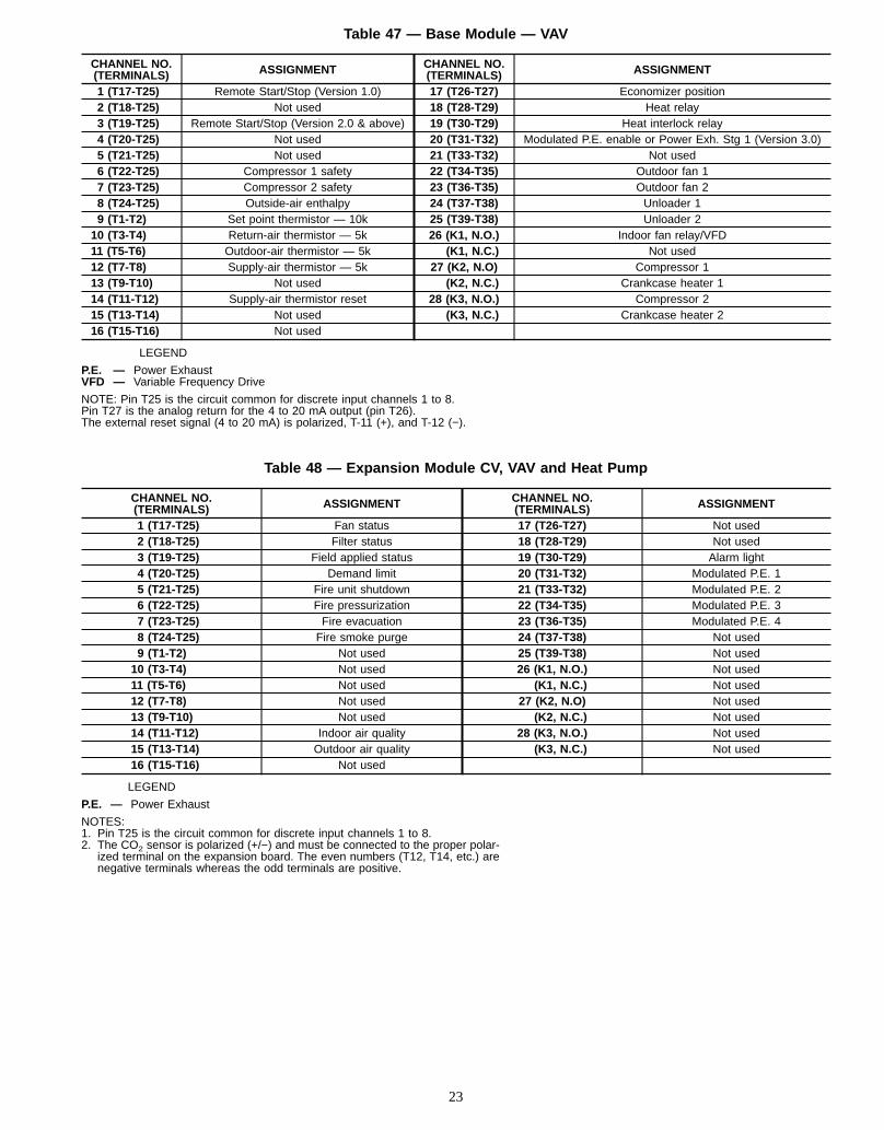
Table 47 — Base Module — VAV
CHANNEL NO.(TERMINALS) ASSIGNMENT CHANNEL NO.
(TERMINALS) ASSIGNMENT
1 (T17-T25) Remote Start/Stop (Version 1.0) 17 (T26-T27) Economizer position2 (T18-T25) Not used 18 (T28-T29) Heat relay3 (T19-T25) Remote Start/Stop (Version 2.0 & above) 19 (T30-T29) Heat interlock relay4 (T20-T25) Not used 20 (T31-T32) Modulated P.E. enable or Power Exh. Stg 1 (Version 3.0)5 (T21-T25) Not used 21 (T33-T32) Not used6 (T22-T25) Compressor 1 safety 22 (T34-T35) Outdoor fan 17 (T23-T25) Compressor 2 safety 23 (T36-T35) Outdoor fan 28 (T24-T25) Outside-air enthalpy 24 (T37-T38) Unloader 19 (T1-T2) Set point thermistor — 10k 25 (T39-T38) Unloader 210 (T3-T4) Return-air thermistor — 5k 26 (K1, N.O.) Indoor fan relay/VFD11 (T5-T6) Outdoor-air thermistor — 5k (K1, N.C.) Not used12 (T7-T8) Supply-air thermistor — 5k 27 (K2, N.O) Compressor 113 (T9-T10) Not used (K2, N.C.) Crankcase heater 114 (T11-T12) Supply-air thermistor reset 28 (K3, N.O.) Compressor 215 (T13-T14) Not used (K3, N.C.) Crankcase heater 216 (T15-T16) Not used
LEGEND
P.E. — Power ExhaustVFD — Variable Frequency Drive
NOTE: Pin T25 is the circuit common for discrete input channels 1 to 8.Pin T27 is the analog return for the 4 to 20 mA output (pin T26).The external reset signal (4 to 20 mA) is polarized, T-11 (+), and T-12 (−).
Table 48 — Expansion Module CV, VAV and Heat Pump
CHANNEL NO.(TERMINALS) ASSIGNMENT CHANNEL NO.
(TERMINALS) ASSIGNMENT
1 (T17-T25) Fan status 17 (T26-T27) Not used2 (T18-T25) Filter status 18 (T28-T29) Not used3 (T19-T25) Field applied status 19 (T30-T29) Alarm light4 (T20-T25) Demand limit 20 (T31-T32) Modulated P.E. 15 (T21-T25) Fire unit shutdown 21 (T33-T32) Modulated P.E. 26 (T22-T25) Fire pressurization 22 (T34-T35) Modulated P.E. 37 (T23-T25) Fire evacuation 23 (T36-T35) Modulated P.E. 48 (T24-T25) Fire smoke purge 24 (T37-T38) Not used9 (T1-T2) Not used 25 (T39-T38) Not used10 (T3-T4) Not used 26 (K1, N.O.) Not used11 (T5-T6) Not used (K1, N.C.) Not used12 (T7-T8) Not used 27 (K2, N.O) Not used13 (T9-T10) Not used (K2, N.C.) Not used14 (T11-T12) Indoor air quality 28 (K3, N.O.) Not used15 (T13-T14) Outdoor air quality (K3, N.C.) Not used16 (T15-T16) Not used
LEGEND
P.E. — Power Exhaust
NOTES:1. Pin T25 is the circuit common for discrete input channels 1 to 8.2. The CO2 sensor is polarized (+/−) and must be connected to the proper polar-
ized terminal on the expansion board. The even numbers (T12, T14, etc.) arenegative terminals whereas the odd terminals are positive.
23
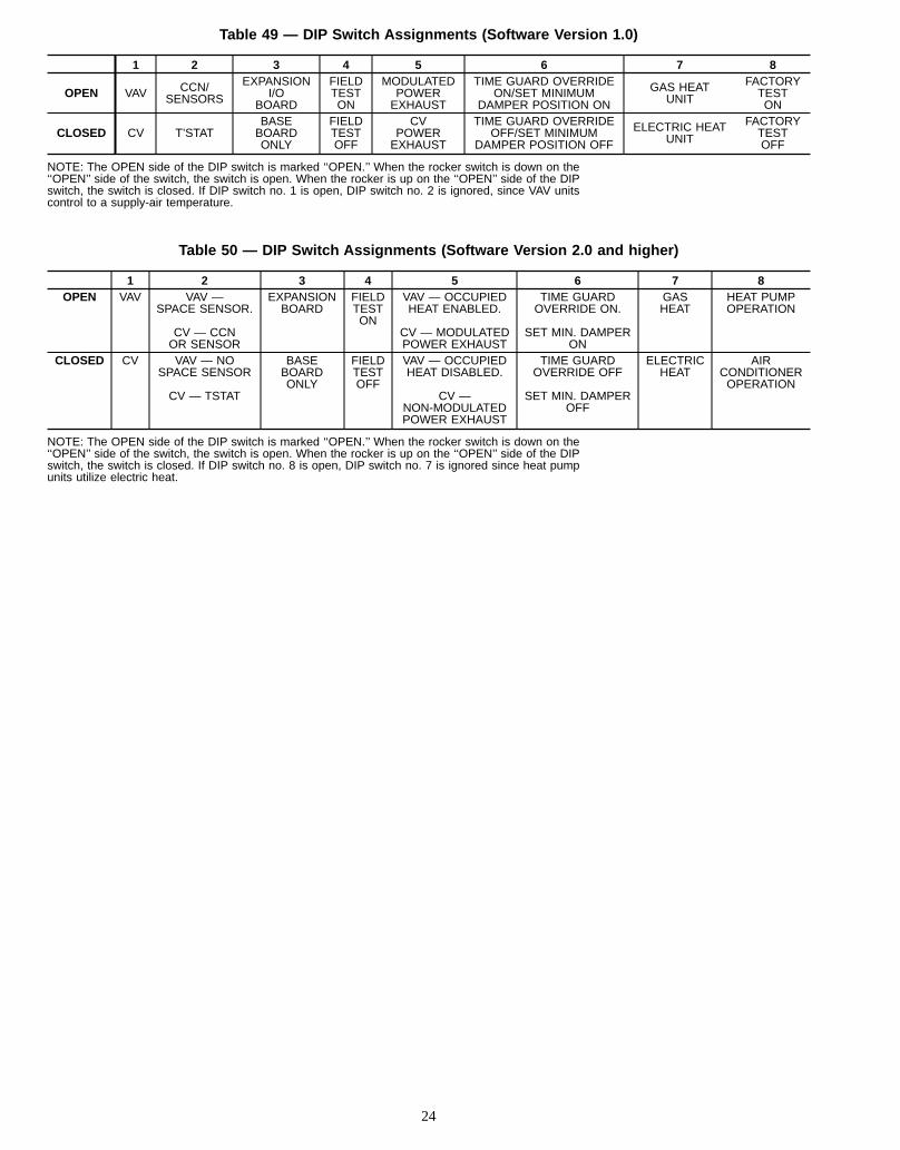
Table 49 — DIP Switch Assignments (Software Version 1.0)
1 2 3 4 5 6 7 8
OPEN VAV CCN/SENSORS
EXPANSIONI/O
BOARD
FIELDTESTON
MODULATEDPOWEREXHAUST
TIME GUARD OVERRIDEON/SET MINIMUM
DAMPER POSITION ON
GAS HEATUNIT
FACTORYTESTON
CLOSED CV T’STATBASEBOARDONLY
FIELDTESTOFF
CVPOWEREXHAUST
TIME GUARD OVERRIDEOFF/SET MINIMUM
DAMPER POSITION OFF
ELECTRIC HEATUNIT
FACTORYTESTOFF
NOTE: The OPEN side of the DIP switch is marked ‘‘OPEN.’’ When the rocker switch is down on the‘‘OPEN’’ side of the switch, the switch is open. When the rocker is up on the ‘‘OPEN’’ side of the DIPswitch, the switch is closed. If DIP switch no. 1 is open, DIP switch no. 2 is ignored, since VAV unitscontrol to a supply-air temperature.
Table 50 — DIP Switch Assignments (Software Version 2.0 and higher)
1 2 3 4 5 6 7 8OPEN VAV VAV —
SPACE SENSOR.
CV — CCNOR SENSOR
EXPANSIONBOARD
FIELDTESTON
VAV — OCCUPIEDHEAT ENABLED.
CV — MODULATEDPOWER EXHAUST
TIME GUARDOVERRIDE ON.
SET MIN. DAMPERON
GASHEAT
HEAT PUMPOPERATION
CLOSED CV VAV — NOSPACE SENSOR
CV — TSTAT
BASEBOARDONLY
FIELDTESTOFF
VAV — OCCUPIEDHEAT DISABLED.
CV —NON-MODULATEDPOWER EXHAUST
TIME GUARDOVERRIDE OFF
SET MIN. DAMPEROFF
ELECTRICHEAT
AIRCONDITIONEROPERATION
NOTE: The OPEN side of the DIP switch is marked ‘‘OPEN.’’ When the rocker switch is down on the‘‘OPEN’’ side of the switch, the switch is open. When the rocker is up on the ‘‘OPEN’’ side of the DIPswitch, the switch is closed. If DIP switch no. 8 is open, DIP switch no. 7 is ignored since heat pumpunits utilize electric heat.
24
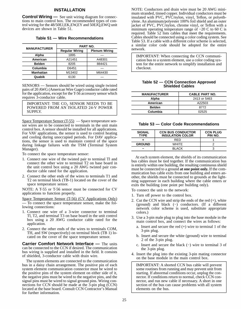
INSTALLATION
Control Wiring — See unit wiring diagram for connec-tions to main control box. The recommended types of con-trol wiring for the 48/50EJ,EK,EW,EYand 50EJQ,EWQ unitdevices are shown in Table 51.
Table 51 — Wire Recommendations
MANUFACTURERPART NO.
Regular Wiring Plenum WiringAlpha 1895 —
American A21451 A48301Belden 8205 884421
Columbia D6451 —Manhattan M13402 M64430Quabik 6130 —
SENSORS — Sensors should be wired using single twistedpairs of 20AWG (AmericanWire Gage) conductor cable ratedfor the application, except for the T-56 accessory sensor whichrequires 3-conductor cable.
IMPORTANT: THE CO2 SENSOR NEEDS TO BEPOWERED FROM AN ISOLATED 24-V POWERSUPPLY.
Space Temperature Sensor (T-55) —Space temperature sen-sor wires are to be connected to terminals in the unit maincontrol box. A sensor should be installed for all applications.For VAV applications, the sensor is used to control heatingand cooling during unoccupied periods. For DAV applica-tions, the sensor is used to maintain control of the spaceduring linkage failures with the TSM (Terminal SystemManager).To connect the space temperature sensor:1. Connect one wire of the twisted pair to terminal Tl and
connect the other wire to terminal T2 on base board inthe unit control box using a 20 AWG twisted pair con-ductor cable rated for the application.
2. Connect the other ends of the wires to terminals T1 andT2 on terminal block (TB-1) located on the cover of thespace temperature sensor.
NOTE: A T-55 or T-56 sensor must be connected for CVapplications to function properly.Space Temperature Sensor (T-56) (CV Applications Only)— To connect the space temperature sensor, make the fol-lowing connections:1. Connect one wire of a 3-wire connector to terminal
Tl, T2, and terminal T3 on base board in the unit controlbox using a 20 AWG conductor cable rated for theapplication.
2. Connect the other ends of the wires to terminals COM,TH, and SW (respectively) on terminal block (TB 1) lo-cated on the cover of the space temperature sensor.
Carrier Comfort Network Interface — The unitscan be connected to the CCN if desired. The communicationbus wiring is supplied and installed in the field. It consistsof shielded, 3-conductor cable with drain wire.The system elements are connected to the communication
bus in a daisy chain arrangement. The positive pin of eachsystem element communication connector must be wired tothe positive pins of the system element on either side of it,the negative pins must be wired to the negative pins, and thesignal pins must be wired to signal ground pins. Wiring con-nections for CCN should be made at the 3-pin plug (CCN)located at the base board. Consult CCN Contractor’s Manualfor further information.
NOTE: Conductors and drain wire must be 20 AWG mini-mum stranded, tinned copper. Individual conductors must beinsulated with PVC, PVC/nylon, vinyl, Teflon, or polyeth-ylene. An aluminum/polyester 100% foil shield and an outerjacket of PVC, PVC/nylon, chrome vinyl, or Teflon with aminimum operating temperature range of −20 C to 60 C isrequired. Table 52 lists cables that meet the requirements.Cables should be connected using a color coding system. SeeTable 53. If a cable with a different color scheme is selected,a similar color code should be adopted for the entirenetwork.
IMPORTANT: When connecting the CCN communi-cation bus to a system element, use a color coding sys-tem for the entire network to simplify installation andcheckout.
Table 52 — CCN Connection ApprovedShielded Cables
MANUFACTURER CABLE PART NO.Alpha 2413 or 5463
American A22503Belden 8772
Columbia 02525
Table 53 — Color Code Recommendations
SIGNALTYPE
CCN BUS CONDUCTORINSULATION COLOR
CCN PLUGPIN NO.
+ RED 1GROUND WHITE 2
− BLACK 3
At each system element, the shields of its communicationbus cables must be tied together. If the communication busis entirely within one building, the resulting continuous shieldmust be connected to a groundat one point only.If the com-munication bus cable exits from one building and enters an-other, the shields must be connected to grounds at the light-ning suppresser in each building where the cable enters orexits the building (one point per building only).To connect the unit to the network:1. Turn off power to the control box.2. Cut the CCN wire and strip the ends of the red (+), white
(ground) and black (−) conductors. (If a differentnetwork color scheme is used, substitute appropriatecolors.)
3. Use a 3-pin male plug to plug into the base module in themain control box, and connect the wires as follows:a. Insert and secure the red (+) wire to terminal 1 of the
3-pin plug.b. Insert and secure the white (ground) wire to terminal
2 of the 3-pin plug.c. Insert and secure the black (−) wire to terminal 3 of
the 3-pin plug.4. Insert the plug into the existing 3-pin mating connector
on the base module in the main control box.
IMPORTANT: A shorted CCN bus cable will preventsome routines from running and may prevent unit fromstarting. If abnormal conditions occur, unplug the con-nector. If conditions return to normal, check CCN con-nector, and run new cable if necessary. A short in onesection of the bus can cause problems with all systemelements on the bus.
25
RJ11 PLUG WIRING — Units on the CCN can be moni-tored from the space at the sensor through the RJ11 con-nector, if desired. To wire the RJ11 connector into the CCN:
IMPORTANT: The cable selected for the RJ11 con-nector wiring MUST be identical to the CCN commu-nication bus wire used for the entire network. Refer toTable 52 for acceptable wiring.
1. Cut the CCN wire and strip ends of the red (+), white(ground), and black (−) conductors. (If another wire colorscheme is used, strip ends of appropriate wires.)
2. Insert and secure the red (+) wire to pin J2 of the spacetemperature sensor terminal block (TB1).
3. Insert and secure the white (ground) wire to pin J3 of thespace temperature sensor TB1.
4. Insert and secure the black (−) wire to pin J5 of the spacetemperature sensor TB1.
5. Connect the other end of the communication bus cable tothe remainder of the CCN communication bus at the CCNplug located on base module in the unit main control box.
NOTE: The Base Module Address is BUS 0 (Zero),ELEMENT 1 (One).
Optional SmokeControl— When the unit is equippedwith an optional smoke control and a fire system is installed,4 modes are provided to control smoke within areas servicedby the rooftop unit. Each mode must be energized individu-ally from the approved building fire alarm system, and thecorresponding alarm is then generated at the base moduleLED (light-emitting diode) and/or Building Supervisor.
IMPORTANT: The unit MUST be equipped with a fac-tory installed economizer, the optional expansion mod-ule, and the optional factory-installed power exhaustto provide smoke control capabilities.
The building fire alarm system must provide 4 normallyopen dry contact closures. These contacts must be wired be-tween T21 - T25 (Fire Shutdown), T22 - T25 (Fire Pressur-ization), T23 - T25 (Fire Evacuation) and T24 - T25 (FireSmoke Purge) on the expansion module. Refer to the unitwiring diagram for the corresponding connection points.
FIRE SHUTDOWN MODE — The fire alarm system mustprovide a normally open dry contact closure which ener-gizes the Fire Shutdownmode when activated.When the FireShutdown mode is energized, the unit shuts down.This mode remains in effect as long as the input signal is
maintained at the fire system panel. An alarm is generatedfrom this input and sent to the Building Supervisor device.In order for this mode to be initiated, the input signal mustbe maintained for no less than 2 seconds.
EVACUATION MODE — The building fire alarm systemmust provide a normally open dry contact closure which en-ergizes the Evacuationmodewhen activated.When the Evacu-ation mode is energized, the supply-air fan will shut down,power exhaust fans will start, the outside-air damper will open,and the return-air damper will close.This mode remains in effect for as long as the input signal
is maintained at the fire system panel. An alarm is generatedfrom this input and sent to the Building Supervisor device.In order for this mode to be initiated, the input signal mustbe maintained for no less than 2 seconds.
PRESSURIZATION MODE— The building fire alarm sys-temmust provide a normally open dry contact closure whichenergizes the Pressurization mode when activated.When thePressurization mode is energized, the supply-air fan will start,the power exhaust fans will shut down, the outside-air damperwill open, and the power exhaust will be off.This mode remains in effect as long as the input signal is
maintained at the fire system panel. An alarm is generatedfrom this input and sent to the Building Supervisor device.In order for this mode to be initiated, the input signal mustbe maintained for no less than 2 seconds.
SMOKE PURGE MODE— The building fire alarm systemmust provide a normally open dry contact closure which en-ergizes the Smoke Purge mode when activated.When the Smoke Purge mode is energized, the supply and
power exhaust fans will start, the outdoor-air damper willopen, and the return-air damper will close.This mode remains in effect as long as the input signal is
maintained at the arm is generated from this input and sentto the Building fire system panel. An alarm is generated fromthis input and sent to the Building Supervisor device. In or-der for this mode to be initiated, the input signal must bemaintained for no less than 2 seconds.
Remote On/Off Control— The Remote ON/OFF con-trol is used in applications where it is necessary to start theunit from a remote clock or switch. The Remote ON/OFFcontrol can only stop a unit in the Unoccupied mode. It can-not stop a unit in the Occupied mode. If there is an occu-pancy schedule, a remote ON signal will put the board intooccupancy if it is in the Unoccupied mode.The Remote ON/OFF control is wired with a contact clo-
sure between terminal R and Y1 on TB-3 (Version 1.0 soft-ware) or between R and W1 on TB-3 (Version 2.0 and 3.0software).
Variable Frequency Drive — The variable fre-quency drives for the units are factory set. These settingsinclude factory-installed jumpers and software configura-tions. The exception is the duct static pressure set point. Theduct static pressure set point should be field-configured de-pending on the application. The factory setting is 30.These instructions are for Carrier Part No. HK30AA001
through 021 variable frequency drives. An OperationManual is shipped with each VAV unit. This manual shouldbe used if the drive needs to be customized for a particularapplication.Prior to unit serial number 0897F, all VAV units were built
with a duct pressure transducer with a 2 to 10 vdcsignalfeedback to the variable frequency drive. Starting with serialnumber 0897F all units from the factory were equipped witha transducer with a 4 to 20 mAsignal. A 4 to 20 milliampsignal is more reliable than a 2 to 10 vdcsignal.This improvement results in a change to the wiring of the
variable frequency drive on the terminal strip within the drive.See Fig. 6 and 7. Also, on the VFD printed circuit board, theJP1 jumper should be set to ‘‘V’’ for a 2 to 10 vdctransducerand ‘‘I’’ for a 4 to 20 mA transducer. See Fig. 8.
26
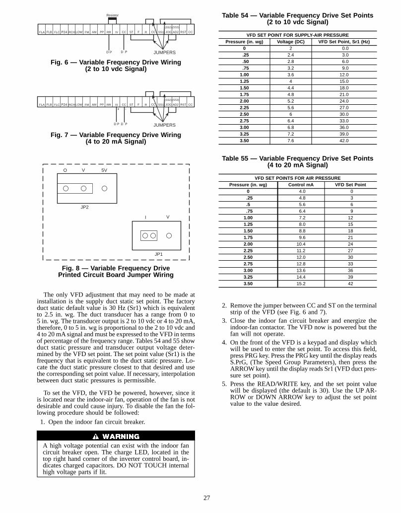
The only VFD adjustment that may need to be made atinstallation is the supply duct static set point. The factoryduct static default value is 30 Hz (Sr1) which is equivalentto 2.5 in. wg. The duct transducer has a range from 0 to5 in. wg. The transducer output is 2 to 10 vdc or 4 to 20 mA,therefore, 0 to 5 in. wg is proportional to the 2 to 10 vdc and4 to 20 mAsignal and must be expressed to the VFD in termsof percentage of the frequency range. Tables 54 and 55 showduct static pressure and transducer output voltage deter-mined by the VFD set point. The set point value (Sr1) is thefrequency that is equivalent to the duct static pressure. Lo-cate the duct static pressure closest to that desired and usethe corresponding set point value. If necessary, interpolationbetween duct static pressures is permissible.
To set the VFD, the VFD be powered, however, since itis located near the indoor-air fan, operation of the fan is notdesirable and could cause injury. To disable the fan the fol-lowing procedure should be followed:
1. Open the indoor fan circuit breaker.
A high voltage potential can exist with the indoor fancircuit breaker open. The charge LED, located in thetop right hand corner of the inverter control board, in-dicates charged capacitors. DO NOT TOUCH internalhigh voltage parts if lit.
Table 54 — Variable Frequency Drive Set Points(2 to 10 vdc Signal)
VFD SET POINT FOR SUPPLY-AIR PRESSUREPressure (in. wg) Voltage (DC) VFD Set Point, Sr1 (Hz)
0 2 0.0.25 2.4 3.0.50 2.8 6.0.75 3.2 9.01.00 3.6 12.01.25 4 15.01.50 4.4 18.01.75 4.8 21.02.00 5.2 24.02.25 5.6 27.02.50 6 30.02.75 6.4 33.03.00 6.8 36.03.25 7.2 39.03.50 7.6 42.0
Table 55 — Variable Frequency Drive Set Points(4 to 20 mA Signal)
VFD SET POINTS FOR AIR PRESSUREPressure (in. wg) Control mA VFD Set Point
0 4.0 0.25 4.8 3.5 5.6 6.75 6.4 91.00 7.2 121.25 8.0 151.50 8.8 181.75 9.6 212.00 10.4 242.25 11.2 272.50 12.0 302.75 12.8 333.00 13.6 363.25 14.4 393.50 15.2 42
2. Remove the jumper between CC and ST on the terminalstrip of the VFD (see Fig. 6 and 7).
3. Close the indoor fan circuit breaker and energize theindoor-fan contactor. The VFD now is powered but thefan will not operate.
4. On the front of the VFD is a keypad and display whichwill be used to enter the set point. To access this field,press PRG key. Press the PRG key until the display readsS.PrG, (The Speed Group Parameters), then press theARROWkey until the display reads Sr1 (VFD duct pres-sure set point).
5. Press the READ/WRITE key, and the set point valuewill be displayed (the default is 30). Use the UP AR-ROW or DOWN ARROW key to adjust the set pointvalue to the value desired.
P24FLA FLB FLC AM PP RR IV CC ST F R CC SS1 JOG AD2 RST CC
(SS2) (SS3)
JUMPERSD P D P
Resistor
RCH LOW FM
Fig. 6 — Variable Frequency Drive Wiring(2 to 10 vdc Signal)
P24FLA FLB FLC AM PP RR IV CC ST F R CC SS1 JOG AD2 RST CC
(SS2) (SS3)
JUMPERSD P D P
RCH LOW FM+ -
Fig. 7 — Variable Frequency Drive Wiring(4 to 20 mA Signal)
O V 5V
I V
JP2
JP1
Fig. 8 — Variable Frequency DrivePrinted Circuit Board Jumper Wiring
27
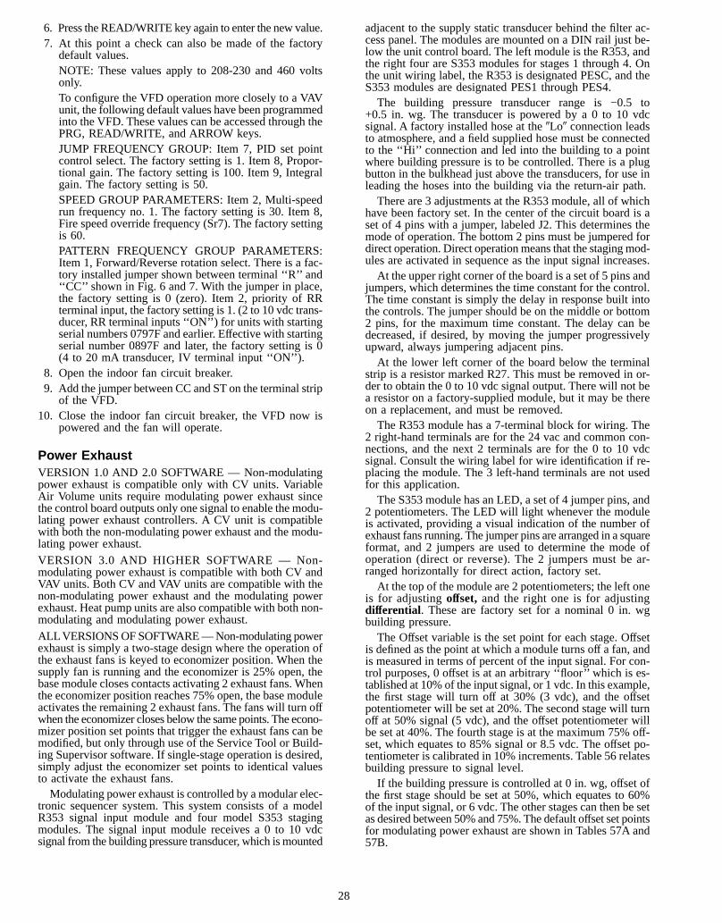
6. Press theREAD/WRITE key again to enter the new value.7. At this point a check can also be made of the factory
default values.NOTE: These values apply to 208-230 and 460 voltsonly.To configure the VFD operation more closely to a VAVunit, the following default values have been programmedinto the VFD. These values can be accessed through thePRG, READ/WRITE, and ARROW keys.JUMP FREQUENCY GROUP: Item 7, PID set pointcontrol select. The factory setting is 1. Item 8, Propor-tional gain. The factory setting is 100. Item 9, Integralgain. The factory setting is 50.SPEED GROUP PARAMETERS: Item 2, Multi-speedrun frequency no. 1. The factory setting is 30. Item 8,Fire speed override frequency (Sr7). The factory settingis 60.PATTERN FREQUENCY GROUP PARAMETERS:Item 1, Forward/Reverse rotation select. There is a fac-tory installed jumper shown between terminal ‘‘R’’ and‘‘CC’’ shown in Fig. 6 and 7. With the jumper in place,the factory setting is 0 (zero). Item 2, priority of RRterminal input, the factory setting is 1. (2 to 10 vdc trans-ducer, RR terminal inputs ‘‘ON’’) for units with startingserial numbers 0797F and earlier. Effective with startingserial number 0897F and later, the factory setting is 0(4 to 20 mA transducer, IV terminal input ‘‘ON’’).
8. Open the indoor fan circuit breaker.9. Add the jumper between CC and ST on the terminal strip
of the VFD.10. Close the indoor fan circuit breaker, the VFD now is
powered and the fan will operate.
Power ExhaustVERSION 1.0 AND 2.0 SOFTWARE — Non-modulatingpower exhaust is compatible only with CV units. VariableAir Volume units require modulating power exhaust sincethe control board outputs only one signal to enable the modu-lating power exhaust controllers. A CV unit is compatiblewith both the non-modulating power exhaust and the modu-lating power exhaust.
VERSION 3.0 AND HIGHER SOFTWARE — Non-modulating power exhaust is compatible with both CV andVAV units. Both CV and VAV units are compatible with thenon-modulating power exhaust and the modulating powerexhaust. Heat pump units are also compatible with both non-modulating and modulating power exhaust.
ALLVERSIONSOFSOFTWARE—Non-modulating powerexhaust is simply a two-stage design where the operation ofthe exhaust fans is keyed to economizer position. When thesupply fan is running and the economizer is 25% open, thebase module closes contacts activating 2 exhaust fans. Whenthe economizer position reaches 75% open, the base moduleactivates the remaining 2 exhaust fans. The fans will turn offwhen the economizer closes below the same points. The econo-mizer position set points that trigger the exhaust fans can bemodified, but only through use of the Service Tool or Build-ing Supervisor software. If single-stage operation is desired,simply adjust the economizer set points to identical valuesto activate the exhaust fans.Modulating power exhaust is controlled by amodular elec-
tronic sequencer system. This system consists of a modelR353 signal input module and four model S353 stagingmodules. The signal input module receives a 0 to 10 vdcsignal from the building pressure transducer, which ismounted
adjacent to the supply static transducer behind the filter ac-cess panel. The modules are mounted on a DIN rail just be-low the unit control board. The left module is the R353, andthe right four are S353 modules for stages 1 through 4. Onthe unit wiring label, the R353 is designated PESC, and theS353 modules are designated PES1 through PES4.The building pressure transducer range is −0.5 to
+0.5 in. wg. The transducer is powered by a 0 to 10 vdcsignal. A factory installed hose at the9Lo9 connection leadsto atmosphere, and a field supplied hose must be connectedto the ‘‘Hi’’ connection and led into the building to a pointwhere building pressure is to be controlled. There is a plugbutton in the bulkhead just above the transducers, for use inleading the hoses into the building via the return-air path.There are 3 adjustments at the R353 module, all of which
have been factory set. In the center of the circuit board is aset of 4 pins with a jumper, labeled J2. This determines themode of operation. The bottom 2 pins must be jumpered fordirect operation. Direct operationmeans that the stagingmod-ules are activated in sequence as the input signal increases.At the upper right corner of the board is a set of 5 pins and
jumpers, which determines the time constant for the control.The time constant is simply the delay in response built intothe controls. The jumper should be on the middle or bottom2 pins, for the maximum time constant. The delay can bedecreased, if desired, by moving the jumper progressivelyupward, always jumpering adjacent pins.At the lower left corner of the board below the terminal
strip is a resistor marked R27. This must be removed in or-der to obtain the 0 to 10 vdc signal output. There will not bea resistor on a factory-supplied module, but it may be thereon a replacement, and must be removed.The R353 module has a 7-terminal block for wiring. The
2 right-hand terminals are for the 24 vac and common con-nections, and the next 2 terminals are for the 0 to 10 vdcsignal. Consult the wiring label for wire identification if re-placing the module. The 3 left-hand terminals are not usedfor this application.The S353 module has an LED, a set of 4 jumper pins, and
2 potentiometers. The LED will light whenever the moduleis activated, providing a visual indication of the number ofexhaust fans running. The jumper pins are arranged in a squareformat, and 2 jumpers are used to determine the mode ofoperation (direct or reverse). The 2 jumpers must be ar-ranged horizontally for direct action, factory set.At the top of the module are 2 potentiometers; the left one
is for adjustingoffset, and the right one is for adjustingdifferential . These are factory set for a nominal 0 in. wgbuilding pressure.The Offset variable is the set point for each stage. Offset
is defined as the point at which a module turns off a fan, andis measured in terms of percent of the input signal. For con-trol purposes, 0 offset is at an arbitrary ‘‘floor’’ which is es-tablished at 10% of the input signal, or 1 vdc. In this example,the first stage will turn off at 30% (3 vdc), and the offsetpotentiometer will be set at 20%. The second stage will turnoff at 50% signal (5 vdc), and the offset potentiometer willbe set at 40%. The fourth stage is at the maximum 75% off-set, which equates to 85% signal or 8.5 vdc. The offset po-tentiometer is calibrated in 10% increments. Table 56 relatesbuilding pressure to signal level.If the building pressure is controlled at 0 in. wg, offset of
the first stage should be set at 50%, which equates to 60%of the input signal, or 6 vdc. The other stages can then be setas desired between 50% and 75%. The default offset set pointsfor modulating power exhaust are shown in Tables 57A and57B.
28
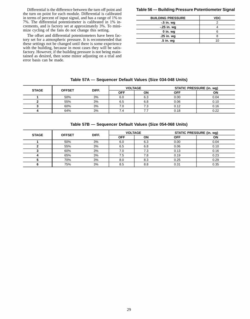
Differential is the difference between the turn off point andthe turn on point for each module. Differential is calibratedin terms of percent of input signal, and has a range of 1% to7%. The differential potentiometer is calibrated in 1% in-crements, and is factory set at approximately 3%. To mini-mize cycling of the fans do not change this setting.The offset and differential potentiometers have been fac-
tory set for a atmospheric pressure. It is recommended thatthese settings not be changed until there is some experiencewith the building, because in most cases they will be satis-factory. However, if the building pressure is not being main-tained as desired, then some minor adjusting on a trial anderror basis can be made.
Table 56— Building Pressure Potentiometer Signal
BUILDING PRESSURE VDC-.5 in. wg 2-.25 in. wg 40 in. wg 6
.25 in. wg 8.5 in. wg 10
Table 57A — Sequencer Default Values (Size 034-048 Units)
STAGE OFFSET DIFF.VOLTAGE STATIC PRESSURE (in. wg)
OFF ON OFF ON1 50% 3% 6.0 6.3 0.00 0.042 55% 3% 6.5 6.8 0.06 0.103 60% 3% 7.0 7.3 0.12 0.164 64% 3% 7.4 7.7 0.18 0.22
Table 57B — Sequencer Default Values (Size 054-068 Units)
STAGE OFFSET DIFF.VOLTAGE STATIC PRESSURE (in. wg)
OFF ON OFF ON1 50% 3% 6.0 6.3 0.00 0.042 55% 3% 6.5 6.8 0.06 0.103 60% 3% 7.0 7.3 0.13 0.164 65% 3% 7.5 7.8 0.19 0.235 70% 3% 8.0 8.3 0.25 0.296 75% 3% 8.5 8.8 0.31 0.35
29
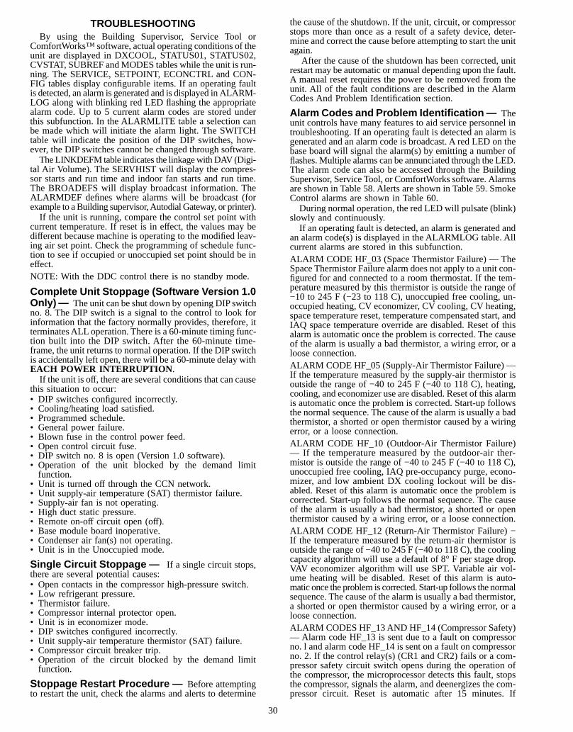
TROUBLESHOOTINGBy using the Building Supervisor, Service Tool or
ComfortWorks™ software, actual operating conditions of theunit are displayed in DXCOOL, STATUS01, STATUS02,CVSTAT, SUBREF andMODES tables while the unit is run-ning. The SERVICE, SETPOINT, ECONCTRL and CON-FIG tables display configurable items. If an operating faultis detected, an alarm is generated and is displayed in ALARM-LOG along with blinking red LED flashing the appropriatealarm code. Up to 5 current alarm codes are stored underthis subfunction. In the ALARMLITE table a selection canbe made which will initiate the alarm light. The SWITCHtable will indicate the position of the DIP switches, how-ever, the DIP switches cannot be changed through software.The LINKDEFM table indicates the linkagewithDAV (Digi-
tal Air Volume). The SERVHIST will display the compres-sor starts and run time and indoor fan starts and run time.The BROADEFS will display broadcast information. TheALARMDEF defines where alarms will be broadcast (forexample to aBuilding supervisor,Autodial Gateway, or printer).If the unit is running, compare the control set point with
current temperature. If reset is in effect, the values may bedifferent because machine is operating to the modified leav-ing air set point. Check the programming of schedule func-tion to see if occupied or unoccupied set point should be ineffect.NOTE: With the DDC control there is no standby mode.
Complete Unit Stoppage (Software Version 1.0Only)— The unit can be shut down by opening DIP switchno. 8. The DIP switch is a signal to the control to look forinformation that the factory normally provides, therefore, itterminatesALL operation. There is a 60-minute timing func-tion built into the DIP switch. After the 60-minute time-frame, the unit returns to normal operation. If the DIP switchis accidentally left open, there will be a 60-minute delay withEACH POWER INTERRUPTION .If the unit is off, there are several conditions that can cause
this situation to occur:• DIP switches configured incorrectly.• Cooling/heating load satisfied.• Programmed schedule.• General power failure.• Blown fuse in the control power feed.• Open control circuit fuse.• DIP switch no. 8 is open (Version 1.0 software).• Operation of the unit blocked by the demand limitfunction.
• Unit is turned off through the CCN network.• Unit supply-air temperature (SAT) thermistor failure.• Supply-air fan is not operating.• High duct static pressure.• Remote on-off circuit open (off).• Base module board inoperative.• Condenser air fan(s) not operating.• Unit is in the Unoccupied mode.
Single Circuit Stoppage — If a single circuit stops,there are several potential causes:• Open contacts in the compressor high-pressure switch.• Low refrigerant pressure.• Thermistor failure.• Compressor internal protector open.• Unit is in economizer mode.• DIP switches configured incorrectly.• Unit supply-air temperature thermistor (SAT) failure.• Compressor circuit breaker trip.• Operation of the circuit blocked by the demand limitfunction.
Stoppage Restart Procedure — Before attemptingto restart the unit, check the alarms and alerts to determine
the cause of the shutdown. If the unit, circuit, or compressorstops more than once as a result of a safety device, deter-mine and correct the cause before attempting to start the unitagain.
After the cause of the shutdown has been corrected, unitrestart may be automatic or manual depending upon the fault.A manual reset requires the power to be removed from theunit. All of the fault conditions are described in the AlarmCodes And Problem Identification section.
Alarm Codes and Problem Identification— Theunit controls have many features to aid service personnel introubleshooting. If an operating fault is detected an alarm isgenerated and an alarm code is broadcast. A red LED on thebase board will signal the alarm(s) by emitting a number offlashes. Multiple alarms can be annunciated through the LED.The alarm code can also be accessed through the BuildingSupervisor, Service Tool, or ComfortWorks software. Alarmsare shown in Table 58. Alerts are shown in Table 59. SmokeControl alarms are shown in Table 60.During normal operation, the red LED will pulsate (blink)
slowly and continuously.If an operating fault is detected, an alarm is generated and
an alarm code(s) is displayed in the ALARMLOG table. Allcurrent alarms are stored in this subfunction.ALARM CODE HF_03 (Space Thermistor Failure) — TheSpace Thermistor Failure alarm does not apply to a unit con-figured for and connected to a room thermostat. If the tem-perature measured by this thermistor is outside the range of−10 to 245 F (−23 to 118 C), unoccupied free cooling, un-occupied heating, CV economizer, CV cooling, CV heating,space temperature reset, temperature compensated start, andIAQ space temperature override are disabled. Reset of thisalarm is automatic once the problem is corrected. The causeof the alarm is usually a bad thermistor, a wiring error, or aloose connection.ALARM CODE HF_05 (Supply-Air Thermistor Failure) —If the temperature measured by the supply-air thermistor isoutside the range of −40 to 245 F (−40 to 118 C), heating,cooling, and economizer use are disabled. Reset of this alarmis automatic once the problem is corrected. Start-up followsthe normal sequence. The cause of the alarm is usually a badthermistor, a shorted or open thermistor caused by a wiringerror, or a loose connection.ALARM CODE HF_10 (Outdoor-Air Thermistor Failure)— If the temperature measured by the outdoor-air ther-mistor is outside the range of −40 to 245 F (−40 to 118 C),unoccupied free cooling, IAQ pre-occupancy purge, econo-mizer, and low ambient DX cooling lockout will be dis-abled. Reset of this alarm is automatic once the problem iscorrected. Start-up follows the normal sequence. The causeof the alarm is usually a bad thermistor, a shorted or openthermistor caused by a wiring error, or a loose connection.ALARM CODE HF_12 (Return-Air Thermistor Failure) −If the temperature measured by the return-air thermistor isoutside the range of −40 to 245 F (−40 to 118 C), the coolingcapacity algorithm will use a default of 8° F per stage drop.VAV economizer algorithm will use SPT. Variable air vol-ume heating will be disabled. Reset of this alarm is auto-matic once the problem is corrected. Start-up follows the normalsequence. The cause of the alarm is usually a bad thermistor,a shorted or open thermistor caused by a wiring error, or aloose connection.ALARM CODES HF_13AND HF_14 (Compressor Safety)— Alarm code HF_13 is sent due to a fault on compressorno. l and alarm code HF_14 is sent on a fault on compressorno. 2. If the control relay(s) (CR1 and CR2) fails or a com-pressor safety circuit switch opens during the operation ofthe compressor, the microprocessor detects this fault, stopsthe compressor, signals the alarm, and deenergizes the com-pressor circuit. Reset is automatic after 15 minutes. If
30

this fault occurs 3 times within 90 minutes, the compressorwill be locked out and manual reset will be required. To re-set, interrupt power to the control board. The possible causesare:1. High-pressure switch open. The high pressure switch is
wired in series with the control relay that energizes thesafety circuit. If the high-pressure switch opens duringcompressor operation, the compressor stops, and the stopis detected by the control board. The high pressure switchwill not lock out during the first 5 minutes of operation.
2. Low-pressure switch open. The low pressure switch is wiredin series with the control relay that energizes the safetycircuit. If the low-pressure switch opens during compres-sor operation, the compressor stops, and the stop is de-tected by the control board. The board ignores the lowpressure switch during the first 5 minutes of operation toprevent nuisance stops if low ambient operation isrequired.
3. Internal compressor protector open. The internal com-pressor protector is used on 06D model compressor. Theinternal protector switch is wired in series with the con-trol relay that energizes the safety circuit. If the internalprotector switch opens during compressor operation, thecompressor stops, and the stop is detected by the controlboard.
4. Freeze protection thermostat open. The freeze protectionthermostat switch is wired in series with the control relaythat energizes the safety circuit. If the freeze protectionthermostat switch opens during compressor operation, thecompressor stops, and the stop is detected by the controlboard.
5. Wiring error. A wiring error in the control safety circuitwill cause the modules to malfunction, and an error willbe indicated.Start the compressor. If the compressor starts, verify that
all stages of condenser fans are operational. Observe com-pressor operation to verify that compressor is working andcondenser fans are energized after compressor starts.ALARM CODE HF_15 (Thermostat Failure) — This alarmdoes not apply to a unit configured for and connected to aspace thermistor. If the thermostat is calling for heating andcooling at the same time, the unit will operate on a ‘‘firstcome first served’’ basis and an alarm will be generated. Analarm will also generate if stage 2 heating or cooling is calledfor before stage 1. Reset of this alarm is automatic once theproblem is corrected. The cause of the alarm is usually a badthermostat, a wiring error, or a loose connection.ALARMCODEHF_16 (Control Board Failure)—This alarmis generated with a faulty module. All outputs are turned off.The module must be replaced.If the analog to digital converter fails, the control board
will appear to operate correctly, however all set points willrevert back to default values in the event of a power failure.The module must be replaced.ALARM CODE HF_17 (Expansion I/O Board Failure) —This alarm is generated with a faulty module. If this is aresult of an analog to digital conversion, all outputs are turnedoff and the unit shuts down. If this is a result of the non-volatile RAM unable to read the set points, it will appear tooperate normally, however, in the event of a power failure,the device will operate to the default values upon resump-tion of power. The module must be replaced.ALARM CODE HF_18 (Timeclock Failure) — This alarmis not used with CV units configured for and connected to athermostat. The alarm is generated when clock data is out ofrange, or if the time does not advance. All outputs are turnedoff. Reset is automatic.ALARM CODE SE_05 (Loss of Communications with Ex-pansion Board) — If communication is lost with the expan-sion board all algorithms involving the expansion board willbe bypassed, and an alarm will be generated. This alarm will
reset automatically when the communication is restored.The outputs will turn on normally after the alarm conditionhas been reset. The probable cause for this condition is afaulty or improperly connected plug, a wiring error, or a faultymodule.ALARM CODE SE_14 (Indoor-Air Quality Sensor Failure)—This alarm is valid only when the expansion board is used,the IAQ alarm option is enabled, and the unit is equippedwith field-supplied IAQ sensors. The alarm is generated whenthe IAQ sensor is reading less than one volt. The reset methodis automatic and the alarm is cleared when the sensor readsat least 1.5 volts.ALARM CODE SE_15 (Linkage Failure — DAV SystemOnly) —A linkage failure alarm is generated when the link-age has stopped updating the TSM linkage tables within thelast 5 minutes.NOTE: This alarm can only be generated after linkage hasupdated the table at least one time since initialization.The unit controls enter the linkage default mode if the link-
age is enabled, but the communications link has been lost.With the controls having reverted back to stand-alone op-eration, the existing sensors, previously overridden by link-age, will be used. This may be caused by a loose connectionor a broken wire. Reset of this alarm is automatic once theproblem is corrected.ALARM CODES SE_16 to SH_19 (Fire Shutdown, SmokePurge, Evacuation, Pressurization)—When the unit is equippedwith an optional smoke control and a fire system is installed,these 4 modes are provided to control smoke within areasserviced by the unit. The unit must be equippedwith an econo-mizer, power exhaust, and the expansion module to supportthese modes. The building fire alarm system closes field sup-plied, normally open, dry contacts connected to the expan-sion module to activate the alarms. Reset of this alarm isautomatic once the problem is corrected.ALARM CODE SE_20 (Outdoor-Air Quality Sensor Fail-ure) — This alarm is valid only when the expansion boardis used, the OAQ alarm option is enabled, and the unit isequipped with field-supplied OAQ sensors. The alarm is gen-erated when the OAQ sensor is reading less than one volt.The reset method is automatic and the alarm is cleared whenthe sensor reads at least 1.5 volts.
ALARM CODE SE_21 (Supply-Air Thermistor Reset Fail-ure) — This alarm is valid only when enabled. This alarm isgenerated when the supply-air temperature sensor is readingless than one volt. The reset method is automatic and thealarm is cleared when the sensor reads at least 1.0 volts. Thecause of the alarm is usually a bad thermistor, a wiring error,or a loose connection.
ALARM CODE SE_22 (STO Sensor Failure) — This alarmis valid only when enabled. This alarm is generated whenthe STO sensor is open or shorted for greater than 5 seconds.Reset of this alarm is automatic once the problem is cor-rected. The cause of the alarm is usually a bad thermistor, awiring error, or a loose connection.
DATA STORAGE ERRORS — The control will also detectdata storage failures in Non-Volatile RAM, and generate Stor-age Failure (SF) alarms as they occur. When storage failureoccurs, the following logic will take place. If ‘‘good’’ valueof the failed configuration/service parameter is available inRAM, it will be used until the next power-up, at which timethe parameter will be loaded with its default value. In caseof a Storage Failure occurring before RAM has been up-dated, the default value will be loaded immediately. The stor-age failure alarms will be enunciated on CCN only. The alarmlight or LED blinks are not used. Table 61 shows a completelist of storage failure codes.A controls troubleshooting table is provided for use in ser-
vicing the unit. See Table 62.
31
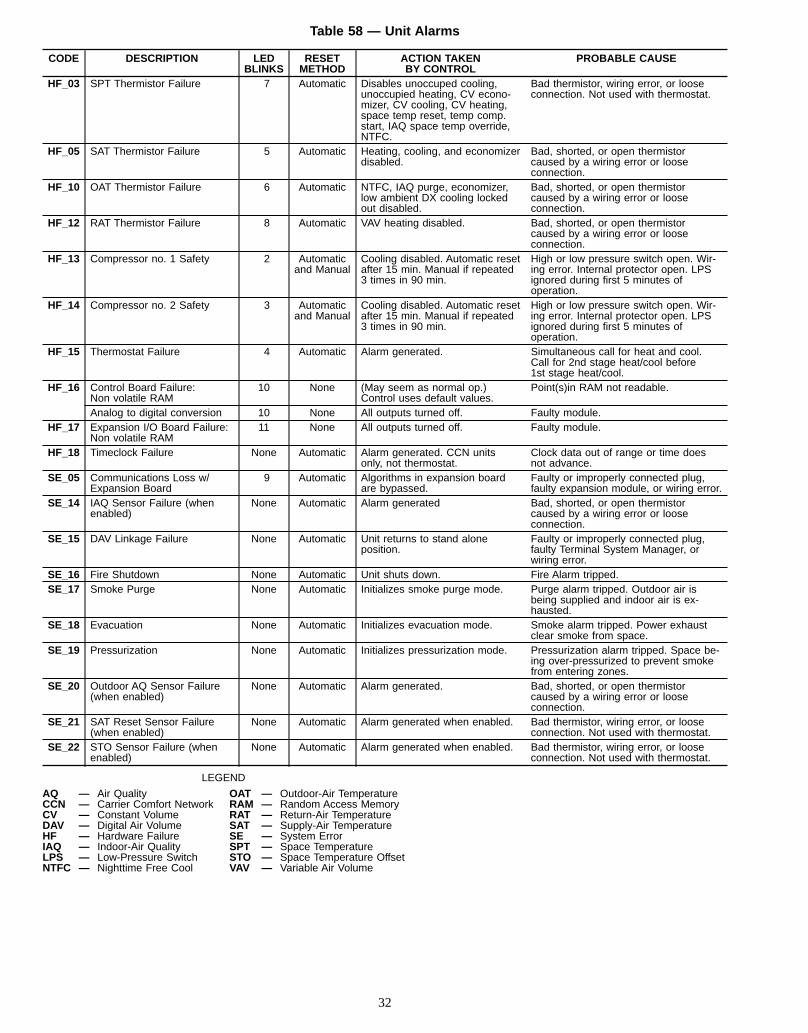
Table 58 — Unit Alarms
CODE DESCRIPTION LEDBLINKS
RESETMETHOD
ACTION TAKENBY CONTROL
PROBABLE CAUSE
HF_03 SPT Thermistor Failure 7 Automatic Disables unoccuped cooling,unoccupied heating, CV econo-mizer, CV cooling, CV heating,space temp reset, temp comp.start, IAQ space temp override,NTFC.
Bad thermistor, wiring error, or looseconnection. Not used with thermostat.
HF_05 SAT Thermistor Failure 5 Automatic Heating, cooling, and economizerdisabled.
Bad, shorted, or open thermistorcaused by a wiring error or looseconnection.
HF_10 OAT Thermistor Failure 6 Automatic NTFC, IAQ purge, economizer,low ambient DX cooling lockedout disabled.
Bad, shorted, or open thermistorcaused by a wiring error or looseconnection.
HF_12 RAT Thermistor Failure 8 Automatic VAV heating disabled. Bad, shorted, or open thermistorcaused by a wiring error or looseconnection.
HF_13 Compressor no. 1 Safety 2 Automaticand Manual
Cooling disabled. Automatic resetafter 15 min. Manual if repeated3 times in 90 min.
High or low pressure switch open. Wir-ing error. Internal protector open. LPSignored during first 5 minutes ofoperation.
HF_14 Compressor no. 2 Safety 3 Automaticand Manual
Cooling disabled. Automatic resetafter 15 min. Manual if repeated3 times in 90 min.
High or low pressure switch open. Wir-ing error. Internal protector open. LPSignored during first 5 minutes ofoperation.
HF_15 Thermostat Failure 4 Automatic Alarm generated. Simultaneous call for heat and cool.Call for 2nd stage heat/cool before1st stage heat/cool.
HF_16 Control Board Failure:Non volatile RAM
10 None (May seem as normal op.)Control uses default values.
Point(s)in RAM not readable.
Analog to digital conversion 10 None All outputs turned off. Faulty module.HF_17 Expansion I/O Board Failure:
Non volatile RAM11 None All outputs turned off. Faulty module.
HF_18 Timeclock Failure None Automatic Alarm generated. CCN unitsonly, not thermostat.
Clock data out of range or time doesnot advance.
SE_05 Communications Loss w/Expansion Board
9 Automatic Algorithms in expansion boardare bypassed.
Faulty or improperly connected plug,faulty expansion module, or wiring error.
SE_14 IAQ Sensor Failure (whenenabled)
None Automatic Alarm generated Bad, shorted, or open thermistorcaused by a wiring error or looseconnection.
SE_15 DAV Linkage Failure None Automatic Unit returns to stand aloneposition.
Faulty or improperly connected plug,faulty Terminal System Manager, orwiring error.
SE_16 Fire Shutdown None Automatic Unit shuts down. Fire Alarm tripped.SE_17 Smoke Purge None Automatic Initializes smoke purge mode. Purge alarm tripped. Outdoor air is
being supplied and indoor air is ex-hausted.
SE_18 Evacuation None Automatic Initializes evacuation mode. Smoke alarm tripped. Power exhaustclear smoke from space.
SE_19 Pressurization None Automatic Initializes pressurization mode. Pressurization alarm tripped. Space be-ing over-pressurized to prevent smokefrom entering zones.
SE_20 Outdoor AQ Sensor Failure(when enabled)
None Automatic Alarm generated. Bad, shorted, or open thermistorcaused by a wiring error or looseconnection.
SE_21 SAT Reset Sensor Failure(when enabled)
None Automatic Alarm generated when enabled. Bad thermistor, wiring error, or looseconnection. Not used with thermostat.
SE_22 STO Sensor Failure (whenenabled)
None Automatic Alarm generated when enabled. Bad thermistor, wiring error, or looseconnection. Not used with thermostat.
LEGEND
AQ — Air Quality OAT — Outdoor-Air TemperatureCCN — Carrier Comfort Network RAM — Random Access MemoryCV — Constant Volume RAT — Return-Air TemperatureDAV — Digital Air Volume SAT — Supply-Air TemperatureHF — Hardware Failure SE — System ErrorIAQ — Indoor-Air Quality SPT — Space TemperatureLPS — Low-Pressure Switch STO — Space Temperature OffsetNTFC — Nighttime Free Cool VAV — Variable Air Volume
32
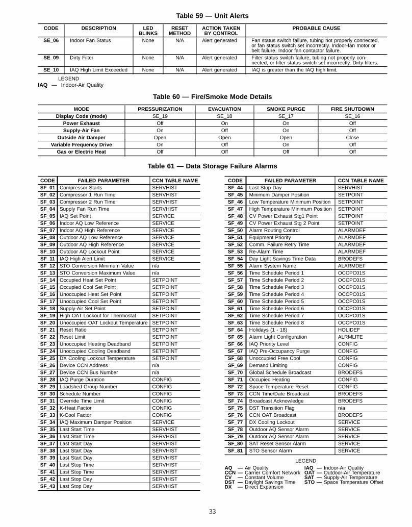
Table 59 — Unit Alerts
CODE DESCRIPTION LEDBLINKS
RESETMETHOD
ACTION TAKENBY CONTROL
PROBABLE CAUSE
SE_06 Indoor Fan Status None N/A Alert generated Fan status switch failure, tubing not properly connected,or fan status switch set incorrectly. Indoor-fan motor orbelt failure. Indoor fan contactor failure.
SE_09 Dirty Filter None N/A Alert generated Filter status switch failure, tubing not properly con-nected, or filter status switch set incorrectly. Dirty filters.
SE_10 IAQ High Limit Exceeded None N/A Alert generated IAQ is greater than the IAQ high limit.
LEGENDIAQ — Indoor-Air Quality
Table 60 — Fire/Smoke Mode Details
MODE PRESSURIZATION EVACUATION SMOKE PURGE FIRE SHUTDOWNDisplay Code (mode) SE_19 SE_18 SE_17 SE_16
Power Exhaust Off On On OffSupply-Air Fan On Off On Off
Outside Air Damper Open Open Open CloseVariable Frequency Drive On Off On Off
Gas or Electric Heat Off Off Off Off
Table 61 — Data Storage Failure Alarms
CODE FAILED PARAMETER CCN TABLE NAMESF_01 Compressor Starts SERVHISTSF_02 Compressor 1 Run Time SERVHISTSF_03 Compressor 2 Run Time SERVHISTSF_04 Supply Fan Run Time SERVHISTSF_05 IAQ Set Point SERVICESF_06 Indoor AQ Low Reference SERVICESF_07 Indoor AQ High Reference SERVICESF_08 Outdoor AQ Low Reference SERVICESF_09 Outdoor AQ High Reference SERVICESF_10 Outdoor AQ Lockout Point SERVICESF_11 IAQ High Alert Limit SERVICESF_12 STO Conversion Minimum Value n/aSF_13 STO Conversion Maximum Value n/aSF_14 Occupied Heat Set Point SETPOINTSF_15 Occupied Cool Set Point SETPOINTSF_16 Unoccupied Heat Set Point SETPOINTSF_17 Unoccupied Cool Set Point SETPOINTSF_18 Supply-Air Set Point SETPOINTSF_19 High OAT Lockout for Thermostat SETPOINTSF_20 Unoccupied OAT Lockout Temperature SETPOINTSF_21 Reset Ratio SETPOINTSF_22 Reset Limit SETPOINTSF_23 Unoccupied Heating Deadband SETPOINTSF_24 Unoccupied Cooling Deadband SETPOINTSF_25 DX Cooling Lockout Temperature SETPOINTSF_26 Device CCN Address n/aSF_27 Device CCN Bus Number n/aSF_28 IAQ Purge Duration CONFIGSF_29 Loadshed Group Number CONFIGSF_30 Schedule Number CONFIGSF_31 Override Time Limit CONFIGSF_32 K-Heat Factor CONFIGSF_33 K-Cool Factor CONFIGSF_34 IAQ Maximum Damper Position SERVICESF_35 Last Start Time SERVHISTSF_36 Last Start Time SERVHISTSF_37 Last Start Day SERVHISTSF_38 Last Start Day SERVHISTSF_39 Last Start Day SERVHISTSF_40 Last Stop Time SERVHISTSF_41 Last Stop Time SERVHISTSF_42 Last Stop Day SERVHISTSF_43 Last Stop Day SERVHIST
CODE FAILED PARAMETER CCN TABLE NAMESF_44 Last Stop Day SERVHISTSF_45 Minimum Damper Position SETPOINTSF_46 Low Temperature Minimum Position SETPOINTSF_47 High Temperature Minimum Position SETPOINTSF_48 CV Power Exhaust Stg1 Point SETPOINTSF_49 CV Power Exhaust Stg 2 Point SETPOINTSF_50 Alarm Routing Control ALARMDEFSF_51 Equipment Priority ALARMDEFSF_52 Comm. Failure Retry Time ALARMDEFSF_53 Re-Alarm Time ALARMDEFSF_54 Day Light Savings Time Data BRODEFSSF_55 Alarm System Name ALARMDEFSF_56 Time Schedule Period 1 OCCPC01SSF_57 Time Schedule Period 2 OCCPC01SSF_58 Time Schedule Period 3 OCCPC01SSF_59 Time Schedule Period 4 OCCPC01SSF_60 Time Schedule Period 5 OCCPC01SSF_61 Time Schedule Period 6 OCCPC01SSF_62 Time Schedule Period 7 OCCPC01SSF_63 Time Schedule Period 8 OCCPC01SSF_64 Holidays (1 - 18) HOLIDEFSF_65 Alarm Light Configuration ALRMLITESF_66 IAQ Priority Level CONFIGSF_67 IAQ Pre-Occupancy Purge CONFIGSF_68 Unoccupied Free Cool CONFIGSF_69 Demand Limiting CONFIGSF_70 Global Schedule Broadcast BRODEFSSF_71 Occupied Heating CONFIGSF_72 Space Temperature Reset CONFIGSF_73 CCN Time/Date Broadcast BRODEFSSF_74 Broadcast Acknowledge BRODEFSSF_75 DST Transition Flag n/aSF_76 CCN OAT Broadcast BRODEFSSF_77 DX Cooling Lockout SERVICESF_78 Outdoor AQ Sensor Alarm SERVICESF_79 Outdoor AQ Sensor Alarm SERVICESF_80 SAT Reset Sensor Alarm SERVICESF_81 STO Sensor Alarm SERVICE
LEGENDAQ — Air Quality IAQ — Indoor-Air QualityCCN — Carrier Comfort Network OAT — Outdoor-Air TemperatureCV — Constant Volume SAT — Supply-Air TemperatureDST — Daylight Savings Time STO — Space Temperature OffsetDX — Direct Expansion
33
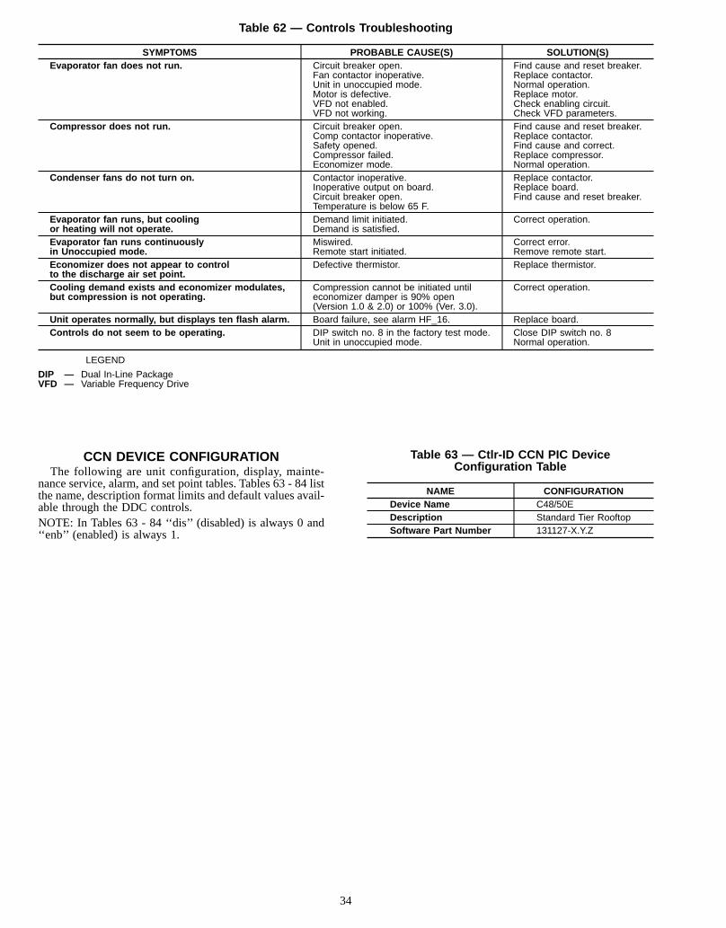
Table 62 — Controls Troubleshooting
SYMPTOMS PROBABLE CAUSE(S) SOLUTION(S)Evaporator fan does not run. Circuit breaker open.
Fan contactor inoperative.Unit in unoccupied mode.Motor is defective.VFD not enabled.VFD not working.
Find cause and reset breaker.Replace contactor.Normal operation.Replace motor.Check enabling circuit.Check VFD parameters.
Compressor does not run. Circuit breaker open.Comp contactor inoperative.Safety opened.Compressor failed.Economizer mode.
Find cause and reset breaker.Replace contactor.Find cause and correct.Replace compressor.Normal operation.
Condenser fans do not turn on. Contactor inoperative.Inoperative output on board.Circuit breaker open.Temperature is below 65 F.
Replace contactor.Replace board.Find cause and reset breaker.
Evaporator fan runs, but coolingor heating will not operate.
Demand limit initiated.Demand is satisfied.
Correct operation.
Evaporator fan runs continuouslyin Unoccupied mode.
Miswired.Remote start initiated.
Correct error.Remove remote start.
Economizer does not appear to controlto the discharge air set point.
Defective thermistor. Replace thermistor.
Cooling demand exists and economizer modulates,but compression is not operating.
Compression cannot be initiated untileconomizer damper is 90% open(Version 1.0 & 2.0) or 100% (Ver. 3.0).
Correct operation.
Unit operates normally, but displays ten flash alarm. Board failure, see alarm HF_16. Replace board.Controls do not seem to be operating. DIP switch no. 8 in the factory test mode.
Unit in unoccupied mode.Close DIP switch no. 8Normal operation.
LEGEND
DIP — Dual In-Line PackageVFD — Variable Frequency Drive
CCN DEVICE CONFIGURATIONThe following are unit configuration, display, mainte-
nance service, alarm, and set point tables. Tables 63 - 84 listthe name, description format limits and default values avail-able through the DDC controls.NOTE: In Tables 63 - 84 ‘‘dis’’ (disabled) is always 0 and‘‘enb’’ (enabled) is always 1.
Table 63 — Ctlr-ID CCN PIC DeviceConfiguration Table
NAME CONFIGURATIONDevice Name C48/50EDescription Standard Tier RooftopSoftware Part Number 131127-X.Y.Z
34
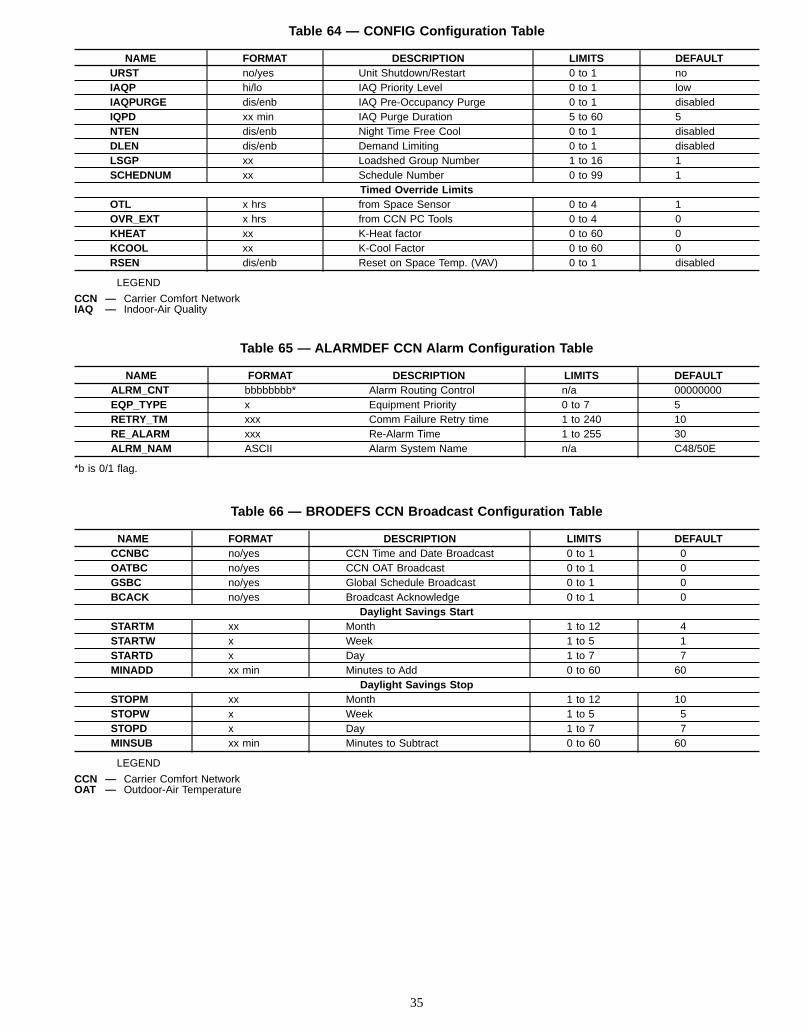
Table 64 — CONFIG Configuration Table
NAME FORMAT DESCRIPTION LIMITS DEFAULTURST no/yes Unit Shutdown/Restart 0 to 1 noIAQP hi/lo IAQ Priority Level 0 to 1 lowIAQPURGE dis/enb IAQ Pre-Occupancy Purge 0 to 1 disabledIQPD xx min IAQ Purge Duration 5 to 60 5NTEN dis/enb Night Time Free Cool 0 to 1 disabledDLEN dis/enb Demand Limiting 0 to 1 disabledLSGP xx Loadshed Group Number 1 to 16 1SCHEDNUM xx Schedule Number 0 to 99 1
Timed Override LimitsOTL x hrs from Space Sensor 0 to 4 1OVR_EXT x hrs from CCN PC Tools 0 to 4 0KHEAT xx K-Heat factor 0 to 60 0KCOOL xx K-Cool Factor 0 to 60 0RSEN dis/enb Reset on Space Temp. (VAV) 0 to 1 disabled
LEGEND
CCN — Carrier Comfort NetworkIAQ — Indoor-Air Quality
Table 65 — ALARMDEF CCN Alarm Configuration Table
NAME FORMAT DESCRIPTION LIMITS DEFAULTALRM_CNT bbbbbbbb* Alarm Routing Control n/a 00000000EQP_TYPE x Equipment Priority 0 to 7 5RETRY_TM xxx Comm Failure Retry time 1 to 240 10RE_ALARM xxx Re-Alarm Time 1 to 255 30ALRM_NAM ASCII Alarm System Name n/a C48/50E
*b is 0/1 flag.
Table 66 — BRODEFS CCN Broadcast Configuration Table
NAME FORMAT DESCRIPTION LIMITS DEFAULTCCNBC no/yes CCN Time and Date Broadcast 0 to 1 0OATBC no/yes CCN OAT Broadcast 0 to 1 0GSBC no/yes Global Schedule Broadcast 0 to 1 0BCACK no/yes Broadcast Acknowledge 0 to 1 0
Daylight Savings StartSTARTM xx Month 1 to 12 4STARTW x Week 1 to 5 1STARTD x Day 1 to 7 7MINADD xx min Minutes to Add 0 to 60 60
Daylight Savings StopSTOPM xx Month 1 to 12 10STOPW x Week 1 to 5 5STOPD x Day 1 to 7 7MINSUB xx min Minutes to Subtract 0 to 60 60
LEGEND
CCN — Carrier Comfort NetworkOAT — Outdoor-Air Temperature
35
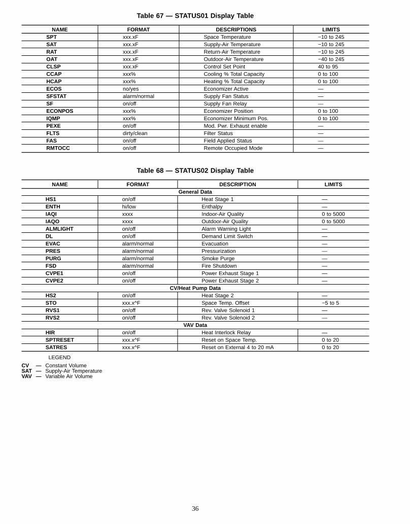
Table 67 — STATUS01 Display Table
NAME FORMAT DESCRIPTIONS LIMITSSPT xxx.xF Space Temperature −10 to 245SAT xxx.xF Supply-Air Temperature −10 to 245RAT xxx.xF Return-Air Temperature −10 to 245OAT xxx.xF Outdoor-Air Temperature −40 to 245CLSP xxx.xF Control Set Point 40 to 95CCAP xxx% Cooling % Total Capacity 0 to 100HCAP xxx% Heating % Total Capacity 0 to 100ECOS no/yes Economizer Active —SFSTAT alarm/normal Supply Fan Status —SF on/off Supply Fan Relay —ECONPOS xxx% Economizer Position 0 to 100IQMP xxx% Economizer Minimum Pos. 0 to 100PEXE on/off Mod. Pwr. Exhaust enable —FLTS dirty/clean Filter Status —FAS on/off Field Applied Status —RMTOCC on/off Remote Occupied Mode —
Table 68 — STATUS02 Display Table
NAME FORMAT DESCRIPTION LIMITSGeneral Data
HS1 on/off Heat Stage 1 —ENTH hi/low Enthalpy —IAQI xxxx Indoor-Air Quality 0 to 5000IAQO xxxx Outdoor-Air Quality 0 to 5000ALMLIGHT on/off Alarm Warning Light —DL on/off Demand Limit Switch —EVAC alarm/normal Evacuation —PRES alarm/normal Pressurization —PURG alarm/normal Smoke Purge —FSD alarm/normal Fire Shutdown —CVPE1 on/off Power Exhaust Stage 1 —CVPE2 on/off Power Exhaust Stage 2 —
CV/Heat Pump DataHS2 on/off Heat Stage 2 —STO xxx.x^F Space Temp. Offset −5 to 5RVS1 on/off Rev. Valve Solenoid 1 —RVS2 on/off Rev. Valve Solenoid 2 —
VAV DataHIR on/off Heat Interlock Relay —SPTRESET xxx.x^F Reset on Space Temp. 0 to 20SATRES xxx.x^F Reset on External 4 to 20 mA 0 to 20
LEGEND
CV — Constant VolumeSAT — Supply-Air TemperatureVAV — Variable Air Volume
36
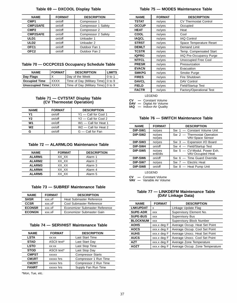
Table 69 — DXCOOL Display Table
NAME FORMAT DESCRIPTIONCMP1 on/off Compressor 1CMP1SAFE on/off Compressor 1 SafetyCMP2 on/off Compressor 2CMP2SAFE on/off Compressor 2 SafetyULD1 on/off Unloader 1ULD2 on/off Unloader 2OFC1 on/off Outdoor Fan 1OFC2 on/off Outdoor Fan 2
Table 70 — OCCPC01S Occupancy Schedule Table
NAME FORMAT DESCRIPTION LIMITSDay Flags X Day of the Week 0 to 1Occupied Time XXXX Time of Day (Military Time) 0 to 9Unoccupied Time XXXX Time of Day (Military Time) 0 to 9
Table 71 — CVTSTAT Display Table(CV Thermostat Operation)
NAME FORMAT DESCRIPTIONY1 on/off Y1 — Call for Cool 1Y2 on/off Y2 — Call for Cool 2W1 on/off W1 — Call for Heat 1W2 on/off W2 — Call for Heat 2G on/off G — Call for Fan
Table 72 — ALARMLOG Maintenance Table
NAME FORMAT DESCRIPTIONALARM1 XX_XX Alarm 1ALARM2 XX_XX Alarm 2ALARM3 XX_XX Alarm 3ALARM4 XX_XX Alarm 4ALARM5 XX_XX Alarm 5
Table 73 — SUBREF Maintenance Table
NAME FORMAT DESCRIPTIONSHSR xxx.xF Heat Submaster ReferenceCCSR xxx.xF Cool Submaster ReferenceECONSR xxx.xF Economizer Submaster ReferenceECONGN xxx.xF Economizer Submaster Gain
Table 74 — SERVHIST Maintenance Table
NAME FORMAT DESCRIPTIONLSTA xx:xx Last Start TimeSTAD ASCII text* Last Start DayLSTO xx:xx Last Stop TimeSTOD ASCII text* Last Stop DayCMPST xxxxx Compressor StartsCM1RT xxxxx hrs Compressor 1 Run TimeCM2RT xxxxx hrs Compressor 2 Run TimeFANRT xxxxx hrs Supply Fan Run Time
*Mon, Tue, etc.
Table 75 — MODES Maintenance Table
NAME FORMAT DESCRIPTIONTSTAT no/yes CV Thermostat ControlOCCUP no/yes OccupiedHEAT no/yes HeatCOOL no/yes CoolIAQCL no/yes IAQ ControlSTRST no/yes Space Temperature ResetDEMLT no/yes Demand LimitTCSTR no/yes Temp. Compensated StartIQPRG no/yes IAQ Pre-Occupancy PurgeNTFCL no/yes Unoccupied Free CoolPRESR no/yes PressurizationEVACN no/yes EvacuationSMKPG no/yes Smoke PurgeFIRES no/yes Fire ShutdownDAVCL no/yes DAV ControlFIELD no/yes Field/Startup TestFACTR no/yes Factory/Operational Test
LEGEND
CV — Constant VolumeDAV — Digital Air VolumeIAQ — Indoor-Air Quality
Table 76 — SWITCH Maintenance Table
NAME FORMAT DESCRIPTIONDIP-SW1 no/yes Sw 1 — Constant Volume UnitDIP-SW2 no/yes
no/yesSw 2 — Thermostat Operation
VAV-Space SensorDIP-SW3 no/yes Sw 3 — Expansion I/O BoardDIP-SW4 on/off Sw 4 — Field/Startup TestDIP-SW5 no/yes
enb/disSw 5 — CV-Modul. Power Exh.
VAV-Occupied HeatDIP-SW6 on/off Sw 6 — Time Guard OverrideDIP-SW7 no/yes Sw 7 — Electric HeatDIP-SW8 on/off Sw 8 — Heat Pump Unit
LEGEND
CV — Constant VolumeVAV — Variable Air Volume
Table 77 — LINKDEFM Maintenance Table(DAV Linkage Data)
NAME FORMAT DESCRIPTIONLNKUPDAT x Linkage Update FlagSUPE-ADR xxx Supervisory Element No.SUPE-BUS xxx Supervisory BusBLOCKNUM xxx Supervisory Block NumberAOHS xxx.x deg F Average Occup. Heat Set PointAOCS xxx.x deg F Average Occup. Cool Set PointAUHS xxx.x deg F Average Unocc. Heat Set PointAUCS xxx.x deg F Average Unocc. Cool Set PointAZT xxx.x deg F Average Zone TemperatureAOZT xxx.x deg F Average Occup. Zone Temperature
37
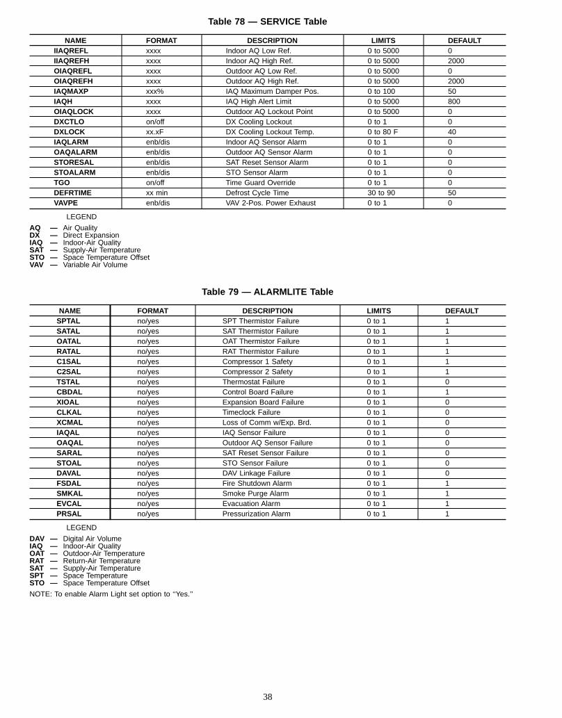
Table 78 — SERVICE Table
NAME FORMAT DESCRIPTION LIMITS DEFAULTIIAQREFL xxxx Indoor AQ Low Ref. 0 to 5000 0IIAQREFH xxxx Indoor AQ High Ref. 0 to 5000 2000OIAQREFL xxxx Outdoor AQ Low Ref. 0 to 5000 0OIAQREFH xxxx Outdoor AQ High Ref. 0 to 5000 2000IAQMAXP xxx% IAQ Maximum Damper Pos. 0 to 100 50IAQH xxxx IAQ High Alert Limit 0 to 5000 800OIAQLOCK xxxx Outdoor AQ Lockout Point 0 to 5000 0DXCTLO on/off DX Cooling Lockout 0 to 1 0DXLOCK xx.xF DX Cooling Lockout Temp. 0 to 80 F 40IAQLARM enb/dis Indoor AQ Sensor Alarm 0 to 1 0OAQALARM enb/dis Outdoor AQ Sensor Alarm 0 to 1 0STORESAL enb/dis SAT Reset Sensor Alarm 0 to 1 0STOALARM enb/dis STO Sensor Alarm 0 to 1 0TGO on/off Time Guard Override 0 to 1 0DEFRTIME xx min Defrost Cycle Time 30 to 90 50VAVPE enb/dis VAV 2-Pos. Power Exhaust 0 to 1 0
LEGEND
AQ — Air QualityDX — Direct ExpansionIAQ — Indoor-Air QualitySAT — Supply-Air TemperatureSTO — Space Temperature OffsetVAV — Variable Air Volume
Table 79 — ALARMLITE Table
NAME FORMAT DESCRIPTION LIMITS DEFAULTSPTAL no/yes SPT Thermistor Failure 0 to 1 1SATAL no/yes SAT Thermistor Failure 0 to 1 1OATAL no/yes OAT Thermistor Failure 0 to 1 1RATAL no/yes RAT Thermistor Failure 0 to 1 1C1SAL no/yes Compressor 1 Safety 0 to 1 1C2SAL no/yes Compressor 2 Safety 0 to 1 1TSTAL no/yes Thermostat Failure 0 to 1 0CBDAL no/yes Control Board Failure 0 to 1 1XIOAL no/yes Expansion Board Failure 0 to 1 0CLKAL no/yes Timeclock Failure 0 to 1 0XCMAL no/yes Loss of Comm w/Exp. Brd. 0 to 1 0IAQAL no/yes IAQ Sensor Failure 0 to 1 0OAQAL no/yes Outdoor AQ Sensor Failure 0 to 1 0SARAL no/yes SAT Reset Sensor Failure 0 to 1 0STOAL no/yes STO Sensor Failure 0 to 1 0DAVAL no/yes DAV Linkage Failure 0 to 1 0FSDAL no/yes Fire Shutdown Alarm 0 to 1 1SMKAL no/yes Smoke Purge Alarm 0 to 1 1EVCAL no/yes Evacuation Alarm 0 to 1 1PRSAL no/yes Pressurization Alarm 0 to 1 1
LEGEND
DAV — Digital Air VolumeIAQ — Indoor-Air QualityOAT — Outdoor-Air TemperatureRAT — Return-Air TemperatureSAT — Supply-Air TemperatureSPT — Space TemperatureSTO — Space Temperature Offset
NOTE: To enable Alarm Light set option to ‘‘Yes.’’
38
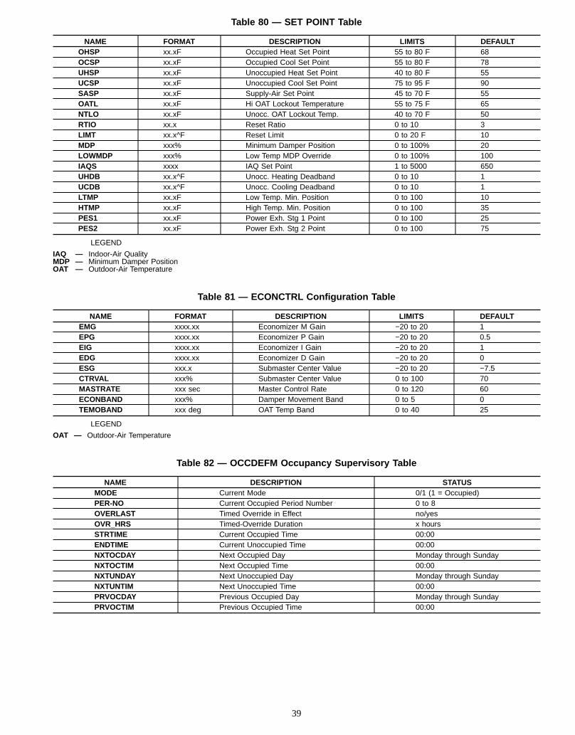
Table 80 — SET POINT Table
NAME FORMAT DESCRIPTION LIMITS DEFAULTOHSP xx.xF Occupied Heat Set Point 55 to 80 F 68OCSP xx.xF Occupied Cool Set Point 55 to 80 F 78UHSP xx.xF Unoccupied Heat Set Point 40 to 80 F 55UCSP xx.xF Unoccupied Cool Set Point 75 to 95 F 90SASP xx.xF Supply-Air Set Point 45 to 70 F 55OATL xx.xF Hi OAT Lockout Temperature 55 to 75 F 65NTLO xx.xF Unocc. OAT Lockout Temp. 40 to 70 F 50RTIO xx.x Reset Ratio 0 to 10 3LIMT xx.x^F Reset Limit 0 to 20 F 10MDP xxx% Minimum Damper Position 0 to 100% 20LOWMDP xxx% Low Temp MDP Override 0 to 100% 100IAQS xxxx IAQ Set Point 1 to 5000 650UHDB xx.x^F Unocc. Heating Deadband 0 to 10 1UCDB xx.x^F Unocc. Cooling Deadband 0 to 10 1LTMP xx.xF Low Temp. Min. Position 0 to 100 10HTMP xx.xF High Temp. Min. Position 0 to 100 35PES1 xx.xF Power Exh. Stg 1 Point 0 to 100 25PES2 xx.xF Power Exh. Stg 2 Point 0 to 100 75
LEGEND
IAQ — Indoor-Air QualityMDP — Minimum Damper PositionOAT — Outdoor-Air Temperature
Table 81 — ECONCTRL Configuration Table
NAME FORMAT DESCRIPTION LIMITS DEFAULTEMG xxxx.xx Economizer M Gain −20 to 20 1EPG xxxx.xx Economizer P Gain −20 to 20 0.5EIG xxxx.xx Economizer I Gain −20 to 20 1EDG xxxx.xx Economizer D Gain −20 to 20 0ESG xxx.x Submaster Center Value −20 to 20 −7.5CTRVAL xxx% Submaster Center Value 0 to 100 70MASTRATE xxx sec Master Control Rate 0 to 120 60ECONBAND xxx% Damper Movement Band 0 to 5 0TEMOBAND xxx deg OAT Temp Band 0 to 40 25
LEGEND
OAT — Outdoor-Air Temperature
Table 82 — OCCDEFM Occupancy Supervisory Table
NAME DESCRIPTION STATUSMODE Current Mode 0/1 (1 = Occupied)PER-NO Current Occupied Period Number 0 to 8OVERLAST Timed Override in Effect no/yesOVR_HRS Timed-Override Duration x hoursSTRTIME Current Occupied Time 00:00ENDTIME Current Unoccupied Time 00:00NXTOCDAY Next Occupied Day Monday through SundayNXTOCTIM Next Occupied Time 00:00NXTUNDAY Next Unoccupied Day Monday through SundayNXTUNTIM Next Unoccupied Time 00:00PRVOCDAY Previous Occupied Day Monday through SundayPRVOCTIM Previous Occupied Time 00:00
39
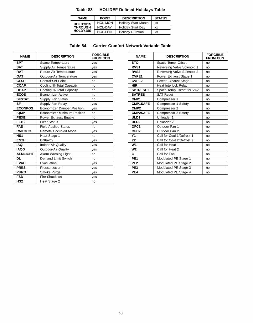
Table 83 — HOLIDEF Defined Holidays Table
NAME POINT DESCRIPTION STATUS
HOLDY01STHROUGHHOLDY18S
HOL-MON Holiday Start Month xxHOL-DAY Holiday Start Day xxHOL-LEN Holiday Duration xx
Table 84 — Carrier Comfort Network Variable Table
NAME DESCRIPTION FORCIBLEFROM CCN
SPT Space Temperature yesSAT Supply-Air Temperature yesRAT Return-Air Temperature yesOAT Outdoor-Air Temperature yesCLSP Control Set Point noCCAP Cooling % Total Capacity noHCAP Heating % Total Capacity noECOS Economizer Active noSFSTAT Supply Fan Status noSF Supply Fan Relay yesECONPOS Economizer Damper Position yesIQMP Economizer Minimum Position noPEXE Power Exhaust Enable noFLTS Filter Status yesFAS Field Applied Status noRMTOCC Remote Occupied Mode yesHS1 Heat Stage 1 noENTH Enthalpy yesIAQI Indoor-Air Quality yesIAQO Outdoor-Air Quality yesALMLIGHT Alarm Warning Light noDL Demand Limit Switch noEVAC Evacuation yesPRES Pressurization yesPURG Smoke Purge yesFSD Fire Shutdown yesHS2 Heat Stage 2 no
NAME DESCRIPTION FORCIBLEFROM CCN
STO Space Temp. Offset noRVS1 Reversing Valve Solenoid 1 noRVS2 Reversing Valve Solenoid 2 noCVPE1 Power Exhaust Stage 1 noCVPE2 Power Exhaust Stage 2 noHIR Heat Interlock Relay noSPTRESET Space Temp. Reset for VAV noSATRES SAT Reset noCMP1 Compressor 1 noCMP1SAFE Compressor 1 Safety noCMP2 Compressor 2 noCMP2SAFE Compressor 2 Safety noULD1 Unloader 1 noULD2 Unloader 2 noOFC1 Outdoor Fan 1 noOFC2 Outdoor Fan 2 noY1 Call for Cool 1/Defrost 1 noY2 Call for Cool 2/Defrost 2 noW1 Call for Heat 1 noW2 Call for Heat 2 noG Call for Fan noPE1 Modulated PE Stage 1 noPE2 Modulated PE Stage 2 noPE3 Modulated PE Stage 3 noPE4 Modulated PE Stage 4 no
40
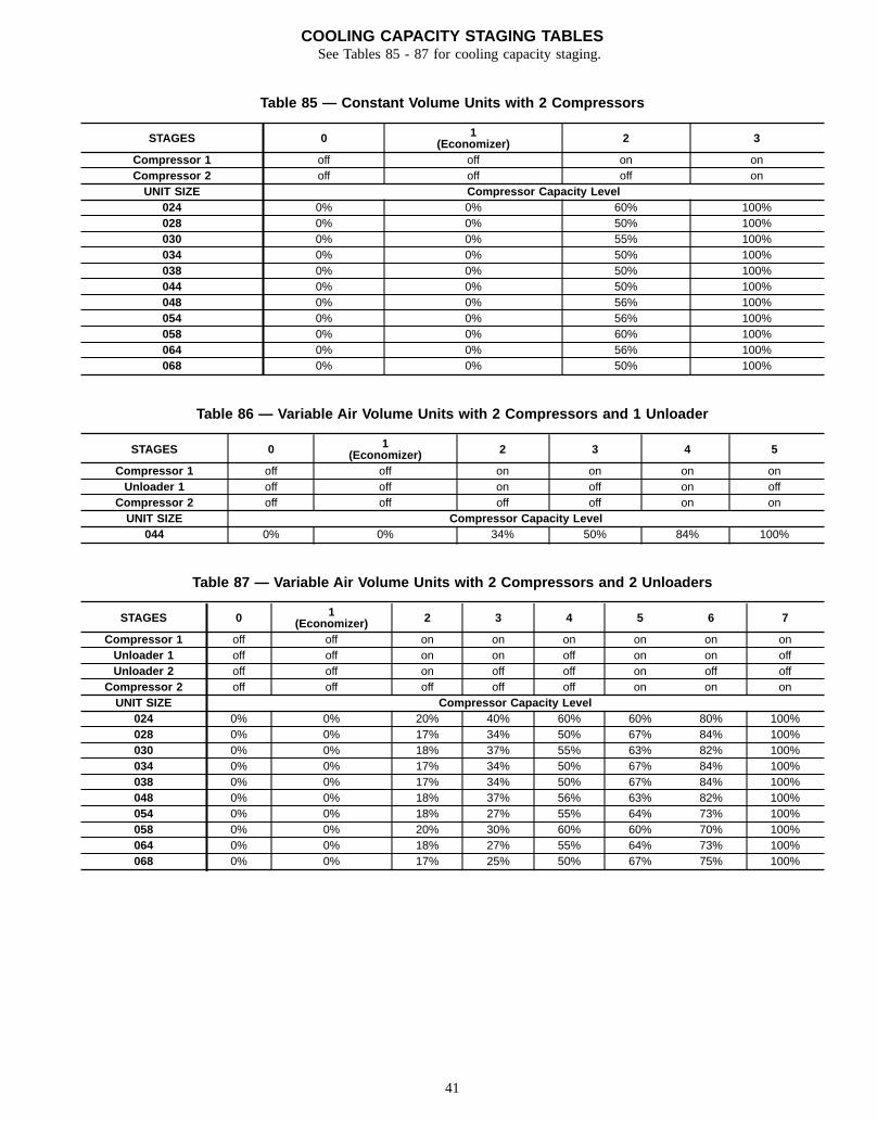
COOLING CAPACITY STAGING TABLESSee Tables 85 - 87 for cooling capacity staging.
Table 85 — Constant Volume Units with 2 Compressors
STAGES 0 1(Economizer) 2 3
Compressor 1 off off on onCompressor 2 off off off onUNIT SIZE Compressor Capacity Level
024 0% 0% 60% 100%028 0% 0% 50% 100%030 0% 0% 55% 100%034 0% 0% 50% 100%038 0% 0% 50% 100%044 0% 0% 50% 100%048 0% 0% 56% 100%054 0% 0% 56% 100%058 0% 0% 60% 100%064 0% 0% 56% 100%068 0% 0% 50% 100%
Table 86 — Variable Air Volume Units with 2 Compressors and 1 Unloader
STAGES 0 1(Economizer) 2 3 4 5
Compressor 1 off off on on on onUnloader 1 off off on off on off
Compressor 2 off off off off on onUNIT SIZE Compressor Capacity Level
044 0% 0% 34% 50% 84% 100%
Table 87 — Variable Air Volume Units with 2 Compressors and 2 Unloaders
STAGES 0 1(Economizer) 2 3 4 5 6 7
Compressor 1 off off on on on on on onUnloader 1 off off on on off on on offUnloader 2 off off on off off on off off
Compressor 2 off off off off off on on onUNIT SIZE Compressor Capacity Level
024 0% 0% 20% 40% 60% 60% 80% 100%028 0% 0% 17% 34% 50% 67% 84% 100%030 0% 0% 18% 37% 55% 63% 82% 100%034 0% 0% 17% 34% 50% 67% 84% 100%038 0% 0% 17% 34% 50% 67% 84% 100%048 0% 0% 18% 37% 56% 63% 82% 100%054 0% 0% 18% 27% 55% 64% 73% 100%058 0% 0% 20% 30% 60% 60% 70% 100%064 0% 0% 18% 27% 55% 64% 73% 100%068 0% 0% 17% 25% 50% 67% 75% 100%
41
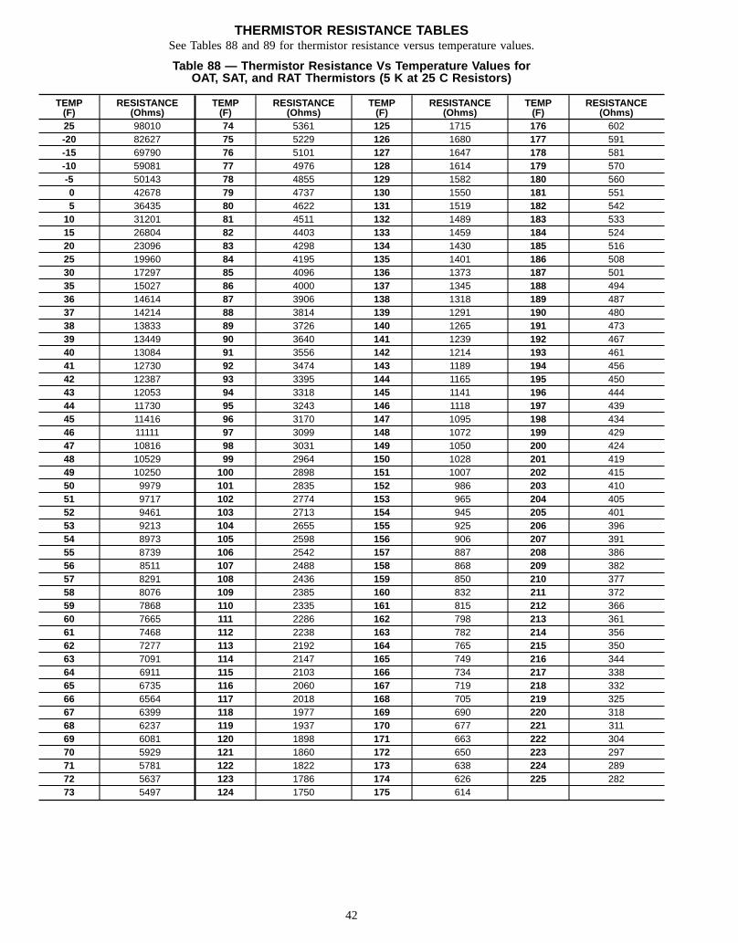
THERMISTOR RESISTANCE TABLESSee Tables 88 and 89 for thermistor resistance versus temperature values.
Table 88 — Thermistor Resistance Vs Temperature Values forOAT, SAT, and RAT Thermistors (5 K at 25 C Resistors)
TEMP(F)
RESISTANCE(Ohms)
TEMP(F)
RESISTANCE(Ohms)
TEMP(F)
RESISTANCE(Ohms)
TEMP(F)
RESISTANCE(Ohms)
25 98010 74 5361 125 1715 176 602-20 82627 75 5229 126 1680 177 591-15 69790 76 5101 127 1647 178 581-10 59081 77 4976 128 1614 179 570-5 50143 78 4855 129 1582 180 5600 42678 79 4737 130 1550 181 5515 36435 80 4622 131 1519 182 54210 31201 81 4511 132 1489 183 53315 26804 82 4403 133 1459 184 52420 23096 83 4298 134 1430 185 51625 19960 84 4195 135 1401 186 50830 17297 85 4096 136 1373 187 50135 15027 86 4000 137 1345 188 49436 14614 87 3906 138 1318 189 48737 14214 88 3814 139 1291 190 48038 13833 89 3726 140 1265 191 47339 13449 90 3640 141 1239 192 46740 13084 91 3556 142 1214 193 46141 12730 92 3474 143 1189 194 45642 12387 93 3395 144 1165 195 45043 12053 94 3318 145 1141 196 44444 11730 95 3243 146 1118 197 43945 11416 96 3170 147 1095 198 43446 11111 97 3099 148 1072 199 42947 10816 98 3031 149 1050 200 42448 10529 99 2964 150 1028 201 41949 10250 100 2898 151 1007 202 41550 9979 101 2835 152 986 203 41051 9717 102 2774 153 965 204 40552 9461 103 2713 154 945 205 40153 9213 104 2655 155 925 206 39654 8973 105 2598 156 906 207 39155 8739 106 2542 157 887 208 38656 8511 107 2488 158 868 209 38257 8291 108 2436 159 850 210 37758 8076 109 2385 160 832 211 37259 7868 110 2335 161 815 212 36660 7665 111 2286 162 798 213 36161 7468 112 2238 163 782 214 35662 7277 113 2192 164 765 215 35063 7091 114 2147 165 749 216 34464 6911 115 2103 166 734 217 33865 6735 116 2060 167 719 218 33266 6564 117 2018 168 705 219 32567 6399 118 1977 169 690 220 31868 6237 119 1937 170 677 221 31169 6081 120 1898 171 663 222 30470 5929 121 1860 172 650 223 29771 5781 122 1822 173 638 224 28972 5637 123 1786 174 626 225 28273 5497 124 1750 175 614
42
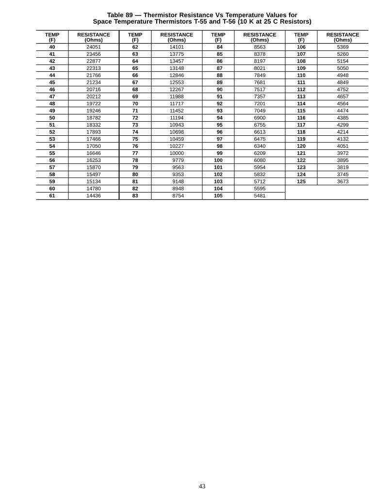
Table 89 — Thermistor Resistance Vs Temperature Values forSpace Temperature Thermistors T-55 and T-56 (10 K at 25 C Resistors)
TEMP(F)
RESISTANCE(Ohms)
TEMP(F)
RESISTANCE(Ohms)
TEMP(F)
RESISTANCE(Ohms)
TEMP(F)
RESISTANCE(Ohms)
40 24051 62 14101 84 8563 106 536941 23456 63 13775 85 8378 107 526042 22877 64 13457 86 8197 108 515443 22313 65 13148 87 8021 109 505044 21766 66 12846 88 7849 110 494845 21234 67 12553 89 7681 111 484946 20716 68 12267 90 7517 112 475247 20212 69 11988 91 7357 113 465748 19722 70 11717 92 7201 114 456449 19246 71 11452 93 7049 115 447450 18782 72 11194 94 6900 116 438551 18332 73 10943 95 6755 117 429952 17893 74 10698 96 6613 118 421453 17466 75 10459 97 6475 119 413254 17050 76 10227 98 6340 120 405155 16646 77 10000 99 6209 121 397256 16253 78 9779 100 6080 122 389557 15870 79 9563 101 5954 123 381958 15497 80 9353 102 5832 124 374559 15134 81 9148 103 5712 125 367360 14780 82 8948 104 559561 14436 83 8754 105 5481
43

Copyright 1998 Carrier Corporation
Manufacturer reserves the right to discontinue, or change at any time, specifications or designs without notice and without incurring obligations.Book 1 1 1Tab 1a 1b 5a
PC 111 Catalog No. 534-890 Printed in U.S.A. Form 48/50E-1T Pg 44 3-98 Replaces: New