instalación impulsor
TRANSCRIPT

8/8/2019 instalación impulsor
http://slidepdf.com/reader/full/instalacion-impulsor 1/20
ENERGIZER
INSTALLATION
AND
USER MANUAL
ELECTRIC FENCE PRODUCTS
Français au verso

8/8/2019 instalación impulsor
http://slidepdf.com/reader/full/instalacion-impulsor 2/20

8/8/2019 instalación impulsor
http://slidepdf.com/reader/full/instalacion-impulsor 3/20
TabLE OF CONTENTS PagE
IntroductIon 1
How ElEctrIc FEncIng works 1-2
InstallIng tHE ElEctrIc FEncE systEmI) InstallatIon tIps 2-3
II) typIcal FEncE sEt ups 3-4III) InstallIng tHE EnErgIzEr 5-8Iv) parmak® solar modEls dF-sp-lI & mag12-sp 8-9
troublEsHootIng guIdE 9-10
ElEctrIc FEncE maIntEnancE 10
typIcal layout For rotatIonal grazIng 10
parmak® EnErgIzEr product lIst 11-13
rEcommEndEd ground rods 13-15
Important saFEty tIps 15-16
warranty InFormatIon 16-17
(i)
8/8/2019 instalación impulsor
http://slidepdf.com/reader/full/instalacion-impulsor 4/20
parmak ® ElEctrIc FEncE products
PaRMaK ® ENERgIZERS – USER/INSTaLLaTION MaNUaL
CONgRaTULaTIONS!
y he he e he e eeie i he . sei eie ei eee e--he- e e e i hi eeie ieeeee ee eiii.
we ee e ei. o eieei ee i ieiei e e e ii e . y i i e ie hi eeh eee , ei i heeie h e ee hi ee.
thi i ih hh eh e ei i-
i ei. REaD THIS MaNUaL COMPLETELY bEFORE YOU STaRT TOINSTaLL YOUR ELECTRIC FENCE SYSTEM. thi e ii parmakeei ee he ii ee e. F he ii, ee ee eihe ee hee he hi ie e eieee pe mc m. c., 2000 Fe ae, k ci, mo 64108 ii eie ...
tHE warranty on parmak ElEctrIc FEncE EnErgIzErs Is sEt FortH onpagE 16 & 17.
How Electric Fencin Works:
the e eei ei i ee ie iie hei i e ii he eei h he he he he ee ie. pe ie eeei ee i eeie, ei ee ie. WaRNINg: Eei eei hi ie, hi ie. I’ eeiee ee e eei. ue ei ie ie ee he ee e. d e e eei ee he e eei ie e h e i heee ee. Fee i i eei i ee e ie ei e. sei ei i ee he ie he ee i e e , i , ie, , e., iei ee he ee e, hih e i heee ee.
ci e, e ee i eee hee i, e-e hi ie ee h e e i hee i.
The ence energizer must provide a high guard voltage on the charged wires to orce the shock current to jump rom the wire to the animal’s skin.the , hi, he i iehe ie he i’ i. a e 5000 v i hh 1/8 ih(3) hi. dei e e e ih e xie2000 v (he i e e ih ih e e).
The shock current travels through the body o the animal and into the earth ground hee
he e i. the ee he h he i ee he he, he i he h, he eih he i.
The shock current travels through the moist earth back to the ground rod and through the grounding wire back to the energizer to complete the circuit.the h e iiie he eie hi eei ii ii: he he ie, he i-’ , he eee he i eh , he eh , he eee eh he , he ie he eeie.
read all instructionswarning
1

8/8/2019 instalación impulsor
http://slidepdf.com/reader/full/instalacion-impulsor 5/20
whe ee h he he ie, e i ee he eh.the eeie i ie hi ee e hh he ee ie ii eeie e he he ie. whe hi ee e i-ee e he i he eeie, he e eee he ieh e i e ee.
the e he i, he e h e i eie i ee i eei. He e e e exie h e e ei ie ee eei ee. sie i e e eiie, i i e e e eeeie h i e iii ee e he ee.
wiie ee eie ei iei ee ei eeie ee-i. wi i h he ee hie i ie ei i. wi i ee ee ehi e e e e e. the eeei h eie he i i hh he ee eee he ie. yee he e e 5000v hh he i hi he e ih he ee. I i ee ee ee he ee iee he iiii he ee iiie he ee e.
TRaIN STOCK TO RESPECT NEW FENCE INSTaLLaTION
pe ii i i. reee, i i he ie h h he, heie he h he eeie eh ie he h he ie. tii i e i.
si iee ie, i, e ei -hi heih i. pe e ei ee ie ie ie. a hie e h ie he he i. the he he ee ih ee ie he i h ee i. ae e e eh ee, i e-ie i i i ie, he e e e e i e. te eie i ie eh ee ii ei. a h eh eei eeie he i e he hi ie ee hi ee.
INSTaLLINg THE ELECTRIC FENCE SYSTEM:a eei ee e ie he eeie, ee ie, i, , he e. the ee eeie e ee he e e (110-120 vac, 6 v e, 12 v e, s e) e e. the e ee ihe ihe he ee i e h e hih e. I i i hi he ie he he ihe , the shock current will ow rom the energizer,through the ence wire, through the animal to the earth ground, back through the moist earth to the ground rod, and back through the ground wire to the energizer to complete the circuit.
The earth grounding system is the most important variable in your electric ence
system. the eie he eee he i he eh, he e-ie he eh ie, he ei-e eee he eh he he i e.
FENCE ENERGIZER
CHARGED WIRE+
+
+
+-
GROUND
WIRE
MOIST SOIL
10’ 10’
10”
10”
20”
GROUND RODS
10’ 10’
6’Min.
2
I e e eei ei, hi e e ihi ee ei. I
eeiee i eee e ii eeii. d e e eei ei e i ei. I e e ei ih ee ei, i eeih he i ei i i ee.

8/8/2019 instalación impulsor
http://slidepdf.com/reader/full/instalacion-impulsor 6/20
INSTaLLaTION TIPS:the ee ei ei e ie eei ei. Fee i e ee e ie i he ee e. the ee ie heh he, e , ee, he eh. a eiee ee he ie ee hi ie. the ie e he ehe he ee ee e he he ee e.
the heih he ie h e xie 2/3 he heih he i. I hee e
iee ie i ihi he e, hee e he ie 2/3 he heih eh ie i. pe ee ie e e he i e .I e e e, he i i e e ee he ie hi i he ee .
TYPICaL FENCE SET-UPS
Sinle Wire Portle Fencea ie ie e ee e e e ee. the ie ie e xie he e heih he i. a ie ie ee i ei i
hee e iee ie i i he e. d e ie ie ee ee.
Multi Wire Psture Mnement FenceF e ih iee ie i, i-ie ee i eie ih he ie he e heih eh ie i. ce ii he ie ehe ee 1/4ie (400 ) ee he e ie ie.
Horse FenceHe e eie ee hei ii , he eeee e (eei he ihee). I i hee he ee -i i heee ee (ie. , i , ie, e), ee ee e e. I ii he ee ee, e b 1Z\x”Eei Ei-te (ie #894) iee iiii he he ee i ee.NOTE: whe ei he e ee i ee . mii ee he he ee e.
3
Ground Rod
Charged Wire
GroundBlack Output
Red
PaRMaK ® ENERgIZER
Charged Wire
Ground Rod
Charged Wire
GroundBlack Output
Red
PaRMaK ® ENERgIZER

8/8/2019 instalación impulsor
http://slidepdf.com/reader/full/instalacion-impulsor 7/20
wihi he ee ee, ee i eie ib e eei ee ie, e, 1/4” eei e ei, ei, e ee, e. d e e eei ee ee.
ground Return FenceI e ii e he eh e he h ehh he eh he . a i-ie ee ih ee ie he e i i hee ii. the i h h e he
ie e h. I he i e ie eh e he ie, i e e he he ie. ue ex ee he e ie ee1/4 ie (400 ). the i i he e 1/8 ie (200 ) e i i e hee he e he ee.
4
d ie ee ee ieei ee ie. di i e e
i i e ei i eh ie i ee ee. d e e ie eie ih eei ee.
FENCE ENERGIZER
CHARGED WIRE+
+
+
+
+
+-
GROUND WIRE
MOIST SOIL
10’ 10’
6’
Min.
10”
10”
10”
10”
12”
10’ 10’
GROUND RODS
Charged Wire
Charged Wire
Grounded Wire
Ground RodGround Rod
GroundBlack Output
Red
PaRMaK ® ENERgIZER

8/8/2019 instalación impulsor
http://slidepdf.com/reader/full/instalacion-impulsor 8/20
Woven Wire FenceI e ie i i he , he e he e ie he he ie e he e ie / he iie he ee i i. d he ie he e ie ee.
INSTaLLINg THE ENERgIZER110-120 V aC ENERgIZERS:a 110-120 v ac ee eeie e e i. the eeie e -ee i, , hih hii, ei. Eeie e ie i e, i. the eeie h e e he ee i.
IMPORTaNT INFORMaTION abOUT YOUR FENCE CHaRgERYour new aC powered fence chrer is equipped with diitl volte meter. theii ee e e he ee i i (exe: ei 3.5 = 3,500, 8.9 = 8,900 , 14.7 = 14,700 ).
the ei e i ee ii he (i.e. ee ).• A guard voltage of 2.0 or higher indicates a good fence for most shorthaired
i.• A guard voltage of 4.0 or higher indicates a good fence for most longhaired
i e.
o e e, e-e ee h eh, i i ee e ei i he i ee. a ii he ie i e he ee, i i - he iie e e iee ee .
I he e ei e 2.0 he ee h e hee h e , ee, ee i, e., i ee, e i i h ee
, , e. oe he e he ee h ee eiie he -e h e ee.
5
Ground Rod
Charged Wire
SIDE
VIEW
Insulated
Spacer
Grounded Wire
Ground
BlackOutputRed
PaRMaK ® ENERgIZER
che e e ei he e eei ee. se i eie he eei
ee e ieie ih “Eei Fee wi si”. ue p/bi i ie #2160.
110-120 a.c. e e For Indoor usEonly. not dEsIgnEd For outdoor usE.
sHock Hazard may EXIst IF usEd outdoors.
8/8/2019 instalación impulsor
http://slidepdf.com/reader/full/instalacion-impulsor 9/20
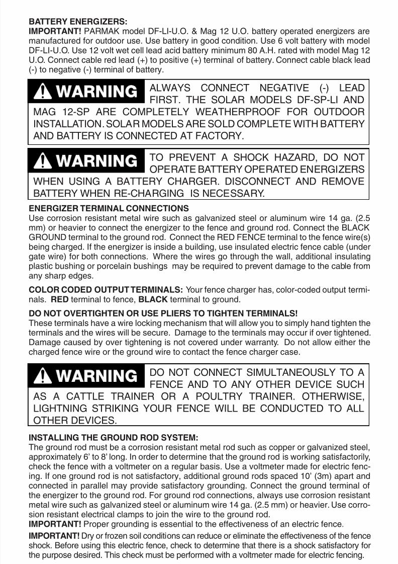
baTTERY ENERgIZERS:IMPORTaNT! parmak e dF-lI-u.o. & m 12 u.o. e ee eeie ee e. ue e i ii. ue 6 e ih edF-lI-u.o. ue 12 e e e i e ii 80 a.H. e ih e m 12u.o. ce e e e (+) iie (+) ei e. ce e e(-) eie (-) ei e.
ENERgIZER TERMINaL CONNECTIONSue i ei e ie h ie ee i ie 14 . (2.5) heie e he eeie he ee . ce he blackground ei he . ce he rEd FEncE ei he ee ie()ei he. I he eeie i iie ii, e ie eei ee e (ee ie) h ei. whee he ie hh he , ii iii hi ei hi e eie ee e he e h ee.
COLOR CODED OUTPUT TERMINaLS: y ee he h, -e ei-. RED ei ee, bLaCK ei .
DO NOT OVERTIgHTEN OR USE PLIERS TO TIgHTEN TERMINaLS!thee ei he ie i ehi h i i h ihe heei he ie i e ee. de he ei i e ihee.de e e ihei i ee e . d eihe hehe ee ie he ie he ee he e.
INSTaLLINg THE gROUND ROD SYSTEM:the e i ei e h e ie ee,xie 6’ 8’ . I e eeie h he i i ii,he he ee ih ee e i. ue ee e eei e-i. I e i i, ii e 10’ (3) ee i e ie i i. ce he ei
he eeie he . F ei, e i eie ie h ie ee i ie 14 . (2.5 ) heie. ue -i ei eei i he ie he .IMPORTaNT! pe i i eei he eeiee eei ee.
IMPORTaNT! d e i ii ee eiie he eeiee he eeh. bee i hi eei ee, he eeie h hee i h i he e eie. thi he e ee ih ee e eei ei.
6
always connEct nEgatIvE (-) lEad
FIrst. tHE solar modEls dF-sp-lI andmag 12-sp arE complEtEly wEatHErprooF For outdoorInstallatIon. solar modEls arE sold complEtE wItH battEryand battEry Is connEctEd at Factory.
to prEvEnt a sHock Hazard, do notopEratE battEry opEratEd EnErgIzErs
wHEn usIng a battEry cHargEr. dIsconnEct and rEmovE
battEry wHEn rE-cHargIng Is nEcEssary.
do not connEct sImultanEously to aFEncE and to any otHEr dEvIcE sucH
as a cattlE traInEr or a poultry traInEr. otHErwIsE,lIgHtnIng strIkIng your FEncE wIll bE conductEd to allotHEr dEvIcEs.

8/8/2019 instalación impulsor
http://slidepdf.com/reader/full/instalacion-impulsor 10/20
gROUNDINg INSTRUCTIONS FOR aC POWERED ENERgIZERS
thi eeie e e. I he eeie h i e , iee he i eei h ii h eie he eei e.
se eeie e eie ih hi eie i 3 e i he . ohe e eie ih ie 2 e (e e ie h he he e). bh e e 120 v ii.
3 blde groundin attchment Pluthe e iee i ie e h i e ie e
i e ih e ie.
I ei eee he i ee, e he i ie eihe f e ei. the ie ii hi e e h i ee ih ih e ie i he i ie.
thi e i e i 120 v ii h i h ie
he ie i eh a. a e e, hih ie he e iei ehe b c, e e e hi 2 e eee h ieh b i e e e i ie. the e e h ee i e e e (eh a) e ie ie eeii.the ee e ii e , he ie, exei he e e ee
ee h e e e x e. wheee he ei e, i e he i e e e.
2 blde Polrized Pluthe e iee i e h i e ie i e ih e ie. the i he e e . I i i , he
e. I i i e , he ie eeii i he e e.
gi hi i ie e ie eei e-e he ee e ei ( h i he ii ii,e 6). a ie ie e ee e e i i hih eei h e he eeie ee.
7
DANGERdo not usE a wEll, watEr pIpE, or yourpowEr systEm ground as a ground rod.
IF lIgHtnIng wErE to strIkE tHE FEncE, somE oF tHE lIgHtnIngcurrEnt wIll rEturn tHrougH tHE watEr or ElEctrIcalsystEm, crEatIng an EXtrEmEly Hazardous condItIon.
DANGER ImpropEr connEctIon oF tHE EquIpmEntgroundIng conductor or ImpropEr
usE oF tHE plug can rEsult In a dangErous ElEctrIc sHock.cHEck wItH a qualIFIEd ElEctrIcIan or sErvIcE pErsonnEl IFyou arE In doubt as to wHEtHEr tHE controllEr Is propErlygroundEd. do not modIFy tHE plug provIdEd wItH tHEcontrollEr. IF It wIll not FIt In tHE outlEt, HavE a propEroutlEt InstallEd by a qualIFIEd ElEctrIcIan.
(B) (C)
ADAPTER
METAL
SCREW
TAB FOR
GROUNDNG SCREW
GROUNDED
OUTLET BOX
GROUNDED
OUTLET
GROUNDING PIN (A)

8/8/2019 instalación impulsor
http://slidepdf.com/reader/full/instalacion-impulsor 11/20
I i i ee e exei , e ih e e h he he e eeie’ eie ; 2 e ie, 3 e ih e
. ree ei e .
aDDITIONaL INSTRUCTIONS FOR PaRMaK SOLaR MODELS DF-SP-LI & Mag12-SP
Solr Enerizer Instlltionche i h ie xi exe he hh he eie .pii he eeie ee ii h h he e. H he eeie he i e h i he i he he he i.
p ee he e hie he ih he e; h-ee, e he ie i e ei e, he e ee i-he. the ie he eeie i e e he e e e, e
he eeie i he 5 SUNNY ih he ih i he ii ehehe ie e he. CLOUDY DaYS DO NOT COUNT FOR THE NEEDED5 SUNNY DaYS.
the e e ehe ei e e e ehi iih 6 12 e he (ie #951 – 6 #952 – 12 ). the e he eie p ee. the e he i ehe he e ihi48 72 h.
Solr Enerizer Opertionthe parmak s eeie’ e e ih i eei e he
he ie e. the ee he he i iie he i ei e he ee. the eeie i ee i ih ii. Hee,h ih ii ei exee ei ie, hi e he eee exee . I hi he i i eee h he eeie e e he e ehe he e i ih 5 e e ee he eeie ehe i e he eihe ie #951 (6) ie #952 (12 ) eei hih e . wih e he, ehee ii 48 h.
INSTaLLaTION
Loction nd Mountin of Enerizera i e e ie i clEan, dry locatIon hee i - i eeie. mihe he ii e eee.m eeie ih eie i he eeie. do notplacE EnErgIzEr on Floor or sHElF. see ee eeie ee-ie hehe he i e.
the , e, ehe e e ie hee. m eeieee ee i 10” 2x4 . I eeie i ie e ie ee ie, he ie e ehe he e-eie ee hi eeie . d he ie heeie e.
Specil Note - Solr Modelsthe ee e e ie ee ii.Fe eeie e duE soutH i he nhe Heihee (u.s.a.) duEnortH i she Heihee. m eeie e. m hee -e i e i ie ih he eie . s e i e eeie ei e ie xi e ee ei eie. I e eei, e ih e ii xi ee ei. ue ii i,e. i ee e e.
8
DANGERdo not modIFy tHE plug provIdEd wItH tHEcontrollEr. IF It wIll not FIt tHE outlEt,
HavE a propEr outlEt InstallEd by a qualIFIEd ElEctrIcIan.

8/8/2019 instalación impulsor
http://slidepdf.com/reader/full/instalacion-impulsor 12/20
TROUbLESHOOTINg gUIDE
the e ie e eei ee e i he e e:
1) t e he eeie, ie i he ee ee eee he (+) posI-tIvE ground (-) ei ih eei ee e ee eie eeiei ( e ee i e ee i ee he ee e).the e h e 5000 v e e. I he ee-i ee e ee, e e e ee ee i h ie ihe e fh i he eeie i i e. I he ee ee, e e iee ie ie h he ei.y h e e 1/10 ih (2.5 ) i he h i heeeie i i e.
wih he eeie ee he ee, ee he e eee he ee ei he eeie. I he e i e h 2000 v, he he hei:
) thee e ie ei eee he e ie heee. me e h he ee ie e ie eh he h ii- he ie i-ie ee e ee ehe.
) thee e ie ei eee he ie eh . mee h ex ie he ee ie e ee he eie, he ie. me e h he he ie i hi e
e e ii he . me e h he ie e hh hee i e h.
) peh he ee he he ie i h he ie eeie e i. me e h he he ie e he ee i e eehi. y ee ee ee he ee ie / e hihe eeie. miiie he he eeie iei ei ee he eie ee e i.
2) I he eeie e ee he eeie ei i ee hee ee e i i ee he ee ee e i he -e ee ee he ee, he he he i:
) the e ee he eh he e e e. me he e hee he eh i i e. a e / e e ie i-ie ee. t ei i ee, e e e (e ) i he he ie 100 (30 ) he eeie ie he ee . ui eei eee ee, ee he e eee he ie e he ihe eh 6 (2 ) he . I he ee e i e h 500v, he ee he . a e h e ie ihe i eh e 10 (3 ) he e ee he .
ree he e ih he ee hi i ee. I hee i , he i he ie hi ee i-ie eih e ie i he e he ee.
) the he ie e ie hi ee, he ie e i e, he ie e i he ie h e e. I hee e,he e he ee ee e e he i he hii . ue i he i e ee .
) a he ie e i he i hh e. rei he ee
9
ree eonly withp pehe eheee i (ge ce) e eihe ie #901 (6 ) ie
#902 (12 ) eei hih e . ui he e i ee he ee ee ee.
note

8/8/2019 instalación impulsor
http://slidepdf.com/reader/full/instalacion-impulsor 13/20
e ihe ie ie h e hi e.
) che e ie i-ie ee e ie he eh-e. reee h i i he i h ee he eei ii. do not ehe e ie ehe he ee i e he!
e) thee e e e ie i he he ie() he ei he e e. ree e ie ei ie ee ee-i ei. diii e e. I ei iee ie e h
ii e eei ei ee ei, e b e e ie#676 ee .
) the eie he he ie e iii he e he ee. d e e eei ee ie e he eeie eeie ee ee.
) the eie e eei ee ie i hih ee ih eehi he ie. ree ih ee e ee ie.
TRaININg aNIMaLS TO RESPECT ELECTRIC FENCINg
ai h e ie ee he ee ii he i i e. I
e he i he ee ih ee. F exe, i i e ee i iie. reee, he he ie e he e heih eh iei ei ie.
ELECTRIC FENCE MaINTENaNCE
Eei ei i ei, eeie e ie ee, i eeie e ii eii. Exee hei eee ee i eee ee he e ee eeie. pe eei ee ie eee i eeie he ee e hi he he ie.
TYPICaL SERVICINg:
mii ee ee ei.1.ree eei eei ee ie.2.che eei ee e i ih ee e eei ei. ue3.p e ee ie #814 ie #815 eie e e eei ee.d e ee.che ee e e i ee h he e i e.4.
IMPORTaNT! se e eei ee ie e ie. d eeei ee ie e e e ih i e.
10
TYPICaL LaYOUTFOR ROTaTIONaL gRaZINg pee b Fee
parmak® pe Eei Fee

8/8/2019 instalación impulsor
http://slidepdf.com/reader/full/instalacion-impulsor 14/20
PaRMaK ENERgIZER PRODUCTS*
baTTERY ENERgIZERS
Model DF-SP-LI6 volt - Solr/bttery OpertedAmerica’s frst solar-powered electric encer
ne e e e•
Exie i-i ee ee•wi ee 21 i e•
wehe, e.•
see ehee 6 e•
che 25 ie ee•
100% American made • UL Listed•
Model DF-LI-UO6 volt - bttery Operted• Small to medium pastures.
• 100% solid-state with increased shock output
• Fully weatherproof, portable outdoor model• Build-in operational light.
• Use a Ray O Vac #641 or equivalent
• Charges up to 25 miles of fence • UL Listed
MODEL EM-20012 volt - bttery Operted• UL Listed
• Designed for small pastures. Not recommended for use with
ee.
• High efciency to provide up to 2 1/2 months of operation on
80 -h e e (e e e) ee ei ee e ehe.
• Low impedance
• Operational light ashes red each time the energizer pulses.
• Weatherproof, outdoor installation
Model Mag.12 U.O.12 volt - bttery Operted12 volt advanced solid state circuitry
• New compact design
• Performance meter that shows condition of fence
• Low impedance for maximum power, longer life• Ideal for livestock or predator control
• Medium to large pastures
• Weatherproof, portable - outdoor model
• Use with 12 volt storage battery, complete with battery clamps
• Charges up to 30 miles of fence • UL Listed
Model Mag.12-SP12 volt - Solr/bttery OpertedSolar powered, uses ree energy rom the sun • Low impedance for maximum power, longer life
• Performance meter that shows condition of fence• No operating costs
• America’s rst solid state solar powered electric fencer
• State-of-the-art solar panel for superior charging power
• Complete with sealed 12 volt rechargeable battery
• Weatherproof, portable outdoor model
• Charges up to 30 miles of fence
• UL Listed
11

8/8/2019 instalación impulsor
http://slidepdf.com/reader/full/instalacion-impulsor 15/20
110-120 VOLT aC ENERgIZERS
MODEL HS-100110-120 volt aC Operted• UL Listed
• Designed for small pastures. Not recommended for use with
ee.
• Low impedance
• Equipped with dual red/green ashing lights. The greenih iie h hee i e he ee. re
iie h he he i ei e he ee ie.
I ei, h ih i ee ee e.
• Install in clean, dry location protected from rain, snow,
hih hii, e.
Model S.E. 4110-120 volt - aC Opertion• Low Impedance designed specically for large pastures
• Single or multi-wire high tensile fences
• Advanced solid state circuitry• Parmak’s exclusive built-in digital performance meter.
• Ideal for controlled grazing of livestock
• For indoor installation
• Charges over 50 miles of fence
• UL Listed • US & Canada
Model Mrk 7110-120 volt - aC Opertion Low impedance or medium to large pastures
• Single or multi-wire high tensile fence.
• Advanced solid state circuitry• Parmak’s exclusive built-in digital performance meter.
• Ideal for livestock or predator control.
• For indoor installation.
• Charges up to 30 miles of fence
• UL Listed • US & Canada
• Low impedance
Model FM-2
110-120 volt - aC Opertion• Small to medium pastures
• Advanced solid state circuitry
• Shocks through wet weeds & brush
• Built-in operational light
• For indoor installation
• Charges up to 15 miles of fence
• UL Listed • US & Canada
Model RM-1110-120 volt - aC OpertionThe most technically advanced Parmak encer
• Digital meter shows voltage on fence-accurate within 100 volts• Ultra-high visible multi-color LED lights shows condition of fence
• Audible and visible “Shut Down Alarm” sounds
he ee i ii e.
• Low impedance - For control of livestock or predators.
• Advanced built-in computer controlled circuitry
• Rugged high impact ABS housing
• Color coded fence and ground terminals
• Charges over 100 miles of fence
12
US
US

8/8/2019 instalación impulsor
http://slidepdf.com/reader/full/instalacion-impulsor 16/20
Prmk Stndrd Fence Tester- Item #814• For use with fence energizers with peak voltage of
5000
Prmk Professionl Fence Tester- Item #815• Easy to read analog design
• Reads to 10,000 volts• Sold complete with storage pouch
• No batteries required
*SPECIFICaTIONS aRE SUbjECT TO CHaNgE WITHOUT NOTICE.
NOTE: the ee e e ee ih e ee eie eei ei. a e ee i e ee i ee ee e.a e ei e fh e ee ee e e e ee ie he
h ie ee. y i he e h ih he fh i he he ee ii e.
NOTE: the “ie ee” h e he eeie ee he e ie, he ee he he ie, he ee i, he e ee ie he i ii. Fee e eii eiee e ie he e ee e p eeie ihhe e eeie. gee, he e eie, he eeie h -ie he hihe e e i e he eeie.
SYMbOLS
SYMbOL MEaNINg
CaUTION: to rEducE tHE rIsk oF ElEctrIc sHock,do not rEmovE covEr (or back). rEFEr sErvIcIngto qualIFIEd pErsonnEl
WaRNINg: rIsk oF FIrE. rEplacE FusE as markEd.
RECOMMENDED gROUND RODS
3/8” 5/8”iee, 6 8 i ei e h ie ee.die ii 6 8 ee ee i ee i eh.
DO NOT e ie ee e hih h ie e ee ii i i eeii.
DO NOT e ii e ie ee.
DO NOT i ee ihi 50 ee ii e. thi e ii. y ee he must HavE i’ ee e.p e e i ee e i e ihi 50 ee ii .
DO i ihi 20 ee he.
DO e h ie .
a v
13
F E N C E
C L O T U R E
5 0 0 0 V
4 0 0 0 V
3 0 0 0 V
2 0 0 0 V
1 0 0 0 V G
R O U N D
0
1
2 3
4
5
6
7 8
91 0
K v
8 2 0 3 E
l e c t r i c
F e n c e V
o l t m e t e
r

8/8/2019 instalación impulsor
http://slidepdf.com/reader/full/instalacion-impulsor 17/20
DO replace ground rods every two years or so. The ground rods will rust under ground andover time will no longer be a good ground.
SANDY, ROCKY OR CLAY SOIL GROUNDS
In some areas you can not drive a ground rod 6 to 8 feet deep due to rocks, etc. In these ar-eas it is recommended that ground rods be driven at a 45° angle as deep as possible. Drive4 or 5 ground rods in a circle like the spokes of a wheel. Connect all ground rods together
with a ground wire and then back to the ground terminal of the fence charger.
UNDERGROUND WIRING
If you plan to run charged wire underground from your fence charger to the fence line youmust install it properly using the correct material or your fence will be “grounded out”.
DO NOT use standard household insulated wiring for underground wiring.
DO NOT use underground wiring by itself.
DO use insulated underground wire specifically designed for high voltage electric fence suchas Baygard item #693 insulated cable insulated for a minimum of 15,000 volts.
DO run underground wire through PVC (plastic) conduit. Bring both ends of conduit a minimumof 6” above ground level. Caulk both ends of conduit so that water cannot enter conduit.
INDOOR INSTALLATION OF FENCE CHARGE
All 110-120 Volt A.C. power line operated models MUST BE installed in a clean, dry locationprotected from the weather - rain, snow, etc. The charged wire going from the fence chargerto the fence line MUST BE insulated from the building wall, etc. and also insulated fromground wire going from fence charger to ground rods.
DO NOT allow charged wire to contact building wall or return ground wire.
DO use high voltage insulated wire, insulated for a minimum of 15,000 volts specificallydesigned for use with electric fence chargers. Baygard insulated electric fence cable item #693 is an excellent choice.
IMPORTANT INFORMATION
POOR GROUND WILL DAMAGE YOUR FENCER AND WILL DECREASE SHOCK ONFENCE LINE
Your low impedance fencer MUST BE properly grounded. Three (3) eight foot ground rods,ten feet apart, driven eight feet deep into permanently moist earth are recommended.
NOTE: sandy, rocky or clay soil conditions cause a poor ground. In these areas additional
ground rods may be needed to adequately ground the fence. (In some locations as manyas 5 or 6 grounds rods are needed). If you DO NOT properly ground your fence, your fencecharger will be damaged and you will have decreased or no shock at all on the fence line.
THE BIGGEST CAUSE FOR A FAILED ELECTRIC FENCE IS “HUMAN”The biggest cause for a failed electric fence is HUMAN!! Most people do not fully understandwhat it takes to correctly install and maintain an electric fence. They do not understand thatany electric fence requires routine maintenance to keep adequate power on the fence ormaybe they are just too busy to take the time to do the required maintenance.
14
DO NOT use standard household insulated wiring

8/8/2019 instalación impulsor
http://slidepdf.com/reader/full/instalacion-impulsor 18/20
the ie iee e e iee ( ), e-i, i ie ie, i eei ee he (e eeee), e. I e he “h ”:
POOR KNOWLEDgE - TOO COMPLICaTED - TOO bUSY TO DO ROUTINEMaINTENaNCE
I e eei ee, e he ie e h e i he ee ii
i. b he e eei ee he e e hh.
IMPORTaNT!Typicl minimum shock requirements:• Animals such as horses and pigs trained to electric fencing: 1000V• Animals such as cattle and short haired stock trained to electric fencing: 2000V• Predators (wild): 5000V• Above rating based on well insulated single wire fence
thi ie h eiee ie ii ee . me e he he
ih e ee ie ii he h ie i i hee eie.
IMPORTaNT SaFETY TIPSUSE COMMON SENSE WHEN USINg ELECTRIC FENCE CHaRgERSInstallatIon:I he ee he e ii ie ih eh he. the ee he i iie hehe i i e ie i . I e e ie i e, , i. the he eei ei eee ehe.
DO NOT eei ee ie ih he e.
DO NOT i e, hh e eei ee. whe i eei ee –e e ee he oFF.
DO NOT hie ih eei ee.
DO NOT eei e ie, i, eie.
DO NOT eei ee hih e i ee ei ee.
DO NOT i ee ie e eeh ehe e ie.
DO NOT use more than one fence charger on the same fence.
DO NOT e e ie ei e he he ee ie. I ii ,ee, e., eeh ee ie, e -ie ei ie ee ie.
DO NOT e ie fe ei i , ee, e. eeh ee ie.
WaRNINg SIgNS:whee i h e, i i eee (eie i e e) h he ee-i ee e ieie ii ElEctrIc FEncE warnIng sIgns. thee i eie e ee. ue p i i ie #2160. chee e ee i eei ee he.
SaFETY FIRST:do not e ei he e. a ei e ee ie h-ie eie ee .
15

8/8/2019 instalación impulsor
http://slidepdf.com/reader/full/instalacion-impulsor 19/20
sErvIcE oF doublE-InsulatEd applIancEs:I e-ie e, e ii e ie ie i.n eie i e i ie i he e-ie -e, h e eie i e e he e. seii e-ie e eie exee e ee he e, he e ie eie ee. reee e-ie -e e iei he he ee. a e-ie e i eih he “doublE InsulatIon” “doublE InsulatEd”. the e
ii (e ihi e).
I e h ie he ( i ). w e eeihie h he eei ee i i ei.nEvEr i e eei ee ie.
USE CaUTION WHEN OPENINg bOX aND WHILE HaNDLINg FENCER CHaRgER
the ee he i eie ih he e.
do not ee he ei x.
whe hi ee he, i h:do not h ei ee he.
SOLaR FENCE CHaRgER IS HEaVY.do not ee he hi e ee. di -e e e e e i i e eehe. d ee he i h ee ie e e ie h he , ee i ee he. do not h ei.
y ee ee i eie ih ei ehee ee e i -e. be e he ee i ee ee i ee e. tehe e, e ee e h i he heihee e h ihe heihee i ie ih ( ee ii) ii 5 ih ee e .
sei e: I h eie he he e i exe e, e e ee e he 1 e. d e ie e ehe. di i e e. ue p® te che #951 6 e #952 12 e.
liMited warrantY
1 YEaR WaRRaNTY2 YEaR WaRRaNTY ON SOLaR POWERED MODELS & RM-1
p® he he, ei 1 e (2 e ee e
& rm-1) e he, h p® eeie h e ee iee. p® eeie e ihi e ie i he e .
p® i ei ee he eeie, i i, he he he,ie he eeie i ee ee e, hii ei, ie h he i he, ahie w de he . aeeie ee ih he i he i e eie ee, e, p’ i, i he e e i ihi he e e ei. the eie eee i e ee eih ei.
16
save these instructions!

8/8/2019 instalación impulsor
http://slidepdf.com/reader/full/instalacion-impulsor 20/20
Wrrnty Limittions
p® h e ie , hi e , ie, ee e ei ee ih ie, e, ee ie hi e, ie ee i ii i i heee p’ i-e ii. p eee he ih iie i i , h e ie e h iii ii. I p ee eeie e hi , i ie eie p e
e i ie e i he ee he iii h ee ii-e ie.
tHIs warranty Is EXprEssly In lIEu oF all otHEr oral or wrIttEn war-rantIEs, lIabIlItIEs or oblIgatIons oF parmak. pErtInEnt statE or pro-vIncIal law sHall control For wHat pErIod oF tImE subsEquEnt to salEa purcHasEr may sEEk a rEmEdy pursuant to tHE ImplIEd warranty oFmErcHantabIlIty or oF FItnEss For a partIcular purposE. In no EvEntsHall parmak bE lIablE For consEquEntIal or IncIdEntal damagEs oFany kInd, IncludIng pErsonal InjurIEs, rEsultIng From tHE brEacH oF
any warranty sEt FortH abovE. somE statEs or provIncEs may not al-low lImItatIons on or tHE EXclusIon oF IncIdEntal or consEquEntIaldamagEs, so tHE abovE EXclusIons may not apply to you.
thi iie ie ei e ih he he ih hih e e ie ie.
ParKer McrorY MFg. co.2000 Fe ae.
k ci, mo 64108816-221-2000 • Fax: 816-221-9879 • e-mail: [email protected]
Iee: .. ..
F # 919508