inspiron 15-5567 service manual - abt electronics...computer. 2 connect any external devices,...
TRANSCRIPT
Inspiron 15 5000
Service Manual
Computer Model: Inspiron 15-5567Regulatory Model: P66FRegulatory Type: P66F001

Notes, cautions, and warningsNOTE: A NOTE indicates important information that helps you make better use of your computer.
CAUTION: A CAUTION indicates either potential damage to hardware or loss of data and tells you how to avoid the problem.
WARNING: A WARNING indicates a potential for property damage, personal injury, or death.
© 2016 Dell Inc. All rights reserved. This product is protected by U.S. and international copyright and intellectual property laws. Dell and the Dell logo are trademarks of Dell Inc. in the United States and/or other jurisdictions. All other marks and names mentioned herein may be trademarks of their respective companies.
2016 - 08
Rev. A00
Contents
Before working inside your computer.................................. 10Before you begin .............................................................................................10
Safety instructions............................................................................................10
Recommended tools........................................................................................11
Screw list...........................................................................................................12
After working inside your computer......................................14
Removing the optical drive......................................................15Procedure......................................................................................................... 15
Replacing the optical drive......................................................18Procedure.........................................................................................................18
Removing the base cover.........................................................19Prerequisites.....................................................................................................19
Procedure........................................................................................................ 20
Replacing the base cover.........................................................23Procedure.........................................................................................................23
Post-requisites................................................................................................. 23
Removing the memory modules............................................ 24Prerequisites.....................................................................................................24
Procedure........................................................................................................ 24
Replacing the memory modules............................................ 26Procedure........................................................................................................ 26
Post-requisites................................................................................................. 27
3

Removing the wireless card.................................................... 28Prerequisites.................................................................................................... 28
Procedure........................................................................................................ 28
Replacing the wireless card.....................................................30Procedure........................................................................................................ 30
Post-requisites................................................................................................. 31
Removing the optical-drive interposer.................................32Prerequisites.....................................................................................................32
Procedure.........................................................................................................32
Replacing the optical-drive interposer................................. 34Procedure........................................................................................................ 34
Post-requisites.................................................................................................34
Removing the heat-sink assembly......................................... 35Prerequisites.....................................................................................................35
Procedure.........................................................................................................35
Replacing the heat-sink assembly..........................................37Procedure.........................................................................................................37
Post-requisites................................................................................................. 37
Removing the coin-cell battery..............................................38Prerequisites.....................................................................................................38
Procedure........................................................................................................ 38
Replacing the coin-cell battery..............................................40Procedure........................................................................................................ 40
Post-requisites.................................................................................................40
4

Removing the I/O board...........................................................41Prerequisites.....................................................................................................41
Procedure.........................................................................................................41
Replacing the I/O board...........................................................43Procedure........................................................................................................ 43
Post-requisites.................................................................................................43
Removing the hard drive......................................................... 44Prerequisites.................................................................................................... 44
Procedure........................................................................................................ 44
Replacing the hard drive.......................................................... 47Procedure.........................................................................................................47
Post-requisites................................................................................................. 47
Removing the battery...............................................................48Prerequisites.................................................................................................... 48
Procedure........................................................................................................ 48
Replacing the battery................................................................51Procedure.........................................................................................................51
Post-requisites................................................................................................. 51
Removing the status-light board........................................... 52Prerequisites.....................................................................................................52
Procedure.........................................................................................................52
Replacing the status-light board............................................54Procedure........................................................................................................ 54
Post-requisites.................................................................................................54
5
Removing the speakers............................................................ 55Prerequisites.....................................................................................................55
Procedure.........................................................................................................55
Replacing the speakers.............................................................57Procedure.........................................................................................................57
Post-requisites................................................................................................. 57
Removing the system board....................................................58Prerequisites.....................................................................................................58
Procedure........................................................................................................ 58
Replacing the system board....................................................63Procedure........................................................................................................ 63
Post-requisites.................................................................................................64
Removing the touch pad..........................................................65Prerequisites.....................................................................................................65
Procedure........................................................................................................ 65
Replacing the touch pad..........................................................69Procedure........................................................................................................ 69
Post-requisites.................................................................................................69
Removing the display assembly.............................................. 71Prerequisites..................................................................................................... 71
Procedure......................................................................................................... 71
Replacing the display assembly.............................................. 75Procedure.........................................................................................................75
Post-requisites................................................................................................. 75
6

Removing the display bezel.....................................................76Prerequisites.....................................................................................................76
Procedure.........................................................................................................76
Replacing the display bezel.....................................................78Procedure.........................................................................................................78
Post-requisites................................................................................................. 78
Removing the camera...............................................................79Prerequisites.....................................................................................................79
Procedure.........................................................................................................79
Replacing the camera............................................................... 81Procedure.........................................................................................................81
Post-requisites................................................................................................. 81
Removing the display panel.................................................... 82Prerequisites.................................................................................................... 82
Procedure........................................................................................................ 82
Replacing the display panel.....................................................85Procedure........................................................................................................ 85
Post-requisites.................................................................................................85
Removing the display hinges.................................................. 86Prerequisites.................................................................................................... 86
Procedure........................................................................................................ 86
Replacing the display hinges.................................................. 88Procedure........................................................................................................ 88
Post-requisites.................................................................................................88
7

Removing the display cable.................................................... 89Prerequisites.................................................................................................... 89
Procedure........................................................................................................ 89
Replacing the display cable..................................................... 91Procedure.........................................................................................................91
Post-requisites................................................................................................. 91
Removing the display back-cover and antenna assembly......................................................................................92
Prerequisites.....................................................................................................92
Procedure........................................................................................................ 92
Replacing the display back-cover and antenna assembly..................................................................................... 94
Procedure........................................................................................................ 94
Post-requisites.................................................................................................94
Removing the power-button module................................... 95Prerequisites.....................................................................................................95
Procedure........................................................................................................ 95
Replacing the power-button module....................................97Procedure.........................................................................................................97
Post-requisites................................................................................................. 97
Removing the power-adapter port........................................98Prerequisites.................................................................................................... 98
Procedure........................................................................................................ 98
Replacing the power-adapter port......................................100Procedure...................................................................................................... 100
Post-requisites...............................................................................................100
8

Removing the palm rest and keyboard assembly..............101Prerequisites...................................................................................................101
Procedure.......................................................................................................101
Replacing the palm rest and keyboard assembly..............103Procedure...................................................................................................... 103
Post-requisites............................................................................................... 103
System diagnostic lights........................................................ 104
Getting help and contacting Dell.........................................106Self-help resources....................................................................................... 106
Contacting Dell..............................................................................................106
9

Before working inside your computer
NOTE: The images in this document may differ from your computer depending on the configuration you ordered.
Before you begin
1 Save and close all open files and exit all open applications.
2 Shut down your computer. Click Start → Power → Shut down.
NOTE: If you are using a different operating system, see the documentation of your operating system for shut-down instructions.
3 Disconnect your computer and all attached devices from their electrical outlets.
4 Disconnect all cables such as telephone cables and network cables, from your computer.
5 Disconnect all attached devices and peripherals, such as keyboard, mouse, and monitor, from your computer.
6 Remove any media card and optical disc from your computer, if applicable.
7 Close the display and turn the computer over.
Safety instructions
Use the following safety guidelines to protect your computer from potential damage and ensure your personal safety.
WARNING: Before working inside your computer, read the safety information that shipped with your computer. For more safety best practices, see the Regulatory Compliance home page at www.dell.com/regulatory_compliance.
10

WARNING: Disconnect all power sources before opening the computer cover or panels. After you finish working inside the computer, replace all covers, panels, and screws before connecting to the electrical outlet.
CAUTION: To avoid damaging the computer, ensure that the work surface is flat and clean.
CAUTION: To avoid damaging the components and cards, handle them by their edges, and avoid touching pins and contacts.
CAUTION: You should only perform troubleshooting and repairs as authorized or directed by the Dell technical assistance team. Damage due to servicing that is not authorized by Dell is not covered by your warranty. See the safety instructions that shipped with the product or at www.dell.com/regulatory_compliance.
CAUTION: Before touching anything inside your computer, ground yourself by touching an unpainted metal surface, such as the metal at the back of the computer. While you work, periodically touch an unpainted metal surface to dissipate static electricity, which could harm internal components.
CAUTION: When you disconnect a cable, pull on its connector or on its pull tab, not on the cable itself. Some cables have connectors with locking tabs or thumb-screws that you must disengage before disconnecting the cable. When disconnecting cables, keep them evenly aligned to avoid bending any connector pins. When connecting cables, ensure that the ports and connectors are correctly oriented and aligned.
CAUTION: Press and eject any installed card from the media-card reader.
Recommended tools
The procedures in this document may require the following tools:
• Phillips screwdriver
• Plastic scribe
11

Screw list
Component Secured to Screw type Quantity Screw image
Base cover Palm rest and keyboard assembly
M2x2 Big Head
3
Base cover Palm rest and keyboard assembly
M2x4 2
Base cover Palm rest and keyboard assembly
M2.5x8 13
Battery Palm rest and keyboard assembly
M2.5x5 1
Fan Palm rest and keyboard assembly
M2.5x5 1
Hard drive Hard-drive bracket
M3x3 4
Hard-drive bracket
Palm rest and keyboard assembly
M2.5x5 3
Heat-sink assembly
System board M2x3 3
Hinge brackets Display back-cover and antenna assembly
M2.5x3 6
Hinge brackets Palm rest and keyboard assembly
M2.5x5 4
Hinge (LCD side)
Display back-cover and antenna assembly
M2x3 2
12
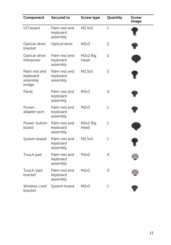
Component Secured to Screw type Quantity Screw image
I/O board Palm rest and keyboard assembly
M2.5x5 1
Optical-drive bracket
Optical drive M2x3 2
Optical-drive interposer
Palm rest and keyboard assembly
M2x2 Big Head
2
Palm rest and keyboard assembly bridge
Palm rest and keyboard assembly
M2.5x5 2
Panel Palm rest and keyboard assembly
M2x3 4
Power-adapter port
Palm rest and keyboard assembly
M2x3 1
Power-button board
Palm rest and keyboard assembly
M2x2 Big Head
1
System board Palm rest and keyboard assembly
M2.5x5 1
Touch pad Palm rest and keyboard assembly
M2x2 4
Touch-pad bracket
Palm rest and keyboard assembly
M2x2 3
Wireless-card bracket
System board M2x3 1
13

After working inside your computer
CAUTION: Leaving stray or loose screws inside your computer may severely damage your computer.
1 Replace all screws and ensure that no stray screws remain inside your computer.
2 Connect any external devices, peripherals, or cables you removed before working on your computer.
3 Replace any media cards, discs, or any other parts that you removed before working on your computer.
4 Connect your computer and all attached devices to their electrical outlets.
5 Turn on your computer.
14
Removing the optical driveWARNING: Before working inside your computer, read the safety information that shipped with your computer and follow the steps in Before working inside your computer. After working inside your computer, follow the instructions in After working inside your computer. For more safety best practices, see the Regulatory Compliance home page at www.dell.com/regulatory_compliance.
Procedure
1 Remove the screw that secures the optical-drive assembly to the base cover.
2 Using a plastic scribe, push the optical drive through the screw hole to release the optical-drive assembly.
15

3 Slide the optical-drive assembly out of the optical-drive bay.
1 optical-drive assembly 2 M2x4 screw
3 plastic scribe 4 base cover
4 Remove the screws that secure the optical-drive bracket to the optical drive.
16
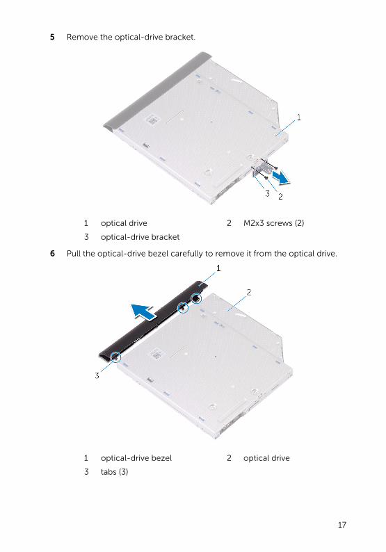
5 Remove the optical-drive bracket.
1 optical drive 2 M2x3 screws (2)
3 optical-drive bracket
6 Pull the optical-drive bezel carefully to remove it from the optical drive.
1 optical-drive bezel 2 optical drive
3 tabs (3)
17

Replacing the optical driveWARNING: Before working inside your computer, read the safety information that shipped with your computer and follow the steps in Before working inside your computer. After working inside your computer, follow the instructions in After working inside your computer. For more safety best practices, see the Regulatory Compliance home page at www.dell.com/regulatory_compliance.
Procedure
1 Align the tabs on the optical-drive bezel with the slots on the optical drive and snap the optical-drive bezel into place.
2 Align the screw holes on the optical-drive bracket with the screw holes on the optical drive.
3 Replace the screws that secure the optical-drive bracket to the optical drive.
4 Slide the optical-drive assembly into the optical-drive bay.
5 Align the screw hole on the optical-drive bracket with the screw hole on the base cover.
6 Replace the screw that secures the optical-drive assembly to the base cover.
18

Removing the base coverWARNING: Before working inside your computer, read the safety information that shipped with your computer and follow the steps in Before working inside your computer. After working inside your computer, follow the instructions in After working inside your computer. For more safety best practices, see the Regulatory Compliance home page at www.dell.com/regulatory_compliance.
Prerequisites
Remove the optical drive.
19

Procedure
1 Remove the screws that secure the base cover to the palm rest and keyboard assembly.
1 M2.5x8 screws (13) 2 M2x2 screws (3)
3 M2x4 screw 4 base cover
2 Using a plastic scribe, pry the base cover starting from the top-left corner of the computer base.
20
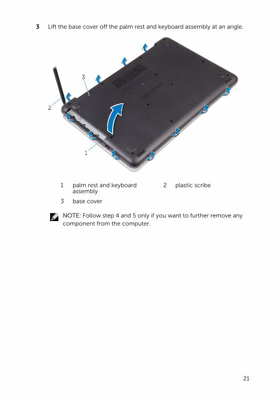
3 Lift the base cover off the palm rest and keyboard assembly at an angle.
1 palm rest and keyboard assembly
2 plastic scribe
3 base cover
NOTE: Follow step 4 and 5 only if you want to further remove any component from the computer.
21

4 Disconnect the battery cable from the system board.
1 battery cable 2 system board
5 Press and hold the power button for 5 seconds to ground the system board.
22

Replacing the base coverWARNING: Before working inside your computer, read the safety information that shipped with your computer and follow the steps in Before working inside your computer. After working inside your computer, follow the instructions in After working inside your computer. For more safety best practices, see the Regulatory Compliance home page at www.dell.com/regulatory_compliance.
Procedure
1 Connect the battery cable to the system board, if applicable.
2 Place the base cover on the palm rest and keyboard assembly and snap the base cover into place.
3 Replace the screws that secure the base cover to the palm rest and keyboard assembly.
Post-requisites
Replace the optical drive.
23
Removing the memory modules
WARNING: Before working inside your computer, read the safety information that shipped with your computer and follow the steps in Before working inside your computer. After working inside your computer, follow the instructions in After working inside your computer. For more safety best practices, see the Regulatory Compliance home page at www.dell.com/regulatory_compliance.
Prerequisites
1 Remove the optical drive.
2 Remove the base cover.
Procedure
1 Use your fingertips to carefully spread apart the securing-clips on each end of the memory-module slot until the memory module pops up.
24

2 Remove the memory module from the memory-module slot.
1 securing clips (2) 2 memory module
3 memory-module slot
25

Replacing the memory modules
WARNING: Before working inside your computer, read the safety information that shipped with your computer and follow the steps in Before working inside your computer. After working inside your computer, follow the instructions in After working inside your computer. For more safety best practices, see the Regulatory Compliance home page at www.dell.com/regulatory_compliance.
Procedure
1 Align the notch on the memory module with the tab on the memory-module slot.
26
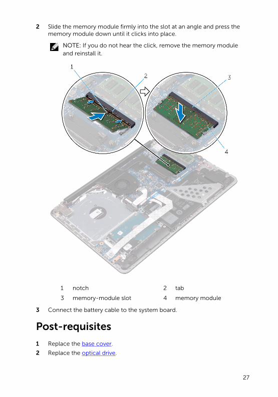
2 Slide the memory module firmly into the slot at an angle and press the memory module down until it clicks into place.
NOTE: If you do not hear the click, remove the memory module and reinstall it.
1 notch 2 tab
3 memory-module slot 4 memory module
3 Connect the battery cable to the system board.
Post-requisites
1 Replace the base cover.
2 Replace the optical drive.
27
Removing the wireless cardWARNING: Before working inside your computer, read the safety information that shipped with your computer and follow the steps in Before working inside your computer. After working inside your computer, follow the instructions in After working inside your computer. For more safety best practices, see the Regulatory Compliance home page at www.dell.com/regulatory_compliance.
Prerequisites
1 Remove the optical drive.
2 Remove the base cover.
Procedure
1 Remove the screw that secures the wireless-card bracket to the system board.
2 Slide and remove the wireless-card bracket and disconnect the antenna cables from the wireless card.
28

3 Slide and remove the wireless card from the wireless-card slot.
1 M2x3 screw 2 wireless-card bracket
3 antenna cables (2) 4 wireless card
5 wireless-card slot
29

Replacing the wireless cardWARNING: Before working inside your computer, read the safety information that shipped with your computer and follow the steps in Before working inside your computer. After working inside your computer, follow the instructions in After working inside your computer. For more safety best practices, see the Regulatory Compliance home page at www.dell.com/regulatory_compliance.
Procedure
CAUTION: To avoid damage to the wireless card, do not place any cables under it.
1 Align the notch on the wireless card with the tab on the wireless-card slot.
2 Insert the wireless card at an angle into the wireless-card slot.
3 Connect the antenna cables to the wireless card.
The following table provides the antenna-cable color scheme for the wireless card supported by your computer.
Connectors on the wireless card Antenna-cable color
Main (white triangle) White
Auxiliary (black triangle) Black
4 Slide and replace the wireless-card bracket on the wireless-card slot.
5 Align the screw hole on the wireless-card bracket with the screw hole on the wireless card and the palm rest and keyboard assembly.
30

6 Replace the screw that secures the wireless-card bracket to the wireless card and the palm rest and keyboard assembly.
1 wireless card 2 notch
3 wireless-card slot 4 tab
5 antenna cables (2) 6 M2x3 screw
7 wireless-card bracket
Post-requisites
1 Replace the base cover.
2 Replace the optical drive.
31
Removing the optical-drive interposer
WARNING: Before working inside your computer, read the safety information that shipped with your computer and follow the steps in Before working inside your computer. After working inside your computer, follow the instructions in After working inside your computer. For more safety best practices, see the Regulatory Compliance home page at www.dell.com/regulatory_compliance.
Prerequisites
1 Remove the optical drive.
2 Remove the base cover.
Procedure
1 Open the latch and disconnect the display cable from the system board.
2 Lift the latch and pull the optical-drive interposer cable from the system board and the optical-drive board connector.
3 Remove the screws that secure the optical-drive interposer to the palm rest and keyboard assembly.
32
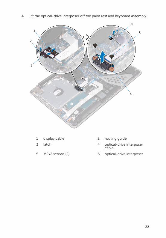
4 Lift the optical-drive interposer off the palm rest and keyboard assembly.
1 display cable 2 routing guide
3 latch 4 optical-drive interposer cable
5 M2x2 screws (2) 6 optical-drive interposer
33
Replacing the optical-drive interposer
WARNING: Before working inside your computer, read the safety information that shipped with your computer and follow the steps in Before working inside your computer. After working inside your computer, follow the instructions in After working inside your computer. For more safety best practices, see the Regulatory Compliance home page at www.dell.com/regulatory_compliance.
Procedure
1 Align the screw holes on the optical-drive interposer with the screw holes on the palm rest and keyboard assembly.
2 Replace the screws that secure the optical-drive interposer to the palm rest and keyboard assembly.
3 Connect the optical-drive interposer cable to the system board and the optical-drive interposer.
4 Insert the optical-drive interposer cable into the latch and press the latch down to secure the cable.
5 Close the latch that secures the optical-drive interposer cable to the system board.
6 Route the display cable through the routing guide and connect it to the system board.
Post-requisites
1 Replace the base cover.
2 Replace the optical drive.
34

Removing the heat-sink assembly
WARNING: Before working inside your computer, read the safety information that shipped with your computer and follow the steps in Before working inside your computer. After working inside your computer, follow the instructions in After working inside your computer. For more safety best practices, see the Regulatory Compliance home page at www.dell.com/regulatory_compliance.
WARNING: The heat sink may become hot during normal operation. Allow sufficient time for the heat sink to cool before you touch it.
CAUTION: For maximum cooling of the processor, do not touch the heat transfer areas on the heat sink. The oils in your skin can reduce the heat transfer capability of the thermal grease.
Prerequisites
1 Remove the optical drive.
2 Remove the base cover.
Procedure
1 Disconnect the fan cable from the system board.
2 In sequential order (as indicated on the heat-sink assembly), loosen the captive screws that secure the heat-sink assembly to the system board.
3 Remove the screws that secure the heat-sink assembly to the system board.
35
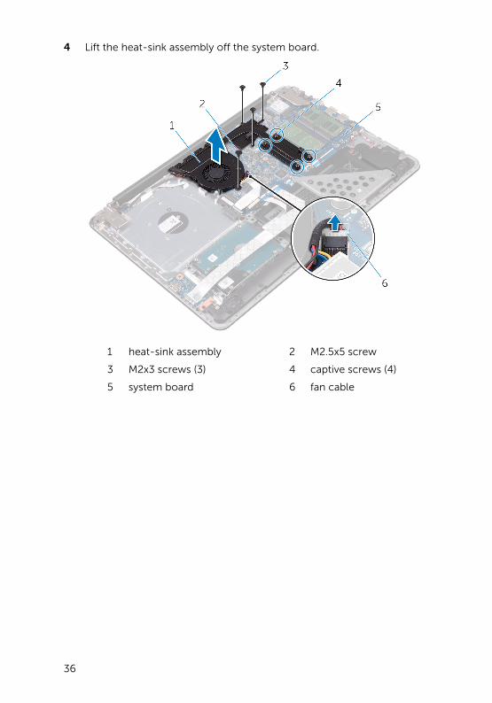
4 Lift the heat-sink assembly off the system board.
1 heat-sink assembly 2 M2.5x5 screw
3 M2x3 screws (3) 4 captive screws (4)
5 system board 6 fan cable
36

Replacing the heat-sink assembly
WARNING: Before working inside your computer, read the safety information that shipped with your computer and follow the steps in Before working inside your computer. After working inside your computer, follow the instructions in After working inside your computer. For more safety best practices, see the Regulatory Compliance home page at www.dell.com/regulatory_compliance.
CAUTION: Incorrect alignment of the heat sink can damage the system board and processor.
NOTE: The original thermal grease can be reused if the original system board and fan are reinstalled together. If either the system board or the fan is replaced, use the thermal pad provided in the kit to ensure that thermal conductivity is achieved.
Procedure
1 Place the heat-sink assembly on the system board.
2 Align the screw holes on the heat-sink assembly with the screw holes on the system board.
3 Replace the screws that secure the heat-sink assembly to the system board.
4 In sequential order (indicated on the heat-sink assembly), tighten the captive screws that secure the heat-sink assembly to the system board.
5 Connect the fan cable to the system board.
Post-requisites
1 Replace the base cover.
2 Replace the optical drive.
37

Removing the coin-cell battery
WARNING: Before working inside your computer, read the safety information that shipped with your computer and follow the steps in Before working inside your computer. After working inside your computer, follow the instructions in After working inside your computer. For more safety best practices, see the Regulatory Compliance home page at www.dell.com/regulatory_compliance.
CAUTION: Removing the coin-cell battery resets the BIOS setup program’s settings to default. It is recommended that you note the BIOS setup program’s settings before removing the coin-cell battery.
Prerequisites
1 Remove the optical drive.
2 Remove the base cover.
Procedure
1 Disconnect the coin-cell battery cable from the system board.
2 Note the coin-cell battery cable routing on the palm rest and keyboard assembly.
3 Remove the coin-cell battery cable from the routing guide on the palm rest and keyboard assembly.
38

4 Peel off the coin-cell battery from the palm rest and keyboard assembly.
1 system board 2 palm rest and keyboard assembly
3 coin-cell battery cable 4 coin-cell battery
5 routing guide
39

Replacing the coin-cell batteryWARNING: Before working inside your computer, read the safety information that shipped with your computer and follow the steps in Before working inside your computer. After working inside your computer, follow the instructions in After working inside your computer. For more safety best practices, see the Regulatory Compliance home page at www.dell.com/regulatory_compliance.
Procedure
1 Adhere the coin-cell battery to the palm rest and keyboard assembly.
2 Route the coin-cell battery cable through the routing guide on the palm rest and keyboard assembly.
3 Connect the coin-cell battery cable to the system board.
Post-requisites
1 Replace the base cover.
2 Replace the optical drive.
40

Removing the I/O boardWARNING: Before working inside your computer, read the safety information that shipped with your computer and follow the steps in Before working inside your computer. After working inside your computer, follow the instructions in After working inside your computer. For more safety best practices, see the Regulatory Compliance home page at www.dell.com/regulatory_compliance.
Prerequisites
1 Remove the optical drive.
2 Remove the base cover.
Procedure
1 Lift the latch and using the pull tab disconnect the I/O-board cable from the system board.
2 Remove the screw that secures the I/O board to the palm rest and keyboard assembly.
41
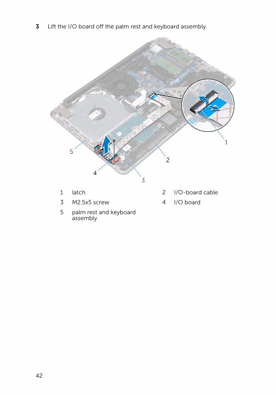
3 Lift the I/O board off the palm rest and keyboard assembly.
1 latch 2 I/O-board cable
3 M2.5x5 screw 4 I/O board
5 palm rest and keyboard assembly
42
Replacing the I/O boardWARNING: Before working inside your computer, read the safety information that shipped with your computer and follow the steps in Before working inside your computer. After working inside your computer, follow the instructions in After working inside your computer. For more safety best practices, see the Regulatory Compliance home page at www.dell.com/regulatory_compliance.
Procedure
1 Using the alignment posts, place the I/O board on the palm rest and keyboard assembly.
2 Align the screw hole on the I/O board with the screw hole on the palm rest and keyboard assembly.
3 Replace the screw that secures the I/O board to the palm rest and keyboard assembly.
4 Connect the I/O board-cable to the system board and close the latch to secure the cable.
Post-requisites
1 Replace the base cover.
2 Replace the optical drive.
43

Removing the hard driveWARNING: Before working inside your computer, read the safety information that shipped with your computer and follow the steps in Before working inside your computer. After working inside your computer, follow the instructions in After working inside your computer. For more safety best practices, see the Regulatory Compliance home page at www.dell.com/regulatory_compliance.
CAUTION: Hard drives are fragile. Exercise care when handling the hard drive.
CAUTION: To avoid data loss, do not remove the hard drive while the computer is in sleep or on state.
Prerequisites
1 Remove the optical drive.
2 Remove the base cover.
3 Remove the I/O board.
Procedure
1 Lift the latch and using the pull tab, disconnect the hard-drive cable from the system board.
2 Remove the screws that secure the hard-drive assembly to the palm rest and keyboard assembly.
44
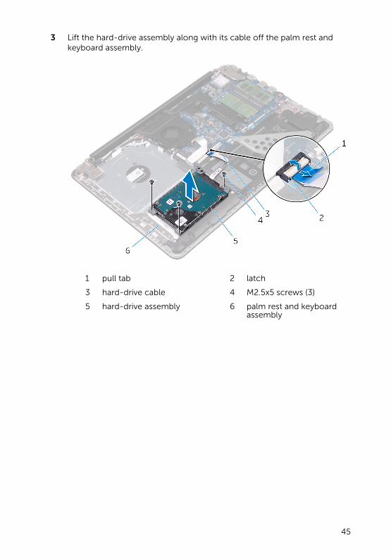
3 Lift the hard-drive assembly along with its cable off the palm rest and keyboard assembly.
1 pull tab 2 latch
3 hard-drive cable 4 M2.5x5 screws (3)
5 hard-drive assembly 6 palm rest and keyboard assembly
45

4 Disconnect the interposer from the hard-drive assembly.
1 hard-drive assembly 2 interposer
5 Remove the screws that secure the hard-drive bracket to the hard drive.
6 Lift the hard drive off the hard-drive bracket.
1 M3x3 screws (4) 2 hard-drive bracket
3 hard drive
46
Replacing the hard driveWARNING: Before working inside your computer, read the safety information that shipped with your computer and follow the steps in Before working inside your computer. After working inside your computer, follow the instructions in After working inside your computer. For more safety best practices, see the Regulatory Compliance home page at www.dell.com/regulatory_compliance.
CAUTION: Hard drives are fragile. Exercise care when handling the hard drive.
Procedure
1 Align the screw holes on the hard-drive bracket with the screw holes on the hard drive.
2 Replace the screws that secure the hard-drive bracket to the hard drive.
3 Connect the interposer to the hard-drive assembly.
4 Align the screw holes on the hard-drive assembly with the screw holes on the palm rest and keyboard assembly.
5 Replace the screws that secure the hard-drive assembly to the palm rest and keyboard assembly.
6 Connect the hard-drive cable to the system board and close the latch to secure the cable.
Post-requisites
1 Replace the I/O board.
2 Replace the base cover.
3 Replace the optical drive.
47

Removing the batteryWARNING: Before working inside your computer, read the safety information that shipped with your computer and follow the steps in Before working inside your computer. After working inside your computer, follow the instructions in After working inside your computer. For more safety best practices, see the Regulatory Compliance home page at www.dell.com/regulatory_compliance.
Prerequisites
1 Remove the optical drive.
2 Remove the base cover.
3 Remove the I/O board.
4 Remove the hard drive.
Procedure
1 Remove the screws that secure the battery bracket to the system board and palm rest and keyboard assembly.
48

2 Lift and remove the battery bracket.
1 system board 2 M2.5x5 screws (2)
3 battery bracket 4 battery
5 palm rest and keyboard assembly
3 Remove the screw that secures the battery to the palm rest and keyboard assembly.
NOTE: Note the location of the screw that secures the battery to the palm rest and keyboard assembly.
49
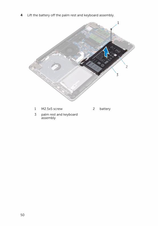
4 Lift the battery off the palm rest and keyboard assembly.
1 M2.5x5 screw 2 battery
3 palm rest and keyboard assembly
50
Replacing the batteryWARNING: Before working inside your computer, read the safety information that shipped with your computer and follow the steps in Before working inside your computer. After working inside your computer, follow the instructions in After working inside your computer. For more safety best practices, see the Regulatory Compliance home page at www.dell.com/regulatory_compliance.
Procedure
1 Align the screw holes on the battery with the screw holes on the palm rest and keyboard assembly.
2 Replace the screw that secures the battery to the palm rest and keyboard assembly.
3 Align the screw holes on the battery bracket with the screw holes on the system board and palm rest and keyboard assembly.
4 Replace the screws that secure the battery bracket to the system board and palm rest and keyboard assembly.
Post-requisites
1 Replace the hard drive.
2 Replace the I/O board.
3 Replace the base cover.
4 Replace the optical drive.
51

Removing the status-light board
WARNING: Before working inside your computer, read the safety information that shipped with your computer and follow the steps in Before working inside your computer. After working inside your computer, follow the instructions in After working inside your computer. For more safety best practices, see the Regulatory Compliance home page at www.dell.com/regulatory_compliance.
Prerequisites
1 Remove the optical drive.
2 Remove the base cover.
3 Remove the I/O board.
4 Remove the hard drive.
5 Remove the battery.
Procedure
1 Open the latch and disconnect the status-light board cable from the system board.
2 Peel off the status-light board cable from the palm rest and keyboard assembly.
3 Push the tab that secures the status-light board to the palm rest and keyboard assembly.
52

4 Lift the status-light board along with its cable off the palm rest and keyboard assembly.
1 system board 2 latch
3 palm rest and keyboard assembly
4 touch-pad bracket
5 tab 6 status-light board
7 status-light board cable
53

Replacing the status-light board
WARNING: Before working inside your computer, read the safety information that shipped with your computer and follow the steps in Before working inside your computer. After working inside your computer, follow the instructions in After working inside your computer. For more safety best practices, see the Regulatory Compliance home page at www.dell.com/regulatory_compliance.
Procedure
1 Place the status-light board into the slot on the palm rest and keyboard assembly.
2 Press down the status-light board until it snaps into place.
3 Adhere the status-light board cable to the palm rest and keyboard assembly.
4 Slide the status-light board cable into the connector on the system board and close the latch to secure the cable.
Post-requisites
1 Replace the battery.
2 Replace the hard drive.
3 Replace the I/O board.
4 Replace the base cover.
5 Replace the optical drive.
54

Removing the speakersWARNING: Before working inside your computer, read the safety information that shipped with your computer and follow the steps in Before working inside your computer. After working inside your computer, follow the instructions in After working inside your computer. For more safety best practices, see the Regulatory Compliance home page at www.dell.com/regulatory_compliance.
Prerequisites
1 Remove the optical drive.
2 Remove the base cover.
3 Remove the I/O board.
4 Remove the hard drive.
5 Remove the battery.
Procedure
1 Open the latch and disconnect the status-light board cable from the system board.
2 Disconnect the speaker cable from the system board.
3 Remove the speaker cable from the routing guides on the palm rest and keyboard assembly.
55
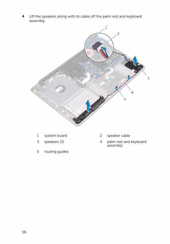
4 Lift the speakers along with its cable off the palm rest and keyboard assembly.
1 system board 2 speaker cable
3 speakers (2) 4 palm rest and keyboard assembly
5 routing guides
56

Replacing the speakersWARNING: Before working inside your computer, read the safety information that shipped with your computer and follow the steps in Before working inside your computer. After working inside your computer, follow the instructions in After working inside your computer. For more safety best practices, see the Regulatory Compliance home page at www.dell.com/regulatory_compliance.
Procedure
1 Using the alignment posts, place the speakers in the slots on the palm rest and keyboard assembly and snap the speakers into place.
2 Route the speaker cable through the routing guides on the palm rest and keyboard assembly.
NOTE: Push the rubber gourmets inside if it pops out while replacing the speakers.
3 Connect the speaker cable to the system board.
4 Slide the status-light board cable into the connector on the system board and close the latch to secure the cable.
Post-requisites
1 Replace the battery.
2 Replace the hard drive.
3 Replace the I/O board.
4 Replace the base cover.
5 Replace the optical drive.
57

Removing the system boardWARNING: Before working inside your computer, read the safety information that shipped with your computer and follow the steps in Before working inside your computer. After working inside your computer, follow the instructions in After working inside your computer. For more safety best practices, see the Regulatory Compliance home page at www.dell.com/regulatory_compliance.
NOTE: Your computer’s Service Tag is stored in the system board. You must enter the Service Tag in the BIOS setup program after you replace the system board.
NOTE: Replacing the system board removes any changes you have made to the BIOS using the BIOS setup program. You must make the appropriate changes again after you replace the system board.
NOTE: Before disconnecting the cables from the system board, note the location of the connectors so that you can reconnect the cables correctly after you replace the system board.
Prerequisites
1 Remove the optical drive.
2 Remove the base cover.
3 Remove the I/O board.
4 Remove the hard drive.
5 Remove the battery.
6 Remove the memory modules.
7 Remove the wireless card.
8 Remove the heat-sink assembly.
Procedure
1 Remove the screws that secure the right display hinge to the palm rest and keyboard assembly.
58
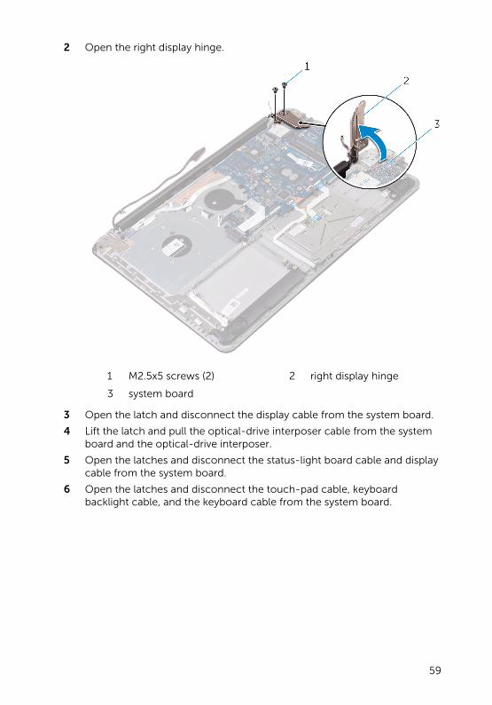
2 Open the right display hinge.
1 M2.5x5 screws (2) 2 right display hinge
3 system board
3 Open the latch and disconnect the display cable from the system board.
4 Lift the latch and pull the optical-drive interposer cable from the system board and the optical-drive interposer.
5 Open the latches and disconnect the status-light board cable and display cable from the system board.
6 Open the latches and disconnect the touch-pad cable, keyboard backlight cable, and the keyboard cable from the system board.
59
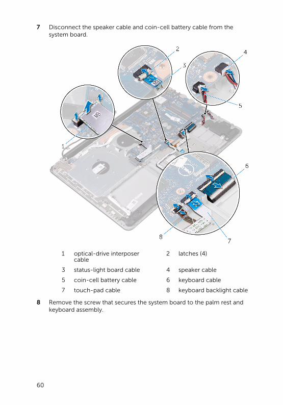
7 Disconnect the speaker cable and coin-cell battery cable from the system board.
1 optical-drive interposer cable
2 latches (4)
3 status-light board cable 4 speaker cable
5 coin-cell battery cable 6 keyboard cable
7 touch-pad cable 8 keyboard backlight cable
8 Remove the screw that secures the system board to the palm rest and keyboard assembly.
60

9 Carefully turn the system board over.
1 M2.5x5 screw 2 system board
10 Lift the latch and pull the power-adapter port cable from the system board.
61

11 Disconnect the power-button cable and power-adapter port cable from the system board.
1 power-button cable 2 power-adapter port cable
3 latch 4 system board
62
Replacing the system boardWARNING: Before working inside your computer, read the safety information that shipped with your computer and follow the steps in Before working inside your computer. After working inside your computer, follow the instructions in After working inside your computer. For more safety best practices, see the Regulatory Compliance home page at www.dell.com/regulatory_compliance.
NOTE: Your computer’s Service Tag is stored in the system board. You must enter the Service Tag in the BIOS setup program after you replace the system board.
NOTE: Replacing the system board removes any changes you have made to the BIOS using the BIOS setup program. You must make the appropriate changes again after you replace the system board.
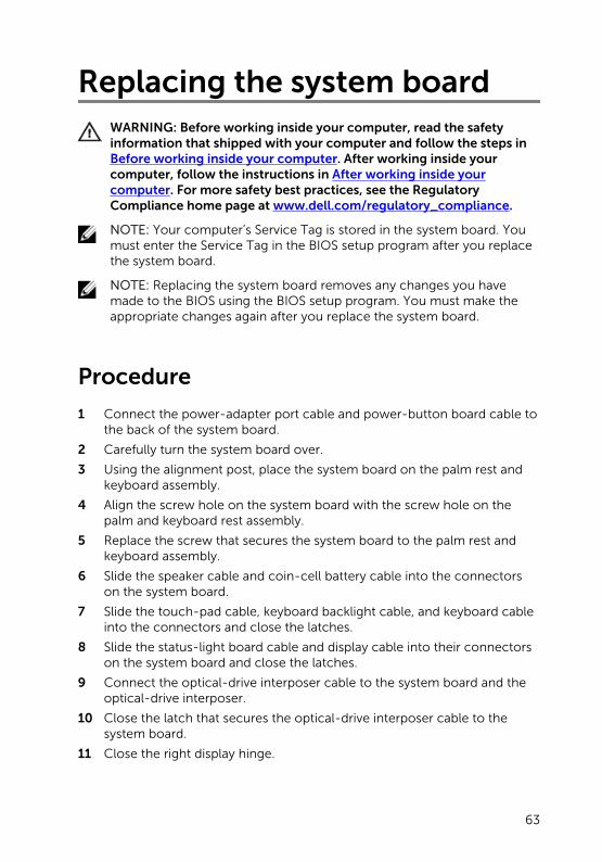
Procedure
1 Connect the power-adapter port cable and power-button board cable to the back of the system board.
2 Carefully turn the system board over.
3 Using the alignment post, place the system board on the palm rest and keyboard assembly.
4 Align the screw hole on the system board with the screw hole on the palm and keyboard rest assembly.
5 Replace the screw that secures the system board to the palm rest and keyboard assembly.
6 Slide the speaker cable and coin-cell battery cable into the connectors on the system board.
7 Slide the touch-pad cable, keyboard backlight cable, and keyboard cable into the connectors and close the latches.
8 Slide the status-light board cable and display cable into their connectors on the system board and close the latches.
9 Connect the optical-drive interposer cable to the system board and the optical-drive interposer.
10 Close the latch that secures the optical-drive interposer cable to the system board.
11 Close the right display hinge.
63

12 Replace the screws that secure the right display hinge to the palm rest and keyboard assembly.
Post-requisites
1 Replace the heat-sink assembly.
2 Replace the wireless card.
3 Replace the memory modules.
4 Replace the battery.
5 Replace the hard drive.
6 Replace the I/O board.
7 Replace the base cover.
8 Replace the optical drive.
64
Removing the touch padWARNING: Before working inside your computer, read the safety information that shipped with your computer and follow the steps in Before working inside your computer. After working inside your computer, follow the instructions in After working inside your computer. For more safety best practices, see the Regulatory Compliance home page at www.dell.com/regulatory_compliance.
Prerequisites
1 Remove the optical drive.
2 Remove the base cover.
3 Remove the I/O board.
4 Remove the hard drive.
5 Remove the battery.
6 Follow the procedure from step 1 to step 2 in “Removing the status-light board”.
7 Remove the memory modules.
8 Remove the wireless card.
9 Remove the heat-sink assembly.
10 Remove the system board.
Procedure
1 Open the latch and disconnect the keyboard backlight cable from the system board.
2 Peel the status-light board cable and keyboard backlight cable off the touch pad.
65

3 Peel off the tape that secures the touch pad to the palm rest and keyboard assembly.
1 touch-pad cable 2 latch
3 tape 4 touch pad
5 keyboard backlight cable 6 palm rest and keyboard assembly
4 Remove the screws that secure the touch-pad bracket to the palm rest and keyboard assembly.
66

5 Lift the touch-pad bracket off the palm rest and keyboard assembly.
1 M2x2 screws (3) 2 touch-pad bracket
3 touch pad 4 palm rest and keyboard assembly
6 Remove the screws that secure the touch pad to the palm rest and keyboard assembly.
67

7 Lift the touch pad off the palm rest and keyboard assembly.
1 M2x2 screws (4) 2 palm rest and keyboard assembly
3 touch pad
68

Replacing the touch padWARNING: Before working inside your computer, read the safety information that shipped with your computer and follow the steps in Before working inside your computer. After working inside your computer, follow the instructions in After working inside your computer. For more safety best practices, see the Regulatory Compliance home page at www.dell.com/regulatory_compliance.
Procedure
1 Align the screw holes on the touch pad with the screw holes on the palm rest and keyboard assembly.
2 Replace the screws that secure the touch pad to the palm rest and keyboard assembly.
3 Adhere the status-light board cable to the touch pad.
4 Align the screw holes on the touch-pad bracket with the screw holes on the palm rest and keyboard assembly.
5 Replace the screws that secure the touch-pad bracket to the palm rest and keyboard assembly.
6 Adhere the tape that secures the touch pad to the palm rest and keyboard assembly.
7 Slide both ends of the touch-pad cable into their respective connectors and close the latches to secure the cable.
8 Slide the keyboard backlight cable into the connector and close the latch to secure the cable.
Post-requisites
1 Replace the system board.
2 Replace the heat-sink assembly.
3 Replace the wireless card.
4 Replace the memory modules.
5 Follow the procedure from step 3 to step 4 in “Replacing the status-light board”.
6 Replace the battery.
7 Replace the hard drive.
69

8 Replace the I/O board.
9 Replace the base cover.
10 Replace the optical drive.
70
Removing the display assembly
WARNING: Before working inside your computer, read the safety information that shipped with your computer and follow the steps in Before working inside your computer. After working inside your computer, follow the instructions in After working inside your computer. For more safety best practices, see the Regulatory Compliance home page at www.dell.com/regulatory_compliance.
Prerequisites
1 Remove the optical drive.
2 Remove the base cover.
Procedure
1 Remove the battery cable from the system board.
2 Note the display cable routing and remove the cable from its routing guides.
71

3 Lift the latch and disconnect the display cable from the system board.
1 display cable 2 system board
3 latch 4 routing guides
4 Remove the screws that secure the display hinges to the palm rest and keyboard assembly.
72
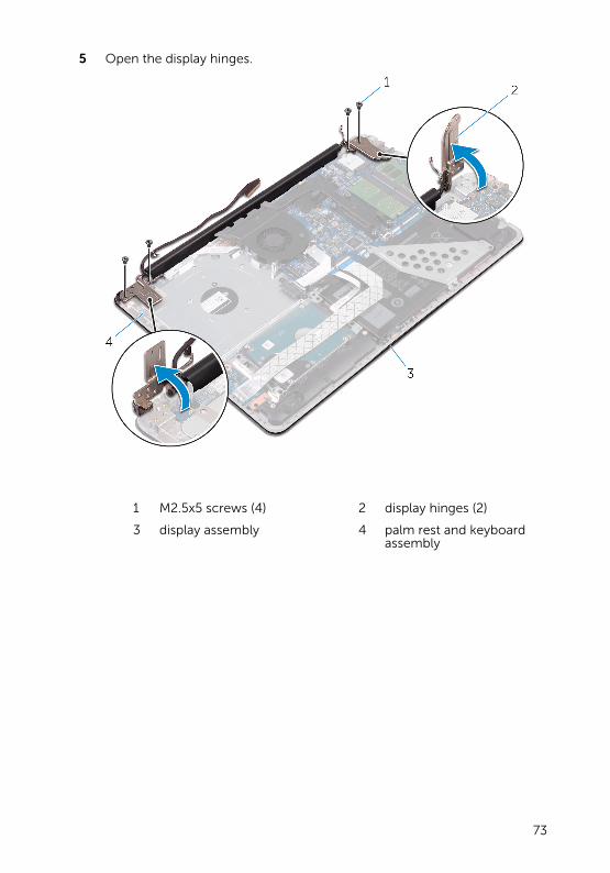
5 Open the display hinges.
1 M2.5x5 screws (4) 2 display hinges (2)
3 display assembly 4 palm rest and keyboard assembly
73

6 Lift the palm rest and keyboard assembly off the display assembly.
1 display hinges (2) 2 palm rest and keyboard assembly
3 display assembly
74
Replacing the display assemblyWARNING: Before working inside your computer, read the safety information that shipped with your computer and follow the steps in Before working inside your computer. After working inside your computer, follow the instructions in After working inside your computer. For more safety best practices, see the Regulatory Compliance home page at www.dell.com/regulatory_compliance.
Procedure
1 Place the palm rest and keyboard assembly on the display assembly.
2 Using the alignment posts, press the display hinges down on the palm rest and keyboard assembly.
3 Replace the screws that secure the display hinges to the palm rest and keyboard assembly.
4 Route the display cable through the routing guides on the palm rest and keyboard.
5 Slide the display cable to the connector on the system board and close the latch to secure the cable.
6 Slide the battery cable to the connector on the system board.
Post-requisites
1 Replace the base cover.
2 Replace the optical drive.
75

Removing the display bezelWARNING: Before working inside your computer, read the safety information that shipped with your computer and follow the steps in Before working inside your computer. After working inside your computer, follow the instructions in After working inside your computer. For more safety best practices, see the Regulatory Compliance home page at www.dell.com/regulatory_compliance.
Prerequisites
1 Remove the optical drive.
2 Remove the base cover.
3 Remove the display assembly.
Procedure
1 Using a plastic scribe, carefully pry up the inside edge of the display bezel.
76

2 Remove the display bezel off the display back-cover.
1 display back-cover 2 display bezel
3 plastic scribe
77

Replacing the display bezelWARNING: Before working inside your computer, read the safety information that shipped with your computer and follow the steps in Before working inside your computer. After working inside your computer, follow the instructions in After working inside your computer. For more safety best practices, see the Regulatory Compliance home page at www.dell.com/regulatory_compliance.
Procedure
Align the display bezel with the display back-cover, and gently snap the display bezel into place.
Post-requisites
1 Replace the display assembly.
2 Replace the base cover.
3 Replace the optical drive.
78

Removing the cameraWARNING: Before working inside your computer, read the safety information that shipped with your computer and follow the steps in Before working inside your computer. After working inside your computer, follow the instructions in After working inside your computer. For more safety best practices, see the Regulatory Compliance home page at www.dell.com/regulatory_compliance.
Prerequisites
1 Remove the optical drive.
2 Remove the base cover.
3 Remove the display assembly.
4 Remove the display bezel.
Procedure
1 Using a plastic scribe, pry the camera module from the display assembly.
2 Lift the camera off the display assembly.
79

3 Disconnect the camera cable from the camera module.
1 plastic scribe 2 camera module
3 camera cable 4 display assembly
80
Replacing the cameraWARNING: Before working inside your computer, read the safety information that shipped with your computer and follow the steps in Before working inside your computer. After working inside your computer, follow the instructions in After working inside your computer. For more safety best practices, see the Regulatory Compliance home page at www.dell.com/regulatory_compliance.
Procedure
1 Connect the camera cable to the camera module.
2 Using the alignment post adhere the camera module on the display assembly and snap it into place.
Post-requisites
1 Replace the display bezel.
2 Replace the display assembly.
3 Replace the base cover.
4 Replace the optical drive.
81

Removing the display panelWARNING: Before working inside your computer, read the safety information that shipped with your computer and follow the steps in Before working inside your computer. After working inside your computer, follow the instructions in After working inside your computer. For more safety best practices, see the Regulatory Compliance home page at www.dell.com/regulatory_compliance.
Prerequisites
1 Remove the optical drive.
2 Remove the base cover.
3 Remove the display assembly.
4 Remove the display bezel.
Procedure
1 Remove the screws that secure the display panel to the display back-cover.
82

2 Lift the display panel gently and turn it over.
1 M2x3 screws (4) 2 display panel
3 display back-cover
3 Peel the tape adhering the display cable to the back of the display panel.
4 Lift the latch and disconnect the display cable from the display-panel cable connector.
83

5 Lift the display panel away from the display back-cover.
1 display panel 2 tape
3 display cable 4 display back-cover
5 latch
84

Replacing the display panelWARNING: Before working inside your computer, read the safety information that shipped with your computer and follow the steps in Before working inside your computer. After working inside your computer, follow the instructions in After working inside your computer. For more safety best practices, see the Regulatory Compliance home page at www.dell.com/regulatory_compliance.
Procedure
1 Connect the display cable to the display-panel connector at the back of the display panel.
2 Adhere the tape that secures the display cable to the back of the display panel.
3 Place the display panel gently on the display back-cover.
4 Align the screw holes on the display panel with the screw holes on the display back-cover.
5 Replace the screws that secure the display panel to the display back-cover.
Post-requisites
1 Replace the display bezel.
2 Replace the display assembly.
3 Replace the base cover.
4 Replace the optical drive.
85
Removing the display hingesWARNING: Before working inside your computer, read the safety information that shipped with your computer and follow the steps in Before working inside your computer. After working inside your computer, follow the instructions in After working inside your computer. For more safety best practices, see the Regulatory Compliance home page at www.dell.com/regulatory_compliance.
Prerequisites
1 Remove the optical drive.
2 Remove the base cover.
3 Remove the display assembly.
4 Remove the display bezel.
5 Remove the display panel.
Procedure
1 Remove the screws that secure the display hinges to the display back-cover.
2 Remove the screws that secure the display-hinge brackets to the display back-cover.
86
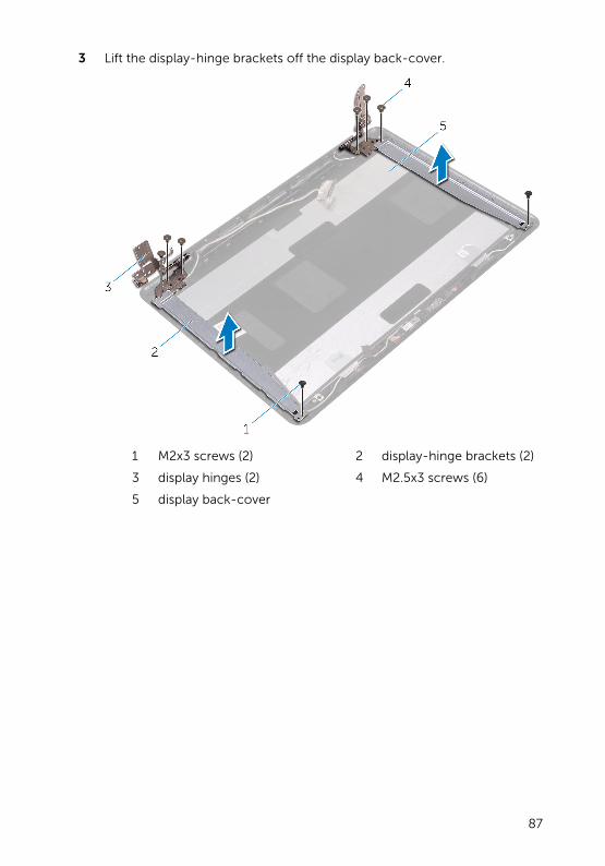
3 Lift the display-hinge brackets off the display back-cover.
1 M2x3 screws (2) 2 display-hinge brackets (2)
3 display hinges (2) 4 M2.5x3 screws (6)
5 display back-cover
87
Replacing the display hingesWARNING: Before working inside your computer, read the safety information that shipped with your computer and follow the steps in Before working inside your computer. After working inside your computer, follow the instructions in After working inside your computer. For more safety best practices, see the Regulatory Compliance home page at www.dell.com/regulatory_compliance.
Procedure
1 Align the screw holes on the display-hinge brackets with the screw holes on the display back-cover.
2 Align the screw holes on the display hinges with the screw holes on the display back-cover.
3 Replace the screws that secure the display hinges to the display back-cover.
Post-requisites
1 Replace the display panel.
2 Replace the display bezel.
3 Replace the display assembly.
4 Replace the base cover.
5 Replace the optical drive.
88

Removing the display cableWARNING: Before working inside your computer, read the safety information that shipped with your computer and follow the steps in Before working inside your computer. After working inside your computer, follow the instructions in After working inside your computer. For more safety best practices, see the Regulatory Compliance home page at www.dell.com/regulatory_compliance.
Prerequisites
1 Remove the optical drive.
2 Remove the base cover.
3 Remove the display assembly.
4 Remove the display bezel.
5 Remove the display panel.
6 Remove the display hinges.
Procedure
1 Disconnect the camera cable from the connector on the camera module.
2 Peel off the tape that secures the camera cable to the display back-cover.
3 Peel off the tape that secures the display cable to the display back-cover.
89

4 Note the display cable routing and remove the display cable from the display back-cover.
1 display back-cover 2 display cable
3 tapes (2) 4 camera module
5 camera cable
90

Replacing the display cableWARNING: Before working inside your computer, read the safety information that shipped with your computer and follow the steps in Before working inside your computer. After working inside your computer, follow the instructions in After working inside your computer. For more safety best practices, see the Regulatory Compliance home page at www.dell.com/regulatory_compliance.
Procedure
1 Route the display cable through the routing guides on the display back-cover.
2 Adhere the tapes that secure the display cable to the display back-cover.
3 Slide the camera cable into the connector on the camera module to secure the cable.
Post-requisites
1 Replace the display hinges.
2 Replace the display panel.
3 Replace the display bezel.
4 Replace the display assembly.
5 Replace the base cover.
6 Replace the optical drive.
91

Removing the display back-cover and antenna assembly
WARNING: Before working inside your computer, read the safety information that shipped with your computer and follow the steps in Before working inside your computer. After working inside your computer, follow the instructions in After working inside your computer. For more safety best practices, see the Regulatory Compliance home page at www.dell.com/regulatory_compliance.
Prerequisites
1 Remove the optical drive.
2 Remove the base cover.
3 Remove the display assembly.
4 Remove the display bezel.
5 Remove the display panel.
6 Remove the display hinges.
7 Remove the display cable.
8 Remove the camera.
Procedure
After performing all the prerequisites, we are left with the display back-cover and antenna assembly.
92
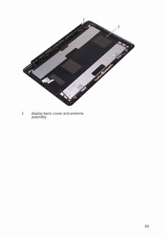
1 display back-cover and antenna assembly
93

Replacing the display back-cover and antenna assembly
WARNING: Before working inside your computer, read the safety information that shipped with your computer and follow the steps in Before working inside your computer. After working inside your computer, follow the instructions in After working inside your computer. For more safety best practices, see the Regulatory Compliance home page at www.dell.com/regulatory_compliance.
Procedure
Place the display back-cover on a flat surface.
Post-requisites
1 Replace the camera.
2 Replace the display cable.
3 Replace the display hinges.
4 Replace the display panel.
5 Replace the display bezel.
6 Replace the display assembly.
7 Replace the base cover.
8 Replace the optical drive.
94

Removing the power-button module
WARNING: Before working inside your computer, read the safety information that shipped with your computer and follow the steps in Before working inside your computer. After working inside your computer, follow the instructions in After working inside your computer. For more safety best practices, see the Regulatory Compliance home page at www.dell.com/regulatory_compliance.
Prerequisites
1 Remove the optical drive.
2 Remove the base cover.
3 Remove the I/O board.
4 Remove the hard drive.
5 Remove the battery.
6 Remove the memory modules.
7 Remove the wireless card.
8 Remove the heat-sink assembly.
9 Remove the system board.
10 Remove the display panel.
Procedure
1 Remove the screw that secures the power-button board to the palm rest and keyboard assembly.
2 Peel off the tape that secures the power-button board to the palm rest and keyboard assembly.
3 Remove the power-button board cable from the routing guides.
95
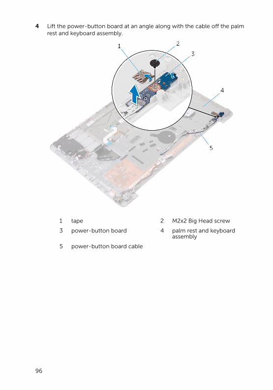
4 Lift the power-button board at an angle along with the cable off the palm rest and keyboard assembly.
1 tape 2 M2x2 Big Head screw
3 power-button board 4 palm rest and keyboard assembly
5 power-button board cable
96
Replacing the power-button module
WARNING: Before working inside your computer, read the safety information that shipped with your computer and follow the steps in Before working inside your computer. After working inside your computer, follow the instructions in After working inside your computer. For more safety best practices, see the Regulatory Compliance home page at www.dell.com/regulatory_compliance.
Procedure
1 Align the screw hole on the power-button board with the screw hole on the palm rest and keyboard assembly.
2 Adhere the power-button board cable to the palm rest and keyboard assembly.
3 Adhere the tape that secures the power-button board to the palm rest and keyboard assembly.
4 Replace the screw that secures the power-button board to the palm rest and keyboard assembly.
Post-requisites
1 Replace the display panel.
2 Replace the system board.
3 Replace the heat-sink assembly.
4 Replace the wireless card.
5 Replace the memory modules.
6 Replace the battery.
7 Replace the hard drive.
8 Replace the I/O board.
9 Replace the base cover.
10 Replace the optical drive.
97

Removing the power-adapter port
WARNING: Before working inside your computer, read the safety information that shipped with your computer and follow the steps in Before working inside your computer. After working inside your computer, follow the instructions in After working inside your computer. For more safety best practices, see the Regulatory Compliance home page at www.dell.com/regulatory_compliance.
Prerequisites
1 Remove the optical drive.
2 Remove the base cover.
3 Remove the I/O board.
4 Remove the hard drive.
5 Remove the battery.
6 Remove the status-light board.
7 Remove the memory modules.
8 Remove the wireless card.
9 Remove the heat-sink assembly.
10 Remove the system board.
11 Remove the display panel.
Procedure
1 Remove the screw that secures the power-adapter port to the palm rest and keyboard assembly.
2 Remove the power-adapter port cable from the routing guides on the palm rest and keyboard assembly.
98
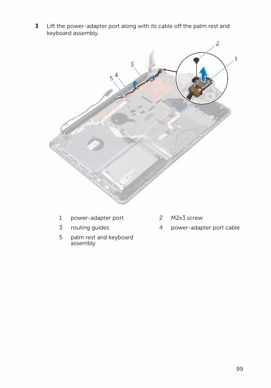
3 Lift the power-adapter port along with its cable off the palm rest and keyboard assembly.
1 power-adapter port 2 M2x3 screw
3 routing guides 4 power-adapter port cable
5 palm rest and keyboard assembly
99
Replacing the power-adapter port
WARNING: Before working inside your computer, read the safety information that shipped with your computer and follow the steps in Before working inside your computer. After working inside your computer, follow the instructions in After working inside your computer. For more safety best practices, see the Regulatory Compliance home page at www.dell.com/regulatory_compliance.
Procedure
1 Place the power-adapter port into the slot on the palm rest and keyboard assembly.
2 Align the screw hole on the power-adapter port with the screw hole on the palm rest and keyboard assembly.
3 Replace the screw that secures the power-adapter port to the palm rest and keyboard assembly.
4 Route the power-adapter port cable through the routing guides on the palm rest and keyboard assembly.
Post-requisites
1 Replace the display panel.
2 Replace the system board.
3 Replace the heat-sink assembly.
4 Replace the wireless card.
5 Replace the memory modules.
6 Replace the status-light board.
7 Replace the battery.
8 Replace the hard drive.
9 Replace the I/O board.
10 Replace the base cover.
11 Replace the optical drive.
100

Removing the palm rest and keyboard assembly
WARNING: Before working inside your computer, read the safety information that shipped with your computer and follow the steps in Before working inside your computer. After working inside your computer, follow the instructions in After working inside your computer. For more safety best practices, see the Regulatory Compliance home page at www.dell.com/regulatory_compliance.
Prerequisites
1 Remove the optical drive.
2 Remove the base cover.
3 Remove the I/O board.
4 Remove the hard drive.
5 Remove the battery.
6 Remove the status-light board.
7 Remove the memory modules.
8 Remove the wireless card.
9 Remove the heat-sink assembly.
10 Remove the coin-cell battery.
11 Remove the system board.
12 Remove the touch pad.
13 Remove the speakers.
14 Remove the display back-cover and antenna assembly.
15 Remove the power-button module.
16 Remove the power-adapter port.
Procedure
After performing the steps in prerequisites, we are left with the palmrest.
101

1 palmrest
102

Replacing the palm rest and keyboard assembly
WARNING: Before working inside your computer, read the safety information that shipped with your computer and follow the steps in Before working inside your computer. After working inside your computer, follow the instructions in After working inside your computer. For more safety best practices, see the Regulatory Compliance home page at www.dell.com/regulatory_compliance.
Procedure
Place the palmrest on a flat surface.
Post-requisites
1 Replace the power-adapter port.
2 Replace the power-button module.
3 Replace the display back-cover and antenna assembly.
4 Replace the speakers.
5 Replace the touch pad.
6 Replace the system board.
7 Replace the coin-cell battery.
8 Replace the heat-sink assembly.
9 Replace the wireless card.
10 Replace the memory modules.
11 Replace the status-light board.
12 Replace the battery.
13 Replace the hard drive.
14 Replace the I/O board.
15 Replace the base cover.
16 Replace the optical drive.
103
System diagnostic lightsPower and battery-status light/hard-drive activity light
Indicates the battery-charge status or the hard-drive activity.
NOTE: Press Fn+H to toggle this light between power and battery-status light and hard-drive activity light.
Hard-drive activity light
Turns on when the computer reads from or writes to the hard drive.
Power and battery-status light
Indicates the power and battery-charge status.
Solid white — Power adapter is connected and the battery has more than 5 percent charge.
Amber — Computer is running on battery and the battery has less than 5 percent charge.
Off
• Power adapter is connected and the battery is fully charged.
• Computer is running on battery and the battery has more than 5 percent charge.
• Computer is in sleep state, hibernation, or turned off.
The power and battery-status light blinks amber along with beep codes indicating failures.
For example, the power and battery-status light blinks amber two times followed by a pause, and then blinks white three times followed by a pause. This 2,3 pattern continues until the computer is turned off indicating no memory or RAM is detected.
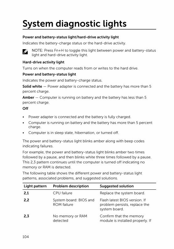
The following table shows the different power and battery-status light patterns, associated problems, and suggested solutions.
Light pattern Problem description Suggested solution
2,1 CPU failure Replace the system board.
2,2 System board: BIOS and ROM failure
Flash latest BIOS version. If problem persists, replace the system board.
2,3 No memory or RAM detected
Confirm that the memory module is installed properly. If
104

Light pattern Problem description Suggested solution
problem persists, replace the memory module.
2,4 Memory or RAM failure Replace the memory module.
2,5 Invalid memory installed Replace the memory module.
2,6 System board or chipset error
Replace the system board.
2,7 LCD failure Replace the LCD.
3,1 CMOS battery failure Replace the CMOS battery.
3,2 PCI or video card or chip failure
Replace the system board.
3,3 Recovery image not found
Reimage the system.
3,4 Recovery image found but invalid
Reimage the system.
Camera status light: Indicates whether the camera is in use.
• Solid white — Camera is in use.
• Off — Camera is not in use.
Caps Lock status light: Indicates whether Caps Lock is enabled or disabled.
• Solid white — Caps Lock enabled.
• Off — Caps Lock disabled.
105

Getting help and contacting Dell
Self-help resources
You can get information and help on Dell products and services using these self-help resources:
Information about Dell products and services
www.dell.com
Dell Help & Support app
Get started app
Accessing help In Windows search, type Help and Support, and press Enter.
Online help for operating system www.dell.com/support/windows
www.dell.com/support/linux
Troubleshooting information, user manuals, setup instructions, product specifications, technical help blogs, drivers, software updates, and so on.
www.dell.com/support
Learn about your operating system, setting up and using your computer, data backup, diagnostics, and so on.
See Me and My Dell at www.dell.com/support/manuals.
Contacting Dell
To contact Dell for sales, technical support, or customer service issues, see www.dell.com/contactdell.
NOTE: Availability varies by country and product, and some services may not be available in your country.
106

NOTE: If you do not have an active internet connection, you can find contact information on your purchase invoice, packing slip, bill, or Dell product catalog.
107