inrush for transformers · 2016-03-30 · 9 transformers - volts and fluxes power off volts flux...
TRANSCRIPT
2
Inrush...
For transformers:The saturation current that can occur when transformers are first switched into service.
Why Important?Fuse coordination work
3
Topics
• The B-H Curve and Remnance
• Transformers - Volts and Fluxes
• Air Core Inductance
• Peak First Half Cycle Current/Considerations
• The Transient Consideration
• Milestones - ESP 0.1 Second
• Medium Voltage Transformer Tables
• Step-Up Transformer Considerations
4
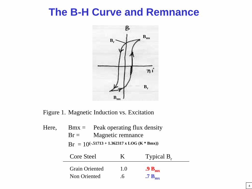
The B-H Curve and Remnance
Figure 1. Magnetic Induction vs. Excitation
Here, Bmx = Peak operating flux densityBr = Magnetic remnanceBr = 10(-.51713 + 1.362317 x LOG (K * Bmx))
Core Steel K Typical Br
Grain Oriented 1.0 .9 Bmx
Non Oriented .6 .7 Bmx
Br
Bmx
Bmx
Br
5
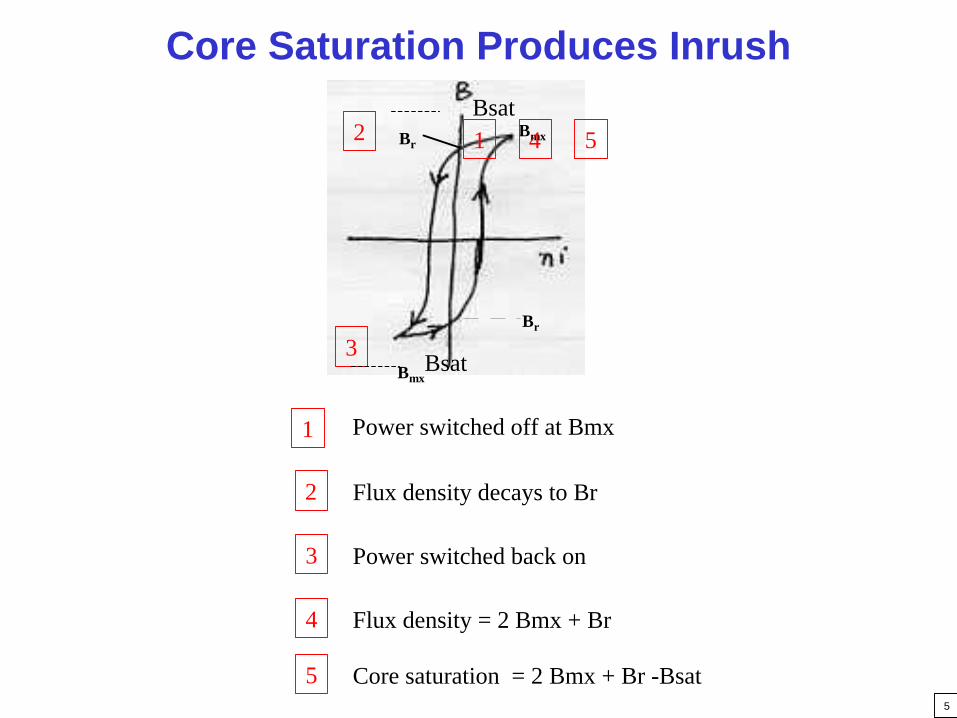
Core Saturation Produces Inrush
1
2
3
Power switched off at Bmx
Flux density decays to Br
Power switched back on
4 Flux density = 2 Bmx + Br
5 Core saturation = 2 Bmx + Br -Bsat
3
2
Bmx
Br
Bsat
BmxBr 1 4 5Bsat
6
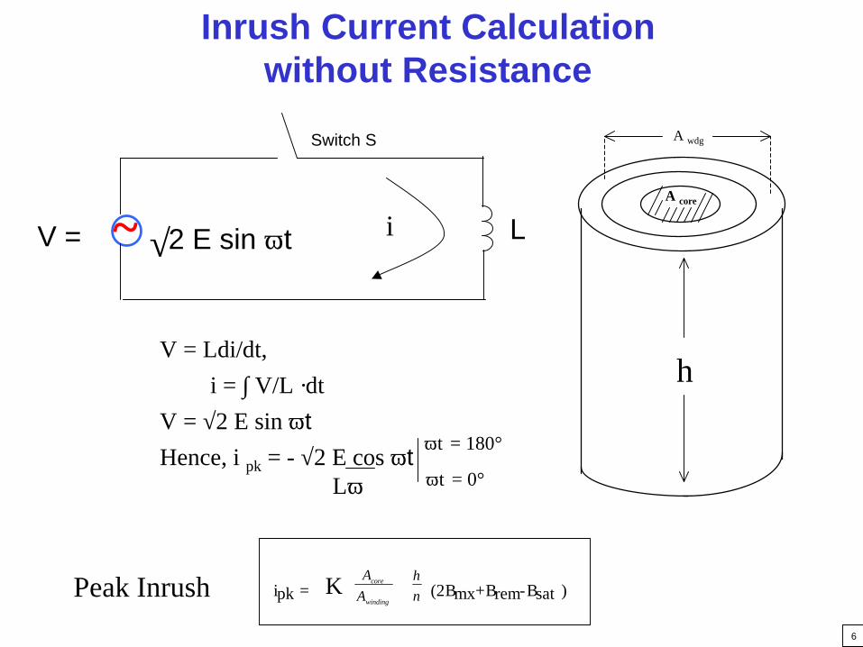
Inrush Current Calculation without Resistance
V = Ldi/dt,
~ 2 E sin ωt√
Switch S
LV = i
∴ i = ∫ V/L ·dtV = √2 E sin ωtHence, i pk = - √2 E cos ωt
ωt = 0°
ωt = 180°
Lω
ipk = A
Acore
winding
h
n
(2 Bmx+ Brem-Bsat )KPeak Inrush
h
A wdg
A core
7
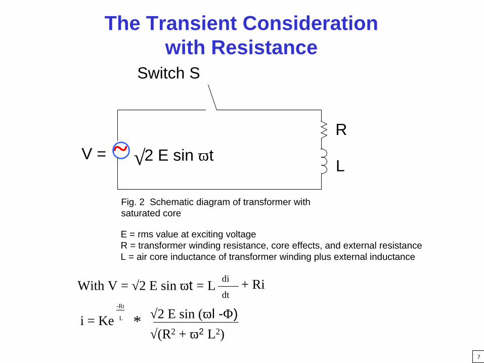
~ 2 E sin ωt√
Switch S
Fig. 2 Schematic diagram of transformer with saturated core
R
L
E = rms value at exciting voltageR = transformer winding resistance, core effects, and external resistanceL = air core inductance of transformer winding plus external inductance
The Transient Consideration with Resistance
V =
With V = √2 E sin ωt = L di
dt+ Ri
√2 E sin (ωl -Φ)-Rt
L
√(R2 + ω2 L2)*i = Ke

8
INRUSH CURRENT V/S ANGLE IN DEG.
-200
0
200
400
600
800
1000
1200
1400
1600
1800
0 90 180 270 360 450 540 630 720 810 900 990 1080
1170
1260
1350
1440
1530
1620
1710
1800
1890
1980
2070
ANGLE IN DEG.
CU
RR
EN
T IN
AM
PS
Damping/Decay Increases with Resistance

9
Transformers - Volts and Fluxes
Power Off
Volts
Flux
Power On
A is the worst phase!
1. If power is turned off at 90°, A is left at peak positive remnance, B at -50%, and C at -50%.
2. When power is switched on again at 0°, Phase A gets full inrush positive i.e. (Br + 2 Bmx) or (~ 2.9 x Bmx), Phase B gets (-.5 Br -1.5 Bmx) or in absolute terms (~2.0 Bmx - 1.2 Bmx), Phase C gets (-.5 Br + .5 Bm). Hence line current into Terminal H1 is drawn by Phase A only, but Phase B also saturates, hence the return path for flux is via air permeability.
3. When Phase B or Phase C are so switched the adjacent phase does not saturate when power is returned.

10
Maximum Line CurrentThe “A” Phase H2 Terminal
IH2 = IH2 - H1 + IH2 - H3
or
IH2 = IA + IB
orIH2 ~ 1.256 * IA
Line current exceeds phase current because (2) phases saturate
11
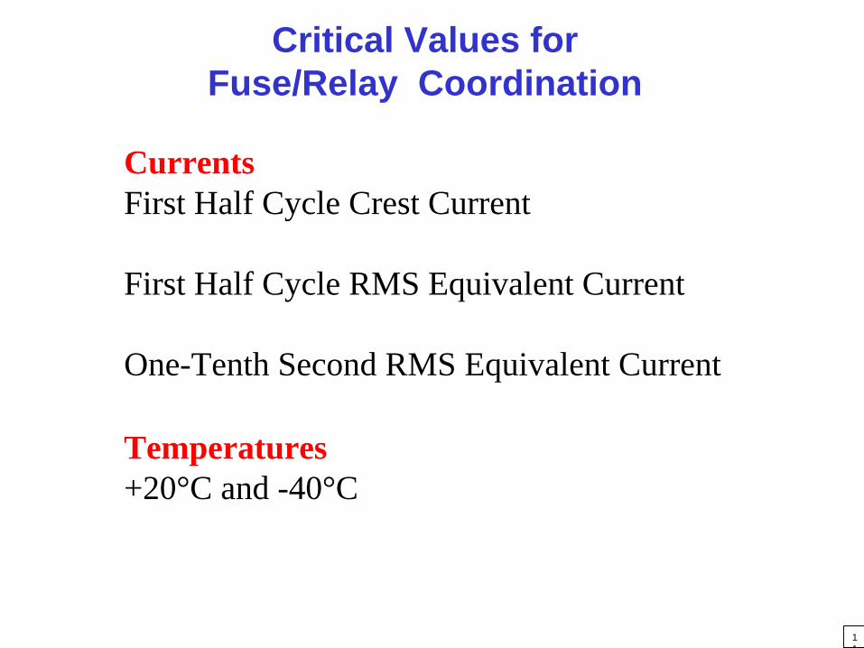
Critical Values for Fuse/Relay Coordination
CurrentsFirst Half Cycle Crest Current
First Half Cycle RMS Equivalent Current
One-Tenth Second RMS Equivalent Current
Temperatures+20°C and -40°C

12
TransformerDamage Curve
Typical Fuse Coordinator ChartLong time 1.25 X N
Fuse Curve
Time(Seconds)
6

13
Transformer Connections
Step-DownDelta Connected Primary
Grounded Y Primary
Step-UpDelta Connected Primary
Grounded Y Primary

14
Approximate Relationships for Inrush with no external impedance
Step-DownDelta Connected Primary
Grounded Y Primary
Step-UpDelta Connected Primary
Grounded Y Primary
Peak Inrush Current100% 19-25 x N
140% 30-35 x N
Peak Inrush Current170% 30-45 x N
250% 50-60 x N

15
Types of Transformers Studied
• Power Cast
• Uni Cast
• Power Dry
• Liquid Filled
16
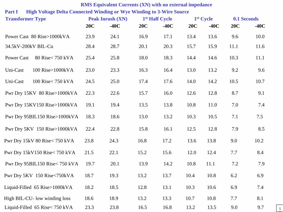
RMS Equivalent Currents (XN) with no external impedancePart I High Voltage Delta Connected Winding or Wye Winding to 3-Wire SourceTransformer Type Peak Inrush (XN) 1st Half Cycle 1st Cycle 0.1 Seconds
20C -40C 20C -40C 20C -40C 20C -40C
Power Cast 80 Rise>1000kVA 23.9 24.1 16.9 17.1 13.4 13.6 9.6 10.0
34.5kV-200kV BIL-Cu 28.4 28.7 20.1 20.3 15.7 15.9 11.1 11.6
Liquid-Filled 65 Rise< 750 kVA 23.3 23.8 16.5 16.8 13.2 13.5 9.0 9.7
Power Cast 80 Rise< 750 kVA 25.4 25.8 18.0 18.3 14.4 14.6 10.3 11.1
Uni-Cast 100 Rise>1000kVA 23.0 23.3 16.3 16.4 13.0 13.2 9.2 9.6
Uni-Cast 100 Rise< 750 kVA 24.5 25.0 17.4 17.6 14.0 14.2 10.5 10.7
Pwr Dry 15KV 80 Rise>1000kVA 22.3 22.6 15.7 16.0 12.6 12.8 8.7 9.1
Pwr Dry 15KV150 Rise>1000kVA 19.1 19.4 13.5 13.8 10.8 11.0 7.0 7.4
Pwr Dry 95BIL150 Rise>1000kVA 18.3 18.6 13.0 13.2 10.3 10.5 7.1 7.5
Pwr Dry 5KV 150 Rise>1000kVA 22.4 22.8 15.8 16.1 12.5 12.8 7.9 8.5
Pwr Dry 15kV 80 Rise< 750 kVA 23.8 24.3 16.8 17.2 13.6 13.8 9.0 10.2
Pwr Dry 15kV150 Rise< 750 kVA 21.5 22.1 15.2 15.6 12.0 12.4 7.7 8.4
Pwr Dry 95BIL150 Rise< 750 kVA 19.7 20.1 13.9 14.2 10.8 11.1 7.2 7.9
Pwr Dry 5KV 150 Rise<750kVA 18.7 19.3 13.2 13.7 10.4 10.8 6.2 6.9
Liquid-Filled 65 Rise>1000kVA 18.2 18.5 12.8 13.1 10.3 10.6 6.9 7.4
High BIL-CU- low winding loss 18.6 18.9 13.2 13.3 10.7 10.8 7.7 8.1
17
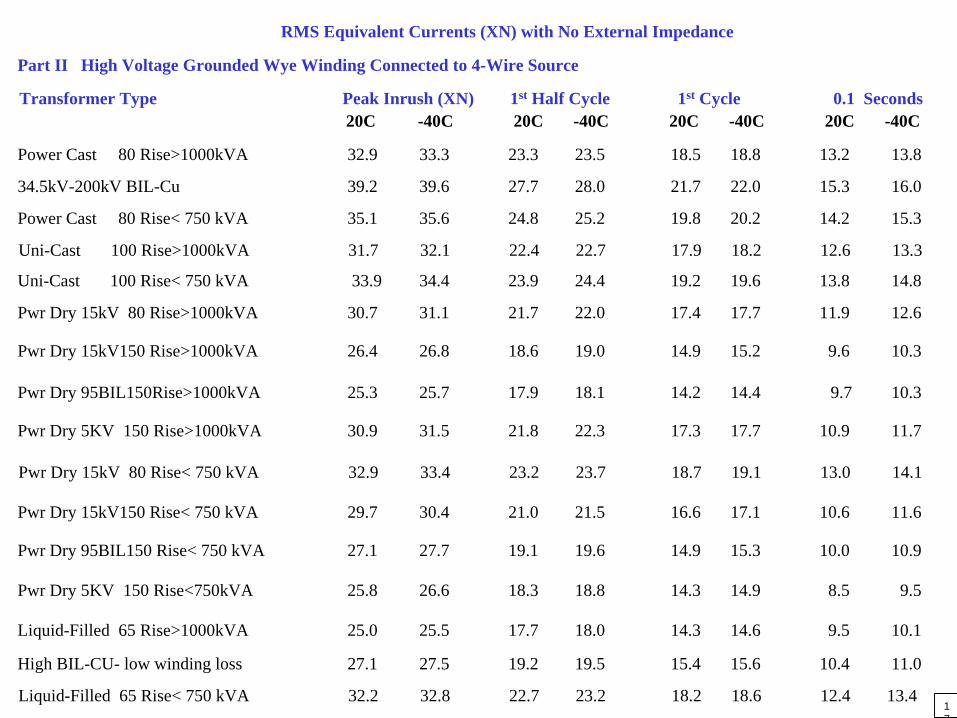
Liquid-Filled 65 Rise< 750 kVA 32.2 32.8 22.7 23.2 18.2 18.6 12.4 13.4
Part II High Voltage Grounded Wye Winding Connected to 4-Wire Source
RMS Equivalent Currents (XN) with No External Impedance
Transformer Type Peak Inrush (XN) 1st Half Cycle 1st Cycle 0.1 Seconds20C -40C 20C -40C 20C -40C 20C -40C
Power Cast 80 Rise>1000kVA 32.9 33.3 23.3 23.5 18.5 18.8 13.2 13.8
34.5kV-200kV BIL-Cu 39.2 39.6 27.7 28.0 21.7 22.0 15.3 16.0
Power Cast 80 Rise< 750 kVA 35.1 35.6 24.8 25.2 19.8 20.2 14.2 15.3
Uni-Cast 100 Rise>1000kVA 31.7 32.1 22.4 22.7 17.9 18.2 12.6 13.3
Uni-Cast 100 Rise< 750 kVA 33.9 34.4 23.9 24.4 19.2 19.6 13.8 14.8
Pwr Dry 15kV 80 Rise>1000kVA 30.7 31.1 21.7 22.0 17.4 17.7 11.9 12.6
Pwr Dry 15kV150 Rise>1000kVA 26.4 26.8 18.6 19.0 14.9 15.2 9.6 10.3
Pwr Dry 95BIL150Rise>1000kVA 25.3 25.7 17.9 18.1 14.2 14.4 9.7 10.3
Pwr Dry 5KV 150 Rise>1000kVA 30.9 31.5 21.8 22.3 17.3 17.7 10.9 11.7
Pwr Dry 15kV 80 Rise< 750 kVA 32.9 33.4 23.2 23.7 18.7 19.1 13.0 14.1
Pwr Dry 15kV150 Rise< 750 kVA 29.7 30.4 21.0 21.5 16.6 17.1 10.6 11.6
Pwr Dry 95BIL150 Rise< 750 kVA 27.1 27.7 19.1 19.6 14.9 15.3 10.0 10.9
Pwr Dry 5KV 150 Rise<750kVA 25.8 26.6 18.3 18.8 14.3 14.9 8.5 9.5
Liquid-Filled 65 Rise>1000kVA 25.0 25.5 17.7 18.0 14.3 14.6 9.5 10.1
High BIL-CU- low winding loss 27.1 27.5 19.2 19.5 15.4 15.6 10.4 11.0
18
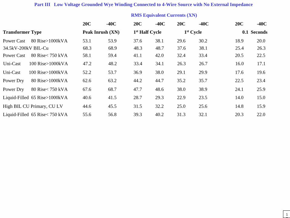
Part III Low Voltage Grounded Wye Winding Connected to 4-Wire Source with No External Impedance
RMS Equivalent Currents (XN)
20C -40C 20C -40C 20C -40C 20C -40C
Transformer Type Peak Inrush (XN) 1st Half Cycle 1st Cycle 0.1 Seconds
Power Cast 80 Rise>1000kVA 53.1 53.9 37.6 38.1 29.6 30.2 18.9 20.034.5kV-200kV BIL-Cu 68.3 68.9 48.3 48.7 37.6 38.1 25.4 26.3Power Cast 80 Rise< 750 kVA 58.1 59.4 41.1 42.0 32.4 33.4 20.5 22.5
Uni-Cast 100 Rise>1000kVA 47.2 48.2 33.4 34.1 26.3 26.7 16.0 17.1
Uni-Cast 100 Rise>1000kVA 52.2 53.7 36.9 38.0 29.1 29.9 17.6 19.6
Power Dry 80 Rise>1000kVA 62.6 63.2 44.2 44.7 35.2 35.7 22.5 23.4
Power Dry 80 Rise< 750 kVA 67.6 68.7 47.7 48.6 38.0 38.9 24.1 25.9
Liquid-Filled 65 Rise>1000kVA 40.6 41.5 28.7 29.3 22.9 23.5 14.0 15.0
High BIL CU Primary, CU LV 44.6 45.5 31.5 32.2 25.0 25.6 14.8 15.9
Liquid-Filled 65 Rise< 750 kVA 55.6 56.8 39.3 40.2 31.3 32.1 20.3 22.0

19
Liquid-Filled 65 Rise< 750 kVA 40.4 41.2 28.5 29.1 22.7 23.3 14.7 16.0
Part IV Low Voltage Delta Connected Winding or Wye Winding Connected to 3-Wire Source with No External Impedance
RMS Equivalent Currents (XN)Transformer Type Peak Inrush (XN) 1st Half Cycle 1st Cycle 0.1 Seconds
20C -40C 20C -40C 20C -40C 20C -40CPower Cast 80 Rise>1000kVA 38.6 39.2 27.3 27.7 21.5 21.9 13.7 14.5
34.5kV-200kV BIL-Cu 49.5 50.0 35.0 35.3 27.3 27.6 18.4 19.1.
Power Cast 80 Rise< 750 kVA 42.1 43.1 29.8 30.5 23.5 24.2 14.9 16.3
Uni-Cast 100 Rise>1000kVA 34.3 35.0 24.6 25.2 19.1 19.4 11.6 12.4
Uni-Cast 100 Rise< 750 kVA 37.8 38.9 27.1 28.0 21.1 21.7 12.8 14.2
Power Dry 80 Rise>1000kVA 45.5 45.9 32.1 32.5 25.6 26.0 16.3 17.0
Power Dry 80 Rise< 750 kVA 49.0 46.8 34.6 35.3 27.6 28.3 18.5 19.8
Liquid-Filled 65 Rise>1000kVA 29.6 30.3 20.9 21.3 16.7 17.1 10.2 10.9
High BIL CU Primary, CU LV 32.3 33.0 22.8 23.3 18.1 18.6 10.8 11.5
20
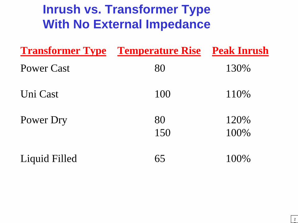
Inrush vs. Transformer Type With No External Impedance
Power Cast 80 130%
Uni Cast 100 110%
Power Dry 80 120%150 100%
Liquid Filled 65 100%
Transformer Type Temperature Rise Peak Inrush
21
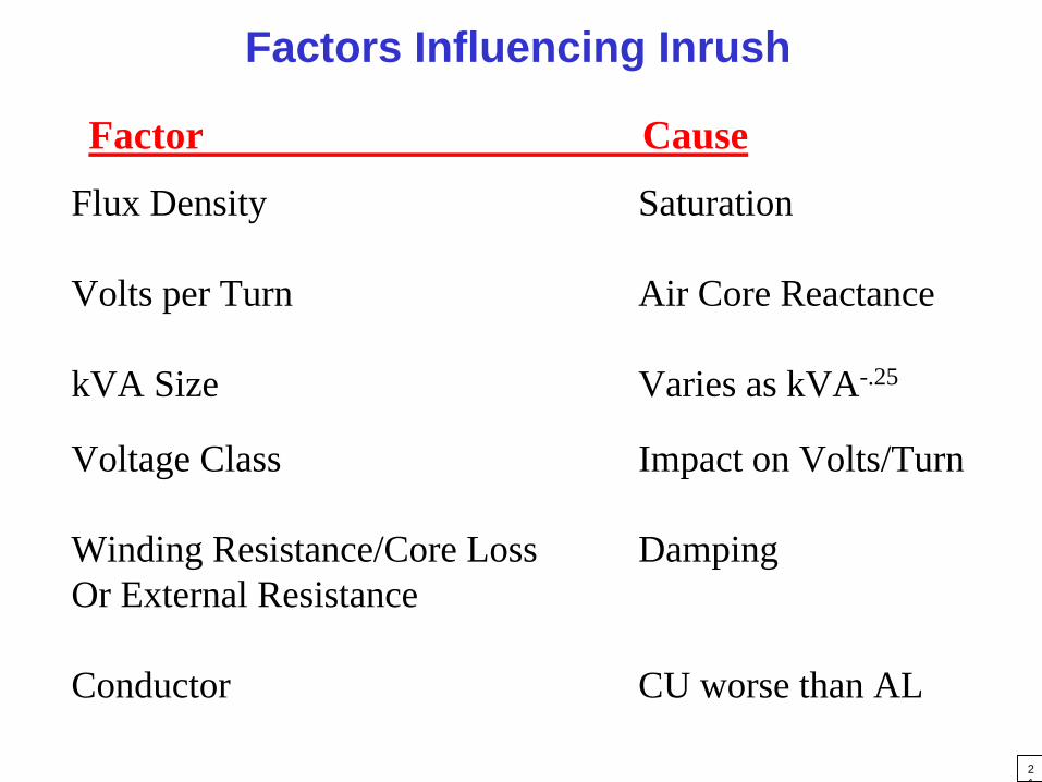
Factors Influencing Inrush
Factor Cause
Flux Density Saturation
Volts per Turn Air Core Reactance
kVA Size Varies as kVA-.25
Voltage Class Impact on Volts/Turn
Winding Resistance/Core Loss DampingOr External Resistance
Conductor CU worse than AL

22
Acknowledgements
Jayant Patwardhan
Transient Computer Program by
Ermal CurdFusing Considerations by
Vanessa Purefoy
Animation and Sound by