inroads v8i templates library creation
TRANSCRIPT

The Template Library InRoads V8i
(Select Series 2)
By— Joe Lukovits

InRoads Procedures for Template Libraries
The Template Library - The Template Library should be stored in the Sub Fold-er for the Individual Highway Alignment. Only Templates, Components and End Con-ditions that are related to the Highway Project should be stored in this .itl file. However, it would be ok for larger project with many Engineers designing the project to have a “Master Template Library” for the project located in the InRoads XM folder. This .itl file would serve as a back-up to the individual Template Libraries for each Highway Alignment. Using the Template Library Organizer, Templates, Components and End Conditions can be copied from one Template Library to another. More on that Later. FORWARD – This Document refers to English Projects. The following directories have been created for your use when copying Templates, Components, End Conditions and Point Names. S:\_Bentley\Msta_V8i\NYSDOT_V8i\Workspace\Projects\ny_common\InRoads Da-ta\nyu_standard.itl and nym_standard.itl
CREATING THE TEMPLATE LIBRARY – Upon accessing the Template Library for the first time in a project the user will note that they have accessed the de-fault Template Library. This Template Library has many useful Components, End Conditions and Templates already created for your use.

It is recommended that the user does not do a “Save As” to create the Project Template Library. Rather, the user should create a new Template Library by doing a file>new>Template Library
3 folders within the Template Library will have to be created. They are as follows: Com-ponents, End Conditions, and Templates. Within each of these folders is where compo-nents, end conditions and templates reside that are only related to the highway alignment we are creating.
The Template Library folders should look like this.
After creation of the Template Library the user shall do a file>save as to the InRoads V8i Folder (Project ###.itl)
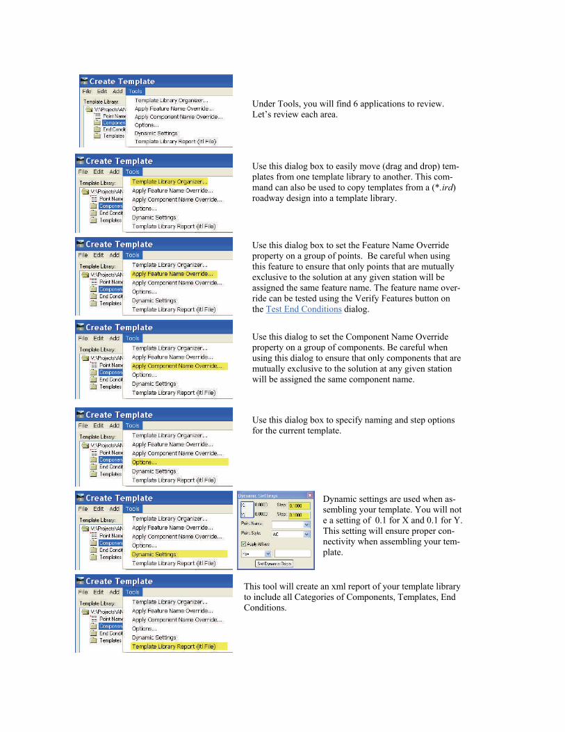
Under Tools, you will find 6 applications to review. Let’s review each area.
Use this dialog box to easily move (drag and drop) tem-plates from one template library to another. This com-mand can also be used to copy templates from a (*.ird) roadway design into a template library.
Use this dialog to set the Component Name Override property on a group of components. Be careful when using this dialog to ensure that only components that are mutually exclusive to the solution at any given station will be assigned the same component name.
Use this dialog box to set the Feature Name Override property on a group of points. Be careful when using this feature to ensure that only points that are mutually exclusive to the solution at any given station will be assigned the same feature name. The feature name over-ride can be tested using the Verify Features button on the Test End Conditions dialog.
Use this dialog box to specify naming and step options for the current template.
Dynamic settings are used when as-sembling your template. You will not e a setting of 0.1 for X and 0.1 for Y. This setting will ensure proper con-nectivity when assembling your tem-plate.
This tool will create an xml report of your template library to include all Categories of Components, Templates, End Conditions.

COMPONENTS – Components are simply “pieces” of a template. Looking at a typical section of a highway section, the components would be the pavement courses, sub grade course, sidewalk, under drain, curb just to name a few. Components are constructed indi-vidually and then pieced together to form a highway section to be used for modeling crea-tion. Let’s take a closer look at a Component.
This component is a 11.0’ long and is a 1 1/2” Pavement course. It has a style assigned to it (XSLFG1_P) which controls the color assigned to it in the Roadway Designer and the display of Cross-Section in Microstation. It is a closed shape with no Parent Component and no display rules and it will be included in the triangulation.

POINT PROPERTIES –Each Component Point has a name and style associated with it. The point has a name, surface feature style and constraints assigned to each point.
You will note the point name is PET (Pavement Edge Travelway), the Surface Feature Style is PET_P and is has two Constraints of Slope at 2.00% and a Horizontal Constraint
By Clicking on Constraints in the Display area and highlighting PET the Constraints will highlight in light blue.

POINTS NAME LIST – A Points Name List has been created to aid you in the design of your templates. The list has been created and resides on the S:\_Bentley\Msta_V8i\NYSDOT_V8i\Workspace\Projects\ny_common\InRoads Da-ta\nyu_standard.itl. The Point Name List file will help you in the design of your template to ensure a consistent name of your points in your template. This is very important when using multiple templates that are transitioning from one template to another.
ACTIVE TEMPLATE— By clicking on Active Template and expanding the Points Folder you will see a list of the points available in the Template. If we select FG_PET infor-mation on the point Display in the Item and Value box. By Double Clicking FG_PET in the Points folder , the Point Properties Box will open.

SURFACE FEATURE STYLE – The surface feature style will be needed to be assigned to each point. The Style has been created in the Style Manager.
The Style has a symbology of PET_P assigned to it. You will note the Level, Color, Line Style, Scale and line weight have been set to NYSDOT standards. When the surface fea-tures are displayed in Microstation, the features will be assigned to the Microstation enti-ty.

CREATE ALTERNATE SURFACE – When checked on an Alternate Surface can be created. An example of this would be creating a DTM of the sub grade. A DTM file name will be needed to be keyed-in for each point in the template that would comprise the Alternate Surface (or Subgrade).
The DTM will be created thru the Roadway Designer providing “Create Alternate Sur-face” is selected prior to running the model. The surface name that it will create depends on the Roadway Corridor Name. An example of this would be as follows: Roadway Corridor Name— (2 LN RAMP.dtm) (This will create the top surface name) Subgrade DTM Name— (2 LN RAMP—Subgrade.dtm)

CONSTRAINTS - Specifies the constraint type: None, Horizontal, Vertical, Slope, Vector-Offset, Project to Surface, Project to Design, Horizontal Maximum, Horizontal Minimum, Vertical Maximum, Vertical Minimum, Angle Distance. Typically, the constraints used in a template would be slope, horizontal and vertical
This point (FG_PET) is constrained in the Slope and Horizontal direction. It’s parent point name is FG_AC and is sloped at 2.0% with a horizontal distance of 11.0’. To change these values, simply edit the values by keying in a new value. The component will update as the values change. Since this component is the top surface of your template the constraints should always be set to Slope and Horizontal distance. Slope is being used to control the Superelevation and horizontal is being used to control the width of the pavement.
By changing the Horizontal Con-straint value to 8.00 the distance will change to 8.0 and follow the Slope Constraint of 2.00%

CONSTRAINT LABEL – The most popular use of a constraint label is used when parametric constraints are used to control horizontal widths of pavement. By using the parametric con-straints the number of templates used in a design can be minimized.
In this example we made a Constraint Label for the Horizontal direction. Note the label name is the same as the Point Name. You may highlight and copy the Point Name to the Constraint Label name. In the Roadway designer we can use the Parametric Constraints to control the pavement width by station. This method eliminates the use of multiple tem-plates for transitions. More on this when we look at the Roadway Designer.

TEMPLATE LIBRARY ORGANIZER – The Template Library Organizer allows the user to copy Components, End Conditions, Templates and Points Name List from one Template Library to another. A CHA default template library has been created for your use. The Template Library has many Components, End Conditions, Templates and Points Name List available for you to copy. Once again it is not recommended that this file be copied to the Project Folder for the use in the Project. Let’s see how the Template Library Organizer works.
In this example the Flyo-ver.itl file was browsed to the “Available in” on the Right. Highlight the desired Compo-nent and drag the Component to the left folder of Compo-
Here is the result of dragging the Template over from Flyover.itl to InRoads Boot Camp.itl Make sure you select YES when prompted.
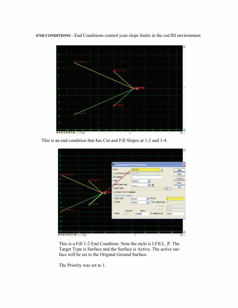
END CONDITIONS – End Conditions control your slope limits in the cut/fill environment
This is an end condition that has Cut and Fill Slopes at 1-2 and 1-4.
This is a Fill 1-2 End Condition. Note the style is LFILL_P. The Target Type is Surface and the Surface is Active. The active sur-face will be set to the Original Ground Surface. The Priority was set to 1.

This point name in this end condition is called FG_LFILL1-2. The feature name over-ride has been clicked-on. This will allow all fills of 1-2 or 1-4 set to a feature name of FILL. This is an option if you would like all of the fills to be continuous in your mod-el. The surface feature style is LFILL_P which will be placed in Microstation V8i un-der the correct level, line weight and linestyle type. Under End Condition Properties, Check for Interception of the Active Surface is checked on, the Place Point at Intersection is checked on and the End Condition is In-finite is checked off. This is checked off because when we test the end condition it will only solve the 1-2 fill slope within 5.00’. After that the end condition will seek a different solution or priority #2 which in this case is FILL1-4.
FG_FILL1-4 has the End Condition is In-finite checked on. So, the fill will be checked first for the 1-2 slope for 5.00’ then 1-4 slope which is infinite. As you can see the fill will have only 2 solutions and will solve provided the original DTM can seek to intersect.

Test your End Condition. Select the test area of your Template. Set your Surface Slope to 10.00%. Drag the line up and down to see your desired results.