„innowacje w procedurach transferu technologii: nauka
TRANSCRIPT
„Innowacje w procedurach transferu technologii: Nauka-Przemysł” Projekt realizowany w ramach programu DIALOG 0047/2016
Akademia Górniczo–Hutnicza Wydział Fizyki i Informatyki Stosowanej al. A. Mickiewicza 30, 30–059 Kraków, tel. +48 12 617 36 14, e–mail: [email protected] www.dialog.agh.edu.pl REGON 000001577, NIP 6750001923
Załącznik 1
Do Zadania nr 5
Usługa doradztwa inżynieryjnego dotyczącego przygotowania laboratorium certyfikacji paneli fotowoltaicznych z modułami krystalicznymi
cienkowarstwowymi oraz procedur krajowych i międzynarodowych obowiązujących w badaniach certyfikacyjnych. Zebranie norm zarówno
krajowych jak i europejskich oraz instytucji certyfikujących.
Kraków 16.12.2018
„Innowacje w procedurach transferu technologii: Nauka-Przemysł”
Projekt realizowany w ramach programu DIALOG 0047/2016
Akademia Górniczo–Hutnicza
Wydział Fizyki i Informatyki Stosowanej
al. A. Mickiewicza 30, 30–059 Kraków,
tel. +48 12 617 36 14,
e–mail: [email protected]
www.dialog.agh.edu.pl
REGON 000001577, NIP 6750001923
USŁUGA DORADZTWA INŻYNIERYJNEGO DOTYCZĄCEGO
PRZYGOTOWANIA LABORATORIUM CERTYFIKACJI PANELI
FOTOWOLTAICZNYCH Z MODUŁAMI KRYSTALICZNYMI
CIENKOWARSTWOWYMI ORAZ PROCEDUR KRAJOWYCH I
MIĘDZYNARODOWYCH OBOWIĄZUJĄCYCH W BADANIACH
CERTYFIKACYJNYCH. ZEBRANIE NORM ZARÓWNO
KRAJOWYCH JAK I EUROPEJSKICH ORAZ INSTYTUCJI
CERTYFIKUJĄCYCH.
JEDNOSTKA OPRACOWYWUJĄCA:
CENTRUM BADAŃ I ROZWOJU
TECHNOLOGII DLA PRZEMYSŁU S.A.
UL. ZŁOTA 59
00-120 WARSZAWA
Kraków, dn. 15.12.2017

2

3
Spis treści
1 Podstawa opracowania ........................................................................................................ 4
2 Zakres opracowania ............................................................................................................. 4
3 Wykaz norm i rozporządzeń ................................................................................................ 5
4 Akredytacja jednostek certyfikujących wyroby .................................................................. 6
5 Wprowadzenie. Certyfikowane laboratoria fotowoltaiczne. ............................................... 7
5.1 Laboratoria certyfikujące zgodnie z normami IEC ..................................................... 7
5.1.1 Program PV Gap ..................................................................................................... 9
5.2 Certyfikowane laboratorium fotowoltaiczne – przykład ........................................... 12
6 Krajowe i europejskie procedury certyfikacji modułów fotowoltaicznych ....................... 15
6.1 Standardy certyfikacji wydajności modułów PV (IEC 61215) ................................. 18
6.1.1 Wykaz aparatury ................................................................................................... 22
6.2 Standardy certyfikacji bezpieczeństwa modułów PV (IEC 61730) .......................... 28
6.2.1 Wykaz aparatury ................................................................................................... 35
6.3 Standardy certyfikacji modułów w korozyjnym środowisku mgły solnej (IEC 61701)
39
7 Bibliografia ........................................................................................................................ 42
8 Spis rysunków ................................................................................................................... 44
9 Spis tabel ........................................................................................................................... 45
10 Załączniki ...................................................................................................................... 46

4
1 Podstawa opracowania
Podstawą opracowania są:
1) Zamówienie nr FIZ/367/Z/2017 z dn. 20.11.2017 r.
2) Umowa usługi nr WFiIS-bu.342-68.68.220.945-7-367/16
2 Zakres opracowania
Usługa doradztwa inżynieryjnego dotyczącego przygotowania laboratorium certyfikacji paneli
fotowoltaicznych z modułami krystalicznymi cienkowarstwowymi oraz procedur krajowych i
międzynarodowych obowiązujących w badaniach certyfikacyjnych. Zebranie norm zarówno
krajowych jak i europejskich (amerykańskiej) oraz instytucji certyfikujących (TUV POLAND).
5
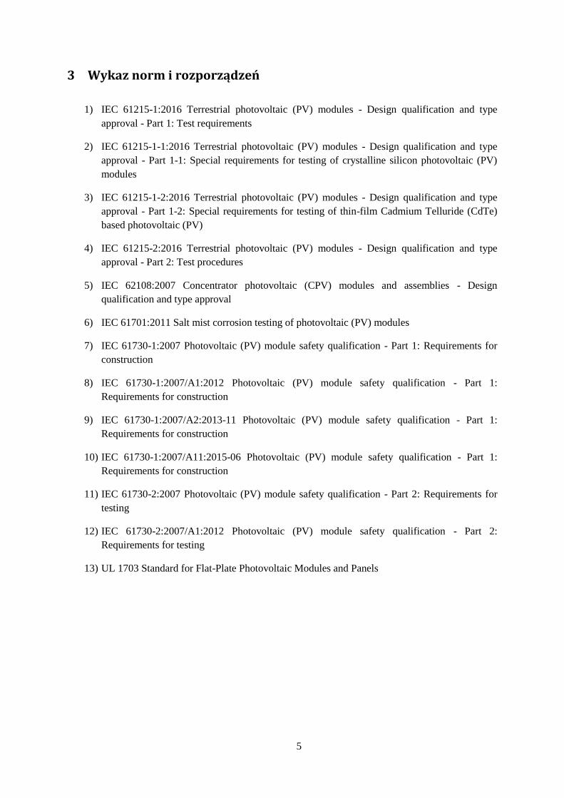
3 Wykaz norm i rozporządzeń
1) IEC 61215-1:2016 Terrestrial photovoltaic (PV) modules - Design qualification and type
approval - Part 1: Test requirements
2) IEC 61215-1-1:2016 Terrestrial photovoltaic (PV) modules - Design qualification and type
approval - Part 1-1: Special requirements for testing of crystalline silicon photovoltaic (PV)
modules
3) IEC 61215-1-2:2016 Terrestrial photovoltaic (PV) modules - Design qualification and type
approval - Part 1-2: Special requirements for testing of thin-film Cadmium Telluride (CdTe)
based photovoltaic (PV)
4) IEC 61215-2:2016 Terrestrial photovoltaic (PV) modules - Design qualification and type
approval - Part 2: Test procedures
5) IEC 62108:2007 Concentrator photovoltaic (CPV) modules and assemblies - Design
qualification and type approval
6) IEC 61701:2011 Salt mist corrosion testing of photovoltaic (PV) modules
7) IEC 61730-1:2007 Photovoltaic (PV) module safety qualification - Part 1: Requirements for
construction
8) IEC 61730-1:2007/A1:2012 Photovoltaic (PV) module safety qualification - Part 1:
Requirements for construction
9) IEC 61730-1:2007/A2:2013-11 Photovoltaic (PV) module safety qualification - Part 1:
Requirements for construction
10) IEC 61730-1:2007/A11:2015-06 Photovoltaic (PV) module safety qualification - Part 1:
Requirements for construction
11) IEC 61730-2:2007 Photovoltaic (PV) module safety qualification - Part 2: Requirements for
testing
12) IEC 61730-2:2007/A1:2012 Photovoltaic (PV) module safety qualification - Part 2:
Requirements for testing
13) UL 1703 Standard for Flat-Plate Photovoltaic Modules and Panels

6
4 Akredytacja jednostek certyfikujących wyroby
Jednostki certyfikujące wyroby, procesy i usługi powinna spełniać wymagania określone w
normie PN-EN ISO/IEC 17065 Ocena zgodności -- Wymagania dla jednostek certyfikujących wyroby,
procesy i usługi. Norma określa wymagania dotyczące kompetencji, spójnego działania oraz
bezstronności jednostek certyfikujących wyroby, procesy i usługi.
Na terenie Kraju ośrodkiem, który dokonuje akredytacji jednostek certyfikujących jest Polskie
Centrum Akredytacji (PCA) prowadząc działalność akredytacyjna na mocy Ustawy z dnia 13 kwietnia
2016 r. o systemach oceny zgodności i nadzoru rynku (Dz. U. 2016 poz. 542). PCA działa zgodnie z
wymaganiami określonymi rozporządzeniu Komisji Europejskiej (WE) 765/2008, w ustawie o
systemach oceny zgodności i nadzoru rynku.
Wdrożenie systemu zarządzania jakością oraz uzyskanie akredytacji od Polskiego Centrum
Akredytacji jest najważniejszym elementem w procesie ubiegania się o uzyskanie statusu
certyfikowanego laboratorium.

7
5 Wprowadzenie. Certyfikowane laboratoria fotowoltaiczne.
Na świecie istnieje wiele laboratoriów spełniających wymogi certyfikacji modułów
fotowoltaicznych. Spośród nich można wyodrębnić laboratoria, które certyfikują moduły
fotowoltaiczne zgodnie z normami amerykańskimi (UL), jak również europejskimi (IEC). Istnieją
również laboratoria, które przeprowadzają certyfikacje zgodnie z obydwoma powyżej przytoczonymi
standardami.
5.1 Laboratoria certyfikujące zgodnie z normami IEC
Organizacja IECEE (IEC System for Conformity Testing and Certification of Electrotechnical
Equipment and Components) tworzy wielostronny system certyfikacji oparty na międzynarodowych
normach IEC do oceny zgodności dla sprzętu i komponentów elektrotechnicznych.
IECEE stworzyła program IECEE-CB, zwany w skrócie CB, który bazuje na zasadzie
wzajemnego uznawania (wzajemnej akceptacji) wyników badań i certyfikatów wydawanych w tym
programie, dla uzyskania certyfikacji na poziomie krajowym.
Schematy IECEE dotyczą m.in. bezpieczeństwa, jakości, wydajności i ogólnej wydajności
komponentów, urządzeń i sprzętu dla domów, biur, warsztatów, zakładów opieki zdrowotnej i innych.
W sumie IECEE obejmuje 23 kategorie sprzętu elektrycznego i elektronicznego oraz usługi testowania
(wśród nich modułu fotowoltaiczne).
Rys. 5.1 Role partnerów w systemie certyfikacji IECEE [24]

8
1) Member Bodies (MB) – Organy członkowskie
Organy członkowskie (MB) są przedstawicielami krajowych społeczności
elektrotechnicznych. W każdym kraju jest tylko jeden MB. Obejmują one szeroką
reprezentację przemysłu, elektrycznych organów regulacyjnych i organów normalizacyjnych,
a także interesy w zakresie oceny zgodności.
Na terytorium Polski jest to Polskie Centrum Badań i Certyfikacji S.A.
2) National Certification Bodies (NCBs) – Krajowe jednostki certyfikujące
Stosują krajowy system certyfikacji lub zatwierdzania urządzeń elektrotechnicznych i
komponentów w krajach, w których znajduje się ciało członkowskie IECEE. Wydają
certyfikaty testów CB.
Na terytorium Polski są to:
Stowarzyszenie Elektryków Polskich. Biuro Badawcze ds. Jakości
Instytut Technologii Elektronowej Oddział PREDOM
Polskie Centrum Badań i Certyfikacji S.A.
3) CB Testing Laboratories (CBTL) – Laboratoria testowe jednostek certyfikujących
Wykonują programy testowe i wydają raporty z testów (TR) dla międzynarodowych norm
IEC. Certyfikaty testowe CB są oparte na TRs.
Associated Testing Laboratories (ACTL) – Powiązane Laboratoria Testowe
Mają ograniczone możliwości testowania i przeprowadzają tylko określone i / lub wybrane
testy z kompletnej procedury testowej wymaganej do wydania TR.
4) Customers' Testing Facilities (CTFs) – Urządzenia testujące klientów
Urządzenia testujące klientów (CTF) są własnością producentów i uczestniczą w systemie
IECEE.
5) Local Technical Representatives (LTRs) – Lokalni przedstawiciele techniczni
Lokalni przedstawiciele techniczni (LTR) to osoby fizyczne, działające na odpowiedzialność
NCBs, które wykonują czynności testowe i / lub nadzorujące lokalnie na CTF.
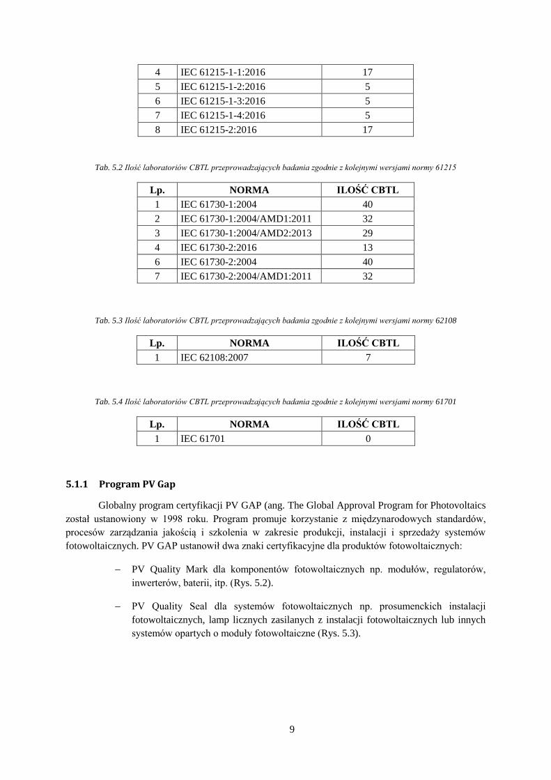
W Tab. 5.1 - Tab. 5.4 zestawiono ilość CBTL, przeprowadzających badania z normami
dotyczących certyfikacji modułów fotowoltaicznych.
Tab. 5.1 Ilość laboratoriów CBTL przeprowadzających badania zgodnie z kolejnymi wersjami normy 61215
Lp. NORMA ILOŚĆ CBTL
1 IEC 61215:2005 39
2 IEC 61215:1993 9
3 IEC 61215-1:2016 17
9
4 IEC 61215-1-1:2016 17
5 IEC 61215-1-2:2016 5
6 IEC 61215-1-3:2016 5
7 IEC 61215-1-4:2016 5
8 IEC 61215-2:2016 17
Tab. 5.2 Ilość laboratoriów CBTL przeprowadzających badania zgodnie z kolejnymi wersjami normy 61215
Lp. NORMA ILOŚĆ CBTL
1 IEC 61730-1:2004 40
2 IEC 61730-1:2004/AMD1:2011 32
3 IEC 61730-1:2004/AMD2:2013 29
4 IEC 61730-2:2016 13
6 IEC 61730-2:2004 40
7 IEC 61730-2:2004/AMD1:2011 32
Tab. 5.3 Ilość laboratoriów CBTL przeprowadzających badania zgodnie z kolejnymi wersjami normy 62108
Lp. NORMA ILOŚĆ CBTL
1 IEC 62108:2007 7
Tab. 5.4 Ilość laboratoriów CBTL przeprowadzających badania zgodnie z kolejnymi wersjami normy 61701
Lp. NORMA ILOŚĆ CBTL
1 IEC 61701 0
5.1.1 Program PV Gap
Globalny program certyfikacji PV GAP (ang. The Global Approval Program for Photovoltaics
został ustanowiony w 1998 roku. Program promuje korzystanie z międzynarodowych standardów,
procesów zarządzania jakością i szkolenia w zakresie produkcji, instalacji i sprzedaży systemów
fotowoltaicznych. PV GAP ustanowił dwa znaki certyfikacyjne dla produktów fotowoltaicznych:
PV Quality Mark dla komponentów fotowoltaicznych np. modułów, regulatorów,
inwerterów, baterii, itp. (Rys. 5.2).
PV Quality Seal dla systemów fotowoltaicznych np. prosumenckich instalacji
fotowoltaicznych, lamp licznych zasilanych z instalacji fotowoltaicznych lub innych
systemów opartych o moduły fotowoltaiczne (Rys. 5.3).

10
Rys. 5.2 PV Quality Mark [27] Rys. 5.3 PV Quality Seal [27]
Od roku 2009 właścicielem programu PV GAP jest IECEE.
Na Rys. 5.4 przedstawiono przebieg procesu certyfikacji w programie PV GAP. Szczegółowe
warunki programu opisano w dokumencie [25] IECEE PV PROGRAM. PROCEDURE FOR
CERTIFICATION OF PHOTOVOLTAIC (PV) PRODUCTS AND THE USE OF THE IECEE PV
QUALITY MARK AND PV QUALITY. SEAL. OD-2051-Ed.1.0. 2010-09-17 stanowiącym
załącznik no niniejszego opracowania.

11
Rys. 5.4 Przebieg procesu certyfikacji w ramach programu PV GAP [27]

12
5.2 Certyfikowane laboratorium fotowoltaiczne – przykład
W niniejszym rozdziale przedstawiono przykład laboratorium fotowoltaicznego Photovoltaik
Institut Berlin.
Photovoltaik Institut Berlin przeprowadza certyfikację modułów fotowoltaicznych m.in. z
następującymi normami: IEC 61215, IE 61730, UL 1703, IEC 61701, IEC 62716, IEC TS 62804-1 i
inne Instytut jest jednostką akredytowaną przez niemieckie centrum akredytacji DAkkS (Die Deutsche
Akkreditierungsstelle GmbH) oraz IECEE poprzez narodowego członka: TUV Süd.
Powierzchnia laboratorium wynosi ponad 2400 m2. Instytut opracował własne procedury
umożliwiające wykonanie pełnego procesu certyfikacji w ciągu trzech miesięcy. W obszernych
komorach klimatycznych możliwe jest równoległe testowanie łącznie 180 modułów fotowoltaicznych.
Zaletą laboratorium jest możliwość wykonania badań certyfikujących zarówno z normami IEC
jak i UL.
Poniżej przedstawiono zdjęcia przedstawiające wyposażenie laboratorium.
Rys. 5.5 Akredytowane laboratorium certyfikacji modułów fotowoltaicznych Photovoltaik Institut Berlin.
Źródło: https://www.pi-berlin.com/prasowy_greenpower_2015.html

13
Rys. 5.6 Armatka z gradem o średnicy maks. 75mm do badania odporności na gradobicie.
Źródło: https://www.pi-berlin.com/prasowy_greenpower_2015.html
Rys. 5.7 Symulator światła słonecznego wykorzysywany do wykonywania testów wydajności modułów.
Źródło: https://www.pi-berlin.com/prasowy_greenpower_2015.html

14
Rys. 5.8 Akredytowane laboratorium certyfikacji modułów fotowoltaicznych Photovoltaik Institut Berlin.
Źródło: https://www.pi-berlin.com/prasowy_greenpower_2015.html
Rys. 5.9 Komora klimatyczna do badania jakości modułu.
Źródło: https://www.pi-berlin.com/prasowy_greenpower_2015.html

15
6 Krajowe i europejskie procedury certyfikacji modułów
fotowoltaicznych
Dynamiczny rozwój branży fotowoltaicznej po 2000 roku spowodował konieczność
stworzenia zbioru norm, które i przepisów, które umożliwią przeprowadzenie spójnego procesu
certyfikacji produktów w postaci modułów fotowoltaicznych.
Na terenie Unii Europejskiej certyfikacja przeprowadzana jest zgodnie z normami
Międzynarodowej Komisji Elektrotechnicznej – IEC (ang. International Electrotechnical Commission)
przedstawionymi poniżej (Tab. 6.1).
Tab. 6.1 Wykaz norm obowiązujących w Polsce i na terenie Unii Europejskiej dotyczący certyfikacji modułów
fotowoltaicznych
Lp. Oznaczenie normy Tytuł
1. IEC 61215-1:2016-01 Terrestrial photovoltaic (PV) modules - Design qualification and type
approval - Part 1: Test requirements
2. IEC 61215-1-1:2016-10
Terrestrial photovoltaic (PV) modules - Design qualification and type
approval - Part 1-1: Special requirements for testing of crystalline
silicon photovoltaic (PV) modules
3. IEC 61215-1-2:2016-07
Terrestrial photovoltaic (PV) modules - Design qualification and type
approval - Part 1-2: Special requirements for testing of thin-film
Cadmium Telluride (CdTe) based photovoltaic (PV)
4. IEC 61215-2:2016-05 Terrestrial photovoltaic (PV) modules - Design qualification and type
approval - Part 2: Test procedures
5. IEC 61730-1:2007 Photovoltaic (PV) module safety qualification - Part 1: Requirements
for construction
6. IEC 61730-1:2007/A1:2012 Photovoltaic (PV) module safety qualification - Part 1: Requirements
for construction
7. IEC 61730-1:2007/A2:2013-11 Photovoltaic (PV) module safety qualification - Part 1: Requirements
for construction
8. IEC 61730-1:2007/A11:2015-06 Photovoltaic (PV) module safety qualification - Part 1: Requirements
for construction
9. IEC 61730-2:2007 Photovoltaic (PV) module safety qualification - Part 2: Requirements
for testing
10. IEC 61730-2:2007/A1:2012 Photovoltaic (PV) module safety qualification - Part 2: Requirements
for testing
11. IEC 62108:2017-02 Concentrator photovoltaic (CPV) modules and assemblies - Design
qualification and type approval
12. IEC 61701:2012 Salt mist corrosion testing of photovoltaic (PV) modules
Zasadniczo, normy przedstawione w powyższej tabeli można podzielić na 4 podgrupy:
16
1) Normy z grupy IEC 61215 dotycząca standardów wydajności modułów PV,
2) Normy z grupy IEC 61730 dotycząca standardów bezpieczeństwa modułów PV,
3) Norma IEC 62108 dotycząca modułów ze skoncentrowanym światłem słonecznym,
4) Norma IEC 61701 dotycząca testowania modułów w korozyjnym środowisku mgły solnej.
Diagram przedstawiający podział norm na grupy przedstawiono na Rys. 6.1.

17
Rys. 6.1 Podział norm dotyczących certyfikacji modułów fotowoltaicznych
Certyfikacja modułów fotowoltaicznych
Wydajność modułów PV
IEC 61215
Moduły PV wykonane z krzemu
krystalicznego
IEC 61215-1-1
Moduły PV wykonane na bazie tellurku
kadmu (CdTe)
IEC 61215-1-2
Moduły PV wykonane na bazie krzemu
amorficznego
IEC 61215-1-3
Moduły PV wykonane na bazie Cu (In, Ga)
(S,Se)2
IEC 61215-1-4
Metody badań
IEC 61215-2
Bezpieczeństwo modułów PV
IEC 61730
Wymagania dotyczące konstrukcji
IEC 61730-1
Wymagania dotyczące badań
IEC 61730-2
Moduły PV ze skoncentrowanym
światłem słonecznym PV
IEC 62108
Testowanie modułów w korozyjnym
środowisku mgły solnej
IEC 61701

18
6.1 Standardy certyfikacji wydajności modułów PV (IEC 61215)
Norma IEC 61215 ustanawia wymagania IEC (International Electrotechnical Commission)
dotyczące kwalifikacji konstrukcji i aprobaty typu dla modułów fotowoltaicznych do zastosowań
naziemnych nadających się do długotrwałej eksploatacji w typowych warunkach klimatycznych
zdefioniowanych w normie IEC 60721-2-1. Zdefiniowane w normie testy określają wydajność
testowanych modułów fotowoltaicznych.
Norma ta ma zastosowanie do wszystkich modułów płaskich wykonanych z moduły z
krzemem krystalicznym, a także do modułów cienkowarstwowych.
Normy IEC 61215 niestosuje się do modułów stosowanych w systemach z koncentratorami
światła, natomiast może być wykorzystana do modułów w układach z niskim stopniem koncentracji
(1 do 3 słońc) wykorzystujących światło rozproszone.
Celem testów opisanych w normie jest wyznaczenie elektrycznych i cieplnych charakterystyk
modułu fotowoltaicznego oraz wykazanie, że wyprodukowany moduł będzie w stanie wytrzymać
wydłużoną ekspozycję w określonych warunkach klimatycznych. [1]
W Tab. 6.2 zebrano warunki testów według określonych w normie [4].

19
Tab. 6.2 Standardy testowania modułów fotowoltaicznych wg. normy IEC 61215-2:2016 [4]
NUMER
TEST
NUMER
TESTU
(61215:2005)
NAZWA TESTU WARUNKI TESTU
MQT 01 10.1 Inspekcja wizualna
Pęknięcia powierzchni zewnętrznych.
Wygięcia lub złe ułożenie elementów (junctionbox, ogniwa, podłoża, pokrycia) wpływające na
wydajność modułu.
Pęcherze lub delaminacje na połączeniach elektrycznych
MQT 02 10.2 Określenie punktu mocy
maksymalnej
Według normy IEC 60904-1. Test zakłada pomiar 4-przewodowy prądu i napięcia (przy końcówkach
kablowych modułu) urządzeniami o dokładności ±0,2%. Regulowana rezystancja obciążenia musi
być w stanie doprowadzić ogniwo do blisko prądu zwarciowego (napięcie na ogniwie poniżej 3%
napięcia rozwarcia). Test wymaga symulatora (klasy BBB) wraz z ogniwem referencyjnym.
Dopuszcza się też pomiar w świetle naturalnym kontrolowanym piranometrem (min 800W/m2, max
1% fluktuacji). Temperatura modułu musi być ustabilizowana w zakresie ±1⁰C (urządzenie z
dokładnością +/- 1⁰C i powtarzalnością +/- 0.5⁰C).
MQT 03 10.3 Test izolacji
Dla modułów o napięciu powyżej 50V: wytrzymałość dielektryczna przy 1000V + dwukrotność
maksymalnego napięcia systemu przez 1 minutę, następnie test izolacji przy 500V lub maksymalnego
napięcia systemu prze 2 minuty.
Dla modułów o napięciu poniżej 50V testy wykonywane są napięciem 500V.
MQT 04 10.4 Pomiar współczynników
temperaturowych
Według normy IEC 60891. Wymagane jest urządzenie do kontrolowania temperatury modułu.
Wykonuje się pomiar charakterystyki I-V (ze źródłem BBB i aparaturą pomiarową zgodną z IEC
60904-1) przy co najmniej pięciu temperaturach na przestrzeni 30⁰C. Temperatura jest mierzona jest
na module w pięciu punktach (środek krótszego boku, środek dłuższego boku, narożnik przeciwległy
do tych boków i środek modułu, wszystkie punkty pod ogniwami krzemowymi).
Dodatkowo norma IEC 60904-10 opisuje jak należy ekstrapolować dane z ww. współczynników.
MQT 05 10.5
Pomiar znamionowej
temperatury pracy
modułu (ang. NMOT –
nominal module
operating temperature)
Moduł pracujący blisko punktu maksymalnej mocy. Całkowita irradiancja 800W/m2. Temperatura
otoczenia 25⁰C. Prędkość wiatru 1m/s.
MQT 06 10.6 Parametry przy
warunkach STC i NMOT
Temperatura przy STC i NMOT. Irradiancja 1000W/m2 oraz 800W/m2 zgodne ze spektrum
przewidzianym przez IEC 60904-3. Norma zawiera szczegółowy tabelaryczny opis spectrum światła
słonecznego w zakresie 280-4000nm.

20
MQT 07 10.7 Parametry przy niskim
oświetleniu
Temperatura ogniwa 25⁰C. Irradiancja 200W/m2 zgodne ze spektrum przewidzianym przez IEC
60904-3.
MQT 08 10.8 Ekspozycja na warunki
zewnętrzne Ekspozycja na 60 kWh/m2 światła słonecznego.
MQT 09 10.9
Test wytrzymałości na
gorące punkty (ang. hot-
spot)
Najgorszy przypadek ekspozycji punktowej dla danej technologii z irradniancją 1000W/m2 zgodne ze
spektrum przewidzianym przez IEC 60904-3.
MQT 10 10.10 Wstępne
kondycjonowanie UV
15 kWh/m2 całkowitego oświetlenia UV w przedziale 280-400nm przy czym 3-10% irradiancji w
przedziale 280-320nm.
MQT 11 10.11 Cykliczne testy
temperaturowe
50 cykli (dla sekwencji C) lub 200 cyki (dla sekwencji D) w przedziale -40⁰C do 85⁰C. Przy teście
pod obciążeniem prądowym (prąd równy prądowi w punkcie mocy maksymalnej przy STC) test
temperaturowy wykonywany jest do 80⁰C.
MQT 12 10.12 Testy mrożenia w
wysokiej wilgotności 10 cykli od 85⁰C, 85% RH do -40⁰C
MQT 13 10.13 Test temperaturowy w
wysokiej wilgotności 1000 godzin przy 85⁰C, 85% RH
MQT 14 10.14 Testy wytrzymałości
Test szczelności puszki przyłączeniowej oraz zakotwiczenia przewodów na obciążenia typowe
podczas transportu i montażu. Siła 40N stopniowo przykładana na 10s w kierunkach równoległych do
powierzchni montażu puszki przyłączeniowej i równoległych do krawędzi modułu. Siła 40N
stopniowo przykładana na 10s w kierunku prostopadłym do powierzchni montażu puszki
przyłączeniowej. Testy przewodów na obciążenia liniowe i skrętne według aparatury opisanej w IEC
61215-2.
MQT 15 10.15 Test prądu upływu Napięcie testowe równe 500V lub maksymalnemu napięciu systemu (wybierana jest wyższa wartość)
utrzymana przez 1 minutę. Prędkość narastania napięcia nie większej niż 500V/s.
MQT 16 10.16 Mechaniczne obciążenia
statyczne
Trzy cykle jednorodnego obciążenia przyłożonego na czas 1 godziny do kolejno przedniej i tylnej
strony modułu. Obciążenie jest zdefiniowane przez producent, ale nie może być mniejsze niż 2400Pa.

21
MQT 17 10.17 Test gradowy Kule lodu o średnicy min 25mm (ok 7,53g), wystrzelone z prędkością 23m/s w 11 zdefiniowanych
pozycji na module.
MQT 18 10.18 Test termiczny diody
bocznikującej
Test termiczny 1 godzina przy prądzie zwarciowym modułu przy 75⁰C, następnie 1 godzina przy
1.25x prądu zwarciowego przy 75⁰C. Następnie test charakterystyki prądowo-napięciowej diody przy
25⁰C.
MQT 19 10.19 Stabilność Trzy kolejne pomiary punktu mocy maksymalnej P1, P2, P3 wykorzystując metodę MQT 02. Moc
wyjściowa w warunkach STC wyznaczana jest według procedury MQT 06.

22
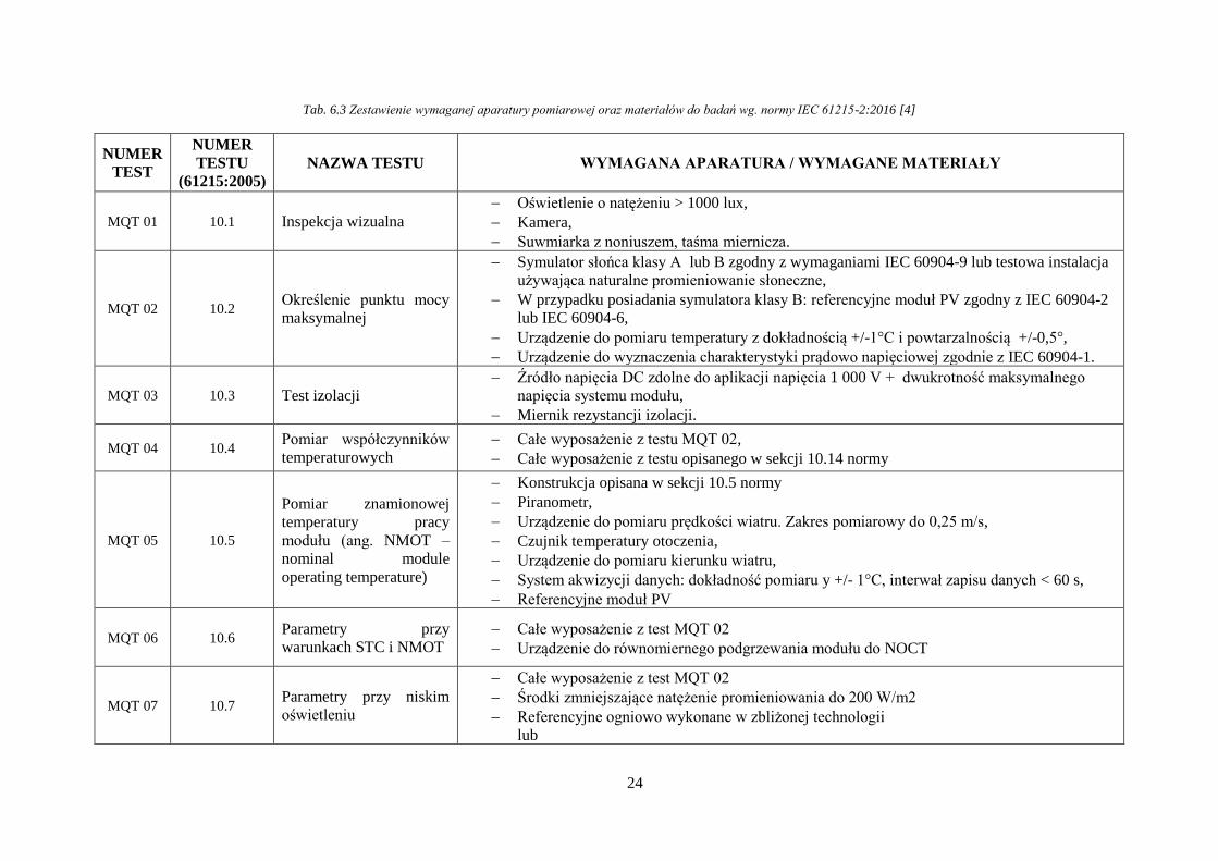
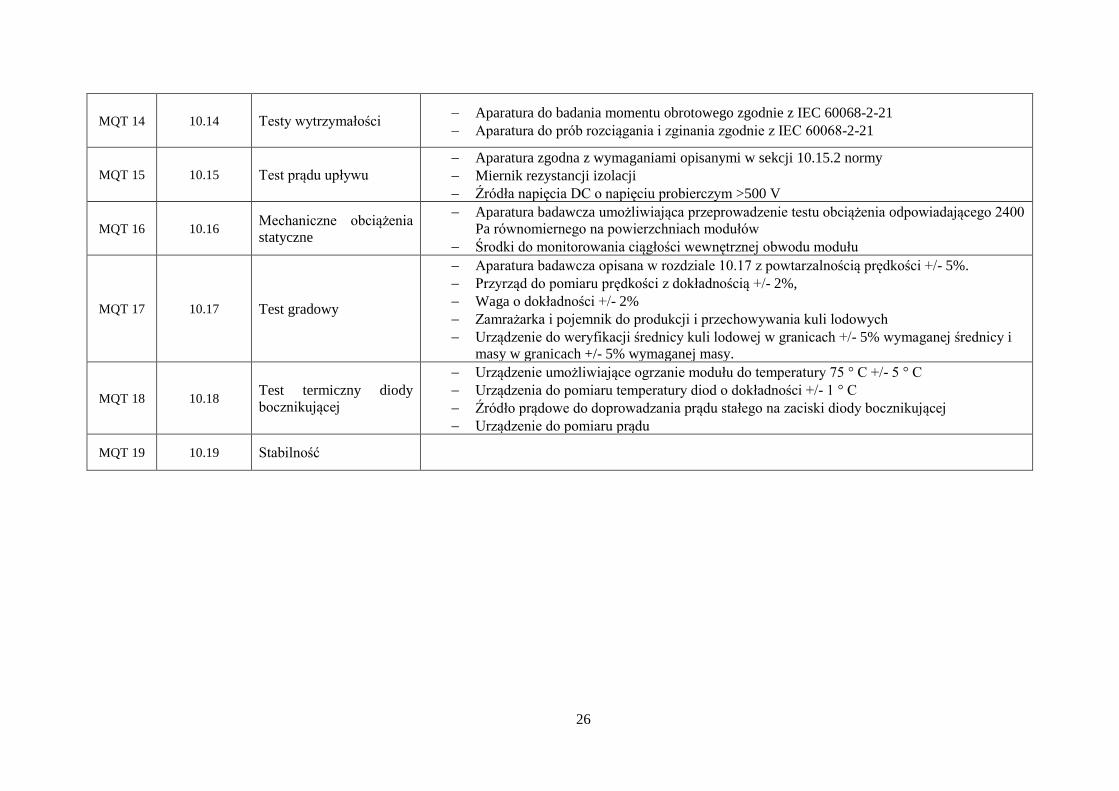
6.1.1 Wykaz aparatury
W Tab. 6.3 dokonano zestawienia aparatury wymaganej do przeprowadzenia testów zgodnie z
normą IEC 61215-2:2016.
Spośród całego zestawienia najważniejsze są trzy pozycje, które pozwalają przeprowadzić
większość z wymaganych testów:
Symulator słońca klasy A1,
Komora klimatyczna,
Miernik parametrów prądowo – napięciowych modułu.
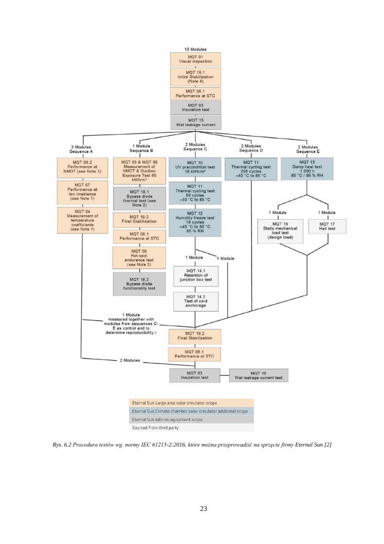
Poniżej przedstawiono graf z karty katalogowej firmy Eternal Sun przedstawiający koncepcje
przeprowadzenia testów zgodnych z normą IEC 61215-2:2016 z użyciem produktów firmy.
Kolorami:
pomarańczowym zaznaczono procesy które można wykonać test z użyciem
symulatora słońca produkcji Eternal Sun,
niebieskim kolejne testy dokupując u producenta komorę klimatyczną,
szarym – pozostałe urządzenia, które można zakupić u producenta
białym – pozostałe testy do których sprzęt należy pozyskać od innych producentów.
Karty katalogowe komory klimatycznej oraz symulatora słońca stanowią załącznik numer 1 i
2 do niniejszego opracowania.
1 Uwaga zgodnie z nomenklaturą symulator słońca klasy A spełnia wszystkie wymagania
dotyczące: 1) dopasowania spektralnego, 2) niejednorodność przestrzenna, 3) niejednorodność w
czasie na poziomie klasy A. W przypadku spełnienia choć jednego wymagania na poziomie B
symulator jest oznaczony klasą B
23
Rys. 6.2 Procedura testów wg. normy IEC 61215-2:2016, które można przeprowadzić na sprzęcie firmy Eternal Sun [2]
24
Tab. 6.3 Zestawienie wymaganej aparatury pomiarowej oraz materiałów do badań wg. normy IEC 61215-2:2016 [4]
NUMER
TEST
NUMER
TESTU
(61215:2005)
NAZWA TESTU WYMAGANA APARATURA / WYMAGANE MATERIAŁY
MQT 01 10.1 Inspekcja wizualna
Oświetlenie o natężeniu > 1000 lux,
Kamera,
Suwmiarka z noniuszem, taśma miernicza.
MQT 02 10.2 Określenie punktu mocy
maksymalnej
Symulator słońca klasy A lub B zgodny z wymaganiami IEC 60904-9 lub testowa instalacja
używająca naturalne promieniowanie słoneczne,
W przypadku posiadania symulatora klasy B: referencyjne moduł PV zgodny z IEC 60904-2
lub IEC 60904-6,
Urządzenie do pomiaru temperatury z dokładnością +/-1°C i powtarzalnością +/-0,5°,
Urządzenie do wyznaczenia charakterystyki prądowo napięciowej zgodnie z IEC 60904-1.
MQT 03 10.3 Test izolacji
Źródło napięcia DC zdolne do aplikacji napięcia 1 000 V + dwukrotność maksymalnego
napięcia systemu modułu,
Miernik rezystancji izolacji.
MQT 04 10.4 Pomiar współczynników
temperaturowych
Całe wyposażenie z testu MQT 02,
Całe wyposażenie z testu opisanego w sekcji 10.14 normy
MQT 05 10.5
Pomiar znamionowej
temperatury pracy
modułu (ang. NMOT –
nominal module
operating temperature)
Konstrukcja opisana w sekcji 10.5 normy
Piranometr,
Urządzenie do pomiaru prędkości wiatru. Zakres pomiarowy do 0,25 m/s,
Czujnik temperatury otoczenia,
Urządzenie do pomiaru kierunku wiatru,
System akwizycji danych: dokładność pomiaru y +/- 1°C, interwał zapisu danych < 60 s,
Referencyjne moduł PV
MQT 06 10.6 Parametry przy
warunkach STC i NMOT
Całe wyposażenie z test MQT 02
Urządzenie do równomiernego podgrzewania modułu do NOCT
MQT 07 10.7 Parametry przy niskim
oświetleniu
Całe wyposażenie z test MQT 02
Środki zmniejszające natężenie promieniowania do 200 W/m2
Referencyjne ogniowo wykonane w zbliżonej technologii
lub

25
Spektralne neutralne filtry promieniowania.
MQT 08 10.8 Ekspozycja na warunki
zewnętrzne
Miernik natężenia promieniowania słonecznego, dokładność +/- 5%
Konstrukcja do montażu modułu współpłaszczyznowego z miernikiem natężenia
napromienienia
Obciążenie rezystancyjne do utrzymywania modułu w pobliżu punktu maksymalnej mocy w
STC
Miernik natężenia promieniowania, dokładność +/- 5%
MQT 09 10.9
Test wytrzymałości na
gorące punkty (ang. hot-
spot)
Naturalne źródło promieniowania słonecznego lub ustalony symulator słońca (Irradiancja
>700 W/m², nierównomierność <+/- 2%, Stabilność temporalna <+/- 5%)
Naturalne źródło promieniowania słonecznego lub ustalony symulator słońca o klasie co
najmniej C (irradiancja 1000 W/m² 10%)
Aparatura do pomiaru charakterystyki prądowo – napięciowej modułu
Nieprzezroczyste przesłony: Testowanie zacienienia w 5% inkrementacji
Czujnik temperatury
MQT 10 10.10 Wstępne
kondycjonowanie UV
Miernik UV pracujący w zakresie długości fal 280-320 nm i 320-385 nm z dokładnością +/-
15%
Źródło światła UV o natężeniu promieniowania z nierównomiernością w płaszczyźnie
badania na poziomie +/- 15% i całkowitym natężeniu promieniowania UV <250 W / m²
Aparatura do pomiaru temperatury modułu w zakresie 60 5 ° C
Urządzenia do monitorowania temperatury z dokładnością +/- 2 ° C
MQT 11 10.11 Cykliczne testy
temperaturowe
Komora klimatyczna zdolna do wytwarzania cyklu temperaturowego zgodnie z rys. 11 z
dokładnością +/- 2 ° C przy niskich i wysokich wartościach ekstremalnych.
Aparatura do pomiaru i rejestracji temperatury modułu z dokładnością +/- 1 ° C.
Urządzenie do wzbudzenia przepływu prądu w module
Aparatura do pomiaru prądu przepływającego przez modułu
MQT 12 10.12 Testy mrożenia w
wysokiej wilgotności
Komory klimatyczne zdolne do wytworzenia cyklu temperatury / wilgotności z dokładnością
+/- 2 ° C i wilgotnością względną +/- 5% przy niskich i wysokich wartościach ekstremalnych.
Aparatura do pomiaru i rejestrowania temperatury modułu z dokładnością + / - 1 ° C.
Aparatura do pomiaru ciągłości obwodu wewnętrznego modułu
MQT 13 10.13 Test temperaturowy w
wysokiej wilgotności
Komora klimatyczna zdolna do przeprowadzenia testów zgodnie z IEC 60068-2-3 (85 2 °
C, 85 5% wilgotności względnej)
26
MQT 14 10.14 Testy wytrzymałości Aparatura do badania momentu obrotowego zgodnie z IEC 60068-2-21
Aparatura do prób rozciągania i zginania zgodnie z IEC 60068-2-21
MQT 15 10.15 Test prądu upływu
Aparatura zgodna z wymaganiami opisanymi w sekcji 10.15.2 normy
Miernik rezystancji izolacji
Źródła napięcia DC o napięciu probierczym >500 V
MQT 16 10.16 Mechaniczne obciążenia
statyczne
Aparatura badawcza umożliwiająca przeprowadzenie testu obciążenia odpowiadającego 2400
Pa równomiernego na powierzchniach modułów
Środki do monitorowania ciągłości wewnętrznej obwodu modułu
MQT 17 10.17 Test gradowy
Aparatura badawcza opisana w rozdziale 10.17 z powtarzalnością prędkości +/- 5%.
Przyrząd do pomiaru prędkości z dokładnością +/- 2%,
Waga o dokładności +/- 2%
Zamrażarka i pojemnik do produkcji i przechowywania kuli lodowych
Urządzenie do weryfikacji średnicy kuli lodowej w granicach +/- 5% wymaganej średnicy i
masy w granicach +/- 5% wymaganej masy.
MQT 18 10.18 Test termiczny diody
bocznikującej
Urządzenie umożliwiające ogrzanie modułu do temperatury 75 ° C +/- 5 ° C
Urządzenia do pomiaru temperatury diod o dokładności +/- 1 ° C
Źródło prądowe do doprowadzania prądu stałego na zaciski diody bocznikującej
Urządzenie do pomiaru prądu
MQT 19 10.19 Stabilność

27
Na Rys. 6.3 przedstawiono procedurę oraz kolejność wykonywania testów według normy IEC
61215-1:2016.
Rys. 6.3 Procedura testów konstrukcji i aprobaty typu dla modułów fotowoltaicznych wg. IEC 61215-1:2016
28
6.2 Standardy certyfikacji bezpieczeństwa modułów PV (IEC 61730)
W normie IEC 61730-2:2007 określono wymagania dotyczące badań modułów
fotowoltaicznych (PV), które mają zapewnić ich bezpieczne działanie w okresie spodziewanego
okresu eksploatacji.
Badania podzielono na następujące grupy:
Wstępne kondycjonowanie,
Testy ogólne,
Testy bezpieczeństwa elektrycznego,
Testy bezpieczeństwa pożarowego,
Testy obciążeń mechanicznych,
Testy komponentów.
Sekwencja testów ma na celu zweryfikowanie bezpieczeństwa użytkowania modułów PV,
których konstrukcja została oparta na wytycznych zawartych w normie IEC 61730-1. Zdefiniowano
podstawowe wymagania prób bezpieczeństwa użytkowania oraz prób dodatkowych wynikających z
ostatecznego zastosowana modułu.
Testy bezpieczeństwa według normy IEC 61730-2 są oznaczane dwucyfrowym kodem
poprzedzonym akronimem MST (ang. module safety test).
W zależności od zastosowania modułu fotowoltaicznego norma definiuje trzy klasy modułów:
1) Klasa A (dostęp ogólny, niebezpieczne napięcia, niebezpieczne moce) – moduły w tej klasie
mogą być użyte w systemach pracujących przy napięciach większych niż 50V lub mocach
większych niż 240W gdzie dostęp do kontaktów jest przewidziany. Moduły uznane za
bezpieczne według norm IEC 61730-1 oraz IEC 61730-2 są uznawane za spełniające
wymagania bezpieczeństwa urządzeń elektrycznych klasy II (wg. IEC 61140).
2) Klasa B (dostęp ograniczony, niebezpieczne napięcia, niebezpieczne moce) – moduły w tej
klasie mogą być użyte w systemach o ograniczonym dostępie publicznym (np. przez
ogrodzenia, lokalizację na dachach itp.) Moduły w tej klasie zapewniają bezpieczeństwo przez
podstawową izolację i są uznane za urządzenia elektryczne klasy 0 (wg. IEC 61140).
3) Klasa C (ograniczone napięcie i moc) – moduły w tej klasie pracują w systemach o napięciach
poniżej 50V i mocach poniżej 240W, dostęp do kontaktów jest przewidziany. Moduły uznane
za bezpieczne według norm IEC 61730-1 oraz IEC 61730-2 są uznawane za spełniające
wymagania bezpieczeństwa urządzeń elektrycznych klasy III (wg. IEC 61140).
W zależności od klasyfikacji modułu, niektóre testy bezpieczeństwa mogą zostać pominięte,
gdyż nie są wymagane. W poniżej tabeli przedstawiono klasyfikację modułów fotowoltaicznych wg.
normy IEC 61730-2:2007.

29
Tab. 6.4 Klasyfikacja modułów fotowoltaicznych wg. IEC 61730-2:2007 [10]
KLASA
A
KLASA
B
KLASA
C
TEST
X X X MST 51 Cykliczne testy temperaturowe
X X X MST 52 Test mrożenia w wysokiej wilgotności
X X X MST 53 Test temperaturowy w wysokiej wilgotności
X X X MST 54 Wstępne kondycjonowanie UV
X X X MST 01 Inspekcja wizualna
X X MST 11 Test dostępności
X X MST 12 Wrażliwość na cięcie (nie dotyczy szklanych powierzchni)
X X X MST 13 Test ciągłości uziemienia (dotyczy tylko jeśli rama jest
metalowa)
X X2 MST 14 Test impulsów napięciowych
X X2 MST 16 Test izolacji
X X MST 17 Test prądu upływu
X X X MST 42 Testy wytrzymałości przyłączy
X X X 4) MST 21 Test temperaturowy
X X X MST 22 Test wytrzymałości na gorące punkty (ang. hot-spot)
X3 MST 23 Test ogniowy
X X MST 26 Test przeciążenia prądem wstecznym
X X MST 32 Test łamania modułu
X X X MST 34 Mechaniczne obciążenia statyczne
X MST 15 Test częściowego wyładowania
X X MST 33 Zginanie przewodów
X X X MST 44 Test zrywania puszki przyłączeniowej
2 Różne definicje testu dla klas A i B
3 Klasa odporności ogniowej C jest wymagana jest dla instalacji na dachach

30
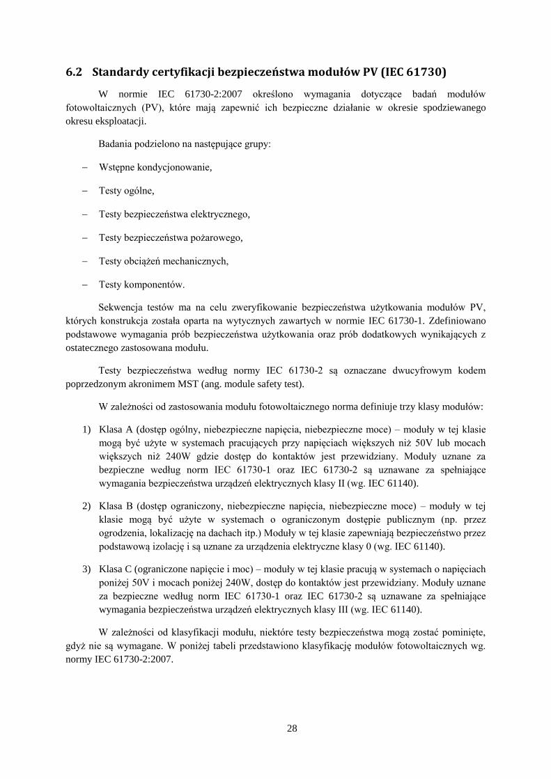
Tab. 6.5 Testy bezpieczeństwa modułów fotowoltaicznych wg. normy IEC 61730-2:2007. [10].
NUMER
TEST NAZWA TESTU WARUNKI TESTU
WSTĘPNE KONDYCJONOWANIE
MST 51 Cykliczne testy
temperaturowe Zgodnie z IEC 61215 - MQT 11 (Tab. 6.2)
MST 52 Test mrożenia w wysokiej
wilgotności Zgodnie z IEC 61215 - MQT 12 (Tab. 6.2)
MST 53 Test temperaturowy w
wysokiej wilgotności Zgodnie z IEC 61215 - MQT 13 (Tab. 6.2)
MST 54 Wstępne
kondycjonowanie UV Zgodnie z IEC 61215 - MQT 10 (Tab. 6.2)
TESTY OGÓLNE
MST 01 Inspekcja wizualna Zgodnie z IEC 61215 - MQT 01 (Tab. 6.2)
TESTY BEZPIECZEŃSTWA ELEKTRYCZNEGO
MST 11 Test dostępności Zgodnie z ANSI/UL 1703
MST 12
Wrażliwość na cięcie (nie
dotyczy szklanych
powierzchni)
Zgodnie z ANSI/UL 1703
MST 13
Test ciągłości uziemienia
(dotyczy tylko jeśli rama
jest metalowa)
Zgodnie z ANSI/UL 1703
MST 14 Test napięcia udarowego Zgodnie z IEC 60664-1. W zależności od napięcia pracy modułu i kategorii odporności na przepięcia moduły mogą
być testowane wyładowaniami od 330V do 4kV.

31
MST 16 Test izolacji Zgodnie z IEC 61215 - MQT 03 (Tab. 6.2)
MST 17 Test prądu upływu Zgodnie z IEC 61215 - MQT 15 (Tab. 6.2)
MST 42 Testy wytrzymałości
przyłączy Zgodnie z IEC 61215 - MQT 14 (Tab. 6.2)
TESTY BEZPIECZEŃSTWA POŻAROWEGO
MST 21 Test temperaturowy Zgodnie z ANSI/UL 1703
MST 22
Test wytrzymałości na
gorące punkty (ang. hot-
spot)
Zgodnie z IEC 61215 - MQT 09 (Tab. 6.2)
MST 23 Test ogniowy Zgodnie z ANSI/UL 790
MST 25 Test termiczny diody
bocznikującej Zgodnie z IEC 61215 - MQT 18 (Tab. 6.2)
MST 26 Test przeciążenia prądem
wstecznym Zgodnie z ANSI/UL 1703
TESTY OBCIĄŻEŃ MECHANICZNYCH
MST 32 Test łamania modułu ANSI Z97.1
MST 34 Mechaniczne obciążenia
statyczne Zgodnie z IEC 61215 - MQT 16 (Tab. 6.2)
TESTY OBCIĄŻEŃ MECHANICZNYCH
32
MST 15 Test wyładowań
niezupełnych
Sposób wykonywania testów opisano w IEC 60664-1. Test uwzględnia przykładanie ładunku (z naładowanego
kondensatora) do przewodzących i nieprzewodzących elementów modułu.
MST 33 Zginanie przewodów Zgodnie z ANSI/UL 514C
MST 44
Test otworów pod dławiki
w skrzynce
przyłączeniowej
Zgodnie z ANSI/UL 514C
33
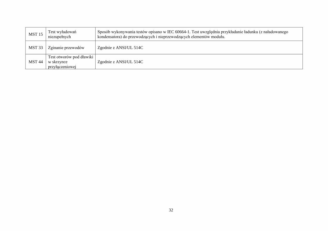
Rys. 6.4 Procedura testów bezpieczeństwa i aprobaty typu dla modułów fotowoltaicznych wg. IEC 61730-2:2007 cz.1

34
Rys. 6.5 Procedura testów bezpieczeństwa i aprobaty typu dla modułów fotowoltaicznych wg. IEC 61730-2:2007 cz.2
35
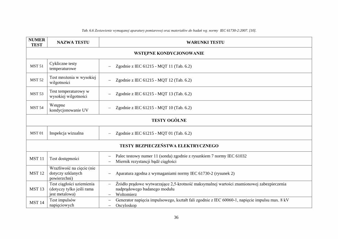
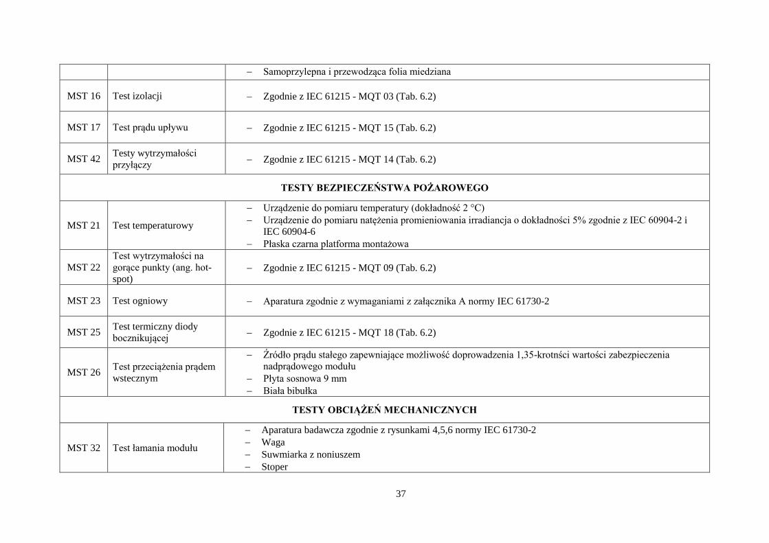
6.2.1 Wykaz aparatury
W Tab. 6.6 przedstawiono zestawienia aparatury wymaganej do przeprowadzenia testów
zgodnie z normą IEC 61730-2:2007.
Większość aparatury wymaganej do przeprowadzenia testów jest powtórzeniem aparatury
wymaganej zgodnie z normą IEC 61215-2:2016. Inne urządzenia są dedykowaną konstrukcją, której
wykonanie zostało przedstawione w normie .
36
Tab. 6.6 Zestawienie wymaganej aparatury pomiarowej oraz materiałów do badań wg. normy IEC 61730-2:2007. [10].
NUMER
TEST NAZWA TESTU WARUNKI TESTU
WSTĘPNE KONDYCJONOWANIE
MST 51 Cykliczne testy
temperaturowe Zgodnie z IEC 61215 - MQT 11 (Tab. 6.2)
MST 52 Test mrożenia w wysokiej
wilgotności Zgodnie z IEC 61215 - MQT 12 (Tab. 6.2)
MST 53 Test temperaturowy w
wysokiej wilgotności Zgodnie z IEC 61215 - MQT 13 (Tab. 6.2)
MST 54 Wstępne
kondycjonowanie UV Zgodnie z IEC 61215 - MQT 10 (Tab. 6.2)
TESTY OGÓLNE
MST 01 Inspekcja wizualna Zgodnie z IEC 61215 - MQT 01 (Tab. 6.2)
TESTY BEZPIECZEŃSTWA ELEKTRYCZNEGO
MST 11 Test dostępności Palec testowy numer 11 (sonda) zgodnie z rysunkiem 7 normy IEC 61032
Miernik rezystancji bądź ciągłości
MST 12
Wrażliwość na cięcie (nie
dotyczy szklanych
powierzchni) Aparatura zgodna z wymaganiami normy IEC 61730-2 (rysunek 2)
MST 13
Test ciągłości uziemienia
(dotyczy tylko jeśli rama
jest metalowa)
Źródło prądowe wytwarzające 2,5-krotność maksymalnej wartości znamionowej zabezpieczenia
nadprądowego badanego modułu
Woltomierz
MST 14 Test impulsów
napięciowych
Generator napięcia impulsowego, kształt fali zgodnie z IEC 60060-1, napięcie impulsu max. 8 kV
Oscyloskop
37
Samoprzylepna i przewodząca folia miedziana
MST 16 Test izolacji Zgodnie z IEC 61215 - MQT 03 (Tab. 6.2)
MST 17 Test prądu upływu Zgodnie z IEC 61215 - MQT 15 (Tab. 6.2)
MST 42 Testy wytrzymałości
przyłączy Zgodnie z IEC 61215 - MQT 14 (Tab. 6.2)
TESTY BEZPIECZEŃSTWA POŻAROWEGO
MST 21 Test temperaturowy
Urządzenie do pomiaru temperatury (dokładność 2 °C)
Urządzenie do pomiaru natężenia promieniowania irradiancja o dokładności 5% zgodnie z IEC 60904-2 i
IEC 60904-6
Płaska czarna platforma montażowa
MST 22
Test wytrzymałości na
gorące punkty (ang. hot-
spot) Zgodnie z IEC 61215 - MQT 09 (Tab. 6.2)
MST 23 Test ogniowy Aparatura zgodnie z wymaganiami z załącznika A normy IEC 61730-2
MST 25 Test termiczny diody
bocznikującej Zgodnie z IEC 61215 - MQT 18 (Tab. 6.2)
MST 26 Test przeciążenia prądem
wstecznym
Źródło prądu stałego zapewniające możliwość doprowadzenia 1,35-krotnści wartości zabezpieczenia
nadprądowego modułu
Płyta sosnowa 9 mm
Biała bibułka
TESTY OBCIĄŻEŃ MECHANICZNYCH
MST 32 Test łamania modułu
Aparatura badawcza zgodnie z rysunkami 4,5,6 normy IEC 61730-2
Waga
Suwmiarka z noniuszem
Stoper

38
MST 34 Mechaniczne obciążenia
statyczne Zgodnie z IEC 61215 - MQT 16 (Tab. 6.2)
TESTY OBCIĄŻEŃ MECHANICZNYCH
MST 15 Test częściowego
wyładowania Urządzenie do pomiaru ładunku lub miernik zakłóceń radiowych zgodnie z IEC 60664-1
MST 33 Zginanie przewodów Zestaw testowy zgodnie z rys. 7 normy IEC 61730-2
Obciążenia: 220, 330, 490 N
MST 44
Test otworów pod dławiki
w skrzynce
przyłączeniowej
Trzpień z płaskim końcem (długość> 38 mm, średnica 6,4 mm)
Dynamometr
Lodówka: -20 ° C ± 1 ° C
Suwmiarka z noniuszem

39
6.3 Standardy certyfikacji modułów w korozyjnym środowisku mgły solnej (IEC 61701)
Norma IEC 61701 norma opisuje sekwencje testowe przydatne do określenia odporności
innych modułów PV do korozji z mgły solnej zawierającej Cl-(NaCl, MgCl2, itd.).
Wilgotna wysoko korozyjna atmosfera, taka jak środowisko morskie, mogą ulec degradacji
niektóre elementy, moduły fotowoltaiczne, korozja metalowych części, pogorszenie właściwości
niektórych materiałów niemetalicznych - takich jak powłok ochronnych i tworzyw sztucznych - przez
asymilację soli itp.) powodując trwałe uszkodzenia, które mogą zaszkodzić ich funkcjonowaniu.
Wszystkie badania zawarte w sekwencji, z wyjątkiem diody bypass testu sprawności, są w
pełni opisane w IEC 61215, IEC 61646, IEC 62108, IEC 61730-2 i IEC 60068-2-52. Są one połączone
w niniejszym standardzie zapewnienie środków dla oceny ewentualnych uszkodzeń spowodowanych
w użytych modułach fotowoltaicznych podczas pracy w środowisku wilgotnym z wysokimi stężenia
rozpuszczonej soli (NaCl).
W zależności od specyficznych charakteru otaczającej atmosfery, do której moduł jest
narażony w czasie rzeczywistej pracy kilka ważkość badania mogą być stosowane, zgodnie z IEC
60068-2-52. Na przykład surowości ma być używany do modułów fotowoltaicznych stosowanych w
środowisku morskim lub w bliskim sąsiedztwie do morza. Ważkość do są przeznaczone dla modułów
fotowoltaicznych działających w miejscach, gdzie nie może być zmiana między atmosferą sól
ładunkiem i suche, na przykładach, w miejscach gdzie sól jest używana do stopienia formacje lodowe.
1) Testy wstępne (weryfikacja paramentów elektrycznych) – 3 moduły
a. Dla ogniw krystalicznych:
i. Określenie mocy maksymalnej modułu (MQT 02 wg. IEC 61215),
ii. Test prądu upływu (MQT 15 wg. IEC 61215),
iii. Inspekcja wizualna (MST 01 wg. IEC 61730-2),
iv. Test ciągłości uziemienia (MST 13 wg. IEC 61730-2),
v. Test izolacji (MST 16 wg. IEC 61730-2),
vi. Test diody bocznikującej (wg. 61701).
b. Dla ogniw cienkowarstwowych:
i. Parametry przy warunkach STC (10.6 wg. IEC 61646),
ii. Test prądu upływu (10.6 wg. IEC 61646),
iii. Test nasycania światłem (ang. light soaking) (10.6 wg. IEC 61646),
iv. Inspekcja wizualna (MST 01 wg. IEC 61730-2),
v. Test ciągłości uziemienia (MST 13 wg. IEC 61730-2),
vi. Test izolacji (MST 16 wg. IEC 61730-2),

40
vii. Test diody bocznikującej (wg. 61701).
c. Dla ogniw z koncentratorem światła:
i. Inspekcja wizualna (10.1 wg. IEC 62108),
ii. Test parametrów elektrycznych (10.2 wg. IEC 62108,
iii. Test ciągłości uziemienia (10.3 wg. IEC 62108),
iv. Test izolacji (10.4 wg. IEC 62108),
v. Test prądu upływu (10.5 wg. IEC 62108),
vi. Test diody bocznikującej (wg. 61701).
2) Test mgły solnej – 2 moduły, jeden pozostawiony do kontroli:
d. Test wykonywany jest w komorze wytwarzająca mgłę solną (rozpylającą
przygotowany roztwór NaCl) zgodnie z normą IEC 60068-2-52. Norma przewiduje
stopień kilka stopni dotkliwości testu, z których każda może zostać użyta z wyjątkiem
poziomu 2,
e. Mycie modułów po teście,
f. Mycie wykonywane jest strumieniem wody kranowej (bez podwyższania ciśnienia)
przez maksymalnie 5 minut na każdy metr kwadratowy modułu. Następnie moduł jest
opłukiwany wodą destylowaną lub demineralizowaną. Temperatura wody nie może
przekraczać 35⁰C. Nadmiar wody na module może być strząśnięty lub suszony
powietrzem z użyciem wentylatora. Nie dozwolone jest używanie ścierek tekstylnych
lub papierowych ani jakiekolwiek pocieranie powierzchni modułu, aby nie wywołać
ścierania potencjalnie wytworzonych warstw korozyjnych. Po wysuszeniu należy
niezwłocznie przejść do kolejnych testów.
3) Testy końcowe (analogicznie do testów wstępnych
g. Dla ogniw krystalicznych:
i. Określenie mocy maksymalnej modułu (MQT 02 wg. IEC 61215),
ii. Test prądu upływu (MQT 15 wg. IEC 61215),
iii. Inspekcja wizualna (MST 01 wg. IEC 61730-2),
iv. Test ciągłości uziemienia (MST 13 wg. IEC 61730-2),
v. Test izolacji (MST 16 wg. IEC 61730-2),
vi. Test diody bocznikującej (wg. 61701).
h. Dla ogniw cienkowarstwowych:
i. Parametry przy warunkach STC (10.6 wg. IEC 61646),
ii. Test prądu upływu (10.6 wg. IEC 61646),

41
iii. Test nasycania światłem (ang. light soaking) (10.6 wg. IEC 61646) ,
iv. Inspekcja wizualna (MST 01 wg. IEC 61730-2),
v. Test ciągłości uziemienia (MST 13 wg. IEC 61730-2),
vi. Test izolacji (MST 16 wg. IEC 61730-2),
vii. Test diody bocznikującej (wg. 61701).
i. Dla ogniw z koncentratorem światła:
i. Inspekcja wizualna (10.1 wg. IEC 62108),
ii. Test parametrów elektrycznych (10.2 wg. IEC 62108),
iii. Test ciągłości uziemienia (10.3 wg. IEC 62108),
iv. Test izolacji (10.4 wg. IEC 62108),
v. Test prądu upływu (10.5 wg. IEC 62108),
vi. Test diody bocznikującej (wg. 61701).
4) Wymagania dla pozytywnego przejścia testu:
j. Wynik testu uznaje się za pozytywny, jeśli
i. Kryteria wszystkich testów końcowych zostaną spełnione.
ii. Wartość mocy maksymalnej:
1. Dla modułów krystalicznych – nie może spaść o 5% od wartości
mocy znamionowej,
2. Dla modułów cienkowarstwowych – po nasyceniu światłem nie
spadnie poniżej 90% wartości mocy minimalnej w specyfikacji
producenta,
3. Dla modułów z koncentratorem światła – nie może spaść o 5% od
wartości mocy znamionowej (przy teście na symulatorze słońca) lub
7% przy teście na naturalnym słońcu.
iii. Moduły nie wykazują jawnych uszkodzeń (na podstawie inspekcji wizualnej
MST 01 wg. 61730-2) oraz korozji i defektów mogących wpływać na
właściwości modułu podczas cyklu użytkowania.

42
7 Bibliografia
[1] IEC 61215-1:2016-01 Terrestrial photovoltaic (PV) modules - Design qualification and type
approval - Part 1: Test requirements
[2] IEC 61215-1-1:2016-10 Terrestrial photovoltaic (PV) modules - Design qualification and
type approval - Part 1-1: Special requirements for testing of crystalline silicon photovoltaic
(PV) modules
[3] IEC 61215-1-2:2016-07 Terrestrial photovoltaic (PV) modules - Design qualification and
type approval - Part 1-2: Special requirements for testing of thin-film Cadmium Telluride
(CdTe) based photovoltaic (PV) modules
[4] IEC 61215-2:2016-05 Terrestrial photovoltaic (PV) modules - Design qualification and type
approval - Part 2: Test procedures
[5] IEC 61730-1:2007 Photovoltaic (PV) module safety qualification - Part 1: Requirements for
construction
[6] IEC 61730-1:2007/A1:2012 Photovoltaic (PV) module safety qualification - Part 1:
Requirements for construction
[7] IEC 61730-1:2007/A2:2013-11 Photovoltaic (PV) module safety qualification - Part 1:
Requirements for construction
[8] IEC 61730-1:2007/A11:2015-06 Photovoltaic (PV) module safety qualification - Part 1:
Requirements for construction
[9] IEC 61730-2:2007 Photovoltaic (PV) module safety qualification - Part 2: Requirements for
testing
[10] IEC 61730-2:2007/A1:2012 Photovoltaic (PV) module safety qualification - Part 2:
Requirements for testing
[11] IEC 62108:2017-02 Concentrator photovoltaic (CPV) modules and assemblies - Design
qualification and type approval
[12] IEC 61701:2012 Salt mist corrosion testing of photovoltaic (PV) modules
[13] UL 1703 Standard for Flat-Plate Photovoltaic Modules and Panels
[14] UL 790 Standard for Standard Test Methods for Fire Tests of Roof Coverings
[15] IEC 60891:2010 Photovoltaic devices - Procedures for temperature and irradiance corrections
to measured I-V characteristics
[16] IEC 60664-1:2011 Insulation coordination for equipment within low-voltage systems - Part 1:
Principles, requirements and tests
[17] IEC 60904-1:2007 Photovoltaic devices - Part 1-1: Measurement of current-voltage
characteristics
[18] IEC 60904-3:2016-11 Photovoltaic devices - Part 3: Measurement principles for terrestrial
photovoltaic (PV) solar devices with reference spectral irradiance data
[19] IEC 60904-10:2009 Photovoltaic devices - Part 10: Methods of linearity measurement
[20] UL 514C Standard for Nonmetallic Outlet Boxes, Flush-Device Boxes, and Covers
[21] ANSI Z97.1 Safety Glazing Materials Used in Buildings - Safety Performance Specifications
and Methods of Test
[22] PN-EN ISO/IEC 17025:2005 General requirements for the competence of testing and
calibration laboratories

43
[23] Karta katalogowa Climate chamber solar simulator, Ethernal Sun
[24] Strona internetowa: https://www.iecee.org
[25] Strona internetowa: http://www.elektroonline.pl/news/8126,Nowoczesne-metody-badan-
modulow-fotowoltaicznych-na-targach-greenPower-w-Poznaniu
[26] Strona internetowa: https://www.pi-berlin.com/prasowy_greenpower_2015.html
[27] IECEE PV PROGRAM. PROCEDURE FOR CERTIFICATION OF PHOTOVOLTAIC (PV)
PRODUCTS AND THE USE OF THE IECEE PV QUALITY MARK AND PV QUALITY.
SEAL. OD-2051-Ed.1.0. 2010-09-17

44
8 Spis rysunków
Rys. 5.1 Role partnerów w systemie certyfikacji IECEE [24] ................................................................ 7
Rys. 5.2 PV Quality Mark [27] ............................................................................................................. 10
Rys. 5.3 PV Quality Seal [27] ............................................................................................................... 10
Rys. 5.4 Przebieg procesu certyfikacji w ramach programu PV GAP [27] .......................................... 11
Rys. 5.5 Akredytowane laboratorium certyfikacji modułów fotowoltaicznych Photovoltaik Institut
Berlin. Źródło: https://www.pi-berlin.com/prasowy_greenpower_2015.html ..................................... 12
Rys. 5.6 Armatka z gradem o średnicy maks. 75mm do badania odporności na gradobicie. Źródło:
https://www.pi-berlin.com/prasowy_greenpower_2015.html ............................................................... 13
Rys. 5.7 Symulator światła słonecznego wykorzysywany do wykonywania testów wydajności
modułów. Źródło: https://www.pi-berlin.com/prasowy_greenpower_2015.html ................................ 13
Rys. 5.8 Akredytowane laboratorium certyfikacji modułów fotowoltaicznych Photovoltaik Institut
Berlin. Źródło: https://www.pi-berlin.com/prasowy_greenpower_2015.html ..................................... 14
Rys. 5.9 Komora klimatyczna do badania jakości modułu. Źródło: https://www.pi-
berlin.com/prasowy_greenpower_2015.html ........................................................................................ 14
Rys. 6.1 Podział norm dotyczących certyfikacji modułów fotowoltaicznych ....................................... 17
Rys. 6.2 Procedura testów wg. normy IEC 61215-2:2016, które można przeprowadzić na sprzęcie
firmy Eternal Sun [2] ............................................................................................................................. 23
Rys. 6.3 Procedura testów konstrukcji i aprobaty typu dla modułów fotowoltaicznych wg. IEC 61215-
1:2016 .................................................................................................................................................... 27
Rys. 6.4 Procedura testów bezpieczeństwa i aprobaty typu dla modułów fotowoltaicznych wg. IEC
61730-2:2007 cz.1 ................................................................................................................................. 33
Rys. 6.5 Procedura testów bezpieczeństwa i aprobaty typu dla modułów fotowoltaicznych wg. IEC
61730-2:2007 cz.2 ................................................................................................................................. 34

45
9 Spis tabel
Tab. 5.1 Ilość laboratoriów CBTL przeprowadzających badania zgodnie z kolejnymi wersjami normy
61215 ....................................................................................................................................................... 8
Tab. 5.2 Ilość laboratoriów CBTL przeprowadzających badania zgodnie z kolejnymi wersjami normy
61215 ....................................................................................................................................................... 9
Tab. 5.3 Ilość laboratoriów CBTL przeprowadzających badania zgodnie z kolejnymi wersjami normy
62108 ....................................................................................................................................................... 9
Tab. 5.4 Ilość laboratoriów CBTL przeprowadzających badania zgodnie z kolejnymi wersjami normy
61701 ....................................................................................................................................................... 9
Tab. 6.1 Wykaz norm obowiązujących w Polsce i na terenie Unii Europejskiej dotyczący certyfikacji
modułów fotowoltaicznych ................................................................................................................... 15
Tab. 6.2 Standardy testowania modułów fotowoltaicznych wg. normy IEC 61215-2:2016 [4] ...............
............................................................................................................................................................... 19
Tab. 6.3 Zestawienie wymaganej aparatury pomiarowej oraz materiałów do badań wg. normy IEC
61215-2:2016 [4] ................................................................................................................................... 24
Tab. 6.4 Klasyfikacja modułów fotowoltaicznych wg. IEC 61730-2:2007 [10] ................................... 29
Tab. 6.5 Testy bezpieczeństwa modułów fotowoltaicznych wg. normy IEC 61730-2:2007. [10]. ..... 30
Tab. 6.6 Zestawienie wymaganej aparatury pomiarowej oraz materiałów do badań wg. normy IEC
61730-2:2007. [10]. ............................................................................................................................... 36
46
10 Załączniki
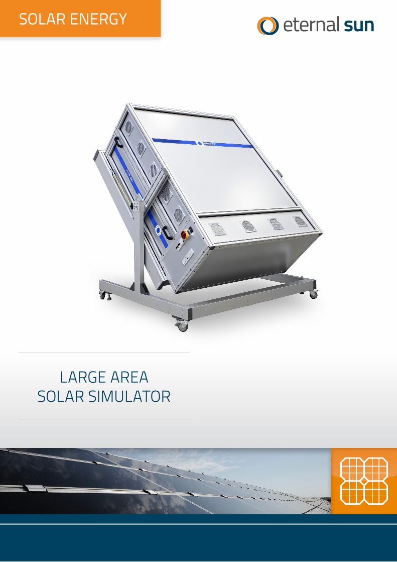
[1] Karta katalogowa: Large area solar simulator, Ethernal Sun
[2] Karta katalogowa: Climate chamber solar simulator, Ethernal Sun
[3] IECEE PV Certification – broszura
[4] IECEE PV GAP – szczegółowy opis programu
LARGE AREA SOLAR SIMULATOR
SOLAR ENERGY
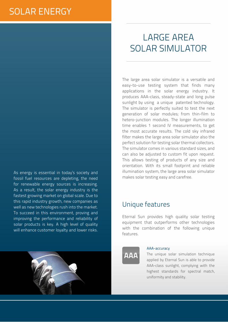
As energy is essential in today’s society and fossil fuel resources are depleting, the need for renewable energy sources is increasing. As a result, the solar energy industry is the fastest growing market on global scale. Due to this rapid industry growth, new companies as well as new technologies rush into the market. To succeed in this environment, proving and improving the performance and reliability of solar products is key. A high level of quality will enhance customer loyalty and lower risks.
SOLAR ENERGY
Eternal Sun provides high quality solar testing equipment that outperforms other technologies with the combination of the following unique features.
Unique features
AAA-accuracyThe unique solar simulation technique applied by Eternal Sun is able to provide AAA-class sunlight, complying with the highest standards for spectral match, uniformity and stability.
LARGE AREA SOLAR SIMULATOR
The large area solar simulator is a versatile and easy-to-use testing system that finds many applications in the solar energy industry. It produces AAA-class, steady-state and long pulse sunlight by using a unique patented technology. The simulator is perfectly suited to test the next generation of solar modules; from thin-film to hetero-junction modules. The longer illumination time enables 1 second IV measurements, to get the most accurate results. The cold sky infrared filter makes the large area solar simulator also the perfect solution for testing solar thermal collectors. The simulator comes in various standard sizes, and can also be adjusted to custom fit upon request. This allows testing of products of any size and orientation. With its small footprint and reliable illumination system, the large area solar simulator makes solar testing easy and carefree.

In the solar energy industry, improving the performance while maintaining the reliability of products and systems is key. This requires a dedicated test setup. Our large area solar simulator gives you accurate in-depth knowledge about the behavior of solar products and systems.
Applications
Any sizeThe modular product design allows us to be flexible and provide customers with equipment that suits their needs; we provide solar simulation up to any size.
Steady stateOur equipment produces continuous and long pulse artificial sunlight, creating clearly defined standard conditions to make sure that results are reproducible.
CertificationOur continuous solar simulation allows certification institutes to execute a wide range of test procedures, ensuring that tested modules comply with the international standards.
Performance testingThe large area solar simulator allows you to carry out I-V curve measurements to determine the basic parameters of your PV modules: power output, efficiency, open circuit voltage, short circuit current, resistances, etc. The setup also enables light soaking, pre-conditioning and hot-spot endurance tests. Both PV modules and solar thermal collectors can be tested, depending on the chosen add-on equipment.
Main benefitsThe large area solar simulator incorporates special benefits for institutes and companies working in the solar energy industry.
Testing of all new PV technologieswith steady-state and long pulse illumination for modules that have a longer response time to light pulses.
Wide scope of test procedurescompared to traditional flash testing, because of continuous illumination.
Highest measurement accuracyAAA-class spectrum, uniformity and stability in compliance with IEC 60904 standard.
Turnkey, small footprint and low maintenancerunning for 1800 hours non-stop.
Eternal Sun B.V. | +31 15 744 0161 | [email protected] 12-14 | 2629 JD Delft | The Netherlands
Copyright © 2012 Eternal Sun B.V. All rights reserved
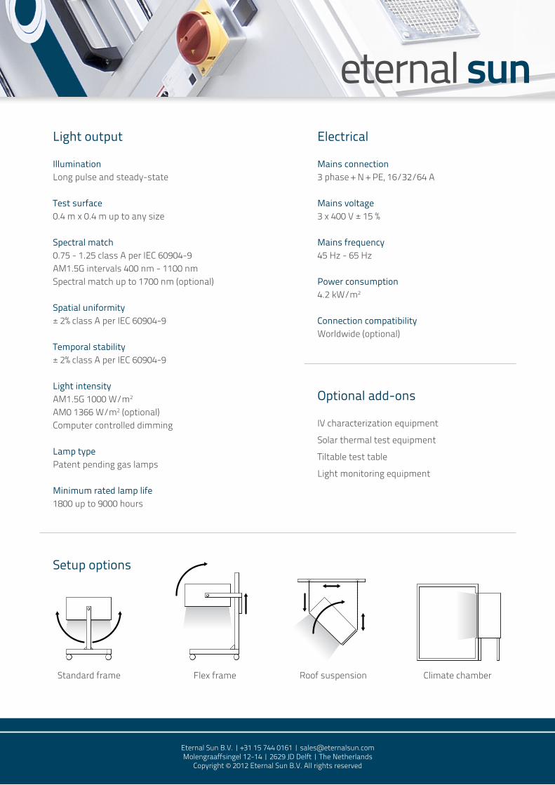
Light output
IlluminationLong pulse and steady-state
Test surface0.4 m x 0.4 m up to any size
Spectral match0.75 - 1.25 class A per IEC 60904-9 AM1.5G intervals 400 nm - 1100 nmSpectral match up to 1700 nm (optional)
Spatial uniformity± 2% class A per IEC 60904-9
Temporal stability± 2% class A per IEC 60904-9
Light intensityAM1.5G 1000 W/m2
AM0 1366 W/m2 (optional)Computer controlled dimming
Lamp typePatent pending gas lamps
Minimum rated lamp life1800 up to 9000 hours
Electrical
Mains connection3 phase + N + PE, 16/32/64 A
Mains voltage3 x 400 V ± 15 %
Mains frequency45 Hz - 65 Hz
Power consumption4.2 kW/m2
Connection compatibility Worldwide (optional)
Optional add-ons
IV characterization equipment
Solar thermal test equipment
Tiltable test table
Light monitoring equipment
Setup options
Standard frame Flex frame Roof suspension Climate chamber

CLIMATE CHAMBER SOLAR SIMULATOR
SOLAR ENERGY

SOLAR ENERGY
Eternal Sun provides high quality solar testing equipment that outperforms other technologies with the combination of the following unique features.
In the solar energy industry, improving the performance and reliability of products and systems is key. This requires a dedicated test setup. Our climate chamber solar simulator can be used for
Applications
Unique features
AAA-accuracyThe unique solar simulation technique applied by Eternal Sun is able to provideAAA-class sunlight inside the climate chamber, complying with the highest IEC 60904-9 standards for spectral match, uniformity and stability.
Any sizeThe modular product design allows us to be flexible and provide customers with equipment that suits their needs; we provide solutions for both cell and module research, starting from 50 cm x 50 cm test surfaces up to 1.6 m x 1.1 m.
Steady stateOur equipment produces continuous artificial sunlight that stays constant over long periods of time, creating clearly defined standard conditions to make sure that results are reproducible. A shutter provides pulsed illumination for low temperature tests.
CLIMATE CHAMBER SOLAR SIMULATOR
New PV technologies claim to be more efficient, cost less and have longer life cycles. To prove that your PV technology is most reliable, you need a dedicated setup. Our class AAA climate chamber solar simulators allow you to get unprecedented performance and reliability data to gain new research insights. It is perfectly suited for testing current and next generation solar cells and modules such as high efficiency crystalline, hetero-junctions, perovskites and other thin films. With the equipment you will be able you to get a better understanding of your PV technology’s behaviour in local and extreme conditions with a wide range of relative humidity, temperatures and sunlight. With proof of the durable performance of your PV technology, you will be able to leave your mark for a more sustainable and clean future.

Weathering testingSolar technologies encounter harsh degradation conditions during their service life. With the climate chamber solar simulator these local or extreme conditions can be replicated and accelerated in laboratory settings, in order to test resistance to sunlight, temperature fluctuations, humidity freeze and damp heat. Uniquely, performance testing and weathering can be carried out simultaneously, and electric parameters can be monitored in-situ.
Performance testingThe climate chamber solar simulator allows you to carry out I-V curve measurements to determine the basic parameters of your PV modules and cells: power output, efficiency, open circuit voltage, short circuit current, resistances, etc. This can be done under various circumstances. Irradiance, temperature and humidity can be changed by computer control, according to pre-programmed settings and cycles. The setup also enables light soaking, pre-conditioning and endurance tests.
Main benefits
Simultaneous performance testing and weatheringallows for a more realistic idea of cells or module performance and reliability while simulating local or extreme climatic conditions.
Class AAA sunlight inside climate chamberaccording to IEC 60904-9.
Turnkey and low maintenancerunning for 1800 hours non-stop with lamps that are easy to replace.
Computer controlallowing to set and program parameters like relative humidity, temperature, and light intensity.
Compact system & flexible useallowing the simulator and climate chamber to be used separately with full functionality.
Add-ons availableIV characterization equipmentMultiplex system for monitoring 32 cells simultaneouslyUV pre-conditioning rackControllable UV-A & UV-B lamps
Full day cycle simulationthat enables to perform 1,000 hour cycles of weathering with class AAA illumination.
Low cost of ownershipdue to price competitive lamps, compared to that of traditional Xenon weatherometers.
many different applications, providing in-depth knowledge about the behaviour of solar products.
Wide range of humidity and temperatures with sunlightexceeding the relative humidity and temperature ranges required by the IEC standards for testing and certification. Furthermore, it enables extreme combinations of conditions such as 85 %rH, 85 °C and 1000 W/m2 sunlight.

Eternal Sun B.V. | Wolga 11 | 2491 BK The Hague | The Netherlands+31 15 744 0161 | [email protected] | www.eternalsun.com
Eternal Sun test procedures overviewIEC 61215 (new 2016 edition)All PV module technologiesDesign qualifications and type approval
Eternal Sun Large area solar simulator scope
Eternal Sun Climate chamber solar simulator additonal scope
Eternal Sun add-on equipment scope
Sourced from third party

IECEE PV CERTIFICATION:
THE SURE WAY TO SAFETY,
QUALITY AND PERFORMANCE
SYSTEM OF CONFORMITY ASSESSMENT SCHEMES FOR ELECTROTECHNICAL EQUIPMENT AND COMPONENTS (IECEE)

IECEE PV PROGRAMME
The popularity of photovoltaics is rising globally. This generates increased competition, with new players entering the market. In turn, this results in a growing need to be certain that new products respect adequate safety, quality and performance parameters. New conformity assessment laboratories offering PV assessments are mushrooming accordingly.
The IECEE PV Programme addresses you only to the world’s most reliable labs. That is why major players in the solar market trust the IECEE to help them design, manufacture and market quality solar electric systems for a wide range of applications in the residential, commercial and industrial sectors.
Built with confi dence
PV systems require considerable investments and manufacturers need to be able to demonstrate that their products will perform for long periods, as promised, and that they will be able to cope with the harsh conditions in which PV systems operate.
All elements and components carrying the IECEE PV Quality Mark are designed, manufactured and tested
2

according to IEC International Standards. They fulfi l the highest expectations in respect to safety, performance and resistance. IECEE PV Certifi cates provide manufacturers with the most reliable tools for identifying and sourcing those components, which allow them to build quality PV products and systems.
The PV Quality Seal and Quality Mark provide the confi dence that products will perform safely at all times.
The use of the IECEE PV Programme offers clear advantages to industry and governments.
Cost and time saving by
Reducing the number of steps needed for international certifi cation Eliminating duplicate testing Testing only one sample among structurally similar
products Requiring only certain limited tests for upgraded or
modifi ed product Arranging faster product movement from plants to Organizing direct acceptance by regulators,
retailers, buyers and vendors in many countries
Quality and safety
PV components and equipment are manufactured in accordance with IEC International Standards and must be found to comply with required safety and performance regulations They provide developing countries with the
guarantee that they are purchasing quality products and in this way are protecting their long- term investment
The World Bank (www.worldbank.org) recognizes the PV Quality Mark and recommends that it be specifi ed in tenders supported by the World Bank.
Global trade
Removes obstacles to international trade such as different national certifi cation or approval criteria Assists manufacturers in obtaining certifi cation or
direct acceptance in global markets Opens up access to more markets
3
markets

4
THE IECEE PV QUALITY SYSTEM
The PV Quality System
The PV Quality Seal and Quality Mark are the internationally recognized quality benchmarks for PV products and the worldwide reference for manufacturers of PV products and systems, as well as for suppliers of components used in PV products. The well-recognized logos simplify the ultimate purchase decision and provide a clear competitive advantage to component suppliers and to PV product and system manufacturers.
Once is enoughThe PV Quality Seal and Quality Mark greatly simplify exporting and the global certifi cation process. They signifi cantly reduce the number of steps required to obtain certifi cation at the national level and help to reduce trade barriers created by different national certifi cation criteria. One test, one factory inspection and one certifi cation open many international markets while reducing both costs and time to market.
In addition, for structurally similar products, only one needs to be tested, and for product upgrades or modifi cations, only a limited set of additional tests is required.
The PV Quality Seal
This logo is applied to PV systems such as roof-top installations, street lights and similar structures that are powered by PV modules.
The PV Quality Seal certifi es that photovoltaic products and systems powered by a photovoltaic module are safe and manufactured according to IEC International Standards.
The PV Quality Mark
This logo is applied to PV components such as modules, regulators, inverters, batteries, connec-tors and other materials that are used in the manu-facturing of PV modules
that, in turn, are part of larger PV systems. The PV Quality Mark certifi es that components fulfi l all relevant quality, safety and performance criteria.

5
Built for safety, quality and performance Products displaying the PV Quality Seal and Quality Mark are recognized as fulfi lling state of the art requirements, and are manufactured according to IEC International Standards for safety, quality and performance. Tests also include aging and impact resistance, endurance, and energy effi ciency, all geared to secure long-term PV product reliability.
To be able to display the PV Quality Seal and Quality Mark on products, the manufacturer must successfully pass the IECEE PV Conformity Assessment requirements.
A passport to the worldIECEE PV Programme supplies proof that each product from a certifi ed factory provides the same constant quality and safety level. It is accepted in all participating countries, and speeds up certifi cation and market access by eliminating duplicate testing, sampling and factory inspections.
This is possible because all members participating in the IECEE PV Programme mutually recognize the
Conformity Assessment Certifi cates and associated Conformity Assessment Reports. These also include factory inspection reports as the basis for national approval or certifi cation, and in many cases, direct acceptance by the market.
How do you obtain a PV Quality Seal or Quality Mark for PV components, products or systems? You contact the NCB (National Certifi cation Body)
in the country where the factory operates You provide samples for testing You review the relevant factory and its Quality
Management System during a factory inspection
If the factory meets all quality requirements, the NCB issues the PV Conformity Assessment Certifi cate, which gives you the right to use the PV Quality Seal or Quality Mark. Relevant test and factory reports will be shared with all member countries to which you intend to export your goods.
Harmonized procedures
IECEE PV Programme is based on the principle of mutual recognition of PV Conformity Assessment Certifi cates

6
by all participants. Factory inspection procedures and guidance, all documents and forms used, as well as qualifi cation requirements for all factory inspectors, are harmonized between members. The general idea is to have one test, one factory inspection and one certifi cate recognized by all participants without the need for further tests or inspections.
Who issues IECEE PV Certifi cates?
PV Conformity Assessment Certifi cates are delivered by an approved IECEE NCB (National Certifi cation Body). Full list available on: http://members.iecee.org/.
Each IECEE member NCB issues relevant certifi cates and testifi es that products conform to IEC International Standards. What does IECEE PV Certifi cate cover?
IECEE PV Quality Certifi cation covers all photovoltaic components, modules and systems that fall under the scope of IEC International Standards developed by IEC Technical Committee 82: Solar
photovoltaic energy systems. A number of other IEC International Standards complement thisprogramme.
Want to know more about the IECEE PV Conformity
Assessment Programme?
IECEE Secretariatc/o IEC Central Offi ce3, Rue de VarembéPO Box 131CH-1211 Geneva 20 Switzerland
Tel: +41 22 919 02 [email protected]
7
■
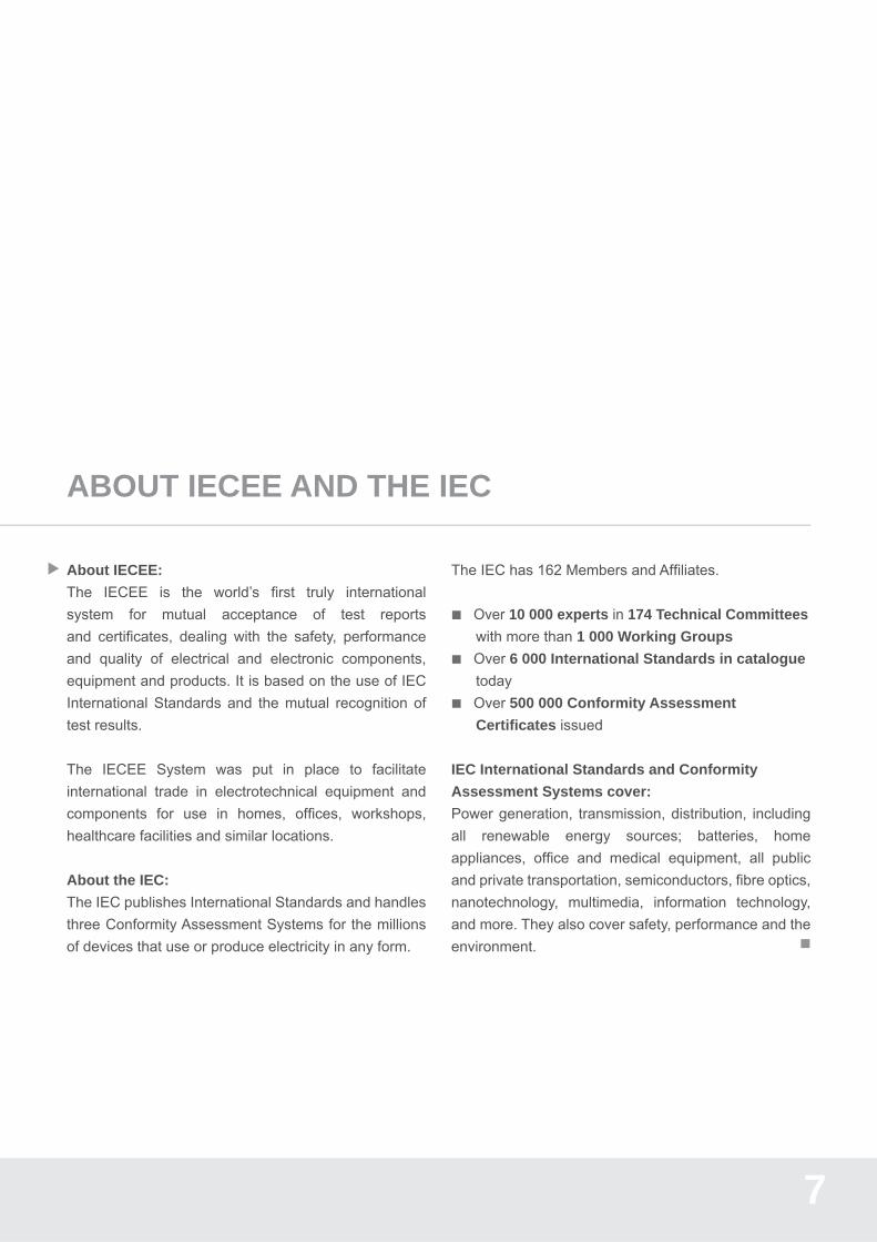
About IECEE:
The IECEE is the world’s fi rst truly international system for mutual acceptance of test reports and certifi cates, dealing with the safety, performance and quality of electrical and electronic components, equipment and products. It is based on the use of IEC International Standards and the mutual recognition of test results.
The IECEE System was put in place to facilitate international trade in electrotechnical equipment and components for use in homes, offi ces, workshops, healthcare facilities and similar locations.
About the IEC:
The IEC publishes International Standards and handles three Conformity Assessment Systems for the millions of devices that use or produce electricity in any form.
The IEC has 162 Members and Affi liates.
Over 10 000 experts in 174 Technical Committees with more than 1 000 Working Groups
Over 6 000 International Standards in catalogue today Over 500 000 Conformity Assessment
Certifi cates issued
IEC International Standards and Conformity
Assessment Systems cover: Power generation, transmission, distribution, including all renewable energy sources; batteries, home appliances, offi ce and medical equipment, all public and private transportation, semiconductors, fi bre optics, nanotechnology, multimedia, information technology, and more. They also cover safety, performance and the environment.
ABOUT IECEE AND THE IEC

2010
-07
® Registered trademark of the International Electrotechnical CommissionCopyright © IEC, Geneva, Switzerland. 2010.
INTERNATIONAL ELECTROTECHNICAL COMMISSION
3, rue de VarembéPO Box 131CH-1211 Geneva 20Switzerland
Tel: + 41 22 919 02 [email protected]
SYSTEM OF CONFORMITY ASSESSMENT SCHEMES FOR ELECTROTECHNICAL EQUIPMENT AND COMPONENTS (IECEE))
c/o IEC Central Offi ce3, rue de VarembéPO Box 131CH 1211 Geneva 20Switzerland
Tel: +41 22 919 02 [email protected]
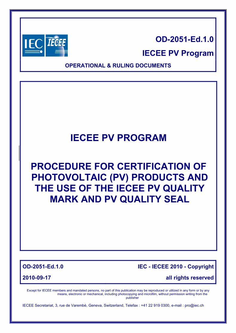
OD-2051-Ed.1.0
IECEE PV ProgramOPERATIONAL & RULING DOCUMENTS
IECEE PV PROGRAM
PROCEDURE FOR CERTIFICATION OF PHOTOVOLTAIC (PV) PRODUCTS AND THE USE OF THE IECEE PV QUALITY
MARK AND PV QUALITY SEAL
OD-2051-Ed.1.0 IEC - IECEE 2010 - Copyright
2010-09-17 all rights reserved
Except for IECEE members and mandated persons, no part of this publication may be reproduced or utilized in any form or by any means, electronic or mechanical, including photocopying and microfilm, without permission writing from the
publisher IECEE Secretariat, 3, rue de Varembé, Geneva, Switzerland, Telefax : +41 22 919 0300, e-mail : [email protected]

IEC System for Conformity Testing and Certification of Electrotechnical Equipment and Components
OD-2051-Ed.1.0 2/11 © IEC - IECEE 2010 2010-09-17
1.0 FOREWORD
The Global Approval Program for Photovoltaics (PV GAP) was established in 1998 under the auspices of an independent organization, PV GAP, to promote the use of international standards, quality management processes and organizational training in the manufacture, installation and sale of PV systems.
PV GAP established two certification marks for PV products, a PV Quality Mark for PV components and a PV Quality Seal for systems. The Mark and Seal are licensed to those companies and products which achieve approval under the PV GAP Program.
In 2007, PV GAP and the IECEE signed the first agreement that permitted the IECEE member NCBs to authorize the use of the PV GAP marks by manufacturers on their PV products. The agreement also provided a plan for the transfer of ownership of the PV GAP program and its marks to the IECEE.
The transfer of the ownership of the PV GAP Marks has been approved by the CMC in 2009, and has now been completed. The new owner (on behalf of the IECEE – which is not a legal entity), is Electrosuisse in Switzerland (which is a legal entity), which has registered the Marks with trademark authorities in Switzerland.
Each of the IECEE NCBs wishing to participate in the IECEE PV Program will be required to sign a ‘Mark Licence Agreement’ that will authorize the NCB to operate in this program and to grant PV product manufacturers the right to apply the PV Quality Mark or the PV Quality Seal, as appropriate, to their compliant products.
2.0 INTRODUCTION
2.1 This procedure defines the requirements for the Photovoltaic Mark and Seal Certification Program (PV Program) operated by the IECEE.
2.2 The primary objective of the PV Program is to facilitate direct market acceptance for PV products at the local level by local authorities, specifiers, retailers, distributors and users.
2.3 ISO 9000 Quality System Registration of the manufacturing location is a pre-requisite for the authorization to apply the PV Quality Mark and PV Quality Seal.
3.0 SCOPE 3.1 This procedure covers all IECEE PV Program activities that involve the authorization and
ongoing use of the IECEE PV Quality Mark or PV Quality Seal.
3.2 The PV Program utilizes the following IEC standards PV specifications:
60891, 60904, 61194, 61215, 61345, 61646, 61702, 61721, 61727, 61730, 61829, 62093, 62109, 62124, 62257, 62446, PVRS11A, PVRS11, PVRS6A, PVRS6

IEC System for Conformity Testing and Certification of Electrotechnical Equipment and Components
OD-2051-Ed.1.0 3/11 © IEC - IECEE 2010 2010-09-17
4.0 DEFINITIONS
PV Authorization Documentation A document package issued to confirm compliance with the PV Program requirements and to convey the right to use the PV Quality Mark or PV Quality Seal on conforming products. The document package consists of: - PV Certificate – CB-PV 101 - PV Compliance Report - CB-PV 102 - PV Test Report - Additional comments and observations - Initial or surveillance factory audit report - Documentation of the arrangements for ongoing factory inspection/surveillance PV Certificate - document issued by the NCB as part of the Authorization Documentation.
PV Quality Mark – a unique trademark (illustrated in Annex A1) for use with PV system components, registered on behalf of the IECEE by Electrosuisse (Switzerland), and licensed to IECEE NCBs by means of a PV Quality Mark and PV Quality Seal Licensing Agreement. The PV Quality Mark may be affixed only to Photovoltaic Components used in photovoltaic systems such as, for example, modules, regulators, inverters, batteries, switches, connectors, and materials.
PV Quality Seal – a unique trademark (illustrated in Annex A2) for use with PV systems, registered on behalf of the IECEE by Electrosuisse (Switzerland), and licensed to IECEE NCBs by means of a PV Quality Mark and PV Quality Seal Licensing Agreement. The PV Quality Seal should be affixed only to Photovoltaic “Systems”, such as, for example, photovoltaic home systems, street lights, or other systems powered by a PV module.
Unique identification number – Each participant is assigned its own unique identification number for use with the PV Quality Mark and PV Quality Seal. The full list of participants and their assigned ID numbers is available on the IECEE website. A NCB may also use its own name, trademark or brand name adjacent to the PV Quality Mark or PV Quality Seal.
PV Quality Mark and PV Quality Seal Licensing Agreement – A standardized legal agreement signed between Electrosuisse (Mark Owner) and each NCB participating in the PV Program, licensing the use of the PV Quality Mark and PV Quality Seal to the NCB.
PV Customer Service Agreement – A typical legal agreement (providing the minimum required content) signed between the NCB and the customer, authorizing the customer to apply the PV Quality Mark and PV Quality Seal on products and in locations that comply with the requirements of the IECEE PV Program.

IEC System for Conformity Testing and Certification of Electrotechnical Equipment and Components
OD-2051-Ed.1.0 4/11 © IEC - IECEE 2010 2010-09-17
5.0 RESPONSIBILITIES 5.1 Responsibilities of the NCB
The NCB is responsible for:
a) Signing the Mark Licensing Agreement with Electrosuisse, the registered “owner” of the PV Quality Mark and Seal;
b) Authorizing the use of the PV Quality Mark and/or Seal by the customer only where there is full compliance with the requirements of this program;
c) Executing a PV Customer Service Agreement with the customer to authorize the use of the PV Quality Mark and/or Seal under the specified conditions;
d) Providing an ongoing product inspection/surveillance program at the factory, in accordance with the requirements of this procedure, at each factory where the PV Quality Mark and/or Seal are applied;
e) Ensuring that its CBTLs participating in the PV Program have the IECEE recognition for the relevant standards, and are following the requirements of the Program;
f) Ensuring that all personnel involved in the PV Program at the NCB and the CBTL(s) are trained on an ongoing basis in:
- applicable IEC standards,
- IECEE operational procedures for the PV Program.
g) Reporting all issued Conformity Assessment Certificates to the IECEE Secretariat;
5.2 Responsibilities of the CBTL The CBTL is responsible for:
a) Following the requirements of the PV Program in relation to testing and documenting product compliance with the PV requirements;
b) Ensuring, in accordance with the NCB direction, that all personnel involved in the PV Program at the CBTL are trained on an ongoing basis in:
- applicable PV standards and specifications, and relevant testing practices,
- IECEE operational procedures for the PV GAP Mark program.

IEC System for Conformity Testing and Certification of Electrotechnical Equipment and Components
OD-2051-Ed.1.0 5/11 © IEC - IECEE 2010 2010-09-17
5.3 Responsibilities of the Customer (Manufacturer) The Customer is responsible for:
a) Maintaining a current ISO 9000 quality management system registration for each PV Program factory.
b) Signing a PV Customer Service Agreement with the NCB, pertaining to the application of the PV Quality Mark or PV Quality Seal.
c) Following the conditions specified in the PV Customer Service Agreement, including compliance with the relevant product standards and specifications, and the PV Program requirements.
6.0 NORMATIVE REFERENCES Document Number Title
ISO/IEC Guide 65:1996
General Requirements for Bodies Operating Certification Systems
ISO/ICE Guide 27:1983
Guidelines for corrective action to be taken by a certification body in the event of misuse of its mark of conformity
ISO/IEC 17025:2005 General Requirements for the Competence of Testing and Calibration Laboratories
ISO/IEC 17020:1998 General Criteria for the Operation of Various Types of Bodies Performing Inspections
IECEE 02 IECEE Rules of Procedure
Relevant IECEE Operating Documents
7.0 GENERAL PROVISIONS
7.1 The above references, define the general program requirements for NCBs and CBTLs operating under the PV Program.
7.2 PV products evaluated under the PV Program shall comply in full with the requirements of the applicable IEC standards and other documents accepted for use in the IECEE PV product category, as listed in Clause 3.2.
7.3 Each manufacturing location of PV products authorized to bear the PV Quality Mark or PV Quality Seal shall be covered by a valid ISO 9000 quality system registration.

IEC System for Conformity Testing and Certification of Electrotechnical Equipment and Components
OD-2051-Ed.1.0 6/11 © IEC - IECEE 2010 2010-09-17
8.0 ACCEPTANCE OF THE NCB 8.1 The NCB wishing to qualify for the PV Program shall be required to sign the PV Quality
Mark and PV Quality Seal Licensing Agreement with Electrosuisse.
8.2 Additionally, in countries that are not members of the WIPO “Madrid Agreement” on protection of trademarks, Electrosuisse may make the application for registration, and the cost of such an application would be borne in full by Electrosuisse.
Alternatively, a NCB in that country may be permitted to apply to the local trademark registration authorities for registration of the PV Quality Mark and PV Quality Seal.
A list of member countries of the Madrid Agreement is available on the IECEE Website in the PV area.
9.0 OPERATION 9.1 The application, evaluation and certification process that results in the issuance of PV
Authorization Documentation, is illustrated on the flowchart provided in Annex B.
9.2 The application for the PV Quality Mark or the PV Quality Seal begins with a manufacturer contacting the NCB and providing as a minimum the following information:
a) Letter formally requesting the PV GAP Mark License b) Details of the products c) Proposed usage of the PV Quality Mark or PV Quality Seal, e.g. on products, in
documentation, packaging and promotional material, as well as usage in catalogues and on a website;
d) Demonstration that the manufacturer’s quality management system includes appropriate measures to protect the marks, such as: i) A strict requirement that the Mark or Seal is only to be used on and
associated with “authorized” PV products; ii) Clear procedures for the development and release of promotional
material, including websites, to ensure the above requirement is followed; iii) Identification of the management personnel that has that this
responsibility and authority within the organization.
9.3 The NCB with its CBTL(s) will carry out a full evaluation of the product to the relevant requirements, in accordance with the IECEE procedures.
9.4 Additionally, the NCB will carry out an initial assessment of the applicant’s factory(ies) as
well as an assessment of the applicant’s procedures for compliance with the PV Program requirements.
9.5 On successful completion of the certification process, the NCB will issue the PV
Authorization Documentation including the certificate authorizing the customer to use of the PV Quality Mark or the PV Quality Seal on compliant products in specified factory locations that meet the requirements of the PV Program.
IEC System for Conformity Testing and Certification of Electrotechnical Equipment and Components
OD-2051-Ed.1.0 7/11 © IEC - IECEE 2010 2010-09-17
9.6 Use of the PV Quality Mark and PV Quality Seal
9.6.1 All reproductions of the PV Quality Mark and PV Quality Seal shall comply with the dimensional proportions as specified by the NCB authorizing the use of the PV Quality Mark or PV Quality Seal. The marks shall have a minimum size of 10 mm in height. The NCB identification number shall be placed as indicated in Annexes A1 and A2, with a minimum character size of 1mm in height.
9.6.2 The marks shall only be placed on products, or their documentation, packaging
and promotional material, which are covered by a valid PV Certificate and PV Compliance Report.
9.6.3 The Mark shall remain traceable at all times; the NCB identification number shall appear with the Mark or Seal, wherever it is used.
10.0 FACTORY INSPECTION/SURVEILLANCE 10.1 The NCB shall operate a documented factory inspection/surveillance program in
conformance with ISO/IEC 17020, to verify on an ongoing basis that the product and the factory comply with the requirements of the PV Program.
10.2 The minimum frequency of the factory inspections shall be once per year.
10.3 The factory inspection program shall include a procedure for corrective actions resulting from factory inspection/surveillance.
11.0 CORRECTIVE ACTIONS, SUSPENSIONS AND WITHDRAWAL OF CERTIFICATION
11.1 The NCB shall have procedures, in accordance with ISO/IEC Guide 27, to deal with misuses of the Mark, non-compliance with program requirements, non-compliance with product standards, defective products, etc., and to take appropriate corrective actions, including product re-work, removal of PV marks, as well as suspensions and cancellation of the PV Certificate and withdrawal of the authorization to use the PV marks.

IEC System for Conformity Testing and Certification of Electrotechnical Equipment and Components
OD-2051-Ed.1.0 8/11 © IEC - IECEE 2010 2010-09-17
12.0 DOCUMENTS AND RECORDS 12.1 All relevant records related to the testing, evaluation, certification and factory inspection
processes shall be maintained to ensure the integrity of the process and confidentiality of the information.
12.2 The records on each product shall be kept for as long as the product is certified and bears the PV Quality Mark or PV Quality Seal, and for 5 years after the withdrawal or cancellation of the certification.
13.0 DIRECTORY OF CERTIFIED PRODUCTS A Directory of Certified Products is provided on the IECEE Website. The NCBs
participating in the PV Program are required to provide appropriate information to the IECEE Secretariat.

IEC System for Conformity Testing and Certification of Electrotechnical Equipment and Components
OD-2051-Ed.1.0 9/11 © IEC - IECEE 2010 2010-09-17
ANNEX A1
THE PV QUALITY MARK
®
56
(Example of NCB Identification Number)
MC-001-07 (Example of User Identification)
PV Quality Mark – a unique trademark (illustrated in Annex A1) for use with PV system components, registered on behalf of the IECEE by Electrosuisse (Switzerland), and licensed to IECEE NCBs by means of a PV Quality Mark and PV Quality Seal Licensing Agreement. The PV Quality Mark may be affixed only to Photovoltaic Components used in photovoltaic systems such as, for example, modules, regulators, inverters, batteries, switches, connectors, and materials.
Unique identification number - Each participant is assigned its own unique identification number for use with the PV Quality Mark. The full list of participants and their assigned ID numbers is available on the IECEE website.
A NCB may also use its own name, trademark or brand name adjacent to the PV Quality Mark.

IEC System for Conformity Testing and Certification of Electrotechnical Equipment and Components
OD-2051-Ed.1.0 10/11 © IEC - IECEE 2010 2010-09-17
ANNEX A2
THE PV QUALITY SEAL
®
56 (Example of NCB Identification Number)
MC-001-07
(Example of User Identification)
PV Quality Seal – a unique trademark (illustrated in Annex A2) for use with PV “Systems”, registered on behalf of the IECEE by Electrosuisse (Switzerland), and licensed to IECEE NCBs by means of a PV Quality Mark and PV Quality Seal Licensing Agreement. The PV Quality Seal may be affixed only to Photovoltaic “Systems”, such as, for example, photovoltaic home systems, street lights, or other systems powered by a PV module.
Unique identification number - Each participant is assigned its own unique identification number for use with the PV Quality Seal. The full list of participants and their assigned ID numbers is available on the IECEE website.
A NCB may also use its own name, trademark or brand name adjacent to the PV Quality Seal.

IEC System for Conformity Testing and Certification of Electrotechnical Equipment and Components
OD-2051-Ed.1.0 11/11 © IEC - IECEE 2010 2010-09-17
ANNEX B
Certification Process Flowchart
Manufacturer provides application info to the NCB
Product is evaluated by NCB with its CBTL(s)
Assessment of applicant’s procedures by NCB
Initial factory assessment by NCB
Non-compliance is detected
Certification and issuance of the PV Certificate by the NCB
NCB addresses NCRs to manufacturerYes
No
Authorization for use of the Mark granted to manufacturer
and report to the IECEE
NCB operates aFactory Inspection Program
Annual report to IECEE on inspections carried out during
the year
NCB takes appropriate corrective actions if needed