inkjet printing of graphene - pure - aanmelden · inkjet printing of graphene kirill arapov,*a...
TRANSCRIPT
Inkjet printing of graphene
Arapov, Kirill A. Arapov; Abbel, R.J.; de With, G.; Friedrich, H.
Published in:Faraday Discussions
DOI:10.1039/C4FD00067F
Published: 01/01/2014
Document VersionPublisher’s PDF, also known as Version of Record (includes final page, issue and volume numbers)
Please check the document version of this publication:
• A submitted manuscript is the author's version of the article upon submission and before peer-review. There can be important differencesbetween the submitted version and the official published version of record. People interested in the research are advised to contact theauthor for the final version of the publication, or visit the DOI to the publisher's website.• The final author version and the galley proof are versions of the publication after peer review.• The final published version features the final layout of the paper including the volume, issue and page numbers.
Link to publication
Citation for published version (APA):Arapov, K., Abbel, R. J., With, de, G., & Friedrich, H. (2014). Inkjet printing of graphene. Faraday Discussions,173, 323-336. DOI: 10.1039/C4FD00067F
General rightsCopyright and moral rights for the publications made accessible in the public portal are retained by the authors and/or other copyright ownersand it is a condition of accessing publications that users recognise and abide by the legal requirements associated with these rights.
• Users may download and print one copy of any publication from the public portal for the purpose of private study or research. • You may not further distribute the material or use it for any profit-making activity or commercial gain • You may freely distribute the URL identifying the publication in the public portal ?
Take down policyIf you believe that this document breaches copyright please contact us providing details, and we will remove access to the work immediatelyand investigate your claim.
Download date: 12. Jun. 2018

Faraday DiscussionsCite this: Faraday Discuss., 2014, 173, 323
PAPER
Publ
ishe
d on
20
May
201
4. D
ownl
oade
d by
TE
CH
NIS
CH
E U
NIV
ER
SIT
EIT
EIN
DH
OV
EN
on
09/0
1/20
15 1
3:37
:01.
View Article OnlineView Journal | View Issue
Inkjet printing of graphene
Kirill Arapov,*a Robert Abbel,b Gijsbertus de Witha and Heiner Friedricha
Received 14th April 2014, Accepted 20th May 2014
DOI: 10.1039/c4fd00067f
The inkjet printing of graphene is a cost-effective, and versatile deposition technique for
both transparent and non-transparent conductive films. Printing graphene on paper is
aimed at low-end, high-volume applications, i.e., in electromagnetic shielding,
photovoltaics or, e.g., as a replacement for the metal in antennas of radio-frequency
identification devices, thereby improving their recyclability and biocompatibility. Here,
we present a comparison of two graphene inks, one prepared by the solubilization of
expanded graphite in the presence of a surface active polymer, and the other by
covalent graphene functionalization followed by redispersion in a solvent but without
a surfactant. The non-oxidative functionalization of graphite in the form of a donor-
type graphite intercalation compound was carried out by a Birch-type alkylation,
where graphene can be viewed as a macrocarbanion. To increase the amount of
functionalization we employed a graphite precursor with a high edge to bulk carbon
ratio, thus, allowing us to achieve up to six weight percent of functional groups.
The functionalized graphene can be readily dispersed at concentrations of up to
3 mg ml�1 in non-toxic organic solvents, and is colloidally stable for more than
2 months. The two inks are readily inkjet printable with good to satisfactory spreading.
Analysis of the sheet resistance of the deposited films demonstrated that the inks
based on expanded graphite outperform the functionalized graphene inks, possibly
due to the significantly larger graphene sheet size in the former, which minimizes the
number of sheet-to-sheet contacts along the conductive path. We found that the
sheet resistance of printed large-area films decreased with an increase of the number
of printed layers. Conductivity levels reached approximately 1–2 kU ,�1 for
15 printing passes, which roughly equals a film thickness of 800 nm for expanded
graphite based inks, and 2 MU ,�1 for 15 printing passes of functionalized graphene,
having a film thickness of 900 nm. Our results show that ink preparation and inkjet
printing of graphene-based inks is simple and efficient, and therefore has a high
potential to compete with other conductive ink formulations for large-area printing of
conductive films.
aLaboratory of Materials and Interface Chemistry, Dept. of Chemical Engineering and Chemistry, Eindhoven
University of Technology, Den Dolech 2, 5612AZ, Eindhoven, The Netherlands. E-mail: [email protected] Centre – TNO, High Tech Campus 31, 5656AE, Eindhoven, The Netherlands. E-mail: [email protected]
This journal is © The Royal Society of Chemistry 2014 Faraday Discuss., 2014, 173, 323–336 | 323
Faraday Discussions PaperPu
blis
hed
on 2
0 M
ay 2
014.
Dow
nloa
ded
by T
EC
HN
ISC
HE
UN
IVE
RSI
TE
IT E
IND
HO
VE
N o
n 09
/01/
2015
13:
37:0
1.
View Article Online
1 Introduction
Manufacturing large-area graphene thin lms is an important step towards thecommercialization of graphene based technologies. The inkjet printing of gra-phene is one method for the controlled deposition of large-area transparent ornon-transparent conductive lms.1–6 In comparison with other approaches suchas chemical vapor deposition (CVD),7,8 inkjet printing is a poor competitor. Thisholds true especially for transparent graphene thin lms,1,2 where high conduc-tivity and high transparency, together with precise control over the number oflayers and defect density is required. Nevertheless, the printing of graphene has avery high potential for applications, where non-transparent but highly conductivepatterns are required.9 Examples of such low-end, high-volume applications couldbe radio frequency identication tags (RFID tags), electromagnetic shielding, ordevices where graphene printing of conductive patterns can be effectively utilized.Graphene inks made from graphite have the potential to revolutionize the eld ofprinted conductors by replacing metallic inks while at the same time reducingbiological hazards and production costs.
There are several reports on graphene-based inks encompassing differentpreparation routes, including the oxidation of graphite to graphite oxide,1,2,10–12
and extended ultrasonication of graphite with3,13 or without a surfactant.6 Themajority of studies on non-oxidized graphene report a relatively low grapheneconcentration,2,6 poor conductivity2 and rather low ratio of graphene to surfac-tant.9 Recently, the successful non-oxidative functionalization of graphene wasshown, leading to slightly improved dispersibility in a number of solvents.14–16
Functionalization seems to be very promising for graphene inks as it allows theuse of surfactants for colloidal stabilization to be avoided, which in turn has beenmade responsible for decreasing the conductive properties of a printed layer byincreasing the sheet-to-sheet contact resistance. Unfortunately, the previouslydemonstrated amount of graphene functionalization and, thus, product dis-persibility, is far from ideal, a point which this paper will address.
In this paper we describe two methods for the preparation of graphene-basedinks. First, a simple, efficient and up-scalable method is presented, starting fromraw graphite and avoiding any oxidation steps to preserve the conductive prop-erties of the graphene throughout the entire process. Second, a non-oxidativecovalent functionalization of graphene is presented resulting in a nal productdispersibility of up to 3 mg ml�1 in non-toxic solvents. Subsequently we studiedthe printability of the two inks using two paper substrates, namely FS3 andLumiForte special application papers, which are widely used as substrates for theinkjet and screen printing of conductive patterns. Furthermore, the performanceof the two inks was evaluated by means of sheet resistance measurements of largeprinted areas as a function of the number of printed layers.
2 Experimental2.1 Preparation of expanded graphite (EG) from Li–THF–GIC
The synthesis of a ternary graphite intercalation compound with Li in THF (Li–THF–GIC) was performed using the procedure of Nomine and Bonnetain.17
Briey, 1.28 g of naphthalene C10H8 (0.01 mol, Alfa Aesar, USA) was dissolved in
324 | Faraday Discuss., 2014, 173, 323–336 This journal is © The Royal Society of Chemistry 2014

Paper Faraday DiscussionsPu
blis
hed
on 2
0 M
ay 2
014.
Dow
nloa
ded
by T
EC
HN
ISC
HE
UN
IVE
RSI
TE
IT E
IND
HO
VE
N o
n 09
/01/
2015
13:
37:0
1.
View Article Online
100 ml of freshly distilled tetrahydrofuran (THF) by vigorous stirring, followed bythe addition of 0.12 g of freshly cut metallic lithium (0.017 mol, Alfa Aesar, USA).Then 0.5 g of �10 mesh graphite (0.042 mol, Alfa Aesar, USA or Asbury Graphite,USA) was added to the reaction mixture at once. The reaction ask was thensealed and le stirring for another 72 hours. The Li–THF–GIC was separated fromthe side products by decantation followed by rinsing with freshly distilled THF.The residue was ltered and dried in ambient conditions for 20 minutes.
The freshly prepared GIC was placed at the bottom of a Vitreosil quartzcrucible ensuring that all of the particles were in mutual contact. The crucible wasplaced in a 2450 MHz 700 W home appliance microwave oven and exposed toirradiation for 1 minute. The as-prepared expanded graphite (EG) was usedwithout any further treatment.
2.2 EG ink preparation with Plasdone S-630
EG (1.4 mg ml�1) was added to a glass vial containing 5 mg ml�1 of a 60 : 40copolymer of N-vinyl-2-pyrrolidone and vinyl acetate (Plasdone S-630, AshlandInc., USA) dissolved in a mixture of isopropanol (IPA) and n-butanol (n-BuOH)with a volume ratio of 1 : 3. The slurry was ultrasonicated (Branson 1510DTH SB)in ice water for 30 minutes. The as-obtained dispersion was used without anyfurther treatment.
2.3 Functionalization of graphite platelet carbon nanobers (GCNFs)
The synthesis and functionalization of graphite via a potassium intercalationcompound (C8K GIC) were performed in a N2 glovebox with an O2 concentration<0.1 ppm and H2O <0.1 ppm.
Preparation of NaK. A liquid NaK alloy was prepared similarly to ref. 18. Briey,freshly cut and dry pieces of Na and K with a mass ratio of 1 : 7.4 were pressedtogether and agitated with a spatula to obtain a liquid state alloy.
Preparation of C8K GIC. Graphite platelet carbon nanobers (100 mg, 0.0083mol, Strem Chemicals, USA) were added to a 50 ml round bottom ask containing20ml of absolute THF, followed by the addition of 0.29ml of freshly prepared NaKalloy. The reaction mass was stirred for 3 days to obtain a dark blue to greendispersion. Next, 0.9 g of p-nitrobenzylbromide (0.00416 mol, Merck Chemicals,Germany) was dissolved in 10 ml of absolute THF and added to a GIC dispersionby 0.5 ml every 1.5 hours. Aer addition the reaction mixture was additionallyagitated for 1 day. Aerwards the sample was taken out of the glovebox, followedby quenching with isopropanol (5 ml), ethanol (5 ml), and nally water (5 ml). Thereaction mass was then centrifuged at 8000 rpm for 30 minutes and the super-natant was discarded. The product was redispersed in a THF–H2O (3 : 1) mixtureand centrifuged under the same conditions as described above. The washingprocedure was repeated with the following solvent mixtures: IPA–H2O (3 : 1),EtOH–H2O (3 : 1), EtOH–H2O (1 : 3), and H2O. The washed product was nallyredispersed in H2O and ltered through a 0.45 mm pore size PTFE membrane anddried under vacuum at 50 �C to yield a black powder of p-nitrobenzyl function-alized graphite platelet carbon nanobers (PNB–GCNFs). This material was usedfor the preparation of graphene inks without further treatment.
This journal is © The Royal Society of Chemistry 2014 Faraday Discuss., 2014, 173, 323–336 | 325

Faraday Discussions PaperPu
blis
hed
on 2
0 M
ay 2
014.
Dow
nloa
ded
by T
EC
HN
ISC
HE
UN
IVE
RSI
TE
IT E
IND
HO
VE
N o
n 09
/01/
2015
13:
37:0
1.
View Article Online
2.4 Ink preparation with PNB–GCNFs
PNB–GCNF powder (3 mg ml�1) was added to a vial containing propylene glycoldiacetate (PGDA, The Dow Chemical Company, USA) and ultrasonicated (Branson1510DTH SB) in ice water for 2.5 h. The as-prepared dispersion was used forprinting without further treatment.
2.5 Printing conditions
Printing tests were performed on a Dimatix DMP 2800 system (Dimatix-FujilmInc., USA), equipped with a 10 pl drop volume cartridge (DMC-11610). The printhead contained 16 parallel squared nozzles with a diameter of 30 mm. Thedispersion was printed at a voltage of 13 V, using a frequency of 5 kHz and acustomized waveform. FS3 paper (Felix Schoeller, Germany) and LumiForte paper(Stora Enso, Finland) were used as substrates. The distance between the printinghead and substrate was set to 200 mm. The following patterns were printed: dots (3lines, 200 mm drop spacing), rectangles of 5 � 35 mm in size, and 3 pixel widelines with a 20 mm line distance. In the case of the functionalized graphene inkswith propylene glycol diacetate as the solvent, the substrate temperature wasoptimized to 50 �C.
2.6 Thermal gravimetric analysis conditions
TGA measurements were performed using a TGA Q500 (TA Instruments, USA)in the temperature range 35–600 �C under a N2 gas ow with a heating rate of10 �C min�1.
2.7 X-ray photoelectron spectroscopy conditions
X-ray photoelectron spectroscopy (XPS) measurements were carried out with a K-Alpha, Thermo Scientic spectrometer using an aluminum anode (Al Ka¼ 1486.3eV) operating at 510 W with a background pressure of 8 � 10�8 mbar. The spectrawere recorded using the VGX900 data system collecting 40 scans. The spectra wereacquired at a take-off angle of 0� relative to the surface normal, corresponding to aprobe depth of around 10 nm.
2.8 X-ray diffraction conditions
X-ray diffractograms were obtained on a Bragg–Brentano Rigaku Geigerexdiffractometer with CuKa irradiation using Lindemann capillaries with aninternal diameter of 3 mm.
2.9 Sheet resistance measurement conditions
The sheet resistance wasmeasured with a four-point probe setup (source: Keithley237 High Voltage Measure Unit, resistance meter: Keithley 6517A High ResistanceMeter) with an interprobe distance of 5 mm, in a range of currents from 10 nA to1 mA.
326 | Faraday Discuss., 2014, 173, 323–336 This journal is © The Royal Society of Chemistry 2014

Paper Faraday DiscussionsPu
blis
hed
on 2
0 M
ay 2
014.
Dow
nloa
ded
by T
EC
HN
ISC
HE
UN
IVE
RSI
TE
IT E
IND
HO
VE
N o
n 09
/01/
2015
13:
37:0
1.
View Article Online
3 Results and discussion3.1 Preparation of ink with expanded graphite
The ink preparation workow starts with a donor-type intercalation of rawgraphite as shown in Fig. 1. The donor-type intercalation compound (IC) isformed by donating electrons to the graphite matrix, thus, making it negativelycharged, and accompanied by the insertion of positively charged species tosandwich a graphene layer between two layers of intercalants (stage 1 IC).18,19 Incontrast to oxidation, i.e., the withdrawal of electrons from a graphite matrix,such an approach prevents the formation of any functional groups, and hence,preserves the conductive properties of graphene. The formed stage 1 donor-typeIC slowly decomposes upon exposure to ambient conditions into mixtures of ahigher stage IC.20 For instance, the IC ake shown in Fig. 1b exhibits chargingeffects at the edges and planes which can be attributed to lithium salts dein-tercalating from the graphite matrix. Therefore, the intercalated materials wereanalyzed or used immediately aer their synthesis.
To increase the distance between graphene layers and to promote layer sepa-ration, the IC was subjected to high-speed thermal expansion by means ofmicrowave irradiation. Rapid heating of the GIC results in an abrupt conversionof the intercalated species into the gas phase, thus, causing expansion of thegraphite planes along the c-axis.21,22 The resulting expanded graphite (EG) has aporous worm-like structure, as shown in Fig. 1c, with a signicantly increasedspecic volume (more than 300 times larger compared to the initial IC). In thenext step, EG with concentrations of up to 1.4 mgml�1 was dispersed in a mixtureof i-propanol and n-butanol to obtain a colloidally stable dispersion (Fig. 1d). Forink formulation we opted for the highest graphene content vs. a reasonablecolloidal stability. We found experimentally that at a graphene concentration of1.4 mg ml�1 against 5 mg ml�1 of surfactant, the ink is colloidally stable for morethan 9 months, whilst also providing a maximum graphene to surfactant ratio.
Fig. 1 The preparation of graphene inks from raw graphite via intercalation. (a) The overallscheme showing: (i) graphite intercalation, (ii) thermal expansion, and (iii) liquid phaseexfoliation; (b) a scanning electron micrograph of a Li(THF) graphite intercalationcompound; (c) a scanning electron micrograph of expanded graphite; (d) a graphenedispersion with a concentration of 1.4 mg ml�1 prepared from expanded graphite.
This journal is © The Royal Society of Chemistry 2014 Faraday Discuss., 2014, 173, 323–336 | 327

Faraday Discussions PaperPu
blis
hed
on 2
0 M
ay 2
014.
Dow
nloa
ded
by T
EC
HN
ISC
HE
UN
IVE
RSI
TE
IT E
IND
HO
VE
N o
n 09
/01/
2015
13:
37:0
1.
View Article Online
3.2 Preparation of ink with functionalized graphene
As an alternative to the surfactant-based graphene ink formulation, we alsodeveloped a functionalized graphene ink (Fig. 2a). To date, there have beenseveral studies on graphene functionalization14,16,23,24 based on the chemistry ofdonor-type graphite intercalation compounds. Nevertheless, most approachesdemonstrate only a very low amount of functionalization (thus poor dis-persibility), which is in good agreement with the early works of Bergbreiter andKillough.25 According to ref. 25, in a donor-type IC the reactivities of edge and bulkcarbon atoms are different, with edge atoms undergoing the desired two-electronBirch-type alkylation, while bulk carbon can just give up an electron via a singleelectron transfer, thus acting as a catalyst for the undesired Wurtz-type coupling.This has led to the conclusion that the edge-to-plane ratio of carbon atoms plays asignicant role in functionalization efficiency. Therefore, instead of commonlyused micrometer-sized graphite, which has a low edge-to-plane carbon ratio, weused platelet-type, i.e. graphitic, carbon nanobers (GCNFs). This type ofgraphite, with graphene sheet sizes of only 10–60 nm, assures a high edge-to-plane carbon ratio (Fig. 2b).
According to the above concept, a high degree of functionalization cansignicantly improve the dispersibility of small sheet graphene due to anincreased number of interaction sites between functional groups and solventassociates. Thus, we synthesized a potassium graphite intercalation compoundwith GCNFs as the starting material for further functionalization. Next, wefunctionalized the as-obtained GCNF IC with p-nitrobenzylbromide using anapproach similar to the one described by Garst, Barbas, and Barton.26 In order tominimize the formation of undesired Wurtz-type dimerization side products, the
Fig. 2 Preparation of functionalized graphene inks from graphitic carbon nanofibers(GCNFs). (a) Scheme of GCNF functionalization (i) preparation of potassium–GCNF IC, (ii)functionalization of potassium–GCNF IC with p-nitrobenzylbromide, and (iii) liquid phaseexfoliation; (b) a transmission electron micrograph of the starting GCNF; (c) a transmissionelectron micrograph of the cast-dried functionalized GCNF; (d) a PNB–GCNF dispersionwith a concentration of 3 mg ml�1 in propylene glycol diacetate.
328 | Faraday Discuss., 2014, 173, 323–336 This journal is © The Royal Society of Chemistry 2014

Paper Faraday DiscussionsPu
blis
hed
on 2
0 M
ay 2
014.
Dow
nloa
ded
by T
EC
HN
ISC
HE
UN
IVE
RSI
TE
IT E
IND
HO
VE
N o
n 09
/01/
2015
13:
37:0
1.
View Article Online
concentration of alkyl radicals in solution had to be kept much lower than theconcentration of the substrate. Such conditions can be achieved by a slow alkyl-halide vapour diffusion into the reaction medium or, as utilized in our procedure,by the stepwise addition of a very dilute (see experimental) alkylhalide solution.Upon the addition of alkylhalide we observed a signicant volume expansion ofthe graphite phase indicating in situ exfoliation. The dried reaction product wasfound to be dispersible in a number of solvents including ethanol, i-propanol,chlorinated solvents and others. Transmission electronmicroscopy of a cast drieddispersion revealed that most of the GCNFs had been exfoliated into plateletswhich were prone to agglomeration, as shown in Fig. 2c.
We also performed dispersibility tests in order to nd an appropriate solventfor inkjet printing. Our criteria for the nal formulation included non-toxicity ofthe solvent, combined with a high solid content vs. colloidal stability, andprintability. Experimentally we found that an optimal solvent for p-nitrobenzylfunctionalized GCNFs (PNB–GCNFs) was propylene glycol diacetate (PGDA),allowing a solid content of 3 mg ml�1 without the use of surfactants (Fig. 2d).PGDA is a common solvent used for inkjet printing, with a viscosity of 2.6 mPa s(at 25 �C) and a surface tension of 32.9 mN m�1 (at 20 �C). The downside of thissolvent is the rather low relative evaporation rate of 0.04 (n-butyl acetate ¼ 1.0),which might extend the drying process.
3.3 Analysis of the functionalized graphene
The functionalized GCNF graphene was subjected to thermal gravimetric analysis(TGA). In an inert atmosphere this technique revealed (Fig. 3a) a sharp
Fig. 3 Analysis of p-nitrobenzyl functionalized carbon nanofibers. (a) Thermal gravimetricanalysis in dry N2 with a heating rate of 10 �C min�1; X-ray photoelectron spectra of (b) C1s, (c) N 1s, and (d) O 1s.
This journal is © The Royal Society of Chemistry 2014 Faraday Discuss., 2014, 173, 323–336 | 329

Faraday Discussions PaperPu
blis
hed
on 2
0 M
ay 2
014.
Dow
nloa
ded
by T
EC
HN
ISC
HE
UN
IVE
RSI
TE
IT E
IND
HO
VE
N o
n 09
/01/
2015
13:
37:0
1.
View Article Online
decomposition peak amounting to about 6 weight percent, which was attributedto the presence of functional groups (p-nitrobenzyl), relating to approximately oneper 166 carbon atoms. This hypothesis was supported by X-ray photoelectronspectroscopy (Fig. 3b–d). Here, XPS analysis conrmed the presence of carboncovalently bonded to a strong electron withdrawing group, i.e., C–NO2
(Fig. 3b).27,28 Further, XPS showed the presence of nitrogen, presumably in a nitrogroup (–NO2), as well as in reduced form –NHx (possibly including the hydrox-ylamine form), which can be explained by the partial reduction of nitro groups bythe NaK alloy (Fig. 3c).28,29 Also the XPS spectra of oxygen show the presence of astrong electron withdrawing oxygen containing group such as –NO2.28 Quanti-cation of the XPS data by peak area adjusted with relative sensitivity factors30 gavea relative carbon to nitrogen ratio of approximately 99 to 1. This corresponds to afunctionalization degree of one p-nitrobenzyl group per 92 carbon atoms ortheoretically 11 wt%. The observed discrepancy between the TGA and XPS datacan be attributed to several factors, such as probing depth, and the samplesurface roughness of the latter. Nevertheless, the results found by both tech-niques are comparable when the margins of error are taken into account.Considering all of the above results, combined with the signicantly improveddispersibility of the nal product, we concluded that functionalization had beensuccessful.
3.4 Inkjet printing of graphene-based inks onto paper substrates
Printing tests of the developed inks were performed on commercially availablepaper substrates, namely FS3 and Lumi. FS3 is a glossy, polymer-coated paper andLumi is a matt and rougher paper. The presence of a polymer coating on the FS3minimizes the surface roughness, making it similar to polymeric foil substratessuch as polyethylene terephthalate (PET), and it improves the adhesion of theprinted layers. Nevertheless, even with a coating on top, FS3 still maintained itsabsorbing properties towards solvents, and quickly separates the non-solublecomponents from soluble ones.
To analyze the spreading behavior of the inks, arrays of dots were printed. InFig. 4a–d optical micrographs of the corresponding shapes of the printed dots areshown. It can be clearly seen that, independent from the ink formulation, the twosubstrates have different spreading behavior. Dots printed on FS3 paper have around shape with sharp edges and no signicant signs of any “coffee stain” effectsare observed. Contrary to FS3, both of the inks printed on Lumi paper demon-strate extensive spreading with an increase in dot size. In addition, the printeddots have irregular shapes with ill-dened edges, thus signicantly lowering theresolution of the printed features. All of the above indicates clearly that inde-pendent from the ink formulation, both substrates have different spreadingproperties, with the FS3 paper suppressing any expansion of the droplet while it isdrying and adsorbing, whereas on the Lumi paper the droplet is spreading while itis drying or being absorbed.
An important characteristic of evaluating ink-substrate compatibility is theedge resolution and the ink spreading over large printing areas. To this end,rectangles of 5 � 35 mm in size were printed with 1, 5, 10 and 15 printing passeson both paper substrates. In Fig. 4e–l optical micrographs of the corners of theprinted rectangles are presented. The corners of the rectangles printed on FS3
330 | Faraday Discuss., 2014, 173, 323–336 This journal is © The Royal Society of Chemistry 2014

Fig. 4 Graphene based inks printed on FS3 (a, e, i and c, g, k) and Lumi (b, f, j and d, h, l)papers. Expanded graphite with Plasdone S-630 dots (a and b), and large-area rectangles(e, i and f, j), 10 printing passes. p-Nitrobenzyl functionalized graphene dots (c and d), andlarge-area rectangles (g, k and h, l), 10 printing passes. Scale bars: (a–d) – 20 mm, (e–l) –500 mm.
Paper Faraday DiscussionsPu
blis
hed
on 2
0 M
ay 2
014.
Dow
nloa
ded
by T
EC
HN
ISC
HE
UN
IVE
RSI
TE
IT E
IND
HO
VE
N o
n 09
/01/
2015
13:
37:0
1.
View Article Online
paper (Fig. 4e, g, i and k) have sharp edges in the printing direction andperpendicular to it, demonstrating a fair printing denition. In the case of EG +Plasdone S-630, it can be seen that the corners are rounded for the ink printed onLumi paper (Fig. 4f and j), which can be explained by extensive spreading of theink over the substrate. Overall the ink covered the substrate uniformly. Opticalmicrographs of the functionalized graphene ink printed on Lumi paper (Fig. 4hand l) also demonstrate a reasonable printing resolution, with a distinct edgeroughness, probably caused by the slow solvent evaporation and an increase ofthe Marangoni ow within a layer.
We found that ink spreading depends not only on the substrate but also on theink characteristics. The formulation based on expanded graphite with a polymericsurfactant printed on the FS3 substrate (Fig. 4e and i) demonstrated a goodspreading and uniform particle distribution. This ink was formulated with asolvent mixture of highly volatile i-propanol and n-butanol, that evaporatesquickly (evaporation rate of i-propanol ¼ 2.9, n-butanol ¼ 0.4, n-butyl acetate ¼1.0), thus, minimizing any particle segregation and producing a homogeneouslayer. For the same ink, a similar behavior was observed in the case of the Lumipaper (Fig. 4f and j), where the ink spreads rather uniformly with minimal dryingartefacts. The ink formulation based on functionalized graphene (PNB–GCNF)
This journal is © The Royal Society of Chemistry 2014 Faraday Discuss., 2014, 173, 323–336 | 331
Faraday Discussions PaperPu
blis
hed
on 2
0 M
ay 2
014.
Dow
nloa
ded
by T
EC
HN
ISC
HE
UN
IVE
RSI
TE
IT E
IND
HO
VE
N o
n 09
/01/
2015
13:
37:0
1.
View Article Online
printed on FS3 paper (Fig. 4g and k) demonstrated a non-uniform though regularparticle segregation into lines parallel to the printing direction. This behavior ismost likely caused by the slowly evaporating solvent and the ink's instability atlocally high concentrations. This creates a pattern where lines of segregatedmaterial are poorly connected with each other, potentially causing anisotropy ofthe conductive properties. The spreading of the PNB–GCNF ink on the Lumisubstrate (Fig. 4h and l) was very complex, with particle segregation not only alongthe printing direction but also perpendicular to it. This demonstrates thatextensive spreading in combination with slow drying decreases the printingresolution and overall printing quality.
3.5 Sheet resistance evaluation of inkjet printed graphene lms on papersubstrates
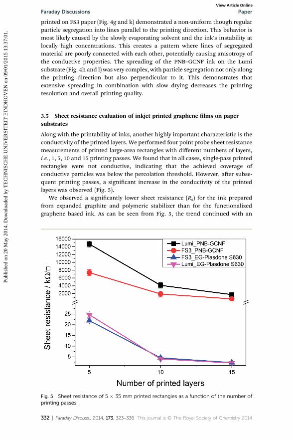
Along with the printability of inks, another highly important characteristic is theconductivity of the printed layers. We performed four point probe sheet resistancemeasurements of printed large-area rectangles with different numbers of layers,i.e., 1, 5, 10 and 15 printing passes. We found that in all cases, single-pass printedrectangles were not conductive, indicating that the achieved coverage ofconductive particles was below the percolation threshold. However, aer subse-quent printing passes, a signicant increase in the conductivity of the printedlayers was observed (Fig. 5).
We observed a signicantly lower sheet resistance (Rs) for the ink preparedfrom expanded graphite and polymeric stabilizer than for the functionalizedgraphene based ink. As can be seen from Fig. 5, the trend continued with an
Fig. 5 Sheet resistance of 5 � 35 mm printed rectangles as a function of the number ofprinting passes.
332 | Faraday Discuss., 2014, 173, 323–336 This journal is © The Royal Society of Chemistry 2014

Paper Faraday DiscussionsPu
blis
hed
on 2
0 M
ay 2
014.
Dow
nloa
ded
by T
EC
HN
ISC
HE
UN
IVE
RSI
TE
IT E
IND
HO
VE
N o
n 09
/01/
2015
13:
37:0
1.
View Article Online
increase in the number of printing passes for both inks resulting in decreasingsheet resistance. This results, for 15 printing passes, in a lm sheet resistance ofapproximately 1–2 kU ,�1 for the EG + Plasdone S-630 ink (800 nm thickness)and �2 MU ,�1 for the PNB–GCNF ink (900 nm thickness). Remarkably, in thecase of EG with Plasdone S-630, we did not notice any signicant difference in Rs
for the two paper substrates, which is in good agreement with the observedspreading of the ink (Fig. 4e, i and f, j). However, we found a signicant (�2 times)difference in Rs for the PNB–GCNF ink, which correlates with the difference inspreading and drying of the ink (Fig. 4g, k and h, l) described earlier. Thus, inkjetprinted lms with uniformmaterial distribution demonstrate lower and isotropicsheet resistance, whilst printed lms with a non-uniform particle distributionshow higher and anisotropic sheet resistance.
From the observed sheet resistance data we hypothesize that the size of thegraphene sheets plays a role in the conductive properties. If we assume that the Rs
of a graphene lm scales with the resistance of the contact between two akes(R(CR)) and the resistance of the graphene ake itself (R(GF)), then the number ofcontacts would give a major contribution to the overall resistance. Here weassume that Rs for a ake is approximately constant for all sizes as it depends onthe defect density,31–33 or doping,34–40 etc. Since the large (90% of population >1mm) graphene akes of EG + Plasdone S-630 assemble into a layer with fewercontacts between each other compared to a layer of the PNB–GCNF graphene(90% of population <60 nm), then the overall sheet resistance of the former lm(on both substrates) is much lower than that of the latter.
4 Conclusions
In this paper we demonstrated two approaches for graphene ink formulation:rst, based on the solubilization of graphene with a surface active polymer, and,second, based on covalent graphene functionalization. In the rst route, we useda donor-type graphite intercalation compound as an intermediate prior tothermal expansion to avoid any oxidation of the graphene. We experimentallyfound that the presence of a surface active polymer (60 : 40 copolymer of N-vinyl-2-pyrrolidone and vinyl acetate, Plasdone S-630) facilitated efficient grapheneexfoliation allowing stable colloidal dispersions with concentrations of up to 1.4mg ml�1 at a polymer concentration of 5 mg ml�1 in a mixture of non-toxicsolvents. The formulated ink was printable on substrates including plastic foilsand paper.
In the second route, we synthesized a potassium graphite intercalationcompound with graphitic carbon nanobers as a precursor and utilized it as anintermediate for covalent functionalization. We conrmed the hypothesis thathigh ratios between edge and bulk carbon atoms would increase the Birch-typealkylation efficiency with p-nitrobenzylbromide, allowing up to six weight percentof functional moieties. The functionalized graphene was readily dispersible in anumber of solvents at high concentrations including alcohols, ethers, and chlo-rinated solvents. We found that the optimal solvent was propylene glycol diac-etate, which can disperse up to 3 mg ml�1 of solid material with a colloidalstability of up to several months.
Both inks were printable on FS3 and Lumi paper substrates with good tosatisfactory spreading. From our observations of spreading and drying behavior,
This journal is © The Royal Society of Chemistry 2014 Faraday Discuss., 2014, 173, 323–336 | 333

Faraday Discussions PaperPu
blis
hed
on 2
0 M
ay 2
014.
Dow
nloa
ded
by T
EC
HN
ISC
HE
UN
IVE
RSI
TE
IT E
IND
HO
VE
N o
n 09
/01/
2015
13:
37:0
1.
View Article Online
we concluded that the optimal combination is an ink of expanded graphite withPlasdone S-630 printed on FS3 paper, as the ink forms a uniform layer with areasonable print resolution. Further, we analyzed the conductive properties of theinks by measuring the sheet resistance of large-area printed rectangles. Theevaluation of sheet resistance as a function of the number of printing passesshowed a signicant (up to 2000 times) difference between the two inks in favor ofthe one containing expanded graphite. We hypothesize that this difference couldbe due to a much smaller number of sheet-to-sheet contacts, and that the overallresistance mainly depends on the resistance of the graphene itself. In contrast tothat, for a functionalized graphene printed lm, the number of sheet-to-sheetcontacts is much larger, therefore, the resistance of the lm is limited by inter-layer contact resistance. Such a hypothesis is a task for further investigation.Finally, we found that the sheet resistance decreases with an increase of thenumber of printing passes, providing the opportunity that further increasing theprinted layer thickness could lower the sheet resistance to reach the conductionvalues achieved by metal based inks. Taking into account the simplicity and cost-effectiveness of our method, we believe that inkjet printing of graphene basedinks is a good alternative for the mass production of conductive lms and deviceson paper.
Acknowledgements
The research leading to these results has received funding from the EuropeanUnion Seventh Framework Programme (FP7-MC-ITN) under grant agreement no.264710. The authors would like to thank the Directorate-General for Science,Research and Development of the European Commission for nancial support ofthe research. Authors would like to acknowledge Corne Rentrop (TNO, Eind-hoven, The Netherlands) for providing paper for the experiment and valuablecomments to the nal version of the manuscript.
References
1 L. Huang, Y. Huang, J. Liang, X. Wan and Y. Chen, Nano Res., 2011, 4, 675–684.2 J. Li, F. Ye, S. Vaziri, M. Muhammed, M. C. Lemme and M. Ostling, Adv. Mater.,2013, 25, 3985–3992.
3 S. Lim, B. Kang, D. Kwak, W. H. Lee, J. A. Lim and K. Cho, J. Phys. Chem. C,2012, 116, 7520–7525.
4 E. B. Secor, P. L. Prabhumirashi, K. Puntambekar, M. L. Geier andM. C. Hersam, J. Phys. Chem. Lett., 2013, 4, 1347–1351.
5 Y. Su, J. Du, D. Sun, C. Liu and H. Cheng, Nano Res., 2013, 6, 842–852.6 F. Torrisi, T. Hasan, W. Wu, Z. Sun, A. Lombardo, T. S. Kulmala, G. W. Hsieh,S. Jung, F. Bonaccorso, P. J. Paul, D. Chu and A. C. Ferrari, ACS Nano, 2012, 6,2992–3006.
7 X. Li, Y. Zhu, W. Cai, M. Borysiak, B. Han, D. Chen, R. D. Piner, L. Colombo andR. S. Ruoff, Nano Lett., 2009, 9, 4359–4363.
8 A. Reina, X. Jia, J. Ho, D. Nezich, H. Son, V. Bulovic, M. S. Dresselhaus andJ. Kong, Nano Lett., 2009, 9, 30–35.
9 J. M. Crain, J. S. Lettow, I. A. Askay, S. A. Korkut, K. S. Chiang, C.-H. Chen,R. K. Prud’homme, USA Pat., # 8,278,757, 2012.
334 | Faraday Discuss., 2014, 173, 323–336 This journal is © The Royal Society of Chemistry 2014

Paper Faraday DiscussionsPu
blis
hed
on 2
0 M
ay 2
014.
Dow
nloa
ded
by T
EC
HN
ISC
HE
UN
IVE
RSI
TE
IT E
IND
HO
VE
N o
n 09
/01/
2015
13:
37:0
1.
View Article Online
10 V. Dua, S. P. Surwade, S. Ammu, S. R. Agnihotra, S. Jain, K. E. Roberts, S. Park,R. S. Ruoff and S. K. Manohar, Angew. Chem., Int. Ed., 2010, 49, 2154–2157.
11 L. T. Le, M. H. Ervin, H. Qiu, B. E. Fuchs and W. Y. Lee, Electrochem. Commun.,2011, 13, 355–358.
12 L. T. Le, M. H. Ervin, H. Qiu, B. E. Fuchs, J. Zunino and W. Y. Lee, IEEE NANO2011, Portland, OR, 2011.
13 H. Zhang, A. Xie, Y. Shen, L. Qiu and X. Tian, Phys. Chem. Chem. Phys., 2012,14, 12757–12763.
14 J. M. Englert, K. C. Knirsch, C. Dotzer, B. Butz, F. Hauke, E. Spiecker andA. Hirsch, Chem. Commun., 2012, 48, 5025–5027.
15 L. H. Liu, M. M. Lerner and M. Yan, Nano Lett., 2010, 10, 3754–3756.16 B. Genorio, W. Lu, A. M. Dimiev, Y. Zhu, A. R. Raji, B. Novosel, L. B. Alemany
and J. M. Tour, ACS Nano, 2012, 6, 4231–4240.17 M. Nomine and L. Bonnetain, J. Chim. Phys. Phys.-Chim. Biol., 1969, 66, 1731–
1741.18 L. M. Viculis, J. J. Mack, O. M. Mayer, H. T. Hahn and R. B. Kaner, J. Mater.
Chem., 2005, 15, 974.19 M. S. Dresselhaus and G. Dresselhaus, Adv. Phys., 2002, 51, 1–186.20 M. Inagaki and O. Tanaike, Carbon, 2001, 39, 1083–1090.21 Y. W. Zhu, S. Murali, M. D. Stoller, A. Velamakanni, R. D. Piner and R. S. Ruoff,
Carbon, 2010, 48, 2118–2122.22 S. Jin, L.-S. Xie, Y.-L. Ma, J.-J. Han, Z. Xia, G.-X. Zhang, S.-M. Dong and
Y.-Y. Wang, J. Phys.: Conf. Ser., 2009, 188, 012040.23 S. Chakraborty, J. Chattopadhyay, W. Guo andW. E. Billups, Angew. Chem., Int.
Ed., 2007, 46, 4486–4488.24 J. M. Englert, C. Dotzer, G. Yang, M. Schmid, C. Papp, J. M. Gottfried,
H. P. Steinruck, E. Spiecker, F. Hauke and A. Hirsch, Nat. Chem., 2011, 3,279–286.
25 D. E. Bergbreiter and J. M. Killough, J. Am. Chem. Soc., 1978, 100, 2126–2134.26 J. F. Garst, J. T. Barbas and F. E. Barton, J. Am. Chem. Soc., 1968, 90, 7159–7160.27 E. Bekyarova, S. Sarkar, S. Niyogi, M. E. Itkis and R. C. Haddon, J. Phys. D: Appl.
Phys., 2012, 45, 154009.28 A. K. Haridas, C. S. Sharma, V. Sritharan and T. N. Rao, RSC Adv., 2014, 4,
12188.29 G. Yang, H. Hu, Y. Zhou, Y. Hu, H. Huang, F. Nie and W. Shi, Sci. Rep., 2012, 2,
698.30 C. D. Wagner, L. E. Davis, M. V. Zeller, J. A. Taylor, R. H. Raymond and
L. H. Gale, Surf. Interface Anal., 1981, 3, 211–225.31 J.-H. Chen, W. Cullen, C. Jang, M. Fuhrer and E. Williams, Phys. Rev. Lett.,
2009, 102, 236805.32 K. W. Clark, X. G. Zhang, I. V. Vlassiouk, G. He, R. M. Feenstra and A. P. Li, ACS
Nano, 2013, 7, 7956–7966.33 A. Lherbier, S. M. M. Dubois, X. Declerck, S. Roche, Y.-M. Niquet and
J.-C. Charlier, Phys. Rev. Lett., 2011, 106, 046803.34 A. Benayad, H. J. Shin, H. K. Park, S. M. Yoon, K. K. Kim, M. H. Jin, H. K. Jeong,
J. C. Lee, J. Y. Choi and Y. H. Lee, Chem. Phys. Lett., 2009, 475, 91–95.35 A. Kasry, M. A. Kuroda, G. J. Martyna, G. S. Tulevski and A. A. Bol, ACS Nano,
2010, 4, 3839–3844.
This journal is © The Royal Society of Chemistry 2014 Faraday Discuss., 2014, 173, 323–336 | 335

Faraday Discussions PaperPu
blis
hed
on 2
0 M
ay 2
014.
Dow
nloa
ded
by T
EC
HN
ISC
HE
UN
IVE
RSI
TE
IT E
IND
HO
VE
N o
n 09
/01/
2015
13:
37:0
1.
View Article Online
36 K. K. Kim, A. Reina, Y. Shi, H. Park, L. J. Li, Y. H. Lee and J. Kong,Nanotechnology, 2010, 21, 285205.
37 T. Kobayashi, M. Bando, N. Kimura, K. Shimizu, K. Kadono, N. Umezu,K. Miyahara, S. Hayazaki, S. Nagai, Y. Mizuguchi, Y. Murakami andD. Hobara, Appl. Phys. Lett., 2013, 102, 023112.
38 H. Mousavi and R. Moradian, Solid State Sci., 2011, 13, 1459–1464.39 Y. J. Ren, S. S. Chen, W. W. Cai, Y. W. Zhu, C. F. Zhu and R. S. Ruoff, Appl. Phys.
Lett., 2010, 97, 053107.40 S. Tongay, K. Berke, M. Lemaitre, Z. Nasrollahi, D. B. Tanner, A. F. Hebard and
B. R. Appleton, Nanotechnology, 2011, 22, 425701.
336 | Faraday Discuss., 2014, 173, 323–336 This journal is © The Royal Society of Chemistry 2014