information for site use - mitek uk and ireland · during erection to ensure that trusses are...
TRANSCRIPT

49
Section3.0
Modifying Trussed Rafters on Site
The basis rule here is DO NOT MODIFY TRUSSED RAFTERS on site unless the prior permission for the
modification is obtained from the Trussed Rafter Designer.
Trussed rafters are designed for a purpose and should never be cut, notched, drilled or otherwise modified
without full consideration of the resultant effect.
If for some reason an adjustment in the geometry or internal structure of the truss is required by the site,
REFER BACK to the Trussed Rafter Fabricator. He will have the engineering design for the units supplied
and is in the ideal position to co-ordinate any action which may be needed.
Informationfor Site Use

Section
3.1Information for Site Use
50
Do's and Don'ts on SiteSite storageBearers should be placed on a level, hard and dry
surface. A waterproof covering must be used to
protect components against rain and sun and to allow
good air circulation. In vertical storage, bearers must
be high enough to keep rafter overhangs clear of the
ground. In horizontal storage, bearers must be
arranged at close centres to give level support.
Fit it rightFixing problems are eliminated in roof construction
by the use of proprietory Builder Products.
Proprietory joist hangers, restraint straps, connector
plates, framing anchors, truss clips and shoes save
time, money and produce a quality job. Your MiTek
fabricator will advise you as to the right products for
the job.
Think don't cutTrussed rafters are designed and fabricated for a
particular purpose - and to save work. Trusses must
not be cut under any circumstance. Truss spacings
can usually be adjusted to take hatch openings and
chimney breasts. For large chimney breasts, trusses
are specially designed and supported.
Don't cut or guess, consult your trussed rafter
supplier if you are in doubt.
HandlingCare in the handling trusses must be taken at all
times. 'See-sawing' trusses on walls or scaffolding
must be avoided and where necessary an extra man
should be used to prevent the truss being distorted.
Large trusses handled mechanically should be
adequately supported.
BracingThe Building Designer will have detailed the
permanent roof bracing. Permanent roof bracing is
required to ensure the stability of the roof. Each roof
requires longitudinal and diagonal bracing. In
specific cases bracing is also required to stabilise
long web members. Temporary bracing must be fixed
during erection to ensure that trusses are maintained
in a vertical plane.
Support your tankThe extra load of a water tank requires careful
support. Additional trimmers across the joists
support the bearers.
DO STORE ON DO HANDLE WITH DO FIX ITSITE CAREFULLY CARE RIGHT
TRUSSES DO NEED DON'T CUT DO SUPPORTBRACING YOUR TANK
IF IN DOUBT - ASK!

Information for Site Use
51
Section3.2
Supporting Water Tanks
Water tank support for standard Fink Trusses
Water tank support platform
Figure 68
Figure 69
Figure 68Tank support to be as
Detail A or B (See page 54)
Truss spacings shown are based on
a maximum module of 600mm c/c
Tank placed centrally
Ties and bracing omitted for clarity
Node point
Node point
Bearer 'a' placed as close to
node point as possible
Tank support to be as
Detail A or B (See page 54)
46 x 97mm minimum
sole plate tight to node
point and securely
nailed to trusses
Tank placed centrally
Note: Always carefully brace elevated tank
platforms back to main truss
25 x 100mm bracingStuds notched to fully
support bearer 'a'
Span of trusses Ls
Span of trusses LsBay size
Bay size

Section
3.2Information for Site Use
52
Supporting Water TanksWater tank support for Mono Pitch Trusses
Water tank support platform for Mono Pitch Trusses
Figure 70
Figure 71
Tank support to be as Detail
A or B (see page 54)
Tank support to be as Detail
A or B (see page 54)
Standard mono pitched truss
as main roof
xDo no fix to diagonal web
unless truss has been
designed to carry the load
Bay size
Mono pitched trusses with
reversed internal members
Node point
Bearer 'a' placed as close
to node point as possible
If mono pitch trusses are
supported on wall as
shown then a pack will
be required under
bearer 'b'
Alternatively
If supported at the wall
face on hangers then the
bearer 'b' should be
built into wall 100mm
Mono truss configuration has
limited space for a water tank
unless of a reasonably high
pitch. Alternatively member 'X'
can be reversed as shown in the
above illustration
Bearer 'a' securely nailed to
truss verticals
50mm x truss width bearers
securely nailed to truss
verticals to support bearers 'a'
A minimum of 25mm should be left between
bearer 'c' and the truss ceiling member to
allow for long term deflection

Information for Site Use
53
Section3.2
Supporting Water TanksWater tank support for Small Span Trusses
Water tank support for Open Plan Attic Trusses
Figure 70
Figure 70
Tank support to be as Detail
A or B (see page 54)
Tank placed centrally
Ridgeboard support
ledger (Nailed to
multiple girder truss)
Standard truss to main roof
Infill rafters
(to be
minimum
25mm deeper
than trussed
rafter member
to allow for
birdsmouthing
at wallplate
Bay size(2.0m Max)
Compound bearer and
binder 'a' placed as close to
note point as possible
Infill ceiling joist 1.8mm Max
Bearer 'a' placed as
close to node point
as possible
High level water tank support
Alternative support positions
Low level water
tank support
Packs
Bay size
Bay size
Tank support to be as Detail
A or B (see page 54)
A minimum of 25mm should be left between
bearer 'c' and the truss member to allow
for long term deflection

Section
3.2Information for Site Use
54
Supporting Water TanksDetail 'A' Detail 'C'
Table 1: Sizes for support memberTank capacity to marked Minimum member size (mm) Max span Ls for fink trussed Max bay size for other
water line a and c b rafters (m) configurations (m)
Detail 'A' not more than 300 47 x 72 2/35 x 97 or 6.50 2.20
litres on 4 trussed rafters 1/47 x 120
47 x 72 2/35 x 120 or 9.00 2.80
1/47 x 145
47 x 72 2/35 x 145 12.00 3.80
Detail 'B' not more than 230 47 x 72 1/47 x 97 6.50 2.20
litres on 3 trussed rafters 47 x 72 2/35 x 97 or 9.00 2.80
1/47 x 120
47 x 72 2/35 x 120 or 12.00 3.80
1/47 x 145
Detail 'C' not more than 300 1/72 x 145 or 1/72 x 145 or 6.00 2.00
litres on 2 multiple trusses 2/35 x 145 2/35 x 145
as shown
Figure 74
Figure 75
Figure 76
Detail 'B'
If water tanks are to be supported
on the trussed rafters in accordance
with the details shown then the
provision for these must be taken
into account at the design stage.
Otherwise, the additional loads
imposed by the water tanks must be
supported independent of the
trussed rafters.
Where space is limited this detail may be used between members a & b and b& c in
order to gain head room. However a minimum clearance of 25mm above the ceiling
lining or truss member must be allowed for possible long term deflection.
Note: Support members may be of any species with a permissible bending stress not less than that of European redwood/whitewood of C16
strength class or better.
Longitudinal ties to be offset to clear
tank bearers and placed as close to
node point as possible
Longitudinal ties to be offset to clear
tank bearers and placed as close to
node point as possible
Lap joint to be over
2 No trusses
S=trussed rafter
spacing max 600mm c/c
Node point
Node point
Node point
Bay size 2m max
Joist hanger
Min 25mm
Alternative support
between members
for detail ‘A’ & ‘B’

Information for Site Use
55
Section3.3
Hatch and Chimney openingsWhere possible, hatches and chimneys should be
accommodated in the standard spacing between
trusses.
Each member and joint in a truss performs an
important role, essential to the effective functioning of
all other parts and the component as a whole. Trusses
must never be cut and trimmed except according to
details supplied by the Trussed Rafter Designer.
The principle behind the methods and details given in
this section is to ensure that no individual trussed rafter
is subject to a load significantly greater than that
applied, were it at standard spacing.
Figure 77a shows a system suitable for openings
greater than 10% over standard and up to twice
standard spacing. Battens and plasterboard should be
given extra support.
Support of the loose timbers is provided in line with
each truss joint by a purlin, binder or ridge board and
by trimmers at the actual opening.
When the two trimming trusses at each side of the
opening (figure 77b) are actually nominally fixed
together with nails, at say 600mm centres along all
members, an opening of up to three standard spacings
may be used. Deeper purlins, binders and ridge board
of typically 47 x 175mm and trimmers of 47 x 125mm
should be installed.
Depending on the design of the chimney flue and
stack, appropriate clearance should be allowed
between timber and chimney.
Figure 77a
Figure 77c
Figure 77b
Figure 77b
Although intended primarily for trussed
rafters, the above principles can also be
used for framing with Attic Frames.
Raised Tie or Extended joist trusses
require careful consideration when
framing around hatch or chimney
openings, as often reinforcing timbers
(Scabs) are already required on the
'standard' unit and it is often not possible
to design multiple ply units of this type.
S
S
B
C
B
S
S
S SC up to 3S
B
AA
BC up to 2S
Trimmer Ridgeboard
Loose rafter deeper than trusses
birdsmouthed onto wallplate
and purlin Ridgeboard
CollarLedger supportingridge board of trusses
PurlinTrimmer
Trimmer Trimmer
S = Standard spacing
C = Chimney opening
B = Reduced spacing
A = Effective spacing

Section
3.4Information for Site Use
56
Two Tier ConstructionIt is necessary to use two tier trussed rafters when the
vertical dimension of a single component would be
too large for manufacturing or transportation. This
dimension is generally 3.9 - 4.4m but your MiTek
fabricator will advise you when to expect trusses in
this form.
The two tier truss (figure 78) comprises a flat-topped
base truss and a triangular capping truss, fitting
alongside the base truss on longitudinal bearers.
Each truss may be one of a large selection of types.
The base truss will generally be made as high as
practical but not so high that the span of the capping
truss is less than 2-3m. Although a duo-pitched shape
is shown in figure 78, all basic configurations can be
constructed by the two tier method.
The bracing of the flat top chord of the base truss is
important in ensuring its performance in
compression.
The base trusses should be erected, full permanent
bracing installed and battens fixed, up to the top
position of the capping trusses. The resulting
structure then forms a safe, rigid working platform
for the erection of the capping trusses. Tiling or
loading of the base trusses should not proceed until
the capping trusses are fully installed and braced.
Figure 78
Figure 79a
Figure 79d
Figure 79c
Figure 79b
Capping truss
Capping truss
Capping trusses
Minimum 38 x 75
ledger
Splice. N.B. Not in line
with other edge of base
truss
Flat top chord of base
trusses25 x 100
brace
47/50 x 100
bearer
25 x 100
braceBase trusses
Base trusses
minimum 47/50 x
100 bearer
Minimum 6
3.75 x 65mm
galvanised
round wire nails
Base truss
50 x 100 bearers
continuous for
length of roof
(see fig79b)
25 x 100 braces
at 600mm centres
(see fig79c)
400 to 500mm
rafter overlap
(see fig79a)
Cap
Often the cap truss sits in the same
plane as the base truss and they are
connected together using a MiTek
Field Splice plate
Field splice plate pressed into
one part in factory and nailed
in other part on site
Base

Information for Site Use
57
Section3.5
Hip Ends and CornersTypical Roof Features - Hipped EndsThe most common end shapes are the Gable End,
which allows the simplest roof framing and uses
most support wall surface; the Hipped End which
offers a simple wall solution at the expense of a more
complex roof structure, and the Dutch Hip and Gable
Hip, which are compromises between a gable and
hip, easily formed using trussed rafters.
Most traditional hipped ends behave like an inverted
conical basket and, under load, the tendency for its
rim (the wall plate) to spread is resisted by friction
(lateral force on the wall), tension in the rim (tension
and bending in the wall plate) and tension in the weft
(the tiling battens). In the long term the results are
sagging hip boards and rafters, bulging walls and
characteristic horizontal cracks in the masonry at the
inside corners of the dwellings roughly 300-600mm
below ceiling level.
However, hipped end systems develop by MiTek do
not depend on tension in battens, or a massive
wallplate and horizontal resistance from the walls.
With suitable bracing, the trussed rafter hip roof
provides the walls with the stability required by
Building Regulations.
Figure 36a Figure 36b
Figure 36dFigure 36c
Figure 37a
Gable end
Dutch Hip
Action of hip end
Traditional hipped end
Gable Hip
Hipped end
Figure 37b

Section
3.5Information for Site Use
58
Hip Ends and CornersHipped EndsThe simplest form of hipped end consists of a multi-
ply girder of standard trusses securely nailed or
bolted together, which support loose rafters and
ceiling joists, as in figure 38.
This is the most inexpensive form of hip because no
special trusses are needed other than the girder, but
their use is limited to spans up to 5m.
Loose rafter and ceiling joist sizes should be taken
from Approved Document A to the Building
Regulations. Hip boards should be supported off the
girder by means of a ledger. The ceiling joists should
be supported by proprietory joist hangers.
If the end pitch is different to the pitch of the main
roof, the eaves details should be discussed with your
trussed rafter supplier. It is advisable to ensure that
the top extremities of rafter overhangs are at the
same level to provide for continuous guttering. Note
that whilst adjustments can be dealt with on site in
loose timber construction, the mono-pitched trusses
used in other hip types must be made correctly in the
factory.
It should also be noted that all forms of hip
construction employing a hip board exerts a
horizontal thrust at the wallplate corner junction.
Having taken up any horizontal movement, of
course, the structure becomes stable. Movement of
the wallplate can be controlled by fixing a 1200mm
length of galvanised steel restraint strap around the
outside. See figure 41.
MiTek trussed rafter suppliers can provide detailed
advice on hipped end roof details.
Figure 38
Figure 40
Figure 41
Figure 39
Simple hip end
LEDGER DETAILS Multi-ply girder
Minimum 38 x 100 ledger
Multi-ply girder
Hip boards notched
over ledger
Minimum 38 x 100 ledger
EAVES MATCHING
WALLPLATE CORNER REINFORCEMENT

Information for Site Use
59
Section3.5
Hip Ends and CornersHipped Ends - ‘Stepdown’The step-down hip system uses flat top hip trusses of
progressively diminishing height from the ridge to
the girder truss position. This system is rarely used as
each truss is different to make. The number of step-
down hip trusses is determined by the need to
maintain reasonable sizes for the loose ceiling joists
and hip board in the hipped corner infill areas. For
these reasons, the span of mono-pitch trusses is not
usually greater than 3 metres in the case of regular
hips, where the hip end pitch is the same as the pitch
of the main roof.
Noggings must be fitted between the
flat chords of the step-down
hip truss to support tiling battens. The web
configuration of the various truss types shown
(including the mono-pitch) are typical, but will be
chosen to provide the best structural solution.
Fortunately, this system is flexible in
accommodating large spans and irregular hips with
unequal roof pitches and employs standard, designed
truss types throughout.
Figure 42
Figure 43a
Figure 43b
Figure 43c
Common trusses
Nogging
Nogging
Nogging
Hipped corner
infill
Hip board
Proprietory truss shoe
Mono-pitched trusses
Step-down trusses
Girder truss
PLAN VIEW
SECTION
TRUSS COMPONENTS
Step-down 1
Step-down 2
Noggings omitted for clarity
Girder
mono - pitch

Section
3.5Information for Site Use
60
Hip Ends and CornersHipped Ends - 'Flying Rafter'Of the many types of hip systems this one has an
obvious manufacturing advantage: There is only one
basic hip truss profile. All the hip trusses, including
those forming the girder truss are identical; and the
mono-pitch trusses supported off the girder have the
same profile as the sloped part of the hip trusses,
which speeds up fabrication and reduces the overall
cost of the hip system.
The rafters of the mono-pitched trusses and/or hip
trusses are extended and are site cut to fit against the
upper hip board. Off-cuts may be required to be
nailed in position to the rafters of the hip trusses. For
the longer rafters props may be required to run down
to the trusses underneath.
The flat parts of the top chords of the hip trusses and
girder must be securely braced together to ensure
stability.
The hip corner may be constructed from pre-
fabricated rafter/joist components commonly called
Open Jacks or all the corner can be framed with loose
rafters, joists and hipboards on site. The hip board is
notched over the girder truss and supported off
ledgers at the apex of the hip.
This system offers the advantage of continuous
rafters and thus easily constructed smooth
roof slopes.
Typical spans using
this construction with
one primary multi-ply hip girder
would be 9.6 metres.
Larger spans, up to 13.2 metres,
may be accommodated by the use of
intermediate girders between the main girder
carrying the mono-pitch trusses and the hip apex.
It is possible to construct several types of hip end
using the 'Flying Rafter' concept, or indeed, to
combine the 'Step-down' concept within the hip
trusses with the 'Flying Rafters' on the hip end
mono-pitch trusses.
Please contact your truss supplier if you have a
preference for a particular method of construction, as
the MiTek design system can encompass any method.
1 Flat top chords require bracing
2 Ledger under to support hip boards
3 'Flying Rafters' on hip trusses
(may require props to trusses below)
4 Girder
5 Infill rafters
6 Hipboard
7 Infill ceiling joists
8 Mono-pitch trusses
Figure 44
Rafters omitted for clarity

Information for Site Use
61
Section3.5
Hip Ends and CornersHipped CornersA hipped corner is formed by the intersection, at 90
degrees, of two roofs which may, or may not be the
same span or pitch.
Hipped corners for mono-pitched and other roof
shapes are based on the same principles described
below for duo-pitched roofs.
The common framing consist of a SECONDARY
half-hip girder truss supported by a PRIMARY duo-
pitch girder truss. An internal load-bearing wall or
beam support can often be used to perform the
function of the primary girder truss.
The duo-pitch girder truss is specially designed for
the exceptional loads it carries and includes a wider
than normal vertical web to which a proprietory
girder hanger can be fixed to carry the half-hip
girder.
The roof is built up in the valley area using a mono-
pitched valley set so that the half-hip girder carries
the mono-pitch trusses and hipped corner infill, in
the same way as at a hipped end. The span of the
mono-pitch trusses is not generally greater than 3
metres and more than one half-hip truss may be
needed between the ridge truss and the half-hip
girder.
The details shown correspond to the method of
construction used in the Step-down hipped end, in
which noggins have to be sited between trusses to
support the tiling battens.
Hipped corners with a Flying Rafter can also be
provided.
Figure 45
Figure 46b
Figure 46a
COMPONENTS OF HIPPED CORNER
PLAN VIEW
Standard truss
Ridge truss
Secondary half-hip girder truss
Primary duo-pitch girder truss
Standard trusses - main span
Sec
ondary
half
-hip
gir
der
tru
ss
Pri
mary
duo-p
itch
gir
der
tru
ss
Sta
ndard
tru
sses
- s
econdary
sp
an
Ridge truss
Lay board
Hip board
Noggings
Mono-pitch trusses
Valley
infill
Hipped corner infill
Mono-pitch truss
Wide vertical web to
provide fixing for girder
truss shoe

Valley Intersections'Tee' Intersections and Valley InfillThe basic junction of two roofs is known as a 'Tee'
intersection, where a valley line will be formed at the
point of intersection of the two sloping planes. The
construction around the valley area is commonly
formed by the use of either timber rafters,
valleyboards and ridgeboards (not recommended) or
by the use of pre-fabricated valley frames.
It is strongly recommended that valley frames be
used in junction areas, as these provide the quickest,
cheapest and most structurally effective solution to
the roof framing in these areas.
The use and function of the valley frames are more
important than they appear. The individual
components transfer the roof loadings to the top
chords of the underlying standard trusses in a
uniform manner. Acting with the tiling batten
between each neighbouring pair of components, they
provide lateral stability to the same chords.
Some variations on the basic system are shown in
figure 49. Others occur from time to time and
suitable layouts can be easily devised by MiTek
trussed rafter suppliers.
The layboards shown in figure 48 are in short lengths
and supported off battens nailed to the sides of the
rafters, to lie flush with the tops of the rafters. This
enables the felt and tiling battens to be carried
through into the valley. The tile manufacturers advise
should be sought to ensure correct tile and pitch
suitability.
In many cases, the support for the main roof trusses
may be provided by a multi-ply girder truss as shown
in figure 48, with the incoming trusses supported in
proprietory Girder Truss Shoes at each intersection.
It is common practice on site to erect the girder truss
first and position the incoming trusses afterwards.
All MiTek girders are designed to resist stresses
induced in the bottom chords by the supported
trusses. The connector plates on girders will typically
be considerably larger than those on the standard
trussed rafters.
As described above, the valley construction should
include intermediate tiling battens between
neighbouring valley infill trusses, to provide the
correct restraint for the rafters of the underlying
trusses.
Figure 47a
Figure 48
Figure 49
Figure 47b
Figure 50
TEE INTERSECTIONSTiling batten between
neighbouring valley
infill trusses
Girder
truss
Valley
infill
trusses
Layboards
TYPE 800
TYPICAL GIRDER TRUSSES
TYPE 1200
Return span
standard trusses
Section
3.6Information for Site Use
62

LATERAL WEB BRACING
One shown (with splice) at mid point of webs. For two braces,
locate at third-point of webs. Diagonal anchor braces as
shown at 6m intervals. All braces 25 x 100 free of major
defects and fixed with two 3.35 x 65mm galvanised nails at all
cross-overs.3.
3. ROOF STABILITY BRACINGIn addition to the above bracing, extra bracing will
often be required to withstand external and internal
wind forces on the walls and roof. This area of bracing
design is the responsibility of the Building Designer (or
Roof Designer if one has been appointed) and includes
such areas as diagonal wind bracing, chevron bracing
to internal members, longitudinal bracing at truss node
points, etc.
Figure 26a
Figure 26b
Figure 26c
TRUSS INTEGRITY BRACING
(Specified by Trussed rafter Designer)
25 x 100mm member nailed to
edge of web fix using 3.35 dia x
65mm long R/W galvanised
nails, at 150mm centres.
ALTERNATIVE WEB STABILITY BRACE
(use when less than three
trusses in line)
Section A-A
Lateral brace
to truss chord
or web member
(web shown)
Information for Site Use
63
Section3.7
Bracing Trussed Rafters and RoofsBracing in trussed rafter roofs is essential and
performs specific and separate functions:
1. TEMPORARY BRACINGTemporary bracing is required during erection of the
trussed rafters to ensure that the trusses are erected
vertically plumb, at the correct centres and in a stable
condition for the continuation of construction.
This bracing is the responsibility of the roof erector,
(see later for recommendations).
2. TRUSS INTEGRITY BRACINGBracing may be required by the trussed rafter design to
prevent out-of-plane buckling of a member or members
within the truss. This bracing must be provided to
ensure the structural integrity of the trussed rafter. It is
the responsibility of the Trussed Rafter Designer to
inform the building designer if this is required.
See figure 26a, 26b and 26c.

Section
3.7Information for Site Use
64
Design responsibility Specifiers and designers should understand that
Truss integrity bracing is the responsibility of the
Trussed Rafter Designer who must inform the
Building Designer if such bracing is required.
Whereas Roof Stability bracing (and any additional
specialist bracing) is the responsibility of the
Building Designer (or Roof Designer if one has been
appointed). The Building Designer is responsible for
detailing ALL bracing.
BS.5268-3 gives some recommendations for certain
specific cases of roofs; for other types of roof the
bracing pattern for roof stability should be designed by
a competent person. See figure 27a, 27b, 27c and 27d.
The Building Designer has access to information
pertinent to the structure i.e. walls, and the forces
being transferred from them, which the Trussed
Rafter Designer cannot determine. (See also section
1.2 on Design Responsibilities).
Please refer to BS 5268-3 for further guidance on
bracing of roofs for domestic situations.
Figure 27a
Figure 27b
Figure 27d
Figure 27c
(Specified by the building or roof
designer) for guidance only
please refer to BS5268-3.
RAFTER
DIAGONAL
BRACING
Longitudinal binder at
node pointsCeiling diagonal
braces
Note web chevron and rafter diagonal bracing
omitted for clarity, see following details.
Should be inclined at approximately 45( and each nailed to at least three
trusses. All 25 x 100mm free of major defects and fixed with 3.35 x 65mm
galvanised nails at all cross-overs.
(One only shown and spliced) webs and all other bracing
omitted for clarity. Braces to be 25 x 100mm free of all
major defects and fixed with two 3.35 x 65mm galvanised
nails at all cross-overs including wall plate. Braces to be
inclined at approximately 45( to the tiling battens and
repeat continuously along the roof.
WEB CHEVRON BRACING
INTERVAL VIEW
Binder at node
point
Binder at node pointCeiling diagonal bracing
Rafter diagonal brace
Web chevron
bracing
Bracing Trussed Rafters and Roofs

Information for Site Use
65
Section3.8
Loose Timber Connection Details
The use of loose infill members and purlins is quite
common on the more complex trussed rafter
roofscapes. The nett result is an increased load
imposed upon the trussed rafters, which has to be
accommodated in the design and the requirement of
a secure fixing of the loose timbers to the trusses.
It is important to position incoming purlins at the
node points of the trusses and details 80 to 83 show
practical fixing methods for variants in web
arrangements at a joint.
It is necessary to manufacture trussed rafters either
side of a loose infill area, with webs that align to ease
the fixing.
It is also practical to manufacture trussed rafters with
wider than normal webs to allow more tolerance for
the fixing of the infill members, and is essential for
the fixing of special girder hangers where larger size
bolts are required.
Figure 80
Figure 81
Figure 83
Figure 83a
Figure 82
Figure 80a
For skew corner situation read in conjunction
with figure 82
Use similar detail at apex for hipboard support
Purlin (width = w)
65 x 25 Purlin
restraint fixed
with 6 no 3.35 x
75mm long round
wire galvanised
nails at 80mm
centres
Purlin restraint
Purlin
W + 25
View A
80
80
80
80
80
80
Load applied
to lower joint
Supporting truss
Purlin fitted tight against
underside of chord and edge
of web (no notching of truss
permitted)
50 x 75 Purlin support post
fitted tight against truss down
to bottom chord joint, fixed with
one row of 3.35 x 75mm long
round wire galvanised nailsOne row of nails atcentreline of edge ofweb/purlin support post
Supporting truss,chain line indicatesvertical web
NB. Centreline of oncoming purlinis set out to intersect with centrepoint of purlin support post/ledger
50 x 125 purlin/hipboardledger
Purlin (hipboards notchedto sit in similar
positions)
Purlin supportpost fixedcentrally toweb asfigure 80
Purlin support post. Size 50 x (W + 25), extending to
ceiling joist. Fix with one row of 4.0 x 100mm long round
wire galvanised nails at 80mm centres for full length of post
Max allowable load for this detail: 4.0Kn for C24
5.0Kn for TR26
NB. To support lower edge of upper hipboard use 50 x 150hipboard ledger bolted to vertical/angled web using M12bolts (refer to purlin, hipboard support at apex with non-vertical webs for typical fixing details See figure 81)
X
X
X
Line of
loose rafter
Line of
loose rafter
Lower hipboard
Lower
hipboard
Hip girder
trussHipgirdertruss
75 x 50mm hipboard support
post extending to ceiling joist.
Fix with one row of 4.0 x
100mm long round wire
galvanised nails at 80mm
centres for full length of post
Angled
web
Load
applied to
lower joint
M12 bolts with50 x 5mm thick
round washers ateach end. (Boltlength = truss
thickness +75mm)
Load applied to
lower joint
Load applied to
lower joint
Ledger support to upper
hipboard if required
75 x 50mm hipboard support post
1st mono-pitch truss
1st mono-
pitch truss
Load applied to
lower joint
Section X - X
Web Post
Purlin
Purlin
For ply of truss see calculations

Section
3.9Information for Site Use
66
Bearing DetailsThe greatest loads to which normal trusses are
subjected are the upward forces/reactions from the
support through the bearings. Except for very small
trusses, the line of action of these forces should be
close to the centre of a joint, or a structural penalty,
in the form of very large timber sizes, will be
incurred owing to large bending moments.
The standard eaves detail (figure 84a) is satisfactory
if the shift is not greater than 50mm, or not greater
than on third of the scarf length. The 'Alternate' or
'French' heel (figure 84b) is considered in the same
way but the key position is where the line of the
underside of the rafter intersects the underside of the
ceiling tie.
Another point to note is that as a truss ends at a
vertical chord, (figure 84c) there is little scope for
tolerance on length or verticality.
Where trusses are to be supported off the face of a
wall (figure 84d), placing a nib at the heel of the truss
is the most common solution. It is good practice to
allow a nominal gap between the vertical chord of
the truss and the masonry, for constructional
tolerance (figure 84e and 84f). Depending on the
reaction, and the grade and size of the timber in the
bottom chord, a simple extension of the bottom
chord may suffice (figure 84e) to form a 'nib'.
Should the bending or shear stress in the nib be
excessive the whole joint can be reinforced. (figure
84f). At greater spans it is possible to use the detail
in figure 84g to locate the point of intersection of the
principle forces vertically over the bearing.
Figure 84a
Figure 84c Figure 84d
Figure 84e Figure 84f
Figure 84b
Standard heel joint
Constructional tolerance Constructional tolerance
French
heel joint
(Girder
Heel)
Shift Shift

Information for Site Use
67
Section3.9
Bearing DetailsConsideration should also be given to protecting the
timber and fasteners against dampness and
aggressive ingredients in the mortar by using a dpc
between truss and masonry.
Trusses can also be supported off the face of a wall
by use of suitable hangers. The installation
instructions should be noted especially concerning
the minimum height of masonry above the hanger
flange and the maximum gap between the end of the
trusses and the back plate of the hangers. The effect
of the eccentric loading on walls loaded in this way
should also be assessed.
Top hung fixings (figure 84j) are not common since,
at ceiling level, the wall generally needs lateral
restraint from the roof against wind and the ceiling
ties need to be stabilised.
Flat topped girders supporting trusses (figure 85) can
be supplied with a shaped fillet (figure 85a); or
trusses may have a wedge or block plated into the
joint to provide a horizontal bearing surface (figure
85b).
Figure 84g
Figure 85
Figure 85a Figure 85b
Figure 84h Figure 84jWall
Block
plated to
truss
Flat topped
girders
Shaped fillet
on girder
Wedge plated
to truss
Hanger
fitted tight
to wall
Maximum
6mm gap
between
end of
truss and
face of
hanger

Section
3.10Information for Site Use
68
Ventilation and CondensationGeneralRoofs incorporating trussed rafters should be
designed to service class 1 & 2 as defined in BS
5268: Parts 2 & 3. Guidance on the prevention of
condensation in roofs is given in BS 5250.
Trussed rafters using metal fasteners should not be
used where there is likely to be aggressive chemical
pollution, unless special precautions are taken to
ensure durability of the roof timbers and fasteners.
Consideration should also be given to the possibility
of the corrosion of fasteners in contact with some
type of insulation materials.
Reasonable access to the roof space should be
provided to allow periodic inspection of the timber
and fasteners.
Thermal InsulationIn the majority of trussed rafter roofs, the insulation
required to comply with the statutory regulations for
thermal transmittance (U value), is provided by
placing the insulating material between the ceiling tie
members on top of the ceiling board. Placing
insulation at this level results in a COLD ROOF
SPACE.
Alternatively, the insulation may be fixed at rafter
level, resulting in a WARM ROOF SPACE. A warm
roof space is normally constructed where habitable
rooms are to be provided within the roof, as in Attic
or Room in the Roof construction.
VentilationIt is essential that cold roof spaces are effectively
ventilated to the outside to prevent condensation,
which may form in the roof void.
In addition, to minimise ingress of water vapour into
the roof space from rooms below, all joists and
service entry holes in the ceiling construction should
be sealed effectively.
The location and size of ventilation openings should
be determined by the Building Designer, taking
particular account of possible blockage by insulating
materials, sound transmission, spread of fire and
entry of birds, driving rain or snow. Openings should
be located near ceiling level in the eaves or external
walls enclosing the roof space, or both, and should be
equally distributed between at least two opposite
sides of the roof. Additional ventilators may also be
placed in the ridge.
The size and number of openings may be calculated,
taking into account all the relevant factors, but
disregarding any fortuitous ventilation through the
roof covering, or they may be specified in
accordance with the recommended minimum
openings given on the following page. These are
expressed as the minimum width of a continuous gap
but, alternatively, a series of discrete openings of an
equivalent total area may be specified, provided that
the least dimension of any opening, gap or mesh is
not less than 4mm.
Figure 86
Bring insulation material
down into cavity

Information for Site Use
69
Section3.10
Ventilation and CondensationThe ventilation of mono-pitched roofs at ceiling level
only may allow air to stagnate at the apex of the roof.
To prevent this, high level or ridge ventilation,
equivalent in total area to that given in the table,
should be provided in addition to the ventilation at
ceiling level.
Similarly, air stagnation may occur in duo-pitched
roofs of more than 20 degree pitch, or 10.00m span
and consideration should be given to the provision of
additional high level or ridge ventilation, equivalent
to a continuous gap 5mm wide.
When insulation material is close to the roof
covering, as at the eaves, or where it is placed at
rafter level to form a warm roof space, (as in attic and
raised tie construction),
Minimum ventilation openings
it is essential to provide an air gap or not less than
50mm between the top of the insulation and the
underside of the roof covering or sarking. This gap,
which should allow uninterrupted air circulation
immediately above the insulation, should be
ventilated to the outside at the eaves and, when
insulation is placed at the rafter level, also at the
ridge. The minimum opening at the eaves to provide
adequate ventilation of the air gap above the
insulation in a warm roof space should not be less
than that shown in the table for low level ventilation
and the ridge ventilation should be not less that that
provided by a continuous gap 5mm wide. In normal
circumstances, further ventilation of warm roof
spaces is not required.
Figure 87
Figure 88
Figure 89
Roof space ventilator
Roof space ventilator
Eaves soffit ventilator
Felt or tile underlay
Optional tilt fillet
Pitch of roof (degrees) 0 to 15 Above 15
Low level ventilation
at ceiling level.
Minimum width of 25 10
continuous gap on at lease
two opposite sides of roof.
High level ventilation
for mono-pitched roofs
at or near the ridge. 5 5
Minimum width
of continuous gap.

Section
3.11Information for Site Use
70
Site Storage and HandlingIntroduction(General Information relating to Health andSafety issues in Trussed Rafter Construction).When the Construction (Design and Management)
Regulations were published in 1994, a fundamental
change in approach was initiated with regard to the
attitude toward and significance of issues relating to
Health and Safety in the Construction Industry.
Since that time, a raft of further supporting
legislation has been drafted and published which
together now document in great detail the duties,
obligations and responsibilities of those engaged in
the process of Construction, from members of the
original design team to trainee operatives working on
site.
In order to fully understand and implement the
requirements of these Regulations it is necessary to
appreciate and recognise these new philosophies by
making the necessary changes in working practices
to elevate the profile of Health and Safety issues
across the full spectrum of Construction Activities.
This can be achieved by undertaking Risk
Assessments, designing out hazards where evident,
providing sufficient resources at all times, proper
training and good levels of communication channels
within the design team and on site.
The advice that is set out within the Sections of this
handbook which provide assistance relating to issues
of Health and Safety is therefore illustrative only and
does not form prescriptive advice on any of the
matters discussed. It is vital that each project should
be approached by the parties involved as a fresh
challenge from the point of view of Health and
Safety to allow creative and innovative solutions to
be developed. Readers of this handbook are therefore
encouraged to fully acquaint themselves with the
various Regulations, and particular:-
Health and Safety at Work Act 1974
Construction (Design and Management) Regulations
1994
Management of Health and Safety at work
Regulations 1992
Provision and Use of Work Equipment Regulations
1992
Construction (Health, Safety and Welfare)
Regulations 1996 - (CHSW Regulations 1996)
Manual Handling Operations 1992
Workplace (Health, Safety and Welfare) Regulations
1992
Unloading Trussed Rafters(Information for the safe unloading of trussedrafters).When the delivery of trussed rafters arrives on site
the contractor(s) involved should be prepared and
already allocated sufficient and suitable resources to
ensure that trussed rafters are unloaded safely and in
a manner so as not to overstress or damage the
trusses. This operation will have been subject to a
Contractors General Risk Assessment and then
detailed in a safe working method statement that has
been approved by the principal contractor or the
person responsible for Health and Safety on site.
Normally trussed rafters will be delivered in tight
bundles using steel or plastic bindings. This will
often require mechanical handling equipment, such
as a forklift or crane, to enable the safe manoeuvring
of these large units. The safe working method
statement should accommodate any special handling
instructions or hazards specified by the designer in
his risk assessment for the truss design.
Site Storage of Trussed Rafters(Methods for the proper and safe storage of trussedrafters on site).Trussed Rafters can be safely stored vertically or
horizontally at ground level or on any other properly
designed temporary storage platform above ground
level. Whichever method and location is chosen the
temporary support should be set out to ensure that the
units do not make direct contact with the ground or
any vegetation and be so arranged as to prevent any
distortion. The delivery of trussed rafters should
wherever possible be organised to minimise site
storage time, however where longer periods of
storage are anticipated then the trusses should be
protected with covers fixed in such a way as to allow
proper ventilation around the trusses.
When stored vertically, bearers should be positioned
at the locations where support has been assumed to
be provided in the design with stacking carried out
against a firm and safe support or by using suitable
props.
Figure 90SAFE VERTICAL
STORAGE
Trestle prop
Bearer height to allow overhang
to clear ground
Trestle prop

Information for Site Use
71
Section3.11
Site Storage and Handling
When trusses are stored horizontally, level bearers
should be positioned beneath each truss node
(minimum) to prevent any deformation and distortion.
(See figure 91 below).
No other method of storing trussed rafters is considered
to be suitable, except where specific provision has been
made in the design for an alternative temporary support
load case.
At such time when it is necessary to remove the pre-
tensioned bindings from a bundle of trusses, extreme
care should be exercised. As a precaution against
destabilisation of the whole bundle of trusses, it is
recommended that prior to the removal of the bands,
timber battens are fixed across the bundle at several
locations with a part driven nail into every truss. Such
a simple precaution will allow the safe removal of
single trusses once the steel bands are removed. A
suggested arrangement of batten locations for a
standard Fink truss is shown in figure 92 below.
Alternative details relating to this procedure and which
involve the unbundling of the trusses whilst on the
back of the lorry should be communicated by the
contractor to the truss manufacturer prior to their
delivery to site.
Manual Handling of Trussed Rafters(Information relating to manoeuvring trussed raftersaround the site using manual handling techniques).With careful consideration manual handling methods
can be safely employed to move trussed rafters around
a construction site, although the choice of method will
depend to a large extent on the particular circumstances
of the lifting operation. Such operation will generally
be identified in a contractors safe working method
statement that takes account of all the assessed risks
and which utilises and refers only to the resources
which are available to the site. The preparation of this
method statement should be undertaken sufficiently in
advance to ensure the adequate planning and co-
ordination of the task and sourcing of any special
equipment that may be required. For example, a
situation where the manual handling of trussed rafters
may be appropriate might be the lifting of single
trusses on to residential units not exceeding two storeys
in height.
Whatever technique is adopted to manually manoeuvre
trussed rafters it is vital that the technique takes full
account of any special instructions issued by the
designer to ensure that the structural integrity of the
units is maintained and that there is no risk of damage
to the trusses.
Mechanical Handling of Trussed Rafters(Information relating to manoeuvring trussed raftersaround the site using mechanical handlingtechniques).Where it is not possible for reasons of safety or other
practical considerations to implement manual handling
techniques to manoeuvre trussed rafters, other means
that involve the use of mechanical handling or lifting
equipment will be necessary. Using such equipment
gives the option of being able to move larger and
heavier loads and consequently, the ability to raise
completely or partially assembled sections of roof that
have been pre-assembled at another location (for
example, on the ground level superstructure of an
adjacent plot). Similar considerations to those
identified in the section relating to manual handling
remain relevant, although as the size of the loads
increase, issues of instability and potential
distress/damage to the trussed rafters becomes more
critical. For this reason, it is vital that trusses or
sections of roof are only lifted at locations approved by
the truss designer, such locations being preferably
marked on the units at the time of their manufacture.
Where appropriate, the use of spreader bars and
strongbacks may be required to ensure an even
distribution of lifting points.
Figure 91
Figure 92
SAFE HORIZONTAL STORAGE
DIAGRAM ILLUSTRATING SAFE METHOD OF
BREAKING A BUNDLE OF TRUSSES
Bearers vertically in line and
at close centres
Ensure that the battens are
fixed to each truss prior to
release of the binding

Section
3.11Information for Site Use
72
Site Storage and HandlingAn example of the use of a spreader bar is shown in
figure 93 below.
Where bundles of trusses are raised to roof level,
caution should be exercised in the removal of the
restraining bands (see section 3.11 figure 92). Should
these bundles of trusses be stored either on a
temporary working platform or at eaves level, the
contractor should take the necessary steps to ensure
that the supporting structure has sufficient strength
and that a storage system as illustrated in either
figure 90 or 91 is constructed.
Designated slewing areas should be cordoned off and
the movement of operatives either restricted or
prohibited within this area during all lifting
operations.
At all times, strict adherence with the Contractors
method statement should be observed.
Where circumstances and design considerations
dictate that pre-assembled sections of roof, such as
hips etc., (or indeed, complete roofs) are raised in
one single lifting operation, particular attention
should be given to the method of lifting the
assembled sections. Such large and unwieldy loads
require that checks should at least be made regarding
the following:-
Prevailing weather conditions, with particular
reference to wind speed.
A survey of obstacles in the slewing area, including
scaffolds, towers and overhead services.
A survey of the accuracy of construction and setting
out of the pre-assembled roof structure.
Underground services locations to avoid damage by
the use of large cranes etc.
These sorts of techniques have the potential to save
significant amounts of time and money on site whilst
additionally offering significant Health and Safety
benefits to all employees and personnel, although
they generally require early design input and
planning to ensure sufficient strength is inherent
during the lifting procedure. Typical benefits which
may be associated with improvements in matters
relating to Health and Safety include:-
The immediate provision of stable sections of roof,
away from which infill sections of roof can be
constructed, rather than relying on temporary
bracing.
All assembly operations are carried out at ground
level and therefore the risk of operatives falling
is totally eliminated.
The risk of operatives being struck by falling
objects during an alternative roof level assembly
is significantly reduced.
Clearly, there are many other benefits relating to
speed, efficiency and the overall costs associated
with the construction process.
Mechanical handling and lifting operations are
essential where the scope of the works falls outside
of simple residential scale projects.
Figure 93
MECHANICAL HANDLING
Spreader bar
Rope guide
Node
points
•
•
•
•
•
•

Information for Site Use
73
Section3.12
Erection ProcedureAssembly of trussed rafter roofs(Information relating to the assembly of trussedrafter components and infill)Once the trussed rafters have been safely raised to
eaves level utilising either the methods or principles
outlined previously and assuming that all the
necessary information has been forwarded by the
Roof Designer to the contractor, then it is possible
for the assembly of the trussed rafter roof
construction to commence. In similar fashion to the
other work tasks associated with trussed rafter roof
construction, the assembly of the roof components
should be carried out in strict accordance with a
contractor prepared safe working method statement
(see section 3.13 for a typical example of aContractors General Risk Assessment andsupporting Method Statement).Whichever method of raising the trusses is utilised,
the principal risks associated with assembling
trussed rafter roofs in their final location are either
falling, temporary instability and collapse of the
partially complete structure or being struck by a
falling truss/object. All of these issues need to be
addressed to safely proceed with the operation. The
manner in which any other residual site hazards
should be dealt with should be based on the principle
of a hierarchy of risk control. This principle states
that the most desirable option is to design out the
hazard and subsequent risk completely at the design
stage and the least desirable option is to provide
personal protection systems such as restraint
harnesses (i.e. protection after a fall).
With regard to assembling trussed rafter roof
structures, the most desirable approach for standard
storey height construction (up to 3.0m from floor to
ceiling) is to provide both a perimeter working
platform externally and either a full or partial
working platform internally and erecting the trusses
using the standard erection procedure as shown in
figure 94a. A useful modification to the basic bracing
procedure is to rigidly brace the first truss back to the
external scaffold to allow roof assembly to proceed
unencumbered in a direction away from that first
truss.
Alternatives to this approach might involve the
combination use of working platforms and safety
nets or, in situations where the potential fall distances
are sufficient to allow their safe use, the installation
of larger nets and/or restraint harnesses.
At all times, the Designers and Contractors should
undertake proper Risk Assessments of the tasks in
hand and draft appropriate method statements
accordingly. Where the trussed rafter
designer/manufacturer is also engaged to erect the
roof structure then the method statement would be
prepared by him and approved by the principal
Contractor (who is responsible for the Health and
Safety of all personnel, directly employed or
otherwise, on the site). Some amendment or
reassessment of the proposed working method may
be necessary before the Principal Contractor allows
the work to commence.
Section
3.12Information for Site Use
74
Immediately prior to the fixing of the permanent
bracing and the tiling battens or sarking, all trussed
rafters should be checked for straightness and
vertical alignment. Whilst every effort should be
made to erect trusses as near vertical as possible, the
maximum deviations from the vertical shown in the
following table may be permitted.
Maximum deviation from verticalAfter erection, a maximum bow of 10mm may be
permitted in any trussed rafter provided that it is
adequately secured in the complete roof to prevent
the bow from increasing. For rafter members, this
maximum bow is measured from a line between the
apex and the eaves joint.
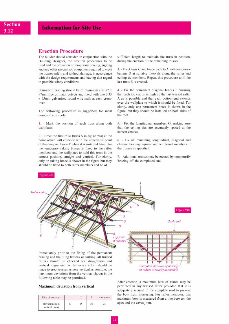
Figure 94a
Figure 94b
Erection ProcedureThe builder should consider, in conjunction with the
Building Designer, the erection procedures to be
used and the provision of temporary bracing, rigging
and any other specialised equipment required to erect
the trusses safely and without damage, in accordance
with the design requirements and having due regard
to possible windy conditions.
Permanent bracing should be of minimum size 22 x
97mm free of major defects and fixed with two 3.35
x 65mm galvanised round wire nails at each cross-
over.
The following procedure is suggested for most
domestic size roofs.
1. - Mark the position of each truss along both
wallplates.
2. - Erect the first truss (truss A in figure 94a) at the
point which will coincide with the uppermost point
of the diagonal brace F when it is installed later. Use
the temporary raking braces B fixed to the rafter
members and the wallplates to hold this truss in the
correct position, straight and vertical. For clarity,
only on raking brace is shown in the figure but they
should be fixed to both rafter members and be of
sufficient length to maintain the truss in position,
during the erection of the remaining trusses.
3. - Erect truss C and brace back to A with temporary
battens D at suitable intervals along the rafter and
ceiling tie members. Repeat this procedure until the
last truss E is erected.
4. - Fix the permanent diagonal braces F ensuring
that each top end is as high up the last trussed rafter
A as is possible and that each bottom-end extends
over the wallplate to which it should be fixed. For
clarity, only one permanent brace is shown in the
figure, but they should be installed on both sides of
the roof.
5. - Fix the longitudinal members G, making sure
that the ceiling ties are accurately spaced at the
correct centres.
6. - Fix all remaining longitudinal, diagonal and
chevron bracing required on the internal members of
the trusses as specified.
7. - Additional trusses may be erected by temporarily
'bracing-off' the completed end.
Gable end
A
B
C
D
EF
G
G
GG
G
Alternative direction of bracing
on rafters is equally acceptable
Lap joint
if required
Gable end
Rise of truss (m) 1 2 3 4 or more
Deviation from 10 15 20 25
vertical (mm)

Information for Site Use
75
Section3.13
(This section is intended to give general guidance toContractors regarding appropriate controls forassessing and documenting the risks associatedwith construction task).Perhaps it is appropriate under this section to note
that the undertaking of Risk Assessments and
compilation of Method Statements (where
appropriate) is the LEGAL DUTY OF ALLCONTRACTORS as it is for Designers under the
Construction (Design and Management) Regulations
1994. Such Assessments are necessary to appraise
hazards and their associated risks in order that these
risks may be either minimised or controlled.
The responsibilities and obligations of Contractors
are primarily laid down in the following Regulations:
Health and Safety at Work Act 1974
Construction (Design and Management) Regulations
1994
Management of Health and Safety at Work
Regulations 1992
Provision and Use of Work Equipment Regulations
1992
Construction (Health, Safety and Welfare)
Regulations 1996 - (CHSW Regulations 1996)
Manual Handling Operations 1992
Workplace (Health, Safety and Welfare) Regulations
1992
Examples of a typical Risk Assessment and
supporting Method Statement are given on pages 76
and 77. These are presented to illustrate the
difference between a Contractors Standard Health
and Safety Policy which should include provision for
all 'Standard' risks - as documented in the
Contractors General Risk Assessment (which may
simply be an amended sheet from the Company
Health and Safety Policy Manual) and PPE/Manual
Handling Risk Assessments and/or detailed Method
Statements which are custom written to deal with
specific, non-standard or particularly risky aspects of
work.
Risk Assessments and Method Statements

Section
3.13Information for Site Use
76
Contractors general risk assessment for theerection and assembly of roof trussesUnder the Management of Health and Safety at Work
Regulations 1992 contractors are required to
undertake and record risk assessments for site
specific tasks and locations of work. These Risk
Assessments can be used to i) identify provision
within tender/contract documents regarding matters
relating to Health and Safety, ii) check Health and
Safety conditions on site, iii) developing safe system
of work and Method Statements where required and
iv) provide information on hazards to
operatives/personnel at the place of work.
By way of an example which illustrates typicalcriteria for assessing the risks associated with aparticular work task the following exampleassessment has been prepared:-
Harm:Significant injuries or fatalities without controls
Persons in Danger:Roof operatives, other operatives in the vicinity,general public as passers by
Controls:This section should typically include informationrelating to the design and use of the following:-Ladders, Scaffolds, Working Platforms, StorageAreas, Edge Protection and Barriers, LiftingEquipment, Disposal of waste, PPE, WarningNotices, Checking Procedures, Adverse weather,Plant Maintenance etc.
PPE:Safety Helmets, Protective Footwear and Glovesshould be worn
Additional Assessments Required? Manual Handling (where appropriate) activitiesand PPE
Method Statement Required?Yes, see method statement ref. MG/GEN/OJ
Can the Work Task be adequatelycontrolled?Yes
Specific Legislation and other InformativeGuidance Documents:CHSW Regs 1996: CDM Regs 1994: ManualHandling Regs 1992 etc
Information, Instruction and Training:See Company Training Information - Nooperatives shall carry out any activity withoutproper training as noted therein
Emergency Procedures:Display Procedure in site offices, Ensure personnelknow how to raise alarm, provide Adequate FirstAid Kit
Monitoring Procedures:This shall be the responsibility of the Site Managerto organise and implement according to establishedprocedure
Any other Items:As appropriate
Signed:
Date:
Project Title: Housing Estate, AnywhereClient: J Bloggs & CoDescription of Works: General Roof Activities
Document Reference No: RA/Gen/OJADate: **/**/**Author: AJF
Hazards: Risk Ratings(This list should also refer to those hazards Without Controls With Controlsidentified in the roof Designers Risk Assessmentand also those contained in the siteHealth and Safety Plan), e.g:Persons falling - High Low
Falling objects - Medium Low
Risk Assessments and Method Statements

Information for Site Use
77
Section3.13
Safe Working Method:For additional reference regarding this method
statement refer to Contractors sketch ref. ***/** as
illustrated on page (?) of this site installation guide.
At all times this method statement assumes that all
appropriate design considerations have been
incorporated and allowed for within the design and
layout of the temporary working platforms.
Additionally, it should be noted that this method
statement refers only to those operations which have
been designated as having a higher level of risk, for
all matters associated with this operation reference
shall be made and working practices adopted which
comply with the Contractors general Risk
Assessment for roof work.
Part 1:1. Construct external perimeter scaffold as per detail
in a manner to ensure sufficient manoeuvring space
around loading platform. Locate vertical truss
restraint standards at position to allow unobstructed
lifting to eaves level working platform. All edge
protection to both the eaves level and the loading
level platforms must be constructed and fixed before
any lifting operations take place. Similarly, erect
internal working platforms at a level (typically)
300mm below ceiling tie level.
Under no circumstances whatsoever shall any edgeprotection be removed to facilitate these operations.2. According to the recommendations of the Manual
Handling Risk Assessment use x No. Personnel to
manually lift individual trusses via the truss restraint
standards to the eaves level working platform. Move
trusses along the length of the roof to their final
position (where they shall immediately be fixed by
carpenters using temporary/permanent bracing - see
part 2 of this method statement). NB. Girder trusses
shall be raised as single component plies and then the
ceiling tie members (min) bolted together according
to the details provided by the truss manufacturer and
in locations marked by him on the trusses; rafter and
web members may be nailed according to further
details provided by the truss manufacturer.
NB. Roof Bracing Details which will include sizesand location of Rafter and Chevron Bracing etc,shall be installed in accordance with the roofdesigners layout drawing.
Part 2:3. When the first truss has been raised and located in
its final position by the truss handling team, the
carpenters shall immediately provide temporary
diagonal restraints at a minimum of three locations to
hold the truss vertical and so as to act as a rigid start
point for the erection of the remainder of the trusses.
This temporary restraint shall preferably be located
outside of the roof structure i.e. Fixed to the external
perimeter scaffold. The positioning of the temporary
braces in this way will then allow unobstructed
passage to the truss handling team as further trusses
are raised and located in their final position.
NB. Wherever possible, Carpenters should use pre-nailed bracing members (accurately marked out tocoincide with the truss centres) to ensure that trusserection progresses smoothly and quickly.4. As soon as sufficient trusses have been temporarily
positioned, the carpenters shall commence the fixing
of internal permanent bracing to create fully stable
sections of roof. Where necessary for carpenters to
work at higher levels than the main internal working
platform then either stepladders or temporary trestles
shall be used between trusses constructed or
positioned on the main platform. Under no
circumstances shall operatives be allowed to climb
within the temporarily braced roof structure.
5. As soon as permanently braced sections of roof
have been completed, it shall be allowed for
operatives to locate working platforms within the
roof structure by positioning suitable boards directly
on top of the ceiling ties. These platforms can then be
used for the installation of services etc. Similarly, at
this time it is appropriate to allow the removal of the
external temporary props in order to allow any gable
masonry construction to be commenced. Gable
construction should not have been allowed to
commence prior to this stage as it is the stability of
the roof construction which provides restraint to the
gable masonry construction.
NB. The dismantling of the internal workingplatform shall only be allowed to commence belowcompleted areas of roof construction as such timewhen no work is being carried out overhead.6. Further areas of roof construction (if appropriate)
shall be carried out according to the identical
principles outlined above.
Task Description: Project Title: Ref:Erection of Trussed Rafter Roof Housing Development at No:Structure using Manual handling Muddy Lane, Date:Method Ref 01. Newtown, Smoke City Author:
Location of Work Task: Project Title:House type A (South Facing only) Erection and Installation of trussed Rafter on Muddy Lane Roof Structure to House Type A
This Safe Working Method Statement has been prepared for the following work.
No other work than that referred to must be carried out.
Risk Assessments and Method Statements

Section
3.14Information for Site Use
78
Construction Check List
Job No: Contractor:
Site: Block:
Inspector: Date:
OK NOT OKYes No
Trussed RaftersCorrect quantity, positions and orientation
Centres not greater than specified
Verticality and bow after erection within code limits
No damage or unauthorised modifications
Girders/Multiple trusses connected together in accordance with specification
Properly seated on wallplates, hangers, etc.
Bracing correct size and in correct position
Bracing connected to each truss as specified
Bracing laps extended over a minimum of 2 trusses
Bracing of truss rafter compression members are installed as specified
Valley set is correctly set out and braced as specified
Valley set is supported on bevelled bottom chord or supported on fillet
Loose TimbersCorrect sizes, position and grade
Centres not greater than specified
Birdsmouth, joints, scarfs etc., accurately and correctly made
Properly seated on wallplates, hangers, etc.
Fixings are to specification
Structural MetalworkTruss clips, framing anchors and other vertical restraints present and fully nailed
Hangers correct to specification and fixed as specified
Gable restraint straps present and correctly fixed including pack between members
Tank PlatformCorrectly positioned and constructed as specified
Loads applied to trusses as allowed for in design
Special ItemsServices in position specified and do not clash with webs
Roof ventilated as specified
Trap hatch formed to specification
Sarking if applicable, is to specification
Tiles fixed are correct weight as specified in design
Comments
✔ ✖

Information for Site Use
79
Section3.15
Nailing and BoltingScab MembersRafter sizes in raised tie trusses often need to be
increased, since the entire weight of the roof
structure is supported on the extended rafters
resulting in large bending forces. Even then, timber
scabs or reinforcing members are often necessary
and it is essential that they are correctly fitted
whenever specified. Scabs may be required on one or
both faces of the extended rafter and may also be
required on multiple trusses. The truss manufacturer
may fix the scabs in the factory prior to delivery or
may provide the scabs loose, with a fixing detail to
allow them to be secured on site. Scabs on multiple
trusses will invariably require bolting - large plate
washers should be used with all bolts.
Typical Scab Nailing PositionsScabs may be fixed by the manufacturer or on site
using a nailing or bolting details provided by the
manufacturer.
Girder TrussesGirder trusses are designed to carry more load than
that from the standard trussed rafter spacing. They
consist of two or more trussed rafters fastened
together. Typically, girder trusses carry other trussed
rafters or infill timbers on shoes attached to the
ceiling tie of the girder.
Girders are fastened together by nails or bolts. When
fastened together on site, bolts must be used for at
least the ceiling tie members, in positions marked by
the truss manufacturer. In all cases, the nails or bolt
must be positioned strictly in accordance with the
manufacturer's instructions.
See TRA Information Sheet 9804 'Girder Trusses
(Principal Trusses) Definitions and Connecting
Together On Site'.
Washers must be used under the head and nut of each
bolt.
Nails and bolts should either be inherently corrosion resistant or protected by a corrosion resistant coating.
Figure 95
Figure 96
Figure 97
Bolt Diameter Washer Size
Diameter Thickness
M8 24mm 2mm
M12 36mm 3mm
M16 48mm 4mm
M20 60mm 5mm
M24 72mm 6mmRafters and webs
nailed
Truss TrussTruss
Nail
group
Nail
group
Nails at
300 ctrs
Nails at
300 ctrs
Ceiling members
bolted togetherBolts spaced to avoid incoming truss fixings
To be effective scabs must be in firm
contact with the wallplate Multiple trusses may also require scabs
These will be invariably bolted into place

Section
3.16Information for Site Use
80
All the trusses (or frames) are generally of two basic
types depending on how they are supported.
Type 1:(Figure 98a) is characterised by a load-bearing
support at or near mid-span and as a result generally
has heavy joists propping relatively light rafters. The
truss may need to be supplied in kit form for
completion on site if it is too high for fabrication or
transportation. The kit form, while requiring some
site fabrication, does make for straightforward
erection as the floor joists can be installed first,
providing a safe, rigid working platform.
Type 2:(Figure 98b) is free spanning between wallplates and
as a result the floor is suspended from the rafters
which consequently are relatively heavy and often as
heavy as the floor joists. The associated kit form is
usually different to that for type 1 in order to
facilitate erection and to ensure that the more
important joints are made under factory controlled
conditions. However, substantial connections, often
employing MiTek field splice plates, fully nailed or
bolts, have to be made between the capping and base
components, handling and erection of these heavy
units needs to be carefully supervised.
Figure 98a
Figure 98b
Figure 98c
Camplated nailed
site connections
Field splice plate,
bolted or nailed
site connections
Cap
Base
Often the cap truss sits in the same plane
as the base truss and they are connected
together using a MiTek Field Splice plate
Field splice plate pressed into one part in
factory and nailed in other part on site
Attic Frames 2 & 3 Part Construction

Information for Site Use
81
Section3.17
Attic Frames - BracingPermanent bracing is required in all roofs for four
reasons:
a. to maintain rafter stabilityb. to prevent dominoeing c. to form diaphragms to transmit wind loads to
shear wallsd. to maintain the stability of internal compression
members
By far the most serious matter which arises in roof
surgeries is rafter (roof) instability, arising from lack
of suitable bracing.
Permanent bracing is the responsibility of the
Building Designer. The advice and recommendations
given here are given in the interests of good building
practice and are not to imply responsibility accepted
by MiTek. They should be considered as the
necessary minimum.
Figure 99a
Figure 99b Figure 99c
Figure 99d
Figure 99e
Note: Bracing shown must be installed
both sides of ridge and repeat at
intervals (with a minimum of two)
along roof. Alternate rising to left and
to right. Where the roof is short the
second line of bracing may cross as
shown by the broken line.
Tight fitting 12mm plywood
fixed with 60mm nails at
250mm centres
50 x 50 ledgers
fixed with 100mm
nails at 250mm
centres
The structural action of diagonal bracing is the completion
of triangulation in various planes, in order to form rigid
diaphragms. For example, in the plane of the rafters this is
provided by rafters, tiling battens and the bracing
members.
The effectiveness of the noggined parts of the diagonals in
figure 99b might be open to question, as it is very
dependent on the quality of installation. Suitable
alternatives are plywood diaphragms (figure 99e).
Diagonals repeat continuously along building, they may
rise to left or right or vary
Two diagonals each end. One diagonal alternatively each
side of centre line elsewhere
25 x 100mm diagonal brace
50 x 50 nogging at plaster boarded
area extended into void areas
Alternative to one line of diagonal rafter bracing
View D
View C
View BView A
View A View B
View D
ViewC
Tiling battens
45º
Insulation
At least 4
trusses per
diagonal
At least 4
trusses per
diagonal
2 No 3.35 x 65mm galvanised
nails at all cross overs
25 x 100mm longitudinal
binders shown thus
25 x 100mm diagonal bracing
shown thus
Solid blocking or herringbone strutting at least at all
bearings and mid span, check NHBC requirements

Section
3.18Information for Site Use
82
Attic Frames - EnvironmentFireRoom-in-the-roof constructions is in an unusual
position in regard to fire regulations. The floor, of
course, must have the usual, minimum modified half-
hour endurance. However, additional precautions
should be taken to prevent spread-of-fire into the
roof cavities and to ensure the integrity of the
connectors for the full half hour.
Alternative solutions are:
a. Continue the floor boarding into the side triangles
sealing it to the wall plate as shown (figure 100a) and
protect the connectors with 12.7mm plasterboard
cover plates.
b. Install under the floor joists a ceiling lining
capable of providing full or almost full protection eg:
1.12.7mm 'Fireline' plasterboard2.Normal 12.7mm plasterboard plus a 5mm plasterskim coat3.12.7mm plus 9.5mm plasterboard with staggeredjointsIf compliance with the ventilation requirements of
the Building Regulations is to be effected through
eaves vents, these should be made impassable to fire.
Insulation and VentilationThought should be given to the type and location at
an early stage, as this might well determine the depth
of rafter to be adopted.
A cool regime (figure 100b) required ventilation to
control condensation. An airgap of not less than
50mm should be provided between the top of the
insulation and the underside of the roof covering.
With a 100mm mineral wool quilt the smallest
standard finished size of timber to provide the
necessary depth is 147mm.
Warm roof regimes (figure 100c) need the same
ventilation with, in addition, ridge vents providing at
least a 5mm minimum continuous gap.
Figure 100a
Figure 100c
Figure 100b
Floor boarding
Seal/blocking
50mm ventilation
gap
Vents equivalent to 25mm
minimum continuous gap
Vents to equivalent to 5mm
minimum continuous gap at
ridge
Vents equivalent to
25mm minimum
continuous gap
Insulation
Insulation
Vapour barrier
Vapour barrier
Plasterboard cover
plate
Connector

Information for Site Use
83
Section3.19
General Construction detailsIn general, it is preferable to use one of the
proprietary types of fixings, 'A', between the ends of
the trussed rafters and the wall plates or bearings as
shown in figure 103.
Where proprietary fixings are not used, the minimum
fixing at each bearing position should consist of two
4.5 x 100mm long galvanised round wire nails,
which are skew nailed from each side of the trussed
rafter into the wallplate or bearing. Where nailing
through the punched metal plate cannot be avoided,
the nails should be driven through the holes in the
fasteners. This method of fixing should not be used
with stainless steel metal plate fasteners or where the
workmanship on site is not of a sufficiently high
standard to ensure that the fasteners, joints, timber
members and bearings will not be damaged by
careless positioning or overdriving of nails.
Internal non-loadbearing wallsIt is advisable to erect non-loadbearing walls after
the tiling has been completed thus allowing
deflection to take place under the dead load, thereby
reducing the risk f cracking appearing in the ceiling
finishes. If partitions are of brick or block, then as an
alternative the final course may be omitted until
tiling has been completed
Figure 102
Figure 105
Figure 101
Figure 103
Figure 104
The Building Designer should ensure that, when required,
adequate holding down fixings, 'C', are specified for both
the trussed rafter and the wall plates or bearings.Restraint strap at ceiling level
Restraint strap at rafter level
Noggings to be
provided and set
horizontal unless
the strap has a
twist to line it up
with the roof
slope
Strap bedded under
a cut block
Truss clip
Partition
Omit final course
until tiling is
completedPacking piece between
inner leaf and first rafter
Strap fixed to solid noggings with a
minimum of four fixings of which at least
one is to be in the third joist/rafter or in
a noggin beyond the third joist/rafter
A
C

Section
3.19Information for Site Use
84
General Construction detailsHogging over party wallsParty walls should be stopped 25mm below the tops
of rafters. During construction layers of non-
combustible compressible fill such as 50mm mineral
wool should be pressed onto the locations shown to
provide a fire stop as figure 106.
Continuity across party wallsIf the tiling battens are required to be discontinued
over a party wall, then lateral restraint must be
provided in addition to that required to transfer
longitudinal bracing forces.
This should consist of straps adequately protected
against corrosion. These straps should be spaced at
not more than 1.5m centres and be fixed to two rafter
members and noggins on each side of the party wall
by 3.35mm diameter nails with a minimum
penetration into the timber of 32mm.
HipboardsFixing over flat-top girder
Where hipboards pass over and are supported on flat
top girder trusses, the hipboard must be notched in
order to achieve the correct height for the hipboard
and to provide horizontal bearing. The flying rafter
of the truss may need to be trimmed but in no
circumstances should the flat chord or the rafter
below the joint be cut. In most cases the hipboard is
supplied in two parts which can be joined over the
flat top truss. One method of providing the necessary
fixing is illustrated in figure 108.
Hipboard to be notched over girder truss and butted
together over centre of girder.
Figure 109
Figure 106
Figure 107
Figure 108
50 x 150 ledger nailed
to truss using 3.75 x
90mm galvanised
round wire nails
Hipboards
X
X
X
25mm
XFill
Tiles
Felt
Trussed rafter
Fill between battens
Tiling battens
Tiling batten
Compressible fill
Top of wall
Underside of rafter
Hand nail plate
2 No per connection
Use 3.75 x 30mm
square twisted
sheradised nails 2 ply (typical)
hip girder truss
Hipboard to be
notched over
ledger
Lower hipboard
Y/4
(max)
Section X - X
Y
Batten
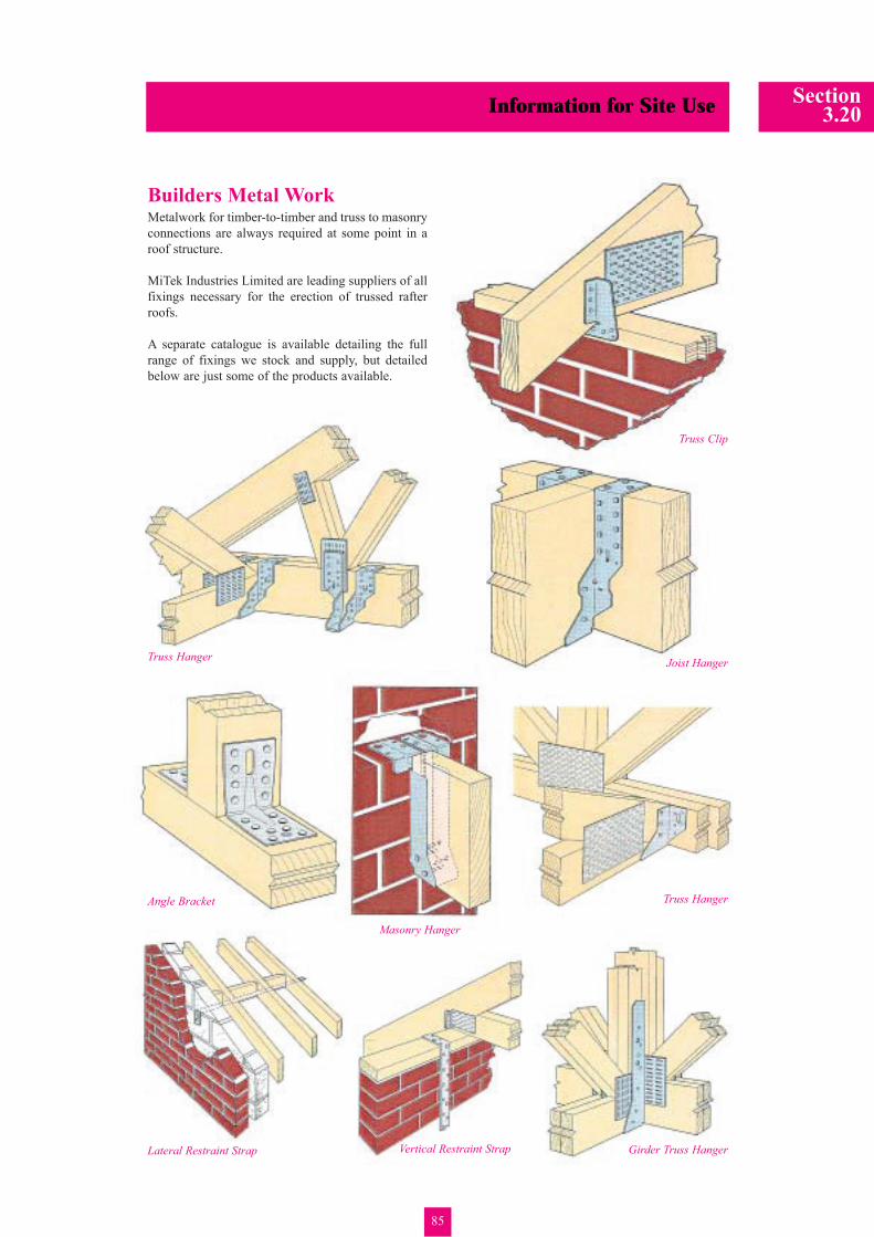
Information for Site Use
85
Section3.20
Builders Metal WorkMetalwork for timber-to-timber and truss to masonry
connections are always required at some point in a
roof structure.
MiTek Industries Limited are leading suppliers of all
fixings necessary for the erection of trussed rafter
roofs.
A separate catalogue is available detailing the full
range of fixings we stock and supply, but detailed
below are just some of the products available.
Truss Hanger
Angle Bracket
Masonry Hanger
Vertical Restraint StrapLateral Restraint Strap
Truss Clip
Joist Hanger
Truss Hanger
Girder Truss Hanger