information and coding theory -...
TRANSCRIPT

OTE/SPH OTE/SPHJWBK102-01 JWBK102-Farrell June 17, 2006 17:55 Char Count= 0
1Information and Coding Theory
In his classic paper ‘A Mathematical Theory of Communication’, Claude Shannon [1] intro-duced the main concepts and theorems of what is known as information theory. Definitionsand models for two important elements are presented in this theory. These elements are thebinary source (BS) and the binary symmetric channel (BSC). A binary source is a device thatgenerates one of the two possible symbols ‘0’ and ‘1’ at a given rate r, measured in symbolsper second. These symbols are called bits (binary digits) and are generated randomly.
The BSC is a medium through which it is possible to transmit one symbol per time unit.However, this channel is not reliable, and is characterized by the error probability p (0 ≤ p ≤1/2) that an output bit can be different from the corresponding input. The symmetry of thischannel comes from the fact that the error probability p is the same for both of the symbolsinvolved.
Information theory attempts to analyse communication between a transmitter and a receiverthrough an unreliable channel, and in this approach performs, on the one hand, an analysis ofinformation sources, especially the amount of information produced by a given source, and, onthe other hand, states the conditions for performing reliable transmission through an unreliablechannel.
There are three main concepts in this theory:
1. The first one is the definition of a quantity that can be a valid measurement of information,which should be consistent with a physical understanding of its properties.
2. The second concept deals with the relationship between the information and the source thatgenerates it. This concept will be referred to as source information. Well-known informationtheory techniques like compression and encryption are related to this concept.
3. The third concept deals with the relationship between the information and the unreliablechannel through which it is going to be transmitted. This concept leads to the definition ofa very important parameter called the channel capacity. A well-known information theorytechnique called error-correction coding is closely related to this concept. This type ofcoding forms the main subject of this book.
One of the most used techniques in information theory is a procedure called coding, which isintended to optimize transmission and to make efficient use of the capacity of a given channel.
Essentials of Error-Control Coding Jorge Castineira Moreira and Patrick Guy FarrellC© 2006 John Wiley & Sons, Ltd
1
COPYRIG
HTED M
ATERIAL
OTE/SPH OTE/SPHJWBK102-01 JWBK102-Farrell June 17, 2006 17:55 Char Count= 0
2 Essentials of Error-Control Coding
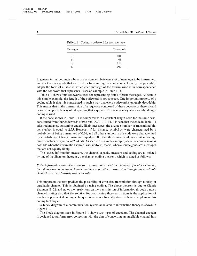
Table 1.1 Coding: a codeword for each message
Messages Codewords
s1 101
s2 01
s3 110
s4 000
In general terms, coding is a bijective assignment between a set of messages to be transmitted,and a set of codewords that are used for transmitting these messages. Usually this procedureadopts the form of a table in which each message of the transmission is in correspondencewith the codeword that represents it (see an example in Table 1.1).
Table 1.1 shows four codewords used for representing four different messages. As seen inthis simple example, the length of the codeword is not constant. One important property of acoding table is that it is constructed in such a way that every codeword is uniquely decodable.This means that in the transmission of a sequence composed of these codewords there shouldbe only one possible way of interpreting that sequence. This is necessary when variable-lengthcoding is used.
If the code shown in Table 1.1 is compared with a constant-length code for the same case,constituted from four codewords of two bits, 00, 01, 10, 11, it is seen that the code in Table 1.1adds redundancy. Assuming equally likely messages, the average number of transmitted bitsper symbol is equal to 2.75. However, if for instance symbol s2 were characterized by aprobability of being transmitted of 0.76, and all other symbols in this code were characterizedby a probability of being transmitted equal to 0.08, then this source would transmit an averagenumber of bits per symbol of 2.24 bits. As seen in this simple example, a level of compression ispossible when the information source is not uniform, that is, when a source generates messagesthat are not equally likely.
The source information measure, the channel capacity measure and coding are all relatedby one of the Shannon theorems, the channel coding theorem, which is stated as follows:
If the information rate of a given source does not exceed the capacity of a given channel,then there exists a coding technique that makes possible transmission through this unreliablechannel with an arbitrarily low error rate.
This important theorem predicts the possibility of error-free transmission through a noisy orunreliable channel. This is obtained by using coding. The above theorem is due to ClaudeShannon [1, 2], and states the restrictions on the transmission of information through a noisychannel, stating also that the solution for overcoming those restrictions is the application ofa rather sophisticated coding technique. What is not formally stated is how to implement thiscoding technique.
A block diagram of a communication system as related to information theory is shown inFigure 1.1.
The block diagram seen in Figure 1.1 shows two types of encoders. The channel encoderis designed to perform error correction with the aim of converting an unreliable channel into

OTE/SPH OTE/SPHJWBK102-01 JWBK102-Farrell June 17, 2006 17:55 Char Count= 0
Information and Coding Theory 3
Sourceencoder
Noisy channel
Sourcedecoder
Channeldecoder
Destination
Source Channelencoder
Figure 1.1 A communication system: source and channel coding
a reliable one. On the other hand, there also exists a source encoder that is designed to makethe source information rate approach the channel capacity. The destination is also called theinformation sink.
Some concepts relating to the transmission of discrete information are introduced in thefollowing sections.
1.1 Information
1.1.1 A Measure of Information
From the point of view of information theory, information is not knowledge, as commonlyunderstood, but instead relates to the probabilities of the symbols used to send messagesbetween a source and a destination over an unreliable channel. A quantitative measure ofsymbol information is related to its probability of occurrence, either as it emerges from asource or when it arrives at its destination. The less likely the event of a symbol occurrence,the higher is the information provided by this event. This suggests that a quantitative measureof symbol information will be inversely proportional to the probability of occurrence.
Assuming an arbitrary message xi which is one of the possible messages from a set a givendiscrete source can emit, and P(xi ) = Pi is the probability that this message is emitted, theoutput of this information source can be modelled as a random variable X that can adopt any ofthe possible values xi , so that P(X = xi ) = Pi . Shannon defined a measure of the informationfor the event xi by using a logarithmic measure operating over the base b:
Ii ≡ − logb Pi = logb
(1
Pi
)(1)
The information of the event depends only on its probability of occurrence, and is notdependent on its content.
OTE/SPH OTE/SPHJWBK102-01 JWBK102-Farrell June 17, 2006 17:55 Char Count= 0
4 Essentials of Error-Control Coding
The base of the logarithmic measure can be converted by using
loga(x) = logb(x)1
logb(a)(2)
If this measure is calculated to base 2, the information is said to be measured in bits. If themeasure is calculated using natural logarithms, the information is said to be measured in nats.As an example, if the event is characterized by a probability of Pi = 1/2, the correspondinginformation is Ii = 1 bit. From this point of view, a bit is the amount of information obtainedfrom one of two possible, and equally likely, events. This use of the term bit is essentiallydifferent from what has been described as the binary digit. In this sense the bit acts as the unitof the measure of information.
Some properties of information are derived from its definition:
Ii ≥ 0 0 ≤ Pi ≤ 1
Ii → 0 if Pi → 1
Ii > I j if Pi < Pj
For any two independent source messages xi and x j with probabilities Pi and Pj respectively,and with joint probability P(xi , x j ) = Pi Pj , the information of the two messages is the additionof the information in each message:
Ii j = logb1
Pi Pj= logb
1
Pi+ logb
1
Pj= Ii + I j
1.2 Entropy and Information Rate
In general, an information source generates any of a set of M different symbols, which areconsidered as representatives of a discrete random variable X that adopts any value in the rangeA = {x1, x2, . . . , xM}. Each symbol xi has the probability Pi of being emitted and containsinformation Ii . The symbol probabilities must be in agreement with the fact that at least oneof them will be emitted, so
M∑i=1
Pi = 1 (3)
The source symbol probability distribution is stationary, and the symbols are independentand transmitted at a rate of r symbols per second. This description corresponds to a discretememoryless source (DMS), as shown in Figure 1.2.
Each symbol contains the information Ii so that the set {I1, I2, . . . , IM} can be seen as adiscrete random variable with average information
Hb(X ) =M∑
i=1
Pi Ii =M∑
i=1
Pi logb
(1
Pi
)(4)

OTE/SPH OTE/SPHJWBK102-01 JWBK102-Farrell June 17, 2006 17:55 Char Count= 0
Information and Coding Theory 5
Discretememorylesssource
xi , x j , ...
Figure 1.2 A discrete memoryless source
The function so defined is called the entropy of the source. When base 2 is used, the entropyis measured in bits per symbol:
H (X ) =M∑
i=1
Pi Ii =M∑
i=1
Pi log2
(1
Pi
)bits per symbol (5)
The symbol information value when Pi = 0 is mathematically undefined. To solve thissituation, the following condition is imposed: Ii = ∞ if Pi = 0. Therefore Pi log2
(1/
Pi) = 0
(L’Hopital’s rule) if Pi = 0. On the other hand, Pi log(1/
Pi) = 0 if Pi = 1.
Example 1.1: Suppose that a DMS is defined over the range of X, A = {x1, x2, x3, x4}, andthe corresponding probability values for each symbol are P(X = x1) = 1/2, P(X = x2) =P(X = x3) = 1/8 and P(X = x4) = 1/4.
Entropy for this DMS is evaluated as
H (X ) =M∑
i=1
Pi log2
(1
Pi
)= 1
2log2(2) + 1
8log2(8) + 1
8log2(8) + 1
4log2(4)
= 1.75 bits per symbol
Example 1.2: A source characterized in the frequency domain with a bandwidth of W =4000 Hz is sampled at the Nyquist rate, generating a sequence of values taken from the rangeA = {−2, −1, 0, 1, 2} with the following corresponding set of probabilities
{12, 1
4, 1
8, 1
16, 1
16
}.
Calculate the source rate in bits per second.Entropy is first evaluated as
H (X ) =M∑
i=1
Pi log2
(1
Pi
)= 1
2log2(2) + 1
4log2(4) + 1
8log2(8)
+2 × 1
16log2(16) = 15
8bits per sample
The minimum sampling frequency is equal to 8000 samples per second, so that the informationrate is equal to 15 kbps.
Entropy can be evaluated to a different base by using
Hb(X ) = H (X )
log2(b)(6)

OTE/SPH OTE/SPHJWBK102-01 JWBK102-Farrell June 17, 2006 17:55 Char Count= 0
6 Essentials of Error-Control Coding
Entropy H (X ) can be understood as the mean value of the information per symbol providedby the source being measured, or, equivalently, as the mean value experienced by an observerbefore knowing the source output. In another sense, entropy is a measure of the randomnessof the source being analysed. The entropy function provides an adequate quantitative measureof the parameters of a given source and is in agreement with physical understanding of theinformation emitted by a source.
Another interpretation of the entropy function [5] is seen by assuming that if n � 1 symbolsare emitted, nH (X ) bits is the total amount of information emitted. As the source generatesr symbols per second, the whole emitted sequence takes n/r seconds. Thus, information willbe transmitted at a rate of
nH (X )
(n/r )bps (7)
The information rate is then equal to
R = r H (X ) bps (8)
The Shannon theorem states that information provided by a given DMS can be coded usingbinary digits and transmitted over an equivalent noise-free channel at a rate of
rb ≥ R symbols or binary digits per second
It is again noted here that the bit is the unit of information, whereas the symbol or binarydigit is one of the two possible symbols or signals ‘0’ or ‘1’, usually also called bits.
Theorem 1.1: Let X be a random variable that adopts values in the range A = {x1 ,x2, . . . , xM} and represents the output of a given source. Then it is possible to show that
0 ≤ H (X ) ≤ log2(M) (9)
Additionally,
H (X ) = 0 if and only if Pi = 1 for some i
H (X ) = log2(M) if and only if Pi = 1/
M for every i (10)
The condition 0 ≤ H (X ) can be verified by applying the following:
Pi log2(1/Pi ) → 0 if Pi → 0
The condition H (X ) ≤ log2(M) can be verified in the following manner:Let Q1, Q2, . . . , QM be arbitrary probability values that are used to replace terms 1/Pi by
the terms Qi/Pi in the expression of the entropy [equation (5)]. Then the following inequalityis used:
ln(x) ≤ x − 1
where equality occurs if x = 1 (see Figure 1.3).

OTE/SPH OTE/SPHJWBK102-01 JWBK102-Farrell June 17, 2006 17:55 Char Count= 0
Information and Coding Theory 7
0.2 0.4 0.6 0.8 1 1.2 1.4 1.6 1.8 2–2
–1.5
–1
–0.5
0
0.5
1
x
y1,y2
y2=ln(x)
y1=x–1
Figure 1.3 Inequality ln(x) ≤ x − 1
After converting entropy to its natural logarithmic form, we obtain
M∑i=1
Pi log2
(Qi
Pi
)= 1
ln(2)
M∑i=1
Pi ln
(Qi
Pi
)and if x = Qi
/Pi ,
M∑i=1
Pi ln
(Qi
Pi
)≤
M∑i=1
Pi
(Qi
Pi− 1
)=
M∑i=1
Qi −M∑
i=1
Pi (11)
As the coefficients Qi are probability values, they fit the normalizing condition∑M
i=1 Qi ≤ 1,
and it is also true that∑M
i=1 Pi = 1.Then
M∑i=1
Pi log2
(Qi
Pi
)≤ 0 (12)
If now the probabilities Qi adopt equally likely values Qi = 1/
M,
M∑i=1
Pi log2
(1
Pi M
)=
M∑i=1
Pi log2
(1
Pi
)−
M∑i=1
Pi log2(M) = H (X ) − log2(M) ≤ 0
H (X ) ≤ log2(M) (13)

OTE/SPH OTE/SPHJWBK102-01 JWBK102-Farrell June 17, 2006 17:55 Char Count= 0
8 Essentials of Error-Control Coding
0 0.1 0.2 0.3 0.4 0.5 0.6 0.7 0.8 0.9 10
0.1
0.2
0.3
0.4
0.5
0.6
0.7
0.8
0.9
1
α
H(X)
Figure 1.4 Entropy function for the binary source
In the above inequality, equality occurs when log2
(1/
Pi) = log2(M), which means that Pi =
1/
M .The maximum value of the entropy is then log2(M), and occurs when all the symbols
transmitted by a given source are equally likely. Uniform distribution corresponds to maximumentropy.
In the case of a binary source (M = 2) and assuming that the probabilities of the symbolsare the values
P0 = α P1 = 1 − α (14)
the entropy is equal to
H (X ) = �(α) = α log2
(1
α
)+ (1 − α) log2
(1
1 − α
)(15)
This expression is depicted in Figure 1.4.The maximum value of this function is given when α = 1 − α, that is, α = 1/2, so that the
entropy is equal to H (X ) = log2 2 = 1 bps. (This is the same as saying one bit per binary digitor binary symbol.)
When α → 1, entropy tends to zero. The function �(α) will be used to represent the entropyof the binary source, evaluated using logarithms to base 2.
Example 1.3: A given source emits r = 3000 symbols per second from a range of foursymbols, with the probabilities given in Table 1.2.

OTE/SPH OTE/SPHJWBK102-01 JWBK102-Farrell June 17, 2006 17:55 Char Count= 0
Information and Coding Theory 9
Table 1.2 Example 1.3
xi Pi Ii
A 1/3 1.5849
B 1/3 1.5849
C 1/6 2.5849
D 1/6 2.5849
The entropy is evaluated as
H (X ) = 2 × 1
3× log2(3) + 2 × 1
6× log2(6) = 1.9183 bits per symbol
And this value is close to the maximum possible value, which is log2(4) = 2 bits per symbol.The information rate is equal to
R = r H (X ) = (3000)1.9183 = 5754.9 bps
1.3 Extended DMSs
In certain circumstances it is useful to consider information as grouped into blocks of symbols.This is generally done in binary format. For a memoryless source that takes values in therange {x1, x2, . . . , xM}, and where Pi is the probability that the symbol xi is emitted, the ordern extension of the range of a source has Mn symbols {y1, y2, . . . , yMn}. The symbol yi isconstituted from a sequence of n symbols xi j . The probability P(Y = yi ) is the probability ofthe corresponding sequence xi1, xi2, . . . , xin:
P(Y = yi ) = Pi1, Pi2, . . . , Pin (16)
where yi is the symbol of the extended source that corresponds to the sequence xi1, xi2, . . . , xin.Then
H (Xn) =∑y=xn
P(yi ) log2
1
P(yi )(17)
Example 1.4: Construct the order 2 extension of the source of Example 1.1, and calculate itsentropy.
Symbols of the original source are characterized by the probabilities P(X = x1) =1/2, P(X = x2) = P(X = x3) = 1/8 and P(X = x4) = 1/4.
Symbol probabilities for the desired order 2 extended source are given in Table 1.3.The entropy of this extended source is equal to
H (X2) =M2∑i=1
Pi log2
(1
Pi
)= 0.25 log2(4) + 2 × 0.125 log2(8) + 5 × 0.0625 log2(16)
+4 × 0.03125 log2(32) + 4 × 0.015625 log2(64) = 3.5 bits per symbol

OTE/SPH OTE/SPHJWBK102-01 JWBK102-Farrell June 17, 2006 17:55 Char Count= 0
10 Essentials of Error-Control Coding
Table 1.3 Symbols of the order 2 extended source and their probabilities for Example 1.4
Symbol Probability Symbol Probability Symbol Probability Symbol Probability
x1x1 0.25 x2x1 0.0625 x3x1 0.0625 x4x1 0.125
x1x2 0.0625 x2x2 0.015625 x3x2 0.015625 x4x2 0.03125
x1x3 0.0625 x2x3 0.015625 x3x3 0.015625 x4x3 0.03125
x1x4 0.125 x2x4 0.03125 x3x4 0.03125 x4x4 0.0625
As seen in this example, the order 2 extended source has an entropy which is twice that of theentropy of the original, non-extended source. It can be shown that the order n extension of aDMS fits the condition H (Xn) = nH (X ).
1.4 Channels and Mutual Information
1.4.1 Information Transmission over Discrete Channels
A quantitative measure of source information has been introduced in the above sections. Nowthe transmission of that information through a given channel will be considered. This willprovide a quantitative measure of the information received after its transmission through thatchannel. Here attention is on the transmission of the information, rather than on its generation.
A channel is always a medium through which the information being transmitted can sufferfrom the effect of noise, which produces errors, that is, changes of the values initially transmit-ted. In this sense there will be a probability that a given transmitted symbol is converted intoanother symbol. From this point of view the channel is considered as unreliable. The Shannonchannel coding theorem gives the conditions for achieving reliable transmission through anunreliable channel, as stated previously.
1.4.2 Information Channels
Definition 1.1: An information channel is characterized by an input range of symbols{x1, x2, . . . , xU }, an output range {y1, y2, . . . , yV } and a set of conditional probabilitiesP(y j/xi ) that determines the relationship between the input xi and the output y j . This con-ditional probability corresponds to that of receiving symbol y j if symbol xi was previouslytransmitted, as shown in Figure 1.5.
The set of probabilities P(y j/xi ) is arranged into a matrix Pch that characterizes completelythe corresponding discrete channel:
Pi j = P(y j/xi )

OTE/SPH OTE/SPHJWBK102-01 JWBK102-Farrell June 17, 2006 17:55 Char Count= 0
Information and Coding Theory 11
x1
y1
y2
y3
x2
P (y3 / x2)
P (y1 / x1)
P (y1 / x2)
P (y2 / x1)
P (y2 / x2)
P (y3 / x1)
Figure 1.5 A discrete transmission channel
Pch =
⎡⎢⎢⎢⎢⎣P(y1/x1) P(y2/x1) · · · P(yV /x1)
P(y1/x2) P(y2/x2) · · · P(yV /x2)
......
...
P(y1/xU ) P(y2/xU ) · · · P(yV /xU )
⎤⎥⎥⎥⎥⎦ (18)
Pch =
⎡⎢⎢⎢⎢⎣P11 P12 · · · P1V
P21 P22 · · · P2V
......
...
PU1 PU2 · · · PU V
⎤⎥⎥⎥⎥⎦ (19)
Each row in this matrix corresponds to an input, and each column corresponds to an output.Addition of all the values of a row is equal to one. This is because after transmitting a symbolxi , there must be a received symbol y j at the channel output.
Therefore,
V∑j=1
Pi j = 1, i = 1, 2, . . . , U (20)
Example 1.5: The binary symmetric channel (BSC).The BSC is characterized by a probability p that one of the binary symbols converts into the
other one (see Figure 1.6). Each binary symbol has, on the other hand, a probability of beingtransmitted. The probabilities of a 0 or a 1 being transmitted are α and 1 − α respectively.
According to the notation used,
x1 = 0, x2 = 1 and y1 = 0, y2 = 1

OTE/SPH OTE/SPHJWBK102-01 JWBK102-Farrell June 17, 2006 17:55 Char Count= 0
12 Essentials of Error-Control Coding
0
p
p
1
0
1
1 – p
1 – p
P(0) = α
P(1) = 1– α
Figure 1.6 Binary symmetric channel
The probability matrix for the BSC is equal to
Pch =[
1 − p pp 1 − p
](21)
Example 1.6: The binary erasure channel (BEC).In its most basic form, the transmission of binary information involves sending two different
waveforms to identify the symbols ‘0’ and ‘1’. At the receiver, normally an optimum detectionoperation is used to decide whether the waveform received, affected by filtering and noise inthe channel, corresponds to a ‘0’ or a ‘1’. This operation, often called matched filter detection,can sometimes give an indecisive result. If confidence in the received symbol is not high, itmay be preferable to indicate a doubtful result by means of an erasure symbol. Correction ofthe erasure symbols is then normally carried out by other means in another part of the system.
In other scenarios the transmitted information is coded, which makes it possible to detect ifthere are errors in a bit or packet of information. In these cases it is also possible to apply theconcept of data erasures. This is used, for example, in the concatenated coding system of thecompact disc, where on receipt of the information the first decoder detects errors and marksor erases a group of symbols, thus enabling the correction of these symbols in the seconddecoder. Another example of the erasure channel arises during the transmission of packetsover the Internet. If errors are detected in a received packet, then they can be erased, andthe erasures corrected by means of retransmission protocols (normally involving the use of aparallel feedback channel).
The use of erasures modifies the BSC model, giving rise to the BEC, as shown in Figure 1.7.For this channel, 0 ≤ p ≤ 1 / 2, where p is the erasure probability, and the channel model has
two inputs and three outputs. When the received values are unreliable, or if blocks are detected
p
p0
1
0
11− p
1− p
?
P (0) = α
P (1) = 1− α
x1
x2
y1
y2
y3
Figure 1.7 Binary erasure channel

OTE/SPH OTE/SPHJWBK102-01 JWBK102-Farrell June 17, 2006 17:55 Char Count= 0
Information and Coding Theory 13
to contain errors, then erasures are declared, indicated by the symbol ‘?’. The probabilitymatrix of the BEC is the following:
Pch =[
1 − p p 00 p 1 − p
](22)
1.5 Channel Probability Relationships
As stated above, the probability matrix Pch characterizes a channel. This matrix is of orderU × V for a channel with U input symbols and V output symbols. Input symbols are char-acterized by the set of probabilities {P(x1), P(x2), . . . , P(xU )}, whereas output symbols arecharacterized by the set of probabilities {P(y1), P(y2), . . . , P(yV )}.
Pch =
⎡⎢⎢⎢⎣P11 P12 · · · P1V
P21 P22 · · · P2V...
......
PU1 PU2 PU V
⎤⎥⎥⎥⎦The relationships between input and output probabilities are the following: The symbol y1
can be received in U different ways. In fact this symbol can be received with probability P11 ifsymbol x1 was actually transmitted, with probability P21 if symbol x2 was actually transmitted,and so on.
Any of the U input symbols can be converted by the channel into the output symbol y1.The probability of the reception of symbol y1, P(y1), is calculated as P(y1) = P11 P(x1) +P21 P(x2) + · · · + PU1 P(xU ). Calculation of the probabilities of the output symbols leads tothe following system of equations:
P11 P(x1) + P21 P(x2) + · · · + PU1 P(xU ) = P(y1)P12 P(x1) + P22 P(x2) + · · · + PU2 P(xU ) = P(y2)
...
P1V P(x1) + P2V P(x2) + · · · + PU V P(xU ) = P(yV )
(23)
Output symbol probabilities are calculated as a function of the input symbol probabilitiesP(xi ) and the conditional probabilities P(y j/xi ). It is however to be noted that knowledge ofthe output probabilities P(y j ) and the conditional probabilities P(y j/xi ) provides solutionsfor values of P(xi ) that are not unique. This is because there are many input probabilitydistributions that give the same output distribution.
Application of the Bayes rule to the conditional probabilities P(y j/xi ) allows us to determinethe conditional probability of a given input xi after receiving a given output y j :
P(xi/y j ) = P(y j/xi )P(xi )
P(y j )(24)

OTE/SPH OTE/SPHJWBK102-01 JWBK102-Farrell June 17, 2006 17:55 Char Count= 0
14 Essentials of Error-Control Coding
1/4
1
0
7/8
1/8
3/40
1
X Y
P (0) = 4/5
P (1) = 1/5
Figure 1.8 Example 1.7
By combining this expression with expression (23), equation (24) can be written as
P(xi/y j ) = P(y j/xi )P(xi )∑Ui=1 P(y j/xi )P(xi )
(25)
Conditional probabilities P(y j/xi ) are usually called forward probabilities, and conditionalprobabilities P(xi/y j ) are known as backward probabilities. The numerator in the above ex-pression describes the probability of the joint event:
P(xi , y j ) = P(y j/xi )P(xi ) = P(xi/y j )P(y j ) (26)
Example 1.7: Consider the binary channel for which the input range and output range are inboth cases equal to {0, 1}. The corresponding transition probability matrix is in this case equal to
Pch =[
3/4 1/41/8 7/8
]Figure 1.8 represents this binary channel.
Source probabilities provide the statistical information about the input symbols. In this caseit happens that P(X = 0) = 4/5 and P(X = 1) = 1/5. According to the transition probabilitymatrix for this case,
P(Y = 0/X = 0) = 3/4 P(Y = 1/X = 0) = 1/4P(Y = 0/X = 1) = 1/8 P(Y = 1/X = 1) = 7/8
These values can be used to calculate the output symbol probabilities:
P(Y = 0) = P(Y = 0/X = 0)P(X = 0) + P(Y = 0/X = 1)P(X = 1)
= 3
4× 4
5+ 1
8× 1
5= 25
40
P(Y = 1) = P(Y = 1/X = 0)P(X = 0) + P(Y = 1/X = 1)P(X = 1)
= 1
4× 4
5+ 7
8× 1
5= 15
40
which confirms that P(Y = 0) + P(Y = 1) = 1 is true.

OTE/SPH OTE/SPHJWBK102-01 JWBK102-Farrell June 17, 2006 17:55 Char Count= 0
Information and Coding Theory 15
These values can be used to evaluate the backward conditional probabilities:
P(X = 0/Y = 0) = P(Y = 0/X = 0)P(X = 0)
P(Y = 0)= (3/4)(4/5)
(25/40)= 24
25
P(X = 0/Y = 1) = P(Y = 1/X = 0)P(X = 0)
P(Y = 1)= (1/4)(4/5)
(15/40)= 8
15
P(X = 1/Y = 1) = P(Y = 1/X = 1)P(X = 1)
P(Y = 1)= (7/8)(1/5)
(15/40)= 7
15
P(X = 1/Y = 0) = P(Y = 0/X = 1)P(X = 1)
P(Y = 0)= (1/8)(1/5)
(25/40)= 1
25
1.6 The A Priori and A Posteriori Entropies
The probability of occurrence of a given output symbol y j is P(y j ), calculated using expression(23). However, if the actual transmitted symbol xi is known, then the related conditionalprobability of the output symbol becomes P(y j/xi ). In the same way, the probability of agiven input symbol, initially P(xi ), can also be refined if the actual output is known. Thus,if the received symbol y j appears at the output of the channel, then the related input symbolconditional probability becomes P(xi/y j ).
The probability P(xi ) is known as the a priori probability; that is, it is the probability thatcharacterizes the input symbol before the presence of any output symbol is known. Normally,this probability is equal to the probability that the input symbol has of being emitted by thesource (the source symbol probability). The probability P(xi/y j ) is an estimate of the symbolxi after knowing that a given symbol y j appeared at the channel output, and is called the aposteriori probability.
As has been defined, the source entropy is an average calculated over the information of aset of symbols for a given source:
H (X ) =∑
i
P(xi ) log2
[1
P(xi )
]
This definition corresponds to the a priori entropy. The a posteriori entropy is given by thefollowing expression:
H (X/y j ) =∑
i
P(xi/y j ) log2
[1
P(xi/y j )
]i = 1, 2, . . . , U (27)
Example 1.8: Determine the a priori and a posteriori entropies for the channel ofExample 1.7.
The a priori entropy is equal to
H (X ) = 4
5log2
(5
4
)+ 1
5log2(5) = 0.7219 bits

OTE/SPH OTE/SPHJWBK102-01 JWBK102-Farrell June 17, 2006 17:55 Char Count= 0
16 Essentials of Error-Control Coding
Assuming that a ‘0’ is present at the channel output,
H (X/0) = 24
25log2
(25
24
)+ 1
25log2 (25) = 0.2423 bits
and in the case of a ‘1’ present at the channel output,
H (X/1) = 8
15log2
(15
8
)+ 7
15log2
(15
7
)= 0.9968 bits
Thus, entropy decreases after receiving a ‘0’ and increases after receiving a ‘1’.
1.7 Mutual Information
According to the description of a channel depicted in Figure 1.5, P(xi ) is the probability thata given input symbol is emitted by the source, P(y j ) determines the probability that a givenoutput symbol y j is present at the channel output, P(xi , y j ) is the joint probability of havingsymbol xi at the input and symbol y j at the output, P(y j/xi ) is the probability that the channelconverts the input symbol xi into the output symbol y j and P(xi/y j ) is the probability that xi
has been transmitted if y j is received.
1.7.1 Mutual Information: Definition
Mutual information measures the information transferred when xi is sent and y j is received,and is defined as
I (xi , y j ) = log2
P(xi/y j )
P(xi )bits (28)
In a noise-free channel, each y j is uniquely connected to the corresponding xi , and so theyconstitute an input–output pair (xi , y j ) for which P(xi/y j ) = 1 and I (xi , y j ) = log2
1P(xi )
bits;that is, the transferred information is equal to the self-information that corresponds to the inputxi .
In a very noisy channel, the output y j and the input xi would be completely uncorrelated, andso P(xi/y j ) = P(xi ) and also I (xi , y j ) = 0; that is, there is no transference of information. Ingeneral, a given channel will operate between these two extremes.
The mutual information is defined between the input and the output of a given channel.An average of the calculation of the mutual information for all input–output pairs of a givenchannel is the average mutual information:
I (X, Y ) =∑i, j
P(xi , y j )I (xi , y j ) =∑i, j
P(xi , y j ) log2
[P(xi/y j )
P(xi )
]bits per symbol (29)
This calculation is done over the input and output alphabets. The average mutual informationmeasures the average amount of source information obtained from each output symbol.

OTE/SPH OTE/SPHJWBK102-01 JWBK102-Farrell June 17, 2006 17:55 Char Count= 0
Information and Coding Theory 17
The following expressions are useful for modifying the mutual information expression:
P(xi , y j ) = P(xi/y j )P(y j ) = P(y j/xi )P(xi )
P(y j ) =∑
i
P(y j/xi )P(xi )
P(xi ) =∑
j
P(xi/y j )P(y j )
Then
I (X, Y ) = ∑i, j
P(xi , y j )I (xi , y j )
= ∑i, j
P(xi , y j ) log2
[1
P(xi )
]− ∑
i, jP(xi , y j ) log2
[1
P(xi/y j )
](30)
∑i, j
P(xi , y j ) log2
[1
P(xi )
]= ∑
i
[∑j
P(xi/y j )P(y j )
]log2
1
P(xi )∑i
P(xi ) log2
1
P(xi )= H (X )
I (X, Y ) = H (X ) − H (X/Y )
(31)
where H (X/
Y ) = ∑i, j P(xi , y j ) log2
1P(xi /y j )
is usually called the equivocation.
In a sense, the equivocation can be seen as the information lost in the noisy channel, andis a function of the backward conditional probability. The observation of an output symbol y j
provides H (X ) − H (X/Y ) bits of information. This difference is the mutual information ofthe channel.
1.7.2 Mutual Information: Properties
Since
P(xi/y j )P(y j ) = P(y j/xi )P(xi )
the mutual information fits the condition
I (X, Y ) = I (Y, X )
And by interchanging input and output it is also true that
I (X, Y ) = H (Y ) − H (Y/X ) (32)
where
H (Y ) =∑
j
P(y j ) log2
1
P(y j )

OTE/SPH OTE/SPHJWBK102-01 JWBK102-Farrell June 17, 2006 17:55 Char Count= 0
18 Essentials of Error-Control Coding
which is the destination entropy or output channel entropy:
H (Y/X ) =∑i, j
P(xi , y j ) log2
1
P(y j/xi )(33)
This last entropy is usually called the noise entropy.Thus, the information transferred through the channel is the difference between the output
entropy and the noise entropy. Alternatively, it can be said that the channel mutual information isthe difference between the number of bits needed for determining a given input symbol beforeknowing the corresponding output symbol, and the number of bits needed for determininga given input symbol after knowing the corresponding output symbol, I (X, Y ) = H (X ) −H (X/Y ).
As the channel mutual information expression is a difference between two quantities, itseems that this parameter can adopt negative values. However, and in spite of the fact that forsome y j , H (X/y j ) can be larger than H (X ), this is not possible for the average value calculatedover all the outputs:∑
i, j
P(xi , y j ) log2
P(xi/y j )
P(xi )=
∑i, j
P(xi , y j ) log2
P(xi , y j )
P(xi )P(y j )
then
−I (X, Y ) =∑i, j
P(xi , y j ) log2
P(xi )P(y j )
P(xi , y j )≤ 0
because this expression is of the form
M∑i=1
Pi log2
(Qi
Pi
)≤ 0 (34)
which is the expression (12) used for demonstrating Theorem 1.1. The above expression canbe applied due to the factor P(xi )P(y j ), which is the product of two probabilities, so that itbehaves as the quantity Qi , which in this expression is a dummy variable that fits the condition∑
i Qi ≤ 1.It can be concluded that the average mutual information is a non-negative number. It can
also be equal to zero, when the input and the output are independent of each other.A related entropy called the joint entropy is defined as
H (X, Y ) = ∑i, j
P(xi , y j ) log2
1
P(xi , y j )
= ∑i, j
P(xi , y j ) log2
P(xi )P(y j )
P(xi , y j )+ ∑
i, jP(xi , y j ) log2
1
P(xi )P(y j )
(35)
Then the set of all the entropies defined so far can be represented in Figure 1.9. The circles defineregions for entropies H (X ) and H (Y ), the intersection between these two entropies is the mutualinformation I (X, Y ), while the differences between the input and output entropies are H (X/Y )and H (Y/X ) respectively (Figure 1.9). The union of these entropies constitutes the joint entropyH (X, Y ).

OTE/SPH OTE/SPHJWBK102-01 JWBK102-Farrell June 17, 2006 17:55 Char Count= 0
Information and Coding Theory 19
H (X )H (Y)
I (X,Y )
H (X/Y ) H (Y/X )
Figure 1.9 Relationships among the different entropies
Example 1.9: Entropies of the binary symmetric channel (BSC).The BSC is constructed with two inputs (x1, x2) and two outputs (y1, y2), with alphabets
over the range A = {0, 1}. The symbol probabilities are P(x1) = α and P(x2) = 1 − α, andthe transition probabilities are P(y1/x2) = P(y2/x1) = p and P(y1/x1) = P(y2/x2) = 1 − p(see Figure 1.10). This means that the error probability p is equal for the two possible symbols.The average error probability is equal to
P = P(x1)P(y2/x1) + P(x2)P(y1/x2) = αp + (1 − α)p = p
The mutual information can be calculated as
I (X, Y ) = H (Y ) − H (Y/X )
The output Y has two symbols y1 and y2, such that P(y2) = 1 − P(y1). Since
P(y1) = P(y1/x1)P(x1) + P(y1/x2)P(x2)= (1 − p)α + p(1 − α)= α − pα + p − pα = α + p − 2αp
(36)
the destination or sink entropy is equal to
H (Y ) = P(y1) log2
1
P(y1)+ [1 − P(y1)] log2
1
[1 − P(y1)]= � [P(y1)]
= � (α + p − 2αp)
(37)
p
p
1− p
1− p
x1
x2
X Y
P(x1) = α
P(x2) = 1 − α
y1
y2
Figure 1.10 BSC of Example 1.9

OTE/SPH OTE/SPHJWBK102-01 JWBK102-Farrell June 17, 2006 17:55 Char Count= 0
20 Essentials of Error-Control Coding
The noise entropy H (Y/X ) can be calculated as
H (Y/X )=∑i, j
P(xi , y j ) log2
1
P(y j/xi )
=∑i, j
P(y j/xi )P(xi ) log2
1
P(y j/xi )
=∑
i
P(xi )
[∑j
P(y j/xi ) log2
1
P(y j/xi )
]
= P(x1)
[P(y2/x1) log2
1
P(y2/x1)+ P(y1/x1) log2
1
P(y1/x1)
]+P(x2)
[P(y2/x2) log2
1
P(y2/x2)+ P(y1/x2) log2
1
P(y1/x2)
]= α
[p log2
1
p+ (1 − p) log2
1
(1 − p)
]+ (1 − α)
[(1 − p) log2
1
(1 − p)+ p log2
1
p
]= p log2
1
p+ (1 − p) log2
1
(1 − p)= �(p) (38)
Note that the noise entropy of the BSC is determined only by the forward conditional probabili-ties of the channel, being independent of the source probabilities. This facilitates the calculationof the channel capacity for this channel, as explained in the following section.
Finally,
I (X, Y ) = H (Y ) − H (Y/X ) = �(α + p − 2αp) − �(p) (39)
The average mutual information of the BSC depends on the source probability α and on thechannel error probability p.
When the channel error probability p is very small, then
I (X, Y ) ≈ �(α) − �(0) ≈ �(α) = H (X )
This means that the average mutual information, which represents the amount of informationtransferred through the channel, is equal to the source entropy. On the other hand, when thechannel error probability approaches its maximum value p ≈ 1/2, then
I (X, Y ) = �(α + 1/2 − α) − �(1/2) = 0
and the average mutual information tends to zero, showing that there is no transference ofinformation between the input and the output.
Example 1.10: Entropies of the binary erasure channel (BEC).The BEC is defined with an alphabet of two inputs and three outputs, with symbol prob-
abilities P(x1) = α and P(x2) = 1 − α, and transition probabilities P(y1/x1) = 1 − p andP(y2/x1) = p, P(y3/x1) = 0 and P(y1/x2) = 0, and P(y2/x2) = p and P(y3/x2) = 1 − p.
OTE/SPH OTE/SPHJWBK102-01 JWBK102-Farrell June 17, 2006 17:55 Char Count= 0
Information and Coding Theory 21
Now to calculate the mutual information as I (X, Y ) = H (Y ) − H (Y/X ),the following val-ues are determined:
P(y1) = P(y1/x1)P(x1) + P(y1/x2)P(x2) = α(1 − p)
P(y2) = P(y2/x1)P(x1) + P(y2/x2)P(x2) = p
P(y3) = P(y3/x1)P(x1) + P(y3/x2)P(x2) = (1 − α)(1 − p)
In this way the output or sink entropy is equal to
H (Y ) = P(y1) log2
1
P(y1)+ P(y2) log2
1
P(y2)+ P(y3) log2
1
P(y3)
= α(1 − p) log2
1
α(1 − p)+ p log2
1
p+ (1 − α)(1 − p) log2
1
(1 − α)(1 − p)
= (1 − p)�(α) + �(p)
The noise entropy H (Y/X ) remains to be calculated:
H (Y/X ) =∑i, j
P(y j/xi )P(xi ) log2
1
P(y j/xi )= p log2
1
p+ (1 − p) log2
1
(1 − p)= �(p)
after which the mutual information is finally given by
I (X, Y ) = H (Y ) − H (Y/X ) = (1 − p)�(α)
1.8 Capacity of a Discrete Channel
The definition of the average mutual information allows us to introduce the concept of channelcapacity. This parameter characterizes the channel and is basically defined as the maximumpossible value that the average mutual information can adopt for a given channel:
Cs = maxP(xi )
I (X, Y ) bits per symbol (40)
It is noted that the definition of the channel capacity involves not only the channel itself butalso the source and its statistical properties. However the channel capacity depends only onthe conditional probabilities of the channel, and not on the probabilities of the source symbols,since the capacity is a value of the average mutual information given for particular values ofthe source symbols.
Channel capacity represents the maximum amount of information per symbol transferredthrough that channel.
In the case of the BSC, maximization of the average mutual information is obtained bymaximizing the expression
Cs = maxP(xi )
I (X, Y ) = maxP(xi )
{H (Y ) − H (Y/X )}= max
P(xi ){�(α + p − 2αp) − �(p)} = 1 − �(p) = 1 − H (p)
(41)
which is obtained when α = 1 − α = 1/2.

OTE/SPH OTE/SPHJWBK102-01 JWBK102-Farrell June 17, 2006 17:55 Char Count= 0
22 Essentials of Error-Control Coding
If the maximum rate of symbols per second, s, allowed in the channel is known, then thecapacity of the channel per time unit is equal to
C = sCs bps (42)
which, as will be seen, represents the maximum rate of information transference in the channel.
1.9 The Shannon Theorems
1.9.1 Source Coding Theorem
The source coding theorem and the channel coding (channel capacity) theorem are the twomain theorems stated by Shannon [1, 2]. The source coding theorem determines a bound on thelevel of compression of a given information source. The definitions for the different classes ofentropies presented in previous sections, and particularly the definition of the source entropy,are applied to the analysis of this theorem.
Information entropy has an intuitive interpretation [1, 6]. If the DMS emits a large numberof symbols nf taken from an alphabet A = {x1, x2, . . . , xM} in the form of a sequence ofnf symbols, symbol x1 will appear nf P(x1) times, symbol x2, nf P(x2) times, and symbolxM , nf P(xM ) times. These sequences are known as typical sequences and are characterized bythe probability
P ≈M∏
i=1
[P(xi )]nf P(xi ) (43)
since
P(xi ) = 2log2[P(xi )]
P ≈M∏
i=1
[P(xi )]nf P(xi ) =
M∏i=1
2log2[P(xi )]nf P(xi ) =M∏
i=1
2nf log2[P(xi )]P(xi )
= 2nf
M∑i=1
p(xi ) log2[P(xi )]
= 2−nf H (X )
(44)
Typical sequences are those with the maximum probability of being emitted by the infor-mation source. Non-typical sequences are those with very low probability of occurrence. Thismeans that of the total of Mnf possible sequences that can be emitted from the informationsource with alphabet A = {x1, x2, . . . , xM}, only 2nf H (X ) sequences have a significant proba-bility of occurring. An error of magnitude ε is made by assuming that only 2nf H (X ) sequencesare transmitted instead of the total possible number of them. This error can be arbitrarily smallif nf → ∞. This is the essence of the data compression theorem.
This means that the source information can be transmitted using a significantly lower numberof sequences than the total possible number of them.
OTE/SPH OTE/SPHJWBK102-01 JWBK102-Farrell June 17, 2006 17:55 Char Count= 0
Information and Coding Theory 23
If only 2nf H (X ) sequences are to be transmitted, and using a binary format of representing in-formation, there will be nf H (X ) bits needed for representing this information. Since sequencesare constituted of symbols, there will be H (X ) bits per symbol needed for a suitable represen-tation of this information. This means that the source entropy is the amount of information persymbol of the source.
For a DMS with independent symbols, it can be said that compression of the informationprovided by this source is possible only if the probability density function of this source isnot uniform, that is, if the symbols of this source are not equally likely. As seen in previoussections, a source with M equally likely symbols fits the following conditions:
H (X ) = log2 M, 2nf(X ) = 2nf log2 M = Mnf (45)
The number of typical sequences for a DMS with equally likely symbols is equal to themaximum possible number of sequences that this source can emit.
This has been a short introduction to the concept of data and information compression.However, the aim of this chapter is to introduce the main concepts of a technique callederror-control coding, closely related to the Shannon channel coding (capacity) theorem.
1.9.2 Channel Capacity and Coding
Communication between a source and a destination happens by the sending of information fromthe former to the latter, through a medium called the communication channel. Communicationchannels are properly modelled by using the conditional probability matrix defined betweenthe input and the output, which allows us to determine the reliability of the information arrivingat the receiver. The important result provided by the Shannon capacity theorem is that it ispossible to have an error-free (reliable) transmission through a noisy (unreliable) channel,by means of the use of a rather sophisticated coding technique, as long as the transmissionrate is kept to a value less than or equal to the channel capacity. The bound imposed by thistheorem is over the transmission rate of the communication, but not over the reliability of thecommunication.
In the following, transmission of sequences or blocks of n bits over a BSC is considered. Inthis case the input and the output are n-tuples or vectors defined over the extensions Xn andY n respectively. The conditional probabilities will be used:
P(X/Y) =n∏
i=1
P(xi/y j )
Input and output vectors X and Y are words of n bits. By transmitting a given input vector X,and making the assumption that the number of bits n is relatively large, the error probability pof the BSC determines that the output vector Y of this channel will differ in np positions withrespect to the input vector X.
On the other hand, the number of sequences of n bits with differences in np positions isequal to (
nnp
)(46)

OTE/SPH OTE/SPHJWBK102-01 JWBK102-Farrell June 17, 2006 17:55 Char Count= 0
24 Essentials of Error-Control Coding
By using the Stirling approximation [6]
n! ≈ nn e−n√
2πn (47)
it can be shown that (nnp
)≈ 2n�(p) (48)
This result indicates that for each input block of n bits, there exists 2n�(p) possible outputsequences as a result of the errors introduced by the channel.
On the other hand, the output of the channel can be considered as a discrete source fromwhich 2nH (Y ) typical sequences can be emitted. Then the amount
M = 2nH (Y )
2n�(p)= 2n[H (Y )−�(p)] (49)
represents the maximum number of possible inputs able to be transmitted and to be convertedby the distortion of the channel into non-overlapping sequences.
The smaller the error probability of the channel, the larger is the number of non-overlappingsequences. By applying the base 2 logarithmic function,
log2 M = n [H (Y ) − �(p)]
and then
Rs = log2 M
n= H (Y ) − �(p) (50)
The probability density function of the random variable Y depends on the probability densityfunction of the message and on the statistical properties of the channel. There is in generalterms a probability density function of the message X that can maximize the entropy H (Y ).If the input is characterized by a uniform probability density function and the channel is aBSC, the output has a maximum entropy, H (Y ) = 1. This makes the expression (50) adopt itsmaximum value
Rs = 1 − �(p) (51)
which is valid for the BSC.This is indeed the parameter that has been defined as the channel capacity. This will therefore
be the maximum possible transmission rate for the BSC if error-free transmission is desiredover that channel. This could be obtained by the use of a rather sophisticated error codingtechnique.
Equation (51) for the BSC is depicted in Figure 1.11.The channel capacity is the maximum transmission rate over that channel for reliable trans-
mission. The worst case for the BSC is given when p = 1/2 because the extreme value p = 1corresponds after all to a transmission where the roles of the transmitted symbols are inter-changed (binary transmission).
So far, a description of the channel coding theorem has been developed by analysing thecommunication channel as a medium that distorts the sequences being transmitted.
The channel coding theorem is stated in the following section.

OTE/SPH OTE/SPHJWBK102-01 JWBK102-Farrell June 17, 2006 17:55 Char Count= 0
Information and Coding Theory 25
0 0.1 0.2 0.3 0.4 0.5 0.6 0.7 0.8 0.9 10
0.1
0.2
0.3
0.4
0.5
0.6
0.7
0.8
0.9
1
p
CS
Figure 1.11 Channel capacity for the BSC
1.9.3 Channel Coding Theorem
The channel capacity of a discrete memoryless channel is equal to
Cs = maxP(xi )
I (X, Y ) bits per symbol (52)
The channel capacity per unit time C is related to the channel capacity Cs by the expressionC = sCs. If the transmission rate R fits the condition R < C , then for an arbitrary value ε > 0,there exists a code with block length n that makes the error probability of the transmissionbe less than ε. If R > C then there is no guarantee of reliable transmission; that is, there isno guarantee that the arbitrary value of ε is a bound for the error probability, as it may beexceeded. The limiting value of this arbitrary constant ε is zero.
Example 1.11: Determine the channel capacity of the channel of Figure 1.12 if all the inputsymbols are equally likely, and
P(y1/x1) = P(y2/x2) = P(y3/x3) = 0.5
P(y1/x2) = P(y1/x3) = 0.25
P(y2/x1) = P(y2/x3) = 0.25
P(y3/x1) = P(y3/x2) = 0.25

OTE/SPH OTE/SPHJWBK102-01 JWBK102-Farrell June 17, 2006 17:55 Char Count= 0
26 Essentials of Error-Control Coding
x1
x2
x3
y1
y2
y3
X Y
Figure 1.12 Example 1.11
The channel capacity can be calculated by first determining the mutual information and thenmaximizing this parameter. This maximization consists of looking for the input probabilitydensity function that makes the output entropy be maximal.
In this case the input probability density function is uniform and this makes the outputprobability density function be maximum. However this is not always the case. In a generalcase, the probability density function should be selected to maximize the mutual information.For this example,
H (Y/X ) = P(x1)H (Y/X = x1) + P(x2)H (Y/X = x2) + P(x3)H (Y/X = x3)
and
H (Y/X = x1) = H (Y/X = x2) = H (Y/X = x3) = 1
4log2(4) + 1
4log2(4) + 1
2log2(2)
= 0.5 + 0.5 + 0.5 = 1.5
H (Y/X ) = 1.5
Therefore,
I (X, Y ) = H (Y ) − 1.5
The output entropy is maximal for an output alphabet with equally likely symbols, so that
H (Y ) = 1
3log2(3) + 1
3log2(3) + 1
3log2(3) = log2(3) = 1.585
Then
Cs = 1.585 − 1.5 = 0.085 bits per symbol
This rather small channel capacity is a consequence of the fact that each input symbol has aprobability of 1/2 of emerging from the channel in error.

OTE/SPH OTE/SPHJWBK102-01 JWBK102-Farrell June 17, 2006 17:55 Char Count= 0
Information and Coding Theory 27
1.10 Signal Spaces and the Channel Coding Theorem
The theory of vector spaces can be applied to the field of the communication signals and is avery useful tool for understanding the Shannon channel coding theorem [2, 5, 6].
For a given signal x(t) that is transmitted through a continuous channel with a bandwidthB, there is an equivalent representation that is based on the sampling theorem:
x(t) =∑
k
xk sinc(2Bt − k) (53)
where
xk = x(kTs) and Ts = 1/
2B (54)
with xk = x(kTs) being the samples of the signal obtained at a sampling rate 1/
Ts.
Signals are in general power limited, and this power limit can be expressed as a function ofthe samples xk as
P = x2 = x2k (55)
Assuming that the signal has duration T , this signal can be represented by a discrete numberof samples n = T
/Ts = 2BT . This means that the n numbers x1, x2, . . . , xn represent this
signal. This is true because of the sampling theorem, which states that the signal can beperfectly reconstructed if this set of n samples is known. This set of numbers can be thoughtof as a vector, which becomes a vectorial representation of the signal, with the property ofallowing us a perfect reconstruction of this signal by calculating
x(t) =∑
k
x(kTs) sinc( fst − k)
fs = 1
Ts
≥ 2W (56)
where W is the bandwidth of the signal that has to fit the condition
W ≤ B ≤ fs − W (57)
This vector represents the signal x(t) and is denoted as X = (x1, x2, . . . , xn) with n = 2BT =2W T . The reconstruction of the signal x(t), based on this vector representation [expression(53)], is given in terms of a signal representation over a set of orthogonal functions like thesinc functions. The representative vector is n dimensional. Its norm can be calculated as
||X||2 = x21 + x2
2 + · · · + x2n =
n∑i=1
x2i (58)
If the number of samples is large, n � 1, and
1
n||X||2 = 1
n
n∑i=1
x2i = x2
k = P (59)
||X|| =√
n P =√
2 BTP (60)

OTE/SPH OTE/SPHJWBK102-01 JWBK102-Farrell June 17, 2006 17:55 Char Count= 0
28 Essentials of Error-Control Coding
nPN|||| =NnP|||| =X
Figure 1.13 Vector representation of signals
so the norm of the vector is proportional to its power. By allowing the components of the vectorX vary through all their possible values, a hypersphere will appear in the corresponding vectorspace. This hypersphere is of radius ||X||, and all the possible vectors will be enclosed by thissphere. The volume of this hypersphere is equal to Vol,n = Kn||X||n.
As noise is also a signal, it can adopt a vector representation. This signal is usually passedthrough a filter of bandwidth B and then sampled, and so this set of samples constitutes avector that represents the filtered noise. This vector will be denoted as N = (N1, N2, . . . , Nn),and if PN is the noise power, then this vector has a norm equal to ||N|| = √
n PN. Thus, signalsand noise have vector representation as shown in Figure 1.13.
Noise in this model is additive and independent of (uncorrelated with) the transmitted signals.During transmission, channel distortion transforms the input vector X into an output vector Ywhose norm will be equal to ||Y|| = ||X + N|| = √
n(P + PN) [2] (see Figure 1.14). (Signaland noise powers are added as they are uncorrelated.)
1.10.1 Capacity of the Gaussian Channel
The Gaussian channel resulting from the sampling of the signals is a discrete channel, whichis described in Figure 1.15.
The variable N represents the samples of a Gaussian variable and is in turn a Gaussianrandom variable with squared variance PN. The signal has a power P. If all the variables arerepresented by vectors of length n, they are related by
Y = X + N (61)
nP
nPN
n (P + PN)
Figure 1.14 Vector addition of signals and noise

OTE/SPH OTE/SPHJWBK102-01 JWBK102-Farrell June 17, 2006 17:55 Char Count= 0
Information and Coding Theory 29
XY = X + N
N
Gaussian channel, signalsrepresented by real numbers
n1 n
i =1Σ X 2i P≤
Figure 1.15 Gaussian channel
If the number of samples, n, is large, the noise power can be calculated as the average of thenoise samples:
1
n
n∑i=1
N 2i = 1
n
n∑i=1
|Y − X|2 ≤ PN (62)
which means that
|Y − X|2 ≤ n PN (63)
This can be seen as the noise sphere representing the tip of the output vector Y around thetransmitted (or true) vector X, whose radius is
√n PN, which is proportional to the noise power
at the input. Since noise and transmitted signals are uncorrelated,
1
n
n∑i=1
y2i = 1
n
n∑i=1
x2i + 1
n
n∑i=1
N 2i ≤ P + PN (64)
Then
|Y|2 ≤ n(P + PN) (65)
and the output sequences are inside n-dimensional spheres of radius√
n(P + PN) centred atthe origin, as shown in Figure 1.16.
X
Sphere ofradius
nPN
n-dimensionalsphere of radius
n(P + PN)
Figure 1.16 A representation of the output vector space

OTE/SPH OTE/SPHJWBK102-01 JWBK102-Farrell June 17, 2006 17:55 Char Count= 0
30 Essentials of Error-Control Coding
Figure 1.16 can be understood as follows. The transmission of the input vector X gen-erates an associated sphere whose radius is proportional to the noise power of the channel,√
n PN. In addition, output vectors generate the output vector space, a hypersphere with radius√n(P + PN). The question is how many spheres of radius
√n PN can be placed, avoiding
overlapping, inside a hypersphere of radius√
n(P + PN)?For a given n-dimensional hypersphere of radius Re, the volume is equal to
Vol,n = Kn Rne (66)
where Kn is a constant and Re is the radius of the sphere. The number of non-overlappedmessages that are able to be transmitted reliably in this channel is [2, 6]
M = Kn [n(P + PN)]n/2
Kn(n PN)n/2=
(P + PN
PN
)n/2
(67)
The channel capacity, the number of possible signals that can be transmitted reliably, andthe length of the transmitted vectors are related as follows:
Cs = 1
nlog2(M) = 1
n
n
2log2
(1 + P
PN
)= 1
2log2
(1 + P
PN
)(68)
A continuous channel with power spectral density N0/2, bandwidth B and signal power Pcan be converted into a discrete channel by sampling it at the Nyquist rate. The noise samplepower is equal to
PN =∫ B
−B(N0/2) d f = N0 B (69)
Then
Cs = 1
2log2
(1 + P
N0 B
)(70)
A given signal with bandwidth W transmitted through this channel and sampled at theNyquist rate will fulfil the condition W = B, and will be represented by 2W = 2B samplesper second.
The channel capacity per second is calculated by multiplying Cs, the capacity per symbolor sample, by the number of samples per second of the signal:
C = 2BCs = B log2
(1 + P
N0 B
)bps (71)
This Shannon equation states that in order to reliably transmit signals through a given channelthey should be selected by taking into account that, after being affected by noise, at the channeloutput the noise spheres must remain non-overlapped, so that each signal can be properlydistinguished.
There will be therefore a number M of coded messages of length T , that is, of M codedvectors of n components each, resulting from evaluating how many spheres of radius
√n PN

OTE/SPH OTE/SPHJWBK102-01 JWBK102-Farrell June 17, 2006 17:55 Char Count= 0
Information and Coding Theory 31
can be placed in a hypersphere (output vector space) of radius√
n(P + PN), where
M =[√
n(P + PN)√n PN
]n
=(
1 + P
PN
)n/2
Assuming now that during time T , one of μ possible symbols is transmitted at r symbolsper second, the number of different signals that can be constructed is
M = μrT (72)
In the particular case of binary signals, that is for μ = 2, the number of possible non-overlapped signals is M = 2rT .
The channel capacity, as defined by Shannon, is the maximum amount of information thatcan be transmitted per unit time. The Shannon theorem determines the amount of informationthat can be reliably transmitted through a given channel. The number of possible messages oflength T that can be reliably transmitted is M.From this point of view, the combination of sourceand channel can be seen as a discrete output source Y with an alphabet of size M. The maximumentropy of this destination source (or information sink) is achieved when all the output symbolsare equally likely, and this entropy is equal to log2 M , which is in turn the amount of informationprovided at this sink. The maximum rate measured in symbols per second is then equal to(1/
T)
log2 M. The channel capacity is measured as the limiting value of this maximum ratewhen the length of the message tends to infinity:
C = limT →∞
1
Tlog2 M bps (73)
Then, taking into account previous expressions,
C = limT →∞
1
Tlog2 M = lim
T →∞1
Tlog2(μrT ) = lim
T →∞rT
Tlog2 μ = r log2 μ bps (74)
This calculation considers the channel to be noise free. For instance, in the case of the binaryalphabet, μ = 2 and C = r. The number of distinguishable signals for reliable transmission isequal to
M ≤(
1 + P
PN
)n/2
with n = 2BT (75)
C = limT →∞
1
Tlog2 M = lim
T →∞1
Tlog2
(1 + P
PN
)n / 2= 2BT
2Tlog2
(1 + P
PN
)= B log2
(1 + P
PN
)bps
(76)
Example 1.12: Find the channel capacity of the telephony channel, assuming that the min-imum signal-to-noise ratio of this system is
(P
/PN
)dB
= 30 dB and the signal and channeltransmission bandwidths are both equal to W = 3 kHz.
As (P/PN)dB = 30 dB and (P/PN) = 1000
C = 3000 log2(1 + 1000) ≈ 30 kbps
OTE/SPH OTE/SPHJWBK102-01 JWBK102-Farrell June 17, 2006 17:55 Char Count= 0
32 Essentials of Error-Control Coding
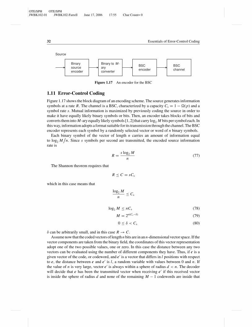
Binarysourceencoder
Binary to M-aryconverter
BSCencoder
BSCchannel
Source
Figure 1.17 An encoder for the BSC
1.11 Error-Control Coding
Figure 1.17 shows the block diagram of an encoding scheme. The source generates informationsymbols at a rate R. The channel is a BSC, characterized by a capacity Cs = 1 − �(p) and asymbol rate s. Mutual information is maximized by previously coding the source in order tomake it have equally likely binary symbols or bits. Then, an encoder takes blocks of bits andconverts them into M-ary equally likely symbols [1, 2] that carry log2 M bits per symbol each. Inthis way, information adopts a format suitable for its transmission through the channel. The BSCencoder represents each symbol by a randomly selected vector or word of n binary symbols.
Each binary symbol of the vector of length n carries an amount of information equalto log2 M
/n. Since s symbols per second are transmitted, the encoded source information
rate is
R = s log2 M
n(77)
The Shannon theorem requires that
R ≤ C = sCs
which in this case means that
log2 M
n≤ Cs
log2 M ≤ nCs (78)
M = 2n(Cs−δ) (79)
0 ≤ δ < Cs (80)
δ can be arbitrarily small, and in this case R → C.
Assume now that the coded vectors of length n bits are in an n-dimensional vector space. If thevector components are taken from the binary field, the coordinates of this vector representationadopt one of the two possible values, one or zero. In this case the distance between any twovectors can be evaluated using the number of different components they have. Thus, if c is agiven vector of the code, or codeword, and c′ is a vector that differs in l positions with respectto c, the distance between c and c′ is l, a random variable with values between 0 and n. Ifthe value of n is very large, vector c′ is always within a sphere of radius d < n. The decoderwill decide that c has been the transmitted vector when receiving c′ if this received vectoris inside the sphere of radius d and none of the remaining M − 1 codewords are inside that

OTE/SPH OTE/SPHJWBK102-01 JWBK102-Farrell June 17, 2006 17:55 Char Count= 0
Information and Coding Theory 33
sphere. Incorrect decoding happens when the number of errors produced during transmissionis such that the received vector is outside the sphere of radius d and lies in the sphere of anothercodeword different from c. Incorrect decoding also occurs even if the received vector lies inthe sphere of radius d , but another codeword is also inside that sphere. Then, the total errorprobability is equal to [5]
Pe = Ple + Pce (81)
where Ple is the probability of the fact that the received vector is outside the sphere of radius dand Pce is the probability that two or more codewords are inside the same sphere. It is noted thatthis event is possible because of the random encoding process, and so two or more codewordscan be within the same sphere of radius d.
Ple is the probability of the error event l ≥ d. Transmission errors are statistically indepen-dent and happen with a probability p < 1/2, and the number of errors l is a random variablegoverned by the binomial distribution
l = np, σ 2 = n(1 − p)p (82)
If the sphere radius is adopted as
d = nβ, p < β < 1/2 (83)
it is taken as slightly larger than the number of expected errors per word. The error probabilityPle is then equal to
Ple = P (l ≥ d) ≤(
σ
d − l
)2
= p(1 − p)
n(β − p)2(84)
and if the conditions expressed in (83) are true, then Ple → 0 as n → ∞.
On the other hand, in order to estimate the error probability, a number m is defined todescribe the number of words or vectors contained within the sphere of radius d surrounding aparticular one of the M codewords. As before, Shannon assumed a random encoding techniquefor solving this problem. From this point of view, the remaining M − 1 codewords are inside then-dimensional vector space, and the probability that a randomly encoded vector or codewordis inside the sphere containing m vectors is
m
2n(85)
Apart from the particular codeword selected, there exist M − 1 other code vectors, so thatusing equation (79)
Pce = (M − 1) m 2−n < M m 2−n < m 2−n 2n(Cs−δ)
= m 2−n 2n[1−�(p)−δ] = m 2−n[�(p)+δ](86)
All the m vectors that are inside the sphere of radius d, defined around the codeword c, haved different positions with respect to the codeword, or less. The number of possible codewordswith d different positions with respect to the codeword is equal to
(nd
). In general, the number

OTE/SPH OTE/SPHJWBK102-01 JWBK102-Farrell June 17, 2006 17:55 Char Count= 0
34 Essentials of Error-Control Coding
m of codewords inside the sphere of radius d is
m =d∑
i=0
(ni
)=
(n0
)+
(n1
)+ · · · +
(nd
), d = nβ (87)
Among all the terms in the above expression, the term(n
d
)is the largest, and it can be
considered as a bound on the sum of the d + 1 other terms as follows:
m ≤ (d + 1)
(nd
)= n!
(n − d)!d!(d + 1) (88)
Since d = nβ, and by using the Stirling approximation for the factorial number n! (n! ≈nn e−n
√2πn if n � 1),
m ≤ (d + 1)
(nd
)= 2n�(β) nβ + 1√
2πnβ(1 − β)
and by combining it with expression (86),
Pce ≤ nβ + 1√2πnβ(1 − β)
2−n[δ+�(p)−�(β)] = nβ + 1√2πnβ(1 − β)
2−n{δ−[�(β)−�(p)]} (89)
The above expression says that the random coding error probability Pce tends to zero if δ >
�(β) − �(p), which is a function of the parameter p, the error probability of the BSC, and ifn → ∞. Once again the error probability tends to zero if the length of the codeword tends toinfinity. The value of the parameter δ is the degree of sacrifice of the channel capacity, and itshould fit the condition 0 ≤ δ < Cs.
Finally, replacing the two terms of the error probability corresponding, respectively, to theeffect of the noise and to the random coding [5], we obtain
Pe = Ple + Pce ≤ p(1 − p)
n(β − p)2+ nβ + 1√
2πnβ(1 − β)2−n{δ−[�(β)−�(p)]} (90)
For a given value of p, if β is taken according to expression (83), and fitting also the conditionδ > �(β) − �(p), then δ′ = δ − [�(β) − �(p)] > 0 and the error probability is
Pe = Ple + Pce ≤ K1
n+ √
nK2 2−nK3 + K4√n
2−nK3 (91)
where K1, K2, K3 and K4 are positive constants. The first and third terms clearly tend to zero
as n → ∞, and the same happens with the term√
nK2 2−nK3 =√
nK2
2nK3if it is analysed using the
L’Hopital rule. Hence, Pe → 0 as long as n → ∞, and so error-free transmission is possiblewhen R < C.
1.12 Limits to Communication and their Consequences
In a communication system operating over the additive white Gaussian noise (AWGN) channelfor which there exists a restriction on the bandwidth, the Nyquist and Shannon theorems areenough to provide a design framework for such a system [5, 7].

OTE/SPH OTE/SPHJWBK102-01 JWBK102-Farrell June 17, 2006 17:55 Char Count= 0
Information and Coding Theory 35
M-aryencoder
Signalgenerator
Channel,C
x(t) y(t)
C = B log2(1 + S / N )
Signaldetector
M-arydecoder
Source
R = (log2 M) / T
M = 2RT
Figure 1.18 An ideal communication system
An ideal communication system characterized by a given signal-to-noise ratio PPN
= SN and
a given bandwidth B is able to perform error-free transmission at a rate R = B log2(1 + S/N ).The ideal system as defined by Shannon is one as seen in Figure 1.18 [5].
The source information is provided in blocks of duration T and encoded as one of the Mpossible signals such that R = log2 M
/T . There is a set of M = 2RT possible signals. The
signal y(t) = x(t) + n(t) is the noisy version of the transmitted signal x(t), which is obtainedafter passing through the band-limited AWGN channel. The Shannon theorem states that
limPe→0
limT →∞
log2 M
T= B log2
(1 + S
N
)(92)
The transmission rate of the communication system tends to the channel capacity, R → C ,if the coding block length, and hence the decoding delay, tends to infinity, T → ∞. Then,from this point of view, this is a non-practical system.
An inspection of the expression C = B log2 (1 + S/N ) leads to the conclusion that both thebandwidth and the signal-to-noise ratio contribute to the performance of the system, as theirincrease provides a higher capacity, and their product is constant for a given capacity, and sothey can be interchanged to improve the system performance. This expression is depicted inFigure 1.19.
For a band-limited communication system of bandwidth B and in the presence of whitenoise, the noise power is equal to N = N0 B, where N0 is the power spectral density of thenoise in that channel. Then
C
B= log2
(1 + S
N0 B
)There is an equivalent expression for the signal-to-noise ratio described in terms of the
average bit energy Eb and the transmission rate R.
If R = C then
Eb
N0
= S
N0 R= S
N0C(93)
C
B= log2
(1 + Eb
N0
C
B
), 2C/B = 1 + Eb
N0
(C
B
)(94)
Eb
N0
= B
C
(2C/B − 1
)(95)
OTE/SPH OTE/SPHJWBK102-01 JWBK102-Farrell June 17, 2006 17:55 Char Count= 0
36 Essentials of Error-Control Coding
0 2 4 6 8 10 12 14 16 18 2010−1
1
10
S/N (dB)
C/B bps/Hz
1
2
4
Realisable region
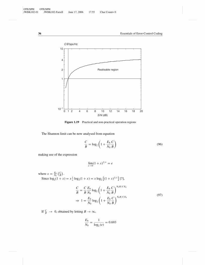
Figure 1.19 Practical and non-practical operation regions
The Shannon limit can be now analysed from equation
C
B= log2
(1 + Eb
N0
C
B
)(96)
making use of the expression
limx→0
(1 + x)1/x = e
where x = Eb
N0
(CB
).
Since log2(1 + x) = x 1x log2(1 + x) = x log2
[(1 + x)1/x
][7],
C
B= C
B
Eb
N0
log2
(1 + Eb
N0
C
B
)N0 B/C Eb
⇒ 1 = Eb
N0
log2
(1 + Eb
N0
C
B
)N0 B/C Eb(97)
If CB → 0, obtained by letting B → ∞,
Eb
N0
= 1
log2 (e)= 0.693

OTE/SPH OTE/SPHJWBK102-01 JWBK102-Farrell June 17, 2006 17:55 Char Count= 0
Information and Coding Theory 37
or (Eb
N0
)dB
= −1.59 dB (98)
This value is usually called the Shannon limit. This is a performance bound on the value ofthe ratio Eb
/N0, using a rather sophisticated coding technique, and for which the channel
bandwidth and the code length n are very large. This means that if the ratio Eb
/N0 is kept
slightly higher than this value, it is possible to have error-free transmission by means of theuse of such a sophisticated coding technique.
From the equation
2C/B = 1 + Eb
N0
(C
B
)(99)
a curve can be obtained relating the normalized bandwidth B/C (Hz/bps) and the ratio Eb
/N0.
For a particular transmission rate R,
2R/B ≤ 1 + Eb
N0
(R
B
)(100)
Eb
N0
≥(
B
R
) (2R/B − 1
)(101)
Expression (100) can be also depicted, and it defines two operating regions, one of practicaluse and another one of impractical use [1, 2, 5, 7]. This curve is seen in Figure 1.20, whichrepresents the quotient R/B as a function of the ratio Eb/N0. The two regions are separated bythe curve that corresponds to the case R = C [equation (99)]. This curve shows the Shannonlimit when R/B → 0. However, for each value of R/B, there exists a different bound, whichcan be obtained by using this curve.
Eb/N0 (dB)
0.10
1
10
100
R/B
−10 10 20 30 40 50
Practical region
Non-practicalregion
Bound –1.59 dB
0
Figure 1.20 Practical and non-practical operation regions. The Shannon limit

OTE/SPH OTE/SPHJWBK102-01 JWBK102-Farrell June 17, 2006 17:55 Char Count= 0
38 Essentials of Error-Control Coding
Bibliography and References
[1] Shannon, C. E., “A mathematical theory of communication,” Bell Syst. Tech. J., vol. 27,pp. 379–423, 623–656, July and October 1948.
[2] Shannon, C. E., “Communications in the presence of noise,” Proc. IEEE, vol. 86, no. 2,pp. 447–458, February 1998.
[3] McEliece, R. J., The Theory of Information and Coding, Addison-Wesley, Massachusetts,1977.
[4] Abramson, N., Information Theory and Coding, McGraw-Hill, New York, 1963.[5] Carlson, B., Communication Systems: An Introduction to Signals and Noise in Electrical
Communication, 3rd Edition, McGraw-Hill, New York, 1986.[6] Proakis, J. G. and Salehi, M., Communication Systems Engineering, Prentice Hall, New
Jersey, 1993.[7] Sklar, B., Digital Communications, Fundamentals and Applications, Prentice Hall, New
York, 1993.[8] Proakis, J. G., Digital Communications, 2nd Edition, McGraw-Hill, New York, 1989.[9] Adamek, J., Foundations of Coding: Theory and Applications of Error-Correcting Codes
with an Introduction to Cryptography and Information Theory, Wiley Interscience, NewYork, 1991.
�
Problems
1.1 A DMS produces symbols with the probabilities as given in Table P.1.1.
Table P.1.1 Probabilities of the
symbols of a discrete source
A 0.4
B 0.2
C 0.2
D 0.1
E 0.05
F 0.05
(a) Find the self-information associated with each symbol, and the entropy ofthe source.
(b) Calculate the maximum possible source entropy, and hence determine thesource efficiency.
1.2 (a) Calculate the entropy of a DMS that generates five symbols {A, B, C, D, E }with probabilities PA = 1/2, PB = 1/4, PC = 1/8, PD = 1/16 and PE =1/16.
(b) Determine the information contained in the emitted sequence DADED.

OTE/SPH OTE/SPHJWBK102-01 JWBK102-Farrell June 17, 2006 17:55 Char Count= 0
Information and Coding Theory 39
1.3 Calculate the source entropy, the transinformation I (X, Y) and the capacity ofthe BSC defined in Figure P.1.1.
p = 0.25 p = 0.25
0
1
P(0) = α = 0.2
P(1) = 1− α = 0.8
1 − p = 0.75
1 − p = 0.75
Figure P.1.1 A binary symmetric channel
1.4 Show that for the BSC, the entropy is maximum when all the symbols of thediscrete source are equally likely.
1.5 An independent-symbol binary source with probabilities 0.25 and 0.75 is trans-mitted over a BSC with transition (error) probability p = 0.01. Calculate the equiv-ocation H (X/Y) and the transinformation I (X, Y).
1.6 What is the capacity of the cascade of BSCs as given in Figure P.1.2?
0
0.1 0.1 0.1 0.1
0.9 0.9
0.90.91
0
1
P(0) = α
P(1) = 1 − α
Figure P.1.2 A cascade of BSCs
1.7 Consider a binary channel with input and output alphabets {0, 1} and the transi-tion probability matrix:
Pch =[3/5 2/51/5 4/5
]Determine the a priori and the two a posteriori entropies of this channel.
1.8 Find the conditional probabilities P(xi /yj ) of the BEC with an erasure probabil-ity of 0.469, when the source probabilities are 0.25 and 0.75. Hence find theequivocation, transinformation and capacity of the channel.
1.9 Calculate the transinformation and estimate the capacity of the non-symmetricerasure channel given in Figure P.1.3.
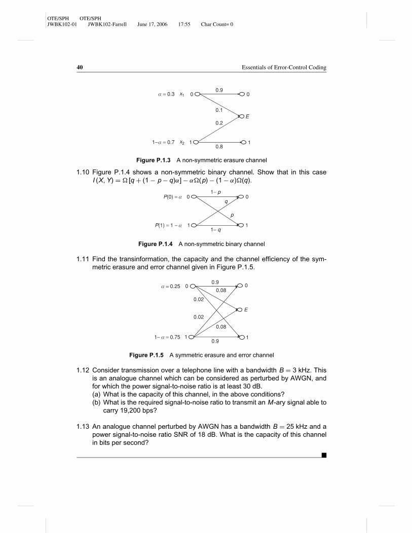
OTE/SPH OTE/SPHJWBK102-01 JWBK102-Farrell June 17, 2006 17:55 Char Count= 0
40 Essentials of Error-Control Coding
0.1
0
11−α = 0.7
α = 0.3 0
1
E
x1
x2
0.9
0.8
0.2
Figure P.1.3 A non-symmetric erasure channel
1.10 Figure P.1.4 shows a non-symmetric binary channel. Show that in this caseI (X, Y) = � [q + (1 − p − q)α] − α�(p) − (1 − α)�(q).
P(0) = α
P(1) = 1 − α
0
1
0
1
p
q
1− p
1− q
Figure P.1.4 A non-symmetric binary channel
1.11 Find the transinformation, the capacity and the channel efficiency of the sym-metric erasure and error channel given in Figure P.1.5.
0.9
0.9
0.08
0.08
00
1
E
0.02
0.02
11− α = 0.75
α = 0.25
Figure P.1.5 A symmetric erasure and error channel
1.12 Consider transmission over a telephone line with a bandwidth B = 3 kHz. Thisis an analogue channel which can be considered as perturbed by AWGN, andfor which the power signal-to-noise ratio is at least 30 dB.(a) What is the capacity of this channel, in the above conditions?(b) What is the required signal-to-noise ratio to transmit an M-ary signal able to
carry 19,200 bps?
1.13 An analogue channel perturbed by AWGN has a bandwidth B = 25 kHz and apower signal-to-noise ratio SNR of 18 dB. What is the capacity of this channelin bits per second?
�