infocentre - geoscience.nt.gov.au area report on a seismic reflection survey conducted in op-179/175...
TRANSCRIPT

Petroleum Exploration ReportsThis file contains scanned images of hardcopy reportsdata submitted to the Northern Territory Government under Petroleum Legislation
Bringing Forward DiscoveryThis information is made available to assist future petroleum explorers and may be distributed freely
Scanning informationThe quality of the scan reflects the condition of the original hardcopy reportdata
InfoCentreCall +61 8 8999 6443
Click geoscienceinfontgovauwwwmineralsntgovau
Visit 3rd floorCentrepoint BuildingSmith Street MallDarwin Northern Territory 0800
InfoCentreNT Minerals and Energy
BRINGING FORWARD DISCOVERYIN AUSTRALIArsquoS NORTHERN TERRITORY
A09-093indd
FIELD AREA REPORT
ON A
SEISMIC REFLECTION SURVEY
CONDUCTED IN
OP-179175 AND OP-189
FOR
MAGELLAN PETROLEUM AUSTRALIA LIMITED
BY
SEISMOGRAPH SERVICE LIMITED
PARTY 179
DURING THE PERIOD
31ST DECEMBER 1981 TO 25TH FEBRUARY 1982
CONTENTS
Page Number
SYNOPSIS 1middot middot INTRODUCTION 1middot middot middot TERRAIN AND LOGISTICS 1
PERMITTING AND DAMAGES bull bull middot middot 2
SURVEYING 2middot CONTROL AND TECHNIQUE middot middot 3
LINE CLEARING 3middot middot middot WEATHERING CONTROL 4middot COMPUTING 4middot middot middot middot RECORDING 5middot middot middot middot PROCESSING middot middot 7
RECOMMENDATIONS AND COMMENTS 7middot DISTRIBUTION 8middot middot LIST OF APPENDICES AND ENCLOSURES 9middot
MAP
SHOWING PROSPECT LOCATION
DEC1981- FEB 1982 SSL CON 179
II N T I I I ALICE SPRINGS
Mereenie Field ~ ~ ~____---_L_ I I I I I 1------_- _I -l-I
I1-___
I -
~ Permits 178175
Page 1
SYNOPSIS
Magellan Petroleum Australia Limited contracted Seismograph Service Limited to conduct a Vibroseis reflection survey in the Mereenie and Ooraminna prospect areas of OP-175l79 and 189 between 31st December 1981 and 25th February 1982
Much of the work was designed to pin point faults bisecting the area and to further delinate known hydrocarbon bearing structures
Data quality was fair to good and a reasonable rate of progress was achieved Substantial and prolonged rains delayed the completion of the Ooraminna survey
INTRODUCTION
The Mereenie prospect area lies within the Amadeus Basin approximately 230 kilometres WSW of Alice Springs Mobilisation to the field camp location was undertaken on the 19th December from Alice Springs Numerous washouts along the track leading to the camp site at West Mereenie No 2 Well delayed the mobilisation After a break for the Christmas holidays an experimental programme was started on Line 08 on the 31st December this was supervised by the Clients Representative Mr G Gibson and Mr J Earle Production recording commenced on the 1st January and continued at a satisfactory rate of progress 1863 kilometres of surface coverage was recorded
A further 193 kilometres was recorded on the Ooraminna prospect 50 kilometres south of Alice Springs This programme was split into eastern and western portions both being extensions to previous seismic surveys The crew was placed on standby for 10 days during a period of unusually severe rain
TERRAIN AND LOGISTICS
The Mereenie portion of the survey was conducted from a single location comprising camp equipment listed in Appendix 2 located at drill site WM-2 (See Enclosure 1) Access was by dirt road to Alice Springs which was upgraded due to the mobilisation of a drilling rig into the immediate area Vehicle travel time was usually 3 to 4 hours
The seismic lines ran in the valley between two steeply sided bluffs and terrain in the valley floor consisted of smaller undulating sand dunes and sandstone outcrops Spinifex coarse mulga grasses and occasional white and ironwoods were the typical vegetation found in both prospect areas
Page 2
Fuel was ordered through the crew Administrator who had an office in the Magellan premises in Alice Springs Diesel was supplied in bulk form and stored in an overhead tank Super grade petrol was supplied and stored in drums
Food was purchased in Alice Springs on a weekly basis and transported by SSL Load Carrier All other mechanical and recording supplies were ordered from Alice Springs and Adelaide
Explosives for the weathering crew were obtained from Centralian Industries and delivered to the crew by Mr C Freer of Alice Springs
Obtaining a regular camp water supply was difficult initially but once the bore supply to the drilling rig had been successfully connected no further problems ensued
Accommodation messing and office premises were available at the Oasis Motel Alice Springs during the Ooraminna survey
Auxiliary staff were recruited in Alice Springs and worked continuously for 3 weeks before taking one weeks leave Chartair Proprietary Limited was subcontracted to provide air transport between Alice Springs and the camp airstrip This service was provided twice weekly The aircraft were also used to carry small items of freight and crew mail
Staff also worked a rotational leave system and used Adelaide as their leave centre
PERMITTING AND DAMAGES
Permitting was undertaken by Magellan prior to the crews arrival Since the prospects were within aboriginal lands close liaison between the Surveyors and Central Lands Council (CLC) advisors was necessary All lines were set out before bulldozing commenced and approval was granted once it had been ascertained that no sites of significance to the aboriginal community were effected
Magellan also produced an environmental report which detailed strict practices to which the survey had to comply These were mainly concerned with minimising the damage done to natural vegetation and a rehabilitation programme is to be conducted once seismic operations are completed
No damages were reported to SSL staff during this years survey
SURVEYING
All lines were chained using a 100 metre steel wire rope which was checked against an Invar band 18 white painted wooden pegs bearing line and station number marked in black indelihle ink
Page 3
were placed at 50 metre intervals Four foot steel fence postSt firmly driven into the ground and bearing a securely fixed t dye stamped tag were used as permanent markers (PM) Tags denoted line t year and PM position PMs were placed at the ends of all lines intersections and at 5 kilometre intervals A list of these markers is given in Appendix 5
CONTROL AND TECHNIQUE
18635 kilometres of line was surveyed at Mereenie and a further 193 kilometres at Ooraminna
Levelling was carried out by tacheometry Due to the undulating terrain this took a considerable time as a large number of observations were reduced to a few hundred metres (horizontal) Traversing was between sunshots at end of lines and these were tied by observing included angles
Control at Mereenie was provided by a well block located in the centre of the prospect Heights were to Australian Mean Sea Level and co-ordinates were in the Australian Map Grid Zone 52
Control at Ooraminna proved to be further distant than is usually practical but with the arrival of EDM equipment it was possible to traverse from a second order trig station 15 kilometres south of the prospect Vertical control was taken from a bench mark located at Limestone Bore
Control for Lines SO-l and SO-2 was taken from a previous GSI PM located on the end of Line P80-l4
LINE CLEARING
Earthmoving was subcontracted by Magellan to GIG Favaro Equipment Proprietary Limited of Alice Springs Initially one Komatsu 085A and one grader 012E were employed but the inexperience of the Operators often necessitated recutting of lines which were unsatisfactory and caused a generally slow progress rate An extra machine (Caterpillar 09) was employed from United Mining and Construction Proprietary Limited to improve the cleared line laid The more experienced new Operator dramatically improved both line quantity and quality
The bulldozers worked throughout under the supervision of the Surveyors Lines were set out by turned angle from existing lines and sun shots Magnetic bearings were used on the short Lines 16 18 20 22 and 24 Operators maintained straight lines by back sighting onto fence pickets placed in the centre of the track The grader was used to make a final cut once tree felling and bulk earthmoving had been completed The grader was not used on sand dunes
r
Page 4
For most of the prospect the machines operated independently Only on the long eastwest Line 11 did both machines combine
The Ooraminna prospect gave no bulldozing problems Poor access between Pinch Bore and Limestone Bore considerably increased travel time during the recording of the eastern lines (See Enclosure 2)
WEATHERING CONTROL
Weathering control specified by Magellan was continuous rfraction aurfac covra with a thouand bullbulltrbullbullpiit aprad and moveup of 500 tre A lona offet to the neareat tation was chosen by the Client and this ant that no hallow information wa available by this ethod Several short apreada were recorded to provide the necellary control These tied well with uphole results
Upholes were recorded at line intersections and at 5 kilometre intervals to provide control Por each uphole a time limit of It hours was imposed on the scout 250 rig supplied by Gorey and Cole of Alice Springs as drilling was often difficult The result was that only one third of the holes drilled were deeper than 15 metres Shots were taken every 3 metres up the hole
The rig was also used to drill shallow 3 metre holes for the refraction shots 2 kilogrammes of Anzite Blue explosive were shot into the 24 SK-4 geophones connected individually along the spread Dry write paper records were produced after filtering and amplification in the 010 recording instruments
Eight 6 takeout cables were normally used which meant that four cables could be moved whilst the remainder were used for recording
This enabled the crew to record in excess of 10 kilometres per day
COMPUTING
Graphs were plotted of the first arrival times at each geophone against distance to that geophone from the source The slope of the reSUlting graph indicated velocities of propogation through the weathered layers The first layer (Vo) was found to have a value of 700 metres per second at Mereenie and 900 metres per second at Ooraminna
Depth of weathering was derived from the formulae
VIVo T z shy 22 j(Vl)2 (Vo)
r-r
Page 5
and
Zl _ Tl - Zo JV22
- V02
-2shy V2Vo
V2Vl
j(V2)2 _ (Vl)2
where
Z - Thickness of 1st Weathered Layer Zl - Thickness of 2nd Layer Vo - Weathering Velocity VI - Sub Weatheing v2 - Elevation Velocity T - Intercept Time lVl in milliseconds Tl- - Intercept Time 1V2 in milliseconds
The thicknes of the first weathered layer (z) was typically 8 metres at Mereenie and Ooraminna north west and 18 metres at Ooraminna south east
In both areas a second layer was detected having a velocity in the range 1500 to 2700 metres per second and thickness varying between 10 to 75 metres Elevation velocity was consistently greater than 2800 metres per second
Datum level was 650 metres at Mereenie 440 metres at Ooraminna north west and 500 metres at Ooraminna south east A listing of the calculator programme used in the computing of statics is given in Enclosure 4
RECORDING
Three sets of recording parameter experiments were conducted during the survey two at Mereenie and one at Ooraminna
The first noise spread consisting of 24 patches of 12 bunched geophones at 417 metre separation was laid on Line 08 between pegs 1002 and 04 on the 31st December 1981 A single vibrator sweeping 60-10 Hz in l6s was used to vibrate at 15 separate stations from 1004 to 1032 The correlated 24 trace paper records were taken by the Client who performed the noise analysis
Two geophone patterns were laid alongside each other for purposes of comparing attenuation of the main noise events These patterns wereshy
(a) No 1-24 weighted 1111122332211111 58 metres between geophones 87 metres pattern
(b) No 25-48 linear 39 metres between geophones (897 metres pattern)
Page 6
Three vibrators were then used with the following variations
1 After vibrator spacing (11 15 20 30 40 metres) keep moveups constant (75 metres)
2 Increase number of sweeps to 16 keep to 30 metre spacing vary moveups (1 2 37 6 metres)
3 Keeping moveups and spacing constant change sweep to 50-16 Hz
The above comparisons were conducted at station 1030 Line 08 Moving to station 1040 the best looking parameters resulting from the previous comparisons were recorded into both geophone arrays
On the visual evidence of the correlated paper records it was decided the non weighted pattern gave overall better results
At the Clientts request Line 08 was recorded 2400 fold coverage from stations 1000-1060 and the field tapes were despatched immediately to Brisbane for processing
A further noise spread was recorded on the 2nd January on Line 10 This followed the same format as that previously recorded on Line 8 24 patches of 12 bunched geophones were laid between stations 1048 and 1050 and a single vibrator was used to sweep 50-16 liz every 100 metres from 1050 to 1068 The noise record analysis was performed by the Client A list of line by line parameters is given 1n Appendix 4 for both prospects
A steady increase in the rate of production was achieved during January GeophontHt were moved by 3 Toyota plekuIHJ manllud by 9 workers and a further 3 men moved cables by Bedford truck
Instrument and vibrator similarity tests were performed daily to ensure correct performance of the recording equipment An oscilloscope was used continuously to monitor summing and noise cancellation functions 24 traces of each recorded VP were displayed on dry write paper in correlated form Incoming raw data was amplified and digitised by the Sercel 338 HR summed in the Addit III and then dumped at the end of each VP back into the Sercel for formatting and recording onto til magnetic tapes in SEG B phase encoded form
Line recording order was originally determined by the Client but once initial priorities were complete a more logistical approach was made to minimise travel times Rain during the latter half of January caused minor delays but the considerably heavier rain during February forced the closure of the recording section for 10 days
Recording on the Ooraminna prospect was completed on the 25th February
Page 7
PROCESSING
Field recorded magnetic tapes were despatched twice weekly by air from the field camp to the Administrators Office in Alice Springs From here they were despatched to the Petty Ray Geophysical Company at 91 Edward Street Brisbane by airfreight courier service
RECOMMENDATIONS AND COMMENTS
The difference between experienced and non experienced bulldozer operators was markedly demonstrated during the survey More care is needed when choosing a subcontractor who should be able to supply and maintain equipment and personnel suitable for seismic line clearing
If many of this years survey control problems are to be overcome additional control should be established at regular intervals throughout the prospect area This will lead to an overall increase in survey accuracy and decrease in the time spent bringing in distant control stations
PM Farrell Party Chief
KA Potts Supervisor Australia
M5216 MWCJH 11th May 1982
Page 8
DISTRIBUTION
Magellan Petroleum Australia Limited 10 Coples
Seismograph Service Limited Holwood 1 Copy
Seismograph Service Limited Australia 1 Copy
Page 9
LIST OF APPENDICES AND ENCLOSURES
Appendix 1 Personnel
Appendix 2 Equipment
Appendix 3 Statistics
Appendix 4 Recording Parameters by Line
Appendix 5 List of Permanent Markers
Enclosures 1 amp 2 Seismic Line Location Maps
Enclosure 3 Recording Format Diagram
Enclosure 4 Statics Programme (HP4lCV)
Enclosure 5 (Mereenie) Horizontal Vertical Loop Closure Diagram
Appendix 1
LIST OF PERSONNEL
Technical Staff (includes leave reliefs and replacements)
Party Chief
ComputerDeputy Party Chief
Computers
Assistant Computer
Senior Observer
Observers
Assistant Observers
Technical Assistant
Mechanics
Surveyors
Administrators
Auxiliary Staff
Cooks Cooks Assistant Vibrators Operators Drivers Utility Workers Survey Labour Refraction Crew Mechanics Assistant
Additional to Contract at no
Survey TechnLcal Assistant
PM Farrell
S Mathis
I Donnelly A Oldham
T Perrin
K Filer
MT Jenkins DJ Lewis I Heathfield
P Spragg A Colquhoun P Doogan
PC Harris
R Provis HD Jacobs FB Vitnell
DT Armstrong GD Leith CW Butler D Howe
RK Algie A Bauer
2 2 5 6
12 4 6 (4 Additional to Contract) 1
charge to Client
T bull Jackson (9-18 Ja nua ry )
Appendix 2
EQUIPMENT
4 Failing Y900 Vibrators on International 6 x 6 Pays tar 5000s 1 Bedford 4 x 4 Recording Truck 2 Bedford 4 x 4 Workshop Trucks 2 Bedford 4 x 4 Water Trucks 2 Bedford 4 x 4 Load Carriers 1 Bedford 4 x 4 Load Carrier and Mobile Crane 2 Toyota 4 x 4 Hard-top Vehicles (1 Additional to Contract)
10 Toyota 4 x 4 Pick-ups (2 Additional to Contract) 1 Toyota 4 x 4 LVL Recording Truck 1 Car (for Administrator) 1 Stores Trailer 1 Mess Trailer 1 Kitchen Trailer 2 Shower Trailers 2 Office Trailers 2 Toilet Trailers 2 Static Water Tank Trailers 1 Observers Workshop Trailer 1 MessKitchen Trailer 2 10 Man Accommodation Bunkhouses (Additional to Contract) 1 Sercel 338 HR Digital Recording System 48 Trace 1 InputOutput Rotalong Switch 1 SmJ 400 Electrostatic Oscllograph 48 Trace 1 Addit III Digital Compositor 1 Quantum Correlator 24 Trace 1 Pelton Sweep Encoder 5 Pelton Advance I Mk IV Vibrator Electronics
14 VHF Radios (2 Additional to Contract) 25 110 Conductor CDP Cables 48 Trace 100 metre intervals
2304 Geophones in Strings of 12 SM4 10 Hz 1 OYO Refraction AmplifierBlasterOscillograph System
24 Trace 8 Spread Cables 12 Trace (Property of International Oil) 2 Wild Tl-A Theodolites 6 SSB Radios (2 Additional to Contract) 1 Complete Set Electronic Test Equipment
STATISTICS
Mereenie
Survey Oates 211281 to 20182 (Chaining only)
LVLUpho1e Dates 311281 to 23182
Recording Oates 311281 to 4282
Kilometres Chained 18635
Kilometres Recorded 1863
Sweeps Recorded 26540
VPs Recorded 1986
LVL Spreads Recorded 378
Upholes Recorded 36
Days Mobilisation 1
Demobilisation 2
Days Recording Production 33t
Hours Recording 32215
Hours Travel 3135
Total Hours (Contract) 37350
Kilometres per Recording 556 Day
VPs per Recording 593 Day
Standby Oates (Reduced Fee)
Damage Payments Nil
Appendix 3
Oorammena
3282 to 6282
6282 to 9282
8282 to 26282
193
193
3696
231
50
3
1
6250
3040
10330
257
3080
112 to 202
Nil
( c (
MEREENIE PROSPECT Appendix 4
GeoEhone SEre ad Vibrator Line Stations Coverage Fo1d Interval Pattern Details Pattern Dates
M82-08 1000-1008 04 2400 50 m A A A 1st January 1982 100S-1060 26 2400 50 m A B A
MS2-0S 1060-1170 55 1200 50 m A B A 1st- 2nd January MS2-10 1000-1090 45 1200 50 m A B A 3rd- 4th January MS2-13 1000-1200 100 1200 50 m A B A 4th- 6th January MS2-15 1014-1290 13S 1200 50 m A B A 6th- 9th January MS2-14 1001-1075 37 1200 50 m A B A 9th January MS2-09 1163-1007 78 1200 50 m A B A 10th-11th January MS2-07 1250-1024 113 1200 50 m A B A 12th-14th January MS2-12 1097-1001 48 1200 50 m A B B 14th-15th January MS2-05 1120- 974 73 1200 50 m A B B 15th-16th January MS2-03 10S2-1002 40 1200 50 m A B B 16th-17th January MS2-01B l1S5-1001 92 1200 50 m A B B 17th-18th January 1-182-20 1169-1001 84 1200 50 m A B B 18th-19th January M82-04 1000-1150 75 1200 50 m A B B 19th-20th January M82-22 1165-1001 82 1200 50 m A B B 21st-22nd January MS2-02 1000-1166 83 1200 50 m A B B 22nd-23rd January MS2-1A 1290-1000 145 1200 50 m A B B 23rd-25th January 1-182-24 1149-1001 74 1200 50 m A B B 27th-28th January M82-11 1510-1004 253 1200 50 m A B B 28th- 1st February M82-6 1006-1180 87 1200 50 m A B B 1st- 2nd February
( c (
Appendix 4 - Page 2
Ge02hone S2read Vibrator Line Stations Coverage Fo1d Interval Pattern Details Pattern Dates
M82-10 1013- 928 425 1200 50 m A B B 2nd- 3rd February Ext M82-16 1000-1086 43 1200 50 m A B B 3rd- 4th February M82-18 1096-1001 475 1200 50 m A B B 4th February
Geophone Pattern
A - 24 x SM4 geophones 2 strings of 12 in series connected in parallel linear over 90 metres 39 metre separation
S2read Details
A = 1400-250-0-250-1400 metres
B = 1300-150-0-150-1300 metres
Vibrator Pattern
A 3 x Y900s 30 metre pad to pad 1 metre moveup centred on peg 16 s~eeps 50-16 Hz16 seconds 75 metres pattern length
( ( (
Appendix 4 - Page 3
B = 3 x Y900s 30 metre pad to pad 1 metre moveup centred on peg 12 sweeps per VP 71 metres pattern length
OORAMINNA PROSPECT
Geo~hone S~read Vibrator Line Stations Covera~ Fold Interval Pattern Details Pattern Dates
01 1004-1100 48 12 50 A A A 8th-10th 02 1000-1l00 50 12 50 A A A 10th-21st 03 1040-1000 20 24 50 A A B 22nd
501 1000-1025 125 24 50 A B B 23rd 502 1000-1125 625 12 50 A A A 23rd-25th
Geophone Pattern
A 24 x SM4 geophones 2 Strings of 12 in series connected in parallel laid in a linear pattern 5 metres separation 115 metres pattern length
S~read Details
B = No gap - whole line live
A = 1400-250-0-250-1400 metres
( ( (
Appendix 4 - Page 4
Vibrator Pattern
A - 3 x Y900 vibrators 14 metres pad to pad 65 metres moveup 1255 metre pattern length centred on peg 16 sweeps 50-16 Hzl6 seconds
B D as A except 325 metre moveup 77 metre pattern length
Appendix 5
MEREENIE PERMANENT MARKER LIST
Peg Descri2tion Elevation Co-ordinates No (m ) E N
Line M-82-1A
1000 SOL 70149 740 171 7 355 749
1020 72258 741 026 7 355 232
1081 PM for INT 730 743 653 7 353 683 1A24
1100 73093 744 472 7 353 201
1144 INT 1A2 73714 746 401 I 1gt2 ObI + 380 m 1200 PM by INT 74075 748 782 7 1)0 667
lA22 1251 PM for INT 75355 750 978 7 349 372
lA4 1270 PM for INT 75910 751 796 7 348 888
lA1B 1290 PM at EOL 76147 752 657 7 348 378
Line M-82-1B
1000 SOL 75425 750 894 7 349 319
1020 PM for INT 75910 751 794 7 348 883 IBIA
1061 PM for INT 75200 753 651 7 347 990 + 11M IB20 1100 77692 755 395 7 347 141
H06 PM for INT 77743 755 691 7 346 996 + 30 1B6 1165 PM for INT 76790 758 315 7 345 716
IB3 H85 EOL 75968 759 214 7 345 276
Line M-82-2
1000 SOL 71512 743 764 7 346 805
1051 PM for INT 74151 744 922 7 349 130 + 48M 211 1066 AT INT GSI 75188 745 241 7 349 756
LINE LGE4A (1981) COMMON P1
-~
Peg No
DescriEtion
Line M-82-2 (Continued)
1100
1117 + 33 1167
PM for INT 21A EOL
Line M-82-3
1002 1020
1038 + 46 1062
SOL PM for INT 3lB and tie to Well WM2 PM for INT 38
PM for INT 35
1082 EOL
Line M-82-4
1000 SOL
1052 INT 411
1100
1108 INT 41A
1150 EOL
Line M-82-6
1006 SOL
1056 + 5M 1090
PM at INT 611
PM beside M-l
1108 + 31M 1159 + 40M 1180
PM at INT
PM at INT
EOL
61B
68
Elevation (m )
73348
73714
75055
77093 76811
75889
74873
73918
72334
75729
75703
75353
75367
74916
75581
78404
77743
75928
75939
Appendix 5 - Page 2
Co-ordinates E N
746 008
746 403
747 490
7 351 274
7 352 066
7 354 279
757 758
589 425
7 345 997 7 345 663
759 299
760 387
761 326
7 345
7 344
7 344
307
920
574
747 927
749 409
750 784
750 955
752 215
7 344 917
7 347 052
7 349 002
7 349 249
7 351 052
753 269
754 447
755 247
755 693
756 917
757 399
7 342 473
7 344 683
7 346 117
7 346 995
7 349 239
7 350 129
-shy
Peg No
Line M-82-5
974
994
1000
1100
1107
1120
Line M-82-7
1023
1041
1067
1100
1149
1200
1231
1250
Line M-82-8
1000
1028 + 2M 1100
1120
1165 + 25 1170
Descrietion
SDL
PM for INT
PM for INT
EDL
SDL
PM for INT
PM for Bend
PM for Bend
PM for INT
EOL
SOL
PM for INT
PM for INT
PM for INT
EDL
53
57
75
79
86
83
810
Elevation (m )
75678
74873
74582
72466
72500
72764
72255
72558
72434
71212
71681
69989
69510
68769
75864
75928
76998
75889
76992
77396
Appendix 5 - Page 3
Co-ordinates E N
759 520 7 345 423
760 384 7 344 920
760 643 7 344 769
764 974 7 342 272
765 280 7 342 102
765 848 7 341 786
764587 7 342 618
765 311 7 342 084
766 357 7 341 312
767 623 7 340 255
769 507 7 338 690
771 618 7 337 257
772 902 7 336 389
773 686 7 335 857
756 182 7 350 434
758 789 7 346 163
759 299 7 345 302
760 458 7 343 344
760 573 7 343 146
~
--_
Peg DescriEtion No
Line M-82-9
1006 SOL
1019 PM at INT 97 + 186 1039 PM at INT 914 +13 1100
1163 EOL
Line M-82-10
928 SOL
1000
1049 PM for INT + 29M 101113 1079 PM for INT + 46t1 108 1090 EOL
Line M-82-11
1005 SOL
1020 PM for INT 111013
1100
1136 PM for INT 116 + 385 1187 PM for INT +11 1120 1200
1248 PM at INT 114 + 8M 1300
1302 PM at INT +11 1122 1347 PM at INT + 8M 1121 1400
Elevation (m )
69631
68728
692 07
66396
73733
77638
76766
76993
76612
77028
76766
75749
75581
75595
75239
75729
76145
75856
74151
70669
Appendix 5 - Page 4
Co-ordinates E N
772 354 7 336 829
772 8735 7 336 407
773 644 7 335 781
775 999 7 333 866
778 453 7 331 891
756 450 7 336 894
758 352 7 339 950
759 661 7 342 055
760 457 7 343 346
760 713 7 343 780
760 324 7 341 708
759 660 7 342 056
756 094 7 343 867
754 448 7 344 682
752 168 7 345 761
751 589 7 346 033
749 412 7 347 053
747 063 7 348 149
746 962 7 348 196
744 921 7 349 133
742 504 7 350 197
Peg No
DescriEtion Elevation (m )
Appendix 5 - Page
Co-ordinates E
5
N
Line M-82-11 (Continued)
1408 PM at INT 1124
1493 INT LllG S1
1500
1510 EDL
L8
70529
69396
69942
742
738
737
737
137
236
916
457
7 350 356
7 352 043
7 352 182
7 352 380
Line M-82-12
1000 SOL
1042 INT 1215 + 41 1046 INT 1213 + 45 1062 BESIDE EM-4 + 34 1068 INT 121
1097 EOL
73408
71415
71232
71093
70037
766 085
767 092
767 188
767 559
767 684
768 379
7 337 241
7 339 130
7 339 310
7 340 006
7 340 240
7 341 512
Line M-82-13
1000 SOL
1020 INT 101113
1100
1169 INT 1315 + 5 1180 INT 1312 + 14 1200 EOL
76569
76766
74057
71434
71239
71508
758 730
759 661
763 407
766 662
767 189
768 124
7 342 418
7 342 053
7 340 654
7 339 497
7 339 312
7 338 998
Line M-82-14
1000 SDL
1029 INT 1415 + 12 1061 INT 149 + 46 1076 EOL
70428
692 15
68723
68300
711 644
772 5861
773 641
774 094
7 333 412
7 334 529
7 335 774
7 336 318
-
-~
Peg Descri)2tion No
Line M-82-15
1014 SOL
1030 PM for INT 1513
1041 INT 1512 + 14 1100
1187 BEND + 23M 1200
1290 EOL
Line M-82-16
1000 SOL
1024 INT 1615
1052 INT 169
1085 EOL
Line M-82-18
1000 SOL
1032 PM for INT 1815
1062 PM for INT 187
1096 EOL
Line M-82-20
1000 SOL
1060 PM for INT 2011
1100
1113 PM for INT + 30M 20IB 1169 EOL
Elevation (m )
72102
71434
71415
71614
69248
69876
69006
70769
68536
69405
677 16
72266
72063
70023
68658
73537
75595
75909
75258
76009
Appendix 5 - Page 6
Co-ordinates N
766 052 7 340 012
766 662 7 339 495
767 092 7 339 130
769 333 7 337 238
772 695 7 334 439
773 219 7 334 089
776 957 7 331 586
774 097 7 332 021
774 864 7 332 932
775 774 7 334 006
776 837 7 335 268
769 832 7 334 715
770 864 7 335 938
771 827 7 337 088
772 920 7 338 390
750 500 7 43 267
752 168 7 345 761
753 276 7 347 421
753 652 7 347 987
755 183 7 350 295
Appendix 5 - Page 7
Peg Descri2tion Elevation Co-ordinates No (m ) E N
Line M-82-22
1000 SOL 72061 745 188 7 345 775
1060 INT 2211 75856 746 963 7 348 193
1100 74102 748 149 7 349 804
1121 INT 221A 74075 748 783 7 350 664 + 18 1165 EOL 75076 758 077 7 352 420
Line M-82-24
1000 SOL 69659 741 038 7 347 888
1054 PM at INT 70529 742 138 7 350 353 2411
1100 73789 743 100 7 352 444
1127 PM at INT 72915 743 639 7 353 679 24lA
1150 EOL 73312 744 092 7 354 735
~ -
OORAMINNA
PERMANENT MARKER LIST
Corrected for SPs 10201025
Peg DescriEtion Elevation No (m)
Line 1
1004 SOL 44189
1090 INT 123 44685
1100 EOL 45003
Line 2
1000 SOL 44906
llOO EOL 45434
Line 3
1000 SOL 44429
1040 EOL 45883
50-1
1000 SOL 50173
1010 + 34
1020
PM for INT SOlS02
50690
1025 EOL 51005
Line 50-2
1000 SOL 50501
1020
1100
PM for INT 501502
50690
50279
1125 EOL 49736
Appendix 5 - Page 8
Co-ordinates E
402 769 7 332 005
402 614 7 332 481
402 458 7 332 956
402 380 7 333 193
401 643 7 332 224
402 600 7 332 513
406 421 7 333 696
407 615 7 334 066
( ( (
~ ~ ~ 6
Diagram Showing Lines at Mereenie Prospect JAN- FEB 1982
fvJ82-1A
2-11 WMl bullM8 ~r-==-~EM~2+7ftrI__J~~ I
M82-15 10 20
J 14 KINGS CANYON
KEY
SEISMiC LINE
bull WELL
x WATER BORE
----- TRACK
FIELD AREA REPORT
CON 179 ENCL No1
( (
Diagram Showing Lines at Ooraminna Prospect FEB 1982
Valley Bore ~ Rd
- 11-gt
bull ~~ bull J~ r Iso~ Atootnenna__~
rEO~ bull
~ore I -- I~~~
--SD2 ~~ SQL ~
~ (P-80-14J 1 ~ SOL Imiddotlt
I -- O---+-- -_ -rffi- t ~~
I_---- ---__- mes one~ Borel ~ I~
KEY _ - shy Tr a (k
~ High Ground
I I
I
Kangar~0 Well ~-=~ ~ ----------MoJNT
MORDRED
FIELD AREA REPORT
CON179 ENCL No2
_ llu _ _ lt~ run~nna )rOnnct3 (ontr1ct 7~)I ror1-~O litin7 tatic om1luta_ ion u~r(w11 ~Md ()
i3itL8L JATB ~2 Wi~ 07 B lflIT
iS 1ST TH gt36 PROMPT l~ u~(L i ~B ilm~ 09 STO fO Ie CUI l LAST qll bull 12 PROIIPT 3 iUn)( 14 AYIEW 15 IlDV 16 STO l I7tlBl 00 I~ SF (l
9 pel BI 28 eLii 21 5TH HO 22 PROIIPT 23 flRCL li 24 I1YIEW 25 STO IND II) 26 XIV 27 CF 89 28 Cll1 29 lt~
38 ARCl X 31 1lIE~
32 2TI) [Hr II
4 12 35 PROHPT 36 I1RCl X 3~ flVIEW 30 ~TO ItUI 12 3) LA 4j IE bull 41 PROIIPT 42 ARCl X 43 flYIEIl 44 ilDY 45 STO INB 13 46 ISI~ Hl 47 ISG II 48 IS( 12 49 ISG J3 58 FC 88 51 eTO 811 S2lBl 81 S3 SF 98 S4 ICl 81 55 ClA 56 STH HO bull 57 PROIIPT S8 I1RCl X 59 IlYIEIi 68 STO HlD 14 61 xlty 62 (f 08 63 ClR 64 DI bull amp5 PPOIIPT 66 flI1Cl X ~~ flYIEIl 69 STO P IS 19 ClA ill f2 bull
I 1n~pr
72 ~(L
73 Am~
~4 AD ~~ ~TO IN]) 16
6 15G 14 77 G 1~
i~ [St 16 7 FC) II) 89 (TO 91 i3I+LBl ~2
B2 SF II~
33 I1CL 91 amp4 (lA 35 STN NO 86 PI10IlPT 87 ARCL x aa I1VIEW 89 STO IHD 17 ~8 )(y
91 CF 98 n ClR 93 ELEV bull 94 PROIIPT lt15 ARCl X AVIEW 97 RDY Iii STO INB IS 99 ISG 17
191) IS 18 Hll Fe 19 i02 GTO 92 183 CUI 194 DATUIt bull 195 PROItPT 136 ARCl X Hl7 AYIEII 198 AIY 199 STO II~ 110 XEIl INIT 111 STH ELEV Dl 12 leI 113 D2 TU 114 IlCR 115 PRBUF 116 ADV 117lBl lHTPl 118 RCl 118 119 RCl IND III 128 XOY 121 RCl IHD III 122 XOV 123 ISG 19 124 RCl lIP III 125 )(=(
126 SF 91 127 Rt 128 shy129 RBH 138 lIOY 131 shy132 Rt 133 I
134 STO 82 135 RCl HiD 11 136 EHTER 137 EHTERt n8 ISG 11 139 ICl IND II 148l10Y 141 shy142 RCl 02 143 44 + 45 STO Pi l41i ~CL INII I 147 EHTE~t
1413 EHint 149 Sl~ 2 ~ peL l
151 X152 - ENCLOSURE 4 153 m 92 1r4 bull 15 156 STO 94 IS7 RCL IN[I 13 1~8 ENTERt 15~ EIITEH 169 1gt( n 161 ~Cl lllII 3 162 xny 163 164 RCl 82 165 166 + 167 TO 85 168 I1CL 811 169 RlL JND 14 170 XOI 171 pel IND 14 172 xm 173 ISG 14 174 RCl 11m 14 175 Xf 176 SF 02 177 Rt 1713 179 I1DN IS8 XOY lSI shy182 Rt 183 I
184 STO 62 HIS I1Cl INB 15 186 EHTERt 187 EHTERt 188 ISG 15 ISCI PCl IHD 15 1ge XOl Ill shy192 PCl 92 193 1~4 + 195 STO tlogt
1 RCl IND IEshy197 EHTERt 198 EHTERt 199 15G 16 296 PCl IND II 2111 XOY
cd RCl 02 284 205 + 286 sro 67 297 RCl 90 288 I(Cl IHB 17 281 XOY 218 RCl INB 17 2I1XOY 212 ISG 17 213 RCl IND 17 214 X=Y 2S SF 83 216 Rt 217 shy218 RUN 219 Xlt)Y 228 shy221 ~t
223 STO 82 224 PC IHD 1~
225 E~TER+
226 EHTHf 227 lSI~ 13 228 Ri IHD 18 229 IV 238shy231 PL ~2
212 bull 2J3 + 234 STO 88 235 FS7C 91 236 GTO 93 237 I 238 ST- 19 239 ST - II 249 5T- 12 241 3T- 13 242tLBL 83 243 FSC 82 244 GTO 94 245 I 246 ST- 14 247 T- IS 248 5T- 16 24qtLBL 94 258 FSC 93 2S1 GTO COPIJTE 252 I 2S3 5T- 17 254 ST- 18 25StLBL COPUTE 256 RCL 90 257 XEQ 97 258 RDN 2~9 ACX 26e bull 261 AeA 2f2 PDH m RCL 89 264 j1CL flS 265 ~CX 266 bull 2(7 ArA 2B 2(~ IItL 85 278 i
271 RCL 96 272 XEQ 95 273 RDH 2(4 ACX 275 bull 276 ilCA 277 flDH 278 PCL 9S 279 IX 289 RCL 93 281 IX 232 shyPl bull 284 +
2l5 ~CL 97 286 XEQ 9S 287 flDH 2SS ACX 239 218 AeR 291 ~PH
292 RCL 95 2ltl3 IX 24 PCL ~4
Plge )]91 XE~ 135 392 RDH 393 P[IN
394 Aex 385 FRBIJF 386 ~CL e~ 397 I
3ij9 TO e~
318 m ~l 311 XCi 312 STOP 313 GTO IHTPL 314tLBL 95 315 EHTERt 316 RHD 317 ~BS 318 III 319 1(=0 329 RTH 321 322 AeR 323 RTN 324tLBL 96 32S EHTERt 326 PHD 327 1119 328 X(=i 329 RTH 339 bull bull 331 ACR 332 11TH 333tLBL 97 334 EHTUt 335 flHD 336 1999 337 X(=(
338 11TH 339 348 IlCR 341 11TH 342tLBL ( HIT 343 FIX 9 344 SF 28 345 CF 29 346 2992991 347 STO 10 348 31l9391H 349 STO II 3S9 4994991 3S1 STO 12 3S2 5995991 3S3 STO 13 354 6996991 355 STO 14 356 7997991 3S7 STO 15 358 899891l1 359 5TO 16 J68 9999991 361 STO 17 362 18919991 363 STO IS 364 PTN 36S EHD
--~ o t q ~J
FIELD AREA REPORTbull~~6
17 -bull CON 119 ENCL No4
2~~ + 2N I E3 3ee
( ( (
Horizontal amp Vertical LOOR Closure Diagram
Mereenie Prospect
1(1 middot
----~~~~~~~v~~~~~~-t~~~~~J~~~~--~~5~7~------_f~~~------~~~8
18 14
~__~~~~_____ 5-3N D~J~~ 9-3D 12087 -0-6 -~-m li -shy - 5
131
12
FIELDAll loops close c1ockwjse AREA REPORT
Not to Sc~ale ENCL No5

FIELD AREA REPORT
ON A
SEISMIC REFLECTION SURVEY
CONDUCTED IN
OP-179175 AND OP-189
FOR
MAGELLAN PETROLEUM AUSTRALIA LIMITED
BY
SEISMOGRAPH SERVICE LIMITED
PARTY 179
DURING THE PERIOD
31ST DECEMBER 1981 TO 25TH FEBRUARY 1982
CONTENTS
Page Number
SYNOPSIS 1middot middot INTRODUCTION 1middot middot middot TERRAIN AND LOGISTICS 1
PERMITTING AND DAMAGES bull bull middot middot 2
SURVEYING 2middot CONTROL AND TECHNIQUE middot middot 3
LINE CLEARING 3middot middot middot WEATHERING CONTROL 4middot COMPUTING 4middot middot middot middot RECORDING 5middot middot middot middot PROCESSING middot middot 7
RECOMMENDATIONS AND COMMENTS 7middot DISTRIBUTION 8middot middot LIST OF APPENDICES AND ENCLOSURES 9middot
MAP
SHOWING PROSPECT LOCATION
DEC1981- FEB 1982 SSL CON 179
II N T I I I ALICE SPRINGS
Mereenie Field ~ ~ ~____---_L_ I I I I I 1------_- _I -l-I
I1-___
I -
~ Permits 178175
Page 1
SYNOPSIS
Magellan Petroleum Australia Limited contracted Seismograph Service Limited to conduct a Vibroseis reflection survey in the Mereenie and Ooraminna prospect areas of OP-175l79 and 189 between 31st December 1981 and 25th February 1982
Much of the work was designed to pin point faults bisecting the area and to further delinate known hydrocarbon bearing structures
Data quality was fair to good and a reasonable rate of progress was achieved Substantial and prolonged rains delayed the completion of the Ooraminna survey
INTRODUCTION
The Mereenie prospect area lies within the Amadeus Basin approximately 230 kilometres WSW of Alice Springs Mobilisation to the field camp location was undertaken on the 19th December from Alice Springs Numerous washouts along the track leading to the camp site at West Mereenie No 2 Well delayed the mobilisation After a break for the Christmas holidays an experimental programme was started on Line 08 on the 31st December this was supervised by the Clients Representative Mr G Gibson and Mr J Earle Production recording commenced on the 1st January and continued at a satisfactory rate of progress 1863 kilometres of surface coverage was recorded
A further 193 kilometres was recorded on the Ooraminna prospect 50 kilometres south of Alice Springs This programme was split into eastern and western portions both being extensions to previous seismic surveys The crew was placed on standby for 10 days during a period of unusually severe rain
TERRAIN AND LOGISTICS
The Mereenie portion of the survey was conducted from a single location comprising camp equipment listed in Appendix 2 located at drill site WM-2 (See Enclosure 1) Access was by dirt road to Alice Springs which was upgraded due to the mobilisation of a drilling rig into the immediate area Vehicle travel time was usually 3 to 4 hours
The seismic lines ran in the valley between two steeply sided bluffs and terrain in the valley floor consisted of smaller undulating sand dunes and sandstone outcrops Spinifex coarse mulga grasses and occasional white and ironwoods were the typical vegetation found in both prospect areas
Page 2
Fuel was ordered through the crew Administrator who had an office in the Magellan premises in Alice Springs Diesel was supplied in bulk form and stored in an overhead tank Super grade petrol was supplied and stored in drums
Food was purchased in Alice Springs on a weekly basis and transported by SSL Load Carrier All other mechanical and recording supplies were ordered from Alice Springs and Adelaide
Explosives for the weathering crew were obtained from Centralian Industries and delivered to the crew by Mr C Freer of Alice Springs
Obtaining a regular camp water supply was difficult initially but once the bore supply to the drilling rig had been successfully connected no further problems ensued
Accommodation messing and office premises were available at the Oasis Motel Alice Springs during the Ooraminna survey
Auxiliary staff were recruited in Alice Springs and worked continuously for 3 weeks before taking one weeks leave Chartair Proprietary Limited was subcontracted to provide air transport between Alice Springs and the camp airstrip This service was provided twice weekly The aircraft were also used to carry small items of freight and crew mail
Staff also worked a rotational leave system and used Adelaide as their leave centre
PERMITTING AND DAMAGES
Permitting was undertaken by Magellan prior to the crews arrival Since the prospects were within aboriginal lands close liaison between the Surveyors and Central Lands Council (CLC) advisors was necessary All lines were set out before bulldozing commenced and approval was granted once it had been ascertained that no sites of significance to the aboriginal community were effected
Magellan also produced an environmental report which detailed strict practices to which the survey had to comply These were mainly concerned with minimising the damage done to natural vegetation and a rehabilitation programme is to be conducted once seismic operations are completed
No damages were reported to SSL staff during this years survey
SURVEYING
All lines were chained using a 100 metre steel wire rope which was checked against an Invar band 18 white painted wooden pegs bearing line and station number marked in black indelihle ink
Page 3
were placed at 50 metre intervals Four foot steel fence postSt firmly driven into the ground and bearing a securely fixed t dye stamped tag were used as permanent markers (PM) Tags denoted line t year and PM position PMs were placed at the ends of all lines intersections and at 5 kilometre intervals A list of these markers is given in Appendix 5
CONTROL AND TECHNIQUE
18635 kilometres of line was surveyed at Mereenie and a further 193 kilometres at Ooraminna
Levelling was carried out by tacheometry Due to the undulating terrain this took a considerable time as a large number of observations were reduced to a few hundred metres (horizontal) Traversing was between sunshots at end of lines and these were tied by observing included angles
Control at Mereenie was provided by a well block located in the centre of the prospect Heights were to Australian Mean Sea Level and co-ordinates were in the Australian Map Grid Zone 52
Control at Ooraminna proved to be further distant than is usually practical but with the arrival of EDM equipment it was possible to traverse from a second order trig station 15 kilometres south of the prospect Vertical control was taken from a bench mark located at Limestone Bore
Control for Lines SO-l and SO-2 was taken from a previous GSI PM located on the end of Line P80-l4
LINE CLEARING
Earthmoving was subcontracted by Magellan to GIG Favaro Equipment Proprietary Limited of Alice Springs Initially one Komatsu 085A and one grader 012E were employed but the inexperience of the Operators often necessitated recutting of lines which were unsatisfactory and caused a generally slow progress rate An extra machine (Caterpillar 09) was employed from United Mining and Construction Proprietary Limited to improve the cleared line laid The more experienced new Operator dramatically improved both line quantity and quality
The bulldozers worked throughout under the supervision of the Surveyors Lines were set out by turned angle from existing lines and sun shots Magnetic bearings were used on the short Lines 16 18 20 22 and 24 Operators maintained straight lines by back sighting onto fence pickets placed in the centre of the track The grader was used to make a final cut once tree felling and bulk earthmoving had been completed The grader was not used on sand dunes
r
Page 4
For most of the prospect the machines operated independently Only on the long eastwest Line 11 did both machines combine
The Ooraminna prospect gave no bulldozing problems Poor access between Pinch Bore and Limestone Bore considerably increased travel time during the recording of the eastern lines (See Enclosure 2)
WEATHERING CONTROL
Weathering control specified by Magellan was continuous rfraction aurfac covra with a thouand bullbulltrbullbullpiit aprad and moveup of 500 tre A lona offet to the neareat tation was chosen by the Client and this ant that no hallow information wa available by this ethod Several short apreada were recorded to provide the necellary control These tied well with uphole results
Upholes were recorded at line intersections and at 5 kilometre intervals to provide control Por each uphole a time limit of It hours was imposed on the scout 250 rig supplied by Gorey and Cole of Alice Springs as drilling was often difficult The result was that only one third of the holes drilled were deeper than 15 metres Shots were taken every 3 metres up the hole
The rig was also used to drill shallow 3 metre holes for the refraction shots 2 kilogrammes of Anzite Blue explosive were shot into the 24 SK-4 geophones connected individually along the spread Dry write paper records were produced after filtering and amplification in the 010 recording instruments
Eight 6 takeout cables were normally used which meant that four cables could be moved whilst the remainder were used for recording
This enabled the crew to record in excess of 10 kilometres per day
COMPUTING
Graphs were plotted of the first arrival times at each geophone against distance to that geophone from the source The slope of the reSUlting graph indicated velocities of propogation through the weathered layers The first layer (Vo) was found to have a value of 700 metres per second at Mereenie and 900 metres per second at Ooraminna
Depth of weathering was derived from the formulae
VIVo T z shy 22 j(Vl)2 (Vo)
r-r
Page 5
and
Zl _ Tl - Zo JV22
- V02
-2shy V2Vo
V2Vl
j(V2)2 _ (Vl)2
where
Z - Thickness of 1st Weathered Layer Zl - Thickness of 2nd Layer Vo - Weathering Velocity VI - Sub Weatheing v2 - Elevation Velocity T - Intercept Time lVl in milliseconds Tl- - Intercept Time 1V2 in milliseconds
The thicknes of the first weathered layer (z) was typically 8 metres at Mereenie and Ooraminna north west and 18 metres at Ooraminna south east
In both areas a second layer was detected having a velocity in the range 1500 to 2700 metres per second and thickness varying between 10 to 75 metres Elevation velocity was consistently greater than 2800 metres per second
Datum level was 650 metres at Mereenie 440 metres at Ooraminna north west and 500 metres at Ooraminna south east A listing of the calculator programme used in the computing of statics is given in Enclosure 4
RECORDING
Three sets of recording parameter experiments were conducted during the survey two at Mereenie and one at Ooraminna
The first noise spread consisting of 24 patches of 12 bunched geophones at 417 metre separation was laid on Line 08 between pegs 1002 and 04 on the 31st December 1981 A single vibrator sweeping 60-10 Hz in l6s was used to vibrate at 15 separate stations from 1004 to 1032 The correlated 24 trace paper records were taken by the Client who performed the noise analysis
Two geophone patterns were laid alongside each other for purposes of comparing attenuation of the main noise events These patterns wereshy
(a) No 1-24 weighted 1111122332211111 58 metres between geophones 87 metres pattern
(b) No 25-48 linear 39 metres between geophones (897 metres pattern)
Page 6
Three vibrators were then used with the following variations
1 After vibrator spacing (11 15 20 30 40 metres) keep moveups constant (75 metres)
2 Increase number of sweeps to 16 keep to 30 metre spacing vary moveups (1 2 37 6 metres)
3 Keeping moveups and spacing constant change sweep to 50-16 Hz
The above comparisons were conducted at station 1030 Line 08 Moving to station 1040 the best looking parameters resulting from the previous comparisons were recorded into both geophone arrays
On the visual evidence of the correlated paper records it was decided the non weighted pattern gave overall better results
At the Clientts request Line 08 was recorded 2400 fold coverage from stations 1000-1060 and the field tapes were despatched immediately to Brisbane for processing
A further noise spread was recorded on the 2nd January on Line 10 This followed the same format as that previously recorded on Line 8 24 patches of 12 bunched geophones were laid between stations 1048 and 1050 and a single vibrator was used to sweep 50-16 liz every 100 metres from 1050 to 1068 The noise record analysis was performed by the Client A list of line by line parameters is given 1n Appendix 4 for both prospects
A steady increase in the rate of production was achieved during January GeophontHt were moved by 3 Toyota plekuIHJ manllud by 9 workers and a further 3 men moved cables by Bedford truck
Instrument and vibrator similarity tests were performed daily to ensure correct performance of the recording equipment An oscilloscope was used continuously to monitor summing and noise cancellation functions 24 traces of each recorded VP were displayed on dry write paper in correlated form Incoming raw data was amplified and digitised by the Sercel 338 HR summed in the Addit III and then dumped at the end of each VP back into the Sercel for formatting and recording onto til magnetic tapes in SEG B phase encoded form
Line recording order was originally determined by the Client but once initial priorities were complete a more logistical approach was made to minimise travel times Rain during the latter half of January caused minor delays but the considerably heavier rain during February forced the closure of the recording section for 10 days
Recording on the Ooraminna prospect was completed on the 25th February
Page 7
PROCESSING
Field recorded magnetic tapes were despatched twice weekly by air from the field camp to the Administrators Office in Alice Springs From here they were despatched to the Petty Ray Geophysical Company at 91 Edward Street Brisbane by airfreight courier service
RECOMMENDATIONS AND COMMENTS
The difference between experienced and non experienced bulldozer operators was markedly demonstrated during the survey More care is needed when choosing a subcontractor who should be able to supply and maintain equipment and personnel suitable for seismic line clearing
If many of this years survey control problems are to be overcome additional control should be established at regular intervals throughout the prospect area This will lead to an overall increase in survey accuracy and decrease in the time spent bringing in distant control stations
PM Farrell Party Chief
KA Potts Supervisor Australia
M5216 MWCJH 11th May 1982
Page 8
DISTRIBUTION
Magellan Petroleum Australia Limited 10 Coples
Seismograph Service Limited Holwood 1 Copy
Seismograph Service Limited Australia 1 Copy
Page 9
LIST OF APPENDICES AND ENCLOSURES
Appendix 1 Personnel
Appendix 2 Equipment
Appendix 3 Statistics
Appendix 4 Recording Parameters by Line
Appendix 5 List of Permanent Markers
Enclosures 1 amp 2 Seismic Line Location Maps
Enclosure 3 Recording Format Diagram
Enclosure 4 Statics Programme (HP4lCV)
Enclosure 5 (Mereenie) Horizontal Vertical Loop Closure Diagram
Appendix 1
LIST OF PERSONNEL
Technical Staff (includes leave reliefs and replacements)
Party Chief
ComputerDeputy Party Chief
Computers
Assistant Computer
Senior Observer
Observers
Assistant Observers
Technical Assistant
Mechanics
Surveyors
Administrators
Auxiliary Staff
Cooks Cooks Assistant Vibrators Operators Drivers Utility Workers Survey Labour Refraction Crew Mechanics Assistant
Additional to Contract at no
Survey TechnLcal Assistant
PM Farrell
S Mathis
I Donnelly A Oldham
T Perrin
K Filer
MT Jenkins DJ Lewis I Heathfield
P Spragg A Colquhoun P Doogan
PC Harris
R Provis HD Jacobs FB Vitnell
DT Armstrong GD Leith CW Butler D Howe
RK Algie A Bauer
2 2 5 6
12 4 6 (4 Additional to Contract) 1
charge to Client
T bull Jackson (9-18 Ja nua ry )
Appendix 2
EQUIPMENT
4 Failing Y900 Vibrators on International 6 x 6 Pays tar 5000s 1 Bedford 4 x 4 Recording Truck 2 Bedford 4 x 4 Workshop Trucks 2 Bedford 4 x 4 Water Trucks 2 Bedford 4 x 4 Load Carriers 1 Bedford 4 x 4 Load Carrier and Mobile Crane 2 Toyota 4 x 4 Hard-top Vehicles (1 Additional to Contract)
10 Toyota 4 x 4 Pick-ups (2 Additional to Contract) 1 Toyota 4 x 4 LVL Recording Truck 1 Car (for Administrator) 1 Stores Trailer 1 Mess Trailer 1 Kitchen Trailer 2 Shower Trailers 2 Office Trailers 2 Toilet Trailers 2 Static Water Tank Trailers 1 Observers Workshop Trailer 1 MessKitchen Trailer 2 10 Man Accommodation Bunkhouses (Additional to Contract) 1 Sercel 338 HR Digital Recording System 48 Trace 1 InputOutput Rotalong Switch 1 SmJ 400 Electrostatic Oscllograph 48 Trace 1 Addit III Digital Compositor 1 Quantum Correlator 24 Trace 1 Pelton Sweep Encoder 5 Pelton Advance I Mk IV Vibrator Electronics
14 VHF Radios (2 Additional to Contract) 25 110 Conductor CDP Cables 48 Trace 100 metre intervals
2304 Geophones in Strings of 12 SM4 10 Hz 1 OYO Refraction AmplifierBlasterOscillograph System
24 Trace 8 Spread Cables 12 Trace (Property of International Oil) 2 Wild Tl-A Theodolites 6 SSB Radios (2 Additional to Contract) 1 Complete Set Electronic Test Equipment
STATISTICS
Mereenie
Survey Oates 211281 to 20182 (Chaining only)
LVLUpho1e Dates 311281 to 23182
Recording Oates 311281 to 4282
Kilometres Chained 18635
Kilometres Recorded 1863
Sweeps Recorded 26540
VPs Recorded 1986
LVL Spreads Recorded 378
Upholes Recorded 36
Days Mobilisation 1
Demobilisation 2
Days Recording Production 33t
Hours Recording 32215
Hours Travel 3135
Total Hours (Contract) 37350
Kilometres per Recording 556 Day
VPs per Recording 593 Day
Standby Oates (Reduced Fee)
Damage Payments Nil
Appendix 3
Oorammena
3282 to 6282
6282 to 9282
8282 to 26282
193
193
3696
231
50
3
1
6250
3040
10330
257
3080
112 to 202
Nil
( c (
MEREENIE PROSPECT Appendix 4
GeoEhone SEre ad Vibrator Line Stations Coverage Fo1d Interval Pattern Details Pattern Dates
M82-08 1000-1008 04 2400 50 m A A A 1st January 1982 100S-1060 26 2400 50 m A B A
MS2-0S 1060-1170 55 1200 50 m A B A 1st- 2nd January MS2-10 1000-1090 45 1200 50 m A B A 3rd- 4th January MS2-13 1000-1200 100 1200 50 m A B A 4th- 6th January MS2-15 1014-1290 13S 1200 50 m A B A 6th- 9th January MS2-14 1001-1075 37 1200 50 m A B A 9th January MS2-09 1163-1007 78 1200 50 m A B A 10th-11th January MS2-07 1250-1024 113 1200 50 m A B A 12th-14th January MS2-12 1097-1001 48 1200 50 m A B B 14th-15th January MS2-05 1120- 974 73 1200 50 m A B B 15th-16th January MS2-03 10S2-1002 40 1200 50 m A B B 16th-17th January MS2-01B l1S5-1001 92 1200 50 m A B B 17th-18th January 1-182-20 1169-1001 84 1200 50 m A B B 18th-19th January M82-04 1000-1150 75 1200 50 m A B B 19th-20th January M82-22 1165-1001 82 1200 50 m A B B 21st-22nd January MS2-02 1000-1166 83 1200 50 m A B B 22nd-23rd January MS2-1A 1290-1000 145 1200 50 m A B B 23rd-25th January 1-182-24 1149-1001 74 1200 50 m A B B 27th-28th January M82-11 1510-1004 253 1200 50 m A B B 28th- 1st February M82-6 1006-1180 87 1200 50 m A B B 1st- 2nd February
( c (
Appendix 4 - Page 2
Ge02hone S2read Vibrator Line Stations Coverage Fo1d Interval Pattern Details Pattern Dates
M82-10 1013- 928 425 1200 50 m A B B 2nd- 3rd February Ext M82-16 1000-1086 43 1200 50 m A B B 3rd- 4th February M82-18 1096-1001 475 1200 50 m A B B 4th February
Geophone Pattern
A - 24 x SM4 geophones 2 strings of 12 in series connected in parallel linear over 90 metres 39 metre separation
S2read Details
A = 1400-250-0-250-1400 metres
B = 1300-150-0-150-1300 metres
Vibrator Pattern
A 3 x Y900s 30 metre pad to pad 1 metre moveup centred on peg 16 s~eeps 50-16 Hz16 seconds 75 metres pattern length
( ( (
Appendix 4 - Page 3
B = 3 x Y900s 30 metre pad to pad 1 metre moveup centred on peg 12 sweeps per VP 71 metres pattern length
OORAMINNA PROSPECT
Geo~hone S~read Vibrator Line Stations Covera~ Fold Interval Pattern Details Pattern Dates
01 1004-1100 48 12 50 A A A 8th-10th 02 1000-1l00 50 12 50 A A A 10th-21st 03 1040-1000 20 24 50 A A B 22nd
501 1000-1025 125 24 50 A B B 23rd 502 1000-1125 625 12 50 A A A 23rd-25th
Geophone Pattern
A 24 x SM4 geophones 2 Strings of 12 in series connected in parallel laid in a linear pattern 5 metres separation 115 metres pattern length
S~read Details
B = No gap - whole line live
A = 1400-250-0-250-1400 metres
( ( (
Appendix 4 - Page 4
Vibrator Pattern
A - 3 x Y900 vibrators 14 metres pad to pad 65 metres moveup 1255 metre pattern length centred on peg 16 sweeps 50-16 Hzl6 seconds
B D as A except 325 metre moveup 77 metre pattern length
Appendix 5
MEREENIE PERMANENT MARKER LIST
Peg Descri2tion Elevation Co-ordinates No (m ) E N
Line M-82-1A
1000 SOL 70149 740 171 7 355 749
1020 72258 741 026 7 355 232
1081 PM for INT 730 743 653 7 353 683 1A24
1100 73093 744 472 7 353 201
1144 INT 1A2 73714 746 401 I 1gt2 ObI + 380 m 1200 PM by INT 74075 748 782 7 1)0 667
lA22 1251 PM for INT 75355 750 978 7 349 372
lA4 1270 PM for INT 75910 751 796 7 348 888
lA1B 1290 PM at EOL 76147 752 657 7 348 378
Line M-82-1B
1000 SOL 75425 750 894 7 349 319
1020 PM for INT 75910 751 794 7 348 883 IBIA
1061 PM for INT 75200 753 651 7 347 990 + 11M IB20 1100 77692 755 395 7 347 141
H06 PM for INT 77743 755 691 7 346 996 + 30 1B6 1165 PM for INT 76790 758 315 7 345 716
IB3 H85 EOL 75968 759 214 7 345 276
Line M-82-2
1000 SOL 71512 743 764 7 346 805
1051 PM for INT 74151 744 922 7 349 130 + 48M 211 1066 AT INT GSI 75188 745 241 7 349 756
LINE LGE4A (1981) COMMON P1
-~
Peg No
DescriEtion
Line M-82-2 (Continued)
1100
1117 + 33 1167
PM for INT 21A EOL
Line M-82-3
1002 1020
1038 + 46 1062
SOL PM for INT 3lB and tie to Well WM2 PM for INT 38
PM for INT 35
1082 EOL
Line M-82-4
1000 SOL
1052 INT 411
1100
1108 INT 41A
1150 EOL
Line M-82-6
1006 SOL
1056 + 5M 1090
PM at INT 611
PM beside M-l
1108 + 31M 1159 + 40M 1180
PM at INT
PM at INT
EOL
61B
68
Elevation (m )
73348
73714
75055
77093 76811
75889
74873
73918
72334
75729
75703
75353
75367
74916
75581
78404
77743
75928
75939
Appendix 5 - Page 2
Co-ordinates E N
746 008
746 403
747 490
7 351 274
7 352 066
7 354 279
757 758
589 425
7 345 997 7 345 663
759 299
760 387
761 326
7 345
7 344
7 344
307
920
574
747 927
749 409
750 784
750 955
752 215
7 344 917
7 347 052
7 349 002
7 349 249
7 351 052
753 269
754 447
755 247
755 693
756 917
757 399
7 342 473
7 344 683
7 346 117
7 346 995
7 349 239
7 350 129
-shy
Peg No
Line M-82-5
974
994
1000
1100
1107
1120
Line M-82-7
1023
1041
1067
1100
1149
1200
1231
1250
Line M-82-8
1000
1028 + 2M 1100
1120
1165 + 25 1170
Descrietion
SDL
PM for INT
PM for INT
EDL
SDL
PM for INT
PM for Bend
PM for Bend
PM for INT
EOL
SOL
PM for INT
PM for INT
PM for INT
EDL
53
57
75
79
86
83
810
Elevation (m )
75678
74873
74582
72466
72500
72764
72255
72558
72434
71212
71681
69989
69510
68769
75864
75928
76998
75889
76992
77396
Appendix 5 - Page 3
Co-ordinates E N
759 520 7 345 423
760 384 7 344 920
760 643 7 344 769
764 974 7 342 272
765 280 7 342 102
765 848 7 341 786
764587 7 342 618
765 311 7 342 084
766 357 7 341 312
767 623 7 340 255
769 507 7 338 690
771 618 7 337 257
772 902 7 336 389
773 686 7 335 857
756 182 7 350 434
758 789 7 346 163
759 299 7 345 302
760 458 7 343 344
760 573 7 343 146
~
--_
Peg DescriEtion No
Line M-82-9
1006 SOL
1019 PM at INT 97 + 186 1039 PM at INT 914 +13 1100
1163 EOL
Line M-82-10
928 SOL
1000
1049 PM for INT + 29M 101113 1079 PM for INT + 46t1 108 1090 EOL
Line M-82-11
1005 SOL
1020 PM for INT 111013
1100
1136 PM for INT 116 + 385 1187 PM for INT +11 1120 1200
1248 PM at INT 114 + 8M 1300
1302 PM at INT +11 1122 1347 PM at INT + 8M 1121 1400
Elevation (m )
69631
68728
692 07
66396
73733
77638
76766
76993
76612
77028
76766
75749
75581
75595
75239
75729
76145
75856
74151
70669
Appendix 5 - Page 4
Co-ordinates E N
772 354 7 336 829
772 8735 7 336 407
773 644 7 335 781
775 999 7 333 866
778 453 7 331 891
756 450 7 336 894
758 352 7 339 950
759 661 7 342 055
760 457 7 343 346
760 713 7 343 780
760 324 7 341 708
759 660 7 342 056
756 094 7 343 867
754 448 7 344 682
752 168 7 345 761
751 589 7 346 033
749 412 7 347 053
747 063 7 348 149
746 962 7 348 196
744 921 7 349 133
742 504 7 350 197
Peg No
DescriEtion Elevation (m )
Appendix 5 - Page
Co-ordinates E
5
N
Line M-82-11 (Continued)
1408 PM at INT 1124
1493 INT LllG S1
1500
1510 EDL
L8
70529
69396
69942
742
738
737
737
137
236
916
457
7 350 356
7 352 043
7 352 182
7 352 380
Line M-82-12
1000 SOL
1042 INT 1215 + 41 1046 INT 1213 + 45 1062 BESIDE EM-4 + 34 1068 INT 121
1097 EOL
73408
71415
71232
71093
70037
766 085
767 092
767 188
767 559
767 684
768 379
7 337 241
7 339 130
7 339 310
7 340 006
7 340 240
7 341 512
Line M-82-13
1000 SOL
1020 INT 101113
1100
1169 INT 1315 + 5 1180 INT 1312 + 14 1200 EOL
76569
76766
74057
71434
71239
71508
758 730
759 661
763 407
766 662
767 189
768 124
7 342 418
7 342 053
7 340 654
7 339 497
7 339 312
7 338 998
Line M-82-14
1000 SDL
1029 INT 1415 + 12 1061 INT 149 + 46 1076 EOL
70428
692 15
68723
68300
711 644
772 5861
773 641
774 094
7 333 412
7 334 529
7 335 774
7 336 318
-
-~
Peg Descri)2tion No
Line M-82-15
1014 SOL
1030 PM for INT 1513
1041 INT 1512 + 14 1100
1187 BEND + 23M 1200
1290 EOL
Line M-82-16
1000 SOL
1024 INT 1615
1052 INT 169
1085 EOL
Line M-82-18
1000 SOL
1032 PM for INT 1815
1062 PM for INT 187
1096 EOL
Line M-82-20
1000 SOL
1060 PM for INT 2011
1100
1113 PM for INT + 30M 20IB 1169 EOL
Elevation (m )
72102
71434
71415
71614
69248
69876
69006
70769
68536
69405
677 16
72266
72063
70023
68658
73537
75595
75909
75258
76009
Appendix 5 - Page 6
Co-ordinates N
766 052 7 340 012
766 662 7 339 495
767 092 7 339 130
769 333 7 337 238
772 695 7 334 439
773 219 7 334 089
776 957 7 331 586
774 097 7 332 021
774 864 7 332 932
775 774 7 334 006
776 837 7 335 268
769 832 7 334 715
770 864 7 335 938
771 827 7 337 088
772 920 7 338 390
750 500 7 43 267
752 168 7 345 761
753 276 7 347 421
753 652 7 347 987
755 183 7 350 295
Appendix 5 - Page 7
Peg Descri2tion Elevation Co-ordinates No (m ) E N
Line M-82-22
1000 SOL 72061 745 188 7 345 775
1060 INT 2211 75856 746 963 7 348 193
1100 74102 748 149 7 349 804
1121 INT 221A 74075 748 783 7 350 664 + 18 1165 EOL 75076 758 077 7 352 420
Line M-82-24
1000 SOL 69659 741 038 7 347 888
1054 PM at INT 70529 742 138 7 350 353 2411
1100 73789 743 100 7 352 444
1127 PM at INT 72915 743 639 7 353 679 24lA
1150 EOL 73312 744 092 7 354 735
~ -
OORAMINNA
PERMANENT MARKER LIST
Corrected for SPs 10201025
Peg DescriEtion Elevation No (m)
Line 1
1004 SOL 44189
1090 INT 123 44685
1100 EOL 45003
Line 2
1000 SOL 44906
llOO EOL 45434
Line 3
1000 SOL 44429
1040 EOL 45883
50-1
1000 SOL 50173
1010 + 34
1020
PM for INT SOlS02
50690
1025 EOL 51005
Line 50-2
1000 SOL 50501
1020
1100
PM for INT 501502
50690
50279
1125 EOL 49736
Appendix 5 - Page 8
Co-ordinates E
402 769 7 332 005
402 614 7 332 481
402 458 7 332 956
402 380 7 333 193
401 643 7 332 224
402 600 7 332 513
406 421 7 333 696
407 615 7 334 066
( ( (
~ ~ ~ 6
Diagram Showing Lines at Mereenie Prospect JAN- FEB 1982
fvJ82-1A
2-11 WMl bullM8 ~r-==-~EM~2+7ftrI__J~~ I
M82-15 10 20
J 14 KINGS CANYON
KEY
SEISMiC LINE
bull WELL
x WATER BORE
----- TRACK
FIELD AREA REPORT
CON 179 ENCL No1
( (
Diagram Showing Lines at Ooraminna Prospect FEB 1982
Valley Bore ~ Rd
- 11-gt
bull ~~ bull J~ r Iso~ Atootnenna__~
rEO~ bull
~ore I -- I~~~
--SD2 ~~ SQL ~
~ (P-80-14J 1 ~ SOL Imiddotlt
I -- O---+-- -_ -rffi- t ~~
I_---- ---__- mes one~ Borel ~ I~
KEY _ - shy Tr a (k
~ High Ground
I I
I
Kangar~0 Well ~-=~ ~ ----------MoJNT
MORDRED
FIELD AREA REPORT
CON179 ENCL No2
_ llu _ _ lt~ run~nna )rOnnct3 (ontr1ct 7~)I ror1-~O litin7 tatic om1luta_ ion u~r(w11 ~Md ()
i3itL8L JATB ~2 Wi~ 07 B lflIT
iS 1ST TH gt36 PROMPT l~ u~(L i ~B ilm~ 09 STO fO Ie CUI l LAST qll bull 12 PROIIPT 3 iUn)( 14 AYIEW 15 IlDV 16 STO l I7tlBl 00 I~ SF (l
9 pel BI 28 eLii 21 5TH HO 22 PROIIPT 23 flRCL li 24 I1YIEW 25 STO IND II) 26 XIV 27 CF 89 28 Cll1 29 lt~
38 ARCl X 31 1lIE~
32 2TI) [Hr II
4 12 35 PROHPT 36 I1RCl X 3~ flVIEW 30 ~TO ItUI 12 3) LA 4j IE bull 41 PROIIPT 42 ARCl X 43 flYIEIl 44 ilDY 45 STO INB 13 46 ISI~ Hl 47 ISG II 48 IS( 12 49 ISG J3 58 FC 88 51 eTO 811 S2lBl 81 S3 SF 98 S4 ICl 81 55 ClA 56 STH HO bull 57 PROIIPT S8 I1RCl X 59 IlYIEIi 68 STO HlD 14 61 xlty 62 (f 08 63 ClR 64 DI bull amp5 PPOIIPT 66 flI1Cl X ~~ flYIEIl 69 STO P IS 19 ClA ill f2 bull
I 1n~pr
72 ~(L
73 Am~
~4 AD ~~ ~TO IN]) 16
6 15G 14 77 G 1~
i~ [St 16 7 FC) II) 89 (TO 91 i3I+LBl ~2
B2 SF II~
33 I1CL 91 amp4 (lA 35 STN NO 86 PI10IlPT 87 ARCL x aa I1VIEW 89 STO IHD 17 ~8 )(y
91 CF 98 n ClR 93 ELEV bull 94 PROIIPT lt15 ARCl X AVIEW 97 RDY Iii STO INB IS 99 ISG 17
191) IS 18 Hll Fe 19 i02 GTO 92 183 CUI 194 DATUIt bull 195 PROItPT 136 ARCl X Hl7 AYIEII 198 AIY 199 STO II~ 110 XEIl INIT 111 STH ELEV Dl 12 leI 113 D2 TU 114 IlCR 115 PRBUF 116 ADV 117lBl lHTPl 118 RCl 118 119 RCl IND III 128 XOY 121 RCl IHD III 122 XOV 123 ISG 19 124 RCl lIP III 125 )(=(
126 SF 91 127 Rt 128 shy129 RBH 138 lIOY 131 shy132 Rt 133 I
134 STO 82 135 RCl HiD 11 136 EHTER 137 EHTERt n8 ISG 11 139 ICl IND II 148l10Y 141 shy142 RCl 02 143 44 + 45 STO Pi l41i ~CL INII I 147 EHTE~t
1413 EHint 149 Sl~ 2 ~ peL l
151 X152 - ENCLOSURE 4 153 m 92 1r4 bull 15 156 STO 94 IS7 RCL IN[I 13 1~8 ENTERt 15~ EIITEH 169 1gt( n 161 ~Cl lllII 3 162 xny 163 164 RCl 82 165 166 + 167 TO 85 168 I1CL 811 169 RlL JND 14 170 XOI 171 pel IND 14 172 xm 173 ISG 14 174 RCl 11m 14 175 Xf 176 SF 02 177 Rt 1713 179 I1DN IS8 XOY lSI shy182 Rt 183 I
184 STO 62 HIS I1Cl INB 15 186 EHTERt 187 EHTERt 188 ISG 15 ISCI PCl IHD 15 1ge XOl Ill shy192 PCl 92 193 1~4 + 195 STO tlogt
1 RCl IND IEshy197 EHTERt 198 EHTERt 199 15G 16 296 PCl IND II 2111 XOY
cd RCl 02 284 205 + 286 sro 67 297 RCl 90 288 I(Cl IHB 17 281 XOY 218 RCl INB 17 2I1XOY 212 ISG 17 213 RCl IND 17 214 X=Y 2S SF 83 216 Rt 217 shy218 RUN 219 Xlt)Y 228 shy221 ~t
223 STO 82 224 PC IHD 1~
225 E~TER+
226 EHTHf 227 lSI~ 13 228 Ri IHD 18 229 IV 238shy231 PL ~2
212 bull 2J3 + 234 STO 88 235 FS7C 91 236 GTO 93 237 I 238 ST- 19 239 ST - II 249 5T- 12 241 3T- 13 242tLBL 83 243 FSC 82 244 GTO 94 245 I 246 ST- 14 247 T- IS 248 5T- 16 24qtLBL 94 258 FSC 93 2S1 GTO COPIJTE 252 I 2S3 5T- 17 254 ST- 18 25StLBL COPUTE 256 RCL 90 257 XEQ 97 258 RDN 2~9 ACX 26e bull 261 AeA 2f2 PDH m RCL 89 264 j1CL flS 265 ~CX 266 bull 2(7 ArA 2B 2(~ IItL 85 278 i
271 RCL 96 272 XEQ 95 273 RDH 2(4 ACX 275 bull 276 ilCA 277 flDH 278 PCL 9S 279 IX 289 RCL 93 281 IX 232 shyPl bull 284 +
2l5 ~CL 97 286 XEQ 9S 287 flDH 2SS ACX 239 218 AeR 291 ~PH
292 RCL 95 2ltl3 IX 24 PCL ~4
Plge )]91 XE~ 135 392 RDH 393 P[IN
394 Aex 385 FRBIJF 386 ~CL e~ 397 I
3ij9 TO e~
318 m ~l 311 XCi 312 STOP 313 GTO IHTPL 314tLBL 95 315 EHTERt 316 RHD 317 ~BS 318 III 319 1(=0 329 RTH 321 322 AeR 323 RTN 324tLBL 96 32S EHTERt 326 PHD 327 1119 328 X(=i 329 RTH 339 bull bull 331 ACR 332 11TH 333tLBL 97 334 EHTUt 335 flHD 336 1999 337 X(=(
338 11TH 339 348 IlCR 341 11TH 342tLBL ( HIT 343 FIX 9 344 SF 28 345 CF 29 346 2992991 347 STO 10 348 31l9391H 349 STO II 3S9 4994991 3S1 STO 12 3S2 5995991 3S3 STO 13 354 6996991 355 STO 14 356 7997991 3S7 STO 15 358 899891l1 359 5TO 16 J68 9999991 361 STO 17 362 18919991 363 STO IS 364 PTN 36S EHD
--~ o t q ~J
FIELD AREA REPORTbull~~6
17 -bull CON 119 ENCL No4
2~~ + 2N I E3 3ee
( ( (
Horizontal amp Vertical LOOR Closure Diagram
Mereenie Prospect
1(1 middot
----~~~~~~~v~~~~~~-t~~~~~J~~~~--~~5~7~------_f~~~------~~~8
18 14
~__~~~~_____ 5-3N D~J~~ 9-3D 12087 -0-6 -~-m li -shy - 5
131
12
FIELDAll loops close c1ockwjse AREA REPORT
Not to Sc~ale ENCL No5
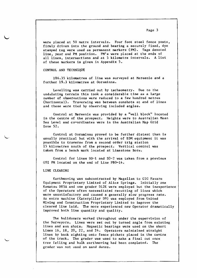

( c (
MEREENIE PROSPECT Appendix 4
GeoEhone SEre ad Vibrator Line Stations Coverage Fo1d Interval Pattern Details Pattern Dates
M82-08 1000-1008 04 2400 50 m A A A 1st January 1982 100S-1060 26 2400 50 m A B A
MS2-0S 1060-1170 55 1200 50 m A B A 1st- 2nd January MS2-10 1000-1090 45 1200 50 m A B A 3rd- 4th January MS2-13 1000-1200 100 1200 50 m A B A 4th- 6th January MS2-15 1014-1290 13S 1200 50 m A B A 6th- 9th January MS2-14 1001-1075 37 1200 50 m A B A 9th January MS2-09 1163-1007 78 1200 50 m A B A 10th-11th January MS2-07 1250-1024 113 1200 50 m A B A 12th-14th January MS2-12 1097-1001 48 1200 50 m A B B 14th-15th January MS2-05 1120- 974 73 1200 50 m A B B 15th-16th January MS2-03 10S2-1002 40 1200 50 m A B B 16th-17th January MS2-01B l1S5-1001 92 1200 50 m A B B 17th-18th January 1-182-20 1169-1001 84 1200 50 m A B B 18th-19th January M82-04 1000-1150 75 1200 50 m A B B 19th-20th January M82-22 1165-1001 82 1200 50 m A B B 21st-22nd January MS2-02 1000-1166 83 1200 50 m A B B 22nd-23rd January MS2-1A 1290-1000 145 1200 50 m A B B 23rd-25th January 1-182-24 1149-1001 74 1200 50 m A B B 27th-28th January M82-11 1510-1004 253 1200 50 m A B B 28th- 1st February M82-6 1006-1180 87 1200 50 m A B B 1st- 2nd February
( c (
Appendix 4 - Page 2
Ge02hone S2read Vibrator Line Stations Coverage Fo1d Interval Pattern Details Pattern Dates
M82-10 1013- 928 425 1200 50 m A B B 2nd- 3rd February Ext M82-16 1000-1086 43 1200 50 m A B B 3rd- 4th February M82-18 1096-1001 475 1200 50 m A B B 4th February
Geophone Pattern
A - 24 x SM4 geophones 2 strings of 12 in series connected in parallel linear over 90 metres 39 metre separation
S2read Details
A = 1400-250-0-250-1400 metres
B = 1300-150-0-150-1300 metres
Vibrator Pattern
A 3 x Y900s 30 metre pad to pad 1 metre moveup centred on peg 16 s~eeps 50-16 Hz16 seconds 75 metres pattern length
( ( (
Appendix 4 - Page 3
B = 3 x Y900s 30 metre pad to pad 1 metre moveup centred on peg 12 sweeps per VP 71 metres pattern length
OORAMINNA PROSPECT
Geo~hone S~read Vibrator Line Stations Covera~ Fold Interval Pattern Details Pattern Dates
01 1004-1100 48 12 50 A A A 8th-10th 02 1000-1l00 50 12 50 A A A 10th-21st 03 1040-1000 20 24 50 A A B 22nd
501 1000-1025 125 24 50 A B B 23rd 502 1000-1125 625 12 50 A A A 23rd-25th
Geophone Pattern
A 24 x SM4 geophones 2 Strings of 12 in series connected in parallel laid in a linear pattern 5 metres separation 115 metres pattern length
S~read Details
B = No gap - whole line live
A = 1400-250-0-250-1400 metres
( ( (
Appendix 4 - Page 4
Vibrator Pattern
A - 3 x Y900 vibrators 14 metres pad to pad 65 metres moveup 1255 metre pattern length centred on peg 16 sweeps 50-16 Hzl6 seconds
B D as A except 325 metre moveup 77 metre pattern length
Appendix 5
MEREENIE PERMANENT MARKER LIST
Peg Descri2tion Elevation Co-ordinates No (m ) E N
Line M-82-1A
1000 SOL 70149 740 171 7 355 749
1020 72258 741 026 7 355 232
1081 PM for INT 730 743 653 7 353 683 1A24
1100 73093 744 472 7 353 201
1144 INT 1A2 73714 746 401 I 1gt2 ObI + 380 m 1200 PM by INT 74075 748 782 7 1)0 667
lA22 1251 PM for INT 75355 750 978 7 349 372
lA4 1270 PM for INT 75910 751 796 7 348 888
lA1B 1290 PM at EOL 76147 752 657 7 348 378
Line M-82-1B
1000 SOL 75425 750 894 7 349 319
1020 PM for INT 75910 751 794 7 348 883 IBIA
1061 PM for INT 75200 753 651 7 347 990 + 11M IB20 1100 77692 755 395 7 347 141
H06 PM for INT 77743 755 691 7 346 996 + 30 1B6 1165 PM for INT 76790 758 315 7 345 716
IB3 H85 EOL 75968 759 214 7 345 276
Line M-82-2
1000 SOL 71512 743 764 7 346 805
1051 PM for INT 74151 744 922 7 349 130 + 48M 211 1066 AT INT GSI 75188 745 241 7 349 756
LINE LGE4A (1981) COMMON P1
-~
Peg No
DescriEtion
Line M-82-2 (Continued)
1100
1117 + 33 1167
PM for INT 21A EOL
Line M-82-3
1002 1020
1038 + 46 1062
SOL PM for INT 3lB and tie to Well WM2 PM for INT 38
PM for INT 35
1082 EOL
Line M-82-4
1000 SOL
1052 INT 411
1100
1108 INT 41A
1150 EOL
Line M-82-6
1006 SOL
1056 + 5M 1090
PM at INT 611
PM beside M-l
1108 + 31M 1159 + 40M 1180
PM at INT
PM at INT
EOL
61B
68
Elevation (m )
73348
73714
75055
77093 76811
75889
74873
73918
72334
75729
75703
75353
75367
74916
75581
78404
77743
75928
75939
Appendix 5 - Page 2
Co-ordinates E N
746 008
746 403
747 490
7 351 274
7 352 066
7 354 279
757 758
589 425
7 345 997 7 345 663
759 299
760 387
761 326
7 345
7 344
7 344
307
920
574
747 927
749 409
750 784
750 955
752 215
7 344 917
7 347 052
7 349 002
7 349 249
7 351 052
753 269
754 447
755 247
755 693
756 917
757 399
7 342 473
7 344 683
7 346 117
7 346 995
7 349 239
7 350 129
-shy
Peg No
Line M-82-5
974
994
1000
1100
1107
1120
Line M-82-7
1023
1041
1067
1100
1149
1200
1231
1250
Line M-82-8
1000
1028 + 2M 1100
1120
1165 + 25 1170
Descrietion
SDL
PM for INT
PM for INT
EDL
SDL
PM for INT
PM for Bend
PM for Bend
PM for INT
EOL
SOL
PM for INT
PM for INT
PM for INT
EDL
53
57
75
79
86
83
810
Elevation (m )
75678
74873
74582
72466
72500
72764
72255
72558
72434
71212
71681
69989
69510
68769
75864
75928
76998
75889
76992
77396
Appendix 5 - Page 3
Co-ordinates E N
759 520 7 345 423
760 384 7 344 920
760 643 7 344 769
764 974 7 342 272
765 280 7 342 102
765 848 7 341 786
764587 7 342 618
765 311 7 342 084
766 357 7 341 312
767 623 7 340 255
769 507 7 338 690
771 618 7 337 257
772 902 7 336 389
773 686 7 335 857
756 182 7 350 434
758 789 7 346 163
759 299 7 345 302
760 458 7 343 344
760 573 7 343 146
~
--_
Peg DescriEtion No
Line M-82-9
1006 SOL
1019 PM at INT 97 + 186 1039 PM at INT 914 +13 1100
1163 EOL
Line M-82-10
928 SOL
1000
1049 PM for INT + 29M 101113 1079 PM for INT + 46t1 108 1090 EOL
Line M-82-11
1005 SOL
1020 PM for INT 111013
1100
1136 PM for INT 116 + 385 1187 PM for INT +11 1120 1200
1248 PM at INT 114 + 8M 1300
1302 PM at INT +11 1122 1347 PM at INT + 8M 1121 1400
Elevation (m )
69631
68728
692 07
66396
73733
77638
76766
76993
76612
77028
76766
75749
75581
75595
75239
75729
76145
75856
74151
70669
Appendix 5 - Page 4
Co-ordinates E N
772 354 7 336 829
772 8735 7 336 407
773 644 7 335 781
775 999 7 333 866
778 453 7 331 891
756 450 7 336 894
758 352 7 339 950
759 661 7 342 055
760 457 7 343 346
760 713 7 343 780
760 324 7 341 708
759 660 7 342 056
756 094 7 343 867
754 448 7 344 682
752 168 7 345 761
751 589 7 346 033
749 412 7 347 053
747 063 7 348 149
746 962 7 348 196
744 921 7 349 133
742 504 7 350 197
Peg No
DescriEtion Elevation (m )
Appendix 5 - Page
Co-ordinates E
5
N
Line M-82-11 (Continued)
1408 PM at INT 1124
1493 INT LllG S1
1500
1510 EDL
L8
70529
69396
69942
742
738
737
737
137
236
916
457
7 350 356
7 352 043
7 352 182
7 352 380
Line M-82-12
1000 SOL
1042 INT 1215 + 41 1046 INT 1213 + 45 1062 BESIDE EM-4 + 34 1068 INT 121
1097 EOL
73408
71415
71232
71093
70037
766 085
767 092
767 188
767 559
767 684
768 379
7 337 241
7 339 130
7 339 310
7 340 006
7 340 240
7 341 512
Line M-82-13
1000 SOL
1020 INT 101113
1100
1169 INT 1315 + 5 1180 INT 1312 + 14 1200 EOL
76569
76766
74057
71434
71239
71508
758 730
759 661
763 407
766 662
767 189
768 124
7 342 418
7 342 053
7 340 654
7 339 497
7 339 312
7 338 998
Line M-82-14
1000 SDL
1029 INT 1415 + 12 1061 INT 149 + 46 1076 EOL
70428
692 15
68723
68300
711 644
772 5861
773 641
774 094
7 333 412
7 334 529
7 335 774
7 336 318
-
-~
Peg Descri)2tion No
Line M-82-15
1014 SOL
1030 PM for INT 1513
1041 INT 1512 + 14 1100
1187 BEND + 23M 1200
1290 EOL
Line M-82-16
1000 SOL
1024 INT 1615
1052 INT 169
1085 EOL
Line M-82-18
1000 SOL
1032 PM for INT 1815
1062 PM for INT 187
1096 EOL
Line M-82-20
1000 SOL
1060 PM for INT 2011
1100
1113 PM for INT + 30M 20IB 1169 EOL
Elevation (m )
72102
71434
71415
71614
69248
69876
69006
70769
68536
69405
677 16
72266
72063
70023
68658
73537
75595
75909
75258
76009
Appendix 5 - Page 6
Co-ordinates N
766 052 7 340 012
766 662 7 339 495
767 092 7 339 130
769 333 7 337 238
772 695 7 334 439
773 219 7 334 089
776 957 7 331 586
774 097 7 332 021
774 864 7 332 932
775 774 7 334 006
776 837 7 335 268
769 832 7 334 715
770 864 7 335 938
771 827 7 337 088
772 920 7 338 390
750 500 7 43 267
752 168 7 345 761
753 276 7 347 421
753 652 7 347 987
755 183 7 350 295
Appendix 5 - Page 7
Peg Descri2tion Elevation Co-ordinates No (m ) E N
Line M-82-22
1000 SOL 72061 745 188 7 345 775
1060 INT 2211 75856 746 963 7 348 193
1100 74102 748 149 7 349 804
1121 INT 221A 74075 748 783 7 350 664 + 18 1165 EOL 75076 758 077 7 352 420
Line M-82-24
1000 SOL 69659 741 038 7 347 888
1054 PM at INT 70529 742 138 7 350 353 2411
1100 73789 743 100 7 352 444
1127 PM at INT 72915 743 639 7 353 679 24lA
1150 EOL 73312 744 092 7 354 735
~ -
OORAMINNA
PERMANENT MARKER LIST
Corrected for SPs 10201025
Peg DescriEtion Elevation No (m)
Line 1
1004 SOL 44189
1090 INT 123 44685
1100 EOL 45003
Line 2
1000 SOL 44906
llOO EOL 45434
Line 3
1000 SOL 44429
1040 EOL 45883
50-1
1000 SOL 50173
1010 + 34
1020
PM for INT SOlS02
50690
1025 EOL 51005
Line 50-2
1000 SOL 50501
1020
1100
PM for INT 501502
50690
50279
1125 EOL 49736
Appendix 5 - Page 8
Co-ordinates E
402 769 7 332 005
402 614 7 332 481
402 458 7 332 956
402 380 7 333 193
401 643 7 332 224
402 600 7 332 513
406 421 7 333 696
407 615 7 334 066
( ( (
~ ~ ~ 6
Diagram Showing Lines at Mereenie Prospect JAN- FEB 1982
fvJ82-1A
2-11 WMl bullM8 ~r-==-~EM~2+7ftrI__J~~ I
M82-15 10 20
J 14 KINGS CANYON
KEY
SEISMiC LINE
bull WELL
x WATER BORE
----- TRACK
FIELD AREA REPORT
CON 179 ENCL No1
( (
Diagram Showing Lines at Ooraminna Prospect FEB 1982
Valley Bore ~ Rd
- 11-gt
bull ~~ bull J~ r Iso~ Atootnenna__~
rEO~ bull
~ore I -- I~~~
--SD2 ~~ SQL ~
~ (P-80-14J 1 ~ SOL Imiddotlt
I -- O---+-- -_ -rffi- t ~~
I_---- ---__- mes one~ Borel ~ I~
KEY _ - shy Tr a (k
~ High Ground
I I
I
Kangar~0 Well ~-=~ ~ ----------MoJNT
MORDRED
FIELD AREA REPORT
CON179 ENCL No2
_ llu _ _ lt~ run~nna )rOnnct3 (ontr1ct 7~)I ror1-~O litin7 tatic om1luta_ ion u~r(w11 ~Md ()
i3itL8L JATB ~2 Wi~ 07 B lflIT
iS 1ST TH gt36 PROMPT l~ u~(L i ~B ilm~ 09 STO fO Ie CUI l LAST qll bull 12 PROIIPT 3 iUn)( 14 AYIEW 15 IlDV 16 STO l I7tlBl 00 I~ SF (l
9 pel BI 28 eLii 21 5TH HO 22 PROIIPT 23 flRCL li 24 I1YIEW 25 STO IND II) 26 XIV 27 CF 89 28 Cll1 29 lt~
38 ARCl X 31 1lIE~
32 2TI) [Hr II
4 12 35 PROHPT 36 I1RCl X 3~ flVIEW 30 ~TO ItUI 12 3) LA 4j IE bull 41 PROIIPT 42 ARCl X 43 flYIEIl 44 ilDY 45 STO INB 13 46 ISI~ Hl 47 ISG II 48 IS( 12 49 ISG J3 58 FC 88 51 eTO 811 S2lBl 81 S3 SF 98 S4 ICl 81 55 ClA 56 STH HO bull 57 PROIIPT S8 I1RCl X 59 IlYIEIi 68 STO HlD 14 61 xlty 62 (f 08 63 ClR 64 DI bull amp5 PPOIIPT 66 flI1Cl X ~~ flYIEIl 69 STO P IS 19 ClA ill f2 bull
I 1n~pr
72 ~(L
73 Am~
~4 AD ~~ ~TO IN]) 16
6 15G 14 77 G 1~
i~ [St 16 7 FC) II) 89 (TO 91 i3I+LBl ~2
B2 SF II~
33 I1CL 91 amp4 (lA 35 STN NO 86 PI10IlPT 87 ARCL x aa I1VIEW 89 STO IHD 17 ~8 )(y
91 CF 98 n ClR 93 ELEV bull 94 PROIIPT lt15 ARCl X AVIEW 97 RDY Iii STO INB IS 99 ISG 17
191) IS 18 Hll Fe 19 i02 GTO 92 183 CUI 194 DATUIt bull 195 PROItPT 136 ARCl X Hl7 AYIEII 198 AIY 199 STO II~ 110 XEIl INIT 111 STH ELEV Dl 12 leI 113 D2 TU 114 IlCR 115 PRBUF 116 ADV 117lBl lHTPl 118 RCl 118 119 RCl IND III 128 XOY 121 RCl IHD III 122 XOV 123 ISG 19 124 RCl lIP III 125 )(=(
126 SF 91 127 Rt 128 shy129 RBH 138 lIOY 131 shy132 Rt 133 I
134 STO 82 135 RCl HiD 11 136 EHTER 137 EHTERt n8 ISG 11 139 ICl IND II 148l10Y 141 shy142 RCl 02 143 44 + 45 STO Pi l41i ~CL INII I 147 EHTE~t
1413 EHint 149 Sl~ 2 ~ peL l
151 X152 - ENCLOSURE 4 153 m 92 1r4 bull 15 156 STO 94 IS7 RCL IN[I 13 1~8 ENTERt 15~ EIITEH 169 1gt( n 161 ~Cl lllII 3 162 xny 163 164 RCl 82 165 166 + 167 TO 85 168 I1CL 811 169 RlL JND 14 170 XOI 171 pel IND 14 172 xm 173 ISG 14 174 RCl 11m 14 175 Xf 176 SF 02 177 Rt 1713 179 I1DN IS8 XOY lSI shy182 Rt 183 I
184 STO 62 HIS I1Cl INB 15 186 EHTERt 187 EHTERt 188 ISG 15 ISCI PCl IHD 15 1ge XOl Ill shy192 PCl 92 193 1~4 + 195 STO tlogt
1 RCl IND IEshy197 EHTERt 198 EHTERt 199 15G 16 296 PCl IND II 2111 XOY
cd RCl 02 284 205 + 286 sro 67 297 RCl 90 288 I(Cl IHB 17 281 XOY 218 RCl INB 17 2I1XOY 212 ISG 17 213 RCl IND 17 214 X=Y 2S SF 83 216 Rt 217 shy218 RUN 219 Xlt)Y 228 shy221 ~t
223 STO 82 224 PC IHD 1~
225 E~TER+
226 EHTHf 227 lSI~ 13 228 Ri IHD 18 229 IV 238shy231 PL ~2
212 bull 2J3 + 234 STO 88 235 FS7C 91 236 GTO 93 237 I 238 ST- 19 239 ST - II 249 5T- 12 241 3T- 13 242tLBL 83 243 FSC 82 244 GTO 94 245 I 246 ST- 14 247 T- IS 248 5T- 16 24qtLBL 94 258 FSC 93 2S1 GTO COPIJTE 252 I 2S3 5T- 17 254 ST- 18 25StLBL COPUTE 256 RCL 90 257 XEQ 97 258 RDN 2~9 ACX 26e bull 261 AeA 2f2 PDH m RCL 89 264 j1CL flS 265 ~CX 266 bull 2(7 ArA 2B 2(~ IItL 85 278 i
271 RCL 96 272 XEQ 95 273 RDH 2(4 ACX 275 bull 276 ilCA 277 flDH 278 PCL 9S 279 IX 289 RCL 93 281 IX 232 shyPl bull 284 +
2l5 ~CL 97 286 XEQ 9S 287 flDH 2SS ACX 239 218 AeR 291 ~PH
292 RCL 95 2ltl3 IX 24 PCL ~4
Plge )]91 XE~ 135 392 RDH 393 P[IN
394 Aex 385 FRBIJF 386 ~CL e~ 397 I
3ij9 TO e~
318 m ~l 311 XCi 312 STOP 313 GTO IHTPL 314tLBL 95 315 EHTERt 316 RHD 317 ~BS 318 III 319 1(=0 329 RTH 321 322 AeR 323 RTN 324tLBL 96 32S EHTERt 326 PHD 327 1119 328 X(=i 329 RTH 339 bull bull 331 ACR 332 11TH 333tLBL 97 334 EHTUt 335 flHD 336 1999 337 X(=(
338 11TH 339 348 IlCR 341 11TH 342tLBL ( HIT 343 FIX 9 344 SF 28 345 CF 29 346 2992991 347 STO 10 348 31l9391H 349 STO II 3S9 4994991 3S1 STO 12 3S2 5995991 3S3 STO 13 354 6996991 355 STO 14 356 7997991 3S7 STO 15 358 899891l1 359 5TO 16 J68 9999991 361 STO 17 362 18919991 363 STO IS 364 PTN 36S EHD
--~ o t q ~J
FIELD AREA REPORTbull~~6
17 -bull CON 119 ENCL No4
2~~ + 2N I E3 3ee
( ( (
Horizontal amp Vertical LOOR Closure Diagram
Mereenie Prospect
1(1 middot
----~~~~~~~v~~~~~~-t~~~~~J~~~~--~~5~7~------_f~~~------~~~8
18 14
~__~~~~_____ 5-3N D~J~~ 9-3D 12087 -0-6 -~-m li -shy - 5
131
12
FIELDAll loops close c1ockwjse AREA REPORT
Not to Sc~ale ENCL No5
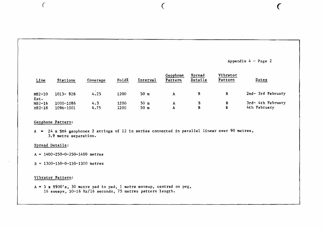
( c (
Appendix 4 - Page 2
Ge02hone S2read Vibrator Line Stations Coverage Fo1d Interval Pattern Details Pattern Dates
M82-10 1013- 928 425 1200 50 m A B B 2nd- 3rd February Ext M82-16 1000-1086 43 1200 50 m A B B 3rd- 4th February M82-18 1096-1001 475 1200 50 m A B B 4th February
Geophone Pattern
A - 24 x SM4 geophones 2 strings of 12 in series connected in parallel linear over 90 metres 39 metre separation
S2read Details
A = 1400-250-0-250-1400 metres
B = 1300-150-0-150-1300 metres
Vibrator Pattern
A 3 x Y900s 30 metre pad to pad 1 metre moveup centred on peg 16 s~eeps 50-16 Hz16 seconds 75 metres pattern length
( ( (
Appendix 4 - Page 3
B = 3 x Y900s 30 metre pad to pad 1 metre moveup centred on peg 12 sweeps per VP 71 metres pattern length
OORAMINNA PROSPECT
Geo~hone S~read Vibrator Line Stations Covera~ Fold Interval Pattern Details Pattern Dates
01 1004-1100 48 12 50 A A A 8th-10th 02 1000-1l00 50 12 50 A A A 10th-21st 03 1040-1000 20 24 50 A A B 22nd
501 1000-1025 125 24 50 A B B 23rd 502 1000-1125 625 12 50 A A A 23rd-25th
Geophone Pattern
A 24 x SM4 geophones 2 Strings of 12 in series connected in parallel laid in a linear pattern 5 metres separation 115 metres pattern length
S~read Details
B = No gap - whole line live
A = 1400-250-0-250-1400 metres
( ( (
Appendix 4 - Page 4
Vibrator Pattern
A - 3 x Y900 vibrators 14 metres pad to pad 65 metres moveup 1255 metre pattern length centred on peg 16 sweeps 50-16 Hzl6 seconds
B D as A except 325 metre moveup 77 metre pattern length
Appendix 5
MEREENIE PERMANENT MARKER LIST
Peg Descri2tion Elevation Co-ordinates No (m ) E N
Line M-82-1A
1000 SOL 70149 740 171 7 355 749
1020 72258 741 026 7 355 232
1081 PM for INT 730 743 653 7 353 683 1A24
1100 73093 744 472 7 353 201
1144 INT 1A2 73714 746 401 I 1gt2 ObI + 380 m 1200 PM by INT 74075 748 782 7 1)0 667
lA22 1251 PM for INT 75355 750 978 7 349 372
lA4 1270 PM for INT 75910 751 796 7 348 888
lA1B 1290 PM at EOL 76147 752 657 7 348 378
Line M-82-1B
1000 SOL 75425 750 894 7 349 319
1020 PM for INT 75910 751 794 7 348 883 IBIA
1061 PM for INT 75200 753 651 7 347 990 + 11M IB20 1100 77692 755 395 7 347 141
H06 PM for INT 77743 755 691 7 346 996 + 30 1B6 1165 PM for INT 76790 758 315 7 345 716
IB3 H85 EOL 75968 759 214 7 345 276
Line M-82-2
1000 SOL 71512 743 764 7 346 805
1051 PM for INT 74151 744 922 7 349 130 + 48M 211 1066 AT INT GSI 75188 745 241 7 349 756
LINE LGE4A (1981) COMMON P1
-~
Peg No
DescriEtion
Line M-82-2 (Continued)
1100
1117 + 33 1167
PM for INT 21A EOL
Line M-82-3
1002 1020
1038 + 46 1062
SOL PM for INT 3lB and tie to Well WM2 PM for INT 38
PM for INT 35
1082 EOL
Line M-82-4
1000 SOL
1052 INT 411
1100
1108 INT 41A
1150 EOL
Line M-82-6
1006 SOL
1056 + 5M 1090
PM at INT 611
PM beside M-l
1108 + 31M 1159 + 40M 1180
PM at INT
PM at INT
EOL
61B
68
Elevation (m )
73348
73714
75055
77093 76811
75889
74873
73918
72334
75729
75703
75353
75367
74916
75581
78404
77743
75928
75939
Appendix 5 - Page 2
Co-ordinates E N
746 008
746 403
747 490
7 351 274
7 352 066
7 354 279
757 758
589 425
7 345 997 7 345 663
759 299
760 387
761 326
7 345
7 344
7 344
307
920
574
747 927
749 409
750 784
750 955
752 215
7 344 917
7 347 052
7 349 002
7 349 249
7 351 052
753 269
754 447
755 247
755 693
756 917
757 399
7 342 473
7 344 683
7 346 117
7 346 995
7 349 239
7 350 129
-shy
Peg No
Line M-82-5
974
994
1000
1100
1107
1120
Line M-82-7
1023
1041
1067
1100
1149
1200
1231
1250
Line M-82-8
1000
1028 + 2M 1100
1120
1165 + 25 1170
Descrietion
SDL
PM for INT
PM for INT
EDL
SDL
PM for INT
PM for Bend
PM for Bend
PM for INT
EOL
SOL
PM for INT
PM for INT
PM for INT
EDL
53
57
75
79
86
83
810
Elevation (m )
75678
74873
74582
72466
72500
72764
72255
72558
72434
71212
71681
69989
69510
68769
75864
75928
76998
75889
76992
77396
Appendix 5 - Page 3
Co-ordinates E N
759 520 7 345 423
760 384 7 344 920
760 643 7 344 769
764 974 7 342 272
765 280 7 342 102
765 848 7 341 786
764587 7 342 618
765 311 7 342 084
766 357 7 341 312
767 623 7 340 255
769 507 7 338 690
771 618 7 337 257
772 902 7 336 389
773 686 7 335 857
756 182 7 350 434
758 789 7 346 163
759 299 7 345 302
760 458 7 343 344
760 573 7 343 146
~
--_
Peg DescriEtion No
Line M-82-9
1006 SOL
1019 PM at INT 97 + 186 1039 PM at INT 914 +13 1100
1163 EOL
Line M-82-10
928 SOL
1000
1049 PM for INT + 29M 101113 1079 PM for INT + 46t1 108 1090 EOL
Line M-82-11
1005 SOL
1020 PM for INT 111013
1100
1136 PM for INT 116 + 385 1187 PM for INT +11 1120 1200
1248 PM at INT 114 + 8M 1300
1302 PM at INT +11 1122 1347 PM at INT + 8M 1121 1400
Elevation (m )
69631
68728
692 07
66396
73733
77638
76766
76993
76612
77028
76766
75749
75581
75595
75239
75729
76145
75856
74151
70669
Appendix 5 - Page 4
Co-ordinates E N
772 354 7 336 829
772 8735 7 336 407
773 644 7 335 781
775 999 7 333 866
778 453 7 331 891
756 450 7 336 894
758 352 7 339 950
759 661 7 342 055
760 457 7 343 346
760 713 7 343 780
760 324 7 341 708
759 660 7 342 056
756 094 7 343 867
754 448 7 344 682
752 168 7 345 761
751 589 7 346 033
749 412 7 347 053
747 063 7 348 149
746 962 7 348 196
744 921 7 349 133
742 504 7 350 197
Peg No
DescriEtion Elevation (m )
Appendix 5 - Page
Co-ordinates E
5
N
Line M-82-11 (Continued)
1408 PM at INT 1124
1493 INT LllG S1
1500
1510 EDL
L8
70529
69396
69942
742
738
737
737
137
236
916
457
7 350 356
7 352 043
7 352 182
7 352 380
Line M-82-12
1000 SOL
1042 INT 1215 + 41 1046 INT 1213 + 45 1062 BESIDE EM-4 + 34 1068 INT 121
1097 EOL
73408
71415
71232
71093
70037
766 085
767 092
767 188
767 559
767 684
768 379
7 337 241
7 339 130
7 339 310
7 340 006
7 340 240
7 341 512
Line M-82-13
1000 SOL
1020 INT 101113
1100
1169 INT 1315 + 5 1180 INT 1312 + 14 1200 EOL
76569
76766
74057
71434
71239
71508
758 730
759 661
763 407
766 662
767 189
768 124
7 342 418
7 342 053
7 340 654
7 339 497
7 339 312
7 338 998
Line M-82-14
1000 SDL
1029 INT 1415 + 12 1061 INT 149 + 46 1076 EOL
70428
692 15
68723
68300
711 644
772 5861
773 641
774 094
7 333 412
7 334 529
7 335 774
7 336 318
-
-~
Peg Descri)2tion No
Line M-82-15
1014 SOL
1030 PM for INT 1513
1041 INT 1512 + 14 1100
1187 BEND + 23M 1200
1290 EOL
Line M-82-16
1000 SOL
1024 INT 1615
1052 INT 169
1085 EOL
Line M-82-18
1000 SOL
1032 PM for INT 1815
1062 PM for INT 187
1096 EOL
Line M-82-20
1000 SOL
1060 PM for INT 2011
1100
1113 PM for INT + 30M 20IB 1169 EOL
Elevation (m )
72102
71434
71415
71614
69248
69876
69006
70769
68536
69405
677 16
72266
72063
70023
68658
73537
75595
75909
75258
76009
Appendix 5 - Page 6
Co-ordinates N
766 052 7 340 012
766 662 7 339 495
767 092 7 339 130
769 333 7 337 238
772 695 7 334 439
773 219 7 334 089
776 957 7 331 586
774 097 7 332 021
774 864 7 332 932
775 774 7 334 006
776 837 7 335 268
769 832 7 334 715
770 864 7 335 938
771 827 7 337 088
772 920 7 338 390
750 500 7 43 267
752 168 7 345 761
753 276 7 347 421
753 652 7 347 987
755 183 7 350 295
Appendix 5 - Page 7
Peg Descri2tion Elevation Co-ordinates No (m ) E N
Line M-82-22
1000 SOL 72061 745 188 7 345 775
1060 INT 2211 75856 746 963 7 348 193
1100 74102 748 149 7 349 804
1121 INT 221A 74075 748 783 7 350 664 + 18 1165 EOL 75076 758 077 7 352 420
Line M-82-24
1000 SOL 69659 741 038 7 347 888
1054 PM at INT 70529 742 138 7 350 353 2411
1100 73789 743 100 7 352 444
1127 PM at INT 72915 743 639 7 353 679 24lA
1150 EOL 73312 744 092 7 354 735
~ -
OORAMINNA
PERMANENT MARKER LIST
Corrected for SPs 10201025
Peg DescriEtion Elevation No (m)
Line 1
1004 SOL 44189
1090 INT 123 44685
1100 EOL 45003
Line 2
1000 SOL 44906
llOO EOL 45434
Line 3
1000 SOL 44429
1040 EOL 45883
50-1
1000 SOL 50173
1010 + 34
1020
PM for INT SOlS02
50690
1025 EOL 51005
Line 50-2
1000 SOL 50501
1020
1100
PM for INT 501502
50690
50279
1125 EOL 49736
Appendix 5 - Page 8
Co-ordinates E
402 769 7 332 005
402 614 7 332 481
402 458 7 332 956
402 380 7 333 193
401 643 7 332 224
402 600 7 332 513
406 421 7 333 696
407 615 7 334 066
( ( (
~ ~ ~ 6
Diagram Showing Lines at Mereenie Prospect JAN- FEB 1982
fvJ82-1A
2-11 WMl bullM8 ~r-==-~EM~2+7ftrI__J~~ I
M82-15 10 20
J 14 KINGS CANYON
KEY
SEISMiC LINE
bull WELL
x WATER BORE
----- TRACK
FIELD AREA REPORT
CON 179 ENCL No1
( (
Diagram Showing Lines at Ooraminna Prospect FEB 1982
Valley Bore ~ Rd
- 11-gt
bull ~~ bull J~ r Iso~ Atootnenna__~
rEO~ bull
~ore I -- I~~~
--SD2 ~~ SQL ~
~ (P-80-14J 1 ~ SOL Imiddotlt
I -- O---+-- -_ -rffi- t ~~
I_---- ---__- mes one~ Borel ~ I~
KEY _ - shy Tr a (k
~ High Ground
I I
I
Kangar~0 Well ~-=~ ~ ----------MoJNT
MORDRED
FIELD AREA REPORT
CON179 ENCL No2
_ llu _ _ lt~ run~nna )rOnnct3 (ontr1ct 7~)I ror1-~O litin7 tatic om1luta_ ion u~r(w11 ~Md ()
i3itL8L JATB ~2 Wi~ 07 B lflIT
iS 1ST TH gt36 PROMPT l~ u~(L i ~B ilm~ 09 STO fO Ie CUI l LAST qll bull 12 PROIIPT 3 iUn)( 14 AYIEW 15 IlDV 16 STO l I7tlBl 00 I~ SF (l
9 pel BI 28 eLii 21 5TH HO 22 PROIIPT 23 flRCL li 24 I1YIEW 25 STO IND II) 26 XIV 27 CF 89 28 Cll1 29 lt~
38 ARCl X 31 1lIE~
32 2TI) [Hr II
4 12 35 PROHPT 36 I1RCl X 3~ flVIEW 30 ~TO ItUI 12 3) LA 4j IE bull 41 PROIIPT 42 ARCl X 43 flYIEIl 44 ilDY 45 STO INB 13 46 ISI~ Hl 47 ISG II 48 IS( 12 49 ISG J3 58 FC 88 51 eTO 811 S2lBl 81 S3 SF 98 S4 ICl 81 55 ClA 56 STH HO bull 57 PROIIPT S8 I1RCl X 59 IlYIEIi 68 STO HlD 14 61 xlty 62 (f 08 63 ClR 64 DI bull amp5 PPOIIPT 66 flI1Cl X ~~ flYIEIl 69 STO P IS 19 ClA ill f2 bull
I 1n~pr
72 ~(L
73 Am~
~4 AD ~~ ~TO IN]) 16
6 15G 14 77 G 1~
i~ [St 16 7 FC) II) 89 (TO 91 i3I+LBl ~2
B2 SF II~
33 I1CL 91 amp4 (lA 35 STN NO 86 PI10IlPT 87 ARCL x aa I1VIEW 89 STO IHD 17 ~8 )(y
91 CF 98 n ClR 93 ELEV bull 94 PROIIPT lt15 ARCl X AVIEW 97 RDY Iii STO INB IS 99 ISG 17
191) IS 18 Hll Fe 19 i02 GTO 92 183 CUI 194 DATUIt bull 195 PROItPT 136 ARCl X Hl7 AYIEII 198 AIY 199 STO II~ 110 XEIl INIT 111 STH ELEV Dl 12 leI 113 D2 TU 114 IlCR 115 PRBUF 116 ADV 117lBl lHTPl 118 RCl 118 119 RCl IND III 128 XOY 121 RCl IHD III 122 XOV 123 ISG 19 124 RCl lIP III 125 )(=(
126 SF 91 127 Rt 128 shy129 RBH 138 lIOY 131 shy132 Rt 133 I
134 STO 82 135 RCl HiD 11 136 EHTER 137 EHTERt n8 ISG 11 139 ICl IND II 148l10Y 141 shy142 RCl 02 143 44 + 45 STO Pi l41i ~CL INII I 147 EHTE~t
1413 EHint 149 Sl~ 2 ~ peL l
151 X152 - ENCLOSURE 4 153 m 92 1r4 bull 15 156 STO 94 IS7 RCL IN[I 13 1~8 ENTERt 15~ EIITEH 169 1gt( n 161 ~Cl lllII 3 162 xny 163 164 RCl 82 165 166 + 167 TO 85 168 I1CL 811 169 RlL JND 14 170 XOI 171 pel IND 14 172 xm 173 ISG 14 174 RCl 11m 14 175 Xf 176 SF 02 177 Rt 1713 179 I1DN IS8 XOY lSI shy182 Rt 183 I
184 STO 62 HIS I1Cl INB 15 186 EHTERt 187 EHTERt 188 ISG 15 ISCI PCl IHD 15 1ge XOl Ill shy192 PCl 92 193 1~4 + 195 STO tlogt
1 RCl IND IEshy197 EHTERt 198 EHTERt 199 15G 16 296 PCl IND II 2111 XOY
cd RCl 02 284 205 + 286 sro 67 297 RCl 90 288 I(Cl IHB 17 281 XOY 218 RCl INB 17 2I1XOY 212 ISG 17 213 RCl IND 17 214 X=Y 2S SF 83 216 Rt 217 shy218 RUN 219 Xlt)Y 228 shy221 ~t
223 STO 82 224 PC IHD 1~
225 E~TER+
226 EHTHf 227 lSI~ 13 228 Ri IHD 18 229 IV 238shy231 PL ~2
212 bull 2J3 + 234 STO 88 235 FS7C 91 236 GTO 93 237 I 238 ST- 19 239 ST - II 249 5T- 12 241 3T- 13 242tLBL 83 243 FSC 82 244 GTO 94 245 I 246 ST- 14 247 T- IS 248 5T- 16 24qtLBL 94 258 FSC 93 2S1 GTO COPIJTE 252 I 2S3 5T- 17 254 ST- 18 25StLBL COPUTE 256 RCL 90 257 XEQ 97 258 RDN 2~9 ACX 26e bull 261 AeA 2f2 PDH m RCL 89 264 j1CL flS 265 ~CX 266 bull 2(7 ArA 2B 2(~ IItL 85 278 i
271 RCL 96 272 XEQ 95 273 RDH 2(4 ACX 275 bull 276 ilCA 277 flDH 278 PCL 9S 279 IX 289 RCL 93 281 IX 232 shyPl bull 284 +
2l5 ~CL 97 286 XEQ 9S 287 flDH 2SS ACX 239 218 AeR 291 ~PH
292 RCL 95 2ltl3 IX 24 PCL ~4
Plge )]91 XE~ 135 392 RDH 393 P[IN
394 Aex 385 FRBIJF 386 ~CL e~ 397 I
3ij9 TO e~
318 m ~l 311 XCi 312 STOP 313 GTO IHTPL 314tLBL 95 315 EHTERt 316 RHD 317 ~BS 318 III 319 1(=0 329 RTH 321 322 AeR 323 RTN 324tLBL 96 32S EHTERt 326 PHD 327 1119 328 X(=i 329 RTH 339 bull bull 331 ACR 332 11TH 333tLBL 97 334 EHTUt 335 flHD 336 1999 337 X(=(
338 11TH 339 348 IlCR 341 11TH 342tLBL ( HIT 343 FIX 9 344 SF 28 345 CF 29 346 2992991 347 STO 10 348 31l9391H 349 STO II 3S9 4994991 3S1 STO 12 3S2 5995991 3S3 STO 13 354 6996991 355 STO 14 356 7997991 3S7 STO 15 358 899891l1 359 5TO 16 J68 9999991 361 STO 17 362 18919991 363 STO IS 364 PTN 36S EHD
--~ o t q ~J
FIELD AREA REPORTbull~~6
17 -bull CON 119 ENCL No4
2~~ + 2N I E3 3ee
( ( (
Horizontal amp Vertical LOOR Closure Diagram
Mereenie Prospect
1(1 middot
----~~~~~~~v~~~~~~-t~~~~~J~~~~--~~5~7~------_f~~~------~~~8
18 14
~__~~~~_____ 5-3N D~J~~ 9-3D 12087 -0-6 -~-m li -shy - 5
131
12
FIELDAll loops close c1ockwjse AREA REPORT
Not to Sc~ale ENCL No5

( ( (
Appendix 4 - Page 4
Vibrator Pattern
A - 3 x Y900 vibrators 14 metres pad to pad 65 metres moveup 1255 metre pattern length centred on peg 16 sweeps 50-16 Hzl6 seconds
B D as A except 325 metre moveup 77 metre pattern length
Appendix 5
MEREENIE PERMANENT MARKER LIST
Peg Descri2tion Elevation Co-ordinates No (m ) E N
Line M-82-1A
1000 SOL 70149 740 171 7 355 749
1020 72258 741 026 7 355 232
1081 PM for INT 730 743 653 7 353 683 1A24
1100 73093 744 472 7 353 201
1144 INT 1A2 73714 746 401 I 1gt2 ObI + 380 m 1200 PM by INT 74075 748 782 7 1)0 667
lA22 1251 PM for INT 75355 750 978 7 349 372
lA4 1270 PM for INT 75910 751 796 7 348 888
lA1B 1290 PM at EOL 76147 752 657 7 348 378
Line M-82-1B
1000 SOL 75425 750 894 7 349 319
1020 PM for INT 75910 751 794 7 348 883 IBIA
1061 PM for INT 75200 753 651 7 347 990 + 11M IB20 1100 77692 755 395 7 347 141
H06 PM for INT 77743 755 691 7 346 996 + 30 1B6 1165 PM for INT 76790 758 315 7 345 716
IB3 H85 EOL 75968 759 214 7 345 276
Line M-82-2
1000 SOL 71512 743 764 7 346 805
1051 PM for INT 74151 744 922 7 349 130 + 48M 211 1066 AT INT GSI 75188 745 241 7 349 756
LINE LGE4A (1981) COMMON P1
-~
Peg No
DescriEtion
Line M-82-2 (Continued)
1100
1117 + 33 1167
PM for INT 21A EOL
Line M-82-3
1002 1020
1038 + 46 1062
SOL PM for INT 3lB and tie to Well WM2 PM for INT 38
PM for INT 35
1082 EOL
Line M-82-4
1000 SOL
1052 INT 411
1100
1108 INT 41A
1150 EOL
Line M-82-6
1006 SOL
1056 + 5M 1090
PM at INT 611
PM beside M-l
1108 + 31M 1159 + 40M 1180
PM at INT
PM at INT
EOL
61B
68
Elevation (m )
73348
73714
75055
77093 76811
75889
74873
73918
72334
75729
75703
75353
75367
74916
75581
78404
77743
75928
75939
Appendix 5 - Page 2
Co-ordinates E N
746 008
746 403
747 490
7 351 274
7 352 066
7 354 279
757 758
589 425
7 345 997 7 345 663
759 299
760 387
761 326
7 345
7 344
7 344
307
920
574
747 927
749 409
750 784
750 955
752 215
7 344 917
7 347 052
7 349 002
7 349 249
7 351 052
753 269
754 447
755 247
755 693
756 917
757 399
7 342 473
7 344 683
7 346 117
7 346 995
7 349 239
7 350 129
-shy
Peg No
Line M-82-5
974
994
1000
1100
1107
1120
Line M-82-7
1023
1041
1067
1100
1149
1200
1231
1250
Line M-82-8
1000
1028 + 2M 1100
1120
1165 + 25 1170
Descrietion
SDL
PM for INT
PM for INT
EDL
SDL
PM for INT
PM for Bend
PM for Bend
PM for INT
EOL
SOL
PM for INT
PM for INT
PM for INT
EDL
53
57
75
79
86
83
810
Elevation (m )
75678
74873
74582
72466
72500
72764
72255
72558
72434
71212
71681
69989
69510
68769
75864
75928
76998
75889
76992
77396
Appendix 5 - Page 3
Co-ordinates E N
759 520 7 345 423
760 384 7 344 920
760 643 7 344 769
764 974 7 342 272
765 280 7 342 102
765 848 7 341 786
764587 7 342 618
765 311 7 342 084
766 357 7 341 312
767 623 7 340 255
769 507 7 338 690
771 618 7 337 257
772 902 7 336 389
773 686 7 335 857
756 182 7 350 434
758 789 7 346 163
759 299 7 345 302
760 458 7 343 344
760 573 7 343 146
~
--_
Peg DescriEtion No
Line M-82-9
1006 SOL
1019 PM at INT 97 + 186 1039 PM at INT 914 +13 1100
1163 EOL
Line M-82-10
928 SOL
1000
1049 PM for INT + 29M 101113 1079 PM for INT + 46t1 108 1090 EOL
Line M-82-11
1005 SOL
1020 PM for INT 111013
1100
1136 PM for INT 116 + 385 1187 PM for INT +11 1120 1200
1248 PM at INT 114 + 8M 1300
1302 PM at INT +11 1122 1347 PM at INT + 8M 1121 1400
Elevation (m )
69631
68728
692 07
66396
73733
77638
76766
76993
76612
77028
76766
75749
75581
75595
75239
75729
76145
75856
74151
70669
Appendix 5 - Page 4
Co-ordinates E N
772 354 7 336 829
772 8735 7 336 407
773 644 7 335 781
775 999 7 333 866
778 453 7 331 891
756 450 7 336 894
758 352 7 339 950
759 661 7 342 055
760 457 7 343 346
760 713 7 343 780
760 324 7 341 708
759 660 7 342 056
756 094 7 343 867
754 448 7 344 682
752 168 7 345 761
751 589 7 346 033
749 412 7 347 053
747 063 7 348 149
746 962 7 348 196
744 921 7 349 133
742 504 7 350 197
Peg No
DescriEtion Elevation (m )
Appendix 5 - Page
Co-ordinates E
5
N
Line M-82-11 (Continued)
1408 PM at INT 1124
1493 INT LllG S1
1500
1510 EDL
L8
70529
69396
69942
742
738
737
737
137
236
916
457
7 350 356
7 352 043
7 352 182
7 352 380
Line M-82-12
1000 SOL
1042 INT 1215 + 41 1046 INT 1213 + 45 1062 BESIDE EM-4 + 34 1068 INT 121
1097 EOL
73408
71415
71232
71093
70037
766 085
767 092
767 188
767 559
767 684
768 379
7 337 241
7 339 130
7 339 310
7 340 006
7 340 240
7 341 512
Line M-82-13
1000 SOL
1020 INT 101113
1100
1169 INT 1315 + 5 1180 INT 1312 + 14 1200 EOL
76569
76766
74057
71434
71239
71508
758 730
759 661
763 407
766 662
767 189
768 124
7 342 418
7 342 053
7 340 654
7 339 497
7 339 312
7 338 998
Line M-82-14
1000 SDL
1029 INT 1415 + 12 1061 INT 149 + 46 1076 EOL
70428
692 15
68723
68300
711 644
772 5861
773 641
774 094
7 333 412
7 334 529
7 335 774
7 336 318
-
-~
Peg Descri)2tion No
Line M-82-15
1014 SOL
1030 PM for INT 1513
1041 INT 1512 + 14 1100
1187 BEND + 23M 1200
1290 EOL
Line M-82-16
1000 SOL
1024 INT 1615
1052 INT 169
1085 EOL
Line M-82-18
1000 SOL
1032 PM for INT 1815
1062 PM for INT 187
1096 EOL
Line M-82-20
1000 SOL
1060 PM for INT 2011
1100
1113 PM for INT + 30M 20IB 1169 EOL
Elevation (m )
72102
71434
71415
71614
69248
69876
69006
70769
68536
69405
677 16
72266
72063
70023
68658
73537
75595
75909
75258
76009
Appendix 5 - Page 6
Co-ordinates N
766 052 7 340 012
766 662 7 339 495
767 092 7 339 130
769 333 7 337 238
772 695 7 334 439
773 219 7 334 089
776 957 7 331 586
774 097 7 332 021
774 864 7 332 932
775 774 7 334 006
776 837 7 335 268
769 832 7 334 715
770 864 7 335 938
771 827 7 337 088
772 920 7 338 390
750 500 7 43 267
752 168 7 345 761
753 276 7 347 421
753 652 7 347 987
755 183 7 350 295
Appendix 5 - Page 7
Peg Descri2tion Elevation Co-ordinates No (m ) E N
Line M-82-22
1000 SOL 72061 745 188 7 345 775
1060 INT 2211 75856 746 963 7 348 193
1100 74102 748 149 7 349 804
1121 INT 221A 74075 748 783 7 350 664 + 18 1165 EOL 75076 758 077 7 352 420
Line M-82-24
1000 SOL 69659 741 038 7 347 888
1054 PM at INT 70529 742 138 7 350 353 2411
1100 73789 743 100 7 352 444
1127 PM at INT 72915 743 639 7 353 679 24lA
1150 EOL 73312 744 092 7 354 735
~ -
OORAMINNA
PERMANENT MARKER LIST
Corrected for SPs 10201025
Peg DescriEtion Elevation No (m)
Line 1
1004 SOL 44189
1090 INT 123 44685
1100 EOL 45003
Line 2
1000 SOL 44906
llOO EOL 45434
Line 3
1000 SOL 44429
1040 EOL 45883
50-1
1000 SOL 50173
1010 + 34
1020
PM for INT SOlS02
50690
1025 EOL 51005
Line 50-2
1000 SOL 50501
1020
1100
PM for INT 501502
50690
50279
1125 EOL 49736
Appendix 5 - Page 8
Co-ordinates E
402 769 7 332 005
402 614 7 332 481
402 458 7 332 956
402 380 7 333 193
401 643 7 332 224
402 600 7 332 513
406 421 7 333 696
407 615 7 334 066
( ( (
~ ~ ~ 6
Diagram Showing Lines at Mereenie Prospect JAN- FEB 1982
fvJ82-1A
2-11 WMl bullM8 ~r-==-~EM~2+7ftrI__J~~ I
M82-15 10 20
J 14 KINGS CANYON
KEY
SEISMiC LINE
bull WELL
x WATER BORE
----- TRACK
FIELD AREA REPORT
CON 179 ENCL No1
( (
Diagram Showing Lines at Ooraminna Prospect FEB 1982
Valley Bore ~ Rd
- 11-gt
bull ~~ bull J~ r Iso~ Atootnenna__~
rEO~ bull
~ore I -- I~~~
--SD2 ~~ SQL ~
~ (P-80-14J 1 ~ SOL Imiddotlt
I -- O---+-- -_ -rffi- t ~~
I_---- ---__- mes one~ Borel ~ I~
KEY _ - shy Tr a (k
~ High Ground
I I
I
Kangar~0 Well ~-=~ ~ ----------MoJNT
MORDRED
FIELD AREA REPORT
CON179 ENCL No2
_ llu _ _ lt~ run~nna )rOnnct3 (ontr1ct 7~)I ror1-~O litin7 tatic om1luta_ ion u~r(w11 ~Md ()
i3itL8L JATB ~2 Wi~ 07 B lflIT
iS 1ST TH gt36 PROMPT l~ u~(L i ~B ilm~ 09 STO fO Ie CUI l LAST qll bull 12 PROIIPT 3 iUn)( 14 AYIEW 15 IlDV 16 STO l I7tlBl 00 I~ SF (l
9 pel BI 28 eLii 21 5TH HO 22 PROIIPT 23 flRCL li 24 I1YIEW 25 STO IND II) 26 XIV 27 CF 89 28 Cll1 29 lt~
38 ARCl X 31 1lIE~
32 2TI) [Hr II
4 12 35 PROHPT 36 I1RCl X 3~ flVIEW 30 ~TO ItUI 12 3) LA 4j IE bull 41 PROIIPT 42 ARCl X 43 flYIEIl 44 ilDY 45 STO INB 13 46 ISI~ Hl 47 ISG II 48 IS( 12 49 ISG J3 58 FC 88 51 eTO 811 S2lBl 81 S3 SF 98 S4 ICl 81 55 ClA 56 STH HO bull 57 PROIIPT S8 I1RCl X 59 IlYIEIi 68 STO HlD 14 61 xlty 62 (f 08 63 ClR 64 DI bull amp5 PPOIIPT 66 flI1Cl X ~~ flYIEIl 69 STO P IS 19 ClA ill f2 bull
I 1n~pr
72 ~(L
73 Am~
~4 AD ~~ ~TO IN]) 16
6 15G 14 77 G 1~
i~ [St 16 7 FC) II) 89 (TO 91 i3I+LBl ~2
B2 SF II~
33 I1CL 91 amp4 (lA 35 STN NO 86 PI10IlPT 87 ARCL x aa I1VIEW 89 STO IHD 17 ~8 )(y
91 CF 98 n ClR 93 ELEV bull 94 PROIIPT lt15 ARCl X AVIEW 97 RDY Iii STO INB IS 99 ISG 17
191) IS 18 Hll Fe 19 i02 GTO 92 183 CUI 194 DATUIt bull 195 PROItPT 136 ARCl X Hl7 AYIEII 198 AIY 199 STO II~ 110 XEIl INIT 111 STH ELEV Dl 12 leI 113 D2 TU 114 IlCR 115 PRBUF 116 ADV 117lBl lHTPl 118 RCl 118 119 RCl IND III 128 XOY 121 RCl IHD III 122 XOV 123 ISG 19 124 RCl lIP III 125 )(=(
126 SF 91 127 Rt 128 shy129 RBH 138 lIOY 131 shy132 Rt 133 I
134 STO 82 135 RCl HiD 11 136 EHTER 137 EHTERt n8 ISG 11 139 ICl IND II 148l10Y 141 shy142 RCl 02 143 44 + 45 STO Pi l41i ~CL INII I 147 EHTE~t
1413 EHint 149 Sl~ 2 ~ peL l
151 X152 - ENCLOSURE 4 153 m 92 1r4 bull 15 156 STO 94 IS7 RCL IN[I 13 1~8 ENTERt 15~ EIITEH 169 1gt( n 161 ~Cl lllII 3 162 xny 163 164 RCl 82 165 166 + 167 TO 85 168 I1CL 811 169 RlL JND 14 170 XOI 171 pel IND 14 172 xm 173 ISG 14 174 RCl 11m 14 175 Xf 176 SF 02 177 Rt 1713 179 I1DN IS8 XOY lSI shy182 Rt 183 I
184 STO 62 HIS I1Cl INB 15 186 EHTERt 187 EHTERt 188 ISG 15 ISCI PCl IHD 15 1ge XOl Ill shy192 PCl 92 193 1~4 + 195 STO tlogt
1 RCl IND IEshy197 EHTERt 198 EHTERt 199 15G 16 296 PCl IND II 2111 XOY
cd RCl 02 284 205 + 286 sro 67 297 RCl 90 288 I(Cl IHB 17 281 XOY 218 RCl INB 17 2I1XOY 212 ISG 17 213 RCl IND 17 214 X=Y 2S SF 83 216 Rt 217 shy218 RUN 219 Xlt)Y 228 shy221 ~t
223 STO 82 224 PC IHD 1~
225 E~TER+
226 EHTHf 227 lSI~ 13 228 Ri IHD 18 229 IV 238shy231 PL ~2
212 bull 2J3 + 234 STO 88 235 FS7C 91 236 GTO 93 237 I 238 ST- 19 239 ST - II 249 5T- 12 241 3T- 13 242tLBL 83 243 FSC 82 244 GTO 94 245 I 246 ST- 14 247 T- IS 248 5T- 16 24qtLBL 94 258 FSC 93 2S1 GTO COPIJTE 252 I 2S3 5T- 17 254 ST- 18 25StLBL COPUTE 256 RCL 90 257 XEQ 97 258 RDN 2~9 ACX 26e bull 261 AeA 2f2 PDH m RCL 89 264 j1CL flS 265 ~CX 266 bull 2(7 ArA 2B 2(~ IItL 85 278 i
271 RCL 96 272 XEQ 95 273 RDH 2(4 ACX 275 bull 276 ilCA 277 flDH 278 PCL 9S 279 IX 289 RCL 93 281 IX 232 shyPl bull 284 +
2l5 ~CL 97 286 XEQ 9S 287 flDH 2SS ACX 239 218 AeR 291 ~PH
292 RCL 95 2ltl3 IX 24 PCL ~4
Plge )]91 XE~ 135 392 RDH 393 P[IN
394 Aex 385 FRBIJF 386 ~CL e~ 397 I
3ij9 TO e~
318 m ~l 311 XCi 312 STOP 313 GTO IHTPL 314tLBL 95 315 EHTERt 316 RHD 317 ~BS 318 III 319 1(=0 329 RTH 321 322 AeR 323 RTN 324tLBL 96 32S EHTERt 326 PHD 327 1119 328 X(=i 329 RTH 339 bull bull 331 ACR 332 11TH 333tLBL 97 334 EHTUt 335 flHD 336 1999 337 X(=(
338 11TH 339 348 IlCR 341 11TH 342tLBL ( HIT 343 FIX 9 344 SF 28 345 CF 29 346 2992991 347 STO 10 348 31l9391H 349 STO II 3S9 4994991 3S1 STO 12 3S2 5995991 3S3 STO 13 354 6996991 355 STO 14 356 7997991 3S7 STO 15 358 899891l1 359 5TO 16 J68 9999991 361 STO 17 362 18919991 363 STO IS 364 PTN 36S EHD
--~ o t q ~J
FIELD AREA REPORTbull~~6
17 -bull CON 119 ENCL No4
2~~ + 2N I E3 3ee
( ( (
Horizontal amp Vertical LOOR Closure Diagram
Mereenie Prospect
1(1 middot
----~~~~~~~v~~~~~~-t~~~~~J~~~~--~~5~7~------_f~~~------~~~8
18 14
~__~~~~_____ 5-3N D~J~~ 9-3D 12087 -0-6 -~-m li -shy - 5
131
12
FIELDAll loops close c1ockwjse AREA REPORT
Not to Sc~ale ENCL No5

-~
Peg No
DescriEtion
Line M-82-2 (Continued)
1100
1117 + 33 1167
PM for INT 21A EOL
Line M-82-3
1002 1020
1038 + 46 1062
SOL PM for INT 3lB and tie to Well WM2 PM for INT 38
PM for INT 35
1082 EOL
Line M-82-4
1000 SOL
1052 INT 411
1100
1108 INT 41A
1150 EOL
Line M-82-6
1006 SOL
1056 + 5M 1090
PM at INT 611
PM beside M-l
1108 + 31M 1159 + 40M 1180
PM at INT
PM at INT
EOL
61B
68
Elevation (m )
73348
73714
75055
77093 76811
75889
74873
73918
72334
75729
75703
75353
75367
74916
75581
78404
77743
75928
75939
Appendix 5 - Page 2
Co-ordinates E N
746 008
746 403
747 490
7 351 274
7 352 066
7 354 279
757 758
589 425
7 345 997 7 345 663
759 299
760 387
761 326
7 345
7 344
7 344
307
920
574
747 927
749 409
750 784
750 955
752 215
7 344 917
7 347 052
7 349 002
7 349 249
7 351 052
753 269
754 447
755 247
755 693
756 917
757 399
7 342 473
7 344 683
7 346 117
7 346 995
7 349 239
7 350 129
-shy
Peg No
Line M-82-5
974
994
1000
1100
1107
1120
Line M-82-7
1023
1041
1067
1100
1149
1200
1231
1250
Line M-82-8
1000
1028 + 2M 1100
1120
1165 + 25 1170
Descrietion
SDL
PM for INT
PM for INT
EDL
SDL
PM for INT
PM for Bend
PM for Bend
PM for INT
EOL
SOL
PM for INT
PM for INT
PM for INT
EDL
53
57
75
79
86
83
810
Elevation (m )
75678
74873
74582
72466
72500
72764
72255
72558
72434
71212
71681
69989
69510
68769
75864
75928
76998
75889
76992
77396
Appendix 5 - Page 3
Co-ordinates E N
759 520 7 345 423
760 384 7 344 920
760 643 7 344 769
764 974 7 342 272
765 280 7 342 102
765 848 7 341 786
764587 7 342 618
765 311 7 342 084
766 357 7 341 312
767 623 7 340 255
769 507 7 338 690
771 618 7 337 257
772 902 7 336 389
773 686 7 335 857
756 182 7 350 434
758 789 7 346 163
759 299 7 345 302
760 458 7 343 344
760 573 7 343 146
~
--_
Peg DescriEtion No
Line M-82-9
1006 SOL
1019 PM at INT 97 + 186 1039 PM at INT 914 +13 1100
1163 EOL
Line M-82-10
928 SOL
1000
1049 PM for INT + 29M 101113 1079 PM for INT + 46t1 108 1090 EOL
Line M-82-11
1005 SOL
1020 PM for INT 111013
1100
1136 PM for INT 116 + 385 1187 PM for INT +11 1120 1200
1248 PM at INT 114 + 8M 1300
1302 PM at INT +11 1122 1347 PM at INT + 8M 1121 1400
Elevation (m )
69631
68728
692 07
66396
73733
77638
76766
76993
76612
77028
76766
75749
75581
75595
75239
75729
76145
75856
74151
70669
Appendix 5 - Page 4
Co-ordinates E N
772 354 7 336 829
772 8735 7 336 407
773 644 7 335 781
775 999 7 333 866
778 453 7 331 891
756 450 7 336 894
758 352 7 339 950
759 661 7 342 055
760 457 7 343 346
760 713 7 343 780
760 324 7 341 708
759 660 7 342 056
756 094 7 343 867
754 448 7 344 682
752 168 7 345 761
751 589 7 346 033
749 412 7 347 053
747 063 7 348 149
746 962 7 348 196
744 921 7 349 133
742 504 7 350 197
Peg No
DescriEtion Elevation (m )
Appendix 5 - Page
Co-ordinates E
5
N
Line M-82-11 (Continued)
1408 PM at INT 1124
1493 INT LllG S1
1500
1510 EDL
L8
70529
69396
69942
742
738
737
737
137
236
916
457
7 350 356
7 352 043
7 352 182
7 352 380
Line M-82-12
1000 SOL
1042 INT 1215 + 41 1046 INT 1213 + 45 1062 BESIDE EM-4 + 34 1068 INT 121
1097 EOL
73408
71415
71232
71093
70037
766 085
767 092
767 188
767 559
767 684
768 379
7 337 241
7 339 130
7 339 310
7 340 006
7 340 240
7 341 512
Line M-82-13
1000 SOL
1020 INT 101113
1100
1169 INT 1315 + 5 1180 INT 1312 + 14 1200 EOL
76569
76766
74057
71434
71239
71508
758 730
759 661
763 407
766 662
767 189
768 124
7 342 418
7 342 053
7 340 654
7 339 497
7 339 312
7 338 998
Line M-82-14
1000 SDL
1029 INT 1415 + 12 1061 INT 149 + 46 1076 EOL
70428
692 15
68723
68300
711 644
772 5861
773 641
774 094
7 333 412
7 334 529
7 335 774
7 336 318
-
-~
Peg Descri)2tion No
Line M-82-15
1014 SOL
1030 PM for INT 1513
1041 INT 1512 + 14 1100
1187 BEND + 23M 1200
1290 EOL
Line M-82-16
1000 SOL
1024 INT 1615
1052 INT 169
1085 EOL
Line M-82-18
1000 SOL
1032 PM for INT 1815
1062 PM for INT 187
1096 EOL
Line M-82-20
1000 SOL
1060 PM for INT 2011
1100
1113 PM for INT + 30M 20IB 1169 EOL
Elevation (m )
72102
71434
71415
71614
69248
69876
69006
70769
68536
69405
677 16
72266
72063
70023
68658
73537
75595
75909
75258
76009
Appendix 5 - Page 6
Co-ordinates N
766 052 7 340 012
766 662 7 339 495
767 092 7 339 130
769 333 7 337 238
772 695 7 334 439
773 219 7 334 089
776 957 7 331 586
774 097 7 332 021
774 864 7 332 932
775 774 7 334 006
776 837 7 335 268
769 832 7 334 715
770 864 7 335 938
771 827 7 337 088
772 920 7 338 390
750 500 7 43 267
752 168 7 345 761
753 276 7 347 421
753 652 7 347 987
755 183 7 350 295
Appendix 5 - Page 7
Peg Descri2tion Elevation Co-ordinates No (m ) E N
Line M-82-22
1000 SOL 72061 745 188 7 345 775
1060 INT 2211 75856 746 963 7 348 193
1100 74102 748 149 7 349 804
1121 INT 221A 74075 748 783 7 350 664 + 18 1165 EOL 75076 758 077 7 352 420
Line M-82-24
1000 SOL 69659 741 038 7 347 888
1054 PM at INT 70529 742 138 7 350 353 2411
1100 73789 743 100 7 352 444
1127 PM at INT 72915 743 639 7 353 679 24lA
1150 EOL 73312 744 092 7 354 735
~ -
OORAMINNA
PERMANENT MARKER LIST
Corrected for SPs 10201025
Peg DescriEtion Elevation No (m)
Line 1
1004 SOL 44189
1090 INT 123 44685
1100 EOL 45003
Line 2
1000 SOL 44906
llOO EOL 45434
Line 3
1000 SOL 44429
1040 EOL 45883
50-1
1000 SOL 50173
1010 + 34
1020
PM for INT SOlS02
50690
1025 EOL 51005
Line 50-2
1000 SOL 50501
1020
1100
PM for INT 501502
50690
50279
1125 EOL 49736
Appendix 5 - Page 8
Co-ordinates E
402 769 7 332 005
402 614 7 332 481
402 458 7 332 956
402 380 7 333 193
401 643 7 332 224
402 600 7 332 513
406 421 7 333 696
407 615 7 334 066
( ( (
~ ~ ~ 6
Diagram Showing Lines at Mereenie Prospect JAN- FEB 1982
fvJ82-1A
2-11 WMl bullM8 ~r-==-~EM~2+7ftrI__J~~ I
M82-15 10 20
J 14 KINGS CANYON
KEY
SEISMiC LINE
bull WELL
x WATER BORE
----- TRACK
FIELD AREA REPORT
CON 179 ENCL No1
( (
Diagram Showing Lines at Ooraminna Prospect FEB 1982
Valley Bore ~ Rd
- 11-gt
bull ~~ bull J~ r Iso~ Atootnenna__~
rEO~ bull
~ore I -- I~~~
--SD2 ~~ SQL ~
~ (P-80-14J 1 ~ SOL Imiddotlt
I -- O---+-- -_ -rffi- t ~~
I_---- ---__- mes one~ Borel ~ I~
KEY _ - shy Tr a (k
~ High Ground
I I
I
Kangar~0 Well ~-=~ ~ ----------MoJNT
MORDRED
FIELD AREA REPORT
CON179 ENCL No2
_ llu _ _ lt~ run~nna )rOnnct3 (ontr1ct 7~)I ror1-~O litin7 tatic om1luta_ ion u~r(w11 ~Md ()
i3itL8L JATB ~2 Wi~ 07 B lflIT
iS 1ST TH gt36 PROMPT l~ u~(L i ~B ilm~ 09 STO fO Ie CUI l LAST qll bull 12 PROIIPT 3 iUn)( 14 AYIEW 15 IlDV 16 STO l I7tlBl 00 I~ SF (l
9 pel BI 28 eLii 21 5TH HO 22 PROIIPT 23 flRCL li 24 I1YIEW 25 STO IND II) 26 XIV 27 CF 89 28 Cll1 29 lt~
38 ARCl X 31 1lIE~
32 2TI) [Hr II
4 12 35 PROHPT 36 I1RCl X 3~ flVIEW 30 ~TO ItUI 12 3) LA 4j IE bull 41 PROIIPT 42 ARCl X 43 flYIEIl 44 ilDY 45 STO INB 13 46 ISI~ Hl 47 ISG II 48 IS( 12 49 ISG J3 58 FC 88 51 eTO 811 S2lBl 81 S3 SF 98 S4 ICl 81 55 ClA 56 STH HO bull 57 PROIIPT S8 I1RCl X 59 IlYIEIi 68 STO HlD 14 61 xlty 62 (f 08 63 ClR 64 DI bull amp5 PPOIIPT 66 flI1Cl X ~~ flYIEIl 69 STO P IS 19 ClA ill f2 bull
I 1n~pr
72 ~(L
73 Am~
~4 AD ~~ ~TO IN]) 16
6 15G 14 77 G 1~
i~ [St 16 7 FC) II) 89 (TO 91 i3I+LBl ~2
B2 SF II~
33 I1CL 91 amp4 (lA 35 STN NO 86 PI10IlPT 87 ARCL x aa I1VIEW 89 STO IHD 17 ~8 )(y
91 CF 98 n ClR 93 ELEV bull 94 PROIIPT lt15 ARCl X AVIEW 97 RDY Iii STO INB IS 99 ISG 17
191) IS 18 Hll Fe 19 i02 GTO 92 183 CUI 194 DATUIt bull 195 PROItPT 136 ARCl X Hl7 AYIEII 198 AIY 199 STO II~ 110 XEIl INIT 111 STH ELEV Dl 12 leI 113 D2 TU 114 IlCR 115 PRBUF 116 ADV 117lBl lHTPl 118 RCl 118 119 RCl IND III 128 XOY 121 RCl IHD III 122 XOV 123 ISG 19 124 RCl lIP III 125 )(=(
126 SF 91 127 Rt 128 shy129 RBH 138 lIOY 131 shy132 Rt 133 I
134 STO 82 135 RCl HiD 11 136 EHTER 137 EHTERt n8 ISG 11 139 ICl IND II 148l10Y 141 shy142 RCl 02 143 44 + 45 STO Pi l41i ~CL INII I 147 EHTE~t
1413 EHint 149 Sl~ 2 ~ peL l
151 X152 - ENCLOSURE 4 153 m 92 1r4 bull 15 156 STO 94 IS7 RCL IN[I 13 1~8 ENTERt 15~ EIITEH 169 1gt( n 161 ~Cl lllII 3 162 xny 163 164 RCl 82 165 166 + 167 TO 85 168 I1CL 811 169 RlL JND 14 170 XOI 171 pel IND 14 172 xm 173 ISG 14 174 RCl 11m 14 175 Xf 176 SF 02 177 Rt 1713 179 I1DN IS8 XOY lSI shy182 Rt 183 I
184 STO 62 HIS I1Cl INB 15 186 EHTERt 187 EHTERt 188 ISG 15 ISCI PCl IHD 15 1ge XOl Ill shy192 PCl 92 193 1~4 + 195 STO tlogt
1 RCl IND IEshy197 EHTERt 198 EHTERt 199 15G 16 296 PCl IND II 2111 XOY
cd RCl 02 284 205 + 286 sro 67 297 RCl 90 288 I(Cl IHB 17 281 XOY 218 RCl INB 17 2I1XOY 212 ISG 17 213 RCl IND 17 214 X=Y 2S SF 83 216 Rt 217 shy218 RUN 219 Xlt)Y 228 shy221 ~t
223 STO 82 224 PC IHD 1~
225 E~TER+
226 EHTHf 227 lSI~ 13 228 Ri IHD 18 229 IV 238shy231 PL ~2
212 bull 2J3 + 234 STO 88 235 FS7C 91 236 GTO 93 237 I 238 ST- 19 239 ST - II 249 5T- 12 241 3T- 13 242tLBL 83 243 FSC 82 244 GTO 94 245 I 246 ST- 14 247 T- IS 248 5T- 16 24qtLBL 94 258 FSC 93 2S1 GTO COPIJTE 252 I 2S3 5T- 17 254 ST- 18 25StLBL COPUTE 256 RCL 90 257 XEQ 97 258 RDN 2~9 ACX 26e bull 261 AeA 2f2 PDH m RCL 89 264 j1CL flS 265 ~CX 266 bull 2(7 ArA 2B 2(~ IItL 85 278 i
271 RCL 96 272 XEQ 95 273 RDH 2(4 ACX 275 bull 276 ilCA 277 flDH 278 PCL 9S 279 IX 289 RCL 93 281 IX 232 shyPl bull 284 +
2l5 ~CL 97 286 XEQ 9S 287 flDH 2SS ACX 239 218 AeR 291 ~PH
292 RCL 95 2ltl3 IX 24 PCL ~4
Plge )]91 XE~ 135 392 RDH 393 P[IN
394 Aex 385 FRBIJF 386 ~CL e~ 397 I
3ij9 TO e~
318 m ~l 311 XCi 312 STOP 313 GTO IHTPL 314tLBL 95 315 EHTERt 316 RHD 317 ~BS 318 III 319 1(=0 329 RTH 321 322 AeR 323 RTN 324tLBL 96 32S EHTERt 326 PHD 327 1119 328 X(=i 329 RTH 339 bull bull 331 ACR 332 11TH 333tLBL 97 334 EHTUt 335 flHD 336 1999 337 X(=(
338 11TH 339 348 IlCR 341 11TH 342tLBL ( HIT 343 FIX 9 344 SF 28 345 CF 29 346 2992991 347 STO 10 348 31l9391H 349 STO II 3S9 4994991 3S1 STO 12 3S2 5995991 3S3 STO 13 354 6996991 355 STO 14 356 7997991 3S7 STO 15 358 899891l1 359 5TO 16 J68 9999991 361 STO 17 362 18919991 363 STO IS 364 PTN 36S EHD
--~ o t q ~J
FIELD AREA REPORTbull~~6
17 -bull CON 119 ENCL No4
2~~ + 2N I E3 3ee
( ( (
Horizontal amp Vertical LOOR Closure Diagram
Mereenie Prospect
1(1 middot
----~~~~~~~v~~~~~~-t~~~~~J~~~~--~~5~7~------_f~~~------~~~8
18 14
~__~~~~_____ 5-3N D~J~~ 9-3D 12087 -0-6 -~-m li -shy - 5
131
12
FIELDAll loops close c1ockwjse AREA REPORT
Not to Sc~ale ENCL No5

( ( (
~ ~ ~ 6
Diagram Showing Lines at Mereenie Prospect JAN- FEB 1982
fvJ82-1A
2-11 WMl bullM8 ~r-==-~EM~2+7ftrI__J~~ I
M82-15 10 20
J 14 KINGS CANYON
KEY
SEISMiC LINE
bull WELL
x WATER BORE
----- TRACK
FIELD AREA REPORT
CON 179 ENCL No1
( (
Diagram Showing Lines at Ooraminna Prospect FEB 1982
Valley Bore ~ Rd
- 11-gt
bull ~~ bull J~ r Iso~ Atootnenna__~
rEO~ bull
~ore I -- I~~~
--SD2 ~~ SQL ~
~ (P-80-14J 1 ~ SOL Imiddotlt
I -- O---+-- -_ -rffi- t ~~
I_---- ---__- mes one~ Borel ~ I~
KEY _ - shy Tr a (k
~ High Ground
I I
I
Kangar~0 Well ~-=~ ~ ----------MoJNT
MORDRED
FIELD AREA REPORT
CON179 ENCL No2
_ llu _ _ lt~ run~nna )rOnnct3 (ontr1ct 7~)I ror1-~O litin7 tatic om1luta_ ion u~r(w11 ~Md ()
i3itL8L JATB ~2 Wi~ 07 B lflIT
iS 1ST TH gt36 PROMPT l~ u~(L i ~B ilm~ 09 STO fO Ie CUI l LAST qll bull 12 PROIIPT 3 iUn)( 14 AYIEW 15 IlDV 16 STO l I7tlBl 00 I~ SF (l
9 pel BI 28 eLii 21 5TH HO 22 PROIIPT 23 flRCL li 24 I1YIEW 25 STO IND II) 26 XIV 27 CF 89 28 Cll1 29 lt~
38 ARCl X 31 1lIE~
32 2TI) [Hr II
4 12 35 PROHPT 36 I1RCl X 3~ flVIEW 30 ~TO ItUI 12 3) LA 4j IE bull 41 PROIIPT 42 ARCl X 43 flYIEIl 44 ilDY 45 STO INB 13 46 ISI~ Hl 47 ISG II 48 IS( 12 49 ISG J3 58 FC 88 51 eTO 811 S2lBl 81 S3 SF 98 S4 ICl 81 55 ClA 56 STH HO bull 57 PROIIPT S8 I1RCl X 59 IlYIEIi 68 STO HlD 14 61 xlty 62 (f 08 63 ClR 64 DI bull amp5 PPOIIPT 66 flI1Cl X ~~ flYIEIl 69 STO P IS 19 ClA ill f2 bull
I 1n~pr
72 ~(L
73 Am~
~4 AD ~~ ~TO IN]) 16
6 15G 14 77 G 1~
i~ [St 16 7 FC) II) 89 (TO 91 i3I+LBl ~2
B2 SF II~
33 I1CL 91 amp4 (lA 35 STN NO 86 PI10IlPT 87 ARCL x aa I1VIEW 89 STO IHD 17 ~8 )(y
91 CF 98 n ClR 93 ELEV bull 94 PROIIPT lt15 ARCl X AVIEW 97 RDY Iii STO INB IS 99 ISG 17
191) IS 18 Hll Fe 19 i02 GTO 92 183 CUI 194 DATUIt bull 195 PROItPT 136 ARCl X Hl7 AYIEII 198 AIY 199 STO II~ 110 XEIl INIT 111 STH ELEV Dl 12 leI 113 D2 TU 114 IlCR 115 PRBUF 116 ADV 117lBl lHTPl 118 RCl 118 119 RCl IND III 128 XOY 121 RCl IHD III 122 XOV 123 ISG 19 124 RCl lIP III 125 )(=(
126 SF 91 127 Rt 128 shy129 RBH 138 lIOY 131 shy132 Rt 133 I
134 STO 82 135 RCl HiD 11 136 EHTER 137 EHTERt n8 ISG 11 139 ICl IND II 148l10Y 141 shy142 RCl 02 143 44 + 45 STO Pi l41i ~CL INII I 147 EHTE~t
1413 EHint 149 Sl~ 2 ~ peL l
151 X152 - ENCLOSURE 4 153 m 92 1r4 bull 15 156 STO 94 IS7 RCL IN[I 13 1~8 ENTERt 15~ EIITEH 169 1gt( n 161 ~Cl lllII 3 162 xny 163 164 RCl 82 165 166 + 167 TO 85 168 I1CL 811 169 RlL JND 14 170 XOI 171 pel IND 14 172 xm 173 ISG 14 174 RCl 11m 14 175 Xf 176 SF 02 177 Rt 1713 179 I1DN IS8 XOY lSI shy182 Rt 183 I
184 STO 62 HIS I1Cl INB 15 186 EHTERt 187 EHTERt 188 ISG 15 ISCI PCl IHD 15 1ge XOl Ill shy192 PCl 92 193 1~4 + 195 STO tlogt
1 RCl IND IEshy197 EHTERt 198 EHTERt 199 15G 16 296 PCl IND II 2111 XOY
cd RCl 02 284 205 + 286 sro 67 297 RCl 90 288 I(Cl IHB 17 281 XOY 218 RCl INB 17 2I1XOY 212 ISG 17 213 RCl IND 17 214 X=Y 2S SF 83 216 Rt 217 shy218 RUN 219 Xlt)Y 228 shy221 ~t
223 STO 82 224 PC IHD 1~
225 E~TER+
226 EHTHf 227 lSI~ 13 228 Ri IHD 18 229 IV 238shy231 PL ~2
212 bull 2J3 + 234 STO 88 235 FS7C 91 236 GTO 93 237 I 238 ST- 19 239 ST - II 249 5T- 12 241 3T- 13 242tLBL 83 243 FSC 82 244 GTO 94 245 I 246 ST- 14 247 T- IS 248 5T- 16 24qtLBL 94 258 FSC 93 2S1 GTO COPIJTE 252 I 2S3 5T- 17 254 ST- 18 25StLBL COPUTE 256 RCL 90 257 XEQ 97 258 RDN 2~9 ACX 26e bull 261 AeA 2f2 PDH m RCL 89 264 j1CL flS 265 ~CX 266 bull 2(7 ArA 2B 2(~ IItL 85 278 i
271 RCL 96 272 XEQ 95 273 RDH 2(4 ACX 275 bull 276 ilCA 277 flDH 278 PCL 9S 279 IX 289 RCL 93 281 IX 232 shyPl bull 284 +
2l5 ~CL 97 286 XEQ 9S 287 flDH 2SS ACX 239 218 AeR 291 ~PH
292 RCL 95 2ltl3 IX 24 PCL ~4
Plge )]91 XE~ 135 392 RDH 393 P[IN
394 Aex 385 FRBIJF 386 ~CL e~ 397 I
3ij9 TO e~
318 m ~l 311 XCi 312 STOP 313 GTO IHTPL 314tLBL 95 315 EHTERt 316 RHD 317 ~BS 318 III 319 1(=0 329 RTH 321 322 AeR 323 RTN 324tLBL 96 32S EHTERt 326 PHD 327 1119 328 X(=i 329 RTH 339 bull bull 331 ACR 332 11TH 333tLBL 97 334 EHTUt 335 flHD 336 1999 337 X(=(
338 11TH 339 348 IlCR 341 11TH 342tLBL ( HIT 343 FIX 9 344 SF 28 345 CF 29 346 2992991 347 STO 10 348 31l9391H 349 STO II 3S9 4994991 3S1 STO 12 3S2 5995991 3S3 STO 13 354 6996991 355 STO 14 356 7997991 3S7 STO 15 358 899891l1 359 5TO 16 J68 9999991 361 STO 17 362 18919991 363 STO IS 364 PTN 36S EHD
--~ o t q ~J
FIELD AREA REPORTbull~~6
17 -bull CON 119 ENCL No4
2~~ + 2N I E3 3ee
( ( (
Horizontal amp Vertical LOOR Closure Diagram
Mereenie Prospect
1(1 middot
----~~~~~~~v~~~~~~-t~~~~~J~~~~--~~5~7~------_f~~~------~~~8
18 14
~__~~~~_____ 5-3N D~J~~ 9-3D 12087 -0-6 -~-m li -shy - 5
131
12
FIELDAll loops close c1ockwjse AREA REPORT
Not to Sc~ale ENCL No5
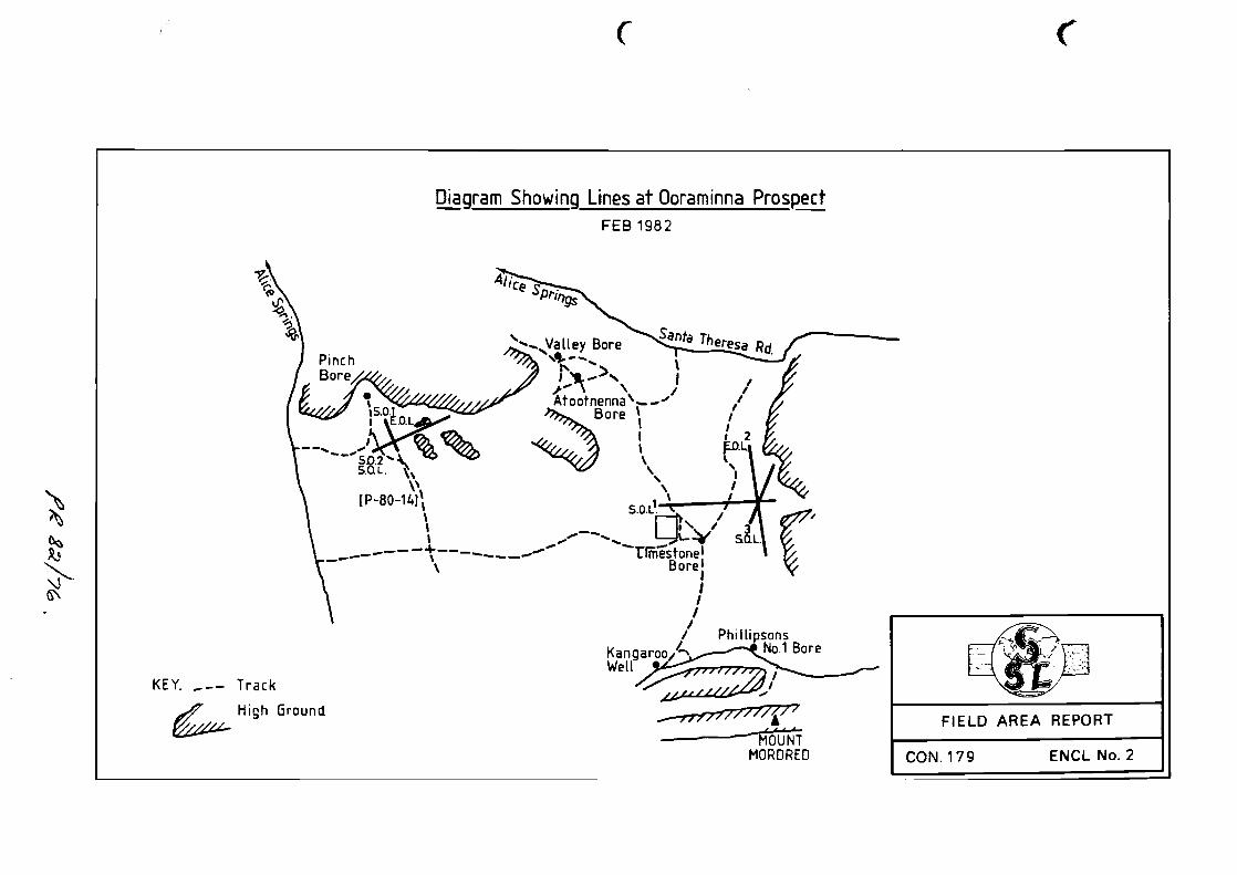
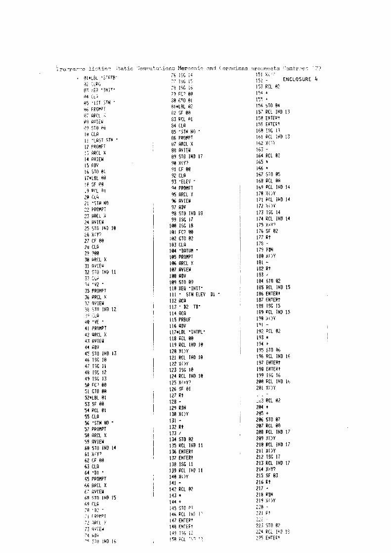

( ( (
Horizontal amp Vertical LOOR Closure Diagram
Mereenie Prospect
1(1 middot
----~~~~~~~v~~~~~~-t~~~~~J~~~~--~~5~7~------_f~~~------~~~8
18 14
~__~~~~_____ 5-3N D~J~~ 9-3D 12087 -0-6 -~-m li -shy - 5
131
12
FIELDAll loops close c1ockwjse AREA REPORT
Not to Sc~ale ENCL No5