influence of material flow in compression molding...
TRANSCRIPT

THE 19TH INTERNATIONAL CONFERENCE ON COMPOSITE MATERIALS
1 Introduction In recent years, several measures for the better global environment have been taken in a variety of different fields. In a transportation sector, it is expected to install lightweight materials to automotive body structure for fuel efficiency. Carbon fiber reinforced thermosetting plastics (CFRTS) have been mainly used as a material for aircrafts, while in recent years, carbon fiber reinforced thermoplastics (CFRTP) have particularly been expected as a promising material for automobiles because of their high-cycle manufacturing. Among several kinds of CFRTP, discontinuous CFRTP are especially expected as a material for products with complex shape, because of its high formability. Discontinuous CFRTP is expected to be formed by compression molding. However, material flow during manufacturing process is well known to affect fiber distribution and hence mechanical properties of discontinuous FRP products. [1] It is expected that discontinuous CFRTP is formed through compression molding. During molding, state of reinforcement may be influenced because fiber distribution and orientation change, and mechanical properties are changed from materials before molding. However, relationship between compression molding and reinforcement of CFRTP has not been
investigated. Then, in order to know influences of compression molding to mechanical properties of material flow during compression molding, flexural properties of materials after molding were compared with originals. In this study, the mechanical expanding rate in compression molding was varied to investigate the influence of material flow during molding on flexural properties of two types of molded materials, CMT and CTT. In this study, how states of reinforcement of CFRTP change by different press conditions of compression molding, and how it influences on mechanical properties was investigated.
2 Experimental procedure
2.1 Materials for Compression molding
Two types of CFRTP were used in this test; The tested materials were carbon fiber mat reinforced thermoplastics (CMT) preform as shown in Fig.1 and chopped carbon fiber tape reinforced thermoplastics (CTT) preform as shown in Fig.2. A sheet of CMT preform is 1 mm in thickness, which consists of four layers of carbon mat sheets. Each fiber from carbon fiber mat is dispersed randomly and hence CMT shows quasi-isotropy in plane. CTT preform also shows isotropy, since it is composed of
INFLUENCE OF MATERIAL FLOW IN COMPRESSION MOLDING ON MECHANICAL PROPERTIES OF
DISCONTINUOUS CF/PP
N. Mitsui1*, K. Kageyama1, K. Uzawa2, I. Ohsawa3, and J. Takahashi3
1 Department of Technology Management for Innovation, School of Engineering,
The University of Tokyo, Tokyo, Japan 2 Graduate Program in Synthesized Engineering, School of Engineering,
Kanazawa Institute of Technology, Ishikawa, Japan 3 Department of Systems Innovation, School of Engineering, The University of Tokyo, Tokyo,
Japan
* Corresponding author ([email protected])
Keywords: CFRTP, material flow, fiber orientation

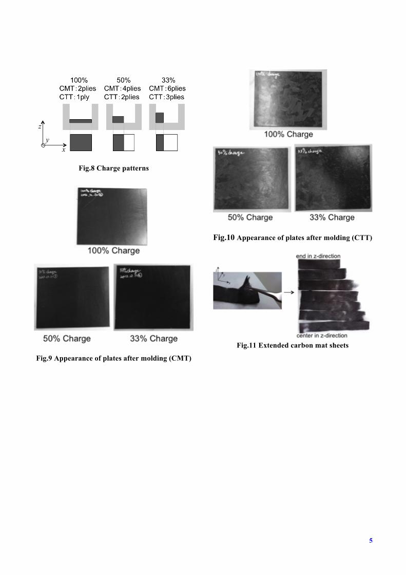
randomly dispersed UD chopped tapes. Table 1 shows the basic specifications of these preforms. 2.2 Investigation of test conditions In order to investigate general aspect of compressed discontinuous CFRTP, simple compression tests were performed on cylindrical samples of CMT and CTT. Samples were squeezed between two plates. Initial diameter was 50 mm. Seven different loads were tested. Four different temperatures were tested, i.e. 170℃ , 180℃ , 190℃ and 200℃ . The thickness of compressed samples was recorded after the experiments. Fig.3 and Fig.4 show typical specimens before and after compression of CMT and CTT. Fig.5 and Fig.6 show thickness of compressed specimens of each initial pressure. It was found out from the obtained data that there were big difference between thickness of samples compressed with 5 MPa and 10 MPa. And there were also big difference between thickness of samples compressed under 170℃ and 180℃. 2.3 Conditions of Compression Molding In order to investigate characteristics of materials after molding, the preforms were pressed under different conditions. Fig.7 shows a schematic diagram of compression molding. A press machine used in this study was equipped with a rectangular mold of 240 mm×200 mm. As shown in Fig.8, tested ratios of charge(area ratio) were 100%, 50%, and 33%. Initial height h of which were 2, 4, and 6 mm, so that the thickness of compressed material became 2 mm. Molding temperatures were 180℃ and 200℃.
2.4 Observation
States of molded plates were observed. Fig.9 and Fig.10 show appearances of CMT and CTT plates after molding. Materials were fully extended in x-direction under each pattern of charge (100%, 50%, and 33%). In order to observe structure of remained carbon fiber, the resins of the molded plates of CMT under the various conditions were burnt out at 400℃. As seen in Fig.11, layers of a
piece of a plate after burned were separated. Length in x-direction of extended carbon mat sheet was different from sheet to sheet. Inner layers of CMT were fully extended in x-direction, while outer layers were not. The external layer was only extended 20% of initial length in both 50% and 33% charge plates. Fig.12 shows 50% charge CTT before and after molding. A line which had marked on the edge of the plate before molding moved about 20% in x-direction. Fig.13 and Fig.14 show in a schematic manner how materials are compressed in z-direction and extended in compression molding in CMT plate and CTT plate.
2.5 Three-point bending test
To understand the influence of material flow on the strength of the material, three-point bending test was conducted. The flexural strength is
(1)
where is a maximum load, L is a span length (32 mm), w is a specimen width (15 mm), and t is a specimen thickness (2 mm).
In order to know whether strength show isotropy in the molded plate or not, 13 CMT specimens were cut from 90° to the material flow direction (x-direction), and seven specimens from 0° , as shown in Fig.15 and Fig.16 (outer line is an edge of a molded plate). Six CTT specimens were cut from 90° to the material flow direction, and 3 specimens from 0°. Fig.17 and Fig.18 show volume fraction (Vf) of the molded CMT plate and CTT plate.
3 Results and Discussion
3.1 Results of three-point bending tests
The test result of flexural strength is shown in Fig.19 and Fig.20.
!max
!max =32PmaxLwt2
Pmax
!max

3
It was found out from the obtained data that the flexural strength of specimens cut from 90°was smaller than initial strength (strength of specimens cut from materials compressed in condition of 100% ratio of charge) of both CMT and CTT. The flexural strength of CMT specimens cut from 0°was also smaller than initial strength, while larger in CTT. Difference between flexural strength between plates of 50% and 33% in charge pattern was not clear. Difference between flexural strength between plates molded at 180℃ and 200℃ was not clear.
3.2 Fiber distribution
As shown in Fig.11, only inner layer of mat was extended completely because of fountain flow in CMT. Outer layer was extended by 10% of initial length. Interlayer slip was observed because interlayer friction is bigger than in-layer friction. As shown in Fig.12, only inner part of the material was extended completely because of fountain flow in CTT. Outer part was extended by 10% of initial length.
3.3 Volume fraction
As shown in Fig.17 and Fig.18, difference of volume fraction (Vf) of different position of CMT in x-direction was no bigger than 2.5%. Also, difference of Vf of different position of CTT in x-direction is no bigger than 1.0%, as shown in Fig.13. Thus, changes of flexural strength of molded plates were not the result of the change or difference of Vf.
3.4 Fiber orientation
The molded plates under the various conditions were burnt to take the photograph for investigation of fiber distribution and orientation. In addition, a microscope was used to investigate the fiber distributions and orientations in the specimens. In Fig.21, the photographs obtained from the burnt specimen are given. It can be seen in this figure that some fibers were aligned to the flow direction at the original (①) and the center region (②). At the edge region (③), many fibers are parallel to the side wall.
4 Conclusions
It became clear that flexural properties were greatly influenced by anisotropic fiber orientation occurred during material flow. In CMT, mechanical properties dropped in both directions because of interlayer slip. The fibers were distributed randomly at the beginning, but the orientation and distribution were aligned to the material flow direction. Mechanical property of CTT specimens cut from 0°improved. Thus, condition during compression molding is important in obtaining in-plane isotropic mechanical properties.
Fig.1 Structure of CMT
Fig.2 Structure of CTT
CFモノフィラメント(6~7mm)
ランダムに配列
CF mono filament

Table 1 Properties of base materials CTT CMT Reinforcement (CF) TR50S T700
CF/PP
Vf 45% 20% Interfacial Shear Strengthi 17.7 MPa 13.3 MPa
Interlaminar Shear Strengthii 13.1 MPa 28.7 MPa
iFragmentation Test, iiDouble-notch Shear Strength Test[JIS K7092].
Fig.3 Typical simple compression experiments
(CMT)
Fig.4 Typical simple compression experiments
(CTT)
Fig.5 Thickness of specimens under each initial
pressure (CMT)
Fig.6 Thickness of specimens under each initial
pressure (CTT)
Fig. 7 Schematic diagram of compression
molding
!"##
# #図# $%&!#'()材の厚さと荷重の関係#
#
#図# $%&$#'))材の厚さと荷重の関係#
#
!
!"#
!"$
!"%
!"&
'
'"#
! '! #! (! $!
厚さ)*
*+
圧力),-.+
#!!℃'/!℃'&!℃'0!℃
!
!"1
'
'"1
#
! '! #! (! $!
厚さ)*
*+
圧力),-.+
#!!℃
'/!℃
'&!℃
'0!℃
pressure [mm]
thic
knes
s [m
m]
!"##
# #図# $%&!#'()材の厚さと荷重の関係#
#
#図# $%&$#'))材の厚さと荷重の関係#
#
!
!"#
!"$
!"%
!"&
'
'"#
! '! #! (! $!
厚さ)*
*+
圧力),-.+
#!!℃'/!℃'&!℃'0!℃
!
!"1
'
'"1
#
! '! #! (! $!
厚さ)*
*+
圧力),-.+
#!!℃
'/!℃
'&!℃
'0!℃
pressure [mm]
thic
knes
s [m
m]
mold
material
5
Fig.8 Charge patterns
Fig.9 Appearance of plates after molding (CMT)
Fig.10 Appearance of plates after molding (CTT)
Fig.11 Extended carbon mat sheets
z
xy

Fig.12 CTT plate before and after molding
Fig.13 Molded model of CMT
Fig.14 Molded model of CTT
Fig.15 Specimen cut pattern
(90°specimen)
! " #$ % & ' !( !! !) !$) *
!"#
$%%&
&
$'%&&
(%&&
)(&&
+,-./0123451-6

7
Fig.16 Specimen cut pattern
(0°specimen)
Fig.17 Vf (CMT)
Fig.18 Vf (CTT)
Fig.19 Test result (90°specimen)
Fig.20 Test result (0°specimen)
!"#
$%%&&
$'%&&
!"#$%&'()*+'#,
- ./ 01 23 ()&&
)%&&
!""#
#$
33% Charge CMT25
20
15
10
5
0
Vf [
%]
place of specimen x
33% Charge CTT
40
20
30
10
0
Vf [
%]
place of specimen x
50
60
!
"!!
#!!
$!!
%!!
&!!
'!!
!"#$%&'$!()*+, !"#$--'$!()*+, !##$%&'$!()*+, !##$--'$!()*+,
曲げ強度
."/)0
"(!℃ ()!度方向)#!!℃ ()!度方向)"!!*+,-./01
フレッシュ材
"(!℃#!!℃
!"#$%&'"()*&#+,*-(./
0'1( 233
433
533
633
733
833
9/:(43;(9-'&,#
((((3 9/:(66;(9-'&,#
9::(66;(9-'&,#
9::(43;(9-'&,#
8<3℃(733℃(
833;(9-'&,#
!
"!!
#!!
$!!
%!!
&!!
'!!
!"#$%&'$!()*+, !"#$--'$!()*+, !##$%&'$!()*+, !##$--'$!()*+,
曲げ強度
."/)0
"(!℃ (!度方向)#!!℃ (!度方向)"!!)*+,-./0
!"#$%&'"()*&#+,*-(./
0'1( 233
433
533
633
733
833
9/:(43;(9-'&,#
((((3 9/:(66;(9-'&,#
9::(66;(9-'&,#
9::(43;(9-'&,#
8<3℃(733℃(
833;(9-'&,#
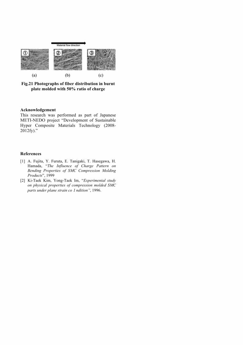
Fig.21 Photographs of fiber distribution in burnt
plate molded with 50% ratio of charge
Acknowledgement This research was performed as part of Japanese METI-NEDO project “Development of Sustainable Hyper Composite Materials Technology (2008-2012fy).”
References [1] A. Fujita, Y. Furuta, E. Tanigaki, T. Hasegawa, H.
Hamada, “The Influence of Charge Pattern on Bending Properties of SMC Compression Molding Products”, 1999
[2] Ki-Taek Kim, Yong-Taek Im, “Experimental study on physical properties of compression molded SMC parts under plane strain co1ndition”, 1996.