influence of fretting on flexural fatigue of 304 stainless ... · flexural fatigue of 304 stainless...
TRANSCRIPT

.
NASA Technical Paper 1193
Influence of Fretting on
I
I I
1 NASA j TP
, c.1 'j 1193
i
~' , j
Flexural Fatigue of 304 Stainless Steel and Mild Steel /
\
Robert C. Bill and Douglas A. Rohn
APRIL 1978
NASA
_-
I
https://ntrs.nasa.gov/search.jsp?R=19780013326 2018-07-14T03:57:35+00:00Z

. ._
TECH LIBRARY KAFB, NM
I llll1111111111111llll11 lllll lllll11llllll 01 3'4 5 5 0
NASA Technical Paper 1193
Influence of Fretting on Flexural Fatigue of 304 Stainless Steel and Mild Steel
Robert C . Bill Propulsion Laboratory U S . Army R G T Laboratories {AVRADCOM) Lewis Research Center, Cleveland, Ohio
and
Douglas A. Rohn Lewis Research Center Cleveland, Ohio
NASA National Aeronautics and Space Administration
Scientific and Technical Information Office
1978

INFLUENCE OF FREll lNG ON FLEXURAL FATIGUE OF
304 STAINLESS STEEL AND MILD STEEL
by Robert C. Bil l* and Douglas A. Rohn
Lewis Research Center
SUMMARY
Fretting fatigue experiments were conducted on 304 stainless steel and on mild steel. The test configuration was a flexural fatigue arrangement, with mild steel fret- ting pads bolted onto the fatigue specimen. Experiments were conducted at room tem- perature in air.
Fretting reduced the flexural fatigue life of 304 stainless steel by at least a factor of 10 at alternating flexural-fatigue stresses in the 265- to 334-megapascal range. In addition, experiments in which the fretting pads were removed after a number of cycles followed by continued fatigue without fretting showed that continued fretting be- yond 50 000 cycles does not significantly further reduce the fatigue life of 304 stainless steel at 317 megapascals (46 000 psi). Microscopic examination indicated that failures invariably began in the fretting region. Cracks that did not propagate to failure were also observed in the fretted areas.
Flexural-f retting-fatigue experiments conducted on mild steel showed an insensitiv- ity of fatigue life to the incidence of fretting under alternating flexural stresses of from 162 to 217 megapascals. This was thought to be due to compressive residual stresses developed in the fretting-pad contact areas due to local yielding under combined contact and fatigue stresses.
INTRODUCTION
Fretting is a wear or surface damage phenomenon resulting from low-amplitude oscillatory motion between two mating surfaces. The result of fretting is reduced life or strength. The detrimental effect of fretting on the fatigue life of mechanical com- ponents is well known and documented (refs. 1 to 3). Depending on material combina-
*Propulsion Laboratory, U. S. Army R&T Laboratories (AVRADCOM).

tion and stress conditions, reductions in fatigue strength by a factor of four or more are common (ref. 4).
the prevailing theories strongly consider the role of frictional-stress concentrations assockted with the fretting action.
the fretting-frictional force as the primary cause of crack initiation and developed a relationship for predicting stress-concentration levels. Roberts (ref. 6) varied the con- tact geometry in fretting-fatigue experiments and concluded that frictional-stress con- centrations on both the macroscopic (overall contact geometry) and microscopic (asper - ity) levels were significant initiators of cracks. Experiments by Waterhouse and Taylor (ref. 7) showed that cracks originate at the boundary between slip and nonslip regions within the overall contact area, where frictional-stress concentrations are the greatest.
The effects of experimental variables such as the direction of fretting motion (ref. 8) , normal load levels (ref. 9), fretting exposure cycles (ref. lo), and slip ampli- tude have been studied and a re generally consistent with the concept of frictionally in- duced stress concentration. A cautionary note is in order, however: Experiments per- formed by Waterhouse in a corrosive environment (ref. 11) indicate the importance of a chemical contribution to the fretting-fatigue process, probably through a stress- corrosion-cracking-related mechanism. Furthermore, the extent and nature of fretting wear in the contact area have a complex influence on fretting fatigue life, as illustrated by the work of Malkin, et. al. (ref. 12).
The purpose of this paper is to describe the fretting-fatigue characteristics of 304 stainless steel, an important structural material that has not been extensively investi- gated, and compare them with those of mild steel. Three kinds of experiments were conducted: (1) Specimens were subjected to flexural-fatigue without fretting; (2) speci- mens were subjected to a prescribed number of flexural fatigue cycles with fretting (fretting fatigue), then the fretting pads were removed and flexural fatigue was continued to failure (These experiments are referred to as "two part" fretting experiments.); and (3) specimens were subjected to fretting until failure occurred. A flexural-test configu- ration was used, and experiments were conducted in ambient conditions (room tempera- ture air, 25 to 45 percent relative humidity) without lubricants or coatings. Fretted regions and areas of crack initiation were examined by optical and scanning electron microscopy.
The causes of fatigue-life reductions due to fretting a re not clearly understood, but
Nishioka and Hirakawa (ref. 5) identified the s t ress concentrations resulting from
SYMBOLS
a crack tip (slip front) radius, m
b half-width of Hertzian contact area, m
2

E
Ff
FG I
I?
M
r
t
U
V
X
E st I-1
U
uf
oct U
Young's modulus, Pa
frictional force, N
force promoting growth of slip region, N
area moment of inertia, m
slip region length, m
applied flexural fatigue bending moment, N-m
maximum Hertzian contact stress, MPa
distance from slip front, m
fatigue specimen thickness, m
surface displacement in slip region, m
strain energy, J
distance from edge of contact region to arbitrary point in slip region, m
surface tensile strain
coefficient of friction
stress, MPa
normal contact stress, MPa
flexural fatigue stress, MPa
equivalent octahedral shear stress, MPa
4
APPARATUS, SPECIMEN, AND PROCEDURE:
Apparatus
The fretting-fatigue apparatus used in this investigation is shown in figure l(a). The standard flexural-fatigue machine consists of a variable-speed motor, eccentric head, connecting rod, specimen grip, and vise clamp. Rotation of the head causes the connecting rod to flex the end of the specimen. The eccentric head can be set to provide zero- to 5.08-centimeter (2-in. ), peak-to-peak deflection at the end of the connecting rod. Flexural stresses can be calculated from this deflection considering specimen geometry and material constants. A counter records head revolutions, and after speci- men failure a shutdown switch is tripped by the connecting rod.
3

Specimen
The fatigue specimen is in the form of a constant-stress-cross-section, flexural sheet, 0.75-millimeter (0.030-in. ) thick. A s indicate in figure l(b) the specimen geom- etry is basically triangular. The relation between width and height of this triangle is determined so that, when end loaded as a cantilever beam, the ratio of bending moment to cross-sectional moment of inertia is the same at all points along the specimen. Thus the bending stresses are equal over the beam's length. Outside the constant-stress area are the vise mounting and connecting rod clamping areas, with fillets to reduce s t ress concentrations.
As indicated in figure l(b), two holes are provided in the constant-stress portion of all specimens to permit mounting of the fretting pads. The stress concentration factor associated with the mounting holes is calculated to be 1.59 (ref. 13). All fatigue-stress levels discussed reflect nominal flexural stresses in the fatigue specimen, and do not consider stress-concentration effects due to the presence of the holes.
The 304 stainlesssteel fatigue specimens were machined from cold-rolled, an- nealed, 0.78-millimeter (0.031-in.) thick stock. To relieve any residual stresses around the holes provided for mounting of the fretting pads, a 1-hour stress-relief heat treatment at 700° F was applied. Carbon-steel fatigue specimens were machined from hot-rolled, 0.76-millimeter (0.030-in. ) thick, 1020 sheet. Fretting pads were ma- chined from mild steel, and the contact surface was ground to a 25.4-millimeter (1-in.) radius (fig. l(c)). These pads were used with both the mild steel and 304 stainless- steel fatigue specimens. All fatigue specimens and fretting-pad surfaces were thorough- ly scrubbed with levigated alumina (particle size, 0.5 pm) and rinsed with ethanol be- fore being assembled and inserted into the fatigue apparatus.
Procedure
To produce fretting, pads were bolted to the upper and lower surfaces of the fatigue specimens, and the normal load was applied by tightening the bolts to a controlled torque. This normal loading results in a frictional force between the pads and the specimen sur- face which opposes the strain motion driven by the bending moment. Fretting occurs around the edges of the Hertzian contact area where the force that promotes slip exceeds the restraining friction. Further details are given in appendix A. A torque of 1.14 newton-meters (10 in. -Ib) was applied in all fretting-fatigue experiments. With an assumed bolt-friction coefficient of 0.15, the corresponding peak Hertzian stress is 172 megapascals (25 000 psi) with a contact width of approximately 250 micrometers (0.010 in.).
4
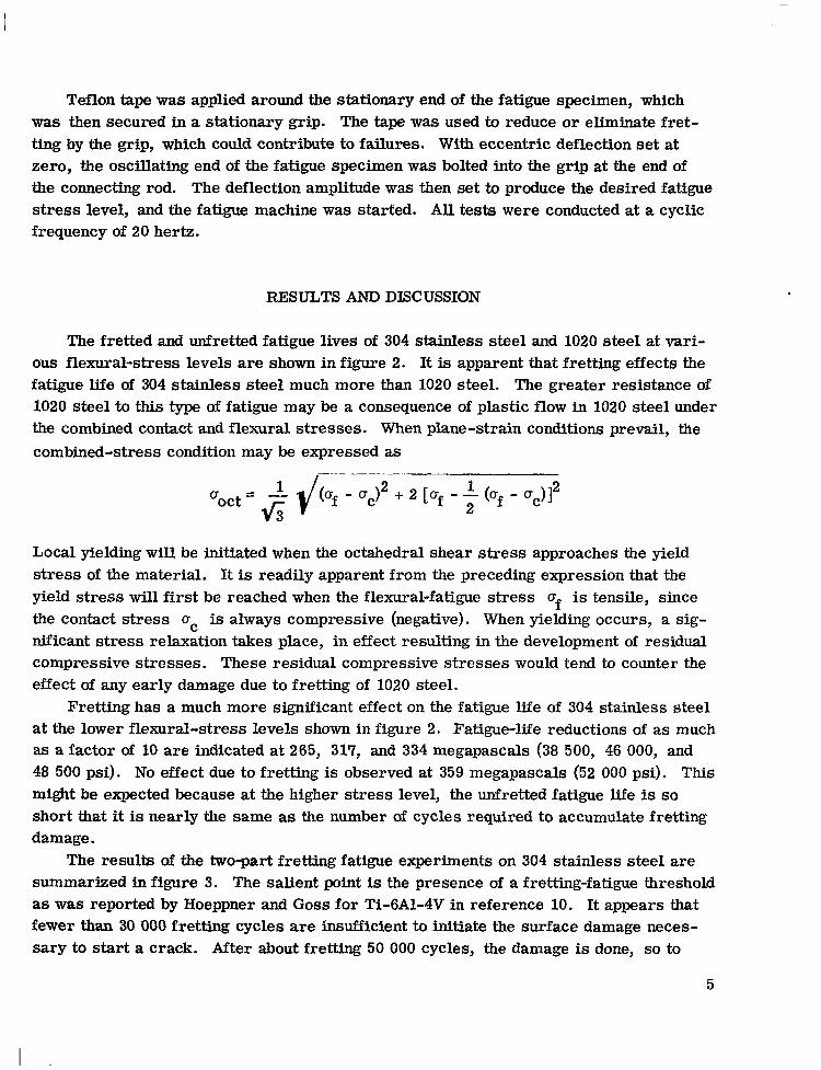
Teflon tape was applied around the stationary end of the fatigue specimen, which was then secured in a stationary grip. The tape was used to reduce or eliminate fret- ting by the grip, which could contribute to failures. With eccentric deflection set at zero, the oscillating end of the fatigue specimen was bolted into the grip at the end of the connecting rod. The deflection amplitude was then set to produce the desired fatigue stress level, and the fatigue machine was started. All tests were conducted at a cyclic frequency of 20 hertz.
RESULTS AND DISCUSSION
The fretted and unfretted fatigue lives of 304 stainless steel and 1020 steel at vari- ous flexural-stress levels a re shown in figure 2. It is apparent that fretting effects the fatigue life of 304 stainless steel much more than 1020 steel. The greater resistance of 1020 steel to this type of fatigue may be a consequence of plastic flow in 1020 steel under the combined contact and flexural stresses. When plane-strain conditions prevail, the combined-stress condition may be expressed a s
Local yielding will be initiated when the octahedral shear stress approac,,es the yield stress of the material. It is readily apparent from the preceding expression that the yield stress will first be reached when the flexural-fatigue stress of is tensile, since the contact stress uc is always compressive (negative). When yielding occurs, a sig- nificant stress relaxation takes place, in effect resulting in the development of residual compressive stresses. These residual compressive stresses would tend to counter the effect of any early damage due to fretting of 1020 steel.
Fretting has a much more significant effect on the fatigue life of 304 stainless steel at the lower flexural-stress levels shown in figure 2. Fatigue-life reductions of as much as a factor of 10 are indicated at 265, 317, and 334 megapascals (38 500, 46 000, and 48 500 psi). No effect due to fretting is observed at 359 megapascals (52 000 psi). This might be expected because at the higher s t ress level, the unfretted fatigue life is so short that it is nearly the same as the number of cycles required to accumulate fretting damage.
The results of the two-part fretting fatigue experiments on 304 stainless steel are summarized in figure 3. The salient point is the presence of a fretting-fatigue threshold as was reported by Hoeppner and Goss for Ti-6A1-4V in reference 10. It appears that fewer than 30 000 fretting cycles are insufficient to initiate the surface damage neces- sary to start a crack. After about fretting 50 000 cycles, the damage is done, so to
5

speak. Fatigue life is not systematically shortened by exposure to further fretting damage.
The fretting-pad contact pattern seen on the fatigue specimen surface after failure is shown schematically in figure 4. There are two distinct regions associated with the contact area, namely, regions of slip and regions of nonslip. Slip regions completely enclose the nonslip central regions, and are characterized by very fine fretting surface damage, as may be seen in figure 5. The nonslip central regions show virtually to evidence of surface distress.
The average width of the fretting pad contact area is about 750 to 1000 micrometers (0.030 to 0.040 in. ), rather than the 250 micrometers (0.010 in. ) predicted from Hertz- ian contact equations. There are two effects contributing to this discrepancy: First, the cylinder-on-flat contact is interrupted over the assumed 2.54-centimeter (1-in.) length by the relief around the bolt holes, with consequently reduced effective contact length, increased Hertzian stresses, and increased contact width. Second, since the flexural-fatigue specimen is only 750 micrometers (0.030 in.) thick, some overlap of the contact stresses due to the fretting pads clamped on either side of the specimen might occur. Again, increased contact width would be expected.
Examination of fretting-fatigue specimens indicates that both the primary fatigue crack (the one that led to final failure) and secondary cracks that did not propagate to failure began in the slip regions of the contact area. Figure 5 clearly shows the inter- action of the fretting region with the final fatigue failure, as well as numerous fine cracks near the fracture edge that did not propagate to failure. The fracture surface (fig. 5(b)) correlates with the plan view (fig. 5(a)) and shows numerous crack-initiation sites.
ture surface, as may be seen in figure 6. The especially heavy fretting surface damage in figure 6(b) on the side of the crack toward the vise grip is due to a "secondary" fret- ting effect. After the crack was able to propagate a considerable distance along the fatigue specimen, slip motion no longer varied smoothly over the original slip region. Rather, the crack acted as sort of a hinge forcing increased relative motion between the fretting pad and that part of the fatigue specimen toward the vise grip.
A section view of a fretting fatigue fracture surface is shown in figure 7. Evidence of surface pitting due to the fretting action may be seen. Of particular interest is the crack that was initiated in the fretting area but did not link up with the primary crack.
Fracture-surface features on the flexural-fatigue specimens are shown in figure 8. Two distinct regions are seen on the fracture surface. Near the contact surface where fretting takes place, there is evidence of rapid crack growth into the fatigue specimen, as indicated by the distinctly striated areas. With increasing depth into the fatigue specimen, a region is encountered in which cracks propagate parallel to the bending
Cracks were also observed in the fretted, slip region, not adjacent to the final frac-
6

axis as well as into the specimen. face of figure 8(b) are caused by adherent, compacted fretting debris.
The amplitude of motion promoting fretting damage in the slip region may be esti- mated by considering the driving force tending to extend the slip region. Strain energy in the fatigue specimen integrated between the extremities of the slip region provides this driving force. Opposing the driving force is the total frictional traction developed between the slip surfaces. (Detail of this analysis are given in the appendix. ) Briefly, it is predicted that slip occurs over 2.5-micrometer (0.0001-in. ) wide region at the edges of the contact zones. Slip amplitudes would thus be in the micrometer range. The photomicrographs in figure 5, showing the fretting damage, indicate surface dis- t ress over a region of about 25 micrometers rather than the 2.5 micrometers predicted. The discrepancy is likely due to the effect of entrapped abrasive debris and to alter- nating degrees of conformance between the pad and flexural specimen during the fatigue cycle. Thus, the procedure outlined in the appendix is suggested as an approach to estimating fretting conditions in nominal no slip contact situations.
The "smeared" appearing areas on the fracture sur-
CONCLUSIONS
Based on the flexural fretting fatigue experiments conducted on 304 stainless steel
1. The flexural fatigue life of 304 stainless steel is reduced by approximately a
2 . Fretting damage reduced fatigue life within approximately the first 50 000 fret-
3. Fatigue cracks initiated in the fretting region, although cracks that did not pro-
4. The fatigue life of mild steel was less affected by fretting than was that of 304
and on mild steel, the following conclusions are drawn:
factor of 10 in the 265- to 334-megapascal flexural-fatigue-stress range.
ting fatigue cycles in 304 stainless steel.
pagate failure are also seen in this region.
stainless steel.
Lewis Research Center, National Aeronautics and Space Administration,
Cleveland, Ohio, 1/18/78, 505-04.
7
I
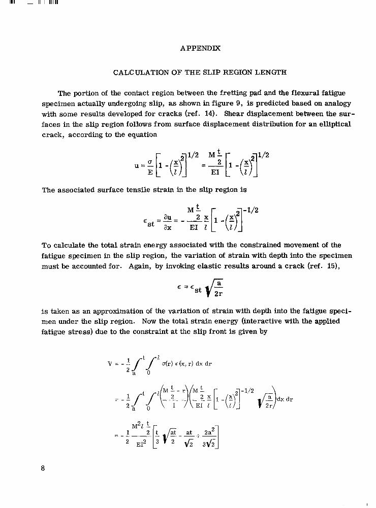
APPENDIX
CALCULATION OF THE SLIP REGION LENGTH
The portion of the contact region between the fretting pad and the flexural fatigue specimen actually undergoing slip, as shown in figure 9, is predicted based on analogy with some results developed for cracks (ref. 14). Shear displacement between the sur- faces in the slip region follows from surface displacement distribution for an elliptical crack, according to the equation
The associated surface tensile strain in the slip region is
To calculate the total strain energy associated with the constrained movement of the fatigue specimen in the slip region, the variation of strain with depth into the specimen must be accounted for. Again, by invoking elastic results around a crack (ref. 15),
is taken as an approximation of the variation of strain with depth into the fatigue speci- men under the slip region. Now the total strain energy (interactive with the applied fatigue stress) due to the constraint at the slip front is given by
V = - A I t $ ' U(r ) ~ ( x , r) dx dr 2 a
2 t M t -
E12
1
8

I -_.
The force, driven by the applied bending stress and tending to promote growth of the slip region, is
This force must exceed a retarding frictional force for growth to occur. Hence, the length of the slip region 2 is defined when the frictional force equals -av/aZ. The frictional force is calculated by integrating the normal contact force between the fretting pad and the fatigue specimen over the contact length and multiplying by a friction coeffi- cient:
= ,upo le 42b2-2 2 +-sin b -1 - 2-b - b - - 1 3~ 2b 2 b 2 2
Slip region length is now determined by setting FG = Ff and solving iteratively for 2 :
The solution was based on conditions for 304 stainless steel tested under a 317- megapascal (46 000-psi) flexural stress with a 69-megapascal (10 000-psi) maximum Hertzian stress Po. The value of a was taken to be approximately the surface rough- ness of the fatigue specimen, about 0.60 micrometers (25 pin. ); p, the coefficient of friction, was chosen to be 0.5; and b, the contact half-width, was chosen to be 500 micrometers (0.02 in.). The values of b and Po are based on posttest measurements of actual f retting-pad-contact dimensions rather than on predicted Hertzian values. It is found that under these conditions FG = Ff is satisfied when 2 is about 2 .5 micro- meters (0.0001 in.).
9

REFERENCES
1. Lee, J. R. : Fretting in Helicopters. Specialists Meeting on Fretting in Aircraft Systems. AGARD CP-161, 1974, pp. 3-1 to 3-10.
2 . Johnson, Robert L. ; and Bill, Robert C. : Fretting in Aircraft Turbine Engines. Specialists Meeting on Fretting in Aircraf t Systems. AGARD CP-161, 1974, pp. 5-1 to 5-17.
3. Sandifer, J. Paul: Evaluation of Methods for Reducing Fretting Fatigue Damage in 2024-T3 Aluminum Lap Joints. Wear , vol. 26, 1973, pp. 405-412.
4. Harr i s , W. J. : The Influence of Fretting on Fatigue, Pt. III. Advisory Group for Aerospace Research and Development (Paris), AGARD AR-45, 1972.
5. Nishioka, Kunis; and Hirakawa, Kenji: Fundamental Investigations of Fretting Fatigue. pt. 3 - Some Phenomena and Mechanisms of Surface Cracks. Bull. Jap. SOC. Mech. Eng., vol. 12, no. 51, June 1969, pp. 397-407.
6. Roberts, Graham: The Effect of Contact Geometry on Fretting Fatigue. Fracture Control Program Rept. No. 17, Univ. of Ill., 1975.
Carbon Steel by Fretting. Wear , vol. 17, 1971, pp. 139-147. 7. Waterhouse, R. B. ; and Taylor, D. E. : The Initiation of Fatigue Cracks in a 0.7%
8. Collins, J. A. ; and Tovey, F. M. : Fretting-Fatigue Mechanisms and the Effect of Direction of Fretting Motion on Fatigue Strength. J. Mater., vol. 7, no. 4, Dec. 1972, pp. 460-464.
by SEM Analysis. Wear, vol. 24, 1973, pp. 77-95.
cept. Wear, vol. 27, 1974, pp. 61-70.
9. GOSS, G. L. ; and Hoeppner, D. W. : Characterization of Fretting Fatigue Damage
10. Hoeppner, D. W. ; and Goss, G. L. : A Fretting-Fatigue Damage Threshold Con-
11. Waterhouse, R. B. ; and Dutta, M. K. : The Fretting Fatigue of Titanium and Some Titanium Alloys in a Corrosive Environment. Wear, vol. 25, 1973, pp. 171-175.
12. Malkin, S. ; Majors, D. P. ; and Courtney, T. H. : Surface Effects During Fretting Fatigue of Ti-6A1-4V. Wear, vol. 22, 1972, pp. 235-244.
13. Roark, Raymond J.; and Young, Warren C.: Formulas for Stress and Strain. Fifth ed., McGraw-Hill Book Co., Inc., 1975, p. 595.
14. Eshelby, J. D. : The Determination of the Elastic Field of an Ellipsoidal Inclusion and Related Problems. Proc. Roy. SOC. (London), Ser. A, vol. 241, no. 1226, Aug. 1957, pp. 376-396.
15. McClintock, Frank A. ; Argon, Ali S., eds. : Mechanical Behavior of Materials. Addison-Wesley, 1966, pp. 403-410.
10

0 Fatigue without fretting 0 Fretting fatigue
al 3 .- m
la) Flexural fretting fatigue apparatus. (No failure)
Point of load application -\
\
8.25 cm 1 0.317 cm
- 1.21 cm, Grip area 1.27 cm
oo 0 0 .. 0 (No failure)
0-
0 . 0 8 3 0 00.Q- (No failure)
1% 104 105 106 107
Cycles to failure
Q) 1020 Mi ld steel.
Figure 2. - Fretting fatigue life.
k 5 . 0 8 cm+
(b) Flexural specimen. (c) Fretting pad.
Figure 1. - Test apparatus and specimen.

IIIII I II
500 c c E m L. LL 'I 0
0
0
0
Figure 3. -Two part frett ing fatigue of 3 4 stainless steel. Fatigue stress, i317 megapascals.
\ ' Nonslip region
Figure 4. - Distr ibution of slip and nonsl ip regions in frett ing pad contact area on frett ing fatigue f lexural specimen.
12

I
7-1 . Contact - Top view of region
shown in part 5(c).
(a) Overview of contact region on fractured fretting fatigue specimen.
i
(b) Close-up of edge of fracture surface.
(c) Edge view showing fracture surface.
Figure 5. - Photomicrographs of fretted surface and fracture surface of 304 stainless-steel specimen after fretting fatigue failure under 2317-mega- pascal flexural-fatigue-stress experiment.
13

(a) Region near one of bolt holes. (b) Region showing secondary surface fretting damage.
Figure 6. - Fretting fatigue cracks initiated in fretting region not adjacent to fracture surface. Flexural stress, 2317 megapascals; 304 stainless steel.
14

I I 50 pm
Figure 7. - Section through fracture surface. 304 stainless steel after fretting fatigue failure under 2317-megapascal flexural fatigue stress.
(a) Overview showing area of rapid crack propagation. (b) Close-up showing adherent compacted fretting debris.
Figure 8. - Scanning electron micrographs of fretting fatigue fracture surface on 304 stainless steel. Flexural fatigue stress, t317 megapascals.
15
I II

I I
fretting pad
/- I Fretting pad
r x L b I
specimen ff2
I Centerline of __ flexural fatigue specimen
- t-
Figure 9. - Features of contact geometry of fretting pad and flexural fatigue specimen.
16 E-9414
I

. .. ~ ___ - - .
1. Report No. 2 . Government Accession No.
_ ~~ ~.. I .. . .- NASA TP-1193
4. Title and Subtitle
INFLUENCE OF FRETTING ON FLEXURAL FATIGUE OF 304 STALNLESS STEEL AND MILD STEEL
- -~ -.
7. Author(s)
Robert C. Bill and Douglas A. Rohn . . .. - .. .. ~ ~~
9. Performing Organization Name and Address
NASA Lewis Research Center and Propulsion Laboratory U. S. Army R&T Laboratories (AVRADCOM) Cleveland, ~~- Ohio 44135 ~ . ~ ~-
12. Sponsoring Agency Name and Address
National Aeronautics and Space Administration Washington, D. C. 20546
- - ... .~ __-__~ - .. 15. Supplementary Notes
9. Security Classif. (of this report1
Unclassified -. - ~.
..
3. Recipient's Catalog No.
20. Security Classif. (of this page) 1 21. NO. ;7;ges 22. Price' I A02 .- .. .
Unclassified ~.
~~ . . - 5. Report Date
Apr i l 1978 _ _ _ _ . ~ .
6. Performing Organization Code
~ . .
8. Performing Organization Report No.
- .. - E-9414
10. Work Unit No.
505-04 ~. 11. Contract or Grant No.
~ . . .
13. Type of Report and Period Covered
Technical ~~ ~~ - Paper _ _ - 14. Sponsoring Agency Code
~ __ - __ - -- ~ .
16 Abstract
Fretting fatigue experiments conducted on 304 stainless steel using a flexural-fatigue test arrangement with bolted-on fretting pads have demonstrated that fatigue life is reduced by a t least a factor of 10 in the 265- to 334-MPa (38 500- to 48 500-psi) nominal-flexural-fatigue-stre: range. In addition, experiments in which the fretting pads were removed after selected numbers of cycles, followed by continued flexural fatigue without fretting show that continued fretting be- yond 50 000 cycles does not significantly further reduce fatigue life of 304 stainless steel a t 317 MPa (46 000 psi). Microscopic examination of the fretted contact areas revealed fracture initiation sites as well a s numerous cracks that did not propagate to failure. F lexuid fretting fatigue experiments performed on mild steel showed an insensitivity of fatigue life to the inci- dence of fretting under flexural stress conditions of from 162 to 217 MPa (23 500 to 31 500 psi).
~~
7. Key Words (Suggested by Author(s) I
Fretting; Fretting fatigue; Fatigue; Contact stress; Slip amplitude
- . . . -. .
18. Distribution Statement
Unclassified - unlimited STAR Category 26
NASA-Langley, 1978

SPECIAL FOURTH CLASS M A I L BOOK
National Aeronautics and Space Administration
Postage and Fees Paid National Aeronautics and Space Administration N A S A 4 5 1
Washington, D.C. 20546 Official Business Penalty for Private Use, $300
%
.- I' 14 1 1u,c, 040878 S00903DS DEPT O F T H E A I R FnRCF:
ATTN: T E C H # I C A L L I B R A R Y (SUI,) A F W E A P O N S L m o R h s r o R Y K'EPTLP.WD A F R N Y 87117 1 :
POSTMASTER: If Undeliverable (Section 138 Postal Manual) Do Not Return
,