infineon dap active probe v1 - isystem - isystem ... you suspect damage may have occurred, the...
TRANSCRIPT
Infineon DAP Active Probe V1.4
User Manual

This document and all documents accompanying it are copyrighted by iSYSTEM and all rights are reserved. Duplication of these documents is allowed for personal use. For every other case a written consent from iSYSTEM is required. Copyright iSYSTEM, AG. All rights reserved. All trademarks are property of their respective owners. iSYSTEM is ISO 9001 certified company. www.isystem.com

Contents Introduction ................................................................................................................................. 1
Package content .......................................................................................................................... 3
Specifications ............................................................................................................................... 4
Operation..................................................................................................................................... 5
Device overview ....................................................................................................................... 5
Device description ................................................................................................................... 5
Recommended Target Debug Connectors and Position .......................................................... 6
Operating the Active Probe at 160 MHz DAP clock ................................................................. 8
winIDEATM settings .................................................................................................................. 9
Hardware selection ............................................................................................................. 9
Debug interface voltage levels ............................................................................................ 9
DAP Clock .......................................................................................................................... 10
Accessories ................................................................................................................................ 12
IOM6 product line .................................................................................................................. 12
Infineon DAP Active Probe Accessories ................................................................................. 12

1
Introduction The iC5700 BlueBox™ On-Chip Analyzer is a hardware platform designed for debugging and testing a wide range of embedded microcontroller platforms that are based on a variety of processor architectures. Functionality can be further extended with the addition of our IOM6 accessories, enabling the synchronous capture of analog and digital signals in parallel to trace information. Such capability is used for advanced debugging of complex applications together with our winIDEA Integration Development Environment (IDE), as well as for thorough testing in conjunction with our testing environment testIDEA. Infineon DAP Active Probe is a member of iSYSTEM IOM6 product line and allows debugging and testing Infineon Aurix microcontroller family. It supports DAP and DAPE debug interface operating at maximum frequency. Small and compact hardware size allows connecting to the target microcontroller with a limited space volume around, which can be as far as 5 m away. Complementing the hardware is a range of software which target three key areas of embedded development: debugging, timing-analysis and testing. winIDEA – The winIDEA Integration Development Environment (IDE) delivers the visual insights required to debug your embedded application. At the simplest level, winIDEA provides all the usual functionality of an IDE, such as breakpoints, stepping and device programming. When supported by the target microcontroller, winIDEA can also visualize the timing and code coverage of the application via the trace interface, as well as combine data captured by the IOM6 accessories. Various third-parties also provide software tools to perform advanced worst-time-execution analysis based upon the data winIDEA can export. When a Real-Time Operating System (RTOS) is in use, the state of the RTOS and its task can also be visualized. testIDEA – The testIDEA environment simplifies the development of unit tests for embedded applications. By making use of the winIDEA environment, this application makes it easy to locate source code functions and generate test cases for them. Tests are then executed using the Original Binary Code (OBC) method, testing the object code running on the target microcontroller. The tests, which are stored as YAML files, can easily be added to a project, maintained in a repository, and then automatically executed together with Continuous Integration (CI) tools such as Jenkins. isystem.connect – There are times where it is much more efficient to write a script to execute a task that requires many clicks within a visual development environment. This is where our Software Development Kit (SDK) isystem.connect comes in. The well documented interface provides access to Python, Java, C++ and other languages so that any action available within winIDEA and testIDEA can be scripted. Scripts can also be executed directly from within winIDEA, thereby allowing the developer to extend its functionality. iSYSTEM's solutions run under the Microsoft® Windows® operating system or optionally within the Eclipse environment through a plug-in. All our software can be downloaded from the Downloads page at http://www.isystem.com.

2
Important safety notice General safety instructions
Please read the following safety precautions carefully before putting this device to use to avoid any personal injuries, damage to the instrument, or to the target system. Use this instrument only for its intended purpose as specified by this manual to prevent potential hazards. Use included power cord and power supply
The enclosed power supply has been approved for use by iSYSTEM. Please contact iSYSTEM if you need to consider an alternative power. Use grounding wire
Prior to applying power to either the BlueBox™ or the target, connect the device and the target system together with the included grounding wire. This is to avoid potential damage caused by any voltage difference between the device and the target system. Use proper overvoltage protection
Please ensure proper protection to avoid exposing the BlueBox™ device or the operator to overvoltage surges (e.g. caused by thunderstorm, mains power). Do not operate without cover
Do not operate the device with cover removed. Avoid circuit and wire exposure
Do not touch exposed components or wires when the device is powered. Do not operate with suspected damage
If you suspect damage may have occurred, the BlueBox™ device must be inspected by qualified service personnel before further operation. Do not operate the device outside its rated supply voltage or environmental range
Consult with iSYSTEM before using equipment outside of the parameters provided in this manual.
This symbol indicates further safety notices within this manual.

3
Package content Standard Infineon DAP Active Probe order (ordering code IC57163) is delivered with the following components:
Infineon DAP Active Probe
Set of two 10-pin 1.27mm 10 cm long ribbon cables
1m FNET Micro Cable
Ordering code: IC57163 Ordering code:
IA10PIN10PIN127-AP Ordering code: BB-
FNETMICRO-100
User manual
4
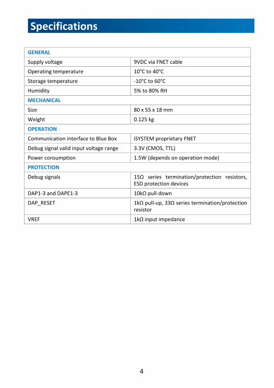
Specifications GENERAL
Supply voltage 9VDC via FNET cable
Operating temperature 10°C to 40°C
Storage temperature -10°C to 60°C
Humidity 5% to 80% RH
MECHANICAL
Size 80 x 55 x 18 mm
Weight 0.125 kg
OPERATION Communication interface to Blue Box iSYSTEM proprietary FNET
Debug signal valid input voltage range 3.3V (CMOS, TTL)
Power consumption 1.5W (depends on operation mode)
PROTECTION Debug signals 15Ω series termination/protection resistors,
ESD protection devices
DAP1-3 and DAPE1-3 10kΩ pull-down
DAP_RESET 1kΩ pull-up, 33Ω series termination/protection resistor
VREF 1kΩ input impedance

5
Operation Device overview
Device description The front side features:
A – 10-pin DAP connector, with the following pinout:
Signal Direction
Signal Description
Signal Pin Pin Signal Signal
description Signal
Direction
IN Reference
Voltage VREF 1 2 DAP1 DAP data pin IN/OUT
Ground GND 3 4 DAP0 DAP clock OUT
Ground GND 5 6 DAP2 Optional
2nd Data Pin IN/OUT
Not
Connected NC 7 8 DAP3
Optional 3rd Data Pin
IN/OUT
Ground GND 9 10 RESET Target Reset Pin OUT
Signal direction definition: OUT - output from the Active Probe to the target microcontroller IN - input to the Active Probe from the target microcontroller
B – 10-pin DAPE connector, with the following pinout:
Signal Direction
Signal Description
Signal Pin Pin Signal Signal
description Signal
Direction
IN Reference
Voltage VREF 1 2 DAP1 DAP data pin IN/OUT
Ground GND 3 4 DAP0 DAP clock OUT
Ground GND 5 6 DAP2 Optional
2nd Data Pin IN/OUT
Not
Connected NC 7 8 DAP3
Optional 3rd Data Pin
IN/OUT
Ground GND 9 10 NC Not Connected
6
Target connector is 10-pin 1.27mm double row connector, for example Samtec FTSH-105-01-L-DV or Samtec FTSH-105-01-L-DV-K (with keying shroud). The rear side features:
C – FNET Micro connector, which connects the Active Probe to the Blue Box (for example the iC5700) through the FNET Micro cable delivered along the Active Probe.
The top side features:
D – The indicator light provides the status of the Active Probe as follows:
o Permanently green - Powered On
o Blinking green – Establishing connection with the Blue Box
o Permanently blue – Ready for use
When powering on the system, switch the iC5700 on before powering on the target system; when powering down the system, power off the target before powering off the iC5700! Use only original iSYSTEM accessories for powering and connecting with the iC5700. Consult with iSYSTEM before attempting to use any other accessory.
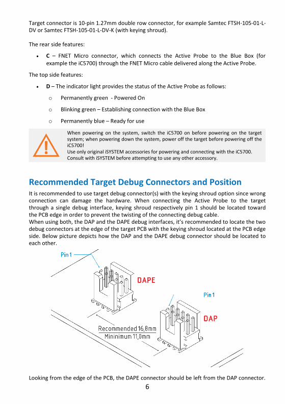
Recommended Target Debug Connectors and Position It is recommended to use target debug connector(s) with the keying shroud option since wrong connection can damage the hardware. When connecting the Active Probe to the target through a single debug interface, keying shroud respectively pin 1 should be located toward the PCB edge in order to prevent the twisting of the connecting debug cable. When using both, the DAP and the DAPE debug interfaces, it’s recommended to locate the two debug connectors at the edge of the target PCB with the keying shroud located at the PCB edge side. Below picture depicts how the DAP and the DAPE debug connector should be located to each other.
Looking from the edge of the PCB, the DAPE connector should be left from the DAP connector.

7
Connectors must be at least 11.0 mm apart while the recommended distance is 16.8 mm. This yields debug cables, connecting the Active Probe to the target, running in parallel without any twisting.
Active Probe and iC5700 Connecting Guidelines
Always start by connecting the iC5700 GND and the target GND using grounding wire delivered along the iC5700.
If the grounding wire is not connected, the ground potential difference between the BlueBox™ hardware and the target can exceed well over 1000V even before any of the devices are powered up. This voltage difference is discharged over the BlueBox™ hardware and the target system, leading to the possible destruction of electronic components within the BlueBox™ hardware, the target or both.
Connect the iC5700 Power Supply to the main outlet and the iC5700 Connect the iC5700 to the PC via the Ethernet or the USB 3.0 cable Connect Active Probe to the iC5700 FNET Port trough the FNET Micro Cable delivered
along the Active Probe. If longer cable than 1m is required (for example when debugging ECU in a car with a very limited space), optional 3 m and 5 m FNET Micro cables are available from iSYSTEM.
Although it looks similar to the HDMI interface, the FNET Port is not compatible with HDMI or any HDMI accessories.
Connecting iSYSTEM hardware to the HDMI devices will damage the hardware and will render the iSYSTEM hardware warranty void.
The Active Probe can be connected to the target in two configurations.
Aurix microcontrollers can have one DAP interface only, through which the on-chip debug module and the MCDS trace module can be accessed. In this case connect 10-cm ribbon cable delivered along the Active Probe to the Active Probe DAP connector and to the target DAP connector.
Newer Aurix devices can have two DAP ports, one named DAP, through which again the on-chip debug module and the MCDS trace module can be accessed, and a second one named DAPE, through which the on-chip MCDS trace module can be

8
accessed. The DAPE port has been introduced to increase the bandwidth of the trace channel toward the debugger. With these devices, the DAP port is used to access the on-chip debug module and the DAPE port to access the MCDS trace module to achieve maximum possible trace port bandwidth. In this case, connect the 10-cm ribbon cable, delivered along the Active Probe, to the Active Probe DAP connector and to the target DAP connector. Next, connect the 2nd 10-cm ribbon cable, delivered along the Active Probe, to the Active Probe DAPE connector and to the target DAPE connector.
When powering on the system, switch the iC5700 on before powering on the target system; when powering down the system, power off the target before powering off the iC5700! Use only original iSYSTEM accessories for powering and connecting with the iC5700. Consult with iSYSTEM before attempting to use any other accessory.
Operating the Active Probe at 160 MHz DAP clock
When using the Active Probe in conjunction with the DAP clock exceeding 100 MHz, connection to the target microcontroller is critical. Have in mind that the period is only 6.25 ns at 160 MHz clock, which is maximum DAP frequency. Maximum signal integrity has to be ensured between the Active Probe and the DAP/DAPE port of the target microcontroller.
For the DAP operation at frequencies higher than 100 MHz the following must be considered:
Target PCB guidelines:
- Physical DAP/DAPE connector must be located as close as possible to the microcontroller
- DAP signals from the microcontroller to the physical DAP/DAPE connector must be routed as short as possible
- No vias should be used if possible or at least keep them at minimum
- Lines must be impedance matched (all should have the same length)
- Stubs on these lines are forbidden
Connection guidelines:
- Solely 10-cm ribbon cables provided by iSYSTEM should be used to connect the Active Probe to the target
- No additional connectors, adapters or cables between the target DAP/DAPE connector and the Active Probe are allowed
Disregarding these guidelines will most likely result in Active Probe not running at high DAP frequencies!
9
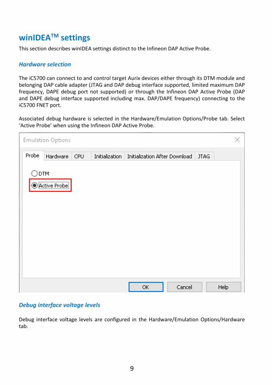
winIDEATM settings This section describes winIDEA settings distinct to the Infineon DAP Active Probe.
Hardware selection The iC5700 can connect to and control target Aurix devices either through its DTM module and belonging DAP cable adapter (JTAG and DAP debug interface supported, limited maximum DAP frequency, DAPE debug port not supported) or through the Infineon DAP Active Probe (DAP and DAPE debug interface supported including max. DAP/DAPE frequency) connecting to the iC5700 FNET port. Associated debug hardware is selected in the Hardware/Emulation Options/Probe tab. Select ‘Active Probe’ when using the Infineon DAP Active Probe.
Debug interface voltage levels Debug interface voltage levels are configured in the Hardware/Emulation Options/Hardware tab.

10
When the VREF signal (pin 10) is 3.3 V or less, select interface signals to be powered from the Active Probe and enter the Vref voltage in the according combo box on the right. When the target supplies 5V to the VREF signal (pin 10), make sure ‘Vref’ option is selected under ‘Debug I/O levels’ setting.
DAP Clock The Active Probe supports DAP interface operation or symultaneous DAP and DAPE interface operation. DAP interface is used per default. DAP (2-pin DAP with single data line) or DAP2 (3-pin DAP2 with two data lines) operation mode can be selected and DAP frequency set. When setting freqeuncy, do not exceed the maximum DAP frequency of the target microcontroller which also depends on the microcontroller configuration. Double check that the 'DAPE' check box is unchecked in this case. For symultanoues DAP and DAPE operation, check the 'DAPE' check box. Likewise for the DAP interface, select DAPE operation mode type and set the DAPE frequency.

11
Other, more general Tricore related settings are described within winIDEA on-lin help.
12
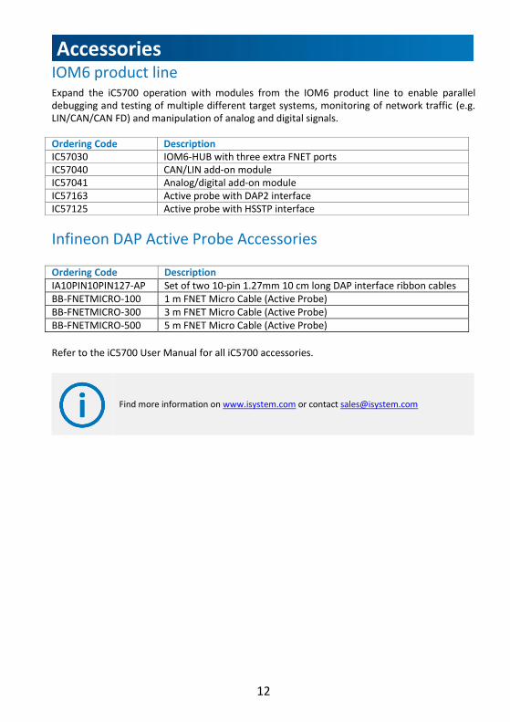
Accessories IOM6 product line Expand the iC5700 operation with modules from the IOM6 product line to enable parallel debugging and testing of multiple different target systems, monitoring of network traffic (e.g. LIN/CAN/CAN FD) and manipulation of analog and digital signals. Ordering Code Description IC57030 IOM6-HUB with three extra FNET ports IC57040 CAN/LIN add-on module IC57041 Analog/digital add-on module IC57163 Active probe with DAP2 interface IC57125 Active probe with HSSTP interface
Infineon DAP Active Probe Accessories Ordering Code Description IA10PIN10PIN127-AP Set of two 10-pin 1.27mm 10 cm long DAP interface ribbon cables BB-FNETMICRO-100 1 m FNET Micro Cable (Active Probe) BB-FNETMICRO-300 3 m FNET Micro Cable (Active Probe) BB-FNETMICRO-500 5 m FNET Micro Cable (Active Probe)
Refer to the iC5700 User Manual for all iC5700 accessories.
Find more information on www.isystem.com or contact [email protected]

13
Technical support
To reach for technical support please visit www.isystem.com/support. iSYSTEM has made every effort to ensure the accuracy and reliability of the information provided in this document at the time of publishing. While iSYSTEM reserves the right to make changes to its products and/or the specifications detailed herein, it does not make any representations or commitments to update this document. iSYSTEM. All rights reserved.