industrialit 800xa - control and i/o s800 i/o 020 923r4101 5 table of contents about this book 0.1...
TRANSCRIPT

IndustrialIT800xA - Control and I/O
S800 I/OVersion 4.1
General Information and Installation


IndustrialIT800xA - Control and I/O
S800 I/OVersion 4.1
General Information and Installation

NOTICEThe information in this document is subject to change without notice and should not beconstrued as a commitment by ABB. ABB assumes no responsibility for any errors thatmay appear in this document.
In no event shall ABB be liable for direct, indirect, special, incidental or consequentialdamages of any nature or kind arising from the use of this document, nor shall ABB beliable for incidental or consequential damages arising from use of any software or hard-ware described in this document.
This document and parts thereof must not be reproduced or copied without written per-mission from ABB, and the contents thereof must not be imparted to a third party nor usedfor any unauthorized purpose.
The software or hardware described in this document is furnished under a license andmay be used, copied, or disclosed only in accordance with the terms of such license.
This product meets the requirements specified in EMC Directive 89/336/EEC and in LowVoltage Directive 72/23/EEC.
Copyright © 2003 - 2005 by ABB. All rights reserved. Release: June 2005Document number: 3BSE 020 923R4101
TRADEMARKSRegistrations and trademarks used in this document include:
Windows Registered trademark of Microsoft Corporation.
Industrial IT Trademark of ABB.
Advant Registered trademark of ABB.
Advant Fieldbus Trademark of ABB.
PROFIBUS Registered trademark of Profibus International (P.I.)
PROFIBUS-DP Registered trademark of Profibus International (P.I.)
HART Registered trademark of HART Communication Foundation.

TABLE OF CONTENTS
About This Book0.1 General ......................................................................................................................15
0.2 Use of Warning, Caution, Information, and Tip Icons ..............................................16
0.3 Terminology...............................................................................................................17
0.4 Applicable Specifications ..........................................................................................18
0.5 Related Documentation .............................................................................................19
Section 1 - Introduction1.1 Product Overview ......................................................................................................23
1.2 Product Scope ............................................................................................................29
1.2.1 ModuleBus ..................................................................................................30
1.2.2 CI801 Fieldbus Communication Interface ..................................................32
1.2.3 CI810/CI810A/CI810B Fieldbus Communication Interface ......................32
1.2.4 CI820 Fieldbus Communication Interface ..................................................33
1.2.5 TB815 Interconnection Unit .......................................................................33
1.2.6 CI830 Fieldbus Communication Interface ..................................................33
1.2.7 CI840 Fieldbus Communication Interface ..................................................33
1.2.8 TB810/TB811 ModuleBus Optical Port......................................................34
1.2.9 TB842 ModuleBus Port ..............................................................................34
1.2.10 TB820 ModuleBus Modem.......................................................................38
1.2.11 TB840/TB840A ModuleBus Modem and TU841 Module Termination Unit .................................................................................40
1.2.12 Module Termination Units ........................................................................44
1.2.13 I/O Modules ..............................................................................................44
1.2.14 S800 I/O Modules .....................................................................................44
1.2.15 S800L I/O Modules...................................................................................44
3BSE 020 923R4101 5

Table of Contents
1.2.16 Power Supply ............................................................................................ 45
1.2.17 G3 Compliant Modules............................................................................. 46
1.2.18 Example of Enclosure Configurations ...................................................... 48
1.2.19 Support for External Intrinsic Safety System ........................................... 49
1.2.20 Support for External HART Communication ........................................... 50
1.2.21 Redundancy .............................................................................................. 50
1.2.21.1 Redundancy Functionality .................................................... 52
Section 2 - Installation2.1 Site Planning ............................................................................................................. 56
2.1.1 Site Selection and Preparation .................................................................... 56
2.1.2 Environmental Considerations.................................................................... 56
2.1.2.1 General.................................................................................... 56
2.1.2.2 Temperature ............................................................................ 57
2.1.2.3 Vibration ................................................................................. 58
2.1.3 Electromagnetic Compatibility and CE Marking ....................................... 58
2.1.4 Layout of I/O Stations................................................................................. 58
2.1.4.1 I/O Station with S800 I/O ....................................................... 58
2.1.4.2 Mounting Procedures S800L I/O............................................ 59
2.1.4.3 Redundant FCI Installation AF100......................................... 64
2.1.4.4 Redundant FCI Installation Profibus ...................................... 65
2.1.4.5 ModuleBus Extension (Electrical).......................................... 66
2.1.4.6 Optical ModuleBus Expansion Single Configuration ............ 70
2.1.4.7 Optical ModuleBus Expansion Redundant Configuration ..... 75
2.1.4.8 I/O Module Installation........................................................... 75
2.1.5 Grounding ................................................................................................... 79
2.1.5.1 General.................................................................................... 79
2.1.5.2 Protective Earth (PE) .............................................................. 80
2.1.5.3 Grounding of Signals and Voltage Supply.............................. 80
2.1.6 Signal Cable Considerations ....................................................................... 81
2.1.6.1 Recommendations for Signal and Process Cable ................... 81
2.1.7 Power Requirements ................................................................................... 83
2.1.7.1 General.................................................................................... 83
6 3BSE 020 923R4101

Table of Contents
2.1.7.2 A.C. Supply .............................................................................84
2.1.7.3 D.C. Supply .............................................................................84
2.1.8 Hazardous Applications ..............................................................................84
2.1.9 High Voltage Switch-gear Applications......................................................84
2.1.10 Lightning Strike Protection .......................................................................84
2.1.11 Mounting Dimensions ...............................................................................85
2.1.11.1 Overhead Clearances.............................................................85
2.1.11.2 Rear and Side Clearance........................................................86
2.1.11.3 Clearances within an Enclosure ............................................87
2.2 Installation Procedures ..............................................................................................88
2.2.1 Safety Regulations ......................................................................................88
2.2.1.1 Personnel Safety......................................................................89
2.2.1.2 Equipment Safety ....................................................................89
2.2.2 Grounding in Enclosures.............................................................................90
2.2.2.1 General ....................................................................................90
2.2.2.2 Protective Earth.......................................................................90
2.2.2.3 Ground Line ............................................................................90
2.2.2.4 Grounding of Process Cable Shields.......................................90
2.2.2.5 Grounding of Communication Cable Shields .........................90
2.2.2.6 Grounding of Process Signals .................................................91
2.2.2.7 Grounding of Additional Equipment ......................................91
2.2.3 Cable Routing in Enclosures .......................................................................92
2.2.4 Power Connection .......................................................................................92
2.2.4.1 General ....................................................................................92
2.2.5 I/O Station with S800 I/O............................................................................93
2.2.5.1 Assembly.................................................................................93
2.2.5.2 Electric Installation .................................................................94
2.2.5.3 Address Setting .......................................................................95
2.2.5.4 Check of the External Wiring..................................................96
2.2.6 Checklists ....................................................................................................97
2.2.6.1 Grounding Philosophy, Ground Plane System........................97
2.2.6.2 Process Cabling, Shielding, Grounding, Max. Length............98
3BSE 020 923R4101 73BSE 020 923R4101 7
Table of Contents
2.2.6.3 Power Supply.......................................................................... 99
2.2.6.4 Lightning Protection ............................................................. 100
2.2.6.5 MTU, I/O Module................................................................. 100
2.2.6.6 Cabinet, Internal Cables........................................................ 101
2.2.6.7 Environmental Data .............................................................. 102
2.2.6.8 Airborne Contaminants......................................................... 102
2.2.6.9 Miscellaneous ....................................................................... 103
2.2.6.10 External Cables ................................................................... 103
2.2.7 Final Procedure Before Start-up ............................................................... 103
2.3 Start-up and Shut-down Procedures........................................................................ 104
2.3.1 Start-up Procedures ................................................................................... 104
2.3.1.1 Safety Regulations ................................................................ 104
2.3.1.2 Controller and I/O................................................................. 104
2.3.1.3 Security Guidelines............................................................... 104
2.3.2 Shut-down Procedures .............................................................................. 105
2.3.2.1 Safety Regulations ................................................................ 105
2.3.2.2 Emergency Shut Down ......................................................... 105
2.3.2.3 Safety Shut Down ................................................................. 105
2.3.2.4 Manual Stop .......................................................................... 106
2.4 Product Verification ................................................................................................ 107
2.4.1 General...................................................................................................... 107
2.4.1.1 Check of Process Input/Output Systems............................... 107
2.4.1.2 Input Signals ......................................................................... 108
2.4.1.3 Output Signals....................................................................... 110
2.4.2 Final Check ............................................................................................... 112
Section 3 - Configuration3.1 Design Considerations ............................................................................................ 113
3.1.1 I/O Station Layout Hardware Configuration Guidelines .......................... 113
3.1.2 Redundant FCIs for Advant Fieldbus 100 ................................................ 118
3.1.3 Redundant FCIs and I/O Modules for PROFIBUS .................................. 118
3.1.4 I/O Clusters ............................................................................................... 120
3.1.5 CI801/CI810/CI820/CI830/CI840 FCI..................................................... 124
8 3BSE 020 923R4101

Table of Contents
3.1.6 TB820 and TB840/TB840A ModuleBus Modem.....................................125
3.1.6.1 Cluster Address Switch .........................................................126
3.1.6.2 Optical ModuleBus Connections ..........................................127
3.1.6.3 Power Supply Connections ...................................................130
3.1.7 TB825 Optical Media Converter...............................................................133
3.1.7.1 Optical ModuleBus Connections ..........................................133
3.1.7.2 Power Supply Connections ...................................................135
3.1.7.3 Optical Fiber Connection ......................................................135
3.1.7.4 Calculation of Maximum Optical ModuleBus Configuration135
3.2 Power Supply System..............................................................................................137
3.3 Powering S800 I/O System .....................................................................................137
3.4 Powering Field Equipment ......................................................................................137
3.4.1 Interference ...............................................................................................137
3.4.2 Short-circuit at the output..........................................................................137
3.4.3 Sectioning the field equipment..................................................................138
3.4.4 Cable protection ........................................................................................138
3.4.5 Connection alternatives .............................................................................138
3.5 Power Supply Load Calculation ..............................................................................141
3.5.1 Appropriate Hardware...............................................................................141
3.5.2 Guidelines .................................................................................................141
3.6 Heat Dissipation ......................................................................................................142
3.6.1 Cabinet Ventilation....................................................................................142
3.6.2 Heat Dissipation Permitted in Cabinets ....................................................142
3.6.3 Calculation of Heat Generated in a Cabinet..............................................142
3.7 Maintenance and Repair ..........................................................................................143
3.8 Expansion Considerations .......................................................................................143
3.9 Power Supply Requirements ...................................................................................144
3.9.1 Power Supply for DO880..........................................................................144
3.10 Power and Cooling ................................................................................................145
3.10.1 Calculation of 24 V d.c. Power Consumption.........................................149
Section 4 - Operation4.1 Operating Overview ................................................................................................151
3BSE 020 923R4101 93BSE 020 923R4101 9

Table of Contents
Section 5 - Maintenance5.1 Preventive Maintenance .......................................................................................... 153
5.2 Hardware Indicators ................................................................................................ 153
5.2.1 Color ......................................................................................................... 153
5.2.2 Location .................................................................................................... 154
5.2.3 Identification ............................................................................................. 155
5.3 Error Messages........................................................................................................ 155
5.4 Fault Finding and User Repair ................................................................................ 156
5.4.1 Introduction............................................................................................... 156
5.4.2 Diagnostics and Fault Indications............................................................. 156
5.4.2.1 LED indicators on modules: ................................................. 156
5.4.3 List of General Fault Finding Procedures and Hints ................................ 156
5.4.3.1 Location of Malfunction ....................................................... 156
5.4.3.2 External Factors .................................................................... 157
5.4.3.3 Safety at Start/Stop ............................................................... 157
5.4.3.4 Check of Non-redundant Power Supply ............................... 157
5.4.3.5 Check of Redundant Power Supply ...................................... 158
5.4.4 User Repair ............................................................................................... 158
5.4.4.1 I/O Module Replacement...................................................... 158
5.4.4.2 Power Supply Module Replacement..................................... 159
5.4.4.3 Communication Module Replacement ................................. 160
Appendix A - General SpecificationsA.1 Standards and Approvals........................................................................................ 163
A.1.1 Electrical Safety Standards and Approvals .............................................. 163
A.1.2 Hazardous Classified Locations............................................................... 164
A.1.3 CE-marking.............................................................................................. 164
A.2 Transport and Storage Conditions .......................................................................... 165
A.3 Climatic operating conditions ................................................................................ 166
A.4 Mechanical operating conditions ........................................................................... 166
A.5 EMC ....................................................................................................................... 167
A.5.1 Overvoltage Categories............................................................................ 168
10 3BSE 020 923R4101

Table of Contents
A.6 Equipment Class and Insulation Voltages...............................................................169
A.6.1 Overvoltage Categories According to IEC 60664-1 ................................169
A.6.2 Equipment Class.......................................................................................169
A.6.3 Insulation Voltage.....................................................................................169
A.6.4 Insulation Test Voltage .............................................................................169
Appendix B - SpecificationsB.1 SD821/SD822/SD823 Power Supply Modules, 24 V d.c.......................................171
B.1.1 Key Features .............................................................................................171
B.1.2 Equipment Class .......................................................................................171
B.1.3 Ingress Protection .....................................................................................172
B.1.4 Power Supply Units Types SD821 / 822 / 823 - Description ...................176
B.1.5 Insulation of Power Supply Units (PSU)..................................................177
B.1.6 Fuses and Protective Devices ...................................................................178
B.1.7 Technical Data ..........................................................................................178
B.1.8 Connection Diagram.................................................................................181
B.2 SS822 Voting Unit - (for Redundant Power Supply)..............................................182
B.2.1 Redundant Power Supply Configurations ................................................182
B.3 SS823 Power Voter Unit - (for Redundant power Supply).....................................186
B.3.1 Redundant Power Supply Configurations ................................................186
B.4 TB805/TB806 ModuleBus Cable Adapter-Out/In..................................................191
B.4.1 Features.....................................................................................................191
B.4.2 Description ...............................................................................................191
B.4.3 Technical Data ..........................................................................................193
B.4.4 Block Diagram TB805 .............................................................................194
B.4.5 Block Diagram TB806 .............................................................................194
B.5 TB807 ModuleBus Terminator ...............................................................................195
B.5.1 Features.....................................................................................................195
B.5.2 Description ...............................................................................................195
B.5.3 Technical Data ..........................................................................................196
B.5.4 Block Diagram TB807 .............................................................................197
B.6 TB810/TB811 ModuleBus Optical Port .................................................................198
B.6.1 Features.....................................................................................................198
3BSE 020 923R4101 113BSE 020 923R4101 11

Table of Contents
B.6.2 Description TB810 ................................................................................... 198
B.6.3 Description TB811 ................................................................................... 198
B.6.4 Technical Data.......................................................................................... 199
B.6.5 Connections.............................................................................................. 200
B.6.6 Opto Cable for TB810 according to HP................................................... 200
B.6.7 Opto Cable for TB811 according to HP................................................... 201
B.6.8 Block Diagram TB810/TB811 ................................................................. 201
B.7 TB820 ModuleBus Modem.................................................................................... 202
B.7.1 Features .................................................................................................... 202
B.7.2 Description ............................................................................................... 202
B.7.3 Technical Data.......................................................................................... 204
B.7.4 Connections ............................................................................................. 207
B.7.5 Opto Cable according to HP .................................................................... 208
B.7.6 Block Diagram TB820 ............................................................................. 209
B.8 TB825 Optical Media Converter ............................................................................ 210
B.8.1 Features .................................................................................................... 210
B.8.2 Description ............................................................................................... 210
B.8.3 Technical Data.......................................................................................... 211
B.8.4 Opto Connection ...................................................................................... 213
B.8.4.1 Local Optical Cable.............................................................. 213
B.8.4.2 Field Optical Cable .............................................................. 213
B.8.5 Block Diagram TB825 ............................................................................. 214
B.9 TB840/TB840A ModuleBus Modem..................................................................... 215
B.9.1 Features .................................................................................................... 215
B.9.2 Description ............................................................................................... 215
B.9.3 Technical Data.......................................................................................... 217
B.9.4 Connections.............................................................................................. 219
B.9.5 Opto Cable according to HP .................................................................... 219
B.9.6 Connection Diagram TB840/TB840A ..................................................... 221
B.10 TB842 ModuleBus Optical Port ........................................................................... 222
B.10.1 Features .................................................................................................. 222
B.10.2 Description TB842 ................................................................................. 222
12 3BSE 020 923R4101

Table of Contents
B.10.3 Technical Data ........................................................................................223
B.10.4 Connections ............................................................................................224
B.10.5 Opto Cable for TB842 according to HP .................................................224
B.10.6 Block Diagram TB842 ...........................................................................225
B.11 TB845/TB846 ModuleBus Cable Adapter-Out/In................................................226
B.11.1 Features...................................................................................................226
B.11.2 Description..............................................................................................226
B.11.3 Technical Data ........................................................................................228
B.11.4 Block Diagram TB845............................................................................229
B.11.5 Block Diagram TB846............................................................................229
B.12 TU840, MTU for Redundant TB840/TB840A with Dual ModuleBus ................................................................................................230
B.12.1 Features...................................................................................................230
B.12.2 Description .............................................................................................230
B.12.3 Technical Data ........................................................................................231
B.12.4 Dimensions .............................................................................................232
B.12.5 Connections ............................................................................................233
B.12.6 Block Diagram TU840 ...........................................................................234
B.13 TU841, MTU for Redundant TB840/TB840A with Single ModuleBus ..............235
B.13.1 Features...................................................................................................235
B.13.2 Description .............................................................................................235
B.13.3 Technical Data ........................................................................................236
B.13.4 Dimensions .............................................................................................237
B.13.5 Connections ............................................................................................238
B.13.6 Block Diagram TU841 ...........................................................................239
Appendix C - Power UpC.1 Power Up on S800 I/O............................................................................................241
INDEX ........................................................................................................................251
3BSE 020 923R4101 133BSE 020 923R4101 13

Table of Contents
14 3BSE 020 923R4101

About This Book
0.1 GeneralThis book provides a general description of the S800 I/O and reference information about equipment common to all types of installations, for example power supplies and ModuleBus components. It provides overall instructions for site planning and installation, start-up and shutdown procedures, and information regarding capacity and performance. This book is not intended to be the sole source of instruction for the S800 I/O system.
This section provides introductory and background information including guidelines how to find information in the manual related documentation.
Section 1, Introduction provides a product and functional overview.
Section 2, Installation guides in installation of the I/O system including:
• Guidelines for planning the installation of the product.
• Information how to set up the equipment. It includes safety regulations, handling and unpacking instructions, inspection and assembly procedures, cable routing and connections, setup procedures, etc. Common instructions as well as instructions directed to specific subsystem are given. Activities prior to power up are described.
• Shut-down procedures. In addition to safety regulations, the basic shut down procedures are given. You should know how to shut-down the product if initial power up has problems.
• Start-up procedures. In the set-up section the conditions and the preparation for start are discussed, and here you can find basic power up procedures, such as, how to apply power to and initialize the I/O system.
• Product Verification. Initial determination that the I/O is functional.
3BSE 020 923R4101 15

Use of Warning, Caution, Information, and Tip Icons About This Book
Section 3, Configuration will give you the information needed to obtain the desired function. The main information is structured as follow:
• Design considerations and guidelines are given.
• Capacity and performance.
Section 4, Operation discusses the different start modes and operating modes of the I/O.
Section 5, Maintenance focus is on fault finding supported by built in diagnostics and use of system status displays in operator station and LEDs on I/O hardware units.
0.2 Use of Warning, Caution, Information, and Tip IconsThis publication includes Warning, Caution, and Information where appropriate to point out safety related or other important information. It also includes Tip to point out useful hints to the reader. The corresponding symbols should be interpreted as follows:
Those people involved in system engineering should attend the applicable system engineering or maintenance courses offered by ABB Automation University.
Electrical warning icon indicates the presence of a hazard which could result in electrical shock.
Warning icon indicates the presence of a hazard which could result in personal injury.
Caution icon indicates important information or warning related to the concept discussed in the text. It might indicate the presence of a hazard which could result in corruption of software or damage to equipment/property.
Information icon alerts the reader to pertinent facts and conditions.
Tip icon indicates advice on, for example, how to design your project or how to use a certain function
16 3BSE 020 923R4101

About This Book Terminology
Although Warning hazards are related to personal injury, and Caution hazards are associated with equipment or property damage, it should be understood that operation of damaged equipment could, under certain operational conditions, result in degraded process performance leading to personal injury or death. Therefore, comply fully with all Warning and Caution notices.
0.3 TerminologyThe following is a list of terms associated with S800 that you should be familiar with. The list contains terms and abbreviations that are unique to ABB or have a usage or definition that is different from standard industry usage.
Term Description
AF 100 Advant Fieldbus 100 is the communications bus between the I/O stations and the Advant Controllers. (FCI to CI52x)
Base cluster Consists of single or redundant ModuleBus masters plus I/O modules connected directly to the ModuleBus master.
FCI The Fieldbus Communication Interface (FCI) device contains the interface to the fieldbus (for example PROFIBUS or AF 100).
G3 compliant The module withstand more severe environmental conditions according to ISA-S71.04.
I/O cluster An extension of the I/O Station’s ModuleBus connected to the ModuleBus master by fiber optic connections. Up to 12 I/O devices per cluster.
I/O device A complete I/O device consists of one MTU and one I/O module.
I/O module Is an active, electronic and signal conditioning unit. Can be a part of an I/O device or a S800L I/O module.
I/O station An I/O station consists of one or two FCI(s), 1-7 I/O clusters and up to 24 I/O devices.
I.S. Intrinsic Safety is a protection technique to prevent explosion in hazardous areas of a process plant.
3BSE 020 923R4101 17

Applicable Specifications About This Book
0.4 Applicable Specifications
This product meets the requirements specified in EMC Directive 89/336/EEC and in Low Voltage Directive 72/23/EEC.
ModuleBus Is an incremental, electrical or optical, bus for interconnection of I/O devices.
ModuleBus master ModuleBus master can be a controller (AC 800M) or a FCI. A ModuleBus master contains a ModuleBus interface and power regulators. The FCI module can manage 24 I/O devices and the controller up to 96 I/O modules (up to 12 directly and to the others in 1 to 7 I/O clusters).
(ModuleBus) Extension cable
Is used when extending the electrical ModuleBus (within the max. 2 meters).
MTU The Module Termination Unit is a passive base unit containing process terminals and a part of the ModuleBus.
OSP Outputs Set as Predetermined. A user configurable action on an output module when communications is lost to the FCI or Controller.
PROFIBUS-DP PROFIBUS-DP is a fieldbus standard.
PROFIBUS-DPV1 PROFIBUS-DPV1 is a fieldbus standard.
RTD Resistance Temperature Detector.
SOE Sequence of events. Time stamping of status changes for digital inputs.
TC Thermocouples
Term Description
18 3BSE 020 923R4101

About This Book Related Documentation
0.5 Related Documentation
Title Description
S800 I/O Modules and Termination Units Describes the I/O modules and termination units in the S800 I/O system.
S800 I/O Modules and Termination Units with Intrinsic Safety Interface
Describes I/O modules and termination units with I.S. interface in the S800 I/O system.
S800 I/O Fieldbus Communication Interface for Advant Fieldbus 100 User’s Guide
Describes the AF100 FCI in the S800 I/O system.
S800 I/O Fieldbus Communication Interface for PROFIBUS-DP/DPV1
Describes the PROFIBUS-DP FCI in the S800 I/O system.
S800 I/O PROFIBUS FCIMemory Maps for CI801
Describes the memory mapping on PROFIBUS for the S800 I/O system in CI801.
S800 I/O PROFIBUS FCIMemory Maps for CI830
Describes the memory mapping on PROFIBUS for the S800 I/O system in CI830.
S800 I/O PROFIBUS FCIMemory Maps for CI840
Describes the memory mapping on PROFIBUS for the S800 I/O system in CI840.
Advant Fieldbus 100 User’s Guide Describes the equipment and contains information required to install and commission AF100.
3BSE 020 923R4101 19

Related Documentation About This Book
20 3BSE 020 923R4101

Section 1 Introduction
The S800 I/O is distributed modular I/O which communicates with numerous controllers over a Advant Fieldbus 100 (AF 100), PROFIBUS-DP/DPV1 or directly. The S800 I/O provides easy installation of the I/O modules and process cabling. It is highly modularized and flexible so that I/O modules can be combined to suit many applications. The S800 I/O can be mounted in many configurations to fit most requirements both in single or fully redundant applications.
Figure 1-1 S800 I/O Fieldbus Communication Interface with an I/O Module on Compact and Extended MTUs and an S800L Module
3BSE 020 923R4101 21

Section 1 Introduction
Figure 1-2 S800 I/O Station Overview
Controller
Fieldbus
Scope of this book
Optical
Optical ModuleBus Modem
I/O ModuleFCI
ModuleBus
ModuleBus Optical Port
Base Cluster
I/O Station
Electrical ModuleBus
Base Cluster
I/O Cluster
I/O Cluster
22 3BSE 020 923R4101
Section 1 Introduction Product Overview
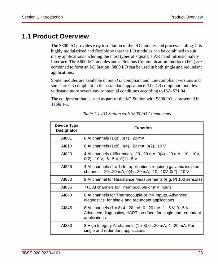
1.1 Product OverviewThe S800 I/O provides easy installation of the I/O modules and process cabling. It is highly modularized and flexible so that the I/O modules can be combined to suit many applications including the most types of signals, HART and Intrinsic Safety Interface. The S800 I/O modules and a Fieldbus Communication Interface (FCI) are combined to form an I/O Station. S800 I/O can be used in both single and redundant applications.
Some modules are available in both G3 compliant and non-compliant versions and some are G3 compliant in their standard appearance. The G3 compliant modules withstand more severe environmental conditions according to ISA-S71.04.
The equipment that is used as part of the I/O Station with S800 I/O is presented in Table 1-1.
Table 1-1 I/O Station with S800 I/O Components
Device Type Designator
Function
AI801 8 AI channels (1x8), 0(4)...20 mA
AI810 8 AI channels (1x8), 0(4)...20 mA, 0(2)...10 V
AI820 4 AI channels (differential), -20...20 mA, 0(4)...20 mA, -10...10V, 0(2)...10 V, -5...5 V, 0(1)...5 V
AI825 4 AI channels (4 x 1) for applications requiring galvanic isolated channels, -20...20 mA, 0(4)...20 mA, -10...10V, 0(2)...10 V
AI830 8 AI channel for Resistance Measurements (e.g. Pt 100 sensors)
AI835 7+1 AI channels for Thermocouple or mV Inputs
AI843 8 AI channels for Thermocouple or mV Inputs. Advanced diagnostics, for single and redundant applications.
AI845 8 AI channels (1 x 8) 4...20 mA, 0...20 mA, 1...5 V, 0...5 V. Advanced diagnostics, HART interface, for single and redundant applications.
AI880 8 High Integrity AI channels (1 x 8) 0...20 mA, 4...20 mA. For single and redundant applications
3BSE 020 923R4101 23
Product Overview Section 1 Introduction
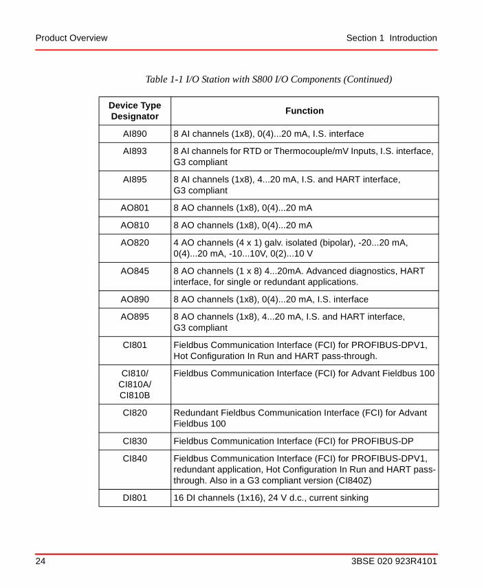
AI890 8 AI channels (1x8), 0(4)...20 mA, I.S. interface
AI893 8 AI channels for RTD or Thermocouple/mV Inputs, I.S. interface, G3 compliant
AI895 8 AI channels (1x8), 4...20 mA, I.S. and HART interface, G3 compliant
AO801 8 AO channels (1x8), 0(4)...20 mA
AO810 8 AO channels (1x8), 0(4)...20 mA
AO820 4 AO channels (4 x 1) galv. isolated (bipolar), -20...20 mA, 0(4)...20 mA, -10...10V, 0(2)...10 V
AO845 8 AO channels (1 x 8) 4...20mA. Advanced diagnostics, HART interface, for single or redundant applications.
AO890 8 AO channels (1x8), 0(4)...20 mA, I.S. interface
AO895 8 AO channels (1x8), 4...20 mA, I.S. and HART interface, G3 compliant
CI801 Fieldbus Communication Interface (FCI) for PROFIBUS-DPV1, Hot Configuration In Run and HART pass-through.
CI810/CI810A/CI810B
Fieldbus Communication Interface (FCI) for Advant Fieldbus 100
CI820 Redundant Fieldbus Communication Interface (FCI) for Advant Fieldbus 100
CI830 Fieldbus Communication Interface (FCI) for PROFIBUS-DP
CI840 Fieldbus Communication Interface (FCI) for PROFIBUS-DPV1, redundant application, Hot Configuration In Run and HART pass-through. Also in a G3 compliant version (CI840Z)
DI801 16 DI channels (1x16), 24 V d.c., current sinking
Table 1-1 I/O Station with S800 I/O Components (Continued)
Device Type Designator
Function
24 3BSE 020 923R4101

Section 1 Introduction Product Overview
DI802 8 DI channels (1x8), 120 V d.c., current sinking
DI803 8 DI channels (1x8), 230 V d.c., current sinking
DI810 16 DI channels (2x8), 24 V d.c., current sinking. Also in a G3 compliant version (DI810Z)
DI811 16 DI channels (2x8), 48 V d.c., current sinking
DI814 16 DI channels (2x8), 24 V d.c. current sourcing
DI820 8 galvanic isolated DI channels (8x1), 120 V a.c./d.c., current sinking. Also in a G3 compliant version (DI820Z).
DI821 8 galvanic isolated DI channels, (8x1) 230 V a.c./d.c., current sinking. Also in a G3 compliant version (DI821).
DI825 8 galvanic isolated DI channels, (8x1) 125 V d.c. with sequence of event (SOE) handling
DI830 16 DI channels (2x8) 24 V d.c. with sequence of event (SOE) handling, current sinking
DI831 16 DI channels (2x8) 48 V d.c. with sequence of event (SOE) handling, current sinking
DI840 16 DI channels (2x8) 24 V d.c. with sequence of event (SOE) handling. Advanced diagnostics, for single or redundant applications.
DI880 16 High Integrity DI channels (1 x 16) 24 V d.c. with sequence of event (SOE) handling.For single and redundant applications.
DI885 8 DI channels, (1x8) 24/48 V d.c. with sequence of event (SOE) handling, current sinking
DI890 8 DI channels (8x1), I.S. interface
DO801 16 DO channels (1x16), 24 V d.c., 0.5 A, current sourcing
Table 1-1 I/O Station with S800 I/O Components (Continued)
Device Type Designator
Function
3BSE 020 923R4101 25

Product Overview Section 1 Introduction
DO802 8 DO channels (1x8), 24-110 V d.c./250 V a.c., relay normally open
DO810 16 DO channels (2x8), 24 V d.c., 0.5 A, current sourcing. Also in a G3 compliant version (DO810Z)
DO814 16 DO channels (2x8), 24 V d.c., 0.5 A, current sinking
DO815 8 DO channels (2x4), 24 V d.c., 2 A, current sourcing. Also in a G3 compliant version (DO815Z).
DO820 8 DO channels (8x1), Relay, 250 V, 3 A a.c. normally open. Also in a G3 compliant version (DO820Z).
DO821 8 DO channels (8x1), Relay, 250 V, 3 A a.c. normally closed
DO840 16 DO channels (16x1), Relay, 24 V, 0.5 A a.c. with advanced diagnostics, for single or redundant applications.
DO880 16 High Integrity DO channels (1 x 16) 24 V d.c.For single and redundant applications.
DO890 4 channels (4x1), 11 V 40 mA, I.S. interface
DP820 2 channels, pulse count and frequency measurement, maximum 1.5 MHz. Interface for RS422, current, 5V, 12 V or 24 V.
DP840 8 channels, pulse count and frequency measurement, maximum 20 kHz. With advanced diagnostics, for single or redundant applications. Interface for NAMUR, 12 V and 24 V.The input can be read as digital input signals. Also in a G3 compliant version (DP840Z).
SD821 Power supply, 115/230 V a.c. to 24 V d.c. @ 2.5 A
SD822 Power supply, 115/230 V a.c. to 24 V d.c. @ 5.0 A. Also in a G3 compliant version (SD822Z)
SD823 Power supply, 115/230 V a.c. to 24 V d.c. @ 10 A
Table 1-1 I/O Station with S800 I/O Components (Continued)
Device Type Designator
Function
26 3BSE 020 923R4101

Section 1 Introduction Product Overview
SS822 Voting Unit for redundant power supply, 24 V d.c. @ 20.0 A. Also in a G3 compliant version (SS822Z)
SS823 Power Voter with overvoltage protection, 24 V d.c., 20 A
TB805 Cable adaptor out module (electrical ModuleBus). Also in a G3 compliant version (TB805Z)
TB806 Cable adaptor in module (electrical ModuleBus). Also in a G3 compliant version (TB806Z).
TB807 Terminator module for electrical ModuleBus, G3 compliant.
TB810 ModuleBus Optical Port Module 10 Mbit driver, fiber optic connection. Used together with CI810, CI820 and CI830.
TB811 ModuleBus Optical Port Module 5 Mbit driver, fiber optic connection. Used together with CI810, CI820 and CI830.
TB815 ModuleBus Interconnection Unit to redundant FCIs (CI820)
TB820 ModuleBus Modem, fiber optic ModuleBus interface of an I/O cluster. 10 Mbit driver.
TB825 ModuleBus Optical media converter, converts between plastic opto fiber or HCS fiber with Versatile link connectors and glass optical fiber with ST connectors.
TB840/TB840A ModuleBus Modem, fiber optic ModuleBus interface of an I/O cluster. 10 Mbit driver. Redundant application.
TB842 ModuleBus Optical Port Module 10 Mbit driver, fiber optic connection. Used together with CI840.
TB845 Cable adaptor out module (double electrical ModuleBus)
TB846 Cable adaptor in module (double electrical ModuleBus)
TC501V150 Cable terminator for AF 100 twisted pairs, 150 ohms
TC505 Connector: AF 100 Trunk Tap to FCI
Table 1-1 I/O Station with S800 I/O Components (Continued)
Device Type Designator
Function
3BSE 020 923R4101 27

Product Overview Section 1 Introduction
TK801V003 Cable, ModuleBus Extension, 300 mm (11.8"), G3 compliant
TK801V006 Cable, ModuleBus Extension, 600 mm (23.6"), G3 compliant
TK801V012 Cable, ModuleBus Extension, 1.2 m (47.25"), G3 compliant
TK811V015 Cable, Optical ModuleBus Extension, 1.5 m (59"), duplex, plastic
TK811V050 Cable, Optical ModuleBus Extension, 5 m (16’), duplex, plastic
TK811V150 Cable, Optical ModuleBus Extension, 15 m (50’), duplex, plastic
TK812V015 Cable, Optical ModuleBus Extension, 1.5 m simplex, plastic
TK812V050 Cable, Optical ModuleBus Extension, 5 m simplex, plastic
TK812V150 Cable, Optical ModuleBus Extension, 15 m simplex, plastic
TU805 Terminal Unit 2 x 18 terminals, 50 V. Used to enable 2- and 3-wire connections on DI801 and DO801. The Terminal Unit is mounted direct on DI801 or DO801.
TU810 Compact MTU, 3x8 + 2x3 terminals, 50 V. Also in a G3 compliant version (TU810Z)
TU811 Compact MTU, 2x8 terminals, 250 V. Also in a G3 compliant version (TU811Z).
TU812 Compact MTU, 25 pin D-sub Connector for field connection, 50 V
TU814 Compact MTU, Crimp Snap-in Connector for field connection50 V.
TU830 Extended MTU, 3x16 + 2x4 terminals, 50 V
TU831 Extended MTU, 8x2 terminals, 250 V
TU835 Extended MTU, 4x2 groups + 2x4 power terminals, 50 V, individually fused per channel
TU836 Extended MTU, 2x4 groups + 2x6 power terminals, 250 V, individually fused per channel
Table 1-1 I/O Station with S800 I/O Components (Continued)
Device Type Designator
Function
28 3BSE 020 923R4101

Section 1 Introduction Product Scope
1.2 Product ScopeThe S800 I/O is a modular I/O system. The modular system allows for easy configuration of the I/O type and size.
TU837 Extended MTU, 2x4 groups + 2x6 power return terminals,250 V, fused
TU838 Extended MTU, 2x4 groups + 2x4 power return terminals, 50 V, fused
TU840 MTU for redundant TB840, dual ModuleBus
TU841 MTU for redundant TB840, single ModuleBus
TU842 16 channel, 50 V, horizontal dual MTU for redundant I/O
TU843 16 channel, 50 V, vertical dual MTU for redundant I/O
TU844 8 channel, 50 V, horizontal dual MTU for redundant I/O
TU845 8 channel, 50 V, vertical dual MTU for redundant I/O
TU846 MTU for redundant CI840, dual ModuleBus
TU847 MTU for redundant CI840, single ModuleBus. Also in a G3 compliant version (TU847Z).
TU890 Compact MTU for I.S. interface Module, 50 V. For use in I.S. applications.
TU891 Compact MTU for I.S. interface Module, 50 V. Not for use in I.S. applications. Also in a G3 compliant version (TU891Z).
TY801 Shunt stick for current or voltage signals together with AI845 or AI880 and TU844 or TU845, 2 x 125 Ω.
TY804 Shunt stick for NAMUR signals together with DP840 and TU844 or TU845, 1 kΩ
Table 1-1 I/O Station with S800 I/O Components (Continued)
Device Type Designator
Function
3BSE 020 923R4101 29

ModuleBus Section 1 Introduction
An S800 I/O Station can consist of a base cluster and up to 7 additional I/O clusters. The base cluster, consists of a single or redundant Fieldbus Communication Interface (FCI) module and up to 12 single I/O modules or 6 pairs of redundant I/O modules. I/O clusters 1 to 7 consist of a ModuleBus Modem and up to 12 I/O modules. I/O clusters 1 to 7 are connected to the FCI through a fiber optic expansion of the ModuleBus. An S800 I/O Station can have up to 24 I/O modules. This means that an I/O Station can have a maximum of 384 digital channels or a maximum of 192 analog channels.
Each I/O cluster can be divided in groups using ModuleBus extension cables between the groups. The maximum length of the electrical ModuleBus of an I/O cluster is 2.5 meters (8.2 ft.) including extension cables. The factory made extension cables which plug into the cable adaptors are available in lengths of 0.3, 0.6 and 1.2 m (1, 2 and 4 ft.). The maximum length of the optical ModuleBus expansion is dependent on the number of ModuleBus Modems. The maximum length between any two clusters is 15m (50ft.) with plastic fiber and 200 m (667ft) with HCS glass fiber. Factory made optical duplex or simplex cables (plastic fiber) are available in lengths of 1.5, 5 and 15 m (5, 16.7 or 50 ft.).
1.2.1 ModuleBus
Each S800 I/O module is installed on a Module Termination Unit (MTU). The first MTU with its I/O module or S800L module connects to the ModuleBus master or a cluster’s ModuleBus Modem and then each of the remaining MTUs or S800L modules connect to the previous MTU or S800L module.
An ModuleBus master communicates with its I/O modules over the ModuleBus. The ModuleBus can be divided into 8 clusters, one base cluster and up to 7 I/O cluster. The base cluster consists of the ModuleBus master (single or redundant) and I/O modules (single or redundant). Additional I/O clusters (1 to 7) consist of a ModuleBus Modem and I/O modules. The ModuleBus Modems are connected via optical cables to an optional ModuleBus Optical Port module on the ModuleBus master.
Within a cluster the ModuleBus is made up of increments that are integrated into each MTU or S800L module. The ModuleBus master and ModuleBus Modems have a ModuleBus outlet connector to connect to an MTU or a S800L module. An MTU and S800L module have a bus inlet and a bus outlet connector. By adding, on the DIN rail, an MTU or a S800L module to a ModuleBus master or a ModuleBus
30 3BSE 020 923R4101

Section 1 Introduction ModuleBus
Modem, the bus is automatically expanded up to a maximum of 12 single or 6 redundant MTUs or S800L modules. Unique position codes are automatically assigned to each MTU or S800L module as the bus is expanded. An inserted S800 module is assigned the unique position identity of its MTU. Through the incremental bus design the physical size of an S800 I/O installation is directly proportional to the number of installed MTUs or S800L modules.
The S800 I/O modules can be inserted and removed from MTUs without disturbing system operation. The physical lock, which locks an I/O module to its MTU, allows I/O module removal only when the lock is in its unlock position. The locking mechanism also acts as a logic lock so that an I/O module is only operational when the lock is in the locked position. If the lock is in its unlocked position, output channels are de-energized and I/O modules can be inserted/removed without need to remove system or field power.
The MTUs are totally passive units with all active circuitry allocated to the I/O module. The ModuleBus requires a terminator to be installed after the last MTU or S800L module of a cluster.
Figure 1-3 shows a typical base cluster in an I/O station with single I/O modules and single FCI connected to PROFIBUS or Advant Fieldbus 100.
Figure 1-3 Typical I/O Station Base Cluster with S800 I/O, Single or Redundant FCI
2.5 meters (8.2 feet) maximum
1 2 3 4 5 6 7 8 9 11 12 13 14 1510 16
Sta
tus
S 1 2 3 4 5 6 7 8 9 10 11 12 13 14 15 16
3BSE 020 923R4101 31

CI801 Fieldbus Communication Interface Section 1 Introduction
Figure 1-4 shows a typical base cluster in an I/O station with single I/O modules and redundant FCI connected to Advant Fieldbus 100.
Redundant I/O modules and redundant FCI connected to PROFIBUS are shown in Figure 1-20.
1.2.2 CI801 Fieldbus Communication Interface
The CI801 Fieldbus Communication Interface (FCI) module is a configurable communication interface which performs operations such as signal processing, gathering of various supervision information, OSP handling, Hot Configuration In Run, HART pass-through and configuration of I/O modules. The FCI connects to the controller by way of the PROFIBUS-DPV1 fieldbus.
Please refer to specifications in S800 I/O Fieldbus Communication Interface for PROFIBUS-DP/DPV1 for more information.
1.2.3 CI810/CI810A/CI810B Fieldbus Communication Interface
The CI810/CI810A/CI810B Fieldbus Communication Interface (FCI) module is a configurable communication interface which performs operations such as signal processing, gathering of various supervision information, OSP handling and configuration of re-inserted I/O modules. The FCI connects to the controller by way of the Advant Fieldbus 100 (AF 100) twisted pair segment. The FCI supports redundant media configurations.
Please refer to specifications in S800 I/O Fieldbus Communication Interface for Advant Fieldbus 100 for more information.
Figure 1-4 I/O Station Base Cluster with Redundant FCIs to S800 I/O for AF100
2.5 meters (8.2 feet) maximum
1 2 3 4 5 6 7 8 9 11 12 13 14 1510 16S
tatu
s
S1 2 3 4 5 6 7 8 9 10 11 12 13 14 15 16
32 3BSE 020 923R4101

Section 1 Introduction CI820 Fieldbus Communication Interface
1.2.4 CI820 Fieldbus Communication Interface
The CI820 Fieldbus Communication Interface (FCI) module is a configurable communication interface which performs operations such as signal processing, gathering of various supervision information, OSP handling and configuration of re-inserted I/O modules. The FCI connects to the controller by way of the Advant Fieldbus 100 (AF 100) twisted pair segment. The FCI supports redundant fieldbus communication interface.
Please refer to specifications in S800 I/O Fieldbus Communication Interface for Advant Fieldbus 100 User’s Guide for more information.
1.2.5 TB815 Interconnection Unit
The TB815 Interconnection Unit is used with redundant CI820 FCIs to provide an interface to the ModuleBus (electrical and optical) and service port connections. All signals between the redundant FCIs such as AF 100 signals and control signals are routed through the TB815 and it also provides the termination of the electrical ModuleBus.
Please refer to specifications in S800 I/O Fieldbus Communication Interface for Advant Fieldbus 100 User’s Guide for more information.
1.2.6 CI830 Fieldbus Communication Interface
The CI830 Fieldbus Communication Interface (FCI) module is a configurable communication interface which performs operations such as signal processing, gathering of various supervision information, OSP handling and configuration of I/O modules. The FCI connects to the controller by way of the PROFIBUS-DP fieldbus.
Please refer to specifications in S800 I/O Fieldbus Communication Interface for PROFIBUS-DP/DPV1 for more information.
1.2.7 CI840 Fieldbus Communication Interface
The CI840 Fieldbus Communication Interface (FCI) module is a configurable communication interface which performs operations such as signal processing, gathering of various supervision information, OSP handling, Hot Configuration In Run, HART pass-through and configuration of I/O modules. CI840 is designed for
3BSE 020 923R4101 33

TB810/TB811 ModuleBus Optical Port Section 1 Introduction
redundant applications. The FCI connects to the controller by way of the PROFIBUS-DPV1 fieldbus.
Please refer to specifications in S800 I/O Fieldbus Communication Interface for PROFIBUS-DP/DPV1 for more information.
1.2.8 TB810/TB811 ModuleBus Optical Port
The TB810/TB811 Optical ModuleBus Port is used with the CI810 or CI830 FCI or the TB815 Interconnection Unit to provide an interface for the Optical ModuleBus expansion. The TB810/TB811 has connectors for fiber optic connections and a connection to the communication interface module.
TB810 is used with TB820 and ABB Drives equipment with 10 Mbit driver.
TB811 is used with ABB Drives equipment with 5 Mbit driver. Figure 1-5 shows the TB810/TB811 installed in the CI810 FCI.
1.2.9 TB842 ModuleBus Port
The TB842 optical port is used for optical extension of the ModuleBus. The TB842 Optical ModuleBus Port is used with the CI801 or the CI840 redundant FCI. The TB842 module can be connected to CI801 through TB806 or redundant CI840 through TB806 and TU847 (single I/O) or through TB846 and TU846 (redundant
Figure 1-5 TB810/TB811 Optical ModuleBus Port installed in CI810A FCI
STN. ADDR.
SBSA
L-L+ L+
L-
SH
+
-Tx
RxSH
+
-
SHSH
CI810A
012
9
75
38
4 6
012
9
75
38
4 6
x 10
x 1
AF100
LED Status Indicators
Tx RxSWX.X/Y
21TB810/TB811Optical ModuleBus Port
34 3BSE 020 923R4101

Section 1 Introduction TB842 ModuleBus Port
I/O), see Figure 1-6, Figure 1-7 and Figure 1-8. The TB842 has two connectors for fiber optic connections and a connection to the communication interface module.
Figure 1-6 TB842 Optical ModuleBus Port mounted on TB806 module for connection to TU847
CI840 CI840
1
TB806
TB842
FR
PRIM
PRx/Tx
DUAL
FR
PRIM
PRx/Tx
DUAL
TU847
3BSE 020 923R4101 35

TB842 ModuleBus Port Section 1 Introduction
Figure 1-7 TB842 Optical ModuleBus Port mounted on TB846 for connection to TU846
36 3BSE 020 923R4101

Section 1 Introduction TB842 ModuleBus Port
Figure 1-8 TB842 Optical ModuleBus Port mounted on TB806 module for connection to CI801
1
Power Supply
AddressSwitch #1
AddressSwitch #2PROFIBUS-DP
Connector
LED StatusIndicators
ModuleBusInterfaceConnector
TB806TB842
3BSE 020 923R4101 37

TB820 ModuleBus Modem Section 1 Introduction
1.2.10 TB820 ModuleBus Modem
The TB820 ModuleBus Modem is a fiber optic interface to the ModuleBus. The ModuleBus Modem has an electrical and an optical interface which are logically the same bus. A maximum of 12 I/O modules can be connected to the electrical ModuleBus and up to seven clusters can be connected to the fiber optic ModuleBus. The fiber optic interface is intended for local distribution of I/O clusters and where more then 12 I/O modules are required in an I/O Station.
38 3BSE 020 923R4101

Section 1 Introduction TB820 ModuleBus Modem
The TB820 ModuleBus Modem has a rotary switch that selects its cluster number, 1 to 7, on the optical ModuleBus. Figure 1-9 shows the layout of TB820.
The ModuleBus Modem communicates with the FCI or Controller via the Optical ModuleBus.
The TB820 ModuleBus Modem provides 24 V d.c. current limited (from the source) and an isolated, current limited 5 V dc power to the cluster’s I/O modules by way of the electrical ModuleBus connection. One power source (single or redundant 24 V d.c.) can be connected to the power terminals (L+ & L-). Redundant power supply can be supervised via inputs SA and SB.
Figure 1-9 TB820 ModuleBus Modem
12
75
34 6 Cluster Address
Switch
Power SupplyConnections
LED Status Indicators
DIN RailElectrical ModuleBusInterface Connector
(Address 4 shown)
Optical ModuleBusInterface Connector
CLUSTER
SB
F R
ORx2ORx1P
TB820 V2
ERx
X4 X5RxTxRx Tx
Redundant PowerSupervision
L
L+
SA
3BSE 020 923R4101 39

TB840/TB840A ModuleBus Modem and TU841 Module Termination Unit Section 1 Introduction
Please refer to specifications in Appendix B, Specificationsfor more information.
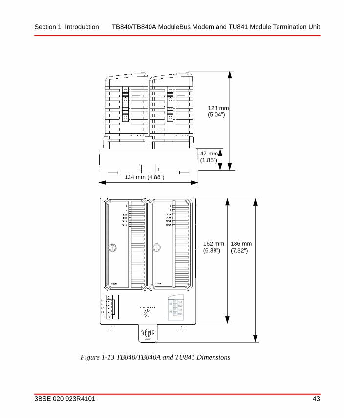
1.2.11 TB840/TB840A ModuleBus Modem and TU841 Module Termination Unit
The TB840/TB840A ModuleBus Modem is a fiber optic interface to the Optical ModuleBus. TB840/TB840A is used in redundancy configurations where each module is connected to different optical ModuleBus lines, but connected to the same electrical ModuleBus.
The ModuleBus Modem has an electrical and an optical ModuleBus interface which are logically the same bus. A maximum of 12 I/O modules can be connected to the electrical ModuleBus and up to seven clusters can be connected to the fiber optic ModuleBus. The fiber optic interface is intended for local distribution of I/O clusters and where more then 12 I/O modules are required in an I/O Station.
Figure 1-10 TB820 ModuleBus Modem Dimensions
CLUSTER
BSA
L-
L+ +-
F R
ORx2ORx1
P
TB820
12
75
34 6
ERx
170
mm
(6.
7”)
58 mm (2.3”) 122 mm (4.8”)
SB
LL+SA
40 3BSE 020 923R4101

Section 1 Introduction TB840/TB840A ModuleBus Modem and TU841 Module Termination Unit
The cluster address sets by a rotary switch on the Termination Unit TU841 in range 1 to 7. Figure 1-11 shows the layout of TB840.
The TB840/TB840A ModuleBus Modem provides 24 V d.c. short circuit proof (from the source) and an isolated, short circuit proof 5 V dc power to the cluster’s I/O modules by way of the electrical ModuleBus connection. One power source (single or redundant 24 V d.c.) can be connected to the power terminals (L+ & L-). Redundant power supply can be supervised via inputs SA and SB.
The rotary switch and the connector for power supply is located on TU841.
Figure 1-11 TB840 ModuleBus Modem
TB840
SP
Rx1Rx2
ERx1ERx2
3BSE 020 923R4101 41

TB840/TB840A ModuleBus Modem and TU841 Module Termination Unit Section 1 Introduction
Figure 1-12 TU841 Module Termination Unit for TB840/TB840A
CLUSTER ADDR.
42 3BSE 020 923R4101
Section 1 Introduction TB840/TB840A ModuleBus Modem and TU841 Module Termination Unit
Figure 1-13 TB840/TB840A and TU841 Dimensions
124 mm (4.88”)
128 mm
47 mm
162 mm
(1.85”)
(5.04”)
(6.38”)186 mm(7.32”)
3BSE 020 923R4101 43

Module Termination Units Section 1 Introduction
Please refer to specifications in Appendix B, Specifications for more information.
1.2.12 Module Termination Units
The Module Termination Units (MTU) are passive base units used to house the S800 I/O modules. They contain the process wiring terminals.
Please refer to specifications in S800 I/O Modules and Termination Units and S800 I/O Modules and Termination Units with Intrinsic Safety Interface for more information.
1.2.13 I/O Modules
There are two different types of I/O modules; S800 modules and S800L modules.
S800 modules are designed to be put into a MTU.
S800L modules are designed to be put direct on a standard DIN rail and contain also process connections and part of the ModuleBus.
1.2.14 S800 I/O Modules
The I/O modules have open ventilated plastic enclosures. On the front of each I/O module there are three LEDs (FAULT, RUN and WARNING) indicating the module status and digital I/O modules have a status LED for each channel, some even two. One additional LED (OSP) is included on analog output and digital output modules.
I/O modules may be replaced in a fully operational I/O station. Mechanical keying on modules and MTUs protect I/O modules from being inserted in positions where they could be damaged by excessive voltage or current. An electronic type designation ID in each module keeps the I/O module from being taken into operation by the ModuleBus master, if a module’s ID does not match the configured module type definition in the data base.
1.2.15 S800L I/O Modules
The I/O modules have open vertical plastic enclosures and a bottom of sheet-metal. On the front of each I/O modules there is a LED (STATUS) indicating the module status (run or fault) and digital I/O modules have a status LED for each channel.
44 3BSE 020 923R4101

Section 1 Introduction Power Supply
Please refer to specifications in S800 I/O Modules and Termination Units and S800 I/O Modules and Termination Units with Intrinsic Safety Interface for more information.
1.2.16 Power Supply
The SD821, SD822 and SD823 are switch-mode power supply units which convert the mains voltage to 24 volts d.c. These power supplies can be utilized for non-redundant and redundant applications. Redundant applications requires a diode voting unit SS822.
Please refer to specifications in Appendix B.1, SD821/SD822/SD823 Power Supply Modules, 24 V d.c.for more information.
The S800 I/O station can be powered by a single or redundant supply voltage of 24 V d.c., see Figure 1-14 and Figure 1-15. Three power supplies with 115/230 V inputs and 24 V d.c. outputs are available to supply the I/O station and its field circuits. The SD821 Power Supply provides 2.5 A at 24 V d.c., the SD822 Power Supply provides 5 A at 24 V d.c. and SD823 Power Supply provides 10 A at 24 V d.c. See Power Supply Connections on page 130 for details.
Figure 1-14 Installation Using Single Power Supply Unit
BA
24 V
24 V power supply
I/O modules
FCI I/O stationor ModuleBus Modem
PowerSupply
3BSE 020 923R4101 45

G3 Compliant Modules Section 1 Introduction
The ModuleBus master and ModuleBus Modem are able to supervise the redundant voltage supply. The supervision function is individually configurable for power supervision of each I/O station.
1.2.17 G3 Compliant Modules
Some modules are available in both G3 compliant and non-compliant versions and some are G3 compliant in their standard appearance.
G3 is a severity level in the standard ISA-S71.04 Environmental Conditions for Process Measurement and Control Systems: Airborne Contaminants, for further information about the environment turn to the standard ISA-S71.04.
When the module is available in both versions, the G3 compliant version is marked with a “Z” on the front, see Figure 1-16. The G3 compliant modules are the same as the non-compliant S800 I/O modules in all other aspects.
Figure 1-15 Installation Using Redundant Power Supply Units
24 V d.c. power supply
Supervision 24V A, 24V B
I/O modules
I/O station
FCI
BA
24 V
or ModuleBus Modem
PowerSupply
B
Power
A
Supply Voting Unit
46 3BSE 020 923R4101

Section 1 Introduction G3 Compliant Modules
During transport, storage and installation special caution must be taken;
• Dividable connectors/terminals must not be left unconnected/open in G3 environment if the are intended to be used later.
• Module must not be stored in G3 environment due to unprotected connectors/terminals, also valid for modules in packaging.
Figure 1-16 G3 Compliant Module DI810Z
67
8
9
10
11
12
13
14
15
16
F
R
W
1
2
3
4
5
DI81024V Z
3BSE 020 923R4101 47

Example of Enclosure Configurations Section 1 Introduction
1.2.18 Example of Enclosure Configurations
In Figure 1-17 a layout example are shown for an I/O station in an RE820 cabinet which could house the I/O station with power supplies for the I/O system as well as for the field powering, and space for marshalling terminals.
Figure 1-17 RE820 Cabinet with 12 I/O Modules and Redundant Station Power Supplies
POW
FC
I
POW
800 mm (31.5")
100
0 m
m (
39.4
")
48 3BSE 020 923R4101

Section 1 Introduction Support for External Intrinsic Safety System
1.2.19 Support for External Intrinsic Safety System
Beside S800 I/O modules with Intrinsic Safety Interfaces, Intrinsic Safety Systems can be connected to the S800 I/O.
Intrinsic Safety System from Pepperl+Fuchs Elcon (manufacturer outside ABB) is supported via S800 I/O module and a special MTU.
Supported Intrinsic Safety System is the HiD Series 2000.
The S800 I/O modules are connected via MTU TU812, a standard cable and a specific adapter board, one for each I/O module types.
For further information refer to Elcon Instruments Manuals.
The following I/O modules are supported:
AI810, AO810, DI810 and DO810.
See Figure 1-18 for an example of a connection between S800 I/O and Intrinsic Safety System.
Figure 1-18 Example of Connection between S800 I/O and Intrinsic Safety System from Pepperl+Fuchs Elcon
S800 I/0
Intrinsic Safety System
3BSE 020 923R4101 49

Support for External HART Communication Section 1 Introduction
1.2.20 Support for External HART Communication
Beside S800 I/O modules with HART interface, Pepperl+Fuchs Elcon provides a HART protocol connection to I/O modules integrated with the Intrinsic Safety System, see Figure 1-19.
For further information refer to Pepperl+Fuchs Elcon.
1.2.21 Redundancy
Figure 1-2 shows the basic construction of I/O Stations without any redundancy. To increase the up-time, a number of component can be set up with redundancy:
• Power Supply
• I/O Module
• Fieldbus Communication Interface (FCI)
• Fieldbus
• Electrical ModuleBus
Figure 1-19 Example of Connection between S800 I/O and Intrinsic Safety System from Pepperl+Fuchs Elcon and HART Multiplexer Interface from HART
To PCRS485S800 I/O
Intrinsic Safety System
HART Multiplexer Connection
50 3BSE 020 923R4101

Section 1 Introduction Redundancy
An example of a system using redundancy for all these components is shown in Figure 1-20.
It is not necessary to implement redundancy on all components, but there are some dependencies:
• Redundant power supply requires no other redundancy.
Figure 1-20 I/O Station Overview with Maximum Redundancy and Additional Single I/O Modules
Redundant
Fieldbus
I/O ModuleFCIModuleBus Electrical ModuleBusOptical Port
Optical
Optical ModuleBus Modem
ModuleBus
I/O Cluster
I/O Cluster
Controller
3BSE 020 923R4101 51

Redundancy Section 1 Introduction
• Redundant Advant Fieldbus 100 requires no other redundancy.
• Redundant PROFIBUS requires redundant FCIs
• Redundant FCI requires:– redundant fieldbus
• Redundant I/O Module (only in base cluster and on PROFIBUS) requires:– double electrical ModuleBus– redundant FCI– redundant fieldbus
1.2.21.1 Redundancy Functionality
Fieldbus Communication Interface (FCI)
When using redundant FCI, one is primary and one is secondary. The FCI will diagnose itself, and when the primary FCI fails it will hand over to the secondary FCI.
If using redundant FCI and redundant electrical ModuleBuses only on PROFIBUS, the primary FCI will control both electrical ModuleBuses. When the primary FCI fails, the secondary FCI will take control of both electrical ModuleBuses.
Input Modules
When using redundant input modules, all reading is done from the primary input module. The input module will diagnose itself, and when the primary input module fails the reading will be done from the secondary input module.
The secondary AI module is checked for error status at a lower cycle rate than the primary.
Analogue Output Modules
When using redundant AO modules, half the output current is generated from each AO module. The AO module will diagnose itself, and when one fails, it disconnects and a direct communication between the two redundant AO modules will ensure that the second AO module quickly doubles its output current.
52 3BSE 020 923R4101

Section 1 Introduction Redundancy
Digital Output Module
When using redundant DO modules, they both work parallel to each other. They give the same output.
When one DO module fails it will give output signals set to low. The DO module that still work will override by setting active signals to high.
3BSE 020 923R4101 53

Redundancy Section 1 Introduction
54 3BSE 020 923R4101

Section 2 Installation
This section contains guidelines for planning the installation of the S800 I/O equipment.
This section does not give the complete list of measures to be taken with respect to environment and other conditions on site. The equipment should be adapted to the actual application by thorough system definition and design.
Since each system is designed to meet a specific requirement, there is no standard configuration that describes every system. Therefore, certain areas of the following instructions are meant only as a guide for planning a specific installation. However, some of the information covers specific requirements for proper system and equipment operation, and is not subject to modification.
All information given in this section relates to standard equipment.
For installation of Advant Fieldbus 100 and Advant Fieldbus 100 modems, see the Advant Fieldbus 100 User’s Guide.
For installation of PROFIBUS see relevant documentation.
3BSE 020 923R4101 55

Site Planning Section 2 Installation
2.1 Site Planning
2.1.1 Site Selection and Preparation
When planning an S800 I/O installation, please consider the following:
• Surrounding environment and atmosphere.
• The temperature in the room where the equipment is to be located. This should include an estimation of the resulting temperature rise with respect to the power dissipation from the planned equipment.
• Proximity of the equipment to the process.
• Size of the cabinets to accommodate all the required equipment.
• Minimum distances from a cabinet to walls and ceiling to obtain satisfactory results from different aspects.
• Ease of access for moving equipment in and out of area.
• Free space in front of cabinets. Also consider the need of space to fully open a cabinet door either left hand or right hand hinged.
• Spare area for future expansion of the system.
• Grounding by an effective plane of copper bars.
• Cable routing with respect to installation rules.
• Availability of power and other utilities.
The following sections examine some of these factors in detail and provide recommendations and requirements as necessary.
2.1.2 Environmental Considerations
2.1.2.1 General
S800 I/O equipment can be installed in a designated control room, or located in the process area when housed in a suitable enclosure. The S800 I/O is designed for a demanding industrial environment.
56 3BSE 020 923R4101

Section 2 Installation Environmental Considerations
2.1.2.2 Temperature
I/O Module Factors
The maximum ambient air temperature around S800 modules is 55°C (131°F) for I/O modules mounted on Extended MTUs on vertical or horizontal orientated DIN-rails, or I/O modules mounted on compact MTUs on horizontal oriented DIN-rails. I/O modules mounted in Compact MTUs or S800L modules on a vertical DIN-rail allows operation at 40°C (104°F).
The maximum ambient air temperature around S800L modules is 55°C (131°F) for I/O modules mounted on horizontal orientated DIN-rails. It is 40°C (104°F) for I/O modules mounted on vertical oriented DIN-rails.
The ambient temperature de rating which applies for vertical DIN rail and Compact MTUs is due to the reduced air flow through an I/O module due to the orientation.
The different hardware modules in the S800 I/O have different outputs of heat. Accurate calculation of the heat produced by the system requires knowledge of the modules and the work cycle. Power supplies with regulated outputs are highly recommended to minimize heat in cabinets. Use of such devices will reduce the power loss of resistive loads and current outputs, for example, digital inputs and analog outputs. Please refer to Power and Cooling on page 145 for more information.
Cabinets Factors
The temperature within cabinets and in the surrounding environment and atmosphere must be considered, especially when using sealed cabinets (IP65/IP54) or tropicalized cabinets (IP41) with considerable equipment and outside ambient temperatures at levels approaching 40°C (104°F). The frequency of faults is estimated to double for each 20°C (36°F) increase in temperature. Thus, it is important to maintain as low ambient temperature outside the cabinets (typical operating range 10 - 40°C (50 - 104°F)) as possible where the equipment is installed. Design considerations are given in Heat Dissipation Permitted in Cabinets on page 142.
3BSE 020 923R4101 57

Electromagnetic Compatibility and CE Marking Section 2 Installation
2.1.2.3 Vibration
The cabinets are to be located on a stable floor, wall, deck or supporting structure, free from vibrations.
If the system equipment is installed in a control room adjacent to large machinery such as shakers or large presses, where frequent major vibrations occur, shock absorbers or an isolation pad may be required to protect the system equipment. Shock absorbers normally protect the equipment from sustained low level vibrations (vibrations that are perceptible, but not excessive). If vibrations or shock is a major problem, more extreme measures must be considered to alleviate the problem, such as fasten the MTUs with extra screws.
2.1.3 Electromagnetic Compatibility and CE Marking
Grounding, cable selection and cable routing must be considered for electromagnetic interference-free operation. Planning considerations are discussed in the following sections. Instructions for implementing these plans are provided in Installation Procedures on page 88.
The S800 I/O meets requirements specified in EMC Directive 89/336/EEC. You should request CE marking and compliance when ordering the equipment.
2.1.4 Layout of I/O Stations
2.1.4.1 I/O Station with S800 I/O
The S800 I/O is mounted on a standard DIN-rail according to EN 50022 NS35/7,5. The DIN-rail is mounted in a cabinet or on an enclosure wall to a metal sheet with fastening screws every 100 mm to ensure a good chassis ground connection in the cabinet or an open rack. The ModuleBus master, ModuleBus Modem, MTUs and S800L I/O modules are mounted to the DIN rail. In environments with major vibrations, the MTUs shall also be screwed on the metal sheet. The FCI, ModuleBus Modem and MTUs have a snap locking device that attaches it to the mounting rail.
It is possible to mount the FCI, ModuleBus Modem, MTUs and S800L I/O modules both vertically and horizontally.
To mount the FCI, ModuleBus Modem or MTU, place it on the top edge of theDIN rail, release the rail latch with a flat blade screw driver and snap the bottom
58 3BSE 020 923R4101

Section 2 Installation Layout of I/O Stations
mechanism into place. When the unit is in place on the DIN rail and in position, take away the screw driver and the rail latch will fix the unit in position on the DIN rail. Release the unit from the DIN rail in a similar way.
S800L module has screw locking device that attaches it to the mounting rail.
2.1.4.2 Mounting Procedures S800L I/O
Use a screwdriver with a 1 mm (0.03 inch) tick flat blade that fits the locking screw. This is the only tool you need for the mounting. See Figure 2-1.
1. Turn the locking device to open position (1) and hook the lip at the rear of the unit onto the DIN rail and snap the unit into position.
2. Turn the screw to the slide position (2). Now you can slide the unit along the rail to desired position and join it to another unit. Make sure that the connector pins and sockets are in line. Do not use excessive force!
3. Turn the screw clockwise to locked position (3). The unit is now locked and has good earth connection to the DIN rail.It is essential that the locking device is in locked position to avoid problems due to vibration and inadequate grounding.
Figure 2-1 Mounting Procedures
1. Open 2. Slide 3. Locked
3BSE 020 923R4101 59

Layout of I/O Stations Section 2 Installation
Figure 2-2 Unlocking the S800L I/O Module
DO801
Turn the screw counterclockwise torelease the locking device
60 3BSE 020 923R4101

Section 2 Installation Layout of I/O Stations
A flat blade screw driver can be used to release the latch to allow easier movement along the DIN rail or removal of the unit (Figure 2-3).
Snapping the FCI, ModuleBus Modem or MTU to the DIN-rail makes contact by a grounding spring with the chassis.
Figure 2-3 MTU Latching System
A
BC
D
E F
A
BC
D
E F
Move up torelease rail latch
GroundClip Spring
DIN-railI/O ModuleLock/Switch
Pry down torelease rail latch
To
Lock
C1 2 3 4 5 6 7 C8 L2+L1+
B1 2 3 4 5 6 7 B8 L2+L1+
A1 2 3 4 5 6 7 A8 L2-L1-
3BSE 020 923R4101 61

Layout of I/O Stations Section 2 Installation
Connection of the MTU, or S800L module, ModuleBus connector to the FCI, ModuleBus Modem, next MTU or S800L module is made by sliding the MTU or the S800L module along the mounting rail and then locking it in place (Figure 2-4).
Figure 2-4 I/O Station Installation Diagram
A
BC
D
E F
A
BC
D
E F
STN. ADDR.
SBSA
L-L+ L+
L-
SH
+
-
F R
T2T1
P
SH
+
-
SH
SH
SERVICE
CI810
012
9
75
38
4 6
012
9
75
38
4 6
x 10
x 1
AF100
A
BC
D
E F
A
BC
D
E F
C1 2 3 4 5 6 7 C8
B1 2 3 4 5 6 7 B8
A1 2 3 4 5 6 7 A8
L1+ L2+
L2-L1-
L2+L1+Tx
Rx
Tx RxSWX.X/Y
21
A1 2 3 4 5 6 7 A8 L2-L1-
B1 2 3 4 5 6 7 B8L1+ L2+
C1 2 3 4 5 6 7 C8 L2+L1+
62 3BSE 020 923R4101

Section 2 Installation Layout of I/O Stations
The MTU and S800L module (locking screw in position) can be disconnected from the FCI, ModuleBus Modem, another MTU or S800L module by using a screw driver and pressing it between the two items.
Figure 2-5 Module Release
A
BC
D
E F
A
BC
D
E FSTN. ADDR.
SBSA
L-L+ L+
L-
SH
+
-
F R
T2T1
P
SH
+
-
SH
SH
SERVICE
CI810
012
9
75
38
4 6
012
9
75
38
4 6
x 10
x 1
AF100
C1 2 3 4 5 6 7 C8
B1 2 3 4 5 6 7 B8
A1 2 3 4 5 6 7 A8
L1+ L2+
L2-L1-
L2+L1+Tx
Rx
Tx RxSWX.X/Y
21
DO801
3BSE 020 923R4101 63
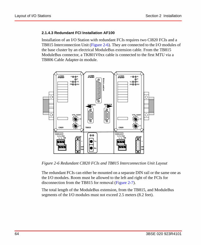
Layout of I/O Stations Section 2 Installation
2.1.4.3 Redundant FCI Installation AF100
Installation of an I/O Station with redundant FCIs requires two CI820 FCIs and a TB815 Interconnection Unit (Figure 2-6). They are connected to the I/O modules of the base cluster by an electrical ModuleBus extension cable. From the TB815 ModuleBus connector, a TK801V0xx cable is connected to the first MTU via a TB806 Cable Adapter-in module.
The redundant FCIs can either be mounted on a separate DIN rail or the same one as the I/O modules. Room must be allowed to the left and right of the FCIs for disconnection from the TB815 for removal (Figure 2-7).
The total length of the ModuleBus extension, from the TB815, and ModuleBus segments of the I/O modules must not exceed 2.5 meters (8.2 feet).
Figure 2-6 Redundant CI820 FCIs and TB815 Interconnection Unit Layout
Tx
Rx
MODULEBUS
SERVICE SERVICE
SBSA
L-L+L+
L-
STN. ADDR
F R
P
CI820
012
9
75
38
4 6
012
9
75
38
4 6
x 10
x 1
T1 T2
PR DU
SBSA
L-L+L+
L-
STN. ADDR
R
P
CI820
012
9
75
38
4 6
012
9
75
38
4 6
x 10
x 1
T2
DU
TB815
F
T1
PR
SWX.X/Y SWX.X/Y
+-
SHSH
AF100
+-
SHSH
AF100
64 3BSE 020 923R4101

Section 2 Installation Layout of I/O Stations
Optical ModuleBus Extension can be connected to the TB815 via the TB810 ModuleBus Optical Port unit for connection of 1 to 7 additional I/O clusters.
2.1.4.4 Redundant FCI Installation Profibus
Installation of an I/O Station with redundant FCIs requires two CI840 FCIs and one TU846 or TU847 (Figure 2-8). They are direct connected to the I/O modules of the base cluster.
TU846 are used with redundant I/O modules and TU847 with single I/O modules.
Figure 2-7 Connection of Redundant FCIs to I/O Modules
Tx
Rx
MODULEBUS
SERVICE SERVICE
SBSA
L-L+ L+
L-
STN. ADDR
F R
P
CI820
012
9
75
38
4 6
012
9
75
38
4 6
x 10
T1 T2
PR DU
SBSA
L-L+ L+
L-
STN. ADDR
R
P
CI820
012
9
75
38
4 6
012
9
75
38
4 6
x 10
x 1
T2DU
TB815
F
T1
PR
TB806
TK801V003(300 mm)
(1 ft.)
A
BC
D
E F
A
BC
D
E F
67
8
910
111213
14
1516
FR
W
1
234
5
24VDI810
C1 2 3 4 5 6 7 C8
B1 2 3 4 5 6 7 B8
A1 2 3 4 5 6 7 A8
L1+ L2+
L2-L1-
L2+L1+
A
BC
D
E F
A
BC
D
E F
67
8
910
111213
14
1516
FR
W
1
234
5
24VDI810
C1 2 3 4 5 6 7 C8
B1 2 3 4 5 6 7 B8
A1 2 3 4 5 6 7 A8
L1+ L2+
L2-L1-
L2+L1+
A
BC
D
E F
A
BC
D
E F
67
8
910
111213
14
1516
FR
W
1
234
5
24VDI810
C1 2 3 4 5 6 7 C8
B1 2 3 4 5 6 7 B8
A1 2 3 4 5 6 7 A8
L1+ L2+
L2-L1-
L2+L1++
-
SHSH
AF100
+
-
SHSH
AF100
x 1
3BSE 020 923R4101 65

Layout of I/O Stations Section 2 Installation
The total length of the electrical ModuleBus, must not exceed 2.5 meters (8.2 feet).
2.1.4.5 ModuleBus Extension (Electrical)
When the next MTU or S800L module is located away from the previous MTU, S800L module, then a TK801V0xx ModuleBus Extension cable must be used. The previous MTU or S800L module will require a TB805 Cable Adapter-out to be plugged into the ModuleBus-out connector. The TK801V0xx cable is then
Figure 2-8 Redundant CI840 FCIs on TU847
CI840
F
PRx/TxPRIMDUAL
R
Address Switches
Serviceports
Connection toElectrical ModuleBus
CI840
F
PRx/TxPRIMDUAL
R
66 3BSE 020 923R4101

Section 2 Installation Layout of I/O Stations
connected to the TB805 adapter. The next MTU will have a TB806 Cable Adapter-in plugged into the ModuleBus-in connector and then connected to the other end of the ModuleBus Extension cable. See Figure 2-9.
In case of redundant I/O two TK801V0xx ModuleBus Extension cables, a Cable Adapter-out TB845 instead of TB805 and a Cable Adapter-in TB846 instead of TB806 are needed. See Figure 2-10.
The TB805/TB806 ModuleBus Cable Adapter-Out/In adapters mount on the DIN-rail. Each has a latch that locks it to the rail. There is also a grounding spring that connects it to the DIN-rail. The latch can be released with a screw driver and the adaptor moved toward or away (for removal) from the MTU or S800L module.
3BSE 020 923R4101 67

Layout of I/O Stations Section 2 Installation
The ModuleBus Extension cable comes in three standard lengths:
• TK801V003 - 300 mm (1 ft.)
• TK801V006 - 600 mm (2 ft.)
• TK801V012 - 1.2 meters (4 ft.).
ModuleBus length must not exceed 2.5 meters (8.2 feet) from FCI, TB815 Interconnection Unit, or ModuleBus Modem to the last MTU or S800L module including extension cables.
Figure 2-9 ModuleBus Extension Cable Connections, single I/O
ABC
D
E F
ABC
D
E F
678910111213141516
FRW
12345
24 VDI810
ABC
D
E F
ABC
D
E F
678910111213141516
FRW
12345
24 VDI810
C1 2 3 4 5 6 7 C8
B1 2 3 4 5 6 7 B8
A1 2 3 4 5 6 7 A8
L1+ L2+
L2-L1-
L2+L1+
TB805
TB806
TK801V003(300 mm)
Latch Release
Male Cable Connector Female Cable
Connector
(1 ft.)A1 2 3 4 5 6 7 A8 L2-L1-
B1 2 3 4 5 6 7 B8L1+ L2+
C1 2 3 4 5 6 7 C8L2+L1+
68 3BSE 020 923R4101

Section 2 Installation Layout of I/O Stations
Figure 2-10 ModuleBus Extension Cable Connections, Redundant I/O
I/O I/OTB846
TB845TB84x TB84x
TK801V0xx
3BSE 020 923R4101 69

Layout of I/O Stations Section 2 Installation
2.1.4.6 Optical ModuleBus Expansion Single Configuration
The FCI (Fieldbus Communication Interface) provides fiber optic expansion of the ModuleBus for up to 7 additional I/O clusters or to drive equipment. The TB810/TB811 ModuleBus Optical Port must be inserted in to the CI810 or CI830 FCI or TB815 Interconnect unit (redundant CI820) to provide optical ModuleBus expansion. See Figure 2-11 for location of the TB810/TB811 on the CI810/CI830 FCI and Figure 2-12 for location in the TB815 Interconnection Unit.
The TB842 ModuleBus Optical Port must be connected to CI840 via TB806 or TB846 and TU846 or TU847. TB806 and TU847 for single I/O, see Figure 2-14, and TB846 and TU846 for redundant I/O, see Figure 2-15.
TB810 and TB842 has 10 Mbit drivers and is used with the TB820 (S800 I/O) and ABB drives equipment. TB811 has 5 Mbit drivers and is used with ABB drives equipment. The TB811 can only use up to 10 meters (33 ft) plastic optic fiber. A ModuleBus must have the same type of drivers on each node.
Figure 2-11 Location of TB810/TB811 ModuleBus Optical Port in CI810 FCI
STN. ADDR.
SBSA
L-L+ L+
L-
SH
+
-
SH
+
-
SHSH
CI810
012
9
75
38
4 6
012
9
75
38
4 6
x 10
x 1
AF100
Tx
Rx
Tx RxTB810
21
70 3BSE 020 923R4101
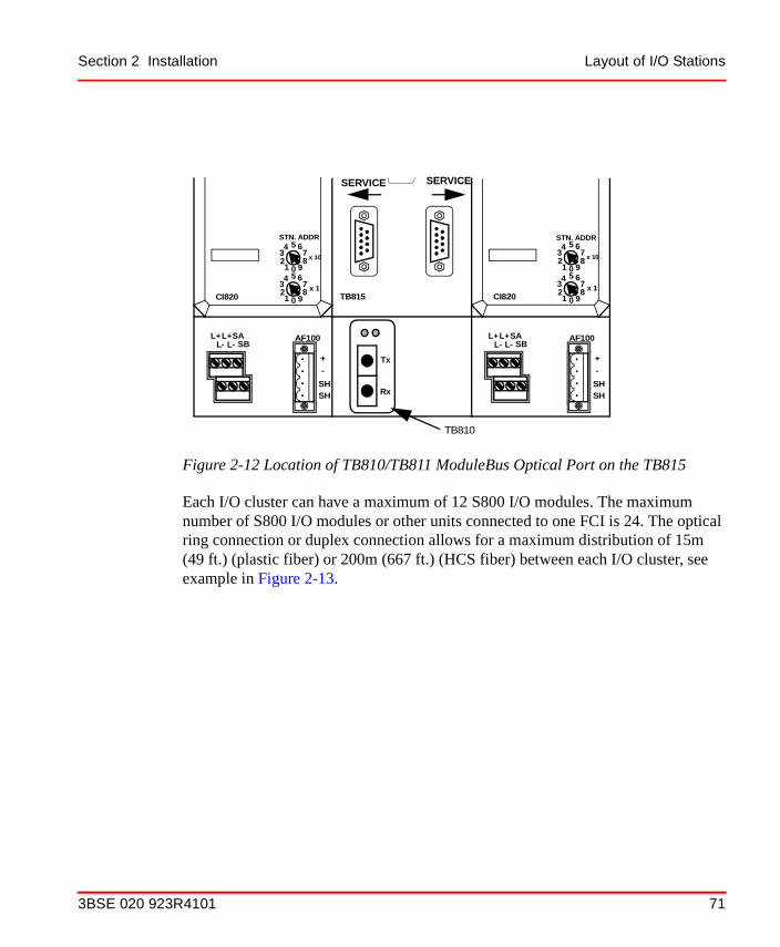
Section 2 Installation Layout of I/O Stations
Each I/O cluster can have a maximum of 12 S800 I/O modules. The maximum number of S800 I/O modules or other units connected to one FCI is 24. The optical ring connection or duplex connection allows for a maximum distribution of 15m (49 ft.) (plastic fiber) or 200m (667 ft.) (HCS fiber) between each I/O cluster, see example in Figure 2-13.
Figure 2-12 Location of TB810/TB811 ModuleBus Optical Port on the TB815
Tx
Rx
SERVICE
SBSA
L-L+L+
L-
STN. ADDR
CI820
012
9
75
38
4 6
012
9
75
38
4 6
x 10
x 1
SBSA
L-L+L+
L-
STN. ADDR
CI820
012
9
75
38
4 6
012
9
75
38
4 6
x 10
x 1TB815
TB810
+-
SHSH
AF100
+-
SHSH
AF100
SERVICE
3BSE 020 923R4101 71

Layout of I/O Stations Section 2 Installation
The TB820 can be used in both a simplex optical configuration as well as in a duplex optical configuration. In a simplex optical configuration, the optical ModuleBus nodes are connected in a ring. In a duplex optical configuration, the optical ModuleBus nodes are connected in a row.
Figure 2-13 Optical ModuleBus Expansion, Simplex and Duplex Configurations
ModuleBus Optical Port TB810
ModuleBus Modem TB820Duplex optical cable (TK811Vxxx)
FCI
15m (49 ft.) Max. (plastic fiber
Fiber Optic Duplex Configuration
Simplex optical cable (TK812Vxxx)
FCI
Fiber Optic Simplex Configuration
15m (49 ft.)Max. (plastic fiber)
TB807 ModuleBus Terminator
72 3BSE 020 923R4101

Section 2 Installation Layout of I/O Stations
The optical ModuleBus Extension fiber optic (plastic fiber) cable comes in three standard lengths:
• TK811V015 (duplex), TK812V015 (simplex) - 1.5 meters (5 ft.)
• TK811V050 (duplex), TK812V050 (simplex) - 5 meters (16 ft.)
• TK811V150 (duplex), TK812V150 (simplex) - 15 meters (49 ft.)
As with the FCI (base cluster), the electrical ModuleBus length must not exceed 2.5 meters from the ModuleBus Modem to the last MTU or S800L module of each cluster. Each cluster requires a TB807 ModuleBus Terminator plugged into the last MTU or S800L module.
Figure 2-14 TB842 and TB806 Connected to CI801 or Redundant CI840 FCIs Through TU847
1
CI801 orTB806
TB842
CI840/TU847
3BSE 020 923R4101 73

Layout of I/O Stations Section 2 Installation
Figure 2-15 TB842 and TB846 Connected to Redundant CI840 FCIs Through TU846
CI840
TU846
TB846
TB842
74 3BSE 020 923R4101

Section 2 Installation Layout of I/O Stations
2.1.4.7 Optical ModuleBus Expansion Redundant Configuration
Redundant Optical ModuleBus Expansion can only be used with redundant AC 800M Controller. Redundant Optical modem TB840/TB840A and TU840 for redundant I/O and TB840 and TU841 for single I/O. See Figure 2-16.
2.1.4.8 I/O Module Installation
Connection of the I/O module to the MTU is made by setting the I/O Module Keys #1 and #2 to the correct setting, place the I/O Module Lock/Switch to the unlock position and then push the I/O module straight onto the MTU. The I/O module is locked and electrically connected to the MTU by the I/O Module Lock/Switch.
Figure 2-16 Optical Module Expansion Redundant Configuration
Figure 2-17 MTU Mechanical Keys for I/O Module and Module Lock
I/O Cluster
TB840/TB840ARedundant AC 800M
ABC
DE F
A
BC
DE F
I/O Module Key #1
A
BC
D
E F
A
BC
D
E F
678910111213141516
RW
12345
24VDI810
I/O Module Lock/Switch(shown unlocked)
I/O Module Lock/Switch(shown locked)
I/O Module Key #2
Turn clockwise to lock I/O Module
3BSE 020 923R4101 75

Layout of I/O Stations Section 2 Installation
Figure 2-18 Mounting of I/O module on MTU
At the mounting of a S800 I/O Box on a Termination Unit the following should be observed:
• Press the Box straight and right on to stop into the Termination Unit. Above shown angle shall be 0°.
• Turn the Locking Device clockwise to its end position. Above shown state with the Locking Device in a position before end position shall not exist for an active module.
Do not turn the I/O Module Lock/Switch counter-clockwise from the unlocked position. This will cause it to break and will make the MTU and the I/O module inoperative.
76 3BSE 020 923R4101

Section 2 Installation Layout of I/O Stations
After all the MTUs or S800L module are connected, the TB807 ModuleBus Terminator connects to the ModuleBus connector of the last MTU or S800L module of the I/O Station. The TB807 has a snap latch (Figure 2-19) that holds it in place. To release the terminator, the latch has to be squeezed to allow removal.
The I/O Station configuration can be as shown in Figure 2-20 and/or as presented in S800 I/O Modules and Termination Units and Example of Enclosure Configurations on page 48.
Figure 2-19 TB807 ModuleBus Terminator Installation
The space between the I/O modules or FCIs are ca 0.8 mm (0.03”)
67
8
FR
W
1
234
5
ModuleBus
Top View
TB807
Terminator
Latch
3BSE 020 923R4101 77

Layout of I/O Stations Section 2 Installation
Figure 2-20 I/O Station Layout with FCI and S800 I/O Modules
Figure 2-21 I/O Station Layout with ModuleBus Modem and S800 I/O Modules
In all installations, two end stops must be mounted on the DIN-rail, one at each end of the station, to prevent the modules from moving along the rail, see Figure 2-20.
826 mm (32.5")
84 58.5 20(0.8)
End Stop
DIN-rail
End Stop
(3.3) (2.3)10
(0.4)mm
(inches)
ModuleBus Modem TB820
58 58.5 20(0.8)(2.2) (2.3)
10(0.4)
443,8 mm (17.5")
Fiber Optic
ModuleBus Cables
mm(inches)
78 3BSE 020 923R4101
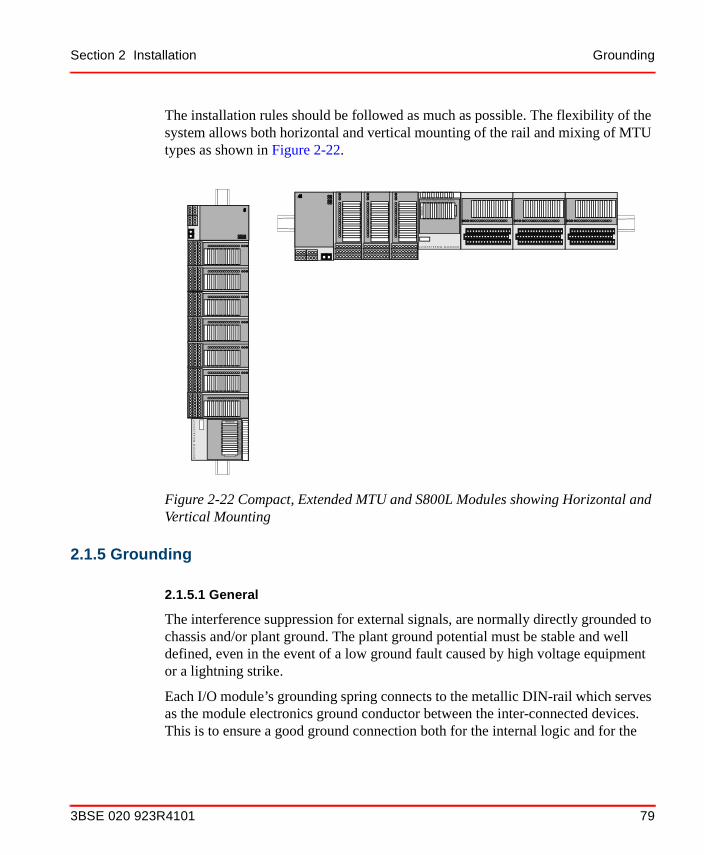
Section 2 Installation Grounding
The installation rules should be followed as much as possible. The flexibility of the system allows both horizontal and vertical mounting of the rail and mixing of MTU types as shown in Figure 2-22.
2.1.5 Grounding
2.1.5.1 General
The interference suppression for external signals, are normally directly grounded to chassis and/or plant ground. The plant ground potential must be stable and well defined, even in the event of a low ground fault caused by high voltage equipment or a lightning strike.
Each I/O module’s grounding spring connects to the metallic DIN-rail which serves as the module electronics ground conductor between the inter-connected devices. This is to ensure a good ground connection both for the internal logic and for the
Figure 2-22 Compact, Extended MTU and S800L Modules showing Horizontal and Vertical Mounting
1 2 3 4 5 6 7 8 9 11 12 13 14 1510 16
Sta
tus
S1 2 3 4 5 6 7 8 9 10 11 12 13 14 15 16
12
34
56
78
911
1213
1415
1016
Status
S1234
5678910111213
141516
3BSE 020 923R4101 79

Grounding Section 2 Installation
EMI immunity and RF emission of the modules. The DIN mounting rail must have a good bond to the PE of the cabinet.
If S800 I/O-modules are configured as two or more groups interconnected with extension cables, special care should be taken to ensure that the DIN-rails of all groups have a good connection to ground. If the DIN-rails are mounted on a common metal sheet, no extra means need be taken except to make sure that each rail has a reliable low ohmic path to the metal plate. Protective earth connection can be made at a single point on the common metal plate.
The ground wire which joins the grounding systems should be ≥35 mm2 (2 AWG) copper (Cu), see Figure 2-23.
2.1.5.2 Protective Earth (PE)
Cabinets supplied with 120/220 V a.c. always must be connected to protective earth (PE) grounding. The equipment PE-conductor should be of 35 mm2 (2 AWG) cross section if copper lead.
2.1.5.3 Grounding of Signals and Voltage Supply
For minimum interference and maximum accuracy, it is normally most effective to ground the signals from transmitters or transducers directly at a grounding point
Figure 2-23 Grounding of Electronic Equipment
M
Shield bar
Ground Plane> 35 mm2
Cabinetsor enclosure
ProtectiveGround
(> 2 AWG)
80 3BSE 020 923R4101

Section 2 Installation Signal Cable Considerations
within the cabinet. It is also advantageous to ground supply voltages for transducers, sensing voltage for contacts, load supply voltage and so on at the same location. All modules have galvanic isolation from the chassis; this means that group-wise isolated modules can be grounded in different equipment as for long as all channels have a common ground reference at the same location.
In the event that the above recommendations (because of measurement techniques or safety regulations) cannot be complied with, be sure to use these methods:
• Signal isolation for analog input signals.
• Digital inputs and outputs are divided into groups at the MTUs and I/O modules, with supply voltage distribution and grounding common for each single groups.
Local grounding of a signal at the transducer location may be a requirement for individual voltage supply to each transducer. This normally hinders the use of MTUs for voltage distribution. A ground bar with the terminal block and fuse equipment required by the application can be used in such cases.
If the transmitter/transducer has galvanic isolation of the supply, its signal zero can be grounded where most suitable for measurement accuracy.
2.1.6 Signal Cable Considerations
When planning for the cable routing in the plant and when selecting suitable cables to be used, the following should be considered:
• Routing of communication cables with regard to a.c. power wiring.
• Mixing of signals and signal types within cables.
• Need of shielded or un-shielded cables.
Cable entry into cabinets is generally from the bottom. Alternative cable entrances can be accommodated if required. Refer to ABB Installation Rules for details.
2.1.6.1 Recommendations for Signal and Process Cable
For use in a typical industrial environment according to the basic protection:
1. Unshielded lines are adequate for binary signals and high level (0...20 mA,±10 V...) analog signals.
3BSE 020 923R4101 81

Signal Cable Considerations Section 2 Installation
2. Shielded cables should be used for low level (RTDs, TC...) analog signals and pulse transducer signals.
3. Minimize the loop area formed between the cable and earth (environment ground), for example by laying the cable on metallic trays that are earthed at several points. Closed cable conduits provide an additional attenuation of up to 30 dB.
4. Usage of binary and analog signals in a multi-core cable works fine, if the following conditions are fulfilled:
– All binary signals are 24 V d.c. or slow varying analog signals.
– Field power supply is earthed to S800 earth.
– All multi-core cable signals are earthed to S800 earth (same earth as the field power supply).
– Binary signals are suppressed. (S800 semiconductor binary outputs have built-in free-wheel diodes for smooth inductive load switching.)
– If cable shield, it should be connected to S800 earth.
– Three wire analog transducers with voltage outputs should have individual power return wires to avoid voltage drop caused by binary loads’ return current.
In other cases use separate cables for analog, binary and heavy current lines. Lay the cables separately sorted according to type.
The signal cables and heavy current cables should be in separate conduits or at least 30 cm apart from each other.
5. The return-conductor should be in the same cable as the signal.
6. The field cables must be wired according to the recommendations ofFigure 2-24.
7. Advant Fieldbus cable installed per the Advant Fieldbus 100 User’s Guide.
8. PROFIBUS-DP cable installed according to PROFIBUS.
For modules with special LED indications see respectively modules in S800 I/O Modules and Termination Units User’s Guide.
82 3BSE 020 923R4101

Section 2 Installation Power Requirements
2.1.7 Power Requirements
2.1.7.1 General
Power supplied to ABB system’s power supply units and for external supply to I/O can normally be obtained from the plant a.c. or d.c. supply sources.
Figure 2-24 Recommended Field Cable Wiring Distances
Power supply cables >600V
Own power supply cablesprocess I/O cables
Cables for communication withmodems = long distance bus(isolated)Video cablesPulse transmission
Cables for communicating withoutmodems = short distance bus(RS232, RS422)
Power supply cables >600 V
Distance 30 cm
Distance 10 cm
Distance 30 cm
I/O device
Field
Zone
Electronic
Zone
PROTECTION
BAR
3BSE 020 923R4101 83

Hazardous Applications Section 2 Installation
2.1.7.2 A.C. Supply
A power source can be rated as Installation Category II or III with respect to level of disturbances, voltage variations and so on, according to IEC standards. Standard voltage range is 110 - 240 V a.c. Installation Category II denotes a higher quality than III mains. The S800 I/O power supplies SD821/SD822/SD823 are rated for Overvoltage Category II for Installation Category III mains.
2.1.7.3 D.C. Supply
2.1.8 Hazardous Applications
I/O modules with Intrinsic Interfaces or standard process I/O modules and MTUs together with isolators or barriers should be used when interfacing towards equipment installed in hazardous locations.
2.1.9 High Voltage Switch-gear Applications
The I/O modules are not designed for direct connection to high voltage switch-gear. Interposing relays are used for digital input and output signals as a connecting link. For analog signals, special transmitters/converters are used.
2.1.10 Lightning Strike Protection
Industrial installations and power plants are normally provided with well-integrated grounding networks installed together with the power distribution system. In installations with such grounding systems, it is not necessary to install lightning strike protection unless overhead wiring or suspended cables are used outdoors.
Table 2-1 Requirements for d.c. Supply Sources
Device Voltage Range
FCI/ModuleBus Modem 19.2 - 30
SD821/SD822 225-250
SD823 250
84 3BSE 020 923R4101

Section 2 Installation Mounting Dimensions
Large plants (water supply installations, refineries and so on) can however have an inadequate grounding system and signal cables can be routed above ground. In such cases lightning strike protection must be used.
Cables outside the grounding system (even for short distances such as 10 m) always require lightning strike protection.
2.1.11 Mounting Dimensions
When placing a control cabinet, specified minimum distances to walls and ceiling must be kept to ensure satisfactory performance.
2.1.11.1 Overhead Clearances
To ensure adequate ventilation, there should be a free space, 150 mm (6") high, between the top of the cabinet and the ceiling, the underside of any beam, duct or similar object over the cabinet. When cables enter the cabinet from above, the space available should be at least 1000 mm (40") high to provide working space, see Figure 2-25.
Figure 2-25 Minimum Distance to Cabinets
Min
150
mm
(6”)
3BSE 020 923R4101 85

Mounting Dimensions Section 2 Installation
2.1.11.2 Rear and Side Clearance
The distance between the rear and the sides of the cabinet and an adjacent wall should be no less than 40 mm (1.6 inches), see Figure 2-26. This will ensure good ventilation.
The free space in front of the cabinet should be the width of the door plus aisle width.
Wall mounted enclosures should use standoffs equal to the clearance requirements.
Figure 2-26 Minimum Distance from Rear and Side of Cabinet to a Wall
Min 40 mm
Min
40
mm
(1.6 inches)
Standoffs for WallMounted Enclosures
(1.6
inch
es)
86 3BSE 020 923R4101

Section 2 Installation Mounting Dimensions
2.1.11.3 Clearances within an Enclosure
Clearances within an enclosure are described in Figure 2-27.
Figure 2-27 Enclosure with 12 Modules and Redundant Station Power Supplies
FC
I
800 mm (31.5")
100
0 m
m (
39.4
")
100 mm (3.9”)
100 mm (3,9”)
100 mm (3,9”)
50 mm (2”) 50 mm (2”)
8 mm (0,03”)8 mm (0,03”)
8 mm
MinMin Min
MinMin
Min
Min
Min
SD SD811 811
8 mm (0,03”)Min
Cable channel
Min 40 mm (1.6”)
Min 25 mm (1”) if the cable channel is higher than 40 mm (1.6”)
I/O
I/O
(0,03”)
3BSE 020 923R4101 87

Installation Procedures Section 2 Installation
2.2 Installation ProceduresAfter some general information in the following section, you will find individual setup descriptions for different parts of the system. The information is given under the following headings if relevant.
• Assembly
• Electric Installation (including Power Supply)
• Functional Measures
• Preparation for Start Up.
Standard installation drawings, terminal diagram forms, and connection documents for site preparation and installation of electrical equipment may apply also.
Equipment Required
The following is a minimum requirement:
• Ordinary hand tools
• Universal instrument, for example, digital multimeter.
• Necessary parts of the documentation listed in Related Documentation on page 19.
• Specific documentation enclosed with the equipment, drawings and so on.
2.2.1 Safety Regulations
The following instructions are to be followed when installing and operating an S800 I/O system to minimize the risks of injury to personnel and damage to the equipment. Local statutory regulations, to the degree that they are more strict than the following are to take precedence.
88 3BSE 020 923R4101

Section 2 Installation Safety Regulations
2.2.1.1 Personnel Safety
The following are to be observed:
• Voltage supply of a cabinet shall never be switched on during installation work.
• All who work on the installation must know the location of the main power supply switch to the equipment and how it is operated.
• When the subsections of the process are checked and a test run has been performed, interlocking links are to be checked by a responsible engineer. All assembly personnel must be informed about test runs to be performed.
• Process technicians are to be present when testing and operating the process device.
2.2.1.2 Equipment Safety
• Avoid direct contact with the bus connector of the I/O modules.
• Always switch off the voltage before extracting a module which can not to be exchanged with power applied, for example, processor units, extension cable adaptors and extension cables, see Section 5, Maintenance. Wait a sufficient time for the capacitors to discharge before removing a power sensitive module.
Work with care when supply voltage is applied to the system. Voltages within the cabinet can cause serious injury or death.
Observe the following safety rules:
3BSE 020 923R4101 89

Grounding in Enclosures Section 2 Installation
2.2.2 Grounding in Enclosures
This section describes where and how grounding is to be done in a cabinet or small enclosures. You should be aware of the common ABB Installation Rules manual which establishes the principals of grounding, knowing when an equipment, a circuit or a cable shield should be grounded. It also gives alternative solutions adapted to specific plant requirements.
2.2.2.1 General
When cabinets are connected together, it forms a stable ground plane for all equipment installed. The signal processing electronics in the modules as well as all interference suppression for external signals is normally directly grounded to chassis and plant ground.
2.2.2.2 Protective Earth
The main power source distribution normally includes a protective ground wire. This shall be connected to the protected earth (PE) terminal block on a primary power switch unit. Use cable lug connectors when connecting on the ground screw.
2.2.2.3 Ground Line
The cabinet is to be grounded with a copper lead (≥35 mm, 2 AWG) to the plant ground line. Cabinets in a row shall be individually connected to the plant ground plane as required.
2.2.2.4 Grounding of Process Cable Shields
Process cable shields are, as applicable, attached directly to the cabinet ground.
2.2.2.5 Grounding of Communication Cable Shields
The shields of communication cables are to be connected directly to the modem or FCI module in an I/O station. This pertains to conventional shielded multi-lead cable. Please refer to the Advant Fieldbus 100 User’s Guide and relevant PROFIBUS documentation for more information.
90 3BSE 020 923R4101

Section 2 Installation Grounding in Enclosures
2.2.2.6 Grounding of Process Signals
There are three applications of signal grounding directly to chassis. (High frequency grounding by capacitors is always provided and not discussed in this context).
• Refer to S800 I/O Modules and Termination Units for the grounding requirements of each I/O module.
• Signals can be commonly grounded by earthing the reference 0 V of centralized power supply for loads and sensing. Such a power supply system must be grounded to the same earth line as the system.
• Individual grounding of a signal in the I/O cabinet is possible (if applicable with respect to I/O module type). The requirement for such an application, is when the signal is not grounded elsewhere, for example, not locally grounded at load/sensor or not grounded via a power supply grounding.
2.2.2.7 Grounding of Additional Equipment
Additional power supply units of different types used by loads or sensor, and modems and so on, and are located in the controller or I/O cabinet, shall be treated in the following way with respect to grounding:
• The apparatus chassis (PE terminal) shall be connected to the installation protective earth terminal or directly to cabinet chassis if the apparatus chassis and bounding are accepted for protective bounding.
• No circuitry of an equipment shall be completely electrically floating but referenced to a suitable potential.
Do not ground the same circuit at different points in the plant.
3BSE 020 923R4101 91

Cable Routing in Enclosures Section 2 Installation
2.2.3 Cable Routing in Enclosures
There are some restrictions in mixing cables within a cabinet due to the risk of interference.To describe the simple rules applicable at site installation, cables are divided in categories. See Table 2-2 and the following rules for custom cabinet installations:
• Within a category cables can be arbitrary mixed.
• The distance between cables belonging to different categories shall be kept > 50 mm (2").
• “Cabinet internal” junctions have their own defined spaces for routing.Distance to other cables should always be > 50 mm (2").
2.2.4 Power Connection
2.2.4.1 General
Cabinets erected side by side including a controller and I/O configuration are regarded as a unit, and are connected to the a.c. (d.c.) power in one single connection point, the centralized Power Switch unit. The switch unit is normally located in the controller cabinet bay.
Table 2-2 Cable Categories in a Cabinet
Cable / Application Category
Power supply (a.c. / d.c.) 1
Process I/O, shielded and unshielded cables 2
Communication 2
ModuleBus extension to S800 I/O 3
92 3BSE 020 923R4101
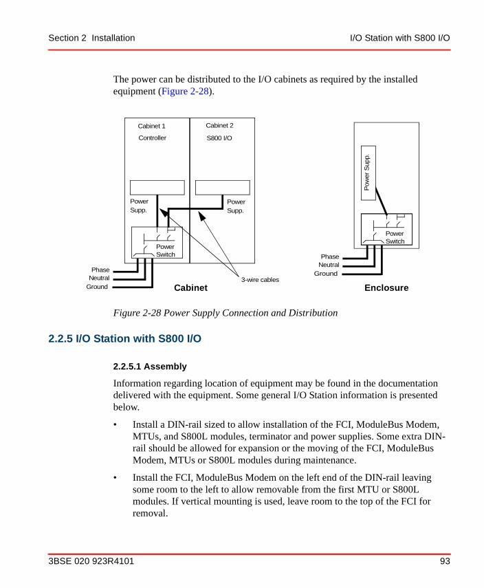
Section 2 Installation I/O Station with S800 I/O
The power can be distributed to the I/O cabinets as required by the installed equipment (Figure 2-28).
2.2.5 I/O Station with S800 I/O
2.2.5.1 Assembly
Information regarding location of equipment may be found in the documentation delivered with the equipment. Some general I/O Station information is presented below.
• Install a DIN-rail sized to allow installation of the FCI, ModuleBus Modem, MTUs, and S800L modules, terminator and power supplies. Some extra DIN-rail should be allowed for expansion or the moving of the FCI, ModuleBus Modem, MTUs or S800L modules during maintenance.
• Install the FCI, ModuleBus Modem on the left end of the DIN-rail leaving some room to the left to allow removable from the first MTU or S800L modules. If vertical mounting is used, leave room to the top of the FCI for removal.
Figure 2-28 Power Supply Connection and Distribution
Cabinet 1 Cabinet 2
Controller
PowerSwitch
Phase
Ground3-wire cablesNeutral
Cabinet Enclosure
PowerSwitch
Phase
GroundNeutral
Pow
er S
upp.
S800 I/O
PowerSupp.
PowerSupp.
3BSE 020 923R4101 93

I/O Station with S800 I/O Section 2 Installation
• Install the first MTU or S800L modules to the right (below) of the FCI or ModuleBus Modem and all other MTUs or S800L modules to the right (below) of the preceding MTU or S800L module.
• The last MTU or S800L module (12 max.) connected to the FCI or ModuleBus Modem will have the TB807 Terminator installed in the ModuleBus connector.
• Set each MTU mechanical keys to the correct setting for the I/O module that will be located there.
• The power supply modules may be located on the same DIN-rail as the FCI or ModuleBus Modem and the I/O modules, but should be always located on a horizontal DIN-rail because of its weight.
• Install an end stop before the first module and after the last one on the DIN-rail.
• Then proceed with the electrical connections as necessary.
2.2.5.2 Electric Installation
Advant Fieldbus 100 Fieldbus Connection
The AF100 Fieldbus is connected to the terminals of a CI810 or a CI820. The incoming fieldbus twisted pair cable is connected to a plug connector with four terminals, two for the signal wires and two for the shield. The incoming and out going fieldbus signal + conductors are terminated in the + terminal. The - conductors are both terminated in the - terminal. The cable shield drain wires are terminated in the two SH terminals and they must be bridged to ensure a continuous shield connection in case the fieldbus plug is removed from the FCI. Keep the drain wires as short as possible (< 50mm). If the unit is at the end of the bus, a terminator (TK501Vxxx) must be connected. Please refer to the Advant Fieldbus 100 User’s Guide for complete details.
PROFIBUS Fieldbus Connection
The PROFIBUS fieldbus is connected to the terminals of a CI830/CI840. The incoming fieldbus cable is connected to a 9 pin D-way connector. If the unit is at the end of the bus, a connector with termination must be used. Please refer to relevant PROFIBUS documentation.
94 3BSE 020 923R4101
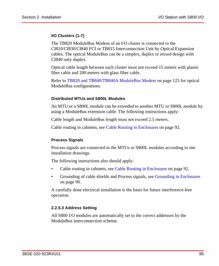
Section 2 Installation I/O Station with S800 I/O
I/O Clusters (1-7)
The TB820 ModuleBus Modem of an I/O cluster is connected to the CI810/CI830/CI840 FCI or TB815 Interconnection Unit by Optical Expansion cables. The optical ModuleBus can be a simplex, duplex or mixed design with CI840 only duplex.
Optical cable length between each cluster must not exceed 15 meters with plastic fiber cable and 200 meters with glass fiber cable.
Refer to TB820 and TB840/TB840A ModuleBus Modem on page 125 for optical ModuleBus configurations.
Distributed MTUs and S800L Modules
An MTU or a S800L module can be extended to another MTU or S800L module by using a ModuleBus extension cable. The following instructions apply:
Cable length and ModuleBus length must not exceed 2.5 meters.
Cable routing in cabinets, see Cable Routing in Enclosures on page 92.
Process Signals
Process signals are connected to the MTUs or S800L modules according to site installation drawings.
The following instructions also should apply:
• Cable routing in cabinets, see Cable Routing in Enclosures on page 92.
• Grounding of cable shields and Process signals, see Grounding in Enclosures on page 90.
A carefully done electrical installation is the basis for future interference-free operation.
2.2.5.3 Address Setting
All S800 I/O modules are automatically set to the correct addresses by the ModuleBus interconnection scheme.
3BSE 020 923R4101 95

I/O Station with S800 I/O Section 2 Installation
The FCI module station address should be set to the assigned PROFIBUS address or Advant Fieldbus 100 station set by the station address switches. Refer to S800 I/O Fieldbus Communication Interface for PROFIBUS-DP/DPV1 or S800 I/O Fieldbus Communication Interface for Advant Fieldbus 100 manual as to location of address switches.
The ModuleBus Modem cluster address should be set to the assigned cluster number by the cluster address switch. Refer to TB820 ModuleBus Modem on page 38.
2.2.5.4 Check of the External Wiring
The level of workmanship must be judged case by case, and the results will determine the need for a check of all connections before the system is powered up. It is possible to check, with a buzzer, that the external wiring to the process equipment is correct and that all conductors are intact. The check of the field wiring should be done before the I/O modules are installed. It is also possible, without activating the control equipment, to check that transmitters, transducers and actuators (including all process wiring) to see if they function correctly. This makes it necessary to connect voltage to these units and develop suitable checking methods.
An alternative method, is to make an integrated check of the process equipment, wiring and the corresponding controller functions. This should be done on a point by point basis. Preferably the controller should be loaded with the application data base. The data base is then used as one check-point. Status / values can be read and control signals to process devices can be simulated by an operator station.
Be aware of the risk of “accidents”. Short-circuit and over-voltage can damage the equipment, for example, a process I/O board or field element.
96 3BSE 020 923R4101

Section 2 Installation Checklists
2.2.6 Checklists
The following checklists, Table 2-3 to Table 2-10, are a summary of important information that should be checked for the installation.
2.2.6.1 Grounding Philosophy, Ground Plane System
Table 2-3 Grounding Philosophy, Grounding System
Item Concerning Check
Grounding philosophy
Ground system Grounding to PE network only. Only one ground system. No exceptions.
Ground plane system
Design The ground line system of the installation must be carefully installed and must incorporate the switchgear.
3BSE 020 923R4101 97

Checklists Section 2 Installation
2.2.6.2 Process Cabling, Shielding, Grounding, Max. Length
Table 2-4 Process Cabling, Shielding, Grounding, Max. Length
Item Concerning Check
Cables Prescribed type Communication cables
Pulse transducer cables
Shielded for low level AI (RTD, Pt, thermocouple, and so on).
Signal wire and return wire in same cable
Shielding: Single shield
Grounding:AI, AO, DI, DO,
Should be grounded directly as it comes into the cabinet
Grounding:Communications
For AF 100, see the Advant Fieldbus 100 User’s Guide. For PROFIBUS see relevant documentation.
Multi-core signal cable
Grounding All signals in a multi-core cable shall refer to a common ground
A.C. digital inputs 120 V and 230 V
Max. cable length Approximately 200 m (656 ft.)
98 3BSE 020 923R4101

Section 2 Installation Checklists
2.2.6.3 Power Supply
Table 2-5 Supply
Item Concerning Check
A.C. Power Mains
Connection in cabinet
PhaseReturnProtective ground (if distributed)
Note: There must be no breaks in the protective ground conductor to the PE terminal.
No unsuppressed load
No unsuppressed load on same finale circuit from distribution box
Use of interference-sensitive power supply units
Special isolation transformer for electronics supply must be used
Internal distribution Incoming power supply (120, 230 V) must be separated from other cables by 50 mm (2") or more
D.C. (floating supply)
Grounding, supply Floaty supply is permitted if supply voltage to S800 ground is not >50 V. If >50V, use an isolating d.c./d.c. converter.
D.C. (grounded supply)
Connection S800 can be direct connected if supply voltage to S800 ground is not >50 V. If >50V, use an isolating d.c./d.c. converter.
I/O Station Supply
Max. power output < 90% of regulator capacity
3BSE 020 923R4101 99

Checklists Section 2 Installation
2.2.6.4 Lightning Protection
2.2.6.5 MTU, I/O Module
Table 2-6 Lightning Protection
Item Concerning Check
Lightning protection
Protections are compulsory for all circuits in:
Overhead lines
Cables that leave the general ground line network
Table 2-7 MTU, I/O Module
Item Concerning Check
Mounting rail
(for MTUs)
Ground connection to cabinet chassis via DIN rail mounting screws
If problems, check R < 100 mΩ, measured with equipment switched off and cables disconnected
MTU Ground connection DIN rail mounting screws (100 mm pitch) fully tightened
100 3BSE 020 923R4101

Section 2 Installation Checklists
2.2.6.6 Cabinet, Internal Cables
Table 2-8 Cabinets, Internal Cables
Item Concerning Check
Row of cabinets Electrical connection (grounding)
Through 35 mm2 (2 AWG) copper conductors joining the PE terminals in each cabinet.
Cabinet parts (plates)
All parts electrically connected to each other and to the PE bar
R < 100 mΩ
Grounding in cabinet
Design Only one grounding system. NO EXCEPTIONS
Temperature in cabinet
Max. permitted temperature for continued operation
Max. permitted temperature for continued operation in cabinet is 0 to +55°C (32 to 131°F)(1).Measured just below the I/O module. Modules on compact MTUs or S800L modules on a vertical DIN rail allow 0 to +40°C (32 to 104°F)(1) ambient temperature. See Table 3-7.
(1) Non-condensing
Radio emission Emission S800 equipment does not require radio proof enclosures.
Shielded cable Design Communication, pulse transducers and analog circuits for Low Level (RTD Pt, thermocouples) must be shielded. Please refer to module documentation for details.
Internal cables Routing See Cable Routing in Enclosures on page 92.
Check that there is no tension in the wiring.
3BSE 020 923R4101 101
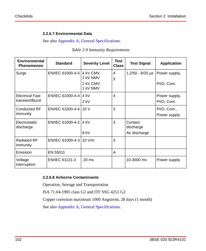
Checklists Section 2 Installation
2.2.6.7 Environmental Data
See also Appendix A, General Specifications.
2.2.6.8 Airborne Contaminants
Operation, Storage and Transportation
ISA 71.04-1985 class G2 and ITF SSG 4251 G2
Copper corrosion maximum 1000 Angstrom, 28 days (1 month)
See also Appendix A, General Specifications.
Table 2-9 Immunity Requirements
Environmental Phenomenon
Standard Severity LevelTest
ClassTest Signal Application
Surge EN/IEC 61000-4-5 4 kV CMV,2 kV NMV
2 kV CMV, 1 kV NMV
4
3
1,2/50 - 8/20 µs Power supply,
PI/O, Com.
Electrical Fast transient/Burst
EN/IEC 61000-4-4 4 kV
2 kV
4 Power supply,
PI/O, Com.
Conducted RF immunity
EN/IEC 61000-4-6 10 V 3 PI/O, Com.,
Power supply
Electrostatic discharge
EN/IEC 61000-4-2 4 kV
8 kV
3 Contact discharge
Air discharge
Radiated RF immunity
EN/IEC 61000-4-3 10 V/m 3
Emission EN 55011 A
Voltage interruption
EN/IEC 61131-2 20 ms 10-3000 ms Power supply
102 3BSE 020 923R4101

Section 2 Installation Final Procedure Before Start-up
2.2.6.9 Miscellaneous
2.2.6.10 External Cables
When selecting cables that are to be used in the plant environment, you should know that there are some restrictions and rules to follow:
• Routing of communication cables.
• Mixing of signals and signal types within cables.
• Need of shielded cables.
2.2.7 Final Procedure Before Start-up
Remove all debris from the work performed and clean off all grease and dirt. Check that no tools or assembly material are left in the cabinets. Vacuum clean the cabinets.
Table 2-10 Miscellaneous
Item Concerning Action
Non suppressed inductive loads
Cable routing Cabling to non-suppressed inductive loads in cabinets must be kept more than 100 mm (4") away from internal cables
Non suppressed inductive loads
Power supply Use separate power supply
Thermocouples Position of AI835 “CJC” RTD Cold Junction Compensation)
CJC RTD should be placed where the TC’s compensation cable is terminated
Analog inputs External grounded transmitters
Use analog input modules with differential channels or isolated external amplifier.
Analog inputs / outputs
External grounded receivers
Use analog output modules with isolated channels.
3BSE 020 923R4101 103
Start-up and Shut-down Procedures Section 2 Installation
2.3 Start-up and Shut-down Procedures
2.3.1 Start-up Procedures
This section includes power up for the very first definition/configuration of the system resources. A visible result of the start-up procedures, are that all red LED on module fronts are turned off and all green LED are turned on.
2.3.1.1 Safety Regulations
The instructions given in Safety Regulations on page 88 are applicable in all situations when working with S800 I/O and associated equipment. Please read the instructions carefully.
2.3.1.2 Controller and I/O
When the set-up activities are finished and after using Checklists on page 97, the equipment will be ready for start-up, but first read the following security guidelines before proceeding.
2.3.1.3 Security Guidelines
During the power up of S800 I/O there is always a risk of spurious output signals to the process due to a faulty hardware module.
Critical process devices should always be identified and isolated in some way if the process is energized. Examples of different methods are:
• Disconnected output power supply.
• Disconnect the process cables from outputs.
• Remove output S800 I/O modules.
Succeeding operations after power up, including necessary tests, must be performed carefully.
Work with care when supply voltage is applied in the system. The voltage in the cabinet can cause serious injury or death.
104 3BSE 020 923R4101

Section 2 Installation Shut-down Procedures
2.3.2 Shut-down Procedures
Before power is switched on, and start-up of the equipment, it is important to know how to shut-down in different situations. This is described below.
2.3.2.1 Safety Regulations
The instructions given in Safety Regulations on page 88 are applicable in all situations when working with a Controller and associated equipment. Please read the instructions carefully.
2.3.2.2 Emergency Shut Down
An emergency stop should always be available. It shall be controlled by local regulations. This is a responsibility of the plant design and construction. The controller system does not supply this special function.
Check the Location of the Emergency Stop and use it in an Emergency Situation
From the electrical and functional point of view, an emergency stop will have the same consequences to the controller and associated equipment as a safety shut down.
2.3.2.3 Safety Shut Down
The Advant Controller and its S800 I/O may be mounted in a row of joined cabinets and are connected as a single unit to the mains power source. The I/O Station with S800 I/O may also be located remotely in the process area and have its own power source. Safety shut down, by disconnecting the controller or remote enclosure from the mains, can be carried out in two ways:
• As prescribed in the site planning Power Requirements on page 83, there should be a common safety switch installed within 3 m (10 feet) of the cabinets.
• Check the Location of the Safety Switch and use it when working with the Equipment
Work with care when supply voltage is applied in the system. The voltage in the cabinet can cause serious injury or death.
3BSE 020 923R4101 105

Shut-down Procedures Section 2 Installation
The safety switch should be arranged to shut down the power of not only the electronics system but also transmitters, transducers and other process devices. In other words, a total power shut down for the plant section controlled.
Regardless of the way, the results and consequences of a shut down will be:
– Zero output to the process devices (S800 I/O).
– De-energized output relays (S800 I/O). Not for normally closed contacts.
– The system is ready for a restart. Restart can be performed when the reason for the shut down is cleared away.
2.3.2.4 Manual Stop
Beyond the most drastic way of shut down, by disconnecting power, there is an other way to “stop” the S800 I/O:
• Stop program execution in the controller
• Disconnect the I/O station from the fieldbus.
The results of the manual stop method:
• Output modules goes to the OSP state.
• The system is ready for a restart. Restart can be performed by starting the execution in the controller or connecting the fieldbus.
After necessary measures, a restart can take place.
Since the safety switch is a plant component this document can not stipulate and describe the design exactly. Please check the plant documentation in this respect carefully. Instructions, as to the extent of the power shut down, should preferably be attached to the safety switch.
106 3BSE 020 923R4101

Section 2 Installation Product Verification
2.4 Product VerificationAs the test requirements vary considerably between different installations, the system engineer is responsible for determining the functional requirements which apply.
Equipment Required
The following equipment is a minimum requirement:
• Necessary parts of the documentation listed in Related Documentation on page 19.
• Specific documentation enclosed with the equipment.
In more complex installations which include closed loop control some additional test equipment can be necessary/practical at tuning:
• Access to an operator station for loop tuning.
2.4.1 General
A general description of how to set the controller in operation and start the execution of application program is presented in the Advant Controller manuals. Once the system is started and ready for operation the I/O can be checked.
General information for some functional tests, which can be made to verify the S800 I/O are presented in the following sections.
2.4.1.1 Check of Process Input/Output Systems
With the application program running in the controller, the inputs and outputs can be checked. This should be done by using a signal by signal procedure. The data base is then used as a final check-point.
3BSE 020 923R4101 107

General Section 2 Installation
It may be necessary to simulate digital and analog input signals which are normally generated by the process. Suitable methods are:
• Digital inputs: Activate the input by connecting a voltage which corresponds to the nominal value of the input. The “1” and “0” status is simulated by opening and closing the terminal connections. Activate the input as close to the process transducer as possible to test the process wiring as far as possible. Manual operation of transducers, for example, limit switches can also give the required change for the input signals.
• Analog input signals: Use a signal generator for analog signals. A simple test coupling can be used as a voltage source. This can consist of a potentiometer across a suitable voltage source which gives +/- voltage. A current source, which can give sufficient current, for example, 20 mA, is required for current signals. Analog input test signals should be entered as close to the transmitter/transducer as possible to test the process wiring.
Digital and analog output signals are obtained by setting the required values from the overlaying controller.
2.4.1.2 Input Signals
Figure 2-29 shows where an input signal can be checked in an S800 I/O application.
108 3BSE 020 923R4101

Section 2 Installation General
DI modules provide a field input connector and DI channel LED’s, and AI modules provide a field input connector.
Figure 2-29 Block Diagram of S800 I/O Input Channel, Test Points
Controller
InputModule
DI ch.
Engineering Tool
Application
FCI Fieldbus Interface
Process
ProcessDevice
3BSE 020 923R4101 109

General Section 2 Installation
• Digital Input Signals
A digital input signal can be checked as shown in Figure 2-29. Use the following procedure as a guide:
– Simulate the digital input signal as close to the process transducer as possible or activate the transducer itself.
– Check that the corresponding yellow LED on the input module concerned illuminates and that the change is shown accordingly in the overlaying controller
– Change the input signal to a low level. Check that the yellow LED on the input board extinguishes and that the display value has changed.
• Analog Input Signals
Figure 2-29 shows where an analog input signal of an input channel can be checked. Proceed as follows to check an analog input channel:
– Simulate the analog input signal as close to the process transmitter/transducer as possible.
– Check that the simulated signal is available at the screw terminal of the corresponding connection.
– Check that the value shown on the display screen corresponds to the simulated value set in the field. Check the complete signal range.
2.4.1.3 Output Signals
Figure 2-30 shows where an output signal can be checked in an S800 I/O application.
DO Modules provide a field output connector and DO channel LED’s.
AO Modules provide a field output connector.
110 3BSE 020 923R4101

Section 2 Installation General
• Digital Output Signals
Typical digital output channels and where the signals can be tested are shown in Figure 2-30. Digital output signals in a specific plant are shown in the terminal diagrams for the plant.
Proceed as follows to check digital channels:
– Check that the corresponding output shows that it is set to on.
– Check that the corresponding yellow LED on the digital output module illuminates.
– Check the value on the screw terminal block, and if practical also at the process device.
• Analog Output Signals
When checking analog output signals, use a multimeter to test for an output signal over the complete signal range.
Figure 2-30 Block Diagram of S800 I/O Output Channel, Test Points
ProcessController
OutputModule
DO ch.
Application
FCI Fieldbus Interface
Engineering Tool
ProcessDevice
3BSE 020 923R4101 111

Final Check Section 2 Installation
Typical analog output channels and where the signals can be tested are shown in Figure 2-30. Analog output signals in a specific plant are shown in the connection diagrams for the plant.
Proceed as follows to check analog channels:
– Set the output value, and check that the corresponding output shows this value.
– Measure the value on the screw terminal block, and if practical also at the process.
– When checking analog output signals use a multimeter to test that an output signal is obtained over the complete signal range.
2.4.2 Final Check
When the test of the control system is complete, and the plant functions satisfactorily, the following actions should be taken:
• Check that all S800 I/O modules are properly inserted in the MTUs.
• Check that all terminal screws on MTUs and S800L modules are properly tightened and that all grounds are good.
• Check that all cable connectors are properly mated.
• Check that all cable coverings or tie wraps are installed properly to avoid cable wear.
• Check that no tools or debris from installation remain in the cubicle. Clean the cabinet.
112 3BSE 020 923R4101
Section 3 Configuration
3.1 Design ConsiderationsThis section provides guidelines and other information that you need to know before designing and configuring the S800 I/O. This information includes an overview of the hardware and database configuration guidelines.
3.1.1 I/O Station Layout Hardware Configuration Guidelines
The S800 I/O is DIN rail mounted. The rail can be any practical length to fit the needs of that particular I/O Station. A S800 I/O cluster can have a maximum length of the ModuleBus from the ModuleBus master, TB815 Interconnection Unit, or ModuleBus Modem to the ModuleBus terminator of 2,5 meters (8.2 feet). See Figure 3-1 for maximum layout of station using Compact MTUs.
3BSE 020 923R4101 113
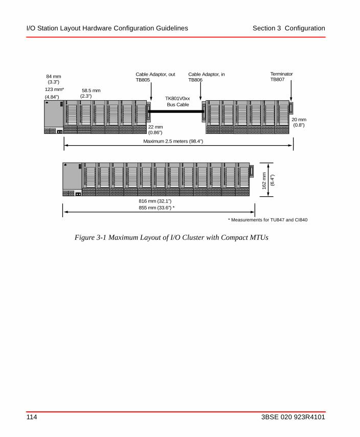
I/O Station Layout Hardware Configuration Guidelines Section 3 Configuration
Figure 3-1 Maximum Layout of I/O Cluster with Compact MTUs
Maximum 2.5 meters (98.4”)
Cable Adaptor, outTB805
Cable Adaptor, inTB806
TerminatorTB807
Bus Cable
84 mm
58.5 mm
22 mm
816 mm (32.1”)
162
mm
20 mm
TK801V0xx
(0.8”)
(0.86”)
(3.3”)
(2.3”)
(6.4
”)
123 mm*
(4.84”)
* Measurements for TU847 and CI840
855 mm (33.6”) *
114 3BSE 020 923R4101

Section 3 Configuration I/O Station Layout Hardware Configuration Guidelines
See Figure 3-2 for maximum layout of I/O cluster using Extended MTUs.
Figure 3-2 Maximum Layout of I/O Cluster with Extended MTUs
1554 mm
20
(61,2”)
84 120 22 mm
469 mm (18.5”)
1129 mm
Bus CableLength = 300 mm
162
mm
109 mm
120(4.74”)
(0.8”)
(0.86”)
(4.3”)
(44.5”)
(6.3
7”)
(11.8”)
mm(inches)
84 (3.3”)
123 (8.44)*123*
* Measurements for TU847 and CI840
1593 mm(62.7”)*
508 mm (20”) *
3BSE 020 923R4101 115
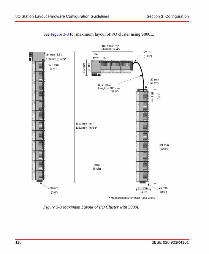
I/O Station Layout Hardware Configuration Guidelines Section 3 Configuration
See Figure 3-3 for maximum layout of I/O cluster using S800L.
Figure 3-3 Maximum Layout of I/O Cluster with S800L
1143 mm (45”)
20 mm
1182 mm (46.5”)*
8485.8
22 mm
406 mm (16”)*
821 mm
Bus CableLength = 300 mm
162
mm
110 mm
85.8 mm(3.4”)
(0.8”)
(0.87”)
(4.3”)
(32.3“)
(6.3
8”)
(11.8”) 85.8 mm
123
456
789
1112131415
1016
Status S12345678910111213141516
1234
5678
911
1213141510
16
Status S12345678910111213141516
1234
567
8911
1213141510
16
Status S12345678910111213141516
123
4567
89
1112131415
1016
Status S12345678910111213141516
123
456
789
1112131415
1016
Status S12345678910111213141516
12
3456
789
1112131415
1016
Status S12345678910111213141516
1234
567
8911
1213141510
16
Status S12345678910111213141516
123
4567
89
1112131415
1016
Status S12345678910111213141516
123
456
789
1112131415
1016
Status S12345678910111213141516
1 2 3 4 5 6 7 8 9 11 121314 1510 16
Sta
tus
S12345678910111213141516
1 2 3 4 5 6 7 8 9 11 12 13141510 16
Sta
tus
S12345678910111213141516
1 2 3 4 5 6 7 8 9 11 12 13 141510 16
Sta
tus
S12345678910111213141516
1234
567
8911
1213141510
16
Status S12345678910111213141516
1234
5678
911
1213141510
16
Status S12345678910111213141516
123
456
789
1112131415
1016
Status S12345678910111213141516
123
4567
8911
1213141510
16
Status S12345678910111213141516
123
456
789
1112131415
1016
Status S12345678910111213141516
1234
5678
911
1213141510
16
Status S12345678910111213141516
123
4567
8911
1213141510
16
Status S12345678910111213141516
1234
567
8911
1213141510
16
Status S12345678910111213141516
1234
5678
911
1213141510
16
Status S12345678910111213141516
123
4567
8911
1213141510
16
Status S12345678910111213141516
123
4567
89
1112131415
1016
Status S12345678910111213141516
1234
5678
911
1213141510
16
Status S12345678910111213141516
20 mm
(0.8”)
22 mm(0.87”)
(3.4”)
mm(inch)
84 mm (3.3”)
123 mm (8.43”)* 123*
* Measurements for TU847 and CI840
367mm (14.4”)
116 3BSE 020 923R4101

Section 3 Configuration I/O Station Layout Hardware Configuration Guidelines
An I/O cluster may be divided into smaller parts to fit a particular requirement, but the 2.5 meter (8.2 feet) maximum must be observed at all times. The cluster may be distributed because of space limitations or to keep signal types together. See Figure 3-4 for a example of an I/O cluster divided up into four groups.
The first unit of the I/O Station is the Fieldbus Communications Interface (FCI). It connects to the fieldbus and is the communications interface to the I/O modules. The FCI controls the ModuleBus and provides power to the logic-side of the I/O modules. The FCI is a station on the fieldbus and must be set to the correct address. Refer to respective FCI manual for more information.
The FCI connects to the first MTU or S800L module. Additional MTUs or S800L modules connect to each other or through the ModuleBus Extension cable, up to a maximum of 12. The ModuleBus is terminated by the TB807 Bus Terminator module. The I/O Modules are installed onto the MTUs and connected to the process in the field.
Figure 3-4 I/O Cluster in Small Groups
Cable Adaptor, out
TB805
Cable Adaptor, in
TB806
Terminator
TB807
Dig
ital I
nput
s
Ana
log
Inpu
ts
Analog Outputs Digital Outputs
TK801V0xx
1 2 3 4 5 6 7 8 9 11 12 13 14 1510 16
Sta
tus
S12345678910111213141516
3BSE 020 923R4101 117

Redundant FCIs for Advant Fieldbus 100 Section 3 Configuration
3.1.2 Redundant FCIs for Advant Fieldbus 100
An I/O Station with redundant CI820 FCIs requires that the ModuleBus Extension cable be connected to the TB815 Interconnection Unit and then to the first I/O Module. The maximum ModuleBus length from the TB815 to the ModuleBus terminator is 2.5 meters. See Figure 3-5 for layout of a station.
3.1.3 Redundant FCIs and I/O Modules for PROFIBUS
An I/O Station with redundant CI840 FCIs can have the first I/O module connected direct to the MTU TU846. ModuleBus Extension cables can be connected via a ModuleBus Cable Adaptor-Out TB845 and a ModuleBus Cable Adaptor-In TB846.
Figure 3-5 I/O Station with Redundant CI820 FCIs
Cable adaptor, in
TB806
TerminatorTB807
TK801V0xx
CI820 FCI
TB815InterconnectionUnit
Cable adaptor, out
TB805
118 3BSE 020 923R4101

Section 3 Configuration Redundant FCIs and I/O Modules for PROFIBUS
The maximum ModuleBus length from the TU846 to the ModuleBus terminator is 2.5 meters. See Figure 3-6 for layout of a station.
Figure 3-6 I/O Station with Redundant CI840 FCIs and Redundant I/O Modules
CI840 FCI
TerminatorTB807
Cable adaptor, in
TB846
Cable adaptor, out
TB845
MTU
TU846
3BSE 020 923R4101 119

I/O Clusters Section 3 Configuration
3.1.4 I/O Clusters
I/O clusters 1-7 connect to the Optical ModuleBus port on the FCI or TB815 Interconnection Unit by Optical Expansion cables. Each I/O station can have up to 24 I/O modules and each I/O cluster can have up to 12 I/O modules. The 24 V power supply has to be connected to each cluster. See Figure 3-7 to Figure 3-11 for an example of optical ModuleBus Expansion cabling.
Figure 3-7 Optical ModuleBus Extension non-redundant, CI801
ModuleBus Modem TB820
CI801 Base I/O Cluster
I/O Cluster 1
I/O Cluster 2
I/O Cluster 3
Sta
tus
120 3BSE 020 923R4101

Section 3 Configuration I/O Clusters
Figure 3-8 Optical ModuleBus Extension non-redundant, CI810, CI820, CI830
ModuleBus Modem TB820
CI810/CI830 FCI
Base I/O Cluster
I/O Cluster 1
I/O Cluster 2
I/O Cluster 3
Optical ModuleBus Port TB810
ModuleBus Modem TB820
Base I/O Cluster
I/O Cluster 1
I/O Cluster 2
I/O Cluster 3
Optical ModuleBus Port TB810
CI820 FCI
TB815InterconnectionUnit
3BSE 020 923R4101 121

I/O Clusters Section 3 Configuration
Figure 3-9 Optical ModuleBus Extension non-redundant, CI840 with single I/O
ModuleBus Modem TB820
CI840 Base I/O Cluster
I/O Cluster 1
I/O Cluster 2
I/O Cluster 3
122 3BSE 020 923R4101

Section 3 Configuration I/O Clusters
Figure 3-10 Optical ModuleBus Extension non-redundant, CI840 with redundant I/O
ModuleBus Modem TB820
CI840 Redundant I/O
I/O Cluster 1
I/O Cluster 2
I/O Cluster 3
TB846
TB842
3BSE 020 923R4101 123

CI801/CI810/CI820/CI830/CI840 FCI Section 3 Configuration
3.1.5 CI801/CI810/CI820/CI830/CI840 FCI
The FCI needs to be connected to a fieldbus and have an address selected. It is also connected to a 24 V d.c. power source to provide power to the I/O Station. Also refer to appropriate FCI manual for information on how to estimate the fieldbus and power loading of each I/O station configuration.
Figure 3-11 Redundant Optical ModuleBus Extension with Redundant TB840/TB840A
I/O Cluster (single I/O)
TB840/TB840ARedundant AC 800M
I/O Cluster (redundant I/O)
124 3BSE 020 923R4101

Section 3 Configuration TB820 and TB840/TB840A ModuleBus Modem
3.1.6 TB820 and TB840/TB840A ModuleBus Modem
The TB820 ModuleBus Modem needs to be connected to the Optical ModuleBus, and have an I/O cluster address selected. It is also connected to a 24 V d.c. power source to provide power to the I/O modules of the cluster.
The TB840/TB840A ModuleBus Modem must be mounted on a TU841 Module Termination Unit and needs to be connected to the Optical ModuleBus, and have an I/O cluster address selected. It is also connected to a 24 V d.c. power source to provide power to the I/O modules of the cluster.
Figure 3-12 Front Panel of the TB820 ModuleBus Modem
12
75
34 6 Cluster Address
Switch (Address 4 shown)
CLUSTER
F R
ORx2ORx1
P
TB820 V2
ERx
Optical ModuleBusInterface Connector (X4, X5)
X4 X5Rx TxRx Tx
SBSA
L+L-
3BSE 020 923R4101 125

TB820 and TB840/TB840A ModuleBus Modem Section 3 Configuration
3.1.6.1 Cluster Address Switch
The TB820 is equipped with a rotary switch used as the I/O cluster address selector for the I/O cluster. The address switch for TB840/TB840A is placed on TU841. The I/O cluster address is in the range of 1 to 7. The FCI is base cluster address 0 (zero).
Figure 3-13 TB840/TB840A ModuleBus Modem mounted on TU841
CLUSTER ADDR.
126 3BSE 020 923R4101
Section 3 Configuration TB820 and TB840/TB840A ModuleBus Modem
Figure 3-12 shows the front panel of the TB820 and Figure 3-13 the front panel of the TB840/TB840A.
3.1.6.2 Optical ModuleBus Connections
The TB820/TB840/TB840A has a connection to the optical ModuleBus by the optical ports on its side. The fiber optic cable(s) connect to the X4 (Tx and Rx ports) and X5 (Tx and Rx ports) connectors of the TB820/TB840/TB840A.
The optical ModuleBuses can be connected to duplex or simplex fiber optic cables. See Figure 3-14 for connection details.
Care must be taken that no I/O clusters have the same address setting. This could result in output modules in the same ModuleBus position but in different I/O clusters putting out the same value.
On TB820, a new cluster address should not be set during operation. If the address changes are done during operation, the cluster is disconnected from the ModuleBus, and no communications is possible with the I/O modules on that cluster address.
The new address is set at reset or power up. If the address changes are done on TB840 during operation, the cluster will get a warning signal and the new address will not be set until reset or power up.
TB820 can not handle High Integrity I/O modules (AI880, DI880 and DO880).
3BSE 020 923R4101 127

TB820 and TB840/TB840A ModuleBus Modem Section 3 Configuration
The connector style, either simplex or duplex, all provide snap-in action when mated to the X4/X5 ports. Simplex connectors are color coded to facilitate identification of transmitter (Tx) or receiver (Rx) connections. Duplex connectors are keyed so that proper orientation is ensured during insertion.
Figure 3-15 shows a duplex, simplex and mixed configuration of the optical ModuleBus. Duplex (two-way) is normally the best communication design, but may not apply to all requirements. Duplex design allows additional TB820s or TB840/TB840As to be added down-stream on-line.
Simplex (one-way) connections provide a ring configuration from the FCI to the first TB820/TB840/TB840A, then to the next and so on and then back to the FCI. Simplex designs will require that the “home-run” cable from the last TB820/TB840/TB840A back to the FCI, or another TB820/TB840/TB840A, is limited to the 15 meter (49 ft.) plastic fiber or 200 meter (667 ft.) HCS fiber cable length. The 15 meter (49 ft.) cable length or 200 meter (667 ft.) maximum applies
Figure 3-14 TB820 and TB840 Optical ModuleBus Connections
Interface ConnectorsSBSA
L-L+ L+
L-
TB820
Rx
Tx
Duplex Fiber Optic Cable Connector
Simplex Fiber Optic Cable Connector
(X4, X5)
Optical ModuleBus
X4
Rx
TxX5
Front View
X4 X5RxTxRx Tx
Tx2
Rx2X4
Tx1
Rx1X5
Front View
128 3BSE 020 923R4101

Section 3 Configuration TB820 and TB840/TB840A ModuleBus Modem
from FCI to TB820/TB840/TB840A, to the next TB820/TB840/TB840A, etc. and back to the FCI. Also, duplex and simplex configurations can be mixed in the same optical ModuleBus if required.
Figure 3-15 Typical Optical ModuleBus Designs
TB820/ TB820/ TB820/ TB820/
Example of a “simplex” connection of the optical ring.
Example of a mixed “simplex/duplex” connection of the optical “ring”.
max. 15 m (49 ft.)
X5-RxTxRx
X4-Tx
X5-Rx
X4-Tx
X5-Rx
X4-Tx
X5-Rx
X4-Tx
TxRx
TB820/ TB820/ TB820/ TB820/X4-Tx
X5-Rx
X4-Tx
X5-Rx
X4-Tx
X5-RxX4-Rx
X5-Tx
X5-Rx
X5-TxX5-Tx
X4-Rx
Example of a “duplex” connection of the optical “ring”.FCI/
TxRxTB820/ TB820/ TB820/ TB820/X5-Rx
X4-Tx
X5-Rx
X4-Tx
X5-Rx
X4-Tx
X5-RxX4-Rx
X5-Tx
X4-Rx
X5-Tx
X4-Rx
X5-TxX5-Tx
or 200 m (667 ft.)
max. 15 m (49 ft.) or 200 m (667 ft.)
max. 15 m (49 ft.) or 200 m (667 ft.)
FCI/
FCI/
TB840/
TB840/ TB840/ TB840/ TB840/
TB840/TB840/TB840/TB840/
TB840/ TB840/ TB840/
Controller
Controller
Controller
* TB840/TB840A not together with FCI
TB840A * TB840A * TB840A * TB840A *
TB840A * TB840A * TB840A * TB840A *
TB840A * TB840A * TB840A * TB840A *
3BSE 020 923R4101 129

TB820 and TB840/TB840A ModuleBus Modem Section 3 Configuration
In a “duplex connection” a cable break or loss of a TB820, TB840 or TB840A will only affect the clusters down-stream of the break. In a “simplex connection” a cable break or loss of a TB820, TB840 or TB840A will affect all I/O expansion clusters on the ModuleBus.
3.1.6.3 Power Supply Connections
The TB820/TB840/TB840A requires 24 V d.c. (19.2 - 30 V) with a maximum current requirement of 1,7 Ampere. The module can be powered by either a single or redundant power supply. If a redundant power supply is used, the TB820/TB840/TB840A can monitor the status of each supply and send the status back to the FCI of the I/O Station.
See Figure 3-16 for the latest layout of power supply connections and Figure 3-17 for the previous layout.
Figure 3-16 TB820/TB840/TB840A Power Supply Connections Latest Layout
TB820 V2
TerminalHeaders
+24 V d.c.
0 V d.c.
From
Power Supply “B”Monitor
Power Supply “A”Monitor
X4 X5Rx TxRx Tx
L+L --
SA
SB
Power Supply
TB840 TB840
130 3BSE 020 923R4101

Section 3 Configuration TB820 and TB840/TB840A ModuleBus Modem
Power connections can accept up to 0.2 - 2.5 mm2 (24 - 14 AWG) wire size.
Table 3-1 TB820 Power Connection Terminal valid for Figure 3-16.
Pin Designation Description
L+ L+ + 24 V d.c. Supply
L- L- 0 V d.c. Supply
SA SA Redundant Power Supply Monitoring Input
SB SB Redundant Power Supply Monitoring Input
Figure 3-17 TB820 Power Supply Connections Previous Layout
SBSA
L-L+ L+
L-
TB820
TerminalHeaders
1 2 3
1 2 3
+24 V d.c.
0 V d.c.
From Power Supply
Power Supply “B”Monitor
Power Supply “A”Monitor +24 V d.c.
0 V d.c.To MTUs(I/O Modules)
X1B
X1A
Jumper
X4 X5Rx TxRx Tx
3BSE 020 923R4101 131

TB820 and TB840/TB840A ModuleBus Modem Section 3 Configuration
Table 3-2 TB820/TB840/TB840A Power Connection Terminal valid for Figure 3-17.
Pin Designation Description
X1A1 L- 0 V d.c. Supply (can be jumpered to pin 2)
X1A2 L- 0 V d.c. Supply
X1A3 SB Redundant Power Supply Monitoring Input
X1B1 L+ +24 V d.c. Supply (can be jumpered to pin 2)
X1B2 L+ +24 V d.c. Supply
X1B3 SA Redundant Power Supply Monitoring Input
132 3BSE 020 923R4101
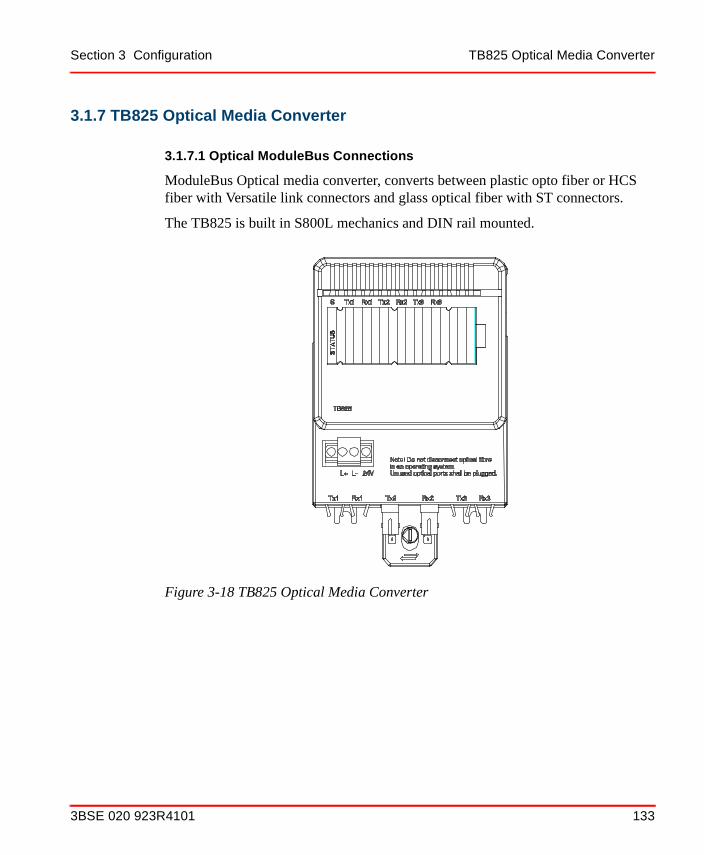
Section 3 Configuration TB825 Optical Media Converter
3.1.7 TB825 Optical Media Converter
3.1.7.1 Optical ModuleBus Connections
ModuleBus Optical media converter, converts between plastic opto fiber or HCS fiber with Versatile link connectors and glass optical fiber with ST connectors.
The TB825 is built in S800L mechanics and DIN rail mounted.
Figure 3-18 TB825 Optical Media Converter
3BSE 020 923R4101 133

TB825 Optical Media Converter Section 3 Configuration
Figure 3-19 ModuleBus configuration with Optical Media Converter TB825
FCI/Controller
TB820or
TB840
I/O I/O
TB825
1 2 3
Field fiber (duplex)
Local fiber (duplex)
TB825
1 2 3
TB820or
TB840
I/OI/O
Local fiber (duplex)
TB825
1 2 3
TB820or
TB840
I/OI/O
Local fiber (duplex)Field fiber (duplex)
Local fiber (duplex)
TB825
1 2 3
Local fiber (duplex)
TB820or
TB840
I/OI/O
TB820,TB840
orTB840A
TB820,TB840
orTB840A
TB820,TB840
orTB840A
TB820,TB840
orTB840A
Controller
134 3BSE 020 923R4101

Section 3 Configuration TB825 Optical Media Converter
3.1.7.2 Power Supply Connections
The TB825 requires 24 V d.c. (19.2 - 30 V) with a maximum current requirement of 0.1 Ampere.
3.1.7.3 Optical Fiber Connection
3.1.7.4 Calculation of Maximum Optical ModuleBus Configuration
The maximum signal delay should be calculated in the configuration. This is calculated using the signal path from the controller to the point in the configuration that has the longest delay. The maximum delay in a optical ModuleBus configuration must be ≤ 42 µs.
The delay values in Table 3-5 can be used to calculate the maximum delay in an optical ModuleBus configuration.
Table 3-3 TB825 Power Connection Terminal
Pin Designation Description
L+ L+ + 24 V d.c. Supply
L- L- 0 V d.c. Supply
Table 3-4 TB825 Optical Port Description
Connection Description
Tx1 Transmitting port local fiber 1
Rx1 Receiving port local fiber 1
Tx2 Transmitting port field fiber
Rx2 Receiving port field fiber
Tx3 Transmitting port local fiber 2
Rx3 Receiving port local fiber 2
3BSE 020 923R4101 135

TB825 Optical Media Converter Section 3 Configuration
Table 3-5 Delay Values Optical ModuleBus Components
Opto-to-opto delay in TB825(1) 2.4 µs
Opto-to-opto delay in TB820(1) 4.0 µs
Opto-to-electrical delay in TB820(1) 6.5 µs
Opto-to-opto delay in TB840/TB840A(1) 2.0 µs
Opto-to-electrical delay in TB840/TB840A(1) 5.5 µs
Delay in optical fiber(1)(2) (0.01 x length) µs
(1) Notice that the delays in the table is the sum of the communication delay in both directions, i.e. (delay of master frame) + (delay of slave frame).
(2) Total fiber length = total local fiber length + field fiber length
Figure 3-20 Example of worst case delay configuration
AC800
LF15 m
LF15 m
LF15 m
LF15 m
LF1.5 m
LF1.5 m FF
1000 m
LF1.5 m E
TB820
TB820
TB820
TB820
TB820
TB825
I/O
I/O
I/O
I/O
I/O
TB825 TB820 I/O
LF = Local fiberFF = Field fiberE = Electrical Modulebus
136 3BSE 020 923R4101

Section 3 Configuration Power Supply System
Calculation of the ModuleBus delay for the configuration in Figure 3-20:
ModuleBus delay = (total delay in optical fiber) + 5 x (opto-to-opto delay in TB820) + 2 x (delay in TB825) + (opto-to electrical delay in TB820) = (4 x 15 + 3 x 1.5 + 1000) x 0.01 + 5 x 4 + 2 x 2.4 + 6.5 = 42 µs.
3.2 Power Supply SystemThe power supply system for an S800 I/O system is very straightforward.
With the Type SD8xx series power supply modules, there is no requirement for the installation of a mains filter. Should other types of non-ABB power supply units be used, it may be necessary to install mains filters. For confirmation, refer to the relevant manufacturers documentation.
3.3 Powering S800 I/O SystemFigure 3-21 shows a series of simple circuit diagrams to indicate the various possibilities for connecting the incoming mains power supply, via the mains breaker, the power supply modules and the SS822 or SS823 voting devices, to the 24 V d.c. distribution terminals of the S800 I/O System.
3.4 Powering Field Equipment
3.4.1 Interference
Powering field equipment from a power supply located close to the S800 I/O system often requires the use of long 24 V d.c. cables which can easily pick up local interference and direct it straight back to the power supply modules.
3.4.2 Short-circuit at the output
The SD8xx series power supply has only a little extra energy reservoir at their outputs. In case of a short-circuit the output voltage of the power supply will fall rapidly.
Short-circuits, (even if fuses are installed in the 24 V d.c. distribution system), can produce unwanted voltage dips in the power supply. To avoid any influences on the
3BSE 020 923R4101 137

Sectioning the field equipment Section 3 Configuration
S800 I/O system from any of the field equipment, it is strongly recommended that independent power supply modules for both the S800 I/O system and the field equipment are installed.
3.4.3 Sectioning the field equipment
If the field equipment connected to an S800 I/O system are to be sectioned into groups so that a power fail in one group is not allowed to influence the power to other groups then it is recommended to use one power supply for each group of field equipment.
It is not safe to use fuses for sectioning in the 24 V d.c. distribution system. If a short-circuit occurs in one group the power supply voltage will most likely drop before any fuse is blown and consequently all groups will have a voltage drop in their supply. To work fairly the power supply must have a spare capacity of at least 3-4 times the rated current value of the lowest fuse connected to the power supply. The resistance of long cables can lead to problems.
3.4.4 Cable protection
Fuses in the 24 V d.c. distribution system for cable protection only can be used.
3.4.5 Connection alternatives
The power supply for field equipment can be connected in the same manner as that used for connecting and powering the S800 I/O system, see Figure 3-21.
It should be pointed out however, that the same Mains Breaker Unit can be used to control and isolate both power supplies or, alternatively, independent Mains Breakers can be used on each spur, see the examples shown in Figure 3-22.
138 3BSE 020 923R4101

Section 3 Configuration Connection alternatives
Figure 3-21 Power Supply Options for S800 I/O System
To
systemS800 I/O
Device 82x
SuppliesPower
Mains
24 V dcDistribution
SD Voting
Redundant Power Supplies
Redundant Mains Power Supplies
Terminals
24 V dcDistributionTerminals
24 V dcDistributionTerminals
82x
SupplyPower
SD
82xSD
82xSD
822(1)SS
823(2)SS
82xSD Mains
Mains 1
Mains 2
Mains Breaker
Mains Breaker
Mains Breaker
Mains Breaker
Single Power Supply
Power Supplies
To
systemS800 I/O
To
systemS800 I/O
Device Voting
823(2)SS
(1) or two SS823(2) or one SS822
3BSE 020 923R4101 139

Connection alternatives Section 3 Configuration
Figure 3-22 Powering Field Equipments
82xSD
82xSD
24 V dcDistribution
24 V dcDistribution
IndependentPower SupplyModules
82xSD
Mains
Mains Breaker
Mains Breaker
24 V dcDistribution
FieldEquipment24 V dcDistribution
Independent PowerSupply Modules
Independent MainsBreaker Units
SD82x
Mains Breaker
Mains
To
systemS800 I/O
To
equipmentField
To
systemS800 I/O
140 3BSE 020 923R4101

Section 3 Configuration Power Supply Load Calculation
3.5 Power Supply Load Calculation
3.5.1 Appropriate Hardware
Different power supply systems are available for the S800 I/O Station. The number of power supply units is calculated with respect to actual number of S800 I/O modules supported by the Station, see Section 3.9, Configuration for details.
Normally you don’t have to deal with current consumption calculations, however there are occasions with special requirements, or designs when detailed information regarding current consumption is valuable. Please find a description of special power supply usage under the guidelines below.
3.5.2 Guidelines
• A summary of the main requirements of the plant supply, from a planning point of view, is found in Section 2, Installation.
• Auxiliary equipment in the controlled system is normally powered separately from the S800 I/O power supplies.
• If field devices are grounded, be sure to use galvanic isolation.
• Heavy current on/off loads are always powered separately
• It is possible to use the system power supply for transmitters/transducers:
– There is idle capacity in the available power supply units
– The transducer is grounded directly in the control system chassis
3BSE 020 923R4101 141

Heat Dissipation Section 3 Configuration
3.6 Heat Dissipation
3.6.1 Cabinet Ventilation
To avoid overheating, when ambient temperatures are high, the heat dissipated in the electronics cabinet must be taken into consideration. This is particularly the case with sealed cabinets (IP54) or tropicalized cabinets (IP41).
The frequency of faults is estimated to be doubled for each 20°C increase in temperature. It is therefore important to maintain a low temperature where the equipment is installed.
The different hardware modules in the controller and the I/O system have different outputs of heat. Accurate calculation of the heat produced by the system requires knowledge of the modules and the work cycle.
3.6.2 Heat Dissipation Permitted in Cabinets
The maximum permitted temperature below the I/O station in the cabinet is 55 °C. The permissible amount of heat generated depends on the type of cabinet and its location.
In critical applications with an I/O station fully equipped and cabinets arranged in groups, it may be necessary to make a calculation of the actual power dissipation and an estimation of the temperature rise within the cabinet. It is recommended that you re-calculate when you expand the system as well.
3.6.3 Calculation of Heat Generated in a Cabinet
When calculating the heat generated in a cabinet, the heat generated by the different I/O modules must be summed, and then added to the heat generated by the power supply units and other equipment such as an extra modem, extra unit for supply of power to transmitters etc.
Section 3.10, Configuration gives the power dissipated as heat by hardware modules in the S800 I/O system.
142 3BSE 020 923R4101

Section 3 Configuration Maintenance and Repair
The total power dissipated in the cabinet can thus be written:
PFCI = Power of the FCI ModulePIO = Power of each S800 I/O Module PVoltagesupplyunit = Power loss of the power supply unit(s)PSundry = Miscellaneous power using equipment installed in the cabinet.
3.7 Maintenance and RepairFrom the maintenance point of view, use as few module types as possible in the hardware disposition of a control system. This is most relevant with the process I/O design. Standardization of I/O signal types and other electrical qualities is important to minimize the spare part stock.
Your solutions must make sense to the maintenance people in the event of disturbances and following trouble-shooting.
3.8 Expansion ConsiderationsA new S800 I/O station can be connected to an existing fieldbus without affecting other stations and controllers. The new I/O is automatically incorporated in the communication system. Spare connections must be pre-installed as to not disturb the existing bus.
The system fieldbus can be expanded in the following ways:
• Process I/O or MTU unit
New I/O modules can be added on line. It is recommended to have approximately 10 - 20% of total capacity as spare channels, and spare space.
Spare MTUs need to be pre-mounted to add I/O modules on-line.
PTotal PFCI∑( ) PIO∑( ) PVoltagesupplyunit∑( ) PSundry∑( )+ + +=
3BSE 020 923R4101 143

Power Supply Requirements Section 3 Configuration
3.9 Power Supply RequirementsA quick guide for power consumption to be used in a preliminary phase of a project work or whenever you need estimated figures is provided in Table 3-6.
3.9.1 Power Supply for DO880
To ensure bumpless performance of the I/O system including DO880, the power supply for the I/O field power should be able to support at least short circuit on one DO880 channel in addition to the total nominal load. Short circuit current for DO880 see technical data in S800 I/O Modules and Termination Units.
The following rules must be considered if ABB power supply units are being used together with DO880.
• When using power supply SD823 and the base load ≤ 16 A, two SD823 must be used in parallel.
• When using of SS823 the base load must not exceed 16 A.
Table 3-6 Estimated System Power Consumption
I/O Station24 V d.c. Power Consumption
Base Cluster (single FCI) and 6 I/O Modules 0.5 A
Base Cluster (single FCI) and 12 I/O Modules 1.0 A
Redundant FCIs (2) and 6 I/O Modules 1.0 A
Redundant FCIs (2) and 12 I/O Modules 1.5 A
Additional I/O Clusters and 6 I/O Modules 0.5 A
Additional I/O Clusters and 12 I/O Modules 1.0 A
The above estimates are based on an I/O Station with a mixed configuration of AI/AO and DI/DO. Only power consumption on the 24 V d.c. distributed via the ModuleBus are included. External 24 V connected directly to the I/O modules, for external loads and transmitters, are not included. When using large quantities of AO820s, DI885s, DO815s and/or DO820/DO821s, these load figures may be exceeded.
144 3BSE 020 923R4101
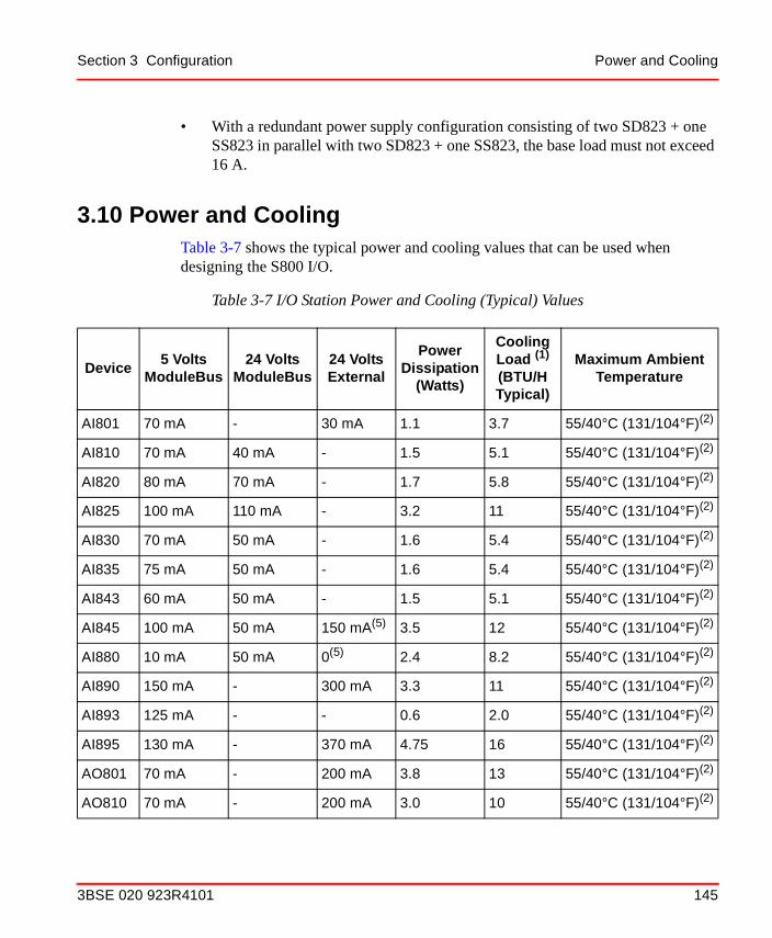
Section 3 Configuration Power and Cooling
• With a redundant power supply configuration consisting of two SD823 + one SS823 in parallel with two SD823 + one SS823, the base load must not exceed 16 A.
3.10 Power and CoolingTable 3-7 shows the typical power and cooling values that can be used when designing the S800 I/O.
Table 3-7 I/O Station Power and Cooling (Typical) Values
Device5 Volts
ModuleBus24 Volts
ModuleBus24 VoltsExternal
Power Dissipation
(Watts)
Cooling Load (1)
(BTU/H Typical)
Maximum Ambient Temperature
AI801 70 mA - 30 mA 1.1 3.7 55/40°C (131/104°F)(2)
AI810 70 mA 40 mA - 1.5 5.1 55/40°C (131/104°F)(2)
AI820 80 mA 70 mA - 1.7 5.8 55/40°C (131/104°F)(2)
AI825 100 mA 110 mA - 3.2 11 55/40°C (131/104°F)(2)
AI830 70 mA 50 mA - 1.6 5.4 55/40°C (131/104°F)(2)
AI835 75 mA 50 mA - 1.6 5.4 55/40°C (131/104°F)(2)
AI843 60 mA 50 mA - 1.5 5.1 55/40°C (131/104°F)(2)
AI845 100 mA 50 mA 150 mA(5) 3.5 12 55/40°C (131/104°F)(2)
AI880 10 mA 50 mA 0(5) 2.4 8.2 55/40°C (131/104°F)(2)
AI890 150 mA - 300 mA 3.3 11 55/40°C (131/104°F)(2)
AI893 125 mA - - 0.6 2.0 55/40°C (131/104°F)(2)
AI895 130 mA - 370 mA 4.75 16 55/40°C (131/104°F)(2)
AO801 70 mA - 200 mA 3.8 13 55/40°C (131/104°F)(2)
AO810 70 mA - 200 mA 3.0 10 55/40°C (131/104°F)(2)
3BSE 020 923R4101 145

Power and Cooling Section 3 Configuration
AO820 100 mA 260 mA - 6.0 20 55/40°C (131/104°F)(2)
AO845 125 mA - 165 mA 3.5 12 55/40°C (131/104°F)(2)
AO890 150 mA - 300 mA 3.5 12 55/40°C (131/104°F)(2)
AO895 130 mA - 330 mA 4.25 14.5 55/40°C (131/104°F)(2)
CI801 - - 140 mA 5.4 W(3) 19 55/40°C (131/104°F)(2)
CI810 - - 110 mA 2.6 8.9 55°C/(131°F)
CI820 - - 250 mA (4) 6.0 20 55°C/(131°F)
CI830 - - 110 mA 2.6 8.9 55°C/(131°F)
CI840 - - 190 mA(4) 7.7 26 55/40°C (131/104°F)(2)
DI801 70 mA - - 2.2 7.5 55/40°C (131/104°F)(2)
DI802 50 mA - - 2.8 9.6 55/40°C (131/104°F)(2)
DI803 50 mA - - 2.8 9.6 55/40°C (131/104°F)(2)
DI810 50 mA - - 1.8 6.1 55/40°C (131/104°F)(2)
DI811 50 mA - - 2.7 9.2 55/40°C (131/104°F)(2)
DI814 50 mA - - 1.8 6.1 55/40°C (131/104°F)(2)
DI820 50 mA - - 2.8 9.6 55/40°C (131/104°F)(2)
DI821 50 mA - - 2.8 9.6 55/40°C (131/104°F)(2)
DI825 90 mA - - 4.4 15 55/40°C (131/104°F)(2)
DI830 120 mA - - 2.3 7.8 55/40°C (131/104°F)(2)
DI831 120 mA - - 3.2 11 55/40°C (131/104°F)(2)
Table 3-7 I/O Station Power and Cooling (Typical) Values (Continued)
Device5 Volts
ModuleBus24 Volts
ModuleBus24 VoltsExternal
Power Dissipation
(Watts)
Cooling Load (1)
(BTU/H Typical)
Maximum Ambient Temperature
146 3BSE 020 923R4101
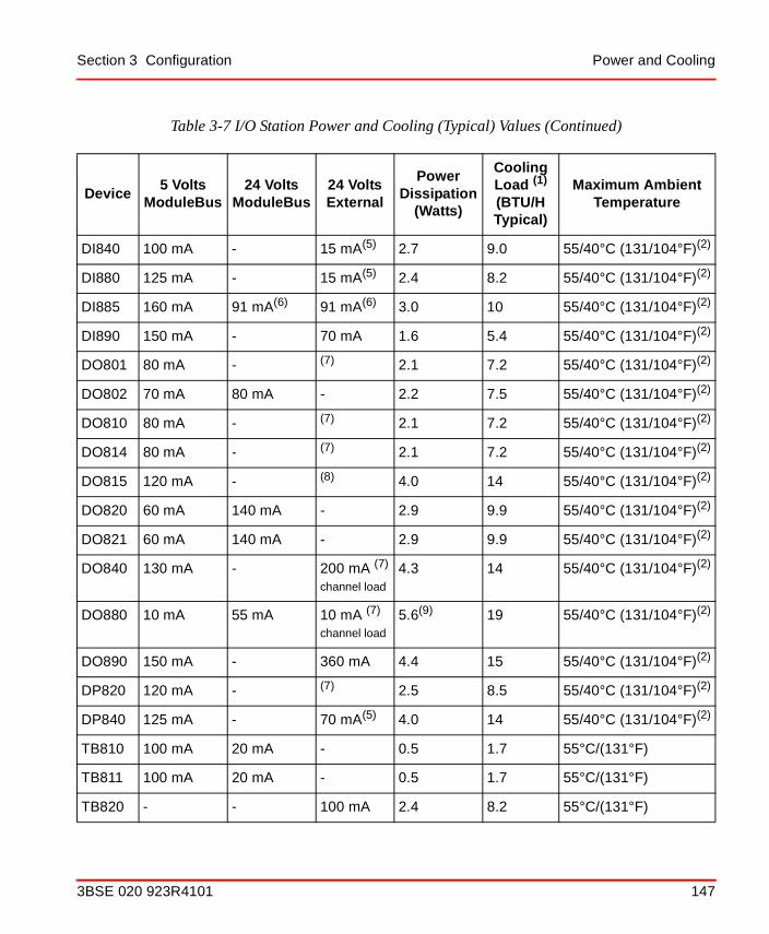
Section 3 Configuration Power and Cooling
DI840 100 mA - 15 mA(5) 2.7 9.0 55/40°C (131/104°F)(2)
DI880 125 mA - 15 mA(5) 2.4 8.2 55/40°C (131/104°F)(2)
DI885 160 mA 91 mA(6) 91 mA(6) 3.0 10 55/40°C (131/104°F)(2)
DI890 150 mA - 70 mA 1.6 5.4 55/40°C (131/104°F)(2)
DO801 80 mA - (7) 2.1 7.2 55/40°C (131/104°F)(2)
DO802 70 mA 80 mA - 2.2 7.5 55/40°C (131/104°F)(2)
DO810 80 mA - (7) 2.1 7.2 55/40°C (131/104°F)(2)
DO814 80 mA - (7) 2.1 7.2 55/40°C (131/104°F)(2)
DO815 120 mA - (8) 4.0 14 55/40°C (131/104°F)(2)
DO820 60 mA 140 mA - 2.9 9.9 55/40°C (131/104°F)(2)
DO821 60 mA 140 mA - 2.9 9.9 55/40°C (131/104°F)(2)
DO840 130 mA - 200 mA (7)
channel load
4.3 14 55/40°C (131/104°F)(2)
DO880 10 mA 55 mA 10 mA (7)
channel load
5.6(9) 19 55/40°C (131/104°F)(2)
DO890 150 mA - 360 mA 4.4 15 55/40°C (131/104°F)(2)
DP820 120 mA - (7) 2.5 8.5 55/40°C (131/104°F)(2)
DP840 125 mA - 70 mA(5) 4.0 14 55/40°C (131/104°F)(2)
TB810 100 mA 20 mA - 0.5 1.7 55°C/(131°F)
TB811 100 mA 20 mA - 0.5 1.7 55°C/(131°F)
TB820 - - 100 mA 2.4 8.2 55°C/(131°F)
Table 3-7 I/O Station Power and Cooling (Typical) Values (Continued)
Device5 Volts
ModuleBus24 Volts
ModuleBus24 VoltsExternal
Power Dissipation
(Watts)
Cooling Load (1)
(BTU/H Typical)
Maximum Ambient Temperature
3BSE 020 923R4101 147

Power and Cooling Section 3 Configuration
TB825 - - 96 mA 2.3 7.8 55°C/(131°F)
TB840 - - 120 mA(4) 6.0 20 55/40°C (131/104°F)(10)
TB842 100 mA 20 mA - 0.5 1.7 55°C/(131°F)
SD821 - - - 8.6 29 60°C/(140°F)(11)
SD822 - - - 13.3 45 60°C/(140°F)(11)
SD823 - - - 26.7 90 60°C/(140°F)(11)
SS822 - - - 2.5(12) 8.5 70°C/(158°F)(11)
SS823 - - - 24 82 70°C/(158°F)(11)
(1) Cooling load is the heat (BTU/H) produced by the equipment that may be required to meet room or enclosure cooling specifications.
(2) 40°C (104°F) applies to Compact MTUs with I/O modules, S800L, CI801 or CI840 mounted on a vertical DIN rail. (3) With maximum load at ModuleBus 24 V and 5V(4) In redundant configuration twice(5) + transducer power(6) 24 V from ModuleBus (91 mA) or 24 V external (91 mA) or 48 V external (22 mA).(7) 500 mA per channel with maximum load per channel. (8) 2 A per channel with maximum load per channel.(9) With maximum channel load(10) 40°C (104°F) mounter on a vertical DIN rail.(11) Horizontal mounting only.(12) 2,5 W at 5A, for calculation use W=0,5 V x Output current.
Table 3-7 I/O Station Power and Cooling (Typical) Values (Continued)
Device5 Volts
ModuleBus24 Volts
ModuleBus24 VoltsExternal
Power Dissipation
(Watts)
Cooling Load (1)
(BTU/H Typical)
Maximum Ambient Temperature
148 3BSE 020 923R4101

Section 3 Configuration Calculation of 24 V d.c. Power Consumption
3.10.1 Calculation of 24 V d.c. Power Consumption
Total 24 V d.c. power consumption = Σ 24 V load ModuleBus + Σ 5 V load ModuleBus*0.3 + Σ 24 V external load.
The calculated 24 V ModuleBus load should not exceed 1.4 A.
If too many of the modules: AO820, DO820 and DO821 are used, the maximum 24 V ModuleBus load could be exceeded. See Table 3-7 for exact data.
The calculated 5 V ModuleBus load should not exceed 1.5 A.
If too many of the modules: AI890, AI895, AO890, AO895, DI830, DI831, DI885, DI890, DO815, DO890 or DP820 are used, the maximum 5 v load could be exceeded. See table Table 3-7 for exact data.
3BSE 020 923R4101 149

Calculation of 24 V d.c. Power Consumption Section 3 Configuration
150 3BSE 020 923R4101

Section 4 Operation
4.1 Operating OverviewAn I/O station is an autonomous station, which is normally not handled by an operator. Of course, it is started and sometimes stopped manually. This is done in specific situations, for example during installation work and maintenance.
Consequently, operating instructions are spread out in this manual and will be discussed in the appropriate section.
For general descriptions, see the beginning of this section. For specific instructions, see Section 2, Installation and Section 5, Maintenance.
Please see the controller manual or the S800 I/O Fieldbus Communication Interface for PROFIBUS-DP or S800 I/O Fieldbus Communication Interface for Advant Fieldbus 100 manuals.
3BSE 020 923R4101 151

Operating Overview Section 4 Operation
152 3BSE 020 923R4101

Section 5 Maintenance
5.1 Preventive MaintenanceThis section describes routine maintenance, replacement and installation procedures necessary to maintain the operation of the S800 I/O equipment. The S800 I/O modules do not need special adjustments such as zero and span of analog I/O modules.
Analog I/O modules are factory calibrated and have calibration parameters for all ranges stored in memory on the module. The ModuleBus master uses those calibration parameters for calculations of the correct input and output signals.
Thermocouple and RTD modules use internal references for calibrations of the measured values.
5.2 Hardware IndicatorsVarious visual indications (LEDs) are used in the I/O-system for showing module status and for digital I/O modules also channel status.
These indications serve the purpose of informing the user about status or fault in the system or in the process. They are intended to be a simple and easy to use help. They should allow to spot faults in the station easily.
5.2.1 Color
A fixed meaning is assigned to the colors red, yellow and green:
RED Danger or alarmWarning of potential danger or a situation whichrequires immediate action
YELLOW Caution Change or impending change of condition, warning
3BSE 020 923R4101 153

Location Section 5 Maintenance
GREEN Safety Indication of a normal situation or authorization to proceed, clear way.
For digital I/O on-states a definite meaning can not be assigned. For them the color yellow is chosen. The Table 5-1 shows the meaning and colors of LED's.
5.2.2 Location
For the location of LEDs the following rules are applied:
S800 I/O Modules (except S800L)
• Indications having the same meaning on every I/O module (for example, FAULT, RUN, WARNING, OSP) are at the same position.
• The standard indications FAULT, RUN, WARNING and OSP (only output modules), are always on the topmost position on every device (top: FAULT, RUN, then WARNING, OSP).
S800L I/O Modules
• Have one LED S for module status showing FAULT (Red) or RUN (Green).
FCI
• On the FCI: FAULT, RUN, POWER OK, TRAFFIC and for redundant FCI also PRIMARY and DUAL.
Table 5-1 Meaning and Colors of LED’s
Meaning/Purpose Color Examples
Fault; Error Red "FAULT”
Warning, I/O State Indications and OSP (Outputs Set as Predetermined)
Yellow OSP, Process error,
Digital I/O on-state, Process voltage low, Traffic.
Normal Operation Green “RUN”, Normal operation, Power OK.
154 3BSE 020 923R4101

Section 5 Maintenance Identification
Optical ModuleBus Modem
• On TB820: FAULT, RUN, POWER OK, ORx1, ORx2 and ERx.
• On TB840: STATUS, POWER OK, Rx1, Rx2, ERx1 and ERx2.
5.2.3 Identification
LED's shall be identified by an appropriate symbol or abbreviation of an English term. For the standard indications the abbreviation is as follows:
• Fault in the module FAULT or F
• Device is in operation RUN or R
• External fault or minor fault in the module WARNING or W
• Output Set as Predetermined, OSP or O
• Digital I/O on-state 1, 2,... (channel number)
• Digital I/O channel FAULT or F
• Power supply ok internal and/or external ok POWER OK or P
• Module status (S800L modules and Optical ModuleBus Modem TB840) STATUS or S
• Traffic on Fieldbus TRAFFIC, T1, T2 or Rx/Tx
• Primary in redundant FCI configuration PRIMARY, PR or PRIM
• Both FCI in a redundant pair are in operation DUAL or DU
• Traffic on the Optical ModuleBus ORx1, ORx2, Rx1 or Rx2
• Traffic on the electrical ModuleBus. ERx, ERx1 or ERx2
5.3 Error MessagesNot applicable.
3BSE 020 923R4101 155

Fault Finding and User Repair Section 5 Maintenance
5.4 Fault Finding and User Repair
5.4.1 Introduction
Diagnostics are available in different forms for rapid localization of the source of the equipment malfunction. Hardware error is usually corrected by replacing the faulty module which is returned to ABB Service for repairs. The smallest replaceable unit is normally a module or an apparatus like a power supply unit.
Disturbances and system halt caused by software error is commonly solved by a manual system restart.
External faults in process wiring and transducers can also affect the function of the S800 I/O system. However, this type of fault is not discussed in this manual.
5.4.2 Diagnostics and Fault Indications
Hardware and software in a S800 I/O system is provided with supervision against system faults.
5.4.2.1 LED indicators on modules:
– Green LED, RUN, indicates normal function.
– Yellow LED indicates an active signal, for example, status of digital input (DI) or digital output (DO), OSP and Warning
– Red LED, FAULT, indicates malfunction
– Red/Green LED indicates module status (S800L modules)Red = FAULT, Green = RUN normal function.
5.4.3 List of General Fault Finding Procedures and Hints
5.4.3.1 Location of Malfunction
Sometimes, you lack the information from the controller diagnostics, that tells you where the fault is located. Suspicion about a fault is raised by the process behavior.
Experience indicates that approximately 85% of all faults occur in the process, 10% in the control program and 5% in the control system hardware.
156 3BSE 020 923R4101
Section 5 Maintenance List of General Fault Finding Procedures and Hints
It is always advisable to localize the malfunction with these figures in mind to minimize the down-time.
5.4.3.2 External Factors
In an electronics system which has given satisfactory service, most malfunctions have external causes. It is therefore important, when tracing a fault, to determine if any external factor such as incorrect handling of the equipment, short circuits, welding work, lightning strike and/or power failure has caused the malfunction.
5.4.3.3 Safety at Start/Stop
Voltage failure, component fault or manual restart usually affect the control system function. I/O system failure affects the process in different ways:
• In a system which is monitoring the process only, changes in the process status are not registered but there is no immediate danger to the process operation.
• In a system which is controlling a continuous processes (rolling mills and paper manufacture) demands a high degree of continuity of the control system functions.
5.4.3.4 Check of Non-redundant Power Supply
The CI801/CI810/CI820/CI830/CI840 Fieldbus Communications Interface (FCI), or TB820/TB840/TB840A status LED - P is illuminated when 24 V d.c. is supplied to the FCI or TB820/TB840/TB840A, and 5 V (from the FCI or TB820/TB840/TB840A) is supplied to the rest of the I/O Station.
The supply system consists at least of one power supply.
Power can be checked at the FCI or TB820/TB840/TB840A on terminals L+ and L- with a voltmeter. The value should be 24 V d.c. (19.2 to 30). Power can also be checked at the power supply or on the distribution strip.
A restart of the I/O system or controller can have very serious consequences. It is important to be aware of the local requirements for safety when starting and stopping the I/O system or controller.
3BSE 020 923R4101 157
User Repair Section 5 Maintenance
5.4.3.5 Check of Redundant Power Supply
The CI801/CI810/CI820/CI830/CI840 Fieldbus Communications Interface (FCI), or TB820/TB840/TB840A status LED - P is illuminated when 24 V d.c. is supplied to the FCI/TB820/TB840/TB840A, and 5 V (from the FCI/TB820/TB840/TB840A) is supplied to the rest of the I/O Station.
The supply system consists of at least two power supplies.
Power can be checked at the FCI or TB820/TB840/TB840A on terminals L+ and L- with a voltmeter. The value should be 24 V d.c. (19.2 to 30). Power can also be checked at the power supplies, diode unit or on the distribution strip.
To do a complete check each power supply has to be run as single.
5.4.4 User Repair
5.4.4.1 I/O Module Replacement
All S800 I/O modules, except for the S800L modules or relay output modules with normally closed contacts, can be exchanged on-line with the process power supply connected. This is possible because the module deactivates when the I/O module lock switch is turned to unlock.
It is important to understand the consequences of a module exchange on-line and how it affects the process. Replacement of an S800 I/O module affects all channels on the module. It also sometimes indirectly affects the outputs via some application function, on another module.
To exchange a S800L module or MTU the power supply must be switched off.
The system software in the ModuleBus master checks automatically that all I/O modules function correctly. In the event of module fault, and module exchange, the module and associated signals are marked as faulty.
The system software checks that the module is inserted and correct. If this is the case, the Fault-indicator (LED) extinguishes (after 10 seconds).
Switch off the process voltage before removal of the module, if the plastic cover for the I/O modules DI802, DI803, DI820, DI821, DO802, DO820 or DO821 is damaged, and there is risk for contact with live parts.
158 3BSE 020 923R4101

Section 5 Maintenance User Repair
5.4.4.2 Power Supply Module Replacement
In single or parallel operation of power supplies, there will always be a disturbance of the function when a power supply must be replaced; the station will not have power.
In a redundant power supply configuration, it is possible to replace a power supply module without disturbance of the function. To achieve that installation, see Figure 3-21 and Figure 3-22 and the correct replacement procedure that follows.
Practical Execution
Replace faulty or suspect power supply module in the following way:For single or parallel operation do steps 1, 2 and 4 to13.For redundant configuration do steps 1 to 14.
1. Read Section 2, Installation.
2. Check that the new module can replace the old.
3. Switch off the output from the module (only redundant configuration).
4. Switch off input power to the module.
5. Disconnect the wires.
6. Dismount the module by loosening the module locking.
7. Mount the new module.
8. Connect the input wires.
9. Switch on input power to the module.
10. Perform a function test on the new module.
11. Switch off input power to the module.
12. Connect the output wires.
13. Switch on input power to the module.
14. Switch on the output from the module (only redundant configuration).
3BSE 020 923R4101 159

User Repair Section 5 Maintenance
5.4.4.3 Communication Module Replacement
Normally communications modules can’t be exchanged on-line, the only exception are the CI820/CI840/TB840/TB840A in a redundant configuration.
It is important to understand the consequences of a module exchange and how it affects the process.
• Replacement of a communication module type CI801/CI810/CI820/CI830 or a CI840 in a single configuration affects all channels on all the modules in an I/O station. The station will loose power.
• Replacement of a single communication module type CI820/CI840 in a redundant configuration has no affects on channels in an I/O station.
• Replacement of a communication module type TB810/TB811/TB842 affects all channels on all the modules in all clusters except cluster 0. The communication will be broken to all clusters except for cluster 0.
• Replacement of a communication module type TB815 affects all channels on all the modules in an I/O station. The station will loose power.
• Replacement of a communication module type TB820, TB840 or TB840A in a single configuration, connected via a simplex optical cable, affects all channels on all the modules in all clusters except cluster 0. The communication will be broken to all clusters except for cluster 0. The cluster where the TB820/TB840/TB840A should be replaced will be power less.
• Replacement of a communication module type TB820, TB840 or TB840A in a single configuration, connected via a duplex optical cable, affects all channels on all the modules in all clusters after and including the cluster where the replaced TB820/TB840/TB840A is located. The communication will be broken to all clusters after where the replaced TB820/TB840/TB840A is located. The cluster where TB820/TB840/TB840A should be replaced will be power less.
• Replacement of a communication module type TB840/TB840A in a redundant configuration has no affects on channels in an I/O station.
If TB842 should be replaced in a running system the carrier (TB806 or TB846) of TB842 have to be disconnected from the FCI first.
160 3BSE 020 923R4101
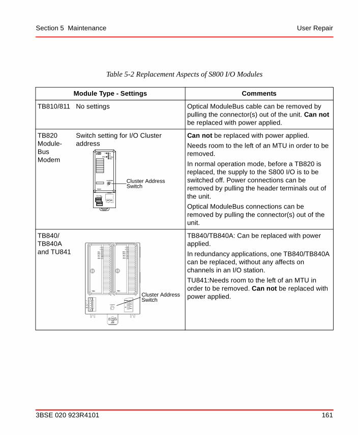
Section 5 Maintenance User Repair
Table 5-2 Replacement Aspects of S800 I/O Modules
Module Type - Settings Comments
TB810/811 No settings Optical ModuleBus cable can be removed by pulling the connector(s) out of the unit. Can not be replaced with power applied.
TB820Module-Bus Modem
Switch setting for I/O Cluster address
Can not be replaced with power applied.
Needs room to the left of an MTU in order to be removed.
In normal operation mode, before a TB820 is replaced, the supply to the S800 I/O is to be switched off. Power connections can be removed by pulling the header terminals out of the unit.
Optical ModuleBus connections can be removed by pulling the connector(s) out of the unit.
TB840/TB840A and TU841
TB840/TB840A: Can be replaced with power applied.
In redundancy applications, one TB840/TB840A can be replaced, without any affects on channels in an I/O station.
TU841:Needs room to the left of an MTU in order to be removed. Can not be replaced with power applied.
12
75
34 6
CLUSTER
SBSA
L-L+L+
L-
F R
ORx2ORx1P
TB820
ERx
Cluster AddressSwitch
X4 X5Rx TxRx Tx
Cluster AddressSwitch
3BSE 020 923R4101 161

User Repair Section 5 Maintenance
TB842 No settings Optical ModuleBus cable can be removed by pulling the connector(s) out of the unit. Can be replaced with power applied.
If TB842 should be replaced in a running system the carrier (TB806 or TB846) of TB842 have to be disconnected from the FCI first.
TU841 See TB840
Table 5-2 Replacement Aspects of S800 I/O Modules (Continued)
Module Type - Settings Comments
162 3BSE 020 923R4101

Appendix A General Specifications
A.1 Standards and ApprovalsPlease check how the approvals are applicable for each module.
A.1.1 Electrical Safety Standards and Approvals
EN 3810 Electronical and Electrical Test, Measuring and Process Control Equipment
EN 50178 Electronic Equipment for Use in Power Installations
IEC 601131-2 Programmable Controllers Part 2: Equipment Requirements and Tests
EN 601131-2 Programmable Controllers Part 2: Equipment Requirements and Tests
UL 508 Industrial Control Equipment.
CSA 22.2 No.142-M1987 Process Control Equipment. Industrial Products
3BSE 020 923R4101 163

Hazardous Classified Locations Appendix A General Specifications
A.1.2 Hazardous Classified Locations
A.1.3 CE-marking
S800 products fulfill the requirements of EU-directives 89/336/EEC "Electromagnetic Compatibility" (EMC Directive) and 72/23/EEC "Electrical Equipment Designed for Use between Certain Voltage Limits" (Low Voltage Directive). Declarations of conformity are available on request.
CSA 22.2 No.213-M1987 Non-Incendive Electrical Equipment for use in Class 1, Division 2 Hazardous Locations
FM 3600 Electrical Equipment for use in Hazardous (Classified) locations
FM 3611 Non-Incendive Electrical Equipment for use in Class 1, Division 2 Hazardous Locations
UL 1604 Electrical Equipment for use in Class 1, Division 2 and Hazardous Locations
164 3BSE 020 923R4101

Appendix A General Specifications Transport and Storage Conditions
A.2 Transport and Storage ConditionsS800 modules should be transported and stored in their original packaging.
Condition Range Standard
Temperature -25 to +70°C IEC/EN 61131-2
Humidity RH = 5 to 95%, no condensation
Altitude -500 to +3000 m
Pollution degree Degree 2 IEC 60664-1
Corrosive atmosphere
1000 Angstrom copper corrosion over 28 days
ISA 71.04 Class G2
Fall in package < 10 kg: 300 mm10 - 40 kg: 300 mm> 40 kg: 250 mm
Free-fall drop height in original product package.
Shock 150 m/s2, 11 ms
3BSE 020 923R4101 165

Climatic operating conditions Appendix A General Specifications
A.3 Climatic operating conditions
A.4 Mechanical operating conditions
Condition Operative range Standard
Temperature(1)
(1) Approvals are issued for +5 to +55°C.
0 to +55°C non-condensing0 to +40°C compact MTUs or S800L modules on vertical DIN-rail, see Table 3-7, non-condensing
IEC/EN 61131-2
Temperature change
3 °C/min
Humidity RH = 5 to 95%, no condensation
Altitude 2000 m
Pollution degree Degree 2 IEC 60664-1
Corrosive atmosphere
1000 Angstrom copper corrosion over 28 days
ISA 71.04 class G2
Operative range Standard
Vibration, three axisSinusoidal, 10<f<50 Hz
Continuous: 0.0375 mm amplitudeOccasional: 0.075 mm amplitude
IEC/EN 61131-2
Sinusoidal, 50<f<150Hz
Continuous 0,5 gOccasional: 1,0 g
Shock 150 m/s2, 11 ms
Emitted noise <55 dB (A)
166 3BSE 020 923R4101

Appendix A General Specifications EMC
A.5 EMC
Radiated Radio Frequency Emission IEC/EN 61000-6-4 (Class A), IEC/EN 61131-2
Test Limits Generic standards
30 MHz -230 MHz 40 dB (µV/m) quasi peak EN 55011,CISPR 11
230 MHz - 1000 MHz
47 dB (µV/m) quasi peak
Conducted Radio Frequency Emission, AC mains port IEC 61000-6-4 (Class A), IEC/EN 61131-2
Test Limits Generic standards
0,15 MHz -0,50 MHz
79 dB (µV/m) quasi peak66 dB (µV/m) average
EN 55011,CISPR 11
0,50 MHz - 5 MHz 73 dB (µV) quasi peak60 dB (µV/m) average
5 MHz - 30 MHz 73 dB (µV) quasi peak60 dB (µV/m) average
Immunity IEC/EN 61000-6-2, IEC/EN 61131-2 Continuous...
Test Severity Generic standards
Radiated RF field 10 V/m IEC/EN 61000-4-3
Conducted RF field 10 V IEC/EN 61000-4-6
3BSE 020 923R4101 167

Overvoltage Categories Appendix A General Specifications
A.5.1 Overvoltage Categories
Transients immunity
Electrostatic discharge
4 kV contact discharge 8 kV air discharge
IEC/EN 61000-4-2
Electrical fast transient/Burst
4 kV, power supply2 kV, power ports1 kV, power ports1 kV, other lines
IEC/EN 61000-4-4
Surge 4 kV, common mode, power supply2 kV, differential mode, power supply2 kV, common mode, P I/O, Com.1 kV, differential mode, P I/O, Com.
IEC/EN 61000-4-5
Power frequency magnetic field
30 A/m, cont.3 A/m for CRTs
IEC/EN 61000-4-8
Installation type Category Standards
Equipment permanently connected to low voltage mains
Overvoltage categories III IEC/EN 60664-1, EN 50178
Equipment not energized directly from the low voltage mains
Overvoltage categories II
168 3BSE 020 923R4101

Appendix A General Specifications Equipment Class and Insulation Voltages
A.6 Equipment Class and Insulation Voltages
A.6.1 Overvoltage Categories According to IEC 60664-1
AC mains power supplies are compliant with Overvoltage Category III networks (industrial mains). All I/O signals are overvoltage II compliant.
A.6.2 Equipment Class
S800 equipment class is Class 1 according to IEC 60536. Class 1 means protection of electric shock by protective earth connection (PE). In this case this means a PE- connection must be made to the DIN rail.
A.6.3 Insulation Voltage
All accessible ports on S800 modules are galvanically isolated from ground and system. For actual module isolation configuration, please consult module data sheets.
A.6.4 Insulation Test Voltage
Type test, insulation test voltage:
500 V a.c. or 700 V d.c. 1 minute for RIV 50V1 modules
2000 V a.c. 1 minute for RIV 250V modules
Routine Test, insulation test voltage:
850 V d.c. 1 second for RIV 50V modules
2000 V a.c. 1 second for RIV 250V modules
1. Modules with a working voltage of less than 50 V have RIV 50 V. RIV 250 V applies to all modules having a working voltage greater than 50 V. It should be noted that insulation test voltage specifications, according to electrical safety standards, do not imply that permanent connection to circuits with voltages greater than the specified Rated Insulation Voltage is allowed. Connection to voltages higher than specified RIV violates electrical safety codes and may expose users to electric shock.
3BSE 020 923R4101 169

Insulation Test Voltage Appendix A General Specifications
170 3BSE 020 923R4101

Appendix B Specifications
B.1 SD821/SD822/SD823 Power Supply Modules, 24 V d.c.
B.1.1 Key Features
• Simple DIN-rail mounting
• Parallel connection permitted for load sharing
• Class I Equipment, (when connected to Protective Earth, (PE))
• Over-voltage Category III for connection to primary main TN network of Installation Category III
• Protective separation of secondary circuit from primary circuit.
• Secondary outputs;
– SD823 = 24 Volts d.c. regulated @ 10 A
– SD822 = 24 Volts d.c. regulated @ 5 A
– SD821 = 24 Volts d.c. regulated @ 2.5 A
• Accepted for SELV and PELV applications
B.1.2 Equipment Class
The Power Supply Units, (PSU), are designed to meet all the applicable electrical safety data stated by the EN 50178 harmonized European Standard Publication and the additional safety and function data required by EN 61131-2 and UL 508.
The secondary output circuitry is accepted for SELV or PELV applications.
SELV according to EN 50178, EN 60950 and VDE 0100 Part 410.
For PELV applications; in accordance with EN 50178.
3BSE 020 923R4101 171

SD821/SD822/SD823 Power Supply Modules, 24 V d.c. Appendix B Specifications
B.1.3 Ingress Protection
IP20 according to EN 60529, IEC 60529
Protective Class I according to EN 50718; 3.56
172 3BSE 020 923R4101

Appendix B Specifications SD821/SD822/SD823 Power Supply Modules, 24 V d.c.
Figure B-1 SD821 Connections for 2.5 A Power Supply
L+ L+ L- L-
N L
103
125
50
44
97
PE
OK
SD821
110
230Mains VoltageSelection Switch(115 / 230)
3BSE 020 923R4101 173
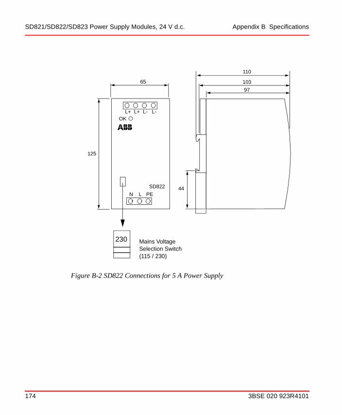
SD821/SD822/SD823 Power Supply Modules, 24 V d.c. Appendix B Specifications
Figure B-2 SD822 Connections for 5 A Power Supply
103
44
97
110
L+ L+ L- L-
N L
125
65
PE
OK
SD822
230 Mains VoltageSelection Switch (115 / 230)
174 3BSE 020 923R4101

Appendix B Specifications SD821/SD822/SD823 Power Supply Modules, 24 V d.c.
Figure B-3 SD823 Connections for 10 A Power Supply
103mm (4.1")
44m
m
97mm (3.8")
110mm (4.3")
L+ L+ L- L-N L
120mm (4.7")
PEOK
SD823
115V230V
125m
m(4
.9")
(1.7
")
3BSE 020 923R4101 175

Power Supply Units Types SD821 / 822 / 823 - Description Appendix B Specifications
B.1.4 Power Supply Units Types SD821 / 822 / 823 - Description
ABB recommend the use of these robust and reliable power supply units, (PSUs), for providing power to the S800I/O system, when connected to an industrial mains network of installation category III. PSUs can be used for both non-redundant and redundant applications, as well as parallel connection for more output power. In parallel connection the life time will decrease due to not perfect load sharing. One power supply will put out max current and the rest by the other.
To get a better load sharing the output voltage from the power supply units (only SD823) should be adjusted to the same value. Each power supply should be connected to the load via a cable of same area and length as the others. The length should be ≥ 1 m and the area not bigger than necessary.
The three PSUs were designed as switch mode power converters, that is, converting a.c. mains supply voltage to a regulated 24 V d.c. output. The three converters have rated output capacities as follows:
• SD823 = 24 Volts d.c. regulated @ 10 A
• SD822 = 24 Volts d.c. regulated @ 5 A
• SD821 = 24 Volts d.c. regulated @ 2.5 A
The mains input voltage is set to either 115 V or 230 V by means of a switch mounted on the front face of the module. The factory default for this switch is in the 230 V position.
The output voltage of all three PSUs is, as stated, a regulated, low noise, 24 V d.c. A green LED, mounted on the PSU front panel, indicates that the output circuit is providing the correct output voltage level. The double connectors, provided on the 24 V d.c. output terminals, allow for the connection of more than one equipment.
A surge current limiter within the PSU circuit, provides a soft-start feature. The controlled power-on of a PSU therefore, will not trip fuses or earth-fault circuit breakers. In addition, the normal disturbances that occur within an industrial main network will not cause any transient fault conditions or trips to occur.
This means that the surge current limiter will effectively reduce the peak inrush current, caused by a power disruption, to a level that the PSU can tolerate.
This soft-start, surge current limiter facility provides ease of design for the system power distribution circuits.
176 3BSE 020 923R4101

Appendix B Specifications Power Supply Units Types SD821 / 822 / 823 - Description
B.1.5 Insulation of Power Supply Units (PSU)
Basic with protective conductor. The primary circuit is separated from all other live circuits by reinforced insulation.
Rated insulation voltage Primary to Secondary 300 V a.c.
Dielectric test voltage 3000 V a.c. (EN 60950).
Figure B-4 PSUs SD821, 822 and 823 - Block Diagram
L
N
PE
L+
L+
L-
LED
Chopper
Fuse
L-
X1 X2
3BSE 020 923R4101 177
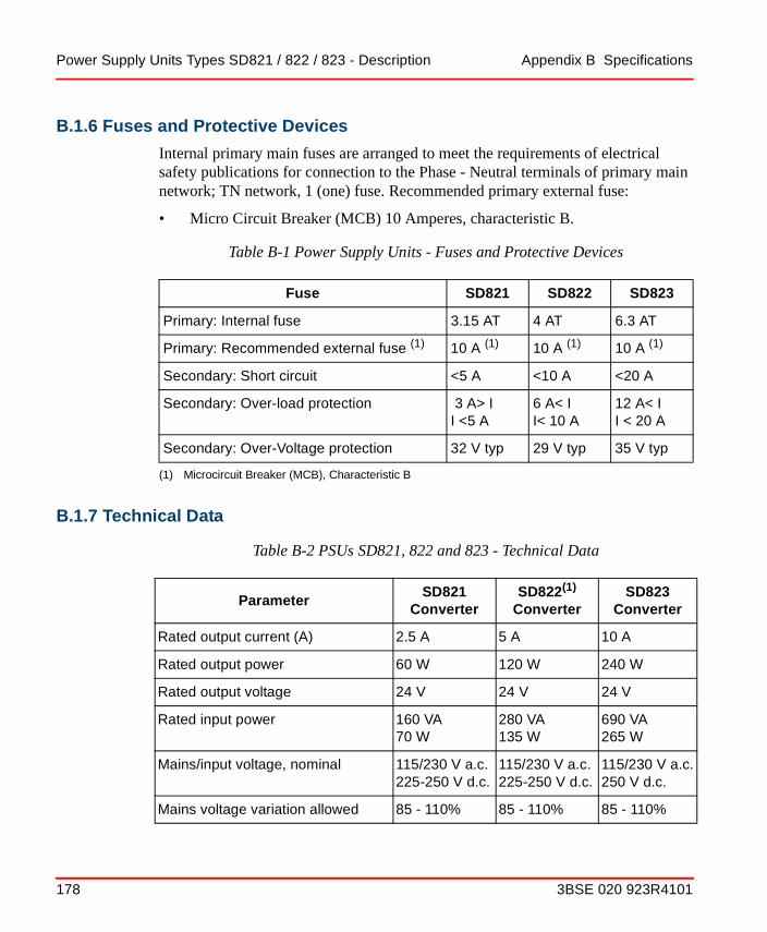
Power Supply Units Types SD821 / 822 / 823 - Description Appendix B Specifications
B.1.6 Fuses and Protective Devices
Internal primary main fuses are arranged to meet the requirements of electrical safety publications for connection to the Phase - Neutral terminals of primary main network; TN network, 1 (one) fuse. Recommended primary external fuse:
• Micro Circuit Breaker (MCB) 10 Amperes, characteristic B.
B.1.7 Technical Data
Table B-1 Power Supply Units - Fuses and Protective Devices
Fuse SD821 SD822 SD823
Primary: Internal fuse 3.15 AT 4 AT 6.3 AT
Primary: Recommended external fuse (1)
(1) Microcircuit Breaker (MCB), Characteristic B
10 A (1) 10 A (1) 10 A (1)
Secondary: Short circuit <5 A <10 A <20 A
Secondary: Over-load protection 3 A> I I <5 A
6 A< II< 10 A
12 A< II < 20 A
Secondary: Over-Voltage protection 32 V typ 29 V typ 35 V typ
Table B-2 PSUs SD821, 822 and 823 - Technical Data
ParameterSD821
ConverterSD822(1)
ConverterSD823
Converter
Rated output current (A) 2.5 A 5 A 10 A
Rated output power 60 W 120 W 240 W
Rated output voltage 24 V 24 V 24 V
Rated input power 160 VA70 W
280 VA135 W
690 VA265 W
Mains/input voltage, nominal 115/230 V a.c.225-250 V d.c.
115/230 V a.c.225-250 V d.c.
115/230 V a.c.250 V d.c.
Mains voltage variation allowed 85 - 110% 85 - 110% 85 - 110%
178 3BSE 020 923R4101

Appendix B Specifications Power Supply Units Types SD821 / 822 / 823 - Description
Mains/input voltage, max. (a.c.= 45-65 Hz)
138/275 V a.c.375 V d.c.
138/275 V a.c.375 V d.c.
138/275 V a.c.375 V d.c.
Surge; Primary peak current at power on
25 A 15 A 30 A
Power Factor (at rated output power)
0.47 typ 0.5 typ 0.5 typ
Heat dissipation 8.6 W 13.3 W 26.7 W
Efficiency factor 87% typ 90% typ 90% typ
Output voltage regulation at max. current
+-2% +-2% +-2%
Ripple (peak to peak) 25 mV 25 mV 30 mV
Secondary voltage holdup time at mains blackout
>20 ms >20 ms >20 ms
Maximum output current 5 A 10 A 20 A
Maximum ambient temperature 60oC(2) 70oC(2) 60oC(2)
(1) SD822Z is G3 compliant version according to ISA-S71.04.(2) Mounting on a horizontal DIN rail
Table B-3 PSUs SD821, 822 and 823 - Mounting Dimensions
ParameterSD821
ConverterSD822
ConverterSD823
Converter
Dimensions, Width
HxD = 125 x 110 mm (4.9” x 4.3”)
50 mm (2.0”) 65 mm (2.6”) 120 mm (4.7”)
Mounting spacing W mm 10 mm (0.4”) 15 mm (0.6”) 15 mm (0.6”)
Table B-2 PSUs SD821, 822 and 823 - Technical Data (Continued)
ParameterSD821
ConverterSD822(1)
ConverterSD823
Converter
3BSE 020 923R4101 179

Power Supply Units Types SD821 / 822 / 823 - Description Appendix B Specifications
Mounting spacing H mm 25 mm (1.0”) 25 mm (1.0”) 25 mm (1.0”)
Weight (lbs.) 460 g (1.0 lbs.)
620 g (1.4 lbs.)
980 g (2.2 lbs.)
Table B-3 PSUs SD821, 822 and 823 - Mounting Dimensions (Continued)
ParameterSD821
ConverterSD822
ConverterSD823
Converter
180 3BSE 020 923R4101

Appendix B Specifications Power Supply Units Types SD821 / 822 / 823 - Description
B.1.8 Connection Diagram
The diagram shows the connections needed for parallel operation.For redundant operation, see SS822 Voting Unit - (for Redundant Power Supply) on page 182 and SS823 Power Voter Unit - (for Redundant power Supply) on page 186.
Figure B-5 SD821 - Used in Parallel Configuration.
L+ L+ L- L-
N L PE
OK
SD821
L+ L+ L- L-
N L PE
OK
SD821
MainsInput
Protective Earth
L +
L -
+ 24V
+ 0V
3BSE 020 923R4101 181

SS822 Voting Unit - (for Redundant Power Supply) Appendix B Specifications
B.2 SS822 Voting Unit - (for Redundant Power Supply)
B.2.1 Redundant Power Supply Configurations
The SS822 Voting Unit has been specifically designed to be employed as a control unit within a redundant power supply configuration. The output connections from two identical Power Supply Units, (PSUs), are connected to the SS822 Voting Unit.
The SS822 Voting Unit separates the redundant PSUs, supervises the voltage supplied, and generates supervision signals to be connected to the computer system. Green LED’s, mounted on the front panel of the SS822, provide a visual indication that the correct output voltage is being delivered. Simultaneously with the green LED illuminating, a voltage free contact closes the path to the corresponding “OK connector”. SS822 Voting Unit trip level’s, (2 off), are factory preset, see Table B-4 SS822 Voting Unit - Supervision Data, for details.
Figure B-6 SS822 Block Diagram
B+
L-
L+
OK
F
+
OK
F
+
B+
A+
A+
L+
X1 X2
A
B
182 3BSE 020 923R4101
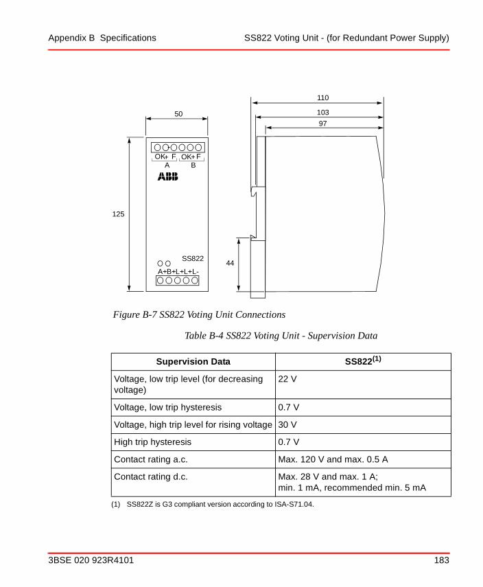
Appendix B Specifications SS822 Voting Unit - (for Redundant Power Supply)
Figure B-7 SS822 Voting Unit Connections
Table B-4 SS822 Voting Unit - Supervision Data
Supervision Data SS822(1)
(1) SS822Z is G3 compliant version according to ISA-S71.04.
Voltage, low trip level (for decreasing voltage)
22 V
Voltage, low trip hysteresis 0.7 V
Voltage, high trip level for rising voltage 30 V
High trip hysteresis 0.7 V
Contact rating a.c. Max. 120 V and max. 0.5 A
Contact rating d.c. Max. 28 V and max. 1 A; min. 1 mA, recommended min. 5 mA
125
50
OK F OK
A+B+L+
SS822
F+ +A B
L+L-
103
44
97
110
3BSE 020 923R4101 183

SS822 Voting Unit - (for Redundant Power Supply) Appendix B Specifications
Table B-5 SS822 - Technical Data and Mounting Dimensions
Parameter SS822 Voter
Rated output current (A) 20 A
Rated output voltage 35 V
Rated input power 500 W
Mains/input voltage, nominal 2 x 24 V d.c.
Rated/input voltage 35 V d.c.
Heat dissipation 10 W at 20 A and 2,5 W at 5 A
Output voltage regulation at max. current
0,5 V lower than input
Maximum output current 35 A (Overload)
Ingress Protection IP20 according to EN60529, IEC 60529.
Max ambient temperature 70oC(1)
(1) Mounting on a horizontal DIN rail
Dimensions, Width
HxD = 125 x 110 mm(4.9 x 4.3 inches)
50 mm (2.0”)
Mounting spacing W mm 10 mm (0.4”)
Mounting spacing H mm 25 mm (1.0”)
Weight (lbs.) 630 g (1.4 lbs.)
184 3BSE 020 923R4101
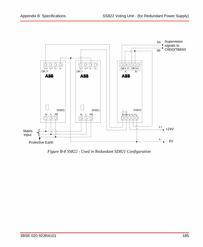
Appendix B Specifications SS822 Voting Unit - (for Redundant Power Supply)
Figure B-8 SS822 - Used in Redundant SD821 Configuration
OK F OK
A+B+L+
SS822
F+ +A B
L+L-
L+ L+ L- L-
N L PE
OK
SD821
L+ L+ L- L-
N L PE
OK
SD821
SA
SB
L-
L+
Supervisionsignals toCI8X0/TB8X0
+24V
0V
MainsInput
Protective Earth
3BSE 020 923R4101 185

SS823 Power Voter Unit - (for Redundant power Supply) Appendix B Specifications
B.3 SS823 Power Voter Unit - (for Redundant power Supply)
B.3.1 Redundant Power Supply Configurations
The SS823 Power Voter Unit has been specifically designed for utilization as a control unit within a redundant power supply configuration. The output connections from two identical Power Supply Units, (PSUs), are connected to the SS823 Power Voter Units, see Figure B-11.
The SS823 Voting Units separates the redundant PSUs, supervises the voltage supplied, and generates supervision signals to be connected to the computer system.
Green LED’s, mounted on the front panel of the SS823, provide a visual indication that the correct output voltage is being delivered. Simultaneously with the green LED illuminating, a voltage free contact closes the path to the corresponding “OK connector”. SS823 Power Voter Unit trip level, is factory preset, see Table B-6 SS823 Power Voter Unit - Supervision Data, for details.
The SS823 Voting Unit has double overvoltage protection circuit on both inputs. It is also able to detect both short and open circuit in the voting element. For details see Table B-7.
Two SS823 can never be configured in parallel to achieve more current.
186 3BSE 020 923R4101

Appendix B Specifications SS823 Power Voter Unit - (for Redundant power Supply)
Figure B-9 SS823 Block Diagram
3BSE 020 923R4101 187

SS823 Power Voter Unit - (for Redundant power Supply) Appendix B Specifications
Figure B-10 SS823 Power Voter Unit Connections
Table B-6 SS823 Power Voter Unit - Supervision Data
Supervision Data SS823
Voltage, low trip level (for decreasing voltage)
22 V
Voltage, low trip hysteresis 0.7 V
Voltage, high trip level for rising voltage 30 V
High trip hysteresis 0.7 V
Contact rating a.c. Max. 120 V and max. 0.5 A
Contact rating d.c. Max. 28 V and max. 1 A; min. 1 mA, recommended min. 5 mA
188 3BSE 020 923R4101

Appendix B Specifications SS823 Power Voter Unit - (for Redundant power Supply)
Table B-7 SS823 - Technical Data and Mounting Dimensions
Parameter SS823 Voter
Rated output current (A) 20 A
Rated output voltage 24 V
Rated input power 500 W
Mains/input voltage, nominal 24 V d.c.
Mains/input voltage, max 30 V d.c.(1)
(1) Electronically limited by OVP, voltage between 32 V and 60 V will result in 0 V output
Dual level OVP (Overvoltage protection)
Trip 32.0 V nominalReturn 31.5 V nominal
Heat dissipation 24 W max
Output voltage regulation at max. current
1.2 V lower than input
Maximum output current Static 35 A typical, dynamic 150 A for 100 µs typical
Ingress Protection IP20 according to EN60529, IEC 60529.
Max ambient temperature 70oC(2)
(2) Mounting on a horizontal DIN rail
Mounting spacing W mm 15 mm (0.59”)
Mounting spacing H mm 25 mm (1.0”)
Width 140 mm (5.51”)
Depth 144 mm (5.67”
Height 174 mm (6.85”)
Weight 800 g (1.8 lbs.)
3BSE 020 923R4101 189

SS823 Power Voter Unit - (for Redundant power Supply) Appendix B Specifications
Figure B-11 SS823 - Used in Redundant SD821 Configuration
SASB
L+L-
From MainsBreaker
From MainsBreaker
190 3BSE 020 923R4101

Appendix B Specifications TB805/TB806 ModuleBus Cable Adapter-Out/In
B.4 TB805/TB806 ModuleBus Cable Adapter-Out/In
B.4.1 Features
• Passive unit used for connection and extension of the ModuleBus
• DIN rail mounting.
• Also in a G3 compliant version.
B.4.2 Description
The TB805 ModuleBus Cable Adaptor-Out and TB806 ModuleBus Cable Adaptor-In with the ModuleBus Extension Cables, TK801V0xx, are used to extend the ModuleBus.
Using the TB805 and TB806, I/O modules on the same electrical ModuleBus of an I/O cluster, can be mounted on different DIN rails. This makes the installation of I/O Modules more flexible when laying out an enclosure design. Please refer to Section 2, Installation for details on layouts.
The ModuleBus extension cables used with the TB805/TB806 come in 3 standard lengths:
• TK801V003 - 300 mm
• TK801V006 - 600 mm
• TK801V012 - 1.2 meters.
Overall ModuleBus length must not exceed 2.5 meters including all cables and MTUs.
DB25 FemaleConnector (X2)
TB805 ModuleBusConnector (X1)
141
1325
DB25 MaleConnector (X2)
TB806 ModuleBusConnector (X1)
1
13
14
25
3BSE 020 923R4101 191

TB805/TB806 ModuleBus Cable Adapter-Out/In Appendix B Specifications
TB806 is also used for connection of the optical port TB842 to CI801 or TU847 (CI840).
The TB805/TB806 mounts on the standard DIN rail. It has a mechanical latch that locks it to the rail. It is grounded to the DIN-rail through a metallic spring connector. The latch can be released with a screwdriver.
192 3BSE 020 923R4101

Appendix B Specifications TB805/TB806 ModuleBus Cable Adapter-Out/In
B.4.3 Technical Data
Table B-8 TB805/TB806 ModuleBus Cable Adaptor Specifications
Item TB805(1)
(1) TB805Z and TB806Z are G3 compliant versions according to ISA-S71.04
TB806(1)
Direction Out In
Connections 2DIN41612 Type R/4 (X1)DB25 Female (X2)
2DIN41612 Type R/4 (X1)DB25 Male (X2)
ModuleBus:Maximum 5 V current distributionMaximum 24 V current distribution
1.5 A1.5 A
1.5 A1.5 A
Module catch Locks module to previous device
Locks module to previous device
Module DIN rail lock Locks module and provide ground connection
Locks module and provide ground connection
Equipment Class Class I according to IEC 60536; (earth protected)
Class I according to IEC 60536; (earth protected)
Ingress Protection IP20 according to IEC 60529 IP20 according to IEC 60529
Rated Insulation Voltage 50 V 50 V
Dielectric test voltage 500 V a.c. 500 V a.c.
Width 22 mm (0.88”) 22 mm (0.88”)
Depth 25 mm (0.98”) 25 mm (0.98”)
Height 109 mm (4.3”) 109 mm (4.3”)
Weight 46 g (0.10 lbs.) 46 g (0.10 lbs.)
3BSE 020 923R4101 193

TB805/TB806 ModuleBus Cable Adapter-Out/In Appendix B Specifications
B.4.4 Block Diagram TB805
B.4.5 Block Diagram TB806
X2POS 0 - 6 /
7
POWOK
DAT, DAT-N/
2
+24 V, 0 V24/
2
+5 V/
5
0 V/
4
EM
Shield
CLK+, CLK-/
2
X1
ModuleB
us Connector R
/4 Fem
ale
ModuleB
us Connector D
B25 F
emale
X2
POS 0 - 6/7
POWOK
DAT, DAT-N/2
+24 V, 0 V24/2
+5 V/5
0 V/4
EM
Shield
CLK+, CLK-/
2
X1
ModuleB
us Connector R
/4 Male
ModuleB
us Connector D
B25 M
ale
194 3BSE 020 923R4101

Appendix B Specifications TB807 ModuleBus Terminator
B.5 TB807 ModuleBus Terminator
B.5.1 Features
• Passive unit used for termination of the electrical ModuleBus.
• G3 compliant
B.5.2 Description
The TB807 ModuleBus Terminator is used to terminate the electrical ModuleBus.
Use the TB807 to terminate the electrical ModuleBus of an I/O cluster. The ModuleBus terminator connects to the outlet ModuleBus connector of the last MTU.
A
BC
D
E F
A
BC
D
E F
ModuleBus Terminator
Top View
Latch
C1 2 3 4 5 6 7 C8
B1 2 3 4 5 6 7 B8
A1 2 3 4 5 6 7 A8
L1+ L2+
L2-L1-
L2+L1+
TB807
ModuleBusConnector (X1)
MTU Assembly
3BSE 020 923R4101 195

TB807 ModuleBus Terminator Appendix B Specifications
B.5.3 Technical Data
Table B-9 TB807 ModuleBus Terminator Specifications
Item Value
Connections 1DIN41612 Type R/4 (X1)
Module catch Attaches module MTU
Equipment Class Class I according to IEC 60536; (earth protected)
Ingress Protection IP20 according to IEC 60529
G3 compliant According to ISA-S71.04
Rated Insulation Voltage 50 V
Dielectric test voltage 500 V a.c.
Width 13 mm (0.5”)
Depth 19 mm (0.7”)
Height 24 mm (0.94”)module projects 17 mm (0.67”)
Weight 10 g (0.022 lbs.)
196 3BSE 020 923R4101

Appendix B Specifications TB807 ModuleBus Terminator
B.5.4 Block Diagram TB807
DAT
DAT-N
CLK+
CLK-
X1
Mod
uleB
us C
onne
ctor
R/4
Fem
ale
3BSE 020 923R4101 197
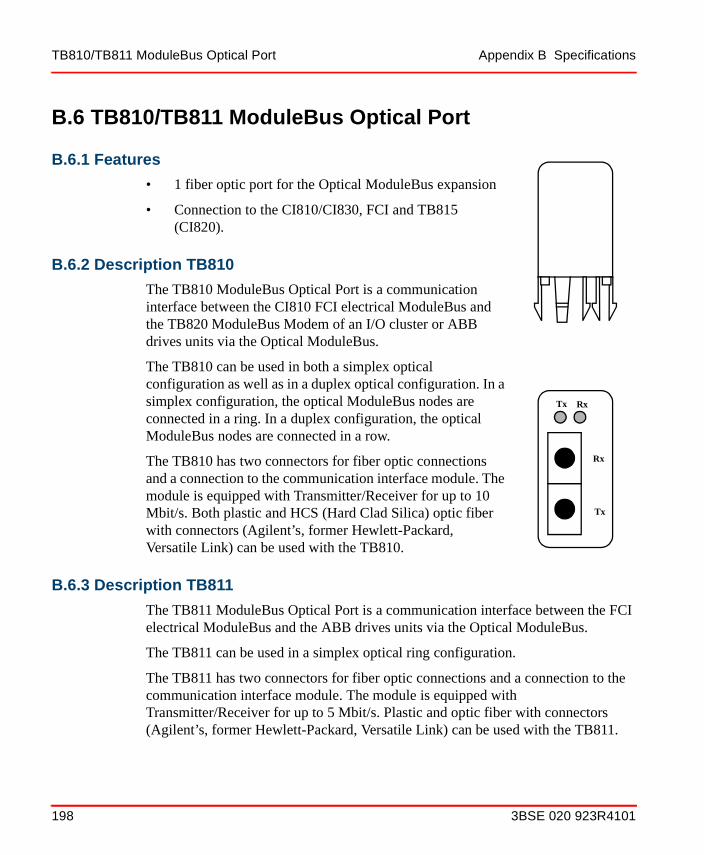
TB810/TB811 ModuleBus Optical Port Appendix B Specifications
B.6 TB810/TB811 ModuleBus Optical Port
B.6.1 Features
• 1 fiber optic port for the Optical ModuleBus expansion
• Connection to the CI810/CI830, FCI and TB815 (CI820).
B.6.2 Description TB810
The TB810 ModuleBus Optical Port is a communication interface between the CI810 FCI electrical ModuleBus and the TB820 ModuleBus Modem of an I/O cluster or ABB drives units via the Optical ModuleBus.
The TB810 can be used in both a simplex optical configuration as well as in a duplex optical configuration. In a simplex configuration, the optical ModuleBus nodes are connected in a ring. In a duplex configuration, the optical ModuleBus nodes are connected in a row.
The TB810 has two connectors for fiber optic connections and a connection to the communication interface module. The module is equipped with Transmitter/Receiver for up to 10 Mbit/s. Both plastic and HCS (Hard Clad Silica) optic fiber with connectors (Agilent’s, former Hewlett-Packard, Versatile Link) can be used with the TB810.
B.6.3 Description TB811
The TB811 ModuleBus Optical Port is a communication interface between the FCI electrical ModuleBus and the ABB drives units via the Optical ModuleBus.
The TB811 can be used in a simplex optical ring configuration.
The TB811 has two connectors for fiber optic connections and a connection to the communication interface module. The module is equipped with Transmitter/Receiver for up to 5 Mbit/s. Plastic and optic fiber with connectors (Agilent’s, former Hewlett-Packard, Versatile Link) can be used with the TB811.
Rx
Tx
Tx Rx
198 3BSE 020 923R4101

Appendix B Specifications TB810/TB811 ModuleBus Optical Port
B.6.4 Technical Data
Table B-10 TB810 ModuleBus Optical Port Specifications
Item TB810 TB811
Application S800 I/O clusters and ABB variable drives
ABB variable drives
Configuration Simplex and duplex Simplex
Fibers Plastic and HCS (Hard Clad Silica)
Plastic
Connector Agilent’s, former Hewlett-Packard, Versatile Link
Agilent’s, former Hewlett-Packard, Versatile Link
Optical ModuleBus Fiber optic interface, one transmit and one receive connection for max. 10 Mbit/s.
Wavelength 650 nm
Fiber optic interface, one transmit and one receive connection for max. 5 Mbit/s.
Wavelength 650 nm
Indicators Tx LED: Yellow indicates transmitting of data on the optical ModuleBus
Rx LED: Yellow indicates receiving of data on the optical ModuleBus
Tx LED: Yellow indicates transmitting of data on the optical ModuleBus
Rx LED: Yellow indicates receiving of data on the optical ModuleBus
Current consumption +5 V 100 mA 100 mA
Current consumption +24 V 20 mA 20 mA
Power dissipation 0.5 W 0.5 W
Equipment Class Class I according to IEC 60536; (earth protected)
Class I according to IEC 60536; (earth protected)
Ingress Protection IP20 according to IEC 60529 IP20 according to IEC 60529
Rated insulation voltage 50 V 50 V
Dielectric test voltage 500 V a.c. 500 V a.c.
Width 20 mm (0.79”) 20 mm (0.79”)
3BSE 020 923R4101 199

TB810/TB811 ModuleBus Optical Port Appendix B Specifications
B.6.5 Connections
B.6.6 Opto Cable for TB810 according to HP
Plastic Optical Fiber (POF) up to 15 meters.
• Extra low loss attenuation
• Simplex or duplex cable
• Latching simplex or duplex connector.
• Cable attenuation maximum 4 dB
Hard Clad Silica (HCS) fiber up to 200 meters.
• Riser or plenum
• Simplex or duplex cable
• Latching simplex or duplex connector
• Cable attenuation maximum 2 dB
Depth 39.6 mm (1.6”) 39.6 mm (1.6”)
Height 39.6 mm (1.6”) 39.6 mm (1.6”)
Weight 19 g (0.042 lbs.) 19 g (0.042 lbs.)
Table B-11 Optical ModuleBus Connections (X2)
Port Duplex Signals Simplex Signals
Tx Transmit data to down-stream device
Transmit data to next device
Rx Receive data from up-stream device
Receive data from last device
Table B-10 TB810 ModuleBus Optical Port Specifications (Continued)
Item TB810 TB811
200 3BSE 020 923R4101
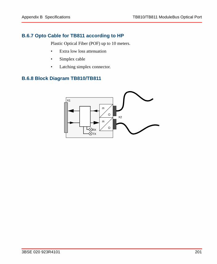
Appendix B Specifications TB810/TB811 ModuleBus Optical Port
B.6.7 Opto Cable for TB811 according to HP
Plastic Optical Fiber (POF) up to 10 meters.
• Extra low loss attenuation
• Simplex cable
• Latching simplex connector.
B.6.8 Block Diagram TB810/TB811
TXRX
X1
X2E
O
E
O
3BSE 020 923R4101 201

TB820 ModuleBus Modem Appendix B Specifications
B.7 TB820 ModuleBus Modem
B.7.1 Features
• 2 fiber optic ports to optical ModuleBus
• ModuleBus (electrical) to the I/O Modules
• Supervisory functions of I/O ModuleBus and power supply
• Isolated power supply to I/O modules
• DIN rail mounting.
B.7.2 Description
The TB820 ModuleBus Modem is a communication interface for connection of S800 I/O modules via the optical and electrical ModuleBus.
The module can not handle High Integrity I/O modules (AI880, DI880 and DO880).
The TB820 can be used in both a simplex optical configuration as well as in a duplex optical configuration. In a simplex configuration, the optical ModuleBus nodes are connected in a ring. In a duplex configuration, the optical ModuleBus nodes are connected in a row.
TB820 has two basic parts: Module termination board and the power supply/communications board (see block diagram).
The termination board is a unit where most of the connections to the outside takes place. It is grounded to the DIN rail through a metallic spring connector. The board carries screw terminals for power supply and redundant power supply monitoring, connector for the electrical ModuleBus, a current limit “fuse” for the +24 V supply of the I/O modules and the electrical ModuleBus.
12
75
34 6
CLUSTER
F R
Rx2Rx1P
TB820 V2
ERx
X4 X5Rx2
Tx2Rx1
Tx1SBSA
L+L-
202 3BSE 020 923R4101

Appendix B Specifications TB820 ModuleBus Modem
The power supply board has an isolated power converter that generates a short circuit proof +5 V supply for the TB820 and connected I/O modules. This board also contains the ModuleBus interfaces, LED indicators and one screwdriver maneuvered rotary switch for the ModuleBus I/O cluster address. The ModuleBus I/O cluster address (1-7) is set by a rotary decimal code switch, any other value than 1-7 is not allowed and will turn the Run LED off.
The ModuleBus has an electrical and an optical interface which are logically the same bus. A maximum of twelve I/O modules can be connected to the electrical ModuleBus and up to seven clusters can be connected to the fiber optic ModuleBus expansion. The fiber-optical interface is intended for local distribution of I/O clusters and where more than 12 I/O modules per station are required. Any distribution of I/O modules across the base cluster and the remote cluster(s) is allowed, however not more than 24 I/O modules per station can be used.
The module is equipped with optical Transmitter/Receiver for up to 10 Mbit/s. Both plastic and HCS (Hard Clad Silica) optic fiber with connectors (Agilent’s, former Hewlett-Packard, Versatile Link) can be used with TB820.
3BSE 020 923R4101 203

TB820 ModuleBus Modem Appendix B Specifications
B.7.3 Technical Data
Table B-12 TB820 ModuleBus Modem Specifications
Item Value
Power input 24 V d.c. (19.2 - 30)
Power consumption at 24V d.c. 100 mA
Power dissipation 6.0 W
Power supply monitoring inputs Max. input voltage: 30VMin. input voltage for high level: 15 VMax. input voltage for low level: 8 V
Power output (ModuleBus) 24 V max. = 1.4 A
5 V max. = 1.5 A
Electrical ModuleBus Maximum of 12 I/O modules
Optical ModuleBus
Fiber optic interface, two transmitters and two receivers for
Maximum of 7 I/O clusters
Max. 10 Mbit/s
Wavelength 650 nm
Maximum ambient temperature 55oC/(131°F)
204 3BSE 020 923R4101

Appendix B Specifications TB820 ModuleBus Modem
Indicators R(un) LED: Green indicates that the TB820 is operational
F(ault) LED: Red indicates a fault condition; Reset and communications errors on the electrical ModuleBus turns the LED on.
P(owok) LED: Green indicates that the d.c./d.c. converter generates a valid +5 V d.c.
ORx1 and ORx2 traffic LEDs: Yellow (blinking) indicates that the TB820 is receiving data on the two optical ModuleBus channels respectively.
ERx traffic LED: Yellow (blinking) indicates the TB820 is receiving data on the electrical ModuleBus.
Equipment Class Class I according to IEC 60536; (earth protected)
Ingress Protection IP20 according to IEC 60529
Rated insulation voltage 50 V
Dielectric test voltage 500 V a.c.
Width 58 mm (2.39”)
Depth 122 mm (4.8”)
Height 170 mm (6.7”) including latch
Weight 0.3 kg (0.66 lbs.)
Table B-12 TB820 ModuleBus Modem Specifications (Continued)
Item Value
3BSE 020 923R4101 205

TB820 ModuleBus Modem Appendix B Specifications
Figure B-12 TB820 Module
CLUSTER
BSA
L-L+ +
-
F R
ORx2ORx1
P
TB820
12
75
34 6
ERx
170
mm
(6.
7”)
58 mm (2.3”) 122 mm (4.8”)
SB
LL+SA
206 3BSE 020 923R4101

Appendix B Specifications TB820 ModuleBus Modem
B.7.4 Connections
Table B-13 Power Supply Connections TB820/TB820V1
Designation Description
L+ +24 V d.c. Supply In
L+ +24 V d.c. Supply Out
SA Redundant Power Supply “A” Monitoring Input
L- 0 V d.c. Supply In
L- 0 V d.c. Supply Out
SB Redundant Power Supply “B” Monitoring Input
Table B-14 Power Supply Connections TB820V2
Designation Description
L+ +24 V d.c. Supply
L- 0 V d.c. Supply
SA Redundant Power Supply “A” Monitoring Input
SB Redundant Power Supply “B” Monitoring Input
3BSE 020 923R4101 207

TB820 ModuleBus Modem Appendix B Specifications
Opto connectors type Agilent’s, former Hewlett-Packard, Versatile Link can handle both plastic and HCS optic fiber.
B.7.5 Opto Cable according to HP
Plastic Optical Fiber (POF) up to 15 meters.
• Extra low loss attenuation
• Simplex or duplex cable
• Latching simplex or duplex connector.
• Cable attenuation maximum 4 dB
Hard Clad Silica (HCS) fiber up to 200 meters.
• Riser or plenum
• Simplex or duplex cable
• Latching simplex or duplex connector
• Cable attenuation maximum 2 dB
Table B-15 Optical ModuleBus Connections (X4, X5)
Port Duplex Signals Simplex Signals
X4 - Tx Transmit data to down-stream device
Transmit data to next device
X4 - Rx Receive data from down-stream device
Not used
X5 - Tx Transmit data to up-stream device
Not used
X5 - Rx Receive data from up-stream device
Receive data from last device
208 3BSE 020 923R4101
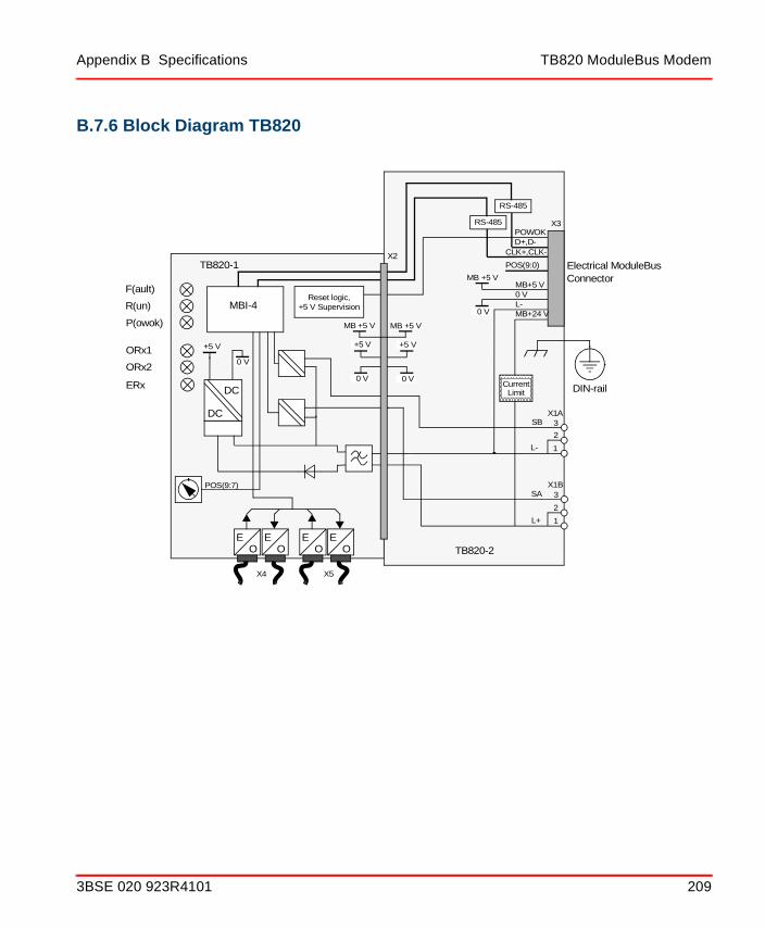
Appendix B Specifications TB820 ModuleBus Modem
B.7.6 Block Diagram TB820
DC
DC
POWOKD+,D-
POS(9:0)
MB+24 VL-0 VMB+5 V
SB
SA
L-
L+
P(owok)
R(un)
F(ault)
ORx2
ORx1
X3
X1A
1
2
1
3
3
2
TB820-1
TB820-2
Electrical ModuleBusConnector
EO
DIN-rail
X1B
CLK+,CLK-
POS(9:7)
EO
EO
EO
X2
ERx
X4 X5
MBI-4Reset logic,
+5 V Supervision
+5 V
MB +5 V MB +5 V
+5 V
0 V 0 VCurrent
Limit
MB +5 V
0 V
0 V
+5 V
RS-485
RS-485
3BSE 020 923R4101 209

TB825 Optical Media Converter Appendix B Specifications
B.8 TB825 Optical Media Converter
B.8.1 Features
• Converts between plastic or HCS opto fiber and glass optical fiber
• DIN rail mounted
• S800L mechanics
B.8.2 Description
ModuleBus Optical media converter, converts between plastic opto fiber or HCS fiber with Versatile link connectors and glass optical fiber with ST connectors.
210 3BSE 020 923R4101

Appendix B Specifications Technical Data
B.8.3 Technical Data
Table B-16 TB825 Optical Media Converter Specifications
Item Value
Power input 24 V (19.2 - 30)
Power consumption at 24V d.c. 96 mA
Power input fuse 2 A
Power dissipation 2.3 W
Optical ModuleBus
Fiber optic interface, three transmitters and three receivers for
Local Optical ModuleBus 1, 2 and Field Optical ModuleBus
Indicators (S) Status LED: Red indicates module fault. Green indicates Module OK (FPGA configuration).
Rx1 LED: Yellow indicates data received on opto port 1.
Tx1 LED: Yellow indicates data transmitted on opto port 1.
Rx2 LED: Yellow indicates data received on opto port 2.
Tx2 LED: Yellow indicates data transmitted on opto port 2.
Rx3 LED: Yellow indicates data received on opto port 3.
Tx3 LED: Yellow indicates data transmitted on opto port 3.
Equipment Class Class I according to IEC 60536; (earth protected)
Ingress Protection IP20 according to IEC 60529
Rated insulation voltage 50 V
3BSE 020 923R4101 211

Technical Data Appendix B Specifications
Dielectric test voltage 500 V a.c.
Width 86.1 mm (3.4”)
Depth 58.5 mm (2.3”)
Height 136 mm (4.33”) including latch
Weight 0.21 kg (0.46 lbs.)
Table B-16 TB825 Optical Media Converter Specifications (Continued)
Item Value
212 3BSE 020 923R4101

Appendix B Specifications Opto Connection
B.8.4 Opto Connection
B.8.4.1 Local Optical Cable
Opto connectors type Agilent’s, former Hewlett-Packard, Versatile Link can handle both plastic and HCS optic fibre.
Plastic Optical Fiber (POF) up to 15 meters.
• Extra low loss attenuation
• Simplex or duplex cable
• Latching simplex or duplex connector.
• Cable attenuation maximum 4 dB
Hard Clad Silica (HCS) fiber up to 200 meters.
• Riser or plenum
• Simplex or duplex cable
• Latching simplex or duplex connector
• Cable attenuation maximum 2 dB
B.8.4.2 Field Optical Cable
Glass Optical Fiber, multimode
• Fiber dimensions: 62.5/125 µm
• Connector type: ST, bayonet
• Wave length: 820 nm
• Max cable attenuation: 3.5 dB (1000 m of unspliced cable)
3BSE 020 923R4101 213
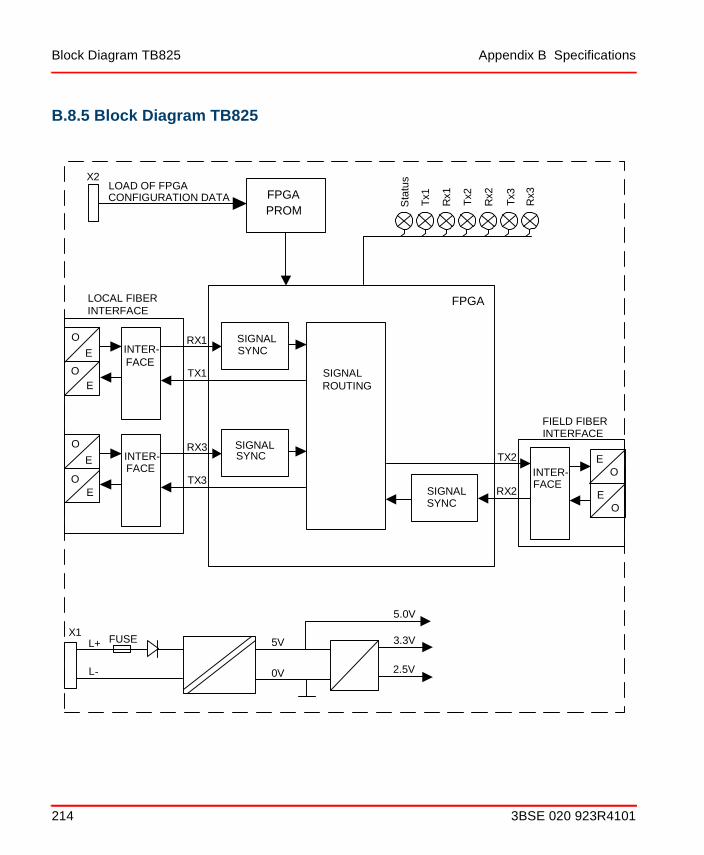
Block Diagram TB825 Appendix B Specifications
B.8.5 Block Diagram TB825
SIGNALSYNC
SIGNALROUTING
INTER-FACE
SIGNALSYNCINTER-
FACE
FPGA
X2
L+
L-
5V
0V
3.3V
2.5V
5.0V
FPGAPROM
LOAD OF FPGACONFIGURATION DATA
X1
RX1
TX1
RX3
TX3
LOCAL FIBERINTERFACE
Rx3
Tx3
Rx2
Tx2
Rx1
Tx1
Sta
tus
O
E
EO
O
E
EO
SIGNALSYNC
INTER-FACE
TX2
RX2
FIELD FIBERINTERFACE
OE
EO
FUSE
214 3BSE 020 923R4101

Appendix B Specifications TB840/TB840A ModuleBus Modem
B.9 TB840/TB840A ModuleBus Modem
B.9.1 Features
• 2 fiber optic ports to optical ModuleBus
• ModuleBus (electrical) to the I/O Modules
• Supervisory functions of I/O ModuleBus and power supply
• Isolated power supply to I/O modules
• Input power fused
B.9.2 Description
The TB840/TB840A ModuleBus Modem is a communication interface for connection of S800 I/O modules via the optical and electrical ModuleBus.
TB840/TB840A is designed to be used in 1+1 redundant applications.
TB840/TB840A can be used in both a simplex optical configuration as well as in a duplex optical configuration. In a simplex configuration, the optical ModuleBus nodes are connected in a ring. In a duplex configuration, the optical ModuleBus nodes are connected in a daisy-chain.
TB840/TB840A must be mounted on a Module Termination Unit TU841.
TU841 carries screw terminals for power supply and redundant power supply monitoring, connector for the electrical ModuleBus and a rotary switch for setting of the cluster address.
TB840/TB840A has isolated power converters that generates internal power for TB840/TB840A and short circuit proof +5 V supply for two electrical
TB840
S
Rx1Rx2
ERx1ERx2
P
3BSE 020 923R4101 215

TB840/TB840A ModuleBus Modem Appendix B Specifications
ModuleBuses. It also contains two ModuleBus interfaces and LED indicators. The ModuleBus I/O cluster address (1-7) is set by a rotary decimal code switch, on the Module Terminal Unit TU841.
TB840/TB840A has two electrical and one Optical ModuleBus Interface which are logically the same bus. Only one electrical ModuleBus is connected if TB840/TB840A is mounted on TU841. A maximum of twelve I/O modules can be connected to the electrical ModuleBus and up to seven clusters can be connected to the fiber optic ModuleBus expansion. The fiber-optical interface is intended for local distribution of I/O clusters and where more than 12 I/O modules per station are required. Any distribution of I/O modules across the base cluster and the remote cluster(s) is allowed, however not more than 24 I/O modules per I/O station can be used.
Both plastic and HCS (Hard Clad Silica) optic fiber with connectors (Agilent’s, former Hewlett-Packard, Versatile Link) can be used with TB840/TB840A.
216 3BSE 020 923R4101

Appendix B Specifications TB840/TB840A ModuleBus Modem
B.9.3 Technical Data
Table B-17 TB840/TB840A ModuleBus Modem Specifications
Item Value
Power input 24 V d.c. (19.2 - 30)
Power consumption at 24V d.c. 120 mA
Power input fuse 2 AF
Power dissipation 6 W
Power supply monitoring inputs Max. input voltage: 30VMin. input voltage for high level: 15 VMax. input voltage for low level: 8 V
Power output (ModuleBus) 24 V max. = 1.4 A
5 V max. = 1.5 A
Electrical ModuleBus Maximum of 12 I/O modules
Optical ModuleBus
Fiber optic interface, two transmitters and two receivers for
Maximum of 7 I/O clusters
Max. 10 Mbit/s
Wavelength 650 nm
3BSE 020 923R4101 217

TB840/TB840A ModuleBus Modem Appendix B Specifications
Indicators S(tatus) LED: Green indicates that the TB840 is operational.
Red indicates a fault condition; Reset and communications errors on the electrical ModuleBus turns the LED on.
P(owok) LED: Green indicates that the d.c./d.c. converter generates valid internal power and +5 V d.c. on the electrical ModuleBus.
Rx1 and Rx2 traffic LEDs: Yellow (blinking) indicates that the TB840 is receiving data on the two optical ModuleBus channels respectively.
ERx1 traffic LED: Yellow (blinking) indicates the TB840 is receiving data on the electrical ModuleBus A.
ERx2 traffic LED: Yellow blinking, indicates that the TB840 is receiving data on the electrical ModuleBus B.
MTU Keying code AB
Equipment Class Class I according to IEC 60536; (earth protected)
Ingress Protection IP20 according to IEC 60529
Rated insulation voltage 50 V
Dielectric test voltage 500 V a.c.
Width 54 mm (2.13”)
Depth 96 mm (3.78”)
Height 119 mm (4.69”) including latch
Weight 0.2 kg (0.44 lbs.)
Table B-17 TB840/TB840A ModuleBus Modem Specifications (Continued)
Item Value
218 3BSE 020 923R4101

Appendix B Specifications TB840/TB840A ModuleBus Modem
B.9.4 Connections
Opto connectors type Agilent’s, former Hewlett-Packard, Versatile Link can handle both plastic and HCS optic fiber.
B.9.5 Opto Cable according to HP
Plastic Optical Fiber (POF) up to 15 meters.
• Extra low loss attenuation
• Simplex or duplex cable
• Latching simplex or duplex connector.
Figure B-13 TB840/TB840A Module
119 mm(4.69”)
54 mm (2.13”)
96 mm(3.78”)
X4
X5
3BSE 020 923R4101 219

TB840/TB840A ModuleBus Modem Appendix B Specifications
• Cable attenuation maximum 4 dB
Hard Clad Silica (HCS) fiber up to 200 meters.
• Riser or plenum
• Simplex or duplex cable
• Latching simplex or duplex connector
• Cable attenuation maximum 2 dB
Table B-18 Power Supply Connections
Designation Description
L+ +24 V d.c. Supply
L- 0 V d.c. Supply
SA Redundant Power Supply “A” Monitoring Input
SB Redundant Power Supply “B” Monitoring Input
Table B-19 Optical ModuleBus Connections (X4, X5)
Port Duplex Signals Simplex Signals
X4 - Tx Transmit data to down-stream device
Transmit data to next device
X4 - Rx Receive data from down-stream device
Not used
X5 - Tx Transmit data to up-stream device
Not used
X5 - Rx Receive data from up-stream device
Receive data from last device
220 3BSE 020 923R4101

Appendix B Specifications TB840/TB840A ModuleBus Modem
B.9.6 Connection Diagram TB840/TB840AT
U84
1
TB
840/
TB
840A
TB
840/
TB
840A
Ter
min
atio
n U
nit f
or R
edun
dant
TB
840/
TB
840A
Mod
uleB
us O
ptic
al M
odem
Mod
uleB
us O
ptic
al M
odem
EE EE EE EE
CLU
ST
ER
AD
DR
ES
S1
0987
65
4 3 2
S(T
AT
US
)
P(O
WE
R)
Rx1
Rx2
ER
x1
ER
x2
S(T
AT
US
)
P(O
WE
R)
Rx1
Rx2
ER
x1
ER
x2
KE
Y C
OD
E:A
B
KE
Y C
OD
E:A
B
Mod
uleB
us
Rx1
= R
ecei
ve fr
om u
pstr
eam
Rx2
= R
ecei
ve fr
om d
owns
trea
m (
dupl
ex o
nly)
ER
x1=
Rec
eive
from
ele
ctric
al M
odul
eBus
AE
Rx2
= R
ecei
ve fr
om e
lect
rical
Mod
uleB
us B
Rx1
= R
ecei
ve fr
om u
pstr
eam
Rx2
= R
ecei
ve fr
om d
owns
trea
m (
dupl
ex o
nly)
ER
x1=
Rec
eive
from
ele
ctric
al M
odul
eBus
AE
Rx2
= R
ecei
ve fr
om e
lect
rical
Mod
uleB
us B
Tx2
Rx2
Tx1
Rx1
Tx2
Rx2
Tx1
Rx1
4 3 2 1
L+ L- SA
SB
x4 x5 x4 x5
10
9876
54 3 2
3BSE 020 923R4101 221

TB842 ModuleBus Optical Port Appendix B Specifications
B.10 TB842 ModuleBus Optical Port
B.10.1 Features
• 1 fiber optic port for the Optical ModuleBus expansion
• Connection to CI801 and CI840
B.10.2 Description TB842
TB842 ModuleBus Optical Port is a communication interface between the CI801 or CI840 FCI and the TB820 ModuleBus Modem of an I/O cluster or ABB drives units via the Optical ModuleBus.
TB842 connects to CI801 via TB806 or CI840 via TU847 and TB806.
TB842 can be used in both a simplex optical configuration as well as in a duplex optical configuration. In a simplex configuration, the optical ModuleBus nodes are connected in a ring. In a duplex configuration, the optical ModuleBus nodes are connected in a row.
TB842 has two connectors for fiber optic connections and a connection to the communication interface module. The module is equipped with Transmitter/Receiver for up to 10 Mbit/s. Both plastic and HCS (Hard Clad Silica) optic fiber with connectors (Agilent’s, former Hewlett-Packard, Versatile Link) can be used with the TB842.
222 3BSE 020 923R4101
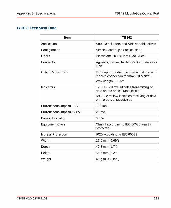
Appendix B Specifications TB842 ModuleBus Optical Port
B.10.3 Technical Data
Item TB842
Application S800 I/O clusters and ABB variable drives
Configuration Simplex and duplex optical fiber
Fibers Plastic and HCS (Hard Clad Silica)
Connector Agilent’s, former Hewlett-Packard, Versatile Link
Optical ModuleBus Fiber optic interface, one transmit and one receive connection for max. 10 Mbit/s.
Wavelength 650 nm
Indicators Tx LED: Yellow indicates transmitting of data on the optical ModuleBus
Rx LED: Yellow indicates receiving of data on the optical ModuleBus
Current consumption +5 V 100 mA
Current consumption +24 V 20 mA
Power dissipation 0.5 W
Equipment Class Class I according to IEC 60536; (earth protected)
Ingress Protection IP20 according to IEC 60529
Width 17.6 mm (0.69”)
Depth 42.3 mm (1.7”)
Height 56.7 mm (2.2”)
Weight 40 g (0.088 lbs.)
3BSE 020 923R4101 223

TB842 ModuleBus Optical Port Appendix B Specifications
B.10.4 Connections
B.10.5 Opto Cable for TB842 according to HP
Plastic Optical Fiber (POF) up to 15 meters.
• Extra low loss attenuation
• Simplex or duplex cable
• Latching simplex or duplex connector.
• Cable attenuation maximum 4 dB
Hard Clad Silica (HCS) fiber up to 200 meters.
• Riser or plenum
• Simplex or duplex cable
• Latching simplex or duplex connector
• Cable attenuation maximum 2 dB
Table B-20 Optical ModuleBus Connections (X2)
Port Duplex Signals Simplex Signals
Tx Transmit data to down-stream device
Transmit data to first device
Rx Receive data from up-stream device
Receive data from last device
224 3BSE 020 923R4101

Appendix B Specifications TB842 ModuleBus Optical Port
B.10.6 Block Diagram TB842
TXRX
X1
X2
E
O
E
O
3BSE 020 923R4101 225

TB845/TB846 ModuleBus Cable Adapter-Out/In Appendix B Specifications
B.11 TB845/TB846 ModuleBus Cable Adapter-Out/In
B.11.1 Features
• Passive unit used for connection and extension of the ModuleBus
• DIN rail mounting.
B.11.2 Description
The TB845 ModuleBus Cable Adaptor-Out and TB846 ModuleBus Cable Adaptor-In with the ModuleBus Extension Cables, TK801V0xx, are used to extend the ModuleBus.
Using the TB845 and TB846, I/O modules on the same electrical ModuleBus of an I/O cluster, can be mounted on different DIN rails. This makes the installation of I/O Modules more flexible when laying out an enclosure design. Please refer to Section 2, Installation for details on layouts.
The ModuleBus extension cables used with the TB845/TB846 comes in 3 standard lengths:
• VTK801V003 - 300 mm
• TK801V006 - 600 mm
• TK801V012 - 1.2 meters.
Overall ModuleBus length must not exceed 2.5 meters including all cables and MTUs.
TB846 is also used for connection of the optical port TB842 to TU846 (CI840).
DB25 FemaleConnector (X2B)
TB845 ModuleBusConnector (X1A)
TB845 ModuleBusConnector (X1B)
DB25 FemaleConnector (X2A)
DB25 MaleConnector (X2B)
DB25 MaleConnector (X2A)
TB846 ModuleBusConnector (X1A)
TB846 ModuleBusConnector (X1B)
226 3BSE 020 923R4101

Appendix B Specifications TB845/TB846 ModuleBus Cable Adapter-Out/In
The TB845/TB846 mounts on the standard DIN rail. It has a mechanical latch that locks it to the rail. It is grounded to the DIN-rail through a metallic spring connector. The latch can be released with a screwdriver.
3BSE 020 923R4101 227

TB845/TB846 ModuleBus Cable Adapter-Out/In Appendix B Specifications
B.11.3 Technical Data
Table B-21 TB845/TB846 ModuleBus Cable Adaptor Specifications
Item TB845 TB846
Direction Out In
Connections 42 DIN41612 Type R/4 (X1)2 DB25 Female (X2)
42 DIN41612 Type R/4 (X1)2 DB25 Male (X2)
ModuleBus:Maximum 5 V current distributionMaximum 24 V current distribution
1.5 A1.5 A
1.5 A1.5 A
Module catch Locks module to previous device
Locks module to previous device
Module DIN rail lock Locks module and provide ground connection
Locks module and provide ground connection
Equipment Class Class I according to IEC 60536; (earth protected)
Class I according to IEC 60536; (earth protected)
Ingress Protection IP20 according to IEC 60529 IP20 according to IEC 60529
Rated Insulation Voltage 50 V 50 V
Dielectric test voltage 500 V a.c. 500 V a.c.
Width 49.8 mm (1.96”) incl. connectors 43 mm (1.69”)
Depth 31.5 mm (0.98”) 31.5 mm (1.24”)
Height 186 mm (7.32”) incl. latch 186 mm (7.32”) incl. latch
Weight 180 g (0.4 lbs.) 180 g (0.4 lbs.)
228 3BSE 020 923R4101

Appendix B Specifications TB845/TB846 ModuleBus Cable Adapter-Out/In
B.11.4 Block Diagram TB845
B.11.5 Block Diagram TB846
X2POS 0 - 6 /
7
POWOK
DAT, DAT-N/
2
+24 V, 0 V24/
2
+5 V/
5
0 V/
4
EM
Shield
CLK+, CLK-/
2
X1
ModuleB
us Connector R
/4 Fem
ale
ModuleB
us Connector D
B25 F
emale
X2
POS 0 - 6/7
POWOK
DAT, DAT-N/2
+24 V, 0 V24/2
+5 V/5
0 V/4
EM
Shield
CLK+, CLK-/
2
X1
ModuleB
us Connector R
/4 Male
ModuleB
us Connector D
B25 M
ale
3BSE 020 923R4101 229

TU840, MTU for Redundant TB840/TB840A with Dual ModuleBus Appendix B Specifications
B.12 TU840, MTU for Redundant TB840/TB840A with Dual ModuleBus
B.12.1 Features
• Power supply connection
• A rotary switch for cluster address setting
• Mechanical keying prevents insertion of wrong module type
• Double ModuleBus connection
• Latching device to DIN rail for locking and grounding
• DIN rail mounted.
B.12.2 Description
The TU840 is a module termination unit (MTU) for redundant configuration of Optical ModuleBus Modem TB840.
The MTU is a passive unit having connections for power supply, double electrical ModuleBus, two TB840/TB840A and a rotary switch for cluster address (1 to 7) setting.
Four mechanical keys, two for each position, are used to configured the MTU for the right types of modules. Each key has six positions, which gives a total number of 36 different configurations. The configurations can be changed with a screwdriver.
The MTU can be mounted on a standard DIN rail. It has a mechanical latch that locks the MTU to the DIN rail. The latch can be locked/unlocked with a screwdriver.
The MTU has two BLOCK signals, one for each module position, that keeps the modules in its INIT state until it is locked in its position.
CLUSTER ADDR.
230 3BSE 020 923R4101

Appendix B Specifications TU840, MTU for Redundant TB840/TB840A with Dual ModuleBus
B.12.3 Technical Data
Table B-22 TU840 Redundant MTU for TB840/TB840A
Item Value
Power input 24 V d.c. (19.2 - 30 V)
ModuleBus current distributionMaximum 5 V24 V
1.5 A1.5 A
Mechanical keys (2) 36 different combinations
Equipment Class Class I according to IEC 60536; (earth protected)
Ingress Protection IP20 according to IEC 60529
Rated insulation voltage 50 V
Dielectric test voltage 500 V a.c.
Width 124 mm (4.88”)
Depth 47 mm (1.85”)
Height 186 mm (7.32”) including latch
Weight 0.45 kg (0.99 lbs.)
3BSE 020 923R4101 231

TU840, MTU for Redundant TB840/TB840A with Dual ModuleBus Appendix B Specifications
B.12.4 Dimensions
Figure B-14 Dimensions TU840
124 mm (4.88”)
5mm(0.2”)
90 mm (3.54”)
47 mm (1.85”)
39 mm (1.54”)
162.9 mm(6.41”)
186.9 mm(7.36”)
Center ofDIN rail
99.5 mm(3.92”)
CLUSTER ADDR.
17 mm(0.67”)
232 3BSE 020 923R4101

Appendix B Specifications TU840, MTU for Redundant TB840/TB840A with Dual ModuleBus
B.12.5 Connections
Table B-23 TU840 Power Supply Connections
Designation Description
L+ +24 V d.c. Supply In
L- 0 V d.c. Supply In
SA Redundant Power Supply “A” Monitoring Input
SB Redundant Power Supply “B” Monitoring Input
3BSE 020 923R4101 233
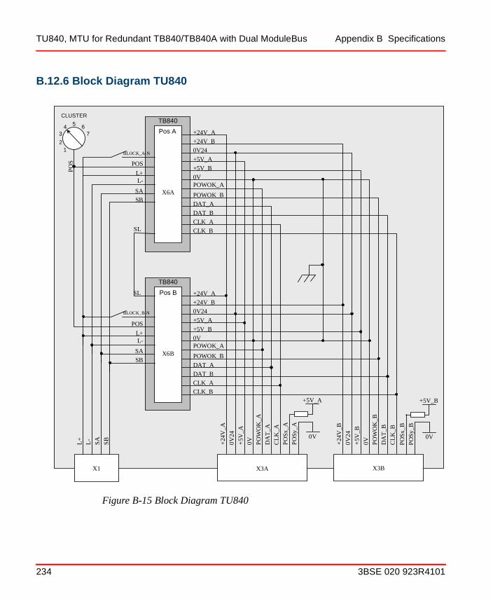
TU840, MTU for Redundant TB840/TB840A with Dual ModuleBus Appendix B Specifications
B.12.6 Block Diagram TU840
Figure B-15 Block Diagram TU840
X6B
TB840B
POWOK_A
+24
V_A
POWOK_B
DAT_A
+5V_A
+5V_B
0V
+24V_B
+24V_A
0V24
DAT_B
CLK_A
CLK_B
POWOK_A
POWOK_B
DAT_A
+5V_A
+5V_B
0V
+24V_B
+24V_A
0V24
DAT_B
CLK_A CLK_B
0V24
+5V
_A
0V
PO
WO
K_A
DA
T_A
CL
K_A
+24
V_B
0V24
+5V
_B
0V
PO
WO
K_B
DA
T_B
CL
K_B
X6A
TB840A
X3A X3B X1
L-
SA
SB
L+
POS
L-
SASB
L+
POS
L+
L-
SA
SB
PO
S
CLUSTER
1 2
3 4 5 6
7
PO
Sx_A
PO
Sy_A
+5V_A
0V
PO
Sx_
B
PO
Sy_
B
+5V_B
0V
SL
SL
BLOCK_B-N
BLOCK_A-N
TB840
TB840
Pos A
Pos B
234 3BSE 020 923R4101

Appendix B Specifications TU841, MTU for Redundant TB840/TB840A with Single ModuleBus
B.13 TU841, MTU for Redundant TB840/TB840A with Single ModuleBus
B.13.1 Features
• Power supply connection
• A rotary switch for cluster address setting
• Mechanical keying prevents insertion of wrong module type
• Single ModuleBus connection
• Latching device to DIN rail for locking and grounding
• DIN rail mounted.
B.13.2 Description
The TU841 is a module termination unit (MTU) for redundant configuration of Optical ModuleBus Modem TB840/TB840A.
The MTU is a passive unit having connections for power supply, a single electrical ModuleBus, two TB840/TB840A and a rotary switch for cluster address (1 to 7) setting.
Four mechanical keys, two for each position, are used to configured the MTU for the right types of modules. Each key has six positions, which gives a total number of 36 different configurations. The configurations can be changed with a screwdriver.
The MTU can be mounted on a standard DIN rail. It has a mechanical latch that locks the MTU to the DIN rail. The latch can be locked/unlocked with a screwdriver.
The MTU has two BLOCK signals, one for each module position, that keeps the modules in its INIT state until it is locked in its position.
CLUSTER ADDR.
3BSE 020 923R4101 235

TU841, MTU for Redundant TB840/TB840A with Single ModuleBus Appendix B Specifications
B.13.3 Technical Data
Table B-24 TU841 Redundant MTU for TB840/TB840A
Item Value
Power input 24 V d.c. (19.2 - 30 V)
ModuleBus current distributionMaximum 5 V24 V
1.5 A1.5 A
Mechanical keys (2) 36 different combinations
Equipment Class Class I according to IEC 60536; (earth protected)
Ingress Protection IP20 according to IEC 60529
Rated insulation voltage 50 V
Dielectric test voltage 500 V a.c.
Width 124 mm (4.88”)
Depth 47 mm (1.85”)
Height 186 mm (7.32”) including latch
Weight 0.45 kg (0.99 lbs.)
236 3BSE 020 923R4101

Appendix B Specifications TU841, MTU for Redundant TB840/TB840A with Single ModuleBus
B.13.4 Dimensions
Figure B-16 Dimensions TU841
124 mm (4.88”)
5mm(0.2”)
90 mm (3.54”)
47 mm (1.85”)
39 mm (1.54”)
162.9 mm(6.41”)
186.5 mm(7.34”)
Center ofDIN rail
99.5 mm(3.92”)
CLUSTER ADDR.
17 mm(0.67”)
3BSE 020 923R4101 237

TU841, MTU for Redundant TB840/TB840A with Single ModuleBus Appendix B Specifications
B.13.5 Connections
Table B-25 TU841 Power Supply Connections
Designation Description
L+ +24 V d.c. Supply In
L- 0 V d.c. Supply In
SA Redundant Power Supply “A” Monitoring Input
SB Redundant Power Supply “B” Monitoring Input
238 3BSE 020 923R4101

Appendix B Specifications TU841, MTU for Redundant TB840/TB840A with Single ModuleBus
B.13.6 Block Diagram TU841
Figure B-17 Block Diagram TU841
X6B
TB840B
POWOK_A
+24
V_A
DAT_A
+5V_A
0V
+24V_A
0V24
CLK_A
POWOK_A
DAT_A
+5V_A
0V
+24V_A
0V24
CLK_A
0V24
+5V
_A
0V
POW
OK
_A
DA
T_A
CL
K_A
X6A
TB840A
X3A X1
L-
SA
SB
L+
POS
L-
SA
SB
L+
POS
L+
L-
SA
SB
POS
CLUSTER
1 2
3 4 5 6
7
POSx
_A
POSy
_A
+5V_A
0V
SL
SL
BLOCK_B-N
BLOCK_A-N
TB840
Pos A
TB840
Pos B
3BSE 020 923R4101 239

TU841, MTU for Redundant TB840/TB840A with Single ModuleBus Appendix B Specifications
240 3BSE 020 923R4101

Appendix C Power Up
C.1 Power Up on S800 I/OS800 I/O will start under four different conditions.
1. Without configuration and without communication with the controller. Start the first time or after a long power off.
2. Without configuration but with communication with the controller. Start the first time or after a long power off.
3. With configuration but without communication with the controller. Start after a short power off.
4. With configuration and with communication with the controller. Start after a short power off.
Below follows a description how to start and how S800 behaves during start-up under different conditions.
1. Check that the circuit breakers on the power switch units are switched off.
2. Switch on the mains power, and check for correct mains voltage with a multimeter.
3. Switch on the circuit breaker on the power switch unit(s).
Without configuration and without communications with the controller: See timing diagram Figure C-1.
Indications on FCI
F (fault) “on” at power up and “off” after self-test okR (run) “off”P (pow ok) “on” if power supply okT1 “off”
3BSE 020 923R4101 241

Power Up on S800 I/O Appendix C Power Up
T2 “off”PR “on” (only primary FCI in a redundant configuration)DU “off” (both FCI in a redundant configuration).
Indications on I/O Modules
F (fault) “on”R (run) “off”W (warning) “off”O (osp only outputs) “off”
Without configuration but with communications with the controller: See timing diagram Figure C-2.
Indications on FCI
F (fault) “on” at power up and “off” after self-test okR (run) “off” at power up and “on” after configuration ok
and commanded operational from the controller(can take about 1 to 4 minutes)
P (pow ok) “on” if power supply okT1 “on” if cable 1 okT2 “on” if cable 2 okPR “on” (only primary FCI in a redundant configuration)DU “off” (both FCI in a redundant configuration)
The backup will be started up after the I/O. When the backup has started
PR “on” (only primary FCI in a redundant configuration)DU “on” (both FCI in a redundant configuration)
Indications on I/O Modules
F (fault “on” at power up and “off” after the first accessfrom the FCI
R (run) “off” at power up and “on” for AI, DI afterconfiguration and for AO, DO after configuration andcommanded operational from the controller
W (warning “off” at power up and after module operational updated from the module
O (outputs only) “off” at power up and after module operational updated from the module
242 3BSE 020 923R4101

Appendix C Power Up Power Up on S800 I/O
With configuration but without communications with the controller: See timing diagram Figure C-3.
Indications on FCI
F (fault) “on” at power up and “off” after self-test okR (run) “off”P (pow ok) “on” if power supply okT1 “off”T2 “off”PR “on” (only primary FCI in a redundant configuration)DU “off” (both FCI in a redundant configuration)
Indications on I/O Modules
F (fault) “on” at power up and “off” after the first access fromthe FCI
R (run) “off” at power up and “on” for AI, DI afterconfiguration from the FCI. AO and DOremains in “off”
W (warning) “off” at power up and after module operational updated from the module
O (osp only outputs) “off”
With configuration and communications with the controller: See timing diagram Figure C-4.
Indications on FCI
F (fault) “on” at power up and “off” after self-test okR (run) “off” at power up and “on” after configuration and
commanded operational from the controller.(can take about 1 to 4 minutes)
P (pow ok) “on” if power supply okT1 “on” if cable 1 okT2 “on” if cable 2 ok
The backup will be started up after the I/O. When the backup has started
PR “on” (only primary FCI in a redundant configuration)DU “on” (both FCI in a redundant configuration)
3BSE 020 923R4101 243

Power Up on S800 I/O Appendix C Power Up
Indications on I/O Modules
F (fault) “on” at power up and “off” after the first access fromthe FCI
R (run) “off” at power up and “on” for AI, DI afterconfiguration and for AO,DO after configuration andcommanded operational from the controller
W (warning) “off” at power up and after the module operational updated from the module
O (osp only outputs) “off” at power up and after module is operational it is handled by the module
Power up of backup FCI in a running system:See timing diagram Figure C-5.
Indications on FCI
PrimaryF (fault) “off” R (run) “on”P (pow ok) “on”T1 “on”T2 “on”PR “on” DU “off” (on when the backup is running)
BackupF (fault) “off” R (run) “off” (on when the backup is running)P (pow ok) “on”T1 “on”T2 “on”PR “off” DU “off” (on when the backup is running)
244 3BSE 020 923R4101

Appendix C Power Up Power Up on S800 I/O
Figure C-1 Power-up Timing Diagram, no Configuration and no Communications to Controller
F
R
P
F
W
R
FCI
I/O module
OSP
Power up INIT in FCIS800 I/O
DU (both)
PR (primary)
PR (backup)
T1/T2
3BSE 020 923R4101 245

Power Up on S800 I/O Appendix C Power Up
Figure C-2 Power-up Timing Diagram, no Configuration and Communications to Controller
F
R
P
F
R (AO, DO)
W, OSP (AO, DO)
T1
T2
FCI
I/O module
R (AI, DI)
W (AI, DI)
Power up INIT
FCI operational
Start of I/O
S800 I/O
PR (primary)
PR (backup)
DU (both)
R (backup)
backupINIT
in FCI
246 3BSE 020 923R4101

Appendix C Power Up Power Up on S800 I/O
Figure C-3 Power-up Timing Diagram, with Configuration and no Communications to Controller
F
R
P
T1/T2
F
R (AI, DI)
W (AI, DI)
R (AO, DO)
FCI
I/O module
W (AO, DO)
Power up INITStart of I/O
S800 I/O
DU (both)
PR (primary)
PR (backup)
in FCI
3BSE 020 923R4101 247

Power Up on S800 I/O Appendix C Power Up
Figure C-4 Power-up Timing Diagram, with Configuration and Communications to Controller
F
R
P
F
R (AO, DO)
W, OSP (AO, DO)
T1
T2
FCI
I/O module
R (AI, DI)
W (AI, DI)
Power up INIT
FCI operational
Start of I/O
S800 I/O
PR (primary)
PR (backup)
DU (both)
R (backup)
INITbackup
248 3BSE 020 923R4101
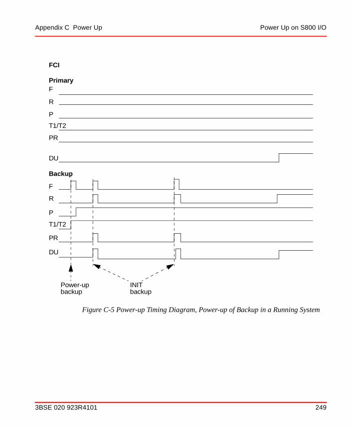
Appendix C Power Up Power Up on S800 I/O
Figure C-5 Power-up Timing Diagram, Power-up of Backup in a Running System
F
R
P
T1/T2
PR
DU
Backup
Primary
F
R
P
T1/T2
PR
DU
INIT backup
Power-upbackup
FCI
3BSE 020 923R4101 249

Power Up on S800 I/O Appendix C Power Up
250 3BSE 020 923R4101
INDEX
AA.C. supply 84Address setting 95Advant Fieldbus 100 94AI801 23AI810 23AI820 23AI825 23AI830 23AI835 23AI843 23AI845 23AI880 23AI890 24AI893 24AI895 24AO801 24AO810 24AO820 24AO845 24AO890 24AO895 24
CCable adaptor 27Cable considerations 81Check of non-redundant power supply 157Check of redundant power supply 158CI801 24CI810/CI810A/CI810B 24, 32CI820 24, 33CI830 24, 33, 94CI840 24Cooling load 145
DD.C. supply 84DI801 24DI802 25DI803 25DI810 25DI811 25DI814 25DI820 25DI821 25DI825 25DI830 25DI831 25DI840 25DI880 25DI885 25DI890 25DIN-rail 58Dissipation permitted in cabinets 142Distributed MTUs 95DO801 25DO802 26DO810 26DO814 26DO815 26DO820 26DO821 26DO840 26DO880 26DO890 26DP820 26DP840 26
3BSE 020 923R4101 251

Index
EEnvironmental considerations 56Extension cables 30
FFCI 17, 32 to 33
CI801 124CI810 124CI810A 124CI820 124CI830 124CI840 124
Fieldbus connection 94
GG3 compliant 17, 23Ground contact 61Grounding 79, 90
Process signals 91Protective ground 80Signals and voltage supply 80
HHardware configuration 113Hazardous applications 84Heat dissipation 142High voltage switch-gear applications 84
II/O clusters (1-7) 95I/O module installation 75I/O module replacement 158I/O modules 44I/O Station
Assembly 93I/O station 17, 58Industrial environments 81Installation
Checklists 97
LLED
Location 154LEDs 153Lightning strike protection 84
MMaximum ambient temperature 145Module termination units 44ModuleBus extension 28ModuleBus extension cable 68ModuleBus modem 161, 202, 215ModuleBus optical port 70
TB810 70ModuleBus terminator 77
OOptical ModuleBus expansion 70
PPersonnel safety 89Power
A.C. supply 84D.C. supply 84Requirements 83
Power and cooling 145Power consumption 144Power Dissipation 145Power supply 45
Load calculation 141Procedure
Power up 241Process signals 95PROFIBUS-DP 18, 24, 33PROFIBUS-DPV1 18, 24, 32, 34
RRedundant FCI installation 64
252 3BSE 020 923R4101
Index
SS800 I/O
Assembly 93Installation 56
Safety regulations 88SD821 26SD822 26SD823 26Shut down
Emergency 105Manual stop 106Safety 105
SS822 27SS823 27
TTB805 27TB806 27TB807 27, 77TB810 27, 70TB810/811 161TB811 27TB815 27TB820 27, 161TB825 27TB840 27TB842 27TB845 27TB846 27TC501V150 27TC505 27Temperature 57
Cabinetry factors 57I/O module factors 57
Terminator 27TK801V003 28TK801V006 28TK801V012 28TK811V015 28TK811V050 28
TK811V150 28TK812V015 28TK812V050 28TK812V150 28TU805 28TU810 28TU811 28TU814 28TU830 28TU831 28TU835 28TU836 28TU837 29TU838 29TU840 29TU841 29TU842 29TU843 29TU844 29TU845 29TU846 29TU847 29TU890 29TU891 29TY801 29TY804 29
VVentilation 142Vibration 58
3BSE 020 923R4101 253

Index
254 3BSE 020 923R4101


3BSE 020 923R4101. Printed in Sweden June 2005Copyright © 2005 by ABB. All Rights Reserved® Registered Trademark of ABB.™ Trademark of ABB.
Automation Technology ProductsMannheim, Germanywww.abb.de/processautomationemail: [email protected]
Automation Technology Products Västerås, Swedenwww.abb.com/processautomationemail: [email protected]
Automation Technology ProductsWickliffe, Ohio, USAwww.abb.com/processautomationemail: [email protected]
http://www.abb.com/control