industrial 800xa - device management hart€¦ · fieldbus topology in the 800xa system ... about...
TRANSCRIPT
IndustrialIT800xA - Device Management
HARTSystem Version 4.1
Configuration

Configuration
IndustrialIT800xA - Device Management
HARTSystem Version 4.1
NOTICEThe information in this document is subject to change without notice and should not beconstrued as a commitment by ABB. ABB assumes no responsibility for any errors thatmay appear in this document.
In no event shall ABB be liable for direct, indirect, special, incidental or consequentialdamages of any nature or kind arising from the use of this document, nor shall ABB beliable for incidental or consequential damages arising from use of any software or hard-ware described in this document.
This document and parts thereof must not be reproduced or copied without written per-mission from ABB, and the contents thereof must not be imparted to a third party nor usedfor any unauthorized purpose.
The software or hardware described in this document is furnished under a license andmay be used, copied, or disclosed only in accordance with the terms of such license.
Copyright © 2003-2005 by ABB. All rights reserved.
Release: May 2005Document number: 3BDD011748R4101
TRADEMARKSRegistrations and trademarks used in this document include:
Windows Registered trademark of Microsoft Corporation.
ActiveX Registered trademark of Microsoft Corporation.
PostScript Registered trademark of Adobe Systems Inc.
Acrobat Reader Registered trademark of Adobe Systems Inc.
xxxx IT All names in the form of xxxx IT (e.g. Industrial IT) are Trademarks of ABB.
TABLE OF CONTENTS
About This BookGeneral ............................................................................................................................11
Use of Caution, Information, and Tip Icons ....................................................................11
Document Conventions ...................................................................................................12
Terminology.....................................................................................................................13
Relevant Documentation .................................................................................................15
Section 1 - IntroductionProduct Overview ............................................................................................................17
Notes for use....................................................................................................................19
Components and Functions .............................................................................................21
Fieldbus Builder PROFIBUS/HART with OPC Server .......................................21
Fieldbus Builder PROFIBUS/HART ..................................................21
OPC Server PROFIBUS/HART..........................................................21
HART Device Integration Library .......................................................................23
Product Documentation.......................................................................23
Asset Monitoring.................................................................................23
Maintenance Management ..................................................................23
DMS Integration..................................................................................23
Device Type Manager .........................................................................24
Device Library Wizard and Device Object Types (optional) ..........................................25
HART Multiplexer Connect ............................................................................................25
New In This Release........................................................................................................26
Prerequisites and Requirements ......................................................................................27
Intended User...................................................................................................................27
Product Support ...............................................................................................................27
3BDD011748R4101 5

Table of Contents
Section 2 - Getting StartedOverview .........................................................................................................................29
Prerequisites and Requirements ...................................................................................... 29
Fieldbus topology in the 800xA system............................................................... 30
Preparing device object types for usage.......................................................................... 32
Installation of Device Type Manager (DTM) ......................................................33
System 800xA Server Path Settings .................................................................... 35
Pre-configuration of the OPC Server PROFIBUS/HART ................................... 38
Pre-commissioning Control Networks, AC 800M and OPC ..........................................41
Creating an AC 800M Controller......................................................................... 41
OPC Server assignment to a Connectivity Server ............................................... 43
OPC Server PROFIBUS/HART.......................................................... 44
AC 800M OPC Server ........................................................................47
Pre-configuration of the AC 800M controller......................................................48
Setting up a Fieldbus Topology for HART ..................................................................... 50
Local S800 modules on the AC 800M controller ................................................50
PROFIBUS Remote I/O and HART modules......................................................51
Pre-settings for Instantiation................................................................................ 53
Communication mode via Fieldbus Management aspect ...................53
Communication mode via Device Functions menu ............................ 55
Instancing of HART Device Objects ................................................................... 56
HART Device Objects below HART I/O modules ............................. 56
Channel allocation on I/O modules .................................................... 59
Configuration and commissioning of HART Device Objects ............................. 61
Verify ..................................................................................................61
Download and Upload ........................................................................62
Export and Import ............................................................................... 62
Synchronization of DTM specific data through the 800xA system....62
Channel Changes on I/O Modules .......................................................................63
Deleting Device Objects ...................................................................................... 64
6 3BDD011748R4101
Table of Contents
Starting the Device Type Manager (DTM)......................................................................65
Open DTM via Device Management Aspect .......................................................66
Open DTM via context menu in the Control Structure........................................67
Starting OPC Server PROFIBUS/HART.........................................................................68
Section 3 - Fieldbus Builder PROFIBUS/HARTOverview..........................................................................................................................71
FDT 1.2 User Roles in the 800xA System ......................................................................73
Fieldbus Builder PROFIBUS/HART Aspects .................................................................74
Aspect Overview ..................................................................................................74
Aspects in the Object Type Structure ..............................................................................77
Device Definition .................................................................................................78
DTM....................................................................................................79
Data exchange .....................................................................................80
OPC Settings .......................................................................................81
Overview .............................................................................................82
DIP Fieldbus Builder PH Extension Definition ...................................................83
Aspects in the Control Structure......................................................................................84
Fieldbus Builder PROFIBUS/HART user interface.............................................84
Fieldbus Management ..........................................................................................84
Fieldbus tree window ..........................................................................86
Context menu in the fieldbus tree........................................................87
Fieldbus Management node ................................................................88
Channel object.....................................................................................90
Device object.......................................................................................91
Object information window ................................................................94
Message window .................................................................................95
Status bar .............................................................................................96
Device Management.............................................................................................97
3BDD011748R4101 73BDD011748R4101 7
Table of Contents
Section 4 - OPC Server PROFIBUS/HARTOverview .........................................................................................................................99
Abbreviations used............................................................................................. 100
System Structure ........................................................................................................... 101
Resources, maximum values and performance ............................................................. 102
Hardware limitation ........................................................................................... 102
Communication.................................................................................................. 102
OPC Server PROFIBUS/HART Aspect........................................................................ 103
Aspect overview................................................................................................. 103
Aspects in the Object Type Structure............................................................................ 104
Device Definition............................................................................................... 105
Aspects in the Control Structure ................................................................................... 106
FBB-OPC Server Data Source Definition Aspect ............................................. 106
FBB-OPC Configuration Aspect ....................................................................... 107
Fieldbus Management Aspect............................................................................ 107
Control Connection Aspect................................................................................ 108
OPC Server Configuration ............................................................................................ 109
Pre-settings......................................................................................................... 109
Configuration ..................................................................................................... 109
Asset Optimization Server settings ................................................... 109
PROFIBUS/HART OPC Server settings .......................................... 110
PROFIBUS/HART OPC Server configuration (enhancement) ........ 112
Testing the OPC connection.......................................................................................... 121
Service and Diagnosis ................................................................................................... 123
Backup/Restore ............................................................................................................. 126
Section 5 - HART Device Integration LibraryOverview ....................................................................................................................... 127
Functionality ................................................................................................................. 129
Integration of new HART Device Object Types ........................................................... 129
8 3BDD011748R4101
Table of Contents
Pre-configured Aspects in the Object Type Structure ...................................................130
Accessing device specific documentation ..........................................................131
Device instances and variants............................................................131
Connection to Asset Optimization.................................................................................134
Asset Monitoring................................................................................................134
Asset Monitoring library aspects ......................................................135
CMMS Connectivity ..........................................................................................136
CMMS library aspects.......................................................................137
DMS Connectivity..............................................................................................138
DMS library aspects ..........................................................................138
Instantiation new devices using the HART Device Integration Library ............139
Section 6 - Device Library Wizard (optional)Overview........................................................................................................................141
System Requirements ....................................................................................................141
Prerequisites .......................................................................................................142
How to use the Device Library Wizard .........................................................................142
Appendix A - HART Multiplexer ConnectOverview........................................................................................................................145
Notes for use..................................................................................................................148
Additional Requirements...............................................................................................148
Functionality..................................................................................................................149
Multi User support .............................................................................................149
Audit Trail ..........................................................................................................149
User Roles ..........................................................................................................150
Pre-configuration ...........................................................................................................151
Multinode Environment .....................................................................................151
Windows XP......................................................................................152
Windows 2000...................................................................................153
Client Configuration..........................................................................155
Server Configuration .........................................................................156
3BDD011748R4101 93BDD011748R4101 9
Table of Contents
HART Server................................................................................................................. 157
HART Server Overview..................................................................................... 157
Tree and List Controls ...................................................................... 158
HART Server Configuration .............................................................................. 159
800xA System Configuration........................................................................................ 164
Create a new HART Multiplexer Network ........................................................ 165
Assignment of the OPC Server PROFIBUS/HART to a Connectivity Server .. 167
HART Server Configuration .............................................................................. 171
Instantiation of HART Multiplexer Objects....................................................... 173
Scanning for Multiplexer Hardware .................................................................. 174
List of Multiplexer ............................................................................ 175
Assignment of the Multiplexer Object to the Multiplexer Hardware ................ 176
Multiplexer Channel Configuration ................................................................... 179
Add new Channels ............................................................................ 180
Remove Channels ............................................................................. 180
Check configured channels ............................................................... 181
Scanning HART Devices ................................................................................... 182
List of HART Devices ...................................................................... 183
Instancing HART devices .................................................................................. 186
Channel allocation on Multiplexer object......................................... 189
Bulk Data Management................................................................................................. 192
Preconfiguration Bulk Data Manager ................................................................ 193
Configuration via Bulk Data Manager............................................................... 193
Appendix B - Fieldbus Builder Library WizardFieldbus Builder Library Wizard................................................................................... 205
Creating New Objects for HART Field Devices................................................ 206
Change Object icon (optional):......................................................... 213
INDEX.......................................................................................................... 215
10 3BDD011748R4101

About This Book
GeneralThis book describes how to use the PROFIBUS Device Integration in detail. For the latest information, please also refer to the corresponding Release Notes.
Use of Caution, Information, and Tip IconsThis publication includes Caution and Information where appropriate to point out safety-related or other important information. It also includes Tips to point out useful hints to the reader. The corresponding symbols should be interpreted as follows:
Although Caution hazards are associated with equipment or property damage, it should be understood that operation of damaged equipment could, under certain operational conditions, result in downgraded process performance leading to personal injury or death. Therefore, comply fully with all Caution notices.
The caution icon indicates important information or a warning related to the concept discussed in the text. It may indicate the presence of a hazard, which could result in software corruption or damage to equipment/property.
The information icon alerts the reader’s attention to pertinent facts and conditions.
The tip icon provides advice about how, for example, to design your project or use a certain function.
3BDD011748R4101 11
Document Conventions About This Book
Document ConventionsThe following conventions are used for the presentation of material:
• The words in names of screen elements (for example, the title in the title bar of a window, the label for a dialog box field) are written with initial capital letters.
• Capital letters are used for the name of a keyboard key if it is labeled on the keyboard. For example, press the ENTER key.
• Lower case letters are used for the name of a keyboard key that is not labeled on the keyboard. For example, the space bar, comma key, and so on.
• "Press CTRL+C" indicates that you must hold down the CTRL key while pressing the C key (to copy a selected object in this case).
• "Press ESC E C" indicates that you must press and release each key in sequence (to copy a selected object in this case).
• The names of pushbuttons and toggle buttons appear in brackets and bold type. For example, click [OK].
• The names of menus and menu items appear in bold type. For example, the File menu.
– The following convention is used for menu operations: MenuName > MenuItem > CascadedMenuItem. For example: select File > New > Type.
– The Start menu name always refers to the Start menu on the Windows taskbar.
• System prompts/messages appear in the Courier font and user responses/inputs appear in the Courier bold font. For example, if you enter a value out of range, the following message appears:
Entered value is not valid. The value must be 0 to 30.
You may be told to enter the string TIC132 in a field. The string is shown as follows in the procedure:
TIC132
Variables appear in lower case letters.
sequence name
12 3BDD011748R4101
About This Book Terminology
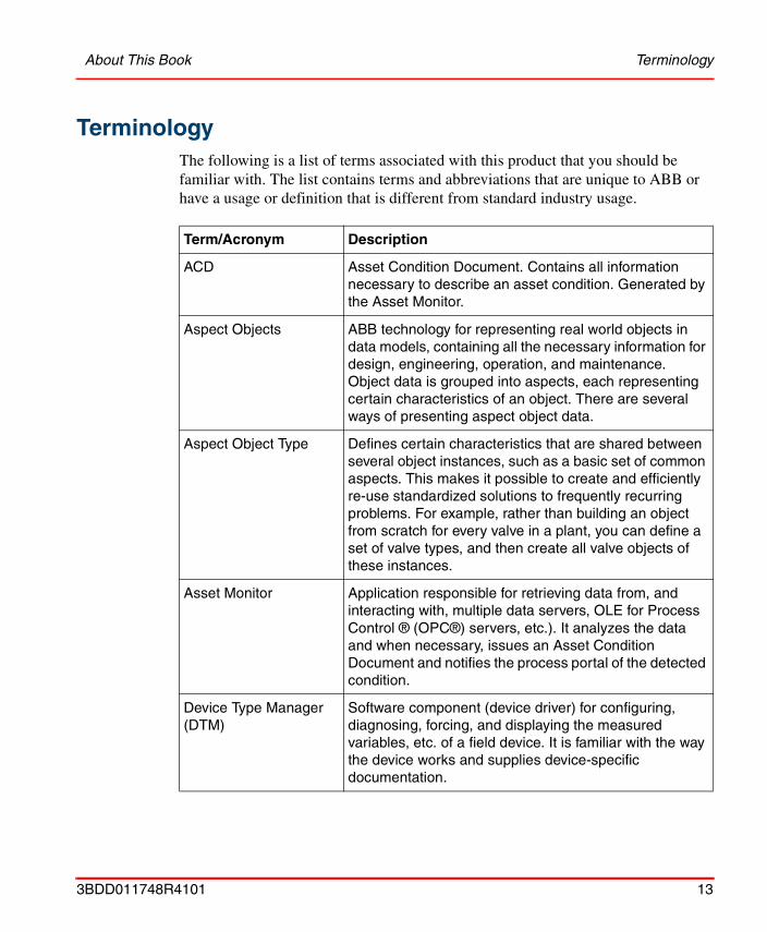
TerminologyThe following is a list of terms associated with this product that you should be familiar with. The list contains terms and abbreviations that are unique to ABB or have a usage or definition that is different from standard industry usage.
Term/Acronym Description
ACD Asset Condition Document. Contains all information necessary to describe an asset condition. Generated by the Asset Monitor.
Aspect Objects ABB technology for representing real world objects in data models, containing all the necessary information for design, engineering, operation, and maintenance. Object data is grouped into aspects, each representing certain characteristics of an object. There are several ways of presenting aspect object data.
Aspect Object Type Defines certain characteristics that are shared between several object instances, such as a basic set of common aspects. This makes it possible to create and efficiently re-use standardized solutions to frequently recurring problems. For example, rather than building an object from scratch for every valve in a plant, you can define a set of valve types, and then create all valve objects of these instances.
Asset Monitor Application responsible for retrieving data from, and interacting with, multiple data servers, OLE for Process Control ® (OPC®) servers, etc.). It analyzes the data and when necessary, issues an Asset Condition Document and notifies the process portal of the detected condition.
Device Type Manager (DTM)
Software component (device driver) for configuring, diagnosing, forcing, and displaying the measured variables, etc. of a field device. It is familiar with the way the device works and supplies device-specific documentation.
3BDD011748R4101 13
Terminology About This Book
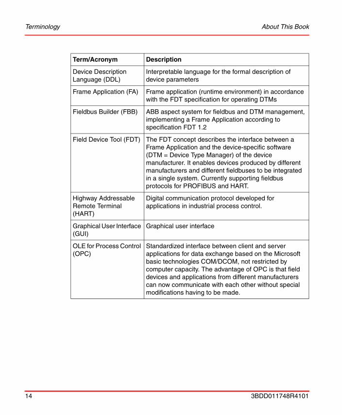
Device Description Language (DDL)
Interpretable language for the formal description of device parameters
Frame Application (FA) Frame application (runtime environment) in accordance with the FDT specification for operating DTMs
Fieldbus Builder (FBB) ABB aspect system for fieldbus and DTM management, implementing a Frame Application according to specification FDT 1.2
Field Device Tool (FDT) The FDT concept describes the interface between a Frame Application and the device-specific software (DTM = Device Type Manager) of the device manufacturer. It enables devices produced by different manufacturers and different fieldbuses to be integrated in a single system. Currently supporting fieldbus protocols for PROFIBUS and HART.
Highway Addressable Remote Terminal (HART)
Digital communication protocol developed for applications in industrial process control.
Graphical User Interface (GUI)
Graphical user interface
OLE for Process Control (OPC)
Standardized interface between client and server applications for data exchange based on the Microsoft basic technologies COM/DCOM, not restricted by computer capacity. The advantage of OPC is that field devices and applications from different manufacturers can now communicate with each other without special modifications having to be made.
Term/Acronym Description
14 3BDD011748R4101

About This Book Relevant Documentation
Relevant Documentation
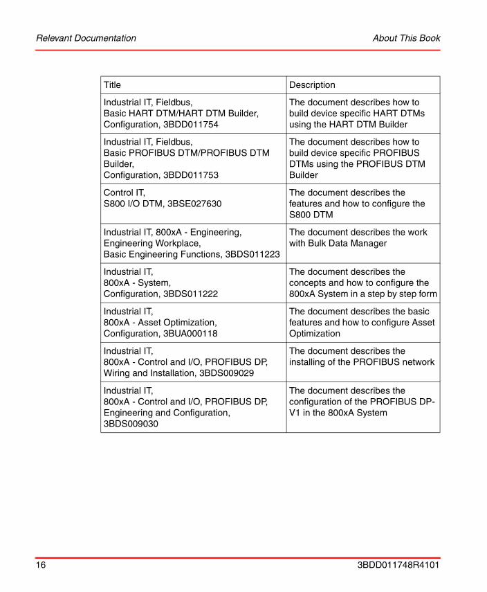
The table below contains a list of relevant documentation.
System Extension A solution or product developed with the Aspect Integrator Platform might typically contain several aspect systems, services, object types, and aspect objects. The System Extension mechanism enables a whole set of corresponding definition files to be read in at once. It makes it easy to load complex add-on solutions as options.
View Aspects can be presented in a number of ways depending on the task performed e.g. viewing or configuration. Each presentation form is called a view.
Title Description
Industrial IT, 800xA - Device Management, HART, Configuration, 3BDD011748
The document describes the basic features and how to configure the individual software components
Industrial IT, 800xA - Device Management, HART, Release Notes, 3BDS011768
This document contains the latest information about HART Device Management
Industrial IT, 800xA - Device Management, PROFIBUS, Release Notes, 3BDS011767
This document contains the latest information about PROFIBUS Device Management
Industrial IT, Device Library Wizard, User Instructions, 3BDD011857
The document describes how to use the Device Library Wizard.
Industrial IT, Device Library Wizard, Release Notes, 2PAA100110
This document contains the latest information about the Device Library Wizard
Term/Acronym Description
3BDD011748R4101 15
Relevant Documentation About This Book
Industrial IT, Fieldbus, Basic HART DTM/HART DTM Builder, Configuration, 3BDD011754
The document describes how to build device specific HART DTMs using the HART DTM Builder
Industrial IT, Fieldbus, Basic PROFIBUS DTM/PROFIBUS DTM Builder, Configuration, 3BDD011753
The document describes how to build device specific PROFIBUS DTMs using the PROFIBUS DTM Builder
Control IT, S800 I/O DTM, 3BSE027630
The document describes the features and how to configure the S800 DTM
Industrial IT, 800xA - Engineering, Engineering Workplace, Basic Engineering Functions, 3BDS011223
The document describes the work with Bulk Data Manager
Industrial IT, 800xA - System, Configuration, 3BDS011222
The document describes the concepts and how to configure the 800xA System in a step by step form
Industrial IT, 800xA - Asset Optimization, Configuration, 3BUA000118
The document describes the basic features and how to configure Asset Optimization
Industrial IT, 800xA - Control and I/O, PROFIBUS DP, Wiring and Installation, 3BDS009029
The document describes the installing of the PROFIBUS network
Industrial IT, 800xA - Control and I/O, PROFIBUS DP, Engineering and Configuration, 3BDS009030
The document describes the configuration of the PROFIBUS DP-V1 in the 800xA System
Title Description
16 3BDD011748R4101
Section 1 Introduction
Product Overview
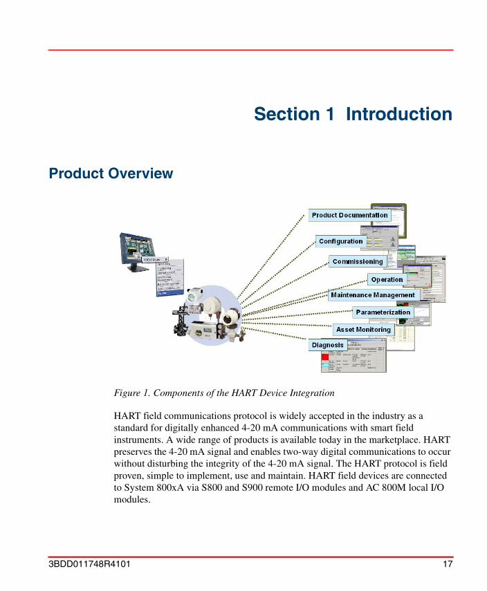
HART field communications protocol is widely accepted in the industry as a standard for digitally enhanced 4-20 mA communications with smart field instruments. A wide range of products is available today in the marketplace. HART preserves the 4-20 mA signal and enables two-way digital communications to occur without disturbing the integrity of the 4-20 mA signal. The HART protocol is field proven, simple to implement, use and maintain. HART field devices are connected to System 800xA via S800 and S900 remote I/O modules and AC 800M local I/O modules.
Figure 1. Components of the HART Device Integration
3BDD011748R4101 17
Section 1 Introduction
The HART Device Integration consists of a set of software components for the efficient planning, commissioning, and maintaining of field devices within ABB’s Industrial IT 800xA system.
The main components are:
• Fieldbus Builder PROFIBUS/HART
• OPC Server PROFIBUS/HART
• HART Device Integration Library
• Device Library Wizard (optional, must be downloaded from the ABB Solutionsbank)
• HART Multiplexer Connect (optional; to be entered from price list)
The HART Device Integration installs the necessary software components as well as preconfigured object types using appropriate "system extensions". This means that for new device objects, the functions of the installed components of this product are immediately available.
The HART Device Library contains tested and certified ABB and third party device objects, minimizing the effort of integration for 800xA system users. Each device is represented in the library by a device type object.
The system user will benefit from reduced engineering and commissioning time as well as in reduced maintenance costs. The result will be more effective use of fieldbus technology.
The object types in the Device Integration Package are created by ABB and tested for use in the 800xA system. ABB created these object types based on data provided by individual device vendors (e.g. DDs, Device specific DTMs and Asset Monitor behavior specifications), which ABB relies on as accurately reflecting the actual device specification and behavior. Therefore, ABB cannot assume liability for events that are caused by devices that are not functioning according to fieldbus standards, or device specifications, or for events that are caused by mismatches between the device behavior and the input data provided by the device vendor.
18 3BDD011748R4101
Section 1 Introduction Notes for use
Notes for useThe HART Device Integration must be installed on the following computers:
• Any workstation from which the user wants to have access to field devices via FDT/DTM.
• Any Connectivity Server installed in the system.
• Any Aspect Server installed in the system.
During installation of the HART Device Integration a Device Integration Library is also implemented in the system. We recommend that only the field devices deployed in the system by the library are used for fieldbus engineering.
We recommend that the Device Integration is installed on every PC used in the system, except Thin Client nodes.
It is only allowed to run one OPC Server PROFIBUS/HART on a single Connectivity Server. Each control network containing the aspect for OPC Server PROFIBUS/HART connectivity needs therefore its own Connectivity Server.
Asset Monitors, CMMS Connectivity and Device Management System (DMS) will only run with the HART Device Integration, if the Asset Optimization option and the related CMMS and DMS software is installed and licensed in the system.
The device object types in the Device Integration Library have been tested together with the associated real field devices in the 800xA system. This assures the user full functionality without additional integration effort.
Licenses for device-specific DTMs are not subject to the System 800xA licensing arrangements and are not included in the PROFIBUS Device Integration. Licenses for device-specific DTMs should be applied for from the relevant device manufacturer.
Unless described in more detail, object types and aspects of the Device Integration software are configured and may not be modified by the user. ABB Service must be informed before the user makes any changes to the aspects described in this document.
3BDD011748R4101 19

Notes for use Section 1 Introduction
ABB cannot guarantee an operable 800xA system if device object types are created/modified manually. Only tested software (DTMs) may be installed on the system computer. All software supplied in the Device Integration meets this requirement.
Additional information can be found in Section 5, HART Device Integration Library.
20 3BDD011748R4101
Section 1 Introduction Components and Functions
Components and Functions
Fieldbus Builder PROFIBUS/HART with OPC Server
Fieldbus Builder PROFIBUS/HART
The Fieldbus Builder PROFIBUS/HART is the main component within the Device Integration package. It forms the FDT compliant interface between Process Portal A as a part of the 800xA core system and the field devices represented by its DTMs (Device Type Manager).
The main tasks for HART devices are:
• Managing (add, move, remove, or copy) HART devices connected to local I/O or remote I/O
• Topology planning down to HART devices
• Assignment of HART devices to I/O channels
• DTM call up from System 800xA clients
• Comparison of field device on- and offline data
• Upload, download and commissioning
OPC Server PROFIBUS/HART
Today, smart field devices are able to supply a multiplicity of information via their DTM. The OPC Server PROFIBUS/HART enables access to HART field device data without requiring additional field wiring. This means that business level applications, such as 800xA Asset Optimization can access connected field device data. The OPC Server PROFIBUS/HART is designed to provide specific field device data, device status, and diagnostic data to Asset Optimization Server.
Please see Section 3, Fieldbus Builder PROFIBUS/HART on page 71 for detailed information.
3BDD011748R4101 21
Components and Functions Section 1 Introduction
OPC connectivity is prepared for all field device objects, included in the field device library.
Due to the nature of the HART protocol and the necessary routing through the system, update rate for HART data may reads several 10 seconds.
22 3BDD011748R4101
Section 1 Introduction HART Device Integration Library
HART Device Integration Library
The HART Field Device Library contains preconfigured ABB and third party field device objects enhanced with the essential Aspects for:
• Product Documentation
• Asset Monitoring
• Computerized Maintenance Management System (CMMS Connectivity)
• Device Management System (DMS Integration)
• Configuration, Parameterization, Operation via DTM
Product Documentation
Product Documentation is directly available at the device object. Key product data are bundled in convenient electronic format. Thereby documents like Data Sheet, Installation, Configuration, and Operation Manual as well as maintenance and service manual are accessible via mouse click.
Asset Monitoring
Asset Monitor, Asset Reporter and Asset Viewer acquire and analyze asset status and condition information. They notify operators and maintenance personnel when an abnormal condition calls for maintenance action.
Maintenance Management
CMMS Connectivity provides the seamless integration of the Computerized Maintenance Management Systems (CMMS) into the Industrial IT system environment. Asset related maintenance information is accessed via standard, preconfigured CMMS views allowing for the quick and efficient assessment of maintenance needs and status.
DMS Integration
DMS Connectivity integrates the calibration management system (DMS) from the Meriam Instruments into the 800xA System and allows plant personnel to monitor field devices for calibration information and streamlines the maintenance workflow.
3BDD011748R4101 23
HART Device Integration Library Section 1 Introduction
Device Type Manager
DTMs are the configuration and management software component for a field device. It is familiar with all of the device’s rules to ensure the correctness of the device configuration.
The DTM contains graphical user dialogs essential for device configuration, parameterization, diagnostics, and maintenance and enables offline engineering without requiring the connected field devices. In addition, online engineering with connected field devices is also possible.
During setup of the HART Device Integration Library the following DTMs are installed:
• Basic HART DTM/HART DTM BuilderAs it uses device-specific templates, the Basic HART DTM also enables custom access to the corresponding device.
• S800 I/O DTMUsed for the configuration and diagnosis of HART devices, which are connected to a S800 module.
• S900 I/O DTMUsed for the configuration and diagnosis of HART devices, which are connected to a S900 module.
• Device specific DTMs Additional DTMs are prepared for installation from the hard disk, which can be installed directly from the Device Integration setup program or later on via Install DTM Aspect directly at the object type.
Please read the HART Device Integration Release Notes for detailed information about limits and additional licenses may be required for some DTMs.
24 3BDD011748R4101
Section 1 Introduction Device Library Wizard and Device Object Types (optional)
Device Library Wizard and Device Object Types (optional)For easy integration of devices into the Industrial IT 800xA environment ABB provides a continuously increasing set of pre-integrated device types for PROFIBUS protocol in the form of device object types.
Pre-integrated device types for the Industrial IT 800xA environment are available from ABB Solutionsbank for all supported fieldbus protocols in the form of device object types.
The Device Library Wizard is a tool that is used for adding these separately delivered device object types to the PROFIBUS Device Integration Library of an 800xA system. It will be installed and operate on an Industrial IT 800xA system node.
HART Multiplexer ConnectHART Multiplexer Connect integrates specific DTMs for Multiplexer, OPC communication components and HART Multiplexer networks to the 800xA system. The integration allows to collect, configure, calibrate and diagnosis HART devices, connected to other DCS/PLC than 800xA system which not allows direct access to specific device HART data. Standard HART Multiplexer hardware can be used. As a result the benefit of the HART Device Integration Library and its aspect functionality can be used also for those HART networks, which are not connected to AC 800M controller.
Please see Section 6, Device Library Wizard (optional) on page 141 for detailed information.
HART Multiplexer Connect is a separate option to the HART Device Integration and needs to be ordered from the price list.
HART Multiplexer network configuration is described in Appendix A, HART Multiplexer Connect.
3BDD011748R4101 25
New In This Release Section 1 Introduction
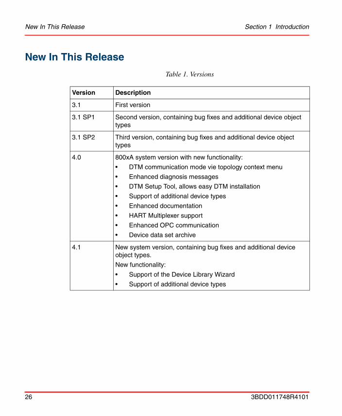
New In This Release
Table 1. Versions
Version Description
3.1 First version
3.1 SP1 Second version, containing bug fixes and additional device object types
3.1 SP2 Third version, containing bug fixes and additional device object types
4.0 800xA system version with new functionality:
• DTM communication mode vie topology context menu
• Enhanced diagnosis messages
• DTM Setup Tool, allows easy DTM installation
• Support of additional device types
• Enhanced documentation
• HART Multiplexer support
• Enhanced OPC communication
• Device data set archive
4.1 New system version, containing bug fixes and additional device object types.
New functionality:
• Support of the Device Library Wizard
• Support of additional device types
26 3BDD011748R4101

Section 1 Introduction Prerequisites and Requirements
Prerequisites and RequirementsFor prerequisites and requirements, please refer to IndustrialIT/System Installation 3BSE034678, stored on the 800xA system DVD/CDs.
Intended UserThe configuration document is designed specifically for planning engineers, commissioning engineers, and maintenance personnel. Those using this document should be familiar with the basic method of operation of the protocol.
Product SupportContact ABB technical support for assistance in problem reporting.
3BDD011748R4101 27

Product Support Section 1 Introduction
28 3BDD011748R4101
Section 2 Getting Started
OverviewThis section uses actual examples to describe how device objects with asset monitors are used in a fieldbus system and how DTMs are started. Information about DTM functionality can be found in each device-specific description.
Prerequisites and RequirementsThe following requirements must be met, in order to be able to carry out the actions described in this section:
• All necessary software is installed on the related system node. Please refer to Industrial IT, 800xA - System, Installation 3BSE034678 for detailed information.
• DCOM settings for HART Device Integration components are adapted according Industrial IT, 800xA - System, Post Installation Setup 3BUA000156R4101 manual.
• A directory must be shared for DTM access on every system node. Please refer to Industrial IT, 800xA - System, Post Installation Setup 3BUA000156R4101 manual, section “Shared Folder for PROFIBUS and HART Device Integration”
• An 800xA system has been created and started.
This section does not include configuration parts of HART Multiplexer Connect. The HART Multiplexer integration is described in Appendix A, HART Multiplexer Connect.
3BDD011748R4101 29
Fieldbus topology in the 800xA system Section 2 Getting Started
• The following system extensions have been added:
– AC 800M/C Connect (if AC 800M is used)
– Fieldbus Builder PROFIBUS/HART
– HART Device Integration Library - Basics
– HART Device Integration Library - Asset Monitoring (optional, requires Asset Optimization installation and loading of the relevant system extensions)
• The Plant Explorer Workplace has been started.
• The user has configuration and download access rights.
Fieldbus topology in the 800xA system
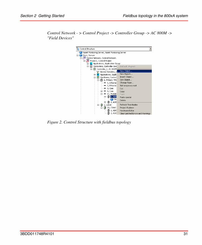
Once an 800xA system has been started, a fieldbus topology starting at the controller and ending at the field device can be created in the Control Structure of the Plant Explorer. Starting with the root node, the simplest example of a fieldbus system for PROFIBUS and HART is set up as follows using the Plant Explorer context menu (right mouse button):
30 3BDD011748R4101
Section 2 Getting Started Fieldbus topology in the 800xA system
Control Network - > Control Project -> Controller Group -> AC 800M -> "Field Devices"
Figure 2. Control Structure with fieldbus topology
3BDD011748R4101 31
Preparing device object types for usage Section 2 Getting Started
Preparing device object types for usageThe HART device objects are present in the Object Type Structure once the system extensions of the HART Device Integration Library have been loaded into the 800xA system.
Some device object types which have been implemented in the 800xA system using the HART Device Integration Library have a device-specific DTM for device configuration, parameterization and operation. The device-specific DTM may also include licensing, whereby the end user has to purchase the license separately directly from the device manufacturer.
The HART Device Integration Package copies the installation routines of the DTMs to the local hard drive. Afterwards the DTMs can be executed via the relevant device object type.
In case, that the Device Library Wizard is used to extend the HART Device Integration Library, the Device Type Manager (DTM) is installed automatically on the 800xA’s system node.
License for device-specific DTMs are not subject to the System 800xA licensing arrangements and are not included in the HART Device Integration Package. Licenses for device-specific DTMs have to be applied for from the relevant device manufacturer.
Device-specific DTMs need to be installed on every 800xA system node on which the HART Device Integration is executed. The DTM-specific licensing arrangements need to taken into account.
Device object types cannot be used or instantiated if the associated DTM is not installed.
32 3BDD011748R4101
Section 2 Getting Started Installation of Device Type Manager (DTM)
Installation of Device Type Manager (DTM)
The installation of the Device Type Manager (DTM) is mandatory for object types, which are used in the field device topology. In case, that the DTM is already installed on the system nodes, this subsection is not applicable.
The following steps need to be carried out for the relevant object type, if the device specific DTM is not installed yet on the system node:
1. Switch to the Plant Explorer Object Type Structure.
2. Open the Field Devices folder.
3. A folder structure containing the various device objects appears. Click "+" to open the next level of the partial tree and select the required device object.
4. Select the Install <DTM> aspect, if applicable.
This subsection can be skipped, if the device object type is installed separately via Device Library Wizard.
Notice, that it is mandatory to install specific Device Type Manager (DTM) before the device object is instantiated in Plant Explorers Control Structure. That applies also to device objects, coming into the system as instances in an already created Control Structure via import, e.g. during upgrade or recovery procedures.
Detailed information for upgrade procedure are described in the 800xA system upgrade manual.
DTMs can be installed via setup tool, located inStart -> All Programs -> ABB Industrial IT 800xA -> Device Mgmt - HART -> HART DTM Setup Toolor via the steps described below:
For HART, object types are stored inside the Field Devices catalog. The object types in the Basics, Object Type Group catalog are generic object types which are not designed for direct use. Please use device types from the HART Actuators and HART Transmitter object type groups instead.
The Basic HART DTM is automatically assigned to device object types which do not have a specific DTM and therefore also do not have an Install <DTM> aspect. This DTM is already installed with the HART Device Integration Package.
3BDD011748R4101 33
Installation of Device Type Manager (DTM) Section 2 Getting Started
5. Double-click on the Install <DTM> aspect to start the associated installation program.
6. Follow the instruction of the DTM setup program.
Further information about device object types can be found in Section 5, HART Device Integration Library.
Steps 1 to 6 need to be carried out on every 800xA system node on which the HART Device Integration has been installed.
34 3BDD011748R4101
Section 2 Getting Started System 800xA Server Path Settings
System 800xA Server Path Settings
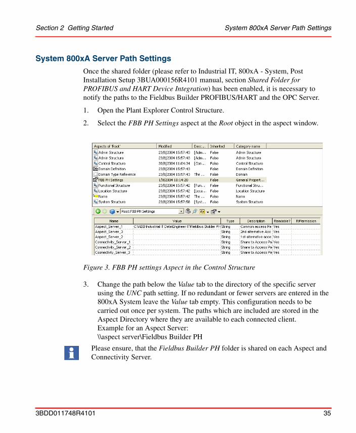
Once the shared folder (please refer to Industrial IT, 800xA - System, Post Installation Setup 3BUA000156R4101 manual, section Shared Folder for PROFIBUS and HART Device Integration) has been enabled, it is necessary to notify the paths to the Fieldbus Builder PROFIBUS/HART and the OPC Server.
1. Open the Plant Explorer Control Structure.
2. Select the FBB PH Settings aspect at the Root object in the aspect window.
3. Change the path below the Value tab to the directory of the specific server using the UNC path setting. If no redundant or fewer servers are entered in the 800xA System leave the Value tab empty. This configuration needs to be carried out once per system. The paths which are included are stored in the Aspect Directory where they are available to each connected client. Example for an Aspect Server: \\aspect server\Fieldbus Builder PH
Figure 3. FBB PH settings Aspect in the Control Structure
Please ensure, that the Fieldbus Builder PH folder is shared on each Aspect and Connectivity Server.
3BDD011748R4101 35

System 800xA Server Path Settings Section 2 Getting Started
4. Click [Apply].
5. Change to the configuration mode of the FBB PH Settings aspect.
6. Select a Server in the left side window.
All Aspect Server and Connectivity Server with its share folder shall be included in the FBB PH Settings aspect. If more Connectivity Server then configuration rows of the FBB PH Settings are connected to the system, additional rows can be included manually.
Figure 4. FBB PH Settings config menu
Figure 5. Configuration Mode
36 3BDD011748R4101
Section 2 Getting Started System 800xA Server Path Settings
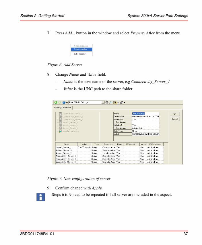
7. Press Add... button in the window and select Property After from the menu.
8. Change Name and Value field.
– Name is the new name of the server, e.g Connectivity_Server_4
– Value is the UNC path to the share folder
9. Confirm change with Apply.
Figure 6. Add Server
Figure 7. New configuration of server
Steps 6 to 9 need to be repeated till all server are included in the aspect.
3BDD011748R4101 37
Pre-configuration of the OPC Server PROFIBUS/HART Section 2 Getting Started
Pre-configuration of the OPC Server PROFIBUS/HART
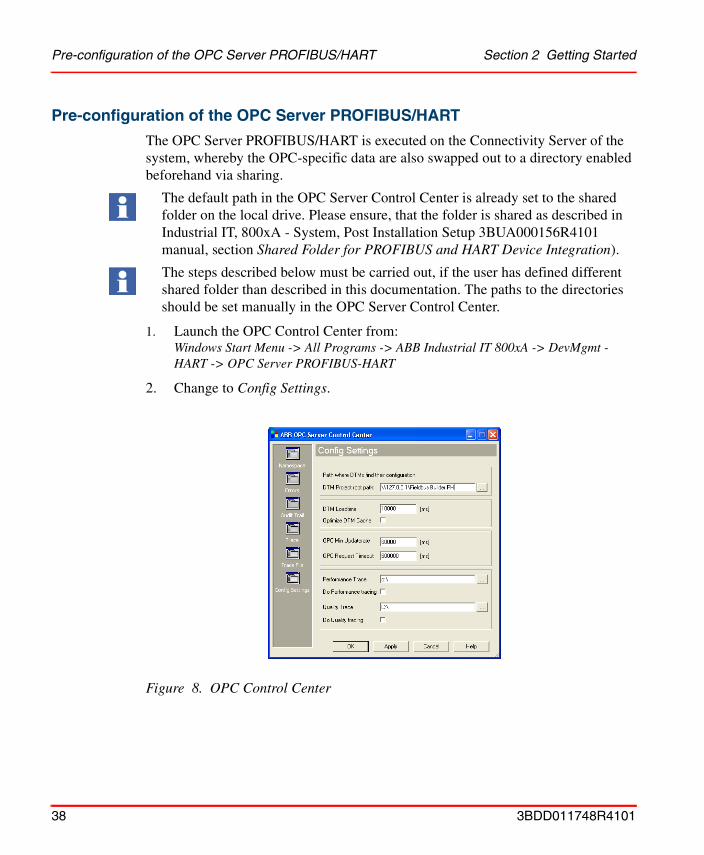
The OPC Server PROFIBUS/HART is executed on the Connectivity Server of the system, whereby the OPC-specific data are also swapped out to a directory enabled beforehand via sharing.
1. Launch the OPC Control Center from:Windows Start Menu -> All Programs -> ABB Industrial IT 800xA -> DevMgmt - HART -> OPC Server PROFIBUS-HART
2. Change to Config Settings.
The default path in the OPC Server Control Center is already set to the shared folder on the local drive. Please ensure, that the folder is shared as described in Industrial IT, 800xA - System, Post Installation Setup 3BUA000156R4101 manual, section Shared Folder for PROFIBUS and HART Device Integration).
The steps described below must be carried out, if the user has defined different shared folder than described in this documentation. The paths to the directories should be set manually in the OPC Server Control Center.
Figure 8. OPC Control Center
38 3BDD011748R4101
Section 2 Getting Started Pre-configuration of the OPC Server PROFIBUS/HART
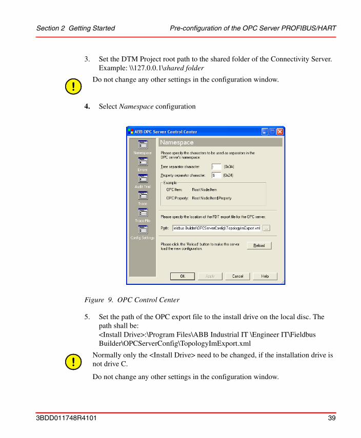
3. Set the DTM Project root path to the shared folder of the Connectivity Server.Example: \\127.0.0.1\shared folder
4. Select Namespace configuration
5. Set the path of the OPC export file to the install drive on the local disc. The path shall be: <Install Drive>:\Program Files\ABB Industrial IT \Engineer IT\Fieldbus Builder\OPCServerConfig\TopologyImExport.xml
Do not change any other settings in the configuration window.
Figure 9. OPC Control Center
Normally only the <Install Drive> need to be changed, if the installation drive is not drive C.
Do not change any other settings in the configuration window.
3BDD011748R4101 39
Pre-configuration of the OPC Server PROFIBUS/HART Section 2 Getting Started
6. Click [Apply] and [OK].
Repeat steps 1 to 6 locally as required for the relevant server if redundant or additional Connectivity Servers are used.
If the OPC Server PROFIBUS/HART is already running it will need to be restarted in the 800xA system after configuration of the OPC Control Center (see also OPC Server assignment to a Connectivity Server on page 43).
In the Plant Explorer, switch toService Structure -> OpcDA Connectors -> [Service group, name of the group was given beforehand during configuration]-> [Configuration tab] -> Deselect enable ->[apply button] -> Select enable again ->[apply].
40 3BDD011748R4101
Section 2 Getting Started Pre-commissioning Control Networks, AC 800M and OPC
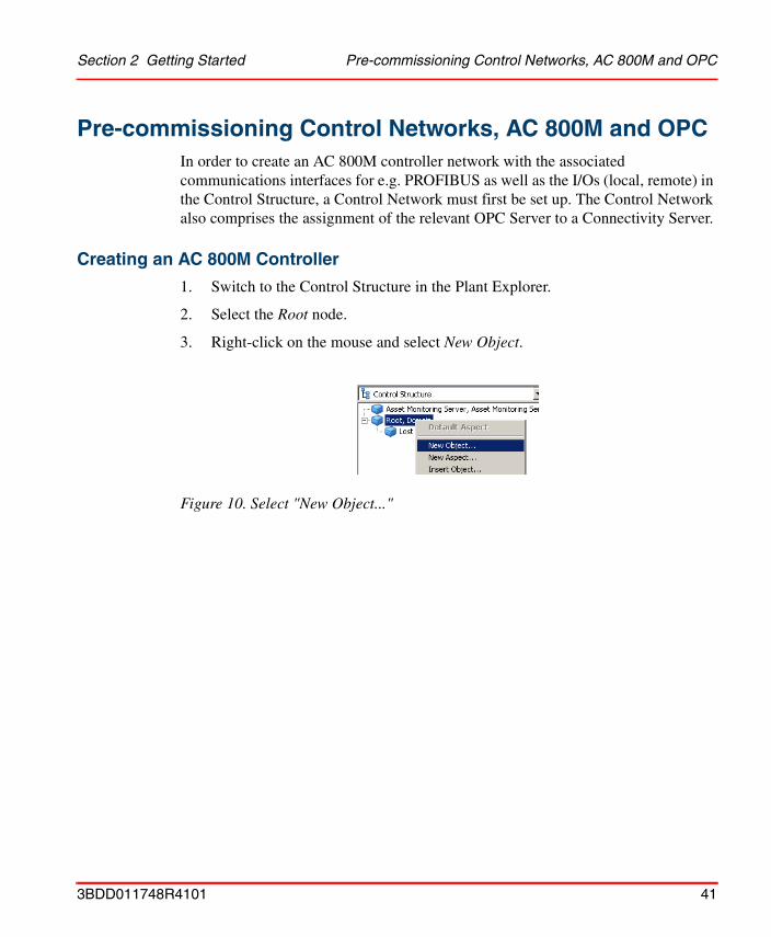
Pre-commissioning Control Networks, AC 800M and OPCIn order to create an AC 800M controller network with the associated communications interfaces for e.g. PROFIBUS as well as the I/Os (local, remote) in the Control Structure, a Control Network must first be set up. The Control Network also comprises the assignment of the relevant OPC Server to a Connectivity Server.
Creating an AC 800M Controller
1. Switch to the Control Structure in the Plant Explorer.
2. Select the Root node.
3. Right-click on the mouse and select New Object.
Figure 10. Select "New Object..."
3BDD011748R4101 41
Creating an AC 800M Controller Section 2 Getting Started
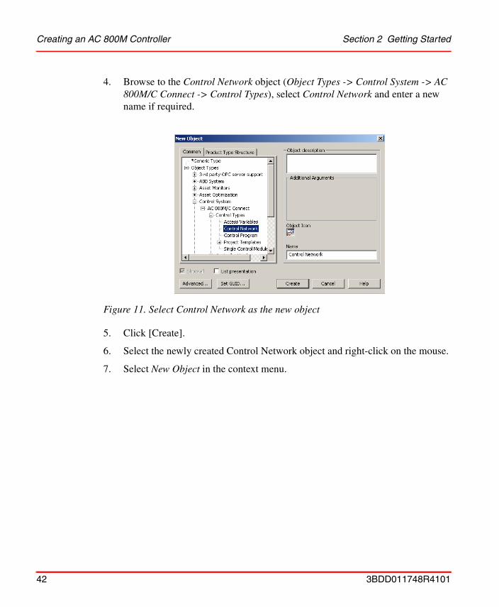
4. Browse to the Control Network object (Object Types -> Control System -> AC 800M/C Connect -> Control Types), select Control Network and enter a new name if required.
5. Click [Create].
6. Select the newly created Control Network object and right-click on the mouse.
7. Select New Object in the context menu.
Figure 11. Select Control Network as the new object
42 3BDD011748R4101
Section 2 Getting Started OPC Server assignment to a Connectivity Server
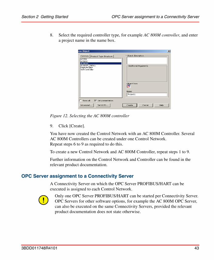
8. Select the required controller type, for example AC 800M controller, and enter a project name in the name box.
9. Click [Create].
You have now created the Control Network with an AC 800M Controller. Several AC 800M Controllers can be created under one Control Network. Repeat steps 6 to 9 as required to do this.
To create a new Control Network and AC 800M Controller, repeat steps 1 to 9.
Further information on the Control Network and Controller can be found in the relevant product documentation.
OPC Server assignment to a Connectivity Server
A Connectivity Server on which the OPC Server PROFIBUS/HART can be executed is assigned to each Control Network.
Figure 12. Selecting the AC 800M controller
Only one OPC Server PROFIBUS/HART can be started per Connectivity Server. OPC Servers for other software options, for example the AC 800M OPC Server, can also be executed on the same Connectivity Servers, provided the relevant product documentation does not state otherwise.
3BDD011748R4101 43
OPC Server assignment to a Connectivity Server Section 2 Getting Started
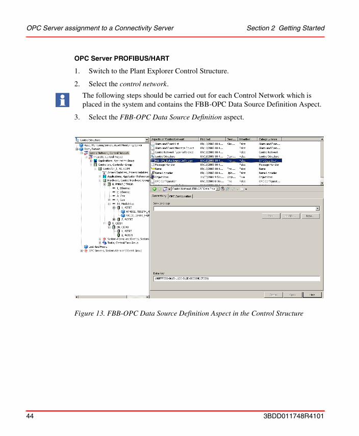
OPC Server PROFIBUS/HART
1. Switch to the Plant Explorer Control Structure.
2. Select the control network.
3. Select the FBB-OPC Data Source Definition aspect.
The following steps should be carried out for each Control Network which is placed in the system and contains the FBB-OPC Data Source Definition Aspect.
Figure 13. FBB-OPC Data Source Definition Aspect in the Control Structure
44 3BDD011748R4101
Section 2 Getting Started OPC Server assignment to a Connectivity Server
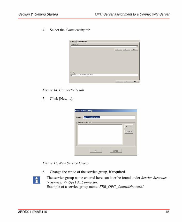
4. Select the Connectivity tab.
5. Click [New…].
6. Change the name of the service group, if required.
Figure 14. Connectivity tab
Figure 15. New Service Group
The service group name entered here can later be found under Service Structure -> Services -> OpcDA_Connector.Example of a service group name: FBB_OPC_ControlNetwork1
3BDD011748R4101 45

OPC Server assignment to a Connectivity Server Section 2 Getting Started
7. Click [Add...].
8. Select the Connectivity Server on which the OPC Server PROFIBUS/HART is installed and running.
9. Click the [OK] button in the main window.
10. The OPC Server is now configured for data access to device-internal data via OPC communication. .
Each control network needs a unique service group name and shall not given twice in the system
Figure 16. Adding a service provider
If redundant Connectivity Servers are used in the system then they need to be assigned to the same Control Network. To do this, repeat steps 1 to 10 for each redundant Connectivity Server.
In cases where more than just one Control Network is instanced, steps 1 to 10 are also repeated for these Control Networks.
Different service group names and different Connectivity Servers should be used.
46 3BDD011748R4101

Section 2 Getting Started OPC Server assignment to a Connectivity Server
AC 800M OPC Server
Parameter display and faceplates are mainly supplied with data via the AC 800M OPC Server. Configuration of this OPC Server needs to repeat steps 1 to 10 on the OPC Data Source Definition aspect.
Information about configuring and starting the AC 800M OPC Server can be found in the relevant product documentation.
Figure 17. OPC Server configuration complete
The OPC Server PROFIBUS/HART and the AC 800M OPC Server do not necessarily need to be operated on the same Connectivity Server.
3BDD011748R4101 47
Pre-configuration of the AC 800M controller Section 2 Getting Started
Pre-configuration of the AC 800M controller
To ensure error-free communication for a field device with a DTM, an additional setting must be made for the AC 800M controller in the Plant Explorer.
In order that field devices can be accessed with DTM (Device Type Manager) via the AC 800M controller, the communication path (Tool Routing) must be enabled in each controller.
Tool Routing is disabled by default. In order to activate it, the processor module of the AC 800M controller, e.g. PM860/TP860, is selected in the Control Structure.
The Control Properties aspect appears in the aspect window. Select the aspect to open an overview of the various properties of the module in the main Plant Explorer window. One of the property entries is TOOLROUTING.
Only when Tool Routing is enabled, communication with DTMs for field devices is possible in the 800xA system.
48 3BDD011748R4101
Section 2 Getting Started Pre-configuration of the AC 800M controller
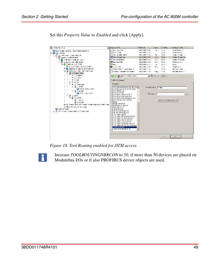
Set this Property Value to Enabled and click [Apply].
Figure 18. Tool Routing enabled for DTM access
Increase TOOLROUTINGNBRCON to 50, if more than 50 devices are placed on Modulebus I/Os or if also PROFIBUS device objects are used.
3BDD011748R4101 49
Setting up a Fieldbus Topology for HART Section 2 Getting Started
Setting up a Fieldbus Topology for HARTTogether with the AC 800M Controller, the 800xA System is capable of setting up a HART communication both by means of local S800 modules and also via remote I/Os and the PROFIBUS. This section describes a sample set-up for the S800 I/O modules. The following steps have been performed in the Plant Explorer workplace in the Control Structure. The S800 I/O modules can also be instanced via the Control Builder M. HART devices can be instanced only via Plant Explorers Control Structure.
Local S800 modules on the AC 800M controller
1. Open the Plant Explorer workplace.
2. Switch to the Control Structure.
3. Open the substructure below the Project object.
4. To place a S800 local I/O on the controller, select the Modulebus object.
5. Right-click on the mouse and select New Object.
6. Browse to the required S800 module, e.g. AI895.
7. Enter the slot number of the module placed, e.g. 1, in the Name box.
8. Click [Create].
The module is instanced both on the slot number in the Control Structure of the Plant Explorer and in the Control Builder M.
Repeat steps 4 to 8 until all of the desired modules have been placed.
S800 local I/Os always start at slot 1.
Information relating to S800 modules and instancing instructions can be found in the relevant product documentation.
50 3BDD011748R4101
Section 2 Getting Started PROFIBUS Remote I/O and HART modules
PROFIBUS Remote I/O and HART modules
1. Open Plant Explorer workplace.
2. Switch to the Control Structure.
3. Open the substructure below the Project object.
4. To place a PROFIBUS communication interface on the controller, select the Hardware object.
5. Right-click on the mouse and select New Object in the context menu.
6. Browse to the required communication interface, e.g. CI854 for PROFIBUS.
7. Enter the CEX bus number of the module placed, e.g. 1, in the name box.
8. Click [Create].
9. To place an S800 communication interface on the PROFIBUS, select the CI854 object.
10. Right-click on the mouse and select New Object.
11. Browse to the required S800 gateway, e.g. CI840.
DTMs use acyclic communications to exchange data with field devices (DPV1). CI854(A) supports this type of communication, while CI851 does not.
The CEX bus is the internal communication bus for data transmission between AC 800M controller and the connected communication interfaces. The communication interfaces are located on the left side of the controller and are numbered from left to right. Starting number is 1.
Example:If the CI854 module is the second module on this bus, the number 2 must be entered in the name box.
Information relating to CI854 modules and instancing instructions can be found in the relevant product documentation.
The settings for the PROFIBUS master settings are listed in the product documentation of the CI854 (PROFIBUS DP - Engineering and Configuration, 3BDS009030).
DTMs use acyclic communications to exchange data with field devices (DPV1). CI840 supports this type of communication, while CI830 does not.
3BDD011748R4101 51
PROFIBUS Remote I/O and HART modules Section 2 Getting Started
12. Enter the PROFIBUS address of the gateway placed, e.g. 20, in the name box.
13. Click [Create].
14. To place S800 modules on the CI840, select the CI840 object.
15. Right-click on the mouse and select New Object.
16. Browse to the required S800 module, e.g. AI895.
17. Enter the slot number of the module placed, e.g. 1, in the Name box.
18. Click [Create].
The remote I/O with module is instanced both in the Control Structure of the Plant Explorer and in the Control Builder M.
Repeat steps 13 to 17 until all of the desired modules have been placed on the remote I/O.
S800 I/Os always start at slot 1.
Information relating to S800 modules and instancing instructions can be found in the relevant product documentation.
The above steps should be applied analogously for instancing of an S900 Remote I/O, although in this case the S900 modules and the specific gateways are selected.
52 3BDD011748R4101
Section 2 Getting Started Pre-settings for Instantiation
Pre-settings for Instantiation
Instantiation of field devices are only possible with the Fieldbus Builder PROFIBUS/HART in Communication disabled mode. If Communication enabled mode is active, it MUST be deactivated for device instantiation (Communication disabled).
Two possibilities are available to set the Fieldbus Builder in Communication disabled:
• Via context menu of the Fieldbus Management aspect at the device object.
• Via Device Functions ... context menu in the Control Structure of the Plant Explorer workplace.
Communication mode via Fieldbus Management aspect
1. Select the CI854 or Modulebus object in the Plant Explorers Control Structure.
2. Select the Fieldbus Management aspect in the Aspect window.
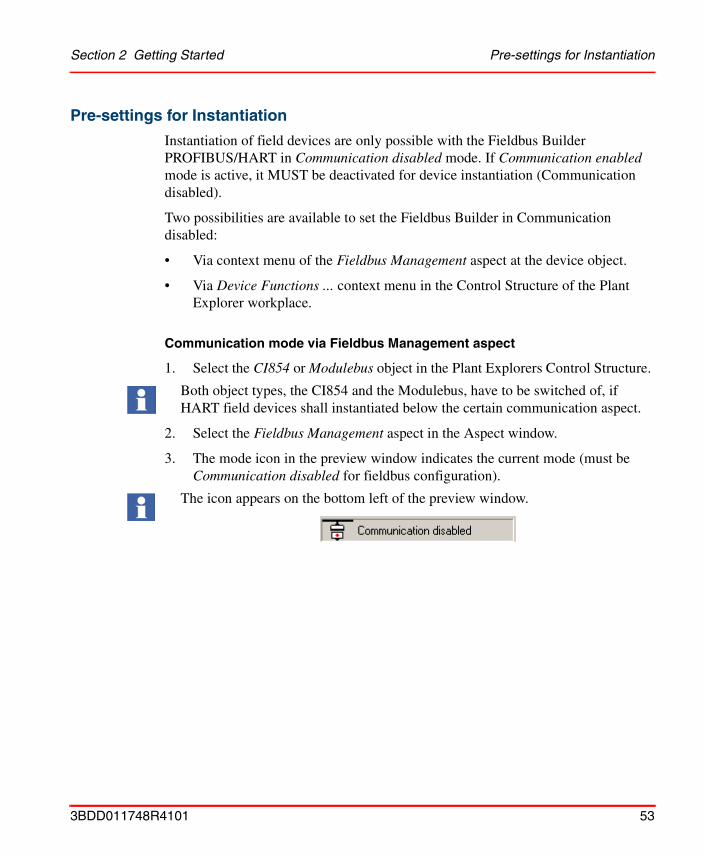
3. The mode icon in the preview window indicates the current mode (must be Communication disabled for fieldbus configuration).
Both object types, the CI854 and the Modulebus, have to be switched of, if HART field devices shall instantiated below the certain communication aspect.
The icon appears on the bottom left of the preview window.
3BDD011748R4101 53
Pre-settings for Instantiation Section 2 Getting Started
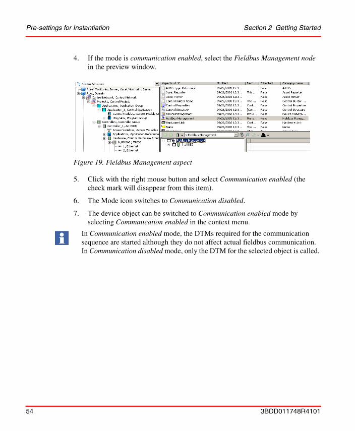
4. If the mode is communication enabled, select the Fieldbus Management node in the preview window.
5. Click with the right mouse button and select Communication enabled (the check mark will disappear from this item).
6. The Mode icon switches to Communication disabled.
7. The device object can be switched to Communication enabled mode by selecting Communication enabled in the context menu.
Figure 19. Fieldbus Management aspect
In Communication enabled mode, the DTMs required for the communication sequence are started although they do not affect actual fieldbus communication. In Communication disabled mode, only the DTM for the selected object is called.
54 3BDD011748R4101

Section 2 Getting Started Pre-settings for Instantiation
Communication mode via Device Functions menu
1. Select the CI854 object in the Plant Explorers Control Structure.
2. Click with the right mouse button to open the context menu.
3. Select Device Functions... in the context menu.
4. The sub menu of Device Functions ... indicates the current mode (will be Communication disabled for fieldbus configuration).
Figure 20. Device Functions ...
The sub menu allows also changing the mode by selecting the menu item.
3BDD011748R4101 55

Instancing of HART Device Objects Section 2 Getting Started
Instancing of HART Device Objects
Instancing HART device objects can be performed only in the Plant Explorers Control Structure.
Field device objects of the HART Device Library are integrated into the fieldbus topology as follows.
HART Device Objects below HART I/O modules
If they are located below multi-channel I/O modules, field devices that support the HART protocol must be assigned to the relevant channel of the I/O module. For a description of how to do this, see Channel allocation on I/O modules on page 59.
Field device of the HART Device Library are integrated into the fieldbus topology as follows:
1. Open Plant Explorer workplace.
2. Switch to the Control Structure.
3. Open the substructure below the Project object.
4. Select the object below which the device object will be placed, e.g. AI895.
5. Click with the right mouse button to open the context menu.
Instancing HART devices is possible via steps described in this section as well as via Bulk Data Manager. An example for Bulk Data process is described in Bulk Data Management on page 192.
The HART Device Integration Library include HART Device Objects, prepared for use of vendor specific DTM. In this case the DTM has to be installed manually before instantiation. For a description of how to install specific DTMs, see Installation of Device Type Manager (DTM) on page 33.
Vendor specific DTMs sometimes include a license mechanism to run the DTM without limitations. Only the DTM software is part of the Device Integration Package, the specific license of a DTM not. The DTM license has to be ordered separately from the DTM vendor. Licenses for a DTM are not included in the 800xA licensing.
56 3BDD011748R4101
Section 2 Getting Started Instancing of HART Device Objects
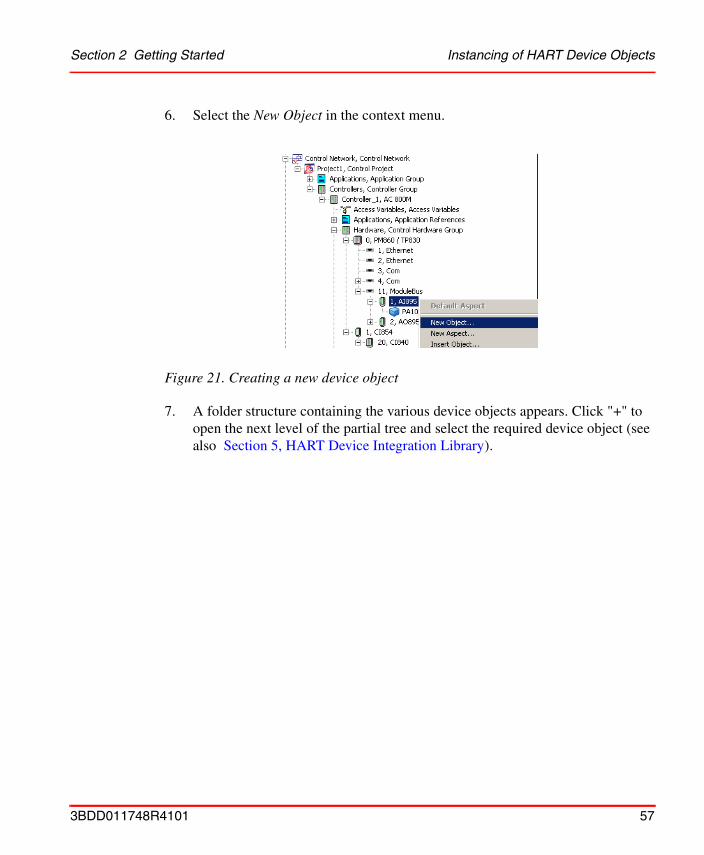
6. Select the New Object in the context menu.
7. A folder structure containing the various device objects appears. Click "+" to open the next level of the partial tree and select the required device object (see also Section 5, HART Device Integration Library).
Figure 21. Creating a new device object
3BDD011748R4101 57
Instancing of HART Device Objects Section 2 Getting Started
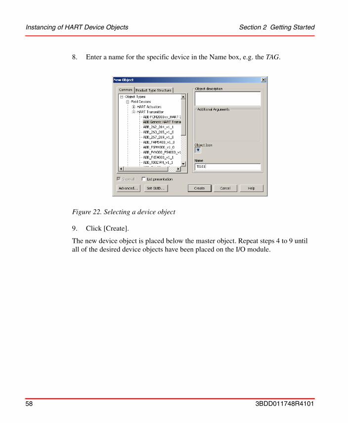
8. Enter a name for the specific device in the Name box, e.g. the TAG.
9. Click [Create].
The new device object is placed below the master object. Repeat steps 4 to 9 until all of the desired device objects have been placed on the I/O module.
Figure 22. Selecting a device object
58 3BDD011748R4101
Section 2 Getting Started Instancing of HART Device Objects
Channel allocation on I/O modules
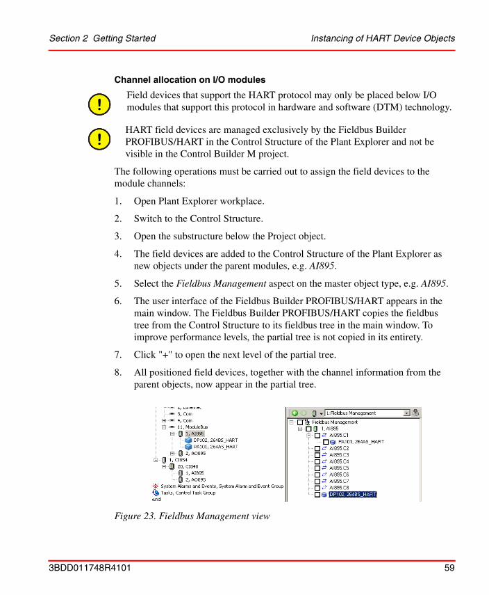
The following operations must be carried out to assign the field devices to the module channels:
1. Open Plant Explorer workplace.
2. Switch to the Control Structure.
3. Open the substructure below the Project object.
4. The field devices are added to the Control Structure of the Plant Explorer as new objects under the parent modules, e.g. AI895.
5. Select the Fieldbus Management aspect on the master object type, e.g. AI895.
6. The user interface of the Fieldbus Builder PROFIBUS/HART appears in the main window. The Fieldbus Builder PROFIBUS/HART copies the fieldbus tree from the Control Structure to its fieldbus tree in the main window. To improve performance levels, the partial tree is not copied in its entirety.
7. Click "+" to open the next level of the partial tree.
8. All positioned field devices, together with the channel information from the parent objects, now appear in the partial tree.
Field devices that support the HART protocol may only be placed below I/O modules that support this protocol in hardware and software (DTM) technology.
HART field devices are managed exclusively by the Fieldbus Builder PROFIBUS/HART in the Control Structure of the Plant Explorer and not be visible in the Control Builder M project.
Figure 23. Fieldbus Management view
3BDD011748R4101 59
Instancing of HART Device Objects Section 2 Getting Started
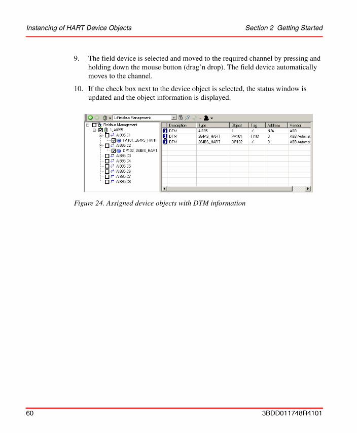
9. The field device is selected and moved to the required channel by pressing and holding down the mouse button (drag’n drop). The field device automatically moves to the channel.
10. If the check box next to the device object is selected, the status window is updated and the object information is displayed.
Figure 24. Assigned device objects with DTM information
60 3BDD011748R4101
Section 2 Getting Started Configuration and commissioning of HART Device Objects
Configuration and commissioning of HART Device Objects
Once the HART Device Objects have been instanced they can be configured for the application via DTM. A configuration describes the creation of a parameter set for a particular device in the database only (in the Aspect Server). To do this, the Fieldbus Management must be switched to Communication disabled mode (see Pre-settings for Instantiation on page 53).
A detailed description of how to start the relevant DTM is given in Starting the Device Type Manager (DTM) on page 65. The configuration of the device via a DTM is described in the associated DTM documentation and is not included in this documentation.
Once the configuration phase is complete for all HART Device Objects, the data records for the relevant device or selection of devices can be
• verified,
• loaded to the device/selection of devices,
• saved in one or more export file(s)
• synchronization of DTM specific data through the 800xA system.
These functions are executed via the Fieldbus Management Aspect and its subconditions. Instance data can be verified and exported with the Fieldbus Management in Communication disabled mode, but loading is only possible in Communication enabled mode. In order to load fieldbus lines, select the line via the context menu of the Fieldbus Management and then click on Download selection to start.
Verify
Selecting the verify option in the Fieldbus Management menu compare the online device date with the inside the 800xA stored offline configuration data set. The result is true, if the data set are equal, otherwise false.
If the verification result is false, an up- or download is recommended for data synchronization.
3BDD011748R4101 61
Configuration and commissioning of HART Device Objects Section 2 Getting Started
Download and Upload
When several devices are selected, the PROFIBUS/HART Fieldbus Builder starts a batch process for up- or download, which is processed sequentially. Execution of the batch process continues even if errors occur in individual DTMs. Each event (faulty/successful execution) is documented in the Fieldbus Management status window. If an error occurs, an error message is displayed after the end of the batch process to indicate that the batch process is faulty.
Export and Import
The export file of an instance data record is saved with a time stamp in a folder which is specific to the Device Object. This makes it possible to build up a device configuration history. Exported device data set can be imported again by selecting the specific export file. The export and import process is carried out manually by the user.
Synchronization of DTM specific data through the 800xA system
DTMs, installed on each client, may store their private internal data in a separate file on the hard disc. This private data could be e.g. log files, last open view, etc. However, “private internal data” does not mean the instance data set of the device parameter. As a default, the DTM stores the private data locally in the shared folder directory on each client.
Synchronization of DTM specific data shall be executed by the user after finishing instancing and configuration of device objects in the Plant Explorers Control Structure.
To synchronize the private DTM data the following steps must be carried out by the user:
Loading errors can arise if this function is not supported by the DTM, e.g. S800 modules, or if the DTM cannot establish a connection to the device.
Further information on the Fieldbus Management Aspect can be found in Fieldbus Management on page 84.
The shared folder directory is described in Industrial IT, 800xA - System, Post Installation Setup 3BUA000156R4101 manual, section “Shared Folder for PROFIBUS and HART Device Integration”.
62 3BDD011748R4101
Section 2 Getting Started Channel Changes on I/O Modules
1. Open Plant Explorer workplace.
2. Switch to the Control Structure.
3. Open the substructure below the Project object.
4. Select a device object below which hold a Fieldbus Management aspect
5. Select the Fieldbus Management aspect.
6. The Fieldbus Management view appears in a window of the Plant Explorer.
7. Select the Fieldbus Management node in the Fieldbus Management tree.
8. Click with the right mouse button to open the context menu.
9. Select Synchronize DTM related path
Channel Changes on I/O Modules
Channel changes can only be made in Communication disabled mode.
The following operations must be carried out to reassign the field devices to the module channels:
1. Open Plant Explorer workplace.
2. Switch to the Control Structure.
3. Open the substructure below the Project object.
4. Select the object below which the device object will be placed, e.g. AI895.
5. Select the Fieldbus Management aspect.
6. Click "+" to open the next level of the partial tree.
7. All positioned field devices, together with the channel information from the parent objects, now appear in the partial tree.
Double-clicking on an Aspect in the Aspect window will open up its contents in a separate process window.
It is recommended to start DTM data synchronization to the end of configuration work to keep network utilization small.
3BDD011748R4101 63

Deleting Device Objects Section 2 Getting Started
8. Select and move the field device to be reassigned to the required channel by pressing and holding down the mouse button (drag’n drop). The field device automatically moves to the channel.
Deleting Device Objects
Deleting device objects can only be made in Communication disabled mode.
The following operations must be carried out to delete the field device from the Control Structure:
1. Open Plant Explorer workplace.
2. Switch to the Control Structure.
3. Open the substructure below the Project object.
4. Select the field device to be deleted in the Control Structure of the Plant Explorer.
5. Click with the right mouse button to open the context menu.
6. Select Delete in the context menu.
Figure 25. Delete device object
64 3BDD011748R4101
Section 2 Getting Started Starting the Device Type Manager (DTM)
Starting the Device Type Manager (DTM)In addition to the Fieldbus Management aspect, every field device features a Device Management aspect. The Device Management aspect opens the associated DTM (Device Definition) in the main window with the instance data record.
DTMs can be started in Communication disabled mode to configure field device objects or, if changes are to be made directly in the device, in Communication enabled mode. Depending on the mode, the DTM will appear with various functional windows. The various modes are selected via the Fieldbus Management aspect of the relevant device object.
Setting objects to Communication disabled/enabled mode is described in Pre-settings for Instantiation on page 53.
Two possibilities are available to open a DTM:
• Via Device Management aspect in the aspect window
• Via Device Functions ... context menu in the Control Structure of the Plant Explorer workplace
Communication enabled mode starts all DTMs required for the communication sequence. Individual DTMs in this connection sequence can not switch to Communication disabled mode without affecting other DTMs started in this sequence.
Certain device-specific DTMs can only be started via the Device Functions context menu. With these DTMs, the Device Management window has a gray background and does not allow graphic interfaces to be displayed.
3BDD011748R4101 65
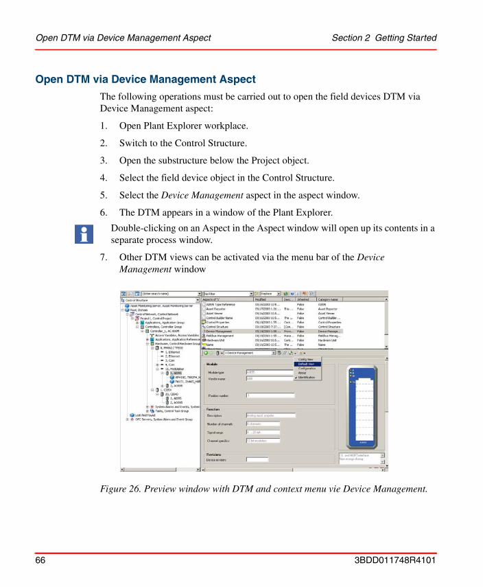
Open DTM via Device Management Aspect Section 2 Getting Started
Open DTM via Device Management Aspect
The following operations must be carried out to open the field devices DTM via Device Management aspect:
1. Open Plant Explorer workplace.
2. Switch to the Control Structure.
3. Open the substructure below the Project object.
4. Select the field device object in the Control Structure.
5. Select the Device Management aspect in the aspect window.
6. The DTM appears in a window of the Plant Explorer.
7. Other DTM views can be activated via the menu bar of the Device Management window
Double-clicking on an Aspect in the Aspect window will open up its contents in a separate process window.
Figure 26. Preview window with DTM and context menu vie Device Management.
66 3BDD011748R4101
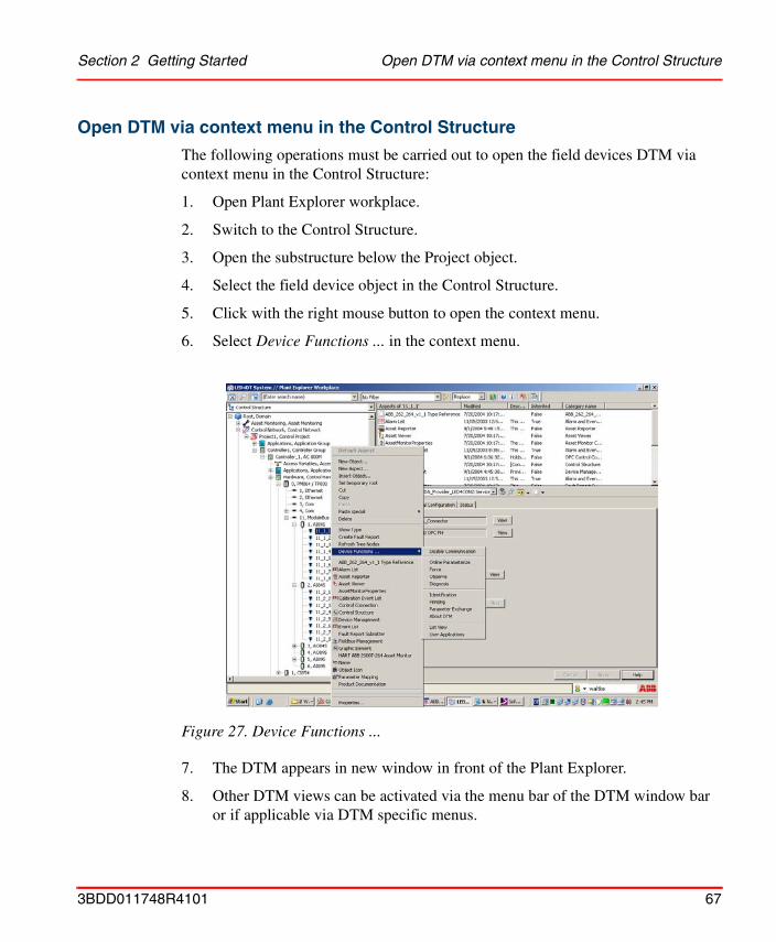
Section 2 Getting Started Open DTM via context menu in the Control Structure
Open DTM via context menu in the Control Structure
The following operations must be carried out to open the field devices DTM via context menu in the Control Structure:
1. Open Plant Explorer workplace.
2. Switch to the Control Structure.
3. Open the substructure below the Project object.
4. Select the field device object in the Control Structure.
5. Click with the right mouse button to open the context menu.
6. Select Device Functions ... in the context menu.
7. The DTM appears in new window in front of the Plant Explorer.
8. Other DTM views can be activated via the menu bar of the DTM window bar or if applicable via DTM specific menus.
Figure 27. Device Functions ...
3BDD011748R4101 67

Starting OPC Server PROFIBUS/HART Section 2 Getting Started
Starting OPC Server PROFIBUS/HARTNewly instanced device objects and changed topologies must be transferred to the OPC Server PROFIBUS/HART.
1. Open Plant Explorer workplace.
2. Switch to the Control Structure.
3. Open the substructure below the Project object.
4. Select a master object (e.g. Modulebus, CI854) in the Control Structure.
5. Select the Fieldbus Management aspect.
6. Select the Fieldbus Management node in the Fieldbus Management tree.
7. Click with the right mouse button to open the context menu.
8. Switch to Communication enabled mode.
9. Select the Fieldbus Management node in the Fieldbus Management tree.
10. Click with the right mouse button on the Fieldbus Management node to open the context menu.
If device objects are only deleted from the existing topology, then the OPC Server does not necessarily need to be configured again. Configuration is only essential if topologies are changed and new device instances are created.
Please read also OPC Server Configuration on page 109, whether special configuration may be required to run the OPC Server properly.
To provide the complete fieldbus architecture of the 800xA system to the OPC Server PH, it is mandatory to switch all CI854 objects and the Modulebus objects to the Communication enabled mode once.
68 3BDD011748R4101
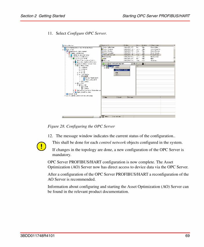
Section 2 Getting Started Starting OPC Server PROFIBUS/HART
11. Select Configure OPC Server.
12. The message window indicates the current status of the configuration..
OPC Server PROFIBUS/HART configuration is now complete. The Asset Optimization (AO) Server now has direct access to device data via the OPC Server.
After a configuration of the OPC Server PROFIBUS/HART a reconfiguration of the AO Server is recommended.
Information about configuring and starting the Asset Optimization (AO) Server can be found in the relevant product documentation.
Figure 28. Configuring the OPC Server
This shall be done for each control network objects configured in the system.
If changes in the topology are done, a new configuration of the OPC Server is mandatory.
3BDD011748R4101 69

Starting OPC Server PROFIBUS/HART Section 2 Getting Started
70 3BDD011748R4101
Section 3 Fieldbus Builder PROFIBUS/HART
OverviewThe Fieldbus Builder PROFIBUS/HART is a component of the HART Device Integration and can only be used in the Industrial IT 800xA system.
The Fieldbus Builder PROFIBUS/HART integrates the FDT/DTM technology in the Industrial IT 800xA system and provides the infrastructure in ABB's Aspect Platform to access field devices, coming with the Device Integration Library of the Device Integration products.
In accordance with the functionality of the DTM, the Fieldbus Builder PROFIBUS/HART accesses field devices for
• Configuration
• Parameterization
• Diagnostics
• Maintenance
• Documentation
The current version of the Fieldbus Builder PROFIBUS/HART supports the FDT 1.2 standard interface.
Device Integration products are available for the HART, PROFIBUS, and FOUNDATION fieldbus protocols. Each product contains a Device Integration Library, which, together with the Fieldbus Builder contained in the product, can be used for field device management.
3BDD011748R4101 71

Section 3 Fieldbus Builder PROFIBUS/HART
The Fieldbus Builder PROFIBUS/HART supports the following functions in the hardware topology of the Plant Explorer Control Structure:
• Selecting a device object starts the corresponding DTM
• The DTM is supplied with instance data from the 800xA system database
• Saving of the current DTM instance data
• Management of the fieldbus topology structure up to the HART field devices
• Configuration and removal of the communication paths for online communication between the DTM and the physical field device in the system
• Configuration of the OPC Server PROFIBUS/HART
• Provision of DTM internal instance data for bulk data applications (if supported by the DTM)
• Support of 800xA System Audit Trail interface
The information following this section provides a general description of the Fieldbus Builder PROFIBUS/HART. Some descriptions about Fieldbus Builder Aspects are only required if you wish to develop your own object types.
ABB cannot guarantee an operable 800xA system if device object types are created/modified manually. Only tested software (DTMs) may be installed on the system computer. All software supplied in the Device Integration meets this requirement.
Additional information about the device library and the integration of new device objects can be found in Section 5, HART Device Integration Library.
72 3BDD011748R4101
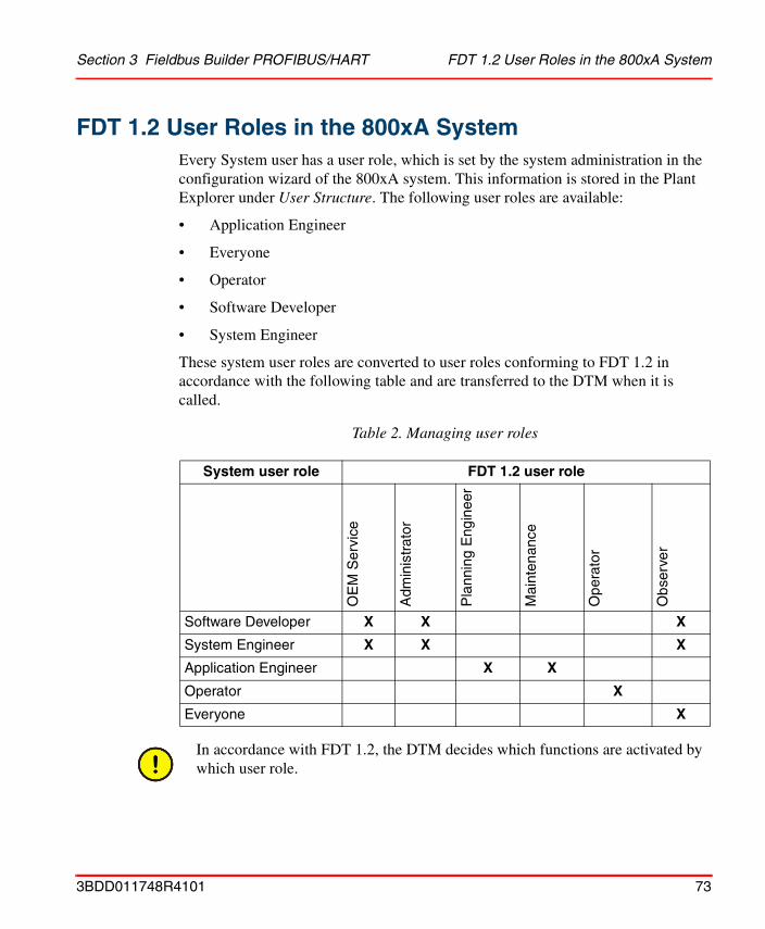
Section 3 Fieldbus Builder PROFIBUS/HART FDT 1.2 User Roles in the 800xA System
FDT 1.2 User Roles in the 800xA SystemEvery System user has a user role, which is set by the system administration in the configuration wizard of the 800xA system. This information is stored in the Plant Explorer under User Structure. The following user roles are available:
• Application Engineer
• Everyone
• Operator
• Software Developer
• System Engineer
These system user roles are converted to user roles conforming to FDT 1.2 in accordance with the following table and are transferred to the DTM when it is called.
Table 2. Managing user roles
System user role FDT 1.2 user role
OE
M S
ervi
ce
Adm
inis
trat
or
Pla
nnin
g E
ngin
eer
Mai
nten
ance
Ope
rato
r
Obs
erve
r
Software Developer X X X
System Engineer X X X
Application Engineer X X
Operator X
Everyone X
In accordance with FDT 1.2, the DTM decides which functions are activated by which user role.
3BDD011748R4101 73

Fieldbus Builder PROFIBUS/HART Aspects Section 3 Fieldbus Builder PROFIBUS/HART
Fieldbus Builder PROFIBUS/HART Aspects
Aspect Overview
Once the Fieldbus Builder PROFIBUS/HART has been installed, it is available as a new aspect system. The aspect system adds the following aspects to the 800xA system:
Table 3. PROFIBUS/HART Fieldbus Builder aspects
Aspect Function
Device Definition This aspect allows an installed DTM to be assigned to a specific object in the Object Type Structure.
Device Management This aspect starts the DTM with its instance data.
Fieldbus Management This aspect opens the graphical user interface of the PROFIBUS/HART Fieldbus Builder.
FBB PH Settings This aspect enables private DTM data synchronization through the system.
Module Definition For DTMs with internal module planning.
This aspect is used to assign a module with a unique ID for the corresponding master DTM and is only visible in the Object Type Structure.
It is required for modular DTMs (module planning takes place within the DTM) in order to identify the modules in the Plant Explorer uniquely, and to position and present them.
Module Management For DTMs with internal module planning.
This aspect is used by the Fieldbus Builder PROFIBUS/HART to save instance-specific data for a module and is only visible in the Object Type Structure.
PROFIBUS Management This aspect allows the access to the AC 800M/CI854 web server for all connected PROFIBUS CI854 modules on this controller.
74 3BDD011748R4101
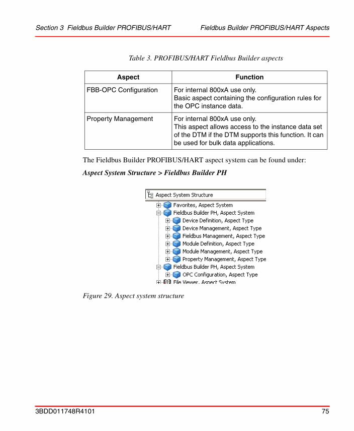
Section 3 Fieldbus Builder PROFIBUS/HART Fieldbus Builder PROFIBUS/HART Aspects
The Fieldbus Builder PROFIBUS/HART aspect system can be found under:
Aspect System Structure > Fieldbus Builder PH
FBB-OPC Configuration For internal 800xA use only.Basic aspect containing the configuration rules for the OPC instance data.
Property Management For internal 800xA use only.This aspect allows access to the instance data set of the DTM if the DTM supports this function. It can be used for bulk data applications.
Figure 29. Aspect system structure
Table 3. PROFIBUS/HART Fieldbus Builder aspects
Aspect Function
3BDD011748R4101 75
Fieldbus Builder PROFIBUS/HART Aspects Section 3 Fieldbus Builder PROFIBUS/HART
As illustrated in Figure 29, the Fieldbus Builder PROFIBUS/HART aspect system is divided into two system entries.
The first system entry contains aspects required for working with device objects and for their configuration.
The second system entry contains an aspect for accessing internal device data via OPC communication. Additional information about OPC can be found in Section 4, OPC Server PROFIBUS/HART
Unless described in more detail, the aspects of the Fieldbus Builder PROFIBUS/HART are configured and may not be modified by the user. ABB Service must be informed before the user makes any changes to the aspects described in this document.
76 3BDD011748R4101
Section 3 Fieldbus Builder PROFIBUS/HART Aspects in the Object Type Structure
Aspects in the Object Type StructureThe Object Type Structure contains the device objects to be used in the projects. The individual device objects are described in the Section 5, HART Device Integration Library.
Objects in the Object Type Structure managed using the Fieldbus Builder PROFIBUS/HART must have the following aspects:
• Device DefinitionThis aspect assigns the DTM to the object
• DIP Fieldbus Builder PH Extension DefinitionThis aspect handles the Fieldbus Builder aspects during instantiation
The aspects described here are configured for the device object types supplied with the device library and do not need any other settings. Unless indicated otherwise, these aspects are designed to be used for developing new object types, which may only be implemented in an 800xA system once they have been approved by ABB. Please contact ABB Service.
3BDD011748R4101 77
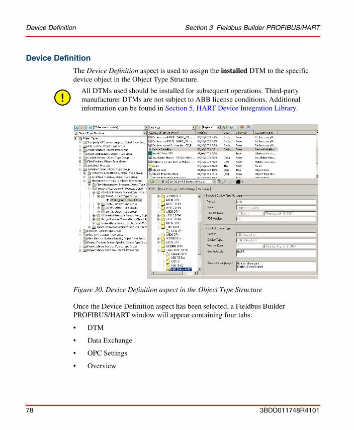
Device Definition Section 3 Fieldbus Builder PROFIBUS/HART
Device Definition
The Device Definition aspect is used to assign the installed DTM to the specific device object in the Object Type Structure.
Once the Device Definition aspect has been selected, a Fieldbus Builder PROFIBUS/HART window will appear containing four tabs:
• DTM
• Data Exchange
• OPC Settings
• Overview
Figure 30. Device Definition aspect in the Object Type Structure
All DTMs used should be installed for subsequent operations. Third-party manufacturer DTMs are not subject to ABB license conditions. Additional information can be found in Section 5, HART Device Integration Library.
78 3BDD011748R4101
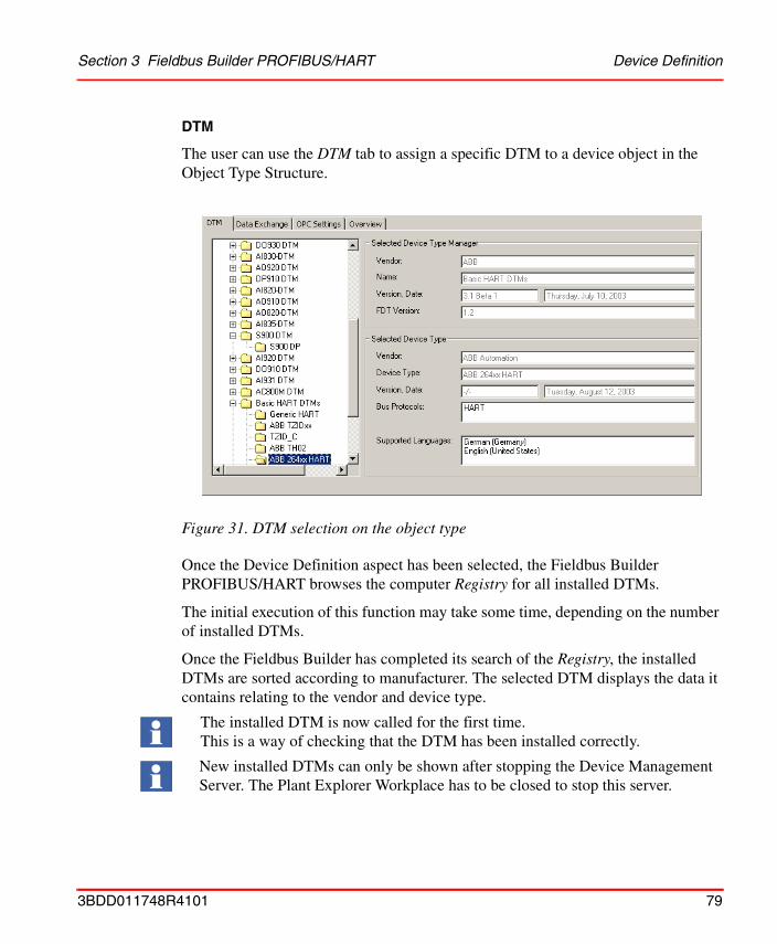
Section 3 Fieldbus Builder PROFIBUS/HART Device Definition
DTM
The user can use the DTM tab to assign a specific DTM to a device object in the Object Type Structure.
Once the Device Definition aspect has been selected, the Fieldbus Builder PROFIBUS/HART browses the computer Registry for all installed DTMs.
The initial execution of this function may take some time, depending on the number of installed DTMs.
Once the Fieldbus Builder has completed its search of the Registry, the installed DTMs are sorted according to manufacturer. The selected DTM displays the data it contains relating to the vendor and device type.
Figure 31. DTM selection on the object type
The installed DTM is now called for the first time.This is a way of checking that the DTM has been installed correctly.
New installed DTMs can only be shown after stopping the Device Management Server. The Plant Explorer Workplace has to be closed to stop this server.
3BDD011748R4101 79
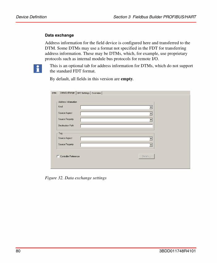
Device Definition Section 3 Fieldbus Builder PROFIBUS/HART
Data exchange
Address information for the field device is configured here and transferred to the DTM. Some DTMs may use a format not specified in the FDT for transferring address information. These may be DTMs, which, for example, use proprietary protocols such as internal module bus protocols for remote I/O.
Figure 32. Data exchange settings
This is an optional tab for address information for DTMs, which do not support the standard FDT format.
By default, all fields in this version are empty.
80 3BDD011748R4101

Section 3 Fieldbus Builder PROFIBUS/HART Device Definition
OPC Settings
The user can use the OPC Settings tab for an additional assignment of an OPC DTM to a field device object in order to make device data available to higher-level applications via OPC access. For this purpose, an OPC-compatible DTM is selected from the proposed DTM list.
See Section 4, OPC Server PROFIBUS/HART for detailed information.
Figure 33. OPC access settings
3BDD011748R4101 81
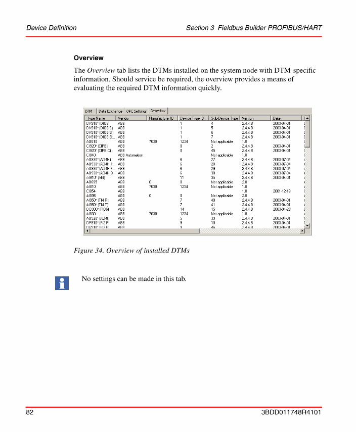
Device Definition Section 3 Fieldbus Builder PROFIBUS/HART
Overview
The Overview tab lists the DTMs installed on the system node with DTM-specific information. Should service be required, the overview provides a means of evaluating the required DTM information quickly.
Figure 34. Overview of installed DTMs
No settings can be made in this tab.
82 3BDD011748R4101
Section 3 Fieldbus Builder PROFIBUS/HART DIP Fieldbus Builder PH Extension Definition
DIP Fieldbus Builder PH Extension Definition
The DIP Fieldbus Builder PH Extension Definition aspect is linked to field device objects in the Object Type Structure when the "Device Integration Library" system extension is loaded.
The aspect contains instantiation rules for the device object, which are tested by the Fieldbus Builder PROFIBUS/HART when the type is inserted in the Control Structure.
This aspect does not require any further configuration by the user.
3BDD011748R4101 83
Aspects in the Control Structure Section 3 Fieldbus Builder PROFIBUS/HART
Aspects in the Control Structure
Fieldbus Builder PROFIBUS/HART user interface
The main user interface for the Fieldbus Builder PROFIBUS/HART is the Control Structure of the Plant Explorer. Within the Control Structure, the Fieldbus Builder PROFIBUS/HART is controlled by means of the following aspects:
• Fieldbus Management
• Device Management
All plans for field devices (including eventual startup) are to be made in the Control Structure of the Plant Explorer with the Fieldbus Management aspect. The PROFIBUS/HART Fieldbus Builder works exclusively in conjunction with this structure.
Fieldbus Management
This aspect is used to open the graphical user interface of the Fieldbus Builder PROFIBUS/HART in the window.
Fieldbus Management is to be used:
• To assign HART field devices to input/output module channels with HART functionality
• To manage the Communication disabled and Communication enabled operating modes
• To read and load the field device data of objects by means of their DTMs
• To synchronize DTM data between all related 800xA Connectivity Server.
• To configure the OPC Server PROFIBUS/HART
• To import and export DTM device instance data
84 3BDD011748R4101
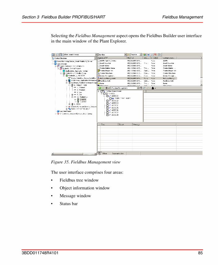
Section 3 Fieldbus Builder PROFIBUS/HART Fieldbus Management
Selecting the Fieldbus Management aspect opens the Fieldbus Builder user interface in the main window of the Plant Explorer.
The user interface comprises four areas:
• Fieldbus tree window
• Object information window
• Message window
• Status bar
Figure 35. Fieldbus Management view
3BDD011748R4101 85
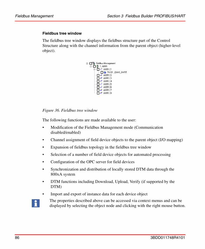
Fieldbus Management Section 3 Fieldbus Builder PROFIBUS/HART
Fieldbus tree window
The fieldbus tree window displays the fieldbus structure part of the Control Structure along with the channel information from the parent object (higher-level object).
The following functions are made available to the user:
• Modification of the Fieldbus Management mode (Communication disabled/enabled)
• Channel assignment of field device objects to the parent object (I/O mapping)
• Expansion of fieldbus topology in the fieldbus tree window
• Selection of a number of field device objects for automated processing
• Configuration of the OPC server for field devices
• Synchronization and distribution of locally stored DTM data through the 800xA system
• DTM functions including Download, Upload, Verify (if supported by the DTM)
• Import and export of instance data for each device object
Figure 36. Fieldbus tree window
The properties described above can be accessed via context menus and can be displayed by selecting the object node and clicking with the right mouse button.
86 3BDD011748R4101
Section 3 Fieldbus Builder PROFIBUS/HART Fieldbus Management
Context menu in the fieldbus tree
Depending on the object node selected, the user is offered various context menus. The fieldbus tree differentiates between 3 types of node:
• Fieldbus Management nodeThis is always the master node in the fieldbus tree window.
• Channel objectsInstead of displaying address information, channel objects are identified by an icon representing two arrows pointing in opposite directions.
• Device objectsDevice objects in the fieldbus tree always display a device address in the form of an integer number or a tag name.
Context menu entries are activated/deactivated on the basis of the user role as well as the communication mode (Communication disabled/enabled).
3BDD011748R4101 87
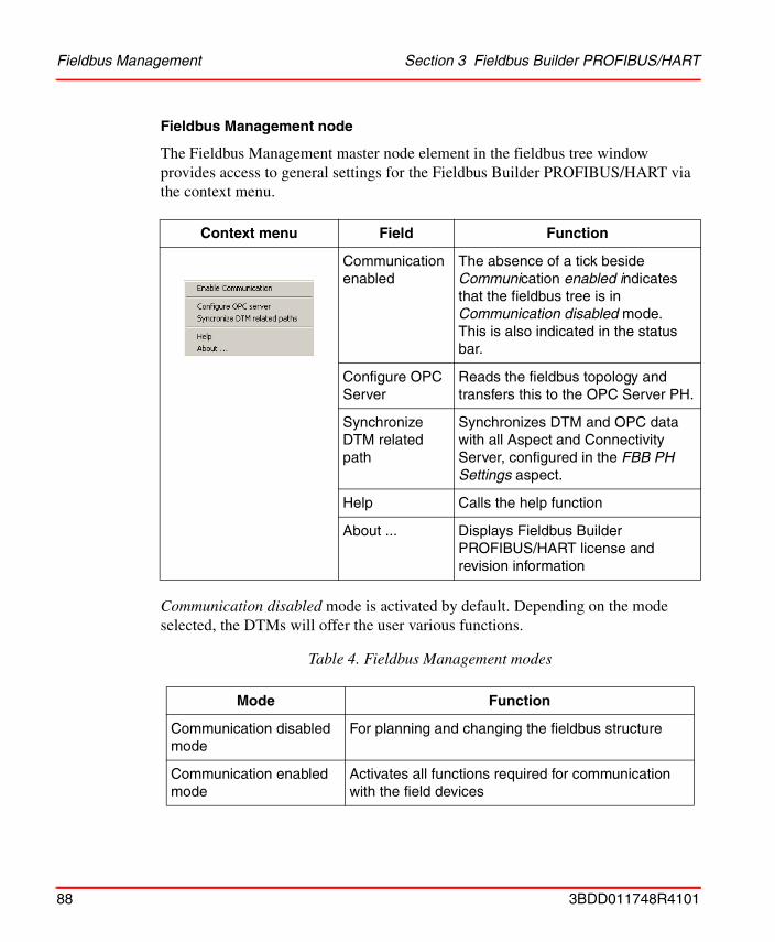
Fieldbus Management Section 3 Fieldbus Builder PROFIBUS/HART
Fieldbus Management node
The Fieldbus Management master node element in the fieldbus tree window provides access to general settings for the Fieldbus Builder PROFIBUS/HART via the context menu.
Communication disabled mode is activated by default. Depending on the mode selected, the DTMs will offer the user various functions.
Context menu Field Function
Communication enabled
The absence of a tick beside Communication enabled indicates that the fieldbus tree is in Communication disabled mode.This is also indicated in the status bar.
Configure OPC Server
Reads the fieldbus topology and transfers this to the OPC Server PH.
Synchronize DTM related path
Synchronizes DTM and OPC data with all Aspect and Connectivity Server, configured in the FBB PH Settings aspect.
Help Calls the help function
About ... Displays Fieldbus Builder PROFIBUS/HART license and revision information
Table 4. Fieldbus Management modes
Mode Function
Communication disabled mode
For planning and changing the fieldbus structure
Communication enabled mode
Activates all functions required for communication with the field devices
88 3BDD011748R4101
Section 3 Fieldbus Builder PROFIBUS/HART Fieldbus Management
The selected mode applies to the entire fieldbus line, as far as the master nodes.
Changing from Communication enabled to disabled mode may take some time if communication with field devices is still active. The disconnection of the data path is indicated by a progress bar in the status bar.
If the tree is active in Communication enabled mode, the user may not modify the fieldbus topology. This means that no new devices can be integrated into the active topology and no address modifications can be made directly on the object.
3BDD011748R4101 89

Fieldbus Management Section 3 Fieldbus Builder PROFIBUS/HART
Channel object
Channel object mode enables the user to display lower-level fieldbus structures quickly and to select device objects on the same layout level. Selected device objects are processed via the operational routine of the Fieldbus Builder PROFIBUS/HART, i.e. the DTM parameter set is loaded from the device to the instance data set or written from the data set to the device (upload/download) as long as the DTM supports this function. Channel objects are identified by an icon representing two arrows pointing in opposite directions.
Context menu Field Function
Expand Expands the topology tree below the channel object node.
Select Line This function can be used to select all device objects on the same level.
Upload Line This function calls the selected DTMs without GUI, reads the current data from the fieldbus devices, and uses this as the new instance data.The function is only available in Communication enabled mode.
Download Line This function calls the selected DTMs without GUI and downloads the instance data to the fieldbus devices.The function is only available in Communication enabled mode.
90 3BDD011748R4101
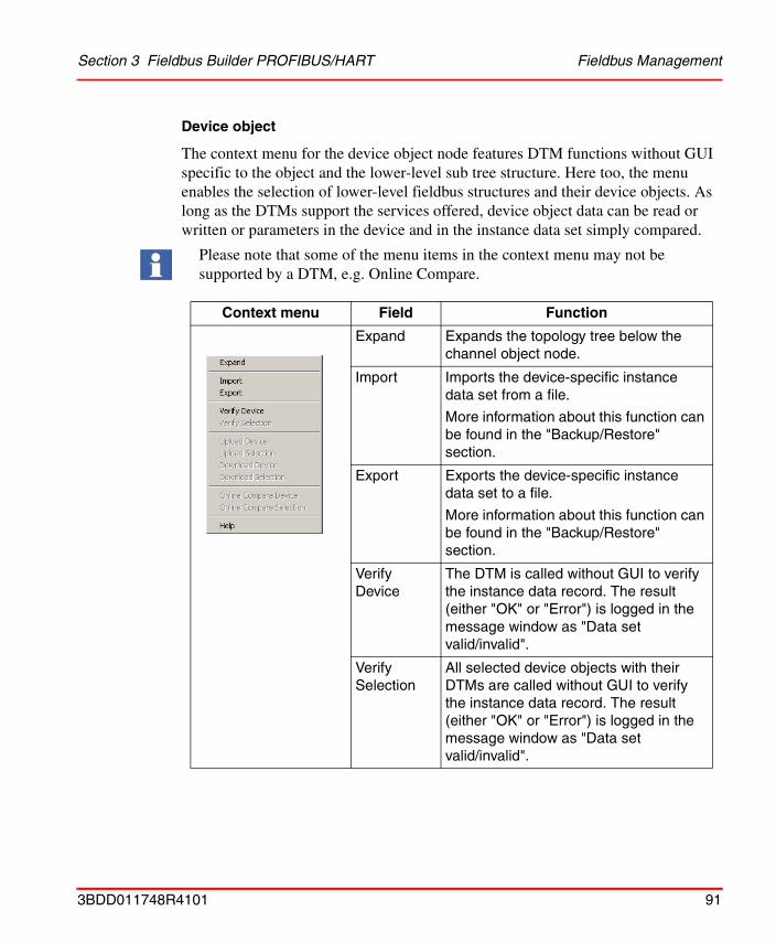
Section 3 Fieldbus Builder PROFIBUS/HART Fieldbus Management
Device object
The context menu for the device object node features DTM functions without GUI specific to the object and the lower-level sub tree structure. Here too, the menu enables the selection of lower-level fieldbus structures and their device objects. As long as the DTMs support the services offered, device object data can be read or written or parameters in the device and in the instance data set simply compared.
Please note that some of the menu items in the context menu may not be supported by a DTM, e.g. Online Compare.
Context menu Field Function
Expand Expands the topology tree below the channel object node.
Import Imports the device-specific instance data set from a file.
More information about this function can be found in the "Backup/Restore" section.
Export Exports the device-specific instance data set to a file.
More information about this function can be found in the "Backup/Restore" section.
Verify Device
The DTM is called without GUI to verify the instance data record. The result (either "OK" or "Error") is logged in the message window as "Data set valid/invalid".
Verify Selection
All selected device objects with their DTMs are called without GUI to verify the instance data record. The result (either "OK" or "Error") is logged in the message window as "Data set valid/invalid".
3BDD011748R4101 91
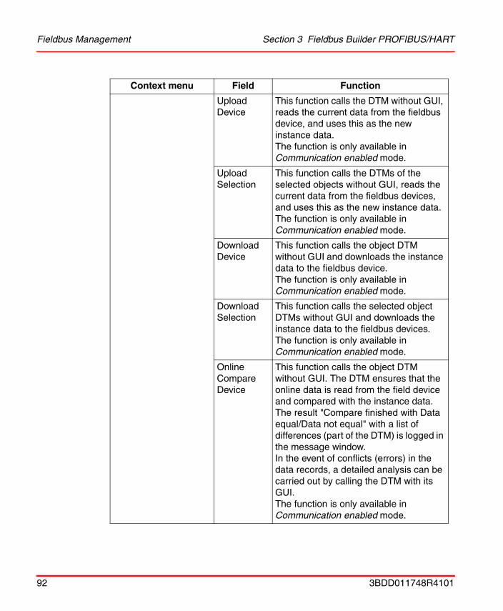
Fieldbus Management Section 3 Fieldbus Builder PROFIBUS/HART
Upload Device
This function calls the DTM without GUI, reads the current data from the fieldbus device, and uses this as the new instance data.The function is only available in Communication enabled mode.
Upload Selection
This function calls the DTMs of the selected objects without GUI, reads the current data from the fieldbus devices, and uses this as the new instance data.The function is only available in Communication enabled mode.
Download Device
This function calls the object DTM without GUI and downloads the instance data to the fieldbus device.The function is only available in Communication enabled mode.
Download Selection
This function calls the selected object DTMs without GUI and downloads the instance data to the fieldbus devices.The function is only available in Communication enabled mode.
Online Compare Device
This function calls the object DTM without GUI. The DTM ensures that the online data is read from the field device and compared with the instance data.The result "Compare finished with Data equal/Data not equal" with a list of differences (part of the DTM) is logged in the message window.In the event of conflicts (errors) in the data records, a detailed analysis can be carried out by calling the DTM with its GUI.The function is only available in Communication enabled mode.
Context menu Field Function
92 3BDD011748R4101
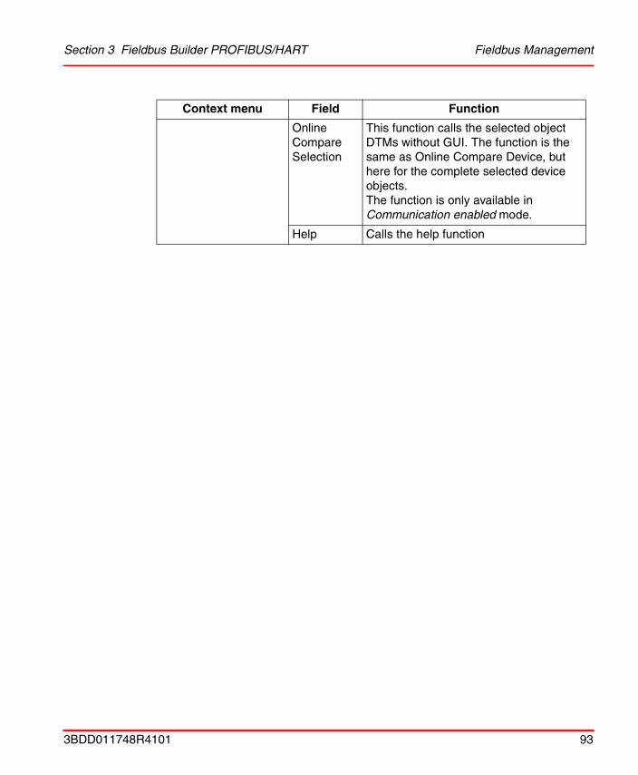
Section 3 Fieldbus Builder PROFIBUS/HART Fieldbus Management
Online Compare Selection
This function calls the selected object DTMs without GUI. The function is the same as Online Compare Device, but here for the complete selected device objects.The function is only available in Communication enabled mode.
Help Calls the help function
Context menu Field Function
3BDD011748R4101 93
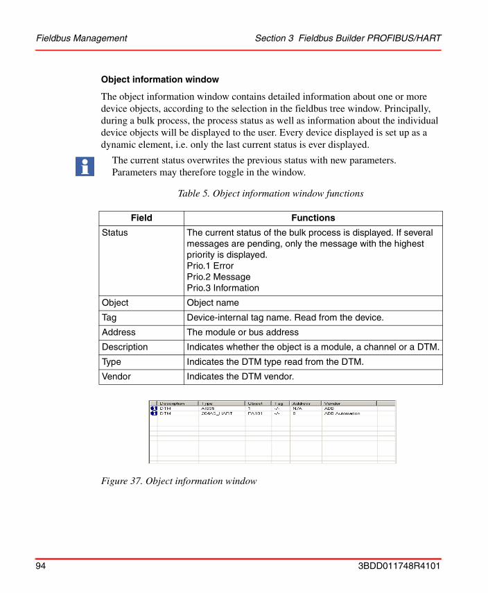
Fieldbus Management Section 3 Fieldbus Builder PROFIBUS/HART
Object information window
The object information window contains detailed information about one or more device objects, according to the selection in the fieldbus tree window. Principally, during a bulk process, the process status as well as information about the individual device objects will be displayed to the user. Every device displayed is set up as a dynamic element, i.e. only the last current status is ever displayed.
The current status overwrites the previous status with new parameters. Parameters may therefore toggle in the window.
Figure 37. Object information window
Table 5. Object information window functions
Field Functions
Status The current status of the bulk process is displayed. If several messages are pending, only the message with the highest priority is displayed.Prio.1 ErrorPrio.2 MessagePrio.3 Information
Object Object name
Tag Device-internal tag name. Read from the device.
Address The module or bus address
Description Indicates whether the object is a module, a channel or a DTM.
Type Indicates the DTM type read from the DTM.
Vendor Indicates the DTM vendor.
94 3BDD011748R4101

Section 3 Fieldbus Builder PROFIBUS/HART Fieldbus Management
Message window
The message window indicates the current status of actions executed, which were defined in the fieldbus tree.
Figure 38. Message window
Table 6. Message window functions
Field Functions
Empty The error, message or information icon appears here.
Time The date and time for the result is entered.
Object Object name
Message Message text for the result
Select a field to sort the entries. Select the same field again to invert the sort.
3BDD011748R4101 95

Fieldbus Management Section 3 Fieldbus Builder PROFIBUS/HART
Status bar
The status bar indicates the current Fieldbus Management mode (Communication disabled/enabled) as well as the time characteristic of any DTM actions executed.
Table 7. Fieldbus Management status bar
Field Functions
Icon, mode The current mode (Communication disabled or enabled) appears here.
Progress bar Progress bars appear for functions requiring lengthy execution times. This progress bar does not indicate the execution progress. It only indicates that a function is being executed.Why? For example, the PROFIBUS/HART Fieldbus Builder starts the appropriate DTM for downloading an instance data record to a HART field device. The DTM itself downloads the data and only the DTM knows the current status of the download process.The DTM only notifies the Fieldbus Builder PROFIBUS/HART at the end of the process if the download was successful or was terminated with errors. This is logged in the message window.
96 3BDD011748R4101
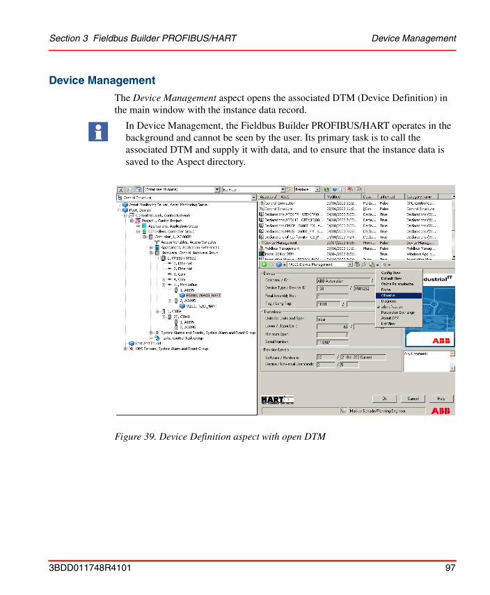
Section 3 Fieldbus Builder PROFIBUS/HART Device Management
Device Management
The Device Management aspect opens the associated DTM (Device Definition) in the main window with the instance data record.
In Device Management, the Fieldbus Builder PROFIBUS/HART operates in the background and cannot be seen by the user. Its primary task is to call the associated DTM and supply it with data, and to ensure that the instance data is saved to the Aspect directory.
Figure 39. Device Definition aspect with open DTM
3BDD011748R4101 97
Device Management Section 3 Fieldbus Builder PROFIBUS/HART
DTMs can be started in Communication disabled mode to configure field device objects or, if changes are to be made directly in the device, in Communication enabled mode. Depending on the mode, the DTM will appear with various functional windows. The various modes are selected via the Fieldbus Management aspect of the relevant device object.
Setting this object to Communication disabled/enabled mode is described in Pre-settings for Instantiation on page 53 in this document.
The following operations must be carried out to open the field devices DTM:
1. Select the field device object in the Control Structure.
2. Two possibilities are available to open a DTM:
– Select the Device Management aspect in the aspect window.
– Click at the device object in the Control Structure with the right mouse button to open the context menu. Select Device Functions in the context menu.
3. The DTM appears in the main window of the Plant Explorer by using the Device Management Aspect or in its own window by using the Device Functions context menu.
4. Other DTM views can be activated via the menu bar of the Device Management window (DTM-specific) or via Device Functions context menu.
Communication enabled mode starts all DTMs required for the communication sequence. Individual DTMs in this connection sequence can then not switch to Communication disabled mode without affecting other DTMs started in this sequence.
98 3BDD011748R4101
Section 4 OPC Server PROFIBUS/HART
OverviewOPC is an abbreviation for OLE for Process Control. OLE for Process Control is an open interface standard, which is based on the OLE (Object Linking and Embedding) Windows-based technology, COM (Component Object Model) and DCOM (Distributed Component Object Model), and enables simple, standardized data exchanged between applications in industrial environments and both the office world and the world of production and manufacturing.
The OPC Server PROFIBUS/HART provides data from PROFIBUS and HART fieldbus devices to the Asset Optimizer Server. This means that 800xA Asset Optimization can access connected field device data. In connection with Asset Monitors, the OPC Server PROFIBUS/HART is used to access specific field device data, device status, and diagnostic data to make necessary informed maintenance decisions.
• Every value acquired via OPC has a time stamp and a status.
• OPC allows Asset Optimization applications to specify required scan rates (depends on the speed of the data communication through the 800xA system).
• An OPC client can be used to monitor and select variables on a server.
• The concept of creating groups permits a variety of sets of variables with different scan rates.
The interfaces feature all the functions designated as "required" in the OPC specifications. The browser interface was also added. An external client can use these functions to read out the list of variables known to an OPC Server PROFIBUS/HART.
The OPC specification describes different methods for accessing and distributing data between OPC clients and servers.
3BDD011748R4101 99
Abbreviations used Section 4 OPC Server PROFIBUS/HART
The OPC Server PROFIBUS/HART is purely a data access server, as HART does not support e.g. alarms and events. PROFIBUS alarms and events are part of the cyclic communication layer and are therefore evaluated by the AC 800M controller OPC Server.
Abbreviations used
Due to the nature of the HART protocol and the necessary routing through the system, update rate for HART data may reads several 10 seconds. Limitations are described in Resources, maximum values and performance on page 102.
Table 8. List of abbreviations
Term Explanation
OPC OPC stands for "OLE for Process Control" and is based on the Microsoft OLE core technologies COM and DCOM.
COM In order to make objects implemented on different platforms or computer architectures compatible, a specification must be drawn up to determine how these platforms interpret an object. It is for this purpose that COM (Component Object Model) was defined. COM defines a standard for the exchange of data and functions, which enables communication between objects and applications regardless of connection protocols and programming languages.
DCOM The object model for cross-computer calls is called DCOM (Distributed COM). DCOM is part of the Windows operating system.
FBB PH Fieldbus Builder PROFIBUS/HART
The Fieldbus Builder PROFIBUS/HART aspect system can be used to integrate PROFIBUS and HART field devices into the Industrial IT 800xA system using FDT/DTM technology.
100 3BDD011748R4101
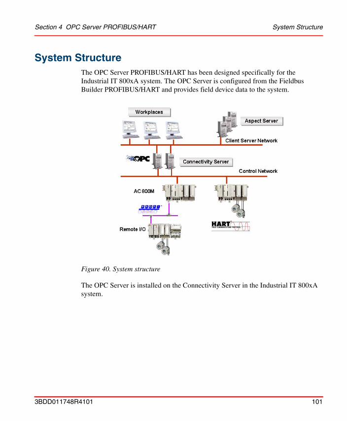
Section 4 OPC Server PROFIBUS/HART System Structure
System StructureThe OPC Server PROFIBUS/HART has been designed specifically for the Industrial IT 800xA system. The OPC Server is configured from the Fieldbus Builder PROFIBUS/HART and provides field device data to the system.
The OPC Server is installed on the Connectivity Server in the Industrial IT 800xA system.
Figure 40. System structure
3BDD011748R4101 101
Resources, maximum values and performance Section 4 OPC Server PROFIBUS/HART
Resources, maximum values and performance
Hardware limitation
Number of PROFIBUS/HART OPC Servers in an 800xA project:
• 1 per control network or sub-component such as a controller or module bus object on a single Connectivity Server
Number of workstations with OPC clients:
• See 800xA system workstation restrictions
Number of field device objects per OPC SERVER PROFIBUS/HART
• See HART Device Integration release notes
Communication
Released application for OPC server PH:
• See HART Device Integration release notes
Update rate for OPC server: Default = 60000 ms (Control Connection Aspect)
The update rate should be configured in accordance with the OPC client, i.e. Asset Monitors. The asset monitors linked to the device objects which come with the Device Integration are preconfigured in its update rate.
Please note that the update rate needs to be adapted for the application according to the number of devices in the system.
Requests from OPC clients for OPC items with simultaneous access from the OPC Server PH are worked through in sequence. Depending on bus usage, the configured update rate may not be attained, in which case the OPC Server will return the last valid value. The new value will then be accessible during the next access to the OPC item.
The update rate should be set to a value which keeps bus usage low and does not adversely affect the performance of the system. Real time values cannot be achieved for parallel OPC requests from the client, as these requests are worked through in sequence.
102 3BDD011748R4101
Section 4 OPC Server PROFIBUS/HART OPC Server PROFIBUS/HART Aspect
OPC Server PROFIBUS/HART AspectSome Fieldbus Builder PROFIBUS/HART aspects are required for the configuration/operation of this OPC Server.
Aspect overview
The following aspects are required for the operation of the OPC Server PH:
Of the aspects that are valid both for the Fieldbus Builder PH and for the OPC Server PH, only those relevant to OPC will be discussed in this section.
Unless described in more detail, settings for the aspects described here may be modified by ABB Service.
Table 9. OPC Server PROFIBUS/HART aspects
Aspect Function
Device Definition This aspect can be used to assign an installed OPC DTM to a specific object in the Object Type Structure.
Fieldbus Management This aspect contains the "Configure OPC Server" menu item, which initiates the transfer of the fieldbus topology to the OPC Server.
FBB PH Settings This aspect enables OPC data synchronization through the system.
Control Connection Displays the OPC items available for a certain field device.
FBB-OPC Data Source Definition
Configures the OPC connectivity to a certain Fieldbus OPC Server. The OPC Server is normally located on a Connectivity Server of the 800xA System.
Redundant Connectivity Server are also configured via this aspect.
FBB-OPC Configuration Base aspect containing the configuration data for the OPC Server.
3BDD011748R4101 103
Aspects in the Object Type Structure Section 4 OPC Server PROFIBUS/HART
Each of the aspects listed above is installed in the required position when the Device Integration is installed, i.e. some aspects are generated on object types during system instantiation. Some aspects have already been described in Section 3, Fieldbus Builder PROFIBUS/HART and are therefore only mentioned briefly here.
Aspects in the Object Type StructureThe Object Type Structure contains aspects used for OPC communication on instantiated device objects.
In order to establish an OPC connection with a field device, a specific DTM, which supplies data to the OPC Server, must be integrated on the device object. The Basic HART DTM, which is installed with the Device Integration, can for example set up this OPC access. Device object types installed with the Device Integration device library, always contain the associated OPC DTM.
The following aspects must be available on the device object type for OPC access:
• Device DefinitionThis aspect assigns an OPC DTM to the device object.
104 3BDD011748R4101
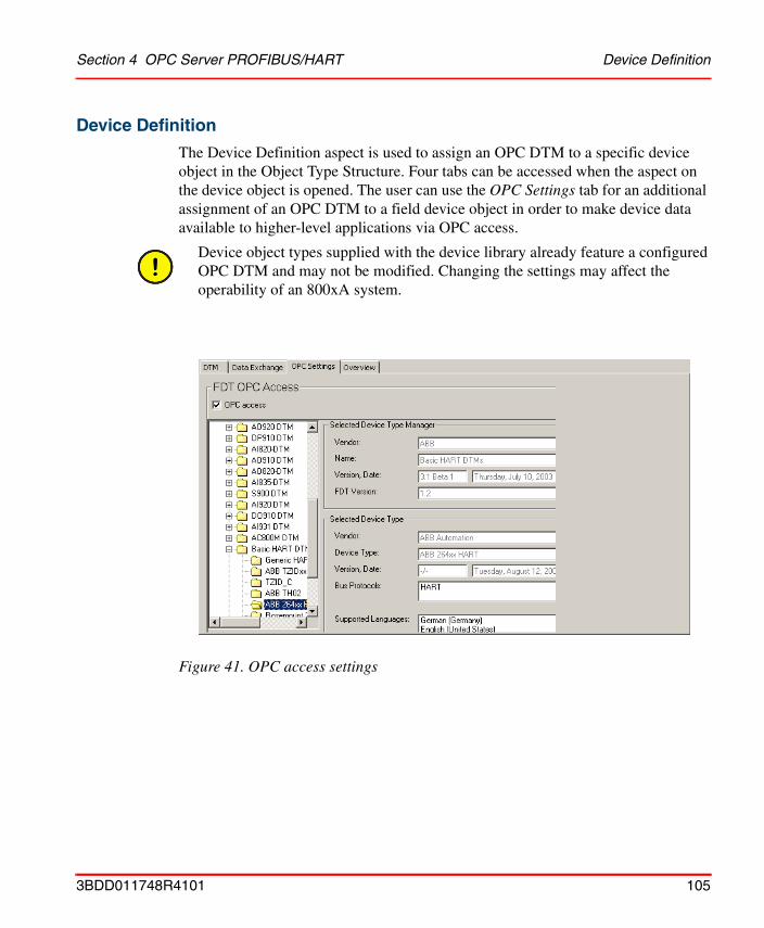
Section 4 OPC Server PROFIBUS/HART Device Definition
Device Definition
The Device Definition aspect is used to assign an OPC DTM to a specific device object in the Object Type Structure. Four tabs can be accessed when the aspect on the device object is opened. The user can use the OPC Settings tab for an additional assignment of an OPC DTM to a field device object in order to make device data available to higher-level applications via OPC access.
Device object types supplied with the device library already feature a configured OPC DTM and may not be modified. Changing the settings may affect the operability of an 800xA system.
Figure 41. OPC access settings
3BDD011748R4101 105
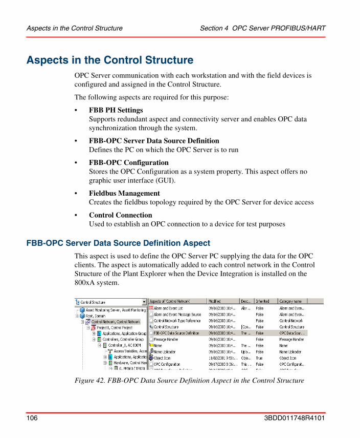
Aspects in the Control Structure Section 4 OPC Server PROFIBUS/HART
Aspects in the Control StructureOPC Server communication with each workstation and with the field devices is configured and assigned in the Control Structure.
The following aspects are required for this purpose:
• FBB PH SettingsSupports redundant aspect and connectivity server and enables OPC data synchronization through the system.
• FBB-OPC Server Data Source DefinitionDefines the PC on which the OPC Server is to run
• FBB-OPC ConfigurationStores the OPC Configuration as a system property. This aspect offers no graphic user interface (GUI).
• Fieldbus ManagementCreates the fieldbus topology required by the OPC Server for device access
• Control ConnectionUsed to establish an OPC connection to a device for test purposes
FBB-OPC Server Data Source Definition Aspect
This aspect is used to define the OPC Server PC supplying the data for the OPC clients. The aspect is automatically added to each control network in the Control Structure of the Plant Explorer when the Device Integration is installed on the 800xA system.
Figure 42. FBB-OPC Data Source Definition Aspect in the Control Structure
106 3BDD011748R4101
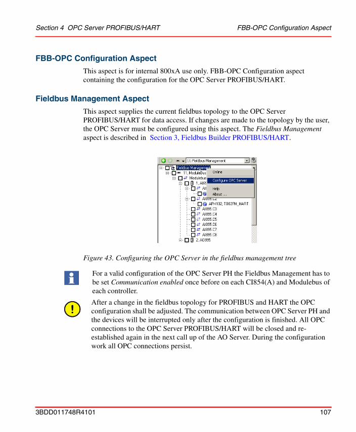
Section 4 OPC Server PROFIBUS/HART FBB-OPC Configuration Aspect
FBB-OPC Configuration Aspect
This aspect is for internal 800xA use only. FBB-OPC Configuration aspect containing the configuration for the OPC Server PROFIBUS/HART.
Fieldbus Management Aspect
This aspect supplies the current fieldbus topology to the OPC Server PROFIBUS/HART for data access. If changes are made to the topology by the user, the OPC Server must be configured using this aspect. The Fieldbus Management aspect is described in Section 3, Fieldbus Builder PROFIBUS/HART.
Figure 43. Configuring the OPC Server in the fieldbus management tree
For a valid configuration of the OPC Server PH the Fieldbus Management has to be set Communication enabled once before on each CI854(A) and Modulebus of each controller.
After a change in the fieldbus topology for PROFIBUS and HART the OPC configuration shall be adjusted. The communication between OPC Server PH and the devices will be interrupted only after the configuration is finished. All OPC connections to the OPC Server PROFIBUS/HART will be closed and re-established again in the next call up of the AO Server. During the configuration work all OPC connections persist.
3BDD011748R4101 107
Control Connection Aspect Section 4 OPC Server PROFIBUS/HART
Control Connection Aspect
The Control Connection aspect indicates the OPC items configured for the device currently selected. Control Connection can be used to test the OPC connection as the OPC items feature a quality status.
The following statuses are possible:
• GoodThere are no problems on the connection, the measured values are being updated at the update rate.
• BadThe OPC Client is not receiving any data from the OPC Server. An online connection to the device is not possible or the configured update rate is to low.
• UncertainThe OPC data is not available in the configured update rate, the last OPC value read is displayed.If the connection is not re-established, the status will switch to Bad.
108 3BDD011748R4101
Section 4 OPC Server PROFIBUS/HART OPC Server Configuration
OPC Server ConfigurationIn order to make the data from a field device available to other system applications, an OPC Server for field devices must be configured in the 800xA project. An OPC Server PROFIBUS/HART resource is entered and subsequently configured in the Control Structure of Plant Explorer.
Pre-settings
The OPC Server software (included in the Device Integration) must be installed on every Connectivity Server of the 800xA system. This software communicates with the 800xA system workstations on which the HART Device Integration is installed and supplies the data 'to the outside' via the OPC interface.
The following procedure must be applied for the correct configuration of the OPC Server.
1. Device Integration installed on every system computer.
2. Control Network is created with AC 800M Controller.
3. OPC Server is assigned to a Connectivity Server in the system.
4. FBB PH Settings aspect is configured.
5. Tool Routing enabled.
6. Fieldbus topology created.
Configuration
Asset Optimization Server settings
Because of the duration of synchronous read operation for the OPC Server PROFIBUS/HART the following registry entries should be configured on the Asset Optimization Server using the Windows system tool RegEdit.
1. Click Windows Start button and select Run
2. Enter regedit in the configuration window and click OK.
3. The Registry Editor dialog opens. The settings are stored in the following folder structure:
3BDD011748R4101 109
Configuration Section 4 OPC Server PROFIBUS/HART
– HKEY_LOCAL_MACHINE\SOFTWARE\ABB\AFW\SystemModules\OPCToolkit\1.0-0\private\OPCHandler
4. Double click at AddItem_Timeout and set the value data to 1200 seconds (20 minutes)
5. Double click at Synch_RW_Timeout and set the value data to 120 seconds (2 minutes)
6. Close Registry Editor.
PROFIBUS/HART OPC Server settings
The PROFIBUS/HART OPC Server turn around time depends on the number of devices, the CPU load of the controllers, and the communication load between Connectivity Server and controllers.
By rule of thumb: 1800000 ms = 0.5 h for up to 200 devices,7200000 ms = 2 h for 201 - 500 devices9000000 ms = 2.5 h for 501 - 800 devices10800000 ms = 3 h for 801 - 1000 devices.
The OPC Server update rate can be configured in the DIP HART Asset Monitor Data Source aspect of the Asset Optimization object.
1. Open Plant Explorers Control Structure
2. Expand the tree structure below the root node
3. Select the Asset Optimization node
4. Select in the Aspect Window the DIP HART Asset Monitor Data Source aspect
110 3BDD011748R4101

Section 4 OPC Server PROFIBUS/HART Configuration
5. Configure OPC Group Update Rate in the displayed table according to the rule described above.
PROFIBUS/HART OPC Server configuration (standard)
The OPC Server PROFIBUS/HART is configured via the "Fieldbus Management" aspect of the Fieldbus Builder PROFIBUS/HART (see Starting OPC Server PROFIBUS/HART on page 68)..
Figure 44. OPC Update Rate
To provide the complete fieldbus architecture of the 800xA system to the OPC Server PH, it is mandatory to switch all CI854 objects and the Modulebus objects to the Communication enabled mode once.
Configuration of the OPC Server PROFIBUS/HART shall be done for each control network object configured in the system.
3BDD011748R4101 111
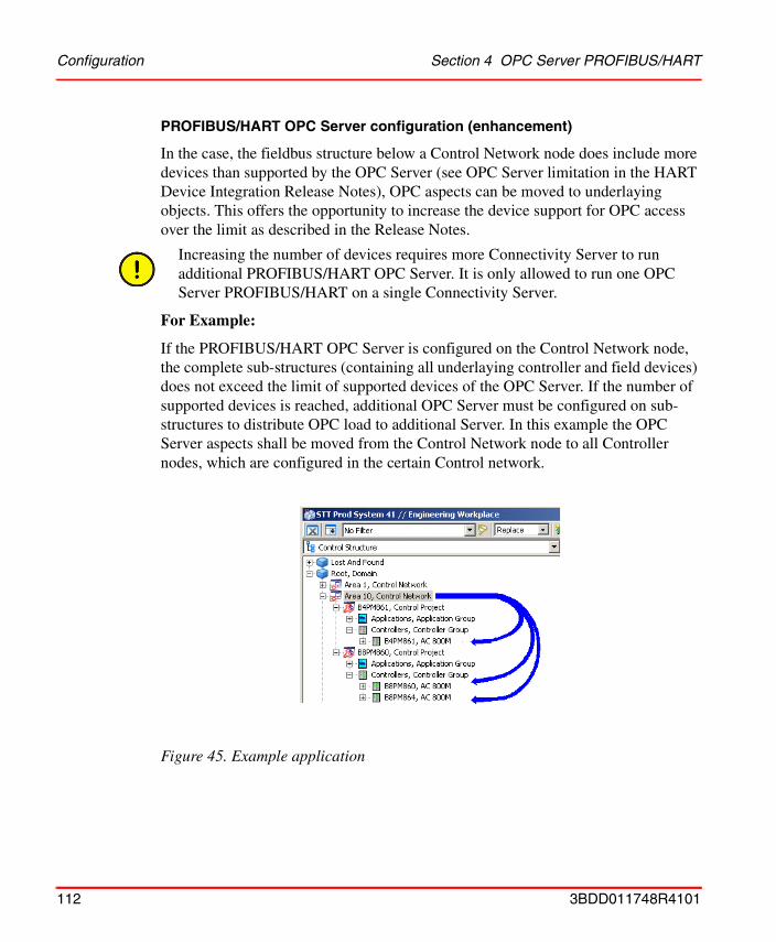
Configuration Section 4 OPC Server PROFIBUS/HART
PROFIBUS/HART OPC Server configuration (enhancement)
In the case, the fieldbus structure below a Control Network node does include more devices than supported by the OPC Server (see OPC Server limitation in the HART Device Integration Release Notes), OPC aspects can be moved to underlaying objects. This offers the opportunity to increase the device support for OPC access over the limit as described in the Release Notes.
For Example:
If the PROFIBUS/HART OPC Server is configured on the Control Network node, the complete sub-structures (containing all underlaying controller and field devices) does not exceed the limit of supported devices of the OPC Server. If the number of supported devices is reached, additional OPC Server must be configured on sub-structures to distribute OPC load to additional Server. In this example the OPC Server aspects shall be moved from the Control Network node to all Controller nodes, which are configured in the certain Control network.
Increasing the number of devices requires more Connectivity Server to run additional PROFIBUS/HART OPC Server. It is only allowed to run one OPC Server PROFIBUS/HART on a single Connectivity Server.
Figure 45. Example application
112 3BDD011748R4101
Section 4 OPC Server PROFIBUS/HART Configuration
In the example the Control Network node includes 3 different AC 800M controller to which the OPC Server aspects shall be moved. Therefore 3 independent Connectivity Server for the PROFIBUS/HART OPC Server are mandatory to work with this application. If only 2 Connectivity server for the OPC Server are available, the configuration must be done on nodes placed on a higher level, e.g. Control Project nodes.
OPC Server aspects can be moved to sub-nodes. All sub-node on the same level below the Control Network node must be re-configured with the OPC Server aspects.
Each sub-node in the Control Structure re-configured with OPC Server aspects, requires its own OPC Connectivity Server. 800xA System limitation regarding OPC Connectivity Server must be taken into account before performing the steps described in this sub-section.
3BDD011748R4101 113
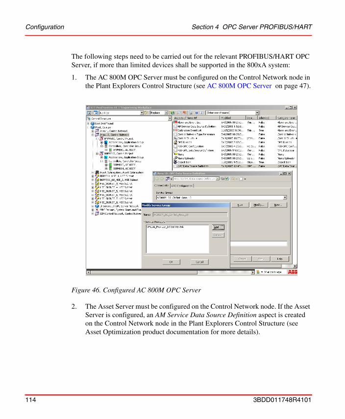
Configuration Section 4 OPC Server PROFIBUS/HART
The following steps need to be carried out for the relevant PROFIBUS/HART OPC Server, if more than limited devices shall be supported in the 800xA system:
1. The AC 800M OPC Server must be configured on the Control Network node in the Plant Explorers Control Structure (see AC 800M OPC Server on page 47).
2. The Asset Server must be configured on the Control Network node. If the Asset Server is configured, an AM Service Data Source Definition aspect is created on the Control Network node in the Plant Explorers Control Structure (see Asset Optimization product documentation for more details).
Figure 46. Configured AC 800M OPC Server
114 3BDD011748R4101
Section 4 OPC Server PROFIBUS/HART Configuration
3. Create a shared folder as described in Industrial IT, 800xA - System, Post Installation Setup 3BUA000156R4101 manual, section Shared Folder for PROFIBUS and HART Device Integration on all new Connectivity Server, where the PROFIBUS/HART OPC Server shall be executed. In this example 3 new Connectivity Server are required, which shall have the shared folder.
4. Open Plant Explorers Control Structure and select the Root node. Configure all new Connectivity Server in the FBB PH Settings aspect, as described in System 800xA Server Path Settings on page 35.
5. Configure the path settings for the PROFIBUS/HART OPC Server, if the shared folders are renamed and differ from the default. The configuration is described in Pre-configuration of the OPC Server PROFIBUS/HART on page 38.
6. Delete PROFIBUS/HART OPC Server configuration, if the OPC Server was already configured. In the case, that configuration of a PROFIBUS/HART OPC Server was not performed before, proceed with Step 7.
– Open Plant Explorers Control Structure and select the Control Network.
– Select the FBB-OPC Data Source Definition aspect in the Aspect window.
The default name of the shared folder is Fieldbus Builder PH. It is strictly recommended not to change default folder names and paths.
3BDD011748R4101 115
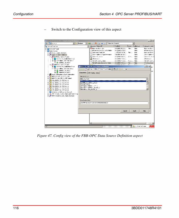
Configuration Section 4 OPC Server PROFIBUS/HART
– Switch to the Configuration view of this aspect
Figure 47. Config view of the FBB-OPC Data Source Definition aspect
116 3BDD011748R4101
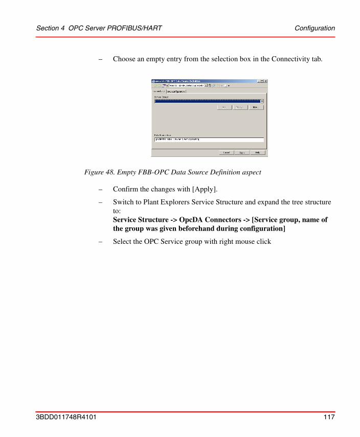
Section 4 OPC Server PROFIBUS/HART Configuration
– Choose an empty entry from the selection box in the Connectivity tab.
– Confirm the changes with [Apply].
– Switch to Plant Explorers Service Structure and expand the tree structure to:Service Structure -> OpcDA Connectors -> [Service group, name of the group was given beforehand during configuration]
– Select the OPC Service group with right mouse click
Figure 48. Empty FBB-OPC Data Source Definition aspect
3BDD011748R4101 117
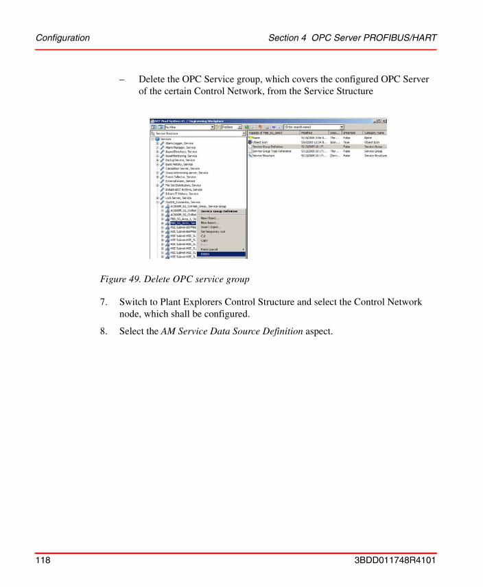
Configuration Section 4 OPC Server PROFIBUS/HART
– Delete the OPC Service group, which covers the configured OPC Server of the certain Control Network, from the Service Structure
7. Switch to Plant Explorers Control Structure and select the Control Network node, which shall be configured.
8. Select the AM Service Data Source Definition aspect.
Figure 49. Delete OPC service group
118 3BDD011748R4101
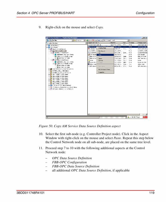
Section 4 OPC Server PROFIBUS/HART Configuration
9. Right-click on the mouse and select Copy.
10. Select the first sub-node (e.g. Controller Project node). Click in the Aspect Window with right-click on the mouse and select Paste. Repeat this step below the Control Network node on all sub-node, are placed on the same tree level.
11. Proceed step 7 to 10 with the following additional aspects at the Control Network node:
– OPC Data Source Definition– FBB-OPC Configuration– FBB-OPC Data Source Definition– all additional OPC Data Source Definition, if applicable
Figure 50. Copy AM Service Data Source Definition aspect
3BDD011748R4101 119
Configuration Section 4 OPC Server PROFIBUS/HART
12. Configure the copied FBB-OPC Data Source Definition aspect on all sub-nodes as described in OPC Server assignment to a Connectivity Server on page 43 (start with step 3).
13. Start the new configured OPC Server on the Connectivity Server as described in Starting OPC Server PROFIBUS/HART on page 68.
Notice, that each FBB-OPC Data Source Definition aspects requires a new Connectivity Server be assigned to.
The original FBB-OPC Data Source Definition aspect on the Control Network node must not be configured and shall not be assigned to an OPC Server.
120 3BDD011748R4101
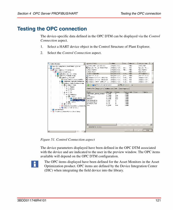
Section 4 OPC Server PROFIBUS/HART Testing the OPC connection
Testing the OPC connectionThe device-specific data defined in the OPC DTM can be displayed via the Control Connection aspect.
1. Select a HART device object in the Control Structure of Plant Explorer.
2. Select the Control Connection aspect.
The device parameters displayed have been defined in the OPC DTM associated with the device and are indicated to the user in the preview window. The OPC items available will depend on the OPC DTM configuration.
Figure 51. Control Connection aspect
The OPC items displayed have been defined for the Asset Monitors in the Asset Optimization product. OPC items are defined by the Device Integration Center (DIC) when integrating the field device into the library.
3BDD011748R4101 121
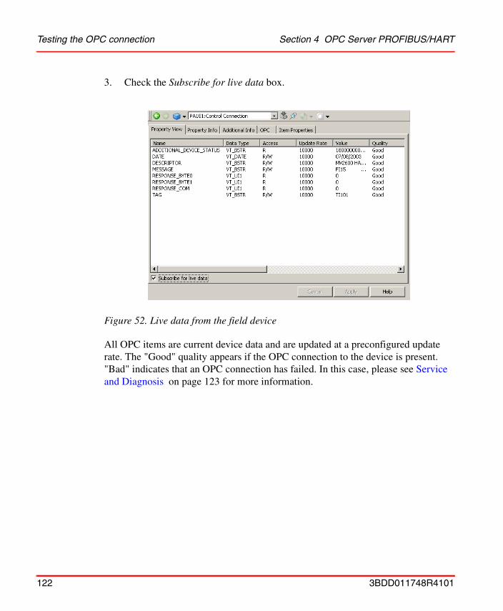
Testing the OPC connection Section 4 OPC Server PROFIBUS/HART
3. Check the Subscribe for live data box.
All OPC items are current device data and are updated at a preconfigured update rate. The "Good" quality appears if the OPC connection to the device is present. "Bad" indicates that an OPC connection has failed. In this case, please see Service and Diagnosis on page 123 for more information.
Figure 52. Live data from the field device
122 3BDD011748R4101
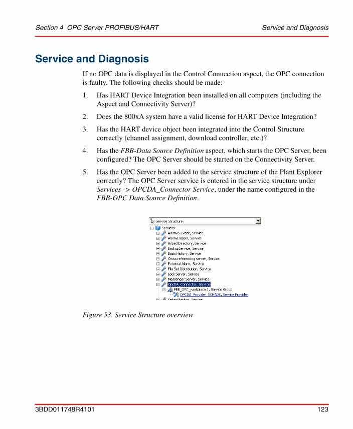
Section 4 OPC Server PROFIBUS/HART Service and Diagnosis
Service and DiagnosisIf no OPC data is displayed in the Control Connection aspect, the OPC connection is faulty. The following checks should be made:
1. Has HART Device Integration been installed on all computers (including the Aspect and Connectivity Server)?
2. Does the 800xA system have a valid license for HART Device Integration?
3. Has the HART device object been integrated into the Control Structure correctly (channel assignment, download controller, etc.)?
4. Has the FBB-Data Source Definition aspect, which starts the OPC Server, been configured? The OPC Server should be started on the Connectivity Server.
5. Has the OPC Server been added to the service structure of the Plant Explorer correctly? The OPC Server service is entered in the service structure under Services -> OPCDA_Connector Service, under the name configured in the FBB-OPC Data Source Definition.
Figure 53. Service Structure overview
3BDD011748R4101 123

Service and Diagnosis Section 4 OPC Server PROFIBUS/HART
6. Is the OPC Server service enabled in the service structure?
7. Once the FBB-OPC Data Source Definition has been configured correctly, the OPC Server must start automatically on the Connectivity Server. Check the OPC Server state in the Service Structure of the Plant Explorer workplace as described in step 5 and 6. Status can be checked in the tab Status of the Service (see step 6).
8. Has the FBB PH Settings aspect, which synchronizes the OPC files between the different Server, been configured?
9. Has the project path been entered correctly in the OPC Control Center?The path in the ABB OPC Server Control Center must lead to the OPC DTM XML files. In order to check the path setting, the OPC Control Center must be opened on the Connectivity Server.
Figure 54. Service Structure
124 3BDD011748R4101
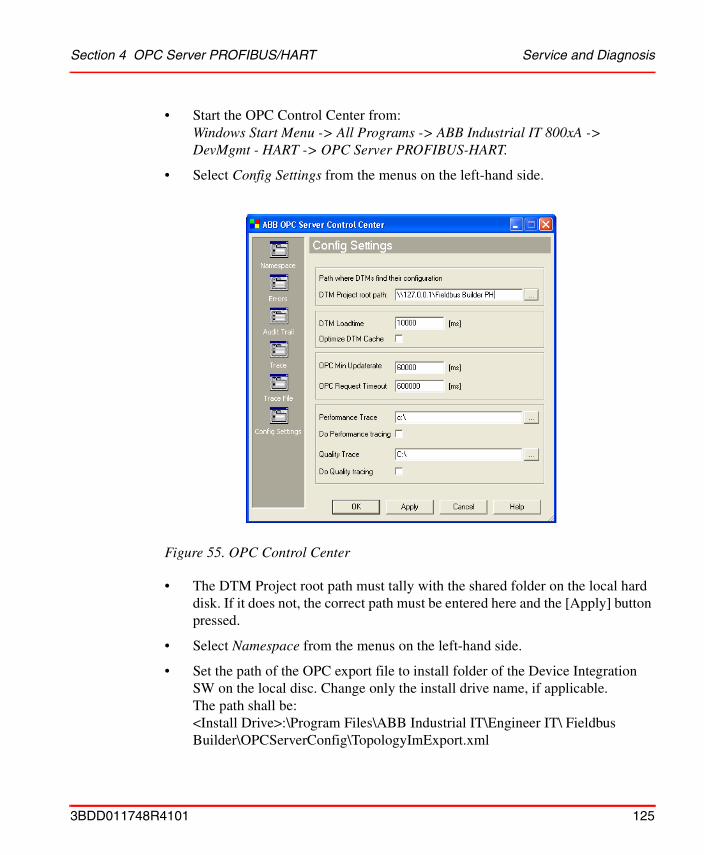
Section 4 OPC Server PROFIBUS/HART Service and Diagnosis
• Start the OPC Control Center from:Windows Start Menu -> All Programs -> ABB Industrial IT 800xA -> DevMgmt - HART -> OPC Server PROFIBUS-HART.
• Select Config Settings from the menus on the left-hand side.
• The DTM Project root path must tally with the shared folder on the local hard disk. If it does not, the correct path must be entered here and the [Apply] button pressed.
• Select Namespace from the menus on the left-hand side.
• Set the path of the OPC export file to install folder of the Device Integration SW on the local disc. Change only the install drive name, if applicable. The path shall be:<Install Drive>:\Program Files\ABB Industrial IT\Engineer IT\ Fieldbus Builder\OPCServerConfig\TopologyImExport.xml
Figure 55. OPC Control Center
3BDD011748R4101 125
Backup/Restore Section 4 OPC Server PROFIBUS/HART
• Click [Apply] and [OK].
• Once a change has been made, the OPC configuration must be reloaded to the OPC server. To do this, disable and enable the OPC Server Service in the Service Structure (see Pre-configuration of the OPC Server PROFIBUS/HART on page 38).
Backup/RestoreThe OPC Server PROFIBUS/HART saves the device topology as an xml file in the directory configured by the user via the FBB PH Settings Aspect, Example:\\Connectivity Server\Fieldbus Builder PH
During a system backup, an additional backup should be made of the directory.
After a successful system restore, the saved directory should be copied to the node(s).
All HART Device Integration settings and the relevant aspects should be checked after a successful backup and adapted as required.
Additional changes in the Control Center as described in this document may only be made by authorized personnel as they may affect the operability of the system. Please contact ABB Service before making any changes.
If all the steps listed have been followed correctly and you are still unable to access OPC items, please contact ABB Service.
Detailed information about the OPC Server and the configuration is provided in Pre-configuration of the OPC Server PROFIBUS/HART on page 38
The directory structure of the backup system should be retained during a system restore. The directories are to be enabled for access.
If redundant servers are used in the 800xA system, the directories of the redundant servers should be backed up and uploaded again after performing a restore.
126 3BDD011748R4101
Section 5 HART Device Integration Library
OverviewThe device libraries contain a portfolio of System 800xA tested and certified ABB and third party device objects, minimizing the effort of integration for 800xA system users. Each device is represented in the library by a device type object. ABB’s Device Integration Center (DIC) creates these objects for the user and enriches them with all aspects for efficient device management over the entire life cycle, from the design phase to operation and maintenance. To assure interoperability of the system with the device and the related components, the new device type object is tested against the real device.
If a device type is not available in the library, please contact the Device Integration Center to request the integration of an additional device type. The Device Integration Center will add the new device object to one of the next library versions.
Please contact the DIC for further information:
ABB Automation GmbHDevice Integration CenterSchillerstr. 72 32425 Minden
Fax.: +49 571 830 1871Mail: [email protected]
3BDD011748R4101 127
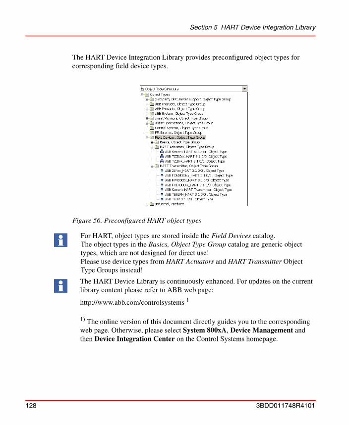
Section 5 HART Device Integration Library
The HART Device Integration Library provides preconfigured object types for corresponding field device types.
Figure 56. Preconfigured HART object types
For HART, object types are stored inside the Field Devices catalog. The object types in the Basics, Object Type Group catalog are generic object types, which are not designed for direct use! Please use device types from HART Actuators and HART Transmitter Object Type Groups instead!
The HART Device Library is continuously enhanced. For updates on the current library content please refer to ABB web page:
http://www.abb.com/controlsystems 1
1) The online version of this document directly guides you to the corresponding web page. Otherwise, please select System 800xA, Device Management and then Device Integration Center on the Control Systems homepage.
128 3BDD011748R4101
Section 5 HART Device Integration Library Functionality
FunctionalityThe preconfigured device object types enable each device to:
• access device-specific components for
– configuration, commissioning, and diagnostics via Device Type Manager
– access to device-specific documentation
• access 800xA System functionality
– Alarm and Event Lists
– Audit Trail
• access Asset Optimizer Asset Optimizer allow plant personnel to collect, compare, and monitor field device data in order to accurately assess equipment conditions.
• access Device Management System DMS (optional)Device Management System (DMS) allow plant personnel to store, distribute and to manage calibration data from HART devices in the 800xA System.
Integration of new HART Device Object TypesThe HART Device Integration Library covers a basic set of object types for different HART devices. This Device Integration Library can be enhanced with additional object types, downloadable via ABB Solutionsbank. By using the Device Library Wizard, new device object can be imported to the 800xA system.
For a complete list of currently supported devices and functionality, please refer to the Release Notes of this product listed in Relevant Documentation on page 15!
Further information on the Device Library Wizard and single device object types can be found in Section 6, Device Library Wizard (optional) on page 141.
3BDD011748R4101 129
Pre-configured Aspects in the Object Type Structure Section 5 HART Device Integration Library
Pre-configured Aspects in the Object Type StructureThe Object Type Structure contains the device objects to be used in the projects.
HART device object types are integrated in the 800xA system by installing the HART Device Integration as well as by loading the HART Device Integration system extensions. Additional device object types will be loaded to the system via Device Library Wizard. Depending on the system license features can be used without additional configuration work.
The following aspects are attached to each HART device object type:
• NameName of the device object type
• Install <DTM>Reference to the installation program of a device-specific DTM, for which a manufacturer's license must be held at the time of installation. The use of this aspect is described in Installation of Device Type Manager (DTM) on page 33.
• Product DocumentationAccess to various device specific documentation. For accessing a single document, please refer to Accessing device specific documentation on page 131.
• HART <generic/specific> Asset MonitorAsset Monitor acquire and analyze asset status and condition information. They notify operators and maintenance personnel when an abnormal condition calls for maintenance action.
• DIP Asset Object Types Extension DefinitionThis aspect handles the Asset Optimization aspects during instantiation
• DIP CMMS Object Type Extension DefinitionThis aspect handles the CMMS aspects during instantiation
• DIP Maximo Object Type Extension DefinitionThis aspect handles the Maximo CMMS aspects during instantiation
130 3BDD011748R4101
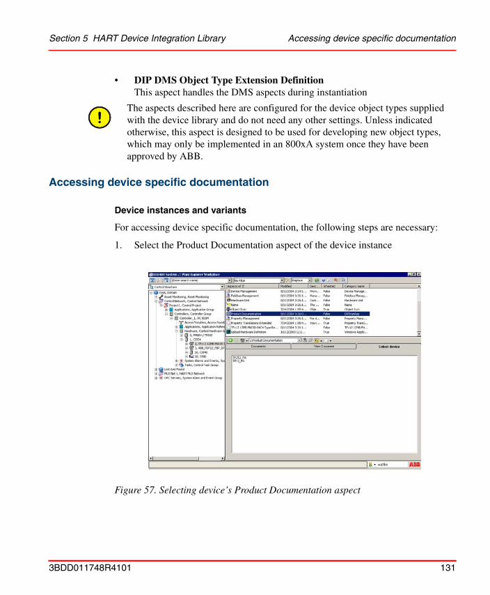
Section 5 HART Device Integration Library Accessing device specific documentation
• DIP DMS Object Type Extension DefinitionThis aspect handles the DMS aspects during instantiation
Accessing device specific documentation
Device instances and variants
For accessing device specific documentation, the following steps are necessary:
1. Select the Product Documentation aspect of the device instance
The aspects described here are configured for the device object types supplied with the device library and do not need any other settings. Unless indicated otherwise, this aspect is designed to be used for developing new object types, which may only be implemented in an 800xA system once they have been approved by ABB.
Figure 57. Selecting device’s Product Documentation aspect
3BDD011748R4101 131
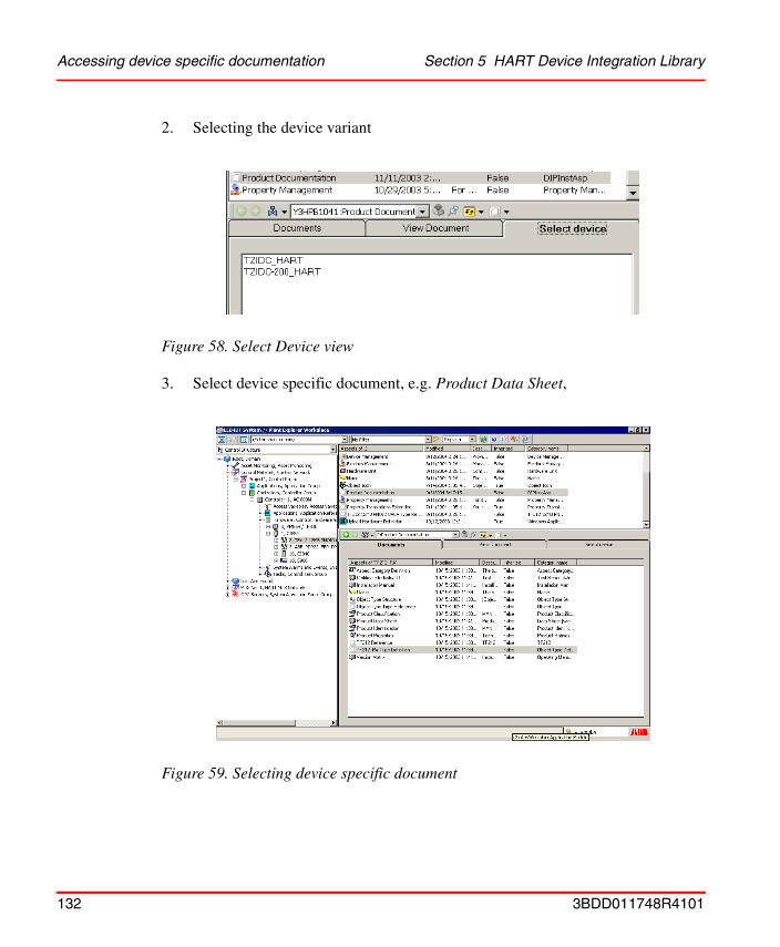
Accessing device specific documentation Section 5 HART Device Integration Library
2. Selecting the device variant
3. Select device specific document, e.g. Product Data Sheet,
Figure 58. Select Device view
Figure 59. Selecting device specific document
132 3BDD011748R4101
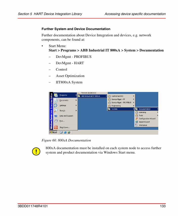
Section 5 HART Device Integration Library Accessing device specific documentation
Further System and Device Documentation
Further documentation about Device Integration and devices, e.g. network components, can be found at:
• Start Menu: Start > Programs > ABB Industrial IT 800xA > System > Documentation
– DevMgmt - PROFIBUS
– DevMgmt - HART
– Control
– Asset Optimization
– IIT800xA System
Figure 60. 800xA Documentation
800xA documentation must be installed on each system node to access further system and product documentation via Windows Start menu.
3BDD011748R4101 133
Connection to Asset Optimization Section 5 HART Device Integration Library
Connection to Asset OptimizationAsset Optimization consists of system extensions that allow plant personnel to collect, compare, and monitor field device data in order to accurately assess equipment conditions.
Information can subsequently be used to set future performance and profitability goals and to assist managers in making these decisions.
The Optimize IT Asset Optimization software consists of the following components, for which the Device Integration Library provides a connection for its preconfigured field device types.
Asset Monitoring
Asset Monitoring provides the infrastructure that monitors, analyzes, and reports asset status/condition information. It notifies operators and maintenance personnel when an abnormal condition calls for maintenance. Asset Monitoring interacts with third-party CMMS applications to optimize the use of plant equipment and processes.An Asset Monitor is an application for retrieving data from, and interacting with, multiple data servers, e.g. OPC Servers. Asset Monitors can detect problems that may not affect the process variables, but do affect the maintenance status of an asset or process.
The ABB Asset Optimization product must be installed.
134 3BDD011748R4101
Section 5 HART Device Integration Library Asset Monitoring
Asset Monitoring library aspects
The aspects listed in Table 10are added to the field device types, if the related software option is installed and licensed.
Table 10. DIP Asset Object Types Extension Definition
Aspect Function
Asset Reporter The Asset Reporter provides a detailed view of an asset condition for an object.
It displays information available to it from all Asset Monitors and their corresponding current sub-conditions.
Asset Viewer When the Asset Viewer is added to an object, the Asset Condition Tree can be displayed. When displayed, the Asset Condition Tree shows the condition of that object and all its children, visually indicating the presence of a fault report by displaying items in bold text.
Context menus permit fault report submission directly from within the Asset Viewer.
HART Generic Device Asset Monitor
Generic asset monitor for devices for monitoring the status byte states of HART device.
HART <specific> Device Asset Monitor (optional)
Specific asset monitor for devices for monitoring device specific conditions of HART device.
3BDD011748R4101 135

CMMS Connectivity Section 5 HART Device Integration Library
CMMS Connectivity
CMMS Connectivity establishes the link that removes the barrier to information exchange between the Computerized Maintenance Management System (CMMS) and the process control system environments and brings maintenance management to the operator environment.
Context menus for process graphics, the alarm and event list, etc. provide access to a number of views and actions for the specific CMMS item.
This allows plant personnel to collect, compare, and monitor field device data in order to accurately assess equipment conditions.
The Asset Optimizer and CMMS products must be installed.
Please refer to the Release Notes of this product listed in Relevant Documentation on page 15 and to the Asset Optimization documentation for detailed information of supported Computerized Maintenance Management System (CMMS).
136 3BDD011748R4101
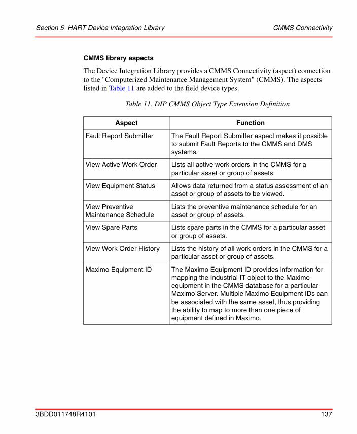
Section 5 HART Device Integration Library CMMS Connectivity
CMMS library aspects
The Device Integration Library provides a CMMS Connectivity (aspect) connection to the "Computerized Maintenance Management System" (CMMS). The aspects listed in Table 11 are added to the field device types.
Table 11. DIP CMMS Object Type Extension Definition
Aspect Function
Fault Report Submitter The Fault Report Submitter aspect makes it possible to submit Fault Reports to the CMMS and DMS systems.
View Active Work Order Lists all active work orders in the CMMS for a particular asset or group of assets.
View Equipment Status Allows data returned from a status assessment of an asset or group of assets to be viewed.
View Preventive Maintenance Schedule
Lists the preventive maintenance schedule for an asset or group of assets.
View Spare Parts Lists spare parts in the CMMS for a particular asset or group of assets.
View Work Order History Lists the history of all work orders in the CMMS for a particular asset or group of assets.
Maximo Equipment ID The Maximo Equipment ID provides information for mapping the Industrial IT object to the Maximo equipment in the CMMS database for a particular Maximo Server. Multiple Maximo Equipment IDs can be associated with the same asset, thus providing the ability to map to more than one piece of equipment defined in Maximo.
3BDD011748R4101 137
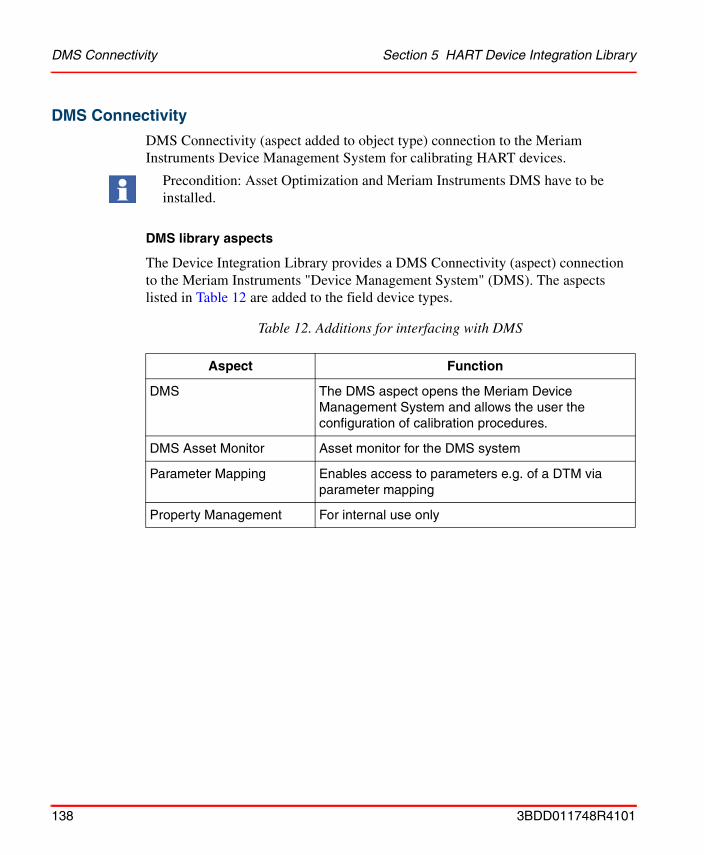
DMS Connectivity Section 5 HART Device Integration Library
DMS Connectivity
DMS Connectivity (aspect added to object type) connection to the Meriam Instruments Device Management System for calibrating HART devices.
DMS library aspects
The Device Integration Library provides a DMS Connectivity (aspect) connection to the Meriam Instruments "Device Management System" (DMS). The aspects listed in Table 12 are added to the field device types.
Precondition: Asset Optimization and Meriam Instruments DMS have to be installed.
Table 12. Additions for interfacing with DMS
Aspect Function
DMS The DMS aspect opens the Meriam Device Management System and allows the user the configuration of calibration procedures.
DMS Asset Monitor Asset monitor for the DMS system
Parameter Mapping Enables access to parameters e.g. of a DTM via parameter mapping
Property Management For internal use only
138 3BDD011748R4101
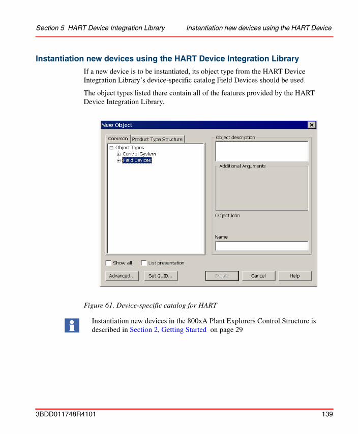
Section 5 HART Device Integration Library Instantiation new devices using the HART Device
Instantiation new devices using the HART Device Integration Library
If a new device is to be instantiated, its object type from the HART Device Integration Library’s device-specific catalog Field Devices should be used.
The object types listed there contain all of the features provided by the HART Device Integration Library.
Figure 61. Device-specific catalog for HART
Instantiation new devices in the 800xA Plant Explorers Control Structure is described in Section 2, Getting Started on page 29
3BDD011748R4101 139

Instantiation new devices using the HART Device Integration Library Section 5 HART Device
140 3BDD011748R4101
Section 6 Device Library Wizard (optional)
OverviewFor easy integration of fieldbus devices into the Industrial IT 800xA environment ABB provides a continuously increasing set of pre-integrated HART device types in the form of a single device object types. The Device Library Wizard is a tool that is used for adding these separately delivered device object types to the device libraries of an 800xA system.
The Device Library Wizard is not an integral part of the HART Device Integration and must be downloaded manually from the ABB Solutionsbank.
Solutionsbank is accessible via internet link:
• http://solutionsbank.abb.com
System RequirementsThe Device Library Wizard will be installed and operate on an Industrial IT 800xA system node. The system requirements relating to the operating system, CPU performance, memory capacity etc. are more than adequate for the installation and operation of the Device Library Wizard software. There are no additional or different requirements to the hard- and software environment for this tool. The system requirements are described in the Industrial IT, 800xA System, Installation document.
3BDD011748R4101 141
How to use the Device Library Wizard Section 6 Device Library Wizard (optional)
Prerequisites
The following requirements must be met to allow adding device object types to the device libraries of an 800xA system using the Device Library Wizard.
• An 800xA system has been created and started.
• All required 800xA licenses are loaded to the License Server.
• The HART Device Integration system extensions have been added. The required system extensions are described in Prerequisites and Requirements on page 29.
• The Device Library Wizard has been installed on every 800xA system node.
• The user has Windows administrator privileges.
How to use the Device Library WizardPre-integrated device types for the Industrial IT 800xA environment are available from ABB Solutionsbank for all supported fieldbus protocols in the form of device object types. This section describes the process of adding these device object types to an Industrial IT 800xA system using the Device Library Wizard tool.
Adding device object types to the system requires to carry out the following steps:
• Step 1: Download device Library Wizard from ABB Solutionsbank.
• Step 2: Download designated device object types (zip archives) from ABB Solutionsbank.
• Step 3: Extract and install the Device Library Wizard tool.
• Step 4: Extract the zip archives containing the device object types to Device Integration Library folders on all involved 800xA nodes.
• Step 5: Read corresponding device object type, product and system release notes for details and limitations.
• Step 6: Perform fieldbus protocol specific pre-installation actions.
• Step 7: Add the designated device object types to the 800xA system utilizing Device Library Wizard on all involved 800xA system nodes.
142 3BDD011748R4101

Section 6 Device Library Wizard (optional) How to use the Device Library Wizard
• Step 8: Perform fieldbus protocol specific post-installation actions.
Detailed information about how to use the Device Library Wizard can be found in Device Library Wizard User Instructions 3BDD011857.
Please read also the corresponding Release Notes.
3BDD011748R4101 143

How to use the Device Library Wizard Section 6 Device Library Wizard (optional)
144 3BDD011748R4101
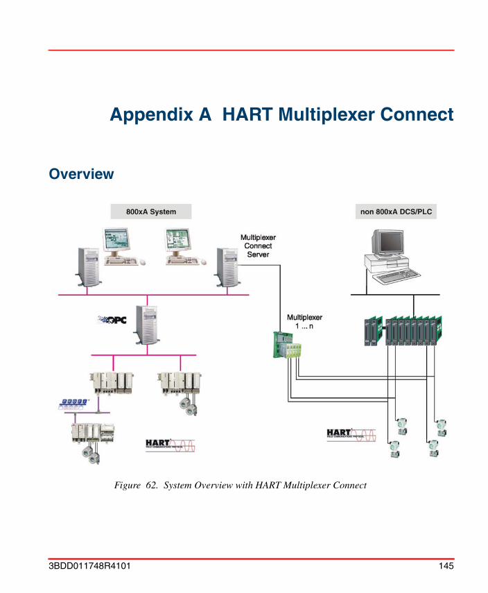
Appendix A HART Multiplexer Connect
Overview
Figure 62. System Overview with HART Multiplexer Connect
3BDD011748R4101 145
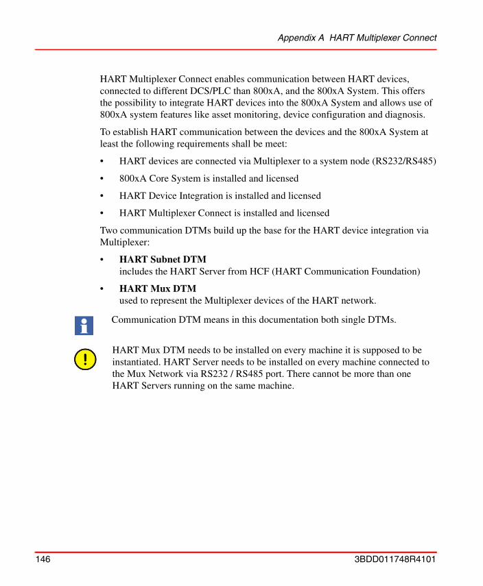
Appendix A HART Multiplexer Connect
HART Multiplexer Connect enables communication between HART devices, connected to different DCS/PLC than 800xA, and the 800xA System. This offers the possibility to integrate HART devices into the 800xA System and allows use of 800xA system features like asset monitoring, device configuration and diagnosis.
To establish HART communication between the devices and the 800xA System at least the following requirements shall be meet:
• HART devices are connected via Multiplexer to a system node (RS232/RS485)
• 800xA Core System is installed and licensed
• HART Device Integration is installed and licensed
• HART Multiplexer Connect is installed and licensed
Two communication DTMs build up the base for the HART device integration via Multiplexer:
• HART Subnet DTM includes the HART Server from HCF (HART Communication Foundation)
• HART Mux DTM used to represent the Multiplexer devices of the HART network.
Communication DTM means in this documentation both single DTMs.
HART Mux DTM needs to be installed on every machine it is supposed to be instantiated. HART Server needs to be installed on every machine connected to the Mux Network via RS232 / RS485 port. There cannot be more than one HART Servers running on the same machine.
146 3BDD011748R4101
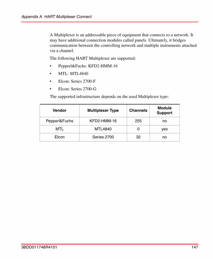
Appendix A HART Multiplexer Connect
A Multiplexer is an addressable piece of equipment that connects to a network. It may have additional connection modules called panels. Ultimately, it bridges communication between the controlling network and multiple instruments attached via a channel.
The following HART Multiplexer are supported:
• Pepperl&Fuchs: KFD2-HMM-16
• MTL: MTL4840
• Elcon: Series 2700-F
• Elcon: Series 2700-G
The supported infrastructure depends on the used Multiplexer type:
Vendor Multiplexer Type ChannelsModule Support
Pepperl&Fuchs KFD2-HMM-16 255 no
MTL MTL4840 0 yes
Elcon Series 2700 32 no
3BDD011748R4101 147
Notes for use Appendix A HART Multiplexer Connect
Notes for useThe HART Multiplexer software is included in the HART Device Integration and can be installed as option via the HART Device Integration setup. A separate license has be bought from the 800xA price list to enable HART Multiplexer Connect.
All aspects for HART device access via Multiplexer are integrated with the installation/when the field device objects are instantiated.
The OPC Server PROFIBUS/HART provides device-specific data to the Asset Monitors, which are supplied with the device library for the individual device objects.
Additional RequirementsThe operation of the HART Multiplexer Connect package requires the correct installation of the HART Server version 2.1, done during installation of the HART Device Integration. Please pay special attention to the description for DCOM configuration, especially if you want to use the OPC Server and the HART Connect package on different hosts.
It is only allowed to run the OPC Server PROFIBUS/HART on a single Connectivity Server. Each control network or sub components containing the aspect for OPC Server connectivity needs therefore its own Connectivity Server.
Asset Monitors will only run with the field device library if the "Asset Optimization" option is installed in the system. For more information, see Section 5, HART Device Integration Library.
All aspects of Hart Multiplexer Connect described in this section are pre-configured and may not be modified by the user if not mentioned in this manual. ABB Service must be informed before the user makes any changes to the aspects described in this document.
Limitations and restrictions of the HART Multiplexer software are described in the related Release Notes.
148 3BDD011748R4101
Appendix A HART Multiplexer Connect Functionality
The HART Multiplexer Connect supports the operating systems Windows 2000 and Windows XP.
FunctionalityThe Communication DTMs of HART Multiplexer Connect are implemented according to FDT 1.2 (Addendum). In the following paragraphs support for specific functionality is described in more detail:
Multi User support
The DTM supports multi user scenarios according to the FDT specification by Locking/Unlocking the data set and exchanging the data set changes via the FDT/DTM-Mechanism.
A DTM locks the data set if a DTM window is opened, that can be used to change the data set. The lock is released when the DTM window is closed. When the stored data set was changed by these procedures, the DTM sends an event to the Fieldbus Builder PROFIBUS/HART, which is responsible for distributing the event to all DTMs that are using the same parameter set. If a DTM receives such event, it uses the accompanying information to update its data set.
If a DTM window is opened and the data set is already locked by another DTM, the dialog elements, that are used for changing the data set, are disabled. If the data set changes are distributed, the displayed information is updated in the DTM dialogs.
Audit Trail
HART Multiplexer Connect with its Communication DTMs support Audit Trail session according FDT specification. Following Audit Trail events are issued:
• Change of parameter
• Change of online state
• Call of functions
The uses has to have Windows Administrator rights to configure the HART Multiplexer Connect. Windows Administrator rights are not needed to access online data from HART devices and to do device configuration.
3BDD011748R4101 149
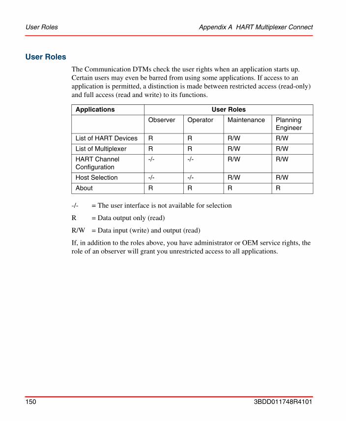
User Roles Appendix A HART Multiplexer Connect
User Roles
The Communication DTMs check the user rights when an application starts up. Certain users may even be barred from using some applications. If access to an application is permitted, a distinction is made between restricted access (read-only) and full access (read and write) to its functions.
-/- = The user interface is not available for selection
R = Data output only (read)
R/W = Data input (write) and output (read)
If, in addition to the roles above, you have administrator or OEM service rights, the role of an observer will grant you unrestricted access to all applications.
Applications User Roles
Observer Operator Maintenance Planning Engineer
List of HART Devices R R R/W R/W
List of Multiplexer R R R/W R/W
HART Channel Configuration
-/- -/- R/W R/W
Host Selection -/- -/- R/W R/W
About R R R R
150 3BDD011748R4101
Appendix A HART Multiplexer Connect Pre-configuration
Pre-configurationA preconfiguration have been performed before working with Multiplexer networks.
Proceed with the following steps described in Section 2, Getting Started:
1. Prerequisites and Requirements on page 29
2. Installation of Device Type Manager (DTM) on page 33.
3. System 800xA Server Path Settings on page 35.
4. Pre-configuration of the OPC Server PROFIBUS/HART on page 38.
Multinode Environment
The HART Multiplexer Connect package with its HART Server can be used in multi-node environments. This means, that one system node is connected via serial interface to the Multiplexer, but all collected device data are distributed through the 800xA System to the clients. The HART Server shall be installed on the Windows 2000 or XP Workstation to which the Multiplexer hardware is connected via serial port (e.g. COM1).
The user account is configured using the Windows system tool DCOMcnfg. The following steps have been performed on every system node, working as client for the HART Server (see Client Configuration on page 155) and on the HART Server node (see Server Configuration on page 156):
1. Click on the Windows Start button in the task bar.
2. Select the menu Run....
3. Enter dcomcnfg in the text line.
– DCOM configuration window appears (follow the steps below for the individual operating system, then go ahead with step 4)
3BDD011748R4101 151
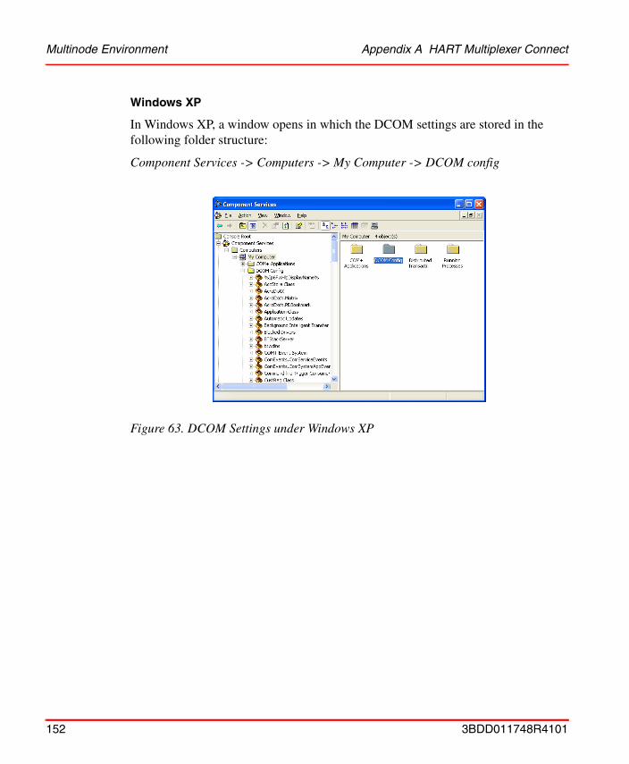
Multinode Environment Appendix A HART Multiplexer Connect
Windows XP
In Windows XP, a window opens in which the DCOM settings are stored in the following folder structure:
Component Services -> Computers -> My Computer -> DCOM config
Figure 63. DCOM Settings under Windows XP
152 3BDD011748R4101
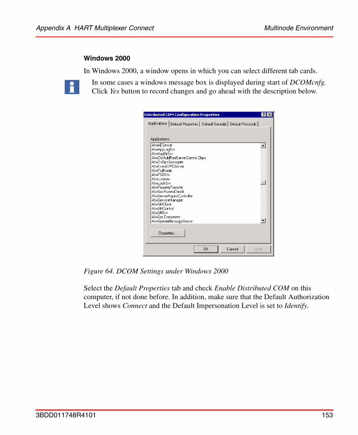
Appendix A HART Multiplexer Connect Multinode Environment
Windows 2000
In Windows 2000, a window opens in which you can select different tab cards.
Select the Default Properties tab and check Enable Distributed COM on this computer, if not done before. In addition, make sure that the Default Authorization Level shows Connect and the Default Impersonation Level is set to Identify.
In some cases a windows message box is displayed during start of DCOMcnfg. Click Yes button to record changes and go ahead with the description below.
Figure 64. DCOM Settings under Windows 2000
3BDD011748R4101 153
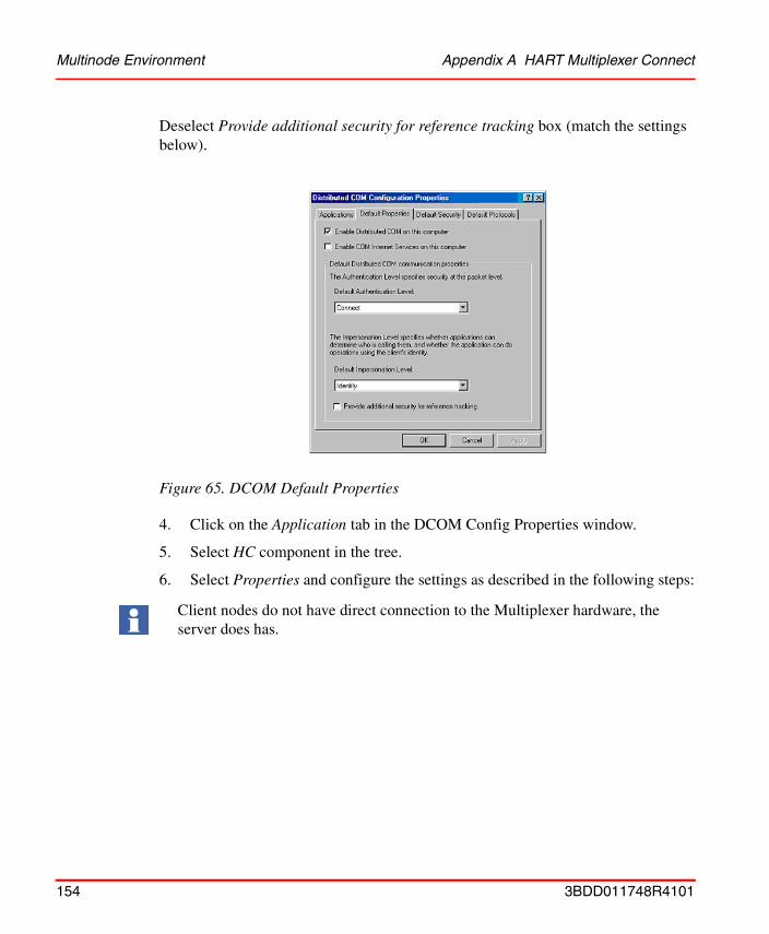
Multinode Environment Appendix A HART Multiplexer Connect
Deselect Provide additional security for reference tracking box (match the settings below).
4. Click on the Application tab in the DCOM Config Properties window.
5. Select HC component in the tree.
6. Select Properties and configure the settings as described in the following steps:
Figure 65. DCOM Default Properties
Client nodes do not have direct connection to the Multiplexer hardware, the server does has.
154 3BDD011748R4101

Appendix A HART Multiplexer Connect Multinode Environment
Client Configuration
Perform the following DCOM configuration steps on every client, using HART Multiplexer Connect.
1. Select Location tab.
2. Check Run Application on the following computer.
3. Insert IP address or the host name of the system node, where the HART Server is running. To search the system node in the network, use the Browse button.
4. Select Identity tab.
5. Check Interactive user.
6. Click [Apply] and [OK].
Figure 66. Location tab for clients
3BDD011748R4101 155
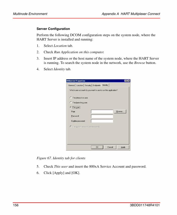
Multinode Environment Appendix A HART Multiplexer Connect
Server Configuration
Perform the following DCOM configuration steps on the system node, where the HART Server is installed and running:
1. Select Location tab.
2. Check Run Application on this computer.
3. Insert IP address or the host name of the system node, where the HART Server is running. To search the system node in the network, use the Browse button.
4. Select Identity tab.
5. Check This user and insert the 800xA Service Account and password.
6. Click [Apply] and [OK].
Figure 67. Identity tab for clients
156 3BDD011748R4101
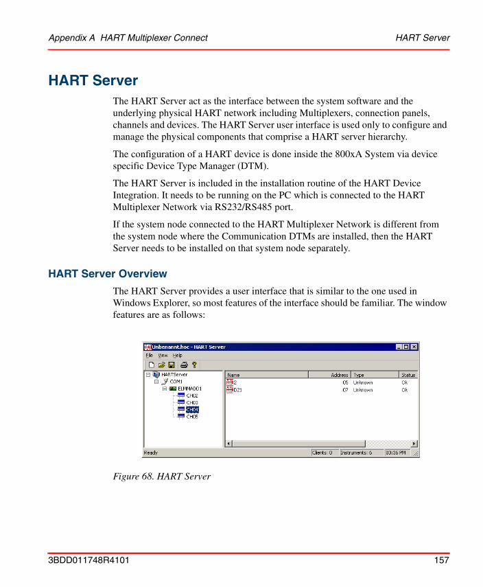
Appendix A HART Multiplexer Connect HART Server
HART ServerThe HART Server act as the interface between the system software and the underlying physical HART network including Multiplexers, connection panels, channels and devices. The HART Server user interface is used only to configure and manage the physical components that comprise a HART server hierarchy.
The configuration of a HART device is done inside the 800xA System via device specific Device Type Manager (DTM).
The HART Server is included in the installation routine of the HART Device Integration. It needs to be running on the PC which is connected to the HART Multiplexer Network via RS232/RS485 port.
If the system node connected to the HART Multiplexer Network is different from the system node where the Communication DTMs are installed, then the HART Server needs to be installed on that system node separately.
HART Server Overview
The HART Server provides a user interface that is similar to the one used in Windows Explorer, so most features of the interface should be familiar. The window features are as follows:
Figure 68. HART Server
3BDD011748R4101 157
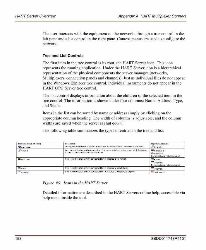
HART Server Overview Appendix A HART Multiplexer Connect
The user interacts with the equipment on the networks through a tree control in the left pane and a list control in the right pane. Context menus are used to configure the network.
Tree and List Controls
The first item in the tree control is its root, the HART Server icon. This icon represents the running application. Under the HART Server icon is a hierarchical representation of the physical components the server manages (networks, Multiplexers, connection panels and channels). Just as individual files do not appear in the Windows Explorer tree control, individual instruments do not appear in the HART OPC Server tree control.
The list control displays information about the children of the selected item in the tree control. The information is shown under four columns: Name, Address, Type, and Status.
Items in the list can be sorted by name or address simply by clicking on the appropriate column heading. The width of columns is adjustable, and the column widths are saved when the server is shut down.
The following table summarizes the types of entries in the tree and list.
Detailed information are described in the HART Servers online help, accessible via help menu inside the tool.
Figure 69. Icons in the HART Server
158 3BDD011748R4101
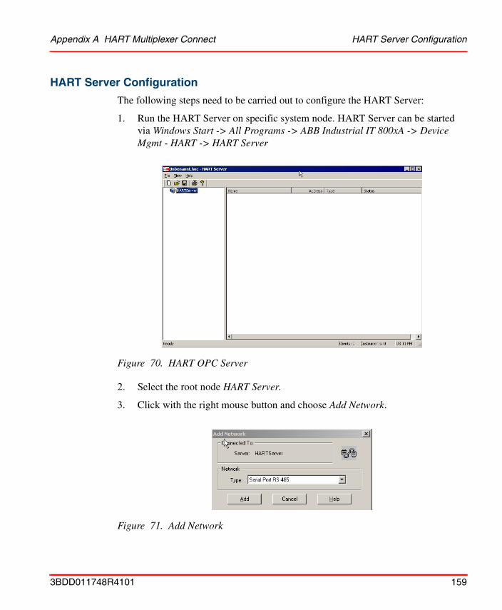
Appendix A HART Multiplexer Connect HART Server Configuration
HART Server Configuration
The following steps need to be carried out to configure the HART Server:
1. Run the HART Server on specific system node. HART Server can be started via Windows Start -> All Programs -> ABB Industrial IT 800xA -> Device Mgmt - HART -> HART Server
2. Select the root node HART Server.
3. Click with the right mouse button and choose Add Network.
Figure 70. HART OPC Server
Figure 71. Add Network
3BDD011748R4101 159
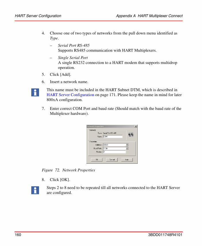
HART Server Configuration Appendix A HART Multiplexer Connect
4. Choose one of two types of networks from the pull down menu identified as Type.
– Serial Port RS-485Supports RS485 communication with HART Multiplexers.
– Single Serial PortA single RS232 connection to a HART modem that supports multidrop operation.
5. Click [Add].
6. Insert a network name.
7. Enter correct COM Port and baud rate (Should match with the baud rate of the Multiplexer hardware).
8. Click [OK].
This name must be included in the HART Subnet DTM, which is described in HART Server Configuration on page 171. Please keep the name in mind for later 800xA configuration.
Figure 72. Network Properties
Steps 2 to 8 need to be repeated till all networks connected to the HART Server are configured.
160 3BDD011748R4101
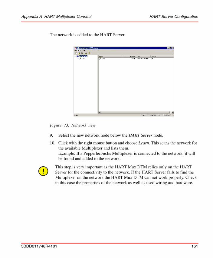
Appendix A HART Multiplexer Connect HART Server Configuration
The network is added to the HART Server.
9. Select the new network node below the HART Server node.
10. Click with the right mouse button and choose Learn. This scans the network for the available Multiplexer and lists them. Example: If a Pepperl&Fuchs Multiplexer is connected to the network, it will be found and added to the network.
Figure 73. Network view
This step is very important as the HART Mux DTM relies only on the HART Server for the connectivity to the network. If the HART Server fails to find the Multiplexer on the network the HART Mux DTM can not work properly. Check in this case the properties of the network as well as used wiring and hardware.
3BDD011748R4101 161
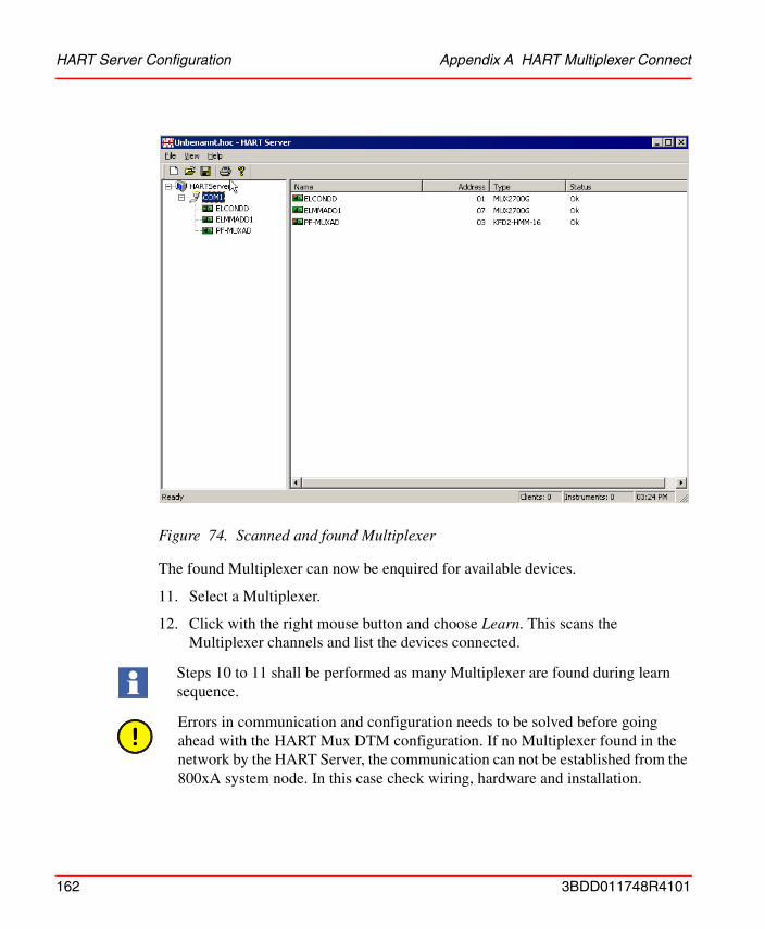
HART Server Configuration Appendix A HART Multiplexer Connect
The found Multiplexer can now be enquired for available devices.
11. Select a Multiplexer.
12. Click with the right mouse button and choose Learn. This scans the Multiplexer channels and list the devices connected.
Figure 74. Scanned and found Multiplexer
Steps 10 to 11 shall be performed as many Multiplexer are found during learn sequence.
Errors in communication and configuration needs to be solved before going ahead with the HART Mux DTM configuration. If no Multiplexer found in the network by the HART Server, the communication can not be established from the 800xA system node. In this case check wiring, hardware and installation.
162 3BDD011748R4101
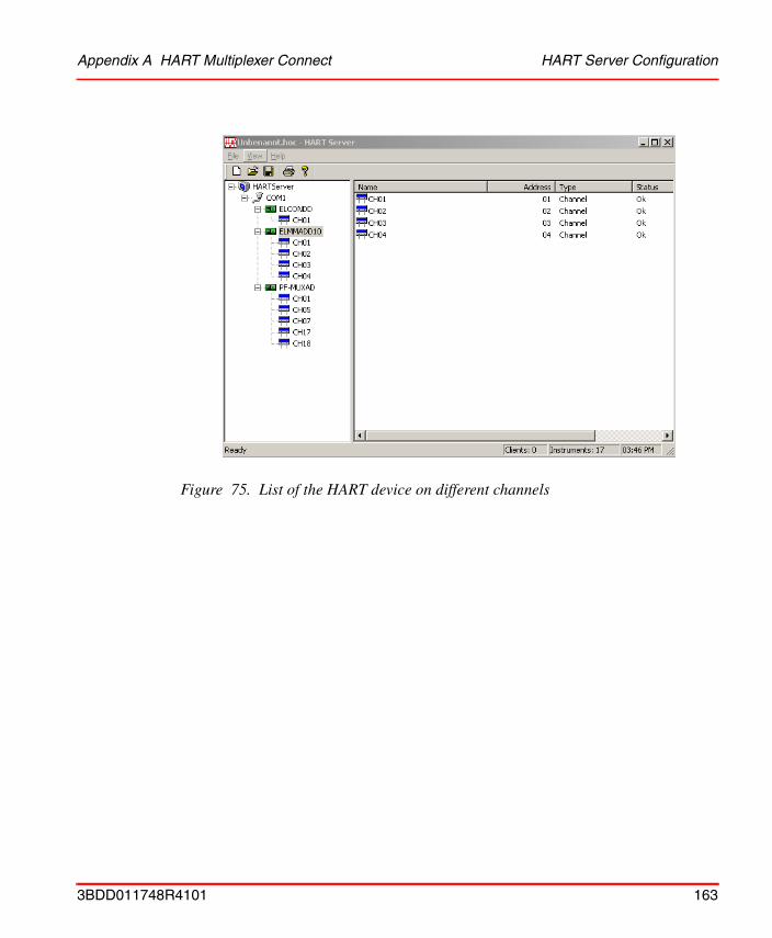
Appendix A HART Multiplexer Connect HART Server Configuration
Figure 75. List of the HART device on different channels
3BDD011748R4101 163
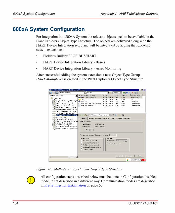
800xA System Configuration Appendix A HART Multiplexer Connect
800xA System ConfigurationFor integration into 800xA System the relevant objects need to be available in the Plant Explorers Object Type Structure. The objects are delivered along with the HART Device Integration setup and will be integrated by adding the following system extensions:
• Fieldbus Builder PROFIBUS/HART
• HART Device Integration Library - Basics
• HART Device Integration Library - Asset Monitoring
After successful adding the system extension a new Object Type Group HART Multiplexer is created in the Plant Explorers Object Type Structure.
Figure 76. Multiplexer object in the Object Type Structure
All configuration steps described below must be done in Configuration disabled mode, if not described in a different way. Communication modes are described in Pre-settings for Instantiation on page 53
164 3BDD011748R4101

Appendix A HART Multiplexer Connect Create a new HART Multiplexer Network
Create a new HART Multiplexer Network
The following steps need to be carried out:
1. Open Plant Explorers Control Structure.
2. Select the root node.
3. Right-click on the mouse and select New Object.
4. Browse to Object Types -> HART Multiplexer -> HART Multiplexer Network.
5. Insert an object name and click [Create].
Figure 77. Select New Object...
Figure 78. Adding a new HART Multiplexer Network
3BDD011748R4101 165
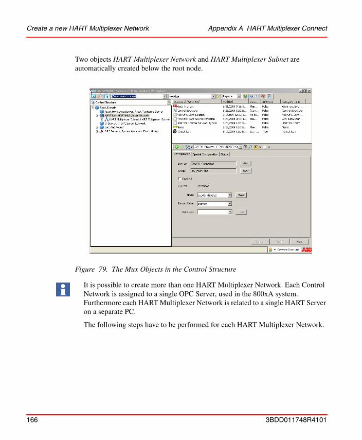
Create a new HART Multiplexer Network Appendix A HART Multiplexer Connect
Two objects HART Multiplexer Network and HART Multiplexer Subnet are automatically created below the root node.
Figure 79. The Mux Objects in the Control Structure
It is possible to create more than one HART Multiplexer Network. Each Control Network is assigned to a single OPC Server, used in the 800xA system. Furthermore each HART Multiplexer Network is related to a single HART Server on a separate PC.
The following steps have to be performed for each HART Multiplexer Network.
166 3BDD011748R4101

Appendix A HART Multiplexer Connect Assignment of the OPC Server PROFIBUS/HART to a
Assignment of the OPC Server PROFIBUS/HART to a Connectivity Server
A Connectivity Server on which the OPC Server PROFIBUS/HART can be executed is assigned to each HART Multiplexer Network.
1. Select the HART Multiplexer Network.
2. Select FBB-OPC Data Source Definition aspect
Only one OPC Server PROFIBUS/HART can be started per Connectivity Server. OPC Servers for other software options, for example the HART Server, can also be executed on the same Connectivity Servers.
Figure 80. HART Multiplexer Network
The following steps should be carried out for each HART Multiplexer Network which is placed in the system and contains the FBB-OPC Data Source Definition Aspect.
3BDD011748R4101 167
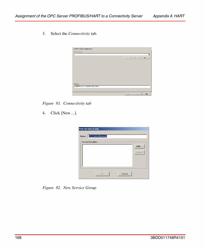
Assignment of the OPC Server PROFIBUS/HART to a Connectivity Server Appendix A HART
3. Select the Connectivity tab.
4. Click [New…].
Figure 81. Connectivity tab
Figure 82. New Service Group
168 3BDD011748R4101
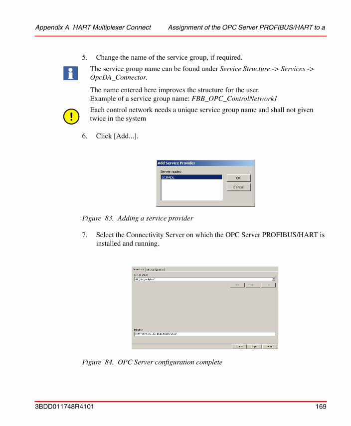
Appendix A HART Multiplexer Connect Assignment of the OPC Server PROFIBUS/HART to a
5. Change the name of the service group, if required.
6. Click [Add...].
7. Select the Connectivity Server on which the OPC Server PROFIBUS/HART is installed and running.
The service group name can be found under Service Structure -> Services -> OpcDA_Connector.
The name entered here improves the structure for the user. Example of a service group name: FBB_OPC_ControlNetwork1
Each control network needs a unique service group name and shall not given twice in the system
Figure 83. Adding a service provider
Figure 84. OPC Server configuration complete
3BDD011748R4101 169
Assignment of the OPC Server PROFIBUS/HART to a Connectivity Server Appendix A HART
8. Click the [OK] button in the main window.
The OPC Server is now configured for data access to device-internal data via OPC communication.
If redundant Connectivity Servers are used in the system then they need to be assigned to the same Control Network. To do this, repeat steps 1 to 8 for each redundant Connectivity Server.
In cases where more than just one Control Network is instanced, steps 1 to 8 are also repeated for these Control Networks.
Different service group names and different Connectivity Servers must be used.
170 3BDD011748R4101
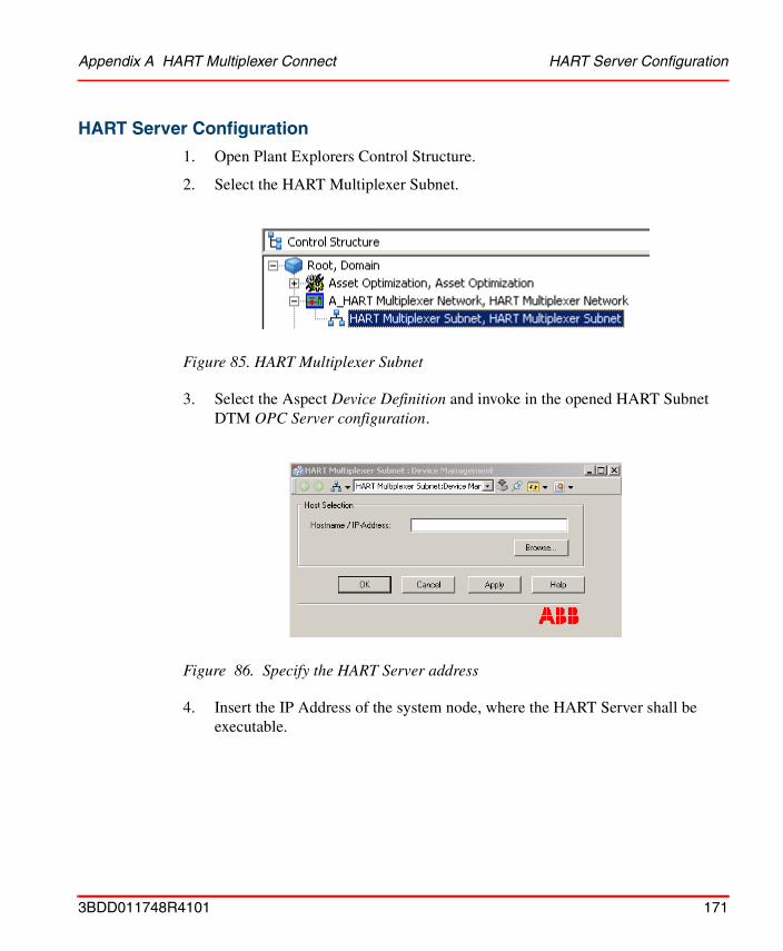
Appendix A HART Multiplexer Connect HART Server Configuration
HART Server Configuration
1. Open Plant Explorers Control Structure.
2. Select the HART Multiplexer Subnet.
3. Select the Aspect Device Definition and invoke in the opened HART Subnet DTM OPC Server configuration.
4. Insert the IP Address of the system node, where the HART Server shall be executable.
Figure 85. HART Multiplexer Subnet
Figure 86. Specify the HART Server address
3BDD011748R4101 171
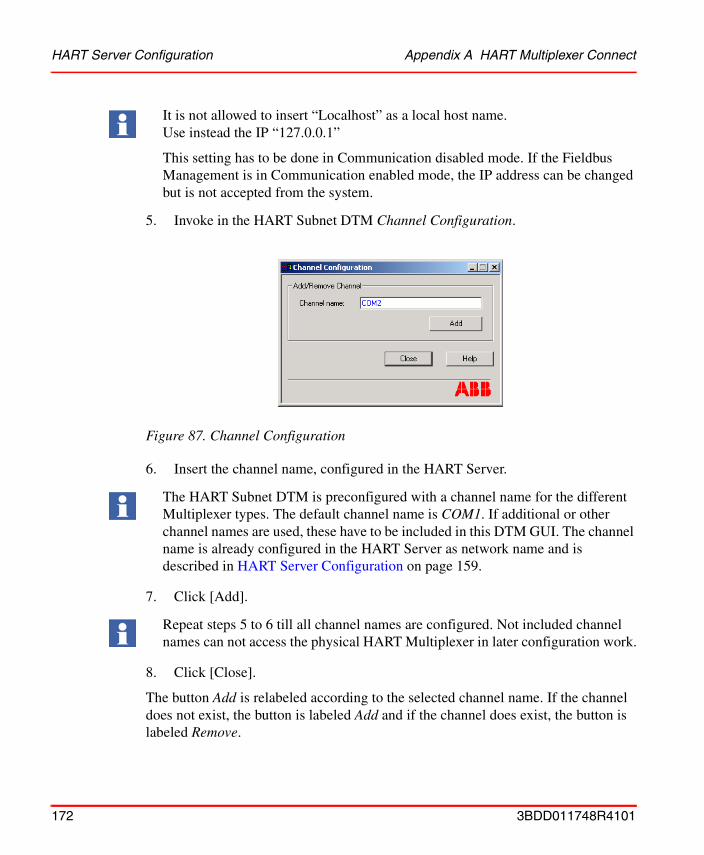
HART Server Configuration Appendix A HART Multiplexer Connect
5. Invoke in the HART Subnet DTM Channel Configuration.
6. Insert the channel name, configured in the HART Server.
7. Click [Add].
8. Click [Close].
The button Add is relabeled according to the selected channel name. If the channel does not exist, the button is labeled Add and if the channel does exist, the button is labeled Remove.
It is not allowed to insert “Localhost” as a local host name. Use instead the IP “127.0.0.1”
This setting has to be done in Communication disabled mode. If the Fieldbus Management is in Communication enabled mode, the IP address can be changed but is not accepted from the system.
Figure 87. Channel Configuration
The HART Subnet DTM is preconfigured with a channel name for the different Multiplexer types. The default channel name is COM1. If additional or other channel names are used, these have to be included in this DTM GUI. The channel name is already configured in the HART Server as network name and is described in HART Server Configuration on page 159.
Repeat steps 5 to 6 till all channel names are configured. Not included channel names can not access the physical HART Multiplexer in later configuration work.
172 3BDD011748R4101
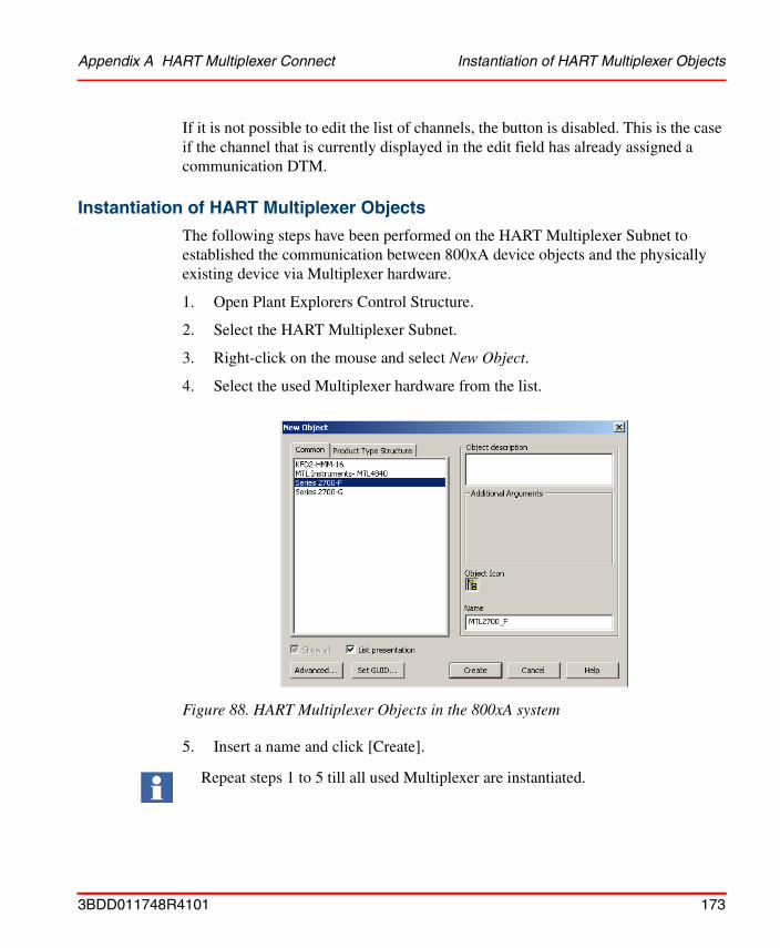
Appendix A HART Multiplexer Connect Instantiation of HART Multiplexer Objects
If it is not possible to edit the list of channels, the button is disabled. This is the case if the channel that is currently displayed in the edit field has already assigned a communication DTM.
Instantiation of HART Multiplexer Objects
The following steps have been performed on the HART Multiplexer Subnet to established the communication between 800xA device objects and the physically existing device via Multiplexer hardware.
1. Open Plant Explorers Control Structure.
2. Select the HART Multiplexer Subnet.
3. Right-click on the mouse and select New Object.
4. Select the used Multiplexer hardware from the list.
5. Insert a name and click [Create].
Figure 88. HART Multiplexer Objects in the 800xA system
Repeat steps 1 to 5 till all used Multiplexer are instantiated.
3BDD011748R4101 173
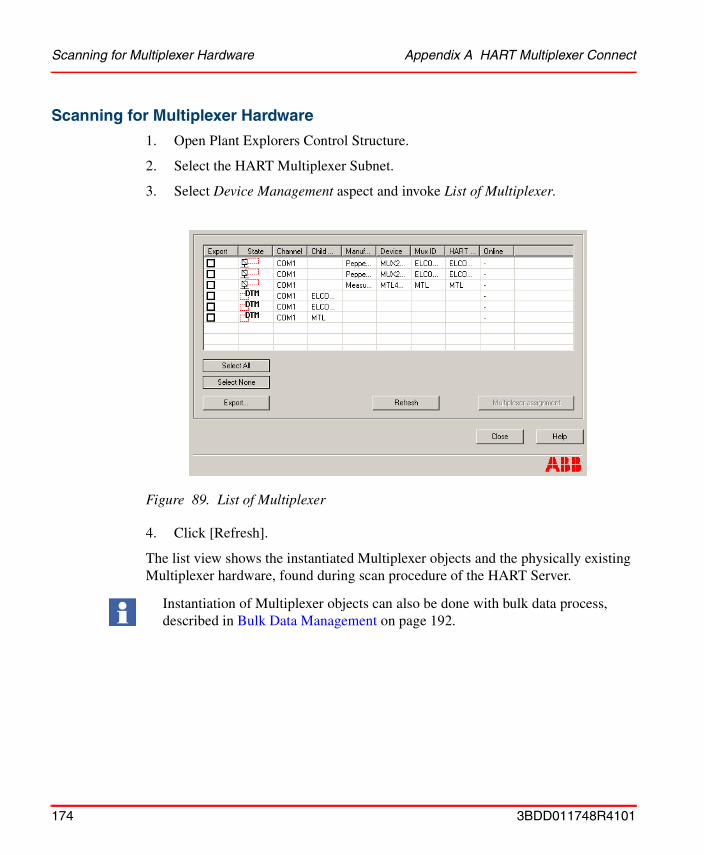
Scanning for Multiplexer Hardware Appendix A HART Multiplexer Connect
Scanning for Multiplexer Hardware
1. Open Plant Explorers Control Structure.
2. Select the HART Multiplexer Subnet.
3. Select Device Management aspect and invoke List of Multiplexer.
4. Click [Refresh].
The list view shows the instantiated Multiplexer objects and the physically existing Multiplexer hardware, found during scan procedure of the HART Server.
Figure 89. List of Multiplexer
Instantiation of Multiplexer objects can also be done with bulk data process, described in Bulk Data Management on page 192.
174 3BDD011748R4101
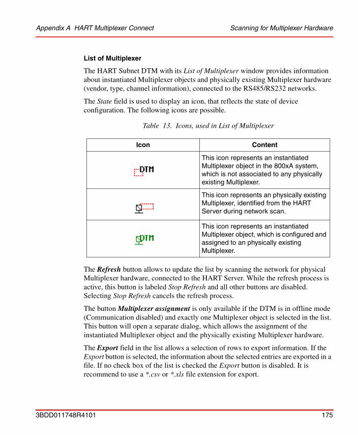
Appendix A HART Multiplexer Connect Scanning for Multiplexer Hardware
List of Multiplexer
The HART Subnet DTM with its List of Multiplexer window provides information about instantiated Multiplexer objects and physically existing Multiplexer hardware (vendor, type, channel information), connected to the RS485/RS232 networks.
The State field is used to display an icon, that reflects the state of device configuration. The following icons are possible.
The Refresh button allows to update the list by scanning the network for physical Multiplexer hardware, connected to the HART Server. While the refresh process is active, this button is labeled Stop Refresh and all other buttons are disabled. Selecting Stop Refresh cancels the refresh process.
The button Multiplexer assignment is only available if the DTM is in offline mode (Communication disabled) and exactly one Multiplexer object is selected in the list. This button will open a separate dialog, which allows the assignment of the instantiated Multiplexer object and the physically existing Multiplexer hardware.
The Export field in the list allows a selection of rows to export information. If the Export button is selected, the information about the selected entries are exported in a file. If no check box of the list is checked the Export button is disabled. It is recommend to use a *.csv or *.xls file extension for export.
Table 13. Icons, used in List of Multiplexer
Icon Content
This icon represents an instantiated Multiplexer object in the 800xA system, which is not associated to any physically existing Multiplexer.
This icon represents an physically existing Multiplexer, identified from the HART Server during network scan.
This icon represents an instantiated Multiplexer object, which is configured and assigned to an physically existing Multiplexer.
3BDD011748R4101 175
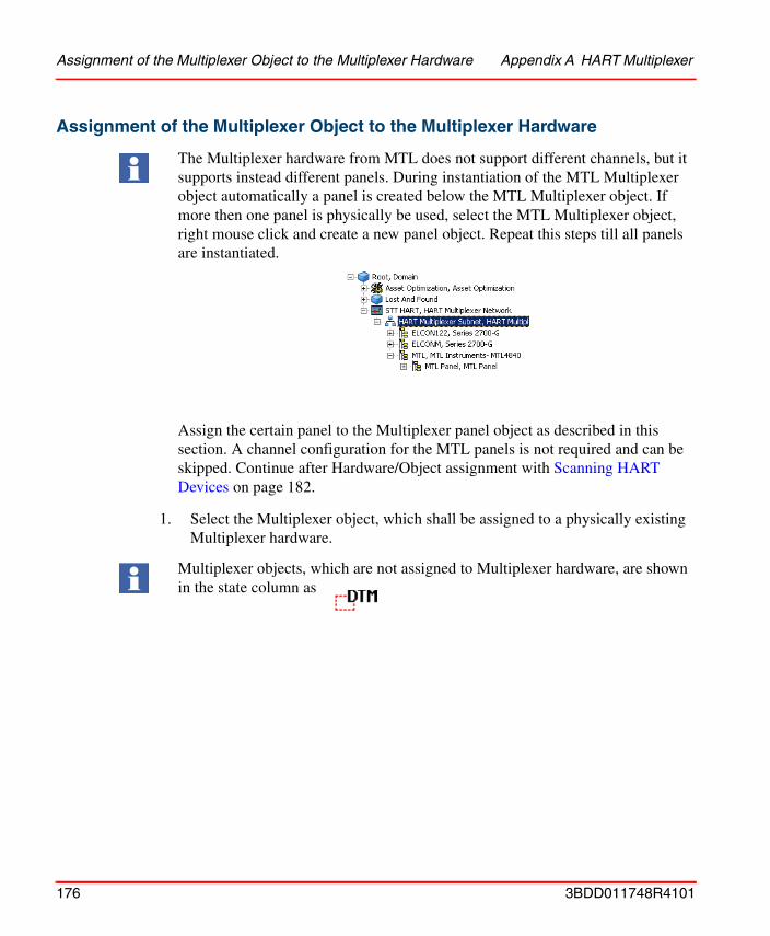
Assignment of the Multiplexer Object to the Multiplexer Hardware Appendix A HART Multiplexer
Assignment of the Multiplexer Object to the Multiplexer Hardware
1. Select the Multiplexer object, which shall be assigned to a physically existing Multiplexer hardware.
The Multiplexer hardware from MTL does not support different channels, but it supports instead different panels. During instantiation of the MTL Multiplexer object automatically a panel is created below the MTL Multiplexer object. If more then one panel is physically be used, select the MTL Multiplexer object, right mouse click and create a new panel object. Repeat this steps till all panels are instantiated.
Assign the certain panel to the Multiplexer panel object as described in this section. A channel configuration for the MTL panels is not required and can be skipped. Continue after Hardware/Object assignment with Scanning HART Devices on page 182.
Multiplexer objects, which are not assigned to Multiplexer hardware, are shown in the state column as
176 3BDD011748R4101
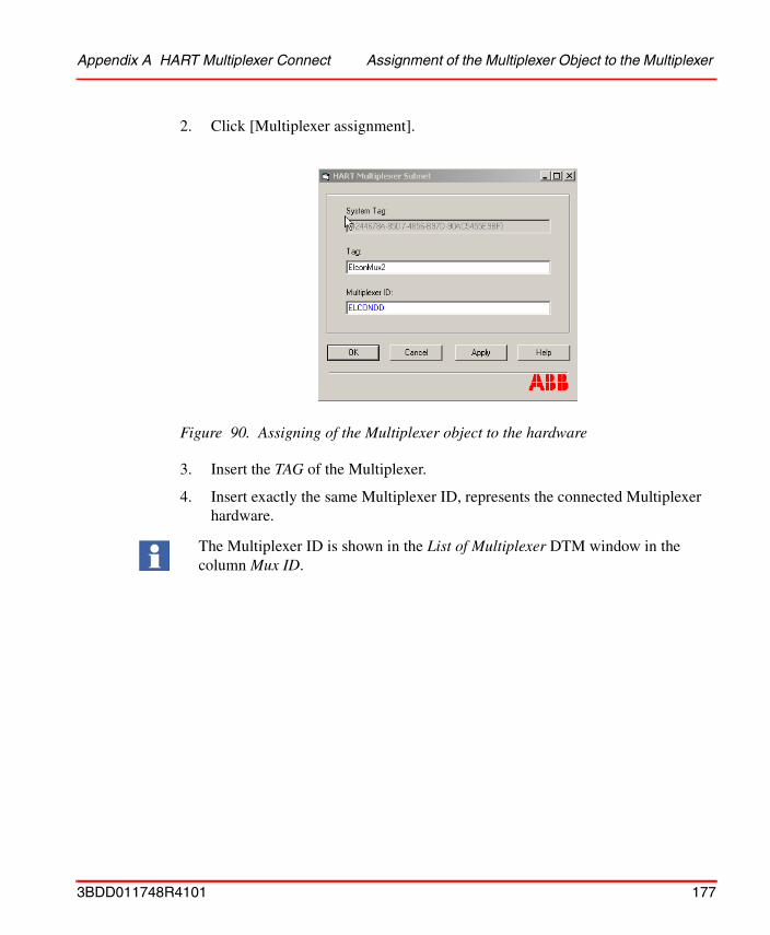
Appendix A HART Multiplexer Connect Assignment of the Multiplexer Object to the Multiplexer
2. Click [Multiplexer assignment].
3. Insert the TAG of the Multiplexer.
4. Insert exactly the same Multiplexer ID, represents the connected Multiplexer hardware.
Figure 90. Assigning of the Multiplexer object to the hardware
The Multiplexer ID is shown in the List of Multiplexer DTM window in the column Mux ID.
3BDD011748R4101 177
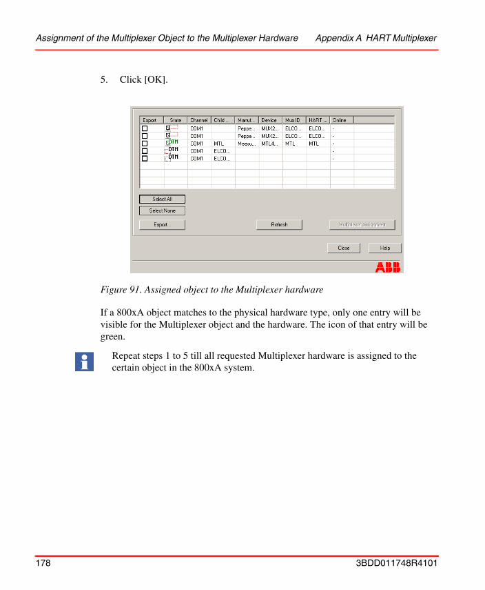
Assignment of the Multiplexer Object to the Multiplexer Hardware Appendix A HART Multiplexer
5. Click [OK].
If a 800xA object matches to the physical hardware type, only one entry will be visible for the Multiplexer object and the hardware. The icon of that entry will be green.
Figure 91. Assigned object to the Multiplexer hardware
Repeat steps 1 to 5 till all requested Multiplexer hardware is assigned to the certain object in the 800xA system.
178 3BDD011748R4101
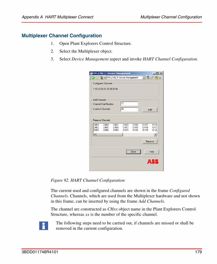
Appendix A HART Multiplexer Connect Multiplexer Channel Configuration
Multiplexer Channel Configuration
1. Open Plant Explorers Control Structure.
2. Select the Multiplexer object.
3. Select Device Management aspect and invoke HART Channel Configuration.
The current used and configured channels are shown in the frame Configured Channels. Channels, which are used from the Multiplexer hardware and not shown in this frame, can be inserted by using the frame Add Channels.
The channel are constructed as CHxx object name in the Plant Explorers Control Structure, whereas xx is the number of the specific channel.
Figure 92. HART Channel Configuration
The following steps need to be carried out, if channels are missed or shall be removed in the current configuration.
3BDD011748R4101 179
Multiplexer Channel Configuration Appendix A HART Multiplexer Connect
Add new Channels
The frame Add Channels allows to add further used channels of the Multiplexer, which are not configured yet.
1. Insert the Channel Start Number of the channels, which shall be added to the configuration.
Channel Start Number allows to define the first missed channel of the Multiplexer hardware.
2. Insert the increment number of channels in the field Count of Channels.
The entered number in the Count of Channels field is the amount of used channels.
Remove Channels
The frame Remove channels allows to delete those channels, which are not used from the Multiplexer hardware. Multiple selection is possible. Clicking the Remove button results in deleting the selected channels.
Example: The first missed channel is number 17. Enter number 17 in the name box.
Example:The first missed channel is number 17. The last missed channel is number 19. Enter the number 3 in the Count of Channels field. Channel 17, 18 and 19 are added to the configuration.
Channel configuration optimizes the performance of the Multiplexer scan rate. Therefor only the physically used channels shall be configured.
The add and remove functionality of the HART Channel Configuration window is write protected if HART devices are already associated to any HART channel of the Multiplexer object or if the HART Multiplexer network is in Communication enabled mode.
A channel configuration is not possible till all inserted device objects below the Multiplexer object are deleted.
180 3BDD011748R4101
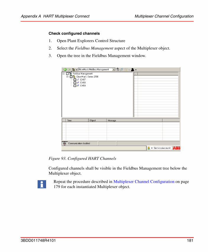
Appendix A HART Multiplexer Connect Multiplexer Channel Configuration
Check configured channels
1. Open Plant Explorers Control Structure
2. Select the Fieldbus Management aspect of the Multiplexer object.
3. Open the tree in the Fieldbus Management window.
Configured channels shall be visible in the Fieldbus Management tree below the Multiplexer object.
Figure 93. Configured HART Channels
Repeat the procedure described in Multiplexer Channel Configuration on page 179 for each instantiated Multiplexer object.
3BDD011748R4101 181
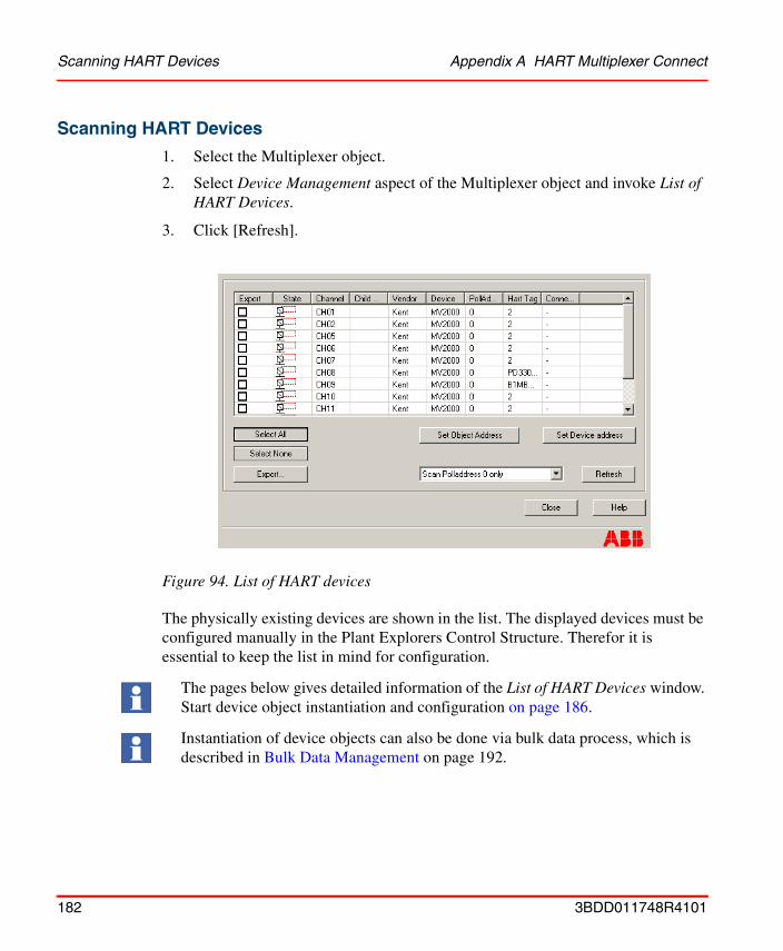
Scanning HART Devices Appendix A HART Multiplexer Connect
Scanning HART Devices
1. Select the Multiplexer object.
2. Select Device Management aspect of the Multiplexer object and invoke List of HART Devices.
3. Click [Refresh].
The physically existing devices are shown in the list. The displayed devices must be configured manually in the Plant Explorers Control Structure. Therefor it is essential to keep the list in mind for configuration.
Figure 94. List of HART devices
The pages below gives detailed information of the List of HART Devices window. Start device object instantiation and configuration on page 186.
Instantiation of device objects can also be done via bulk data process, which is described in Bulk Data Management on page 192.
182 3BDD011748R4101
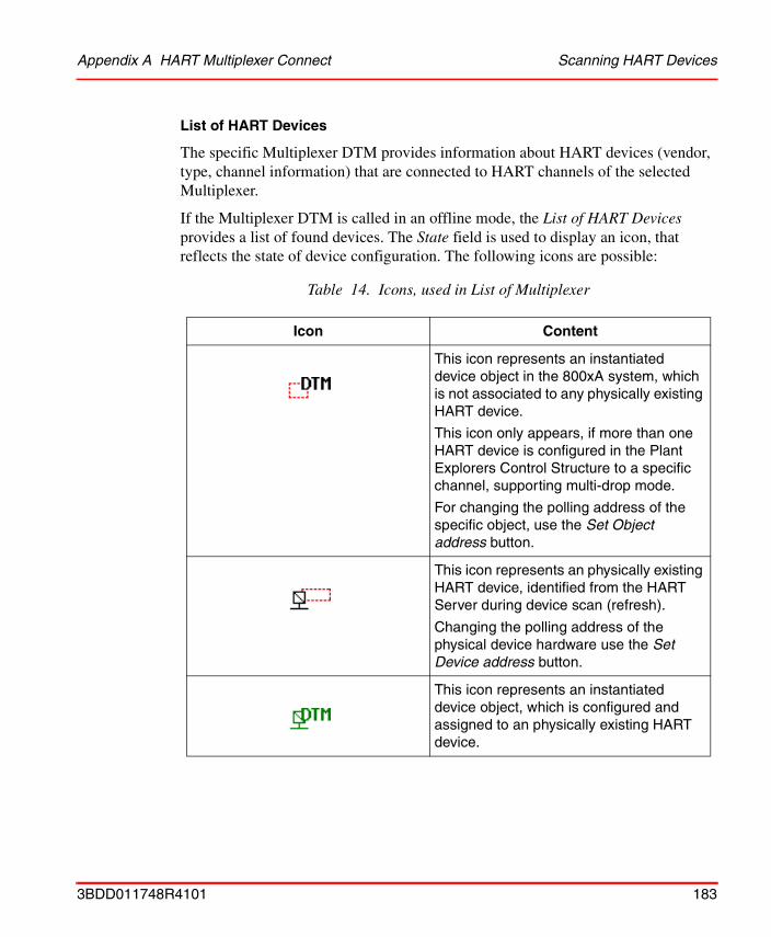
Appendix A HART Multiplexer Connect Scanning HART Devices
List of HART Devices
The specific Multiplexer DTM provides information about HART devices (vendor, type, channel information) that are connected to HART channels of the selected Multiplexer.
If the Multiplexer DTM is called in an offline mode, the List of HART Devices provides a list of found devices. The State field is used to display an icon, that reflects the state of device configuration. The following icons are possible:
Table 14. Icons, used in List of Multiplexer
Icon Content
This icon represents an instantiated device object in the 800xA system, which is not associated to any physically existing HART device.
This icon only appears, if more than one HART device is configured in the Plant Explorers Control Structure to a specific channel, supporting multi-drop mode.
For changing the polling address of the specific object, use the Set Object address button.
This icon represents an physically existing HART device, identified from the HART Server during device scan (refresh).
Changing the polling address of the physical device hardware use the Set Device address button.
This icon represents an instantiated device object, which is configured and assigned to an physically existing HART device.
3BDD011748R4101 183
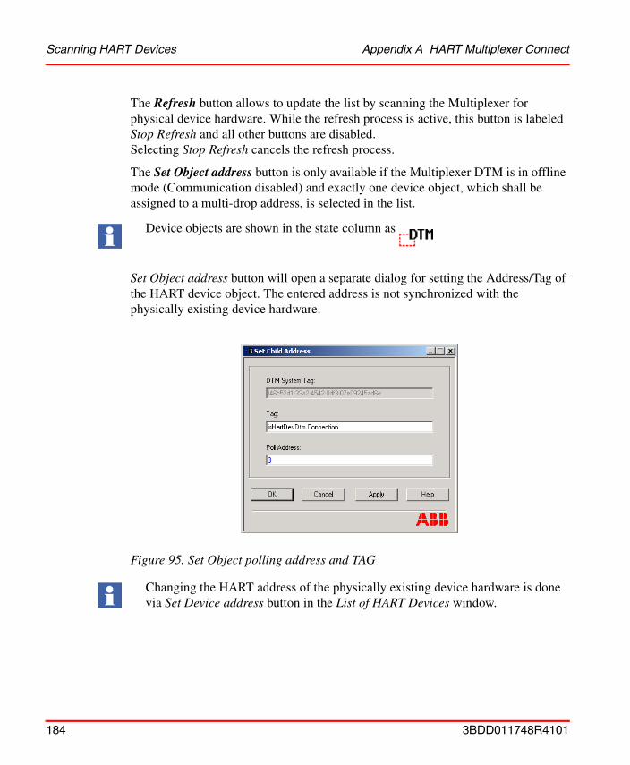
Scanning HART Devices Appendix A HART Multiplexer Connect
The Refresh button allows to update the list by scanning the Multiplexer for physical device hardware. While the refresh process is active, this button is labeled Stop Refresh and all other buttons are disabled. Selecting Stop Refresh cancels the refresh process.
The Set Object address button is only available if the Multiplexer DTM is in offline mode (Communication disabled) and exactly one device object, which shall be assigned to a multi-drop address, is selected in the list.
Set Object address button will open a separate dialog for setting the Address/Tag of the HART device object. The entered address is not synchronized with the physically existing device hardware.
Device objects are shown in the state column as
Figure 95. Set Object polling address and TAG
Changing the HART address of the physically existing device hardware is done via Set Device address button in the List of HART Devices window.
184 3BDD011748R4101

Appendix A HART Multiplexer Connect Scanning HART Devices
The Set Device address button is only available if the DTM is in online mode (Communication enabled) and exactly one physical HART device, which shall be set to a poll address, is selected in the list.
Set Device address button will open a separate dialog for setting the poll address of the physical HART device. The entered address is not synchronized with the device object.
The Export field in the list allows a selection of rows for export information. If the Export button is selected, the information about the selected entries are exported in an excel file. If no check box of the list is checked the Export button is disabled. It is recommend to use a *.csv or *.xls file extension for export.
Use Select all button, if the export file shall contain the complete list of HART devices, shown in the window. All devices and objects are checked for export.
The Deselect all button removes all check marks of the selected objects.
There is a combobox for choosing the kind of scanning. Either only address 0 is scanned or the channels are polled from 0 to 15.
Physical HART devices are shown in the state column as
Figure 96. Set Device address
Changing the address of the device object is done via Set Object address button in the List of HART Devices window.
3BDD011748R4101 185
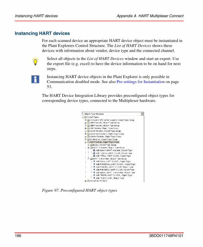
Instancing HART devices Appendix A HART Multiplexer Connect
Instancing HART devices
For each scanned device an appropriate HART device object must be instantiated in the Plant Explorers Control Structure. The List of HART Devices shows these devices with information about vendor, device type and the connected channel.
The HART Device Integration Library provides preconfigured object types for corresponding device types, connected to the Multiplexer hardware.
Select all objects in the List of HART Devices window and start an export. Use the export file (e.g. excel) to have the device information to be on hand for next steps.
Instancing HART device objects in the Plant Explorer is only possible in Communication disabled mode. See also Pre-settings for Instantiation on page 53.
Figure 97. Preconfigured HART object types
186 3BDD011748R4101

Appendix A HART Multiplexer Connect Instancing HART devices
1. Open Plant Explorers Control Structure.
2. Select the Multiplexer object below which the HART device object will be placed, e.g. Elcon’s Series 2700.
3. Click with the right mouse button to open the context menu.
4. Select New Object in the context menu.
5. Open the Field Device folder in the new window and select the required device object.
For HART, object types are stored inside the Field Devices catalog. The object types in the Basics, Object Type Group catalog are generic object types, which are not designed for direct use! Please use device types from HART Actuators and HART Transmitter Object Type Groups instead!
The HART Device Integration Library include HART Device Objects, prepared for use of vendor specific DTM. In this case the DTM has to be installed manually before instantiation. For a description of how to install specific DTMs, see Installation of Device Type Manager (DTM) on page 33.
Vendor specific DTMs sometimes include a license mechanism to run the DTM without limitations. Only the DTM software is part of the Device Integration Package, the specific license of a DTM not. The DTM license has to be ordered separately from the DTM vendor. Licenses for a DTM are not included in the 800xA licensing.
Figure 98. Creating a new device object
If the required device object is not available in the device object list, the generic HART object can be used.
3BDD011748R4101 187
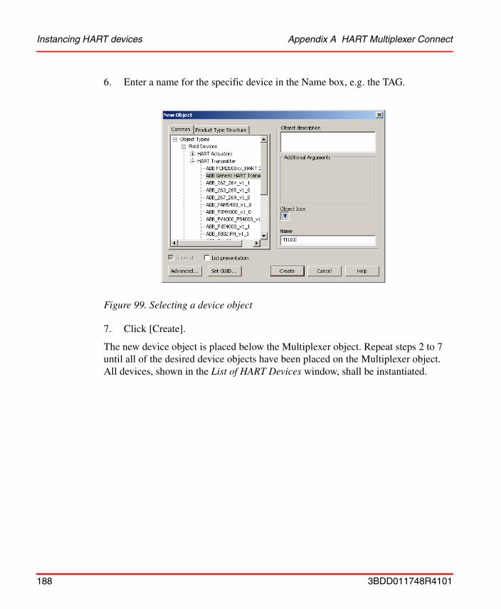
Instancing HART devices Appendix A HART Multiplexer Connect
6. Enter a name for the specific device in the Name box, e.g. the TAG.
7. Click [Create].
The new device object is placed below the Multiplexer object. Repeat steps 2 to 7 until all of the desired device objects have been placed on the Multiplexer object. All devices, shown in the List of HART Devices window, shall be instantiated.
Figure 99. Selecting a device object
188 3BDD011748R4101

Appendix A HART Multiplexer Connect Instancing HART devices
Channel allocation on Multiplexer object
The following operations must be carried out to assign the HART device objects to the Multiplexer channels:
1. Open Plant Explorers Control Structure.
2. Select the Fieldbus Management aspect on the Multiplexer object type, e.g. Elcon’s Series 2700.
3. The user interface of the Fieldbus Builder PROFIBUS/HART appears in the main window. The Fieldbus Builder PROFIBUS/HART copies the fieldbus tree from the Control Structure to its fieldbus tree in the main window. To improve performance levels, the partial tree is not copied in its entirety.
4. Click "+" to open the next level of the partial tree.
5. All positioned field devices, together with the channel information from the Multiplexer objects, now appear in the partial tree.
Figure 100. Fieldbus Management view
3BDD011748R4101 189
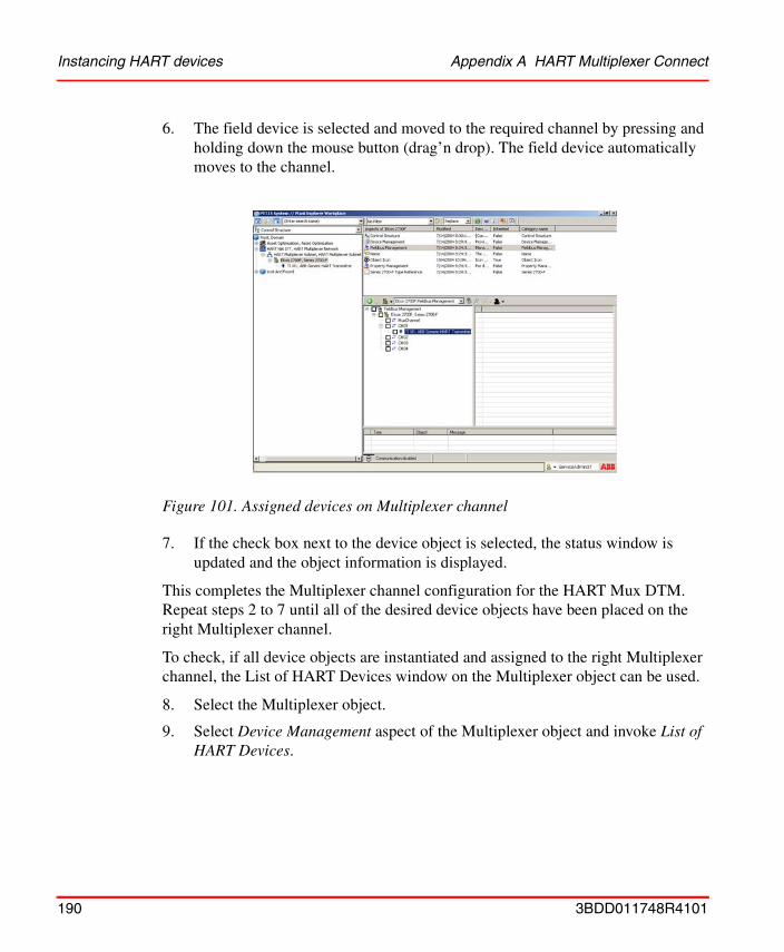
Instancing HART devices Appendix A HART Multiplexer Connect
6. The field device is selected and moved to the required channel by pressing and holding down the mouse button (drag’n drop). The field device automatically moves to the channel.
7. If the check box next to the device object is selected, the status window is updated and the object information is displayed.
This completes the Multiplexer channel configuration for the HART Mux DTM. Repeat steps 2 to 7 until all of the desired device objects have been placed on the right Multiplexer channel.
To check, if all device objects are instantiated and assigned to the right Multiplexer channel, the List of HART Devices window on the Multiplexer object can be used.
8. Select the Multiplexer object.
9. Select Device Management aspect of the Multiplexer object and invoke List of HART Devices.
Figure 101. Assigned devices on Multiplexer channel
190 3BDD011748R4101
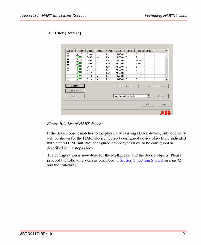
Appendix A HART Multiplexer Connect Instancing HART devices
10. Click [Refresh].
If the device object matches to the physically existing HART device, only one entry will be shown for the HART device. Correct configured device objects are indicated with green DTM sign. Not configured device types have to be configured as described in the steps above.
The configuration is now done for the Multiplexer and the device objects. Please proceed the following steps as described in Section 2, Getting Started on page 65 and the following.
Figure 102. List of HART devices
3BDD011748R4101 191
Bulk Data Management Appendix A HART Multiplexer Connect
Bulk Data ManagementThis section describes the usage of Bulk Data Manager for device integration. Bulk Data Manager is a component of the 800xA Engineering Workplace, composed of Microsoft® Excel and a set of Excel Add-Ins that integrate Microsoft Excel into Engineering Workplace.
Excel spreadsheets together with Bulk Data Management enable the user to save manually object by object instantiation work. The user can easily re-use a typical solution built either as object type or as object instance using the spreadsheet based configuration functions of Bulk Data Manager to populate a plant model in the system.
The basic functionality of Bulk Data Management allows to configure a worksheet for reading out and writing back the properties of aspects of objects.
The user configures the worksheet by dropping in the aspects from Plant Explorer and selecting the aspect properties of their interest. The data contents of this worksheet can be acquired by dropping in the objects of interest from Plant Explorer. Each row holds the data for one object. The properties of the corresponding aspects of the dropped in objects are shown in the configured columns.
This worksheet also allows to create new objects from object types or from already existing object instances and to create the placement of the objects in structures.
For example to duplicate a substructure of objects you have to copy the area of rows corresponding to the objects of interest in the worksheet using well-known Excel functionality, you edit the names of the new objects and the data of other properties and save the changed spreadsheet contents to the system by executing a Save All Objects command.
Detailed information about Bulk Data Manager is described in Industrial IT 800xA - Engineering, Engineering Workplace, Basic Engineering Functions Reference (3BDS011223).
If you use the Bulk Data Manager to save data to Industrial IT applications in an operating environment make sure that this does not conflict with secure plant operation.
192 3BDD011748R4101
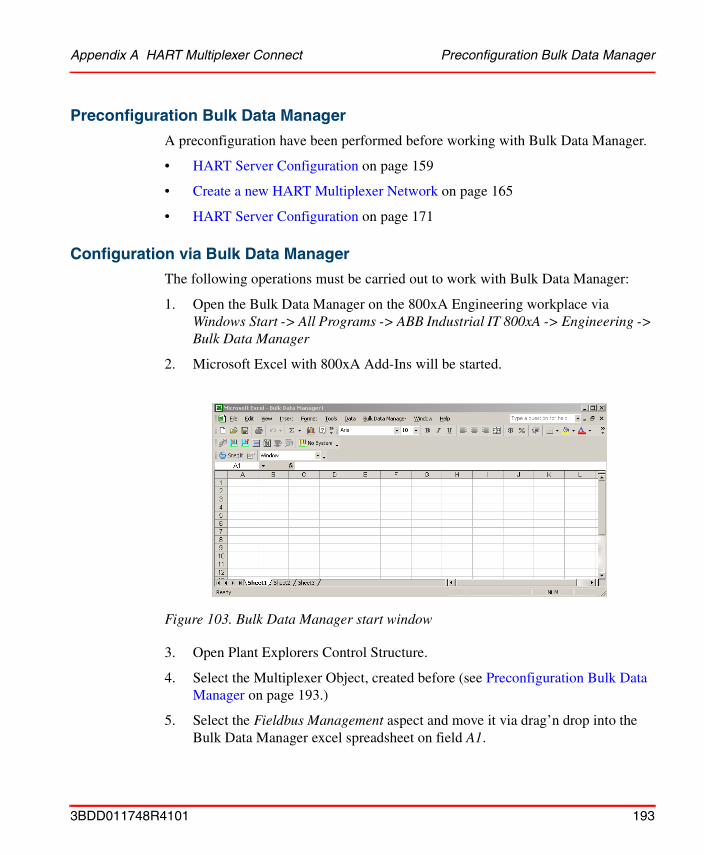
Appendix A HART Multiplexer Connect Preconfiguration Bulk Data Manager
Preconfiguration Bulk Data Manager
A preconfiguration have been performed before working with Bulk Data Manager.
• HART Server Configuration on page 159
• Create a new HART Multiplexer Network on page 165
• HART Server Configuration on page 171
Configuration via Bulk Data Manager
The following operations must be carried out to work with Bulk Data Manager:
1. Open the Bulk Data Manager on the 800xA Engineering workplace via Windows Start -> All Programs -> ABB Industrial IT 800xA -> Engineering -> Bulk Data Manager
2. Microsoft Excel with 800xA Add-Ins will be started.
3. Open Plant Explorers Control Structure.
4. Select the Multiplexer Object, created before (see Preconfiguration Bulk Data Manager on page 193.)
5. Select the Fieldbus Management aspect and move it via drag’n drop into the Bulk Data Manager excel spreadsheet on field A1.
Figure 103. Bulk Data Manager start window
3BDD011748R4101 193
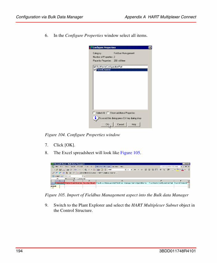
Configuration via Bulk Data Manager Appendix A HART Multiplexer Connect
6. In the Configure Properties window select all items.
7. Click [OK].
8. The Excel spreadsheet will look like Figure 105.
9. Switch to the Plant Explorer and select the HART Multiplexer Subnet object in the Control Structure.
Figure 104. Configure Properties window
Figure 105. Import of Fieldbus Management aspect into the Bulk data Manager
194 3BDD011748R4101
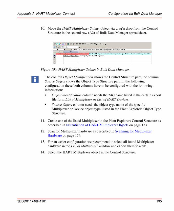
Appendix A HART Multiplexer Connect Configuration via Bulk Data Manager
10. Move the HART Multiplexer Subnet object via drag’n drop from the Control Structure in the second row (A2) of Bulk Data Manager spreadsheet.
11. Create one of the listed Multiplexer in the Plant Explorers Control Structure as described in Instantiation of HART Multiplexer Objects on page 173.
12. Scan for Multiplexer hardware as described in Scanning for Multiplexer Hardware on page 174.
13. For an easier configuration we recommend to select all found Multiplexer hardware in the List of Multiplexer window and export them to a file.
14. Select the HART Multiplexer object in the Control Structure.
Figure 106. HART Multiplexer Subnet in Bulk Data Manager
The column Object Identification shows the Control Structure part, the column Source Object shows the Object Type Structure part. In the following configuration these both columns have to be configured with the following information:
• Object Identification column needs the TAG name listed in the certain export file form List of Multiplexer or List of HART Devices.
• Source Object column needs the object type name of the specific Multiplexer or Device object type, listed in the Plant Explorers Object Type Structure.
3BDD011748R4101 195
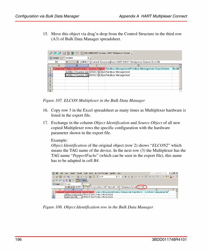
Configuration via Bulk Data Manager Appendix A HART Multiplexer Connect
15. Move this object via drag’n drop from the Control Structure in the third row (A3) of Bulk Data Manager spreadsheet.
16. Copy row 3 in the Excel spreadsheet as many times as Multiplexer hardware is listed in the export file.
17. Exchange in the column Object Identification and Source Object of all new copied Multiplexer rows the specific configuration with the hardware parameter shown in the export file.
Example:Object Identification of the original object (row 2) shows “ELCON2” which means the TAG name of the device. In the next row (3) the Multiplexer has the TAG name “PepperlFuchs” (which can be seen in the export file), this name has to be adapted in cell B4.
Figure 107. ELCON Multiplexer in the Bulk Data Manager
Figure 108. Object Identification row in the Bulk Data Manager
196 3BDD011748R4101
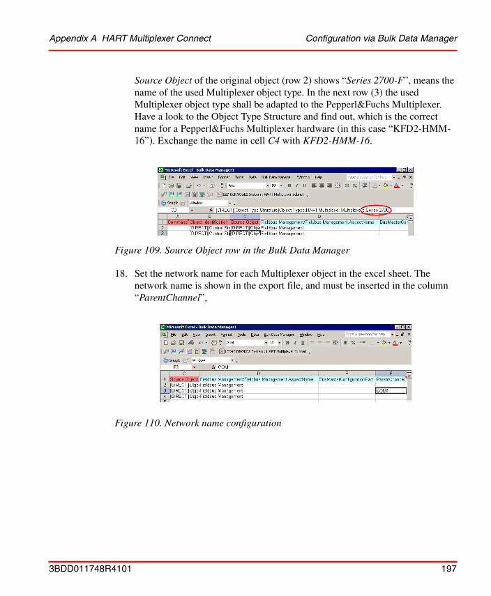
Appendix A HART Multiplexer Connect Configuration via Bulk Data Manager
Source Object of the original object (row 2) shows “Series 2700-F”, means the name of the used Multiplexer object type. In the next row (3) the used Multiplexer object type shall be adapted to the Pepperl&Fuchs Multiplexer. Have a look to the Object Type Structure and find out, which is the correct name for a Pepperl&Fuchs Multiplexer hardware (in this case “KFD2-HMM-16”). Exchange the name in cell C4 with KFD2-HMM-16.
18. Set the network name for each Multiplexer object in the excel sheet. The network name is shown in the export file, and must be inserted in the column “ParentChannel”,
Figure 109. Source Object row in the Bulk Data Manager
Figure 110. Network name configuration
3BDD011748R4101 197
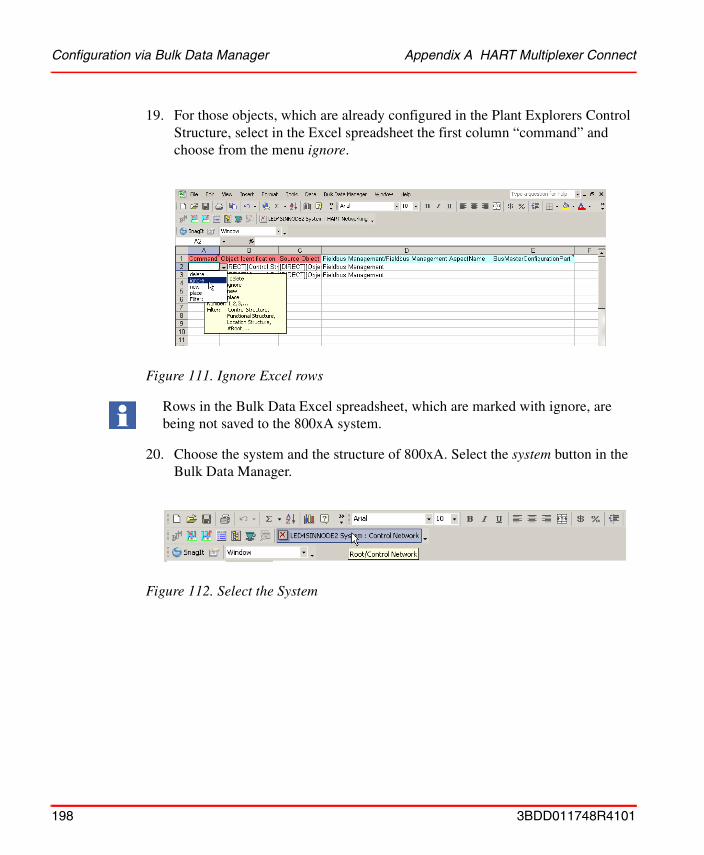
Configuration via Bulk Data Manager Appendix A HART Multiplexer Connect
19. For those objects, which are already configured in the Plant Explorers Control Structure, select in the Excel spreadsheet the first column “command” and choose from the menu ignore.
20. Choose the system and the structure of 800xA. Select the system button in the Bulk Data Manager.
Figure 111. Ignore Excel rows
Rows in the Bulk Data Excel spreadsheet, which are marked with ignore, are being not saved to the 800xA system.
Figure 112. Select the System
198 3BDD011748R4101
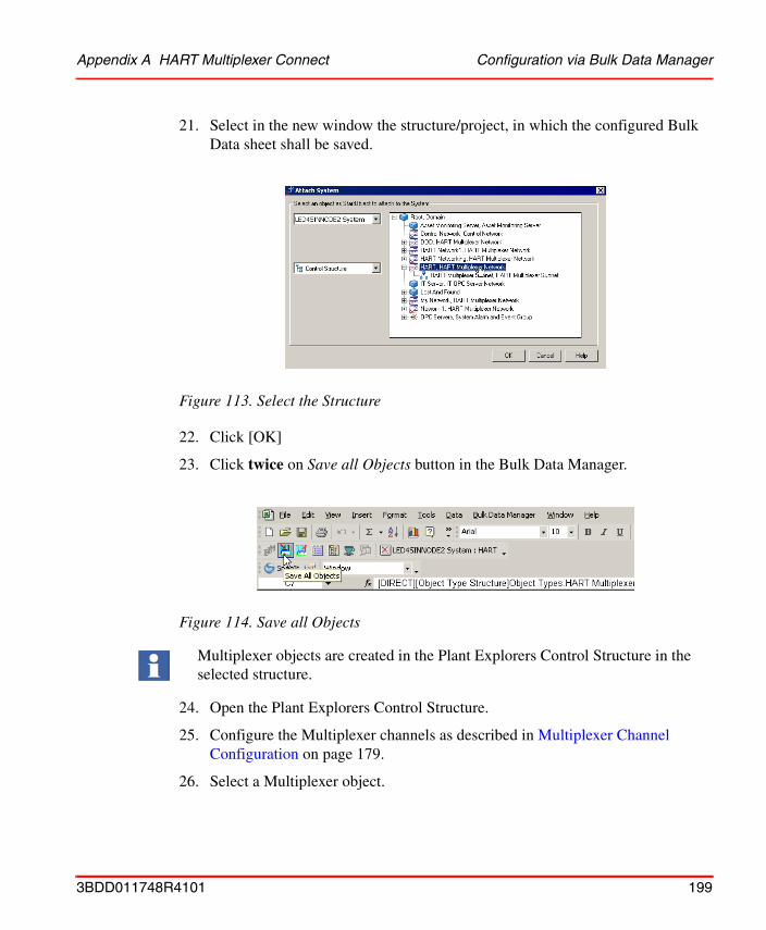
Appendix A HART Multiplexer Connect Configuration via Bulk Data Manager
21. Select in the new window the structure/project, in which the configured Bulk Data sheet shall be saved.
22. Click [OK]
23. Click twice on Save all Objects button in the Bulk Data Manager.
24. Open the Plant Explorers Control Structure.
25. Configure the Multiplexer channels as described in Multiplexer Channel Configuration on page 179.
26. Select a Multiplexer object.
Figure 113. Select the Structure
Figure 114. Save all Objects
Multiplexer objects are created in the Plant Explorers Control Structure in the selected structure.
3BDD011748R4101 199
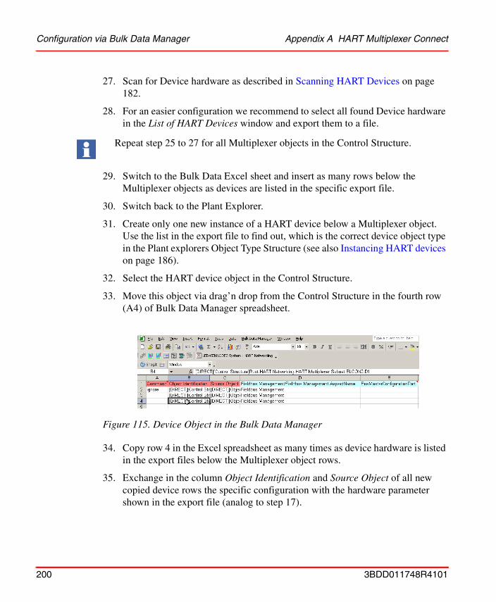
Configuration via Bulk Data Manager Appendix A HART Multiplexer Connect
27. Scan for Device hardware as described in Scanning HART Devices on page 182.
28. For an easier configuration we recommend to select all found Device hardware in the List of HART Devices window and export them to a file.
29. Switch to the Bulk Data Excel sheet and insert as many rows below the Multiplexer objects as devices are listed in the specific export file.
30. Switch back to the Plant Explorer.
31. Create only one new instance of a HART device below a Multiplexer object. Use the list in the export file to find out, which is the correct device object type in the Plant explorers Object Type Structure (see also Instancing HART devices on page 186).
32. Select the HART device object in the Control Structure.
33. Move this object via drag’n drop from the Control Structure in the fourth row (A4) of Bulk Data Manager spreadsheet.
34. Copy row 4 in the Excel spreadsheet as many times as device hardware is listed in the export files below the Multiplexer object rows.
35. Exchange in the column Object Identification and Source Object of all new copied device rows the specific configuration with the hardware parameter shown in the export file (analog to step 17).
Repeat step 25 to 27 for all Multiplexer objects in the Control Structure.
Figure 115. Device Object in the Bulk Data Manager
200 3BDD011748R4101
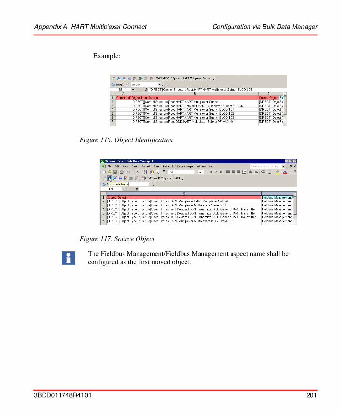
Appendix A HART Multiplexer Connect Configuration via Bulk Data Manager
Example:
Figure 116. Object Identification
Figure 117. Source Object
The Fieldbus Management/Fieldbus Management aspect name shall be configured as the first moved object.
3BDD011748R4101 201
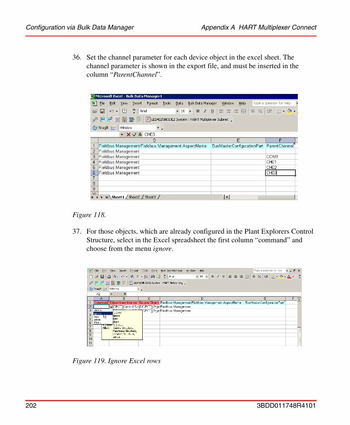
Configuration via Bulk Data Manager Appendix A HART Multiplexer Connect
36. Set the channel parameter for each device object in the excel sheet. The channel parameter is shown in the export file, and must be inserted in the column “ParentChannel”.
37. For those objects, which are already configured in the Plant Explorers Control Structure, select in the Excel spreadsheet the first column “command” and choose from the menu ignore.
Figure 118.
Figure 119. Ignore Excel rows
202 3BDD011748R4101
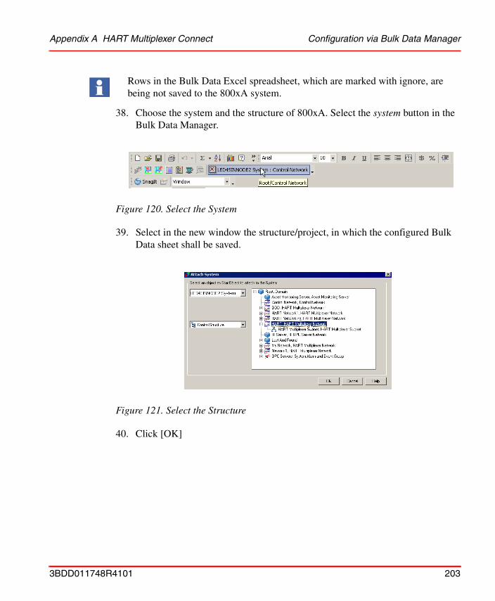
Appendix A HART Multiplexer Connect Configuration via Bulk Data Manager
38. Choose the system and the structure of 800xA. Select the system button in the Bulk Data Manager.
39. Select in the new window the structure/project, in which the configured Bulk Data sheet shall be saved.
40. Click [OK]
Rows in the Bulk Data Excel spreadsheet, which are marked with ignore, are being not saved to the 800xA system.
Figure 120. Select the System
Figure 121. Select the Structure
3BDD011748R4101 203
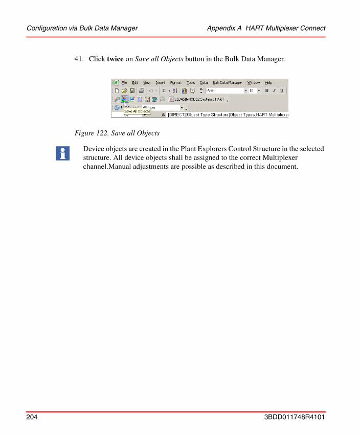
Configuration via Bulk Data Manager Appendix A HART Multiplexer Connect
41. Click twice on Save all Objects button in the Bulk Data Manager.
Figure 122. Save all Objects
Device objects are created in the Plant Explorers Control Structure in the selected structure. All device objects shall be assigned to the correct Multiplexer channel.Manual adjustments are possible as described in this document.
204 3BDD011748R4101
Appendix B Fieldbus Builder Library Wizard
Fieldbus Builder Library WizardThe Fieldbus Builder Library Wizard can be used to create user-defined device object types in the Object Type Structure, which are not yet part of the Device Integration.
This tool cannot be executed directly from the 800xA system and must be started manually from the Windows Start menu.-> Start -> All Programs -> ABB Industrial IT 800xA -> DevMgmt - HART -> FBB Library Wizard
Only device type objects in the 800xA system created in accordance with the instructions in this section and based on generic device library templates are permitted.
Manual created object types can not be automatically updated with object types included in the Device Integration Library. Also new features coming with the Device Integration are not assigned to these self-made object types.
The templates are based on the Basic HART DTM, which can be used on all HART field devices.
Mainly the Fieldbus Builder Library Wizard is a development tool for creating object types. Object types generated in this way have not been tested against the 800xA system and may affect the operability of the system.
The new object types may be used for tests as well as for developing specific object types to be added to the device library.
ABB cannot guarantee an operable 800xA system if device object types that have not been tested are used in the system. Please contact the Device Integration Center if you wish to add devices to the device library. Additional information can be found in the Section 5, HART Device Integration Library.
3BDD011748R4101 205

Creating New Objects for HART Field Devices Appendix B Fieldbus Builder Library Wizard
Creating New Objects for HART Field Devices
New object types can be extended in two ways in the Object Type Structure:
• Using templates
• Using existing object types
Two predefined templates are available:
• Generic HART Actuator with assigned Basic HART DTM
• Generic HART Transmitter with assigned Basic HART DTM
The templates are located in the following structure:
Object Type Structure -> Object Types -> Field Devices -> Basics -> DTM Templates
Please follow the sequence below when creating a new object for a new HART field device:
The use and modification of existing object types is only permitted for development and test purposes. In terms of software, the templates are only suitable for test and development. We recommend that the existing templates installed with the Fieldbus Builder Library Wizard are used for creating new objects.
206 3BDD011748R4101
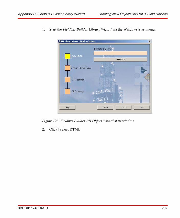
Appendix B Fieldbus Builder Library Wizard Creating New Objects for HART Field Devices
1. Start the Fieldbus Builder Library Wizard via the Windows Start menu.
2. Click [Select DTM].
Figure 123. Fieldbus Builder PH Object Wizard start window
3BDD011748R4101 207
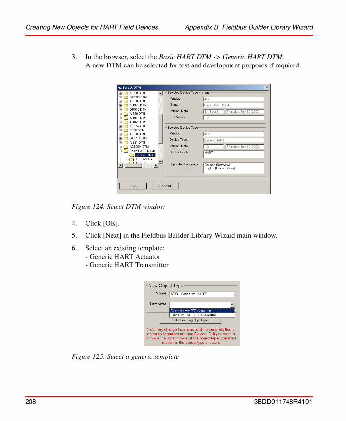
Creating New Objects for HART Field Devices Appendix B Fieldbus Builder Library Wizard
3. In the browser, select the Basic HART DTM -> Generic HART DTM.A new DTM can be selected for test and development purposes if required.
4. Click [OK].
5. Click [Next] in the Fieldbus Builder Library Wizard main window.
6. Select an existing template: - Generic HART Actuator- Generic HART Transmitter
Figure 124. Select DTM window
Figure 125. Select a generic template
208 3BDD011748R4101
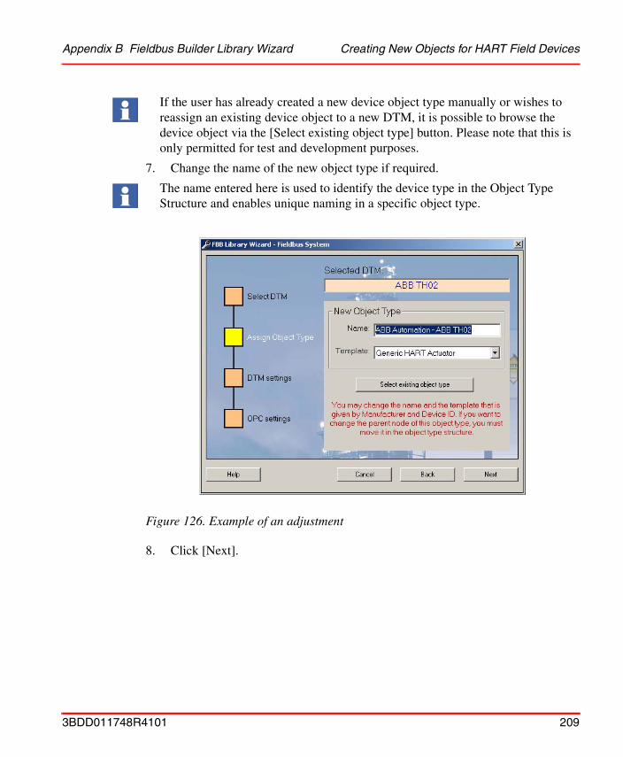
Appendix B Fieldbus Builder Library Wizard Creating New Objects for HART Field Devices
7. Change the name of the new object type if required.
8. Click [Next].
If the user has already created a new device object type manually or wishes to reassign an existing device object to a new DTM, it is possible to browse the device object via the [Select existing object type] button. Please note that this is only permitted for test and development purposes.
The name entered here is used to identify the device type in the Object Type Structure and enables unique naming in a specific object type.
Figure 126. Example of an adjustment
3BDD011748R4101 209

Creating New Objects for HART Field Devices Appendix B Fieldbus Builder Library Wizard
The DTM Setting window is used to edit address parameters if these are required by the DTM. For example, address information available as a property in the 800xA system can be accessed here. If a device object has a number of individual modules, both the source aspect in which the module is defined and the specific property can be configured in the screens with the address setting for a specific assignment. As the address information permitted in the 800xA system is already configured on the HART device template, the input fields do not have to be edited.
9. Click [Next].
Figure 127. Address information in relation to the new device object type
210 3BDD011748R4101
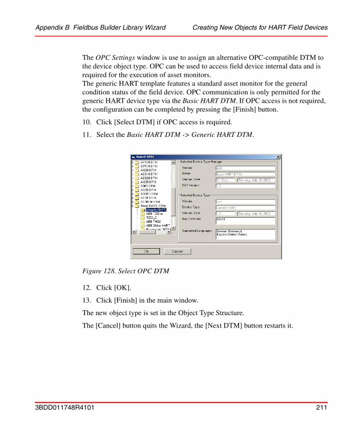
Appendix B Fieldbus Builder Library Wizard Creating New Objects for HART Field Devices
The OPC Settings window is use to assign an alternative OPC-compatible DTM to the device object type. OPC can be used to access field device internal data and is required for the execution of asset monitors. The generic HART template features a standard asset monitor for the general condition status of the field device. OPC communication is only permitted for the generic HART device type via the Basic HART DTM. If OPC access is not required, the configuration can be completed by pressing the [Finish] button.
10. Click [Select DTM] if OPC access is required.
11. Select the Basic HART DTM -> Generic HART DTM.
12. Click [OK].
13. Click [Finish] in the main window.
The new object type is set in the Object Type Structure.
The [Cancel] button quits the Wizard, the [Next DTM] button restarts it.
Figure 128. Select OPC DTM
3BDD011748R4101 211
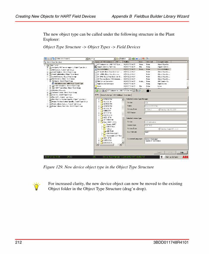
Creating New Objects for HART Field Devices Appendix B Fieldbus Builder Library Wizard
The new object type can be called under the following structure in the Plant Explorer:
Object Type Structure -> Object Types -> Field Devices
Figure 129. New device object type in the Object Type Structure
For increased clarity, the new device object can now be moved to the existing Object folder in the Object Type Structure (drag’n drop).
212 3BDD011748R4101
Appendix B Fieldbus Builder Library Wizard Creating New Objects for HART Field Devices
Change Object icon (optional):
1. Select the Object Icon aspect in the new object.
2. Select Set Icons in the aspect window
3. The browse window appears, where you can select a folder with the Icon library. When Process Portal A is installed, you can find an icon folder with predefined icons under:<Install drive>:\Program Files\ABB Industrial IT\Operate IT\Process Portal A\Icons
4. Select the new icon.
5. Confirm your selection with [Apply].
3BDD011748R4101 213

Creating New Objects for HART Field Devices Appendix B Fieldbus Builder Library Wizard
214 3BDD011748R4101
INDEX
AAdd Network for Multiplexer 159AI895 Module 50Aspect Control Connection 121Aspect Control Properties 48Aspect Device Definition 77Aspect Device Management 66, 84Aspect FBB PH Settings 35Aspect FBB-OPC Data Source Definition 44Aspect Fieldbus Management 84Aspect Install DTM 33Aspect Product Documentation 130Asset Monitoring 134Asset Optimization 134Asset Reporter 135Asset Viewer 135
CChange Object Icon 213Channel Objects 87CI854 Module 51CMMS Connectivity 136Communication Disabled 53Communication Enabled 53Components 21Configure OPC Server 69Context Menu 88Control Connection 103, 121
DDelete Objects 64Device Definition 74, 78, 103, 105Device Functions 65Device Functions Menu 55Device Integration Center 127
Device Integration Library 142Device Library Wizard 141Device Management 65, 74, 97Device Objects 87DIC 127DIP Fieldbus Builder PH Extension Definition 83DMS 138DMS Asset Monitor 138DMS Connectivity 138Download and Upload DTM Data Set 62DTM Project Root Path 39
EExport and Import DTM Data Set 62
FFault Report Submitter 137FBB PH Settings 74, 103FBB-OPC Configuration 75, 103FBB-OPC Data Source Definition 103FDT 1.2 User Roles 73FDT/DTM 71Fieldbus Builder PROFIBUS/HART 71Fieldbus Builder Status 94Fieldbus Management 74, 103Fieldbus Management Node 87 to 88Fieldbus Tree Window 86
GGeneric HART Actuator 206Generic HART Transmitter 206
HHART Actuators 128HART Device Integration Library 128
3BDD011748R4101 215
Index
HART DTM Setup Tool 33HART Multiplexer 147HART Multiplexer Connect 146HART Multiplexer Subnet 171HART Mux DTM 146HART Protocol 17HART Server 151HART Subnet DTM 146HART Transmitter 128
IInstrumentation 139
LList of HART Devices 182List of Multiplexer 174
MMaximo Equipment ID 137Message Window 95Module Definition 74Module Management 74Multiplexer 146Multiplexer Assignment 177
NNamespace 39New Object 41
OObject Icon 213Object Identification 195Object Information Window 94OPC Control Center 38
PParameter Mapping 138Parent Channel 197Prerequisites 142
PROFIBUS Management 74Property Management 75, 138
RRoot Node 41
SSave all Objects 199Scan Multiplexer Channels 162Scan Multiplexer Network 161Service Structure 40, 45Set Device Address 185Slot Number 50Source Object 195Status Bar 96System Requirements 141
TTemplate 208Toolrouting 48
UUNC Path 35User Roles 73, 150
VVerify DTM Data Set 61View Active Work Order 137View Equipment Status 137View Preventive Maintenance Schedule 137View Spare Parts 137View Work Order History 137
ZZip Archives 142
216 3BDD011748R4101

BackCover.fm Page 19 Wednesday, October 20, 2004 10:27 AM

3BDD011748R4101 Printed in Sweden May 2005Copyright © 2003-2005 by ABB. All Rights Reserved.® Registered Trademark of ABB™ Trademark of ABB
Automation Technology ProductsMannheim, Germanywww.abb.de/processautomationemail: [email protected]
Automation Technology ProductsWickliffe, Ohio, USAwww.abb.com/processautomationemail: [email protected]
Automation Technology Products Västerås, Swedenwww.abb.com/processautomationemail: [email protected]
http://www.abb.com/control