800xa for advant master graphic library - aotewell master/3bse03043… · 800xa - system 800xa for...
TRANSCRIPT
IndustrialIT800xA - System
800xA for Advant MasterSystem Version 4.0
Graphic Library


Graphic Library
IndustrialIT800xA - System
800xA for Advant MasterSystem Version 4.0
NOTICEThe information in this document is subject to change without notice and should not beconstrued as a commitment by ABB. ABB assumes no responsibility for any errors thatmay appear in this document.
In no event shall ABB be liable for direct, indirect, special, incidental or consequentialdamages of any nature or kind arising from the use of this document, nor shall ABB beliable for incidental or consequential damages arising from use of any software or hard-ware described in this document.
This document and parts thereof must not be reproduced or copied without written per-mission from ABB, and the contents thereof must not be imparted to a third party nor usedfor any unauthorized purpose.
The software or hardware described in this document is furnished under a license andmay be used, copied, or disclosed only in accordance with the terms of such license.
This product meets the requirements specified in EMC Directive 89/336/EEC and in LowVoltage Directive 72/23/EEC.
Copyright © 2003 - 2004 by ABB. All rights reserved. Release: October 2004Document number: 3BSE030430R4001
TRADEMARKSRegistrations and trademarks used in this document include:
Industrial IT Trademark of ABB.
Microsoft Registered trademark of Microsoft Corporation.
Windows Registered trademark of Microsoft Corporation.
Windows 2000 and Windows XP Registered trademarks of Microsoft Corporation.
ActiveX and Visual Basic Registered trademarks of Microsoft Corporation.
PostScript Registered trademark of Adobe Systems Inc.
Acrobat Reader Registered trademark of Adobe Systems Inc.
Ghost Registered trademark of Symantec Corporation.
Aspect Studio Trademark of ABB Ltd., Switzerland.
Aspect Express Trademark of ABB Ltd., Switzerland.
Process Portal Trademark of ABB Ltd., Switzerland.
TABLE OF CONTENTS
About This BookGeneral ..............................................................................................................................9
Intended User...................................................................................................................10
Use of Warning, Caution, Information, and Tip Icons ....................................................11
Document Conventions ...................................................................................................12
Terminology.....................................................................................................................13
Related Documentation ...................................................................................................15
Section 1 - Faceplates and Graphic ElementsAI, Analog Input..............................................................................................................18
Faceplate .............................................................................................................18
Object Display......................................................................................................26
Graphic Element...................................................................................................32
AO, Analog Output..........................................................................................................36
Faceplate .............................................................................................................36
Object Display......................................................................................................43
Graphic Element...................................................................................................47
DI, Digital input...............................................................................................................50
Faceplate .............................................................................................................50
Object Display......................................................................................................55
Graphic Elements .................................................................................................59
DAT, Data Base Parameters.............................................................................................60
Faceplate .............................................................................................................60
Graphic Element...................................................................................................69
3BSE030430R4001 5
Table of Contents
DO, Digital output........................................................................................................... 76
Faceplate ............................................................................................................ 76
Object Display ..................................................................................................... 81
Graphic Element .................................................................................................. 84
DRICONE, Engineered drive.......................................................................................... 87
Faceplate ............................................................................................................ 87
Displays ............................................................................................................ 98
Graphic Element ................................................................................................ 158
DRICONS, Standard drive ............................................................................................ 162
Faceplate .......................................................................................................... 162
Displays .......................................................................................................... 174
Graphic Element ................................................................................................ 198
GENBIN, Binary Object ............................................................................................... 203
Faceplate .......................................................................................................... 203
Object Display ................................................................................................... 211
Graphic Element ................................................................................................ 220
GENCON, PI Controller ............................................................................................... 225
Faceplate .......................................................................................................... 225
Object Display ................................................................................................... 235
Graphic Element ................................................................................................ 244
GENUSD, User Defined Object.................................................................................... 257
Faceplate .......................................................................................................... 257
Object Display ................................................................................................... 266
Graphic Element ................................................................................................ 278
GROUP ALARM, Group Alarm................................................................................... 289
Faceplate .......................................................................................................... 289
Object Display ................................................................................................... 295
Graphic Element ................................................................................................ 300
GROUP, Group Control ................................................................................................ 302
Faceplate .......................................................................................................... 302
Object Display ................................................................................................... 308
Graphic Element ................................................................................................ 315
6 3BSE030430R4001
Table of Contents
AC 400 Local Devices ...................................................................................................321
Display ...........................................................................................................321
MANSTN, Manual Station............................................................................................326
Faceplate ...........................................................................................................326
Object Display....................................................................................................337
Graphic Element.................................................................................................344
MOTCON, Motor Control.............................................................................................351
Faceplate ...........................................................................................................352
Object Display....................................................................................................360
Graphic Element.................................................................................................368
MOTCONI, Motor Control ...........................................................................................377
Faceplate ...........................................................................................................377
Displays ...........................................................................................................386
Graphic Element.................................................................................................412
PIDCONA, Adaptive PID Ctrl ......................................................................................423
Faceplate ...........................................................................................................423
Object Display....................................................................................................440
Graphic Element.................................................................................................458
PIDCON, PID Controller ..............................................................................................469
Faceplate ...........................................................................................................469
Object Display....................................................................................................483
Graphic Element.................................................................................................493
RATSTN, Ratio Station .................................................................................................505
Faceplate ...........................................................................................................505
Object Display....................................................................................................516
Graphic Element.................................................................................................523
SEQ, Sequence ..............................................................................................................531
Faceplate ...........................................................................................................532
Object Display....................................................................................................540
Graphic Element.................................................................................................549
3BSE030430R4001 73BSE030430R4001 7
Table of Contents
TEXT, Text data ............................................................................................................ 554
Faceplate .......................................................................................................... 554
ObjectDisplay .................................................................................................... 558
Graphic Element ................................................................................................ 559
VALVECON, Valve Control ......................................................................................... 562
Faceplate .......................................................................................................... 563
Object Display ................................................................................................... 569
Graphic Element ................................................................................................ 576
8 3BSE030430R4001
About This Book
GeneralThis book describes 800xA for Advant Master, which enables data retrieval from the Advant Controller 400 Series to the IndustrialIT 800xA Core System. 800xA for Advant Master contains built in graphic elements and faceplates for the below listed ABB standard object types:
– Analog Input AI
– Analog Output AO
– Data Base Parameters DAT(x)
– Digital Input DI
– Digital Output DO
– Engineered drive DRICONE
– Standard drive DRICONS
– Binary Object GENBIN
– PI Controller GENCON
– User Defined Object GENUSD
– Group Alarm GROUP
– Group Control GROUP
– Manual Station MANSTN
– Motor Control MOTCON
– Motor Control MOTCONI
– Adaptive PID Ctrl PIDCONA
3BSE030430R4001 9
Intended User About This Book
– PID Controller PIDCON
– Ratio Station RATSTN
– Sequence SEQ
– Text data TEXT
– Valve Control VALVECON
• The Control Connection Aspects (CCA) for each object type.
• Object Display.
• The graphic elements aspects of each type.
• A faceplate aspect for each type.
The Object types also include additional aspects such as an Icon aspect, an Alarm List aspect (for the instantiated object), and Trend aspect. This book is focused on describing the graphic elements and faceplates.
Intended UserThis instruction is intended for application engineers that build process graphics and make modifications to standard faceplates and graphic elements.
The reader should have experience with process control systems and Microsoft® Windows® operating systems. In general, Microsoft Windows functions are not described in this instruction.
The faceplate images in this manual are not updated to the latest versions. For example, the pin button in a faceplate is not shown.
10 3BSE030430R4001
About This Book Use of Warning, Caution, Information, and Tip Icons
Use of Warning, Caution, Information, and Tip IconsThis publication includes Warning, Caution, and Information where appropriate to point out safety related or other important information. It also includes Tip to point out useful hints to the reader. The corresponding symbols should be interpreted as follows:
Although Warning hazards are related to personal injury, and Caution hazards are associated with equipment or property damage, it should be understood that operation of damaged equipment could, under certain operational conditions, result in degraded process performance leading to personal injury or death. Therefore, comply fully with all Warning and Caution notices.
Electrical warning icon indicates the presence of a hazard which could result in electrical shock.
Warning icon indicates the presence of a hazard which could result in personal injury.
Caution icon indicates important information or warning related to the concept discussed in the text. It might indicate the presence of a hazard which could result in corruption of software or damage to equipment/property.
Information icon alerts the reader to pertinent facts and conditions.
Tip icon indicates advice on, for example, how to design your project or how to use a certain function
3BSE030430R4001 11
Document Conventions About This Book
Document ConventionsThe following conventions are used for the presentation of material:
• The words in names of screen elements (for example, the title in the title bar of a window, the label for a field of a dialog box) are initially capitalized.
• Capital letters are used for the name of a keyboard key if it is labeled on the keyboard. For example, press the ENTER key.
• Lowercase letters are used for the name of a keyboard key that is not labeled on the keyboard. For example, the space bar, comma key, and so on.
• Press CTRL+C indicates that you must hold down the CTRL key while pressing the C key (to copy a selected object in this case).
• Press ESC E C indicates that you press and release each key in sequence (to copy a selected object in this case).
• The names of push and toggle buttons are boldfaced. For example, click OK.
• The names of menus and menu items are boldfaced. For example, the File menu.
– The following convention is used for menu operations: MenuName > MenuItem > CascadedMenuItem. For example: select File > New > Type.
– The Start menu name always refers to the Start menu on the Windows Task Bar.
• System prompts/messages are shown in the Courier font, and user responses/input are in the boldfaced Courier font. For example, if you enter a value out of range, the following message is displayed:
Entered value is not valid. The value must be 0 to 30.
You may be told to enter the string TIC132 in a field. The string is shown as follows in the procedure:
TIC132
Variables are shown using lowercase letters.
sequence name
12 3BSE030430R4001
About This Book Terminology
TerminologyThe following is a list of terms associated with 800xA for Advant Master for AC 400 Series, that you should be familiar with. The list contains terms and abbreviations that are unique to ABB or have a usage or definition that is different from standard industry usage.
Term Description
Control connection aspect (CCA)
Contains the name, data type, access rights (read/write) and subscription update rate of each attribute and the name of the corresponding OPC item (object of the controller). CCA also contains a user interface to inspect the object type attribute information. It can also be used to subscribe for the current value of each attribute.
Faceplate Faceplates are used to monitor and control process data. A faceplate has a configuration view where you insert faceplate elements, buttons, status indicators and aspect links. The faceplate can have up to three run-time views: reduced, normal and extended, depending on how much information the user wants.
Faceplate element Faceplate elements are used both for presentation and modification of object properties. Faceplate elements are object aware.
Graphic display Graphic displays are aspects directly selected and viewed by the process operator.
Graphic element A graphic aspect that has a reference to an Aspect Object. Normally a part of a graphic display. A graphical object typically built up from several subelements and/or primitive elements. Some graphic elements are provided by ABB, while others may be built by the user.
3BSE030430R4001 13
Terminology About This Book
Graphic element browser
A tool used to select object aware (graphic) elements in Graphics Builder.
Graphic expression Graphic expression is used to specify a data subscription and a relationship between process data and data to be displayed.
Graphic libraries Libraries of primitive elements, and standard graphic elements, for example faceplate element, object display and graphic element.
Object display A graphic aspect that has a reference to an Aspect Object.
Term Description
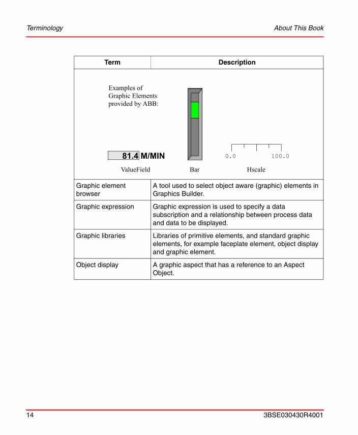
Examples of Graphic Elements provided by ABB:
81.4 M/MINValueField Bar Hscale
100.00.0
14 3BSE030430R4001
About This Book Related Documentation
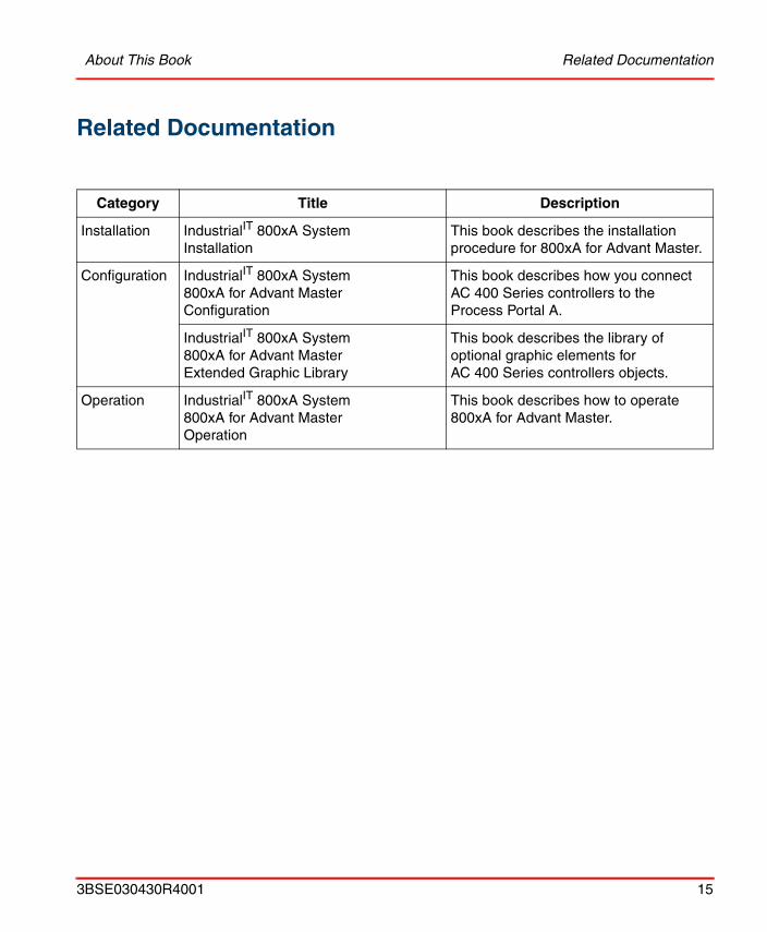
Related Documentation
Category Title Description
Installation IndustrialIT 800xA System Installation
This book describes the installation procedure for 800xA for Advant Master.
Configuration IndustrialIT 800xA System 800xA for Advant MasterConfiguration
This book describes how you connect AC 400 Series controllers to the Process Portal A.
IndustrialIT 800xA System 800xA for Advant MasterExtended Graphic Library
This book describes the library of optional graphic elements for AC 400 Series controllers objects.
Operation IndustrialIT 800xA System 800xA for Advant MasterOperation
This book describes how to operate 800xA for Advant Master.
3BSE030430R4001 15
Related Documentation About This Book
16 3BSE030430R4001
Section 1 Faceplates and Graphic Elements
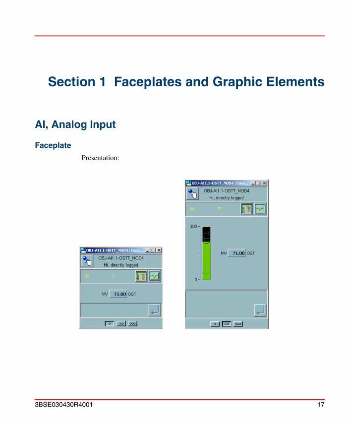
AI, Analog Input
Faceplate
Presentation:
3BSE030430R4001 17
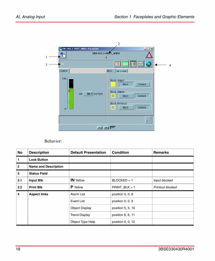
AI, Analog Input Section 1 Faceplates and Graphic Elements
Behavior:
No Description Default Presentation Condition Remarks
1 Lock Button
2 Name and Description
3 Status Field
3.1 Input Blk IN Yellow BLOCKED = 1 Input blocked
3.2 Print Blk P Yellow PRINT_BLK = 1 Printout blocked
4 Aspect links Alarm List position 0, 0, 8
Event List position 0, 0, 9
Object Display position 5, 5, 10
Trend Display position 6, 6, 11
Object Type Help position 0, 0, 12
1
3 4
2
18 3BSE030430R4001
Section 1 Faceplates and Graphic Elements AI, Analog Input
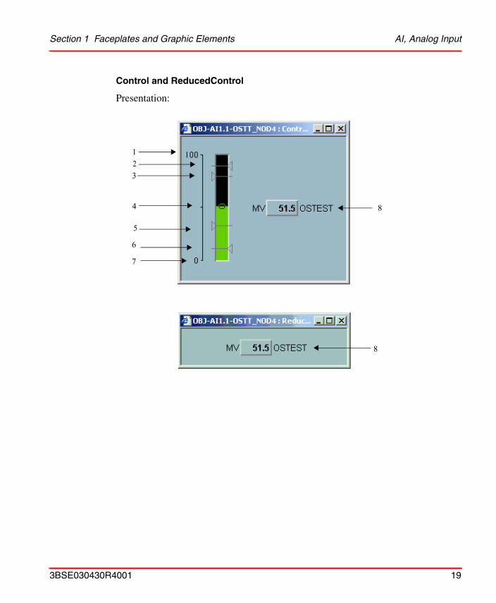
Control and ReducedControl
Presentation:
12
4
3
5
6
7
8
8
3BSE030430R4001 19
AI, Analog Input Section 1 Faceplates and Graphic Elements
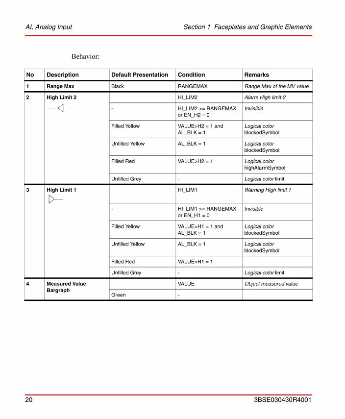
Behavior:
No Description Default Presentation Condition Remarks
1 Range Max Black RANGEMAX Range Max of the MV value
2 High Limit 2 HI_LIM2 Alarm High limit 2
- HI_LIM2 >= RANGEMAX or EN_H2 = 0
Invisible
Filled Yellow VALUE>H2 = 1 and AL_BLK = 1
Logical colorblockedSymbol
Unfilled Yellow AL_BLK = 1 Logical colorblockedSymbol
Filled Red VALUE>H2 = 1 Logical colorhighAlarmSymbol
Unfilled Grey - Logical color limit
3 High Limit 1 HI_LIM1 Warning High limit 1
- HI_LIM1 >= RANGEMAX or EN_H1 = 0
Invisible
Filled Yellow VALUE>H1 = 1 and AL_BLK = 1
Logical colorblockedSymbol
Unfilled Yellow AL_BLK = 1 Logical colorblockedSymbol
Filled Red VALUE>H1 = 1
Unfilled Grey - Logical color limit
4 Measured Value Bargraph
VALUE Object measured value
Green -
20 3BSE030430R4001
Section 1 Faceplates and Graphic Elements AI, Analog Input
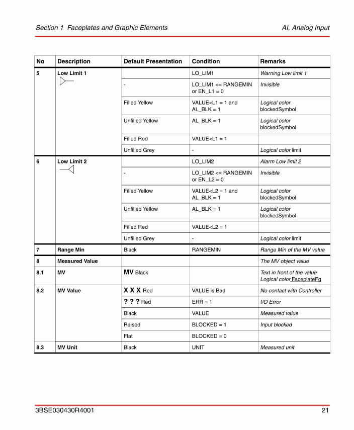
5 Low Limit 1 LO_LIM1 Warning Low limit 1
- LO_LIM1 <= RANGEMIN or EN_L1 = 0
Invisible
Filled Yellow VALUE<L1 = 1 and AL_BLK = 1
Logical colorblockedSymbol
Unfilled Yellow AL_BLK = 1 Logical colorblockedSymbol
Filled Red VALUE<L1 = 1
Unfilled Grey - Logical color limit
6 Low Limit 2 LO_LIM2 Alarm Low limit 2
- LO_LIM2 <= RANGEMIN or EN_L2 = 0
Invisible
Filled Yellow VALUE<L2 = 1 and AL_BLK = 1
Logical colorblockedSymbol
Unfilled Yellow AL_BLK = 1 Logical colorblockedSymbol
Filled Red VALUE<L2 = 1
Unfilled Grey - Logical color limit
7 Range Min Black RANGEMIN Range Min of the MV value
8 Measured Value The MV object value
8.1 MV MV Black Text in front of the valueLogical color FaceplateFg
8.2 MV Value X X X Red VALUE is Bad No contact with Controller
? ? ? Red ERR = 1 I/O Error
Black VALUE Measured value
Raised BLOCKED = 1 Input blocked
Flat BLOCKED = 0
8.3 MV Unit Black UNIT Measured unit
No Description Default Presentation Condition Remarks
3BSE030430R4001 21
AI, Analog Input Section 1 Faceplates and Graphic Elements
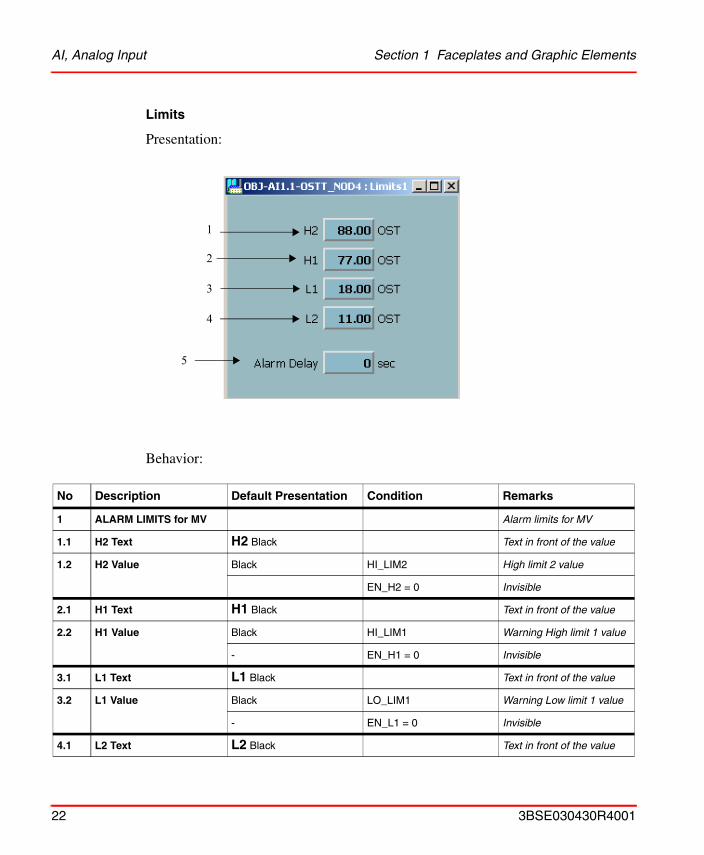
Limits
Presentation:
Behavior:
No Description Default Presentation Condition Remarks
1 ALARM LIMITS for MV Alarm limits for MV
1.1 H2 Text H2 Black Text in front of the value
1.2 H2 Value Black HI_LIM2 High limit 2 value
EN_H2 = 0 Invisible
2.1 H1 Text H1 Black Text in front of the value
2.2 H1 Value Black HI_LIM1 Warning High limit 1 value
- EN_H1 = 0 Invisible
3.1 L1 Text L1 Black Text in front of the value
3.2 L1 Value Black LO_LIM1 Warning Low limit 1 value
- EN_L1 = 0 Invisible
4.1 L2 Text L2 Black Text in front of the value
1
2
3
4
5
22 3BSE030430R4001
Section 1 Faceplates and Graphic Elements AI, Analog Input
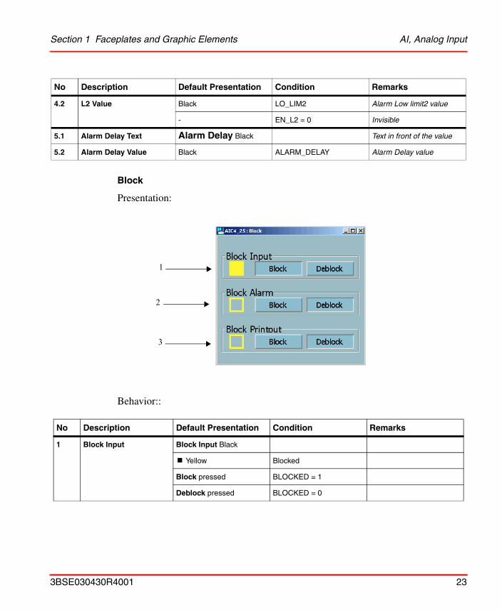
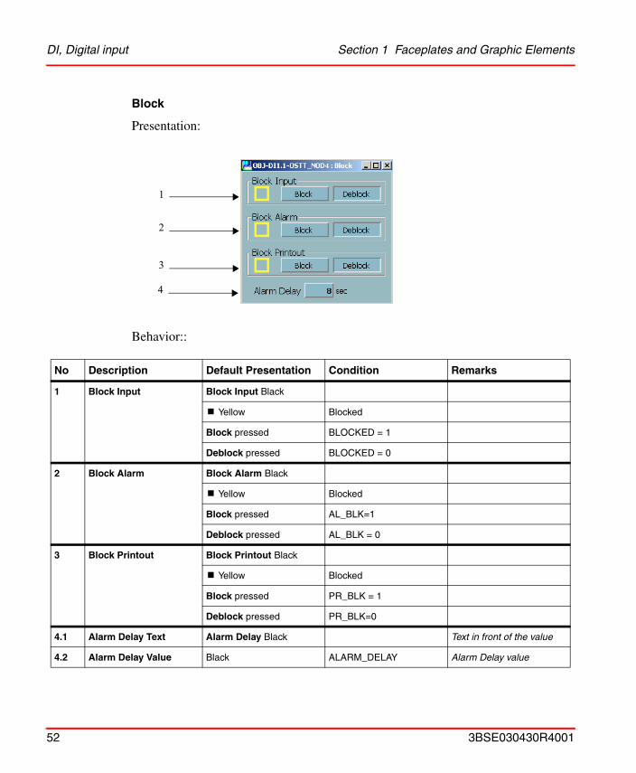
Block
Presentation:
Behavior::
4.2 L2 Value Black LO_LIM2 Alarm Low limit2 value
- EN_L2 = 0 Invisible
5.1 Alarm Delay Text Alarm Delay Black Text in front of the value
5.2 Alarm Delay Value Black ALARM_DELAY Alarm Delay value
No Description Default Presentation Condition Remarks
1 Block Input Block Input Black
! Yellow Blocked
Block pressed BLOCKED = 1
Deblock pressed BLOCKED = 0
No Description Default Presentation Condition Remarks
1
2
3
3BSE030430R4001 23
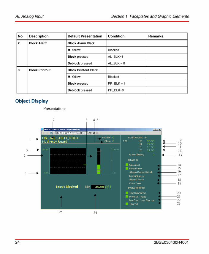
AI, Analog Input Section 1 Faceplates and Graphic Elements
Object Display
Presentation:
2 Block Alarm Block Alarm Black
! Yellow Blocked
Block pressed AL_BLK=1
Deblock pressed AL_BLK = 0
3 Block Printout Block Printout Black
! Yellow Blocked
Block pressed PR_BLK = 1
Deblock pressed PR_BLK=0
No Description Default Presentation Condition Remarks
19
2021
9101112
1718
141516
22
24
6
75
1
2
25
4 38
23
13
24 3BSE030430R4001
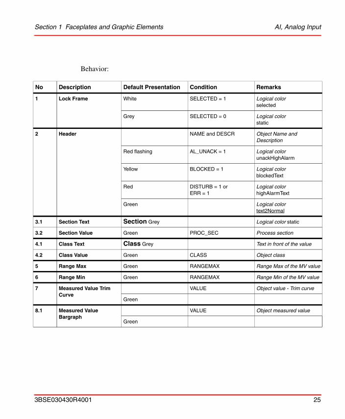
Section 1 Faceplates and Graphic Elements AI, Analog Input
Behavior:
No Description Default Presentation Condition Remarks
1 Lock Frame White SELECTED = 1 Logical colorselected
Grey SELECTED = 0 Logical colorstatic
2 Header NAME and DESCR Object Name and Description
Red flashing AL_UNACK = 1 Logical colorunackHighAlarm
Yellow BLOCKED = 1 Logical colorblockedText
Red DISTURB = 1 or ERR = 1
Logical colorhighAlarmText
Green Logical colortext2Normal
3.1 Section Text Section Grey Logical color static
3.2 Section Value Green PROC_SEC Process section
4.1 Class Text Class Grey Text in front of the value
4.2 Class Value Green CLASS Object class
5 Range Max Green RANGEMAX Range Max of the MV value
6 Range Min Green RANGEMAX Range Min of the MV value
7 Measured Value Trim Curve
VALUE Object value - Trim curve
Green
8.1 Measured Value Bargraph
VALUE Object measured value
Green
3BSE030430R4001 25
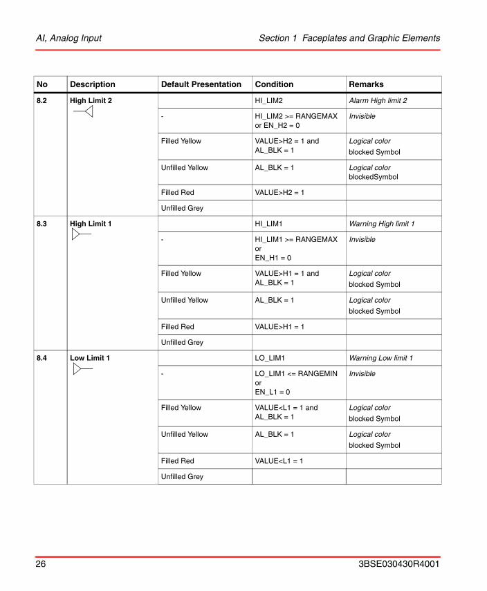
AI, Analog Input Section 1 Faceplates and Graphic Elements
8.2 High Limit 2 HI_LIM2 Alarm High limit 2
- HI_LIM2 >= RANGEMAX or EN_H2 = 0
Invisible
Filled Yellow VALUE>H2 = 1 and AL_BLK = 1
Logical color
blocked Symbol
Unfilled Yellow AL_BLK = 1 Logical colorblockedSymbol
Filled Red VALUE>H2 = 1
Unfilled Grey
8.3 High Limit 1 HI_LIM1 Warning High limit 1
- HI_LIM1 >= RANGEMAX orEN_H1 = 0
Invisible
Filled Yellow VALUE>H1 = 1 and AL_BLK = 1
Logical color
blocked Symbol
Unfilled Yellow AL_BLK = 1 Logical color
blocked Symbol
Filled Red VALUE>H1 = 1
Unfilled Grey
8.4 Low Limit 1 LO_LIM1 Warning Low limit 1
- LO_LIM1 <= RANGEMIN orEN_L1 = 0
Invisible
Filled Yellow VALUE<L1 = 1 and AL_BLK = 1
Logical color
blocked Symbol
Unfilled Yellow AL_BLK = 1 Logical color
blocked Symbol
Filled Red VALUE<L1 = 1
Unfilled Grey
No Description Default Presentation Condition Remarks
26 3BSE030430R4001
Section 1 Faceplates and Graphic Elements AI, Analog Input
8.5 Low Limit 2 LO_LIM2 Alarm Low limit 2
- LO_LIM2 <= RANGEMIN orEN_L2 = 0
Invisible
Filled Yellow VALUE<L2 = 1 and AL_BLK = 1
Logical color
blocked Symbol
Unfilled Yellow AL_BLK = 1 Logical color
blocked Symbol
Filled Red VALUE<L2 = 1
Unfilled Grey
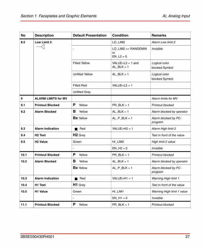
9 ALARM LIMITS for MV Alarm limits for MV
9.1 Printout Blocked P Yellow PR_BLK = 1 Printout blocked
9.2 Alarm Blocked B Yellow AL_BLK = 1 Alarm blocked by operator
Bx Yellow AL_P_BLK = 1 Alarm blocked by PC-program
9.3 Alarm Indication Red VALUE>H2 = 1 Alarm High limit 2
9.4 H2 Text H2 Grey Text in front of the value
9.5 H2 Value Green HI_LIM2 High limit 2 value
- EN_H2 = 0 Invisible
10.1 Printout Blocked P Yellow PR_BLK = 1 Printout blocked
10.2 Alarm Blocked B Yellow AL_BLK = 1 Alarm blocked by operator
Bx Yellow AL_P_BLK = 1 Alarm blocked by PC-program
10.3 Alarm Indication Red VALUE>H1 = 1 Warning High limit 1
10.4 H1 Text H1 Grey Text in front of the value
10.5 H1 Value Green HI_LIM1 Warning High limit 1 value
- EN_H1 = 0 Invisible
11.1 Printout Blocked P Yellow PR_BLK = 1 Printout blocked
No Description Default Presentation Condition Remarks
3BSE030430R4001 27
AI, Analog Input Section 1 Faceplates and Graphic Elements
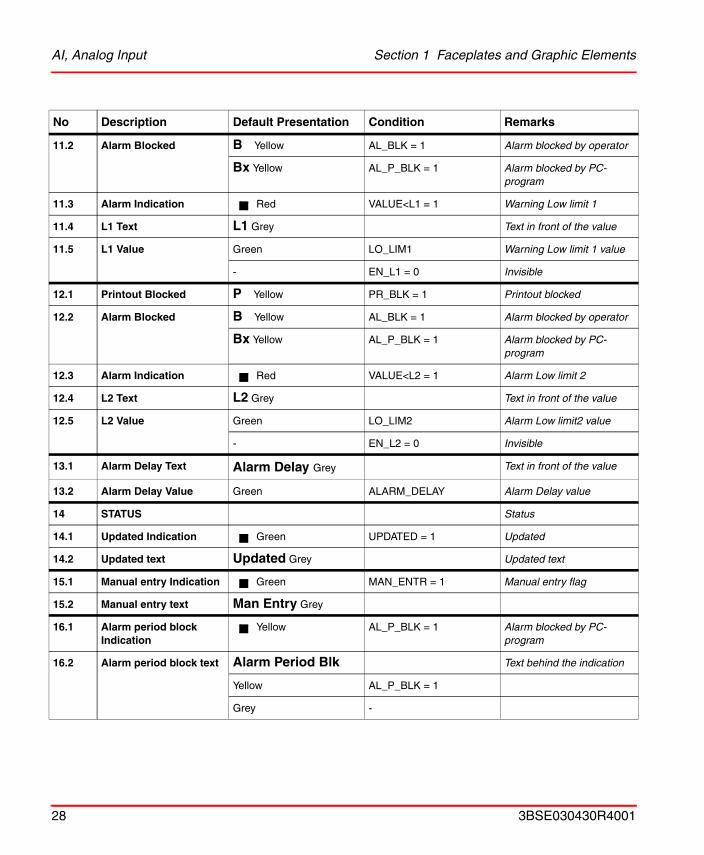
11.2 Alarm Blocked B Yellow AL_BLK = 1 Alarm blocked by operator
Bx Yellow AL_P_BLK = 1 Alarm blocked by PC-program
11.3 Alarm Indication Red VALUE<L1 = 1 Warning Low limit 1
11.4 L1 Text L1 Grey Text in front of the value
11.5 L1 Value Green LO_LIM1 Warning Low limit 1 value
- EN_L1 = 0 Invisible
12.1 Printout Blocked P Yellow PR_BLK = 1 Printout blocked
12.2 Alarm Blocked B Yellow AL_BLK = 1 Alarm blocked by operator
Bx Yellow AL_P_BLK = 1 Alarm blocked by PC-program
12.3 Alarm Indication Red VALUE<L2 = 1 Alarm Low limit 2
12.4 L2 Text L2 Grey Text in front of the value
12.5 L2 Value Green LO_LIM2 Alarm Low limit2 value
- EN_L2 = 0 Invisible
13.1 Alarm Delay Text Alarm Delay Grey Text in front of the value
13.2 Alarm Delay Value Green ALARM_DELAY Alarm Delay value
14 STATUS Status
14.1 Updated Indication Green UPDATED = 1 Updated
14.2 Updated text Updated Grey Updated text
15.1 Manual entry Indication Green MAN_ENTR = 1 Manual entry flag
15.2 Manual entry text Man Entry Grey
16.1 Alarm period block Indication
Yellow AL_P_BLK = 1 Alarm blocked by PC-program
16.2 Alarm period block text Alarm Period Blk Text behind the indication
Yellow AL_P_BLK = 1
Grey -
No Description Default Presentation Condition Remarks
28 3BSE030430R4001
Section 1 Faceplates and Graphic Elements AI, Analog Input
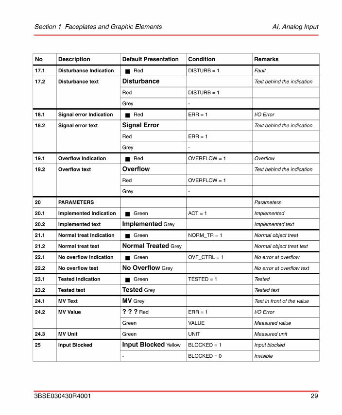
17.1 Disturbance Indication Red DISTURB = 1 Fault
17.2 Disturbance text Disturbance Text behind the indication
Red DISTURB = 1
Grey -
18.1 Signal error Indication Red ERR = 1 I/O Error
18.2 Signal error text Signal Error Text behind the indication
Red ERR = 1
Grey -
19.1 Overflow Indication Red OVERFLOW = 1 Overflow
19.2 Overflow text Overflow Text behind the indication
Red OVERFLOW = 1
Grey -
20 PARAMETERS Parameters
20.1 Implemented Indication Green ACT = 1 Implemented
20.2 Implemented text Implemented Grey Implemented text
21.1 Normal treat Indication Green NORM_TR = 1 Normal object treat
21.2 Normal treat text Normal Treated Grey Normal object treat text
22.1 No overflow Indication Green OVF_CTRL = 1 No error at overflow
22.2 No overflow text No Overflow Grey No error at overflow text
23.1 Tested Indication Green TESTED = 1 Tested
23.2 Tested text Tested Grey Tested text
24.1 MV Text MV Grey Text in front of the value
24.2 MV Value ? ? ? Red ERR = 1 I/O Error
Green VALUE Measured value
24.3 MV Unit Green UNIT Measured unit
25 Input Blocked Input Blocked Yellow BLOCKED = 1 Input blocked
- BLOCKED = 0 Invisible
No Description Default Presentation Condition Remarks
3BSE030430R4001 29
AI, Analog Input Section 1 Faceplates and Graphic Elements
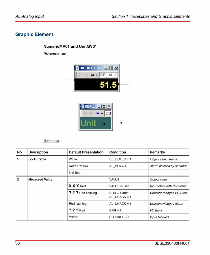
Graphic Element
NumericMV01 and UnitMV01
Presentation:
Behavior:
No Description Default Presentation Condition Remarks
1 Lock Frame White SELECTED = 1 Object select frame
Dotted Yellow AL_BLK = 1 Alarm blocked by operator
Invisible
2 Measured Value VALUE Object value
X X X Red VALUE is Bad No contact with Controller
? ? ? Red flashing ERR = 1 andAL_UNACK = 1
Unacknowledged I/O Error
Red flashing AL_UNACK = 1 Unacknowledged alarm
? ? ? Red ERR = 1 I/O Error
Yellow BLOCKED =1 Input blocked
12
3
30 3BSE030430R4001
Section 1 Faceplates and Graphic Elements AI, Analog Input
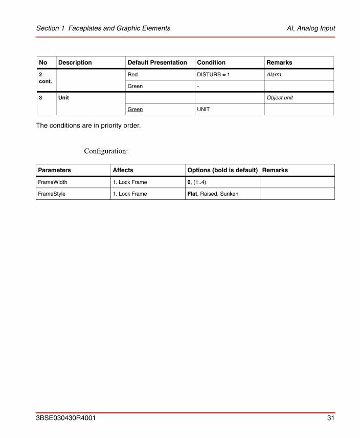
The conditions are in priority order.
Configuration:
2 cont.
Red DISTURB = 1 Alarm
Green -
3 Unit Object unit
Green UNIT
Parameters Affects Options (bold is default) Remarks
FrameWidth 1. Lock Frame 0, (1..4)
FrameStyle 1. Lock Frame Flat, Raised, Sunken
No Description Default Presentation Condition Remarks
3BSE030430R4001 31
AI, Analog Input Section 1 Faceplates and Graphic Elements
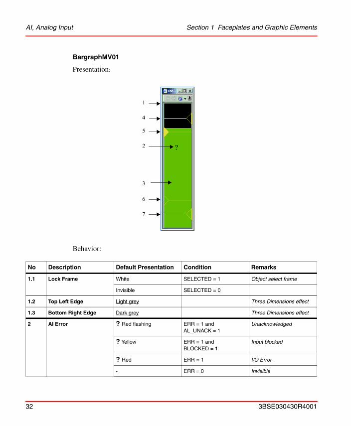
BargraphMV01
Presentation:
Behavior:
No Description Default Presentation Condition Remarks
1.1 Lock Frame White SELECTED = 1 Object select frame
Invisible SELECTED = 0
1.2 Top Left Edge Light grey Three Dimensions effect
1.3 Bottom Right Edge Dark grey Three Dimensions effect
2 AI Error ? Red flashing ERR = 1 and AL_UNACK = 1
Unacknowledged
? Yellow ERR = 1 and BLOCKED = 1
Input blocked
? Red ERR = 1 I/O Error
- ERR = 0 Invisible
1
2
3
4
6
7
?
5
32 3BSE030430R4001
Section 1 Faceplates and Graphic Elements AI, Analog Input
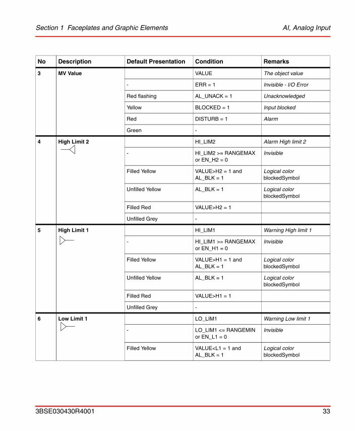
3 MV Value VALUE The object value
- ERR = 1 Invisible - I/O Error
Red flashing AL_UNACK = 1 Unacknowledged
Yellow BLOCKED = 1 Input blocked
Red DISTURB = 1 Alarm
Green -
4 High Limit 2 HI_LIM2 Alarm High limit 2
- HI_LIM2 >= RANGEMAX or EN_H2 = 0
Invisible
Filled Yellow VALUE>H2 = 1 and AL_BLK = 1
Logical colorblockedSymbol
Unfilled Yellow AL_BLK = 1 Logical colorblockedSymbol
Filled Red VALUE>H2 = 1
Unfilled Grey -
5 High Limit 1 HI_LIM1 Warning High limit 1
- HI_LIM1 >= RANGEMAX or EN_H1 = 0
Invisible
Filled Yellow VALUE>H1 = 1 and AL_BLK = 1
Logical colorblockedSymbol
Unfilled Yellow AL_BLK = 1 Logical colorblockedSymbol
Filled Red VALUE>H1 = 1
Unfilled Grey -
6 Low Limit 1 LO_LIM1 Warning Low limit 1
- LO_LIM1 <= RANGEMIN or EN_L1 = 0
Invisible
Filled Yellow VALUE<L1 = 1 and AL_BLK = 1
Logical colorblockedSymbol
No Description Default Presentation Condition Remarks
3BSE030430R4001 33
AI, Analog Input Section 1 Faceplates and Graphic Elements
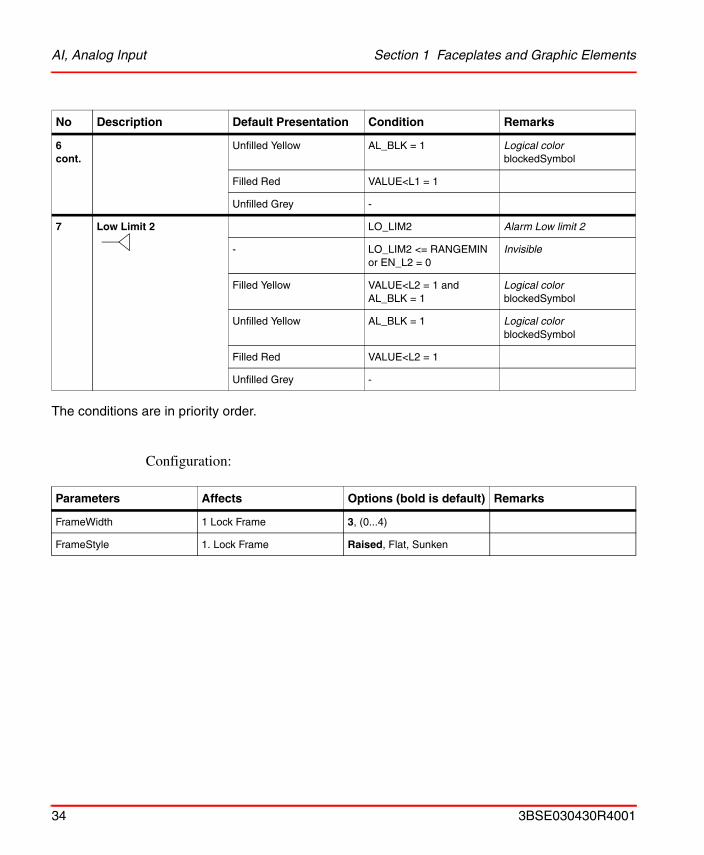
The conditions are in priority order.
Configuration:
6 cont.
Unfilled Yellow AL_BLK = 1 Logical colorblockedSymbol
Filled Red VALUE<L1 = 1
Unfilled Grey -
7 Low Limit 2 LO_LIM2 Alarm Low limit 2
- LO_LIM2 <= RANGEMIN or EN_L2 = 0
Invisible
Filled Yellow VALUE<L2 = 1 and AL_BLK = 1
Logical colorblockedSymbol
Unfilled Yellow AL_BLK = 1 Logical colorblockedSymbol
Filled Red VALUE<L2 = 1
Unfilled Grey -
Parameters Affects Options (bold is default) Remarks
FrameWidth 1 Lock Frame 3, (0...4)
FrameStyle 1. Lock Frame Raised, Flat, Sunken
No Description Default Presentation Condition Remarks
34 3BSE030430R4001
Section 1 Faceplates and Graphic Elements AO, Analog Output
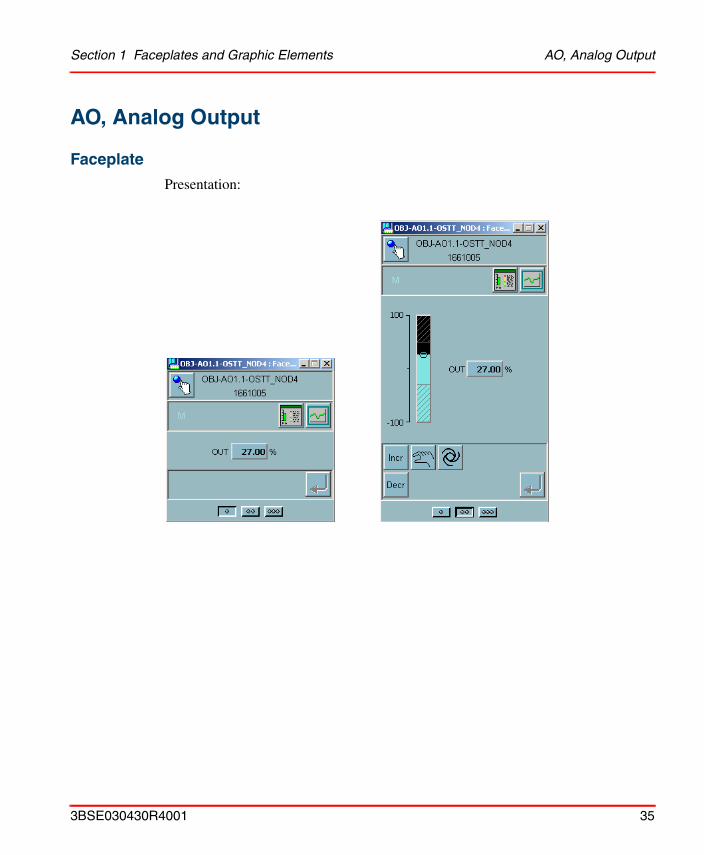
AO, Analog Output
Faceplate
Presentation:
3BSE030430R4001 35
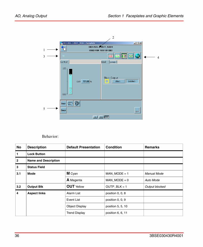
AO, Analog Output Section 1 Faceplates and Graphic Elements
Behavior:
No Description Default Presentation Condition Remarks
1 Lock Button
2 Name and Description
3 Status Field
3.1 Mode M Cyan MAN_MODE = 1 Manual Mode
A Magenta MAN_MODE = 0 Auto Mode
3.2 Output Blk OUT Yellow OUTP_BLK = 1 Output blocked
4 Aspect links Alarm List position 0, 0, 8
Event List position 0, 0, 9
Object Display position 5, 5, 10
Trend Display position 6, 6, 11
1
3
2
4
5
36 3BSE030430R4001
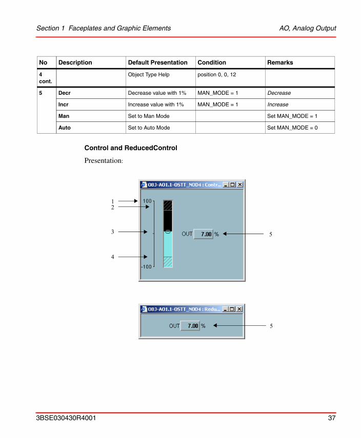
Section 1 Faceplates and Graphic Elements AO, Analog Output
Control and ReducedControl
Presentation:
4 cont.
Object Type Help position 0, 0, 12
5 Decr Decrease value with 1% MAN_MODE = 1 Decrease
Incr Increase value with 1% MAN_MODE = 1 Increase
Man Set to Man Mode Set MAN_MODE = 1
Auto Set to Auto Mode Set MAN_MODE = 0
No Description Default Presentation Condition Remarks
12
4
3 5
5
3BSE030430R4001 37
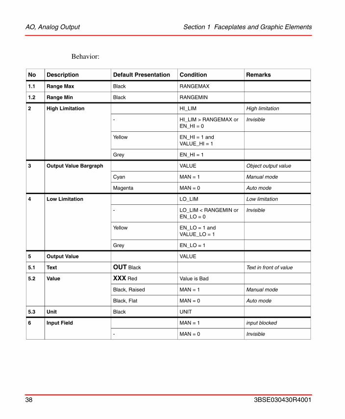
AO, Analog Output Section 1 Faceplates and Graphic Elements
Behavior:
No Description Default Presentation Condition Remarks
1.1 Range Max Black RANGEMAX
1.2 Range Min Black RANGEMIN
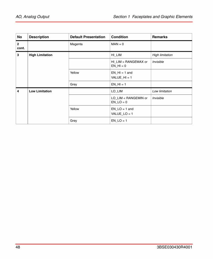
2 High Limitation HI_LIM High limitation
- HI_LIM > RANGEMAX or EN_HI = 0
Invisible
Yellow EN_HI = 1 andVALUE_HI = 1
Grey EN_HI = 1
3 Output Value Bargraph VALUE Object output value
Cyan MAN = 1 Manual mode
Magenta MAN = 0 Auto mode
4 Low Limitation LO_LIM Low limitation
- LO_LIM < RANGEMIN orEN_LO = 0
Invisible
Yellow EN_LO = 1 andVALUE_LO = 1
Grey EN_LO = 1
5 Output Value VALUE
5.1 Text OUT Black Text in front of value
5.2 Value XXX Red Value is Bad
Black, Raised MAN = 1 Manual mode
Black, Flat MAN = 0 Auto mode
5.3 Unit Black UNIT
6 Input Field MAN = 1 input blocked
- MAN = 0 Invisible
38 3BSE030430R4001

Section 1 Faceplates and Graphic Elements AO, Analog Output
Block
Presentation:
Behavior:
No Description Default Presentation Condition Remarks
1 Block Output Block Output Black
! Yellow Blocked
Block pressed BLOCKED = 1
Deblock pressed BLOCKED = 0
1
3BSE030430R4001 39
AO, Analog Output Section 1 Faceplates and Graphic Elements
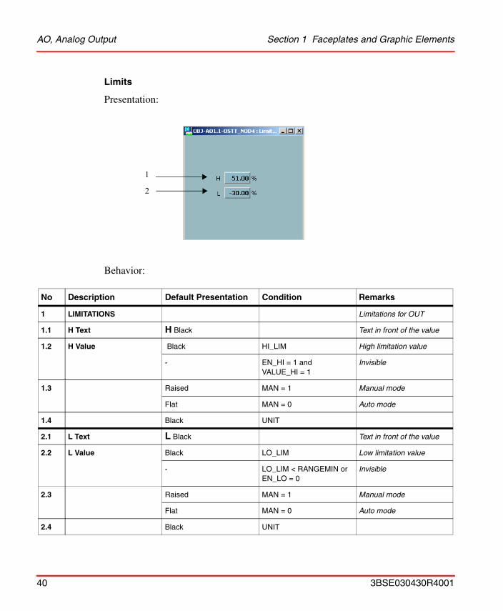
Limits
Presentation:
Behavior:
No Description Default Presentation Condition Remarks
1 LIMITATIONS Limitations for OUT
1.1 H Text H Black Text in front of the value
1.2 H Value Black HI_LIM High limitation value
- EN_HI = 1 andVALUE_HI = 1
Invisible
1.3 Raised MAN = 1 Manual mode
Flat MAN = 0 Auto mode
1.4 Black UNIT
2.1 L Text L Black Text in front of the value
2.2 L Value Black LO_LIM Low limitation value
- LO_LIM < RANGEMIN orEN_LO = 0
Invisible
2.3 Raised MAN = 1 Manual mode
Flat MAN = 0 Auto mode
2.4 Black UNIT
2
1
40 3BSE030430R4001
Section 1 Faceplates and Graphic Elements AO, Analog Output
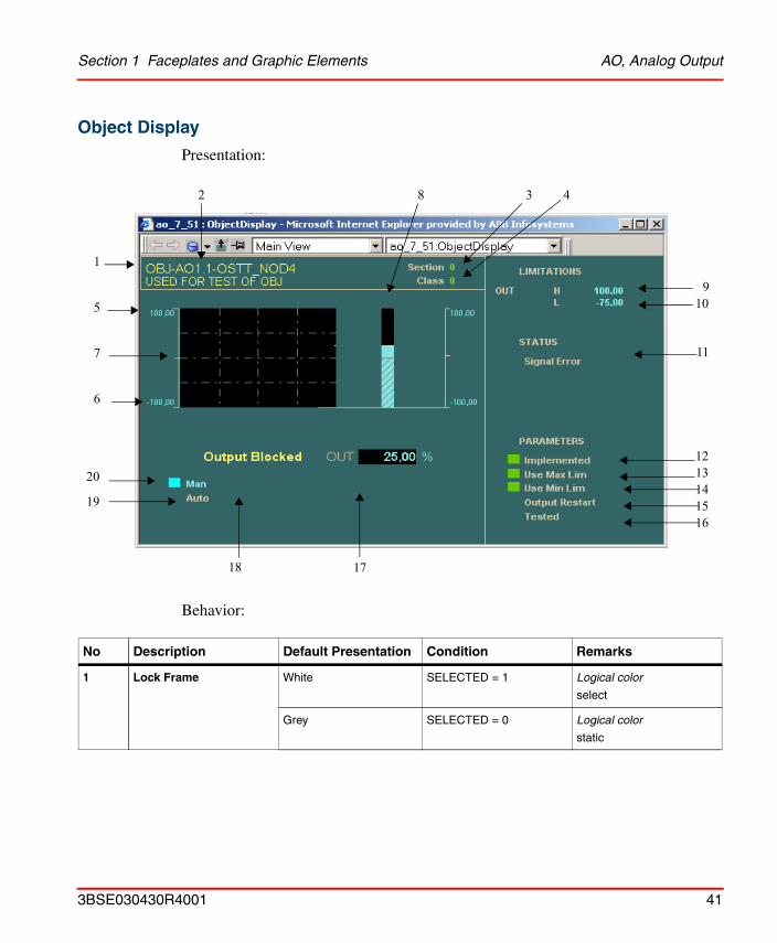
Object Display
Presentation:
Behavior:
No Description Default Presentation Condition Remarks
1 Lock Frame White SELECTED = 1 Logical color
select
Grey SELECTED = 0 Logical color
static
3 4
5
7
1
6
20
19
18 17
1615141312
11
8
10
2
9
3BSE030430R4001 41
AO, Analog Output Section 1 Faceplates and Graphic Elements
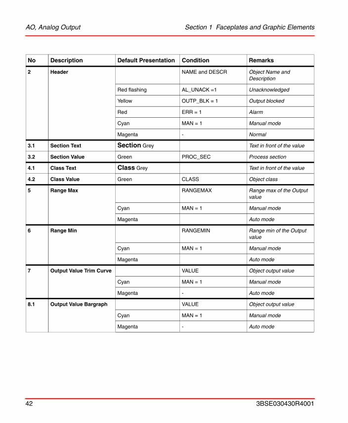
2 Header NAME and DESCR Object Name and Description
Red flashing AL_UNACK =1 Unacknowledged
Yellow OUTP_BLK = 1 Output blocked
Red ERR = 1 Alarm
Cyan MAN = 1 Manual mode
Magenta - Normal
3.1 Section Text Section Grey Text in front of the value
3.2 Section Value Green PROC_SEC Process section
4.1 Class Text Class Grey Text in front of the value
4.2 Class Value Green CLASS Object class
5 Range Max RANGEMAX Range max of the Output value
Cyan MAN = 1 Manual mode
Magenta Auto mode
6 Range Min RANGEMIN Range min of the Outputvalue
Cyan MAN = 1 Manual mode
Magenta Auto mode
7 Output Value Trim Curve VALUE Object output value
Cyan MAN = 1 Manual mode
Magenta - Auto mode
8.1 Output Value Bargraph VALUE Object output value
Cyan MAN = 1 Manual mode
Magenta - Auto mode
No Description Default Presentation Condition Remarks
42 3BSE030430R4001
Section 1 Faceplates and Graphic Elements AO, Analog Output
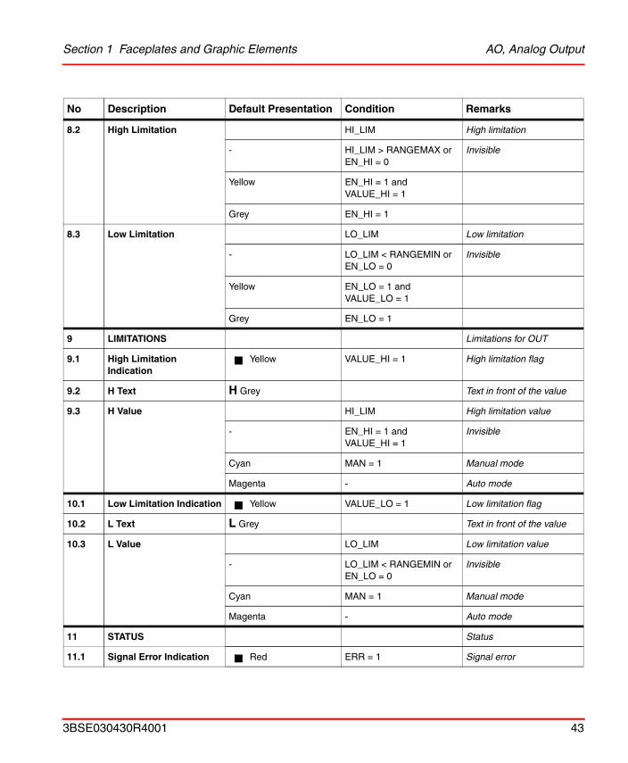
8.2 High Limitation HI_LIM High limitation
- HI_LIM > RANGEMAX or EN_HI = 0
Invisible
Yellow EN_HI = 1 andVALUE_HI = 1
Grey EN_HI = 1
8.3 Low Limitation LO_LIM Low limitation
- LO_LIM < RANGEMIN orEN_LO = 0
Invisible
Yellow EN_LO = 1 andVALUE_LO = 1
Grey EN_LO = 1
9 LIMITATIONS Limitations for OUT
9.1 High Limitation Indication
Yellow VALUE_HI = 1 High limitation flag
9.2 H Text H Grey Text in front of the value
9.3 H Value HI_LIM High limitation value
- EN_HI = 1 andVALUE_HI = 1
Invisible
Cyan MAN = 1 Manual mode
Magenta - Auto mode
10.1 Low Limitation Indication Yellow VALUE_LO = 1 Low limitation flag
10.2 L Text L Grey Text in front of the value
10.3 L Value LO_LIM Low limitation value
- LO_LIM < RANGEMIN orEN_LO = 0
Invisible
Cyan MAN = 1 Manual mode
Magenta - Auto mode
11 STATUS Status
11.1 Signal Error Indication Red ERR = 1 Signal error
No Description Default Presentation Condition Remarks
3BSE030430R4001 43
AO, Analog Output Section 1 Faceplates and Graphic Elements
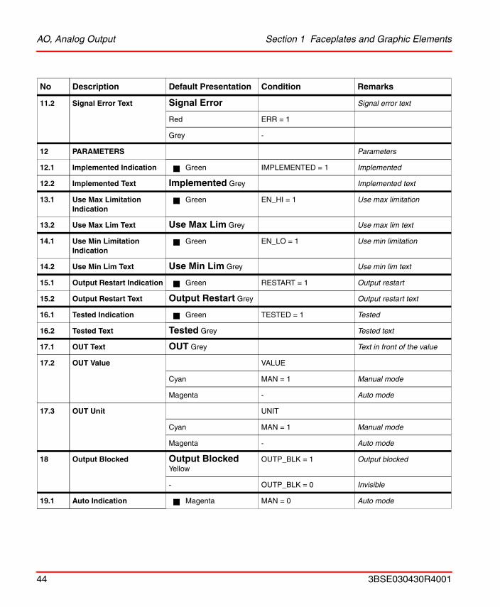
11.2 Signal Error Text Signal Error Signal error text
Red ERR = 1
Grey -
12 PARAMETERS Parameters
12.1 Implemented Indication Green IMPLEMENTED = 1 Implemented
12.2 Implemented Text Implemented Grey Implemented text
13.1 Use Max Limitation Indication
Green EN_HI = 1 Use max limitation
13.2 Use Max Lim Text Use Max Lim Grey Use max lim text
14.1 Use Min Limitation Indication
Green EN_LO = 1 Use min limitation
14.2 Use Min Lim Text Use Min Lim Grey Use min lim text
15.1 Output Restart Indication Green RESTART = 1 Output restart
15.2 Output Restart Text Output Restart Grey Output restart text
16.1 Tested Indication Green TESTED = 1 Tested
16.2 Tested Text Tested Grey Tested text
17.1 OUT Text OUT Grey Text in front of the value
17.2 OUT Value VALUE
Cyan MAN = 1 Manual mode
Magenta - Auto mode
17.3 OUT Unit UNIT
Cyan MAN = 1 Manual mode
Magenta - Auto mode
18 Output Blocked Output Blocked Yellow
OUTP_BLK = 1 Output blocked
- OUTP_BLK = 0 Invisible
19.1 Auto Indication Magenta MAN = 0 Auto mode
No Description Default Presentation Condition Remarks
44 3BSE030430R4001
Section 1 Faceplates and Graphic Elements AO, Analog Output
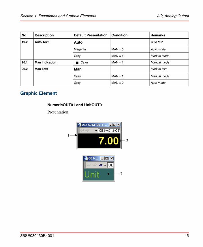
Graphic Element
NumericOUT01 and UnitOUT01
Presentation:
19.2 Auto Text Auto Auto text
Magenta MAN = 0 Auto mode
Grey MAN = 1 Manual mode
20.1 Man Indication Cyan MAN = 1 Manual mode
20.2 Man Text Man Manual text
Cyan MAN = 1 Manual mode
Grey MAN = 0 Auto mode
No Description Default Presentation Condition Remarks
21
3
3BSE030430R4001 45
AO, Analog Output Section 1 Faceplates and Graphic Elements
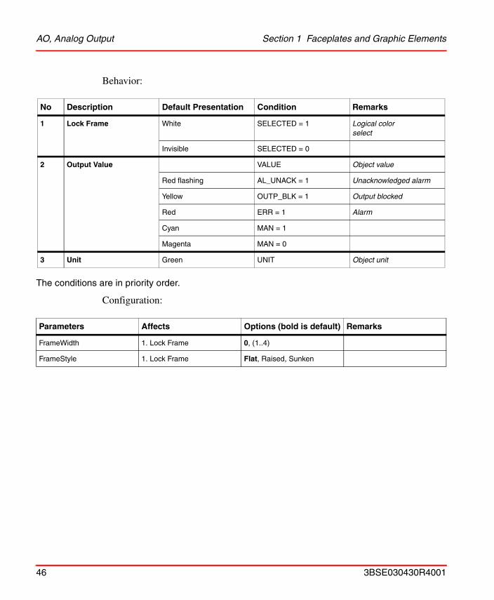
Behavior:
The conditions are in priority order.
Configuration:
No Description Default Presentation Condition Remarks
1 Lock Frame White SELECTED = 1 Logical colorselect
Invisible SELECTED = 0
2 Output Value VALUE Object value
Red flashing AL_UNACK = 1 Unacknowledged alarm
Yellow OUTP_BLK = 1 Output blocked
Red ERR = 1 Alarm
Cyan MAN = 1
Magenta MAN = 0
3 Unit Green UNIT Object unit
Parameters Affects Options (bold is default) Remarks
FrameWidth 1. Lock Frame 0, (1..4)
FrameStyle 1. Lock Frame Flat, Raised, Sunken
46 3BSE030430R4001
Section 1 Faceplates and Graphic Elements AO, Analog Output
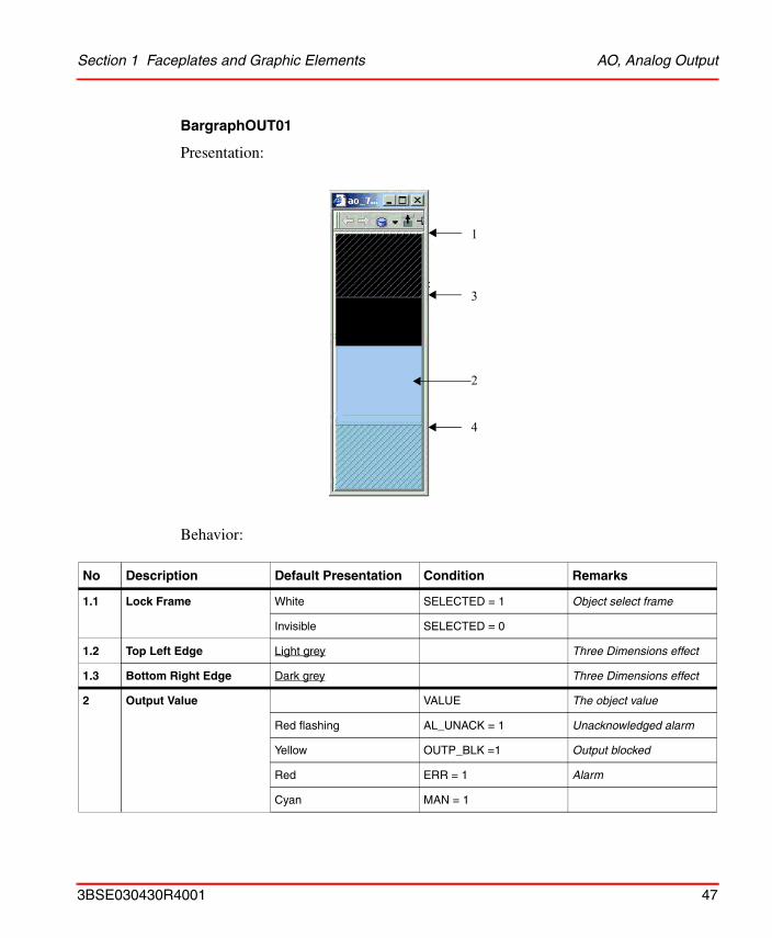
BargraphOUT01
Presentation:
Behavior:
No Description Default Presentation Condition Remarks
1.1 Lock Frame White SELECTED = 1 Object select frame
Invisible SELECTED = 0
1.2 Top Left Edge Light grey Three Dimensions effect
1.3 Bottom Right Edge Dark grey Three Dimensions effect
2 Output Value VALUE The object value
Red flashing AL_UNACK = 1 Unacknowledged alarm
Yellow OUTP_BLK =1 Output blocked
Red ERR = 1 Alarm
Cyan MAN = 1
1
2
3
4
3BSE030430R4001 47
AO, Analog Output Section 1 Faceplates and Graphic Elements
2 cont.
Magenta MAN = 0
3 High Limitation HI_LIM High limitation
HI_LIM > RANGEMAX or EN_HI = 0
Invisible
Yellow EN_HI = 1 and
VALUE_HI = 1
Grey EN_HI = 1
4 Low Limitation LO_LIM Low limitation
LO_LIM < RANGEMIN orEN_LO = 0
Invisible
Yellow EN_LO = 1 and
VALUE_LO = 1
Grey EN_LO = 1
No Description Default Presentation Condition Remarks
48 3BSE030430R4001
Section 1 Faceplates and Graphic Elements DI, Digital input
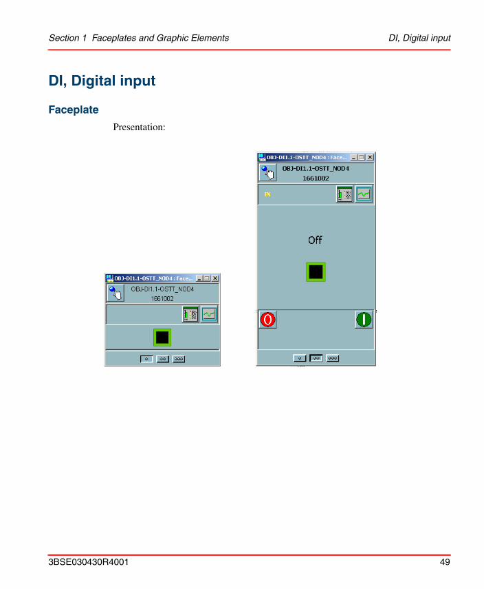
DI, Digital input
Faceplate
Presentation:
3BSE030430R4001 49
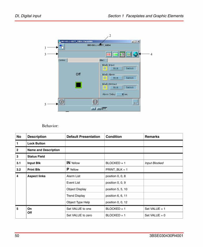
DI, Digital input Section 1 Faceplates and Graphic Elements
Behavior:
No Description Default Presentation Condition Remarks
1 Lock Button
2 Name and Description
3 Status Field
3.1 Input Blk IN Yellow BLOCKED = 1 Input Blocked
3.2 Print Blk P Yellow PRINT_BLK = 1
4 Aspect links Alarm List position 0, 0, 8
Event List position 0, 0, 9
Object Display position 5, 5, 10
Trend Display position 6, 6, 11
Object Type Help position 0, 0, 12
5 OnOff
Set VALUE to one BLOCKED = 1 Set VALUE = 1
Set VALUE to zero BLOCKED = 1 Set VALUE = 0
1
2
3
5
4
50 3BSE030430R4001
Section 1 Faceplates and Graphic Elements DI, Digital input
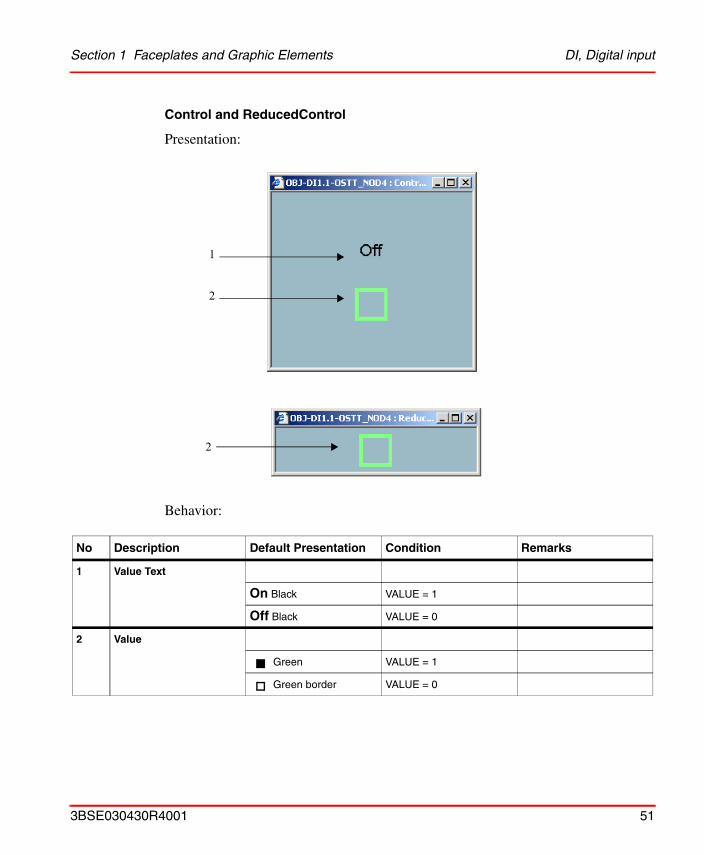
Control and ReducedControl
Presentation:
Behavior:
No Description Default Presentation Condition Remarks
1 Value Text
On Black VALUE = 1
Off Black VALUE = 0
2 Value
Green VALUE = 1
Green border VALUE = 0
1
2
2
3BSE030430R4001 51
DI, Digital input Section 1 Faceplates and Graphic Elements
Block
Presentation:
Behavior::
No Description Default Presentation Condition Remarks
1 Block Input Block Input Black
! Yellow Blocked
Block pressed BLOCKED = 1
Deblock pressed BLOCKED = 0
2 Block Alarm Block Alarm Black
! Yellow Blocked
Block pressed AL_BLK=1
Deblock pressed AL_BLK = 0
3 Block Printout Block Printout Black
! Yellow Blocked
Block pressed PR_BLK = 1
Deblock pressed PR_BLK=0
4.1 Alarm Delay Text Alarm Delay Black Text in front of the value
4.2 Alarm Delay Value Black ALARM_DELAY Alarm Delay value
1
2
3
4
52 3BSE030430R4001
Section 1 Faceplates and Graphic Elements DI, Digital input
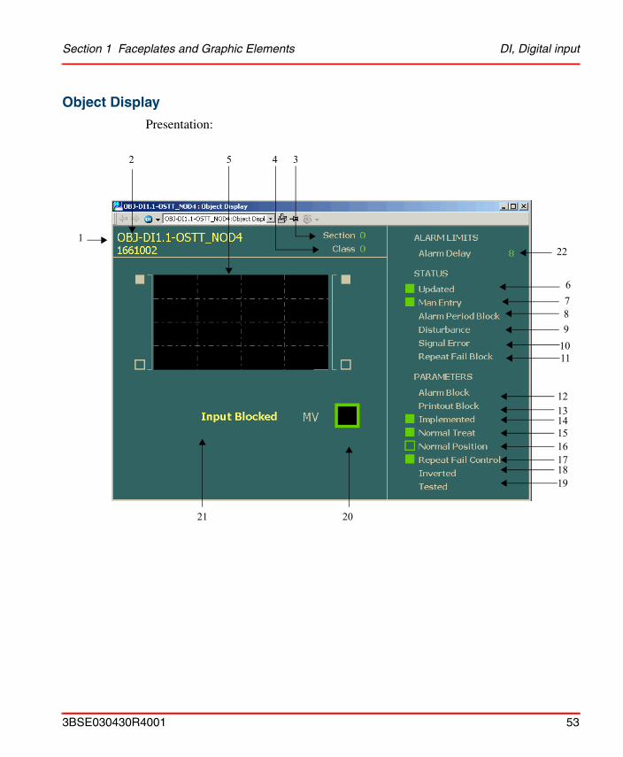
Object Display
Presentation:
1011
1213
1514
16171819
2021
5 4 3
1
2
6789
22
3BSE030430R4001 53
DI, Digital input Section 1 Faceplates and Graphic Elements
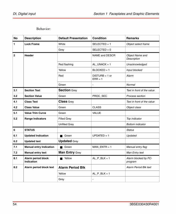
Behavior:
No Description Default Presentation Condition Remarks
1 Lock Frame White SELECTED = 1 Object select frame
Grey SELECTED = 0
2 Header NAME and DESCR Object Name and Description
Red flashing AL_UNACK = 1 Unacknowledged
Yellow BLOCKED = 1 Input blocked
Red DISTURB = 1 orERR = 1
Alarm
Green - Normal
3.1 Section Text Section Grey Text in front of the value
3.2 Section Value Green PROC_SEC Process section
4.1 Class Text Class Grey Text in front of the value
4.2 Class Value Green CLASS Object class
5.1 Value Trim Curve Green VALUE
5.2 Range Indicators Filled Grey Top indicator
Unfilled Grey Bottom indicator
6 STATUS Status
6.1 Updated Indication Green UPDATED = 1 Updated
6.2 Updated text Updated Grey
7.1 Manual entry Indication Green MAN_ENTR = 1 Manual entry flag
7.2 Manual entry text Man Entry Grey Man Entry text
8.1 Alarm period block Indication
Yellow AL_P_BLK = 1 Alarm blocked by PC-program
8.2 Alarm period block text Alarm Period Blk Alarm Period Blk text
Yellow AL_P_BLK = 1
Grey -
54 3BSE030430R4001
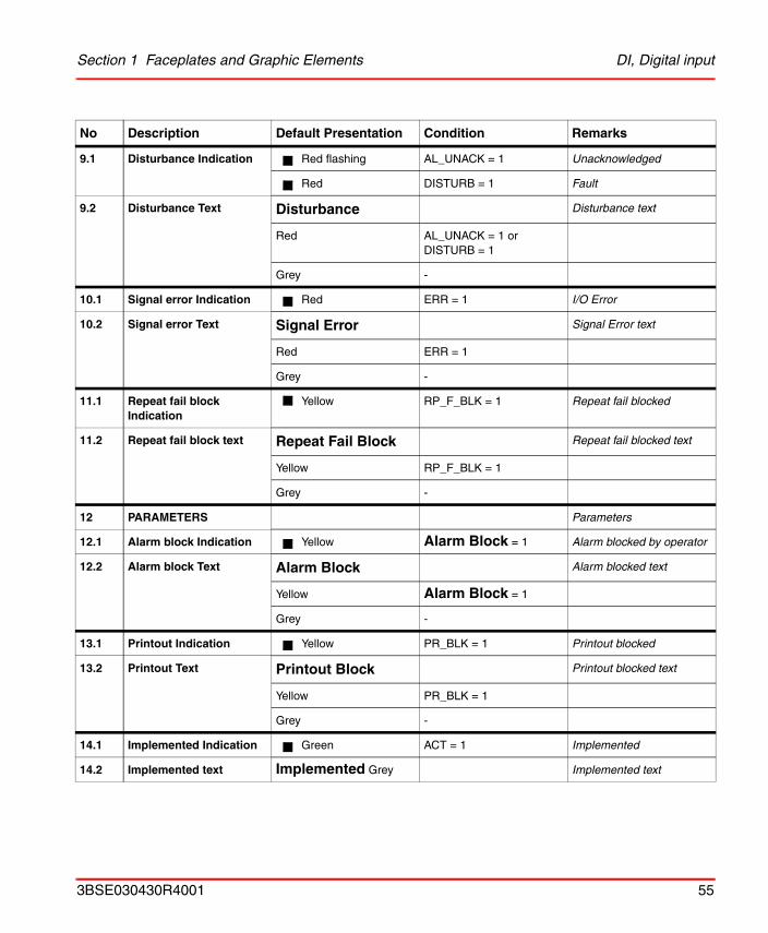
Section 1 Faceplates and Graphic Elements DI, Digital input
9.1 Disturbance Indication Red flashing AL_UNACK = 1 Unacknowledged
Red DISTURB = 1 Fault
9.2 Disturbance Text Disturbance Disturbance text
Red AL_UNACK = 1 or DISTURB = 1
Grey -
10.1 Signal error Indication Red ERR = 1 I/O Error
10.2 Signal error Text Signal Error Signal Error text
Red ERR = 1
Grey -
11.1 Repeat fail block Indication
Yellow RP_F_BLK = 1 Repeat fail blocked
11.2 Repeat fail block text Repeat Fail Block Repeat fail blocked text
Yellow RP_F_BLK = 1
Grey -
12 PARAMETERS Parameters
12.1 Alarm block Indication Yellow Alarm Block = 1 Alarm blocked by operator
12.2 Alarm block Text Alarm Block Alarm blocked text
Yellow Alarm Block = 1
Grey -
13.1 Printout Indication Yellow PR_BLK = 1 Printout blocked
13.2 Printout Text Printout Block Printout blocked text
Yellow PR_BLK = 1
Grey -
14.1 Implemented Indication Green ACT = 1 Implemented
14.2 Implemented text Implemented Grey Implemented text
No Description Default Presentation Condition Remarks
3BSE030430R4001 55
DI, Digital input Section 1 Faceplates and Graphic Elements
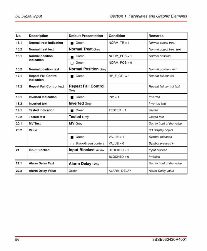
15.1 Normal treat Indication Green NORM_TR = 1 Normal object treat
15.2 Normal treat text Normal Treat Grey Normal object treat text
16.1 Normal position Indication
Green NORM_POS = 1 Normal position
Green NORM_POS = 0
16.2 Normal position text Normal Position Grey Normal position text
17.1 Repeat Fail Control Indication
Green RP_F_CTL = 1 Repeat fail control
17.2 Repeat Fail Control text Repeat Fail Control Grey
Repeat fail control text
18.1 Inverted Indication Green INV = 1 Inverted
18.2 Inverted text Inverted Grey Inverted text
19.1 Tested Indication Green TESTED = 1 Tested
19.2 Tested text Tested Grey Tested text
20.1 MV Text MV Grey Text in front of the value
20.2 Value 3D Display object
Green VALUE = 1 Symbol released
Black/Green borders VALUE = 0 Symbol pressed in
21 Input Blocked Input Blocked Yellow BLOCKED = 1 Input blocked
BLOCKED = 0 Invisible
22.1 Alarm Delay Text Alarm Delay Grey Text in front of the value
22.2 Alarm Delay Value Green ALARM_DELAY Alarm Delay value
No Description Default Presentation Condition Remarks
56 3BSE030430R4001
Section 1 Faceplates and Graphic Elements DI, Digital input
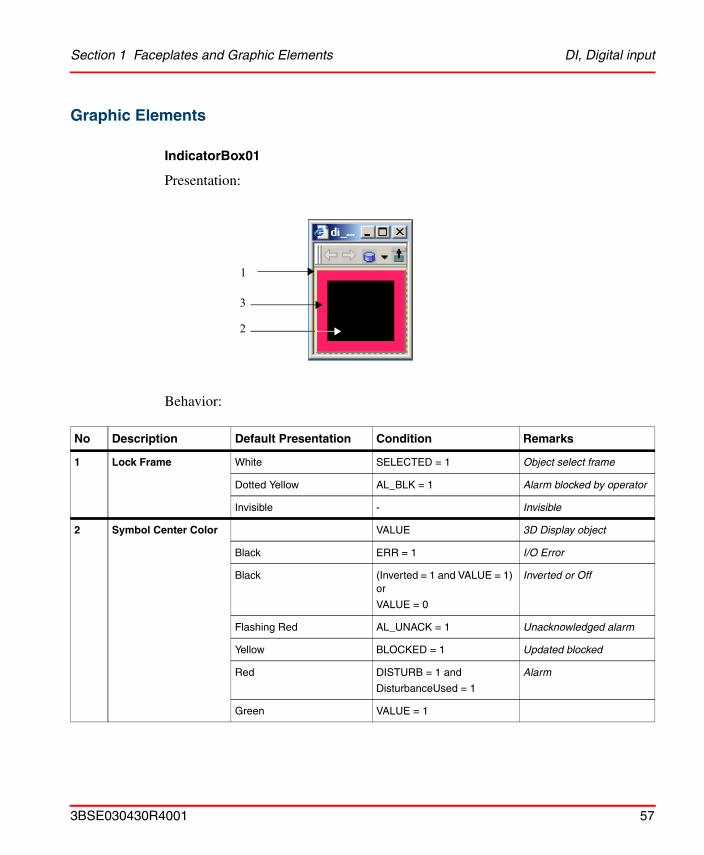
Graphic Elements
IndicatorBox01
Presentation:
Behavior:
No Description Default Presentation Condition Remarks
1 Lock Frame White SELECTED = 1 Object select frame
Dotted Yellow AL_BLK = 1 Alarm blocked by operator
Invisible - Invisible
2 Symbol Center Color VALUE 3D Display object
Black ERR = 1 I/O Error
Black (Inverted = 1 and VALUE = 1) or
VALUE = 0
Inverted or Off
Flashing Red AL_UNACK = 1 Unacknowledged alarm
Yellow BLOCKED = 1 Updated blocked
Red DISTURB = 1 and
DisturbanceUsed = 1
Alarm
Green VALUE = 1
3
1
2
3BSE030430R4001 57
DI, Digital input Section 1 Faceplates and Graphic Elements
Configuration:
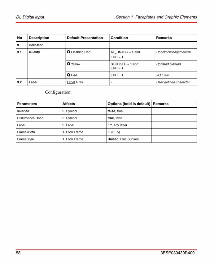
3 Indicator
3.1 Quality Q Flashing Red AL_UNACK = 1 and
ERR = 1
Unacknowledged alarm
Q Yellow BLOCKED = 1 and ERR = 1
Updated blocked
Q Red ERR = 1 I/O Error
3.2 Label Label Grey - User defined character
Parameters Affects Options (bold is default) Remarks
Inverted 2. Symbol false, true
Disturbance Used 2. Symbol true, false
Label 3. Label “ “, any letter
FrameWidth 1. Lock Frame 3, (0...5)
FrameStyle 1. Lock Frame Raised, Flat, Sunken
No Description Default Presentation Condition Remarks
58 3BSE030430R4001
Section 1 Faceplates and Graphic Elements DAT, Data Base Parameters
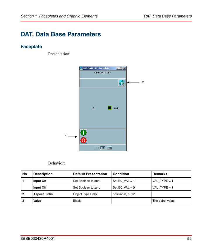
DAT, Data Base Parameters
Faceplate
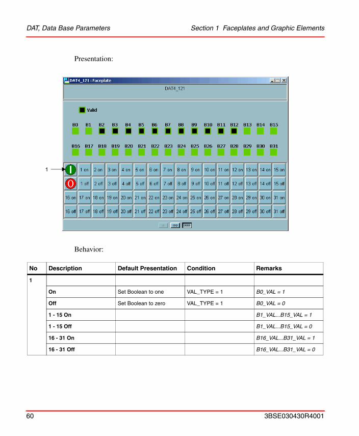
Presentation:
Behavior:
No Description Default Presentation Condition Remarks
1 Input On Set Boolean to one Set B0_VAL = 1 VAL_TYPE = 1
Input Off Set Boolean to zero Set B0_VAL = 0 VAL_TYPE = 1
2 Aspect Links Object Type Help position 0, 0, 12
3 Value Black The objrct value
1
2
3BSE030430R4001 59
DAT, Data Base Parameters Section 1 Faceplates and Graphic Elements
Presentation:
Behavior:
No Description Default Presentation Condition Remarks
1
On Set Boolean to one VAL_TYPE = 1 B0_VAL = 1
Off Set Boolean to zero VAL_TYPE = 1 B0_VAL = 0
1 - 15 On B1_VAL...B15_VAL = 1
1 - 15 Off B1_VAL...B15_VAL = 0
16 - 31 On B16_VAL...B31_VAL = 1
16 - 31 Off B16_VAL...B31_VAL = 0
1
60 3BSE030430R4001
Section 1 Faceplates and Graphic Elements DAT, Data Base Parameters
Presentation:
Behavior:
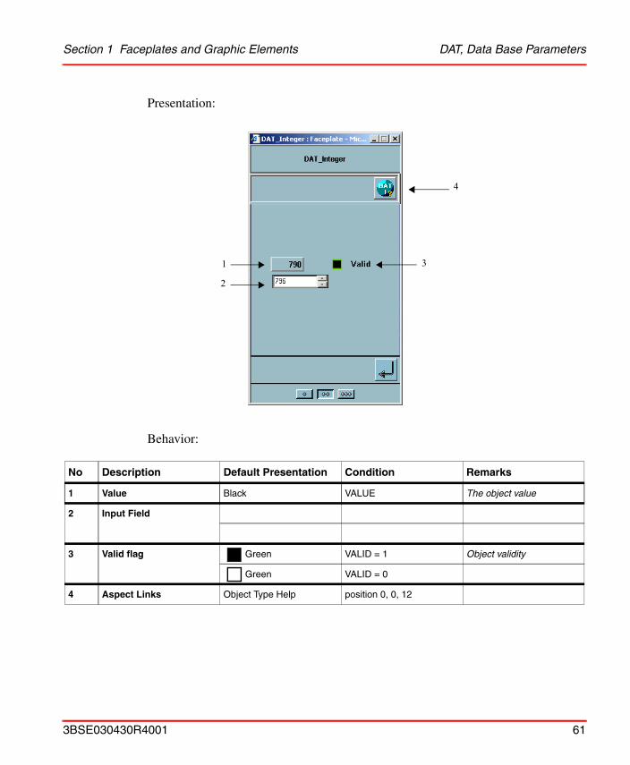
No Description Default Presentation Condition Remarks
1 Value Black VALUE The object value
2 Input Field
3 Valid flag Green VALID = 1 Object validity
Green VALID = 0
4 Aspect Links Object Type Help position 0, 0, 12
1
2
3
4
3BSE030430R4001 61
DAT, Data Base Parameters Section 1 Faceplates and Graphic Elements
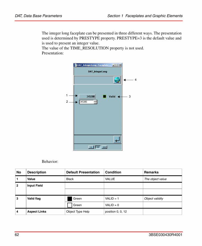
The integer long faceplate can be presented in three different ways. The presentation used is determined by PRESTYPE property. PRESTYPE=3 is the default value and is used to present an integer value. The value of the TIME_RESOLUTION property is not used.Presentation:
Behavior:
No Description Default Presentation Condition Remarks
1 Value Black VALUE The object value
2 Input Field
3 Valid flag Green VALID = 1 Object validity
Green VALID = 0
4 Aspect Links Object Type Help position 0, 0, 12
1
23
4
62 3BSE030430R4001
Section 1 Faceplates and Graphic Elements DAT, Data Base Parameters
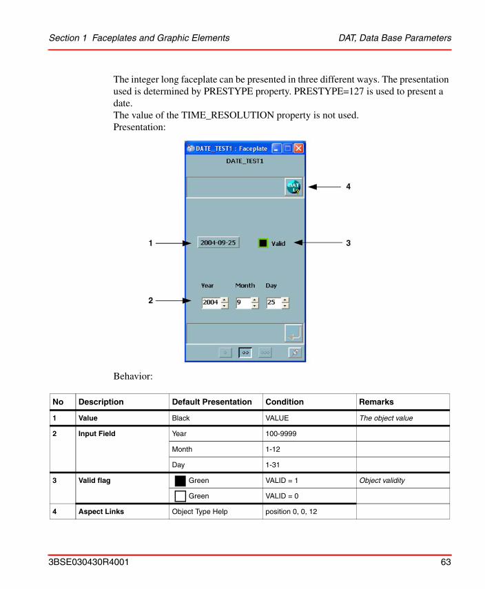
The integer long faceplate can be presented in three different ways. The presentation used is determined by PRESTYPE property. PRESTYPE=127 is used to present a date. The value of the TIME_RESOLUTION property is not used.Presentation:
Behavior:
No Description Default Presentation Condition Remarks
1 Value Black VALUE The object value
2 Input Field Year 100-9999
Month 1-12
Day 1-31
3 Valid flag Green VALID = 1 Object validity
Green VALID = 0
4 Aspect Links Object Type Help position 0, 0, 12
3BSE030430R4001 63
DAT, Data Base Parameters Section 1 Faceplates and Graphic Elements
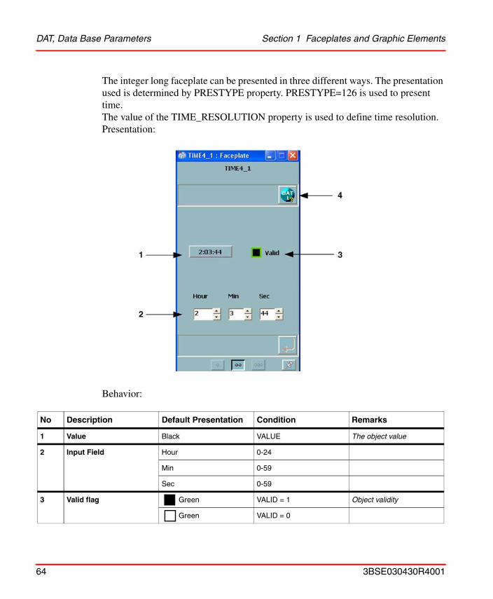
The integer long faceplate can be presented in three different ways. The presentation used is determined by PRESTYPE property. PRESTYPE=126 is used to present time. The value of the TIME_RESOLUTION property is used to define time resolution.Presentation:
Behavior:
No Description Default Presentation Condition Remarks
1 Value Black VALUE The object value
2 Input Field Hour 0-24
Min 0-59
Sec 0-59
3 Valid flag Green VALID = 1 Object validity
Green VALID = 0
64 3BSE030430R4001
Section 1 Faceplates and Graphic Elements DAT, Data Base Parameters
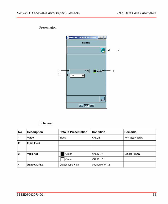
Presentation:
Behavior:
No Description Default Presentation Condition Remarks
1 Value Black VALUE The object value
2 Input Field
3 Valid flag Green VALID = 1 Object validity
Green VALID = 0
4 Aspect Links Object Type Help position 0, 0, 12
12
3
4
3BSE030430R4001 65
DAT, Data Base Parameters Section 1 Faceplates and Graphic Elements
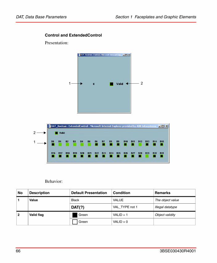
Control and ExtendedControl
Presentation:
Behavior:
No Description Default Presentation Condition Remarks
1 Value Black VALUE The object value
DAT(?) VAL_TYPE not 1 Illegal datatype
2 Valid flag Green VALID = 1 Object validity
Green VALID = 0
1 2
2
1
66 3BSE030430R4001
Section 1 Faceplates and Graphic Elements DAT, Data Base Parameters
Graphic Element
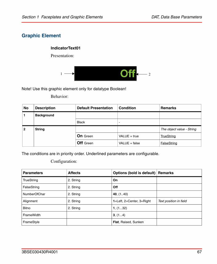
IndicatorText01
Presentation:
Note! Use this graphic element only for datatype Boolean!
Behavior:
The conditions are in priority order. Underlined parameters are configurable.
Configuration:
No Description Default Presentation Condition Remarks
1 Background
Black -
2 String The object value - String
On Green VALUE = true TrueString
Off Green VALUE = false FalseString
Parameters Affects Options (bold is default) Remarks
TrueString 2. String On
FalseString 2. String Off
NumberOfChar 2. String 40, (1..40)
Alignment 2. String 1=Left, 2=Center, 3=Right Text position in field
Bitno 2. String 1, (1...32)
FrameWidth 3, (1...4)
FrameStyle Flat, Raised, Sunken
1 2
3BSE030430R4001 67
DAT, Data Base Parameters Section 1 Faceplates and Graphic Elements
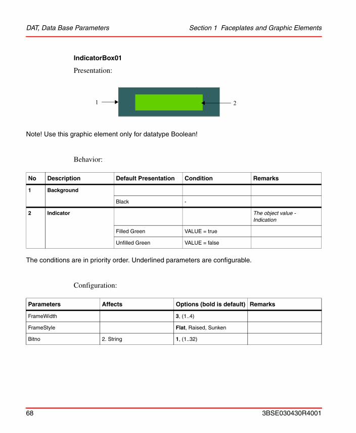
IndicatorBox01
Presentation:
Note! Use this graphic element only for datatype Boolean!
Behavior:
The conditions are in priority order. Underlined parameters are configurable.
Configuration:
No Description Default Presentation Condition Remarks
1 Background
Black -
2 Indicator The object value - Indication
Filled Green VALUE = true
Unfilled Green VALUE = false
Parameters Affects Options (bold is default) Remarks
FrameWidth 3, (1..4)
FrameStyle Flat, Raised, Sunken
Bitno 2. String 1, (1..32)
1 2
68 3BSE030430R4001
Section 1 Faceplates and Graphic Elements DAT, Data Base Parameters
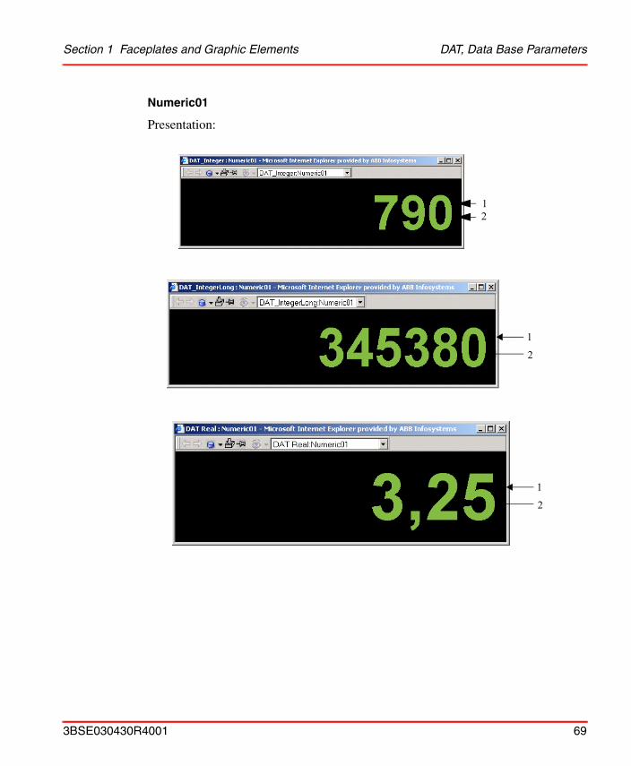
Numeric01
Presentation:
12
1
2
1
2
3BSE030430R4001 69
DAT, Data Base Parameters Section 1 Faceplates and Graphic Elements
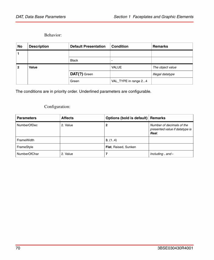
Behavior:
The conditions are in priority order. Underlined parameters are configurable.
Configuration:
No Description Default Presentation Condition Remarks
1
Black -
2 Value VALUE The object value
DAT(?) Green Illegal datatype
Green VAL_TYPE in range 2...4
Parameters Affects Options (bold is default) Remarks
NumberOfDec 2. Value 2 Number of decimals of the presented value if datatype is Real.
FrameWidth 3, (1..4)
FrameStyle Flat, Raised, Sunken
NumberOfChar 2. Value 7 Including . and -
70 3BSE030430R4001
Section 1 Faceplates and Graphic Elements DAT, Data Base Parameters
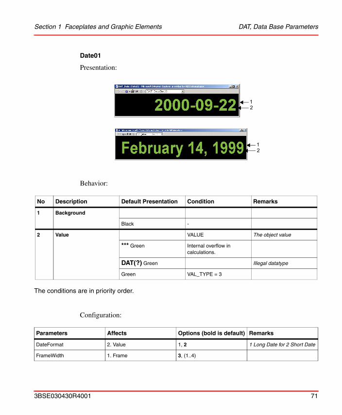
Date01
Presentation:
Behavior:
The conditions are in priority order.
Configuration:
No Description Default Presentation Condition Remarks
1 Background
Black -
2 Value VALUE The object value
*** Green Internal overflow in calculations.
DAT(?) Green Illegal datatype
Green VAL_TYPE = 3
Parameters Affects Options (bold is default) Remarks
DateFormat 2. Value 1, 2 1 Long Date for 2 Short Date
FrameWidth 1. Frame 3, (1..4)
12
12
3BSE030430R4001 71
DAT, Data Base Parameters Section 1 Faceplates and Graphic Elements
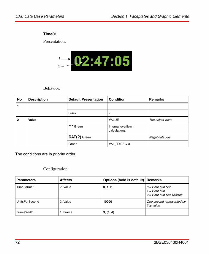
Time01
Presentation:
Behavior:
The conditions are in priority order.
Configuration:
No Description Default Presentation Condition Remarks
1
Black -
2 Value VALUE The object value
*** Green Internal overflow in calculations.
DAT(?) Green Illegal datatype
Green VAL_TYPE = 3
Parameters Affects Options (bold is default) Remarks
TimeFormat 2. Value 0, 1, 2 0 = Hour Min Sec1 = Hour Min 2 = Hour Min Sec Millisec
UnitsPerSecond 2. Value 10000 One second represented by this value
FrameWidth 1. Frame 3, (1..4)
2
1
72 3BSE030430R4001
Section 1 Faceplates and Graphic Elements DO, Digital output
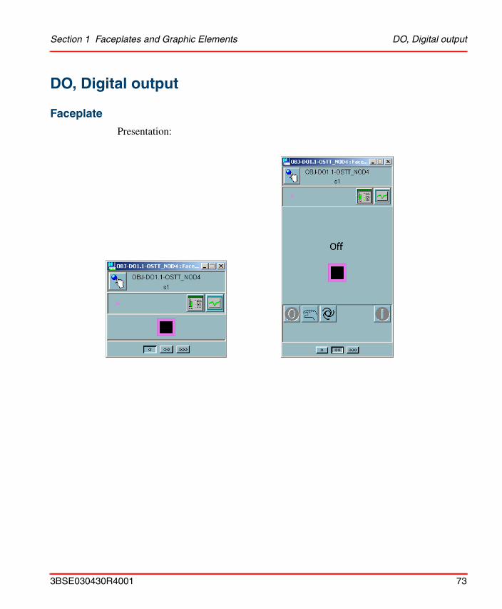
DO, Digital output
Faceplate
Presentation:
3BSE030430R4001 73
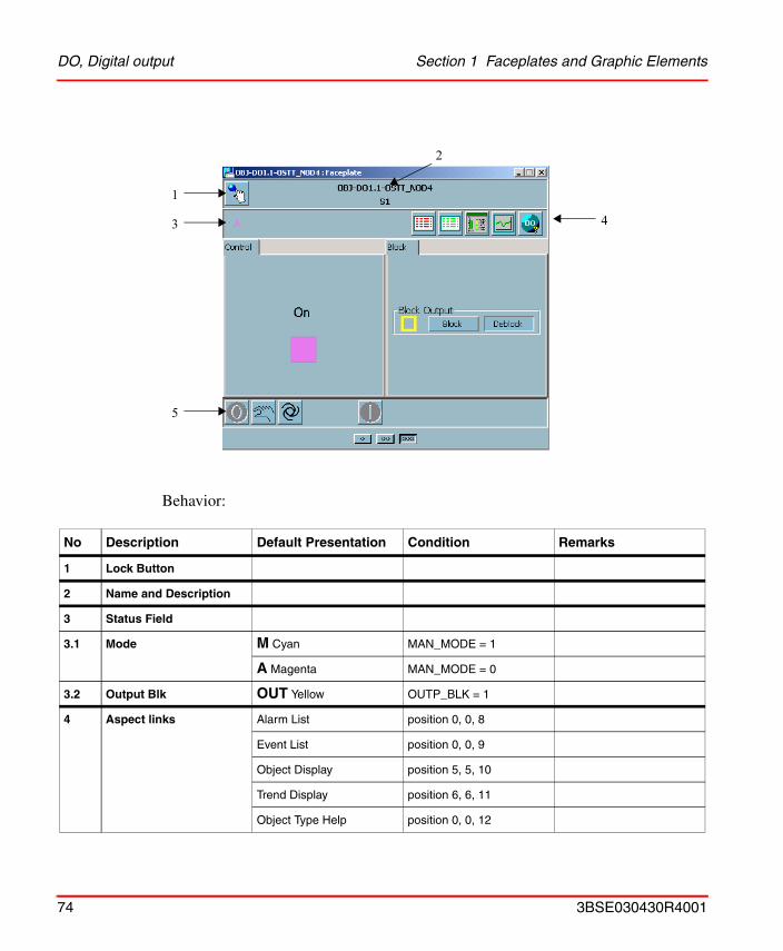
DO, Digital output Section 1 Faceplates and Graphic Elements
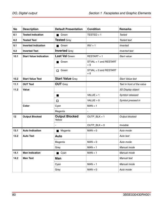
Behavior:
No Description Default Presentation Condition Remarks
1 Lock Button
2 Name and Description
3 Status Field
3.1 Mode M Cyan MAN_MODE = 1
A Magenta MAN_MODE = 0
3.2 Output Blk OUT Yellow OUTP_BLK = 1
4 Aspect links Alarm List position 0, 0, 8
Event List position 0, 0, 9
Object Display position 5, 5, 10
Trend Display position 6, 6, 11
Object Type Help position 0, 0, 12
1
3
2
4
5
74 3BSE030430R4001
Section 1 Faceplates and Graphic Elements DO, Digital output
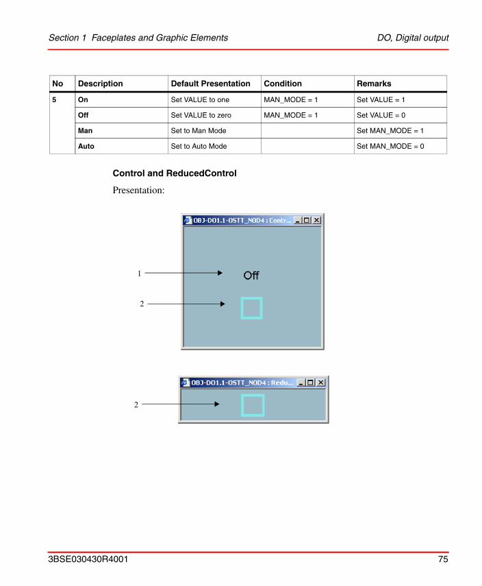
Control and ReducedControl
Presentation:
5 On Set VALUE to one MAN_MODE = 1 Set VALUE = 1
Off Set VALUE to zero MAN_MODE = 1 Set VALUE = 0
Man Set to Man Mode Set MAN_MODE = 1
Auto Set to Auto Mode Set MAN_MODE = 0
No Description Default Presentation Condition Remarks
1
2
2
3BSE030430R4001 75
DO, Digital output Section 1 Faceplates and Graphic Elements
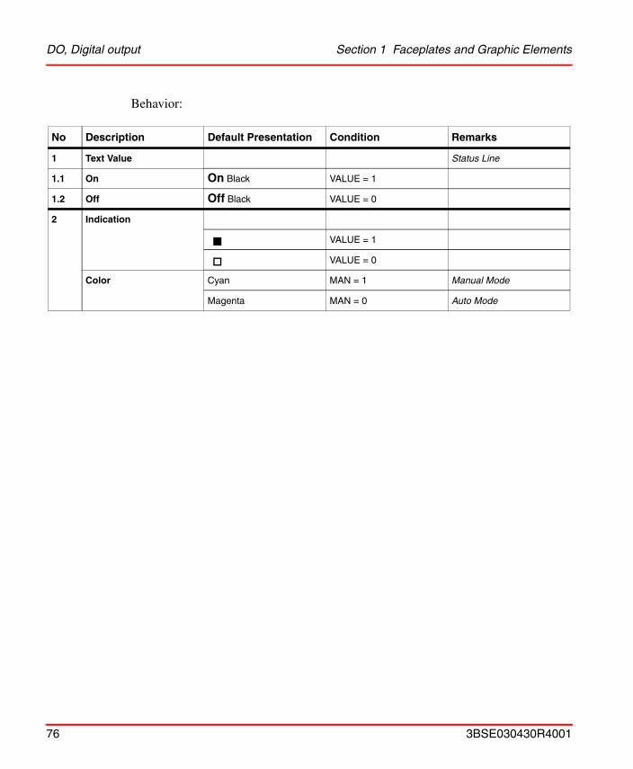
Behavior:
No Description Default Presentation Condition Remarks
1 Text Value Status Line
1.1 On On Black VALUE = 1
1.2 Off Off Black VALUE = 0
2 Indication
VALUE = 1
VALUE = 0
Color Cyan MAN = 1 Manual Mode
Magenta MAN = 0 Auto Mode
76 3BSE030430R4001
Section 1 Faceplates and Graphic Elements DO, Digital output
Block
Presentation:
Behavior:
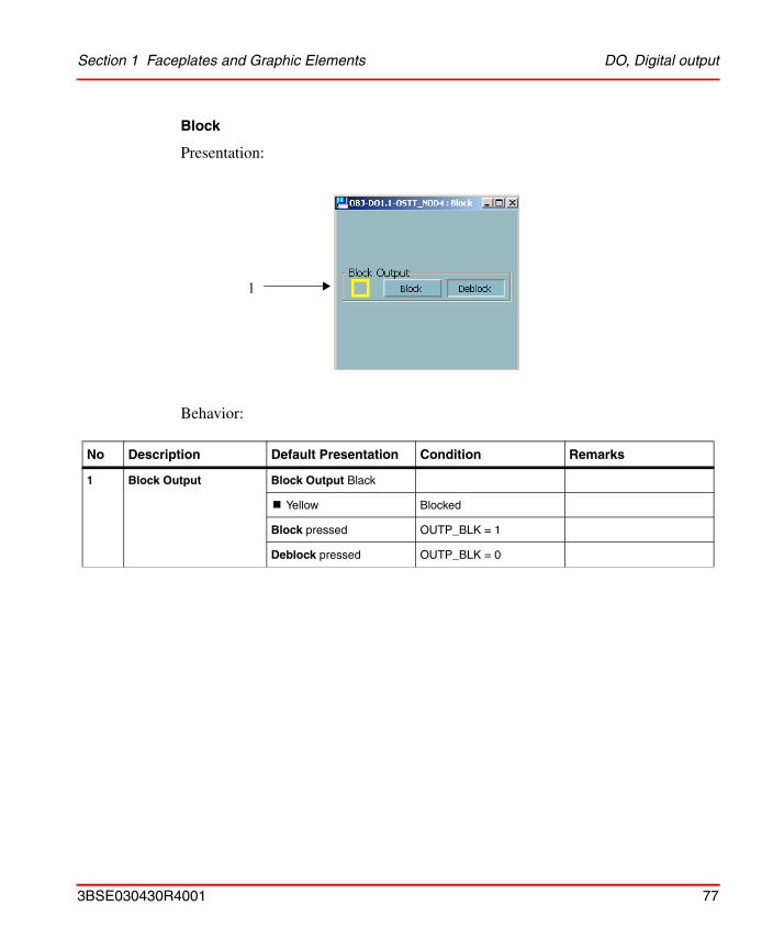
No Description Default Presentation Condition Remarks
1 Block Output Block Output Black
! Yellow Blocked
Block pressed OUTP_BLK = 1
Deblock pressed OUTP_BLK = 0
1
3BSE030430R4001 77
DO, Digital output Section 1 Faceplates and Graphic Elements
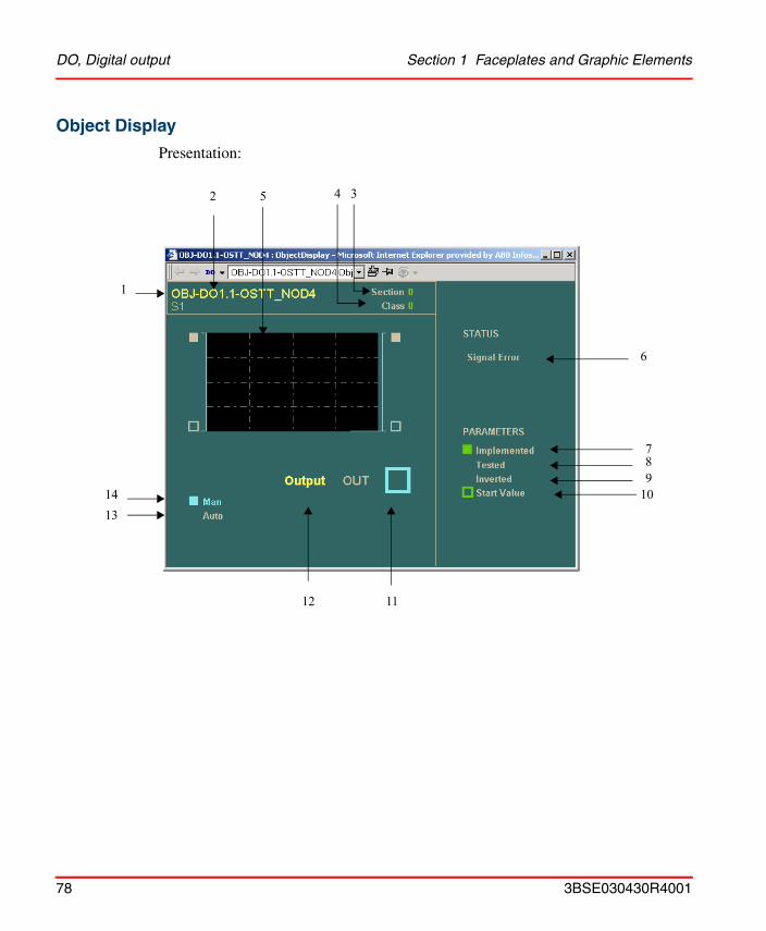
Object Display
Presentation:
5
6
78
10
1112
1413
4 3
9
2
1
78 3BSE030430R4001
Section 1 Faceplates and Graphic Elements DO, Digital output
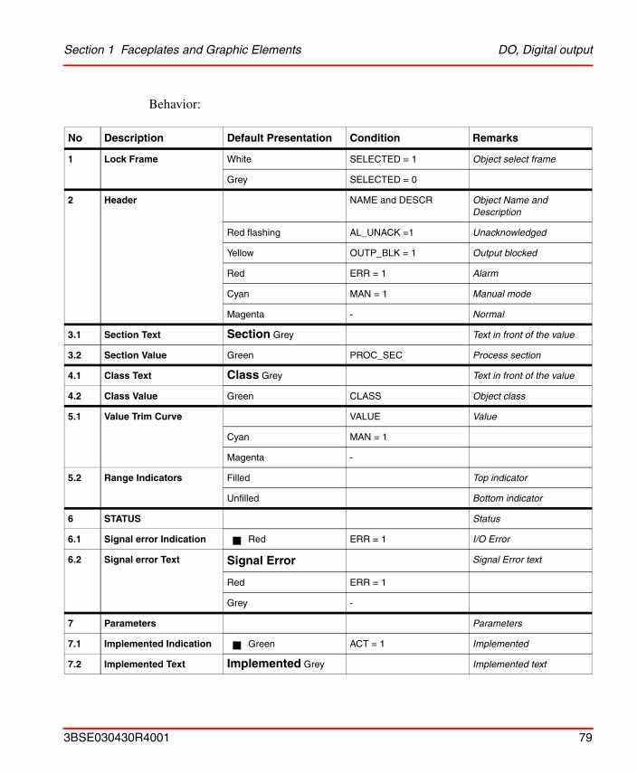
Behavior:
No Description Default Presentation Condition Remarks
1 Lock Frame White SELECTED = 1 Object select frame
Grey SELECTED = 0
2 Header NAME and DESCR Object Name and Description
Red flashing AL_UNACK =1 Unacknowledged
Yellow OUTP_BLK = 1 Output blocked
Red ERR = 1 Alarm
Cyan MAN = 1 Manual mode
Magenta - Normal
3.1 Section Text Section Grey Text in front of the value
3.2 Section Value Green PROC_SEC Process section
4.1 Class Text Class Grey Text in front of the value
4.2 Class Value Green CLASS Object class
5.1 Value Trim Curve VALUE Value
Cyan MAN = 1
Magenta -
5.2 Range Indicators Filled Top indicator
Unfilled Bottom indicator
6 STATUS Status
6.1 Signal error Indication Red ERR = 1 I/O Error
6.2 Signal error Text Signal Error Signal Error text
Red ERR = 1
Grey -
7 Parameters Parameters
7.1 Implemented Indication Green ACT = 1 Implemented
7.2 Implemented Text Implemented Grey Implemented text
3BSE030430R4001 79
DO, Digital output Section 1 Faceplates and Graphic Elements
8.1 Tested Indication Green TESTED = 1 Tested
8.2 Tested Text Tested Grey Tested text
9.1 Inverted Indication Green INV = 1 Inverted
9.2 Inverted Text Inverted Grey Inverted text
10.1 Start Value Indication Last Val Green RESTART = 1 Start value
Green STVAL = 1 and RESTART = 0
Green STVAL = 0 and RESTART = 0
10.2 Start Value Text Start Value Grey Start Value text
11.1 OUT Text OUT Grey Text in front of the value
11.2 Value 3D Display object
VALUE = 1 Symbol released
VALUE = 0 Symbol pressed in
Color Cyan MAN = 1
Magenta -
12 Output Blocked Output Blocked Yellow
OUTP_BLK = 1 Output blocked
- OUTP_BLK = 0 Invisible
13.1 Auto Indication Magenta MAN = 0 Auto mode
13.2 Auto Text Auto Auto text
Magenta MAN = 0 Auto mode
Grey MAN = 1 Manual mode
14.1 Man Indication Cyan MAN = 1 Manual mode
14.2 Man Text Man Manual text
Cyan MAN = 1 Manual mode
Grey MAN = 0 Auto mode
No Description Default Presentation Condition Remarks
80 3BSE030430R4001
Section 1 Faceplates and Graphic Elements DO, Digital output
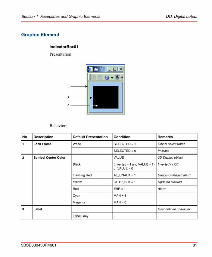
Graphic Element
IndicatorBox01
Presentation:
Behavior:
No Description Default Presentation Condition Remarks
1 Lock Frame White SELECTED = 1 Object select frame
SELECTED = 0 Invisible
2 Symbol Center Color VALUE 3D Display object
Black (Inverted = 1 and VALUE = 1) or VALUE = 0
Inverted or Off
Flashing Red AL_UNACK = 1 Unacknowledged alarm
Yellow OUTP_BLK = 1 Updated blocked
Red ERR = 1 Alarm
Cyan MAN = 1
Magenta MAN = 0
3 Label User defined character
Label Grey -
3
1
2
3BSE030430R4001 81
DO, Digital output Section 1 Faceplates and Graphic Elements
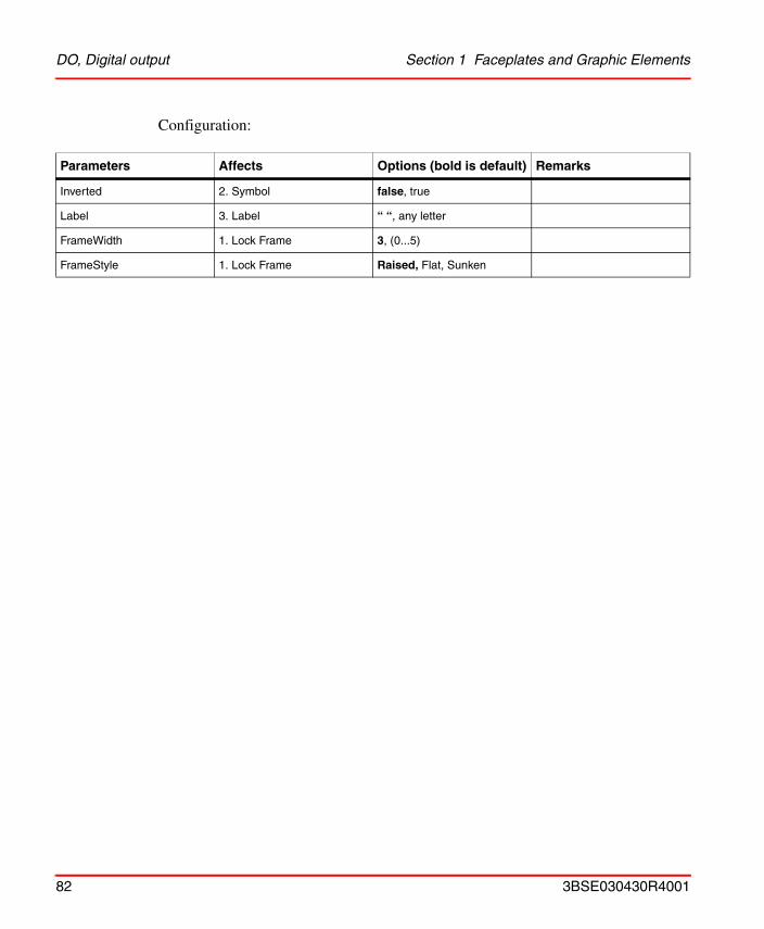
Configuration:
Parameters Affects Options (bold is default) Remarks
Inverted 2. Symbol false, true
Label 3. Label “ “, any letter
FrameWidth 1. Lock Frame 3, (0...5)
FrameStyle 1. Lock Frame Raised, Flat, Sunken
82 3BSE030430R4001
Section 1 Faceplates and Graphic Elements DRICONE, Engineered drive
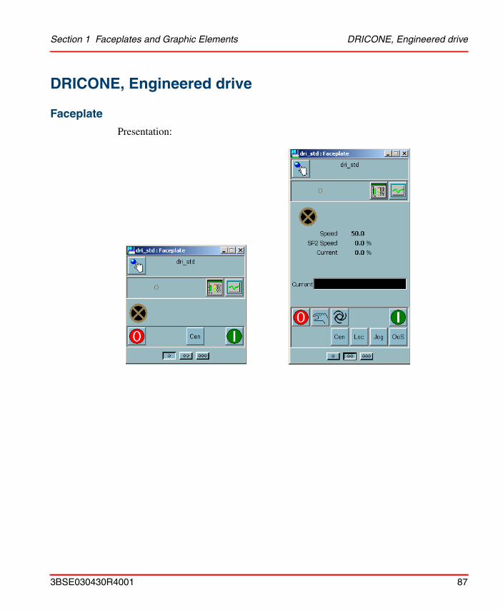
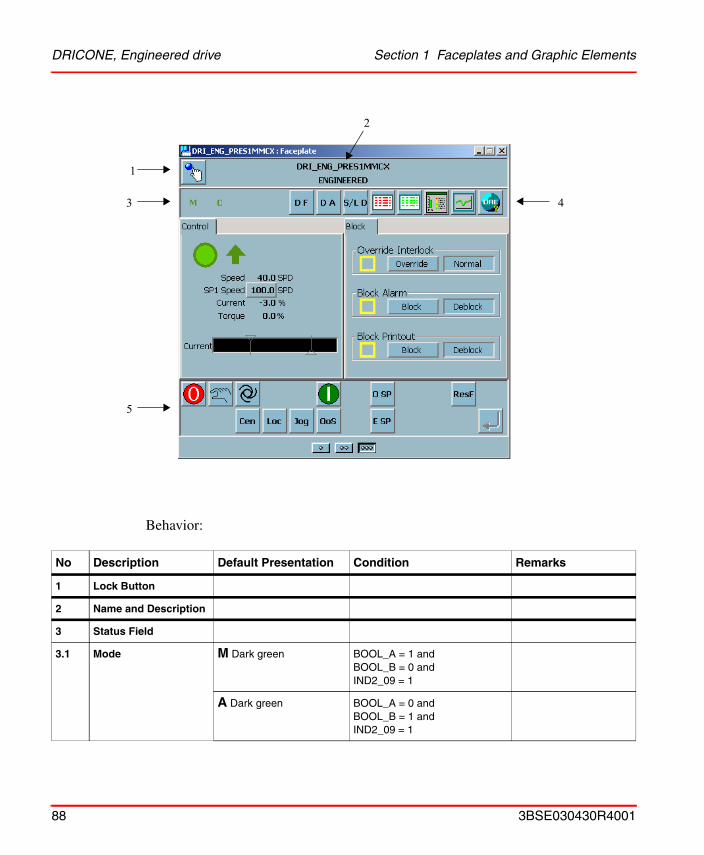
DRICONE, Engineered drive
Faceplate
Presentation:
3BSE030430R4001 87
DRICONE, Engineered drive Section 1 Faceplates and Graphic Elements
Behavior:
No Description Default Presentation Condition Remarks
1 Lock Button
2 Name and Description
3 Status Field
3.1 Mode M Dark green BOOL_A = 1 andBOOL_B = 0 andIND2_09 = 1
A Dark green BOOL_A = 0 andBOOL_B = 1 andIND2_09 = 1
1
3
5
4
2
88 3BSE030430R4001

Section 1 Faceplates and Graphic Elements DRICONE, Engineered drive
3.2 Control point O Light brown IND2_00 = 0 Out of service.
D Yellow IND2_09 = 0 Drive local
J Yellow IND2_09 = 1 andBOOL_C = 1
Jog running from motor place
L Dark green IND2_09 = 1 andBOOL_D = 1
Local controlled from local panel
C Dark green IND2_09 = 1 andBOOL_C = 0 andBOOL_D = 0
Central controlled from operator’s panel
3.3 Print Blk P Yellow PRINT_BLK = 1
3.4 Interlock indications X Yellow (IND2_12 = 1 and IND2_02 = 1 and BOOL_F = 1and IND2_15 = 0)or(IND2_13 = 1 and IND2_02 = 1 and BOOL_F = 1)
B- Interlock 3
B - Interlock 4
X Green (IND2_08 = 1) or(IND2_10 = 1 and IND2_15 = 0 ) orIND2_11 = 1 or(IND2_12 = 1 and BOOL_F = 0 and IND2_15 = 0 ) or(IND2_12 = 1 and IND2_02 = 0 and BOOL_F = 1and IND2_15 = 0) or(IND2_13 = 1 and BOOL_F = 0)or(IND2_13 = 1 and IND2_02 = 0 and BOOL_F = 1)orIND2_14 = 1
C - interlock
B - Interlock 1
B - Interlock 2
B- Interlock 3
B - Interlock 4
IA- Interlock
BX Red IND1_15 = 1 Override Interlock and Interlock active
BX Yellow (BOOL_C = 1 or IND2_15 = 1) and IND1_15=0
Override Interlock and Interlock active
No Description Default Presentation Condition Remarks
3BSE030430R4001 89
DRICONE, Engineered drive Section 1 Faceplates and Graphic Elements
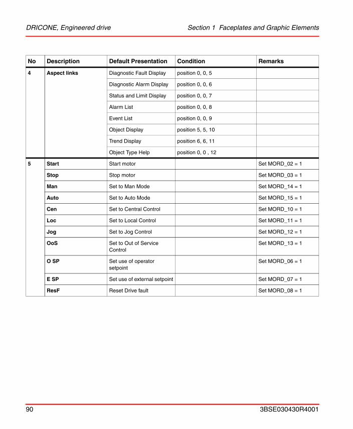
4 Aspect links Diagnostic Fault Display position 0, 0, 5
Diagnostic Alarm Display position 0, 0, 6
Status and Limit Display position 0, 0, 7
Alarm List position 0, 0, 8
Event List position 0, 0, 9
Object Display position 5, 5, 10
Trend Display position 6, 6, 11
Object Type Help position 0, 0 , 12
5 Start Start motor Set MORD_02 = 1
Stop Stop motor Set MORD_03 = 1
Man Set to Man Mode Set MORD_14 = 1
Auto Set to Auto Mode Set MORD_15 = 1
Cen Set to Central Control Set MORD_10 = 1
Loc Set to Local Control Set MORD_11 = 1
Jog Set to Jog Control Set MORD_12 = 1
OoS Set to Out of Service Control
Set MORD_13 = 1
O SP Set use of operator setpoint
Set MORD_06 = 1
E SP Set use of external setpoint Set MORD_07 = 1
ResF Reset Drive fault Set MORD_08 = 1
No Description Default Presentation Condition Remarks
90 3BSE030430R4001
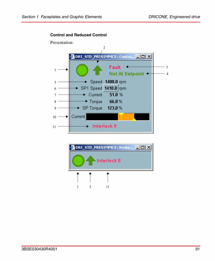
Section 1 Faceplates and Graphic Elements DRICONE, Engineered drive
Control and Reduced Control
Presentation:
1
5
6
7
8
9
10
11
3
4
2
2 111
3BSE030430R4001 91
DRICONE, Engineered drive Section 1 Faceplates and Graphic Elements
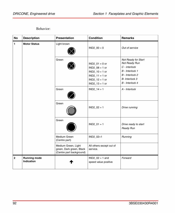
Behavior:
No Description Presentation Condition Remarks
1 Motor Status Light brown
IND2_00 = 0 Out of service
Green
IND2_01 = 0 or
IND2_08 = 1 or
IND2_10 = 1 or
IND2_11 = 1 or
IND2_12 = 1 or
IND2_13 = 1 or
Not Ready for StartNot Ready Run
C - interlock
B - Interlock 1
B - Interlock 2
B- Interlock 3
B - Interlock 4
Green IND2_14 = 1 A - Interlock
Green
IND2_02 = 1 Drive running
Green
IND2_01 = 1 Drive ready to start
Ready Run
Medium Green (Centre part)
IND2_02=1 Running
Medium Green, Light green, Dark green, Black (Centre part background)
All others except out of service.
2 Running mode Indication
IND2_02 = 1 and
speed value positive
Forward
92 3BSE030430R4001
Section 1 Faceplates and Graphic Elements DRICONE, Engineered drive
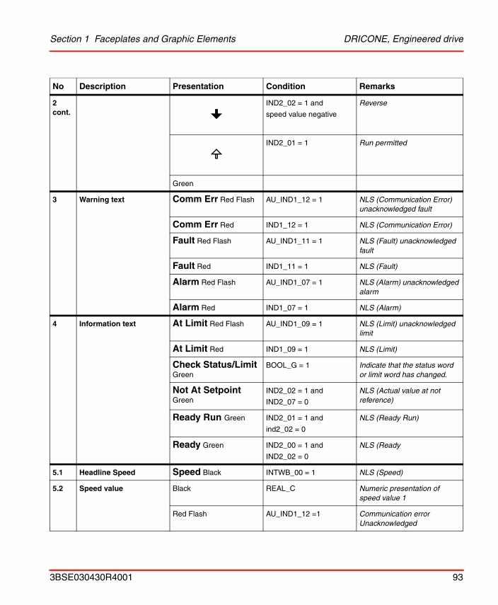
2 cont.
IND2_02 = 1 and
speed value negative
Reverse
IND2_01 = 1 Run permitted
Green
3 Warning text Comm Err Red Flash AU_IND1_12 = 1 NLS (Communication Error) unacknowledged fault
Comm Err Red IND1_12 = 1 NLS (Communication Error)
Fault Red Flash AU_IND1_11 = 1 NLS (Fault) unacknowledged fault
Fault Red IND1_11 = 1 NLS (Fault)
Alarm Red Flash AU_IND1_07 = 1 NLS (Alarm) unacknowledged alarm
Alarm Red IND1_07 = 1 NLS (Alarm)
4 Information text At Limit Red Flash AU_IND1_09 = 1 NLS (Limit) unacknowledged limit
At Limit Red IND1_09 = 1 NLS (Limit)
Check Status/Limit Green
BOOL_G = 1 Indicate that the status word or limit word has changed.
Not At Setpoint Green
IND2_02 = 1 and
IND2_07 = 0
NLS (Actual value at not reference)
Ready Run Green IND2_01 = 1 and
ind2_02 = 0
NLS (Ready Run)
Ready Green IND2_00 = 1 and
IND2_02 = 0
NLS (Ready
5.1 Headline Speed Speed Black INTWB_00 = 1 NLS (Speed)
5.2 Speed value Black REAL_C Numeric presentation of speed value 1
Red Flash AU_IND1_12 =1 Communication error Unacknowledged
No Description Presentation Condition Remarks
3BSE030430R4001 93
DRICONE, Engineered drive Section 1 Faceplates and Graphic Elements
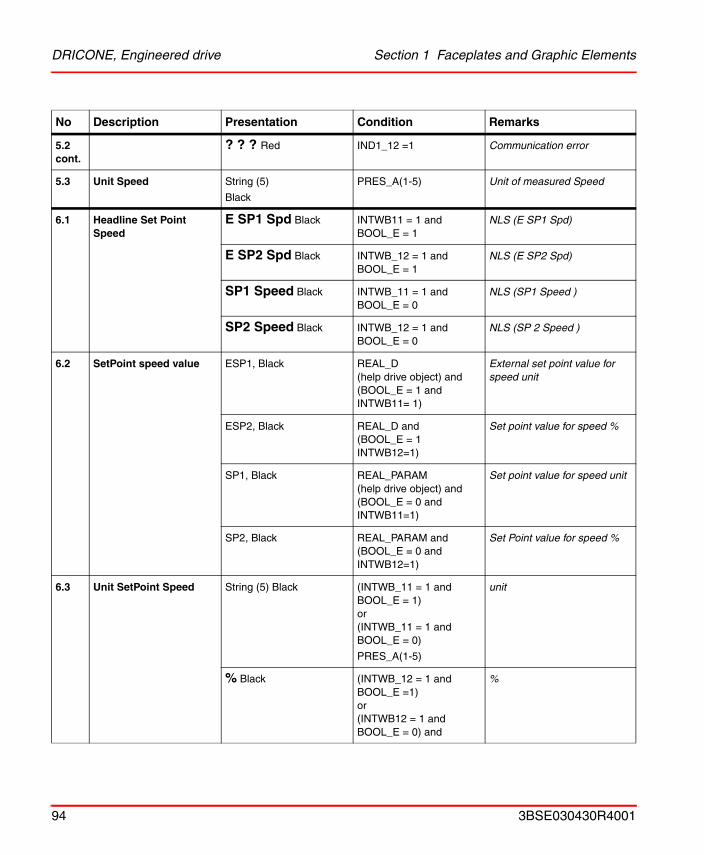
5.2 cont.
? ? ? Red IND1_12 =1 Communication error
5.3 Unit Speed String (5)
Black
PRES_A(1-5) Unit of measured Speed
6.1 Headline Set Point Speed
E SP1 Spd Black INTWB11 = 1 andBOOL_E = 1
NLS (E SP1 Spd)
E SP2 Spd Black INTWB_12 = 1 andBOOL_E = 1
NLS (E SP2 Spd)
SP1 Speed Black INTWB_11 = 1 andBOOL_E = 0
NLS (SP1 Speed )
SP2 Speed Black INTWB_12 = 1 and BOOL_E = 0
NLS (SP 2 Speed )
6.2 SetPoint speed value ESP1, Black REAL_D(help drive object) and(BOOL_E = 1 and INTWB11= 1)
External set point value for speed unit
ESP2, Black REAL_D and (BOOL_E = 1 INTWB12=1)
Set point value for speed %
SP1, Black REAL_PARAM(help drive object) and (BOOL_E = 0 and INTWB11=1)
Set point value for speed unit
SP2, Black REAL_PARAM and(BOOL_E = 0 and INTWB12=1)
Set Point value for speed %
6.3 Unit SetPoint Speed String (5) Black (INTWB_11 = 1 and BOOL_E = 1)or(INTWB_11 = 1 and BOOL_E = 0)
PRES_A(1-5)
unit
% Black (INTWB_12 = 1 and BOOL_E =1)or(INTWB12 = 1 and BOOL_E = 0) and
%
No Description Presentation Condition Remarks
94 3BSE030430R4001
Section 1 Faceplates and Graphic Elements DRICONE, Engineered drive
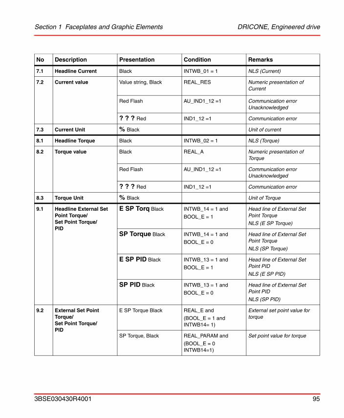
7.1 Headline Current Black INTWB_01 = 1 NLS (Current)
7.2 Current value Value string, Black REAL_RES Numeric presentation of Current
Red Flash AU_IND1_12 =1 Communication error Unacknowledged
? ? ? Red IND1_12 =1 Communication error
7.3 Current Unit % Black Unit of current
8.1 Headline Torque Black INTWB_02 = 1 NLS (Torque)
8.2 Torque value Black REAL_A Numeric presentation of Torque
Red Flash AU_IND1_12 =1 Communication error Unacknowledged
? ? ? Red IND1_12 =1 Communication error
8.3 Torque Unit % Black Unit of Torque
9.1 Headline External Set Point Torque/ Set Point Torque/PID
E SP Torq Black INTWB_14 = 1 and
BOOL_E = 1
Head line of External Set Point Torque
NLS (E SP Torque)
SP Torque Black INTWB_14 = 1 and
BOOL_E = 0
Head line of External Set Point Torque
NLS (SP Torque)
E SP PID Black INTWB_13 = 1 and
BOOL_E = 1
Head line of External Set Point PID
NLS (E SP PID)
SP PID Black INTWB_13 = 1 and
BOOL_E = 0
Head line of External Set Point PID
NLS (SP PID)
9.2 External Set Point Torque/ Set Point Torque/ PID
E SP Torque Black REAL_E and
(BOOL_E = 1 and INTWB14= 1)
External set point value for torque
SP Torque, Black REAL_PARAM and
(BOOL_E = 0 INTWB14=1)
Set point value for torque
No Description Presentation Condition Remarks
3BSE030430R4001 95
DRICONE, Engineered drive Section 1 Faceplates and Graphic Elements
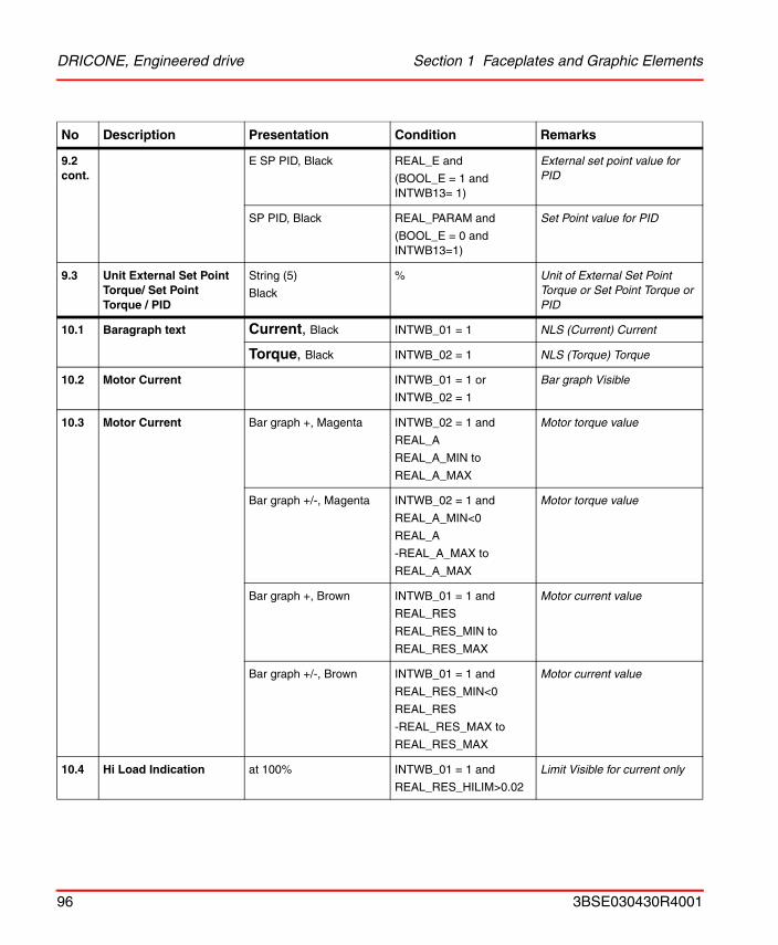
9.2 cont.
E SP PID, Black REAL_E and
(BOOL_E = 1 and INTWB13= 1)
External set point value for PID
SP PID, Black REAL_PARAM and
(BOOL_E = 0 and INTWB13=1)
Set Point value for PID
9.3 Unit External Set Point Torque/ Set Point Torque / PID
String (5)
Black
% Unit of External Set Point Torque or Set Point Torque or PID
10.1 Baragraph text Current, Black INTWB_01 = 1 NLS (Current) Current
Torque, Black INTWB_02 = 1 NLS (Torque) Torque
10.2 Motor Current INTWB_01 = 1 or
INTWB_02 = 1
Bar graph Visible
10.3 Motor Current Bar graph +, Magenta INTWB_02 = 1 and
REAL_A
REAL_A_MIN to
REAL_A_MAX
Motor torque value
Bar graph +/-, Magenta INTWB_02 = 1 and
REAL_A_MIN<0
REAL_A
-REAL_A_MAX to
REAL_A_MAX
Motor torque value
Bar graph +, Brown INTWB_01 = 1 and
REAL_RES
REAL_RES_MIN to
REAL_RES_MAX
Motor current value
Bar graph +/-, Brown INTWB_01 = 1 and
REAL_RES_MIN<0
REAL_RES
-REAL_RES_MAX to
REAL_RES_MAX
Motor current value
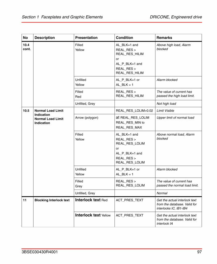
10.4 Hi Load Indication at 100% INTWB_01 = 1 and
REAL_RES_HILIM>0.02
Limit Visible for current only
No Description Presentation Condition Remarks
96 3BSE030430R4001
Section 1 Faceplates and Graphic Elements DRICONE, Engineered drive
10.4 cont.
Filled
Yellow
AL_BLK=1 and
REAL_RES > REAL_RES_HILIM
or
AL_P_BLK=1 and
REAL_RES > REAL_RES_HILIM
Above high load, Alarm blocked
Unfilled
Yellow
AL_P_BLK=1 or
AL_BLK = 1
Alarm blocked
Filled
Red
REAL_RES > REAL_RES_HILIM
The value of current has passed the high load limit.
Unfilled, Grey Not high load
10.5 Normal Load LimitIndicationNormal Load LimitIndication
REAL_RES_LOLIM>0.02 Limit Visible
Arrow (polygon) at REAL_RES_LOLIM
REAL_RES_MIN to
REAL_RES_MAX
Upper limit of normal load
Filled
Yellow
AL_BLK=1 and
REAL_RES > REAL_RES_LOLIM
or
AL_P_BLK=1 and
REAL_RES > REAL_RES_LOLIM
Above normal load, Alarm blocked
Unfilled
Yellow
AL_P_BLK=1 or
AL_BLK = 1
Alarm blocked
Filled
Grey
REAL_RES > REAL_RES_LOLIM
The value of current has passed the normal load limit.
Unfilled, Grey Normal
11 Blocking Interlock text Interlock text Red ACT_PRES_TEXT Get the actual interlock text from the database. Valid for interlocks IC, IB1-IB4
Interlock text Yellow ACT_PRES_TEXT Get the actual interlock text from the database. Valid for interlock IA
No Description Presentation Condition Remarks
3BSE030430R4001 97
DRICONE, Engineered drive Section 1 Faceplates and Graphic Elements
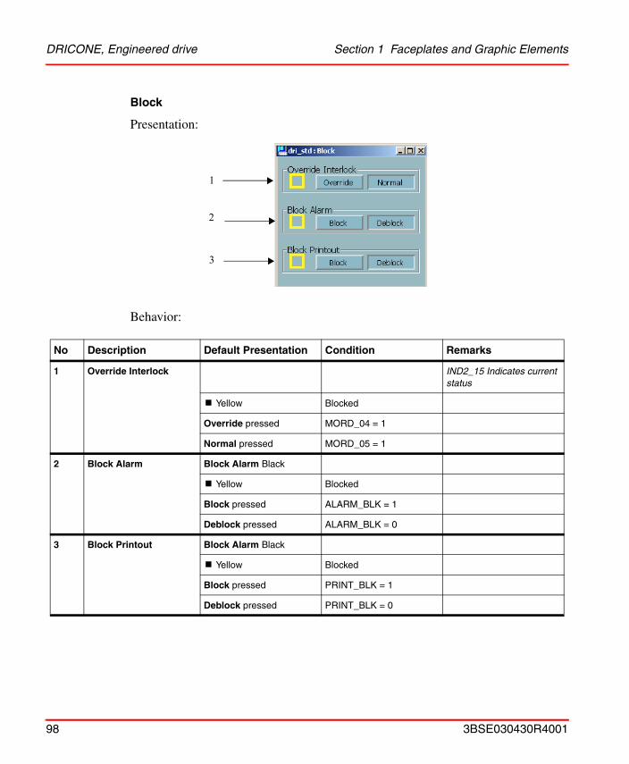
Block
Presentation:
Behavior:
No Description Default Presentation Condition Remarks
1 Override Interlock IND2_15 Indicates current status
! Yellow Blocked
Override pressed MORD_04 = 1
Normal pressed MORD_05 = 1
2 Block Alarm Block Alarm Black
! Yellow Blocked
Block pressed ALARM_BLK = 1
Deblock pressed ALARM_BLK = 0
3 Block Printout Block Alarm Black
! Yellow Blocked
Block pressed PRINT_BLK = 1
Deblock pressed PRINT_BLK = 0
1
3
2
98 3BSE030430R4001
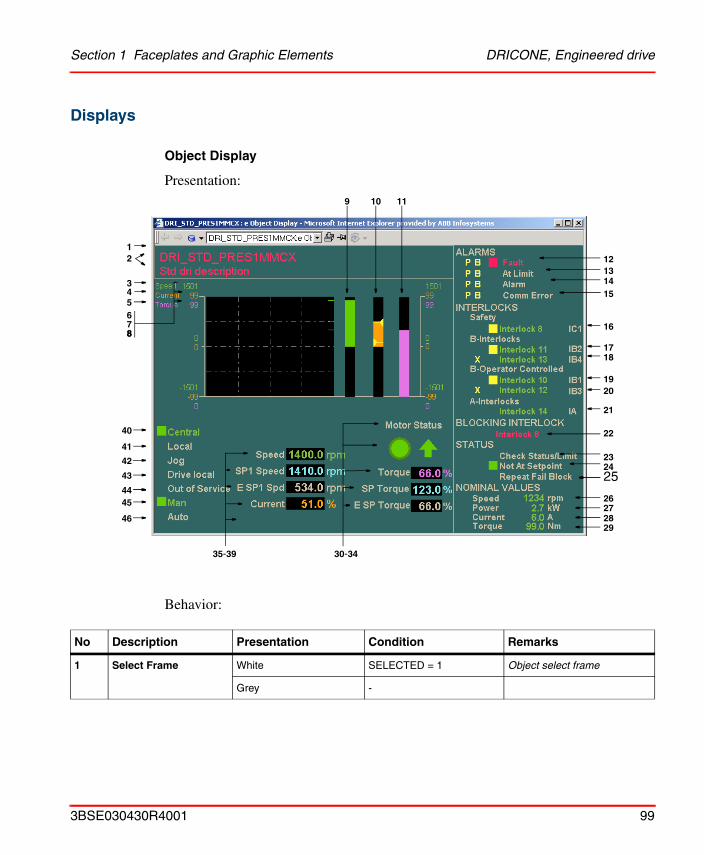
Section 1 Faceplates and Graphic Elements DRICONE, Engineered drive
Displays
Object Display
Presentation:
Behavior:
No Description Presentation Condition Remarks
1 Select Frame White SELECTED = 1 Object select frame
Grey -
10
121314
26272829
34
9 11
16
1718
21
20
24
30-34
15
22
25
23
45
42
40
41
35-39
1
65
78
19
2
8
44
46
43
3BSE030430R4001 99
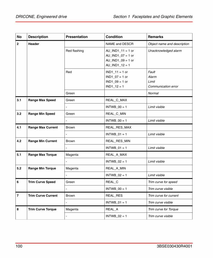
DRICONE, Engineered drive Section 1 Faceplates and Graphic Elements
2 Header NAME and DESCR Object name and description
Red flashing AU_IND1_11 = 1 or
AU_IND1_07 = 1 or
AU_IND1_09 = 1 or
AU_IND1_12 = 1
Unacknowledged alarm
Red IND1_11 = 1 or
IND1_07 = 1 or
IND1_09 = 1 or
IND1_12 = 1
Fault
Alarm
Limit
Communication error
Green Normal
3.1 Range Max Speed Green REAL_C_MAX
- INTWB_00 = 1 Limit visible
3.2 Range Min Speed Green REAL_C_MIN
- INTWB_00 = 1 Limit visible
4.1 Range Max Current Brown REAL_RES_MAX
- INTWB_01 = 1 Limit visible
4.2 Range Min Current Brown REAL_RES_MIN
- INTWB_01 = 1 Limit visible
5.1 Range Max Torque Magenta REAL_A_MAX
- INTWB_02 = 1 Limit visible
5.2 Range Min Torque Magenta REAL_A_MIN
- INTWB_02 = 1 Limit visible
6 Trim Curve Speed Green REAL_C Trim curve for speed
- INTWB_00 = 1 Trim curve visible
7 Trim Curve Current Brown REAL_RES Trim curve for current
- INTWB_01 = 1 Trim curve visible
8 Trim Curve Torque Magenta REAL_A Trim curve for Torque
- INTWB_02 = 1 Trim curve visible
No Description Presentation Condition Remarks
100 3BSE030430R4001
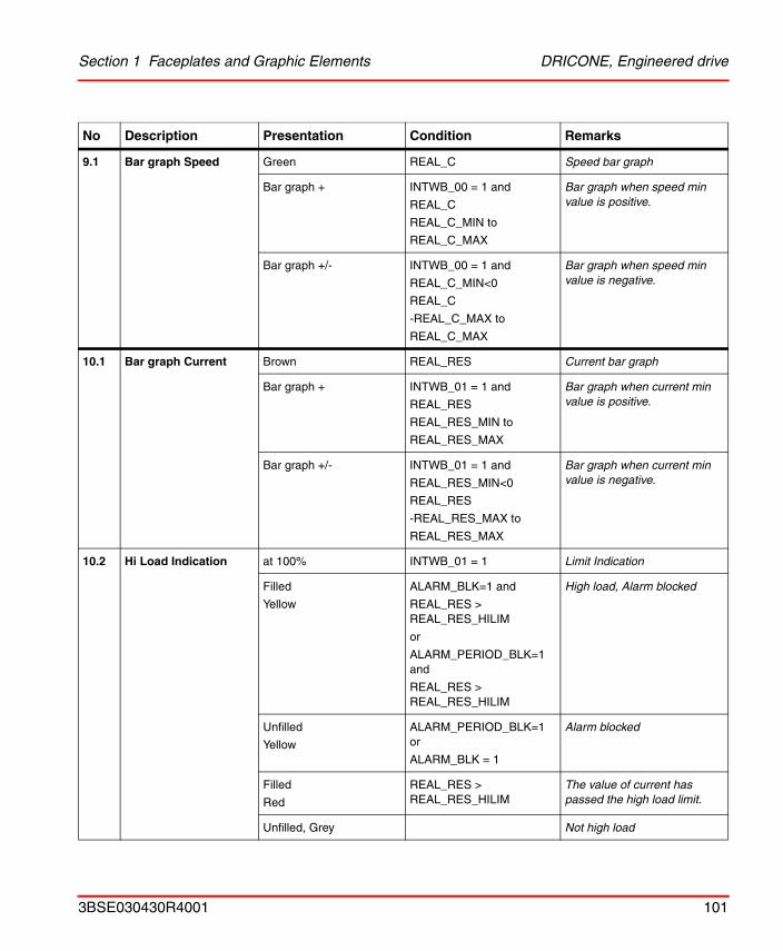
Section 1 Faceplates and Graphic Elements DRICONE, Engineered drive
9.1 Bar graph Speed Green REAL_C Speed bar graph
Bar graph + INTWB_00 = 1 and
REAL_C
REAL_C_MIN to
REAL_C_MAX
Bar graph when speed min value is positive.
Bar graph +/- INTWB_00 = 1 and
REAL_C_MIN<0
REAL_C
-REAL_C_MAX to
REAL_C_MAX
Bar graph when speed min value is negative.
10.1 Bar graph Current Brown REAL_RES Current bar graph
Bar graph + INTWB_01 = 1 and
REAL_RES
REAL_RES_MIN to
REAL_RES_MAX
Bar graph when current min value is positive.
Bar graph +/- INTWB_01 = 1 and
REAL_RES_MIN<0
REAL_RES
-REAL_RES_MAX to
REAL_RES_MAX
Bar graph when current min value is negative.
10.2 Hi Load Indication at 100% INTWB_01 = 1 Limit Indication
Filled
Yellow
ALARM_BLK=1 and
REAL_RES > REAL_RES_HILIM
or
ALARM_PERIOD_BLK=1 and
REAL_RES > REAL_RES_HILIM
High load, Alarm blocked
Unfilled
Yellow
ALARM_PERIOD_BLK=1 or
ALARM_BLK = 1
Alarm blocked
Filled
Red
REAL_RES > REAL_RES_HILIM
The value of current has passed the high load limit.
Unfilled, Grey Not high load
No Description Presentation Condition Remarks
3BSE030430R4001 101
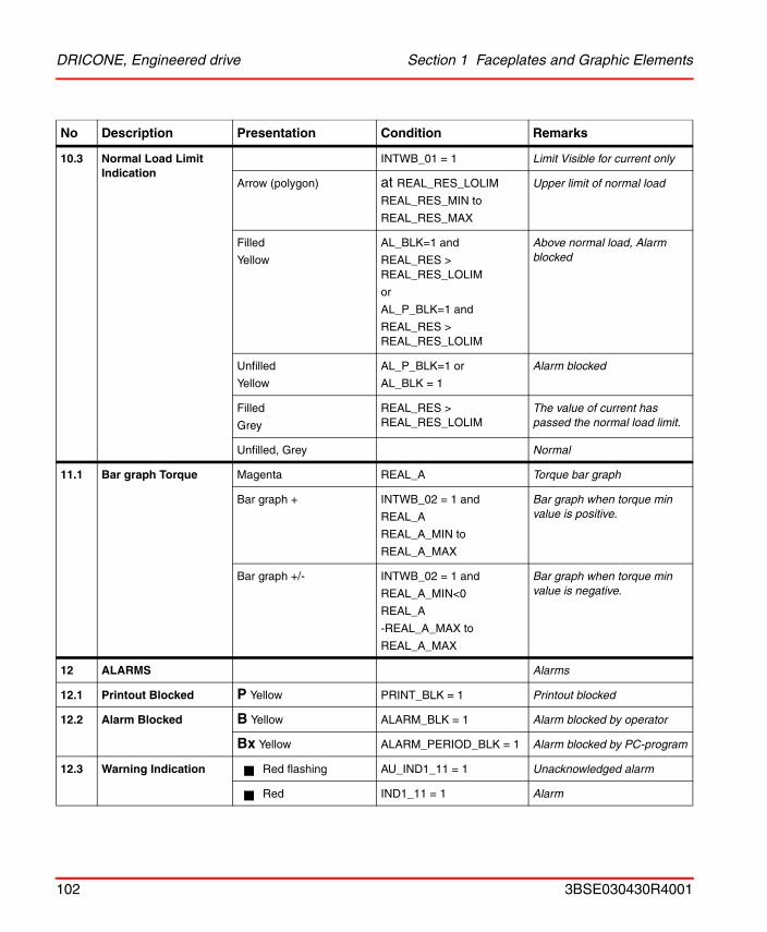
DRICONE, Engineered drive Section 1 Faceplates and Graphic Elements
10.3 Normal Load Limit Indication
INTWB_01 = 1 Limit Visible for current only
Arrow (polygon) at REAL_RES_LOLIM
REAL_RES_MIN to
REAL_RES_MAX
Upper limit of normal load
Filled
Yellow
AL_BLK=1 and
REAL_RES > REAL_RES_LOLIM
or
AL_P_BLK=1 and
REAL_RES > REAL_RES_LOLIM
Above normal load, Alarm blocked
Unfilled
Yellow
AL_P_BLK=1 or
AL_BLK = 1
Alarm blocked
Filled
Grey
REAL_RES > REAL_RES_LOLIM
The value of current has passed the normal load limit.
Unfilled, Grey Normal
11.1 Bar graph Torque Magenta REAL_A Torque bar graph
Bar graph + INTWB_02 = 1 and
REAL_A
REAL_A_MIN to
REAL_A_MAX
Bar graph when torque min value is positive.
Bar graph +/- INTWB_02 = 1 and
REAL_A_MIN<0
REAL_A
-REAL_A_MAX to
REAL_A_MAX
Bar graph when torque min value is negative.
12 ALARMS Alarms
12.1 Printout Blocked P Yellow PRINT_BLK = 1 Printout blocked
12.2 Alarm Blocked B Yellow ALARM_BLK = 1 Alarm blocked by operator
Bx Yellow ALARM_PERIOD_BLK = 1 Alarm blocked by PC-program
12.3 Warning Indication Red flashing AU_IND1_11 = 1 Unacknowledged alarm
Red IND1_11 = 1 Alarm
No Description Presentation Condition Remarks
102 3BSE030430R4001
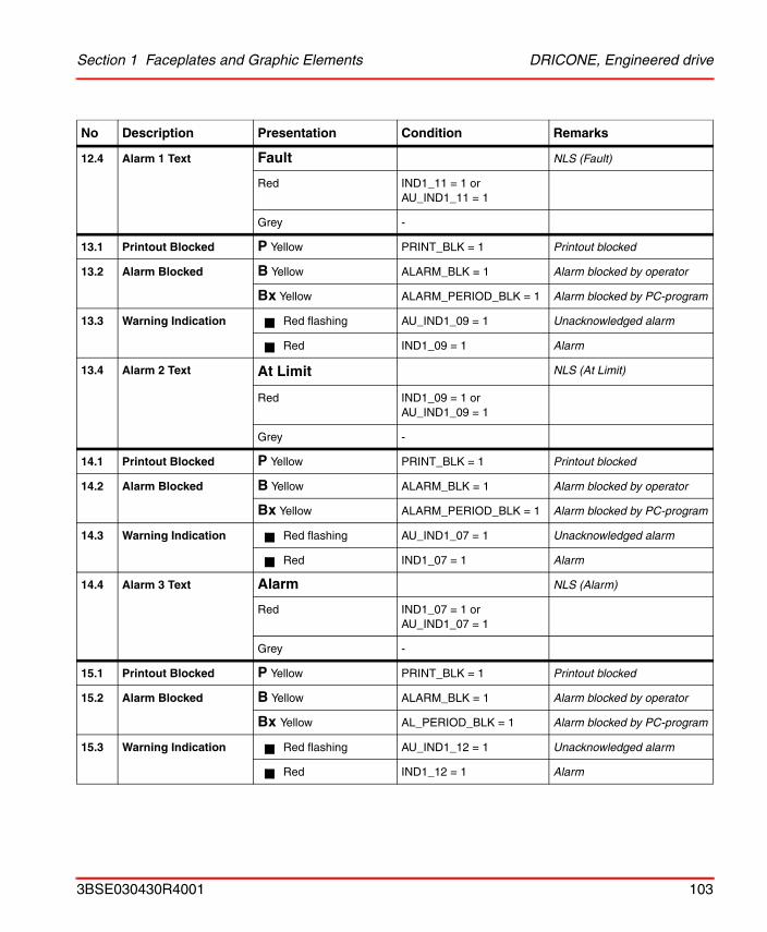
Section 1 Faceplates and Graphic Elements DRICONE, Engineered drive
12.4 Alarm 1 Text Fault NLS (Fault)
Red IND1_11 = 1 or AU_IND1_11 = 1
Grey -
13.1 Printout Blocked P Yellow PRINT_BLK = 1 Printout blocked
13.2 Alarm Blocked B Yellow ALARM_BLK = 1 Alarm blocked by operator
Bx Yellow ALARM_PERIOD_BLK = 1 Alarm blocked by PC-program
13.3 Warning Indication Red flashing AU_IND1_09 = 1 Unacknowledged alarm
Red IND1_09 = 1 Alarm
13.4 Alarm 2 Text At Limit NLS (At Limit)
Red IND1_09 = 1 or AU_IND1_09 = 1
Grey -
14.1 Printout Blocked P Yellow PRINT_BLK = 1 Printout blocked
14.2 Alarm Blocked B Yellow ALARM_BLK = 1 Alarm blocked by operator
Bx Yellow ALARM_PERIOD_BLK = 1 Alarm blocked by PC-program
14.3 Warning Indication Red flashing AU_IND1_07 = 1 Unacknowledged alarm
Red IND1_07 = 1 Alarm
14.4 Alarm 3 Text Alarm NLS (Alarm)
Red IND1_07 = 1 or AU_IND1_07 = 1
Grey -
15.1 Printout Blocked P Yellow PRINT_BLK = 1 Printout blocked
15.2 Alarm Blocked B Yellow ALARM_BLK = 1 Alarm blocked by operator
Bx Yellow AL_PERIOD_BLK = 1 Alarm blocked by PC-program
15.3 Warning Indication Red flashing AU_IND1_12 = 1 Unacknowledged alarm
Red IND1_12 = 1 Alarm
No Description Presentation Condition Remarks
3BSE030430R4001 103
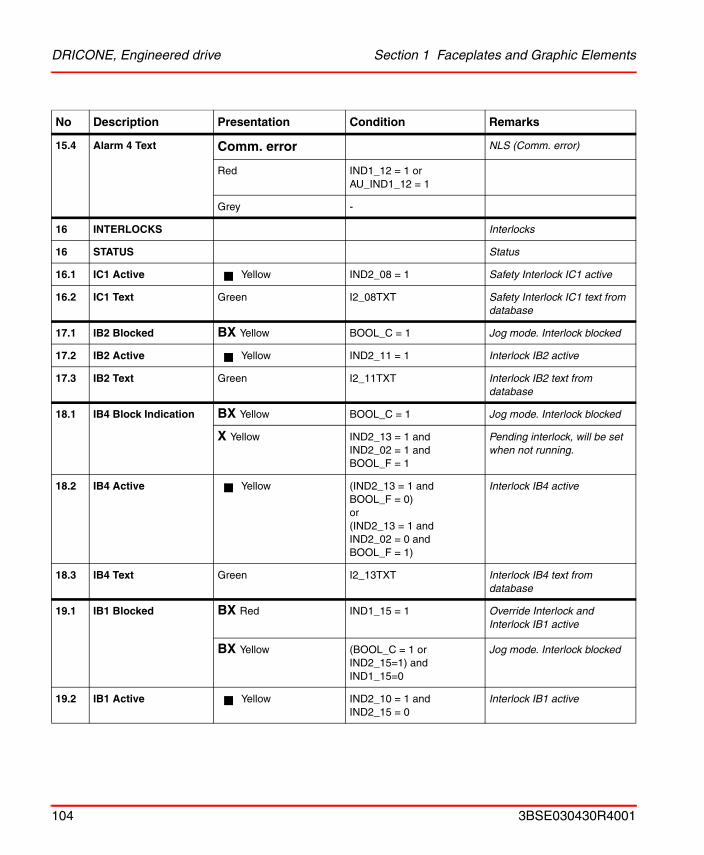
DRICONE, Engineered drive Section 1 Faceplates and Graphic Elements
15.4 Alarm 4 Text Comm. error NLS (Comm. error)
Red IND1_12 = 1 or AU_IND1_12 = 1
Grey -
16 INTERLOCKS Interlocks
16 STATUS Status
16.1 IC1 Active Yellow IND2_08 = 1 Safety Interlock IC1 active
16.2 IC1 Text Green I2_08TXT Safety Interlock IC1 text from database
17.1 IB2 Blocked BX Yellow BOOL_C = 1 Jog mode. Interlock blocked
17.2 IB2 Active Yellow IND2_11 = 1 Interlock IB2 active
17.3 IB2 Text Green I2_11TXT Interlock IB2 text from database
18.1 IB4 Block Indication BX Yellow BOOL_C = 1 Jog mode. Interlock blocked
X Yellow IND2_13 = 1 and IND2_02 = 1 and BOOL_F = 1
Pending interlock, will be set when not running.
18.2 IB4 Active Yellow (IND2_13 = 1 and BOOL_F = 0)or(IND2_13 = 1 and IND2_02 = 0 and BOOL_F = 1)
Interlock IB4 active
18.3 IB4 Text Green I2_13TXT Interlock IB4 text from database
19.1 IB1 Blocked BX Red IND1_15 = 1 Override Interlock and Interlock IB1 active
BX Yellow (BOOL_C = 1 or IND2_15=1) and IND1_15=0
Jog mode. Interlock blocked
19.2 IB1 Active Yellow IND2_10 = 1 and IND2_15 = 0
Interlock IB1 active
No Description Presentation Condition Remarks
104 3BSE030430R4001
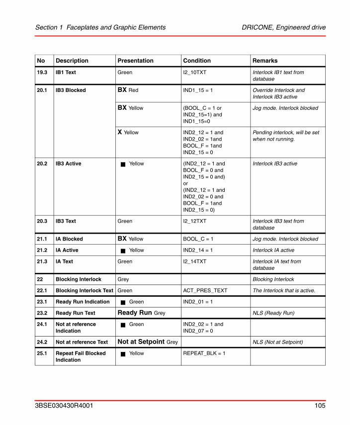
Section 1 Faceplates and Graphic Elements DRICONE, Engineered drive
19.3 IB1 Text Green I2_10TXT Interlock IB1 text from database
20.1 IB3 Blocked BX Red IND1_15 = 1 Override Interlock and Interlock IB3 active
BX Yellow (BOOL_C = 1 or IND2_15=1) and IND1_15=0
Jog mode. Interlock blocked
X Yellow IND2_12 = 1 and IND2_02 = 1and BOOL_F = 1and IND2_15 = 0
Pending interlock, will be set when not running.
20.2 IB3 Active Yellow (IND2_12 = 1 and BOOL_F = 0 and IND2_15 = 0 and)or(IND2_12 = 1 and IND2_02 = 0 and BOOL_F = 1and IND2_15 = 0)
Interlock IB3 active
20.3 IB3 Text Green I2_12TXT Interlock IB3 text from database
21.1 IA Blocked BX Yellow BOOL_C = 1 Jog mode. Interlock blocked
21.2 IA Active Yellow IND2_14 = 1 Interlock IA active
21.3 IA Text Green I2_14TXT Interlock IA text from database
22 Blocking Interlock Grey Blocking Interlock
22.1 Blocking Interlock Text Green ACT_PRES_TEXT The Interlock that is active.
23.1 Ready Run Indication Green IND2_01 = 1
23.2 Ready Run Text Ready Run Grey NLS (Ready Run)
24.1 Not at reference Indication
Green IND2_02 = 1 and IND2_07 = 0
24.2 Not at reference Text Not at Setpoint Grey NLS (Not at Setpoint)
25.1 Repeat Fail Blocked Indication
Yellow REPEAT_BLK = 1
No Description Presentation Condition Remarks
3BSE030430R4001 105
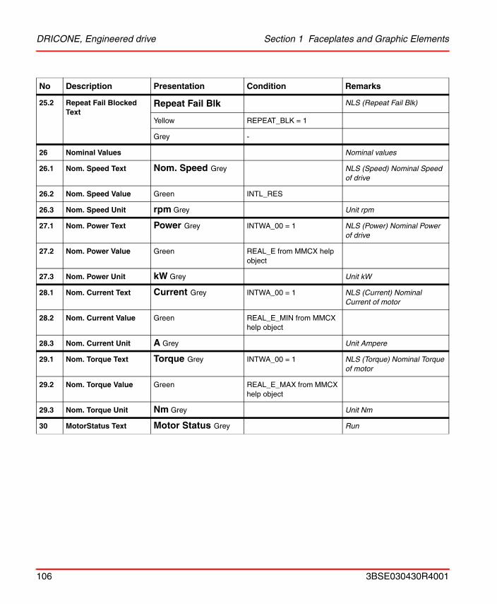
DRICONE, Engineered drive Section 1 Faceplates and Graphic Elements
25.2 Repeat Fail Blocked Text
Repeat Fail Blk NLS (Repeat Fail Blk)
Yellow REPEAT_BLK = 1
Grey -
26 Nominal Values Nominal values
26.1 Nom. Speed Text Nom. Speed Grey NLS (Speed) Nominal Speed of drive
26.2 Nom. Speed Value Green INTL_RES
26.3 Nom. Speed Unit rpm Grey Unit rpm
27.1 Nom. Power Text Power Grey INTWA_00 = 1 NLS (Power) Nominal Power of drive
27.2 Nom. Power Value Green REAL_E from MMCX help object
27.3 Nom. Power Unit kW Grey Unit kW
28.1 Nom. Current Text Current Grey INTWA_00 = 1 NLS (Current) Nominal Current of motor
28.2 Nom. Current Value Green REAL_E_MIN from MMCX help object
28.3 Nom. Current Unit A Grey Unit Ampere
29.1 Nom. Torque Text Torque Grey INTWA_00 = 1 NLS (Torque) Nominal Torque of motor
29.2 Nom. Torque Value Green REAL_E_MAX from MMCX help object
29.3 Nom. Torque Unit Nm Grey Unit Nm
30 MotorStatus Text Motor Status Grey Run
No Description Presentation Condition Remarks
106 3BSE030430R4001
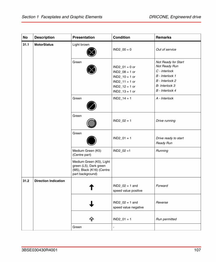
Section 1 Faceplates and Graphic Elements DRICONE, Engineered drive
31.1 MotorStatus Light brown
IND2_00 = 0 Out of service
Green
IND2_01 = 0 or
IND2_08 = 1 or
IND2_10 = 1 or
IND2_11 = 1 or
IND2_12 = 1 or
IND2_13 = 1 or
Not Ready for StartNot Ready Run
C - interlock
B - Interlock 1
B - Interlock 2
B- Interlock 3
B - Interlock 4
Green IND2_14 = 1 A - Interlock
Green
IND2_02 = 1 Drive running
Green
IND2_01 = 1 Drive ready to start
Ready Run
Medium Green (K5) (Centre part)
IND2_02 =1 Running
Medium Green (K5), Light green (L5), Dark green (M5), Black (K16) (Centre part background)
31.2 Direction Indication
IND2_02 = 1 and
speed value positive
Forward
IND2_02 = 1 and
speed value negative
Reverse
IND2_01 = 1 Run permitted
Green -
No Description Presentation Condition Remarks
3BSE030430R4001 107
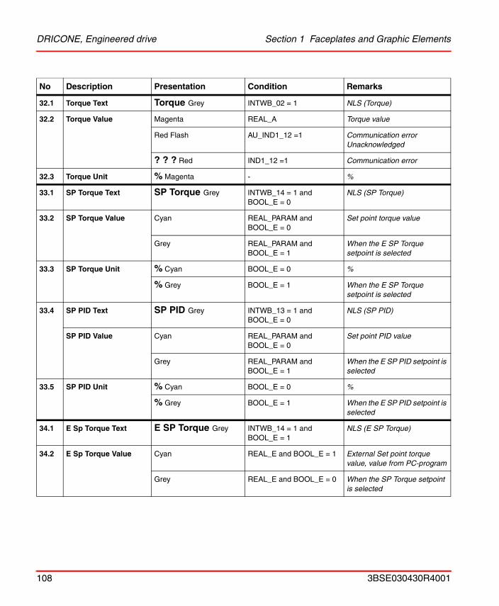
DRICONE, Engineered drive Section 1 Faceplates and Graphic Elements
32.1 Torque Text Torque Grey INTWB_02 = 1 NLS (Torque)
32.2 Torque Value Magenta REAL_A Torque value
Red Flash AU_IND1_12 =1 Communication error Unacknowledged
? ? ? Red IND1_12 =1 Communication error
32.3 Torque Unit % Magenta - %
33.1 SP Torque Text SP Torque Grey INTWB_14 = 1 and BOOL_E = 0
NLS (SP Torque)
33.2 SP Torque Value Cyan REAL_PARAM and BOOL_E = 0
Set point torque value
Grey REAL_PARAM and BOOL_E = 1
When the E SP Torque setpoint is selected
33.3 SP Torque Unit % Cyan BOOL_E = 0 %
% Grey BOOL_E = 1 When the E SP Torque setpoint is selected
33.4 SP PID Text SP PID Grey INTWB_13 = 1 and BOOL_E = 0
NLS (SP PID)
SP PID Value Cyan REAL_PARAM and BOOL_E = 0
Set point PID value
Grey REAL_PARAM and BOOL_E = 1
When the E SP PID setpoint is selected
33.5 SP PID Unit % Cyan BOOL_E = 0 %
% Grey BOOL_E = 1 When the E SP PID setpoint is selected
34.1 E Sp Torque Text E SP Torque Grey INTWB_14 = 1 and BOOL_E = 1
NLS (E SP Torque)
34.2 E Sp Torque Value Cyan REAL_E and BOOL_E = 1 External Set point torque value, value from PC-program
Grey REAL_E and BOOL_E = 0 When the SP Torque setpoint is selected
No Description Presentation Condition Remarks
108 3BSE030430R4001
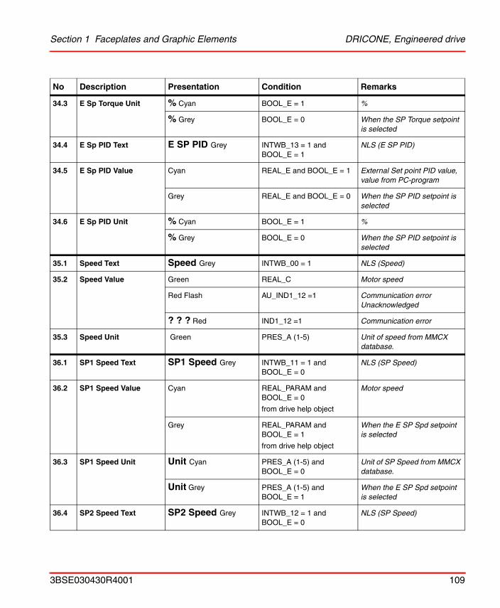
Section 1 Faceplates and Graphic Elements DRICONE, Engineered drive
34.3 E Sp Torque Unit % Cyan BOOL_E = 1 %
% Grey BOOL_E = 0 When the SP Torque setpoint is selected
34.4 E Sp PID Text E SP PID Grey INTWB_13 = 1 and BOOL_E = 1
NLS (E SP PID)
34.5 E Sp PID Value Cyan REAL_E and BOOL_E = 1 External Set point PID value, value from PC-program
Grey REAL_E and BOOL_E = 0 When the SP PID setpoint is selected
34.6 E Sp PID Unit % Cyan BOOL_E = 1 %
% Grey BOOL_E = 0 When the SP PID setpoint is selected
35.1 Speed Text Speed Grey INTWB_00 = 1 NLS (Speed)
35.2 Speed Value Green REAL_C Motor speed
Red Flash AU_IND1_12 =1 Communication error Unacknowledged
? ? ? Red IND1_12 =1 Communication error
35.3 Speed Unit Green PRES_A (1-5) Unit of speed from MMCX database.
36.1 SP1 Speed Text SP1 Speed Grey INTWB_11 = 1 and BOOL_E = 0
NLS (SP Speed)
36.2 SP1 Speed Value Cyan REAL_PARAM and BOOL_E = 0
from drive help object
Motor speed
Grey REAL_PARAM and BOOL_E = 1
from drive help object
When the E SP Spd setpoint is selected
36.3 SP1 Speed Unit Unit Cyan PRES_A (1-5) and BOOL_E = 0
Unit of SP Speed from MMCX database.
Unit Grey PRES_A (1-5) and BOOL_E = 1
When the E SP Spd setpoint is selected
36.4 SP2 Speed Text SP2 Speed Grey INTWB_12 = 1 and BOOL_E = 0
NLS (SP Speed)
No Description Presentation Condition Remarks
3BSE030430R4001 109
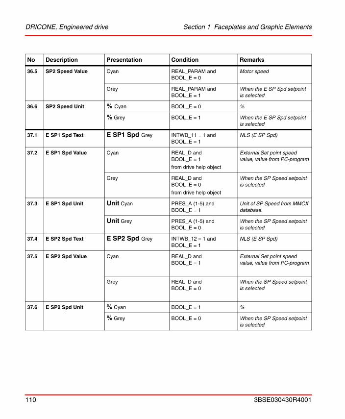
DRICONE, Engineered drive Section 1 Faceplates and Graphic Elements
36.5 SP2 Speed Value Cyan REAL_PARAM and BOOL_E = 0
Motor speed
Grey REAL_PARAM and BOOL_E = 1
When the E SP Spd setpoint is selected
36.6 SP2 Speed Unit % Cyan BOOL_E = 0 %
% Grey BOOL_E = 1 When the E SP Spd setpoint is selected
37.1 E SP1 Spd Text E SP1 Spd Grey INTWB_11 = 1 and BOOL_E = 1
NLS (E SP Spd)
37.2 E SP1 Spd Value Cyan REAL_D and BOOL_E = 1
from drive help object
External Set point speed value, value from PC-program
Grey REAL_D and BOOL_E = 0
from drive help object
When the SP Speed setpoint is selected
37.3 E SP1 Spd Unit Unit Cyan PRES_A (1-5) and BOOL_E = 1
Unit of SP Speed from MMCX database.
Unit Grey PRES_A (1-5) and BOOL_E = 0
When the SP Speed setpoint is selected
37.4 E SP2 Spd Text E SP2 Spd Grey INTWB_12 = 1 and BOOL_E = 1
NLS (E SP Spd)
37.5 E SP2 Spd Value Cyan REAL_D and BOOL_E = 1
External Set point speed value, value from PC-program
Grey REAL_D and BOOL_E = 0
When the SP Speed setpoint is selected
37.6 E SP2 Spd Unit % Cyan BOOL_E = 1 %
% Grey BOOL_E = 0 When the SP Speed setpoint is selected
No Description Presentation Condition Remarks
110 3BSE030430R4001
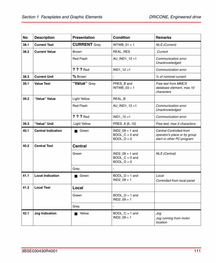
Section 1 Faceplates and Graphic Elements DRICONE, Engineered drive
38.1 Current Text CURRENT Grey INTWB_01 = 1 NLS (Current)
38.2 Current Value Brown REAL_RES Current
Red Flash AU_IND1_12 =1 Communication error Unacknowledged
? ? ? Red IND1_12 =1 Communication error
38.3 Current Unit % Brown - % of nominal current
39.1 Value Text “Value” Grey PRES_B and INTWB_03 = 1
Free text from MMCX database element, max 10 characters
39.2 “Value” Value Light Yellow REAL_B
Red Flash AU_IND1_12 =1 Communication error Unacknowledged
? ? ? Red IND1_12 =1 Communication error
39.3 “Value” Unit Light Yellow PRES_A [6..10] Free text, max 5 characters.
40.1 Central Indication Green IND2_09 = 1 andBOOL_C = 0 andBOOL_D = 0
Central Controlled from operator’s place or by group start or other PC-program
40.2 Central Text Central
Green IND2_09 = 1 andBOOL_C = 0 andBOOL_D = 0
NLS (Central)
Grey -
41.1 Local Indication Green BOOL_D = 1 andIND2_09 = 1
Local
Controlled from local panel
41.2 Local Text Local
Green BOOL_D = 1 andIND2_09 = 1
Grey -
42.1 Jog Indication Yellow BOOL_C = 1 and IND2_09 = 1
Jog
Jog running from motor location
No Description Presentation Condition Remarks
3BSE030430R4001 111
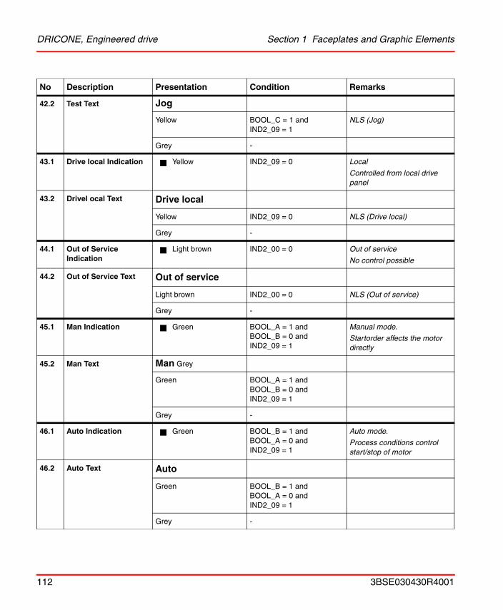
DRICONE, Engineered drive Section 1 Faceplates and Graphic Elements
42.2 Test Text Jog
Yellow BOOL_C = 1 and IND2_09 = 1
NLS (Jog)
Grey -
43.1 Drive local Indication Yellow IND2_09 = 0 Local
Controlled from local drive panel
43.2 Drivel ocal Text Drive local
Yellow IND2_09 = 0 NLS (Drive local)
Grey -
44.1 Out of Service Indication
Light brown IND2_00 = 0 Out of service
No control possible
44.2 Out of Service Text Out of service
Light brown IND2_00 = 0 NLS (Out of service)
Grey -
45.1 Man Indication Green BOOL_A = 1 andBOOL_B = 0 andIND2_09 = 1
Manual mode.
Startorder affects the motor directly
45.2 Man Text Man Grey
Green BOOL_A = 1 andBOOL_B = 0 andIND2_09 = 1
Grey -
46.1 Auto Indication Green BOOL_B = 1 andBOOL_A = 0 andIND2_09 = 1
Auto mode.
Process conditions control start/stop of motor
46.2 Auto Text Auto
Green BOOL_B = 1 andBOOL_A = 0 andIND2_09 = 1
Grey -
No Description Presentation Condition Remarks
112 3BSE030430R4001
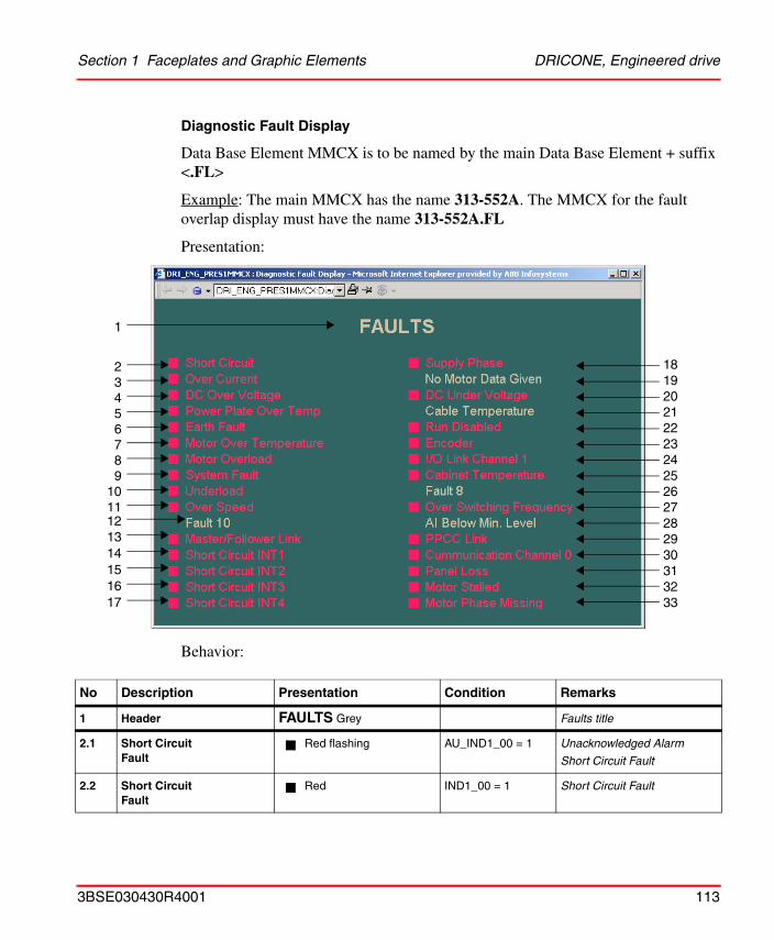
Section 1 Faceplates and Graphic Elements DRICONE, Engineered drive
Diagnostic Fault Display
Data Base Element MMCX is to be named by the main Data Base Element + suffix <.FL>
Example: The main MMCX has the name 313-552A. The MMCX for the fault overlap display must have the name 313-552A.FL
Presentation:
Behavior:
No Description Presentation Condition Remarks
1 Header FAULTS Grey Faults title
2.1 Short Circuit Fault
Red flashing AU_IND1_00 = 1 Unacknowledged Alarm
Short Circuit Fault
2.2 Short Circuit Fault
Red IND1_00 = 1 Short Circuit Fault
1
23456789
1011
1314151617
18192021222324252627282930313233
12
3BSE030430R4001 113
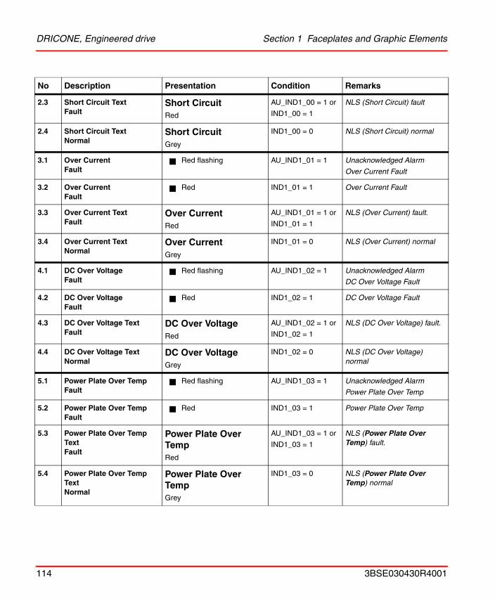
DRICONE, Engineered drive Section 1 Faceplates and Graphic Elements
2.3 Short Circuit Text Fault
Short CircuitRed
AU_IND1_00 = 1 or
IND1_00 = 1
NLS (Short Circuit) fault
2.4 Short Circuit TextNormal
Short CircuitGrey
IND1_00 = 0 NLS (Short Circuit) normal
3.1 Over CurrentFault
Red flashing AU_IND1_01 = 1 Unacknowledged Alarm
Over Current Fault
3.2 Over CurrentFault
Red IND1_01 = 1 Over Current Fault
3.3 Over Current Text Fault
Over CurrentRed
AU_IND1_01 = 1 or
IND1_01 = 1
NLS (Over Current) fault.
3.4 Over Current TextNormal
Over CurrentGrey
IND1_01 = 0 NLS (Over Current) normal
4.1 DC Over VoltageFault
Red flashing AU_IND1_02 = 1 Unacknowledged Alarm
DC Over Voltage Fault
4.2 DC Over VoltageFault
Red IND1_02 = 1 DC Over Voltage Fault
4.3 DC Over Voltage Text Fault
DC Over VoltageRed
AU_IND1_02 = 1 or
IND1_02 = 1
NLS (DC Over Voltage) fault.
4.4 DC Over Voltage TextNormal
DC Over VoltageGrey
IND1_02 = 0 NLS (DC Over Voltage) normal
5.1 Power Plate Over TempFault
Red flashing AU_IND1_03 = 1 Unacknowledged Alarm
Power Plate Over Temp
5.2 Power Plate Over TempFault
Red IND1_03 = 1 Power Plate Over Temp
5.3 Power Plate Over Temp Text Fault
Power Plate Over TempRed
AU_IND1_03 = 1 or
IND1_03 = 1
NLS (Power Plate Over Temp) fault.
5.4 Power Plate Over Temp TextNormal
Power Plate Over TempGrey
IND1_03 = 0 NLS (Power Plate Over Temp) normal
No Description Presentation Condition Remarks
114 3BSE030430R4001
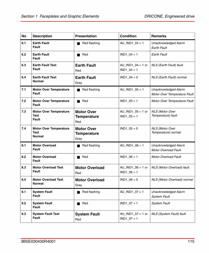
Section 1 Faceplates and Graphic Elements DRICONE, Engineered drive
6.1 Earth FaultFault
Red flashing AU_IND1_04 = 1 Unacknowledged Alarm
Earth Fault
6.2 Earth FaultFault
Red IND1_04 = 1 Earth Fault
6.3 Earth Fault Text Fault
Earth FaultRed
AU_IND1_04 = 1 or
IND1_04 = 1
NLS (Earth Fault) fault.
6.4 Earth Fault TextNormal
Earth FaultGrey
IND1_04 = 0 NLS (Earth Fault) normal
7.1 Motor Over TemperatureFault
Red flashing AU_IND1_05 = 1 Unacknowledged Alarm
Motor Over Temperature Fault
7.2 Motor Over TemperatureFault
Red IND1_05 = 1 Motor Over Temperature Fault
7.3 Motor Over Temperature Text Fault
Motor Over TemperatureRed
AU_IND1_05 = 1 or
IND1_05 = 1
NLS (Motor Over Temperature) fault.
7.4 Motor Over Temperature TextNormal
Motor Over TemperatureGrey
IND1_05 = 0 NLS (Motor Over Temperature) normal
8.1 Motor OverloadFault
Red flashing AU_IND1_06 = 1 Unacknowledged Alarm
Motor Overload Fault
8.2 Motor OverloadFault
Red IND1_06 = 1 Motor Overload Fault
8.3 Motor Overload Text Fault
Motor OverloadRed
AU_IND1_06 = 1 or
IND1_06 = 1
NLS (Motor Overload) fault.
8.4 Motor Overload TextNormal
Motor OverloadGrey
IND1_06 = 0 NLS (Motor Overload) normal
9.1 System FaultFault
Red flashing AU_IND1_07 = 1 Unacknowledged Alarm
System Fault
9.2 System FaultFault
Red IND1_07 = 1 System Fault
9.3 System Fault Text Fault
System FaultRed
AU_IND1_07 = 1 or
IND1_07 = 1
NLS (System Fault) fault.
No Description Presentation Condition Remarks
3BSE030430R4001 115
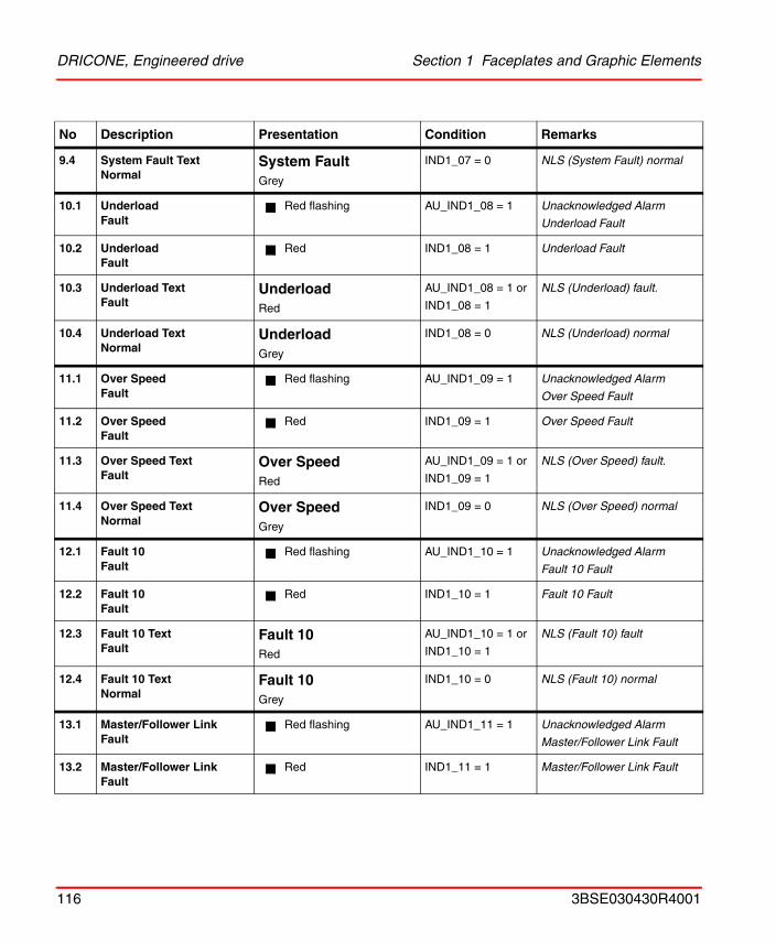
DRICONE, Engineered drive Section 1 Faceplates and Graphic Elements
9.4 System Fault TextNormal
System FaultGrey
IND1_07 = 0 NLS (System Fault) normal
10.1 UnderloadFault
Red flashing AU_IND1_08 = 1 Unacknowledged Alarm
Underload Fault
10.2 UnderloadFault
Red IND1_08 = 1 Underload Fault
10.3 Underload Text Fault
UnderloadRed
AU_IND1_08 = 1 or
IND1_08 = 1
NLS (Underload) fault.
10.4 Underload TextNormal
UnderloadGrey
IND1_08 = 0 NLS (Underload) normal
11.1 Over SpeedFault
Red flashing AU_IND1_09 = 1 Unacknowledged Alarm
Over Speed Fault
11.2 Over SpeedFault
Red IND1_09 = 1 Over Speed Fault
11.3 Over Speed Text Fault
Over SpeedRed
AU_IND1_09 = 1 or
IND1_09 = 1
NLS (Over Speed) fault.
11.4 Over Speed TextNormal
Over SpeedGrey
IND1_09 = 0 NLS (Over Speed) normal
12.1 Fault 10Fault
Red flashing AU_IND1_10 = 1 Unacknowledged Alarm
Fault 10 Fault
12.2 Fault 10Fault
Red IND1_10 = 1 Fault 10 Fault
12.3 Fault 10 TextFault
Fault 10Red
AU_IND1_10 = 1 or
IND1_10 = 1
NLS (Fault 10) fault
12.4 Fault 10 TextNormal
Fault 10Grey
IND1_10 = 0 NLS (Fault 10) normal
13.1 Master/Follower LinkFault
Red flashing AU_IND1_11 = 1 Unacknowledged Alarm
Master/Follower Link Fault
13.2 Master/Follower LinkFault
Red IND1_11 = 1 Master/Follower Link Fault
No Description Presentation Condition Remarks
116 3BSE030430R4001
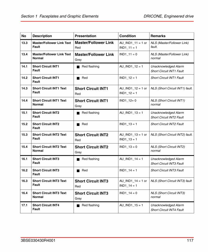
Section 1 Faceplates and Graphic Elements DRICONE, Engineered drive
13.3 Master/Follower Link TextFault
Master/Follower LinkRed
AU_IND1_11 = 1 or
IND1_11 = 1
NLS (Master/Follower Link) fault.
13.4 Master/Follower Link TextNormal
Master/Follower LinkGrey
IND1_11 = 0 NLS (Master/Follower Link) normal
14.1 Short Circuit INT1Fault
Red flashing AU_IND1_12 = 1 Unacknowledged Alarm
Short Circuit INT1 Fault
14.2 Short Circuit INT1Fault
Red IND1_12 = 1 Short Circuit INT1 Fault
14.3 Short Circuit INT1 TextFault
Short Circuit INT1Red
AU_IND1_12 = 1 or
IND1_12 = 1
NLS (Short Circuit INT1) fault.
14.4 Short Circuit INT1 TextNormal
Short Circuit INT1Grey
IND1_12= 0 NLS (Short Circuit INT1) normal
15.1 Short Circuit INT2Fault
Red flashing AU_IND1_13 = 1 Unacknowledged Alarm
Short Circuit INT2 Fault
15.2 Short Circuit INT2Fault
Red IND1_13 = 1 Short Circuit INT2 Fault
15.3 Short Circuit INT2 Text Fault
Short Circuit INT2Red
AU_IND1_13 = 1 or
IND1_13 = 1
NLS (Short Circuit INT2) fault.
15.4 Short Circuit INT2 TextNormal
Short Circuit INT2Grey
IND1_13 = 0 NLS (Short Circuit INT2) normal
16.1 Short Circuit INT3Fault
Red flashing AU_IND1_14 = 1 Unacknowledged Alarm
Short Circuit INT3 Fault
16.2 Short Circuit INT3Fault
Red IND1_14 = 1 Short Circuit INT3 Fault
16.3 Short Circuit INT3 TextFault
Short Circuit INT3Red
AU_IND1_14 = 1 or
IND1_14 = 1
NLS (Short Circuit INT3) fault
16.4 Short Circuit INT3 TextNormal
Short Circuit INT3Grey
IND1_14 = 0 NLS (Short Circuit INT3) normal
17.1 Short Circuit INT4Fault
Red flashing AU_IND1_15 = 1 Unacknowledged Alarm
Short Circuit INT4 Fault
No Description Presentation Condition Remarks
3BSE030430R4001 117

DRICONE, Engineered drive Section 1 Faceplates and Graphic Elements
17.2 Short Circuit INT4Fault
Red IND1_15 = 1 Short Circuit INT4 Fault
17.3 Short Circuit INT4 Text Fault
Short Circuit INT4Red
AU_IND1_15 = 1 or
IND1_15 = 1
NLS (Short Circuit INT4) fault.
17.4 Short Circuit INT4 TextNormal
Short Circuit INT4Grey
IND1_15 = 0 NLS (Short Circuit INT4) normal
18.1 Supply PhaseFault
Red flashing AU_IND2_00 = 1 Unacknowledged Alarm
Supply Phase Fault
18.2 Supply PhaseFault
Red IND2_00 = 1 Supply Phase Fault
18.3 Supply Phase Text Fault
Supply PhaseRed
AU_IND2_00 = 1 or
IND2_00 = 1
NLS (Supply Phase) Fault.
18.4 Supply Phase TextNormal
Supply PhaseGrey
IND2_00 = 0 NLS (Supply Phase) normal
19.1 No Motor Data GivenFault
Red flashing AU_IND2_01 = 1 Unacknowledged Alarm
No Motor Data Given Fault
19.2 No Motor Data GivenFault
Red IND2_01 = 1 No Motor Data Given Fault
19.3 No Motor Data GivenText Fault
No Motor Data GivenRed
AU_IND2_01 = 1 or
IND2_01 = 1
NLS (No Motor Data Given) Fault
19.4 No Motor Data GivenText Normal
No Motor Data GivenGrey
IND2_01 = 0 NLS (No Motor Data Given) normal
20.1 DC Under VoltageFault
Red flashing AU_IND2_02 = 1 Unacknowledged Alarm
DC Under Voltage Fault
20.2 DC Under VoltageFault
Red IND2_02 = 1 DC Under Voltage Fault
20.3 DC Under Voltage TextFault
DC Under VoltageRed
AU_IND2_02 = 1 or
IND2_02 = 1
NLS (DC Under Voltage) Fault.
20.4 DC Under Voltage TextNormal
DC Under VoltageGrey
IND2_02 = 0 NLS (DC Under Voltage) normal
No Description Presentation Condition Remarks
118 3BSE030430R4001
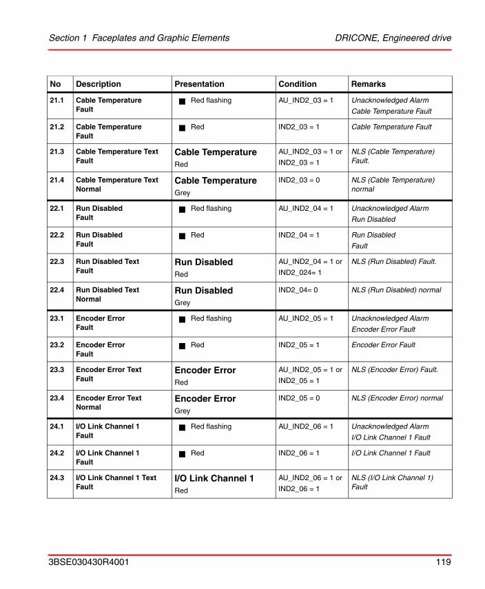
Section 1 Faceplates and Graphic Elements DRICONE, Engineered drive
21.1 Cable TemperatureFault
Red flashing AU_IND2_03 = 1 Unacknowledged Alarm
Cable Temperature Fault
21.2 Cable TemperatureFault
Red IND2_03 = 1 Cable Temperature Fault
21.3 Cable Temperature Text Fault
Cable TemperatureRed
AU_IND2_03 = 1 or
IND2_03 = 1
NLS (Cable Temperature) Fault.
21.4 Cable Temperature TextNormal
Cable TemperatureGrey
IND2_03 = 0 NLS (Cable Temperature) normal
22.1 Run DisabledFault
Red flashing AU_IND2_04 = 1 Unacknowledged Alarm
Run Disabled
22.2 Run DisabledFault
Red IND2_04 = 1 Run Disabled
Fault
22.3 Run Disabled Text Fault
Run DisabledRed
AU_IND2_04 = 1 or
IND2_024= 1
NLS (Run Disabled) Fault.
22.4 Run Disabled TextNormal
Run DisabledGrey
IND2_04= 0 NLS (Run Disabled) normal
23.1 Encoder ErrorFault
Red flashing AU_IND2_05 = 1 Unacknowledged Alarm
Encoder Error Fault
23.2 Encoder ErrorFault
Red IND2_05 = 1 Encoder Error Fault
23.3 Encoder Error Text Fault
Encoder ErrorRed
AU_IND2_05 = 1 or
IND2_05 = 1
NLS (Encoder Error) Fault.
23.4 Encoder Error TextNormal
Encoder ErrorGrey
IND2_05 = 0 NLS (Encoder Error) normal
24.1 I/O Link Channel 1Fault
Red flashing AU_IND2_06 = 1 Unacknowledged Alarm
I/O Link Channel 1 Fault
24.2 I/O Link Channel 1Fault
Red IND2_06 = 1 I/O Link Channel 1 Fault
24.3 I/O Link Channel 1 TextFault
I/O Link Channel 1Red
AU_IND2_06 = 1 or
IND2_06 = 1
NLS (I/O Link Channel 1) Fault
No Description Presentation Condition Remarks
3BSE030430R4001 119
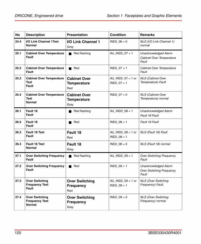
DRICONE, Engineered drive Section 1 Faceplates and Graphic Elements
24.4 I/O Link Channel 1TextNormal
I/O Link Channel 1Grey
IND2_06 = 0 NLS (I/O Link Channel 1) normal
25.1 Cabinet Over TemperatureFault
Red flashing AU_IND2_07 = 1 Unacknowledged Alarm
Cabinet Over Temperature Fault
25.2 Cabinet Over TemperatureFault
Red IND2_07 = 1 Cabinet Over Temperature Fault
25.3 Cabinet Over Temperature Text Fault
Cabinet Over TemperatureRed
AU_IND2_07 = 1 or
IND2_07 = 1
NLS (Cabinet Over Temperature) Fault
25.4 Cabinet Over Temperature Text Normal
Cabinet Over TemperatureGrey
IND2_07 = 0 NLS (Cabinet Over Temperature) normal
26.1 Fault 18Fault
Red flashing AU_IND2_08 = 1 Unacknowledged Alarm
Fault 18 Fault
26.2 Fault 18Fault
Red IND2_08 = 1 Fault 18 Fault
26.3 Fault 18 TextFault
Fault 18Red
AU_IND2_08 = 1 or
IND2_08 = 1
NLS (Fault 18) Fault
26.4 Fault 18 TextNormal
Fault 18Grey
IND2_08 = 0 NLS (Fault 18) normal
27.1 Over Switching FrequencyFault
Red flashing AU_IND2_09 = 1 Over Switching Frequency Fault
27.2 Over Switching FrequencyFault
Red IND2_09 = 1 Unacknowledged Alarm
Over Switching Frequency Fault
27.3 Over Switching Frequency Text Fault
Over Switching FrequencyRed
AU_IND2_09 = 1 or
IND2_09 = 1
NLS (Over Switching Frequency) Fault.
27.4 Over Switching Frequency TextNormal
Over Switching FrequencyGrey
IND2_09 = 0 NLS (Over Switching Frequency) normal
No Description Presentation Condition Remarks
120 3BSE030430R4001
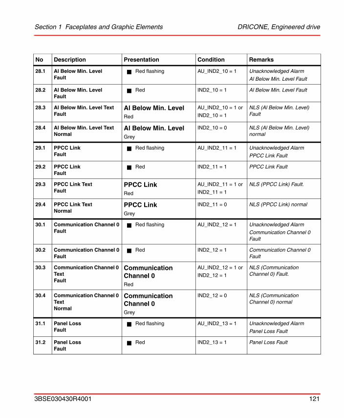
Section 1 Faceplates and Graphic Elements DRICONE, Engineered drive
28.1 Al Below Min. LevelFault
Red flashing AU_IND2_10 = 1 Unacknowledged Alarm
Al Below Min. Level Fault
28.2 Al Below Min. LevelFault
Red IND2_10 = 1 Al Below Min. Level Fault
28.3 Al Below Min. Level TextFault
Al Below Min. LevelRed
AU_IND2_10 = 1 or
IND2_10 = 1
NLS (Al Below Min. Level) Fault
28.4 Al Below Min. Level TextNormal
Al Below Min. LevelGrey
IND2_10 = 0 NLS (Al Below Min. Level) normal
29.1 PPCC LinkFault
Red flashing AU_IND2_11 = 1 Unacknowledged Alarm
PPCC Link Fault
29.2 PPCC LinkFault
Red IND2_11 = 1 PPCC Link Fault
29.3 PPCC Link TextFault
PPCC LinkRed
AU_IND2_11 = 1 or
IND2_11 = 1
NLS (PPCC Link) Fault.
29.4 PPCC Link TextNormal
PPCC LinkGrey
IND2_11 = 0 NLS (PPCC Link) normal
30.1 Communication Channel 0Fault
Red flashing AU_IND2_12 = 1 Unacknowledged Alarm
Communication Channel 0 Fault
30.2 Communication Channel 0Fault
Red IND2_12 = 1 Communication Channel 0 Fault
30.3 Communication Channel 0 Text Fault
Communication Channel 0Red
AU_IND2_12 = 1 or
IND2_12 = 1
NLS (Communication Channel 0) Fault.
30.4 Communication Channel 0 TextNormal
Communication Channel 0Grey
IND2_12 = 0 NLS (Communication Channel 0) normal
31.1 Panel LossFault
Red flashing AU_IND2_13 = 1 Unacknowledged Alarm
Panel Loss Fault
31.2 Panel LossFault
Red IND2_13 = 1 Panel Loss Fault
No Description Presentation Condition Remarks
3BSE030430R4001 121
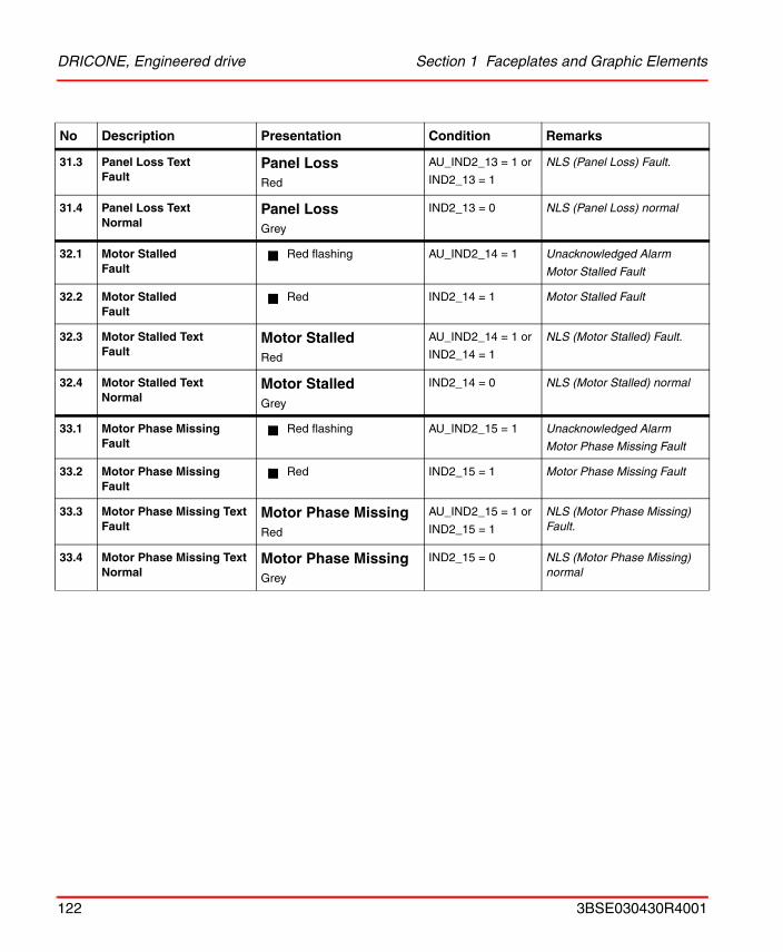
DRICONE, Engineered drive Section 1 Faceplates and Graphic Elements
31.3 Panel Loss Text Fault
Panel LossRed
AU_IND2_13 = 1 or
IND2_13 = 1
NLS (Panel Loss) Fault.
31.4 Panel Loss TextNormal
Panel LossGrey
IND2_13 = 0 NLS (Panel Loss) normal
32.1 Motor StalledFault
Red flashing AU_IND2_14 = 1 Unacknowledged Alarm
Motor Stalled Fault
32.2 Motor StalledFault
Red IND2_14 = 1 Motor Stalled Fault
32.3 Motor Stalled TextFault
Motor StalledRed
AU_IND2_14 = 1 or
IND2_14 = 1
NLS (Motor Stalled) Fault.
32.4 Motor Stalled TextNormal
Motor StalledGrey
IND2_14 = 0 NLS (Motor Stalled) normal
33.1 Motor Phase MissingFault
Red flashing AU_IND2_15 = 1 Unacknowledged Alarm
Motor Phase Missing Fault
33.2 Motor Phase MissingFault
Red IND2_15 = 1 Motor Phase Missing Fault
33.3 Motor Phase Missing Text Fault
Motor Phase MissingRed
AU_IND2_15 = 1 or
IND2_15 = 1
NLS (Motor Phase Missing) Fault.
33.4 Motor Phase Missing TextNormal
Motor Phase MissingGrey
IND2_15 = 0 NLS (Motor Phase Missing) normal
No Description Presentation Condition Remarks
122 3BSE030430R4001
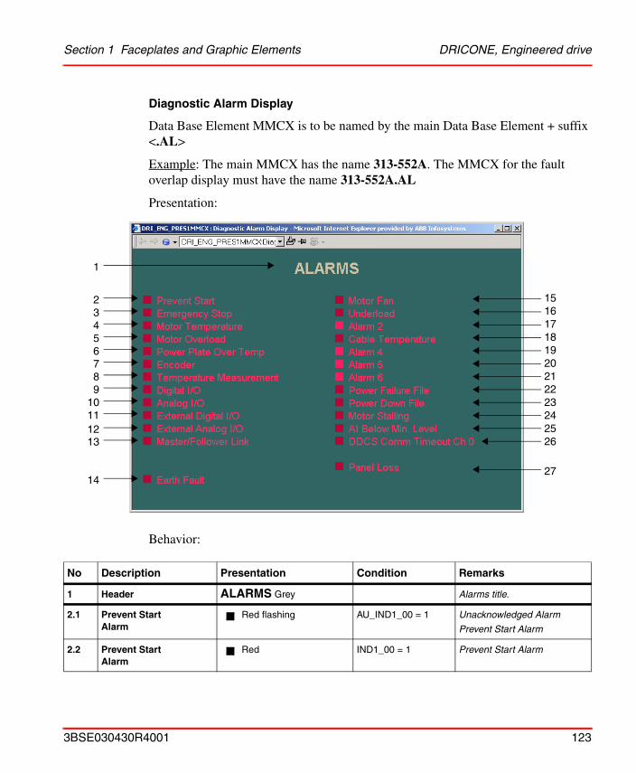
Section 1 Faceplates and Graphic Elements DRICONE, Engineered drive
Diagnostic Alarm Display
Data Base Element MMCX is to be named by the main Data Base Element + suffix <.AL>
Example: The main MMCX has the name 313-552A. The MMCX for the fault overlap display must have the name 313-552A.AL
Presentation:
Behavior:
No Description Presentation Condition Remarks
1 Header ALARMS Grey Alarms title.
2.1 Prevent Start Alarm
Red flashing AU_IND1_00 = 1 Unacknowledged Alarm
Prevent Start Alarm
2.2 Prevent Start Alarm
Red IND1_00 = 1 Prevent Start Alarm
1
23456789
10111213
14
151617181920212223242526
27
3BSE030430R4001 123
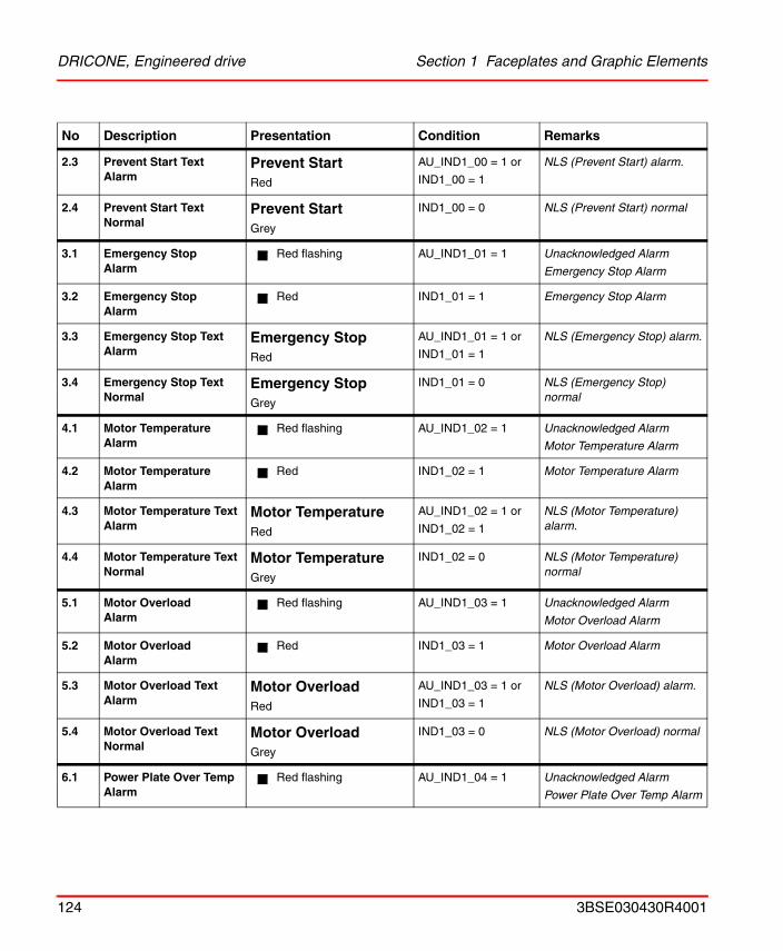
DRICONE, Engineered drive Section 1 Faceplates and Graphic Elements
2.3 Prevent Start Text Alarm
Prevent Start Red
AU_IND1_00 = 1 or
IND1_00 = 1
NLS (Prevent Start) alarm.
2.4 Prevent Start TextNormal
Prevent Start Grey
IND1_00 = 0 NLS (Prevent Start) normal
3.1 Emergency StopAlarm
Red flashing AU_IND1_01 = 1 Unacknowledged Alarm
Emergency Stop Alarm
3.2 Emergency StopAlarm
Red IND1_01 = 1 Emergency Stop Alarm
3.3 Emergency Stop Text Alarm
Emergency StopRed
AU_IND1_01 = 1 or
IND1_01 = 1
NLS (Emergency Stop) alarm.
3.4 Emergency Stop TextNormal
Emergency StopGrey
IND1_01 = 0 NLS (Emergency Stop) normal
4.1 Motor TemperatureAlarm
Red flashing AU_IND1_02 = 1 Unacknowledged Alarm
Motor Temperature Alarm
4.2 Motor TemperatureAlarm
Red IND1_02 = 1 Motor Temperature Alarm
4.3 Motor Temperature Text Alarm
Motor TemperatureRed
AU_IND1_02 = 1 or
IND1_02 = 1
NLS (Motor Temperature) alarm.
4.4 Motor Temperature TextNormal
Motor TemperatureGrey
IND1_02 = 0 NLS (Motor Temperature) normal
5.1 Motor OverloadAlarm
Red flashing AU_IND1_03 = 1 Unacknowledged Alarm
Motor Overload Alarm
5.2 Motor OverloadAlarm
Red IND1_03 = 1 Motor Overload Alarm
5.3 Motor Overload Text Alarm
Motor OverloadRed
AU_IND1_03 = 1 or
IND1_03 = 1
NLS (Motor Overload) alarm.
5.4 Motor Overload TextNormal
Motor OverloadGrey
IND1_03 = 0 NLS (Motor Overload) normal
6.1 Power Plate Over TempAlarm
Red flashing AU_IND1_04 = 1 Unacknowledged Alarm
Power Plate Over Temp Alarm
No Description Presentation Condition Remarks
124 3BSE030430R4001
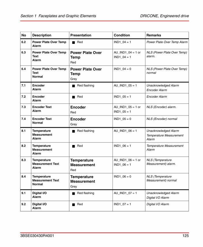
Section 1 Faceplates and Graphic Elements DRICONE, Engineered drive
6.2 Power Plate Over TempAlarm
Red IND1_04 = 1 Power Plate Over Temp Alarm
6.3 Power Plate Over Temp Text Alarm
Power Plate Over TempRed
AU_IND1_04 = 1 or
IND1_04 = 1
NLS (Power Plate Over Temp) alarm.
6.4 Power Plate Over Temp TextNormal
Power Plate Over TempGrey
IND1_04 = 0 NLS (Power Plate Over Temp) normal
7.1 EncoderAlarm
Red flashing AU_IND1_05 = 1 Unacknowledged Alarm
Encoder Alarm
7.2 EncoderAlarm
Red IND1_05 = 1 Encoder Alarm
7.3 Encoder Text Alarm
EncoderRed
AU_IND1_05 = 1 or
IND1_05 = 1
NLS (Encoder) alarm.
7.4 Encoder TextNormal
EncoderGrey
IND1_05 = 0 NLS (Encoder) normal
8.1 Temperature MeasurementAlarm
Red flashing AU_IND1_06 = 1 Unacknowledged Alarm
Temperature Measurement Alarm
8.2 Temperature MeasurementAlarm
Red IND1_06 = 1 Temperature Measurement Alarm
8.3 Temperature Measurement Text Alarm
Temperature MeasurementRed
AU_IND1_06 = 1 or
IND1_06 = 1
NLS (Temperature Measurement) alarm.
8.4 Temperature Measurement TextNormal
Temperature MeasurementGrey
IND1_06 = 0 NLS (Temperature Measurement) normal
9.1 Digital I/OAlarm
Red flashing AU_IND1_07 = 1 Unacknowledged Alarm
Digital I/O Alarm
9.2 Digital I/OAlarm
Red IND1_07 = 1 Digital I/O Alarm
No Description Presentation Condition Remarks
3BSE030430R4001 125
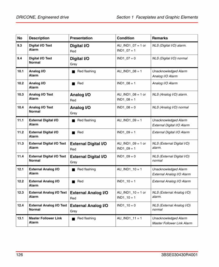
DRICONE, Engineered drive Section 1 Faceplates and Graphic Elements
9.3 Digital I/O Text Alarm
Digital I/ORed
AU_IND1_07 = 1 or
IND1_07 = 1
NLS (Digital I/O) alarm.
9.4 Digital I/O TextNormal
Digital I/OGrey
IND1_07 = 0 NLS (Digital I/O) normal
10.1 Analog I/OAlarm
Red flashing AU_IND1_08 = 1 Unacknowledged Alarm
Analog I/O Alarm
10.2 Analog I/OAlarm
Red IND1_08 = 1 Analog I/O Alarm
10.3 Analog I/O Text Alarm
Analog I/ORed
AU_IND1_08 = 1 or
IND1_08 = 1
NLS (Analog I/O) alarm.
10.4 Analog I/O TextNormal
Analog I/OGrey
IND1_08 = 0 NLS (Analog I/O) normal
11.1 External Digital I/OAlarm
Red flashing AU_IND1_09 = 1 Unacknowledged Alarm
External Digital I/O Alarm
11.2 External Digital I/OAlarm
Red IND1_09 = 1 External Digital I/O Alarm
11.3 External Digital I/O Text Alarm
External Digital I/ORed
AU_IND1_09 = 1 or
IND1_09 = 1
NLS (External Digital I/O) alarm.
11.4 External Digital I/O TextNormal
External Digital I/OGrey
IND1_09 = 0 NLS (External Digital I/O) normal
12.1 External Analog I/OAlarm
Red flashing AU_IND1_10 = 1 Unacknowledged Alarm
External Analog I/O Alarm
12.2 External Analog I/OAlarm
Red IND1_10 = 1 External Analog I/O Alarm
12.3 External Analog I/O Text Alarm
External Analog I/ORed
AU_IND1_10 = 1 or
IND1_10 = 1
NLS (External Analog I/O) alarm.
12.4 External Analog I/O TextNormal
External Analog I/OGrey
IND1_10 = 0 NLS (External Analog I/O) normal
13.1 Master Follower LinkAlarm
Red flashing AU_IND1_11 = 1 Unacknowledged Alarm
Master Follower Link Alarm
No Description Presentation Condition Remarks
126 3BSE030430R4001
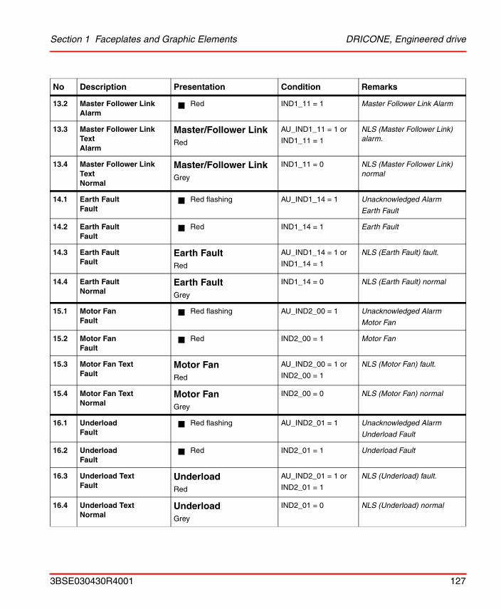
Section 1 Faceplates and Graphic Elements DRICONE, Engineered drive
13.2 Master Follower LinkAlarm
Red IND1_11 = 1 Master Follower Link Alarm
13.3 Master Follower Link Text Alarm
Master/Follower LinkRed
AU_IND1_11 = 1 or
IND1_11 = 1
NLS (Master Follower Link) alarm.
13.4 Master Follower Link TextNormal
Master/Follower LinkGrey
IND1_11 = 0 NLS (Master Follower Link) normal
14.1 Earth FaultFault
Red flashing AU_IND1_14 = 1 Unacknowledged Alarm
Earth Fault
14.2 Earth FaultFault
Red IND1_14 = 1 Earth Fault
14.3 Earth Fault Fault
Earth FaultRed
AU_IND1_14 = 1 or
IND1_14 = 1
NLS (Earth Fault) fault.
14.4 Earth Fault Normal
Earth FaultGrey
IND1_14 = 0 NLS (Earth Fault) normal
15.1 Motor FanFault
Red flashing AU_IND2_00 = 1 Unacknowledged Alarm
Motor Fan
15.2 Motor FanFault
Red IND2_00 = 1 Motor Fan
15.3 Motor Fan Text Fault
Motor FanRed
AU_IND2_00 = 1 or
IND2_00 = 1
NLS (Motor Fan) fault.
15.4 Motor Fan TextNormal
Motor FanGrey
IND2_00 = 0 NLS (Motor Fan) normal
16.1 UnderloadFault
Red flashing AU_IND2_01 = 1 Unacknowledged Alarm
Underload Fault
16.2 UnderloadFault
Red IND2_01 = 1 Underload Fault
16.3 Underload Text Fault
UnderloadRed
AU_IND2_01 = 1 or
IND2_01 = 1
NLS (Underload) fault.
16.4 Underload TextNormal
UnderloadGrey
IND2_01 = 0 NLS (Underload) normal
No Description Presentation Condition Remarks
3BSE030430R4001 127
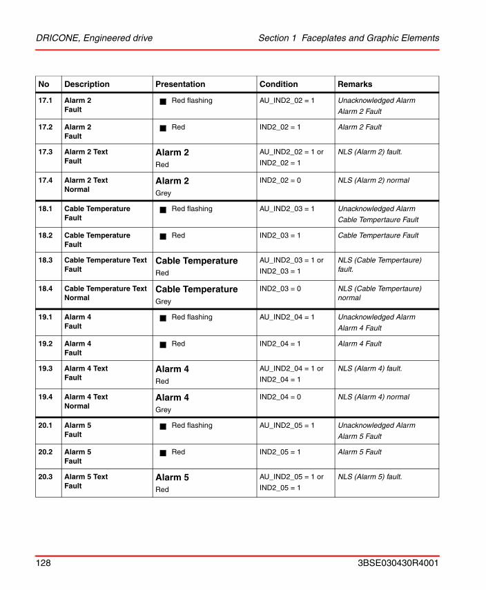
DRICONE, Engineered drive Section 1 Faceplates and Graphic Elements
17.1 Alarm 2Fault
Red flashing AU_IND2_02 = 1 Unacknowledged Alarm
Alarm 2 Fault
17.2 Alarm 2Fault
Red IND2_02 = 1 Alarm 2 Fault
17.3 Alarm 2 Text Fault
Alarm 2Red
AU_IND2_02 = 1 or
IND2_02 = 1
NLS (Alarm 2) fault.
17.4 Alarm 2 TextNormal
Alarm 2Grey
IND2_02 = 0 NLS (Alarm 2) normal
18.1 Cable TemperatureFault
Red flashing AU_IND2_03 = 1 Unacknowledged Alarm
Cable Tempertaure Fault
18.2 Cable TemperatureFault
Red IND2_03 = 1 Cable Tempertaure Fault
18.3 Cable Temperature Text Fault
Cable TemperatureRed
AU_IND2_03 = 1 or
IND2_03 = 1
NLS (Cable Tempertaure) fault.
18.4 Cable Temperature TextNormal
Cable TemperatureGrey
IND2_03 = 0 NLS (Cable Tempertaure) normal
19.1 Alarm 4Fault
Red flashing AU_IND2_04 = 1 Unacknowledged Alarm
Alarm 4 Fault
19.2 Alarm 4Fault
Red IND2_04 = 1 Alarm 4 Fault
19.3 Alarm 4 Text Fault
Alarm 4Red
AU_IND2_04 = 1 or
IND2_04 = 1
NLS (Alarm 4) fault.
19.4 Alarm 4 TextNormal
Alarm 4Grey
IND2_04 = 0 NLS (Alarm 4) normal
20.1 Alarm 5Fault
Red flashing AU_IND2_05 = 1 Unacknowledged Alarm
Alarm 5 Fault
20.2 Alarm 5Fault
Red IND2_05 = 1 Alarm 5 Fault
20.3 Alarm 5 Text Fault
Alarm 5Red
AU_IND2_05 = 1 or
IND2_05 = 1
NLS (Alarm 5) fault.
No Description Presentation Condition Remarks
128 3BSE030430R4001
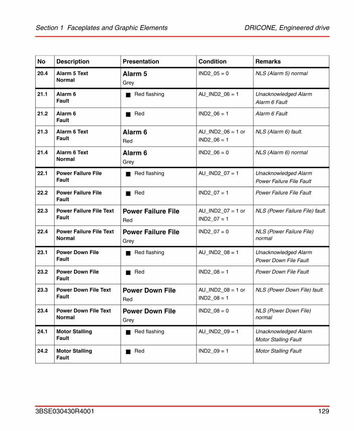
Section 1 Faceplates and Graphic Elements DRICONE, Engineered drive
20.4 Alarm 5 TextNormal
Alarm 5Grey
IND2_05 = 0 NLS (Alarm 5) normal
21.1 Alarm 6Fault
Red flashing AU_IND2_06 = 1 Unacknowledged Alarm
Alarm 6 Fault
21.2 Alarm 6Fault
Red IND2_06 = 1 Alarm 6 Fault
21.3 Alarm 6 Text Fault
Alarm 6Red
AU_IND2_06 = 1 or
IND2_06 = 1
NLS (Alarm 6) fault.
21.4 Alarm 6 TextNormal
Alarm 6Grey
IND2_06 = 0 NLS (Alarm 6) normal
22.1 Power Failure FileFault
Red flashing AU_IND2_07 = 1 Unacknowledged Alarm
Power Failure File Fault
22.2 Power Failure FileFault
Red IND2_07 = 1 Power Failure File Fault
22.3 Power Failure File Text Fault
Power Failure FileRed
AU_IND2_07 = 1 or
IND2_07 = 1
NLS (Power Failure File) fault.
22.4 Power Failure File TextNormal
Power Failure FileGrey
IND2_07 = 0 NLS (Power Failure File) normal
23.1 Power Down FileFault
Red flashing AU_IND2_08 = 1 Unacknowledged Alarm
Power Down File Fault
23.2 Power Down FileFault
Red IND2_08 = 1 Power Down File Fault
23.3 Power Down File Text Fault
Power Down FileRed
AU_IND2_08 = 1 or
IND2_08 = 1
NLS (Power Down File) fault.
23.4 Power Down File TextNormal
Power Down FileGrey
IND2_08 = 0 NLS (Power Down File) normal
24.1 Motor StallingFault
Red flashing AU_IND2_09 = 1 Unacknowledged Alarm
Motor Stalling Fault
24.2 Motor StallingFault
Red IND2_09 = 1 Motor Stalling Fault
No Description Presentation Condition Remarks
3BSE030430R4001 129
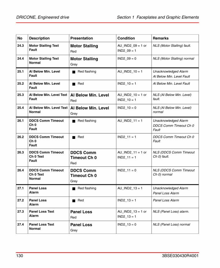
DRICONE, Engineered drive Section 1 Faceplates and Graphic Elements
24.3 Motor Stalling Text Fault
Motor StallingRed
AU_IND2_09 = 1 or
IND2_09 = 1
NLS (Motor Stalling) fault.
24.4 Motor Stalling TextNormal
Motor StallingGrey
IND2_09 = 0 NLS (Motor Stalling) normal
25.1 Al Below Min. LevelFault
Red flashing AU_IND2_10 = 1 Unacknowledged Alarm
Al Below Min. Level Fault
25.2 Al Below Min. LevelFault
Red IND2_10 = 1 Al Below Min. Level Fault
25.3 Al Below Min. Level Text Fault
Al Below Min. LevelRed
AU_IND2_10 = 1 or
IND2_10 = 1
NLS (Al Below Min. Level) fault.
25.4 Al Below Min. Level TextNormal
Al Below Min. LevelGrey
IND2_10 = 0 NLS (Al Below Min. Level) normal
26.1 DDCS Comm Timeout Ch 0Fault
Red flashing AU_IND2_11 = 1 Unacknowledged Alarm
DDCS Comm Timeout Ch 0 Fault
26.2 DDCS Comm Timeout Ch 0Fault
Red IND2_11 = 1 DDCS Comm Timeout Ch 0 Fault
26.3 DDCS Comm Timeout Ch 0 Text Fault
DDCS Comm Timeout Ch 0Red
AU_IND2_11 = 1 or
IND2_11 = 1
NLS (DDCS Comm Timeout Ch 0) fault.
26.4 DDCS Comm Timeout Ch 0 TextNormal
DDCS Comm Timeout Ch 0Grey
IND2_11 = 0 NLS (DDCS Comm Timeout Ch 0) normal
27.1 Panel Loss Alarm
Red flashing AU_IND2_13 = 1 Unacknowledged Alarm
Panel Loss Alarm
27.2 Panel Loss Alarm
Red IND2_13 = 1 Panel Loss Alarm
27.3 Panel Loss Text Alarm
Panel Loss Red
AU_IND2_13 = 1 or
IND2_13 = 1
NLS (Panel Loss) alarm.
27.4 Panel Loss TextNormal
Panel Loss Grey
IND2_13 = 0 NLS (Panel Loss) normal
No Description Presentation Condition Remarks
130 3BSE030430R4001
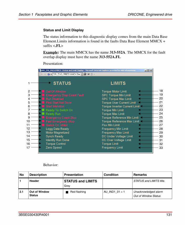
Section 1 Faceplates and Graphic Elements DRICONE, Engineered drive
Status and Limit Display
The status information to this diagnostic display comes from the main Data Base Element.Limits information is found in the faults Data Base Element MMCX + suffix <.FL>
Example: The main MMCX has the name 313-552A. The MMCX for the fault overlap display must have the name 313-552A.FL
Presentation:
Behavior:
No Description Presentation Condition Remarks
1 Header STATUS and LIMITSGrey
STATUS and LIMITS title.
2.1 Out of WindowStatus
Red flashing AU_IND1_01 = 1 Unacknowledged alarm
Out of Window Status
1
23456789
1011
1314151617
18192021222324252627282930313233
12
3BSE030430R4001 131
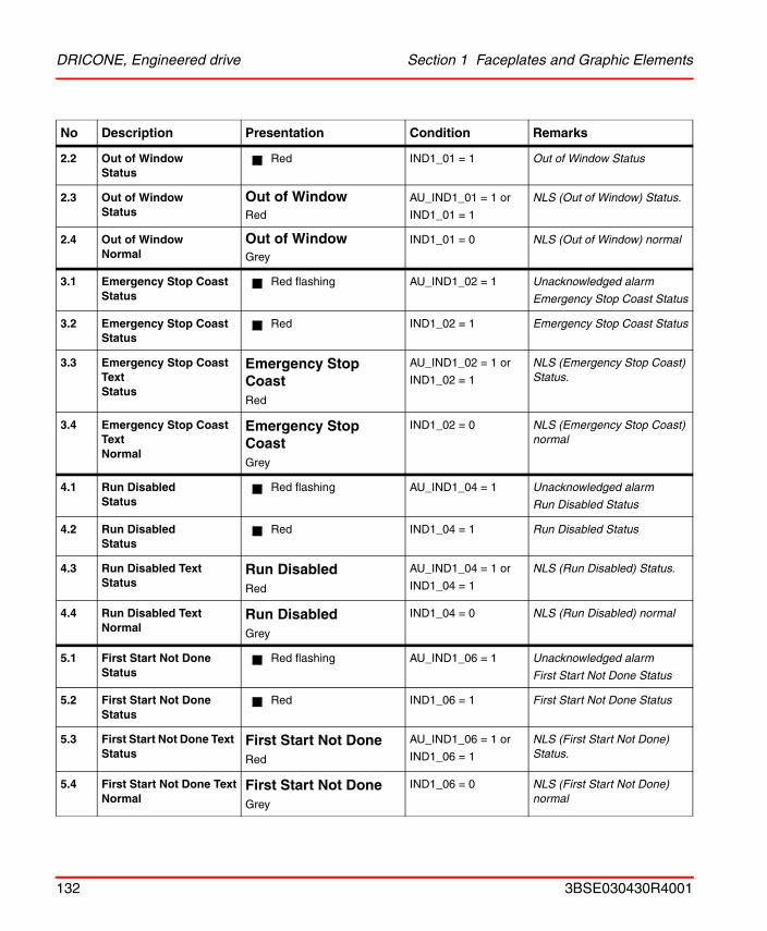
DRICONE, Engineered drive Section 1 Faceplates and Graphic Elements
2.2 Out of WindowStatus
Red IND1_01 = 1 Out of Window Status
2.3 Out of WindowStatus
Out of Window
Red
AU_IND1_01 = 1 or
IND1_01 = 1
NLS (Out of Window) Status.
2.4 Out of WindowNormal
Out of Window
Grey
IND1_01 = 0 NLS (Out of Window) normal
3.1 Emergency Stop CoastStatus
Red flashing AU_IND1_02 = 1 Unacknowledged alarm
Emergency Stop Coast Status
3.2 Emergency Stop CoastStatus
Red IND1_02 = 1 Emergency Stop Coast Status
3.3 Emergency Stop Coast Text Status
Emergency Stop CoastRed
AU_IND1_02 = 1 or
IND1_02 = 1
NLS (Emergency Stop Coast) Status.
3.4 Emergency Stop Coast TextNormal
Emergency Stop CoastGrey
IND1_02 = 0 NLS (Emergency Stop Coast) normal
4.1 Run DisabledStatus
Red flashing AU_IND1_04 = 1 Unacknowledged alarm
Run Disabled Status
4.2 Run DisabledStatus
Red IND1_04 = 1 Run Disabled Status
4.3 Run Disabled Text Status
Run DisabledRed
AU_IND1_04 = 1 or
IND1_04 = 1
NLS (Run Disabled) Status.
4.4 Run Disabled TextNormal
Run DisabledGrey
IND1_04 = 0 NLS (Run Disabled) normal
5.1 First Start Not DoneStatus
Red flashing AU_IND1_06 = 1 Unacknowledged alarm
First Start Not Done Status
5.2 First Start Not DoneStatus
Red IND1_06 = 1 First Start Not Done Status
5.3 First Start Not Done Text Status
First Start Not DoneRed
AU_IND1_06 = 1 or
IND1_06 = 1
NLS (First Start Not Done) Status.
5.4 First Start Not Done TextNormal
First Start Not DoneGrey
IND1_06 = 0 NLS (First Start Not Done) normal
No Description Presentation Condition Remarks
132 3BSE030430R4001
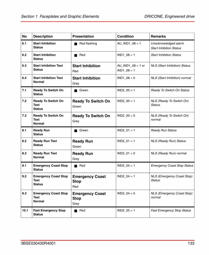
Section 1 Faceplates and Graphic Elements DRICONE, Engineered drive
6.1 Start InhibitionStatus
Red flashing AU_IND1_08 = 1 Unacknowledged alarm
Start Inhibition Status
6.2 Start InhibitionStatus
Red IND1_08 = 1 Start Inhibition Status
6.3 Start Inhibition Text Status
Start InhibitionRed
AU_IND1_08 = 1 or
IND1_08 = 1
NLS (Start Inhibition) Status.
6.4 Start Inhibition TextNormal
Start InhibitionGrey
IND1_08 = 0 NLS (Start Inhibition) normal
7.1 Ready To Switch OnStatus
Green IND2_00 = 1 Ready To Switch On Status
7.2 Ready To Switch On Text Status
Ready To Switch OnGreen
IND2_00 = 1 NLS (Ready To Switch On) Status.
7.3 Ready To Switch On TextNormal
Ready To Switch OnGrey
IND2_00 = 0 NLS (Ready To Switch On) normal
8.1 Ready RunStatus
Green IND2_01 = 1 Ready Run Status
8.2 Ready Run Text Status
Ready RunGreen
IND2_01 = 1 NLS (Ready Run) Status.
8.3 Ready Run TextNormal
Ready RunGrey
IND2_01 = 0 NLS (Ready Run) normal
9.1 Emergency Coast StopStatus
Red IND2_04 = 1 Emergency Coast Stop Status
9.2 Emergency Coast Stop Text Status
Emergency Coast StopRed
IND2_04 = 1 NLS (Emergency Coast Stop) Status.
9.3 Emergency Coast Stop TextNormal
Emergency Coast StopGrey
IND2_04 = 0 NLS (Emergency Coast Stop) normal
10.1 Fast Emergency StopStatus
Red IND2_05 = 1 Fast Emergency Stop Status
No Description Presentation Condition Remarks
3BSE030430R4001 133
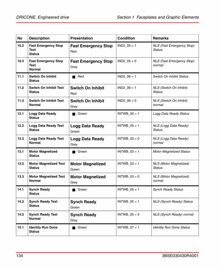
DRICONE, Engineered drive Section 1 Faceplates and Graphic Elements
10.2 Fast Emergency Stop Text Status
Fast Emergency StopRed
IND2_05 = 1 NLS (Fast Emergency Stop) Status.
10.3 Fast Emergency Stop TextNormal
Fast Emergency StopGrey
IND2_05 = 0 NLS (Fast Emergency Stop) normal
11.1 Switch On InhibitStatus
Red IND2_06 = 1 Switch On Inhibit Status
11.2 Switch On Inhibit Text Status
Switch On InhibitRed
IND2_06 = 1 NLS (Switch On Inhibit) Status.
11.3 Switch On Inhibit TextNormal
Switch On InhibitGrey
IND2_06 = 0 NLS (Switch On Inhibit) normal
12.1 Logg Data ReadyStatus
Green INTWB_00 = 1 Logg Data Ready Status
12.2 Logg Data Ready Text Status
Logg Data ReadyGreen
INTWB_00 = 1 NLS (Logg Data Ready) Status.
12.3 Logg Data Ready TextNormal
Logg Data ReadyGrey
INTWB_00 = 0 NLS (Logg Data Ready) normal
13.1 Motor MagnetizedStatus
Green INTWB_03 = 1 Motor Magnetized Status
13.2 Motor Magnetized Text Status
Motor MagnetizedGreen
INTWB_03 = 1 NLS (Motor Magnetized) Status.
13.3 Motor Magnetized TextNormal
Motor MagnetizedGrey
INTWB_03 = 0 NLS (Motor Magnetized) normal
14.1 Synch ReadyStatus
Green INTWB_05 = 1 Synch Ready Status
14.2 Synch Ready Text Status
Synch ReadyGreen
INTWB_05 = 1 NLS (Synch Ready) Status.
14.3 Synch Ready TextNormal
Synch ReadyGrey
INTWB_05 = 0 NLS (Synch Ready) normal
15.1 Identity Run DoneStatus
Green INTWB_07 = 1 Identity Run Done Status
No Description Presentation Condition Remarks
134 3BSE030430R4001
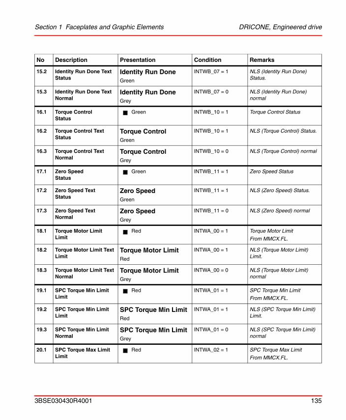
Section 1 Faceplates and Graphic Elements DRICONE, Engineered drive
15.2 Identity Run Done Text Status
Identity Run DoneGreen
INTWB_07 = 1 NLS (Identity Run Done) Status.
15.3 Identity Run Done TextNormal
Identity Run DoneGrey
INTWB_07 = 0 NLS (Identity Run Done) normal
16.1 Torque ControlStatus
Green INTWB_10 = 1 Torque Control Status
16.2 Torque Control Text Status
Torque ControlGreen
INTWB_10 = 1 NLS (Torque Control) Status.
16.3 Torque Control TextNormal
Torque ControlGrey
INTWB_10 = 0 NLS (Torque Control) normal
17.1 Zero SpeedStatus
Green INTWB_11 = 1 Zero Speed Status
17.2 Zero Speed Text Status
Zero SpeedGreen
INTWB_11 = 1 NLS (Zero Speed) Status.
17.3 Zero Speed TextNormal
Zero SpeedGrey
INTWB_11 = 0 NLS (Zero Speed) normal
18.1 Torque Motor LimitLimit
Red INTWA_00 = 1 Torque Motor Limit
From MMCX.FL.
18.2 Torque Motor Limit Text Limit
Torque Motor LimitRed
INTWA_00 = 1 NLS (Torque Motor Limit) Limit.
18.3 Torque Motor Limit TextNormal
Torque Motor LimitGrey
INTWA_00 = 0 NLS (Torque Motor Limit) normal
19.1 SPC Torque Min LimitLimit
Red INTWA_01 = 1 SPC Torque Min Limit
From MMCX.FL.
19.2 SPC Torque Min Limit Limit
SPC Torque Min LimitRed
INTWA_01 = 1 NLS (SPC Torque Min Limit) Limit.
19.3 SPC Torque Min Limit Normal
SPC Torque Min LimitGrey
INTWA_01 = 0 NLS (SPC Torque Min Limit) normal
20.1 SPC Torque Max LimitLimit
Red INTWA_02 = 1 SPC Torque Max Limit
From MMCX.FL.
No Description Presentation Condition Remarks
3BSE030430R4001 135
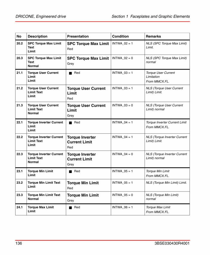
DRICONE, Engineered drive Section 1 Faceplates and Graphic Elements
20.2 SPC Torque Max Limit Text Limit
SPC Torque Max LimitRed
INTWA_02 = 1 NLS (SPC Torque Max Limit) Limit.
20.3 SPC Torque Max Limit TextNormal
SPC Torque Max LimitGrey
INTWA_02 = 0 NLS (SPC Torque Max Limit) normal
21.1 Torque User Current LimitLimit
Red INTWA_03 = 1 Torque User Current Limitation
From MMCX.FL.
21.2 Torque User Current Limit Text Limit
Torque User Current LimitRed
INTWA_03 = 1 NLS (Torque User Current Limit) Limit.
21.3 Torque User Current Limit TextNormal
Torque User Current LimitGrey
INTWA_03 = 0 NLS (Torque User Current Limit) normal
22.1 Torque Inverter Current LimitLimit
Red INTWA_04 = 1 Torque Inverter Current Limit
From MMCX.FL.
22.2 Torque Inverter Current Limit Text Limit
Torque Inverter Current LimitRed
INTWA_04 = 1 NLS (Torque Inverter Current Limit) Limit.
22.3 Torque Inverter Current Limit TextNormal
Torque Inverter Current LimitGrey
INTWA_04 = 0 NLS (Torque Inverter Current Limit) normal
23.1 Torque Min LimitLimit
Red INTWA_05 = 1 Torque Min Limit
From MMCX.FL.
23.2 Torque Min Limit Text Limit
Torque Min LimitRed
INTWA_05 = 1 NLS (Torque Min Limit) Limit.
23.3 Torque Min Limit TextNormal
Torque Min LimitGrey
INTWA_05 = 0 NLS (Torque Min Limit) normal
24.1 Torque Max LimitLimit
Red INTWA_06 = 1 Torque Max Limit
From MMCX.FL.
No Description Presentation Condition Remarks
136 3BSE030430R4001
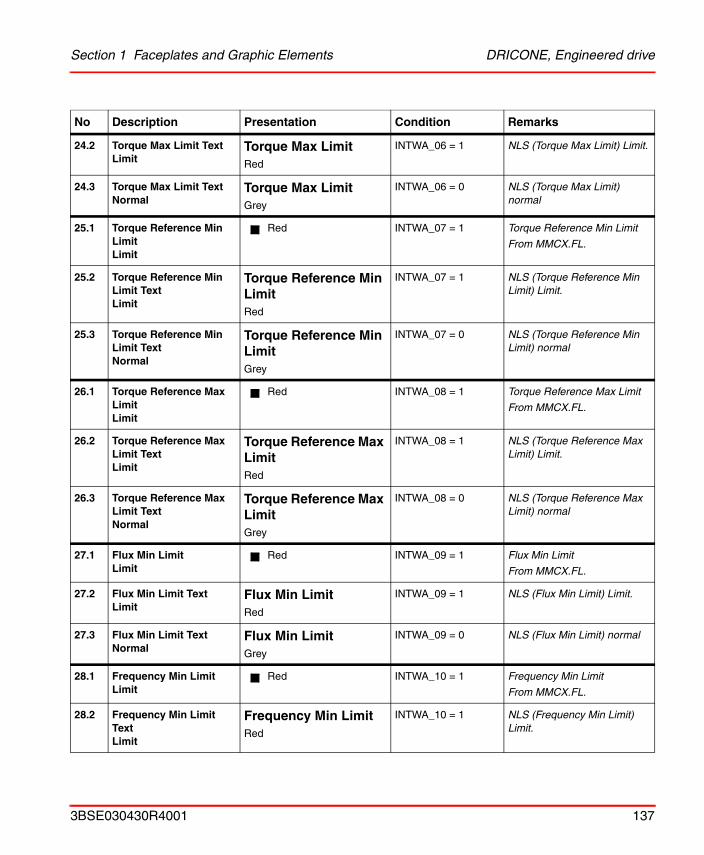
Section 1 Faceplates and Graphic Elements DRICONE, Engineered drive
24.2 Torque Max Limit Text Limit
Torque Max LimitRed
INTWA_06 = 1 NLS (Torque Max Limit) Limit.
24.3 Torque Max Limit TextNormal
Torque Max LimitGrey
INTWA_06 = 0 NLS (Torque Max Limit) normal
25.1 Torque Reference Min LimitLimit
Red INTWA_07 = 1 Torque Reference Min Limit
From MMCX.FL.
25.2 Torque Reference Min Limit Text Limit
Torque Reference Min LimitRed
INTWA_07 = 1 NLS (Torque Reference Min Limit) Limit.
25.3 Torque Reference Min Limit TextNormal
Torque Reference Min LimitGrey
INTWA_07 = 0 NLS (Torque Reference Min Limit) normal
26.1 Torque Reference Max LimitLimit
Red INTWA_08 = 1 Torque Reference Max Limit
From MMCX.FL.
26.2 Torque Reference Max Limit Text Limit
Torque Reference Max LimitRed
INTWA_08 = 1 NLS (Torque Reference Max Limit) Limit.
26.3 Torque Reference Max Limit TextNormal
Torque Reference Max LimitGrey
INTWA_08 = 0 NLS (Torque Reference Max Limit) normal
27.1 Flux Min LimitLimit
Red INTWA_09 = 1 Flux Min Limit
From MMCX.FL.
27.2 Flux Min Limit Text Limit
Flux Min LimitRed
INTWA_09 = 1 NLS (Flux Min Limit) Limit.
27.3 Flux Min Limit TextNormal
Flux Min LimitGrey
INTWA_09 = 0 NLS (Flux Min Limit) normal
28.1 Frequency Min LimitLimit
Red INTWA_10 = 1 Frequency Min Limit
From MMCX.FL.
28.2 Frequency Min Limit Text Limit
Frequency Min LimitRed
INTWA_10 = 1 NLS (Frequency Min Limit) Limit.
No Description Presentation Condition Remarks
3BSE030430R4001 137
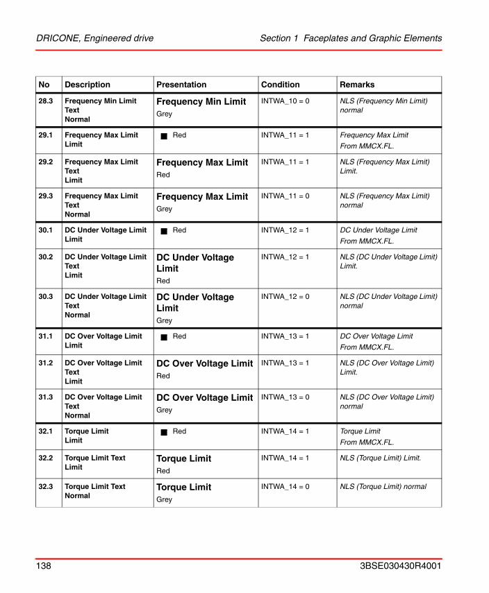
DRICONE, Engineered drive Section 1 Faceplates and Graphic Elements
28.3 Frequency Min Limit TextNormal
Frequency Min LimitGrey
INTWA_10 = 0 NLS (Frequency Min Limit) normal
29.1 Frequency Max LimitLimit
Red INTWA_11 = 1 Frequency Max Limit
From MMCX.FL.
29.2 Frequency Max Limit Text Limit
Frequency Max LimitRed
INTWA_11 = 1 NLS (Frequency Max Limit) Limit.
29.3 Frequency Max Limit TextNormal
Frequency Max LimitGrey
INTWA_11 = 0 NLS (Frequency Max Limit) normal
30.1 DC Under Voltage LimitLimit
Red INTWA_12 = 1 DC Under Voltage Limit
From MMCX.FL.
30.2 DC Under Voltage Limit Text Limit
DC Under Voltage LimitRed
INTWA_12 = 1 NLS (DC Under Voltage Limit) Limit.
30.3 DC Under Voltage Limit TextNormal
DC Under Voltage LimitGrey
INTWA_12 = 0 NLS (DC Under Voltage Limit) normal
31.1 DC Over Voltage LimitLimit
Red INTWA_13 = 1 DC Over Voltage Limit
From MMCX.FL.
31.2 DC Over Voltage Limit Text Limit
DC Over Voltage LimitRed
INTWA_13 = 1 NLS (DC Over Voltage Limit) Limit.
31.3 DC Over Voltage Limit TextNormal
DC Over Voltage LimitGrey
INTWA_13 = 0 NLS (DC Over Voltage Limit) normal
32.1 Torque LimitLimit
Red INTWA_14 = 1 Torque Limit
From MMCX.FL.
32.2 Torque Limit Text Limit
Torque LimitRed
INTWA_14 = 1 NLS (Torque Limit) Limit.
32.3 Torque Limit TextNormal
Torque LimitGrey
INTWA_14 = 0 NLS (Torque Limit) normal
No Description Presentation Condition Remarks
138 3BSE030430R4001
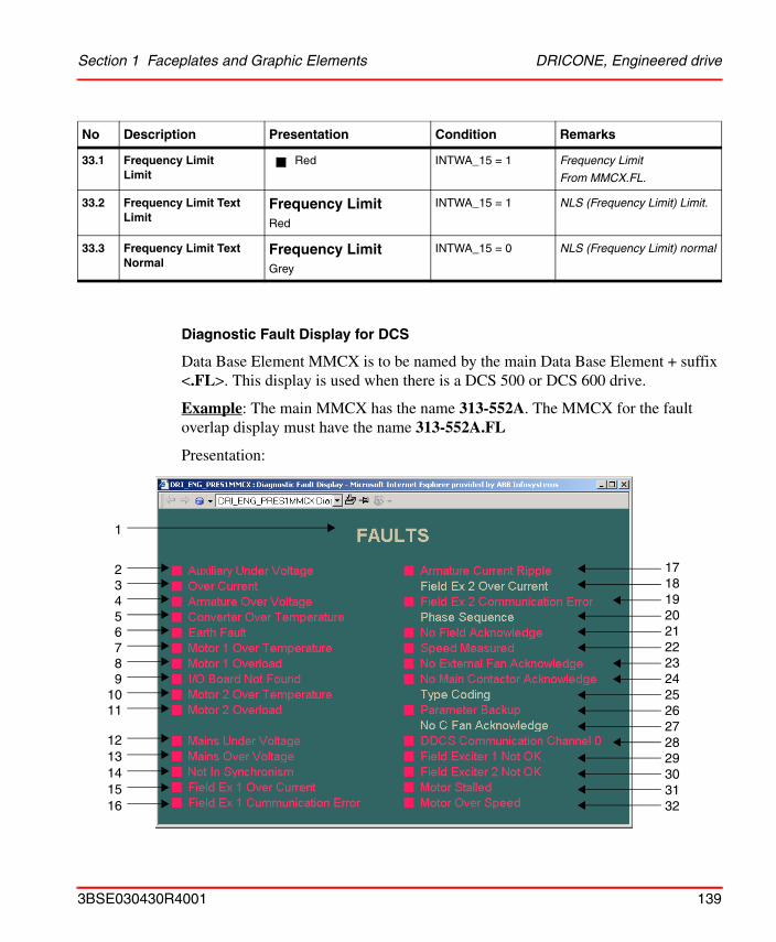
Section 1 Faceplates and Graphic Elements DRICONE, Engineered drive
Diagnostic Fault Display for DCS
Data Base Element MMCX is to be named by the main Data Base Element + suffix <.FL>. This display is used when there is a DCS 500 or DCS 600 drive.
Example: The main MMCX has the name 313-552A. The MMCX for the fault overlap display must have the name 313-552A.FL
Presentation:
33.1 Frequency Limit Limit
Red INTWA_15 = 1 Frequency Limit
From MMCX.FL.
33.2 Frequency Limit Text Limit
Frequency LimitRed
INTWA_15 = 1 NLS (Frequency Limit) Limit.
33.3 Frequency Limit TextNormal
Frequency LimitGrey
INTWA_15 = 0 NLS (Frequency Limit) normal
No Description Presentation Condition Remarks
1
23456789
1011
1213141516
17181920212223242526272829303132
3BSE030430R4001 139
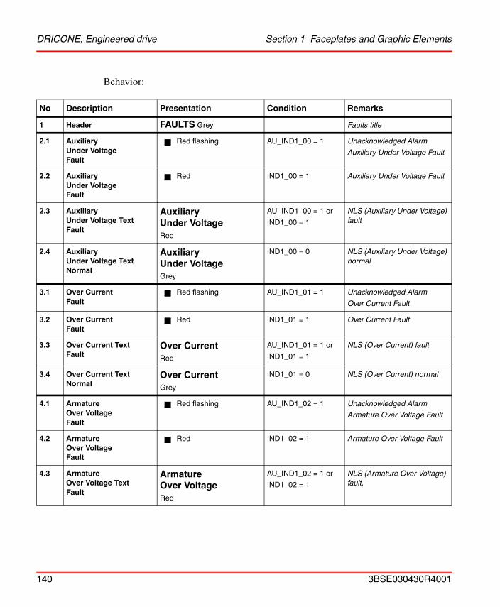
DRICONE, Engineered drive Section 1 Faceplates and Graphic Elements
Behavior:
No Description Presentation Condition Remarks
1 Header FAULTS Grey Faults title
2.1 Auxiliary Under Voltage Fault
Red flashing AU_IND1_00 = 1 Unacknowledged Alarm
Auxiliary Under Voltage Fault
2.2 Auxiliary Under VoltageFault
Red IND1_00 = 1 Auxiliary Under Voltage Fault
2.3 Auxiliary Under Voltage TextFault
Auxiliary Under VoltageRed
AU_IND1_00 = 1 or
IND1_00 = 1
NLS (Auxiliary Under Voltage) fault
2.4 Auxiliary Under Voltage TextNormal
Auxiliary Under VoltageGrey
IND1_00 = 0 NLS (Auxiliary Under Voltage) normal
3.1 Over CurrentFault
Red flashing AU_IND1_01 = 1 Unacknowledged Alarm
Over Current Fault
3.2 Over CurrentFault
Red IND1_01 = 1 Over Current Fault
3.3 Over Current TextFault
Over CurrentRed
AU_IND1_01 = 1 or
IND1_01 = 1
NLS (Over Current) fault
3.4 Over Current TextNormal
Over CurrentGrey
IND1_01 = 0 NLS (Over Current) normal
4.1 Armature Over VoltageFault
Red flashing AU_IND1_02 = 1 Unacknowledged Alarm
Armature Over Voltage Fault
4.2 Armature Over VoltageFault
Red IND1_02 = 1 Armature Over Voltage Fault
4.3 Armature Over Voltage TextFault
Armature Over VoltageRed
AU_IND1_02 = 1 or
IND1_02 = 1
NLS (Armature Over Voltage) fault.
140 3BSE030430R4001
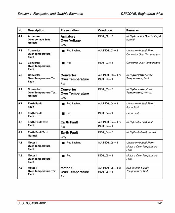
Section 1 Faceplates and Graphic Elements DRICONE, Engineered drive
4.4 Armature Over Voltage TextNormal
Armature Over VoltageGrey
IND1_02 = 0 NLS (Armature Over Voltage) normal
5.1 Converter Over TemperatureFault
Red flashing AU_IND1_03 = 1 Unacknowledged Alarm
Converter Over Temperature
5.2 Converter Over TemperatureFault
Red IND1_03 = 1 Converter Over Temperature
5.3 Converter Over Temperature Text Fault
Converter Over TemperatureRed
AU_IND1_03 = 1 or
IND1_03 = 1
NLS (Converter Over Temperature) fault.
5.4 Converter Over Temperature TextNormal
Converter Over TemperatureGrey
IND1_03 = 0 NLS (Converter Over Temperature) normal
6.1 Earth FaultFault
Red flashing AU_IND1_04 = 1 Unacknowledged Alarm
Earth Fault
6.2 Earth FaultFault
Red IND1_04 = 1 Earth Fault
6.3 Earth Fault Text Fault
Earth FaultRed
AU_IND1_04 = 1 or
IND1_04 = 1
NLS (Earth Fault) fault.
6.4 Earth Fault TextNormal
Earth FaultGrey
IND1_04 = 0 NLS (Earth Fault) normal
7.1 Motor 1 Over TemperatureFault
Red flashing AU_IND1_05 = 1 Unacknowledged Alarm
Motor 1 Over Temperature Fault
7.2 Motor 1 Over TemperatureFault
Red IND1_05 = 1 Motor 1 Over Temperature Fault
7.3 Motor 1 Over Temperature Text Fault
Motor 1 Over TemperatureRed
AU_IND1_05 = 1 or
IND1_05 = 1
NLS (Motor 1 Over Temperature) fault.
No Description Presentation Condition Remarks
3BSE030430R4001 141
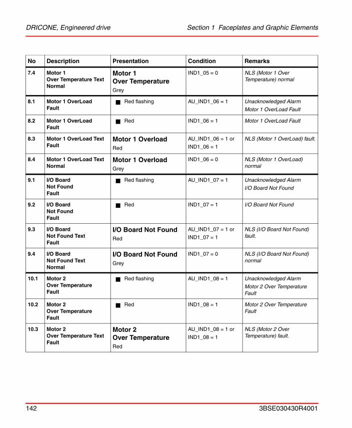
DRICONE, Engineered drive Section 1 Faceplates and Graphic Elements
7.4 Motor 1Over Temperature TextNormal
Motor 1 Over TemperatureGrey
IND1_05 = 0 NLS (Motor 1 Over Temperature) normal
8.1 Motor 1 OverLoadFault
Red flashing AU_IND1_06 = 1 Unacknowledged Alarm
Motor 1 OverLoad Fault
8.2 Motor 1 OverLoadFault
Red IND1_06 = 1 Motor 1 OverLoad Fault
8.3 Motor 1 OverLoad Text Fault
Motor 1 OverloadRed
AU_IND1_06 = 1 or
IND1_06 = 1
NLS (Motor 1 OverLoad) fault.
8.4 Motor 1 OverLoad TextNormal
Motor 1 OverloadGrey
IND1_06 = 0 NLS (Motor 1 OverLoad) normal
9.1 I/O Board Not FoundFault
Red flashing AU_IND1_07 = 1 Unacknowledged Alarm
I/O Board Not Found
9.2 I/O Board Not FoundFault
Red IND1_07 = 1 I/O Board Not Found
9.3 I/O BoardNot Found Text Fault
I/O Board Not FoundRed
AU_IND1_07 = 1 or
IND1_07 = 1
NLS (I/O Board Not Found) fault.
9.4 I/O Board Not Found TextNormal
I/O Board Not FoundGrey
IND1_07 = 0 NLS (I/O Board Not Found) normal
10.1 Motor 2 Over TemperatureFault
Red flashing AU_IND1_08 = 1 Unacknowledged Alarm
Motor 2 Over Temperature Fault
10.2 Motor 2 Over TemperatureFault
Red IND1_08 = 1 Motor 2 Over Temperature Fault
10.3 Motor 2 Over Temperature Text Fault
Motor 2 Over TemperatureRed
AU_IND1_08 = 1 or
IND1_08 = 1
NLS (Motor 2 Over Temperature) fault.
No Description Presentation Condition Remarks
142 3BSE030430R4001
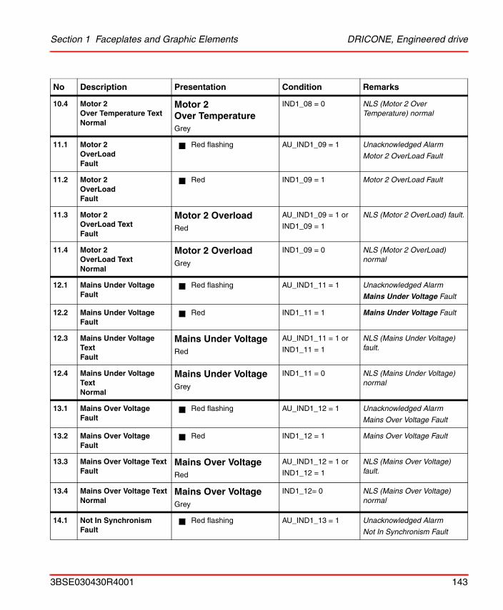
Section 1 Faceplates and Graphic Elements DRICONE, Engineered drive
10.4 Motor 2 Over Temperature TextNormal
Motor 2 Over TemperatureGrey
IND1_08 = 0 NLS (Motor 2 Over Temperature) normal
11.1 Motor 2 OverLoadFault
Red flashing AU_IND1_09 = 1 Unacknowledged Alarm
Motor 2 OverLoad Fault
11.2 Motor 2 OverLoadFault
Red IND1_09 = 1 Motor 2 OverLoad Fault
11.3 Motor 2 OverLoad Text Fault
Motor 2 OverloadRed
AU_IND1_09 = 1 or
IND1_09 = 1
NLS (Motor 2 OverLoad) fault.
11.4 Motor 2 OverLoad TextNormal
Motor 2 OverloadGrey
IND1_09 = 0 NLS (Motor 2 OverLoad) normal
12.1 Mains Under VoltageFault
Red flashing AU_IND1_11 = 1 Unacknowledged Alarm
Mains Under Voltage Fault
12.2 Mains Under VoltageFault
Red IND1_11 = 1 Mains Under Voltage Fault
12.3 Mains Under Voltage Text Fault
Mains Under VoltageRed
AU_IND1_11 = 1 or
IND1_11 = 1
NLS (Mains Under Voltage) fault.
12.4 Mains Under Voltage TextNormal
Mains Under VoltageGrey
IND1_11 = 0 NLS (Mains Under Voltage) normal
13.1 Mains Over VoltageFault
Red flashing AU_IND1_12 = 1 Unacknowledged Alarm
Mains Over Voltage Fault
13.2 Mains Over VoltageFault
Red IND1_12 = 1 Mains Over Voltage Fault
13.3 Mains Over Voltage Text Fault
Mains Over VoltageRed
AU_IND1_12 = 1 or
IND1_12 = 1
NLS (Mains Over Voltage) fault.
13.4 Mains Over Voltage TextNormal
Mains Over VoltageGrey
IND1_12= 0 NLS (Mains Over Voltage) normal
14.1 Not In SynchronismFault
Red flashing AU_IND1_13 = 1 Unacknowledged Alarm
Not In Synchronism Fault
No Description Presentation Condition Remarks
3BSE030430R4001 143
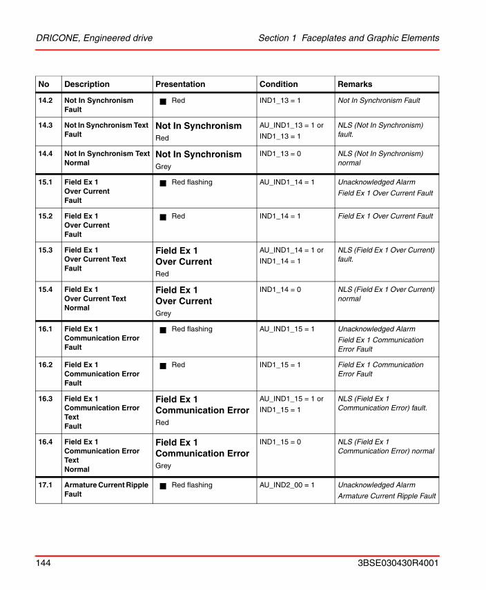
DRICONE, Engineered drive Section 1 Faceplates and Graphic Elements
14.2 Not In SynchronismFault
Red IND1_13 = 1 Not In Synchronism Fault
14.3 Not In Synchronism Text Fault
Not In SynchronismRed
AU_IND1_13 = 1 or
IND1_13 = 1
NLS (Not In Synchronism) fault.
14.4 Not In Synchronism TextNormal
Not In SynchronismGrey
IND1_13 = 0 NLS (Not In Synchronism) normal
15.1 Field Ex 1 Over CurrentFault
Red flashing AU_IND1_14 = 1 Unacknowledged Alarm
Field Ex 1 Over Current Fault
15.2 Field Ex 1 Over CurrentFault
Red IND1_14 = 1 Field Ex 1 Over Current Fault
15.3 Field Ex 1 Over Current Text Fault
Field Ex 1 Over CurrentRed
AU_IND1_14 = 1 or
IND1_14 = 1
NLS (Field Ex 1 Over Current) fault.
15.4 Field Ex 1 Over Current TextNormal
Field Ex 1 Over CurrentGrey
IND1_14 = 0 NLS (Field Ex 1 Over Current) normal
16.1 Field Ex 1 Communication ErrorFault
Red flashing AU_IND1_15 = 1 Unacknowledged Alarm
Field Ex 1 Communication Error Fault
16.2 Field Ex 1 Communication ErrorFault
Red IND1_15 = 1 Field Ex 1 Communication Error Fault
16.3 Field Ex 1 Communication Error TextFault
Field Ex 1 Communication ErrorRed
AU_IND1_15 = 1 or
IND1_15 = 1
NLS (Field Ex 1 Communication Error) fault.
16.4 Field Ex 1 Communication Error TextNormal
Field Ex 1 Communication ErrorGrey
IND1_15 = 0 NLS (Field Ex 1 Communication Error) normal
17.1 Armature Current Ripple Fault
Red flashing AU_IND2_00 = 1 Unacknowledged Alarm
Armature Current Ripple Fault
No Description Presentation Condition Remarks
144 3BSE030430R4001
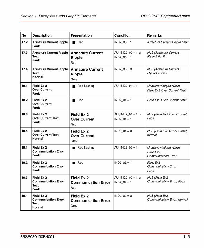
Section 1 Faceplates and Graphic Elements DRICONE, Engineered drive
17.2 Armature Current Ripple Fault
Red IND2_00 = 1 Armature Current Ripple Fault
17.3 Armature Current Ripple Text Fault
Armature Current RippleRed
AU_IND2_00 = 1 or
IND2_00 = 1
NLS (Armature Current Ripple) Fault.
17.4 Armature Current Ripple TextNormal
Armature Current RippleGrey
IND2_00 = 0 NLS (Armature Current Ripple) normal
18.1 Field Ex 2 Over CurrentFault
Red flashing AU_IND2_01 = 1 Unacknowledged Alarm
Field Ex2 Over Current Fault
18.2 Field Ex 2 Over CurrentFault
Red IND2_01 = 1 Field Ex2 Over Current Fault
18.3 Field Ex 2Over Current Text Fault
Field Ex 2 Over CurrentRed
AU_IND2_01 = 1 or
IND2_01 = 1
NLS (Field Ex2 Over Current) Fault.
18.4 Field Ex 2 Over Current TextNormal
Field Ex 2 Over CurrentGrey
IND2_01 = 0 NLS (Field Ex2 Over Current) normal
19.1 Field Ex 2 Communication ErrorFault
Red flashing AU_IND2_02 = 1 Unacknowledged Alarm
Field Ex2 Communication Error
19.2 Field Ex 2 Communication ErrorFault
Red IND2_02 = 1 Field Ex2 Communication Error
Fault
19.3 Field Ex 2 Communication Error Text Fault
Field Ex 2 Communication ErrorRed
AU_IND2_02 = 1 or
IND2_02 = 1
NLS (Field Ex2 Communication Error) Fault.
19.4 Field Ex 2 Communication Error TextNormal
Field Ex 2 Communication ErrorGrey
IND2_02 = 0 NLS (Field Ex2 Communication Error) normal
No Description Presentation Condition Remarks
3BSE030430R4001 145
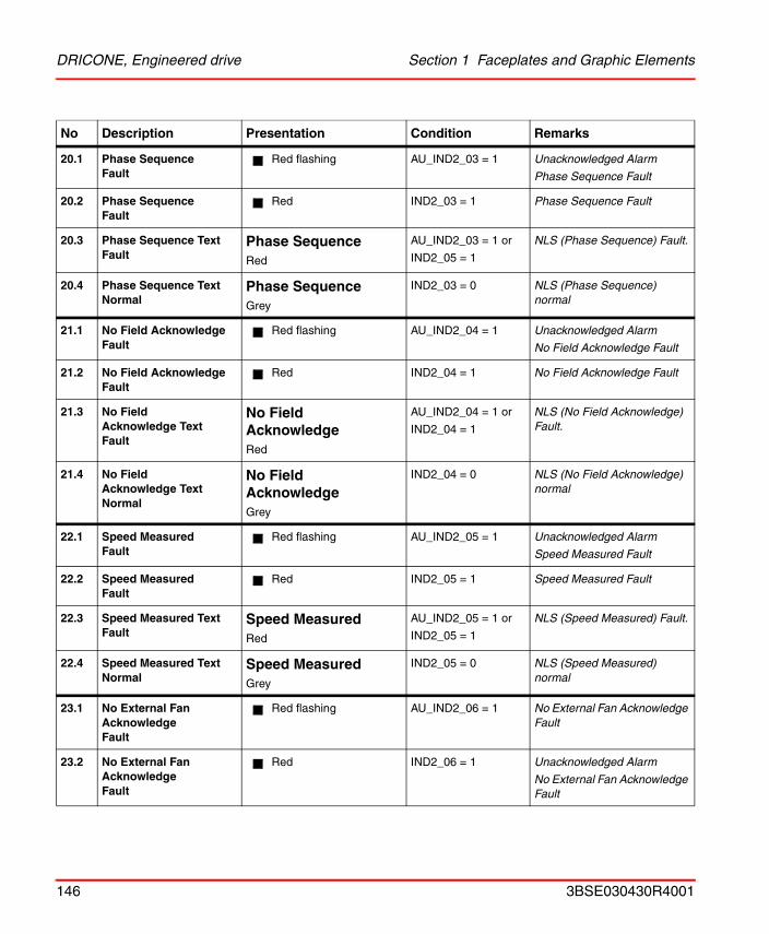
DRICONE, Engineered drive Section 1 Faceplates and Graphic Elements
20.1 Phase SequenceFault
Red flashing AU_IND2_03 = 1 Unacknowledged Alarm
Phase Sequence Fault
20.2 Phase SequenceFault
Red IND2_03 = 1 Phase Sequence Fault
20.3 Phase Sequence TextFault
Phase SequenceRed
AU_IND2_03 = 1 or
IND2_05 = 1
NLS (Phase Sequence) Fault.
20.4 Phase Sequence TextNormal
Phase SequenceGrey
IND2_03 = 0 NLS (Phase Sequence) normal
21.1 No Field AcknowledgeFault
Red flashing AU_IND2_04 = 1 Unacknowledged Alarm
No Field Acknowledge Fault
21.2 No Field AcknowledgeFault
Red IND2_04 = 1 No Field Acknowledge Fault
21.3 No Field Acknowledge TextFault
No Field AcknowledgeRed
AU_IND2_04 = 1 or
IND2_04 = 1
NLS (No Field Acknowledge) Fault.
21.4 No Field Acknowledge TextNormal
No Field AcknowledgeGrey
IND2_04 = 0 NLS (No Field Acknowledge) normal
22.1 Speed MeasuredFault
Red flashing AU_IND2_05 = 1 Unacknowledged Alarm
Speed Measured Fault
22.2 Speed MeasuredFault
Red IND2_05 = 1 Speed Measured Fault
22.3 Speed Measured Text Fault
Speed MeasuredRed
AU_IND2_05 = 1 or
IND2_05 = 1
NLS (Speed Measured) Fault.
22.4 Speed Measured TextNormal
Speed MeasuredGrey
IND2_05 = 0 NLS (Speed Measured) normal
23.1 No External Fan AcknowledgeFault
Red flashing AU_IND2_06 = 1 No External Fan Acknowledge Fault
23.2 No External Fan AcknowledgeFault
Red IND2_06 = 1 Unacknowledged Alarm
No External Fan Acknowledge Fault
No Description Presentation Condition Remarks
146 3BSE030430R4001
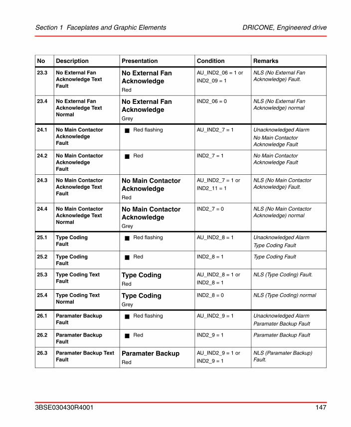
Section 1 Faceplates and Graphic Elements DRICONE, Engineered drive
23.3 No External Fan Acknowledge TextFault
No External Fan AcknowledgeRed
AU_IND2_06 = 1 or
IND2_09 = 1
NLS (No External Fan Acknowledge) Fault.
23.4 No External Fan Acknowledge TextNormal
No External Fan AcknowledgeGrey
IND2_06 = 0 NLS (No External Fan Acknowledge) normal
24.1 No Main Contactor AcknowledgeFault
Red flashing AU_IND2_7 = 1 Unacknowledged Alarm
No Main Contactor Acknowledge Fault
24.2 No Main Contactor AcknowledgeFault
Red IND2_7 = 1 No Main Contactor Acknowledge Fault
24.3 No Main Contactor Acknowledge TextFault
No Main Contactor AcknowledgeRed
AU_IND2_7 = 1 or
IND2_11 = 1
NLS (No Main Contactor Acknowledge) Fault.
24.4 No Main Contactor Acknowledge TextNormal
No Main Contactor AcknowledgeGrey
IND2_7 = 0 NLS (No Main Contactor Acknowledge) normal
25.1 Type CodingFault
Red flashing AU_IND2_8 = 1 Unacknowledged Alarm
Type Coding Fault
25.2 Type CodingFault
Red IND2_8 = 1 Type Coding Fault
25.3 Type Coding TextFault
Type CodingRed
AU_IND2_8 = 1 or
IND2_8 = 1
NLS (Type Coding) Fault.
25.4 Type Coding TextNormal
Type CodingGrey
IND2_8 = 0 NLS (Type Coding) normal
26.1 Paramater BackupFault
Red flashing AU_IND2_9 = 1 Unacknowledged Alarm
Paramater Backup Fault
26.2 Paramater BackupFault
Red IND2_9 = 1 Paramater Backup Fault
26.3 Paramater Backup TextFault
Paramater BackupRed
AU_IND2_9 = 1 or
IND2_9 = 1
NLS (Paramater Backup) Fault.
No Description Presentation Condition Remarks
3BSE030430R4001 147
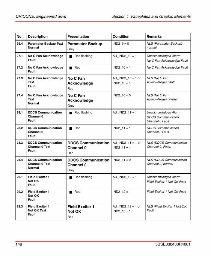
DRICONE, Engineered drive Section 1 Faceplates and Graphic Elements
26.4 Paramater Backup TextNormal
Paramater BackupGrey
IND2_9 = 0 NLS (Paramater Backup) normal
27.1 No C Fan AcknowledgeFault
Red flashing AU_IND2_10 = 1 Unacknowledged Alarm
No C Fan Acknowledge Fault
27.2 No C Fan AcknowledgeFault
Red IND2_10 = 1 No C Fan Acknowledge Fault
27.3 No C Fan Acknowledge TextFault
No C Fan AcknowledgeRed
AU_IND2_10 = 1 or
IND2_10 = 1
NLS (No C Fan Acknowledge) Fault.
27.4 No C Fan Acknowledge TextNormal
No C Fan AcknowledgeGrey
IND2_10 = 0 NLS (No C Fan Acknowledge) normal
28.1 DDCS Communication Channel 0Fault
Red flashing AU_IND2_11 = 1 Unacknowledged Alarm
DDCS Communication Channel 0 Fault
28.2 DDCS Communication Channel 0Fault
Red IND2_11 = 1 DDCS Communication Channel 0 Fault
28.3 DDCS Communication Channel 0 TextFault
DDCS Communication Channel 0Red
AU_IND2_11 = 1 or
IND2_11 = 1
NLS (DDCS Communication Channel 0) Fault.
28.4 DDCS Communication Channel 0 TextNormal
DDCS Communication Channel 0Grey
IND2_11 = 0 NLS (DDCS Communication Channel 0) normal
29.1 Field Exciter 1 Not OKFault
Red flashing AU_IND2_12 = 1 Unacknowledged Alarm
Field Exciter 1 Not OK Fault
29.2 Field Exciter 1 Not OKFault
Red IND2_12 = 1 Field Exciter 1 Not OK Fault
29.3 Field Exciter 1 Not OK Text Fault
Field Exciter 1 Not OKRed
AU_IND2_12 = 1 or
IND2_13 = 1
NLS (Field Exciter 1 Not OK) Fault.
No Description Presentation Condition Remarks
148 3BSE030430R4001
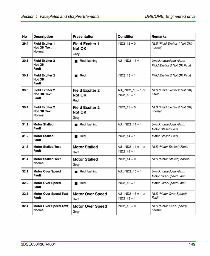
Section 1 Faceplates and Graphic Elements DRICONE, Engineered drive
29.4 Field Exciter 1 Not OK TextNormal
Field Exciter 1 Not OKGrey
IND2_12 = 0 NLS (Field Exciter 1 Not OK) normal
30.1 Field Exciter 2 Not OKFault
Red flashing AU_IND2_13 = 1 Unacknowledged Alarm
Field Exciter 2 Not OK Fault
30.2 Field Exciter 2 Not OKFault
Red IND2_13 = 1 Field Exciter 2 Not OK Fault
30.3 Field Exciter 2 Not OK Text Fault
Field Exciter 2 Not OKRed
AU_IND2_13 = 1 or
IND2_13 = 1
NLS (Field Exciter 2 Not OK) Fault.
30.4 Field Exciter 2 Not OK TextNormal
Field Exciter 2 Not OKGrey
IND2_13 = 0 NLS (Field Exciter 2 Not OK) normal
31.1 Motor StalledFault
Red flashing AU_IND2_14 = 1 Unacknowledged Alarm
Motor Stalled Fault
31.2 Motor StalledFault
Red IND2_14 = 1 Motor Stalled Fault
31.3 Motor Stalled TextFault
Motor StalledRed
AU_IND2_14 = 1 or
IND2_14 = 1
NLS (Motor Stalled) Fault.
31.4 Motor Stalled TextNormal
Motor StalledGrey
IND2_14 = 0 NLS (Motor Stalled) normal
32.1 Motor Over SpeedFault
Red flashing AU_IND2_15 = 1 Unacknowledged Alarm
Motor Over Speed Fault
32.2 Motor Over SpeedFault
Red IND2_15 = 1 Motor Over Speed Fault
32.3 Motor Over Speed TextFault
Motor Over SpeedRed
AU_IND2_15 = 1 or
IND2_15 = 1
NLS (Motor Over Speed) Fault.
32.4 Motor Over Speed TextNormal
Motor Over SpeedGrey
IND2_15 = 0 NLS (Motor Over Speed) normal
No Description Presentation Condition Remarks
3BSE030430R4001 149
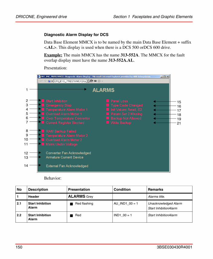
DRICONE, Engineered drive Section 1 Faceplates and Graphic Elements
Diagnostic Alarm Display for DCS
Data Base Element MMCX is to be named by the main Data Base Element + suffix <.AL>. This display is used when there is a DCS 500 orDCS 600 drive.
Example: The main MMCX has the name 313-552A. The MMCX for the fault overlap display must have the name 313-552A.AL.
Presentation:
Behavior:
No Description Presentation Condition Remarks
1 Header ALARMS Grey Alarms title.
2.1 Start InhibitionAlarm
Red flashing AU_IND1_00 = 1 Unacknowledged Alarm
Start InhibitionAlarm
2.2 Start InhibitionAlarm
Red IND1_00 = 1 Start InhibitionAlarm
1
234567
89
1011
1213
14
151617181921
150 3BSE030430R4001
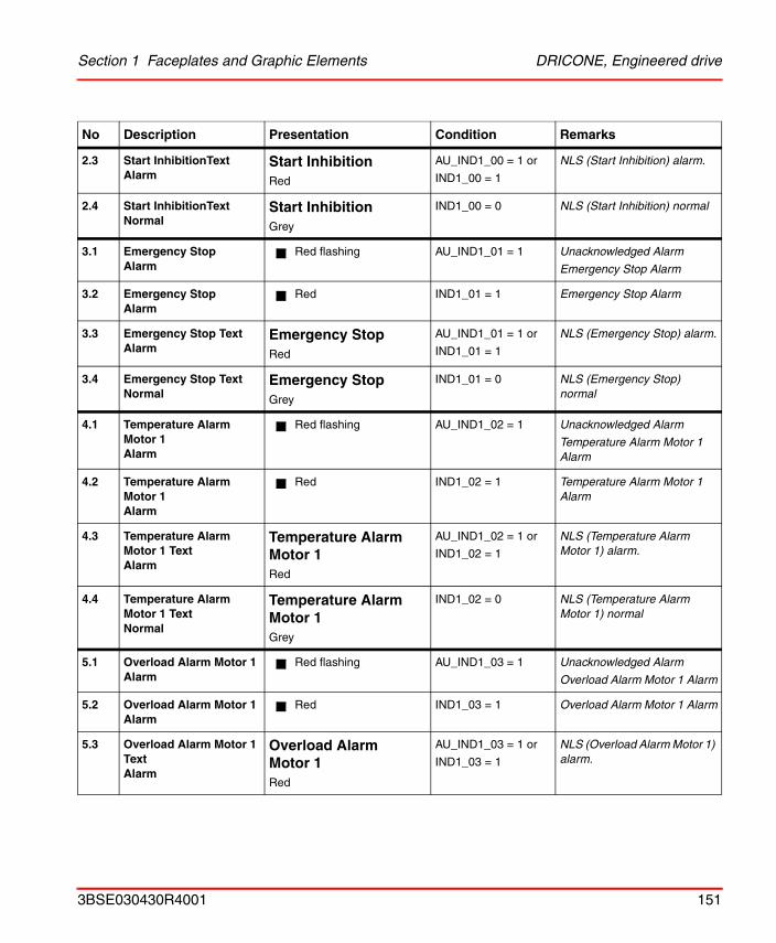
Section 1 Faceplates and Graphic Elements DRICONE, Engineered drive
2.3 Start InhibitionText Alarm
Start InhibitionRed
AU_IND1_00 = 1 or
IND1_00 = 1
NLS (Start Inhibition) alarm.
2.4 Start InhibitionTextNormal
Start InhibitionGrey
IND1_00 = 0 NLS (Start Inhibition) normal
3.1 Emergency StopAlarm
Red flashing AU_IND1_01 = 1 Unacknowledged Alarm
Emergency Stop Alarm
3.2 Emergency StopAlarm
Red IND1_01 = 1 Emergency Stop Alarm
3.3 Emergency Stop TextAlarm
Emergency StopRed
AU_IND1_01 = 1 or
IND1_01 = 1
NLS (Emergency Stop) alarm.
3.4 Emergency Stop TextNormal
Emergency StopGrey
IND1_01 = 0 NLS (Emergency Stop) normal
4.1 Temperature Alarm Motor 1Alarm
Red flashing AU_IND1_02 = 1 Unacknowledged Alarm
Temperature Alarm Motor 1 Alarm
4.2 Temperature Alarm Motor 1Alarm
Red IND1_02 = 1 Temperature Alarm Motor 1 Alarm
4.3 Temperature Alarm Motor 1 TextAlarm
Temperature Alarm Motor 1Red
AU_IND1_02 = 1 or
IND1_02 = 1
NLS (Temperature Alarm Motor 1) alarm.
4.4 Temperature Alarm Motor 1 TextNormal
Temperature Alarm Motor 1Grey
IND1_02 = 0 NLS (Temperature Alarm Motor 1) normal
5.1 Overload Alarm Motor 1Alarm
Red flashing AU_IND1_03 = 1 Unacknowledged Alarm
Overload Alarm Motor 1 Alarm
5.2 Overload Alarm Motor 1Alarm
Red IND1_03 = 1 Overload Alarm Motor 1 Alarm
5.3 Overload Alarm Motor 1 Text Alarm
Overload Alarm Motor 1Red
AU_IND1_03 = 1 or
IND1_03 = 1
NLS (Overload Alarm Motor 1) alarm.
No Description Presentation Condition Remarks
3BSE030430R4001 151
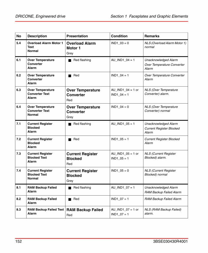
DRICONE, Engineered drive Section 1 Faceplates and Graphic Elements
5.4 Overload Alarm Motor 1 TextNormal
Overload Alarm Motor 1Grey
IND1_03 = 0 NLS (Overload Alarm Motor 1) normal
6.1 Over Temperature ConverterAlarm
Red flashing AU_IND1_04 = 1 Unacknowledged Alarm
Over Temperature Converter Alarm
6.2 Over Temperature ConverterAlarm
Red IND1_04 = 1 Over Temperature Converter Alarm
6.3 Over Temperature Converter TextAlarm
Over Temperature ConverterRed
AU_IND1_04 = 1 or
IND1_04 = 1
NLS (Over Temperature Converter) alarm.
6.4 Over Temperature Converter TextNormal
Over Temperature ConverterGrey
IND1_04 = 0 NLS (Over Temperature Converter) normal
7.1 Current Register BlockedAlarm
Red flashing AU_IND1_05 = 1 Unacknowledged Alarm
Current Register Blocked Alarm
7.2 Current Register BlockedAlarm
Red IND1_05 = 1 Current Register Blocked Alarm
7.3 Current Register Blocked Text Alarm
Current Register BlockedRed
AU_IND1_05 = 1 or
IND1_05 = 1
NLS (Current Register Blocked) alarm.
7.4 Current Register Blocked TextNormal
Current Register BlockedGrey
IND1_05 = 0 NLS (Current Register Blocked) normal
8.1 RAM Backup FailedAlarm
Red flashing AU_IND1_07 = 1 Unacknowledged Alarm
RAM Backup Failed Alarm
8.2 RAM Backup FailedAlarm
Red IND1_07 = 1 RAM Backup Failed Alarm
8.3 RAM Backup Failed TextAlarm
RAM Backup FailedRed
AU_IND1_07 = 1 or
IND1_07 = 1
NLS (RAM Backup Failed) alarm.
No Description Presentation Condition Remarks
152 3BSE030430R4001
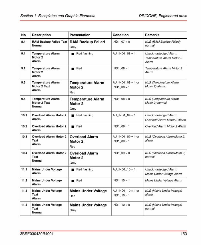
Section 1 Faceplates and Graphic Elements DRICONE, Engineered drive
8.4 RAM Backup Failed TextNormal
RAM Backup FailedGrey
IND1_07 = 0 NLS (RAM Backup Failed) normal
9.1 Temperature Alarm Motor 2Alarm
Red flashing AU_IND1_08 = 1 Unacknowledged Alarm
Temperature Alarm Motor 2 Alarm
9.2 Temperature Alarm Motor 2Alarm
Red IND1_08 = 1 Temperature Alarm Motor 2 Alarm
9.3 Temperature Alarm Motor 2 TextAlarm
Temperature Alarm Motor 2Red
AU_IND1_08 = 1 or
IND1_08 = 1
NLS (Temperature Alarm Motor 2) alarm.
9.4 Temperature Alarm Motor 2 TextNormal
Temperature Alarm Motor 2Grey
IND1_08 = 0 NLS (Temperature Alarm Motor 2) normal
10.1 Overload Alarm Motor 2Alarm
Red flashing AU_IND1_09 = 1 Unacknowledged Alarm
Overload Alarm Motor 2 Alarm
10.2 Overload Alarm Motor 2Alarm
Red IND1_09 = 1 Overload Alarm Motor 2 Alarm
10.3 Overload Alarm Motor 2 Text Alarm
Overload Alarm Motor 2Red
AU_IND1_09 = 1 or
IND1_09 = 1
NLS (Overload Alarm Motor 2) alarm.
10.4 Overload Alarm Motor 2 TextNormal
Overload Alarm Motor 2Grey
IND1_09 = 0 NLS (Overload Alarm Motor 2) normal
11.1 Mains Under VoltageAlarm
Red flashing AU_IND1_10 = 1 Unacknowledged Alarm
Mains Under Voltage Alarm
11.2 Mains Under VoltageAlarm
Red IND1_10 = 1 Mains Under Voltage Alarm
11.3 Mains Under Voltage TextAlarm
Mains Under VoltageRed
AU_IND1_10 = 1 or
IND1_10 = 1
NLS (Mains Under Voltage) alarm.
11.4 Mains Under Voltage TextNormal
Mains Under VoltageGrey
IND1_10 = 0 NLS (Mains Under Voltage) normal
No Description Presentation Condition Remarks
3BSE030430R4001 153
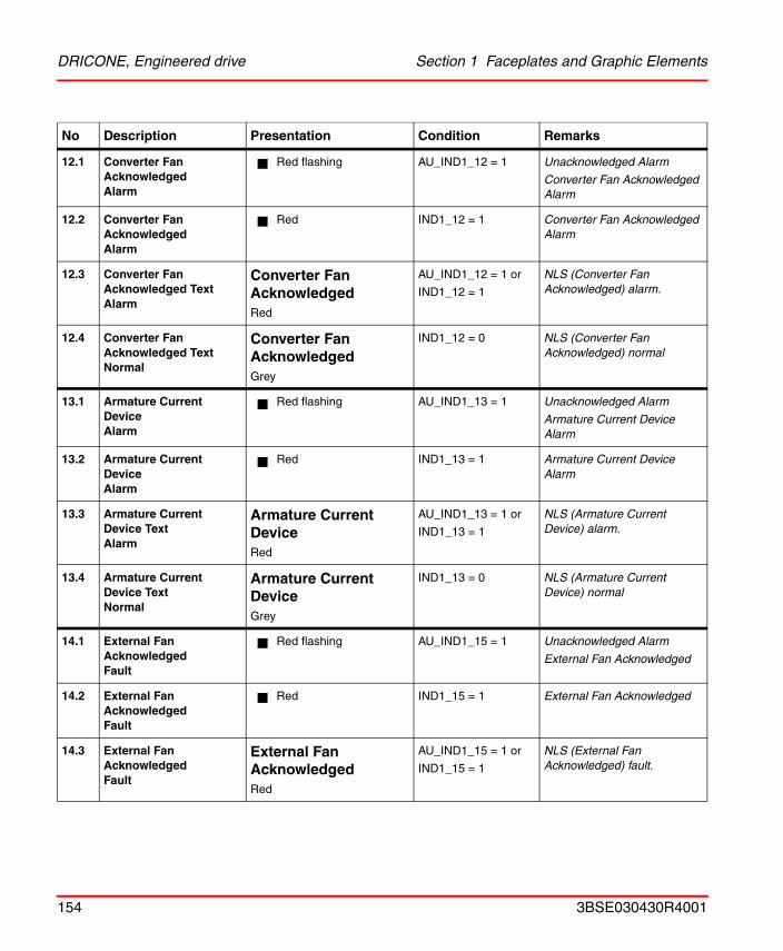
DRICONE, Engineered drive Section 1 Faceplates and Graphic Elements
12.1 Converter Fan AcknowledgedAlarm
Red flashing AU_IND1_12 = 1 Unacknowledged Alarm
Converter Fan Acknowledged Alarm
12.2 Converter Fan AcknowledgedAlarm
Red IND1_12 = 1 Converter Fan Acknowledged Alarm
12.3 Converter Fan Acknowledged TextAlarm
Converter Fan AcknowledgedRed
AU_IND1_12 = 1 or
IND1_12 = 1
NLS (Converter Fan Acknowledged) alarm.
12.4 Converter Fan Acknowledged TextNormal
Converter Fan AcknowledgedGrey
IND1_12 = 0 NLS (Converter Fan Acknowledged) normal
13.1 Armature Current DeviceAlarm
Red flashing AU_IND1_13 = 1 Unacknowledged Alarm
Armature Current Device Alarm
13.2 Armature Current DeviceAlarm
Red IND1_13 = 1 Armature Current Device Alarm
13.3 Armature Current Device TextAlarm
Armature Current DeviceRed
AU_IND1_13 = 1 or
IND1_13 = 1
NLS (Armature Current Device) alarm.
13.4 Armature Current Device TextNormal
Armature Current DeviceGrey
IND1_13 = 0 NLS (Armature Current Device) normal
14.1 External Fan AcknowledgedFault
Red flashing AU_IND1_15 = 1 Unacknowledged Alarm
External Fan Acknowledged
14.2 External Fan AcknowledgedFault
Red IND1_15 = 1 External Fan Acknowledged
14.3 External Fan AcknowledgedFault
External Fan AcknowledgedRed
AU_IND1_15 = 1 or
IND1_15 = 1
NLS (External Fan Acknowledged) fault.
No Description Presentation Condition Remarks
154 3BSE030430R4001
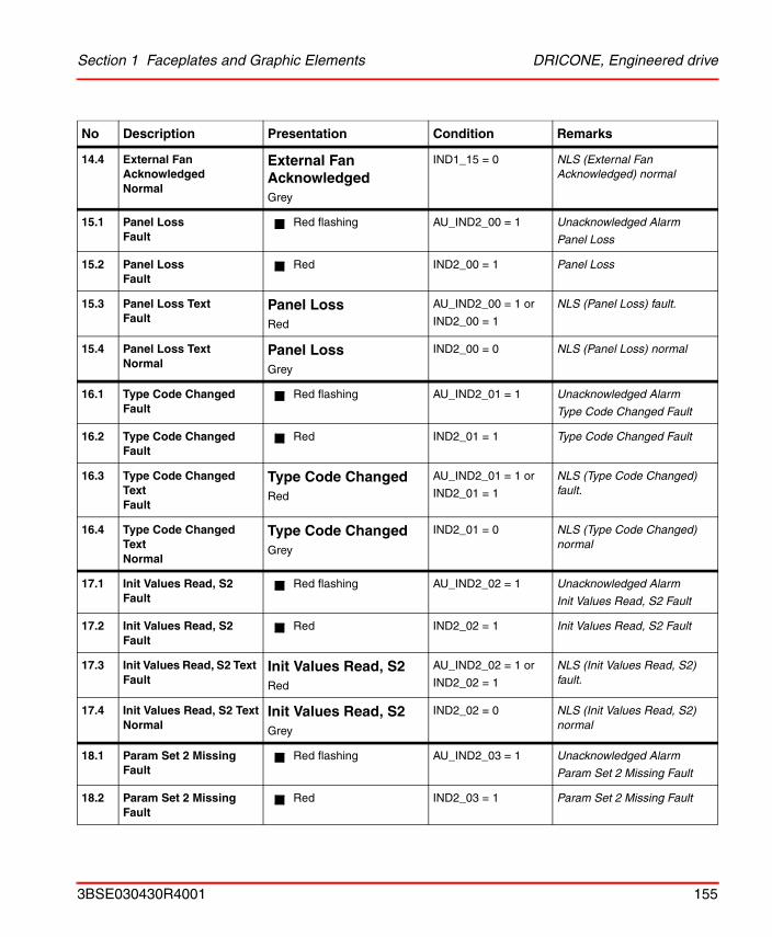
Section 1 Faceplates and Graphic Elements DRICONE, Engineered drive
14.4 External Fan Acknowledged Normal
External Fan AcknowledgedGrey
IND1_15 = 0 NLS (External Fan Acknowledged) normal
15.1 Panel LossFault
Red flashing AU_IND2_00 = 1 Unacknowledged Alarm
Panel Loss
15.2 Panel LossFault
Red IND2_00 = 1 Panel Loss
15.3 Panel Loss TextFault
Panel LossRed
AU_IND2_00 = 1 or
IND2_00 = 1
NLS (Panel Loss) fault.
15.4 Panel Loss TextNormal
Panel LossGrey
IND2_00 = 0 NLS (Panel Loss) normal
16.1 Type Code ChangedFault
Red flashing AU_IND2_01 = 1 Unacknowledged Alarm
Type Code Changed Fault
16.2 Type Code ChangedFault
Red IND2_01 = 1 Type Code Changed Fault
16.3 Type Code Changed TextFault
Type Code ChangedRed
AU_IND2_01 = 1 or
IND2_01 = 1
NLS (Type Code Changed) fault.
16.4 Type Code Changed TextNormal
Type Code ChangedGrey
IND2_01 = 0 NLS (Type Code Changed) normal
17.1 Init Values Read, S2Fault
Red flashing AU_IND2_02 = 1 Unacknowledged Alarm
Init Values Read, S2 Fault
17.2 Init Values Read, S2Fault
Red IND2_02 = 1 Init Values Read, S2 Fault
17.3 Init Values Read, S2 Text Fault
Init Values Read, S2Red
AU_IND2_02 = 1 or
IND2_02 = 1
NLS (Init Values Read, S2) fault.
17.4 Init Values Read, S2 TextNormal
Init Values Read, S2Grey
IND2_02 = 0 NLS (Init Values Read, S2) normal
18.1 Param Set 2 MissingFault
Red flashing AU_IND2_03 = 1 Unacknowledged Alarm
Param Set 2 Missing Fault
18.2 Param Set 2 MissingFault
Red IND2_03 = 1 Param Set 2 Missing Fault
No Description Presentation Condition Remarks
3BSE030430R4001 155
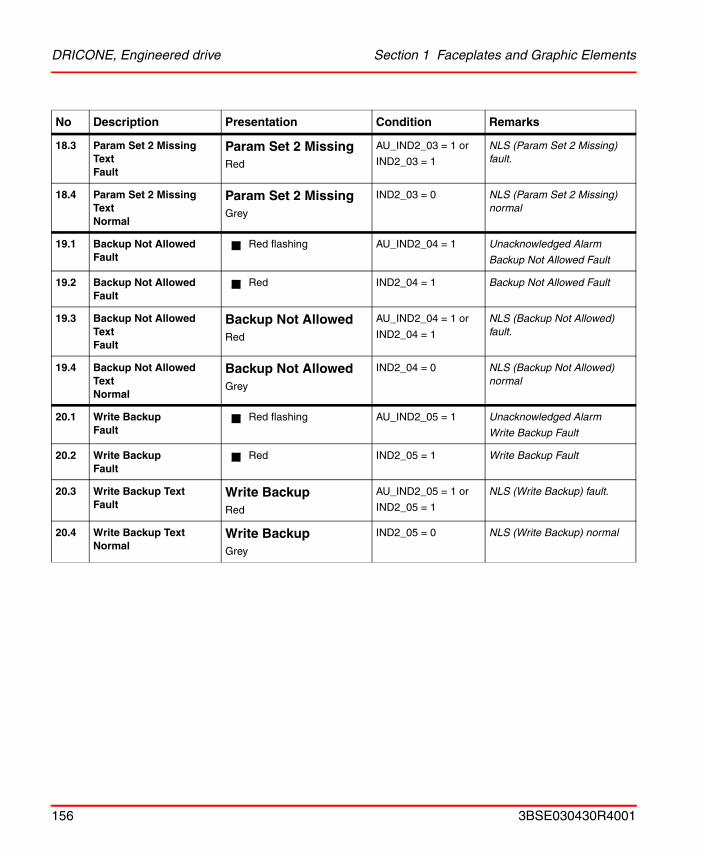
DRICONE, Engineered drive Section 1 Faceplates and Graphic Elements
18.3 Param Set 2 Missing TextFault
Param Set 2 MissingRed
AU_IND2_03 = 1 or
IND2_03 = 1
NLS (Param Set 2 Missing) fault.
18.4 Param Set 2 Missing TextNormal
Param Set 2 MissingGrey
IND2_03 = 0 NLS (Param Set 2 Missing) normal
19.1 Backup Not AllowedFault
Red flashing AU_IND2_04 = 1 Unacknowledged Alarm
Backup Not Allowed Fault
19.2 Backup Not AllowedFault
Red IND2_04 = 1 Backup Not Allowed Fault
19.3 Backup Not Allowed TextFault
Backup Not AllowedRed
AU_IND2_04 = 1 or
IND2_04 = 1
NLS (Backup Not Allowed) fault.
19.4 Backup Not Allowed TextNormal
Backup Not AllowedGrey
IND2_04 = 0 NLS (Backup Not Allowed) normal
20.1 Write BackupFault
Red flashing AU_IND2_05 = 1 Unacknowledged Alarm
Write Backup Fault
20.2 Write BackupFault
Red IND2_05 = 1 Write Backup Fault
20.3 Write Backup Text Fault
Write BackupRed
AU_IND2_05 = 1 or
IND2_05 = 1
NLS (Write Backup) fault.
20.4 Write Backup TextNormal
Write BackupGrey
IND2_05 = 0 NLS (Write Backup) normal
No Description Presentation Condition Remarks
156 3BSE030430R4001
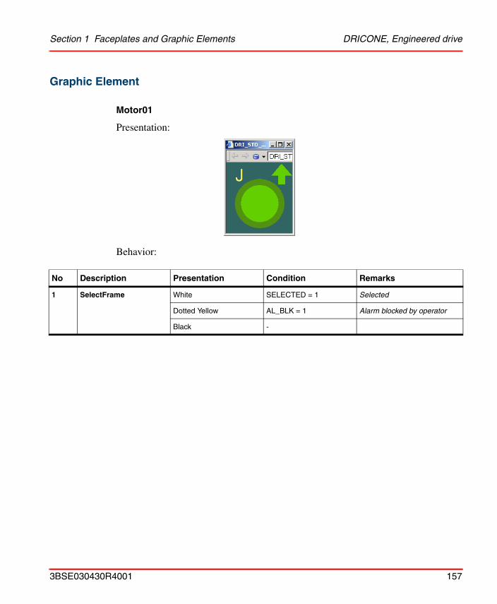
Section 1 Faceplates and Graphic Elements DRICONE, Engineered drive
Graphic Element
Motor01
Presentation:
Behavior:
No Description Presentation Condition Remarks
1 SelectFrame White SELECTED = 1 Selected
Dotted Yellow AL_BLK = 1 Alarm blocked by operator
Black -
3BSE030430R4001 157
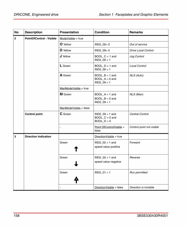
DRICONE, Engineered drive Section 1 Faceplates and Graphic Elements
2 PointOfControl - Visible ModeVisible = true
O Yellow IND2_00= 0 Out of service
D Yellow IND2_09= 0 Drive Local Control
J Yellow BOOL_C = 1 andIND2_09 = 1
Jog Control
L Green BOOL_D = 1 andIND2_09 = 1
Local Control
A Green BOOL_B = 1 andBOOL_A = 0 andIND2_09 = 1
NLS (Auto)
ManModeVisible = true
M Green BOOL_A = 1 and
BOOL_B = 0 andIND2_09 = 1
NLS (Man)
ManModeVisible = false
Control point C Green IND2_09 = 1 andBOOL_C = 0 andBOOL_D = 0
Central Control
- Point OfControlVisible = false
Control point not visible
3 Direction Indication DirectionVisible = true
Green IND2_02 = 1 and
speed value positive
Forward
Green IND2_02 = 1 and
speed value negative
Reverse
Green IND2_01 = 1 Run permitted
- DirectionVisible = false Direction is invisible
No Description Presentation Condition Remarks
158 3BSE030430R4001
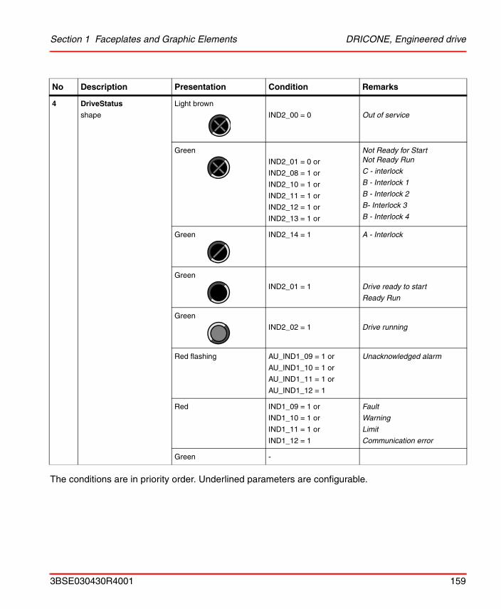
Section 1 Faceplates and Graphic Elements DRICONE, Engineered drive
The conditions are in priority order. Underlined parameters are configurable.
4 DriveStatus
shape
Light brown
IND2_00 = 0 Out of service
Green
IND2_01 = 0 or
IND2_08 = 1 or
IND2_10 = 1 or
IND2_11 = 1 or
IND2_12 = 1 or
IND2_13 = 1 or
Not Ready for StartNot Ready Run
C - interlock
B - Interlock 1
B - Interlock 2
B- Interlock 3
B - Interlock 4
Green IND2_14 = 1 A - Interlock
Green
IND2_01 = 1 Drive ready to start
Ready Run
Green
IND2_02 = 1 Drive running
Red flashing AU_IND1_09 = 1 or
AU_IND1_10 = 1 or
AU_IND1_11 = 1 or
AU_IND1_12 = 1
Unacknowledged alarm
Red IND1_09 = 1 or
IND1_10 = 1 or
IND1_11 = 1 or
IND1_12 = 1
Fault
Warning
Limit
Communication error
Green -
No Description Presentation Condition Remarks
3BSE030430R4001 159
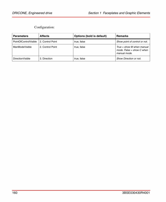
DRICONE, Engineered drive Section 1 Faceplates and Graphic Elements
Configuration:
Parameters Affects Options (bold is default) Remarks
PointOfControlVisible 2. Control Point true, false Show point of control or not.
ManModeVisible 2. Control Point true, false True = show M when manual mode. False = show C when manual mode.
DirectionVisible 3. Direction true, false Show Direction or not.
160 3BSE030430R4001
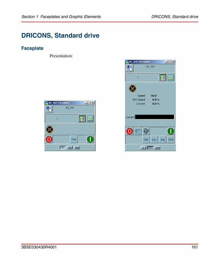
Section 1 Faceplates and Graphic Elements DRICONS, Standard drive
DRICONS, Standard drive
Faceplate
Presentation:
3BSE030430R4001 161
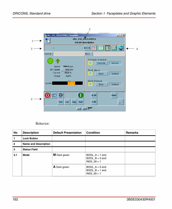
DRICONS, Standard drive Section 1 Faceplates and Graphic Elements
Behavior:
No Description Default Presentation Condition Remarks
1 Lock Button
2 Name and Description
3 Status Field
3.1 Mode M Dark green BOOL_A = 1 andBOOL_B = 0 andIND2_09 = 1
A Dark green BOOL_A = 0 andBOOL_B = 1 andIND2_09 = 1
1
3
5
4
2
162 3BSE030430R4001

Section 1 Faceplates and Graphic Elements DRICONS, Standard drive
3.2 Control point O Light brown IND2_00 = 0 Out of service.
D Yellow IND2_09 = 0 Drive local
J Yellow IND2_09 = 1 andBOOL_C = 1
Jog running from motor place
L Dark green IND2_09 = 1 andBOOL_D = 1
Local controlled from local panel
C Dark green IND2_09 = 1 andBOOL_C = 0 andBOOL_D = 0
Central controlled from operator’s panel
3.3 Print Blk P Yellow PRINT_BLK = 1
3.4 Interlock indications X Yellow (IND2_12 = 1 and IND2_02 = 1 and BOOL_F = 1and IND2_15 = 0)
or
(IND2_13 = 1 and IND2_02 = 1 and BOOL_F = 1)
B- Interlock 3
B - Interlock 4
X Green (IND2_08 = 1) or(IND2_10 = 1 and IND2_15 = 0 ) orIND2_11 = 1 or(IND2_12 = 1 and BOOL_F = 0 and IND2_15 = 0 ) or(IND2_12 = 1 and IND2_02 = 0 and BOOL_F = 1and IND2_15 = 0) or(IND2_13 = 1 and BOOL_F = 0)or(IND2_13 = 1 and IND2_02 = 0 and BOOL_F = 1)orIND2_14 = 1
C - interlock
B - Interlock 1
B - Interlock 2
B- Interlock 3
B - Interlock 4
IA- Interlock
BX Red IND1_15 = 1 Override Interlock and Interlock active
BX Yellow (BOOL_C = 1 or IND2_15 = 1) and IND1_15=0
Override Interlock and Interlock active
No Description Default Presentation Condition Remarks
3BSE030430R4001 163
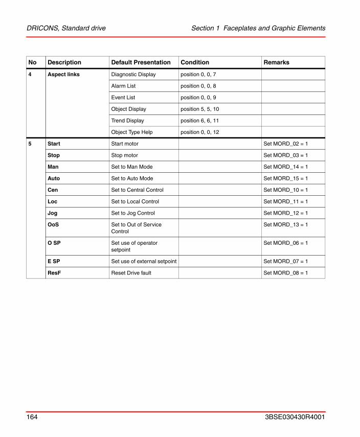
DRICONS, Standard drive Section 1 Faceplates and Graphic Elements
4 Aspect links Diagnostic Display position 0, 0, 7
Alarm List position 0, 0, 8
Event List position 0, 0, 9
Object Display position 5, 5, 10
Trend Display position 6, 6, 11
Object Type Help position 0, 0, 12
5 Start Start motor Set MORD_02 = 1
Stop Stop motor Set MORD_03 = 1
Man Set to Man Mode Set MORD_14 = 1
Auto Set to Auto Mode Set MORD_15 = 1
Cen Set to Central Control Set MORD_10 = 1
Loc Set to Local Control Set MORD_11 = 1
Jog Set to Jog Control Set MORD_12 = 1
OoS Set to Out of Service Control
Set MORD_13 = 1
O SP Set use of operator setpoint
Set MORD_06 = 1
E SP Set use of external setpoint Set MORD_07 = 1
ResF Reset Drive fault Set MORD_08 = 1
No Description Default Presentation Condition Remarks
164 3BSE030430R4001
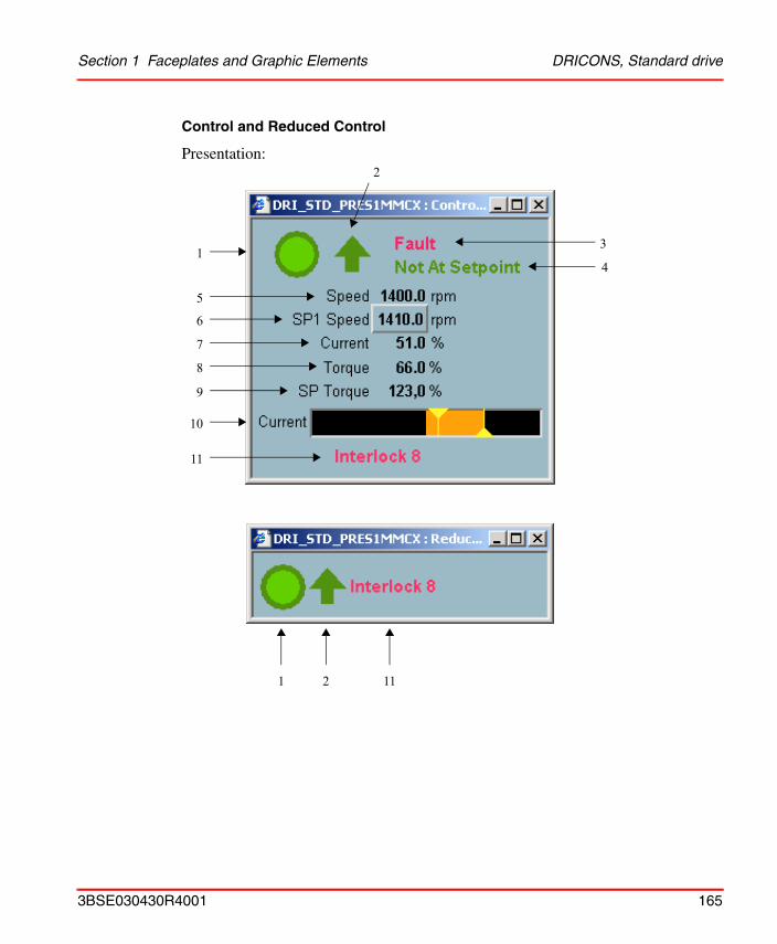
Section 1 Faceplates and Graphic Elements DRICONS, Standard drive
Control and Reduced Control
Presentation:
1
5
6
7
8
9
10
11
3
4
2
2 111
3BSE030430R4001 165
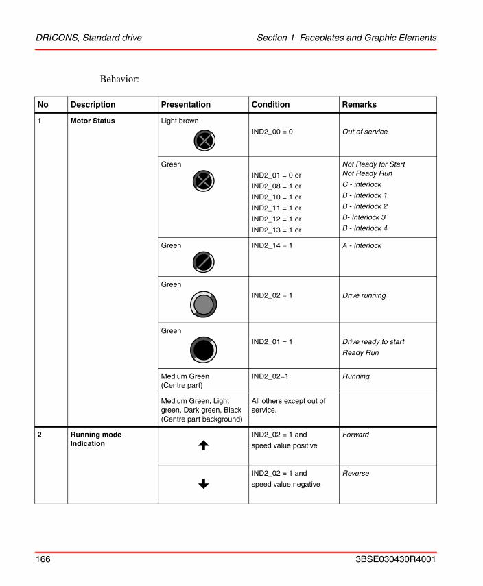
DRICONS, Standard drive Section 1 Faceplates and Graphic Elements
Behavior:
No Description Presentation Condition Remarks
1 Motor Status Light brown
IND2_00 = 0 Out of service
Green
IND2_01 = 0 or
IND2_08 = 1 or
IND2_10 = 1 or
IND2_11 = 1 or
IND2_12 = 1 or
IND2_13 = 1 or
Not Ready for StartNot Ready Run
C - interlock
B - Interlock 1
B - Interlock 2
B- Interlock 3
B - Interlock 4
Green IND2_14 = 1 A - Interlock
Green
IND2_02 = 1 Drive running
Green
IND2_01 = 1 Drive ready to start
Ready Run
Medium Green(Centre part)
IND2_02=1 Running
Medium Green, Light green, Dark green, Black (Centre part background)
All others except out of service.
2 Running mode Indication
IND2_02 = 1 and
speed value positive
Forward
IND2_02 = 1 and
speed value negative
Reverse
166 3BSE030430R4001
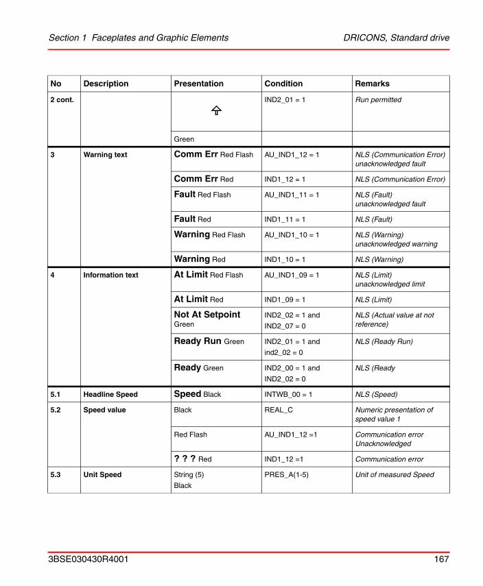
Section 1 Faceplates and Graphic Elements DRICONS, Standard drive
2 cont. IND2_01 = 1 Run permitted
Green
3 Warning text Comm Err Red Flash AU_IND1_12 = 1 NLS (Communication Error) unacknowledged fault
Comm Err Red IND1_12 = 1 NLS (Communication Error)
Fault Red Flash AU_IND1_11 = 1 NLS (Fault) unacknowledged fault
Fault Red IND1_11 = 1 NLS (Fault)
Warning Red Flash AU_IND1_10 = 1 NLS (Warning) unacknowledged warning
Warning Red IND1_10 = 1 NLS (Warning)
4 Information text At Limit Red Flash AU_IND1_09 = 1 NLS (Limit) unacknowledged limit
At Limit Red IND1_09 = 1 NLS (Limit)
Not At Setpoint Green
IND2_02 = 1 and
IND2_07 = 0
NLS (Actual value at not reference)
Ready Run Green IND2_01 = 1 and
ind2_02 = 0
NLS (Ready Run)
Ready Green IND2_00 = 1 and
IND2_02 = 0
NLS (Ready
5.1 Headline Speed Speed Black INTWB_00 = 1 NLS (Speed)
5.2 Speed value Black REAL_C Numeric presentation of speed value 1
Red Flash AU_IND1_12 =1 Communication error Unacknowledged
? ? ? Red IND1_12 =1 Communication error
5.3 Unit Speed String (5)
Black
PRES_A(1-5) Unit of measured Speed
No Description Presentation Condition Remarks
3BSE030430R4001 167
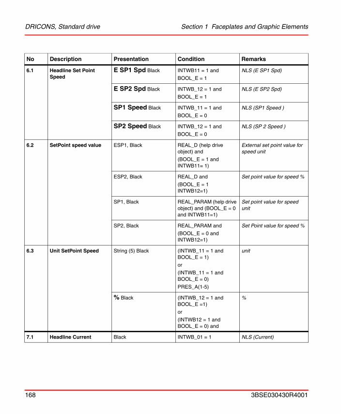
DRICONS, Standard drive Section 1 Faceplates and Graphic Elements
6.1 Headline Set Point Speed
E SP1 Spd Black INTWB11 = 1 and
BOOL_E = 1
NLS (E SP1 Spd)
E SP2 Spd Black INTWB_12 = 1 and
BOOL_E = 1
NLS (E SP2 Spd)
SP1 Speed Black INTWB_11 = 1 and
BOOL_E = 0
NLS (SP1 Speed )
SP2 Speed Black INTWB_12 = 1 and
BOOL_E = 0
NLS (SP 2 Speed )
6.2 SetPoint speed value ESP1, Black REAL_D (help drive object) and
(BOOL_E = 1 and INTWB11= 1)
External set point value for speed unit
ESP2, Black REAL_D and
(BOOL_E = 1 INTWB12=1)
Set point value for speed %
SP1, Black REAL_PARAM (help drive object) and (BOOL_E = 0 and INTWB11=1)
Set point value for speed unit
SP2, Black REAL_PARAM and
(BOOL_E = 0 and INTWB12=1)
Set Point value for speed %
6.3 Unit SetPoint Speed String (5) Black (INTWB_11 = 1 and BOOL_E = 1)
or
(INTWB_11 = 1 and BOOL_E = 0)
PRES_A(1-5)
unit
% Black (INTWB_12 = 1 and BOOL_E =1)
or
(INTWB12 = 1 and BOOL_E = 0) and
%
7.1 Headline Current Black INTWB_01 = 1 NLS (Current)
No Description Presentation Condition Remarks
168 3BSE030430R4001
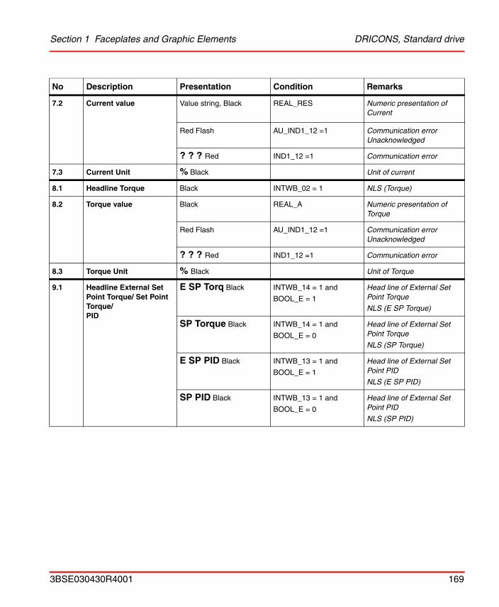
Section 1 Faceplates and Graphic Elements DRICONS, Standard drive
7.2 Current value Value string, Black REAL_RES Numeric presentation of Current
Red Flash AU_IND1_12 =1 Communication error Unacknowledged
? ? ? Red IND1_12 =1 Communication error
7.3 Current Unit % Black Unit of current
8.1 Headline Torque Black INTWB_02 = 1 NLS (Torque)
8.2 Torque value Black REAL_A Numeric presentation of Torque
Red Flash AU_IND1_12 =1 Communication error Unacknowledged
? ? ? Red IND1_12 =1 Communication error
8.3 Torque Unit % Black Unit of Torque
9.1 Headline External Set Point Torque/ Set Point Torque/PID
E SP Torq Black INTWB_14 = 1 and
BOOL_E = 1
Head line of External Set Point Torque
NLS (E SP Torque)
SP Torque Black INTWB_14 = 1 and
BOOL_E = 0
Head line of External Set Point Torque
NLS (SP Torque)
E SP PID Black INTWB_13 = 1 and
BOOL_E = 1
Head line of External Set Point PID
NLS (E SP PID)
SP PID Black INTWB_13 = 1 and
BOOL_E = 0
Head line of External Set Point PID
NLS (SP PID)
No Description Presentation Condition Remarks
3BSE030430R4001 169
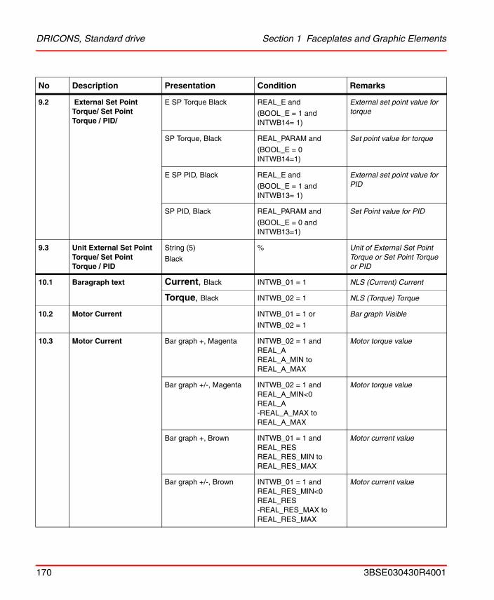
DRICONS, Standard drive Section 1 Faceplates and Graphic Elements
9.2 External Set Point Torque/ Set Point Torque / PID/
E SP Torque Black REAL_E and
(BOOL_E = 1 and INTWB14= 1)
External set point value for torque
SP Torque, Black REAL_PARAM and
(BOOL_E = 0 INTWB14=1)
Set point value for torque
E SP PID, Black REAL_E and
(BOOL_E = 1 and INTWB13= 1)
External set point value for PID
SP PID, Black REAL_PARAM and
(BOOL_E = 0 and INTWB13=1)
Set Point value for PID
9.3 Unit External Set Point Torque/ Set Point Torque / PID
String (5)
Black
% Unit of External Set Point Torque or Set Point Torque or PID
10.1 Baragraph text Current, Black INTWB_01 = 1 NLS (Current) Current
Torque, Black INTWB_02 = 1 NLS (Torque) Torque
10.2 Motor Current INTWB_01 = 1 or
INTWB_02 = 1
Bar graph Visible
10.3 Motor Current Bar graph +, Magenta INTWB_02 = 1 andREAL_AREAL_A_MIN toREAL_A_MAX
Motor torque value
Bar graph +/-, Magenta INTWB_02 = 1 andREAL_A_MIN<0REAL_A-REAL_A_MAX toREAL_A_MAX
Motor torque value
Bar graph +, Brown INTWB_01 = 1 andREAL_RESREAL_RES_MIN toREAL_RES_MAX
Motor current value
Bar graph +/-, Brown INTWB_01 = 1 andREAL_RES_MIN<0REAL_RES-REAL_RES_MAX toREAL_RES_MAX
Motor current value
No Description Presentation Condition Remarks
170 3BSE030430R4001
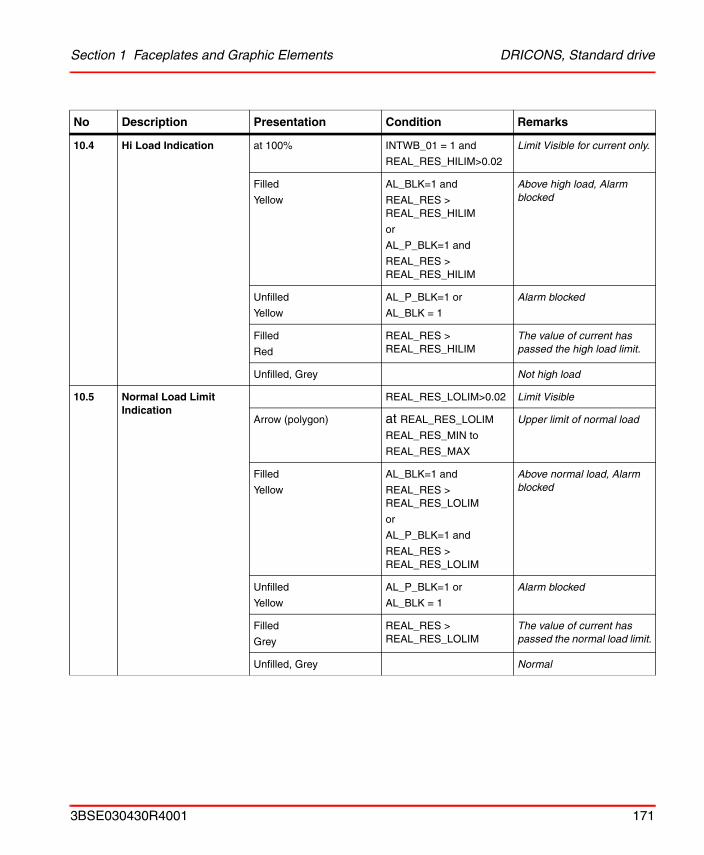
Section 1 Faceplates and Graphic Elements DRICONS, Standard drive
10.4 Hi Load Indication at 100% INTWB_01 = 1 and
REAL_RES_HILIM>0.02
Limit Visible for current only.
Filled
Yellow
AL_BLK=1 and
REAL_RES > REAL_RES_HILIM
or
AL_P_BLK=1 and
REAL_RES > REAL_RES_HILIM
Above high load, Alarm blocked
Unfilled
Yellow
AL_P_BLK=1 or
AL_BLK = 1
Alarm blocked
Filled
Red
REAL_RES > REAL_RES_HILIM
The value of current has passed the high load limit.
Unfilled, Grey Not high load
10.5 Normal Load LimitIndication
REAL_RES_LOLIM>0.02 Limit Visible
Arrow (polygon) at REAL_RES_LOLIM
REAL_RES_MIN to
REAL_RES_MAX
Upper limit of normal load
Filled
Yellow
AL_BLK=1 and
REAL_RES > REAL_RES_LOLIM
or
AL_P_BLK=1 and
REAL_RES > REAL_RES_LOLIM
Above normal load, Alarm blocked
Unfilled
Yellow
AL_P_BLK=1 or
AL_BLK = 1
Alarm blocked
Filled
Grey
REAL_RES > REAL_RES_LOLIM
The value of current has passed the normal load limit.
Unfilled, Grey Normal
No Description Presentation Condition Remarks
3BSE030430R4001 171
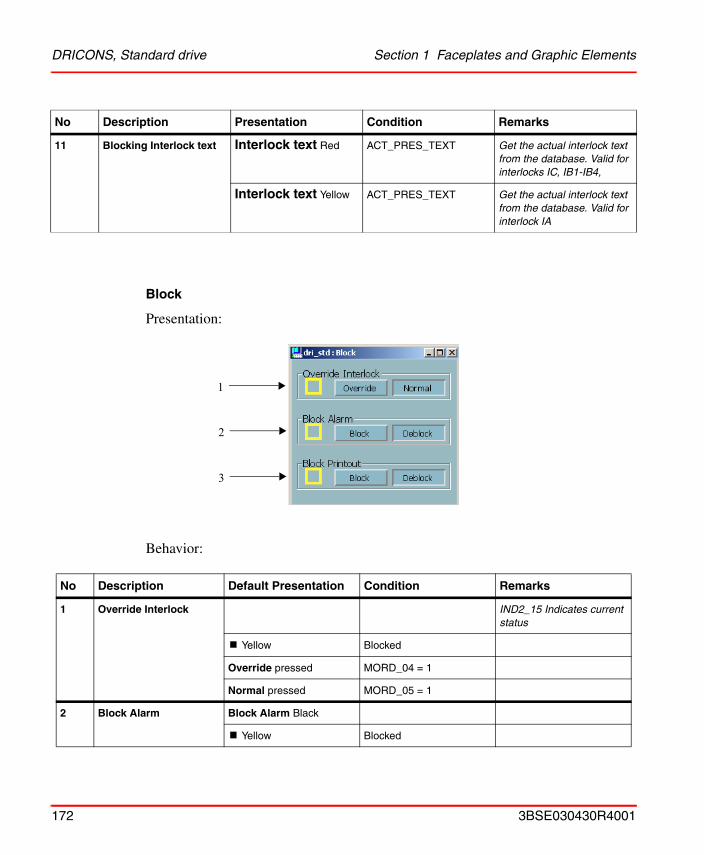
DRICONS, Standard drive Section 1 Faceplates and Graphic Elements
Block
Presentation:
Behavior:
11 Blocking Interlock text Interlock text Red ACT_PRES_TEXT Get the actual interlock text from the database. Valid for interlocks IC, IB1-IB4,
Interlock text Yellow ACT_PRES_TEXT Get the actual interlock text from the database. Valid for interlock IA
No Description Default Presentation Condition Remarks
1 Override Interlock IND2_15 Indicates current status
! Yellow Blocked
Override pressed MORD_04 = 1
Normal pressed MORD_05 = 1
2 Block Alarm Block Alarm Black
! Yellow Blocked
No Description Presentation Condition Remarks
1
2
3
172 3BSE030430R4001
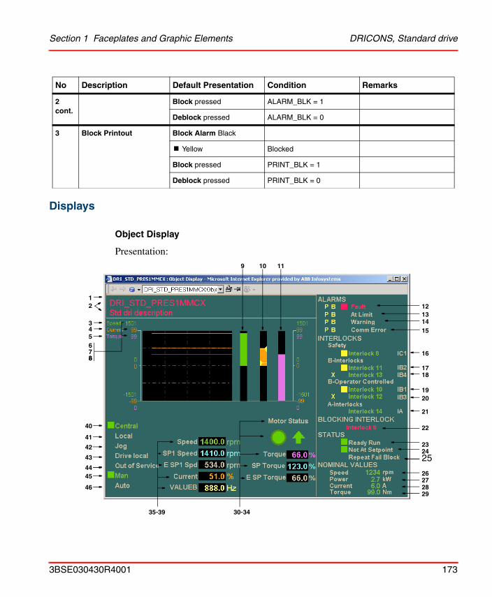
Section 1 Faceplates and Graphic Elements DRICONS, Standard drive
Displays
Object Display
Presentation:
2 cont.
Block pressed ALARM_BLK = 1
Deblock pressed ALARM_BLK = 0
3 Block Printout Block Alarm Black
! Yellow Blocked
Block pressed PRINT_BLK = 1
Deblock pressed PRINT_BLK = 0
No Description Default Presentation Condition Remarks
10
121314
26272829
34
9 11
16
1718
21
20
24
30-34
15
22
25
23
45
42
40
41
35-39
1
65
78
19
2
8
44
46
43
3BSE030430R4001 173
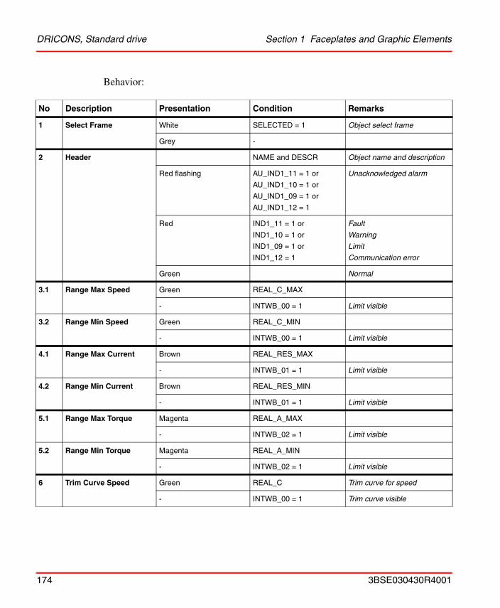
DRICONS, Standard drive Section 1 Faceplates and Graphic Elements
Behavior:
No Description Presentation Condition Remarks
1 Select Frame White SELECTED = 1 Object select frame
Grey -
2 Header NAME and DESCR Object name and description
Red flashing AU_IND1_11 = 1 or
AU_IND1_10 = 1 or
AU_IND1_09 = 1 or
AU_IND1_12 = 1
Unacknowledged alarm
Red IND1_11 = 1 or
IND1_10 = 1 or
IND1_09 = 1 or
IND1_12 = 1
Fault
Warning
Limit
Communication error
Green Normal
3.1 Range Max Speed Green REAL_C_MAX
- INTWB_00 = 1 Limit visible
3.2 Range Min Speed Green REAL_C_MIN
- INTWB_00 = 1 Limit visible
4.1 Range Max Current Brown REAL_RES_MAX
- INTWB_01 = 1 Limit visible
4.2 Range Min Current Brown REAL_RES_MIN
- INTWB_01 = 1 Limit visible
5.1 Range Max Torque Magenta REAL_A_MAX
- INTWB_02 = 1 Limit visible
5.2 Range Min Torque Magenta REAL_A_MIN
- INTWB_02 = 1 Limit visible
6 Trim Curve Speed Green REAL_C Trim curve for speed
- INTWB_00 = 1 Trim curve visible
174 3BSE030430R4001
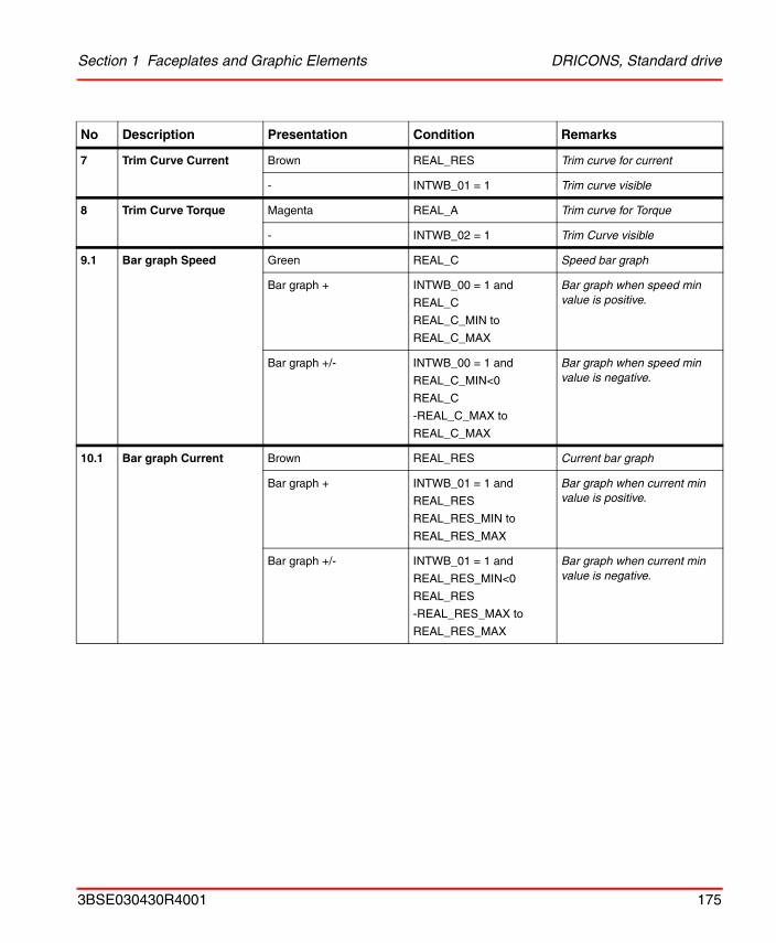
Section 1 Faceplates and Graphic Elements DRICONS, Standard drive
7 Trim Curve Current Brown REAL_RES Trim curve for current
- INTWB_01 = 1 Trim curve visible
8 Trim Curve Torque Magenta REAL_A Trim curve for Torque
- INTWB_02 = 1 Trim Curve visible
9.1 Bar graph Speed Green REAL_C Speed bar graph
Bar graph + INTWB_00 = 1 and
REAL_C
REAL_C_MIN to
REAL_C_MAX
Bar graph when speed min value is positive.
Bar graph +/- INTWB_00 = 1 and
REAL_C_MIN<0
REAL_C
-REAL_C_MAX to
REAL_C_MAX
Bar graph when speed min value is negative.
10.1 Bar graph Current Brown REAL_RES Current bar graph
Bar graph + INTWB_01 = 1 and
REAL_RES
REAL_RES_MIN to
REAL_RES_MAX
Bar graph when current min value is positive.
Bar graph +/- INTWB_01 = 1 and
REAL_RES_MIN<0
REAL_RES
-REAL_RES_MAX to
REAL_RES_MAX
Bar graph when current min value is negative.
No Description Presentation Condition Remarks
3BSE030430R4001 175
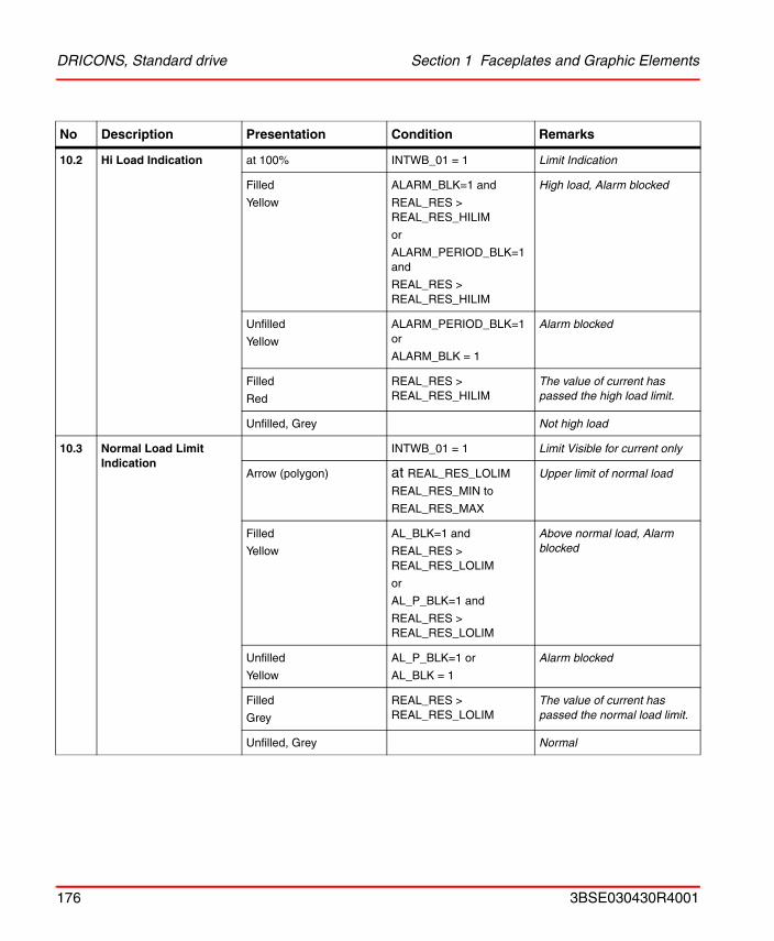
DRICONS, Standard drive Section 1 Faceplates and Graphic Elements
10.2 Hi Load Indication at 100% INTWB_01 = 1 Limit Indication
Filled
Yellow
ALARM_BLK=1 and
REAL_RES > REAL_RES_HILIM
or
ALARM_PERIOD_BLK=1 and
REAL_RES > REAL_RES_HILIM
High load, Alarm blocked
Unfilled
Yellow
ALARM_PERIOD_BLK=1 or
ALARM_BLK = 1
Alarm blocked
Filled
Red
REAL_RES > REAL_RES_HILIM
The value of current has passed the high load limit.
Unfilled, Grey Not high load
10.3 Normal Load Limit Indication
INTWB_01 = 1 Limit Visible for current only
Arrow (polygon) at REAL_RES_LOLIM
REAL_RES_MIN to
REAL_RES_MAX
Upper limit of normal load
Filled
Yellow
AL_BLK=1 and
REAL_RES > REAL_RES_LOLIM
or
AL_P_BLK=1 and
REAL_RES > REAL_RES_LOLIM
Above normal load, Alarm blocked
Unfilled
Yellow
AL_P_BLK=1 or
AL_BLK = 1
Alarm blocked
Filled
Grey
REAL_RES > REAL_RES_LOLIM
The value of current has passed the normal load limit.
Unfilled, Grey Normal
No Description Presentation Condition Remarks
176 3BSE030430R4001
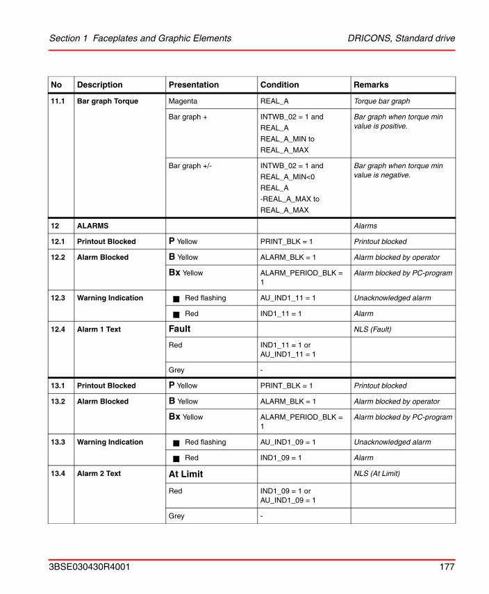
Section 1 Faceplates and Graphic Elements DRICONS, Standard drive
11.1 Bar graph Torque Magenta REAL_A Torque bar graph
Bar graph + INTWB_02 = 1 and
REAL_A
REAL_A_MIN to
REAL_A_MAX
Bar graph when torque min value is positive.
Bar graph +/- INTWB_02 = 1 and
REAL_A_MIN<0
REAL_A
-REAL_A_MAX to
REAL_A_MAX
Bar graph when torque min value is negative.
12 ALARMS Alarms
12.1 Printout Blocked P Yellow PRINT_BLK = 1 Printout blocked
12.2 Alarm Blocked B Yellow ALARM_BLK = 1 Alarm blocked by operator
Bx Yellow ALARM_PERIOD_BLK = 1
Alarm blocked by PC-program
12.3 Warning Indication Red flashing AU_IND1_11 = 1 Unacknowledged alarm
Red IND1_11 = 1 Alarm
12.4 Alarm 1 Text Fault NLS (Fault)
Red IND1_11 = 1 or AU_IND1_11 = 1
Grey -
13.1 Printout Blocked P Yellow PRINT_BLK = 1 Printout blocked
13.2 Alarm Blocked B Yellow ALARM_BLK = 1 Alarm blocked by operator
Bx Yellow ALARM_PERIOD_BLK = 1
Alarm blocked by PC-program
13.3 Warning Indication Red flashing AU_IND1_09 = 1 Unacknowledged alarm
Red IND1_09 = 1 Alarm
13.4 Alarm 2 Text At Limit NLS (At Limit)
Red IND1_09 = 1 or AU_IND1_09 = 1
Grey -
No Description Presentation Condition Remarks
3BSE030430R4001 177
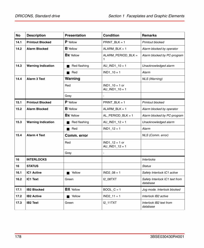
DRICONS, Standard drive Section 1 Faceplates and Graphic Elements
14.1 Printout Blocked P Yellow PRINT_BLK = 1 Printout blocked
14.2 Alarm Blocked B Yellow ALARM_BLK = 1 Alarm blocked by operator
Bx Yellow ALARM_PERIOD_BLK = 1
Alarm blocked by PC-program
14.3 Warning Indication Red flashing AU_IND1_10 = 1 Unacknowledged alarm
Red IND1_10 = 1 Alarm
14.4 Alarm 3 Text Warning NLS (Warning)
Red IND1_10 = 1 or AU_IND1_10 = 1
Grey -
15.1 Printout Blocked P Yellow PRINT_BLK = 1 Printout blocked
15.2 Alarm Blocked B Yellow ALARM_BLK = 1 Alarm blocked by operator
Bx Yellow AL_PERIOD_BLK = 1 Alarm blocked by PC-program
15.3 Warning Indication Red flashing AU_IND1_12 = 1 Unacknowledged alarm
Red IND1_12 = 1 Alarm
15.4 Alarm 4 Text Comm. error NLS (Comm. error)
Red IND1_12 = 1 or AU_IND1_12 = 1
Grey -
16 INTERLOCKS Interlocks
16 STATUS Status
16.1 IC1 Active Yellow IND2_08 = 1 Safety Interlock IC1 active
16.2 IC1 Text Green I2_08TXT Safety Interlock IC1 text from database
17.1 IB2 Blocked BX Yellow BOOL_C = 1 Jog mode. Interlock blocked
17.2 IB2 Active Yellow IND2_11 = 1 Interlock IB2 active
17.3 IB2 Text Green I2_11TXT Interlock IB2 text from database
No Description Presentation Condition Remarks
178 3BSE030430R4001
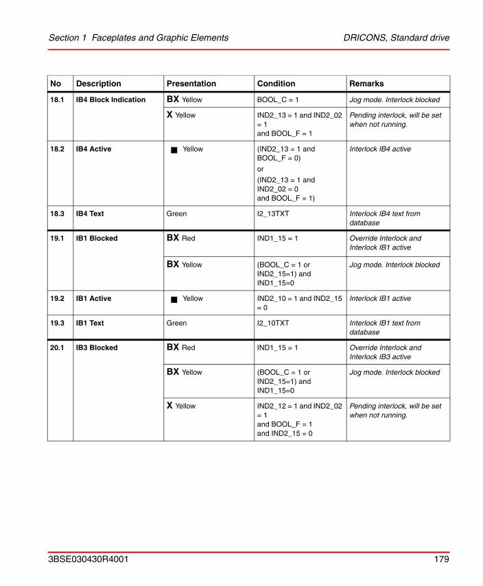
Section 1 Faceplates and Graphic Elements DRICONS, Standard drive
18.1 IB4 Block Indication BX Yellow BOOL_C = 1 Jog mode. Interlock blocked
X Yellow IND2_13 = 1 and IND2_02 = 1and BOOL_F = 1
Pending interlock, will be set when not running.
18.2 IB4 Active Yellow (IND2_13 = 1 and BOOL_F = 0)
or
(IND2_13 = 1 and IND2_02 = 0 and BOOL_F = 1)
Interlock IB4 active
18.3 IB4 Text Green I2_13TXT Interlock IB4 text from database
19.1 IB1 Blocked BX Red IND1_15 = 1 Override Interlock and Interlock IB1 active
BX Yellow (BOOL_C = 1 or IND2_15=1) and IND1_15=0
Jog mode. Interlock blocked
19.2 IB1 Active Yellow IND2_10 = 1 and IND2_15 = 0
Interlock IB1 active
19.3 IB1 Text Green I2_10TXT Interlock IB1 text from database
20.1 IB3 Blocked BX Red IND1_15 = 1 Override Interlock and Interlock IB3 active
BX Yellow (BOOL_C = 1 or IND2_15=1) and IND1_15=0
Jog mode. Interlock blocked
X Yellow IND2_12 = 1 and IND2_02 = 1and BOOL_F = 1and IND2_15 = 0
Pending interlock, will be set when not running.
No Description Presentation Condition Remarks
3BSE030430R4001 179
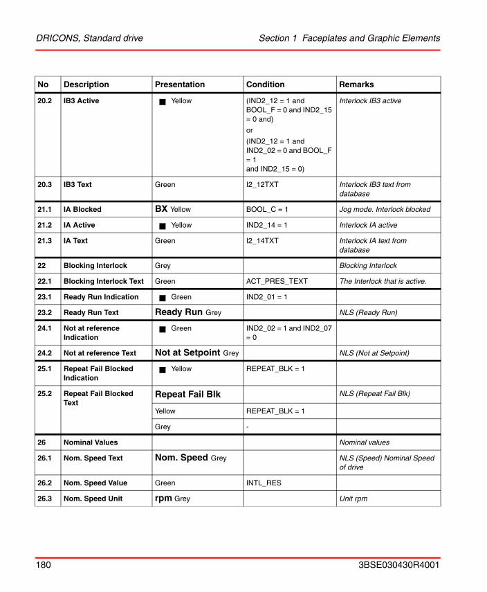
DRICONS, Standard drive Section 1 Faceplates and Graphic Elements
20.2 IB3 Active Yellow (IND2_12 = 1 and BOOL_F = 0 and IND2_15 = 0 and)
or
(IND2_12 = 1 and IND2_02 = 0 and BOOL_F = 1and IND2_15 = 0)
Interlock IB3 active
20.3 IB3 Text Green I2_12TXT Interlock IB3 text from database
21.1 IA Blocked BX Yellow BOOL_C = 1 Jog mode. Interlock blocked
21.2 IA Active Yellow IND2_14 = 1 Interlock IA active
21.3 IA Text Green I2_14TXT Interlock IA text from database
22 Blocking Interlock Grey Blocking Interlock
22.1 Blocking Interlock Text Green ACT_PRES_TEXT The Interlock that is active.
23.1 Ready Run Indication Green IND2_01 = 1
23.2 Ready Run Text Ready Run Grey NLS (Ready Run)
24.1 Not at reference Indication
Green IND2_02 = 1 and IND2_07 = 0
24.2 Not at reference Text Not at Setpoint Grey NLS (Not at Setpoint)
25.1 Repeat Fail Blocked Indication
Yellow REPEAT_BLK = 1
25.2 Repeat Fail Blocked Text
Repeat Fail Blk NLS (Repeat Fail Blk)
Yellow REPEAT_BLK = 1
Grey -
26 Nominal Values Nominal values
26.1 Nom. Speed Text Nom. Speed Grey NLS (Speed) Nominal Speed of drive
26.2 Nom. Speed Value Green INTL_RES
26.3 Nom. Speed Unit rpm Grey Unit rpm
No Description Presentation Condition Remarks
180 3BSE030430R4001
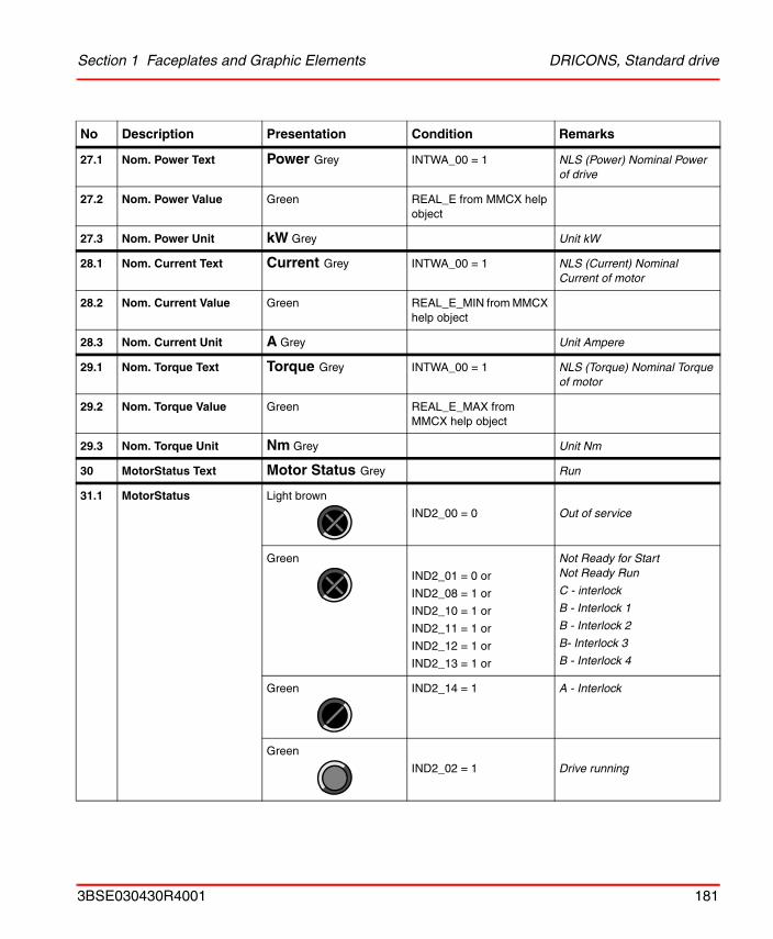
Section 1 Faceplates and Graphic Elements DRICONS, Standard drive
27.1 Nom. Power Text Power Grey INTWA_00 = 1 NLS (Power) Nominal Power of drive
27.2 Nom. Power Value Green REAL_E from MMCX help object
27.3 Nom. Power Unit kW Grey Unit kW
28.1 Nom. Current Text Current Grey INTWA_00 = 1 NLS (Current) Nominal Current of motor
28.2 Nom. Current Value Green REAL_E_MIN from MMCX help object
28.3 Nom. Current Unit A Grey Unit Ampere
29.1 Nom. Torque Text Torque Grey INTWA_00 = 1 NLS (Torque) Nominal Torque of motor
29.2 Nom. Torque Value Green REAL_E_MAX from MMCX help object
29.3 Nom. Torque Unit Nm Grey Unit Nm
30 MotorStatus Text Motor Status Grey Run
31.1 MotorStatus Light brown
IND2_00 = 0 Out of service
Green
IND2_01 = 0 or
IND2_08 = 1 or
IND2_10 = 1 or
IND2_11 = 1 or
IND2_12 = 1 or
IND2_13 = 1 or
Not Ready for StartNot Ready Run
C - interlock
B - Interlock 1
B - Interlock 2
B- Interlock 3
B - Interlock 4
Green IND2_14 = 1 A - Interlock
Green
IND2_02 = 1 Drive running
No Description Presentation Condition Remarks
3BSE030430R4001 181
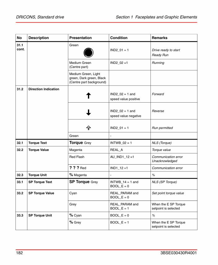
DRICONS, Standard drive Section 1 Faceplates and Graphic Elements
31.1 cont.
Green
IND2_01 = 1 Drive ready to start
Ready Run
Medium Green(Centre part)
IND2_02 =1 Running
Medium Green, Light green, Dark green, Black(Centre part background)
31.2 Direction Indication
IND2_02 = 1 and
speed value positive
Forward
IND2_02 = 1 and
speed value negative
Reverse
IND2_01 = 1 Run permitted
Green -
32.1 Torque Text Torque Grey INTWB_02 = 1 NLS (Torque)
32.2 Torque Value Magenta REAL_A Torque value
Red Flash AU_IND1_12 =1 Communication error Unacknowledged
? ? ? Red IND1_12 =1 Communication error
32.3 Torque Unit % Magenta - %
33.1 SP Torque Text SP Torque Grey INTWB_14 = 1 and BOOL_E = 0
NLS (SP Torque)
33.2 SP Torque Value Cyan REAL_PARAM and BOOL_E = 0
Set point torque value
Grey REAL_PARAM and BOOL_E = 1
When the E SP Torque setpoint is selected
33.3 SP Torque Unit % Cyan BOOL_E = 0 %
% Grey BOOL_E = 1 When the E SP Torque setpoint is selected
No Description Presentation Condition Remarks
182 3BSE030430R4001
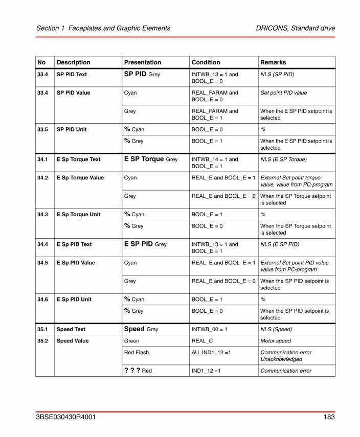
Section 1 Faceplates and Graphic Elements DRICONS, Standard drive
33.4 SP PID Text SP PID Grey INTWB_13 = 1 and BOOL_E = 0
NLS (SP PID)
33.4 SP PID Value Cyan REAL_PARAM and BOOL_E = 0
Set point PID value
Grey REAL_PARAM and BOOL_E = 1
When the E SP PID setpoint is selected
33.5 SP PID Unit % Cyan BOOL_E = 0 %
% Grey BOOL_E = 1 When the E SP PID setpoint is selected
34.1 E Sp Torque Text E SP Torque Grey INTWB_14 = 1 and BOOL_E = 1
NLS (E SP Torque)
34.2 E Sp Torque Value Cyan REAL_E and BOOL_E = 1 External Set point torque value, value from PC-program
Grey REAL_E and BOOL_E = 0 When the SP Torque setpoint is selected
34.3 E Sp Torque Unit % Cyan BOOL_E = 1 %
% Grey BOOL_E = 0 When the SP Torque setpoint is selected
34.4 E Sp PID Text E SP PID Grey INTWB_13 = 1 and BOOL_E = 1
NLS (E SP PID)
34.5 E Sp PID Value Cyan REAL_E and BOOL_E = 1 External Set point PID value, value from PC-program
Grey REAL_E and BOOL_E = 0 When the SP PID setpoint is selected
34.6 E Sp PID Unit % Cyan BOOL_E = 1 %
% Grey BOOL_E = 0 When the SP PID setpoint is selected
35.1 Speed Text Speed Grey INTWB_00 = 1 NLS (Speed)
35.2 Speed Value Green REAL_C Motor speed
Red Flash AU_IND1_12 =1 Communication error Unacknowledged
? ? ? Red IND1_12 =1 Communication error
No Description Presentation Condition Remarks
3BSE030430R4001 183
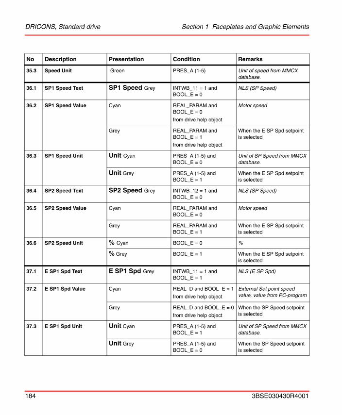
DRICONS, Standard drive Section 1 Faceplates and Graphic Elements
35.3 Speed Unit Green PRES_A (1-5) Unit of speed from MMCX database.
36.1 SP1 Speed Text SP1 Speed Grey INTWB_11 = 1 and BOOL_E = 0
NLS (SP Speed)
36.2 SP1 Speed Value Cyan REAL_PARAM and BOOL_E = 0
from drive help object
Motor speed
Grey REAL_PARAM and BOOL_E = 1
from drive help object
When the E SP Spd setpoint is selected
36.3 SP1 Speed Unit Unit Cyan PRES_A (1-5) and BOOL_E = 0
Unit of SP Speed from MMCX database.
Unit Grey PRES_A (1-5) and BOOL_E = 1
When the E SP Spd setpoint is selected
36.4 SP2 Speed Text SP2 Speed Grey INTWB_12 = 1 and BOOL_E = 0
NLS (SP Speed)
36.5 SP2 Speed Value Cyan REAL_PARAM and BOOL_E = 0
Motor speed
Grey REAL_PARAM and BOOL_E = 1
When the E SP Spd setpoint is selected
36.6 SP2 Speed Unit % Cyan BOOL_E = 0 %
% Grey BOOL_E = 1 When the E SP Spd setpoint is selected
37.1 E SP1 Spd Text E SP1 Spd Grey INTWB_11 = 1 and BOOL_E = 1
NLS (E SP Spd)
37.2 E SP1 Spd Value Cyan REAL_D and BOOL_E = 1
from drive help object
External Set point speed value, value from PC-program
Grey REAL_D and BOOL_E = 0
from drive help object
When the SP Speed setpoint is selected
37.3 E SP1 Spd Unit Unit Cyan PRES_A (1-5) and BOOL_E = 1
Unit of SP Speed from MMCX database.
Unit Grey PRES_A (1-5) and BOOL_E = 0
When the SP Speed setpoint is selected
No Description Presentation Condition Remarks
184 3BSE030430R4001
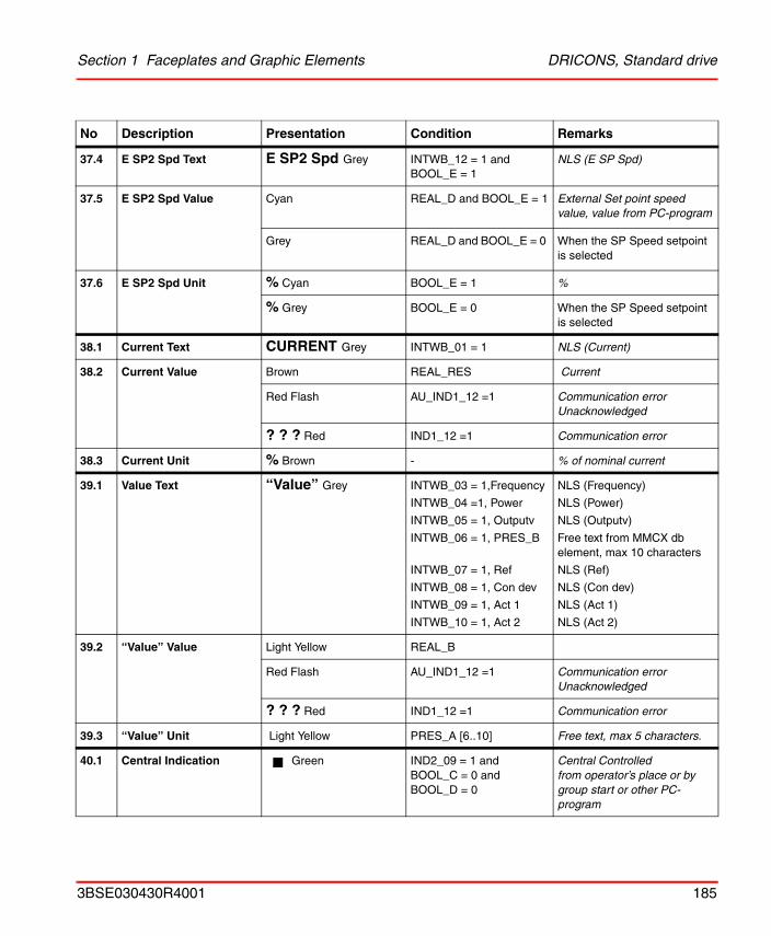
Section 1 Faceplates and Graphic Elements DRICONS, Standard drive
37.4 E SP2 Spd Text E SP2 Spd Grey INTWB_12 = 1 and BOOL_E = 1
NLS (E SP Spd)
37.5 E SP2 Spd Value Cyan REAL_D and BOOL_E = 1 External Set point speed value, value from PC-program
Grey REAL_D and BOOL_E = 0 When the SP Speed setpoint is selected
37.6 E SP2 Spd Unit % Cyan BOOL_E = 1 %
% Grey BOOL_E = 0 When the SP Speed setpoint is selected
38.1 Current Text CURRENT Grey INTWB_01 = 1 NLS (Current)
38.2 Current Value Brown REAL_RES Current
Red Flash AU_IND1_12 =1 Communication error Unacknowledged
? ? ? Red IND1_12 =1 Communication error
38.3 Current Unit % Brown - % of nominal current
39.1 Value Text “Value” Grey INTWB_03 = 1,Frequency
INTWB_04 =1, Power
INTWB_05 = 1, Outputv
INTWB_06 = 1, PRES_B
INTWB_07 = 1, Ref
INTWB_08 = 1, Con dev
INTWB_09 = 1, Act 1
INTWB_10 = 1, Act 2
NLS (Frequency)
NLS (Power)
NLS (Outputv)
Free text from MMCX db element, max 10 characters
NLS (Ref)
NLS (Con dev)
NLS (Act 1)
NLS (Act 2)
39.2 “Value” Value Light Yellow REAL_B
Red Flash AU_IND1_12 =1 Communication error Unacknowledged
? ? ? Red IND1_12 =1 Communication error
39.3 “Value” Unit Light Yellow PRES_A [6..10] Free text, max 5 characters.
40.1 Central Indication Green IND2_09 = 1 andBOOL_C = 0 andBOOL_D = 0
Central Controlled from operator’s place or by group start or other PC-program
No Description Presentation Condition Remarks
3BSE030430R4001 185
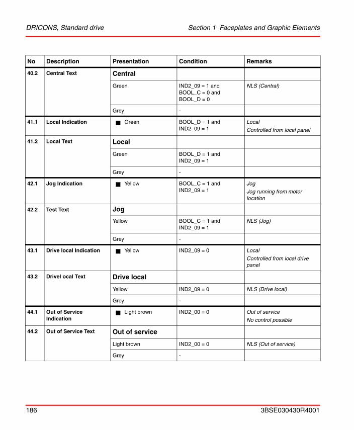
DRICONS, Standard drive Section 1 Faceplates and Graphic Elements
40.2 Central Text Central
Green IND2_09 = 1 andBOOL_C = 0 andBOOL_D = 0
NLS (Central)
Grey -
41.1 Local Indication Green BOOL_D = 1 andIND2_09 = 1
Local
Controlled from local panel
41.2 Local Text Local
Green BOOL_D = 1 andIND2_09 = 1
Grey -
42.1 Jog Indication Yellow BOOL_C = 1 and IND2_09 = 1
Jog
Jog running from motor location
42.2 Test Text Jog
Yellow BOOL_C = 1 and IND2_09 = 1
NLS (Jog)
Grey -
43.1 Drive local Indication Yellow IND2_09 = 0 Local
Controlled from local drive panel
43.2 Drivel ocal Text Drive local
Yellow IND2_09 = 0 NLS (Drive local)
Grey -
44.1 Out of Service Indication
Light brown IND2_00 = 0 Out of service
No control possible
44.2 Out of Service Text Out of service
Light brown IND2_00 = 0 NLS (Out of service)
Grey -
No Description Presentation Condition Remarks
186 3BSE030430R4001
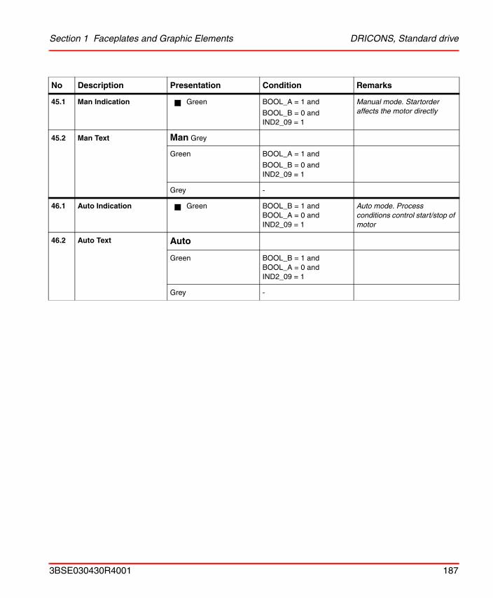
Section 1 Faceplates and Graphic Elements DRICONS, Standard drive
45.1 Man Indication Green BOOL_A = 1 and
BOOL_B = 0 andIND2_09 = 1
Manual mode. Startorder affects the motor directly
45.2 Man Text Man Grey
Green BOOL_A = 1 and
BOOL_B = 0 andIND2_09 = 1
Grey -
46.1 Auto Indication Green BOOL_B = 1 andBOOL_A = 0 andIND2_09 = 1
Auto mode. Process conditions control start/stop of motor
46.2 Auto Text Auto
Green BOOL_B = 1 andBOOL_A = 0 andIND2_09 = 1
Grey -
No Description Presentation Condition Remarks
3BSE030430R4001 187
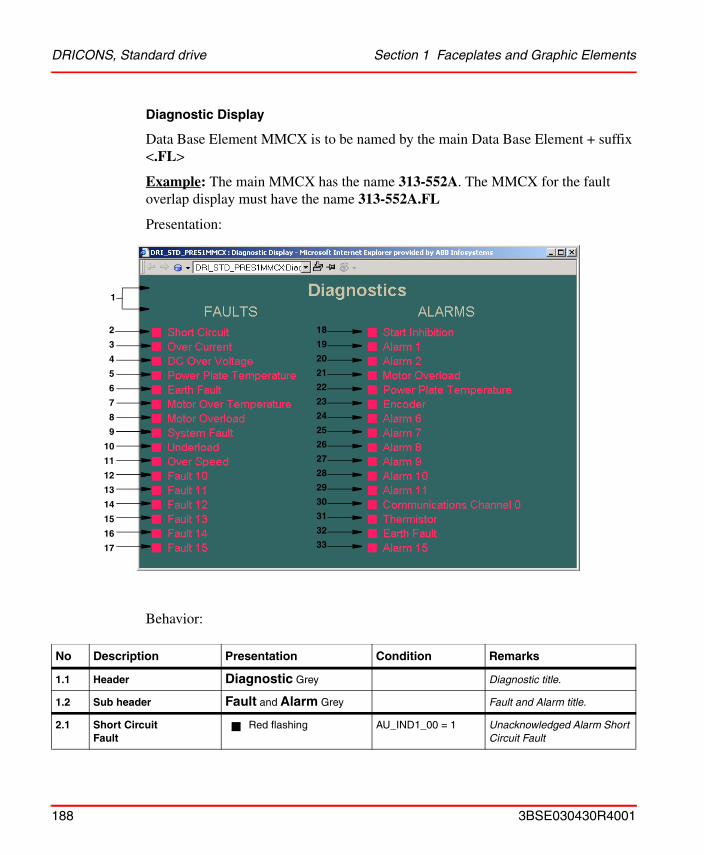
DRICONS, Standard drive Section 1 Faceplates and Graphic Elements
Diagnostic Display
Data Base Element MMCX is to be named by the main Data Base Element + suffix <.FL>
Example: The main MMCX has the name 313-552A. The MMCX for the fault overlap display must have the name 313-552A.FL
Presentation:
Behavior:
No Description Presentation Condition Remarks
1.1 Header Diagnostic Grey Diagnostic title.
1.2 Sub header Fault and Alarm Grey Fault and Alarm title.
2.1 Short Circuit Fault
Red flashing AU_IND1_00 = 1 Unacknowledged Alarm Short Circuit Fault
3
4
5
6
7
8
9
10
11
12
13
14
15
16
19
20
21
22
23
24
25
26
27
28
29
30
31
32
17
1
18
33
2
188 3BSE030430R4001
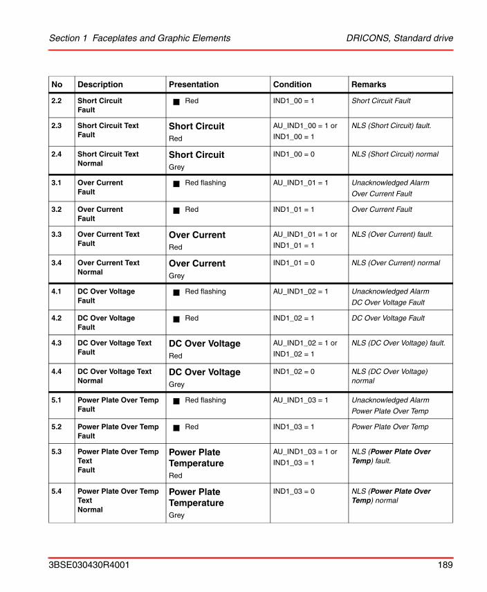
Section 1 Faceplates and Graphic Elements DRICONS, Standard drive
2.2 Short Circuit Fault
Red IND1_00 = 1 Short Circuit Fault
2.3 Short Circuit Text Fault
Short CircuitRed
AU_IND1_00 = 1 or
IND1_00 = 1
NLS (Short Circuit) fault.
2.4 Short Circuit TextNormal
Short CircuitGrey
IND1_00 = 0 NLS (Short Circuit) normal
3.1 Over CurrentFault
Red flashing AU_IND1_01 = 1 Unacknowledged Alarm
Over Current Fault
3.2 Over CurrentFault
Red IND1_01 = 1 Over Current Fault
3.3 Over Current Text Fault
Over CurrentRed
AU_IND1_01 = 1 or
IND1_01 = 1
NLS (Over Current) fault.
3.4 Over Current TextNormal
Over CurrentGrey
IND1_01 = 0 NLS (Over Current) normal
4.1 DC Over VoltageFault
Red flashing AU_IND1_02 = 1 Unacknowledged Alarm
DC Over Voltage Fault
4.2 DC Over VoltageFault
Red IND1_02 = 1 DC Over Voltage Fault
4.3 DC Over Voltage Text Fault
DC Over VoltageRed
AU_IND1_02 = 1 or
IND1_02 = 1
NLS (DC Over Voltage) fault.
4.4 DC Over Voltage TextNormal
DC Over VoltageGrey
IND1_02 = 0 NLS (DC Over Voltage) normal
5.1 Power Plate Over TempFault
Red flashing AU_IND1_03 = 1 Unacknowledged Alarm
Power Plate Over Temp
5.2 Power Plate Over TempFault
Red IND1_03 = 1 Power Plate Over Temp
5.3 Power Plate Over Temp Text Fault
Power Plate TemperatureRed
AU_IND1_03 = 1 or
IND1_03 = 1
NLS (Power Plate Over Temp) fault.
5.4 Power Plate Over Temp TextNormal
Power PlateTemperatureGrey
IND1_03 = 0 NLS (Power Plate Over Temp) normal
No Description Presentation Condition Remarks
3BSE030430R4001 189
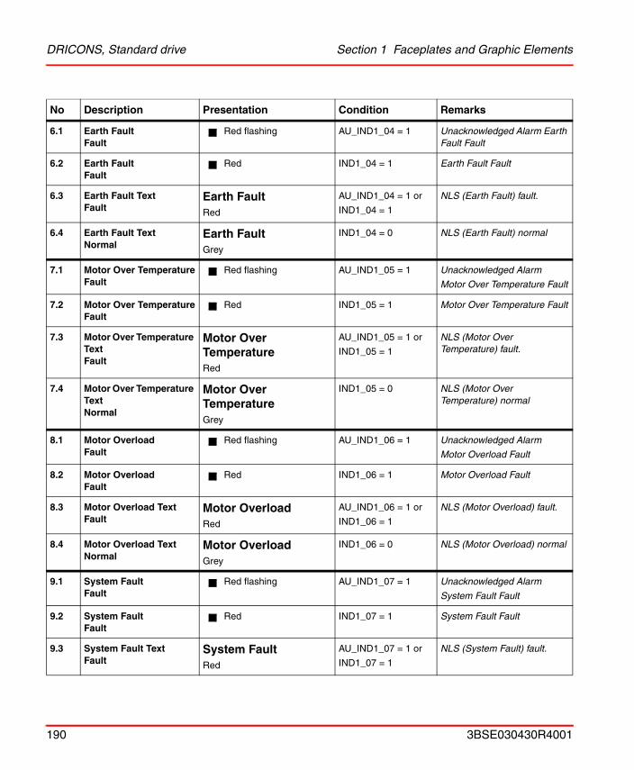
DRICONS, Standard drive Section 1 Faceplates and Graphic Elements
6.1 Earth FaultFault
Red flashing AU_IND1_04 = 1 Unacknowledged Alarm Earth Fault Fault
6.2 Earth FaultFault
Red IND1_04 = 1 Earth Fault Fault
6.3 Earth Fault Text Fault
Earth FaultRed
AU_IND1_04 = 1 or
IND1_04 = 1
NLS (Earth Fault) fault.
6.4 Earth Fault TextNormal
Earth FaultGrey
IND1_04 = 0 NLS (Earth Fault) normal
7.1 Motor Over TemperatureFault
Red flashing AU_IND1_05 = 1 Unacknowledged Alarm
Motor Over Temperature Fault
7.2 Motor Over TemperatureFault
Red IND1_05 = 1 Motor Over Temperature Fault
7.3 Motor Over Temperature Text Fault
Motor Over TemperatureRed
AU_IND1_05 = 1 or
IND1_05 = 1
NLS (Motor Over Temperature) fault.
7.4 Motor Over Temperature TextNormal
Motor Over TemperatureGrey
IND1_05 = 0 NLS (Motor Over Temperature) normal
8.1 Motor OverloadFault
Red flashing AU_IND1_06 = 1 Unacknowledged Alarm
Motor Overload Fault
8.2 Motor OverloadFault
Red IND1_06 = 1 Motor Overload Fault
8.3 Motor Overload Text Fault
Motor OverloadRed
AU_IND1_06 = 1 or
IND1_06 = 1
NLS (Motor Overload) fault.
8.4 Motor Overload TextNormal
Motor OverloadGrey
IND1_06 = 0 NLS (Motor Overload) normal
9.1 System FaultFault
Red flashing AU_IND1_07 = 1 Unacknowledged Alarm
System Fault Fault
9.2 System FaultFault
Red IND1_07 = 1 System Fault Fault
9.3 System Fault Text Fault
System FaultRed
AU_IND1_07 = 1 or
IND1_07 = 1
NLS (System Fault) fault.
No Description Presentation Condition Remarks
190 3BSE030430R4001
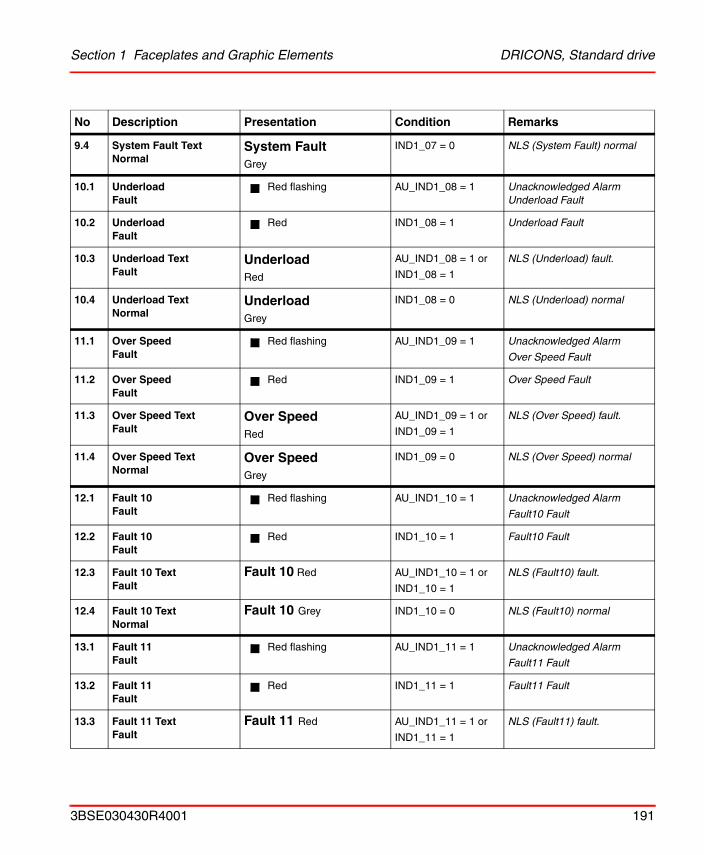
Section 1 Faceplates and Graphic Elements DRICONS, Standard drive
9.4 System Fault TextNormal
System FaultGrey
IND1_07 = 0 NLS (System Fault) normal
10.1 UnderloadFault
Red flashing AU_IND1_08 = 1 Unacknowledged Alarm Underload Fault
10.2 UnderloadFault
Red IND1_08 = 1 Underload Fault
10.3 Underload Text Fault
UnderloadRed
AU_IND1_08 = 1 or
IND1_08 = 1
NLS (Underload) fault.
10.4 Underload TextNormal
UnderloadGrey
IND1_08 = 0 NLS (Underload) normal
11.1 Over SpeedFault
Red flashing AU_IND1_09 = 1 Unacknowledged Alarm
Over Speed Fault
11.2 Over SpeedFault
Red IND1_09 = 1 Over Speed Fault
11.3 Over Speed Text Fault
Over SpeedRed
AU_IND1_09 = 1 or
IND1_09 = 1
NLS (Over Speed) fault.
11.4 Over Speed TextNormal
Over SpeedGrey
IND1_09 = 0 NLS (Over Speed) normal
12.1 Fault 10Fault
Red flashing AU_IND1_10 = 1 Unacknowledged Alarm
Fault10 Fault
12.2 Fault 10Fault
Red IND1_10 = 1 Fault10 Fault
12.3 Fault 10 Text Fault
Fault 10 Red AU_IND1_10 = 1 or
IND1_10 = 1
NLS (Fault10) fault.
12.4 Fault 10 TextNormal
Fault 10 Grey IND1_10 = 0 NLS (Fault10) normal
13.1 Fault 11Fault
Red flashing AU_IND1_11 = 1 Unacknowledged Alarm
Fault11 Fault
13.2 Fault 11Fault
Red IND1_11 = 1 Fault11 Fault
13.3 Fault 11 Text Fault
Fault 11 Red AU_IND1_11 = 1 or
IND1_11 = 1
NLS (Fault11) fault.
No Description Presentation Condition Remarks
3BSE030430R4001 191
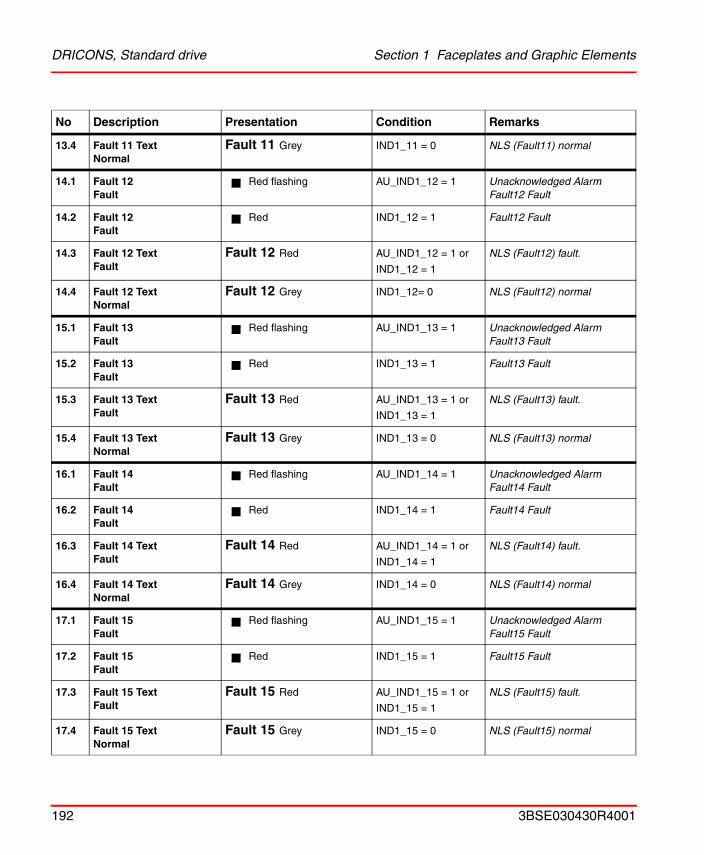
DRICONS, Standard drive Section 1 Faceplates and Graphic Elements
13.4 Fault 11 TextNormal
Fault 11 Grey IND1_11 = 0 NLS (Fault11) normal
14.1 Fault 12Fault
Red flashing AU_IND1_12 = 1 Unacknowledged Alarm Fault12 Fault
14.2 Fault 12Fault
Red IND1_12 = 1 Fault12 Fault
14.3 Fault 12 Text Fault
Fault 12 Red AU_IND1_12 = 1 or
IND1_12 = 1
NLS (Fault12) fault.
14.4 Fault 12 TextNormal
Fault 12 Grey IND1_12= 0 NLS (Fault12) normal
15.1 Fault 13Fault
Red flashing AU_IND1_13 = 1 Unacknowledged Alarm Fault13 Fault
15.2 Fault 13Fault
Red IND1_13 = 1 Fault13 Fault
15.3 Fault 13 Text Fault
Fault 13 Red AU_IND1_13 = 1 or
IND1_13 = 1
NLS (Fault13) fault.
15.4 Fault 13 TextNormal
Fault 13 Grey IND1_13 = 0 NLS (Fault13) normal
16.1 Fault 14Fault
Red flashing AU_IND1_14 = 1 Unacknowledged Alarm Fault14 Fault
16.2 Fault 14Fault
Red IND1_14 = 1 Fault14 Fault
16.3 Fault 14 Text Fault
Fault 14 Red AU_IND1_14 = 1 or
IND1_14 = 1
NLS (Fault14) fault.
16.4 Fault 14 TextNormal
Fault 14 Grey IND1_14 = 0 NLS (Fault14) normal
17.1 Fault 15Fault
Red flashing AU_IND1_15 = 1 Unacknowledged Alarm Fault15 Fault
17.2 Fault 15Fault
Red IND1_15 = 1 Fault15 Fault
17.3 Fault 15 Text Fault
Fault 15 Red AU_IND1_15 = 1 or
IND1_15 = 1
NLS (Fault15) fault.
17.4 Fault 15 TextNormal
Fault 15 Grey IND1_15 = 0 NLS (Fault15) normal
No Description Presentation Condition Remarks
192 3BSE030430R4001
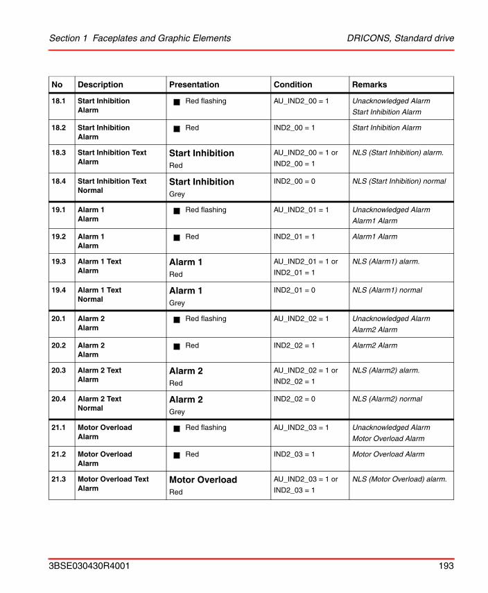
Section 1 Faceplates and Graphic Elements DRICONS, Standard drive
18.1 Start InhibitionAlarm
Red flashing AU_IND2_00 = 1 Unacknowledged Alarm
Start Inhibition Alarm
18.2 Start InhibitionAlarm
Red IND2_00 = 1 Start Inhibition Alarm
18.3 Start Inhibition Text Alarm
Start InhibitionRed
AU_IND2_00 = 1 or
IND2_00 = 1
NLS (Start Inhibition) alarm.
18.4 Start Inhibition TextNormal
Start InhibitionGrey
IND2_00 = 0 NLS (Start Inhibition) normal
19.1 Alarm 1Alarm
Red flashing AU_IND2_01 = 1 Unacknowledged Alarm
Alarm1 Alarm
19.2 Alarm 1Alarm
Red IND2_01 = 1 Alarm1 Alarm
19.3 Alarm 1 Text Alarm
Alarm 1Red
AU_IND2_01 = 1 or
IND2_01 = 1
NLS (Alarm1) alarm.
19.4 Alarm 1 TextNormal
Alarm 1Grey
IND2_01 = 0 NLS (Alarm1) normal
20.1 Alarm 2Alarm
Red flashing AU_IND2_02 = 1 Unacknowledged Alarm
Alarm2 Alarm
20.2 Alarm 2Alarm
Red IND2_02 = 1 Alarm2 Alarm
20.3 Alarm 2 Text Alarm
Alarm 2Red
AU_IND2_02 = 1 or
IND2_02 = 1
NLS (Alarm2) alarm.
20.4 Alarm 2 TextNormal
Alarm 2Grey
IND2_02 = 0 NLS (Alarm2) normal
21.1 Motor OverloadAlarm
Red flashing AU_IND2_03 = 1 Unacknowledged Alarm
Motor Overload Alarm
21.2 Motor OverloadAlarm
Red IND2_03 = 1 Motor Overload Alarm
21.3 Motor Overload Text Alarm
Motor OverloadRed
AU_IND2_03 = 1 or
IND2_03 = 1
NLS (Motor Overload) alarm.
No Description Presentation Condition Remarks
3BSE030430R4001 193
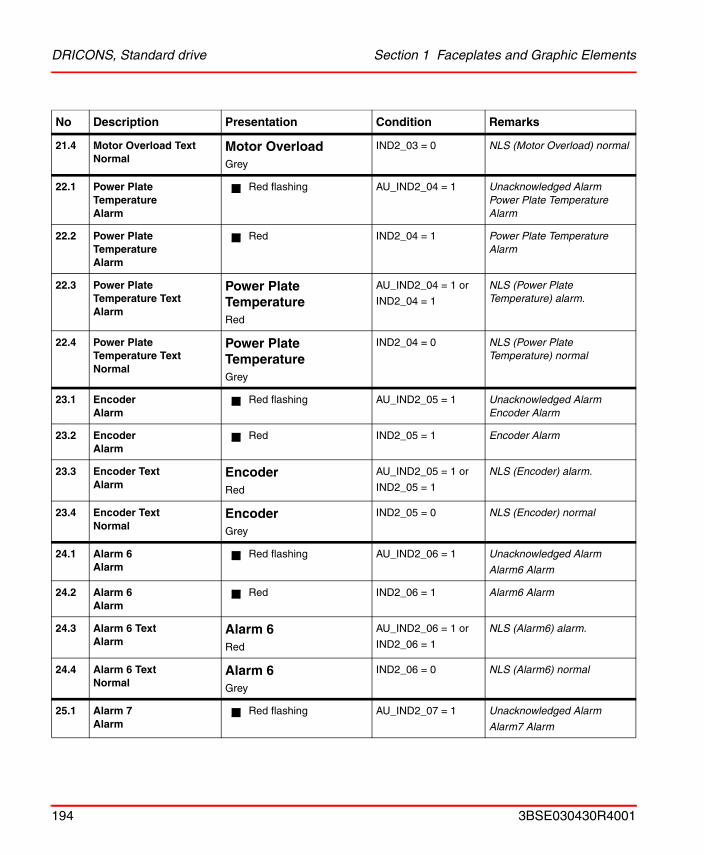
DRICONS, Standard drive Section 1 Faceplates and Graphic Elements
21.4 Motor Overload TextNormal
Motor OverloadGrey
IND2_03 = 0 NLS (Motor Overload) normal
22.1 Power Plate TemperatureAlarm
Red flashing AU_IND2_04 = 1 Unacknowledged Alarm Power Plate Temperature Alarm
22.2 Power Plate TemperatureAlarm
Red IND2_04 = 1 Power Plate Temperature Alarm
22.3 Power Plate Temperature Text Alarm
Power Plate TemperatureRed
AU_IND2_04 = 1 or
IND2_04 = 1
NLS (Power Plate Temperature) alarm.
22.4 Power Plate Temperature TextNormal
Power Plate TemperatureGrey
IND2_04 = 0 NLS (Power Plate Temperature) normal
23.1 EncoderAlarm
Red flashing AU_IND2_05 = 1 Unacknowledged Alarm Encoder Alarm
23.2 EncoderAlarm
Red IND2_05 = 1 Encoder Alarm
23.3 Encoder Text Alarm
EncoderRed
AU_IND2_05 = 1 or
IND2_05 = 1
NLS (Encoder) alarm.
23.4 Encoder TextNormal
EncoderGrey
IND2_05 = 0 NLS (Encoder) normal
24.1 Alarm 6Alarm
Red flashing AU_IND2_06 = 1 Unacknowledged Alarm
Alarm6 Alarm
24.2 Alarm 6Alarm
Red IND2_06 = 1 Alarm6 Alarm
24.3 Alarm 6 Text Alarm
Alarm 6Red
AU_IND2_06 = 1 or
IND2_06 = 1
NLS (Alarm6) alarm.
24.4 Alarm 6 TextNormal
Alarm 6Grey
IND2_06 = 0 NLS (Alarm6) normal
25.1 Alarm 7Alarm
Red flashing AU_IND2_07 = 1 Unacknowledged Alarm
Alarm7 Alarm
No Description Presentation Condition Remarks
194 3BSE030430R4001
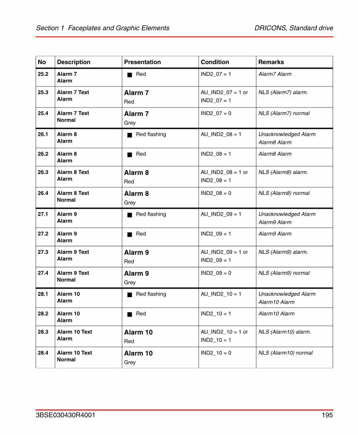
Section 1 Faceplates and Graphic Elements DRICONS, Standard drive
25.2 Alarm 7Alarm
Red IND2_07 = 1 Alarm7 Alarm
25.3 Alarm 7 Text Alarm
Alarm 7Red
AU_IND2_07 = 1 or
IND2_07 = 1
NLS (Alarm7) alarm.
25.4 Alarm 7 TextNormal
Alarm 7Grey
IND2_07 = 0 NLS (Alarm7) normal
26.1 Alarm 8Alarm
Red flashing AU_IND2_08 = 1 Unacknowledged Alarm
Alarm8 Alarm
26.2 Alarm 8Alarm
Red IND2_08 = 1 Alarm8 Alarm
26.3 Alarm 8 Text Alarm
Alarm 8Red
AU_IND2_08 = 1 or
IND2_08 = 1
NLS (Alarm8) alarm.
26.4 Alarm 8 TextNormal
Alarm 8Grey
IND2_08 = 0 NLS (Alarm8) normal
27.1 Alarm 9Alarm
Red flashing AU_IND2_09 = 1 Unacknowledged Alarm
Alarm9 Alarm
27.2 Alarm 9Alarm
Red IND2_09 = 1 Alarm9 Alarm
27.3 Alarm 9 Text Alarm
Alarm 9Red
AU_IND2_09 = 1 or
IND2_09 = 1
NLS (Alarm9) alarm.
27.4 Alarm 9 TextNormal
Alarm 9Grey
IND2_09 = 0 NLS (Alarm9) normal
28.1 Alarm 10Alarm
Red flashing AU_IND2_10 = 1 Unacknowledged Alarm
Alarm10 Alarm
28.2 Alarm 10Alarm
Red IND2_10 = 1 Alarm10 Alarm
28.3 Alarm 10 Text Alarm
Alarm 10Red
AU_IND2_10 = 1 or
IND2_10 = 1
NLS (Alarm10) alarm.
28.4 Alarm 10 TextNormal
Alarm 10Grey
IND2_10 = 0 NLS (Alarm10) normal
No Description Presentation Condition Remarks
3BSE030430R4001 195
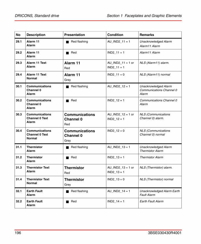
DRICONS, Standard drive Section 1 Faceplates and Graphic Elements
29.1 Alarm 11Alarm
Red flashing AU_IND2_11 = 1 Unacknowledged Alarm
Alarm11 Alarm
29.2 Alarm 11Alarm
Red IND2_11 = 1 Alarm11 Alarm
29.3 Alarm 11 Text Alarm
Alarm 11Red
AU_IND2_11 = 1 or
IND2_11 = 1
NLS (Alarm11) alarm.
29.4 Alarm 11 TextNormal
Alarm 11Grey
IND2_11 = 0 NLS (Alarm11) normal
30.1 Communications Channel 0Alarm
Red flashing AU_IND2_12 = 1 Unacknowledged Alarm Communications Channel 0 Alarm
30.2 Communications Channel 0Alarm
Red IND2_12 = 1 Communications Channel 0 Alarm
30.3 Communications Channel 0 Text Alarm
Communications Channel 0Red
AU_IND2_12 = 1 or
IND2_12 = 1
NLS (Communications Channel 0) alarm.
30.4 Communications Channel 0 TextNormal
Communications Channel 0Grey
IND2_12 = 0 NLS (Communications Channel 0) normal
31.1 ThermistorAlarm
Red flashing AU_IND2_13 = 1 Unacknowledged Alarm Thermistor Alarm
31.2 ThermistorAlarm
Red IND2_13 = 1 Thermistor Alarm
31.3 Thermistor Text Alarm
ThermistorRed
AU_IND2_13 = 1 or
IND2_13 = 1
NLS (Thermistor) alarm.
31.4 Thermistor TextNormal
ThermistorGrey
IND2_13 = 0 NLS (Thermistor) normal
32.1 Earth FaultAlarm
Red flashing AU_IND2_14 = 1 Unacknowledged Alarm Earth Fault Alarm
32.2 Earth FaultAlarm
Red IND2_14 = 1 Earth Fault Alarm
No Description Presentation Condition Remarks
196 3BSE030430R4001
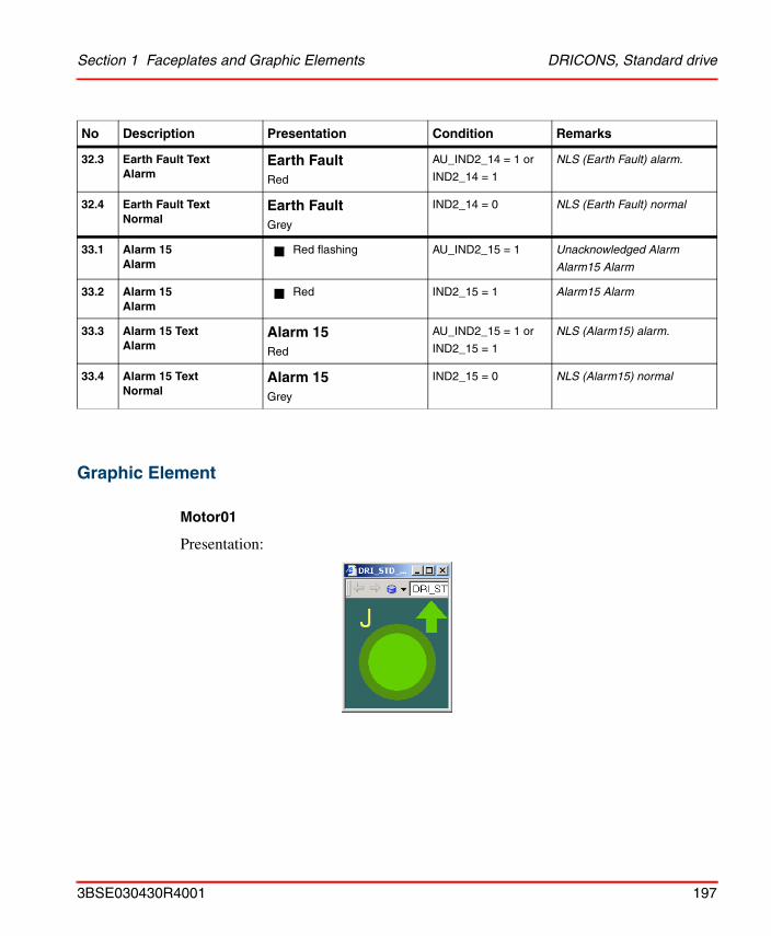
Section 1 Faceplates and Graphic Elements DRICONS, Standard drive
Graphic Element
Motor01
Presentation:
32.3 Earth Fault Text Alarm
Earth FaultRed
AU_IND2_14 = 1 or
IND2_14 = 1
NLS (Earth Fault) alarm.
32.4 Earth Fault TextNormal
Earth FaultGrey
IND2_14 = 0 NLS (Earth Fault) normal
33.1 Alarm 15Alarm
Red flashing AU_IND2_15 = 1 Unacknowledged Alarm
Alarm15 Alarm
33.2 Alarm 15Alarm
Red IND2_15 = 1 Alarm15 Alarm
33.3 Alarm 15 Text Alarm
Alarm 15Red
AU_IND2_15 = 1 or
IND2_15 = 1
NLS (Alarm15) alarm.
33.4 Alarm 15 TextNormal
Alarm 15Grey
IND2_15 = 0 NLS (Alarm15) normal
No Description Presentation Condition Remarks
3BSE030430R4001 197
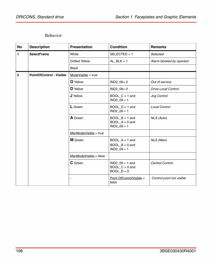
DRICONS, Standard drive Section 1 Faceplates and Graphic Elements
Behavior:
No Description Presentation Condition Remarks
1 SelectFrame White SELECTED = 1 Selected
Dotted Yellow AL_BLK = 1 Alarm blocked by operator
Black -
2 PointOfControl - Visible ModeVisible = true
O Yellow IND2_00= 0 Out of service
D Yellow IND2_09= 0 Drive Local Control
J Yellow BOOL_C = 1 andIND2_09 = 1
Jog Control
L Green BOOL_D = 1 andIND2_09 = 1
Local Control
A Green BOOL_B = 1 andBOOL_A = 0 andIND2_09 = 1
NLS (Auto)
ManModeVisible = true
M Green BOOL_A = 1 and
BOOL_B = 0 andIND2_09 = 1
NLS (Man)
ManModeVisible = false
C Green IND2_09 = 1 andBOOL_C = 0 andBOOL_D = 0
Central Control
- Point OfControlVisible = false
Control point not visible
198 3BSE030430R4001
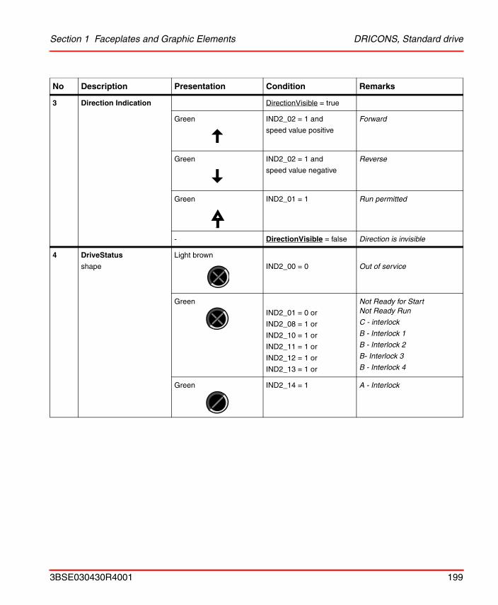
Section 1 Faceplates and Graphic Elements DRICONS, Standard drive
3 Direction Indication DirectionVisible = true
Green IND2_02 = 1 and
speed value positive
Forward
Green IND2_02 = 1 and
speed value negative
Reverse
Green IND2_01 = 1 Run permitted
- DirectionVisible = false Direction is invisible
4 DriveStatus
shape
Light brown
IND2_00 = 0 Out of service
Green
IND2_01 = 0 or
IND2_08 = 1 or
IND2_10 = 1 or
IND2_11 = 1 or
IND2_12 = 1 or
IND2_13 = 1 or
Not Ready for StartNot Ready Run
C - interlock
B - Interlock 1
B - Interlock 2
B- Interlock 3
B - Interlock 4
Green IND2_14 = 1 A - Interlock
No Description Presentation Condition Remarks
3BSE030430R4001 199
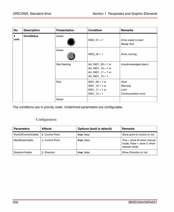
DRICONS, Standard drive Section 1 Faceplates and Graphic Elements
The conditions are in priority order. Underlined parameters are configurable.
Configuration:
4 cont.
DriveStatus Green
IND2_01 = 1 Drive ready to start
Ready Run
Green
IND2_02 = 1 Drive running
Red flashing AU_IND1_09 = 1 or
AU_IND1_10 = 1 or
AU_IND1_11 = 1 or
AU_IND1_12 = 1
Unacknowledged alarm
Red IND1_09 = 1 or
IND1_10 = 1 or
IND1_11 = 1 or
IND1_12 = 1
Fault
Warning
Limit
Communication error
Green -
Parameters Affects Options (bold is default) Remarks
PointOfControlVisible 2. Control Point true, false Show point of control or not.
ManModeVisible 2. Control Point true, false True = show M when manual mode. False = show C when manual mode.
DirectionVisible 3. Direction true, false Show Direction or not.
No Description Presentation Condition Remarks
200 3BSE030430R4001
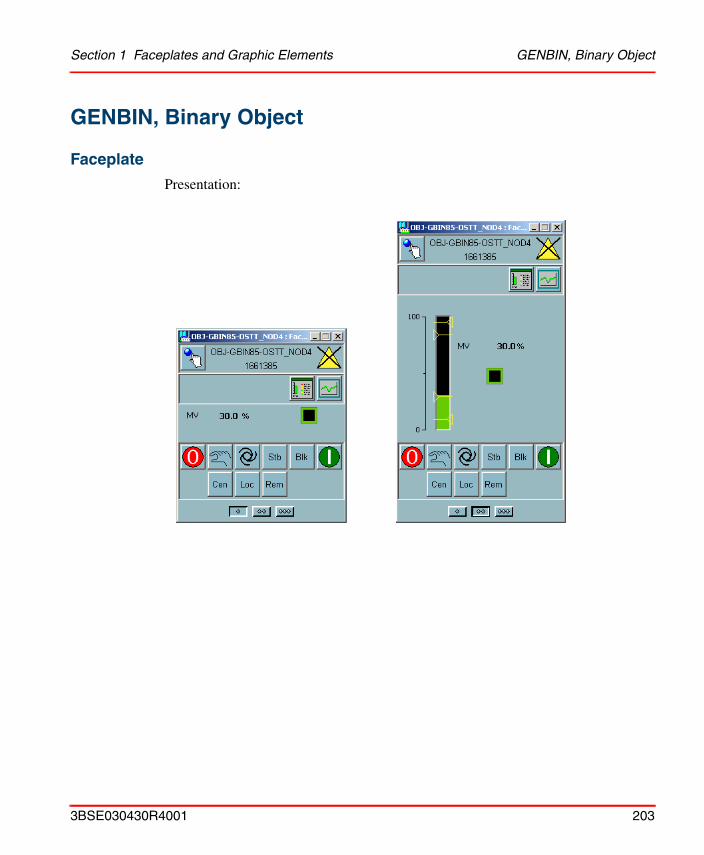
Section 1 Faceplates and Graphic Elements GENBIN, Binary Object
GENBIN, Binary Object
Faceplate
Presentation:
3BSE030430R4001 203
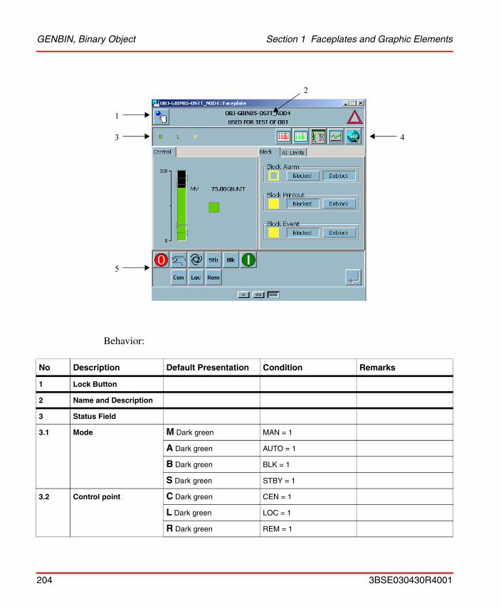
GENBIN, Binary Object Section 1 Faceplates and Graphic Elements
Behavior:
No Description Default Presentation Condition Remarks
1 Lock Button
2 Name and Description
3 Status Field
3.1 Mode M Dark green MAN = 1
A Dark green AUTO = 1
B Dark green BLK = 1
S Dark green STBY = 1
3.2 Control point C Dark green CEN = 1
L Dark green LOC = 1
R Dark green REM = 1
1
3
5
4
2
204 3BSE030430R4001
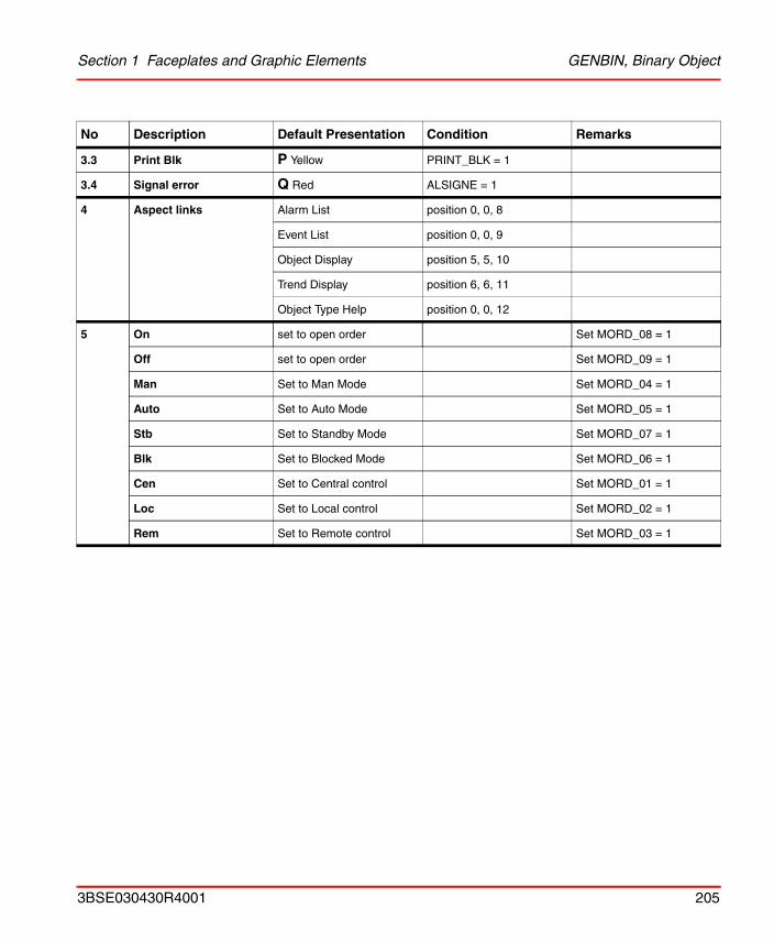
Section 1 Faceplates and Graphic Elements GENBIN, Binary Object
3.3 Print Blk P Yellow PRINT_BLK = 1
3.4 Signal error Q Red ALSIGNE = 1
4 Aspect links Alarm List position 0, 0, 8
Event List position 0, 0, 9
Object Display position 5, 5, 10
Trend Display position 6, 6, 11
Object Type Help position 0, 0, 12
5 On set to open order Set MORD_08 = 1
Off set to open order Set MORD_09 = 1
Man Set to Man Mode Set MORD_04 = 1
Auto Set to Auto Mode Set MORD_05 = 1
Stb Set to Standby Mode Set MORD_07 = 1
Blk Set to Blocked Mode Set MORD_06 = 1
Cen Set to Central control Set MORD_01 = 1
Loc Set to Local control Set MORD_02 = 1
Rem Set to Remote control Set MORD_03 = 1
No Description Default Presentation Condition Remarks
3BSE030430R4001 205
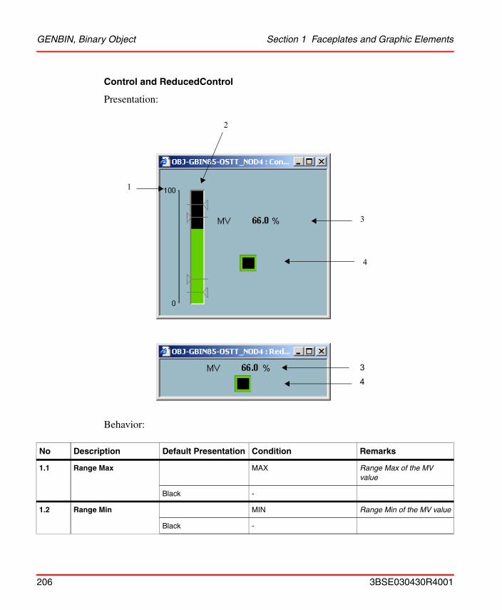
GENBIN, Binary Object Section 1 Faceplates and Graphic Elements
Control and ReducedControl
Presentation:
Behavior:
No Description Default Presentation Condition Remarks
1.1 Range Max MAX Range Max of the MV value
Black -
1.2 Range Min MIN Range Min of the MV value
Black -
1
3
2
4
34
206 3BSE030430R4001
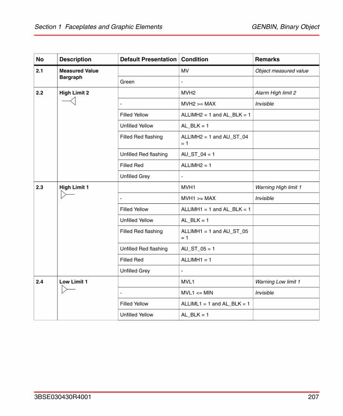
Section 1 Faceplates and Graphic Elements GENBIN, Binary Object
2.1 Measured Value Bargraph
MV Object measured value
Green -
2.2 High Limit 2 MVH2 Alarm High limit 2
- MVH2 >= MAX Invisible
Filled Yellow ALLIMH2 = 1 and AL_BLK = 1
Unfilled Yellow AL_BLK = 1
Filled Red flashing ALLIMH2 = 1 and AU_ST_04 = 1
Unfilled Red flashing AU_ST_04 = 1
Filled Red ALLIMH2 = 1
Unfilled Grey -
2.3 High Limit 1 MVH1 Warning High limit 1
- MVH1 >= MAX Invisible
Filled Yellow ALLIMH1 = 1 and AL_BLK = 1
Unfilled Yellow AL_BLK = 1
Filled Red flashing ALLIMH1 = 1 and AU_ST_05 = 1
Unfilled Red flashing AU_ST_05 = 1
Filled Red ALLIMH1 = 1
Unfilled Grey -
2.4 Low Limit 1 MVL1 Warning Low limit 1
- MVL1 <= MIN Invisible
Filled Yellow ALLIML1 = 1 and AL_BLK = 1
Unfilled Yellow AL_BLK = 1
No Description Default Presentation Condition Remarks
3BSE030430R4001 207
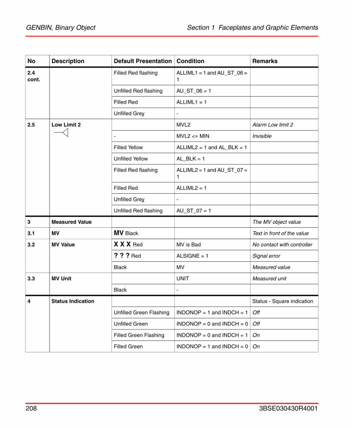
GENBIN, Binary Object Section 1 Faceplates and Graphic Elements
2.4 cont.
Filled Red flashing ALLIML1 = 1 and AU_ST_06 = 1
Unfilled Red flashing AU_ST_06 = 1
Filled Red ALLIML1 = 1
Unfilled Grey -
2.5 Low Limit 2 MVL2 Alarm Low limit 2
- MVL2 <= MIN Invisible
Filled Yellow ALLIML2 = 1 and AL_BLK = 1
Unfilled Yellow AL_BLK = 1
Filled Red flashing ALLIML2 = 1 and AU_ST_07 = 1
Filled Red ALLIML2 = 1
Unfilled Grey -
Unfilled Red flashing AU_ST_07 = 1
3 Measured Value The MV object value
3.1 MV MV Black Text in front of the value
3.2 MV Value X X X Red MV is Bad No contact with controller
? ? ? Red ALSIGNE = 1 Signal error
Black MV Measured value
3.3 MV Unit UNIT Measured unit
Black -
4 Status Indication Status - Square indication
Unfilled Green Flashing INDONOP = 1 and INDCH = 1 Off
Unfilled Green INDONOP = 0 and INDCH = 0 Off
Filled Green Flashing INDONOP = 0 and INDCH = 1 On
Filled Green INDONOP = 1 and INDCH = 0 On
No Description Default Presentation Condition Remarks
208 3BSE030430R4001
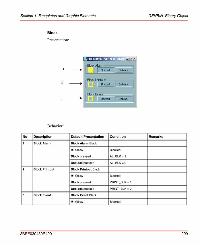
Section 1 Faceplates and Graphic Elements GENBIN, Binary Object
Block
Presentation:
Behavior:
No Description Default Presentation Condition Remarks
1 Block Alarm Block Alarm Black
! Yellow Blocked
Block pressed AL_BLK = 1
Deblock pressed AL_BLK = 0
2 Block Printout Block Printout Black
! Yellow Blocked
Block pressed PRINT_BLK = 1
Deblock pressed PRINT_BLK = 0
3 Block Event Block Event Black
! Yellow Blocked
1
2
3
3BSE030430R4001 209
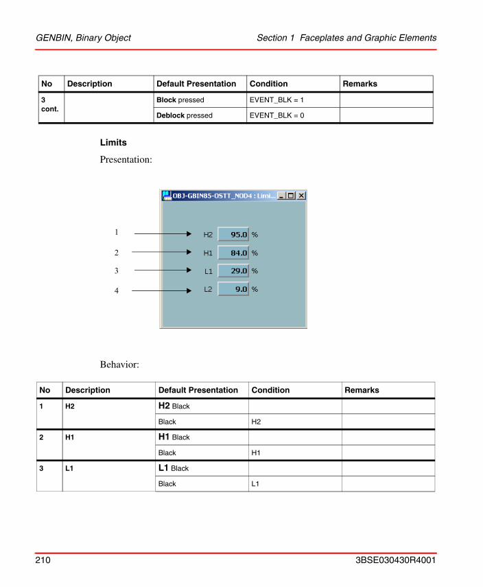
GENBIN, Binary Object Section 1 Faceplates and Graphic Elements
Limits
Presentation:
Behavior:
3 cont.
Block pressed EVENT_BLK = 1
Deblock pressed EVENT_BLK = 0
No Description Default Presentation Condition Remarks
1 H2 H2 Black
Black H2
2 H1 H1 Black
Black H1
3 L1 L1 Black
Black L1
No Description Default Presentation Condition Remarks
1
2
3
4
210 3BSE030430R4001
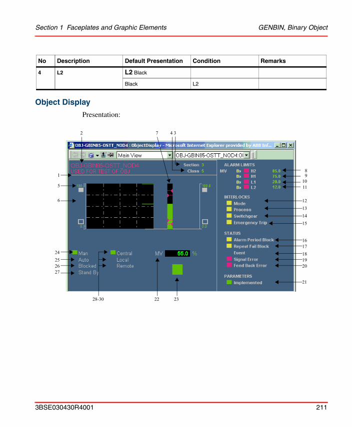
Section 1 Faceplates and Graphic Elements GENBIN, Binary Object
Object Display
Presentation:
4 L2 L2 Black
Black L2
No Description Default Presentation Condition Remarks
8
11
12
1
2 4 37
5
6
24
2627
910
131415
1617181920
21
232228-30
25
3BSE030430R4001 211
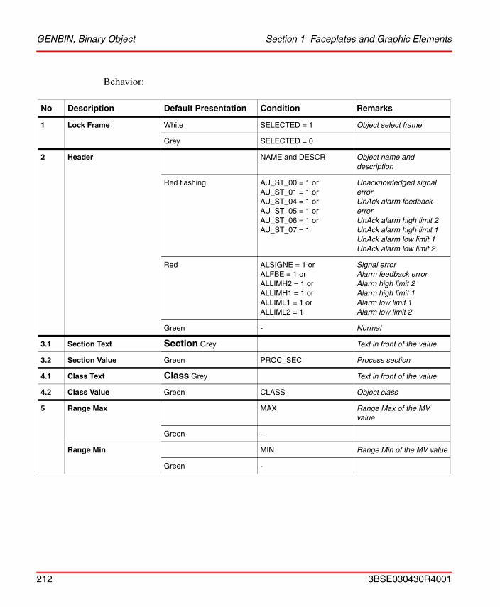
GENBIN, Binary Object Section 1 Faceplates and Graphic Elements
Behavior:
No Description Default Presentation Condition Remarks
1 Lock Frame White SELECTED = 1 Object select frame
Grey SELECTED = 0
2 Header NAME and DESCR Object name and description
Red flashing AU_ST_00 = 1 orAU_ST_01 = 1 orAU_ST_04 = 1 orAU_ST_05 = 1 or AU_ST_06 = 1 or AU_ST_07 = 1
Unacknowledged signal errorUnAck alarm feedback errorUnAck alarm high limit 2UnAck alarm high limit 1UnAck alarm low limit 1UnAck alarm low limit 2
Red ALSIGNE = 1 or ALFBE = 1 orALLIMH2 = 1 orALLIMH1 = 1 orALLIML1 = 1 orALLIML2 = 1
Signal errorAlarm feedback errorAlarm high limit 2Alarm high limit 1Alarm low limit 1Alarm low limit 2
Green - Normal
3.1 Section Text Section Grey Text in front of the value
3.2 Section Value Green PROC_SEC Process section
4.1 Class Text Class Grey Text in front of the value
4.2 Class Value Green CLASS Object class
5 Range Max MAX Range Max of the MV value
Green -
Range Min MIN Range Min of the MV value
Green -
212 3BSE030430R4001
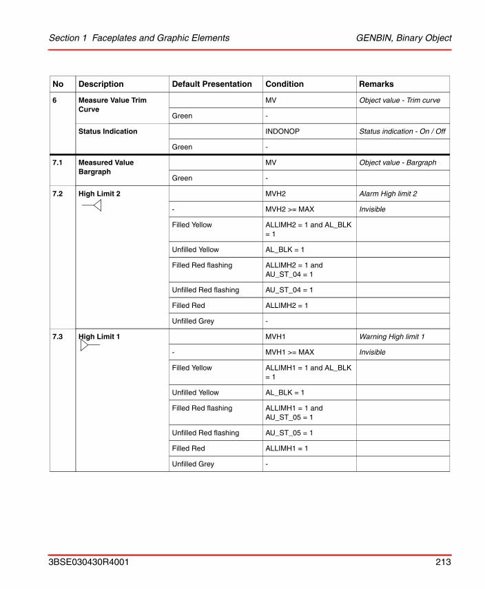
Section 1 Faceplates and Graphic Elements GENBIN, Binary Object
6 Measure Value Trim Curve
MV Object value - Trim curve
Green -
Status Indication INDONOP Status indication - On / Off
Green -
7.1 Measured Value Bargraph
MV Object value - Bargraph
Green -
7.2 High Limit 2 MVH2 Alarm High limit 2
- MVH2 >= MAX Invisible
Filled Yellow ALLIMH2 = 1 and AL_BLK = 1
Unfilled Yellow AL_BLK = 1
Filled Red flashing ALLIMH2 = 1 and AU_ST_04 = 1
Unfilled Red flashing AU_ST_04 = 1
Filled Red ALLIMH2 = 1
Unfilled Grey -
7.3 High Limit 1 MVH1 Warning High limit 1
- MVH1 >= MAX Invisible
Filled Yellow ALLIMH1 = 1 and AL_BLK = 1
Unfilled Yellow AL_BLK = 1
Filled Red flashing ALLIMH1 = 1 and AU_ST_05 = 1
Unfilled Red flashing AU_ST_05 = 1
Filled Red ALLIMH1 = 1
Unfilled Grey -
No Description Default Presentation Condition Remarks
3BSE030430R4001 213
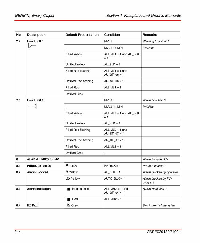
GENBIN, Binary Object Section 1 Faceplates and Graphic Elements
7.4 Low Limit 1 MVL1 Warning Low limit 1
- MVL1 <= MIN Invisible
Filled Yellow ALLIML1 = 1 and AL_BLK = 1
Unfilled Yellow AL_BLK = 1
Filled Red flashing ALLIML1 = 1 and AU_ST_06 = 1
Unfilled Red flashing AU_ST_06 = 1
Filled Red ALLIML1 = 1
Unfilled Grey -
7.5 Low Limit 2 MVL2 Alarm Low limit 2
- MVL2 <= MIN Invisible
Filled Yellow ALLIML2 = 1 and AL_BLK = 1
Unfilled Yellow AL_BLK = 1
Filled Red flashing ALLIML2 = 1 and AU_ST_07 = 1
Unfilled Red flashing AU_ST_07 = 1
Filled Red ALLIML2 = 1
Unfilled Grey -
8 ALARM LIMITS for MV Alarm limits for MV
8.1 Printout Blocked P Yellow PR_BLK = 1 Printout blocked
8.2 Alarm Blocked B Yellow AL_BLK = 1 Alarm blocked by operator
Bx Yellow AUTO_BLK = 1 Alarm blocked by PC-program
8.3 Alarm Indication Red flashing ALLIMH2 = 1 and AU_ST_04 = 1
Alarm High limit 2
Red ALLIMH2 = 1
8.4 H2 Text H2 Grey Text in front of the value
No Description Default Presentation Condition Remarks
214 3BSE030430R4001
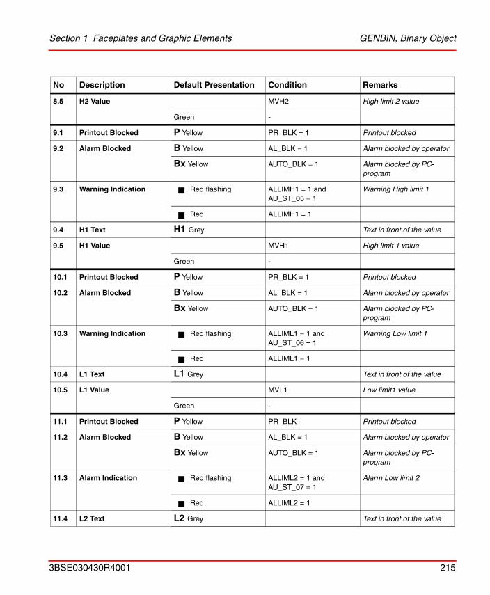
Section 1 Faceplates and Graphic Elements GENBIN, Binary Object
8.5 H2 Value MVH2 High limit 2 value
Green -
9.1 Printout Blocked P Yellow PR_BLK = 1 Printout blocked
9.2 Alarm Blocked B Yellow AL_BLK = 1 Alarm blocked by operator
Bx Yellow AUTO_BLK = 1 Alarm blocked by PC-program
9.3 Warning Indication Red flashing ALLIMH1 = 1 and AU_ST_05 = 1
Warning High limit 1
Red ALLIMH1 = 1
9.4 H1 Text H1 Grey Text in front of the value
9.5 H1 Value MVH1 High limit 1 value
Green -
10.1 Printout Blocked P Yellow PR_BLK = 1 Printout blocked
10.2 Alarm Blocked B Yellow AL_BLK = 1 Alarm blocked by operator
Bx Yellow AUTO_BLK = 1 Alarm blocked by PC-program
10.3 Warning Indication Red flashing ALLIML1 = 1 and AU_ST_06 = 1
Warning Low limit 1
Red ALLIML1 = 1
10.4 L1 Text L1 Grey Text in front of the value
10.5 L1 Value MVL1 Low limit1 value
Green -
11.1 Printout Blocked P Yellow PR_BLK Printout blocked
11.2 Alarm Blocked B Yellow AL_BLK = 1 Alarm blocked by operator
Bx Yellow AUTO_BLK = 1 Alarm blocked by PC-program
11.3 Alarm Indication Red flashing ALLIML2 = 1 and AU_ST_07 = 1
Alarm Low limit 2
Red ALLIML2 = 1
11.4 L2 Text L2 Grey Text in front of the value
No Description Default Presentation Condition Remarks
3BSE030430R4001 215
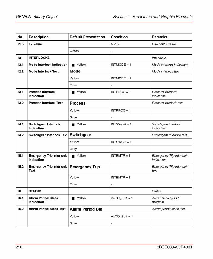
GENBIN, Binary Object Section 1 Faceplates and Graphic Elements
11.5 L2 Value MVL2 Low limit 2 value
Green -
12 INTERLOCKS Interlocks
12.1 Mode Interlock Indication Yellow INTMODE = 1 Mode interlock indication
12.2 Mode Interlock Text Mode Mode interlock text
Yellow INTMODE = 1
Grey -
13.1 Process Interlock Indication
Yellow INTPROC = 1 Process interlock indication
13.2 Process Interlock Text Process Process interlock text
Yellow INTPROC = 1
Grey -
14.1 Switchgear Interlock Indication
Yellow INTSWGR = 1 Switchgear interlock indication
14.2 Switchgear Interlock Text Switchgear Switchgear interlock text
Yellow INTSWGR = 1
Grey -
15.1 Emergency Trip Interlock Indication
Yellow INTEMTP = 1 Emergency Trip interlock indication
15.2 Emergency Trip Interlock Text
Emergency Trip Emergency Trip interlock text
Yellow INTEMTP = 1
Grey -
16 STATUS Status
16.1 Alarm Period Block Indication
Yellow AUTO_BLK = 1 Alarm block by PC-program
16.2 Alarm Period Block Text Alarm Period Blk Alarm period block text
Yellow AUTO_BLK = 1
Grey -
No Description Default Presentation Condition Remarks
216 3BSE030430R4001
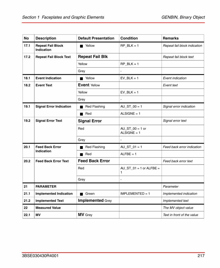
Section 1 Faceplates and Graphic Elements GENBIN, Binary Object
17.1 Repeat Fail Block Indication
Yellow RP_BLK = 1 Repeat fail block indication
17.2 Repeat Fail Block Text Repeat Fail Blk Repeat fail block text
Yellow RP_BLK = 1
Grey -
18.1 Event Indication Yellow EV_BLK = 1 Event indication
18.2 Event Text Event Yellow Event text
Yellow EV_BLK = 1
Grey -
19.1 Signal Error Indication Red Flashing AU_ST_00 = 1 Signal error indication
Red ALSIGNE = 1
19.2 Signal Error Text Signal Error Signal error text
Red AU_ST_00 = 1 or ALSIGNE = 1
Grey -
20.1 Feed Back Error Indication
Red Flashing AU_ST_01 = 1 Feed back error indication
Red ALFBE = 1
20.2 Feed Back Error Text Feed Back Error Feed back error text
Red AU_ST_01 = 1 or ALFBE = 1
Grey -
21 PARAMETER Parameter
21.1 Implemented Indication Green IMPLEMENTED = 1 Implemented indication
21.2 Implemented Text Implemented Grey Implemented text
22 Measured Value The MV object value
22.1 MV MV Grey Text in front of the value
No Description Default Presentation Condition Remarks
3BSE030430R4001 217
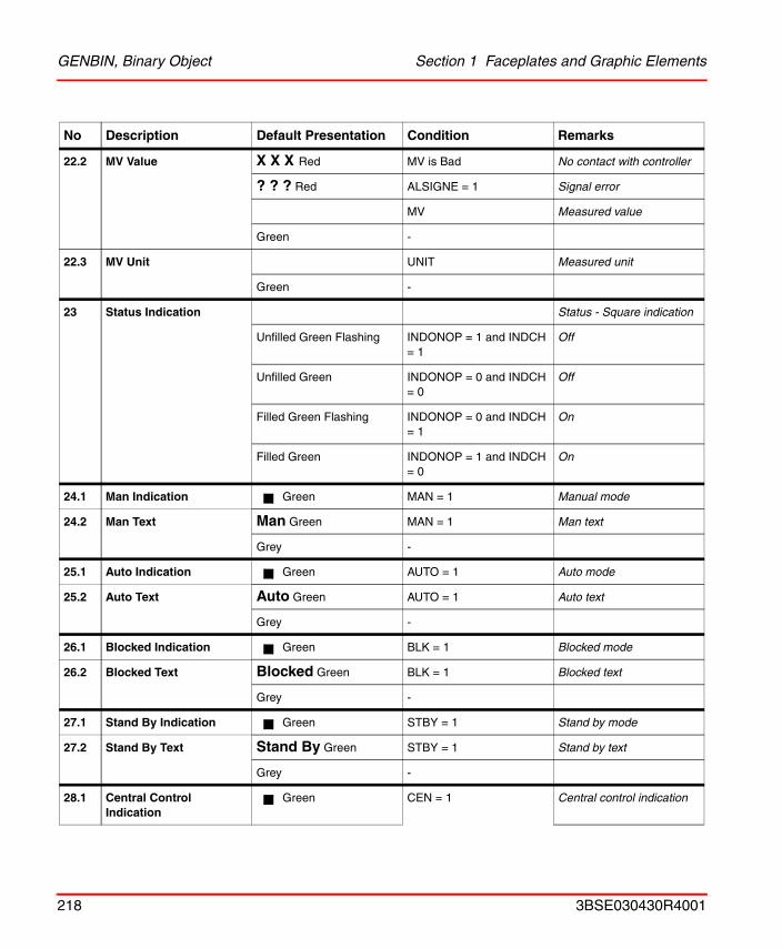
GENBIN, Binary Object Section 1 Faceplates and Graphic Elements
22.2 MV Value X X X Red MV is Bad No contact with controller
? ? ? Red ALSIGNE = 1 Signal error
MV Measured value
Green -
22.3 MV Unit UNIT Measured unit
Green -
23 Status Indication Status - Square indication
Unfilled Green Flashing INDONOP = 1 and INDCH = 1
Off
Unfilled Green INDONOP = 0 and INDCH = 0
Off
Filled Green Flashing INDONOP = 0 and INDCH = 1
On
Filled Green INDONOP = 1 and INDCH = 0
On
24.1 Man Indication Green MAN = 1 Manual mode
24.2 Man Text Man Green MAN = 1 Man text
Grey -
25.1 Auto Indication Green AUTO = 1 Auto mode
25.2 Auto Text Auto Green AUTO = 1 Auto text
Grey -
26.1 Blocked Indication Green BLK = 1 Blocked mode
26.2 Blocked Text Blocked Green BLK = 1 Blocked text
Grey -
27.1 Stand By Indication Green STBY = 1 Stand by mode
27.2 Stand By Text Stand By Green STBY = 1 Stand by text
Grey -
28.1 Central Control Indication
Green CEN = 1 Central control indication
No Description Default Presentation Condition Remarks
218 3BSE030430R4001
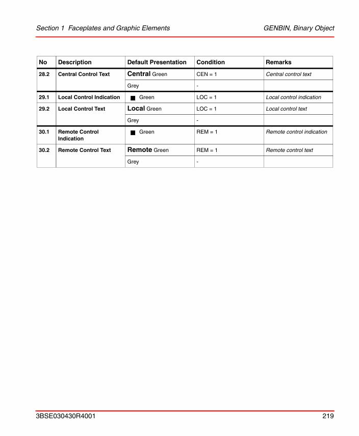
Section 1 Faceplates and Graphic Elements GENBIN, Binary Object
28.2 Central Control Text Central Green CEN = 1 Central control text
Grey -
29.1 Local Control Indication Green LOC = 1 Local control indication
29.2 Local Control Text Local Green LOC = 1 Local control text
Grey -
30.1 Remote Control Indication
Green REM = 1 Remote control indication
30.2 Remote Control Text Remote Green REM = 1 Remote control text
Grey -
No Description Default Presentation Condition Remarks
3BSE030430R4001 219

GENBIN, Binary Object Section 1 Faceplates and Graphic Elements
Graphic Element
Numeric
Presentation:
21
4 3
5
6
220 3BSE030430R4001
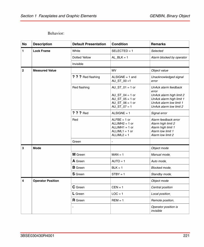
Section 1 Faceplates and Graphic Elements GENBIN, Binary Object
Behavior:
No Description Default Presentation Condition Remarks
1 Lock Frame White SELECTED = 1 Selected
Dotted Yellow AL_BLK = 1 Alarm blocked by operator
Invisible
2 Measured Value MV Object value
? ? ? Red flashing ALSIGNE = 1 and AU_ST_00 =1
Unacknowledged signal error
Red flashing AU_ST_01 = 1 or
AU_ST_04 = 1 orAU_ST_05 = 1 orAU_ST_06 = 1 orAU_ST_07 = 1
UnAck alarm feedback errorUnAck alarm high limit 2UnAck alarm high limit 1UnAck alarm low limit 1UnAck alarm low limit 2
? ? ? Red ALSIGNE = 1 Signal error
Red ALFBE = 1 orALLIMH2 = 1 orALLIMH1 = 1 orALLIML1 = 1 orALLIML2 = 1
Alarm feedback errorAlarm high limit 2Alarm high limit 1Alarm low limit 1Alarm low limit 2
Green -
3 Mode Object mode
M Green MAN = 1 Manual mode
A Green AUTO = 1 Auto mode
B Green BLK = 1 Blocked mode
S Green STBY = 1 Standby mode
4 Operator Position Object mode
C Green CEN = 1 Central position
L Green LOC = 1 Local position
R Green REM = 1 Remote position
- Operator position is invisible
3BSE030430R4001 221
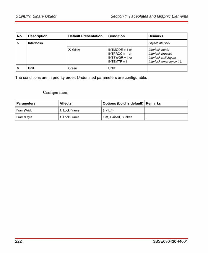
GENBIN, Binary Object Section 1 Faceplates and Graphic Elements
The conditions are in priority order. Underlined parameters are configurable.
Configuration:
5 Interlocks Object interlock
X Yellow INTMODE = 1 orINTPROC = 1 orINTSWGR = 1 orINTEMTP = 1
Interlock modeInterlock processInterlock switchgearInterlock emergency trip
6 Unit Green UNIT
Parameters Affects Options (bold is default) Remarks
FrameWidth 1. Lock Frame 3, (1..4)
FrameStyle 1. Lock Frame Flat, Raised, Sunken
No Description Default Presentation Condition Remarks
222 3BSE030430R4001
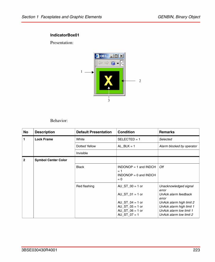
Section 1 Faceplates and Graphic Elements GENBIN, Binary Object
IndicatorBox01
Presentation:
Behavior:
No Description Default Presentation Condition Remarks
1 Lock Frame White SELECTED = 1 Selected
Dotted Yellow AL_BLK = 1 Alarm blocked by operator
Invisible
2 Symbol Center Color
Black INDONOP = 1 and INDCH = 1INDONOP = 0 and INDCH = 0
Off
Red flashing AU_ST_00 = 1 or
AU_ST_01 = 1 or
AU_ST_04 = 1 orAU_ST_05 = 1 or AU_ST_06 = 1 or AU_ST_07 = 1
Unacknowledged signal errorUnAck alarm feedback errorUnAck alarm high limit 2UnAck alarm high limit 1UnAck alarm low limit 1UnAck alarm low limit 2
1
2
3
3BSE030430R4001 223
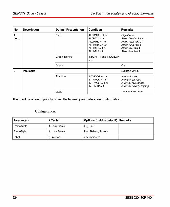
GENBIN, Binary Object Section 1 Faceplates and Graphic Elements
The conditions are in priority order. Underlined parameters are configurable.
Configuration:
2 cont.
Red ALSIGNE = 1 or ALFBE = 1 orALLIMH2 = 1 orALLIMH1 = 1 orALLIML1 = 1 orALLIML2 = 1
Signal errorAlarm feedback errorAlarm high limit 2Alarm high limit 1Alarm low limit 1Alarm low limit 2
Green flashing INDCH = 1 and INDONOP = 0
Green - On
3 Interlocks Object interlock
X Yellow INTMODE = 1 orINTPROC = 1 orINTSWGR = 1 orINTEMTP = 1
Interlock modeInterlock processInterlock switchgearInterlock emergency trip
Label - User defined Label
Parameters Affects Options (bold is default) Remarks
FrameWidth 1. Lock Frame 3, (0...5)
FrameStyle 1. Lock Frame Flat, Raised, Sunken
Label 3. Interlock Any character
No Description Default Presentation Condition Remarks
224 3BSE030430R4001
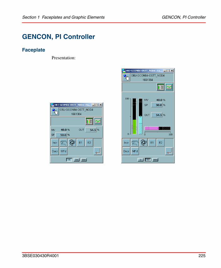
Section 1 Faceplates and Graphic Elements GENCON, PI Controller
GENCON, PI Controller
Faceplate
Presentation:
3BSE030430R4001 225
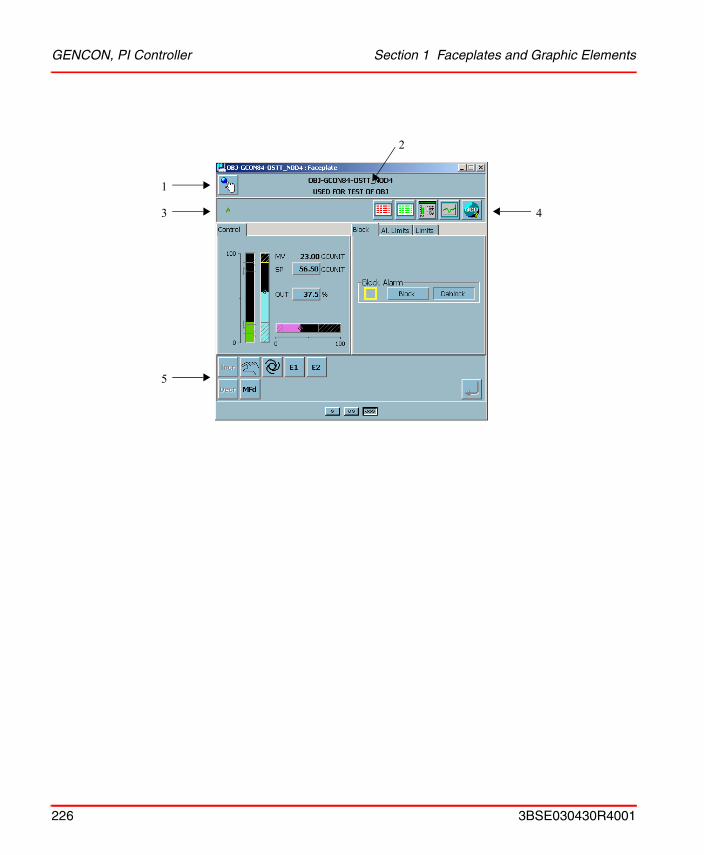
GENCON, PI Controller Section 1 Faceplates and Graphic Elements
1
3
5
2
4
226 3BSE030430R4001
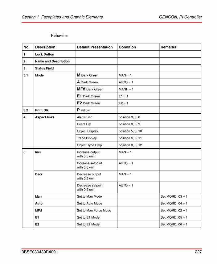
Section 1 Faceplates and Graphic Elements GENCON, PI Controller
Behavior:
No Description Default Presentation Condition Remarks
1 Lock Button
2 Name and Description
3 Status Field
3.1 Mode M Dark Green MAN = 1
A Dark Green AUTO = 1
MFd Dark Green MANF = 1
E1 Dark Green E1 = 1
E2 Dark Green E2 = 1
3.2 Print Blk P Yellow
4 Aspect links Alarm List position 0, 0, 8
Event List position 0, 0, 9
Object Display position 5, 5, 10
Trend Display position 6, 6, 11
Object Type Help position 0, 0, 12
5 Incr Increase output with 0,5 unit
MAN = 1
Increase setpoint with 0,5 unit
AUTO = 1
Decr Decrease outputwith 0,5 unit
MAN = 1
Decrease setpoint with 0,5 unit
AUTO = 1
Man Set to Man Mode Set MORD_03 = 1
Auto Set to Auto Mode Set MORD_04 = 1
MFd Set to Man Force Mode Set MORD_02 = 1
E1 Set to E1 Mode Set MORD_05 = 1
E2 Set to E2 Mode Set MORD_06 = 1
3BSE030430R4001 227
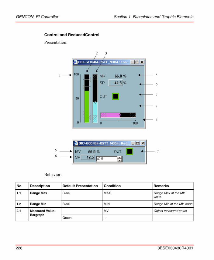
GENCON, PI Controller Section 1 Faceplates and Graphic Elements
Control and ReducedControl
Presentation:
Behavior:
No Description Default Presentation Condition Remarks
1.1 Range Max Black MAX Range Max of the MV value
1.2 Range Min Black MIN Range Min of the MV value
2.1 Measured Value Bargraph
MV Object measured value
Green -
51
4
3
6
7
2
8
756
228 3BSE030430R4001
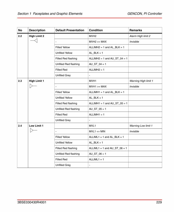
Section 1 Faceplates and Graphic Elements GENCON, PI Controller
2.2 High Limit 2 MVH2 Alarm High limit 2
- MVH2 >= MAX Invisible
Filled Yellow ALLIMH2 = 1 and AL_BLK = 1
Unfilled Yellow AL_BLK = 1
Filled Red flashing ALLIMH2 = 1 and AU_ST_04 = 1
Unfilled Red flashing AU_ST_04 = 1
Filled Red ALLIMH2 = 1
Unfilled Grey -
2.3 High Limit 1 MVH1 Warning High limit 1
- MVH1 >= MAX Invisible
Filled Yellow ALLIMH1 = 1 and AL_BLK = 1
Unfilled Yellow AL_BLK = 1
Filled Red flashing ALLIMH1 = 1 and AU_ST_05 = 1
Unfilled Red flashing AU_ST_05 = 1
Filled Red ALLIMH1 = 1
Unfilled Grey -
2.4 Low Limit 1 MVL1 Warning Low limit 1
- MVL1 <= MIN Invisible
Filled Yellow ALLIML1 = 1 and AL_BLK = 1
Unfilled Yellow AL_BLK = 1
Filled Red flashing ALLIML1 = 1 and AU_ST_06 = 1
Unfilled Red flashing AU_ST_06 = 1
Filled Red ALLIML1 = 1
Unfilled Grey -
No Description Default Presentation Condition Remarks
3BSE030430R4001 229
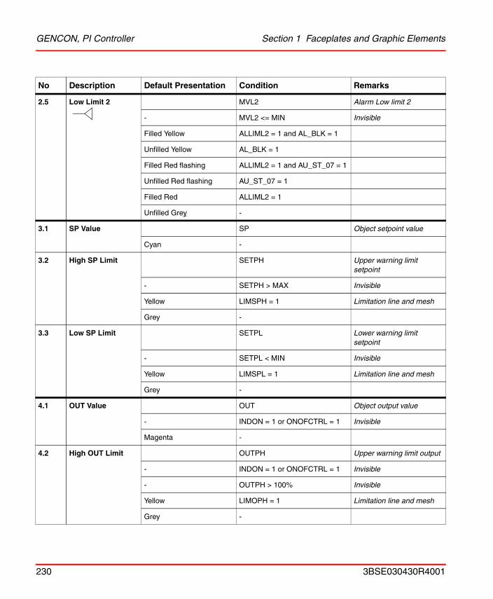
GENCON, PI Controller Section 1 Faceplates and Graphic Elements
2.5 Low Limit 2 MVL2 Alarm Low limit 2
- MVL2 <= MIN Invisible
Filled Yellow ALLIML2 = 1 and AL_BLK = 1
Unfilled Yellow AL_BLK = 1
Filled Red flashing ALLIML2 = 1 and AU_ST_07 = 1
Unfilled Red flashing AU_ST_07 = 1
Filled Red ALLIML2 = 1
Unfilled Grey -
3.1 SP Value SP Object setpoint value
Cyan -
3.2 High SP Limit SETPH Upper warning limit setpoint
- SETPH > MAX Invisible
Yellow LIMSPH = 1 Limitation line and mesh
Grey -
3.3 Low SP Limit SETPL Lower warning limit setpoint
- SETPL < MIN Invisible
Yellow LIMSPL = 1 Limitation line and mesh
Grey -
4.1 OUT Value OUT Object output value
- INDON = 1 or ONOFCTRL = 1 Invisible
Magenta -
4.2 High OUT Limit OUTPH Upper warning limit output
- INDON = 1 or ONOFCTRL = 1 Invisible
- OUTPH > 100% Invisible
Yellow LIMOPH = 1 Limitation line and mesh
Grey -
No Description Default Presentation Condition Remarks
230 3BSE030430R4001
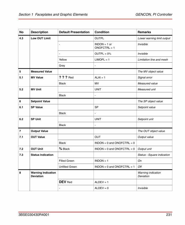
Section 1 Faceplates and Graphic Elements GENCON, PI Controller
4.3 Low OUT Limit OUTPL Lower warning limit output
- INDON = 1 or ONOFCTRL = 1
Invisible
- OUTPL < 0% Invisible
Yellow LIMOPL = 1 Limitation line and mesh
Grey -
5 Measured Value The MV object value
5.1 MV Value ? ? ? Red ALAI = 1 Signal error
Black MV Measured value
5.2 MV Unit UNIT Measured unit
Black -
6 Setpoint Value The SP object value
6.1 SP Value SP Setpoint value
Black -
6.2 SP Unit UNIT Setpoint unit
Black -
7 Output Value The OUT object value
7.1 OUT Value OUT Output value
Black INDON = 0 and ONOFCTRL = 0
7.2 OUT Unit % Black INDON = 0 and ONOFCTRL = 0 Output unit
7.3 Status Indication Status - Square indication
Filled Green INDON = 1 On
Unfilled Green INDON = 0 and ONOFCTRL = 1 Off
8 Warning Indication Deviation
Warning indication Deviation
DEV Red ALDEV = 1
- ALDEV = 0 Invisible
No Description Default Presentation Condition Remarks
3BSE030430R4001 231
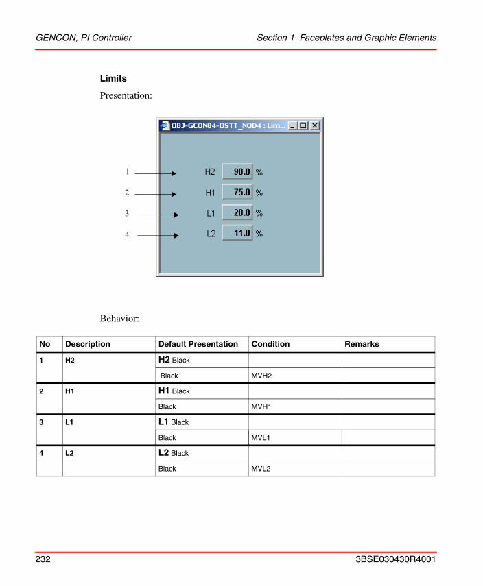
GENCON, PI Controller Section 1 Faceplates and Graphic Elements
Limits
Presentation:
Behavior:
No Description Default Presentation Condition Remarks
1 H2 H2 Black
Black MVH2
2 H1 H1 Black
Black MVH1
3 L1 L1 Black
Black MVL1
4 L2 L2 Black
Black MVL2
2
3
1
4
232 3BSE030430R4001
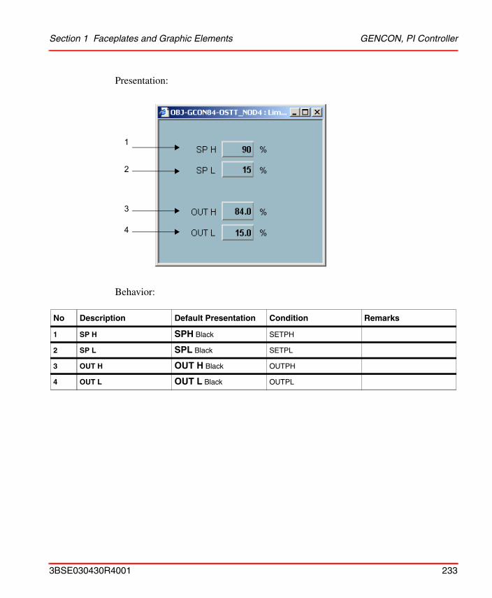
Section 1 Faceplates and Graphic Elements GENCON, PI Controller
Presentation:
Behavior:
No Description Default Presentation Condition Remarks
1 SP H SPH Black SETPH
2 SP L SPL Black SETPL
3 OUT H OUT H Black OUTPH
4 OUT L OUT L Black OUTPL
1
2
3
4
3BSE030430R4001 233
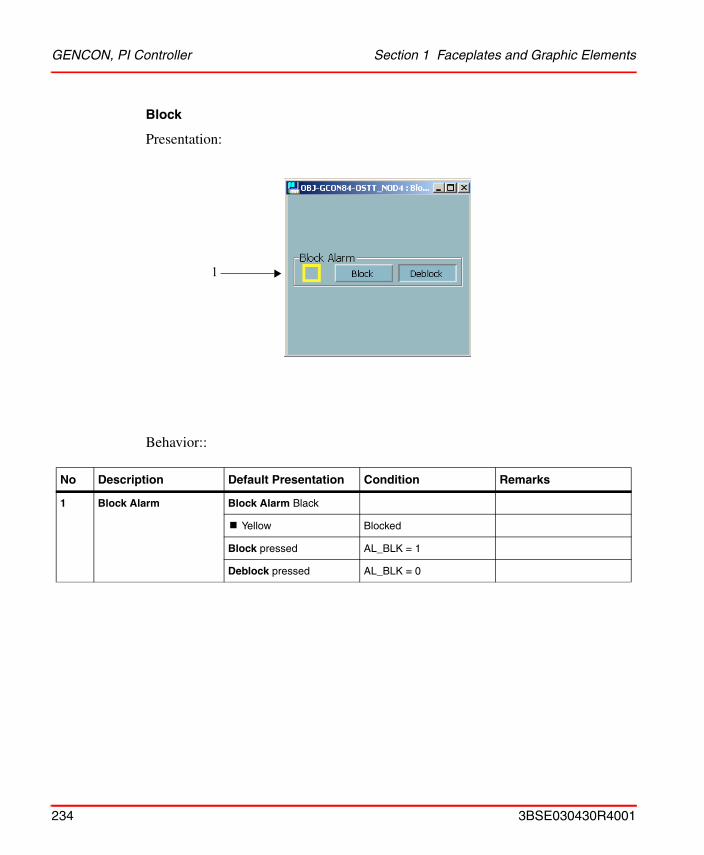
GENCON, PI Controller Section 1 Faceplates and Graphic Elements
Block
Presentation:
Behavior::
No Description Default Presentation Condition Remarks
1 Block Alarm Block Alarm Black
! Yellow Blocked
Block pressed AL_BLK = 1
Deblock pressed AL_BLK = 0
1
234 3BSE030430R4001
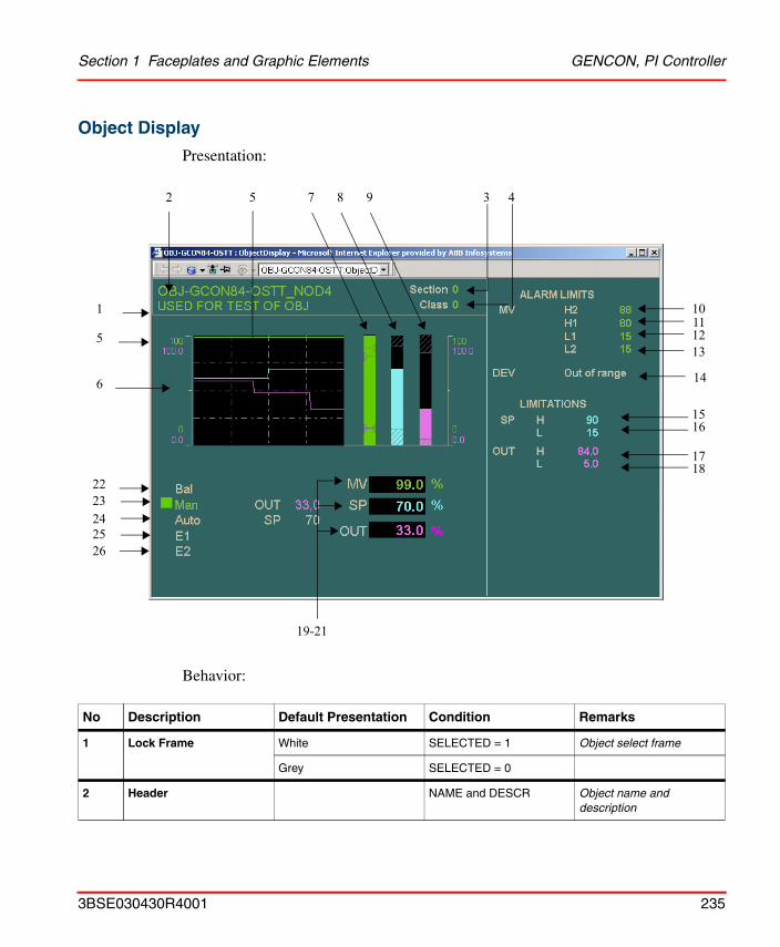
Section 1 Faceplates and Graphic Elements GENCON, PI Controller
Object Display
Presentation:
Behavior:
No Description Default Presentation Condition Remarks
1 Lock Frame White SELECTED = 1 Object select frame
Grey SELECTED = 0
2 Header NAME and DESCR Object name and description
5
10
3 42
1
5
6
2223
19-21
111213
1516
7 8 9
1718
242526
14
3BSE030430R4001 235
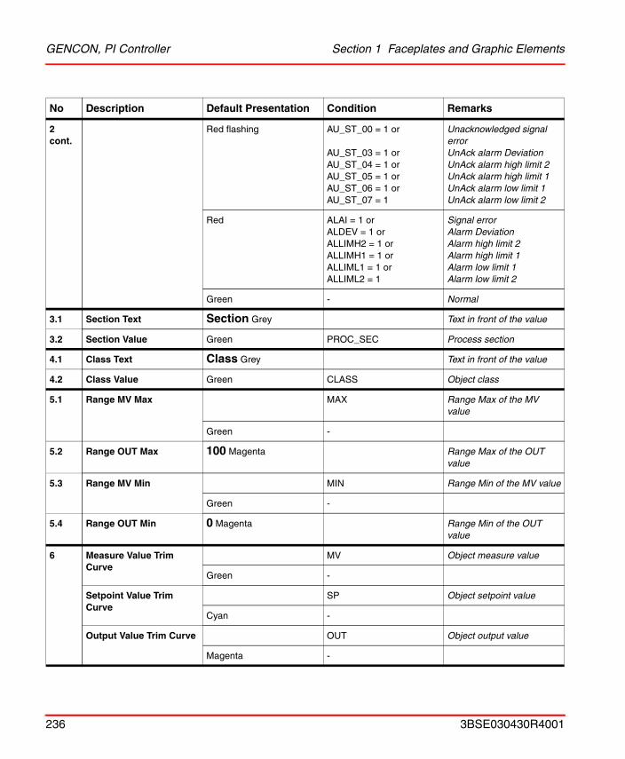
GENCON, PI Controller Section 1 Faceplates and Graphic Elements
2 cont.
Red flashing AU_ST_00 = 1 or
AU_ST_03 = 1 orAU_ST_04 = 1 orAU_ST_05 = 1 orAU_ST_06 = 1 orAU_ST_07 = 1
Unacknowledged signal errorUnAck alarm Deviation UnAck alarm high limit 2UnAck alarm high limit 1UnAck alarm low limit 1UnAck alarm low limit 2
Red ALAI = 1 orALDEV = 1 orALLIMH2 = 1 orALLIMH1 = 1 orALLIML1 = 1 orALLIML2 = 1
Signal errorAlarm Deviation Alarm high limit 2Alarm high limit 1Alarm low limit 1Alarm low limit 2
Green - Normal
3.1 Section Text Section Grey Text in front of the value
3.2 Section Value Green PROC_SEC Process section
4.1 Class Text Class Grey Text in front of the value
4.2 Class Value Green CLASS Object class
5.1 Range MV Max MAX Range Max of the MV value
Green -
5.2 Range OUT Max 100 Magenta Range Max of the OUT value
5.3 Range MV Min MIN Range Min of the MV value
Green -
5.4 Range OUT Min 0 Magenta Range Min of the OUT value
6 Measure Value Trim Curve
MV Object measure value
Green -
Setpoint Value Trim Curve
SP Object setpoint value
Cyan -
Output Value Trim Curve OUT Object output value
Magenta -
No Description Default Presentation Condition Remarks
236 3BSE030430R4001
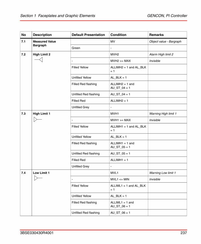
Section 1 Faceplates and Graphic Elements GENCON, PI Controller
7.1 Measured Value Bargraph
MV Object value - Bargraph
Green -
7.2 High Limit 2 MVH2 Alarm High limit 2
- MVH2 >= MAX Invisible
Filled Yellow ALLIMH2 = 1 and AL_BLK = 1
Unfilled Yellow AL_BLK = 1
Filled Red flashing ALLIMH2 = 1 and AU_ST_04 = 1
Unfilled Red flashing AU_ST_04 = 1
Filled Red ALLIMH2 = 1
Unfilled Grey -
7.3 High Limit 1 MVH1 Warning High limit 1
- MVH1 >= MAX Invisible
Filled Yellow ALLIMH1 = 1 and AL_BLK = 1
Unfilled Yellow AL_BLK = 1
Filled Red flashing ALLIMH1 = 1 and AU_ST_05 = 1
Unfilled Red flashing AU_ST_05 = 1
Filled Red ALLIMH1 = 1
Unfilled Grey -
7.4 Low Limit 1 MVL1 Warning Low limit 1
- MVL1 <= MIN Invisible
Filled Yellow ALLIML1 = 1 and AL_BLK = 1
Unfilled Yellow AL_BLK = 1
Filled Red flashing ALLIML1 = 1 and AU_ST_06 = 1
Unfilled Red flashing AU_ST_06 = 1
No Description Default Presentation Condition Remarks
3BSE030430R4001 237
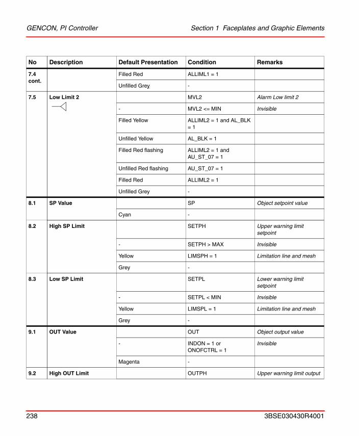
GENCON, PI Controller Section 1 Faceplates and Graphic Elements
7.4 cont.
Filled Red ALLIML1 = 1
Unfilled Grey -
7.5 Low Limit 2 MVL2 Alarm Low limit 2
- MVL2 <= MIN Invisible
Filled Yellow ALLIML2 = 1 and AL_BLK = 1
Unfilled Yellow AL_BLK = 1
Filled Red flashing ALLIML2 = 1 and AU_ST_07 = 1
Unfilled Red flashing AU_ST_07 = 1
Filled Red ALLIML2 = 1
Unfilled Grey -
8.1 SP Value SP Object setpoint value
Cyan -
8.2 High SP Limit SETPH Upper warning limit setpoint
- SETPH > MAX Invisible
Yellow LIMSPH = 1 Limitation line and mesh
Grey -
8.3 Low SP Limit SETPL Lower warning limit setpoint
- SETPL < MIN Invisible
Yellow LIMSPL = 1 Limitation line and mesh
Grey -
9.1 OUT Value OUT Object output value
- INDON = 1 or ONOFCTRL = 1
Invisible
Magenta -
9.2 High OUT Limit OUTPH Upper warning limit output
No Description Default Presentation Condition Remarks
238 3BSE030430R4001
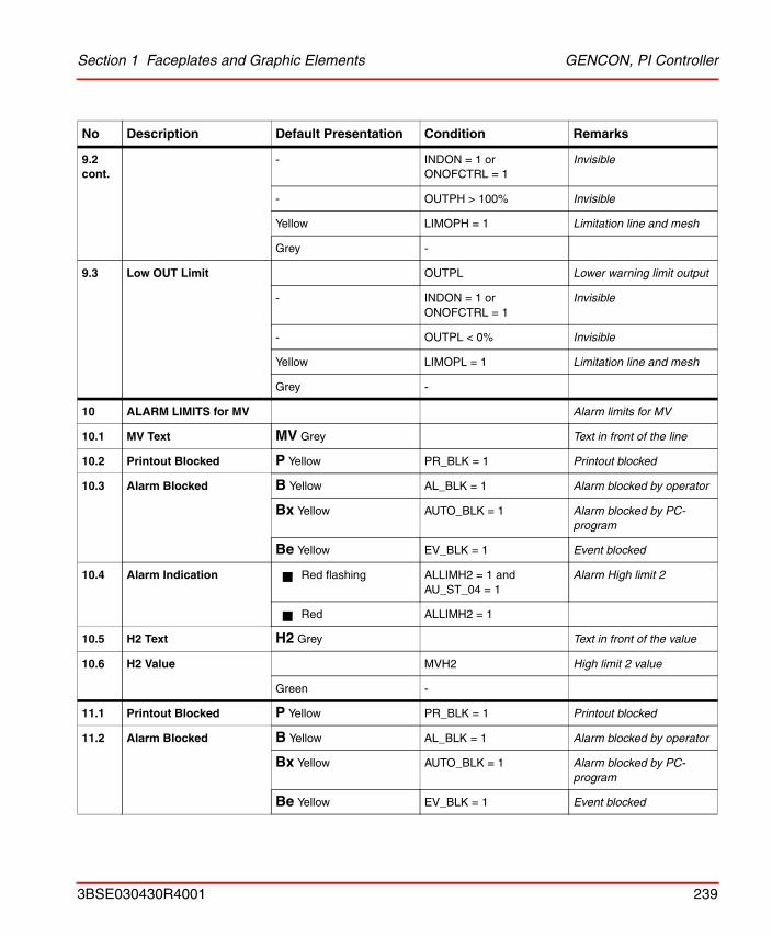
Section 1 Faceplates and Graphic Elements GENCON, PI Controller
9.2 cont.
- INDON = 1 or ONOFCTRL = 1
Invisible
- OUTPH > 100% Invisible
Yellow LIMOPH = 1 Limitation line and mesh
Grey -
9.3 Low OUT Limit OUTPL Lower warning limit output
- INDON = 1 or ONOFCTRL = 1
Invisible
- OUTPL < 0% Invisible
Yellow LIMOPL = 1 Limitation line and mesh
Grey -
10 ALARM LIMITS for MV Alarm limits for MV
10.1 MV Text MV Grey Text in front of the line
10.2 Printout Blocked P Yellow PR_BLK = 1 Printout blocked
10.3 Alarm Blocked B Yellow AL_BLK = 1 Alarm blocked by operator
Bx Yellow AUTO_BLK = 1 Alarm blocked by PC-program
Be Yellow EV_BLK = 1 Event blocked
10.4 Alarm Indication Red flashing ALLIMH2 = 1 and AU_ST_04 = 1
Alarm High limit 2
Red ALLIMH2 = 1
10.5 H2 Text H2 Grey Text in front of the value
10.6 H2 Value MVH2 High limit 2 value
Green -
11.1 Printout Blocked P Yellow PR_BLK = 1 Printout blocked
11.2 Alarm Blocked B Yellow AL_BLK = 1 Alarm blocked by operator
Bx Yellow AUTO_BLK = 1 Alarm blocked by PC-program
Be Yellow EV_BLK = 1 Event blocked
No Description Default Presentation Condition Remarks
3BSE030430R4001 239
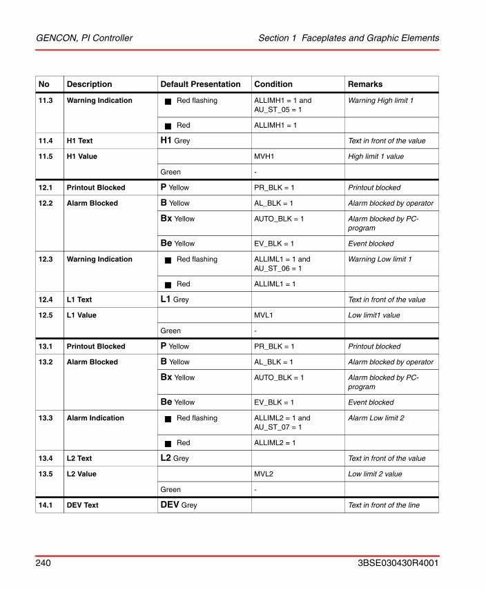
GENCON, PI Controller Section 1 Faceplates and Graphic Elements
11.3 Warning Indication Red flashing ALLIMH1 = 1 and AU_ST_05 = 1
Warning High limit 1
Red ALLIMH1 = 1
11.4 H1 Text H1 Grey Text in front of the value
11.5 H1 Value MVH1 High limit 1 value
Green -
12.1 Printout Blocked P Yellow PR_BLK = 1 Printout blocked
12.2 Alarm Blocked B Yellow AL_BLK = 1 Alarm blocked by operator
Bx Yellow AUTO_BLK = 1 Alarm blocked by PC-program
Be Yellow EV_BLK = 1 Event blocked
12.3 Warning Indication Red flashing ALLIML1 = 1 and AU_ST_06 = 1
Warning Low limit 1
Red ALLIML1 = 1
12.4 L1 Text L1 Grey Text in front of the value
12.5 L1 Value MVL1 Low limit1 value
Green -
13.1 Printout Blocked P Yellow PR_BLK = 1 Printout blocked
13.2 Alarm Blocked B Yellow AL_BLK = 1 Alarm blocked by operator
Bx Yellow AUTO_BLK = 1 Alarm blocked by PC-program
Be Yellow EV_BLK = 1 Event blocked
13.3 Alarm Indication Red flashing ALLIML2 = 1 and AU_ST_07 = 1
Alarm Low limit 2
Red ALLIML2 = 1
13.4 L2 Text L2 Grey Text in front of the value
13.5 L2 Value MVL2 Low limit 2 value
Green -
14.1 DEV Text DEV Grey Text in front of the line
No Description Default Presentation Condition Remarks
240 3BSE030430R4001
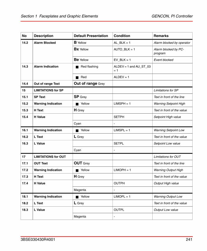
Section 1 Faceplates and Graphic Elements GENCON, PI Controller
14.2 Alarm Blocked B Yellow AL_BLK = 1 Alarm blocked by operator
Bx Yellow AUTO_BLK = 1 Alarm blocked by PC-program
Be Yellow EV_BLK = 1 Event blocked
14.3 Alarm Indication Red flashing ALDEV = 1 and AU_ST_03 = 1
Red ALDEV = 1
14.4 Out of range Text Out of range Grey
15 LIMITATIONS for SP Limitations for SP
15.1 SP Text SP Grey Text in front of the line
15.2 Warning Indication Yellow LIMSPH = 1 Warning Setpoint High
15.3 H Text H Grey Text in front of the value
15.4 H Value SETPH Setpoint High value
Cyan -
16.1 Warning Indication Yellow LIMSPL = 1 Warning Setpoint Low
16.2 L Text L Grey Text in front of the value
16.3 L Value SETPL Setpoint Low value
Cyan -
17 LIMITATIONS for OUT Limitations for OUT
17.1 OUT Text OUT Grey Text in front of the line
17.2 Warning Indication Yellow LIMOPH = 1 Warning Output High
17.3 H Text H Grey Text in front of the value
17.4 H Value OUTPH Output High value
Magenta -
18.1 Warning Indication Yellow LIMOPL = 1 Warning Output Low
18.2 L Text L Grey Text in front of the value
18.3 L Value OUTPL Output Low value
Magenta -
No Description Default Presentation Condition Remarks
3BSE030430R4001 241
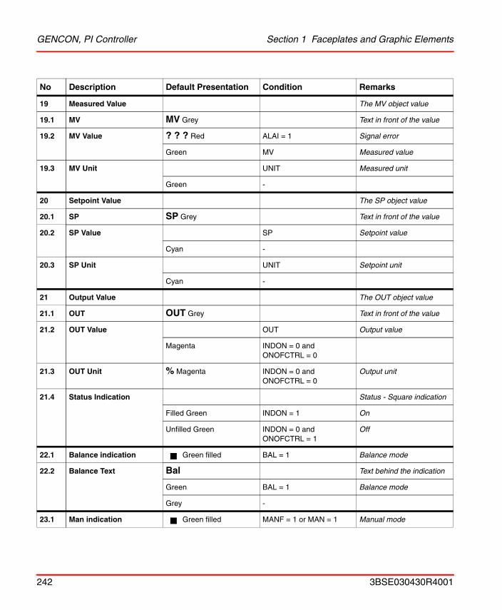
GENCON, PI Controller Section 1 Faceplates and Graphic Elements
19 Measured Value The MV object value
19.1 MV MV Grey Text in front of the value
19.2 MV Value ? ? ? Red ALAI = 1 Signal error
Green MV Measured value
19.3 MV Unit UNIT Measured unit
Green -
20 Setpoint Value The SP object value
20.1 SP SP Grey Text in front of the value
20.2 SP Value SP Setpoint value
Cyan -
20.3 SP Unit UNIT Setpoint unit
Cyan -
21 Output Value The OUT object value
21.1 OUT OUT Grey Text in front of the value
21.2 OUT Value OUT Output value
Magenta INDON = 0 and ONOFCTRL = 0
21.3 OUT Unit % Magenta INDON = 0 and ONOFCTRL = 0
Output unit
21.4 Status Indication Status - Square indication
Filled Green INDON = 1 On
Unfilled Green INDON = 0 and ONOFCTRL = 1
Off
22.1 Balance indication Green filled BAL = 1 Balance mode
22.2 Balance Text Bal Text behind the indication
Green BAL = 1 Balance mode
Grey -
23.1 Man indication Green filled MANF = 1 or MAN = 1 Manual mode
No Description Default Presentation Condition Remarks
242 3BSE030430R4001
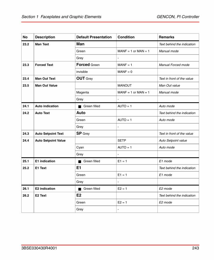
Section 1 Faceplates and Graphic Elements GENCON, PI Controller
23.2 Man Text Man Text behind the indication
Green MANF = 1 or MAN = 1 Manual mode
Grey -
23.3 Forced Text Forced Green MANF = 1 Manual Forced mode
invisible MANF = 0
23.4 Man Out Text OUT Grey Text in front of the value
23.5 Man Out Value MANOUT Man Out value
Magenta MANF = 1 or MAN = 1 Manual mode
Grey -
24.1 Auto indication Green filled AUTO = 1 Auto mode
24.2 Auto Text Auto Text behind the indication
Green AUTO = 1 Auto mode
Grey -
24.3 Auto Setpoint Text SP Grey Text in front of the value
24.4 Auto Setpoint Value SETP Auto Setpoint value
Cyan AUTO = 1 Auto mode
Grey -
25.1 E1 indication Green filled E1 = 1 E1 mode
25.2 E1 Text E1 Text behind the indication
Green E1 = 1 E1 mode
Grey -
26.1 E2 indication Green filled E2 = 1 E2 mode
26.2 E2 Text E2 Text behind the indication
Green E2 = 1 E2 mode
Grey -
No Description Default Presentation Condition Remarks
3BSE030430R4001 243
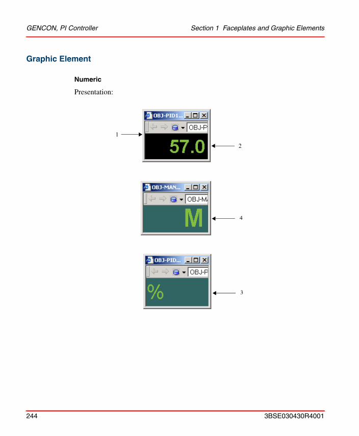
GENCON, PI Controller Section 1 Faceplates and Graphic Elements
Graphic Element
Numeric
Presentation:
2
1
4
3
244 3BSE030430R4001
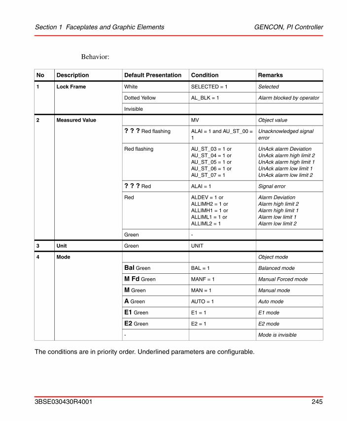
Section 1 Faceplates and Graphic Elements GENCON, PI Controller
Behavior:
The conditions are in priority order. Underlined parameters are configurable.
No Description Default Presentation Condition Remarks
1 Lock Frame White SELECTED = 1 Selected
Dotted Yellow AL_BLK = 1 Alarm blocked by operator
Invisible
2 Measured Value MV Object value
? ? ? Red flashing ALAI = 1 and AU_ST_00 = 1
Unacknowledged signal error
Red flashing AU_ST_03 = 1 orAU_ST_04 = 1 orAU_ST_05 = 1 or AU_ST_06 = 1 or AU_ST_07 = 1
UnAck alarm Deviation UnAck alarm high limit 2UnAck alarm high limit 1UnAck alarm low limit 1UnAck alarm low limit 2
? ? ? Red ALAI = 1 Signal error
Red ALDEV = 1 orALLIMH2 = 1 orALLIMH1 = 1 orALLIML1 = 1 orALLIML2 = 1
Alarm Deviation Alarm high limit 2Alarm high limit 1Alarm low limit 1Alarm low limit 2
Green -
3 Unit Green UNIT
4 Mode Object mode
Bal Green BAL = 1 Balanced mode
M Fd Green MANF = 1 Manual Forced mode
M Green MAN = 1 Manual mode
A Green AUTO = 1 Auto mode
E1 Green E1 = 1 E1 mode
E2 Green E2 = 1 E2 mode
- Mode is invisible
3BSE030430R4001 245
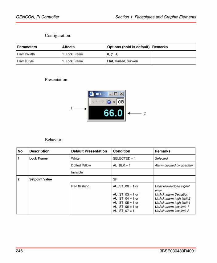
GENCON, PI Controller Section 1 Faceplates and Graphic Elements
Configuration:
Presentation:
Behavior:
Parameters Affects Options (bold is default) Remarks
FrameWidth 1. Lock Frame 0, (1..4)
FrameStyle 1. Lock Frame Flat, Raised, Sunken
No Description Default Presentation Condition Remarks
1 Lock Frame White SELECTED = 1 Selected
Dotted Yellow AL_BLK = 1 Alarm blocked by operator
Invisible
2 Setpoint Value SP
Red flashing AU_ST_00 = 1 or
AU_ST_03 = 1 orAU_ST_04 = 1 orAU_ST_05 = 1 or AU_ST_06 = 1 or AU_ST_07 = 1
Unacknowledged signal errorUnAck alarm Deviation UnAck alarm high limit 2UnAck alarm high limit 1UnAck alarm low limit 1UnAck alarm low limit 2
12
246 3BSE030430R4001
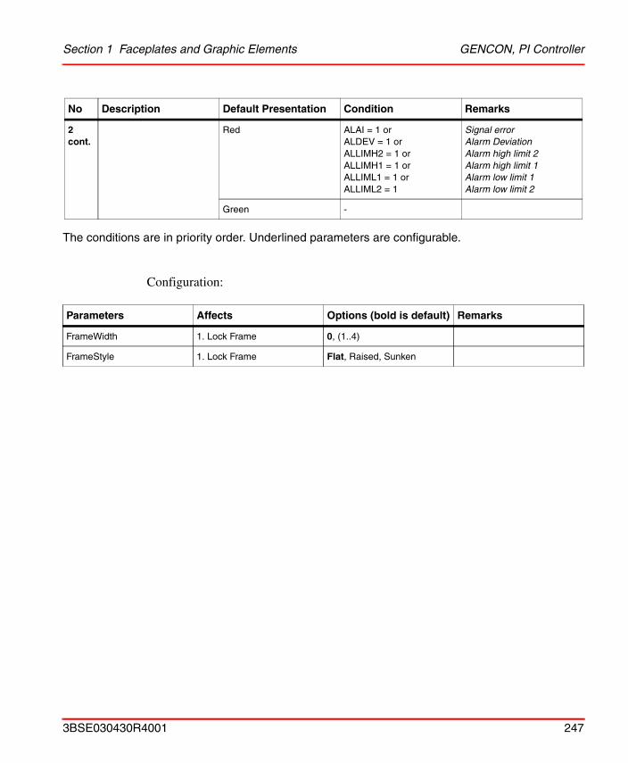
Section 1 Faceplates and Graphic Elements GENCON, PI Controller
The conditions are in priority order. Underlined parameters are configurable.
Configuration:
2 cont.
Red ALAI = 1 orALDEV = 1 orALLIMH2 = 1 orALLIMH1 = 1 orALLIML1 = 1 orALLIML2 = 1
Signal errorAlarm Deviation Alarm high limit 2Alarm high limit 1Alarm low limit 1Alarm low limit 2
Green -
Parameters Affects Options (bold is default) Remarks
FrameWidth 1. Lock Frame 0, (1..4)
FrameStyle 1. Lock Frame Flat, Raised, Sunken
No Description Default Presentation Condition Remarks
3BSE030430R4001 247
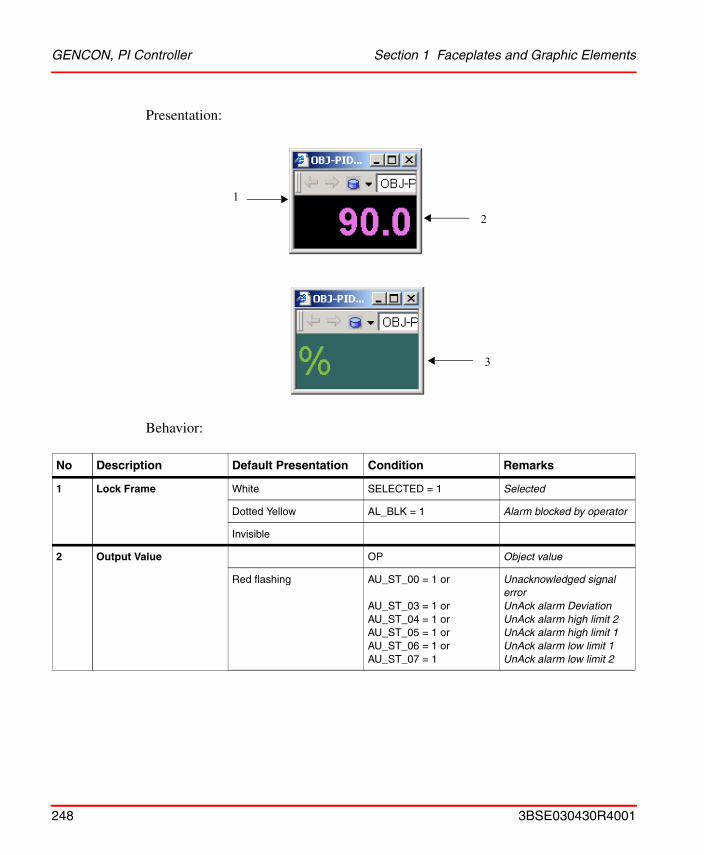
GENCON, PI Controller Section 1 Faceplates and Graphic Elements
Presentation:
Behavior:
No Description Default Presentation Condition Remarks
1 Lock Frame White SELECTED = 1 Selected
Dotted Yellow AL_BLK = 1 Alarm blocked by operator
Invisible
2 Output Value OP Object value
Red flashing AU_ST_00 = 1 or
AU_ST_03 = 1 orAU_ST_04 = 1 orAU_ST_05 = 1 or AU_ST_06 = 1 or AU_ST_07 = 1
Unacknowledged signal errorUnAck alarm Deviation UnAck alarm high limit 2UnAck alarm high limit 1UnAck alarm low limit 1UnAck alarm low limit 2
1
2
3
248 3BSE030430R4001
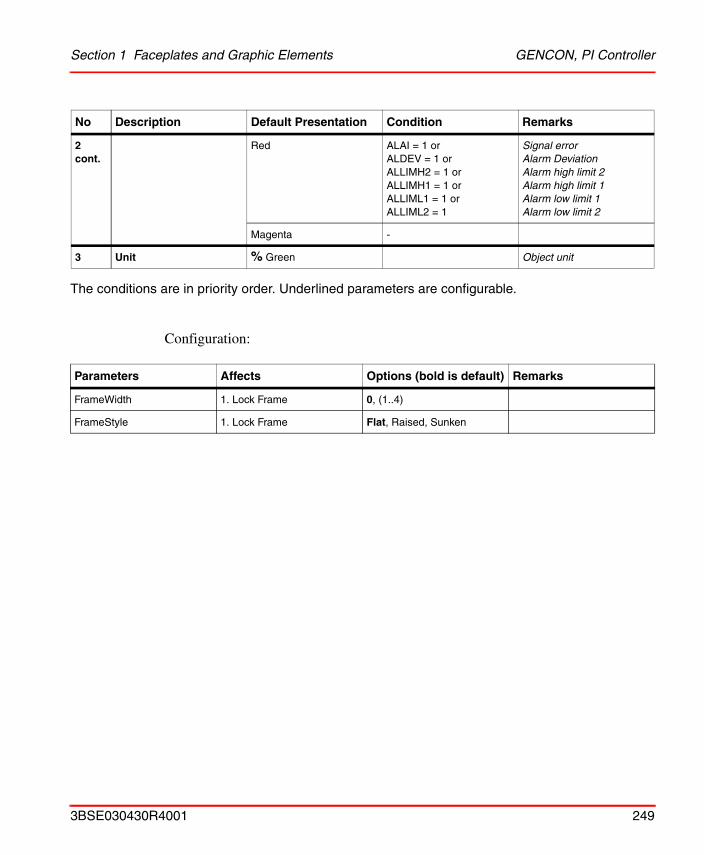
Section 1 Faceplates and Graphic Elements GENCON, PI Controller
The conditions are in priority order. Underlined parameters are configurable.
Configuration:
2 cont.
Red ALAI = 1 orALDEV = 1 orALLIMH2 = 1 orALLIMH1 = 1 orALLIML1 = 1 orALLIML2 = 1
Signal errorAlarm Deviation Alarm high limit 2Alarm high limit 1Alarm low limit 1Alarm low limit 2
Magenta -
3 Unit % Green Object unit
Parameters Affects Options (bold is default) Remarks
FrameWidth 1. Lock Frame 0, (1..4)
FrameStyle 1. Lock Frame Flat, Raised, Sunken
No Description Default Presentation Condition Remarks
3BSE030430R4001 249
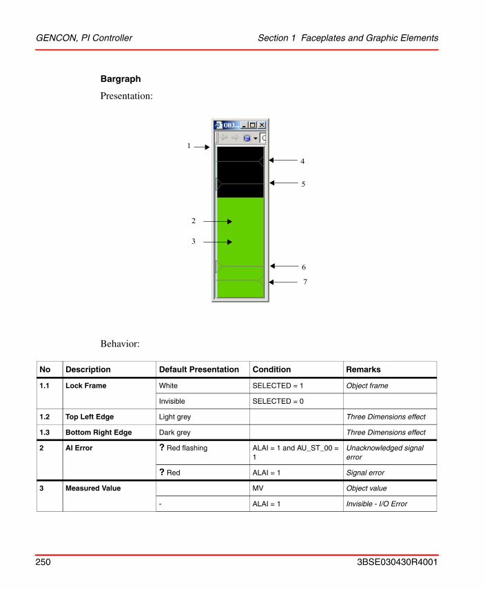
GENCON, PI Controller Section 1 Faceplates and Graphic Elements
Bargraph
Presentation:
Behavior:
No Description Default Presentation Condition Remarks
1.1 Lock Frame White SELECTED = 1 Object frame
Invisible SELECTED = 0
1.2 Top Left Edge Light grey Three Dimensions effect
1.3 Bottom Right Edge Dark grey Three Dimensions effect
2 AI Error ? Red flashing ALAI = 1 and AU_ST_00 = 1
Unacknowledged signal error
? Red ALAI = 1 Signal error
3 Measured Value MV Object value
- ALAI = 1 Invisible - I/O Error
1
2
4
7
5
6
3
250 3BSE030430R4001
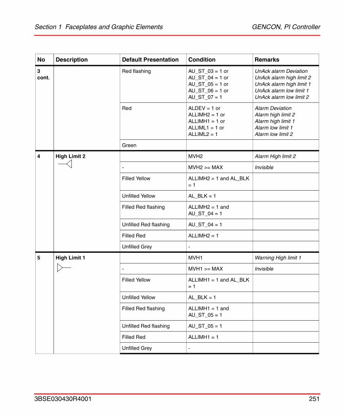
Section 1 Faceplates and Graphic Elements GENCON, PI Controller
3 cont.
Red flashing AU_ST_03 = 1 orAU_ST_04 = 1 orAU_ST_05 = 1 or AU_ST_06 = 1 or AU_ST_07 = 1
UnAck alarm Deviation UnAck alarm high limit 2UnAck alarm high limit 1UnAck alarm low limit 1UnAck alarm low limit 2
Red ALDEV = 1 orALLIMH2 = 1 orALLIMH1 = 1 orALLIML1 = 1 orALLIML2 = 1
Alarm Deviation Alarm high limit 2Alarm high limit 1Alarm low limit 1Alarm low limit 2
Green
4 High Limit 2 MVH2 Alarm High limit 2
- MVH2 >= MAX Invisible
Filled Yellow ALLIMH2 = 1 and AL_BLK = 1
Unfilled Yellow AL_BLK = 1
Filled Red flashing ALLIMH2 = 1 and AU_ST_04 = 1
Unfilled Red flashing AU_ST_04 = 1
Filled Red ALLIMH2 = 1
Unfilled Grey -
5 High Limit 1 MVH1 Warning High limit 1
- MVH1 >= MAX Invisible
Filled Yellow ALLIMH1 = 1 and AL_BLK = 1
Unfilled Yellow AL_BLK = 1
Filled Red flashing ALLIMH1 = 1 and AU_ST_05 = 1
Unfilled Red flashing AU_ST_05 = 1
Filled Red ALLIMH1 = 1
Unfilled Grey -
No Description Default Presentation Condition Remarks
3BSE030430R4001 251
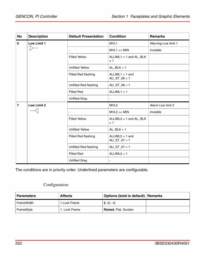
GENCON, PI Controller Section 1 Faceplates and Graphic Elements
The conditions are in priority order. Underlined parameters are configurable.
Configuration:
6 Low Limit 1 MVL1 Warning Low limit 1
- MVL1 <= MIN Invisible
Filled Yellow ALLIML1 = 1 and AL_BLK = 1
Unfilled Yellow AL_BLK = 1
Filled Red flashing ALLIML1 = 1 and AU_ST_06 = 1
Unfilled Red flashing AU_ST_06 = 1
Filled Red ALLIML1 = 1
Unfilled Grey -
7 Low Limit 2 MVL2 Alarm Low limit 2
- MVL2 <= MIN Invisible
Filled Yellow ALLIML2 = 1 and AL_BLK = 1
Unfilled Yellow AL_BLK = 1
Filled Red flashing ALLIML2 = 1 and AU_ST_07 = 1
Unfilled Red flashing AU_ST_07 = 1
Filled Red ALLIML2 = 1
Unfilled Grey -
Parameters Affects Options (bold is default) Remarks
FrameWidth 1 Lock Frame 3, (0...4)
FrameStyle 1. Lock Frame Raised, Flat, Sunken
No Description Default Presentation Condition Remarks
252 3BSE030430R4001
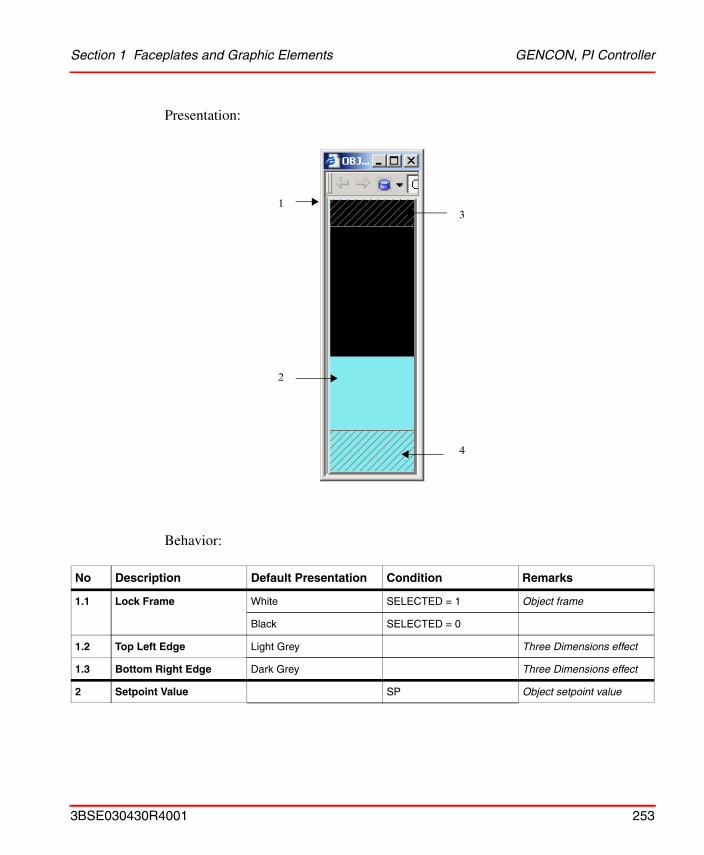
Section 1 Faceplates and Graphic Elements GENCON, PI Controller
Presentation:
Behavior:
No Description Default Presentation Condition Remarks
1.1 Lock Frame White SELECTED = 1 Object frame
Black SELECTED = 0
1.2 Top Left Edge Light Grey Three Dimensions effect
1.3 Bottom Right Edge Dark Grey Three Dimensions effect
2 Setpoint Value SP Object setpoint value
1
2
3
4
3BSE030430R4001 253
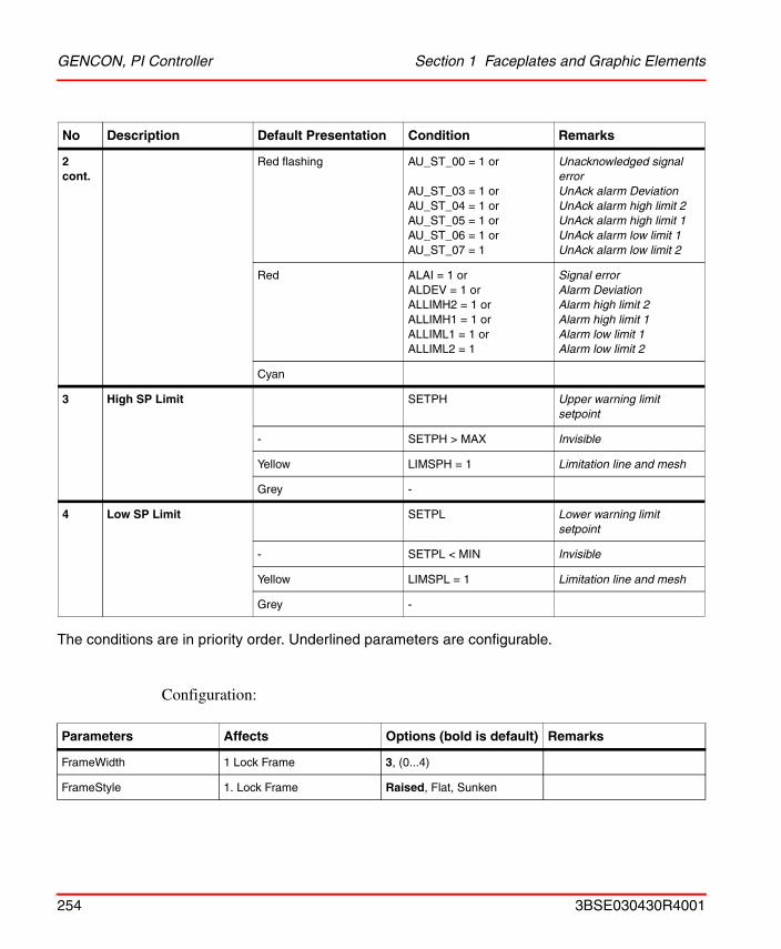
GENCON, PI Controller Section 1 Faceplates and Graphic Elements
The conditions are in priority order. Underlined parameters are configurable.
Configuration:
2 cont.
Red flashing AU_ST_00 = 1 or
AU_ST_03 = 1 orAU_ST_04 = 1 orAU_ST_05 = 1 or AU_ST_06 = 1 or AU_ST_07 = 1
Unacknowledged signal errorUnAck alarm Deviation UnAck alarm high limit 2UnAck alarm high limit 1UnAck alarm low limit 1UnAck alarm low limit 2
Red ALAI = 1 orALDEV = 1 orALLIMH2 = 1 orALLIMH1 = 1 orALLIML1 = 1 orALLIML2 = 1
Signal errorAlarm Deviation Alarm high limit 2Alarm high limit 1Alarm low limit 1Alarm low limit 2
Cyan
3 High SP Limit SETPH Upper warning limit setpoint
- SETPH > MAX Invisible
Yellow LIMSPH = 1 Limitation line and mesh
Grey -
4 Low SP Limit SETPL Lower warning limit setpoint
- SETPL < MIN Invisible
Yellow LIMSPL = 1 Limitation line and mesh
Grey -
Parameters Affects Options (bold is default) Remarks
FrameWidth 1 Lock Frame 3, (0...4)
FrameStyle 1. Lock Frame Raised, Flat, Sunken
No Description Default Presentation Condition Remarks
254 3BSE030430R4001
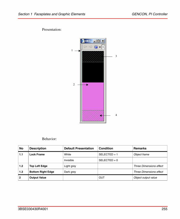
Section 1 Faceplates and Graphic Elements GENCON, PI Controller
Presentation:
Behavior:
No Description Default Presentation Condition Remarks
1.1 Lock Frame White SELECTED = 1 Object frame
Invisible SELECTED = 0
1.2 Top Left Edge Light grey Three Dimensions effect
1.3 Bottom Right Edge Dark grey Three Dimensions effect
2 Output Value OUT Object output value
1
2
3
4
3BSE030430R4001 255
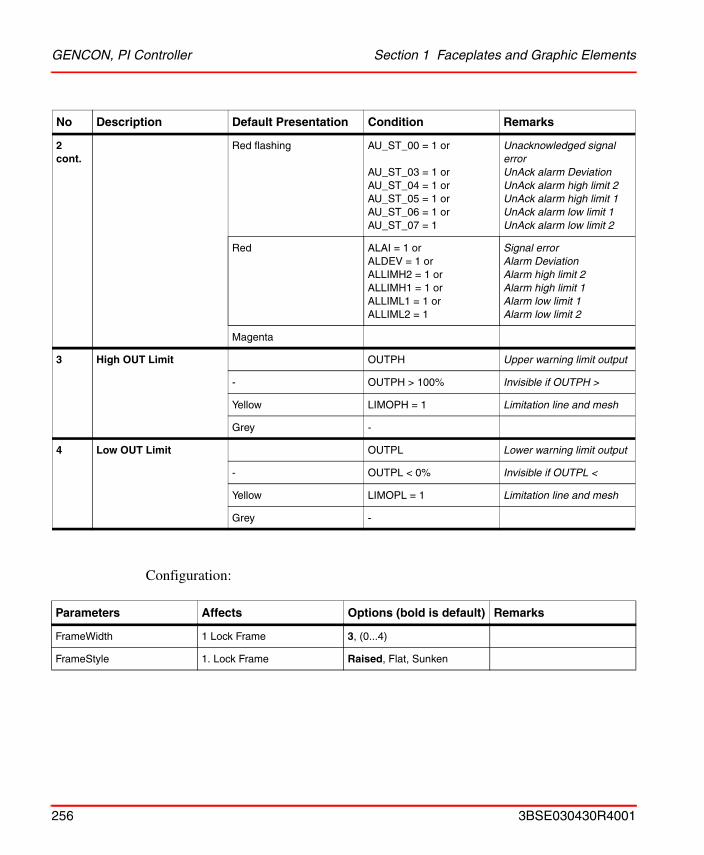
GENCON, PI Controller Section 1 Faceplates and Graphic Elements
Configuration:
2 cont.
Red flashing AU_ST_00 = 1 or
AU_ST_03 = 1 orAU_ST_04 = 1 orAU_ST_05 = 1 or AU_ST_06 = 1 or AU_ST_07 = 1
Unacknowledged signal errorUnAck alarm Deviation UnAck alarm high limit 2UnAck alarm high limit 1UnAck alarm low limit 1UnAck alarm low limit 2
Red ALAI = 1 orALDEV = 1 orALLIMH2 = 1 orALLIMH1 = 1 orALLIML1 = 1 orALLIML2 = 1
Signal errorAlarm Deviation Alarm high limit 2Alarm high limit 1Alarm low limit 1Alarm low limit 2
Magenta
3 High OUT Limit OUTPH Upper warning limit output
- OUTPH > 100% Invisible if OUTPH >
Yellow LIMOPH = 1 Limitation line and mesh
Grey -
4 Low OUT Limit OUTPL Lower warning limit output
- OUTPL < 0% Invisible if OUTPL <
Yellow LIMOPL = 1 Limitation line and mesh
Grey -
Parameters Affects Options (bold is default) Remarks
FrameWidth 1 Lock Frame 3, (0...4)
FrameStyle 1. Lock Frame Raised, Flat, Sunken
No Description Default Presentation Condition Remarks
256 3BSE030430R4001
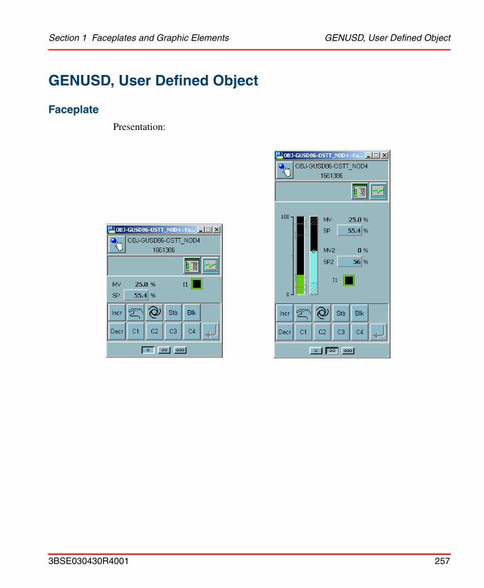
Section 1 Faceplates and Graphic Elements GENUSD, User Defined Object
GENUSD, User Defined Object
Faceplate
Presentation:
3BSE030430R4001 257
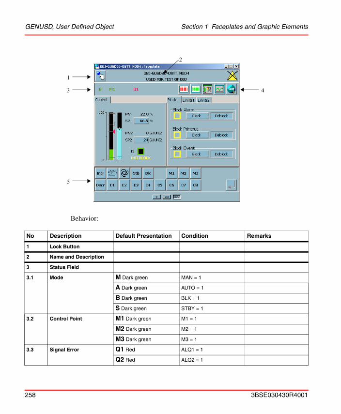
GENUSD, User Defined Object Section 1 Faceplates and Graphic Elements
Behavior:
No Description Default Presentation Condition Remarks
1 Lock Button
2 Name and Description
3 Status Field
3.1 Mode M Dark green MAN = 1
A Dark green AUTO = 1
B Dark green BLK = 1
S Dark green STBY = 1
3.2 Control Point M1 Dark green M1 = 1
M2 Dark green M2 = 1
M3 Dark green M3 = 1
3.3 Signal Error Q1 Red ALQ1 = 1
Q2 Red ALQ2 = 1
1
3
5
4
2
258 3BSE030430R4001
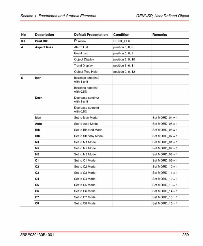
Section 1 Faceplates and Graphic Elements GENUSD, User Defined Object
3.4 Print Blk P Yellow PRINT_BLK
4 Aspect links Alarm List position 0, 0, 8
Event List position 0, 0, 9
Object Display position 5, 5, 10
Trend Display position 6, 6, 11
Object Type Help position 0, 0, 12
5 Incr Increase setpoint2with 1 unit
Increase setpoint with 0,5%
Decr Decrease setoint2with 1 unit
Decrease setpoint with 0,5%
Man Set to Man Mode Set MORD_04 = 1
Auto Set to Auto Mode Set MORD_05 = 1
Blk Set to Blocked Mode Set MORD_06 = 1
Stb Set to Standby Mode Set MORD_07 = 1
M1 Set to M1 Mode Set MORD_01 = 1
M2 Set to M2 Mode Set MORD_02 = 1
M3 Set to M3 Mode Set MORD_03 = 1
C1 Set to C1 Mode Set MORD_09 = 1
C2 Set to C2 Mode Set MORD_10 = 1
C3 Set to C3 Mode Set MORD_11 = 1
C4 Set to C4 Mode Set MORD_12 = 1
C5 Set to C5 Mode Set MORD_13 = 1
C6 Set to C6 Mode Set MORD_14 = 1
C7 Set to C7 Mode Set MORD_15 = 1
C8 Set to C8 Mode Set MORD_16 = 1
No Description Default Presentation Condition Remarks
3BSE030430R4001 259
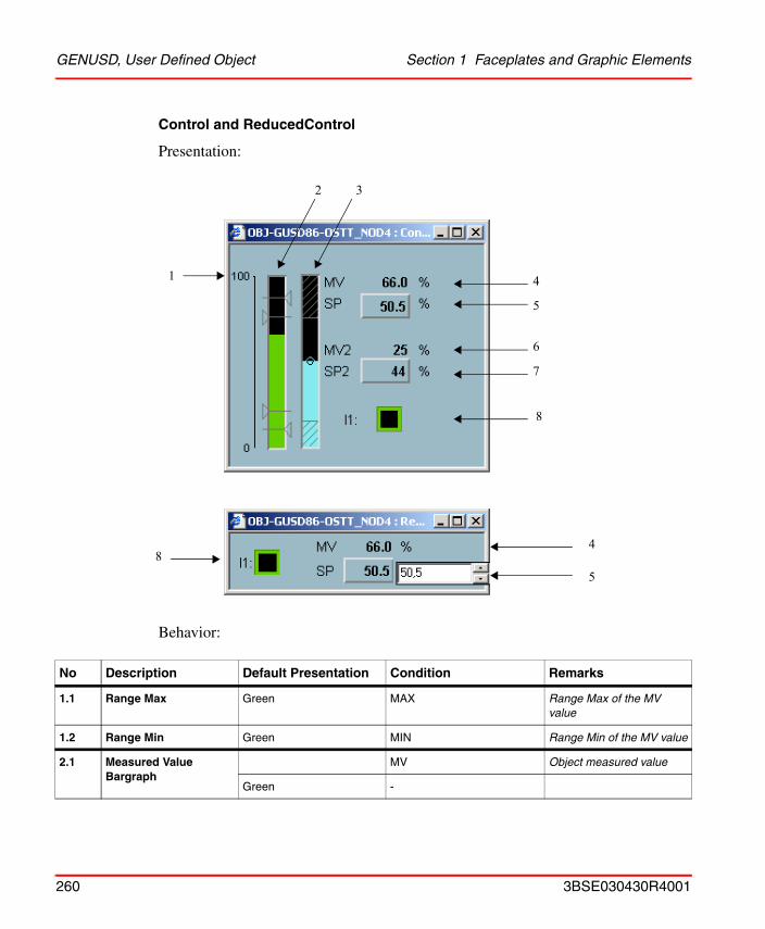
GENUSD, User Defined Object Section 1 Faceplates and Graphic Elements
Control and ReducedControl
Presentation:
Behavior:
No Description Default Presentation Condition Remarks
1.1 Range Max Green MAX Range Max of the MV value
1.2 Range Min Green MIN Range Min of the MV value
2.1 Measured Value Bargraph
MV Object measured value
Green -
1 4
5
6
7
2 3
8
84
5
260 3BSE030430R4001
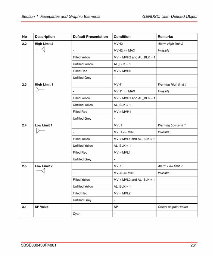
Section 1 Faceplates and Graphic Elements GENUSD, User Defined Object
2.2 High Limit 2 MVH2 Alarm High limit 2
- MVH2 >= MAX Invisible
Filled Yellow MV > MVH2 and AL_BLK = 1
Unfilled Yellow AL_BLK = 1
Filled Red MV > MVH2
Unfilled Grey -
2.3 High Limit 1 MVH1 Warning High limit 1
- MVH1 >= MAX Invisible
Filled Yellow MV > MVH1 and AL_BLK = 1
Unfilled Yellow AL_BLK = 1
Filled Red MV > MVH1
Unfilled Grey -
2.4 Low Limit 1 MVL1 Warning Low limit 1
- MVL1 <= MIN Invisible
Filled Yellow MV < MVL1 and AL_BLK = 1
Unfilled Yellow AL_BLK = 1
Filled Red MV < MVL1
Unfilled Grey -
2.5 Low Limit 2 MVL2 Alarm Low limit 2
- MVL2 <= MIN Invisible
Filled Yellow MV < MVL2 and AL_BLK = 1
Unfilled Yellow AL_BLK = 1
Filled Red MV < MVL2
Unfilled Grey -
3.1 SP Value SP Object setpoint value
Cyan -
No Description Default Presentation Condition Remarks
3BSE030430R4001 261
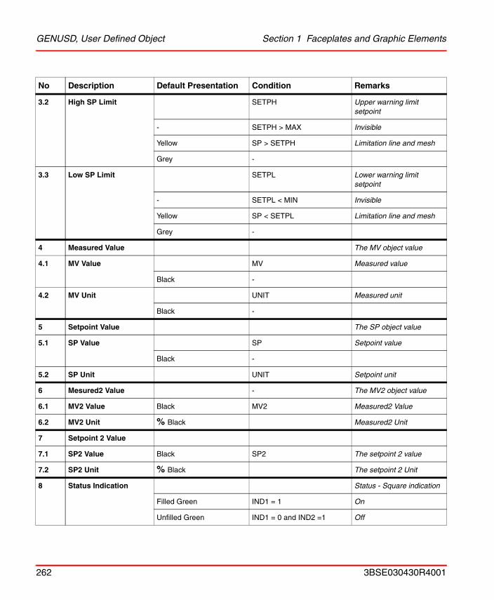
GENUSD, User Defined Object Section 1 Faceplates and Graphic Elements
3.2 High SP Limit SETPH Upper warning limit setpoint
- SETPH > MAX Invisible
Yellow SP > SETPH Limitation line and mesh
Grey -
3.3 Low SP Limit SETPL Lower warning limit setpoint
- SETPL < MIN Invisible
Yellow SP < SETPL Limitation line and mesh
Grey -
4 Measured Value The MV object value
4.1 MV Value MV Measured value
Black -
4.2 MV Unit UNIT Measured unit
Black -
5 Setpoint Value The SP object value
5.1 SP Value SP Setpoint value
Black -
5.2 SP Unit UNIT Setpoint unit
6 Mesured2 Value - The MV2 object value
6.1 MV2 Value Black MV2 Measured2 Value
6.2 MV2 Unit % Black Measured2 Unit
7 Setpoint 2 Value
7.1 SP2 Value Black SP2 The setpoint 2 value
7.2 SP2 Unit % Black The setpoint 2 Unit
8 Status Indication Status - Square indication
Filled Green IND1 = 1 On
Unfilled Green IND1 = 0 and IND2 =1 Off
No Description Default Presentation Condition Remarks
262 3BSE030430R4001
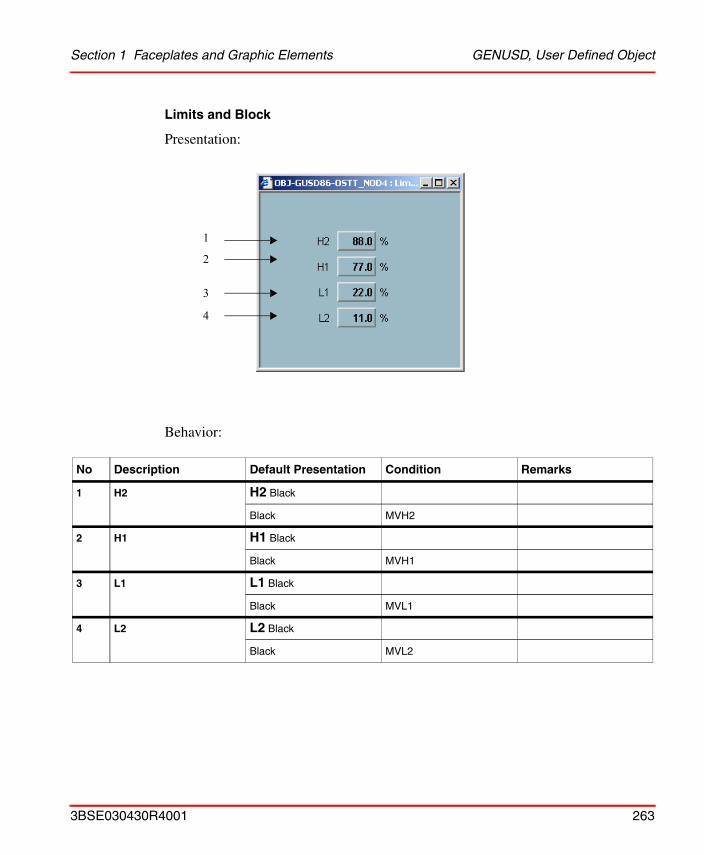
Section 1 Faceplates and Graphic Elements GENUSD, User Defined Object
Limits and Block
Presentation:
Behavior:
No Description Default Presentation Condition Remarks
1 H2 H2 Black
Black MVH2
2 H1 H1 Black
Black MVH1
3 L1 L1 Black
Black MVL1
4 L2 L2 Black
Black MVL2
1
2
3
4
3BSE030430R4001 263
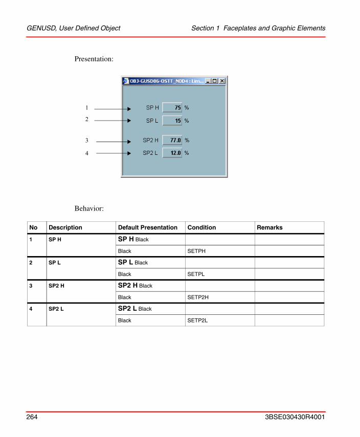
GENUSD, User Defined Object Section 1 Faceplates and Graphic Elements
Presentation:
Behavior:
No Description Default Presentation Condition Remarks
1 SP H SP H Black
Black SETPH
2 SP L SP L Black
Black SETPL
3 SP2 H SP2 H Black
Black SETP2H
4 SP2 L SP2 L Black
Black SETP2L
1
2
4
3
264 3BSE030430R4001
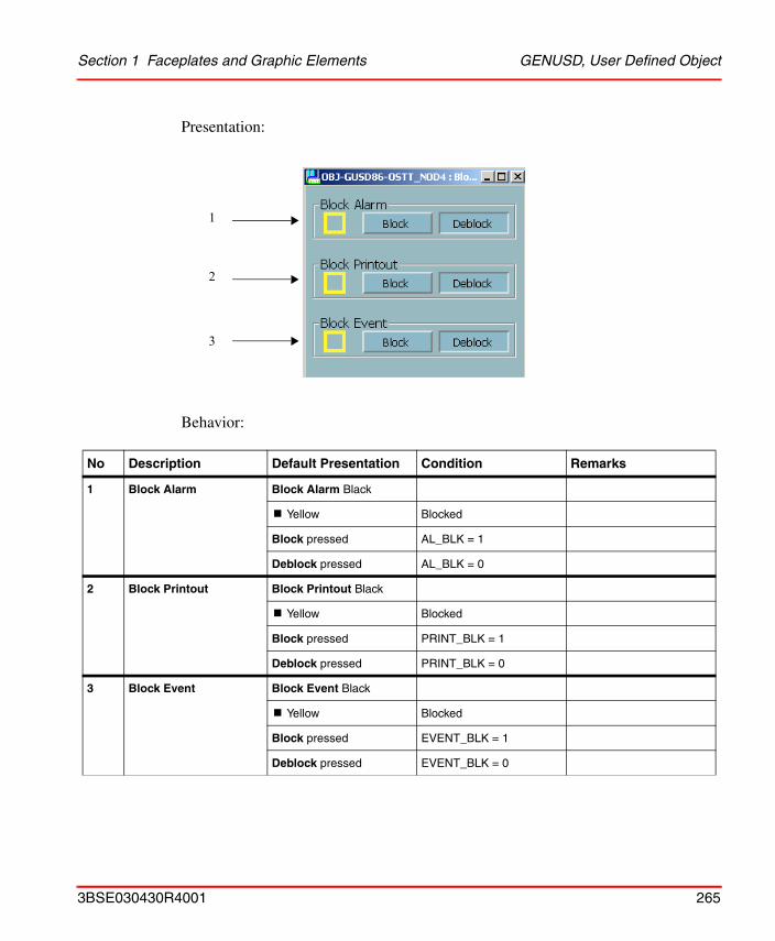
Section 1 Faceplates and Graphic Elements GENUSD, User Defined Object
Presentation:
Behavior:
No Description Default Presentation Condition Remarks
1 Block Alarm Block Alarm Black
! Yellow Blocked
Block pressed AL_BLK = 1
Deblock pressed AL_BLK = 0
2 Block Printout Block Printout Black
! Yellow Blocked
Block pressed PRINT_BLK = 1
Deblock pressed PRINT_BLK = 0
3 Block Event Block Event Black
! Yellow Blocked
Block pressed EVENT_BLK = 1
Deblock pressed EVENT_BLK = 0
1
2
3
3BSE030430R4001 265
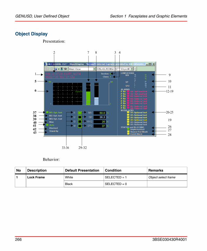
GENUSD, User Defined Object Section 1 Faceplates and Graphic Elements
Object Display
Presentation:
Behavior:
No Description Default Presentation Condition Remarks
1 Lock Frame White SELECTED = 1 Object select frame
Black SELECTED = 0
1
2 7
29-3233-36
10
19
28
9
4
1112-19
5
6
37
38
20-25
2726
383940414243
266 3BSE030430R4001
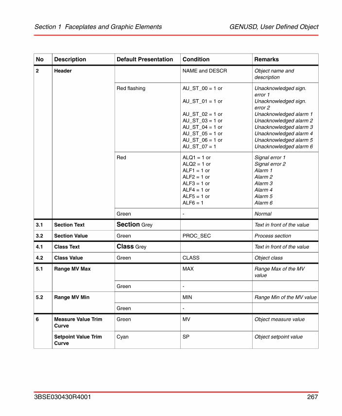
Section 1 Faceplates and Graphic Elements GENUSD, User Defined Object
2 Header NAME and DESCR Object name and description
Red flashing AU_ST_00 = 1 or
AU_ST_01 = 1 or
AU_ST_02 = 1 or AU_ST_03 = 1 orAU_ST_04 = 1 or AU_ST_05 = 1 or AU_ST_06 = 1 or AU_ST_07 = 1
Unacknowledged sign. error 1Unacknowledged sign. error 2Unacknowledged alarm 1Unacknowledged alarm 2Unacknowledged alarm 3Unacknowledged alarm 4Unacknowledged alarm 5Unacknowledged alarm 6
Red ALQ1 = 1 orALQ2 = 1 orALF1 = 1 orALF2 = 1 orALF3 = 1 orALF4 = 1 orALF5 = 1 orALF6 = 1
Signal error 1Signal error 2Alarm 1Alarm 2Alarm 3Alarm 4Alarm 5Alarm 6
Green - Normal
3.1 Section Text Section Grey Text in front of the value
3.2 Section Value Green PROC_SEC Process section
4.1 Class Text Class Grey Text in front of the value
4.2 Class Value Green CLASS Object class
5.1 Range MV Max MAX Range Max of the MV value
Green -
5.2 Range MV Min MIN Range Min of the MV value
Green -
6 Measure Value Trim Curve
Green MV Object measure value
Setpoint Value Trim Curve
Cyan SP Object setpoint value
No Description Default Presentation Condition Remarks
3BSE030430R4001 267
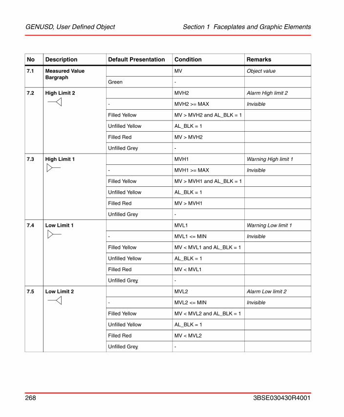
GENUSD, User Defined Object Section 1 Faceplates and Graphic Elements
7.1 Measured Value Bargraph
MV Object value
Green -
7.2 High Limit 2 MVH2 Alarm High limit 2
- MVH2 >= MAX Invisible
Filled Yellow MV > MVH2 and AL_BLK = 1
Unfilled Yellow AL_BLK = 1
Filled Red MV > MVH2
Unfilled Grey -
7.3 High Limit 1 MVH1 Warning High limit 1
- MVH1 >= MAX Invisible
Filled Yellow MV > MVH1 and AL_BLK = 1
Unfilled Yellow AL_BLK = 1
Filled Red MV > MVH1
Unfilled Grey -
7.4 Low Limit 1 MVL1 Warning Low limit 1
- MVL1 <= MIN Invisible
Filled Yellow MV < MVL1 and AL_BLK = 1
Unfilled Yellow AL_BLK = 1
Filled Red MV < MVL1
Unfilled Grey -
7.5 Low Limit 2 MVL2 Alarm Low limit 2
- MVL2 <= MIN Invisible
Filled Yellow MV < MVL2 and AL_BLK = 1
Unfilled Yellow AL_BLK = 1
Filled Red MV < MVL2
Unfilled Grey -
No Description Default Presentation Condition Remarks
268 3BSE030430R4001
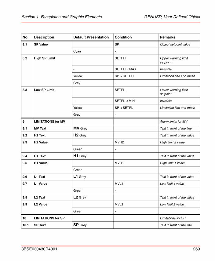
Section 1 Faceplates and Graphic Elements GENUSD, User Defined Object
8.1 SP Value SP Object setpoint value
Cyan -
8.2 High SP Limit SETPH Upper warning limit setpoint
- SETPH > MAX Invisible
Yellow SP > SETPH Limitation line and mesh
Grey -
8.3 Low SP Limit SETPL Lower warning limit setpoint
- SETPL < MIN Invisible
Yellow SP < SETPL Limitation line and mesh
Grey -
9 LIMITATIONS for MV Alarm limits for MV
9.1 MV Text MV Grey Text in front of the line
9.2 H2 Text H2 Grey Text in front of the value
9.3 H2 Value MVH2 High limit 2 value
Green -
9.4 H1 Text H1 Grey Text in front of the value
9.5 H1 Value MVH1 High limit 1 value
Green -
9.6 L1 Text L1 Grey Text in front of the value
9.7 L1 Value MVL1 Low limit 1 value
Green -
9.8 L2 Text L2 Grey Text in front of the value
9.9 L2 Value MVL2 Low limit 2 value
Green -
10 LIMITATIONS for SP Limitations for SP
10.1 SP Text SP Grey Text in front of the line
No Description Default Presentation Condition Remarks
3BSE030430R4001 269
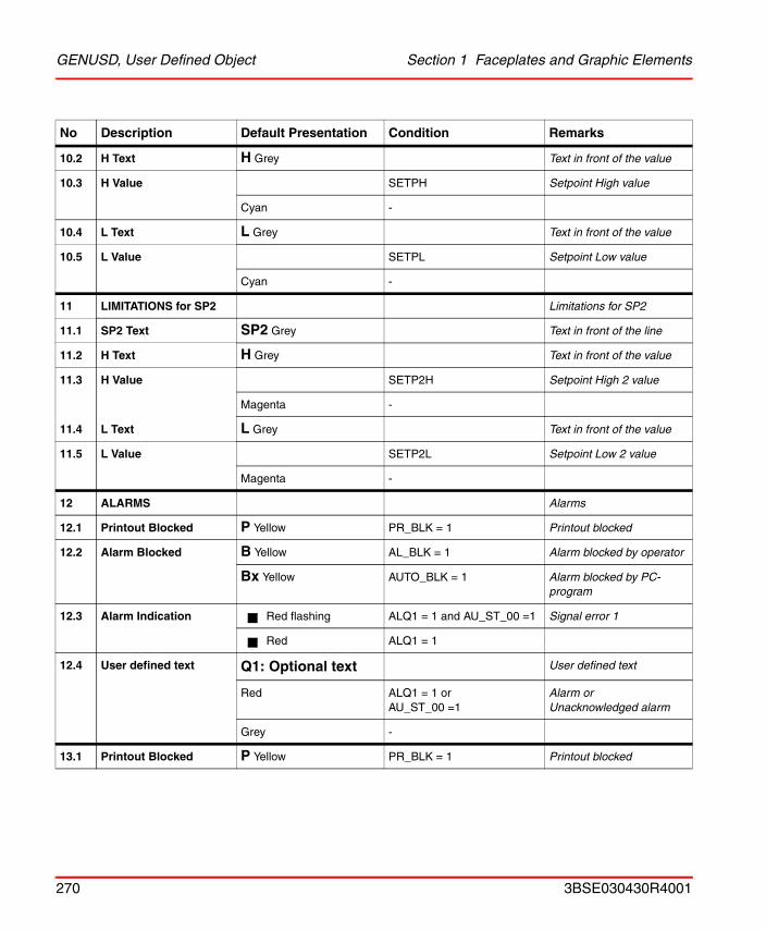
GENUSD, User Defined Object Section 1 Faceplates and Graphic Elements
10.2 H Text H Grey Text in front of the value
10.3 H Value SETPH Setpoint High value
Cyan -
10.4 L Text L Grey Text in front of the value
10.5 L Value SETPL Setpoint Low value
Cyan -
11 LIMITATIONS for SP2 Limitations for SP2
11.1 SP2 Text SP2 Grey Text in front of the line
11.2 H Text H Grey Text in front of the value
11.3 H Value SETP2H Setpoint High 2 value
Magenta -
11.4 L Text L Grey Text in front of the value
11.5 L Value SETP2L Setpoint Low 2 value
Magenta -
12 ALARMS Alarms
12.1 Printout Blocked P Yellow PR_BLK = 1 Printout blocked
12.2 Alarm Blocked B Yellow AL_BLK = 1 Alarm blocked by operator
Bx Yellow AUTO_BLK = 1 Alarm blocked by PC-program
12.3 Alarm Indication Red flashing ALQ1 = 1 and AU_ST_00 =1 Signal error 1
Red ALQ1 = 1
12.4 User defined text Q1: Optional text User defined text
Red ALQ1 = 1 orAU_ST_00 =1
Alarm or Unacknowledged alarm
Grey -
13.1 Printout Blocked P Yellow PR_BLK = 1 Printout blocked
No Description Default Presentation Condition Remarks
270 3BSE030430R4001
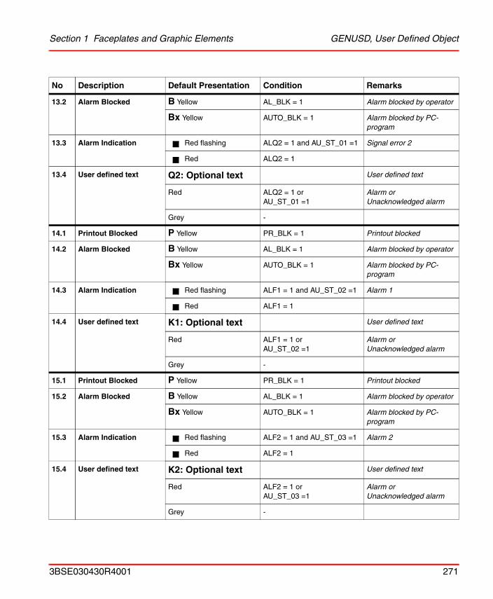
Section 1 Faceplates and Graphic Elements GENUSD, User Defined Object
13.2 Alarm Blocked B Yellow AL_BLK = 1 Alarm blocked by operator
Bx Yellow AUTO_BLK = 1 Alarm blocked by PC-program
13.3 Alarm Indication Red flashing ALQ2 = 1 and AU_ST_01 =1 Signal error 2
Red ALQ2 = 1
13.4 User defined text Q2: Optional text User defined text
Red ALQ2 = 1 orAU_ST_01 =1
Alarm orUnacknowledged alarm
Grey -
14.1 Printout Blocked P Yellow PR_BLK = 1 Printout blocked
14.2 Alarm Blocked B Yellow AL_BLK = 1 Alarm blocked by operator
Bx Yellow AUTO_BLK = 1 Alarm blocked by PC-program
14.3 Alarm Indication Red flashing ALF1 = 1 and AU_ST_02 =1 Alarm 1
Red ALF1 = 1
14.4 User defined text K1: Optional text User defined text
Red ALF1 = 1 orAU_ST_02 =1
Alarm orUnacknowledged alarm
Grey -
15.1 Printout Blocked P Yellow PR_BLK = 1 Printout blocked
15.2 Alarm Blocked B Yellow AL_BLK = 1 Alarm blocked by operator
Bx Yellow AUTO_BLK = 1 Alarm blocked by PC-program
15.3 Alarm Indication Red flashing ALF2 = 1 and AU_ST_03 =1 Alarm 2
Red ALF2 = 1
15.4 User defined text K2: Optional text User defined text
Red ALF2 = 1 orAU_ST_03 =1
Alarm orUnacknowledged alarm
Grey -
No Description Default Presentation Condition Remarks
3BSE030430R4001 271
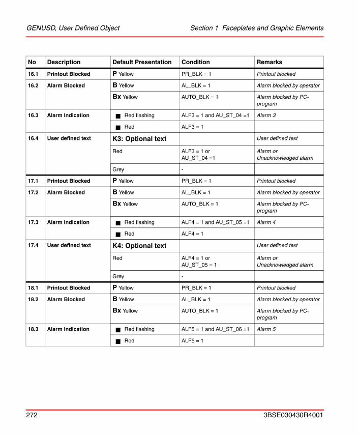
GENUSD, User Defined Object Section 1 Faceplates and Graphic Elements
16.1 Printout Blocked P Yellow PR_BLK = 1 Printout blocked
16.2 Alarm Blocked B Yellow AL_BLK = 1 Alarm blocked by operator
Bx Yellow AUTO_BLK = 1 Alarm blocked by PC-program
16.3 Alarm Indication Red flashing ALF3 = 1 and AU_ST_04 =1 Alarm 3
Red ALF3 = 1
16.4 User defined text K3: Optional text User defined text
Red ALF3 = 1 orAU_ST_04 =1
Alarm orUnacknowledged alarm
Grey -
17.1 Printout Blocked P Yellow PR_BLK = 1 Printout blocked
17.2 Alarm Blocked B Yellow AL_BLK = 1 Alarm blocked by operator
Bx Yellow AUTO_BLK = 1 Alarm blocked by PC-program
17.3 Alarm Indication Red flashing ALF4 = 1 and AU_ST_05 =1 Alarm 4
Red ALF4 = 1
17.4 User defined text K4: Optional text User defined text
Red ALF4 = 1 orAU_ST_05 = 1
Alarm orUnacknowledged alarm
Grey -
18.1 Printout Blocked P Yellow PR_BLK = 1 Printout blocked
18.2 Alarm Blocked B Yellow AL_BLK = 1 Alarm blocked by operator
Bx Yellow AUTO_BLK = 1 Alarm blocked by PC-program
18.3 Alarm Indication Red flashing ALF5 = 1 and AU_ST_06 =1 Alarm 5
Red ALF5 = 1
No Description Default Presentation Condition Remarks
272 3BSE030430R4001
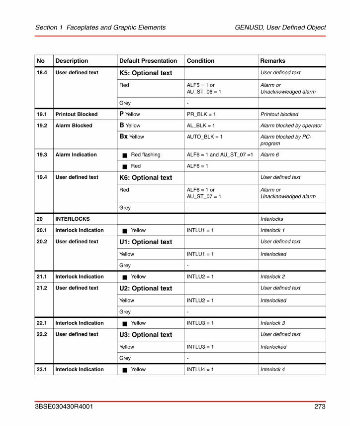
Section 1 Faceplates and Graphic Elements GENUSD, User Defined Object
18.4 User defined text K5: Optional text User defined text
Red ALF5 = 1 orAU_ST_06 = 1
Alarm orUnacknowledged alarm
Grey -
19.1 Printout Blocked P Yellow PR_BLK = 1 Printout blocked
19.2 Alarm Blocked B Yellow AL_BLK = 1 Alarm blocked by operator
Bx Yellow AUTO_BLK = 1 Alarm blocked by PC-program
19.3 Alarm Indication Red flashing ALF6 = 1 and AU_ST_07 =1 Alarm 6
Red ALF6 = 1
19.4 User defined text K6: Optional text User defined text
Red ALF6 = 1 orAU_ST_07 = 1
Alarm orUnacknowledged alarm
Grey -
20 INTERLOCKS Interlocks
20.1 Interlock Indication Yellow INTLU1 = 1 Interlock 1
20.2 User defined text U1: Optional text User defined text
Yellow INTLU1 = 1 Interlocked
Grey -
21.1 Interlock Indication Yellow INTLU2 = 1 Interlock 2
21.2 User defined text U2: Optional text User defined text
Yellow INTLU2 = 1 Interlocked
Grey -
22.1 Interlock Indication Yellow INTLU3 = 1 Interlock 3
22.2 User defined text U3: Optional text User defined text
Yellow INTLU3 = 1 Interlocked
Grey -
23.1 Interlock Indication Yellow INTLU4 = 1 Interlock 4
No Description Default Presentation Condition Remarks
3BSE030430R4001 273
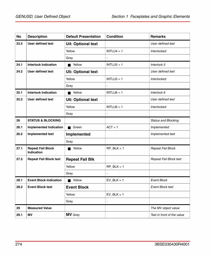
GENUSD, User Defined Object Section 1 Faceplates and Graphic Elements
23.2 User defined text U4: Optional text User defined text
Yellow INTLU4 = 1 Interlocked
Grey -
24.1 Interlock Indication Yellow INTLU5 = 1 Interlock 5
24.2 User defined text U5: Optional text User defined text
Yellow INTLU5 = 1 Interlocked
Grey -
25.1 Interlock Indication Yellow INTLU6 = 1 Interlock 6
25.2 User defined text U6: Optional text User defined text
Yellow INTLU6 = 1 Interlocked
Grey -
26 STATUS & BLOCKING Status and Blocking
26.1 Implemented Indication Green ACT = 1 Implemented
26.2 Implemented text Implemented Implemented text
Grey
27.1 Repeat Fail Block Indication
Yellow RP_BLK = 1 Repeat Fail Block
27.2 Repeat Fail Block text Repeat Fail Blk Repeat Fail Block text
Yellow RP_BLK = 1
Grey -
28.1 Event Block Indication Yellow EV_BLK = 1 Event Block
28.2 Event Block text Event Block Event Block text
Yellow EV_BLK = 1
Grey -
29 Measured Value The MV object value
29.1 MV MV Grey Text in front of the value
No Description Default Presentation Condition Remarks
274 3BSE030430R4001
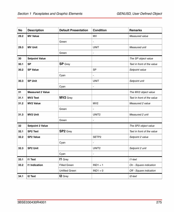
Section 1 Faceplates and Graphic Elements GENUSD, User Defined Object
29.2 MV Value MV Measured value
Green -
29.3 MV Unit UNIT Measured unit
Green -
30 Setpoint Value The SP object value
30.1 SP SP Grey Text in front of the value
30.2 SP Value SP Setpoint value
Cyan -
30.3 SP Unit UNIT Setpoint unit
Cyan -
31 Measured 2 Value The MV2 object value
31.1 MV2 Text MV2 Grey Text in front of the value
31.2 MV2 Value MV2 Measured 2 value
Green -
31.3 MV2 Unit UNIT2 Measured 2 unit
Green -
32 Setpoint 2 Value The SP2 object value
32.1 SP2 Text SP2 Grey Text in front of the value
32.2 SP2 Value SETP2 Setpoint 2 value
Cyan -
32.3 SP2 Unit UNIT2 Setpoint 2 unit
Cyan -
33.1 I1 Text I1 Grey I1-text
33.2 I1 Indication Filled Green IND1 = 1 On - Square indication
Unfilled Green IND1 = 0 Off - Square indication
34.1 I2 Text I2 Grey I2-text
No Description Default Presentation Condition Remarks
3BSE030430R4001 275
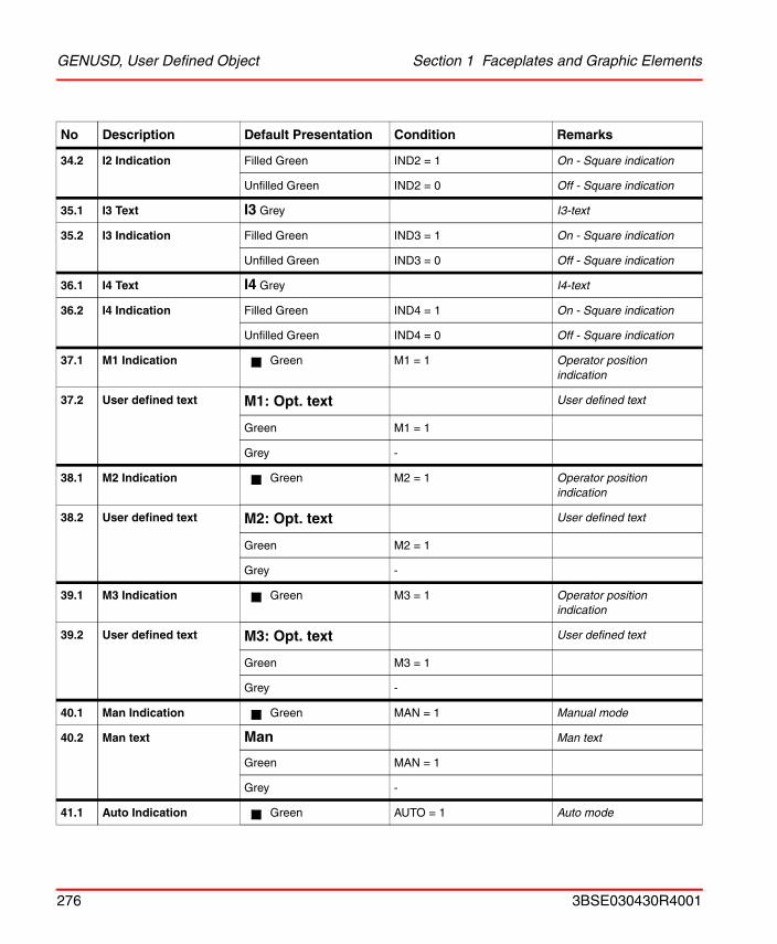
GENUSD, User Defined Object Section 1 Faceplates and Graphic Elements
34.2 I2 Indication Filled Green IND2 = 1 On - Square indication
Unfilled Green IND2 = 0 Off - Square indication
35.1 I3 Text I3 Grey I3-text
35.2 I3 Indication Filled Green IND3 = 1 On - Square indication
Unfilled Green IND3 = 0 Off - Square indication
36.1 I4 Text I4 Grey I4-text
36.2 I4 Indication Filled Green IND4 = 1 On - Square indication
Unfilled Green IND4 = 0 Off - Square indication
37.1 M1 Indication Green M1 = 1 Operator position indication
37.2 User defined text M1: Opt. text User defined text
Green M1 = 1
Grey -
38.1 M2 Indication Green M2 = 1 Operator position indication
38.2 User defined text M2: Opt. text User defined text
Green M2 = 1
Grey -
39.1 M3 Indication Green M3 = 1 Operator position indication
39.2 User defined text M3: Opt. text User defined text
Green M3 = 1
Grey -
40.1 Man Indication Green MAN = 1 Manual mode
40.2 Man text Man Man text
Green MAN = 1
Grey -
41.1 Auto Indication Green AUTO = 1 Auto mode
No Description Default Presentation Condition Remarks
276 3BSE030430R4001
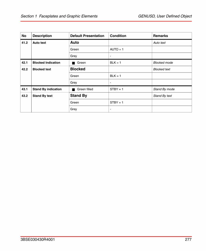
Section 1 Faceplates and Graphic Elements GENUSD, User Defined Object
41.2 Auto text Auto Auto text
Green AUTO = 1
Grey -
42.1 Blocked Indication Green BLK = 1 Blocked mode
42.2 Blocked text Blocked Blocked text
Green BLK = 1
Grey -
43.1 Stand By indication Green filled STBY = 1 Stand By mode
43.2 Stand By text Stand By Stand By text
Green STBY = 1
Grey -
No Description Default Presentation Condition Remarks
3BSE030430R4001 277
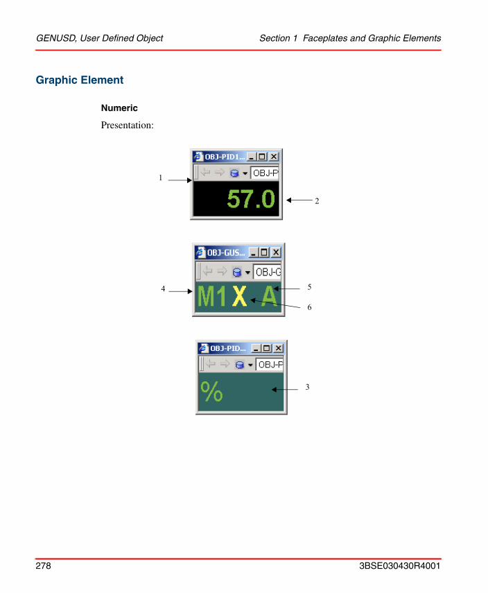
GENUSD, User Defined Object Section 1 Faceplates and Graphic Elements
Graphic Element
Numeric
Presentation:
2
1
6
54
3
278 3BSE030430R4001
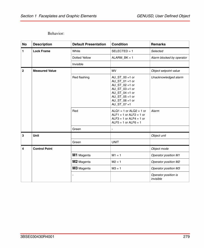
Section 1 Faceplates and Graphic Elements GENUSD, User Defined Object
Behavior:
No Description Default Presentation Condition Remarks
1 Lock Frame White SELECTED = 1 Selected
Dotted Yellow ALARM_BK = 1 Alarm blocked by operator
Invisible
2 Measured Value MV Object setpoint value
Red flashing AU_ST_00 =1 or AU_ST_01 =1 or AU_ST_02 =1 or AU_ST_03 =1 or AU_ST_04 =1 or AU_ST_05 =1 or AU_ST_06 =1 or AU_ST_07 =1
Unacknowledged alarm
Red ALQ1 = 1 or ALQ2 = 1 orALF1 = 1 or ALF2 = 1 orALF3 = 1 or ALF4 = 1 orALF5 = 1 or ALF6 = 1
Alarm
Green -
3 Unit Object unit
Green UNIT
4 Control Point Object mode
M1 Magenta M1 = 1 Operator position M1
M2 Magenta M2 = 1 Operator position M2
M3 Magenta M3 = 1 Operator position M3
- Operator position is invisible
3BSE030430R4001 279
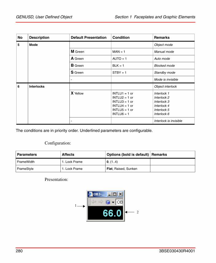
GENUSD, User Defined Object Section 1 Faceplates and Graphic Elements
The conditions are in priority order. Underlined parameters are configurable.
Configuration:
Presentation:
5 Mode Object mode
M Green MAN = 1 Manual mode
A Green AUTO = 1 Auto mode
B Green BLK = 1 Blocked mode
S Green STBY = 1 Standby mode
- Mode is invisible
6 Interlocks Object interlock
X Yellow INTLU1 = 1 orINTLU2 = 1 orINTLU3 = 1 orINTLU4 = 1 orINTLU5 = 1 orINTLU6 = 1
Interlock 1 Interlock 2Interlock 3Interlock 4Interlock 5Interlock 6
- Interlock is invisible
Parameters Affects Options (bold is default) Remarks
FrameWidth 1. Lock Frame 0, (1..4)
FrameStyle 1. Lock Frame Flat, Raised, Sunken
No Description Default Presentation Condition Remarks
1
2
280 3BSE030430R4001
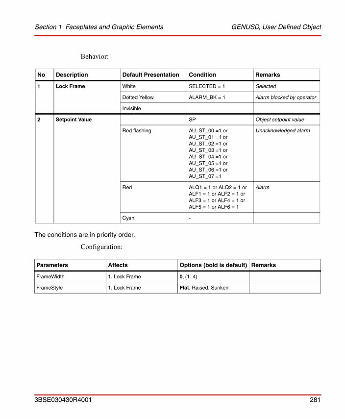
Section 1 Faceplates and Graphic Elements GENUSD, User Defined Object
Behavior:
The conditions are in priority order.
Configuration:
No Description Default Presentation Condition Remarks
1 Lock Frame White SELECTED = 1 Selected
Dotted Yellow ALARM_BK = 1 Alarm blocked by operator
Invisible
2 Setpoint Value SP Object setpoint value
Red flashing AU_ST_00 =1 or AU_ST_01 =1 or AU_ST_02 =1 or AU_ST_03 =1 or AU_ST_04 =1 or AU_ST_05 =1 or AU_ST_06 =1 or AU_ST_07 =1
Unacknowledged alarm
Red ALQ1 = 1 or ALQ2 = 1 orALF1 = 1 or ALF2 = 1 orALF3 = 1 or ALF4 = 1 orALF5 = 1 or ALF6 = 1
Alarm
Cyan -
Parameters Affects Options (bold is default) Remarks
FrameWidth 1. Lock Frame 0, (1..4)
FrameStyle 1. Lock Frame Flat, Raised, Sunken
3BSE030430R4001 281
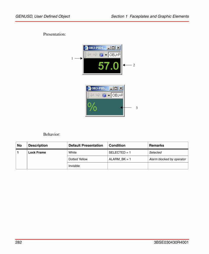
GENUSD, User Defined Object Section 1 Faceplates and Graphic Elements
Presentation:
Behavior:
No Description Default Presentation Condition Remarks
1 Lock Frame White SELECTED = 1 Selected
Dotted Yellow ALARM_BK = 1 Alarm blocked by operator
Invisible
1
2
3
282 3BSE030430R4001
Section 1 Faceplates and Graphic Elements GENUSD, User Defined Object
The conditions are in priority order. Underlined parameters are configurable.
Configuration:
2 MV2 Value MV2 Measured 2 value
Red flashing AU_ST_00 =1 or AU_ST_01 =1 or AU_ST_02 =1 or AU_ST_03 =1 or AU_ST_04 =1 or AU_ST_05 =1 or AU_ST_06 =1 or AU_ST_07 =1
Unacknowledged alarm
Red ALQ1 = 1 or ALQ2 = 1 orALF1 = 1 or ALF2 = 1 orALF3 = 1 or ALF4 = 1 orALF5 = 1 or ALF6 = 1
Alarm
Cyan -
3 Unit Object unit
Green UNIT2 Measured 2 unit
Parameters Affects Options (bold is default) Remarks
FrameWidth 1. Lock Frame 0, (1..4)
FrameStyle 1. Lock Frame Flat, Raised, Sunken
No Description Default Presentation Condition Remarks
3BSE030430R4001 283
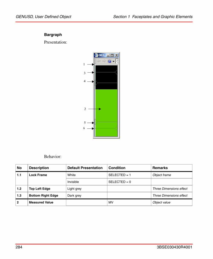
GENUSD, User Defined Object Section 1 Faceplates and Graphic Elements
Bargraph
Presentation:
Behavior:
No Description Default Presentation Condition Remarks
1.1 Lock Frame White SELECTED = 1 Object frame
Invisible SELECTED = 0
1.2 Top Left Edge Light grey Three Dimensions effect
1.3 Bottom Right Edge Dark grey Three Dimensions effect
2 Measured Value MV Object value
1
2
5
6
3
4
284 3BSE030430R4001
Section 1 Faceplates and Graphic Elements GENUSD, User Defined Object
2 cont.
Red flashing AU_ST_00 =1 or AU_ST_01 =1 or AU_ST_02 =1 or AU_ST_03 =1 or AU_ST_04 =1 or AU_ST_05 =1 or AU_ST_06 =1 or AU_ST_07 =1
Unacknowledged alarm
Red ALQ1 = 1 or ALQ2 = 1 orALF1 = 1 or ALF2 = 1 orALF3 = 1 or ALF4 = 1 orALF5 = 1 or ALF6 = 1
Alarm
Green -
3 High Limit 2 MVH2 Alarm High limit 2
- MVH2 >= MAX Invisible
Filled Yellow MV > MVH2 and AL_BLK = 1
Unfilled Yellow AL_BLK = 1
Filled Red MV > MVH2
Unfilled Grey -
4 High Limit 1 MVH1 Warning High limit 1
- MVH1 >= MAX Invisible
Filled Yellow MV > MVH1 and AL_BLK = 1
Unfilled Yellow AL_BLK = 1
Filled Red MV > MVH1
Unfilled Grey -
5 Low Limit 1 MVL1 Warning Low limit 1
- MVL1 <= MIN Invisible
Filled Yellow MV < MVL1 and AL_BLK = 1
Unfilled Yellow AL_BLK = 1
Filled Red MV < MVL1
Unfilled Grey -
No Description Default Presentation Condition Remarks
3BSE030430R4001 285
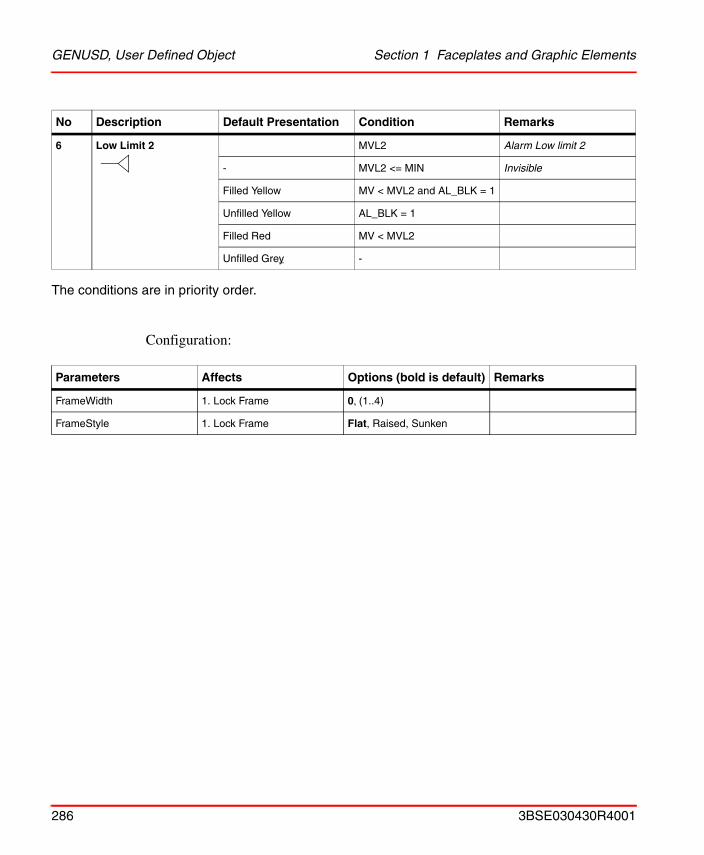
GENUSD, User Defined Object Section 1 Faceplates and Graphic Elements
The conditions are in priority order.
Configuration:
6 Low Limit 2 MVL2 Alarm Low limit 2
- MVL2 <= MIN Invisible
Filled Yellow MV < MVL2 and AL_BLK = 1
Unfilled Yellow AL_BLK = 1
Filled Red MV < MVL2
Unfilled Grey -
Parameters Affects Options (bold is default) Remarks
FrameWidth 1. Lock Frame 0, (1..4)
FrameStyle 1. Lock Frame Flat, Raised, Sunken
No Description Default Presentation Condition Remarks
286 3BSE030430R4001
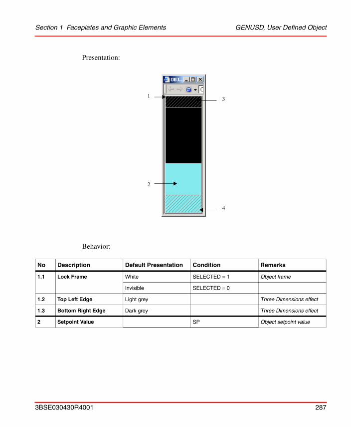
Section 1 Faceplates and Graphic Elements GENUSD, User Defined Object
Presentation:
Behavior:
No Description Default Presentation Condition Remarks
1.1 Lock Frame White SELECTED = 1 Object frame
Invisible SELECTED = 0
1.2 Top Left Edge Light grey Three Dimensions effect
1.3 Bottom Right Edge Dark grey Three Dimensions effect
2 Setpoint Value SP Object setpoint value
1
2
3
4
3BSE030430R4001 287
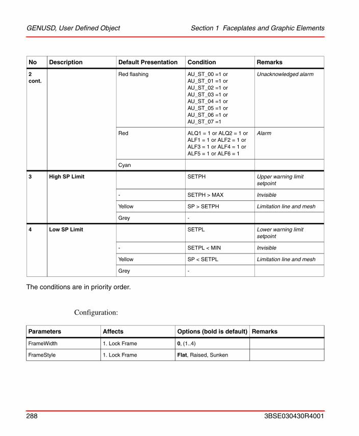
GENUSD, User Defined Object Section 1 Faceplates and Graphic Elements
The conditions are in priority order.
Configuration:
2 cont.
Red flashing AU_ST_00 =1 or AU_ST_01 =1 or AU_ST_02 =1 or AU_ST_03 =1 or AU_ST_04 =1 or AU_ST_05 =1 or AU_ST_06 =1 or AU_ST_07 =1
Unacknowledged alarm
Red ALQ1 = 1 or ALQ2 = 1 orALF1 = 1 or ALF2 = 1 orALF3 = 1 or ALF4 = 1 orALF5 = 1 or ALF6 = 1
Alarm
Cyan
3 High SP Limit SETPH Upper warning limit setpoint
- SETPH > MAX Invisible
Yellow SP > SETPH Limitation line and mesh
Grey -
4 Low SP Limit SETPL Lower warning limit setpoint
- SETPL < MIN Invisible
Yellow SP < SETPL Limitation line and mesh
Grey -
Parameters Affects Options (bold is default) Remarks
FrameWidth 1. Lock Frame 0, (1..4)
FrameStyle 1. Lock Frame Flat, Raised, Sunken
No Description Default Presentation Condition Remarks
288 3BSE030430R4001
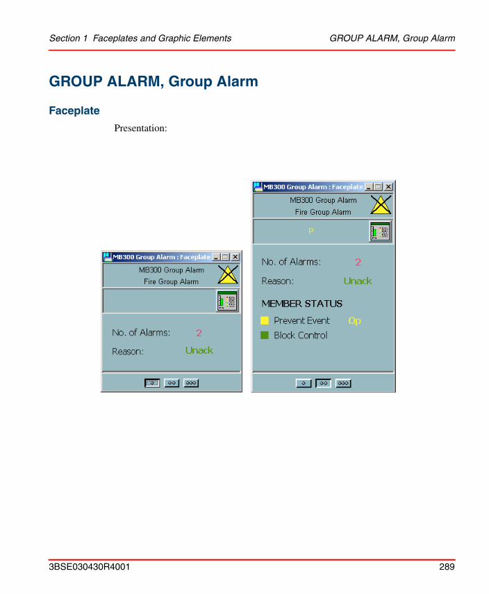
Section 1 Faceplates and Graphic Elements GROUP ALARM, Group Alarm
GROUP ALARM, Group Alarm
Faceplate
Presentation:
3BSE030430R4001 289
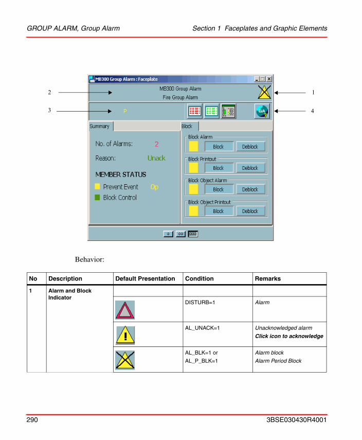
GROUP ALARM, Group Alarm Section 1 Faceplates and Graphic Elements
Behavior:
No Description Default Presentation Condition Remarks
1 Alarm and Block Indicator
DISTURB=1 Alarm
AL_UNACK=1 Unacknowledged alarm
Click icon to acknowledge
AL_BLK=1 or
AL_P_BLK=1
Alarm block
Alarm Period Block
2
3 4
1
290 3BSE030430R4001
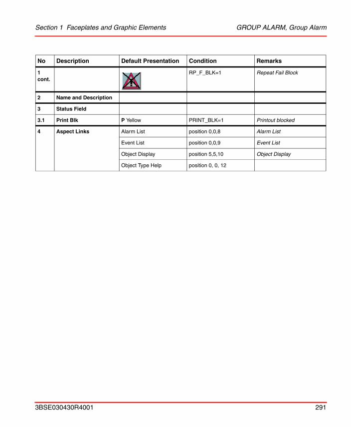
Section 1 Faceplates and Graphic Elements GROUP ALARM, Group Alarm
1 cont.
RP_F_BLK=1 Repeat Fail Block
2 Name and Description
3 Status Field
3.1 Print Blk P Yellow PRINT_BLK=1 Printout blocked
4 Aspect Links Alarm List position 0,0,8 Alarm List
Event List position 0,0,9 Event List
Object Display position 5,5,10 Object Display
Object Type Help position 0, 0, 12
No Description Default Presentation Condition Remarks
3BSE030430R4001 291
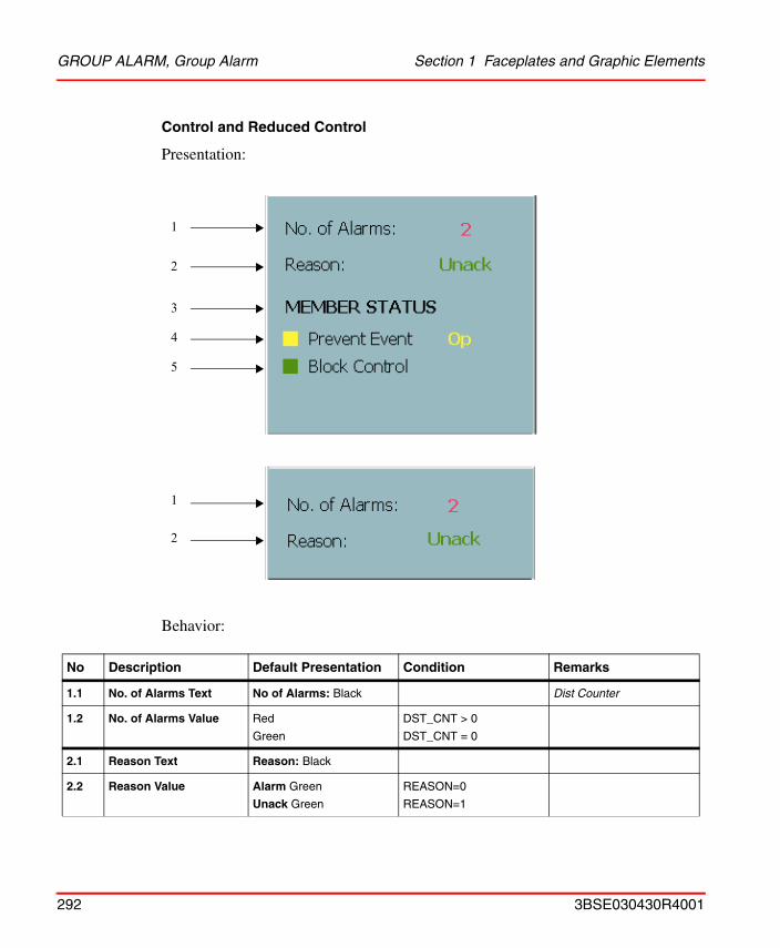
GROUP ALARM, Group Alarm Section 1 Faceplates and Graphic Elements
Control and Reduced Control
Presentation:
Behavior:
No Description Default Presentation Condition Remarks
1.1 No. of Alarms Text No of Alarms: Black Dist Counter
1.2 No. of Alarms Value Red
Green
DST_CNT > 0
DST_CNT = 0
2.1 Reason Text Reason: Black
2.2 Reason Value Alarm Green
Unack Green
REASON=0
REASON=1
1
2
3
4
5
2
1
292 3BSE030430R4001
Section 1 Faceplates and Graphic Elements GROUP ALARM, Group Alarm
Block
Presentation:
3 Member Status MEMBER STATUS black status
4.1 Prevent Event Indication
! Yellow PREV_OP=1 or PREV_PGM=1 or PREV_EXT=1
4.2 Prevent Event Text Prevent Event: Black
4.3 Prevent Event Handling Op Yellow
Pgm Yellow
Ext Yellow
PREV_OP=1 PREV_PGM=1 PREV_EXT=1
5.1 Block Control Indication
! Green BLK_CTRL=1
5.2 Block Control Text Block Control Black
No Description Default Presentation Condition Remarks
1
2
3
4
3BSE030430R4001 293
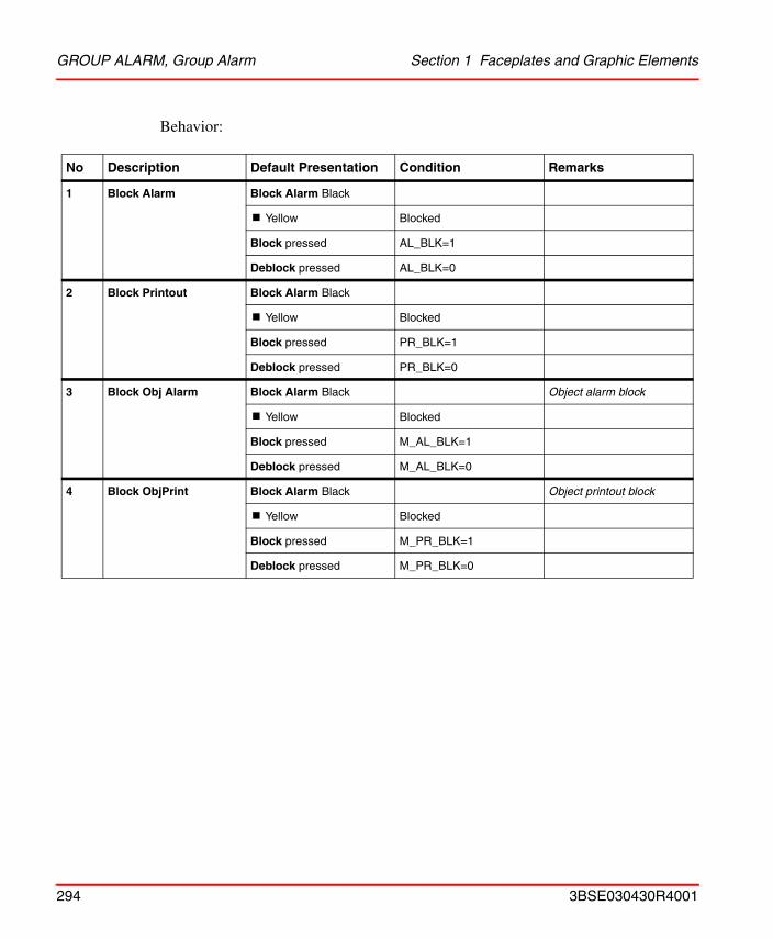
GROUP ALARM, Group Alarm Section 1 Faceplates and Graphic Elements
Behavior:
No Description Default Presentation Condition Remarks
1 Block Alarm Block Alarm Black
! Yellow Blocked
Block pressed AL_BLK=1
Deblock pressed AL_BLK=0
2 Block Printout Block Alarm Black
! Yellow Blocked
Block pressed PR_BLK=1
Deblock pressed PR_BLK=0
3 Block Obj Alarm Block Alarm Black Object alarm block
! Yellow Blocked
Block pressed M_AL_BLK=1
Deblock pressed M_AL_BLK=0
4 Block ObjPrint Block Alarm Black Object printout block
! Yellow Blocked
Block pressed M_PR_BLK=1
Deblock pressed M_PR_BLK=0
294 3BSE030430R4001
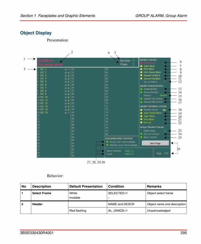
Section 1 Faceplates and Graphic Elements GROUP ALARM, Group Alarm
Object Display
Presentation:
Behavior:
No Description Default Presentation Condition Remarks
1 Select Frame White
Invisible
SELECTED=1
-
Object select frame
2 Header NAME and DESCR Object name and description
Red flashing AL_UNACK=1 Unacknowledged
5
1
2 3
26
27, 28, 29,30
6789
101112
1314151617
1819202122
232425
4
3BSE030430R4001 295
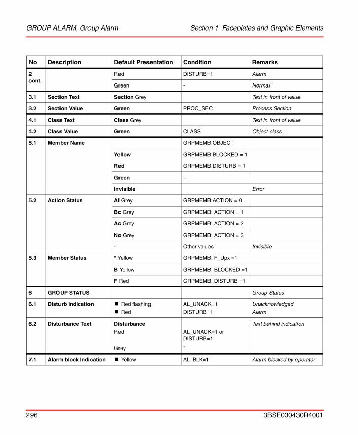
GROUP ALARM, Group Alarm Section 1 Faceplates and Graphic Elements
2 cont.
Red DISTURB=1 Alarm
Green - Normal
3.1 Section Text Section Grey Text in front of value
3.2 Section Value Green PROC_SEC Process Section
4.1 Class Text Class Grey Text in front of value
4.2 Class Value Green CLASS Object class
5.1 Member Name GRPMEMB:OBJECT
Yellow GRPMEMB:BLOCKED = 1
Red GRPMEMB:DISTURB = 1
Green -
Invisible Error
5.2 Action Status Al Grey GRPMEMB:ACTION = 0
Bc Grey GRPMEMB: ACTION = 1
Ac Grey GRPMEMB: ACTION = 2
No Grey GRPMEMB: ACTION = 3
- Other values Invisible
5.3 Member Status * Yellow GRPMEMB: F_Upx =1
B Yellow GRPMEMB: BLOCKED =1
F Red GRPMEMB: DISTURB =1
6 GROUP STATUS Group Status
6.1 Disturb Indication ! Red flashing
! Red
AL_UNACK=1
DISTURB=1
Unacknowledged
Alarm
6.2 Disturbance Text Disturbance
Red
Grey
AL_UNACK=1 or DISTURB=1
-
Text behind indication
7.1 Alarm block Indication ! Yellow AL_BLK=1 Alarm blocked by operator
No Description Default Presentation Condition Remarks
296 3BSE030430R4001
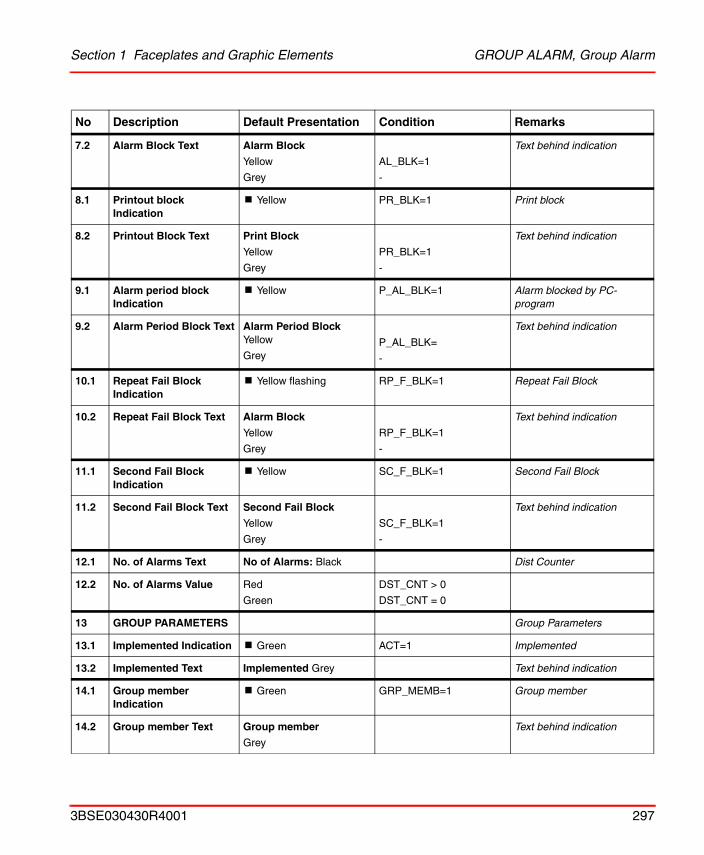
Section 1 Faceplates and Graphic Elements GROUP ALARM, Group Alarm
7.2 Alarm Block Text Alarm Block
Yellow
Grey
AL_BLK=1
-
Text behind indication
8.1 Printout block Indication
! Yellow PR_BLK=1 Print block
8.2 Printout Block Text Print Block
Yellow
Grey
PR_BLK=1
-
Text behind indication
9.1 Alarm period block Indication
! Yellow P_AL_BLK=1 Alarm blocked by PC-program
9.2 Alarm Period Block Text Alarm Period Block Yellow
GreyP_AL_BLK=
-
Text behind indication
10.1 Repeat Fail Block Indication
! Yellow flashing RP_F_BLK=1 Repeat Fail Block
10.2 Repeat Fail Block Text Alarm Block
Yellow
Grey
RP_F_BLK=1
-
Text behind indication
11.1 Second Fail Block Indication
! Yellow SC_F_BLK=1 Second Fail Block
11.2 Second Fail Block Text Second Fail Block
Yellow
Grey
SC_F_BLK=1
-
Text behind indication
12.1 No. of Alarms Text No of Alarms: Black Dist Counter
12.2 No. of Alarms Value Red
Green
DST_CNT > 0
DST_CNT = 0
13 GROUP PARAMETERS Group Parameters
13.1 Implemented Indication ! Green ACT=1 Implemented
13.2 Implemented Text Implemented Grey Text behind indication
14.1 Group member Indication
! Green GRP_MEMB=1 Group member
14.2 Group member Text Group member
Grey
Text behind indication
No Description Default Presentation Condition Remarks
3BSE030430R4001 297
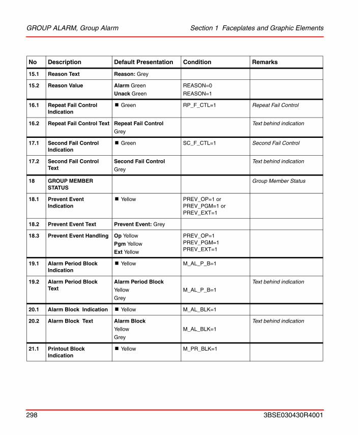
GROUP ALARM, Group Alarm Section 1 Faceplates and Graphic Elements
15.1 Reason Text Reason: Grey
15.2 Reason Value Alarm Green
Unack Green
REASON=0
REASON=1
16.1 Repeat Fail Control Indication
! Green RP_F_CTL=1 Repeat Fail Control
16.2 Repeat Fail Control Text Repeat Fail Control
Grey
Text behind indication
17.1 Second Fail Control Indication
! Green SC_F_CTL=1 Second Fail Control
17.2 Second Fail Control Text
Second Fail Control
Grey
Text behind indication
18 GROUP MEMBER STATUS
Group Member Status
18.1 Prevent Event Indication
! Yellow PREV_OP=1 or PREV_PGM=1 or PREV_EXT=1
18.2 Prevent Event Text Prevent Event: Grey
18.3 Prevent Event Handling Op Yellow
Pgm Yellow
Ext Yellow
PREV_OP=1 PREV_PGM=1 PREV_EXT=1
19.1 Alarm Period Block Indication
! Yellow M_AL_P_B=1
19.2 Alarm Period Block Text
Alarm Period Block
Yellow
Grey
M_AL_P_B=1
Text behind indication
20.1 Alarm Block Indication ! Yellow M_AL_BLK=1
20.2 Alarm Block Text Alarm Block
Yellow
Grey
M_AL_BLK=1
Text behind indication
21.1 Printout Block Indication
! Yellow M_PR_BLK=1
No Description Default Presentation Condition Remarks
298 3BSE030430R4001
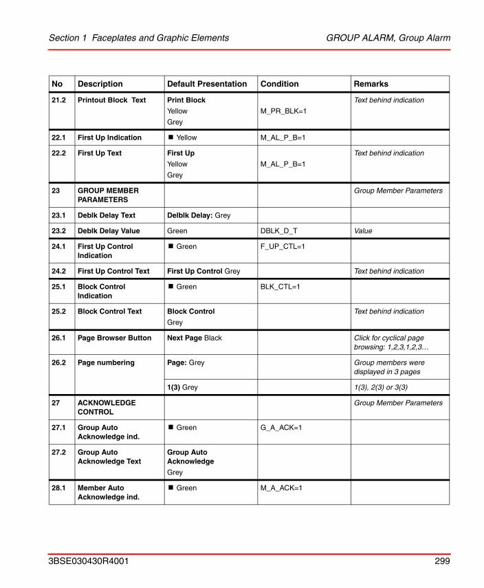
Section 1 Faceplates and Graphic Elements GROUP ALARM, Group Alarm
21.2 Printout Block Text Print Block
Yellow
Grey
M_PR_BLK=1
Text behind indication
22.1 First Up Indication ! Yellow M_AL_P_B=1
22.2 First Up Text First Up
Yellow
Grey
M_AL_P_B=1
Text behind indication
23 GROUP MEMBER PARAMETERS
Group Member Parameters
23.1 Deblk Delay Text Delblk Delay: Grey
23.2 Deblk Delay Value Green DBLK_D_T Value
24.1 First Up Control Indication
! Green F_UP_CTL=1
24.2 First Up Control Text First Up Control Grey Text behind indication
25.1 Block Control Indication
! Green BLK_CTL=1
25.2 Block Control Text Block Control
Grey
Text behind indication
26.1 Page Browser Button Next Page Black Click for cyclical page browsing: 1,2,3,1,2,3…
26.2 Page numbering Page: Grey Group members were displayed in 3 pages
1(3) Grey 1(3), 2(3) or 3(3)
27 ACKNOWLEDGE CONTROL
Group Member Parameters
27.1 Group Auto Acknowledge ind.
! Green G_A_ACK=1
27.2 Group Auto Acknowledge Text
Group Auto Acknowledge
Grey
28.1 Member Auto Acknowledge ind.
! Green M_A_ACK=1
No Description Default Presentation Condition Remarks
3BSE030430R4001 299
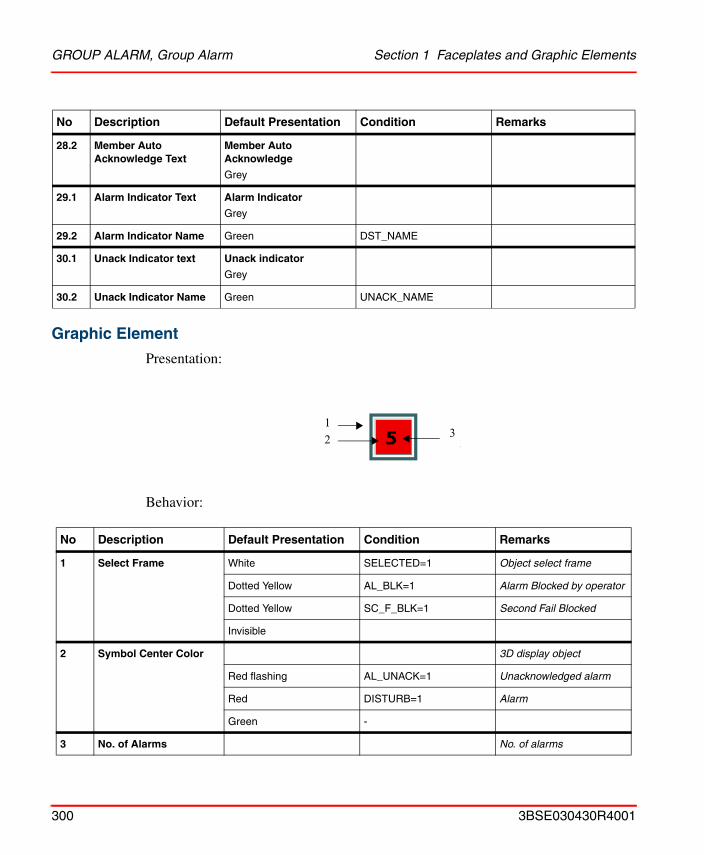
GROUP ALARM, Group Alarm Section 1 Faceplates and Graphic Elements
Graphic Element
Presentation:
Behavior:
28.2 Member Auto Acknowledge Text
Member Auto Acknowledge
Grey
29.1 Alarm Indicator Text Alarm Indicator
Grey
29.2 Alarm Indicator Name Green DST_NAME
30.1 Unack Indicator text Unack indicator
Grey
30.2 Unack Indicator Name Green UNACK_NAME
No Description Default Presentation Condition Remarks
1 Select Frame White SELECTED=1 Object select frame
Dotted Yellow AL_BLK=1 Alarm Blocked by operator
Dotted Yellow SC_F_BLK=1 Second Fail Blocked
Invisible
2 Symbol Center Color 3D display object
Red flashing AL_UNACK=1 Unacknowledged alarm
Red DISTURB=1 Alarm
Green -
3 No. of Alarms No. of alarms
No Description Default Presentation Condition Remarks
33
12
300 3BSE030430R4001
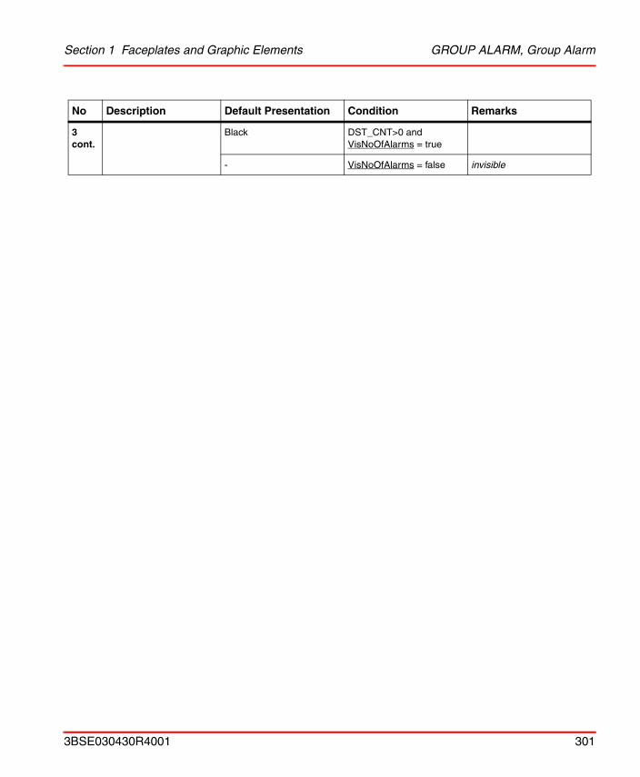
Section 1 Faceplates and Graphic Elements GROUP ALARM, Group Alarm
3 cont.
Black DST_CNT>0 and VisNoOfAlarms = true
- VisNoOfAlarms = false invisible
No Description Default Presentation Condition Remarks
3BSE030430R4001 301
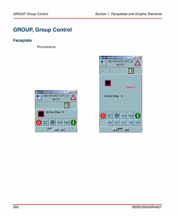
GROUP, Group Control Section 1 Faceplates and Graphic Elements
GROUP, Group Control
Faceplate
Presentation:
302 3BSE030430R4001
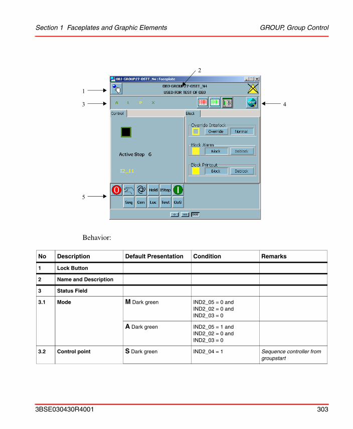
Section 1 Faceplates and Graphic Elements GROUP, Group Control
Behavior:
No Description Default Presentation Condition Remarks
1 Lock Button
2 Name and Description
3 Status Field
3.1 Mode M Dark green IND2_05 = 0 and IND2_02 = 0 and IND2_03 = 0
A Dark green IND2_05 = 1 and IND2_02 = 0 and IND2_03 = 0
3.2 Control point S Dark green IND2_04 = 1 Sequence controller from groupstart
1
3
5
4
2
3BSE030430R4001 303
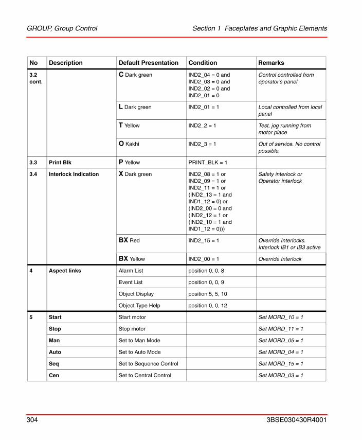
GROUP, Group Control Section 1 Faceplates and Graphic Elements
3.2 cont.
C Dark green IND2_04 = 0 and IND2_03 = 0 and IND2_02 = 0 and IND2_01 = 0
Control controlled from operator’s panel
L Dark green IND2_01 = 1 Local controlled from local panel
T Yellow IND2_2 = 1 Test, jog running from motor place
O Kakhi IND2_3 = 1 Out of service. No control possible.
3.3 Print Blk P Yellow PRINT_BLK = 1
3.4 Interlock Indication X Dark green IND2_08 = 1 orIND2_09 = 1 orIND2_11 = 1 or(IND2_13 = 1 and IND1_12 = 0) or(IND2_00 = 0 and(IND2_12 = 1 or(IND2_10 = 1 and IND1_12 = 0)))
Safety interlock orOperator interlock
BX Red IND2_15 = 1 Override Interlocks. Interlock IB1 or IB3 active
BX Yellow IND2_00 = 1 Override Interlock
4 Aspect links Alarm List position 0, 0, 8
Event List position 0, 0, 9
Object Display position 5, 5, 10
Object Type Help position 0, 0, 12
5 Start Start motor Set MORD_10 = 1
Stop Stop motor Set MORD_11 = 1
Man Set to Man Mode Set MORD_05 = 1
Auto Set to Auto Mode Set MORD_04 = 1
Seq Set to Sequence Control Set MORD_15 = 1
Cen Set to Central Control Set MORD_03 = 1
No Description Default Presentation Condition Remarks
304 3BSE030430R4001
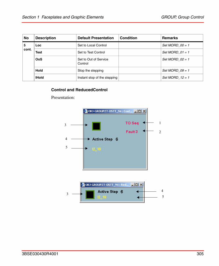
Section 1 Faceplates and Graphic Elements GROUP, Group Control
Control and ReducedControl
Presentation:
5 cont.
Loc Set to Local Control Set MORD_00 = 1
Test Set to Test Control Set MORD_01 = 1
OoS Set to Out of Service Control
Set MORD_02 = 1
Hold Stop the stepping Set MORD_09 = 1
IHold Instant stop of the stepping Set MORD_12 = 1
No Description Default Presentation Condition Remarks
13
5
2
4
354
3BSE030430R4001 305
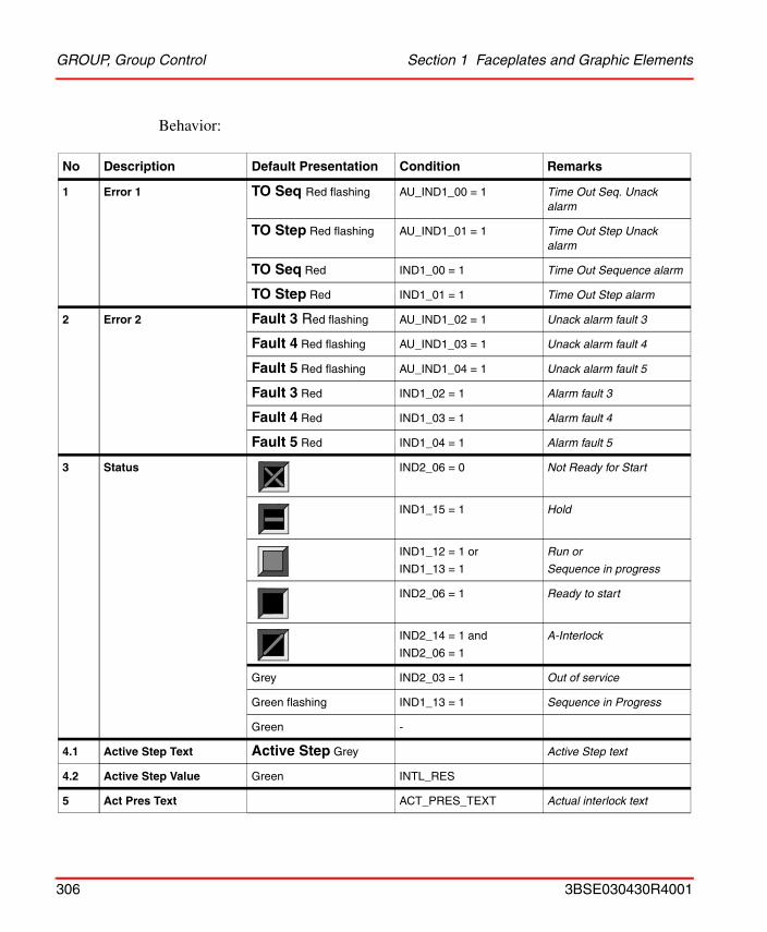
GROUP, Group Control Section 1 Faceplates and Graphic Elements
Behavior:
No Description Default Presentation Condition Remarks
1 Error 1 TO Seq Red flashing AU_IND1_00 = 1 Time Out Seq. Unack alarm
TO Step Red flashing AU_IND1_01 = 1 Time Out Step Unack alarm
TO Seq Red IND1_00 = 1 Time Out Sequence alarm
TO Step Red IND1_01 = 1 Time Out Step alarm
2 Error 2 Fault 3 Red flashing AU_IND1_02 = 1 Unack alarm fault 3
Fault 4 Red flashing AU_IND1_03 = 1 Unack alarm fault 4
Fault 5 Red flashing AU_IND1_04 = 1 Unack alarm fault 5
Fault 3 Red IND1_02 = 1 Alarm fault 3
Fault 4 Red IND1_03 = 1 Alarm fault 4
Fault 5 Red IND1_04 = 1 Alarm fault 5
3 Status IND2_06 = 0 Not Ready for Start
IND1_15 = 1 Hold
IND1_12 = 1 or
IND1_13 = 1
Run or
Sequence in progress
IND2_06 = 1 Ready to start
IND2_14 = 1 and
IND2_06 = 1
A-Interlock
Grey IND2_03 = 1 Out of service
Green flashing IND1_13 = 1 Sequence in Progress
Green -
4.1 Active Step Text Active Step Grey Active Step text
4.2 Active Step Value Green INTL_RES
5 Act Pres Text ACT_PRES_TEXT Actual interlock text
306 3BSE030430R4001
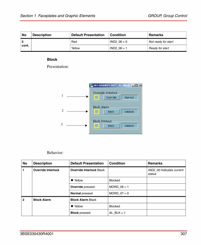
Section 1 Faceplates and Graphic Elements GROUP, Group Control
Block
Presentation:
Behavior:
5 cont.
Red IND2_06 = 0 Not ready for start
Yellow IND2_06 = 1 Ready for start
No Description Default Presentation Condition Remarks
1 Override Interlock Override Interlock Black IND2_00 Indicates current status
! Yellow Blocked
Override pressed MORD_06 = 1
Normal pressed MORD_07 = 0
2 Block Alarm Block Alarm Black
! Yellow Blocked
Block pressed AL_BLK = 1
No Description Default Presentation Condition Remarks
1
2
3
3BSE030430R4001 307
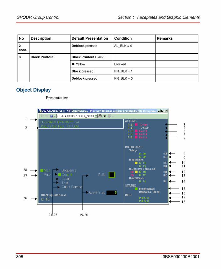
GROUP, Group Control Section 1 Faceplates and Graphic Elements
Object Display
Presentation:
2 cont.
Deblock pressed AL_BLK = 0
3 Block Printout Block Printout Black
! Yellow Blocked
Block pressed PR_BLK = 1
Deblock pressed PR_BLK = 0
No Description Default Presentation Condition Remarks
1
2827
34567
89
1011121314
1516
19-2021-25
26
2
1718
308 3BSE030430R4001
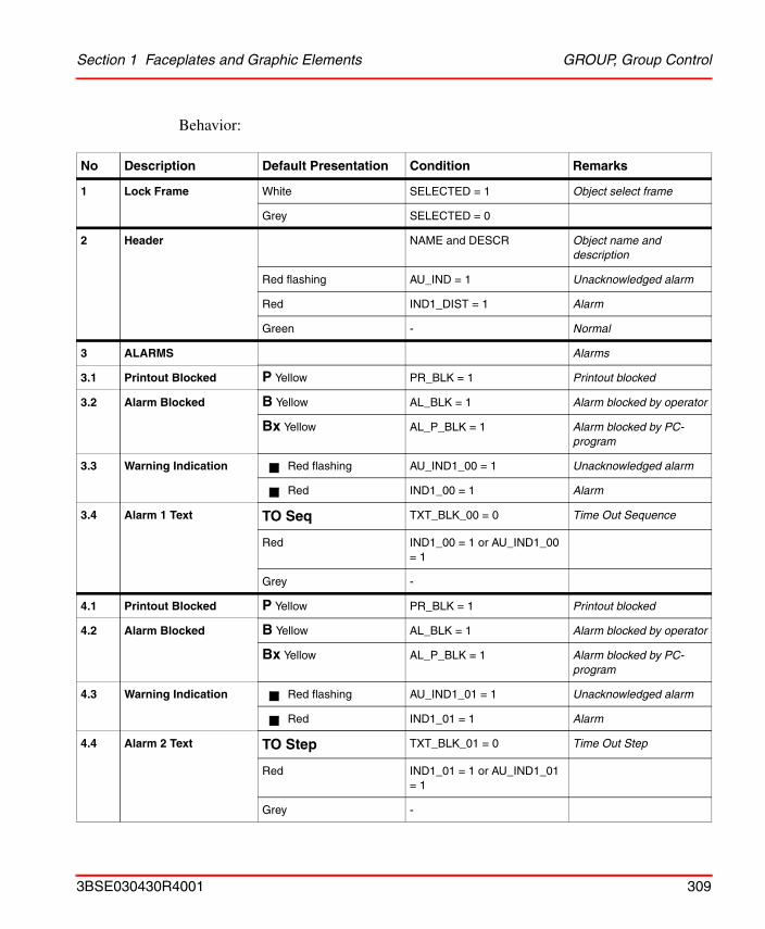
Section 1 Faceplates and Graphic Elements GROUP, Group Control
Behavior:
No Description Default Presentation Condition Remarks
1 Lock Frame White SELECTED = 1 Object select frame
Grey SELECTED = 0
2 Header NAME and DESCR Object name and description
Red flashing AU_IND = 1 Unacknowledged alarm
Red IND1_DIST = 1 Alarm
Green - Normal
3 ALARMS Alarms
3.1 Printout Blocked P Yellow PR_BLK = 1 Printout blocked
3.2 Alarm Blocked B Yellow AL_BLK = 1 Alarm blocked by operator
Bx Yellow AL_P_BLK = 1 Alarm blocked by PC-program
3.3 Warning Indication Red flashing AU_IND1_00 = 1 Unacknowledged alarm
Red IND1_00 = 1 Alarm
3.4 Alarm 1 Text TO Seq TXT_BLK_00 = 0 Time Out Sequence
Red IND1_00 = 1 or AU_IND1_00 = 1
Grey -
4.1 Printout Blocked P Yellow PR_BLK = 1 Printout blocked
4.2 Alarm Blocked B Yellow AL_BLK = 1 Alarm blocked by operator
Bx Yellow AL_P_BLK = 1 Alarm blocked by PC-program
4.3 Warning Indication Red flashing AU_IND1_01 = 1 Unacknowledged alarm
Red IND1_01 = 1 Alarm
4.4 Alarm 2 Text TO Step TXT_BLK_01 = 0 Time Out Step
Red IND1_01 = 1 or AU_IND1_01 = 1
Grey -
3BSE030430R4001 309
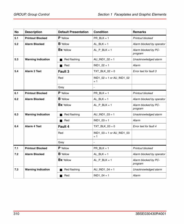
GROUP, Group Control Section 1 Faceplates and Graphic Elements
5.1 Printout Blocked P Yellow PR_BLK = 1 Printout blocked
5.2 Alarm Blocked B Yellow AL_BLK = 1 Alarm blocked by operator
Bx Yellow AL_P_BLK = 1 Alarm blocked by PC-program
5.3 Warning Indication Red flashing AU_IND1_02 = 1 Unacknowledged alarm
Red IND1_02 = 1 Alarm
5.4 Alarm 3 Text Fault 3 TXT_BLK_02 = 0 Error text for fault 3
Red IND1_02 = 1 or AU_IND1_02 = 1
Grey -
6.1 Printout Blocked P Yellow PR_BLK = 1 Printout blocked
6.2 Alarm Blocked B Yellow AL_BLK = 1 Alarm blocked by operator
Bx Yellow AL_P_BLK = 1 Alarm blocked by PC-program
6.3 Warning Indication Red flashing AU_IND1_03 = 1 Unacknowledged alarm
Red IND1_03 = 1 Alarm
6.4 Alarm 4 Text Fault 4 TXT_BLK_03 = 0 Error text for fault 4
Red IND1_03 = 1 or AU_IND1_03 = 1
Grey -
7.1 Printout Blocked P Yellow PR_BLK = 1 Printout blocked
7.2 Alarm Blocked B Yellow AL_BLK = 1 Alarm blocked by operator
Bx Yellow AL_P_BLK = 1 Alarm blocked by PC-program
7.3 Warning Indication Red flashing AU_IND1_04 = 1 Unacknowledged alarm
Red IND1_04 = 1 Alarm
No Description Default Presentation Condition Remarks
310 3BSE030430R4001
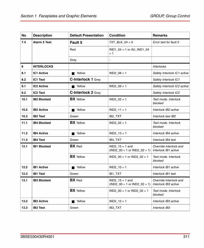
Section 1 Faceplates and Graphic Elements GROUP, Group Control
7.4 Alarm 5 Text Fault 5 TXT_BLK_04 = 0 Error text for fault 5
Red IND1_04 = 1 or AU_IND1_04 = 1
Grey -
8 INTERLOCKS Interlocks
8.1 IC1 Active Yellow IND2_08 = 1 Safety Interlock IC1 active
8.2 IC1 Text C-Interlock 1 Grey Safety Interlock IC1
9.1 IC2 Active Yellow IND2_09 = 1 Safety Interlock IC2 active
9.2 IC2 Text C-Interlock 2 Grey Safety Interlock IC2
10.1 IB2 Blocked BX Yellow IND2_02 = 1 Test mode. Interlock blocked
10.2 IB2 Active Yellow IND2_11 = 1 Interlock IB2 active
10.3 IB2 Text Green IB2_TXT Interlock text IB2
11.1 IB4 Blocked BX Yellow IND2_02 = 1 Test mode. Interlock blocked
11.2 IB4 Active Yellow IND2_13 = 1 Interlock IB4 active
11.3 IB4 Text Green IB4_TXT Interlock IB4 text
12.1 IB1 Blocked BX Red IND2_15 = 1 and(IND2_00 = 1 or IND2_02 = 1)
Override Interlock and Interlock IB1 active
BX Yellow IND2_00 = 1 or IND2_02 = 1 Test mode. Interlock blocked
12.2 IB1 Active Yellow IND2_10 = 1 Interlock IB1 active
12.3 IB1 Text Green IB1_TXT Interlock IB1 text
13.1 IB3 Blocked BX Red IND2_15 = 1 and(IND2_00 = 1 or IND2_02 = 1)
Override Interlock and Interlock IB3 active
BX Yellow IND2_00 = 1 or IND2_02 = 1 Test mode. Interlock blocked
13.2 IB3 Active Yellow IND2_12 = 1 Interlock IB3 active
13.3 IB3 Text Green IB3_TXT Interlock IB3
No Description Default Presentation Condition Remarks
3BSE030430R4001 311
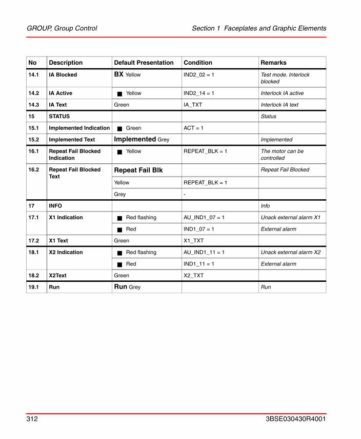
GROUP, Group Control Section 1 Faceplates and Graphic Elements
14.1 IA Blocked BX Yellow IND2_02 = 1 Test mode. Interlock blocked
14.2 IA Active Yellow IND2_14 = 1 Interlock IA active
14.3 IA Text Green IA_TXT Interlock IA text
15 STATUS Status
15.1 Implemented Indication Green ACT = 1
15.2 Implemented Text Implemented Grey Implemented
16.1 Repeat Fail Blocked Indication
Yellow REPEAT_BLK = 1 The motor can be controlled
16.2 Repeat Fail Blocked Text
Repeat Fail Blk Repeat Fail Blocked
Yellow REPEAT_BLK = 1
Grey -
17 INFO Info
17.1 X1 Indication Red flashing AU_IND1_07 = 1 Unack external alarm X1
Red IND1_07 = 1 External alarm
17.2 X1 Text Green X1_TXT
18.1 X2 Indication Red flashing AU_IND1_11 = 1 Unack external alarm X2
Red IND1_11 = 1 External alarm
18.2 X2Text Green X2_TXT
19.1 Run Run Grey Run
No Description Default Presentation Condition Remarks
312 3BSE030430R4001
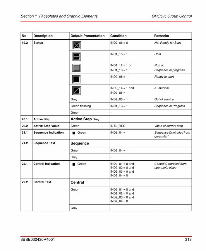
Section 1 Faceplates and Graphic Elements GROUP, Group Control
19.2 Status IND2_06 = 0 Not Ready for Start
IND1_15 = 1 Hold
IND1_12 = 1 or
IND1_13 = 1
Run or
Sequence in progress
IND2_06 = 1 Ready to start
IND2_14 = 1 and
IND2_06 = 1
A-Interlock
Grey IND2_03 = 1 Out of service
Green flashing IND1_13 = 1 Sequence in Progress
Green -
20.1 Active Step Active Step Grey
20.2 Active Step Value Green INTL_RES Value of current step
21.1 Sequence Indication Green IND2_04 = 1 Sequence Controlled from groupstart
21.2 Sequence Text Sequence
Green IND2_04 = 1
Grey -
22.1 Central Indication Green IND2_01 = 0 andIND2_02 = 0 andIND2_03 = 0 andIND2_04 = 0
Central Controlled from operator’s place
22.2 Central Text Central
Green IND2_01 = 0 andIND2_02 = 0 andIND2_03 = 0 andIND2_04 = 0
Grey -
No Description Default Presentation Condition Remarks
3BSE030430R4001 313
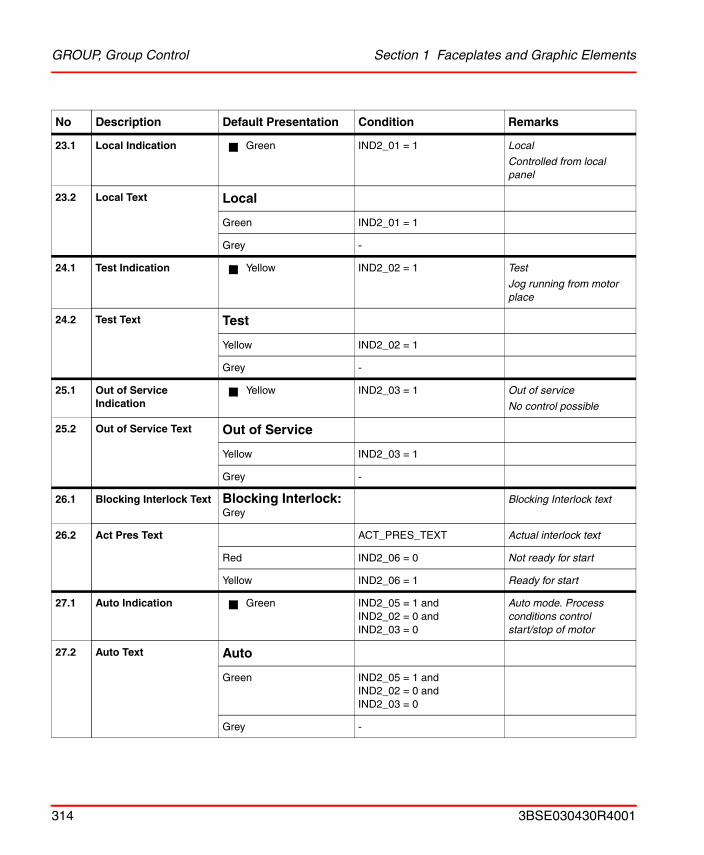
GROUP, Group Control Section 1 Faceplates and Graphic Elements
23.1 Local Indication Green IND2_01 = 1 Local
Controlled from local panel
23.2 Local Text Local
Green IND2_01 = 1
Grey -
24.1 Test Indication Yellow IND2_02 = 1 Test
Jog running from motor place
24.2 Test Text Test
Yellow IND2_02 = 1
Grey -
25.1 Out of Service Indication
Yellow IND2_03 = 1 Out of service
No control possible
25.2 Out of Service Text Out of Service
Yellow IND2_03 = 1
Grey -
26.1 Blocking Interlock Text Blocking Interlock: Grey
Blocking Interlock text
26.2 Act Pres Text ACT_PRES_TEXT Actual interlock text
Red IND2_06 = 0 Not ready for start
Yellow IND2_06 = 1 Ready for start
27.1 Auto Indication Green IND2_05 = 1 andIND2_02 = 0 andIND2_03 = 0
Auto mode. Process conditions control start/stop of motor
27.2 Auto Text Auto
Green IND2_05 = 1 andIND2_02 = 0 andIND2_03 = 0
Grey -
No Description Default Presentation Condition Remarks
314 3BSE030430R4001
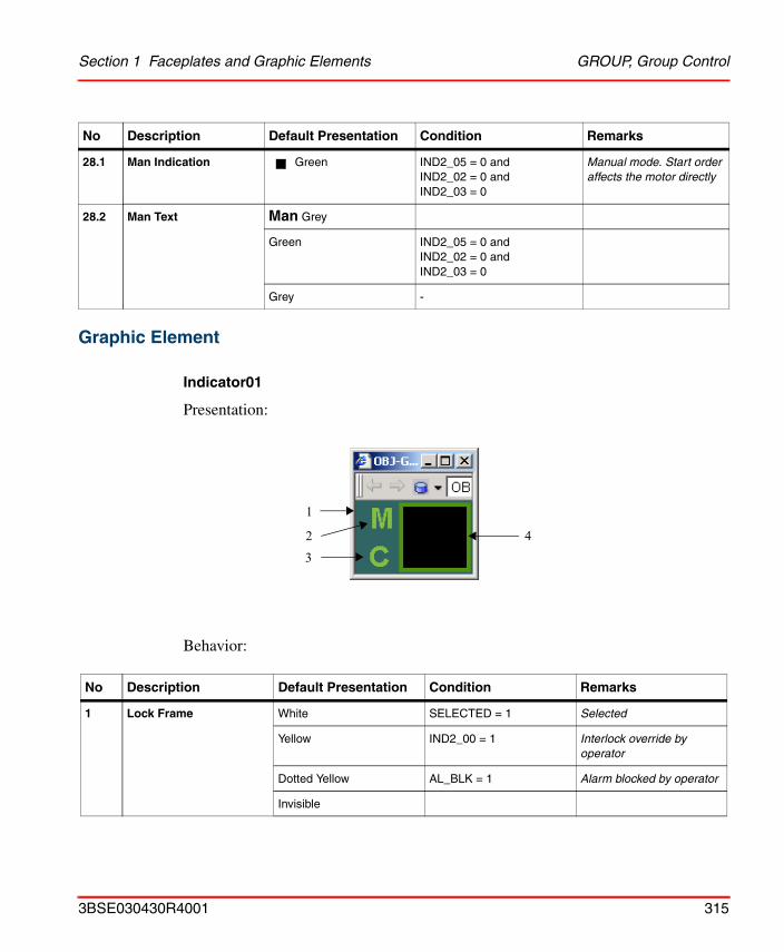
Section 1 Faceplates and Graphic Elements GROUP, Group Control
Graphic Element
Indicator01
Presentation:
Behavior:
28.1 Man Indication Green IND2_05 = 0 andIND2_02 = 0 andIND2_03 = 0
Manual mode. Start order affects the motor directly
28.2 Man Text Man Grey
Green IND2_05 = 0 andIND2_02 = 0 andIND2_03 = 0
Grey -
No Description Default Presentation Condition Remarks
1 Lock Frame White SELECTED = 1 Selected
Yellow IND2_00 = 1 Interlock override by operator
Dotted Yellow AL_BLK = 1 Alarm blocked by operator
Invisible
No Description Default Presentation Condition Remarks
3
1
2 4
3BSE030430R4001 315
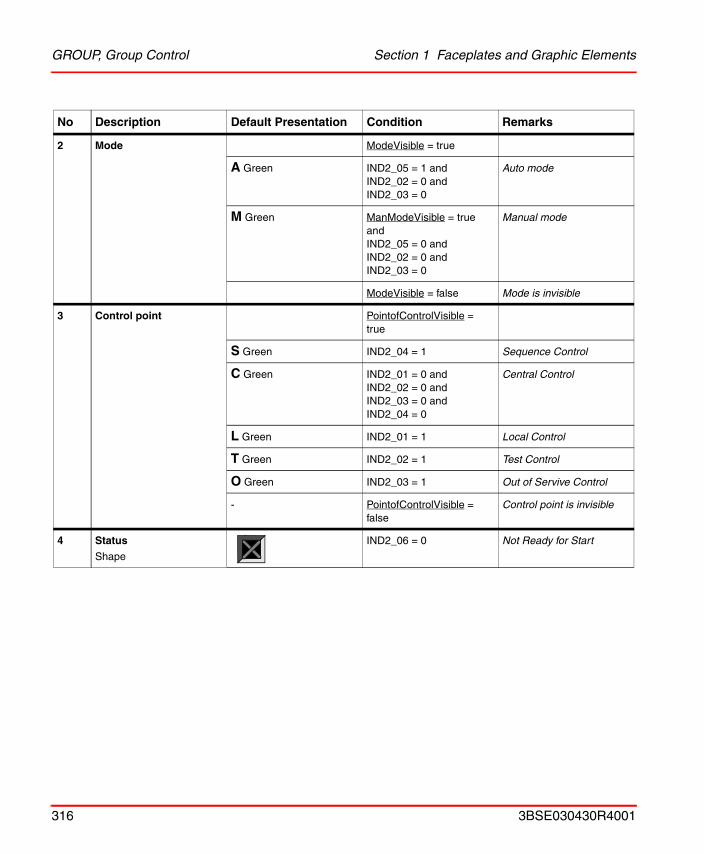
GROUP, Group Control Section 1 Faceplates and Graphic Elements
2 Mode ModeVisible = true
A Green IND2_05 = 1 andIND2_02 = 0 andIND2_03 = 0
Auto mode
M Green ManModeVisible = true andIND2_05 = 0 andIND2_02 = 0 andIND2_03 = 0
Manual mode
ModeVisible = false Mode is invisible
3 Control point PointofControlVisible = true
S Green IND2_04 = 1 Sequence Control
C Green IND2_01 = 0 and IND2_02 = 0 and IND2_03 = 0 and IND2_04 = 0
Central Control
L Green IND2_01 = 1 Local Control
T Green IND2_02 = 1 Test Control
O Green IND2_03 = 1 Out of Servive Control
- PointofControlVisible = false
Control point is invisible
4 Status
Shape
IND2_06 = 0 Not Ready for Start
No Description Default Presentation Condition Remarks
316 3BSE030430R4001
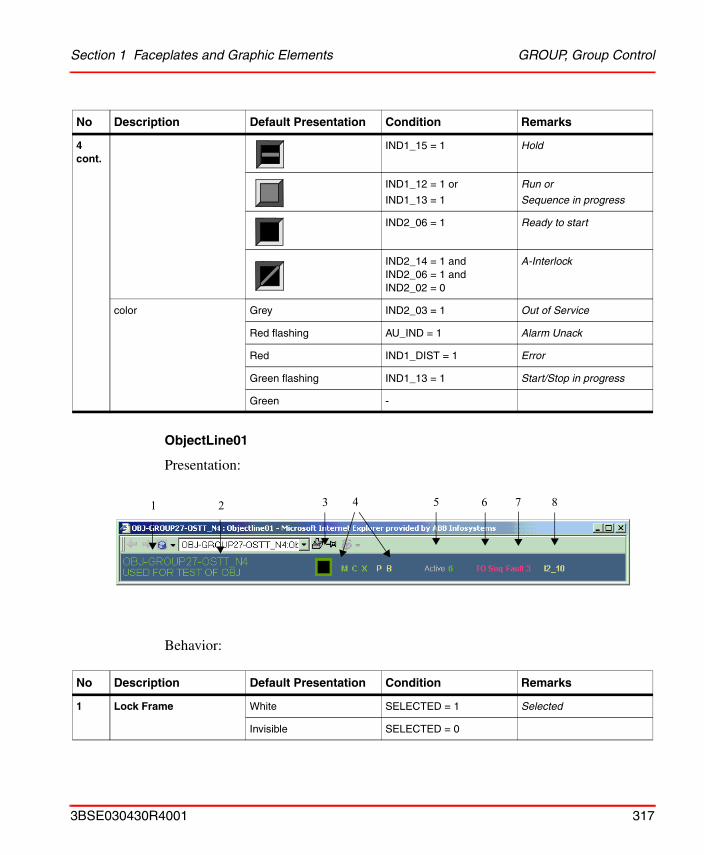
Section 1 Faceplates and Graphic Elements GROUP, Group Control
ObjectLine01
Presentation:
Behavior:
4 cont.
IND1_15 = 1 Hold
IND1_12 = 1 or
IND1_13 = 1
Run or
Sequence in progress
IND2_06 = 1 Ready to start
IND2_14 = 1 andIND2_06 = 1 andIND2_02 = 0
A-Interlock
color Grey IND2_03 = 1 Out of Service
Red flashing AU_IND = 1 Alarm Unack
Red IND1_DIST = 1 Error
Green flashing IND1_13 = 1 Start/Stop in progress
Green -
No Description Default Presentation Condition Remarks
1 Lock Frame White SELECTED = 1 Selected
Invisible SELECTED = 0
No Description Default Presentation Condition Remarks
1 2 3 4 5 6 7 8
3BSE030430R4001 317
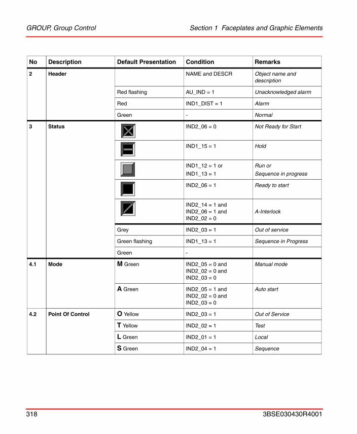
GROUP, Group Control Section 1 Faceplates and Graphic Elements
2 Header NAME and DESCR Object name and description
Red flashing AU_IND = 1 Unacknowledged alarm
Red IND1_DIST = 1 Alarm
Green - Normal
3 Status IND2_06 = 0 Not Ready for Start
IND1_15 = 1 Hold
IND1_12 = 1 or
IND1_13 = 1
Run or
Sequence in progress
IND2_06 = 1 Ready to start
IND2_14 = 1 andIND2_06 = 1 andIND2_02 = 0
A-Interlock
Grey IND2_03 = 1 Out of service
Green flashing IND1_13 = 1 Sequence in Progress
Green -
4.1 Mode M Green IND2_05 = 0 andIND2_02 = 0 andIND2_03 = 0
Manual mode
A Green IND2_05 = 1 andIND2_02 = 0 andIND2_03 = 0
Auto start
4.2 Point Of Control O Yellow IND2_03 = 1 Out of Service
T Yellow IND2_02 = 1 Test
L Green IND2_01 = 1 Local
S Green IND2_04 = 1 Sequence
No Description Default Presentation Condition Remarks
318 3BSE030430R4001
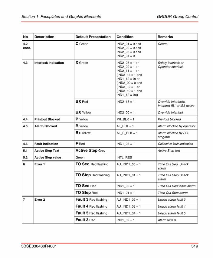
Section 1 Faceplates and Graphic Elements GROUP, Group Control
4.2 cont.
C Green IND2_01 = 0 andIND2_02 = 0 andIND2_03 = 0 andIND2_04 = 0
Central
4.3 Interlock Indication X Green IND2_08 = 1 orIND2_09 = 1 orIND2_11 = 1 or(IND2_13 = 1 and IND1_12 = 0) or(IND2_00 = 0 and(IND2_12 = 1 or(IND2_10 = 1 and IND1_12 = 0)))
Safety interlock orOperator interlock
BX Red IND2_15 = 1 Override Interlocks. Interlock IB1 or IB3 active
BX Yellow IND2_00 = 1 Override Interlock
4.4 Printout Blocked P Yellow PR_BLK = 1 Printout blocked
4.5 Alarm Blocked B Yellow AL_BLK = 1 Alarm blocked by operator
Bx Yellow AL_P_BLK = 1 Alarm blocked by PC-program
4.6 Fault Indication F Red IND1_08 = 1 Collective fault indication
5.1 Active Step Text Active Step Grey Active Step text
5.2 Active Step value Green INTL_RES
6 Error 1 TO Seq Red flashing AU_IND1_00 = 1 Time Out Seq. Unack alarm
TO Step Red flashing AU_IND1_01 = 1 Time Out Step Unack alarm
TO Seq Red IND1_00 = 1 Time Out Sequence alarm
TO Step Red IND1_01 = 1 Time Out Step alarm
7 Error 2 Fault 3 Red flashing AU_IND1_02 = 1 Unack alarm fault 3
Fault 4 Red flashing AU_IND1_03 = 1 Unack alarm fault 4
Fault 5 Red flashing AU_IND1_04 = 1 Unack alarm fault 5
Fault 3 Red IND1_02 = 1 Alarm fault 3
No Description Default Presentation Condition Remarks
3BSE030430R4001 319
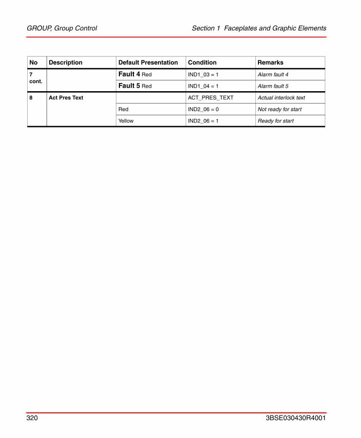
GROUP, Group Control Section 1 Faceplates and Graphic Elements
7 cont.
Fault 4 Red IND1_03 = 1 Alarm fault 4
Fault 5 Red IND1_04 = 1 Alarm fault 5
8 Act Pres Text ACT_PRES_TEXT Actual interlock text
Red IND2_06 = 0 Not ready for start
Yellow IND2_06 = 1 Ready for start
No Description Default Presentation Condition Remarks
320 3BSE030430R4001
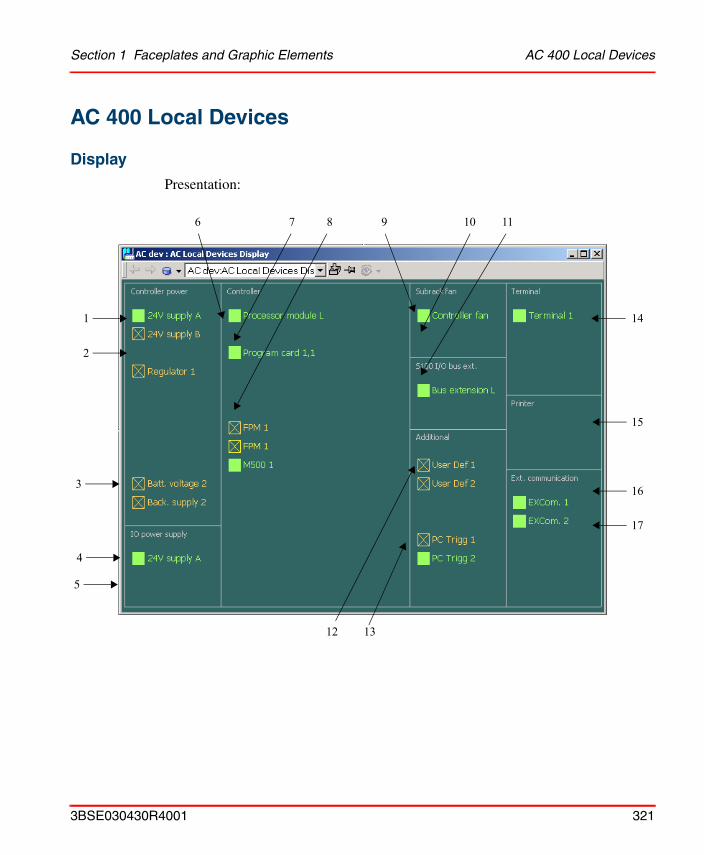
Section 1 Faceplates and Graphic Elements AC 400 Local Devices
AC 400 Local Devices
Display
Presentation:
10
2
1
3
17
16
1312
15
6
14
11
4
5
7 8 9
3BSE030430R4001 321
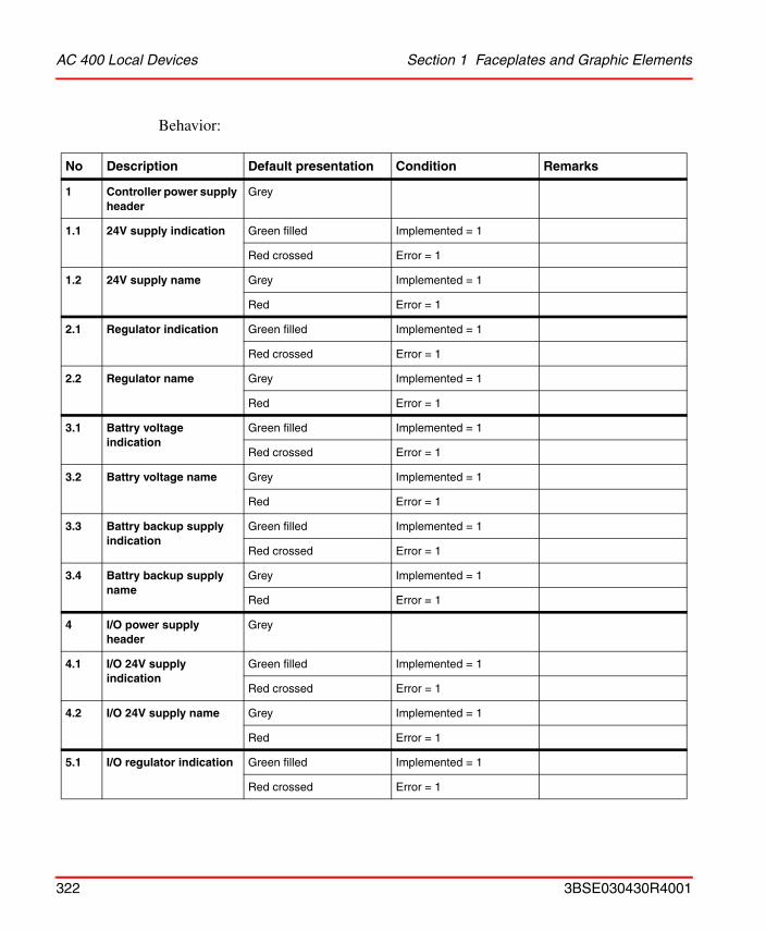
AC 400 Local Devices Section 1 Faceplates and Graphic Elements
Behavior:
No Description Default presentation Condition Remarks
1 Controller power supply header
Grey
1.1 24V supply indication Green filled Implemented = 1
Red crossed Error = 1
1.2 24V supply name Grey Implemented = 1
Red Error = 1
2.1 Regulator indication Green filled Implemented = 1
Red crossed Error = 1
2.2 Regulator name Grey Implemented = 1
Red Error = 1
3.1 Battry voltage indication
Green filled Implemented = 1
Red crossed Error = 1
3.2 Battry voltage name Grey Implemented = 1
Red Error = 1
3.3 Battry backup supply indication
Green filled Implemented = 1
Red crossed Error = 1
3.4 Battry backup supply name
Grey Implemented = 1
Red Error = 1
4 I/O power supply header
Grey
4.1 I/O 24V supply indication
Green filled Implemented = 1
Red crossed Error = 1
4.2 I/O 24V supply name Grey Implemented = 1
Red Error = 1
5.1 I/O regulator indication Green filled Implemented = 1
Red crossed Error = 1
322 3BSE030430R4001
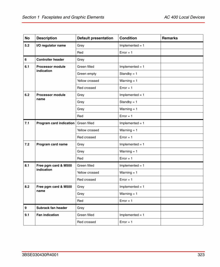
Section 1 Faceplates and Graphic Elements AC 400 Local Devices
5.2 I/O regulator name Grey Implemented = 1
Red Error = 1
6 Controller header Grey
6.1 Processor module indication
Green filled Implemented = 1
Green empty Standby = 1
Yellow crossed Warning = 1
Red crossed Error = 1
6.2 Processor module name
Grey Implemented = 1
Grey Standby = 1
Grey Warning = 1
Red Error = 1
7.1 Program card indication Green filled Implemented = 1
Yellow crossed Warning = 1
Red crossed Error = 1
7.2 Program card name Grey Implemented = 1
Grey Warning = 1
Red Error = 1
8.1 Free pgm card & M500 indication
Green filled Implemented = 1
Yellow crossed Warning = 1
Red crossed Error = 1
8.2 Free pgm card & M500 name
Grey Implemented = 1
Grey Warning = 1
Red Error = 1
9 Subrack fan header Grey
9.1 Fan indication Green filled Implemented = 1
Red crossed Error = 1
No Description Default presentation Condition Remarks
3BSE030430R4001 323
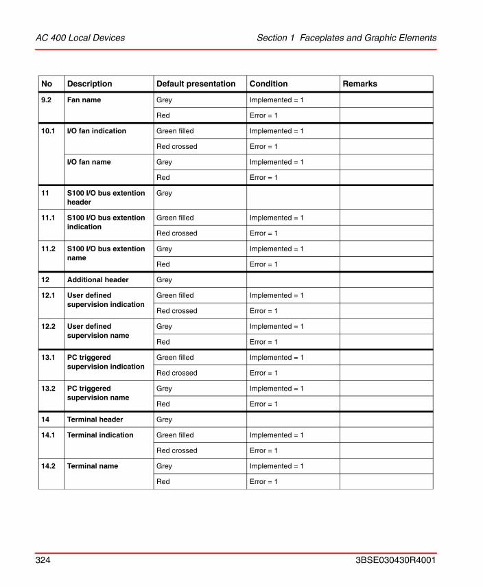
AC 400 Local Devices Section 1 Faceplates and Graphic Elements
9.2 Fan name Grey Implemented = 1
Red Error = 1
10.1 I/O fan indication Green filled Implemented = 1
Red crossed Error = 1
I/O fan name Grey Implemented = 1
Red Error = 1
11 S100 I/O bus extention header
Grey
11.1 S100 I/O bus extention indication
Green filled Implemented = 1
Red crossed Error = 1
11.2 S100 I/O bus extention name
Grey Implemented = 1
Red Error = 1
12 Additional header Grey
12.1 User defined supervision indication
Green filled Implemented = 1
Red crossed Error = 1
12.2 User defined supervision name
Grey Implemented = 1
Red Error = 1
13.1 PC triggered supervision indication
Green filled Implemented = 1
Red crossed Error = 1
13.2 PC triggered supervision name
Grey Implemented = 1
Red Error = 1
14 Terminal header Grey
14.1 Terminal indication Green filled Implemented = 1
Red crossed Error = 1
14.2 Terminal name Grey Implemented = 1
Red Error = 1
No Description Default presentation Condition Remarks
324 3BSE030430R4001
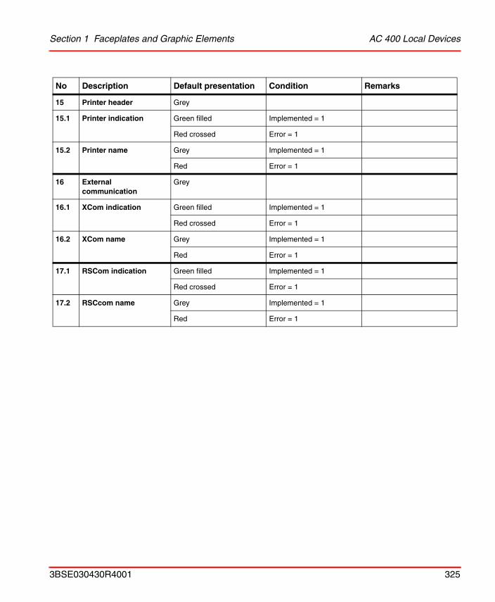
Section 1 Faceplates and Graphic Elements AC 400 Local Devices
15 Printer header Grey
15.1 Printer indication Green filled Implemented = 1
Red crossed Error = 1
15.2 Printer name Grey Implemented = 1
Red Error = 1
16 External communication
Grey
16.1 XCom indication Green filled Implemented = 1
Red crossed Error = 1
16.2 XCom name Grey Implemented = 1
Red Error = 1
17.1 RSCom indication Green filled Implemented = 1
Red crossed Error = 1
17.2 RSCcom name Grey Implemented = 1
Red Error = 1
No Description Default presentation Condition Remarks
3BSE030430R4001 325
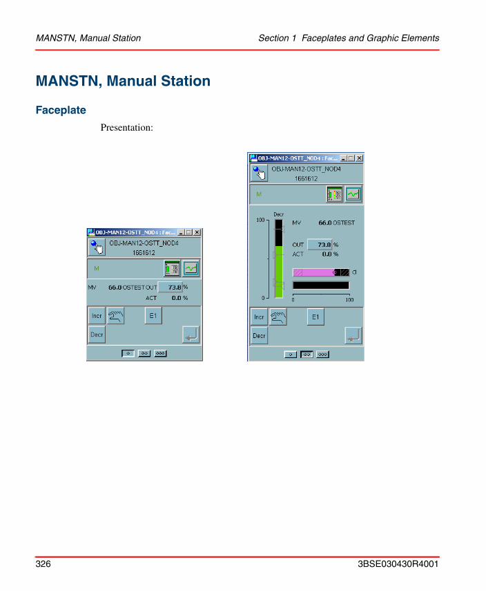
MANSTN, Manual Station Section 1 Faceplates and Graphic Elements
MANSTN, Manual Station
Faceplate
Presentation:
326 3BSE030430R4001
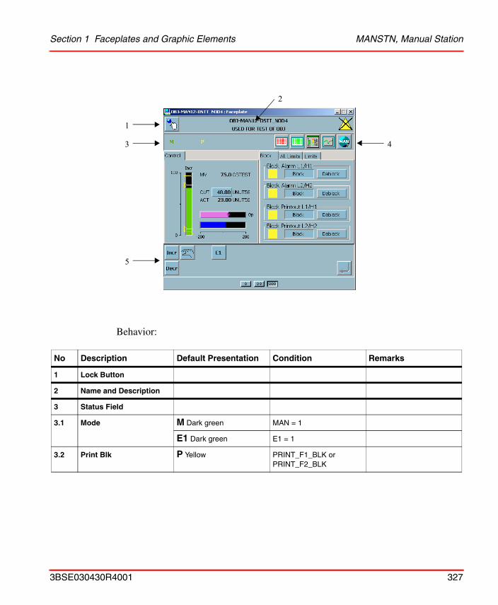
Section 1 Faceplates and Graphic Elements MANSTN, Manual Station
Behavior:
No Description Default Presentation Condition Remarks
1 Lock Button
2 Name and Description
3 Status Field
3.1 Mode M Dark green MAN = 1
E1 Dark green E1 = 1
3.2 Print Blk P Yellow PRINT_F1_BLK orPRINT_F2_BLK
1
3
5
4
2
3BSE030430R4001 327
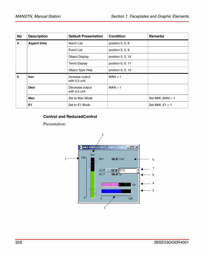
MANSTN, Manual Station Section 1 Faceplates and Graphic Elements
Control and ReducedControl
Presentation:
4 Aspect links Alarm List position 0, 0, 8
Event List position 0, 0, 9
Object Display position 5, 5, 10
Trend Display position 6, 6, 11
Object Type Help position 0, 0, 12
5 Incr Increase output with 0,5 unit
MAN = 1
Decr Decrease output with 0,5 unit
MAN = 1
Man Set to Man Mode Set MMI_MAN = 1
E1 Set to E1 Mode Set MMI_E1 = 1
No Description Default Presentation Condition Remarks
7
8
61
5
2
4
3
328 3BSE030430R4001
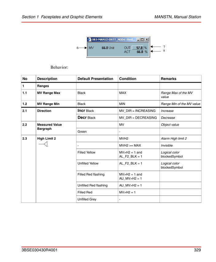
Section 1 Faceplates and Graphic Elements MANSTN, Manual Station
Behavior:
No Description Default Presentation Condition Remarks
1 Ranges
1.1 MV Range Max Black MAX Range Max of the MV value
1.2 MV Range Min Black MIN Range Min of the MV value
2.1 Direction Incr Black MV_DIR = INCREASING Increase
Decr Black MV_DIR = DECREASING Decrease
2.2 Measured Value Bargraph
MV Object value
Green -
2.3 High Limit 2 MVH2 Alarm High limit 2
- MVH2 >= MAX Invisible
Filled Yellow MV>H2 = 1 and AL_F2_BLK = 1
Logical colorblockedSymbol
Unfilled Yellow AL_F2_BLK = 1 Logical colorblockedSymbol
Filled Red flashing MV>H2 = 1 and AU_MV>H2 = 1
Unfilled Red flashing AU_MV>H2 = 1
Filled Red MV>H2 = 1
Unfilled Grey -
78
6
3BSE030430R4001 329
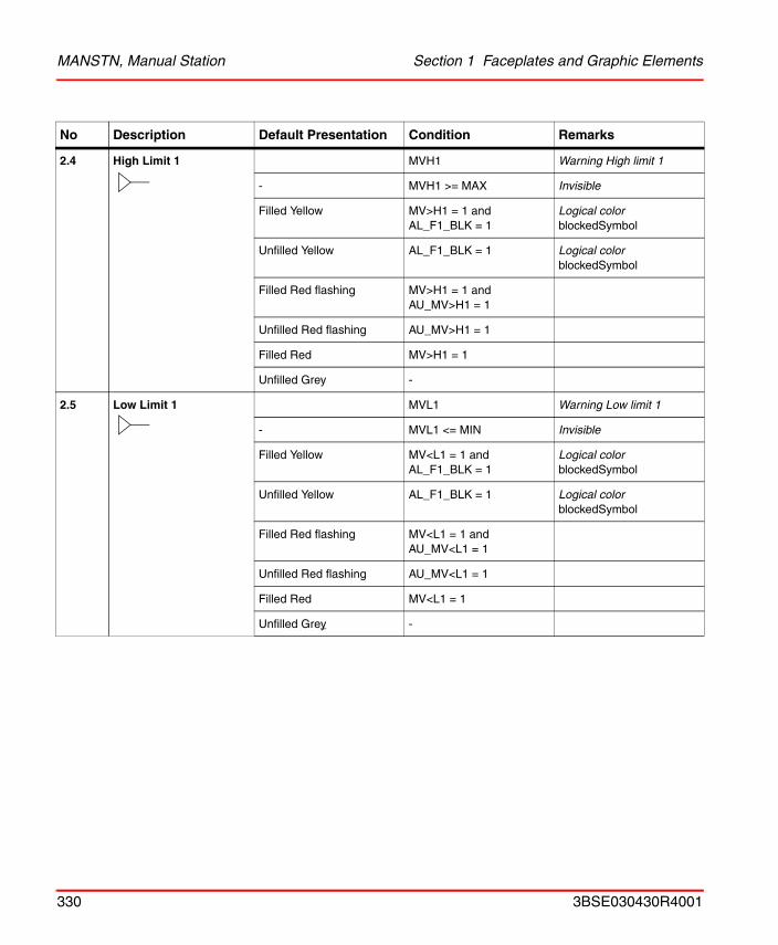
MANSTN, Manual Station Section 1 Faceplates and Graphic Elements
2.4 High Limit 1 MVH1 Warning High limit 1
- MVH1 >= MAX Invisible
Filled Yellow MV>H1 = 1 and AL_F1_BLK = 1
Logical colorblockedSymbol
Unfilled Yellow AL_F1_BLK = 1 Logical colorblockedSymbol
Filled Red flashing MV>H1 = 1 and AU_MV>H1 = 1
Unfilled Red flashing AU_MV>H1 = 1
Filled Red MV>H1 = 1
Unfilled Grey -
2.5 Low Limit 1 MVL1 Warning Low limit 1
- MVL1 <= MIN Invisible
Filled Yellow MV<L1 = 1 and AL_F1_BLK = 1
Logical colorblockedSymbol
Unfilled Yellow AL_F1_BLK = 1 Logical colorblockedSymbol
Filled Red flashing MV<L1 = 1 and AU_MV<L1 = 1
Unfilled Red flashing AU_MV<L1 = 1
Filled Red MV<L1 = 1
Unfilled Grey -
No Description Default Presentation Condition Remarks
330 3BSE030430R4001
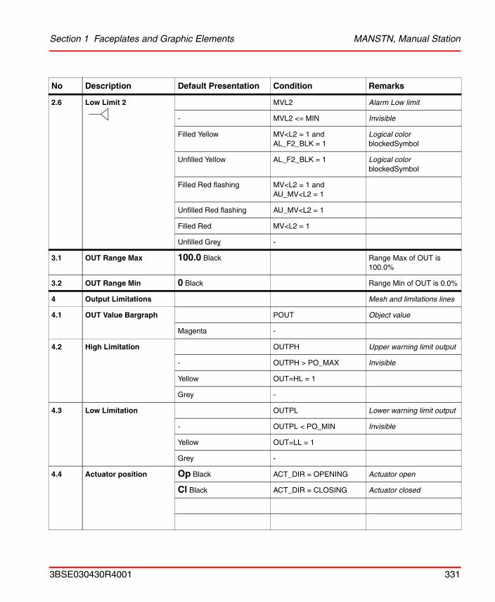
Section 1 Faceplates and Graphic Elements MANSTN, Manual Station
2.6 Low Limit 2 MVL2 Alarm Low limit
- MVL2 <= MIN Invisible
Filled Yellow MV<L2 = 1 and AL_F2_BLK = 1
Logical colorblockedSymbol
Unfilled Yellow AL_F2_BLK = 1 Logical colorblockedSymbol
Filled Red flashing MV<L2 = 1 and AU_MV<L2 = 1
Unfilled Red flashing AU_MV<L2 = 1
Filled Red MV<L2 = 1
Unfilled Grey -
3.1 OUT Range Max 100.0 Black Range Max of OUT is 100.0%
3.2 OUT Range Min 0 Black Range Min of OUT is 0.0%
4 Output Limitations Mesh and limitations lines
4.1 OUT Value Bargraph POUT Object value
Magenta -
4.2 High Limitation OUTPH Upper warning limit output
- OUTPH > PO_MAX Invisible
Yellow OUT=HL = 1
Grey -
4.3 Low Limitation OUTPL Lower warning limit output
- OUTPL < PO_MIN Invisible
Yellow OUT=LL = 1
Grey -
4.4 Actuator position Op Black ACT_DIR = OPENING Actuator open
Cl Black ACT_DIR = CLOSING Actuator closed
No Description Default Presentation Condition Remarks
3BSE030430R4001 331
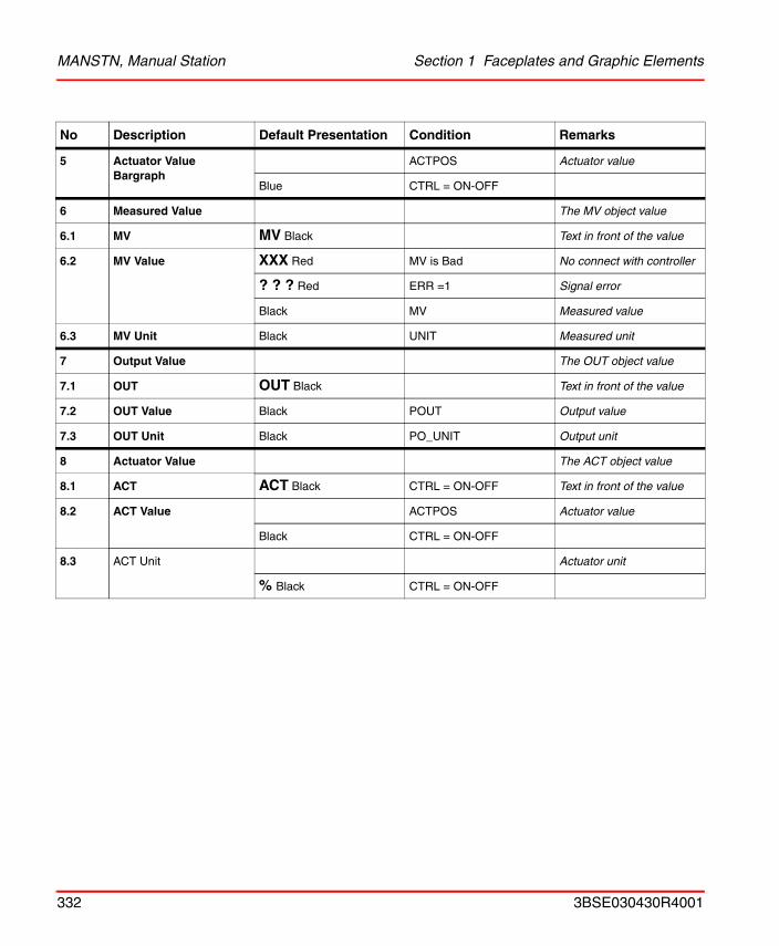
MANSTN, Manual Station Section 1 Faceplates and Graphic Elements
5 Actuator Value Bargraph
ACTPOS Actuator value
Blue CTRL = ON-OFF
6 Measured Value The MV object value
6.1 MV MV Black Text in front of the value
6.2 MV Value XXX Red MV is Bad No connect with controller
? ? ? Red ERR =1 Signal error
Black MV Measured value
6.3 MV Unit Black UNIT Measured unit
7 Output Value The OUT object value
7.1 OUT OUT Black Text in front of the value
7.2 OUT Value Black POUT Output value
7.3 OUT Unit Black PO_UNIT Output unit
8 Actuator Value The ACT object value
8.1 ACT ACT Black CTRL = ON-OFF Text in front of the value
8.2 ACT Value ACTPOS Actuator value
Black CTRL = ON-OFF
8.3 ACT Unit Actuator unit
% Black CTRL = ON-OFF
No Description Default Presentation Condition Remarks
332 3BSE030430R4001
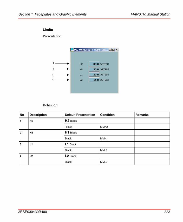
Section 1 Faceplates and Graphic Elements MANSTN, Manual Station
Limits
Presentation:
Behavior:
No Description Default Presentation Condition Remarks
1 H2 H2 Black
Black MVH2
2 H1 H1 Black
Black MVH1
3 L1 L1 Black
Black MVL1
4 L2 L2 Black
Black MVL2
1
2
34
3BSE030430R4001 333
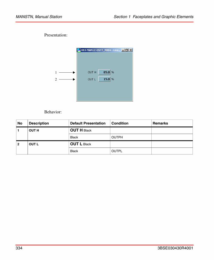
MANSTN, Manual Station Section 1 Faceplates and Graphic Elements
Presentation:
Behavior:
No Description Default Presentation Condition Remarks
1 OUT H OUT H Black
Black OUTPH
2 OUT L OUT L Black
Black OUTPL
1
2
334 3BSE030430R4001
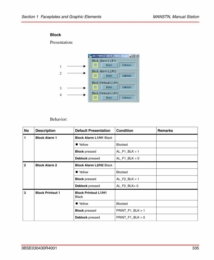
Section 1 Faceplates and Graphic Elements MANSTN, Manual Station
Block
Presentation:
Behavior:
No Description Default Presentation Condition Remarks
1 Block Alarm 1 Block Alarm L1/H1 Black
! Yellow Blocked
Block pressed AL_F1_BLK = 1
Deblock pressed AL_F1_BLK = 0
2 Block Alarm 2 Block Alarm L2/H2 Black
! Yellow Blocked
Block pressed AL_F2_BLK = 1
Deblock pressed AL_F2_BLK= 0
3 Block Printout 1 Block Printout L1/H1 Black
! Yellow Blocked
Block pressed PRINT_F1_BLK = 1
Deblock pressed PRINT_F1_BLK = 0
1
2
3
4
3BSE030430R4001 335
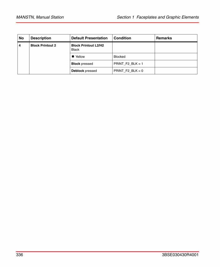
MANSTN, Manual Station Section 1 Faceplates and Graphic Elements
4 Block Printout 2 Block Printout L2/H2 Black
! Yellow Blocked
Block pressed PRINT_F2_BLK = 1
Deblock pressed PRINT_F2_BLK = 0
No Description Default Presentation Condition Remarks
336 3BSE030430R4001
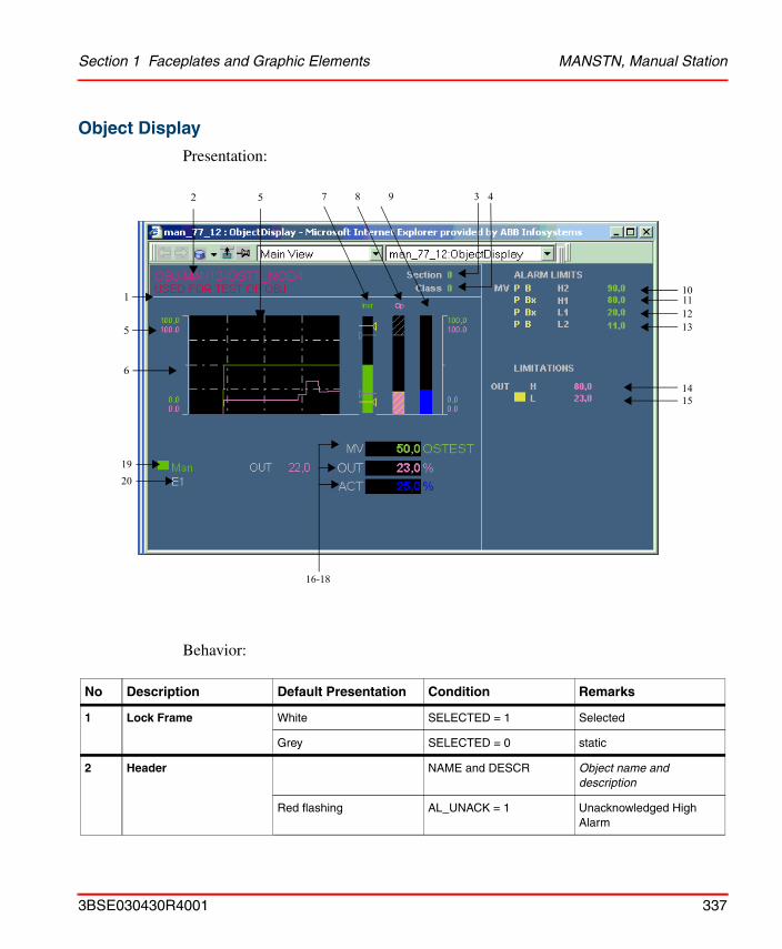
Section 1 Faceplates and Graphic Elements MANSTN, Manual Station
Object Display
Presentation:
Behavior:
No Description Default Presentation Condition Remarks
1 Lock Frame White SELECTED = 1 Selected
Grey SELECTED = 0 static
2 Header NAME and DESCR Object name and description
Red flashing AL_UNACK = 1 Unacknowledged High Alarm
5
10
3 42
1
5
6
1920
16-18
111213
1415
7 8 9
3BSE030430R4001 337
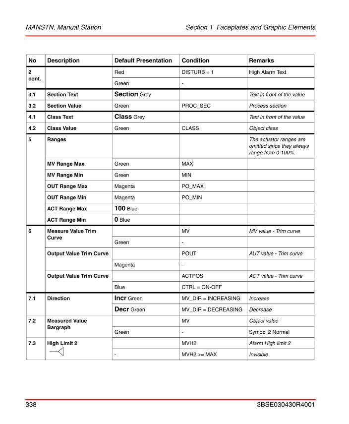
MANSTN, Manual Station Section 1 Faceplates and Graphic Elements
2 cont.
Red DISTURB = 1 High Alarm Text
Green -
3.1 Section Text Section Grey Text in front of the value
3.2 Section Value Green PROC_SEC Process section
4.1 Class Text Class Grey Text in front of the value
4.2 Class Value Green CLASS Object class
5 Ranges The actuator ranges are omitted since they always range from 0-100%.
MV Range Max Green MAX
MV Range Min Green MIN
OUT Range Max Magenta PO_MAX
OUT Range Min Magenta PO_MIN
ACT Range Max 100 Blue
ACT Range Min 0 Blue
6 Measure Value Trim Curve
MV MV value - Trim curve
Green -
Output Value Trim Curve POUT AUT value - Trim curve
Magenta -
Output Value Trim Curve ACTPOS ACT value - Trim curve
Blue CTRL = ON-OFF
7.1 Direction Incr Green MV_DIR = INCREASING Increase
Decr Green MV_DIR = DECREASING Decrease
7.2 Measured Value Bargraph
MV Object value
Green - Symbol 2 Normal
7.3 High Limit 2 MVH2 Alarm High limit 2
- MVH2 >= MAX Invisible
No Description Default Presentation Condition Remarks
338 3BSE030430R4001
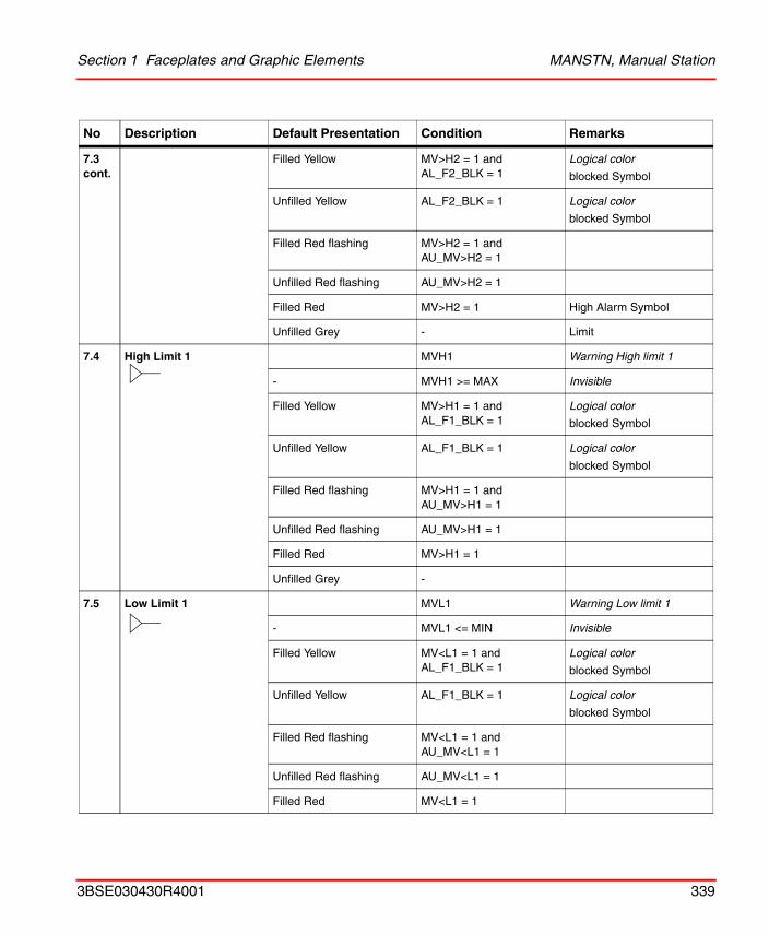
Section 1 Faceplates and Graphic Elements MANSTN, Manual Station
7.3 cont.
Filled Yellow MV>H2 = 1 and AL_F2_BLK = 1
Logical color
blocked Symbol
Unfilled Yellow AL_F2_BLK = 1 Logical color
blocked Symbol
Filled Red flashing MV>H2 = 1 and AU_MV>H2 = 1
Unfilled Red flashing AU_MV>H2 = 1
Filled Red MV>H2 = 1 High Alarm Symbol
Unfilled Grey - Limit
7.4 High Limit 1 MVH1 Warning High limit 1
- MVH1 >= MAX Invisible
Filled Yellow MV>H1 = 1 and AL_F1_BLK = 1
Logical color
blocked Symbol
Unfilled Yellow AL_F1_BLK = 1 Logical color
blocked Symbol
Filled Red flashing MV>H1 = 1 and AU_MV>H1 = 1
Unfilled Red flashing AU_MV>H1 = 1
Filled Red MV>H1 = 1
Unfilled Grey -
7.5 Low Limit 1 MVL1 Warning Low limit 1
- MVL1 <= MIN Invisible
Filled Yellow MV<L1 = 1 and AL_F1_BLK = 1
Logical color
blocked Symbol
Unfilled Yellow AL_F1_BLK = 1 Logical color
blocked Symbol
Filled Red flashing MV<L1 = 1 and AU_MV<L1 = 1
Unfilled Red flashing AU_MV<L1 = 1
Filled Red MV<L1 = 1
No Description Default Presentation Condition Remarks
3BSE030430R4001 339
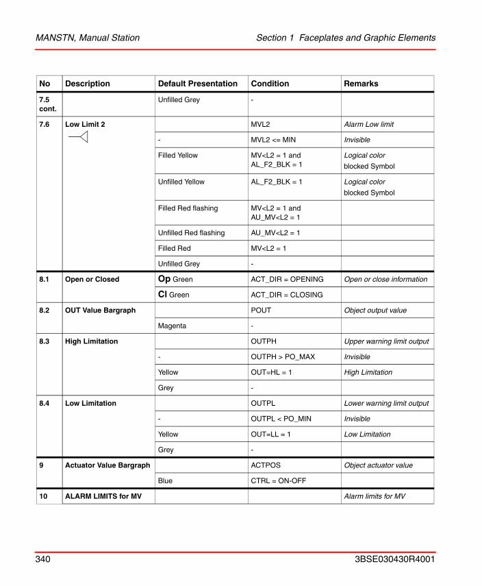
MANSTN, Manual Station Section 1 Faceplates and Graphic Elements
7.5 cont.
Unfilled Grey -
7.6 Low Limit 2 MVL2 Alarm Low limit
- MVL2 <= MIN Invisible
Filled Yellow MV<L2 = 1 and AL_F2_BLK = 1
Logical color
blocked Symbol
Unfilled Yellow AL_F2_BLK = 1 Logical color
blocked Symbol
Filled Red flashing MV<L2 = 1 and AU_MV<L2 = 1
Unfilled Red flashing AU_MV<L2 = 1
Filled Red MV<L2 = 1
Unfilled Grey -
8.1 Open or Closed Op Green ACT_DIR = OPENING Open or close information
Cl Green ACT_DIR = CLOSING
8.2 OUT Value Bargraph POUT Object output value
Magenta -
8.3 High Limitation OUTPH Upper warning limit output
- OUTPH > PO_MAX Invisible
Yellow OUT=HL = 1 High Limitation
Grey -
8.4 Low Limitation OUTPL Lower warning limit output
- OUTPL < PO_MIN Invisible
Yellow OUT=LL = 1 Low Limitation
Grey -
9 Actuator Value Bargraph ACTPOS Object actuator value
Blue CTRL = ON-OFF
10 ALARM LIMITS for MV Alarm limits for MV
No Description Default Presentation Condition Remarks
340 3BSE030430R4001
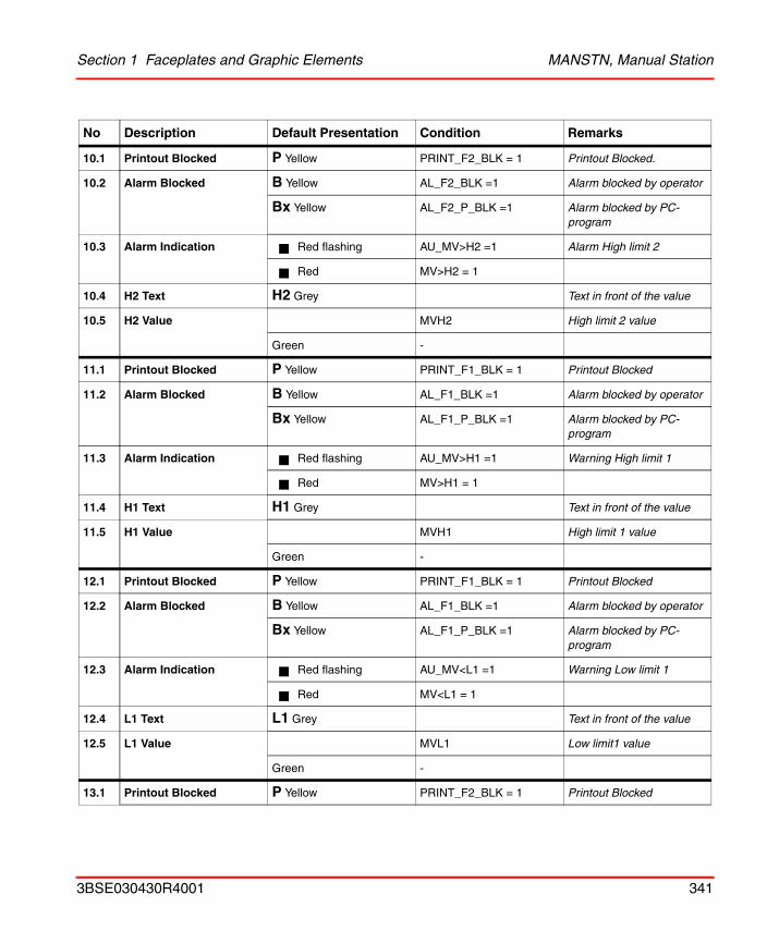
Section 1 Faceplates and Graphic Elements MANSTN, Manual Station
10.1 Printout Blocked P Yellow PRINT_F2_BLK = 1 Printout Blocked.
10.2 Alarm Blocked B Yellow AL_F2_BLK =1 Alarm blocked by operator
Bx Yellow AL_F2_P_BLK =1 Alarm blocked by PC-program
10.3 Alarm Indication Red flashing AU_MV>H2 =1 Alarm High limit 2
Red MV>H2 = 1
10.4 H2 Text H2 Grey Text in front of the value
10.5 H2 Value MVH2 High limit 2 value
Green -
11.1 Printout Blocked P Yellow PRINT_F1_BLK = 1 Printout Blocked
11.2 Alarm Blocked B Yellow AL_F1_BLK =1 Alarm blocked by operator
Bx Yellow AL_F1_P_BLK =1 Alarm blocked by PC-program
11.3 Alarm Indication Red flashing AU_MV>H1 =1 Warning High limit 1
Red MV>H1 = 1
11.4 H1 Text H1 Grey Text in front of the value
11.5 H1 Value MVH1 High limit 1 value
Green -
12.1 Printout Blocked P Yellow PRINT_F1_BLK = 1 Printout Blocked
12.2 Alarm Blocked B Yellow AL_F1_BLK =1 Alarm blocked by operator
Bx Yellow AL_F1_P_BLK =1 Alarm blocked by PC-program
12.3 Alarm Indication Red flashing AU_MV<L1 =1 Warning Low limit 1
Red MV<L1 = 1
12.4 L1 Text L1 Grey Text in front of the value
12.5 L1 Value MVL1 Low limit1 value
Green -
13.1 Printout Blocked P Yellow PRINT_F2_BLK = 1 Printout Blocked
No Description Default Presentation Condition Remarks
3BSE030430R4001 341
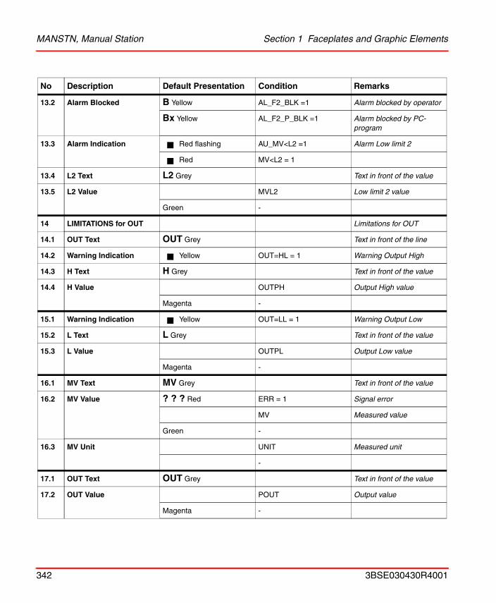
MANSTN, Manual Station Section 1 Faceplates and Graphic Elements
13.2 Alarm Blocked B Yellow AL_F2_BLK =1 Alarm blocked by operator
Bx Yellow AL_F2_P_BLK =1 Alarm blocked by PC-program
13.3 Alarm Indication Red flashing AU_MV<L2 =1 Alarm Low limit 2
Red MV<L2 = 1
13.4 L2 Text L2 Grey Text in front of the value
13.5 L2 Value MVL2 Low limit 2 value
Green -
14 LIMITATIONS for OUT Limitations for OUT
14.1 OUT Text OUT Grey Text in front of the line
14.2 Warning Indication Yellow OUT=HL = 1 Warning Output High
14.3 H Text H Grey Text in front of the value
14.4 H Value OUTPH Output High value
Magenta -
15.1 Warning Indication Yellow OUT=LL = 1 Warning Output Low
15.2 L Text L Grey Text in front of the value
15.3 L Value OUTPL Output Low value
Magenta -
16.1 MV Text MV Grey Text in front of the value
16.2 MV Value ? ? ? Red ERR = 1 Signal error
MV Measured value
Green -
16.3 MV Unit UNIT Measured unit
-
17.1 OUT Text OUT Grey Text in front of the value
17.2 OUT Value POUT Output value
Magenta -
No Description Default Presentation Condition Remarks
342 3BSE030430R4001
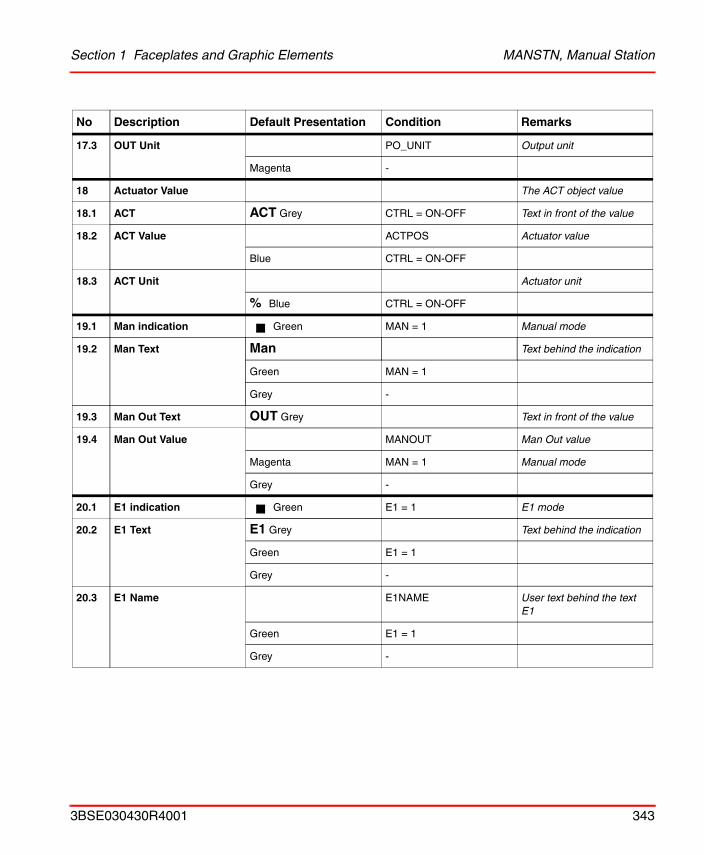
Section 1 Faceplates and Graphic Elements MANSTN, Manual Station
17.3 OUT Unit PO_UNIT Output unit
Magenta -
18 Actuator Value The ACT object value
18.1 ACT ACT Grey CTRL = ON-OFF Text in front of the value
18.2 ACT Value ACTPOS Actuator value
Blue CTRL = ON-OFF
18.3 ACT Unit Actuator unit
% Blue CTRL = ON-OFF
19.1 Man indication Green MAN = 1 Manual mode
19.2 Man Text Man Text behind the indication
Green MAN = 1
Grey -
19.3 Man Out Text OUT Grey Text in front of the value
19.4 Man Out Value MANOUT Man Out value
Magenta MAN = 1 Manual mode
Grey -
20.1 E1 indication Green E1 = 1 E1 mode
20.2 E1 Text E1 Grey Text behind the indication
Green E1 = 1
Grey -
20.3 E1 Name E1NAME User text behind the text E1
Green E1 = 1
Grey -
No Description Default Presentation Condition Remarks
3BSE030430R4001 343
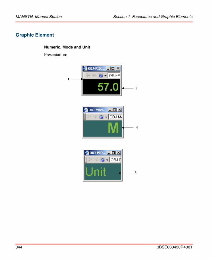
MANSTN, Manual Station Section 1 Faceplates and Graphic Elements
Graphic Element
Numeric, Mode and Unit
Presentation:
1
2
4
3
344 3BSE030430R4001
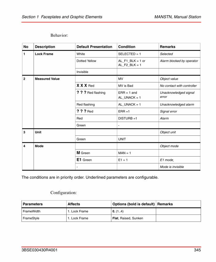
Section 1 Faceplates and Graphic Elements MANSTN, Manual Station
Behavior:
The conditions are in priority order. Underlined parameters are configurable.
Configuration:
No Description Default Presentation Condition Remarks
1 Lock Frame White SELECTED = 1 Selected
Dotted Yellow AL_F1_BLK = 1 orAL_F2_BLK = 1
Alarm blocked by operator
Invisible
2 Measured Value MV Object value
X X X Red MV is Bad No contact with controller
? ? ? Red flashing ERR = 1 and
AL_UNACK = 1
Unacknowledged signal error
Red flashing AL_UNACK = 1 Unacknowledged alarm
? ? ? Red ERR =1 Signal error
Red DISTURB =1 Alarm
Green -
3 Unit Object unit
Green UNIT
4 Mode Object mode
M Green MAN = 1
E1 Green E1 = 1 E1 mode
- Mode is invisible
Parameters Affects Options (bold is default) Remarks
FrameWidth 1. Lock Frame 0, (1..4)
FrameStyle 1. Lock Frame Flat, Raised, Sunken
3BSE030430R4001 345
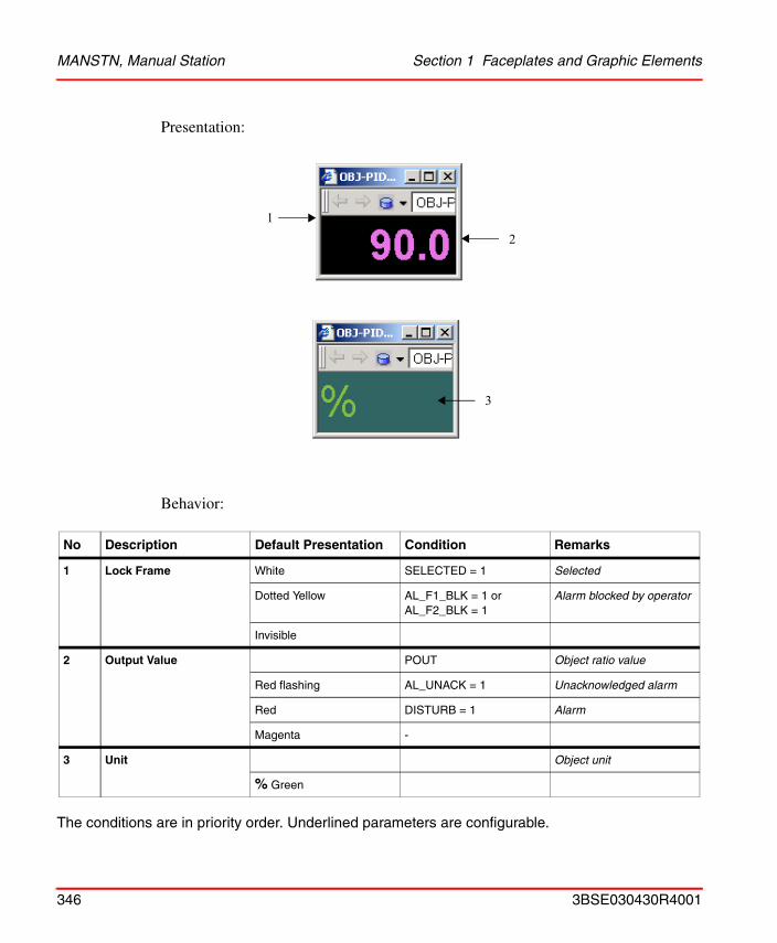
MANSTN, Manual Station Section 1 Faceplates and Graphic Elements
Presentation:
Behavior:
The conditions are in priority order. Underlined parameters are configurable.
No Description Default Presentation Condition Remarks
1 Lock Frame White SELECTED = 1 Selected
Dotted Yellow AL_F1_BLK = 1 orAL_F2_BLK = 1
Alarm blocked by operator
Invisible
2 Output Value POUT Object ratio value
Red flashing AL_UNACK = 1 Unacknowledged alarm
Red DISTURB = 1 Alarm
Magenta -
3 Unit Object unit
% Green
12
3
346 3BSE030430R4001
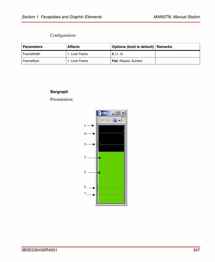
Section 1 Faceplates and Graphic Elements MANSTN, Manual Station
Configuration:
Bargraph
Presentation:
Parameters Affects Options (bold is default) Remarks
FrameWidth 1. Lock Frame 0, (1..4)
FrameStyle 1. Lock Frame Flat, Raised, Sunken
1
3
4
5
2
6
7
3BSE030430R4001 347
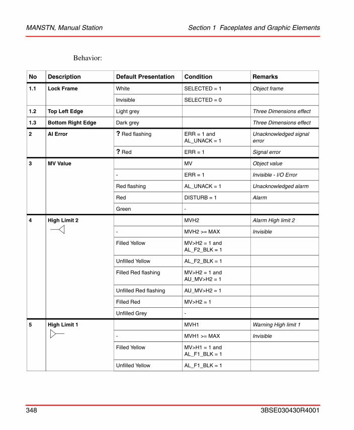
MANSTN, Manual Station Section 1 Faceplates and Graphic Elements
Behavior:
No Description Default Presentation Condition Remarks
1.1 Lock Frame White SELECTED = 1 Object frame
Invisible SELECTED = 0
1.2 Top Left Edge Light grey Three Dimensions effect
1.3 Bottom Right Edge Dark grey Three Dimensions effect
2 AI Error ? Red flashing ERR = 1 andAL_UNACK = 1
Unacknowledged signal error
? Red ERR = 1 Signal error
3 MV Value MV Object value
- ERR = 1 Invisible - I/O Error
Red flashing AL_UNACK = 1 Unacknowledged alarm
Red DISTURB = 1 Alarm
Green -
4 High Limit 2 MVH2 Alarm High limit 2
- MVH2 >= MAX Invisible
Filled Yellow MV>H2 = 1 and AL_F2_BLK = 1
Unfilled Yellow AL_F2_BLK = 1
Filled Red flashing MV>H2 = 1 and AU_MV>H2 = 1
Unfilled Red flashing AU_MV>H2 = 1
Filled Red MV>H2 = 1
Unfilled Grey -
5 High Limit 1 MVH1 Warning High limit 1
- MVH1 >= MAX Invisible
Filled Yellow MV>H1 = 1 and AL_F1_BLK = 1
Unfilled Yellow AL_F1_BLK = 1
348 3BSE030430R4001
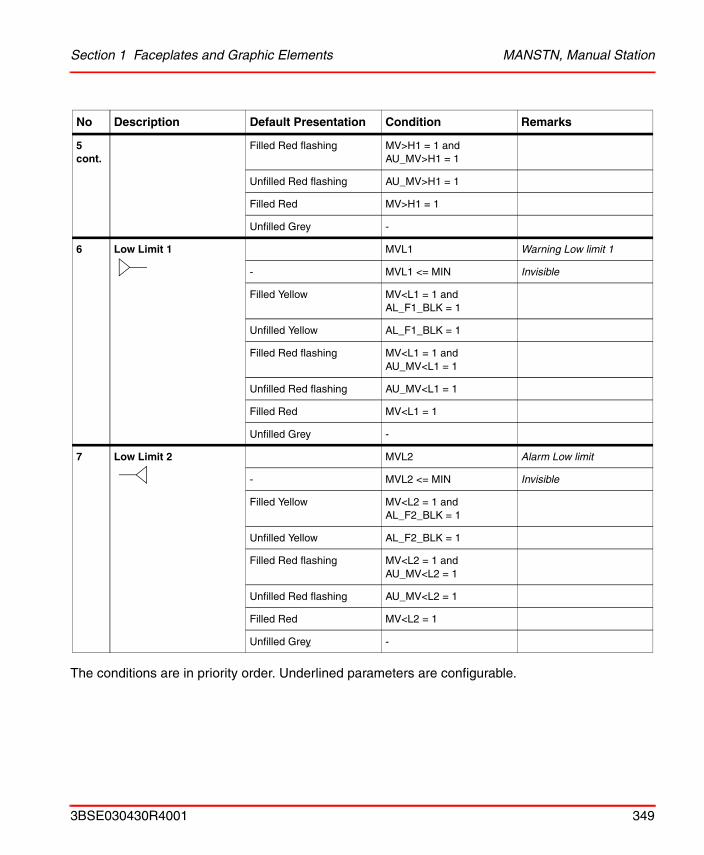
Section 1 Faceplates and Graphic Elements MANSTN, Manual Station
The conditions are in priority order. Underlined parameters are configurable.
5 cont.
Filled Red flashing MV>H1 = 1 and AU_MV>H1 = 1
Unfilled Red flashing AU_MV>H1 = 1
Filled Red MV>H1 = 1
Unfilled Grey -
6 Low Limit 1 MVL1 Warning Low limit 1
- MVL1 <= MIN Invisible
Filled Yellow MV<L1 = 1 and AL_F1_BLK = 1
Unfilled Yellow AL_F1_BLK = 1
Filled Red flashing MV<L1 = 1 and AU_MV<L1 = 1
Unfilled Red flashing AU_MV<L1 = 1
Filled Red MV<L1 = 1
Unfilled Grey -
7 Low Limit 2 MVL2 Alarm Low limit
- MVL2 <= MIN Invisible
Filled Yellow MV<L2 = 1 and AL_F2_BLK = 1
Unfilled Yellow AL_F2_BLK = 1
Filled Red flashing MV<L2 = 1 and AU_MV<L2 = 1
Unfilled Red flashing AU_MV<L2 = 1
Filled Red MV<L2 = 1
Unfilled Grey -
No Description Default Presentation Condition Remarks
3BSE030430R4001 349
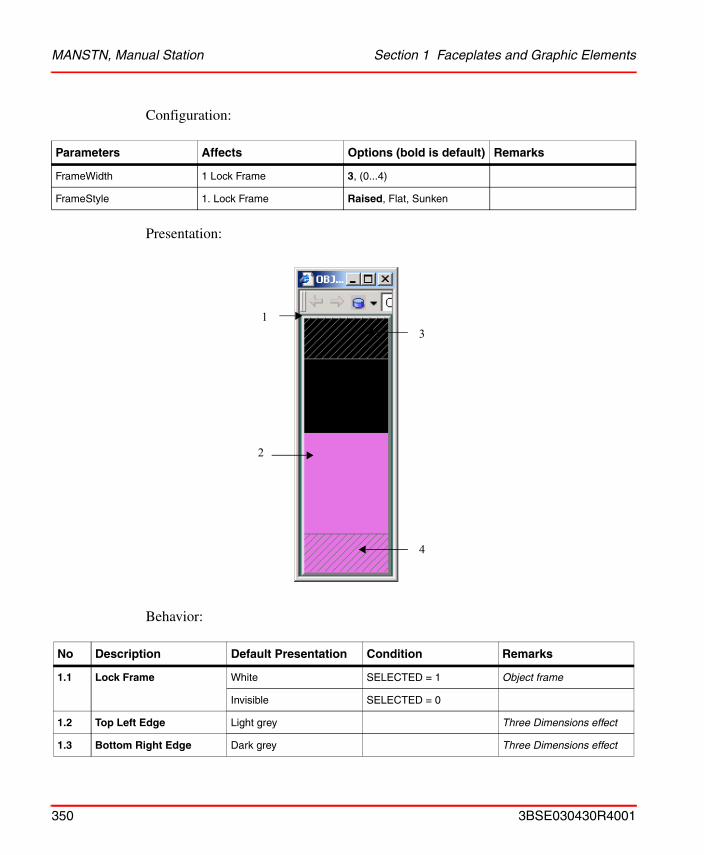
MANSTN, Manual Station Section 1 Faceplates and Graphic Elements
Configuration:
Presentation:
Behavior:
Parameters Affects Options (bold is default) Remarks
FrameWidth 1 Lock Frame 3, (0...4)
FrameStyle 1. Lock Frame Raised, Flat, Sunken
No Description Default Presentation Condition Remarks
1.1 Lock Frame White SELECTED = 1 Object frame
Invisible SELECTED = 0
1.2 Top Left Edge Light grey Three Dimensions effect
1.3 Bottom Right Edge Dark grey Three Dimensions effect
3
4
2
1
350 3BSE030430R4001
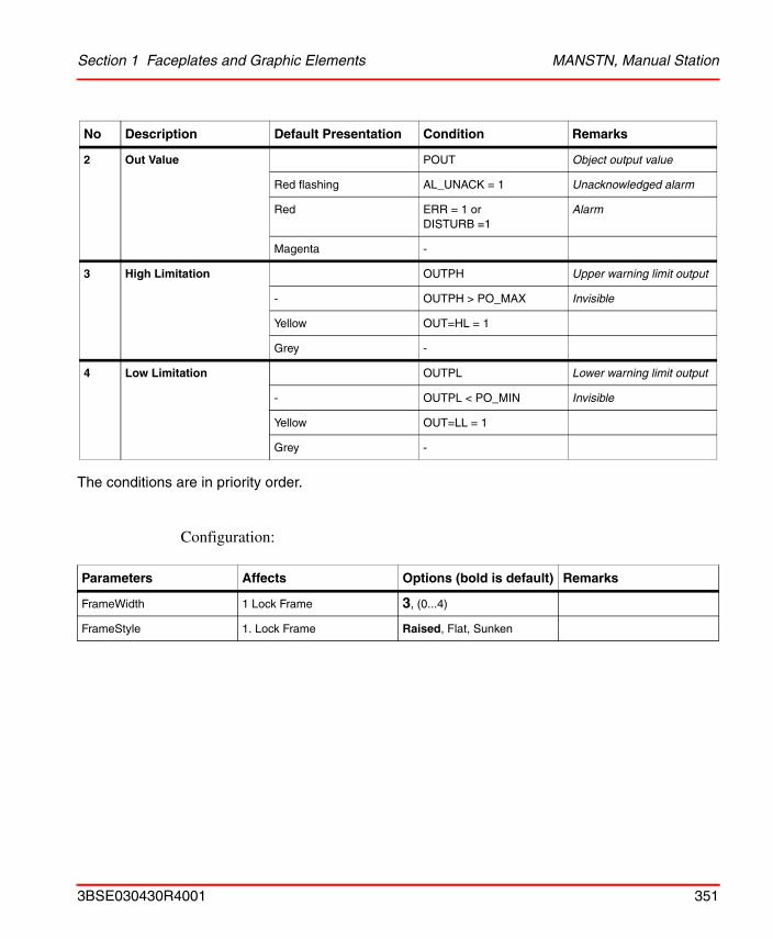
Section 1 Faceplates and Graphic Elements MANSTN, Manual Station
The conditions are in priority order.
Configuration:
2 Out Value POUT Object output value
Red flashing AL_UNACK = 1 Unacknowledged alarm
Red ERR = 1 or DISTURB =1
Alarm
Magenta -
3 High Limitation OUTPH Upper warning limit output
- OUTPH > PO_MAX Invisible
Yellow OUT=HL = 1
Grey -
4 Low Limitation OUTPL Lower warning limit output
- OUTPL < PO_MIN Invisible
Yellow OUT=LL = 1
Grey -
Parameters Affects Options (bold is default) Remarks
FrameWidth 1 Lock Frame 3, (0...4)
FrameStyle 1. Lock Frame Raised, Flat, Sunken
No Description Default Presentation Condition Remarks
3BSE030430R4001 351
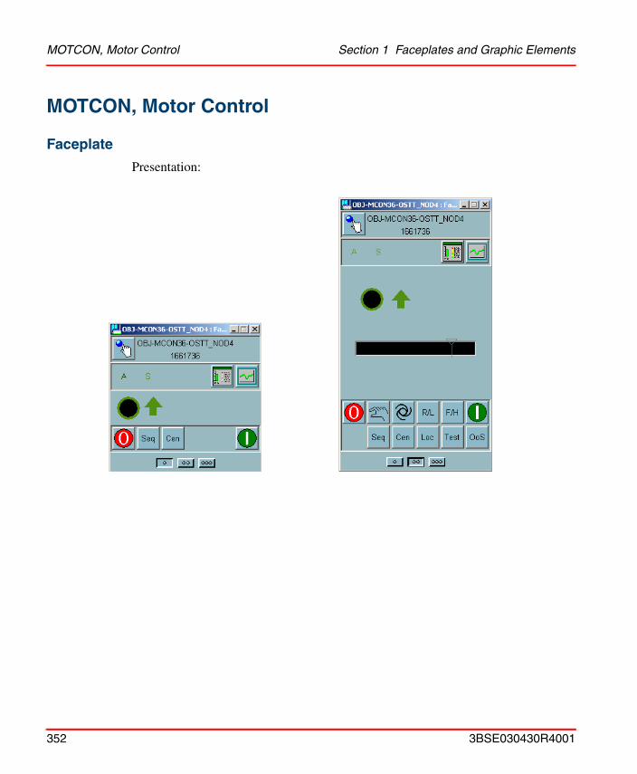
MOTCON, Motor Control Section 1 Faceplates and Graphic Elements
MOTCON, Motor Control
Faceplate
Presentation:
352 3BSE030430R4001
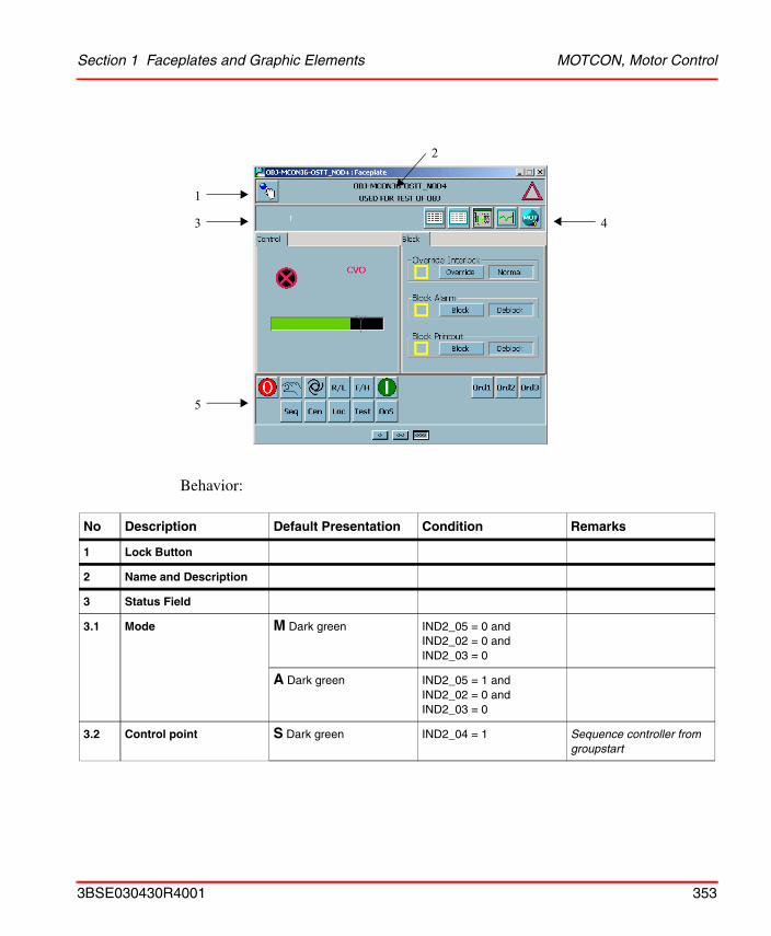
Section 1 Faceplates and Graphic Elements MOTCON, Motor Control
Behavior:
No Description Default Presentation Condition Remarks
1 Lock Button
2 Name and Description
3 Status Field
3.1 Mode M Dark green IND2_05 = 0 and IND2_02 = 0 and IND2_03 = 0
A Dark green IND2_05 = 1 and IND2_02 = 0 and IND2_03 = 0
3.2 Control point S Dark green IND2_04 = 1 Sequence controller from groupstart
1
3
5
4
2
3BSE030430R4001 353
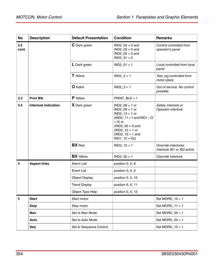
MOTCON, Motor Control Section 1 Faceplates and Graphic Elements
3.2 cont.
C Dark green IND2_04 = 0 and IND2_03 = 0 and IND2_02 = 0 and IND2_01 = 0
Control controlled from operator’s panel
L Dark green IND2_01 = 1 Local controlled from local panel
T Yellow IND2_2 = 1 Test, jog controlled from motor place
O Kakhi IND2_3 = 1 Out of service. No control possible.
3.3 Print Blk P Yellow PRINT_BLK = 1
3.4 Interlock Indication X Dark green IND2_08 = 1 orIND2_09 = 1 orIND2_13 = 1 or(IND2_11 = 1 and IND1_12 = 0) or(IND2_00 = 0 and(IND2_12 = 1 or(IND2_10 = 1 and IND1_12 = 0)))
Safety interlock orOperator interlock
BX Red IND2_15 = 1 Override Interlocks. Interlock IB1 or IB3 active
BX Yellow IND2_00 = 1 Override Interlock
4 Aspect links Alarm List position 0, 0, 8
Event List position 0, 0, 9
Object Display position 5, 5, 10
Trend Display position 6, 6, 11
Object Type Help position 0, 0, 12
5 Start Start motor Set MORD_10 = 1
Stop Stop motor Set MORD_11 = 1
Man Set to Man Mode Set MORD_05 = 1
Auto Set to Auto Mode Set MORD_04 = 1
Seq Set to Sequence Control Set MORD_15 = 1
No Description Default Presentation Condition Remarks
354 3BSE030430R4001
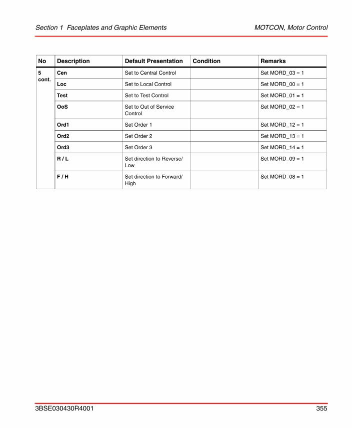
Section 1 Faceplates and Graphic Elements MOTCON, Motor Control
5 cont.
Cen Set to Central Control Set MORD_03 = 1
Loc Set to Local Control Set MORD_00 = 1
Test Set to Test Control Set MORD_01 = 1
OoS Set to Out of Service Control
Set MORD_02 = 1
Ord1 Set Order 1 Set MORD_12 = 1
Ord2 Set Order 2 Set MORD_13 = 1
Ord3 Set Order 3 Set MORD_14 = 1
R / L Set direction to Reverse/ Low
Set MORD_09 = 1
F / H Set direction to Forward/ High
Set MORD_08 = 1
No Description Default Presentation Condition Remarks
3BSE030430R4001 355
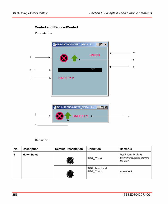
MOTCON, Motor Control Section 1 Faceplates and Graphic Elements
Control and ReducedControl
Presentation:
Behavior:
No Description Default Presentation Condition Remarks
1 Motor Status
IND2_07 = 0
Not Ready for Start Error or interlocks prevent the start
IND2_14 = 1 andIND2_07 = 1 A-Interlock
1
2
3
4
6
5
1
5
3
356 3BSE030430R4001

Section 1 Faceplates and Graphic Elements MOTCON, Motor Control
1 cont.
IND1_12 = 1 orIND1_15 = 1
RunDirection Change
IND2_06 = 1Start Ready Auto. The motor starts when the process conditions are satisfied
IND1_12 = 0 Motor ready to start
Grey IND2_03 = 1 Out of service
Green flashing IND1_15 = 1 Change of Direction in progress
Green -
2.1 Bargraph Green REAL_RES Motor current value
- REAL_RES_HILIM <= 0.1 Bargraph invisible
2.2 Limit Indication at 100% Limit Indication
Yellow AL_BLK = 1 Alarm blocked by operator
Red IND1_10 = 1 High motor current
Grey -
- REAL_RES_HILIM <= 0.1 Limit Indication invisible
3 Act Pres Text ACT_PRES_TEXT Actual interlock text
Red IND2_07 = 0 Not ready for start
Yellow IND2_07 = 1 Ready for start
4 Error 1 CVO Red flashing AU_IND1_00 = 1 Control voltage unack. error
BIM Red flashing AU_IND1_01 = 1 Bimetal Relay unack. error
LSTOP Red flashing AU_IND1_02 = 1 Local stop unack. error
SMON Red flashing AU_IND1_03 = 1 Safety monitor unack. error
CVO Red IND1_00 = 1 Control voltage error
No Description Default Presentation Condition Remarks
3BSE030430R4001 357
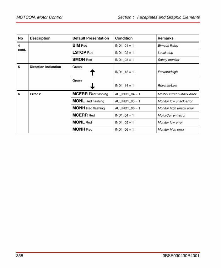
MOTCON, Motor Control Section 1 Faceplates and Graphic Elements
4 cont.
BIM Red IND1_01 = 1 Bimetal Relay
LSTOP Red IND1_02 = 1 Local stop
SMON Red IND1_03 = 1 Safety monitor
5 Direction Indication Green
IND1_13 = 1 Forward/High
Green
IND1_14 = 1 Reverse/Low
6 Error 2 MCERR Red flashing AU_IND1_04 = 1 Motor Current unack error
MONL Red flashing AU_IND1_05 = 1 Monitor low unack error
MONH Red flashing AU_IND1_06 = 1 Monitor high unack error
MCERR Red IND1_04 = 1 MotorCurrent error
MONL Red IND1_05 = 1 Monitor low error
MONH Red IND1_06 = 1 Monitor high error
No Description Default Presentation Condition Remarks
358 3BSE030430R4001
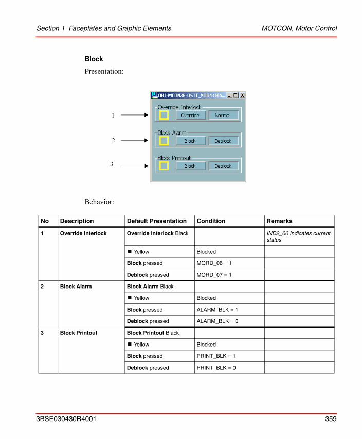
Section 1 Faceplates and Graphic Elements MOTCON, Motor Control
Block
Presentation:
Behavior:
No Description Default Presentation Condition Remarks
1 Override Interlock Override Interlock Black IND2_00 Indicates current status
! Yellow Blocked
Block pressed MORD_06 = 1
Deblock pressed MORD_07 = 1
2 Block Alarm Block Alarm Black
! Yellow Blocked
Block pressed ALARM_BLK = 1
Deblock pressed ALARM_BLK = 0
3 Block Printout Block Printout Black
! Yellow Blocked
Block pressed PRINT_BLK = 1
Deblock pressed PRINT_BLK = 0
1
2
3
3BSE030430R4001 359
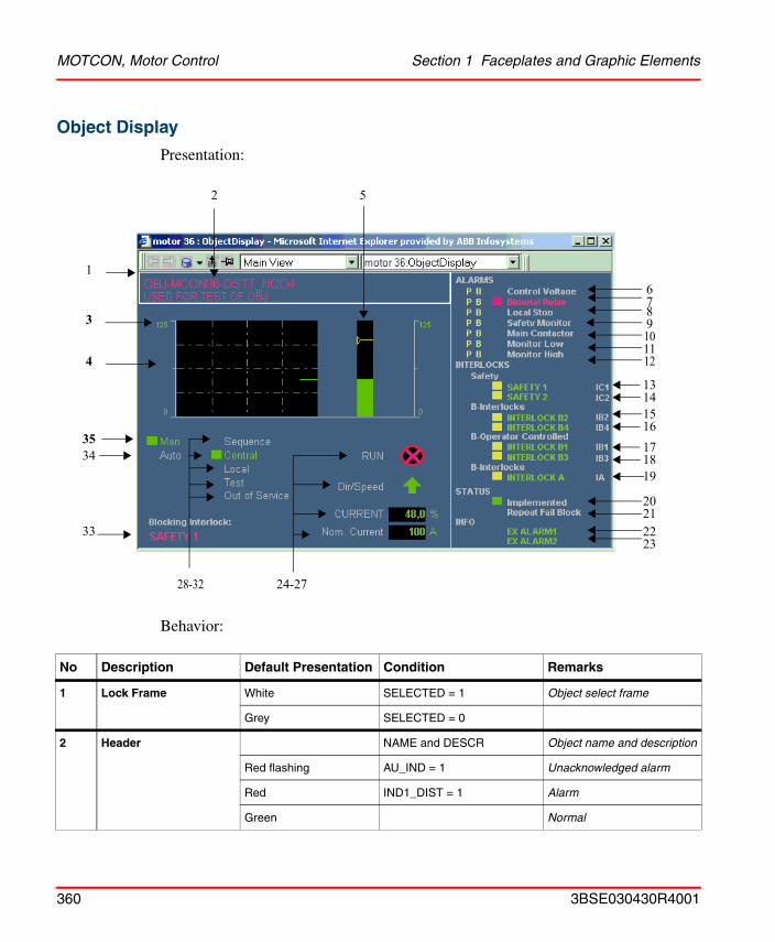
MOTCON, Motor Control Section 1 Faceplates and Graphic Elements
Object Display
Presentation:
Behavior:
No Description Default Presentation Condition Remarks
1 Lock Frame White SELECTED = 1 Object select frame
Grey SELECTED = 0
2 Header NAME and DESCR Object name and description
Red flashing AU_IND = 1 Unacknowledged alarm
Red IND1_DIST = 1 Alarm
Green Normal
1
2 5
24-2728-32
34
7
10
131415
17
19
20212223
89
1112
16
18
3
4
35
33
6
360 3BSE030430R4001
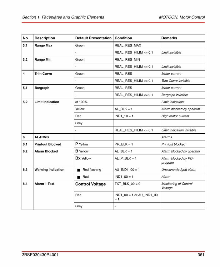
Section 1 Faceplates and Graphic Elements MOTCON, Motor Control
3.1 Range Max Green REAL_RES_MAX
- REAL_RES_HILIM <= 0.1 Limit invisible
3.2 Range Min Green REAL_RES_MIN
- REAL_RES_HILIM <= 0.1 Limit invisible
4 Trim Curve Green REAL_RES Motor current
- REAL_RES_HILIM <= 0.1 Trim Curve invisible
5.1 Bargraph Green REAL_RES Motor current
- REAL_RES_HILIM <= 0.1 Bargraph invisible
5.2 Limit Indication at 100% Limit Indication
Yellow AL_BLK = 1 Alarm blocked by operator
Red IND1_10 = 1 High motor current
Grey
- REAL_RES_HILIM <= 0.1 Limit Indication invisible
6 ALARMS Alarms
6.1 Printout Blocked P Yellow PR_BLK = 1 Printout blocked
6.2 Alarm Blocked B Yellow AL_BLK = 1 Alarm blocked by operator
Bx Yellow AL_P_BLK = 1 Alarm blocked by PC-program
6.3 Warning Indication Red flashing AU_IND1_00 = 1 Unacknowledged alarm
Red IND1_00 = 1 Alarm
6.4 Alarm 1 Text Control Voltage TXT_BLK_00 = 0 Monitoring of Control Voltage
Red IND1_00 = 1 or AU_IND1_00 = 1
Grey -
No Description Default Presentation Condition Remarks
3BSE030430R4001 361
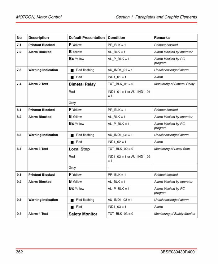
MOTCON, Motor Control Section 1 Faceplates and Graphic Elements
7.1 Printout Blocked P Yellow PR_BLK = 1 Printout blocked
7.2 Alarm Blocked B Yellow AL_BLK = 1 Alarm blocked by operator
Bx Yellow AL_P_BLK = 1 Alarm blocked by PC-program
7.3 Warning Indication Red flashing AU_IND1_01 = 1 Unacknowledged alarm
Red IND1_01 = 1 Alarm
7.4 Alarm 2 Text Bimetal Relay TXT_BLK_01 = 0 Monitoring of Bimetal Relay
Red IND1_01 = 1 or AU_IND1_01 = 1
Grey -
8.1 Printout Blocked P Yellow PR_BLK = 1 Printout blocked
8.2 Alarm Blocked B Yellow AL_BLK = 1 Alarm blocked by operator
Bx Yellow AL_P_BLK = 1 Alarm blocked by PC-program
8.3 Warning Indication Red flashing AU_IND1_02 = 1 Unacknowledged alarm
Red IND1_02 = 1 Alarm
8.4 Alarm 3 Text Local Stop TXT_BLK_02 = 0 Monitoring of Local Stop
Red IND1_02 = 1 or AU_IND1_02 = 1
Grey -
9.1 Printout Blocked P Yellow PR_BLK = 1 Printout blocked
9.2 Alarm Blocked B Yellow AL_BLK = 1 Alarm blocked by operator
Bx Yellow AL_P_BLK = 1 Alarm blocked by PC-program
9.3 Warning Indication Red flashing AU_IND1_03 = 1 Unacknowledged alarm
Red IND1_03 = 1 Alarm
9.4 Alarm 4 Text Safety Monitor TXT_BLK_03 = 0 Monitoring of Safety Monitor
No Description Default Presentation Condition Remarks
362 3BSE030430R4001
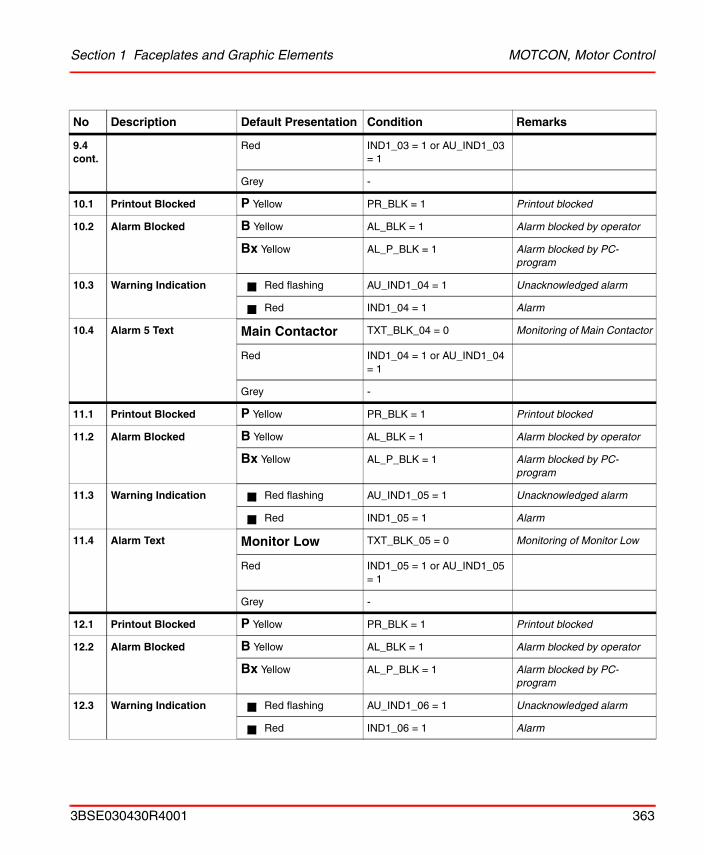
Section 1 Faceplates and Graphic Elements MOTCON, Motor Control
9.4 cont.
Red IND1_03 = 1 or AU_IND1_03 = 1
Grey -
10.1 Printout Blocked P Yellow PR_BLK = 1 Printout blocked
10.2 Alarm Blocked B Yellow AL_BLK = 1 Alarm blocked by operator
Bx Yellow AL_P_BLK = 1 Alarm blocked by PC-program
10.3 Warning Indication Red flashing AU_IND1_04 = 1 Unacknowledged alarm
Red IND1_04 = 1 Alarm
10.4 Alarm 5 Text Main Contactor TXT_BLK_04 = 0 Monitoring of Main Contactor
Red IND1_04 = 1 or AU_IND1_04 = 1
Grey -
11.1 Printout Blocked P Yellow PR_BLK = 1 Printout blocked
11.2 Alarm Blocked B Yellow AL_BLK = 1 Alarm blocked by operator
Bx Yellow AL_P_BLK = 1 Alarm blocked by PC-program
11.3 Warning Indication Red flashing AU_IND1_05 = 1 Unacknowledged alarm
Red IND1_05 = 1 Alarm
11.4 Alarm Text Monitor Low TXT_BLK_05 = 0 Monitoring of Monitor Low
Red IND1_05 = 1 or AU_IND1_05 = 1
Grey -
12.1 Printout Blocked P Yellow PR_BLK = 1 Printout blocked
12.2 Alarm Blocked B Yellow AL_BLK = 1 Alarm blocked by operator
Bx Yellow AL_P_BLK = 1 Alarm blocked by PC-program
12.3 Warning Indication Red flashing AU_IND1_06 = 1 Unacknowledged alarm
Red IND1_06 = 1 Alarm
No Description Default Presentation Condition Remarks
3BSE030430R4001 363
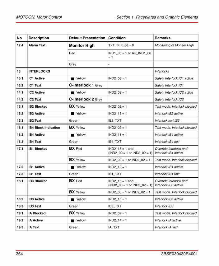
MOTCON, Motor Control Section 1 Faceplates and Graphic Elements
12.4 Alarm Text Monitor High TXT_BLK_06 = 0 Monitoring of Monitor High
Red IND1_06 = 1 or AU_IND1_06 = 1
Grey -
13 INTERLOCKS Interlocks
13.1 IC1 Active Yellow IND2_08 = 1 Safety Interlock IC1 active
13.2 IC1 Text C-Interlock 1 Grey Safety Interlock IC1
14.1 IC2 Active Yellow IND2_09 = 1 Safety Interlock IC2 active
14.2 IC2 Text C-Interlock 2 Grey Safety Interlock IC2
15.1 IB2 Blocked BX Yellow IND2_02 = 1 Test mode. Interlock blocked
15.2 IB2 Active Yellow IND2_13 = 1 Interlock IB2 active
15.3 IB2 Text Green IB2_TXT Interlock text IB2
16.1 IB4 Block Indication BX Yellow IND2_02 = 1 Test mode. Interlock blocked
16.2 IB4 Active Yellow IND2_11 = 1 Interlock IB4 active
16.3 IB4 Text Green IB4_TXT Interlock IB4 text
17.1 IB1 Blocked BX Red IND2_15 = 1 and(IND2_00 = 1 or IND2_02 = 1)
Override Interlock and Interlock IB1 active
BX Yellow IND2_00 = 1 or IND2_02 = 1 Test mode. Interlock blocked
17.2 IB1 Active Yellow IND2_12 = 1 Interlock IB1 active
17.3 IB1 Text Green IB1_TXT Interlock IB1 text
18.1 IB3 Blocked BX Red IND2_15 = 1 and(IND2_00 = 1 or IND2_02 = 1)
Override Interlock and Interlock IB3 active
BX Yellow IND2_00 = 1 or IND2_02 = 1 Test mode. Interlock blocked
18.2 IB3 Active Yellow IND2_10 = 1 Interlock IB3 active
18.3 IB3 Text Green IB3_TXT Interlock IB3
19.1 IA Blocked BX Yellow IND2_02 = 1 Test mode. Interlock blocked
19.2 IA Active Yellow IND2_14 = 1 Interlock IA active
19.3 IA Text Green IA_TXT Interlock IA text
No Description Default Presentation Condition Remarks
364 3BSE030430R4001
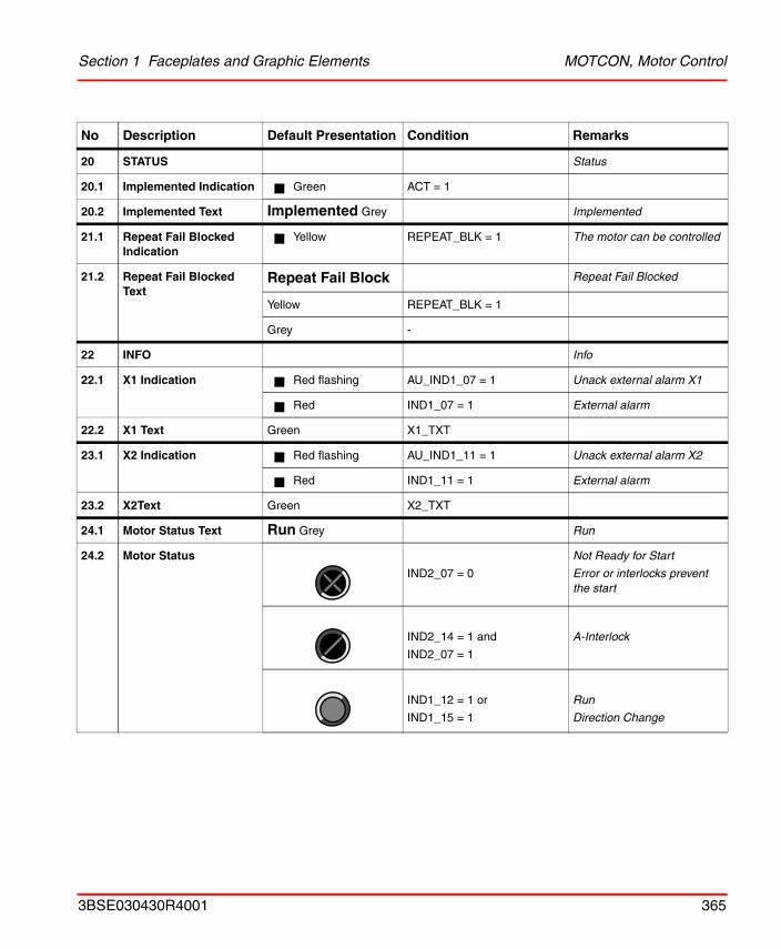
Section 1 Faceplates and Graphic Elements MOTCON, Motor Control
20 STATUS Status
20.1 Implemented Indication Green ACT = 1
20.2 Implemented Text Implemented Grey Implemented
21.1 Repeat Fail Blocked Indication
Yellow REPEAT_BLK = 1 The motor can be controlled
21.2 Repeat Fail Blocked Text
Repeat Fail Block Repeat Fail Blocked
Yellow REPEAT_BLK = 1
Grey -
22 INFO Info
22.1 X1 Indication Red flashing AU_IND1_07 = 1 Unack external alarm X1
Red IND1_07 = 1 External alarm
22.2 X1 Text Green X1_TXT
23.1 X2 Indication Red flashing AU_IND1_11 = 1 Unack external alarm X2
Red IND1_11 = 1 External alarm
23.2 X2Text Green X2_TXT
24.1 Motor Status Text Run Grey Run
24.2 Motor Status
IND2_07 = 0
Not Ready for Start
Error or interlocks prevent the start
IND2_14 = 1 and
IND2_07 = 1
A-Interlock
IND1_12 = 1 or
IND1_15 = 1
Run
Direction Change
No Description Default Presentation Condition Remarks
3BSE030430R4001 365
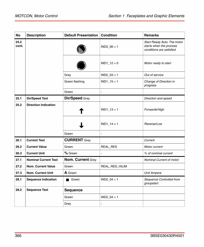
MOTCON, Motor Control Section 1 Faceplates and Graphic Elements
24.2 cont. IND2_06 = 1
Start Ready Auto. The motor starts when the process conditions are satisfied
IND1_12 = 0 Motor ready to start
Grey IND2_03 = 1 Out of service
Green flashing IND1_15 = 1 Change of Direction in progress
Green -
25.1 Dir/Speed Text Dir/Speed Grey Direction and speed
25.2 Direction Indication
IND1_13 = 1 Forwards/High
IND1_14 = 1 Reverse/Low
Green -
26.1 Current Text CURRENT Grey Current
26.2 Current Value Green REAL_RES Motor current
26.3 Current Unit % Green - % of nominal current
27.1 Nominal Current Text Nom. Current Grey Nominal Current of motor
27.2 Nom. Current Value Green REAL_RES_HILIM
27.3 Nom. Current Unit A Green Unit Ampere
28.1 Sequence Indication Green IND2_04 = 1 Sequence Controlled from groupstart
28.2 Sequence Text Sequence
Green IND2_04 = 1
Grey -
No Description Default Presentation Condition Remarks
366 3BSE030430R4001
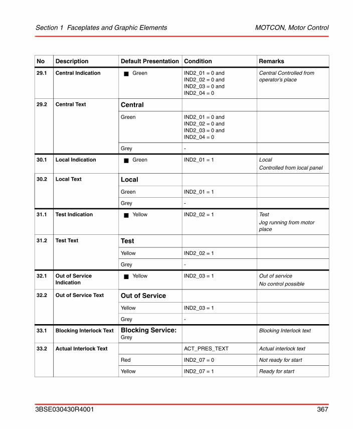
Section 1 Faceplates and Graphic Elements MOTCON, Motor Control
29.1 Central Indication Green IND2_01 = 0 andIND2_02 = 0 andIND2_03 = 0 andIND2_04 = 0
Central Controlled from operator’s place
29.2 Central Text Central
Green IND2_01 = 0 andIND2_02 = 0 andIND2_03 = 0 andIND2_04 = 0
Grey -
30.1 Local Indication Green IND2_01 = 1 Local
Controlled from local panel
30.2 Local Text Local
Green IND2_01 = 1
Grey -
31.1 Test Indication Yellow IND2_02 = 1 Test
Jog running from motor place
31.2 Test Text Test
Yellow IND2_02 = 1
Grey -
32.1 Out of Service Indication
Yellow IND2_03 = 1 Out of service
No control possible
32.2 Out of Service Text Out of Service
Yellow IND2_03 = 1
Grey -
33.1 Blocking Interlock Text Blocking Service: Grey
Blocking Interlock text
33.2 Actual Interlock Text ACT_PRES_TEXT Actual interlock text
Red IND2_07 = 0 Not ready for start
Yellow IND2_07 = 1 Ready for start
No Description Default Presentation Condition Remarks
3BSE030430R4001 367
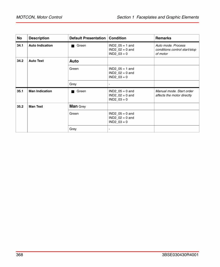
MOTCON, Motor Control Section 1 Faceplates and Graphic Elements
34.1 Auto Indication Green IND2_05 = 1 andIND2_02 = 0 andIND2_03 = 0
Auto mode. Process conditions control start/stop of motor
34.2 Auto Text Auto
Green IND2_05 = 1 andIND2_02 = 0 andIND2_03 = 0
Grey -
35.1 Man Indication Green IND2_05 = 0 andIND2_02 = 0 andIND2_03 = 0
Manual mode. Start order affects the motor directly
35.2 Man Text Man Grey
Green IND2_05 = 0 andIND2_02 = 0 andIND2_03 = 0
Grey -
No Description Default Presentation Condition Remarks
368 3BSE030430R4001
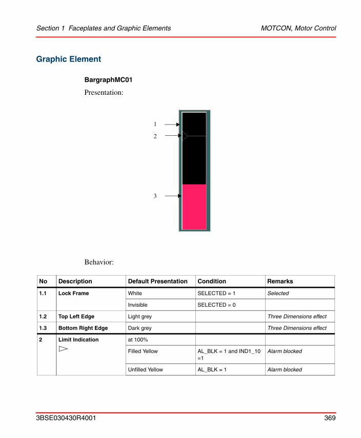
Section 1 Faceplates and Graphic Elements MOTCON, Motor Control
Graphic Element
BargraphMC01
Presentation:
Behavior:
No Description Default Presentation Condition Remarks
1.1 Lock Frame White SELECTED = 1 Selected
Invisible SELECTED = 0
1.2 Top Left Edge Light grey Three Dimensions effect
1.3 Bottom Right Edge Dark grey Three Dimensions effect
2 Limit Indication at 100%
Filled Yellow AL_BLK = 1 and IND1_10 =1
Alarm blocked
Unfilled Yellow AL_BLK = 1 Alarm blocked
1
2
3
3BSE030430R4001 369
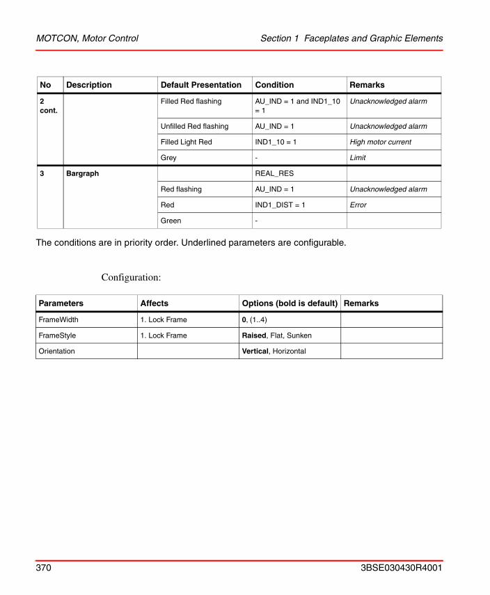
MOTCON, Motor Control Section 1 Faceplates and Graphic Elements
The conditions are in priority order. Underlined parameters are configurable.
Configuration:
2 cont.
Filled Red flashing AU_IND = 1 and IND1_10 = 1
Unacknowledged alarm
Unfilled Red flashing AU_IND = 1 Unacknowledged alarm
Filled Light Red IND1_10 = 1 High motor current
Grey - Limit
3 Bargraph REAL_RES
Red flashing AU_IND = 1 Unacknowledged alarm
Red IND1_DIST = 1 Error
Green -
Parameters Affects Options (bold is default) Remarks
FrameWidth 1. Lock Frame 0, (1..4)
FrameStyle 1. Lock Frame Raised, Flat, Sunken
Orientation Vertical, Horizontal
No Description Default Presentation Condition Remarks
370 3BSE030430R4001

Section 1 Faceplates and Graphic Elements MOTCON, Motor Control
Motor01
Presentation:
Behavior:
No Description Default Presentation Condition Remarks
1 Lock Frame White SELECTED = 1 Selected
Yellow IND2_00 = 1 Interlock override by operator
Dotted Yellow AL_BLK = 1 Alarm blocked by operator
Invisible -
2 Mode orControl point
ModeIndVis = true You can configure your own text instead of using the figures
* Yellow IND2_02 = 1 and IND2_03 = 0
Test
A Green IND2_05 = 1 andIND2_02 = 0 andIND2_03 = 0
Auto mode
1
4
32
3BSE030430R4001 371
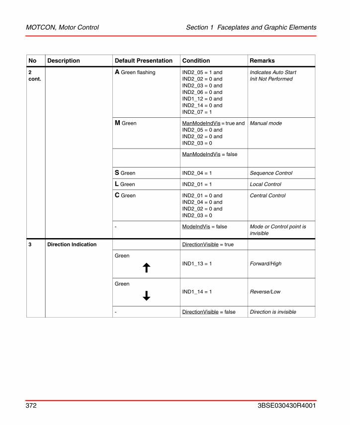
MOTCON, Motor Control Section 1 Faceplates and Graphic Elements
2 cont.
A Green flashing IND2_05 = 1 andIND2_02 = 0 andIND2_03 = 0 andIND2_06 = 0 andIND1_12 = 0 andIND2_14 = 0 andIND2_07 = 1
Indicates Auto StartInit Not Performed
M Green ManModeIndVis = true and IND2_05 = 0 andIND2_02 = 0 andIND2_03 = 0
Manual mode
ManModeIndVis = false
S Green IND2_04 = 1 Sequence Control
L Green IND2_01 = 1 Local Control
C Green IND2_01 = 0 and IND2_04 = 0 and IND2_02 = 0 andIND2_03 = 0
Central Control
- ModeIndVis = false Mode or Control point is invisible
3 Direction Indication DirectionVisible = true
Green
IND1_13 = 1 Forward/High
Green
IND1_14 = 1 Reverse/Low
- DirectionVisible = false Direction is invisible
No Description Default Presentation Condition Remarks
372 3BSE030430R4001
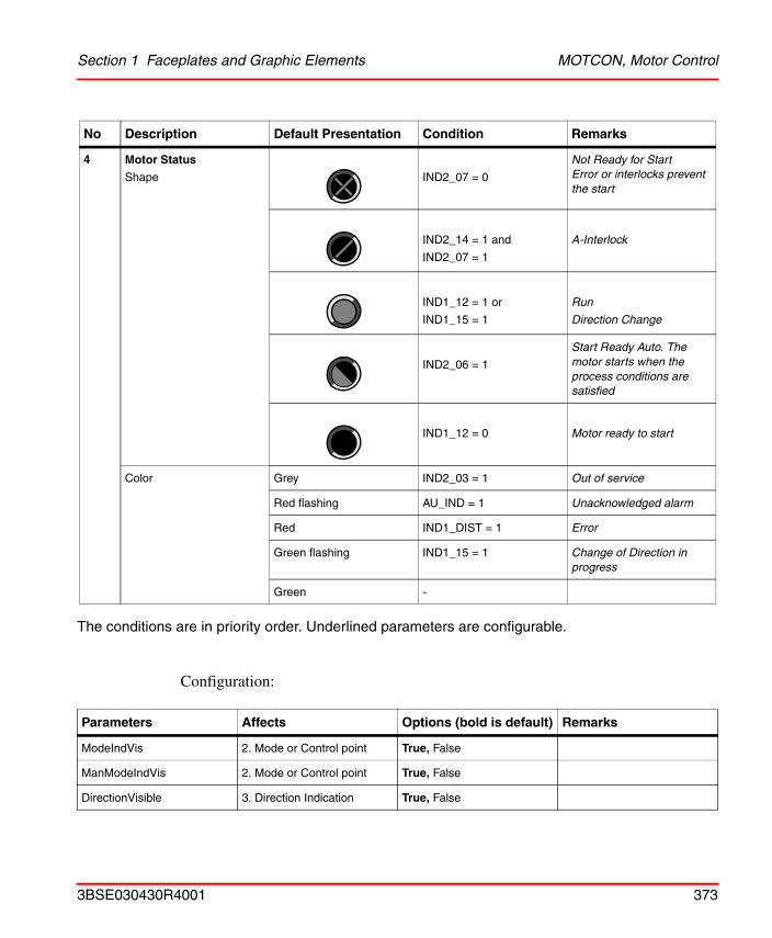
Section 1 Faceplates and Graphic Elements MOTCON, Motor Control
The conditions are in priority order. Underlined parameters are configurable.
Configuration:
4 Motor Status
Shape IND2_07 = 0
Not Ready for StartError or interlocks prevent the start
IND2_14 = 1 and
IND2_07 = 1
A-Interlock
IND1_12 = 1 or
IND1_15 = 1
Run
Direction Change
IND2_06 = 1
Start Ready Auto. The motor starts when the process conditions are satisfied
IND1_12 = 0 Motor ready to start
Color Grey IND2_03 = 1 Out of service
Red flashing AU_IND = 1 Unacknowledged alarm
Red IND1_DIST = 1 Error
Green flashing IND1_15 = 1 Change of Direction in progress
Green -
Parameters Affects Options (bold is default) Remarks
ModeIndVis 2. Mode or Control point True, False
ManModeIndVis 2. Mode or Control point True, False
DirectionVisible 3. Direction Indication True, False
No Description Default Presentation Condition Remarks
3BSE030430R4001 373
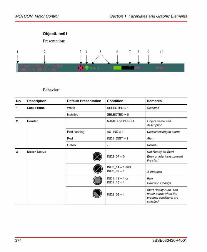
MOTCON, Motor Control Section 1 Faceplates and Graphic Elements
ObjectLine01
Presentation:
Behavior:
No Description Default Presentation Condition Remarks
1 Lock Frame White SELECTED = 1 Selected
Invisible SELECTED = 0
2 Header NAME and DESCR Object name and description
Red flashing AU_IND = 1 Unacknowledged alarm
Red IND1_DIST = 1 Alarm
Green - Normal
3 Motor Status
IND2_07 = 0
Not Ready for Start
Error or interlocks prevent the start
IND2_14 = 1 andIND2_07 = 1 A-Interlock
IND1_12 = 1 orIND1_15 = 1
Run
Direction Change
IND2_06 = 1
Start Ready Auto. The motor starts when the process conditions are satisfied
1 2 3 4 5 6 7 8 9 10
374 3BSE030430R4001
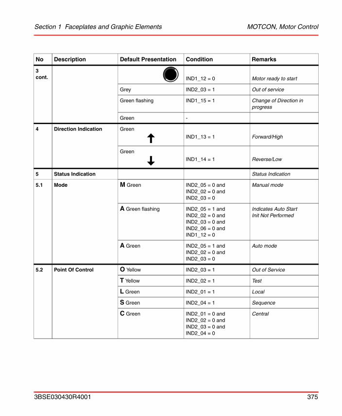
Section 1 Faceplates and Graphic Elements MOTCON, Motor Control
3 cont. IND1_12 = 0 Motor ready to start
Grey IND2_03 = 1 Out of service
Green flashing IND1_15 = 1 Change of Direction in progress
Green -
4 Direction Indication Green
IND1_13 = 1 Forward/High
Green
IND1_14 = 1 Reverse/Low
5 Status Indication Status Indication
5.1 Mode M Green IND2_05 = 0 andIND2_02 = 0 andIND2_03 = 0
Manual mode
A Green flashing IND2_05 = 1 andIND2_02 = 0 andIND2_03 = 0 andIND2_06 = 0 andIND1_12 = 0
Indicates Auto StartInit Not Performed
A Green IND2_05 = 1 andIND2_02 = 0 andIND2_03 = 0
Auto mode
5.2 Point Of Control O Yellow IND2_03 = 1 Out of Service
T Yellow IND2_02 = 1 Test
L Green IND2_01 = 1 Local
S Green IND2_04 = 1 Sequence
C Green IND2_01 = 0 andIND2_02 = 0 andIND2_03 = 0 andIND2_04 = 0
Central
No Description Default Presentation Condition Remarks
3BSE030430R4001 375
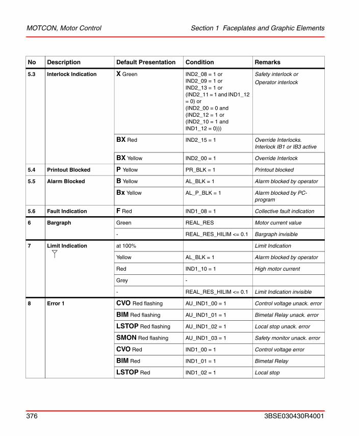
MOTCON, Motor Control Section 1 Faceplates and Graphic Elements
5.3 Interlock Indication X Green IND2_08 = 1 orIND2_09 = 1 orIND2_13 = 1 or(IND2_11 = 1 and IND1_12 = 0) or(IND2_00 = 0 and(IND2_12 = 1 or(IND2_10 = 1 and IND1_12 = 0)))
Safety interlock or
Operator interlock
BX Red IND2_15 = 1 Override Interlocks. Interlock IB1 or IB3 active
BX Yellow IND2_00 = 1 Override Interlock
5.4 Printout Blocked P Yellow PR_BLK = 1 Printout blocked
5.5 Alarm Blocked B Yellow AL_BLK = 1 Alarm blocked by operator
Bx Yellow AL_P_BLK = 1 Alarm blocked by PC-program
5.6 Fault Indication F Red IND1_08 = 1 Collective fault indication
6 Bargraph Green REAL_RES Motor current value
- REAL_RES_HILIM <= 0.1 Bargraph invisible
7 Limit Indication at 100% Limit Indication
Yellow AL_BLK = 1 Alarm blocked by operator
Red IND1_10 = 1 High motor current
Grey -
- REAL_RES_HILIM <= 0.1 Limit Indication invisible
8 Error 1 CVO Red flashing AU_IND1_00 = 1 Control voltage unack. error
BIM Red flashing AU_IND1_01 = 1 Bimetal Relay unack. error
LSTOP Red flashing AU_IND1_02 = 1 Local stop unack. error
SMON Red flashing AU_IND1_03 = 1 Safety monitor unack. error
CVO Red IND1_00 = 1 Control voltage error
BIM Red IND1_01 = 1 Bimetal Relay
LSTOP Red IND1_02 = 1 Local stop
No Description Default Presentation Condition Remarks
376 3BSE030430R4001
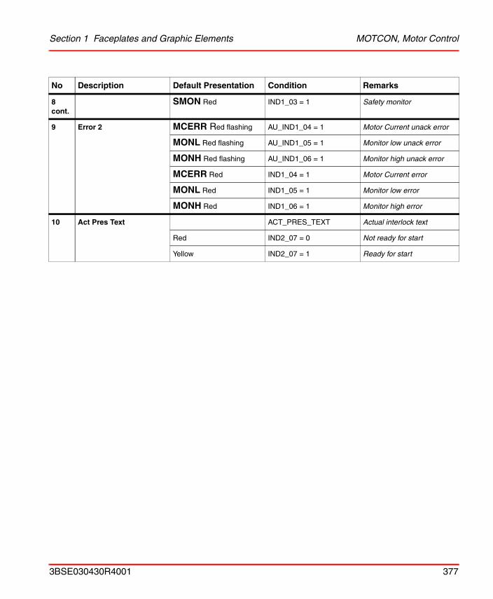
Section 1 Faceplates and Graphic Elements MOTCON, Motor Control
8 cont.
SMON Red IND1_03 = 1 Safety monitor
9 Error 2 MCERR Red flashing AU_IND1_04 = 1 Motor Current unack error
MONL Red flashing AU_IND1_05 = 1 Monitor low unack error
MONH Red flashing AU_IND1_06 = 1 Monitor high unack error
MCERR Red IND1_04 = 1 Motor Current error
MONL Red IND1_05 = 1 Monitor low error
MONH Red IND1_06 = 1 Monitor high error
10 Act Pres Text ACT_PRES_TEXT Actual interlock text
Red IND2_07 = 0 Not ready for start
Yellow IND2_07 = 1 Ready for start
No Description Default Presentation Condition Remarks
3BSE030430R4001 377
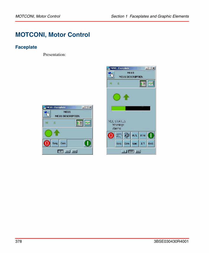
MOTCONI, Motor Control Section 1 Faceplates and Graphic Elements
MOTCONI, Motor Control
Faceplate
Presentation:
378 3BSE030430R4001
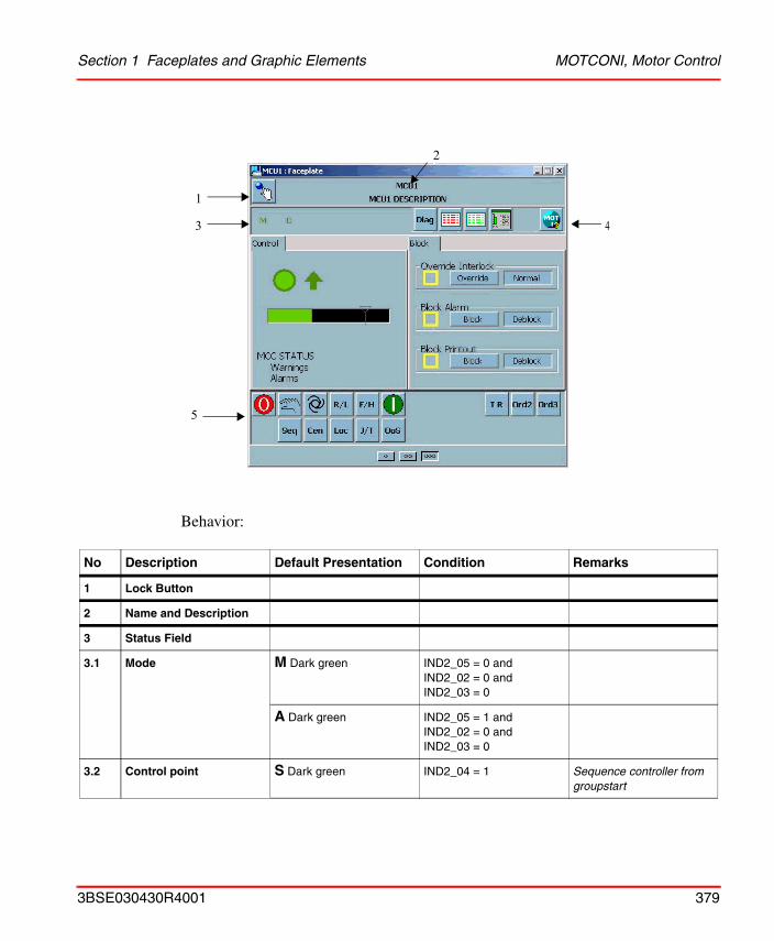
Section 1 Faceplates and Graphic Elements MOTCONI, Motor Control
Behavior:
No Description Default Presentation Condition Remarks
1 Lock Button
2 Name and Description
3 Status Field
3.1 Mode M Dark green IND2_05 = 0 and IND2_02 = 0 and IND2_03 = 0
A Dark green IND2_05 = 1 and IND2_02 = 0 and IND2_03 = 0
3.2 Control point S Dark green IND2_04 = 1 Sequence controller from groupstart
1
3
5
4
2
3BSE030430R4001 379
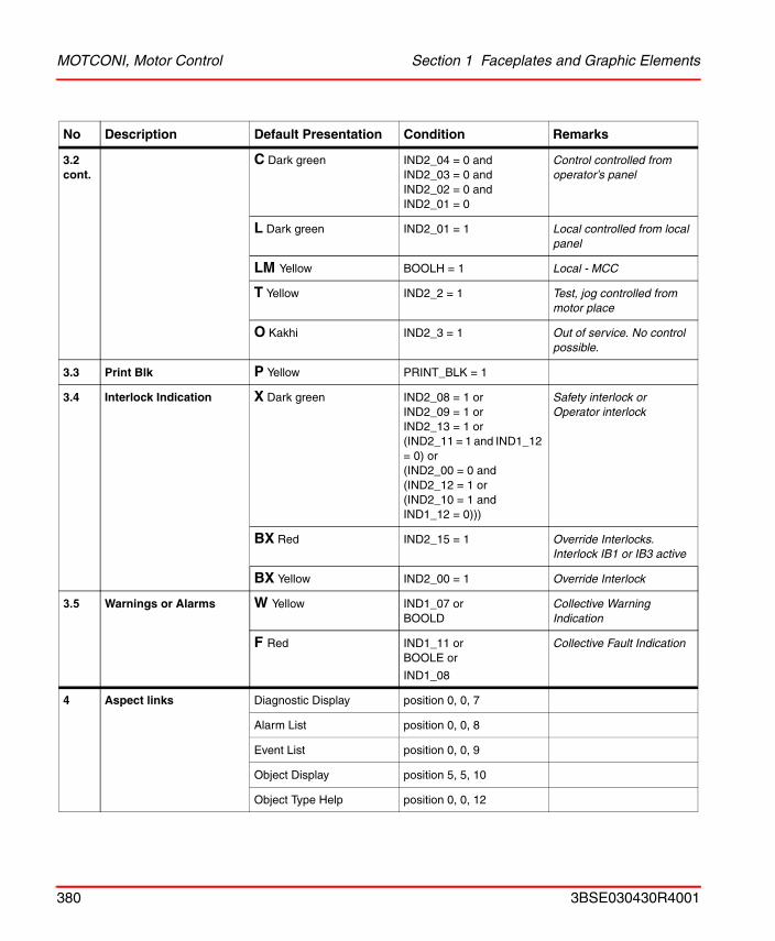
MOTCONI, Motor Control Section 1 Faceplates and Graphic Elements
3.2 cont.
C Dark green IND2_04 = 0 and IND2_03 = 0 and IND2_02 = 0 and IND2_01 = 0
Control controlled from operator’s panel
L Dark green IND2_01 = 1 Local controlled from local panel
LM Yellow BOOLH = 1 Local - MCC
T Yellow IND2_2 = 1 Test, jog controlled from motor place
O Kakhi IND2_3 = 1 Out of service. No control possible.
3.3 Print Blk P Yellow PRINT_BLK = 1
3.4 Interlock Indication X Dark green IND2_08 = 1 orIND2_09 = 1 orIND2_13 = 1 or(IND2_11 = 1 and IND1_12 = 0) or(IND2_00 = 0 and(IND2_12 = 1 or(IND2_10 = 1 and IND1_12 = 0)))
Safety interlock orOperator interlock
BX Red IND2_15 = 1 Override Interlocks. Interlock IB1 or IB3 active
BX Yellow IND2_00 = 1 Override Interlock
3.5 Warnings or Alarms W Yellow IND1_07 orBOOLD
Collective Warning Indication
F Red IND1_11 orBOOLE or
IND1_08
Collective Fault Indication
4 Aspect links Diagnostic Display position 0, 0, 7
Alarm List position 0, 0, 8
Event List position 0, 0, 9
Object Display position 5, 5, 10
Object Type Help position 0, 0, 12
No Description Default Presentation Condition Remarks
380 3BSE030430R4001
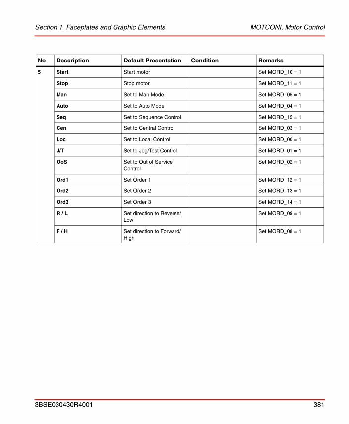
Section 1 Faceplates and Graphic Elements MOTCONI, Motor Control
5 Start Start motor Set MORD_10 = 1
Stop Stop motor Set MORD_11 = 1
Man Set to Man Mode Set MORD_05 = 1
Auto Set to Auto Mode Set MORD_04 = 1
Seq Set to Sequence Control Set MORD_15 = 1
Cen Set to Central Control Set MORD_03 = 1
Loc Set to Local Control Set MORD_00 = 1
J/T Set to Jog/Test Control Set MORD_01 = 1
OoS Set to Out of Service Control
Set MORD_02 = 1
Ord1 Set Order 1 Set MORD_12 = 1
Ord2 Set Order 2 Set MORD_13 = 1
Ord3 Set Order 3 Set MORD_14 = 1
R / L Set direction to Reverse/ Low
Set MORD_09 = 1
F / H Set direction to Forward/ High
Set MORD_08 = 1
No Description Default Presentation Condition Remarks
3BSE030430R4001 381
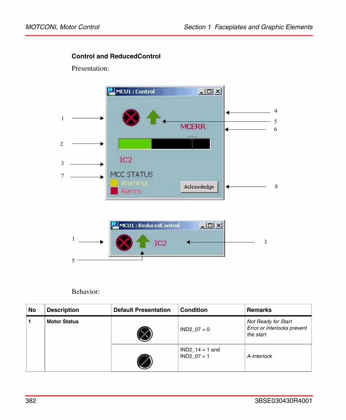
MOTCONI, Motor Control Section 1 Faceplates and Graphic Elements
Control and ReducedControl
Presentation:
Behavior:
No Description Default Presentation Condition Remarks
1 Motor Status
IND2_07 = 0
Not Ready for Start Error or interlocks prevent the start
IND2_14 = 1 andIND2_07 = 1 A-Interlock
1
2
4
65
7
3
8
1
5
3
382 3BSE030430R4001
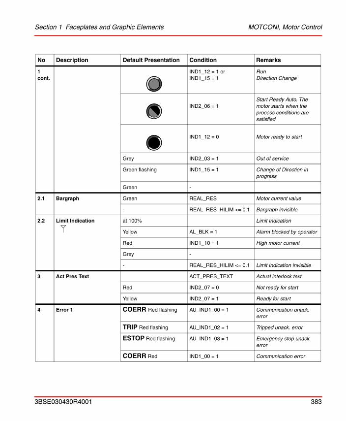
Section 1 Faceplates and Graphic Elements MOTCONI, Motor Control
1 cont.
IND1_12 = 1 orIND1_15 = 1
RunDirection Change
IND2_06 = 1Start Ready Auto. The motor starts when the process conditions are satisfied
IND1_12 = 0 Motor ready to start
Grey IND2_03 = 1 Out of service
Green flashing IND1_15 = 1 Change of Direction in progress
Green -
2.1 Bargraph Green REAL_RES Motor current value
- REAL_RES_HILIM <= 0.1 Bargraph invisible
2.2 Limit Indication at 100% Limit Indication
Yellow AL_BLK = 1 Alarm blocked by operator
Red IND1_10 = 1 High motor current
Grey -
- REAL_RES_HILIM <= 0.1 Limit Indication invisible
3 Act Pres Text ACT_PRES_TEXT Actual interlock text
Red IND2_07 = 0 Not ready for start
Yellow IND2_07 = 1 Ready for start
4 Error 1 COERR Red flashing AU_IND1_00 = 1 Communication unack. error
TRIP Red flashing AU_IND1_02 = 1 Tripped unack. error
ESTOP Red flashing AU_IND1_03 = 1 Emergency stop unack. error
COERR Red IND1_00 = 1 Communication error
No Description Default Presentation Condition Remarks
3BSE030430R4001 383
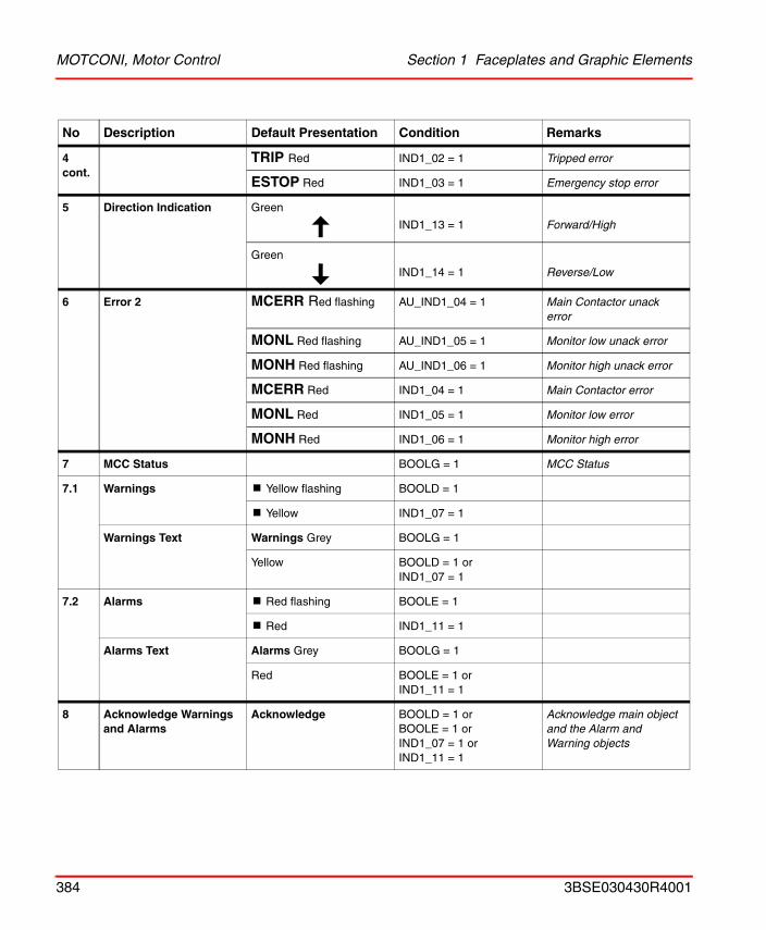
MOTCONI, Motor Control Section 1 Faceplates and Graphic Elements
4 cont.
TRIP Red IND1_02 = 1 Tripped error
ESTOP Red IND1_03 = 1 Emergency stop error
5 Direction Indication Green
IND1_13 = 1 Forward/High
Green
IND1_14 = 1 Reverse/Low
6 Error 2 MCERR Red flashing AU_IND1_04 = 1 Main Contactor unack error
MONL Red flashing AU_IND1_05 = 1 Monitor low unack error
MONH Red flashing AU_IND1_06 = 1 Monitor high unack error
MCERR Red IND1_04 = 1 Main Contactor error
MONL Red IND1_05 = 1 Monitor low error
MONH Red IND1_06 = 1 Monitor high error
7 MCC Status BOOLG = 1 MCC Status
7.1 Warnings ! Yellow flashing BOOLD = 1
! Yellow IND1_07 = 1
Warnings Text Warnings Grey BOOLG = 1
Yellow BOOLD = 1 orIND1_07 = 1
7.2 Alarms ! Red flashing BOOLE = 1
! Red IND1_11 = 1
Alarms Text Alarms Grey BOOLG = 1
Red BOOLE = 1 orIND1_11 = 1
8 Acknowledge Warnings and Alarms
Acknowledge BOOLD = 1 orBOOLE = 1 orIND1_07 = 1 orIND1_11 = 1
Acknowledge main object and the Alarm and Warning objects
No Description Default Presentation Condition Remarks
384 3BSE030430R4001
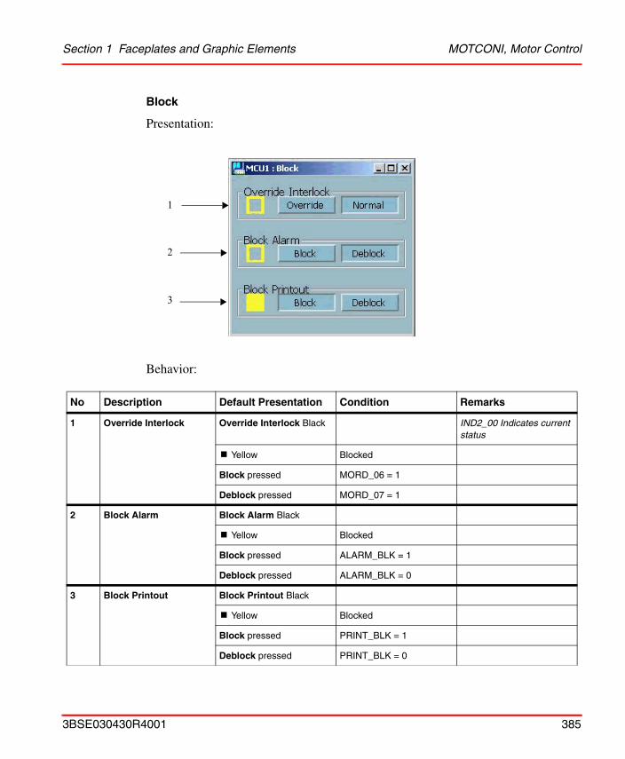
Section 1 Faceplates and Graphic Elements MOTCONI, Motor Control
Block
Presentation:
Behavior:
No Description Default Presentation Condition Remarks
1 Override Interlock Override Interlock Black IND2_00 Indicates current status
! Yellow Blocked
Block pressed MORD_06 = 1
Deblock pressed MORD_07 = 1
2 Block Alarm Block Alarm Black
! Yellow Blocked
Block pressed ALARM_BLK = 1
Deblock pressed ALARM_BLK = 0
3 Block Printout Block Printout Black
! Yellow Blocked
Block pressed PRINT_BLK = 1
Deblock pressed PRINT_BLK = 0
1
2
3
3BSE030430R4001 385
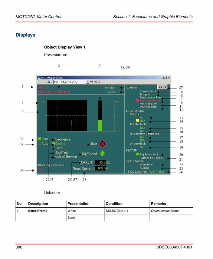
MOTCONI, Motor Control Section 1 Faceplates and Graphic Elements
Displays
Object Display View 1
Presentation:
Behavior
No Description Presentation Condition Remarks
1 SelectFrame White SELECTED = 1 Object select frame
Black -
1
2 5
25-2729-33
35
10
1314
15
17
19
20212223
89
1112
16
18
3
4
36
34
6
24
28
37
38, 39
386 3BSE030430R4001
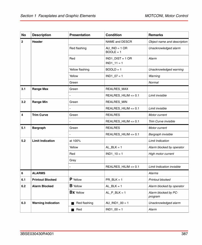
Section 1 Faceplates and Graphic Elements MOTCONI, Motor Control
2 Header NAME and DESCR Object name and description
Red flashing AU_IND = 1 ORBOOLE = 1
Unacknowledged alarm
Red IND1_DIST = 1 OR
IND1_11 = 1
Alarm
Yellow flashing BOOLD = 1 Unacknowledged warning
Yellow IND1_07 = 1 Warning
Green Normal
3.1 Range Max Green REALRES_MAX
- REALRES_HILIM <= 0.1 Limit invisible
3.2 Range Min Green REALRES_MIN
- REALRES_HILIM <= 0.1 Limit invisible
4 Trim Curve Green REALRES Motor current
- REALRES_HILIM <= 0.1 Trim Curve invisible
5.1 Bargraph Green REALRES Motor current
- REALRES_HILIM <= 0.1 Bargraph invisible
5.2 Limit Indication at 100% Limit Indication
Yellow AL_BLK = 1 Alarm blocked by operator
Red IND1_10 = 1 High motor current
Grey
- REALRES_HILIM <= 0.1 Limit Indication invisible
6 ALARMS Alarms
6.1 Printout Blocked P Yellow PR_BLK = 1 Printout blocked
6.2 Alarm Blocked B Yellow AL_BLK = 1 Alarm blocked by operator
Bx Yellow AL_P_BLK = 1 Alarm blocked by PC-program
6.3 Warning Indication Red flashing AU_IND1_00 = 1 Unacknowledged alarm
Red IND1_00 = 1 Alarm
No Description Presentation Condition Remarks
3BSE030430R4001 387
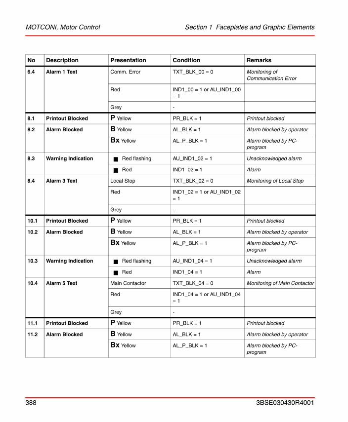
MOTCONI, Motor Control Section 1 Faceplates and Graphic Elements
6.4 Alarm 1 Text Comm. Error TXT_BLK_00 = 0 Monitoring of Communication Error
Red IND1_00 = 1 or AU_IND1_00 = 1
Grey -
8.1 Printout Blocked P Yellow PR_BLK = 1 Printout blocked
8.2 Alarm Blocked B Yellow AL_BLK = 1 Alarm blocked by operator
Bx Yellow AL_P_BLK = 1 Alarm blocked by PC-program
8.3 Warning Indication Red flashing AU_IND1_02 = 1 Unacknowledged alarm
Red IND1_02 = 1 Alarm
8.4 Alarm 3 Text Local Stop TXT_BLK_02 = 0 Monitoring of Local Stop
Red IND1_02 = 1 or AU_IND1_02 = 1
Grey -
10.1 Printout Blocked P Yellow PR_BLK = 1 Printout blocked
10.2 Alarm Blocked B Yellow AL_BLK = 1 Alarm blocked by operator
Bx Yellow AL_P_BLK = 1 Alarm blocked by PC-program
10.3 Warning Indication Red flashing AU_IND1_04 = 1 Unacknowledged alarm
Red IND1_04 = 1 Alarm
10.4 Alarm 5 Text Main Contactor TXT_BLK_04 = 0 Monitoring of Main Contactor
Red IND1_04 = 1 or AU_IND1_04 = 1
Grey -
11.1 Printout Blocked P Yellow PR_BLK = 1 Printout blocked
11.2 Alarm Blocked B Yellow AL_BLK = 1 Alarm blocked by operator
Bx Yellow AL_P_BLK = 1 Alarm blocked by PC-program
No Description Presentation Condition Remarks
388 3BSE030430R4001
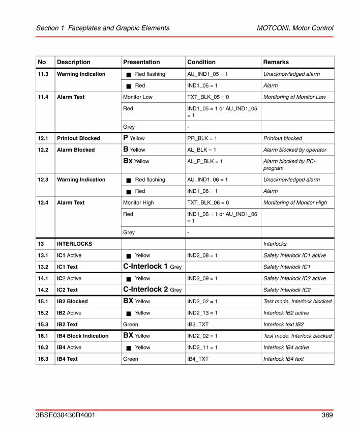
Section 1 Faceplates and Graphic Elements MOTCONI, Motor Control
11.3 Warning Indication Red flashing AU_IND1_05 = 1 Unacknowledged alarm
Red IND1_05 = 1 Alarm
11.4 Alarm Text Monitor Low TXT_BLK_05 = 0 Monitoring of Monitor Low
Red IND1_05 = 1 or AU_IND1_05 = 1
Grey -
12.1 Printout Blocked P Yellow PR_BLK = 1 Printout blocked
12.2 Alarm Blocked B Yellow AL_BLK = 1 Alarm blocked by operator
Bx Yellow AL_P_BLK = 1 Alarm blocked by PC-program
12.3 Warning Indication Red flashing AU_IND1_06 = 1 Unacknowledged alarm
Red IND1_06 = 1 Alarm
12.4 Alarm Text Monitor High TXT_BLK_06 = 0 Monitoring of Monitor High
Red IND1_06 = 1 or AU_IND1_06 = 1
Grey -
13 INTERLOCKS Interlocks
13.1 IC1 Active Yellow IND2_08 = 1 Safety Interlock IC1 active
13.2 IC1 Text C-Interlock 1 Grey Safety Interlock IC1
14.1 IC2 Active Yellow IND2_09 = 1 Safety Interlock IC2 active
14.2 IC2 Text C-Interlock 2 Grey Safety Interlock IC2
15.1 IB2 Blocked BX Yellow IND2_02 = 1 Test mode. Interlock blocked
15.2 IB2 Active Yellow IND2_13 = 1 Interlock IB2 active
15.3 IB2 Text Green IB2_TXT Interlock text IB2
16.1 IB4 Block Indication BX Yellow IND2_02 = 1 Test mode. Interlock blocked
16.2 IB4 Active Yellow IND2_11 = 1 Interlock IB4 active
16.3 IB4 Text Green IB4_TXT Interlock IB4 text
No Description Presentation Condition Remarks
3BSE030430R4001 389
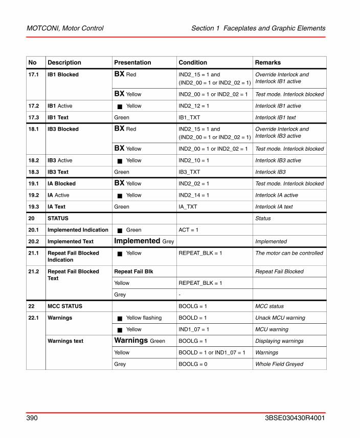
MOTCONI, Motor Control Section 1 Faceplates and Graphic Elements
17.1 IB1 Blocked BX Red IND2_15 = 1 and
(IND2_00 = 1 or IND2_02 = 1)
Override Interlock and Interlock IB1 active
BX Yellow IND2_00 = 1 or IND2_02 = 1 Test mode. Interlock blocked
17.2 IB1 Active Yellow IND2_12 = 1 Interlock IB1 active
17.3 IB1 Text Green IB1_TXT Interlock IB1 text
18.1 IB3 Blocked BX Red IND2_15 = 1 and
(IND2_00 = 1 or IND2_02 = 1)
Override Interlock and Interlock IB3 active
BX Yellow IND2_00 = 1 or IND2_02 = 1 Test mode. Interlock blocked
18.2 IB3 Active Yellow IND2_10 = 1 Interlock IB3 active
18.3 IB3 Text Green IB3_TXT Interlock IB3
19.1 IA Blocked BX Yellow IND2_02 = 1 Test mode. Interlock blocked
19.2 IA Active Yellow IND2_14 = 1 Interlock IA active
19.3 IA Text Green IA_TXT Interlock IA text
20 STATUS Status
20.1 Implemented Indication Green ACT = 1
20.2 Implemented Text Implemented Grey Implemented
21.1 Repeat Fail Blocked Indication
Yellow REPEAT_BLK = 1 The motor can be controlled
21.2 Repeat Fail Blocked Text
Repeat Fail Blk Repeat Fail Blocked
Yellow REPEAT_BLK = 1
Grey -
22 MCC STATUS BOOLG = 1 MCC status
22.1 Warnings Yellow flashing BOOLD = 1 Unack MCU warning
Yellow IND1_07 = 1 MCU warning
Warnings text Warnings Green BOOLG = 1 Displaying warnings
Yellow BOOLD = 1 or IND1_07 = 1 Warnings
Grey BOOLG = 0 Whole Field Greyed
No Description Presentation Condition Remarks
390 3BSE030430R4001
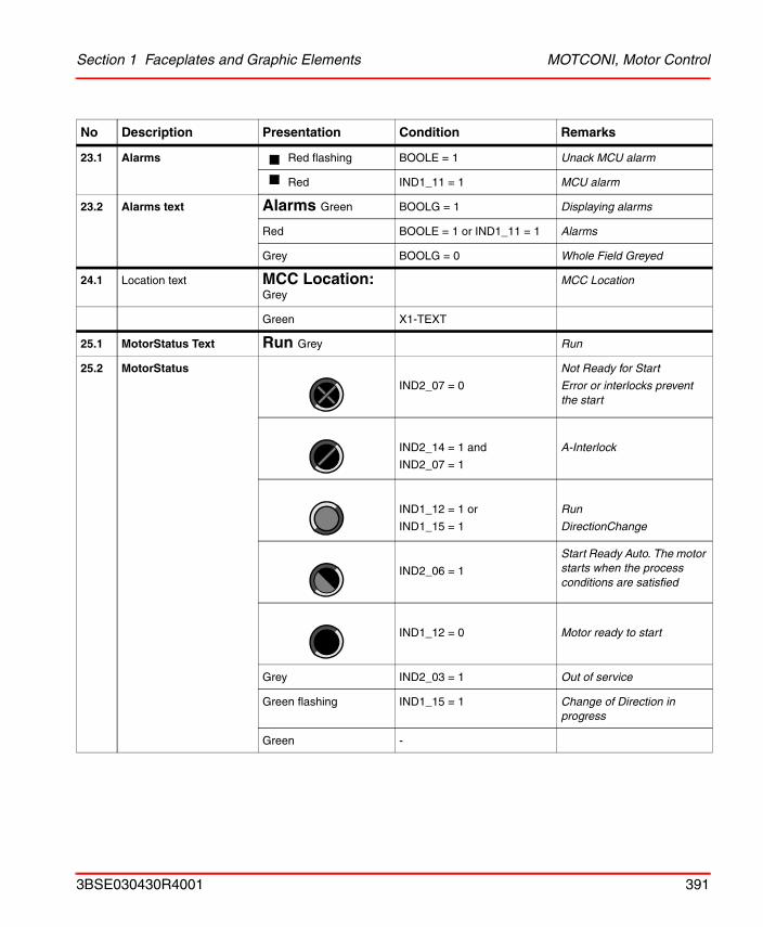
Section 1 Faceplates and Graphic Elements MOTCONI, Motor Control
23.1 Alarms Red flashing BOOLE = 1 Unack MCU alarm
Red IND1_11 = 1 MCU alarm
23.2 Alarms text Alarms Green BOOLG = 1 Displaying alarms
Red BOOLE = 1 or IND1_11 = 1 Alarms
Grey BOOLG = 0 Whole Field Greyed
24.1 Location text MCC Location: Grey
MCC Location
Green X1-TEXT
25.1 MotorStatus Text Run Grey Run
25.2 MotorStatus
IND2_07 = 0
Not Ready for Start
Error or interlocks prevent the start
IND2_14 = 1 and
IND2_07 = 1
A-Interlock
IND1_12 = 1 or
IND1_15 = 1
Run
DirectionChange
IND2_06 = 1
Start Ready Auto. The motor starts when the process conditions are satisfied
IND1_12 = 0 Motor ready to start
Grey IND2_03 = 1 Out of service
Green flashing IND1_15 = 1 Change of Direction in progress
Green -
No Description Presentation Condition Remarks
3BSE030430R4001 391
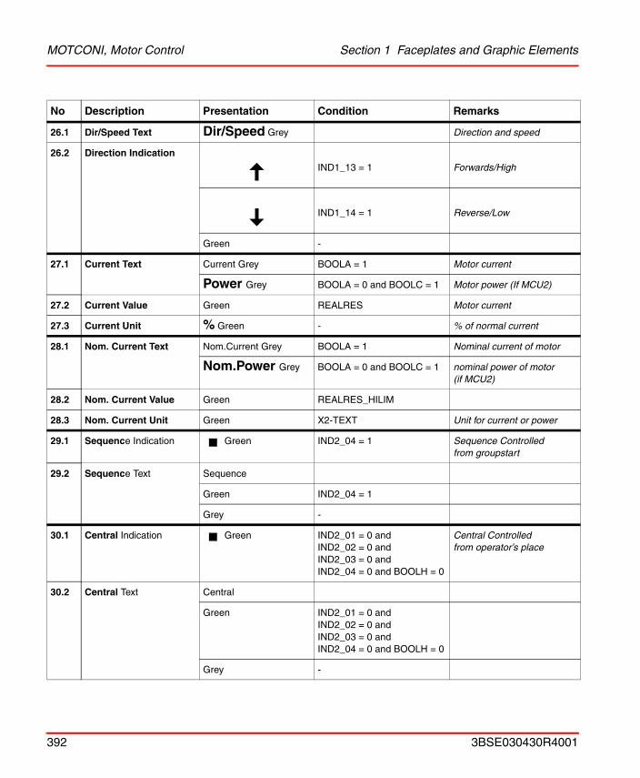
MOTCONI, Motor Control Section 1 Faceplates and Graphic Elements
26.1 Dir/Speed Text Dir/Speed Grey Direction and speed
26.2 Direction Indication
IND1_13 = 1 Forwards/High
IND1_14 = 1 Reverse/Low
Green -
27.1 Current Text Current Grey BOOLA = 1 Motor current
Power Grey BOOLA = 0 and BOOLC = 1 Motor power (If MCU2)
27.2 Current Value Green REALRES Motor current
27.3 Current Unit % Green - % of normal current
28.1 Nom. Current Text Nom.Current Grey BOOLA = 1 Nominal current of motor
Nom.Power Grey BOOLA = 0 and BOOLC = 1 nominal power of motor(if MCU2)
28.2 Nom. Current Value Green REALRES_HILIM
28.3 Nom. Current Unit Green X2-TEXT Unit for current or power
29.1 Sequence Indication Green IND2_04 = 1 Sequence Controlled from groupstart
29.2 Sequence Text Sequence
Green IND2_04 = 1
Grey -
30.1 Central Indication Green IND2_01 = 0 andIND2_02 = 0 andIND2_03 = 0 andIND2_04 = 0 and BOOLH = 0
Central Controlled from operator’s place
30.2 Central Text Central
Green IND2_01 = 0 andIND2_02 = 0 andIND2_03 = 0 andIND2_04 = 0 and BOOLH = 0
Grey -
No Description Presentation Condition Remarks
392 3BSE030430R4001
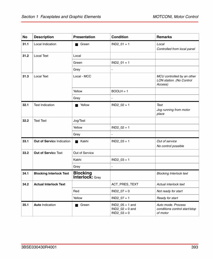
Section 1 Faceplates and Graphic Elements MOTCONI, Motor Control
31.1 Local Indication Green IND2_01 = 1 Local
Controlled from local panel
31.2 Local Text Local
Green IND2_01 = 1
Grey -
31.3 Local Text Local - MCC MCU controlled by an other LON station. (No Control Access)
Yellow BOOLH = 1
Grey -
32.1 Test Indication Yellow IND2_02 = 1 Test
Jog running from motor place
32.2 Test Text Jog/Test
Yellow IND2_02 = 1
Grey -
33.1 Out of Service Indication Kakhi IND2_03 = 1 Out of service
No control possible
33.2 Out of Service Text Out of Service
Kakhi IND2_03 = 1
Grey -
34.1 Blocking Interlock Text Blocking Interlock: Grey
Blocking Interlock text
34.2 Actual Interlock Text ACT_PRES_TEXT Actual interlock text
Red IND2_07 = 0 Not ready for start
Yellow IND2_07 = 1 Ready for start
35.1 Auto Indication Green IND2_05 = 1 andIND2_02 = 0 andIND2_03 = 0
Auto mode. Process conditions control start/stop of motor
No Description Presentation Condition Remarks
3BSE030430R4001 393
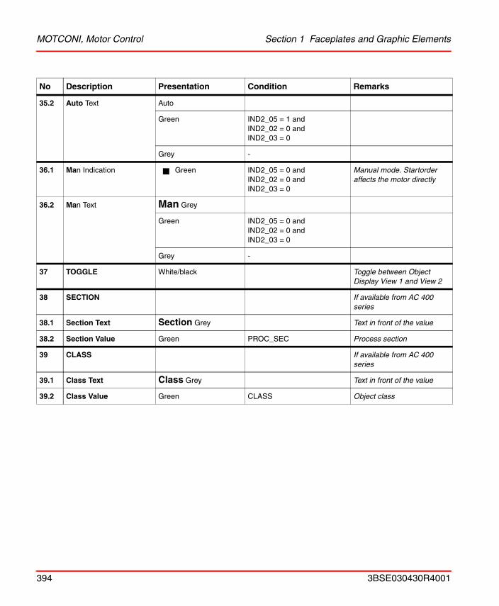
MOTCONI, Motor Control Section 1 Faceplates and Graphic Elements
35.2 Auto Text Auto
Green IND2_05 = 1 andIND2_02 = 0 andIND2_03 = 0
Grey -
36.1 Man Indication Green IND2_05 = 0 andIND2_02 = 0 andIND2_03 = 0
Manual mode. Startorder affects the motor directly
36.2 Man Text Man Grey
Green IND2_05 = 0 andIND2_02 = 0 andIND2_03 = 0
Grey -
37 TOGGLE White/black Toggle between Object Display View 1 and View 2
38 SECTION If available from AC 400 series
38.1 Section Text Section Grey Text in front of the value
38.2 Section Value Green PROC_SEC Process section
39 CLASS If available from AC 400 series
39.1 Class Text Class Grey Text in front of the value
39.2 Class Value Green CLASS Object class
No Description Presentation Condition Remarks
394 3BSE030430R4001
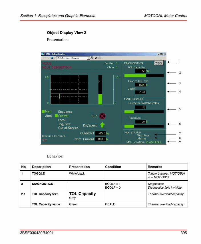
Section 1 Faceplates and Graphic Elements MOTCONI, Motor Control
Object Display View 2
Presentation:
Behavior:
No Description Presentation Condition Remarks
1 TOGGLE White/black Toggle between MOTIOB01 and MOTIOB02
2 DIAGNOSTICS BOOLF = 1BOOLF = 0
DiagnosticsDiagnostics field invisible
2.1 TOL Capacity text TOL Capacity Grey
Thermal overload capacity
TOL Capacity value Green REALE Thermal overload capacity
9
1
2
78
6
4
5
3
3BSE030430R4001 395
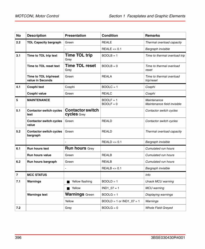
MOTCONI, Motor Control Section 1 Faceplates and Graphic Elements
2.2 TOL Capacity bargraph Green REALE Thermal overload capacity
- REALE <= 0.1 Bargraph invisible
3.1 Time to TOL trip text Time TOL trip Grey
BOOLB = 1 Time to thermal overload trip
Time to TOL reset text Time TOL reset Grey
BOOLB = 0 Time to thermal overload reset
Time to TOL trip/reset value in Seconds
Green REALA Time to thermal overload trip/reset
4.1 Cosphi text Cosphi BOOLC = 1 Cosphi
Cosphi value Green REALC Cosphi
5 MAINTENANCE BOOLF = 1BOOLF = 0
MaintenanceMaintenance field invisible
5.1 Contactor switch cycles text
Contactor switch cycles Grey
Contactor switch cycles
Contactor switch cycles value
Green REALD Contactor switch cycles
5.2 Contactor switch cycles bargraph
Green REALD Thermal overload capacity
- REALD <= 0.1 Bargraph invisible
6.1 Run hours text Run hours Grey Cumulated run hours
Run hours value Green REALB Cumulated run hours
6.2 Run hours bargraph Green REALB Cumulated run hours
- REALB <= 0.1 Bargraph invisible
7 MCC STATUS Info
7.1 Warnings Yellow flashing BOOLD = 1 Unack MCU warning
Yellow IND1_07 = 1 MCU warning
Warnings text Warnings Green BOOLG = 1 Displaying warnings
Yellow BOOLD = 1 or IND1_07 = 1 Warnings
7.2 Grey BOOLG = 0 Whole Field Greyed
No Description Presentation Condition Remarks
396 3BSE030430R4001
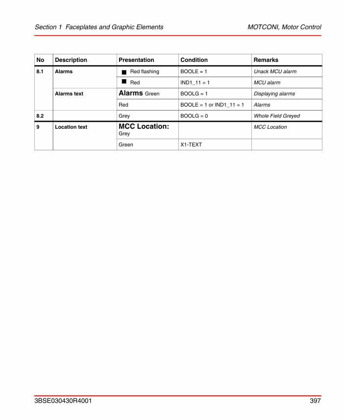
Section 1 Faceplates and Graphic Elements MOTCONI, Motor Control
8.1 Alarms Red flashing BOOLE = 1 Unack MCU alarm
Red IND1_11 = 1 MCU alarm
Alarms text Alarms Green BOOLG = 1 Displaying alarms
Red BOOLE = 1 or IND1_11 = 1 Alarms
8.2 Grey BOOLG = 0 Whole Field Greyed
9 Location text MCC Location: Grey
MCC Location
Green X1-TEXT
No Description Presentation Condition Remarks
3BSE030430R4001 397
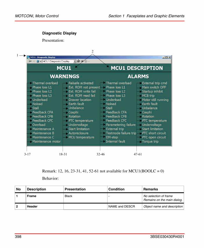
MOTCONI, Motor Control Section 1 Faceplates and Graphic Elements
Diagnostic Display
Presentation:
Remark: 12, 16, 23-31, 41, 52-61 not available for MCU1(BOOLC = 0)
Behavior:
No Description Presentation Condition Remarks
1 Frame Black - No selection of frameRemains on the main dialog.
2 Header NAME and DESCR Object name and description
12
3-17 18-31 32-46 47-61
398 3BSE030430R4001
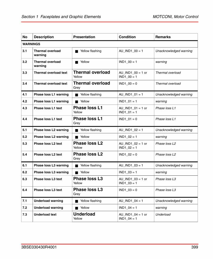
Section 1 Faceplates and Graphic Elements MOTCONI, Motor Control
WARNINGS
3.1 Thermal overload warning
Yellow flashing AU_IND1_00 = 1 Unacknowledged warning
3.2 Thermal overload warning
Yellow IND1_00 = 1 warning
3.3 Thermal overload text Thermal overloadYellow
AU_IND1_00 = 1 orIND1_00 = 1
Thermal overload
3.4 Thermal overload text Thermal overloadGrey
IND1_00 = 0 Thermal overload
4.1 Phase loss L1 warning Yellow flashing AU_IND1_01 = 1 Unacknowledged warning
4.2 Phase loss L1 warning Yellow IND1_01 = 1 warning
4.3 Phase loss L1 text Phase loss L1Yellow
AU_IND1_01 = 1 orIND1_01 = 1
Phase loss L1
4.4 Phase loss L1 text Phase loss L1Grey
IND1_01 = 0 Phase loss L1
5.1 Phase loss L2 warning Yellow flashing AU_IND1_02 = 1 Unacknowledged warning
5.2 Phase loss L2 warning Yellow IND1_02 = 1 warning
5.3 Phase loss L2 text Phase loss L2Yellow
AU_IND1_02 = 1 orIND1_02 = 1
Phase loss L2
5.4 Phase loss L2 text Phase loss L2Grey
IND1_02 = 0 Phase loss L2
6.1 Phase loss L3 warning Yellow flashing AU_IND1_03 = 1 Unacknowledged warning
6.2 Phase loss L3 warning Yellow IND1_03 = 1 warning
6.3 Phase loss L3 text Phase loss L3Yellow
AU_IND1_03 = 1 orIND1_03 = 1
Phase loss L3
6.4 Phase loss L3 text Phase loss L3Grey
IND1_03 = 0 Phase loss L3
7.1 Underload warning Yellow flashing AU_IND1_04 = 1 Unacknowledged warning
7.2 Underload warning Yellow IND1_04 = 1 warning
7.3 Underload text UnderloadYellow
AU_IND1_04 = 1 orIND1_04 = 1
Underload
No Description Presentation Condition Remarks
3BSE030430R4001 399
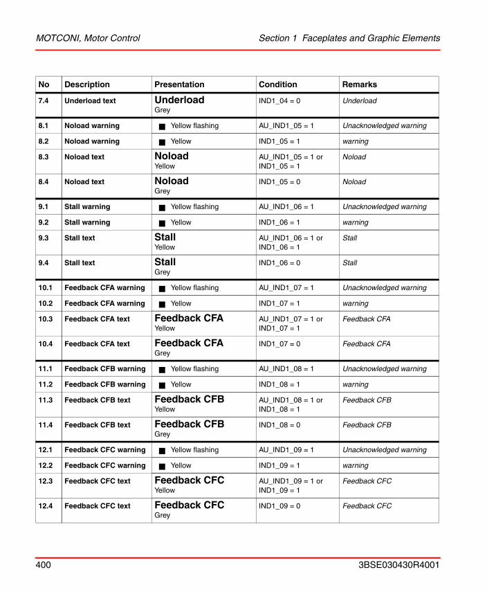
MOTCONI, Motor Control Section 1 Faceplates and Graphic Elements
7.4 Underload text UnderloadGrey
IND1_04 = 0 Underload
8.1 Noload warning Yellow flashing AU_IND1_05 = 1 Unacknowledged warning
8.2 Noload warning Yellow IND1_05 = 1 warning
8.3 Noload text NoloadYellow
AU_IND1_05 = 1 orIND1_05 = 1
Noload
8.4 Noload text NoloadGrey
IND1_05 = 0 Noload
9.1 Stall warning Yellow flashing AU_IND1_06 = 1 Unacknowledged warning
9.2 Stall warning Yellow IND1_06 = 1 warning
9.3 Stall text StallYellow
AU_IND1_06 = 1 orIND1_06 = 1
Stall
9.4 Stall text StallGrey
IND1_06 = 0 Stall
10.1 Feedback CFA warning Yellow flashing AU_IND1_07 = 1 Unacknowledged warning
10.2 Feedback CFA warning Yellow IND1_07 = 1 warning
10.3 Feedback CFA text Feedback CFAYellow
AU_IND1_07 = 1 orIND1_07 = 1
Feedback CFA
10.4 Feedback CFA text Feedback CFAGrey
IND1_07 = 0 Feedback CFA
11.1 Feedback CFB warning Yellow flashing AU_IND1_08 = 1 Unacknowledged warning
11.2 Feedback CFB warning Yellow IND1_08 = 1 warning
11.3 Feedback CFB text Feedback CFBYellow
AU_IND1_08 = 1 orIND1_08 = 1
Feedback CFB
11.4 Feedback CFB text Feedback CFBGrey
IND1_08 = 0 Feedback CFB
12.1 Feedback CFC warning Yellow flashing AU_IND1_09 = 1 Unacknowledged warning
12.2 Feedback CFC warning Yellow IND1_09 = 1 warning
12.3 Feedback CFC text Feedback CFCYellow
AU_IND1_09 = 1 orIND1_09 = 1
Feedback CFC
12.4 Feedback CFC text Feedback CFCGrey
IND1_09 = 0 Feedback CFC
No Description Presentation Condition Remarks
400 3BSE030430R4001
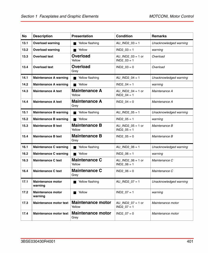
Section 1 Faceplates and Graphic Elements MOTCONI, Motor Control
13.1 Overload warning Yellow flashing AU_IND2_03 = 1 Unacknowledged warning
13.2 Overload warning Yellow IND2_03 = 1 warning
13.3 Overload text OverloadYellow
AU_IND2_03 = 1 orIND2_03 = 1
Overload
13.4 Overload text OverloadGrey
IND2_03 = 0 Overload
14.1 Maintenance A warning Yellow flashing AU_IND2_04 = 1 Unacknowledged warning
14.2 Maintenance A warning Yellow IND2_04 = 1 warning
14.3 Maintenance A text Maintenance AYellow
AU_IND2_04 = 1 orIND2_04 = 1
Maintenance A
14.4 Maintenance A text Maintenance AGrey
IND2_04 = 0 Maintenance A
15.1 Maintenance B warning Yellow flashing AU_IND2_05 = 1 Unacknowledged warning
15.2 Maintenance B warning Yellow IND2_05 = 1 warning
15.3 Maintenance B text Maintenance BYellow
AU_IND2_05 = 1 orIND2_05 = 1
Maintenance B
15.4 Maintenance B text Maintenance BGrey
IND2_05 = 0 Maintenance B
16.1 Maintenance C warning Yellow flashing AU_IND2_06 = 1 Unacknowledged warning
16.2 Maintenance C warning Yellow IND2_06 = 1 warning
16.3 Maintenance C text Maintenance CYellow
AU_IND2_06 = 1 orIND2_06 = 1
Maintenance C
16.4 Maintenance C text Maintenance CGrey
IND2_06 = 0 Maintenance C
17.1 Maintenance motor warning
Yellow flashing AU_IND2_07 = 1 Unacknowledged warning
17.2 Maintenance motor warning
Yellow IND2_07 = 1 warning
17.3 Maintenance motor text Maintenance motorYellow
AU_IND2_07 = 1 orIND2_07 = 1
Maintenance motor
17.4 Maintenance motor text Maintenance motorGrey
IND2_07 = 0 Maintenance motor
No Description Presentation Condition Remarks
3BSE030430R4001 401
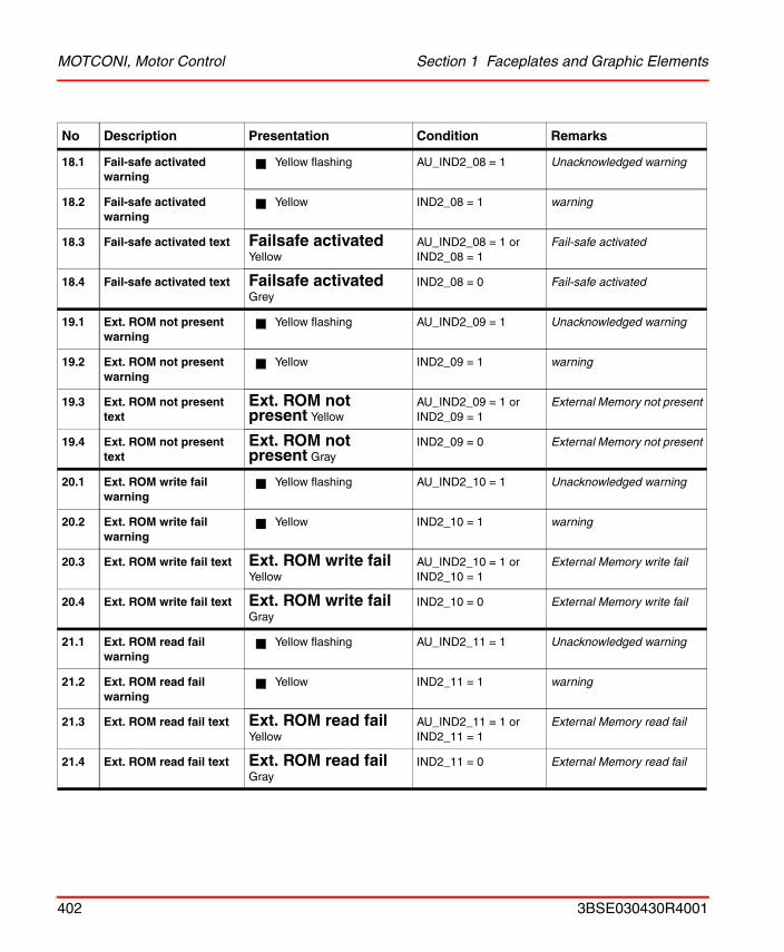
MOTCONI, Motor Control Section 1 Faceplates and Graphic Elements
18.1 Fail-safe activated warning
Yellow flashing AU_IND2_08 = 1 Unacknowledged warning
18.2 Fail-safe activated warning
Yellow IND2_08 = 1 warning
18.3 Fail-safe activated text Failsafe activatedYellow
AU_IND2_08 = 1 orIND2_08 = 1
Fail-safe activated
18.4 Fail-safe activated text Failsafe activatedGrey
IND2_08 = 0 Fail-safe activated
19.1 Ext. ROM not present warning
Yellow flashing AU_IND2_09 = 1 Unacknowledged warning
19.2 Ext. ROM not present warning
Yellow IND2_09 = 1 warning
19.3 Ext. ROM not present text
Ext. ROM not present Yellow
AU_IND2_09 = 1 orIND2_09 = 1
External Memory not present
19.4 Ext. ROM not present text
Ext. ROM not present Gray
IND2_09 = 0 External Memory not present
20.1 Ext. ROM write fail warning
Yellow flashing AU_IND2_10 = 1 Unacknowledged warning
20.2 Ext. ROM write fail warning
Yellow IND2_10 = 1 warning
20.3 Ext. ROM write fail text Ext. ROM write fail Yellow
AU_IND2_10 = 1 orIND2_10 = 1
External Memory write fail
20.4 Ext. ROM write fail text Ext. ROM write fail Gray
IND2_10 = 0 External Memory write fail
21.1 Ext. ROM read fail warning
Yellow flashing AU_IND2_11 = 1 Unacknowledged warning
21.2 Ext. ROM read fail warning
Yellow IND2_11 = 1 warning
21.3 Ext. ROM read fail text Ext. ROM read fail Yellow
AU_IND2_11 = 1 orIND2_11 = 1
External Memory read fail
21.4 Ext. ROM read fail text Ext. ROM read fail Gray
IND2_11 = 0 External Memory read fail
No Description Presentation Condition Remarks
402 3BSE030430R4001
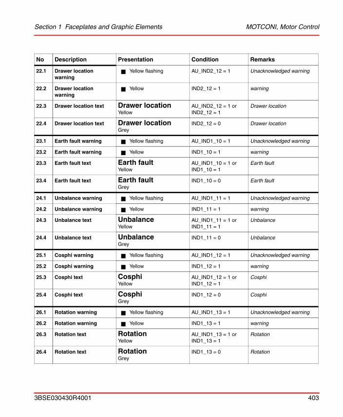
Section 1 Faceplates and Graphic Elements MOTCONI, Motor Control
22.1 Drawer location warning
Yellow flashing AU_IND2_12 = 1 Unacknowledged warning
22.2 Drawer location warning
Yellow IND2_12 = 1 warning
22.3 Drawer location text Drawer locationYellow
AU_IND2_12 = 1 orIND2_12 = 1
Drawer location
22.4 Drawer location text Drawer locationGrey
IND2_12 = 0 Drawer location
23.1 Earth fault warning Yellow flashing AU_IND1_10 = 1 Unacknowledged warning
23.2 Earth fault warning Yellow IND1_10 = 1 warning
23.3 Earth fault text Earth faultYellow
AU_IND1_10 = 1 orIND1_10 = 1
Earth fault
23.4 Earth fault text Earth faultGrey
IND1_10 = 0 Earth fault
24.1 Unbalance warning Yellow flashing AU_IND1_11 = 1 Unacknowledged warning
24.2 Unbalance warning Yellow IND1_11 = 1 warning
24.3 Unbalance text UnbalanceYellow
AU_IND1_11 = 1 orIND1_11 = 1
Unbalance
24.4 Unbalance text UnbalanceGrey
IND1_11 = 0 Unbalance
25.1 Cosphi warning Yellow flashing AU_IND1_12 = 1 Unacknowledged warning
25.2 Cosphi warning Yellow IND1_12 = 1 warning
25.3 Cosphi text CosphiYellow
AU_IND1_12 = 1 orIND1_12 = 1
Cosphi
25.4 Cosphi text CosphiGrey
IND1_12 = 0 Cosphi
26.1 Rotation warning Yellow flashing AU_IND1_13 = 1 Unacknowledged warning
26.2 Rotation warning Yellow IND1_13 = 1 warning
26.3 Rotation text RotationYellow
AU_IND1_13 = 1 orIND1_13 = 1
Rotation
26.4 Rotation text RotationGrey
IND1_13 = 0 Rotation
No Description Presentation Condition Remarks
3BSE030430R4001 403
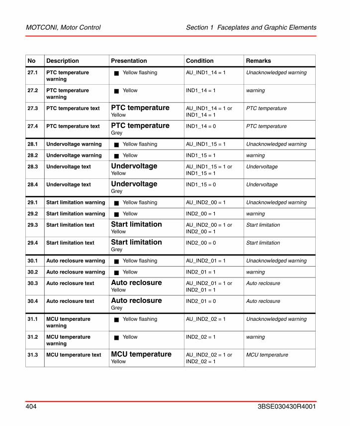
MOTCONI, Motor Control Section 1 Faceplates and Graphic Elements
27.1 PTC temperature warning
Yellow flashing AU_IND1_14 = 1 Unacknowledged warning
27.2 PTC temperature warning
Yellow IND1_14 = 1 warning
27.3 PTC temperature text PTC temperatureYellow
AU_IND1_14 = 1 orIND1_14 = 1
PTC temperature
27.4 PTC temperature text PTC temperatureGrey
IND1_14 = 0 PTC temperature
28.1 Undervoltage warning Yellow flashing AU_IND1_15 = 1 Unacknowledged warning
28.2 Undervoltage warning Yellow IND1_15 = 1 warning
28.3 Undervoltage text UndervoltageYellow
AU_IND1_15 = 1 orIND1_15 = 1
Undervoltage
28.4 Undervoltage text UndervoltageGrey
IND1_15 = 0 Undervoltage
29.1 Start limitation warning Yellow flashing AU_IND2_00 = 1 Unacknowledged warning
29.2 Start limitation warning Yellow IND2_00 = 1 warning
29.3 Start limitation text Start limitationYellow
AU_IND2_00 = 1 orIND2_00 = 1
Start limitation
29.4 Start limitation text Start limitationGrey
IND2_00 = 0 Start limitation
30.1 Auto reclosure warning Yellow flashing AU_IND2_01 = 1 Unacknowledged warning
30.2 Auto reclosure warning Yellow IND2_01 = 1 warning
30.3 Auto reclosure text Auto reclosureYellow
AU_IND2_01 = 1 orIND2_01 = 1
Auto reclosure
30.4 Auto reclosure text Auto reclosureGrey
IND2_01 = 0 Auto reclosure
31.1 MCU temperature warning
Yellow flashing AU_IND2_02 = 1 Unacknowledged warning
31.2 MCU temperature warning
Yellow IND2_02 = 1 warning
31.3 MCU temperature text MCU temperatureYellow
AU_IND2_02 = 1 orIND2_02 = 1
MCU temperature
No Description Presentation Condition Remarks
404 3BSE030430R4001
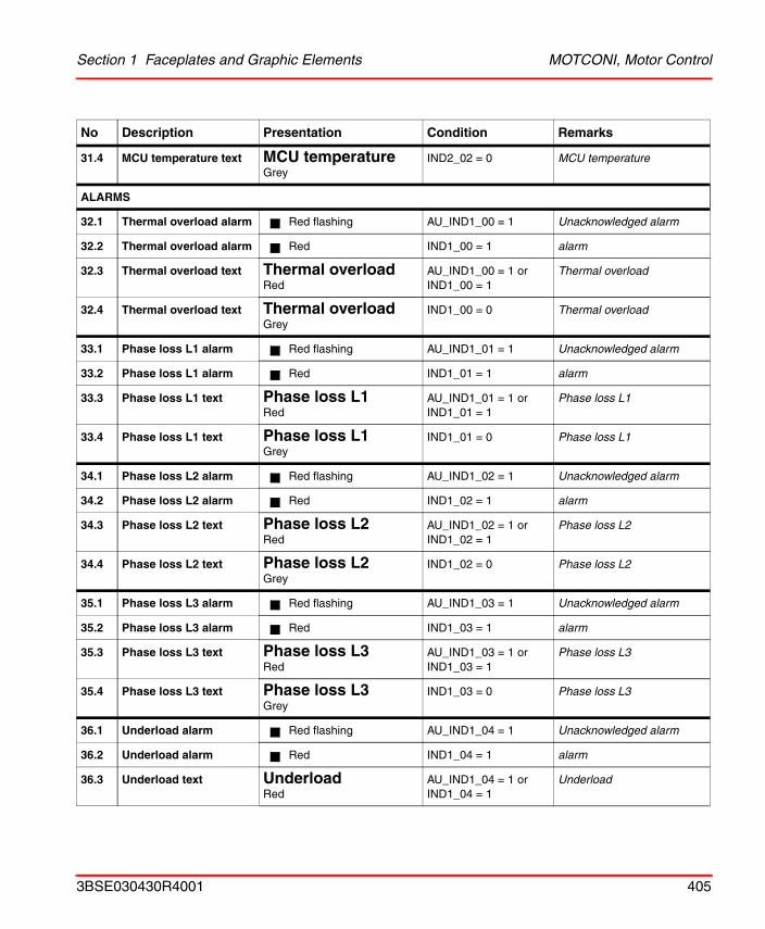
Section 1 Faceplates and Graphic Elements MOTCONI, Motor Control
31.4 MCU temperature text MCU temperatureGrey
IND2_02 = 0 MCU temperature
ALARMS
32.1 Thermal overload alarm Red flashing AU_IND1_00 = 1 Unacknowledged alarm
32.2 Thermal overload alarm Red IND1_00 = 1 alarm
32.3 Thermal overload text Thermal overloadRed
AU_IND1_00 = 1 orIND1_00 = 1
Thermal overload
32.4 Thermal overload text Thermal overloadGrey
IND1_00 = 0 Thermal overload
33.1 Phase loss L1 alarm Red flashing AU_IND1_01 = 1 Unacknowledged alarm
33.2 Phase loss L1 alarm Red IND1_01 = 1 alarm
33.3 Phase loss L1 text Phase loss L1Red
AU_IND1_01 = 1 orIND1_01 = 1
Phase loss L1
33.4 Phase loss L1 text Phase loss L1Grey
IND1_01 = 0 Phase loss L1
34.1 Phase loss L2 alarm Red flashing AU_IND1_02 = 1 Unacknowledged alarm
34.2 Phase loss L2 alarm Red IND1_02 = 1 alarm
34.3 Phase loss L2 text Phase loss L2Red
AU_IND1_02 = 1 orIND1_02 = 1
Phase loss L2
34.4 Phase loss L2 text Phase loss L2Grey
IND1_02 = 0 Phase loss L2
35.1 Phase loss L3 alarm Red flashing AU_IND1_03 = 1 Unacknowledged alarm
35.2 Phase loss L3 alarm Red IND1_03 = 1 alarm
35.3 Phase loss L3 text Phase loss L3Red
AU_IND1_03 = 1 orIND1_03 = 1
Phase loss L3
35.4 Phase loss L3 text Phase loss L3Grey
IND1_03 = 0 Phase loss L3
36.1 Underload alarm Red flashing AU_IND1_04 = 1 Unacknowledged alarm
36.2 Underload alarm Red IND1_04 = 1 alarm
36.3 Underload text UnderloadRed
AU_IND1_04 = 1 orIND1_04 = 1
Underload
No Description Presentation Condition Remarks
3BSE030430R4001 405
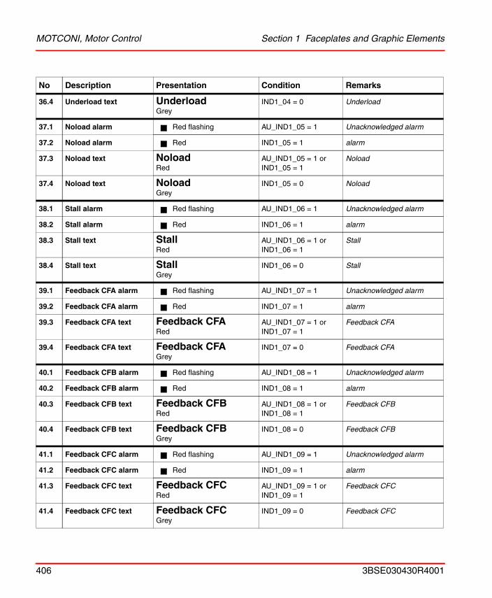
MOTCONI, Motor Control Section 1 Faceplates and Graphic Elements
36.4 Underload text UnderloadGrey
IND1_04 = 0 Underload
37.1 Noload alarm Red flashing AU_IND1_05 = 1 Unacknowledged alarm
37.2 Noload alarm Red IND1_05 = 1 alarm
37.3 Noload text NoloadRed
AU_IND1_05 = 1 orIND1_05 = 1
Noload
37.4 Noload text NoloadGrey
IND1_05 = 0 Noload
38.1 Stall alarm Red flashing AU_IND1_06 = 1 Unacknowledged alarm
38.2 Stall alarm Red IND1_06 = 1 alarm
38.3 Stall text StallRed
AU_IND1_06 = 1 orIND1_06 = 1
Stall
38.4 Stall text StallGrey
IND1_06 = 0 Stall
39.1 Feedback CFA alarm Red flashing AU_IND1_07 = 1 Unacknowledged alarm
39.2 Feedback CFA alarm Red IND1_07 = 1 alarm
39.3 Feedback CFA text Feedback CFARed
AU_IND1_07 = 1 orIND1_07 = 1
Feedback CFA
39.4 Feedback CFA text Feedback CFAGrey
IND1_07 = 0 Feedback CFA
40.1 Feedback CFB alarm Red flashing AU_IND1_08 = 1 Unacknowledged alarm
40.2 Feedback CFB alarm Red IND1_08 = 1 alarm
40.3 Feedback CFB text Feedback CFBRed
AU_IND1_08 = 1 orIND1_08 = 1
Feedback CFB
40.4 Feedback CFB text Feedback CFBGrey
IND1_08 = 0 Feedback CFB
41.1 Feedback CFC alarm Red flashing AU_IND1_09 = 1 Unacknowledged alarm
41.2 Feedback CFC alarm Red IND1_09 = 1 alarm
41.3 Feedback CFC text Feedback CFCRed
AU_IND1_09 = 1 orIND1_09 = 1
Feedback CFC
41.4 Feedback CFC text Feedback CFCGrey
IND1_09 = 0 Feedback CFC
No Description Presentation Condition Remarks
406 3BSE030430R4001
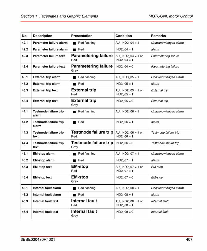
Section 1 Faceplates and Graphic Elements MOTCONI, Motor Control
42.1 Parameter failure alarm Red flashing AU_IND2_04 = 1 Unacknowledged alarm
42.2 Parameter failure alarm Red IND2_04 = 1 alarm
42.3 Parameter failure text Parametering failureRed
AU_IND2_04 = 1 orIND2_04 = 1
Parametering failure
42.4 Parameter failure text Parametering failureGrey
IND2_04 = 0 Parametering failure
43.1 External trip alarm Red flashing AU_IND3_05 = 1 Unacknowledged alarm
43.2 External trip alarm Red IND3_05 = 1 alarm
43.3 External trip text External tripRed
AU_IND2_05 = 1 orIND2_05 = 1
External trip
43.4 External trip text External tripGrey
IND2_05 = 0 External trip
44.1 Testmode failure trip alarm
Red flashing AU_IND2_06 = 1 Unacknowledged alarm
44.2 Testmode failure trip alarm
Red IND2_06 = 1 alarm
44.3 Testmode failure trip text
Testmode failure tripRed
AU_IND2_06 = 1 orIND2_06 = 1
Testmode failure trip
44.4 Testmode failure trip text
Testmode failure tripGrey
IND2_06 = 0 Testmode failure trip
45.1 EM-stop alarm Red flashing AU_IND2_07 = 1 Unacknowledged alarm
45.2 EM-stop alarm Red IND2_07 = 1 alarm
45.3 EM-stop text EM-stopRed
AU_IND2_07 = 1 orIND2_07 = 1
EM-stop
45.4 EM-stop text EM-stopGrey
IND2_07 = 0 EM-stop
46.1 Internal fault alarm Red flashing AU_IND2_08 = 1 Unacknowledged alarm
46.2 Internal fault alarm Red IND2_08 = 1 alarm
46.3 Internal fault text Internal faultRed
AU_IND2_08 = 1 orIND2_08 = 1
Internal fault
46.4 Internal fault text Internal faultGrey
IND2_08 = 0 Internal fault
No Description Presentation Condition Remarks
3BSE030430R4001 407
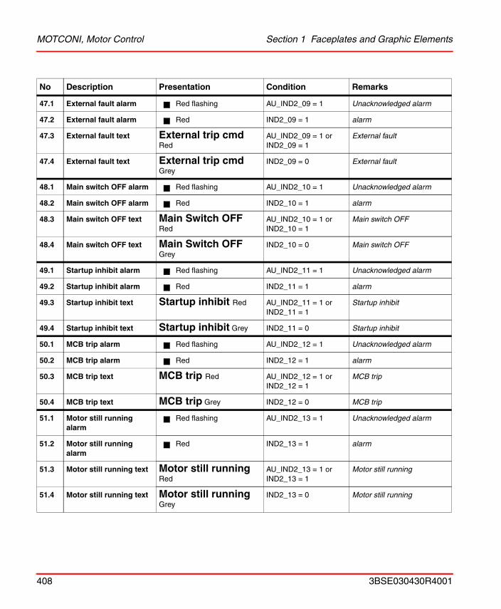
MOTCONI, Motor Control Section 1 Faceplates and Graphic Elements
47.1 External fault alarm Red flashing AU_IND2_09 = 1 Unacknowledged alarm
47.2 External fault alarm Red IND2_09 = 1 alarm
47.3 External fault text External trip cmdRed
AU_IND2_09 = 1 orIND2_09 = 1
External fault
47.4 External fault text External trip cmdGrey
IND2_09 = 0 External fault
48.1 Main switch OFF alarm Red flashing AU_IND2_10 = 1 Unacknowledged alarm
48.2 Main switch OFF alarm Red IND2_10 = 1 alarm
48.3 Main switch OFF text Main Switch OFFRed
AU_IND2_10 = 1 orIND2_10 = 1
Main switch OFF
48.4 Main switch OFF text Main Switch OFFGrey
IND2_10 = 0 Main switch OFF
49.1 Startup inhibit alarm Red flashing AU_IND2_11 = 1 Unacknowledged alarm
49.2 Startup inhibit alarm Red IND2_11 = 1 alarm
49.3 Startup inhibit text Startup inhibit Red AU_IND2_11 = 1 orIND2_11 = 1
Startup inhibit
49.4 Startup inhibit text Startup inhibit Grey IND2_11 = 0 Startup inhibit
50.1 MCB trip alarm Red flashing AU_IND2_12 = 1 Unacknowledged alarm
50.2 MCB trip alarm Red IND2_12 = 1 alarm
50.3 MCB trip text MCB trip Red AU_IND2_12 = 1 orIND2_12 = 1
MCB trip
50.4 MCB trip text MCB trip Grey IND2_12 = 0 MCB trip
51.1 Motor still running alarm
Red flashing AU_IND2_13 = 1 Unacknowledged alarm
51.2 Motor still running alarm
Red IND2_13 = 1 alarm
51.3 Motor still running text Motor still runningRed
AU_IND2_13 = 1 orIND2_13 = 1
Motor still running
51.4 Motor still running text Motor still runningGrey
IND2_13 = 0 Motor still running
No Description Presentation Condition Remarks
408 3BSE030430R4001
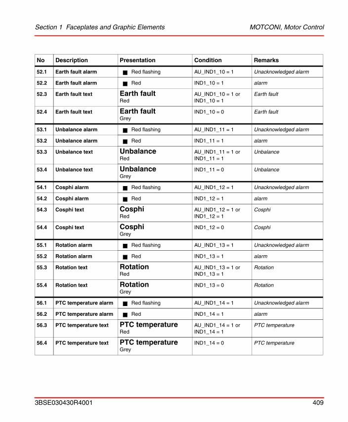
Section 1 Faceplates and Graphic Elements MOTCONI, Motor Control
52.1 Earth fault alarm Red flashing AU_IND1_10 = 1 Unacknowledged alarm
52.2 Earth fault alarm Red IND1_10 = 1 alarm
52.3 Earth fault text Earth faultRed
AU_IND1_10 = 1 orIND1_10 = 1
Earth fault
52.4 Earth fault text Earth faultGrey
IND1_10 = 0 Earth fault
53.1 Unbalance alarm Red flashing AU_IND1_11 = 1 Unacknowledged alarm
53.2 Unbalance alarm Red IND1_11 = 1 alarm
53.3 Unbalance text UnbalanceRed
AU_IND1_11 = 1 orIND1_11 = 1
Unbalance
53.4 Unbalance text UnbalanceGrey
IND1_11 = 0 Unbalance
54.1 Cosphi alarm Red flashing AU_IND1_12 = 1 Unacknowledged alarm
54.2 Cosphi alarm Red IND1_12 = 1 alarm
54.3 Cosphi text CosphiRed
AU_IND1_12 = 1 orIND1_12 = 1
Cosphi
54.4 Cosphi text CosphiGrey
IND1_12 = 0 Cosphi
55.1 Rotation alarm Red flashing AU_IND1_13 = 1 Unacknowledged alarm
55.2 Rotation alarm Red IND1_13 = 1 alarm
55.3 Rotation text RotationRed
AU_IND1_13 = 1 orIND1_13 = 1
Rotation
55.4 Rotation text RotationGrey
IND1_13 = 0 Rotation
56.1 PTC temperature alarm Red flashing AU_IND1_14 = 1 Unacknowledged alarm
56.2 PTC temperature alarm Red IND1_14 = 1 alarm
56.3 PTC temperature text PTC temperatureRed
AU_IND1_14 = 1 orIND1_14 = 1
PTC temperature
56.4 PTC temperature text PTC temperatureGrey
IND1_14 = 0 PTC temperature
No Description Presentation Condition Remarks
3BSE030430R4001 409
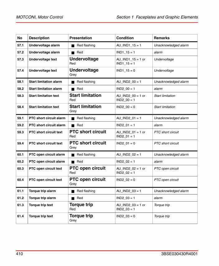
MOTCONI, Motor Control Section 1 Faceplates and Graphic Elements
57.1 Undervoltage alarm Red flashing AU_IND1_15 = 1 Unacknowledged alarm
57.2 Undervoltage alarm Red IND1_15 = 1 alarm
57.3 Undervoltage text UndervoltageRed
AU_IND1_15 = 1 orIND1_15 = 1
Undervoltage
57.4 Undervoltage text UndervoltageGrey
IND1_15 = 0 Undervoltage
58.1 Start limitation alarm Red flashing AU_IND2_00 = 1 Unacknowledged alarm
58.2 Start limitation alarm Red IND2_00 = 1 alarm
58.3 Start limitation text Start limitationRed
AU_IND2_00 = 1 orIND2_00 = 1
Start limitation
58.4 Start limitation text Start limitationGrey
IND2_00 = 0 Start limitation
59.1 PTC short circuit alarm Red flashing AU_IND2_01 = 1 Unacknowledged alarm
59.2 PTC short circuit alarm Red IND2_01 = 1 alarm
59.3 PTC short circuit text PTC short circuitRed
AU_IND2_01 = 1 orIND2_01 = 1
PTC short circuit
59.4 PTC short circuit text PTC short circuitGrey
IND2_01 = 0 PTC short circuit
60.1 PTC open circuit alarm Red flashing AU_IND2_02 = 1 Unacknowledged alarm
60.2 PTC open circuit alarm Red IND2_02 = 1 alarm
60.3 PTC open circuit text PTC open circuitRed
AU_IND2_02 = 1 orIND2_02 = 1
PTC open circuit
60.4 PTC open circuit text PTC open circuitGrey
IND2_02 = 0 PTC open circuit
61.1 Torque trip alarm Red flashing AU_IND2_03 = 1 Unacknowledged alarm
61.2 Torque trip alarm Red IND2_03 = 1 alarm
61.3 Torque trip text Torque tripRed
AU_IND2_03 = 1 orIND2_03 = 1
Torque trip
61.4 Torque trip text Torque tripGrey
IND2_03 = 0 Torque trip
No Description Presentation Condition Remarks
410 3BSE030430R4001
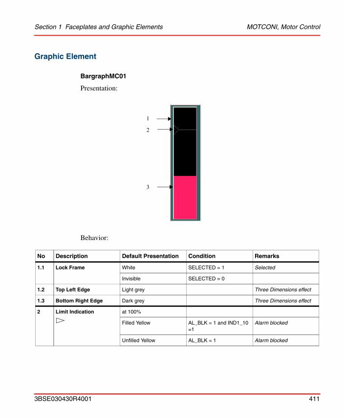
Section 1 Faceplates and Graphic Elements MOTCONI, Motor Control
Graphic Element
BargraphMC01
Presentation:
Behavior:
No Description Default Presentation Condition Remarks
1.1 Lock Frame White SELECTED = 1 Selected
Invisible SELECTED = 0
1.2 Top Left Edge Light grey Three Dimensions effect
1.3 Bottom Right Edge Dark grey Three Dimensions effect
2 Limit Indication at 100%
Filled Yellow AL_BLK = 1 and IND1_10 =1
Alarm blocked
Unfilled Yellow AL_BLK = 1 Alarm blocked
1
2
3
3BSE030430R4001 411
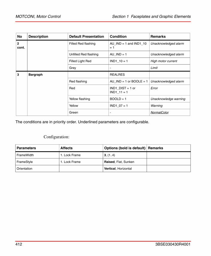
MOTCONI, Motor Control Section 1 Faceplates and Graphic Elements
The conditions are in priority order. Underlined parameters are configurable.
Configuration:
2 cont.
Filled Red flashing AU_IND = 1 and IND1_10 = 1
Unacknowledged alarm
Unfilled Red flashing AU_IND = 1 Unacknowledged alarm
Filled Light Red IND1_10 = 1 High motor current
Grey - Limit
3 Bargraph REALRES
Red flashing AU_IND = 1 or BOOLE = 1 Unacknowledged alarm
Red IND1_DIST = 1 or IND1_11 = 1
Error
Yellow flashing BOOLD = 1 Unacknowledge warning
Yellow IND1_07 = 1 Warning
Green - NormalColor
Parameters Affects Options (bold is default) Remarks
FrameWidth 1. Lock Frame 3, (1..4)
FrameStyle 1. Lock Frame Raised, Flat, Sunken
Orientation Vertical, Horizontal
No Description Default Presentation Condition Remarks
412 3BSE030430R4001
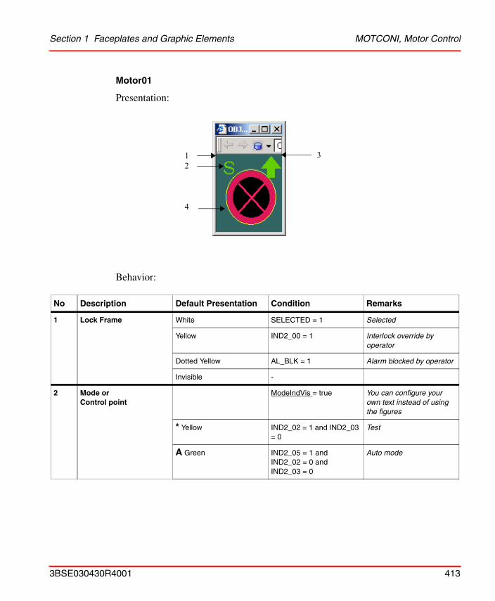
Section 1 Faceplates and Graphic Elements MOTCONI, Motor Control
Motor01
Presentation:
Behavior:
No Description Default Presentation Condition Remarks
1 Lock Frame White SELECTED = 1 Selected
Yellow IND2_00 = 1 Interlock override by operator
Dotted Yellow AL_BLK = 1 Alarm blocked by operator
Invisible -
2 Mode orControl point
ModeIndVis = true You can configure your own text instead of using the figures
* Yellow IND2_02 = 1 and IND2_03 = 0
Test
A Green IND2_05 = 1 andIND2_02 = 0 andIND2_03 = 0
Auto mode
1
4
32
3BSE030430R4001 413
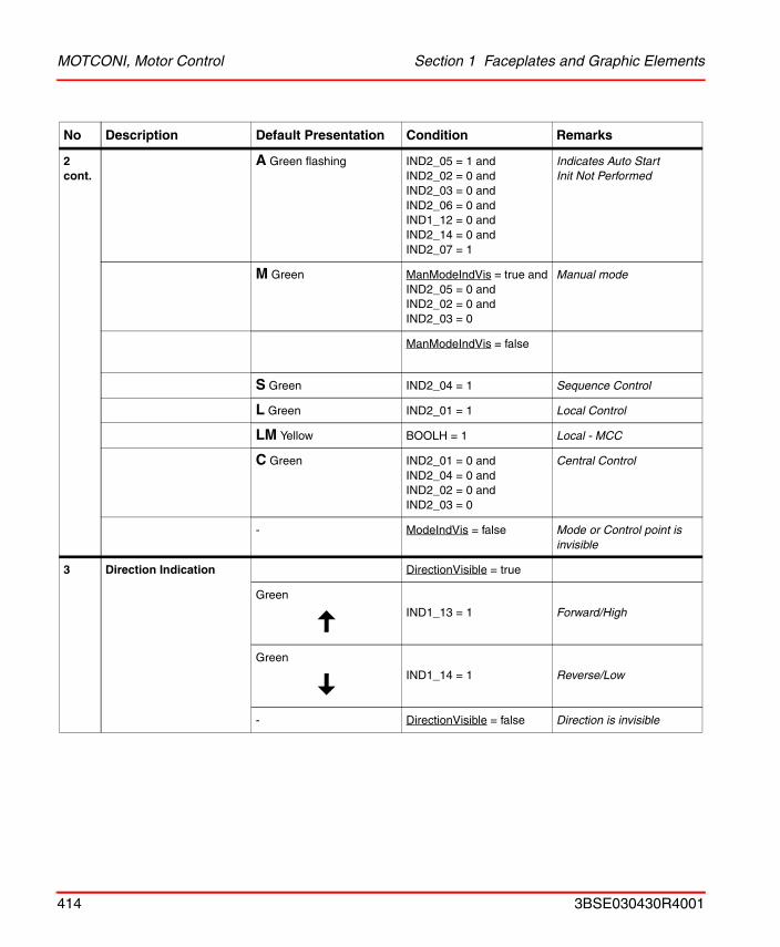
MOTCONI, Motor Control Section 1 Faceplates and Graphic Elements
2 cont.
A Green flashing IND2_05 = 1 andIND2_02 = 0 andIND2_03 = 0 andIND2_06 = 0 andIND1_12 = 0 andIND2_14 = 0 andIND2_07 = 1
Indicates Auto StartInit Not Performed
M Green ManModeIndVis = true andIND2_05 = 0 andIND2_02 = 0 andIND2_03 = 0
Manual mode
ManModeIndVis = false
S Green IND2_04 = 1 Sequence Control
L Green IND2_01 = 1 Local Control
LM Yellow BOOLH = 1 Local - MCC
C Green IND2_01 = 0 and IND2_04 = 0 and IND2_02 = 0 andIND2_03 = 0
Central Control
- ModeIndVis = false Mode or Control point is invisible
3 Direction Indication DirectionVisible = true
Green
IND1_13 = 1 Forward/High
Green
IND1_14 = 1 Reverse/Low
- DirectionVisible = false Direction is invisible
No Description Default Presentation Condition Remarks
414 3BSE030430R4001
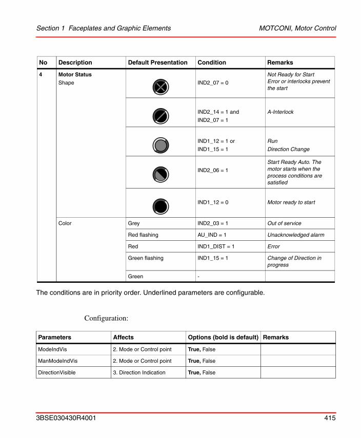
Section 1 Faceplates and Graphic Elements MOTCONI, Motor Control
The conditions are in priority order. Underlined parameters are configurable.
Configuration:
4 Motor Status
Shape IND2_07 = 0
Not Ready for StartError or interlocks prevent the start
IND2_14 = 1 and
IND2_07 = 1
A-Interlock
IND1_12 = 1 or
IND1_15 = 1
Run
Direction Change
IND2_06 = 1
Start Ready Auto. The motor starts when the process conditions are satisfied
IND1_12 = 0 Motor ready to start
Color Grey IND2_03 = 1 Out of service
Red flashing AU_IND = 1 Unacknowledged alarm
Red IND1_DIST = 1 Error
Green flashing IND1_15 = 1 Change of Direction in progress
Green -
Parameters Affects Options (bold is default) Remarks
ModeIndVis 2. Mode or Control point True, False
ManModeIndVis 2. Mode or Control point True, False
DirectionVisible 3. Direction Indication True, False
No Description Default Presentation Condition Remarks
3BSE030430R4001 415
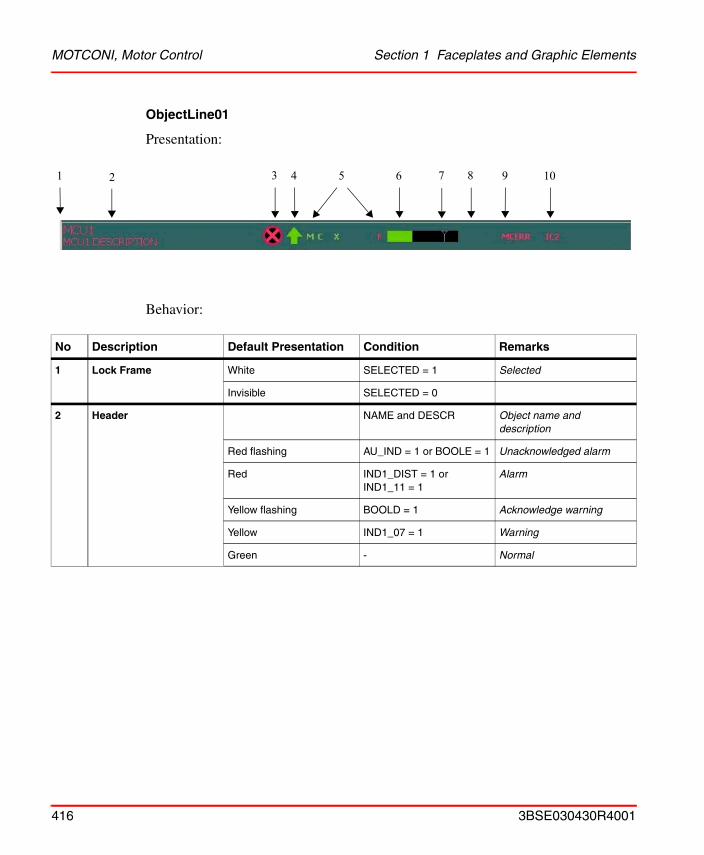
MOTCONI, Motor Control Section 1 Faceplates and Graphic Elements
ObjectLine01
Presentation:
Behavior:
No Description Default Presentation Condition Remarks
1 Lock Frame White SELECTED = 1 Selected
Invisible SELECTED = 0
2 Header NAME and DESCR Object name and description
Red flashing AU_IND = 1 or BOOLE = 1 Unacknowledged alarm
Red IND1_DIST = 1 or IND1_11 = 1
Alarm
Yellow flashing BOOLD = 1 Acknowledge warning
Yellow IND1_07 = 1 Warning
Green - Normal
1 2 3 4 5 6 7 8 9 10
416 3BSE030430R4001
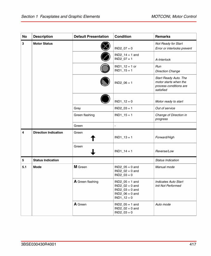
Section 1 Faceplates and Graphic Elements MOTCONI, Motor Control
3 Motor Status
IND2_07 = 0
Not Ready for Start
Error or interlocks prevent
IND2_14 = 1 andIND2_07 = 1 A-Interlock
IND1_12 = 1 orIND1_15 = 1
Run
Direction Change
IND2_06 = 1
Start Ready Auto. The motor starts when the process conditions are satisfied
IND1_12 = 0 Motor ready to start
Grey IND2_03 = 1 Out of service
Green flashing IND1_15 = 1 Change of Direction in progress
Green -
4 Direction Indication Green
IND1_13 = 1 Forward/High
Green
IND1_14 = 1 Reverse/Low
5 Status Indication Status Indication
5.1 Mode M Green IND2_05 = 0 andIND2_02 = 0 andIND2_03 = 0
Manual mode
A Green flashing IND2_05 = 1 andIND2_02 = 0 andIND2_03 = 0 andIND2_06 = 0 andIND1_12 = 0
Indicates Auto StartInit Not Performed
A Green IND2_05 = 1 andIND2_02 = 0 andIND2_03 = 0
Auto mode
No Description Default Presentation Condition Remarks
3BSE030430R4001 417
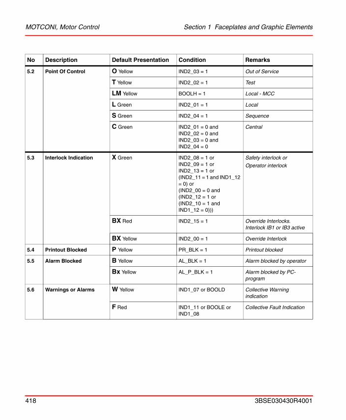
MOTCONI, Motor Control Section 1 Faceplates and Graphic Elements
5.2 Point Of Control O Yellow IND2_03 = 1 Out of Service
T Yellow IND2_02 = 1 Test
LM Yellow BOOLH = 1 Local - MCC
L Green IND2_01 = 1 Local
S Green IND2_04 = 1 Sequence
C Green IND2_01 = 0 andIND2_02 = 0 andIND2_03 = 0 andIND2_04 = 0
Central
5.3 Interlock Indication X Green IND2_08 = 1 orIND2_09 = 1 orIND2_13 = 1 or(IND2_11 = 1 and IND1_12 = 0) or(IND2_00 = 0 and(IND2_12 = 1 or(IND2_10 = 1 and IND1_12 = 0)))
Safety interlock or
Operator interlock
BX Red IND2_15 = 1 Override Interlocks. Interlock IB1 or IB3 active
BX Yellow IND2_00 = 1 Override Interlock
5.4 Printout Blocked P Yellow PR_BLK = 1 Printout blocked
5.5 Alarm Blocked B Yellow AL_BLK = 1 Alarm blocked by operator
Bx Yellow AL_P_BLK = 1 Alarm blocked by PC-program
5.6 Warnings or Alarms W Yellow IND1_07 or BOOLD Collective Warning indication
F Red IND1_11 or BOOLE or IND1_08
Collective Fault Indication
No Description Default Presentation Condition Remarks
418 3BSE030430R4001
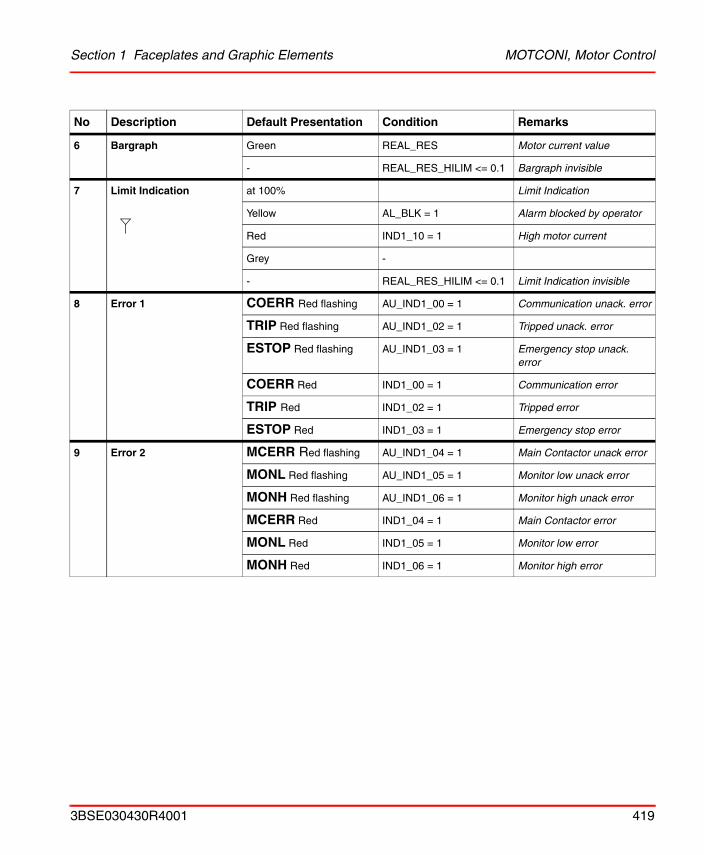
Section 1 Faceplates and Graphic Elements MOTCONI, Motor Control
6 Bargraph Green REAL_RES Motor current value
- REAL_RES_HILIM <= 0.1 Bargraph invisible
7 Limit Indication at 100% Limit Indication
Yellow AL_BLK = 1 Alarm blocked by operator
Red IND1_10 = 1 High motor current
Grey -
- REAL_RES_HILIM <= 0.1 Limit Indication invisible
8 Error 1 COERR Red flashing AU_IND1_00 = 1 Communication unack. error
TRIP Red flashing AU_IND1_02 = 1 Tripped unack. error
ESTOP Red flashing AU_IND1_03 = 1 Emergency stop unack. error
COERR Red IND1_00 = 1 Communication error
TRIP Red IND1_02 = 1 Tripped error
ESTOP Red IND1_03 = 1 Emergency stop error
9 Error 2 MCERR Red flashing AU_IND1_04 = 1 Main Contactor unack error
MONL Red flashing AU_IND1_05 = 1 Monitor low unack error
MONH Red flashing AU_IND1_06 = 1 Monitor high unack error
MCERR Red IND1_04 = 1 Main Contactor error
MONL Red IND1_05 = 1 Monitor low error
MONH Red IND1_06 = 1 Monitor high error
No Description Default Presentation Condition Remarks
3BSE030430R4001 419
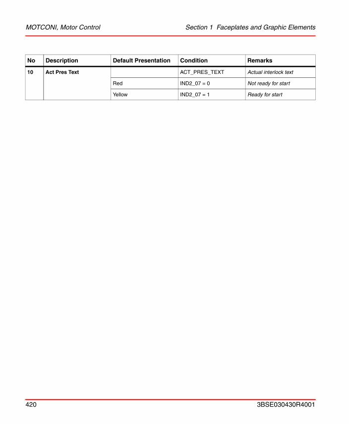
MOTCONI, Motor Control Section 1 Faceplates and Graphic Elements
10 Act Pres Text ACT_PRES_TEXT Actual interlock text
Red IND2_07 = 0 Not ready for start
Yellow IND2_07 = 1 Ready for start
No Description Default Presentation Condition Remarks
420 3BSE030430R4001
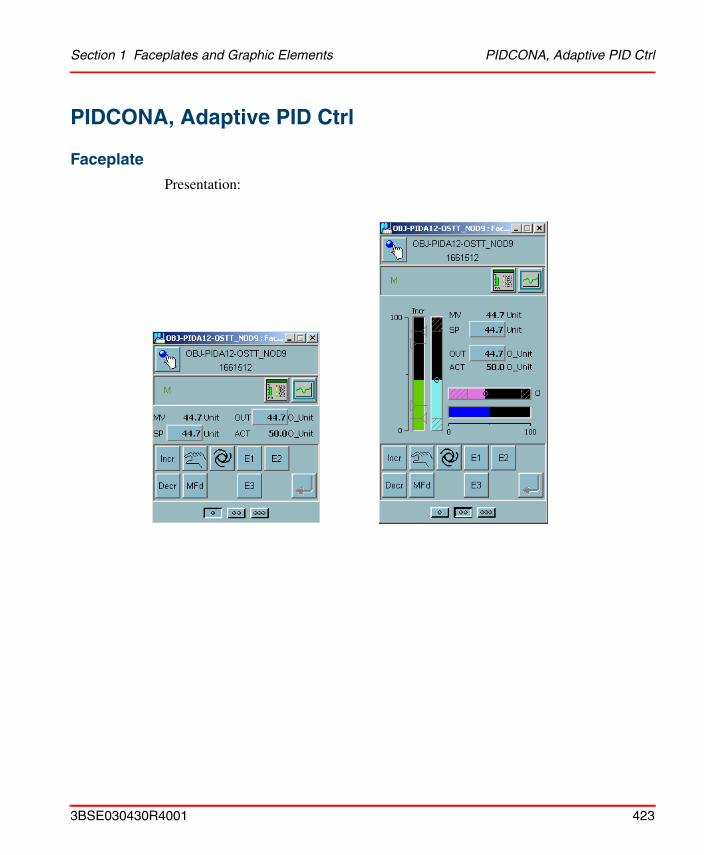
Section 1 Faceplates and Graphic Elements PIDCONA, Adaptive PID Ctrl
PIDCONA, Adaptive PID Ctrl
Faceplate
Presentation:
3BSE030430R4001 423
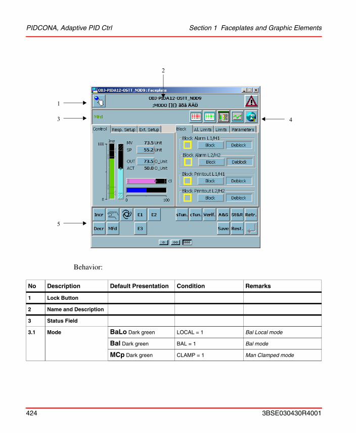
PIDCONA, Adaptive PID Ctrl Section 1 Faceplates and Graphic Elements
Behavior:
No Description Default Presentation Condition Remarks
1 Lock Button
2 Name and Description
3 Status Field
3.1 Mode BaLo Dark green LOCAL = 1 Bal Local mode
Bal Dark green BAL = 1 Bal mode
MCp Dark green CLAMP = 1 Man Clamped mode
1
3
5
4
2
424 3BSE030430R4001
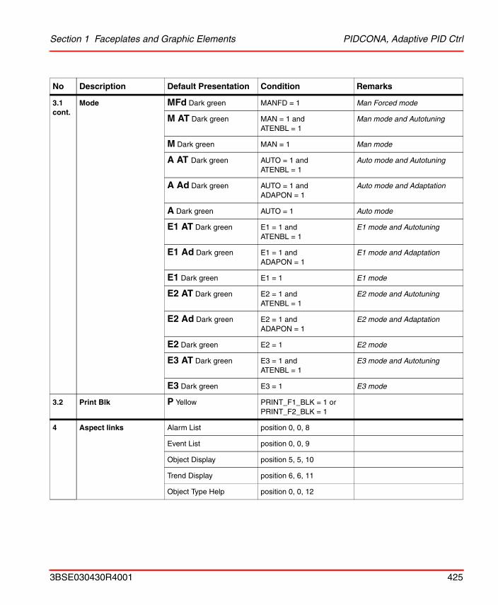
Section 1 Faceplates and Graphic Elements PIDCONA, Adaptive PID Ctrl
3.1 cont.
Mode MFd Dark green MANFD = 1 Man Forced mode
M AT Dark green MAN = 1 andATENBL = 1
Man mode and Autotuning
M Dark green MAN = 1 Man mode
A AT Dark green AUTO = 1 andATENBL = 1
Auto mode and Autotuning
A Ad Dark green AUTO = 1 andADAPON = 1
Auto mode and Adaptation
A Dark green AUTO = 1 Auto mode
E1 AT Dark green E1 = 1 andATENBL = 1
E1 mode and Autotuning
E1 Ad Dark green E1 = 1 andADAPON = 1
E1 mode and Adaptation
E1 Dark green E1 = 1 E1 mode
E2 AT Dark green E2 = 1 andATENBL = 1
E2 mode and Autotuning
E2 Ad Dark green E2 = 1 andADAPON = 1
E2 mode and Adaptation
E2 Dark green E2 = 1 E2 mode
E3 AT Dark green E3 = 1 andATENBL = 1
E3 mode and Autotuning
E3 Dark green E3 = 1 E3 mode
3.2 Print Blk P Yellow PRINT_F1_BLK = 1 orPRINT_F2_BLK = 1
4 Aspect links Alarm List position 0, 0, 8
Event List position 0, 0, 9
Object Display position 5, 5, 10
Trend Display position 6, 6, 11
Object Type Help position 0, 0, 12
No Description Default Presentation Condition Remarks
3BSE030430R4001 425
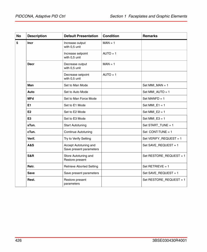
PIDCONA, Adaptive PID Ctrl Section 1 Faceplates and Graphic Elements
5 Incr Increase outputwith 0,5 unit
MAN = 1
Increase setpointwith 0,5 unit
AUTO = 1
Decr Decrease outputwith 0,5 unit
MAN = 1
Decrease setpointwith 0,5 unit
AUTO = 1
Man Set to Man Mode Set MMI_MAN = 1
Auto Set to Auto Mode Set MMI_AUTO = 1
MFd Set to Man Force Mode Set MANFD = 1
E1 Set to E1 Mode Set MMI_E1 = 1
E2 Set to E2 Mode Set MMI_E2 = 1
E3 Set to E3 Mode Set MMI_E3 = 1
sTun. Start Autotuning Set START_TUNE = 1
cTun. Continue Autotuning Set CONT-TUNE = 1
Verif. Try to Verify Setting Set VERIFY_REQUEST = 1
A&S Accept Autotuning and Save present parameters
Set SAVE_REQUEST = 1
S&R Store Autotuning and Restore present
Set RESTORE_REQUEST = 1
Retr. Retrieve Aborted Setting Set RETRIEVE = 1
Save Save present parameters Set SAVE_REQUEST = 1
Rest. Restore present parameters
Set RESTORE_REQUEST = 1
No Description Default Presentation Condition Remarks
426 3BSE030430R4001
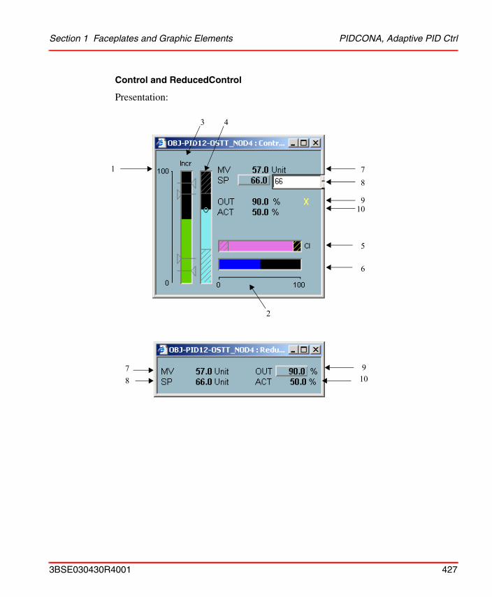
Section 1 Faceplates and Graphic Elements PIDCONA, Adaptive PID Ctrl
Control and ReducedControl
Presentation:
8
9
7
6
1
3 4
10
5
2
910
78
3BSE030430R4001 427
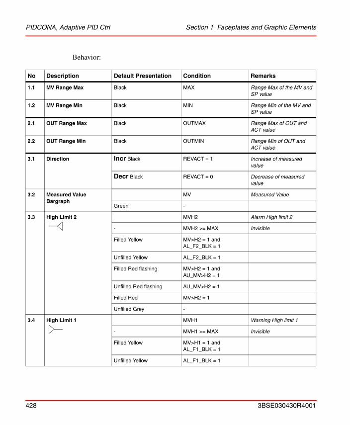
PIDCONA, Adaptive PID Ctrl Section 1 Faceplates and Graphic Elements
Behavior:
No Description Default Presentation Condition Remarks
1.1 MV Range Max Black MAX Range Max of the MV and SP value
1.2 MV Range Min Black MIN Range Min of the MV and SP value
2.1 OUT Range Max Black OUTMAX Range Max of OUT and ACT value
2.2 OUT Range Min Black OUTMIN Range Min of OUT and ACT value
3.1 Direction Incr Black REVACT = 1 Increase of measured value
Decr Black REVACT = 0 Decrease of measured value
3.2 Measured Value Bargraph
MV Measured Value
Green -
3.3 High Limit 2 MVH2 Alarm High limit 2
- MVH2 >= MAX Invisible
Filled Yellow MV>H2 = 1 and AL_F2_BLK = 1
Unfilled Yellow AL_F2_BLK = 1
Filled Red flashing MV>H2 = 1 and AU_MV>H2 = 1
Unfilled Red flashing AU_MV>H2 = 1
Filled Red MV>H2 = 1
Unfilled Grey -
3.4 High Limit 1 MVH1 Warning High limit 1
- MVH1 >= MAX Invisible
Filled Yellow MV>H1 = 1 and AL_F1_BLK = 1
Unfilled Yellow AL_F1_BLK = 1
428 3BSE030430R4001
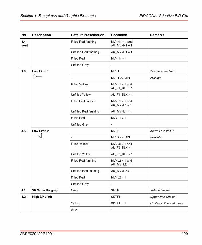
Section 1 Faceplates and Graphic Elements PIDCONA, Adaptive PID Ctrl
3.4 cont.
Filled Red flashing MV>H1 = 1 and AU_MV>H1 = 1
Unfilled Red flashing AU_MV>H1 = 1
Filled Red MV>H1 = 1
Unfilled Grey -
3.5 Low Limit 1 MVL1 Warning Low limit 1
- MVL1 <= MIN Invisible
Filled Yellow MV<L1 = 1 and AL_F1_BLK = 1
Unfilled Yellow AL_F1_BLK = 1
Filled Red flashing MV<L1 = 1 and AU_MV<L1 = 1
Unfilled Red flashing AU_MV<L1 = 1
Filled Red MV<L1 = 1
Unfilled Grey -
3.6 Low Limit 2 MVL2 Alarm Low limit 2
- MVL2 <= MIN Invisible
Filled Yellow MV<L2 = 1 and AL_F2_BLK = 1
Unfilled Yellow AL_F2_BLK = 1
Filled Red flashing MV<L2 = 1 and AU_MV<L2 = 1
Unfilled Red flashing AU_MV<L2 = 1
Filled Red MV<L2 = 1
Unfilled Grey -
4.1 SP Value Bargraph Cyan SETP Setpoint value
4.2 High SP Limit SETPH Upper limit setpoint
Yellow SP=HL = 1 Limitation line and mesh
Grey -
No Description Default Presentation Condition Remarks
3BSE030430R4001 429
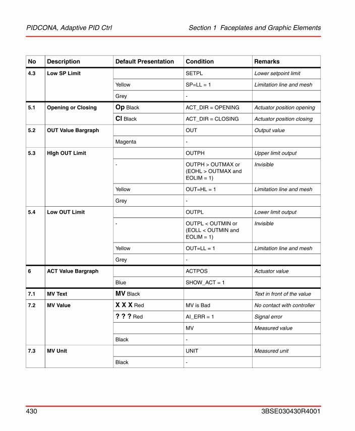
PIDCONA, Adaptive PID Ctrl Section 1 Faceplates and Graphic Elements
4.3 Low SP Limit SETPL Lower setpoint limit
Yellow SP=LL = 1 Limitation line and mesh
Grey -
5.1 Opening or Closing Op Black ACT_DIR = OPENING Actuator position opening
Cl Black ACT_DIR = CLOSING Actuator position closing
5.2 OUT Value Bargraph OUT Output value
Magenta -
5.3 HIgh OUT Limit OUTPH Upper limit output
- OUTPH > OUTMAX or(EOHL > OUTMAX andEOLIM = 1)
Invisible
Yellow OUT=HL = 1 Limitation line and mesh
Grey -
5.4 Low OUT Limit OUTPL Lower limit output
- OUTPL < OUTMIN or(EOLL < OUTMIN andEOLIM = 1)
Invisible
Yellow OUT=LL = 1 Limitation line and mesh
Grey -
6 ACT Value Bargraph ACTPOS Actuator value
Blue SHOW_ACT = 1
7.1 MV Text MV Black Text in front of the value
7.2 MV Value X X X Red MV is Bad No contact with controller
? ? ? Red AI_ERR = 1 Signal error
MV Measured value
Black -
7.3 MV Unit UNIT Measured unit
Black -
No Description Default Presentation Condition Remarks
430 3BSE030430R4001
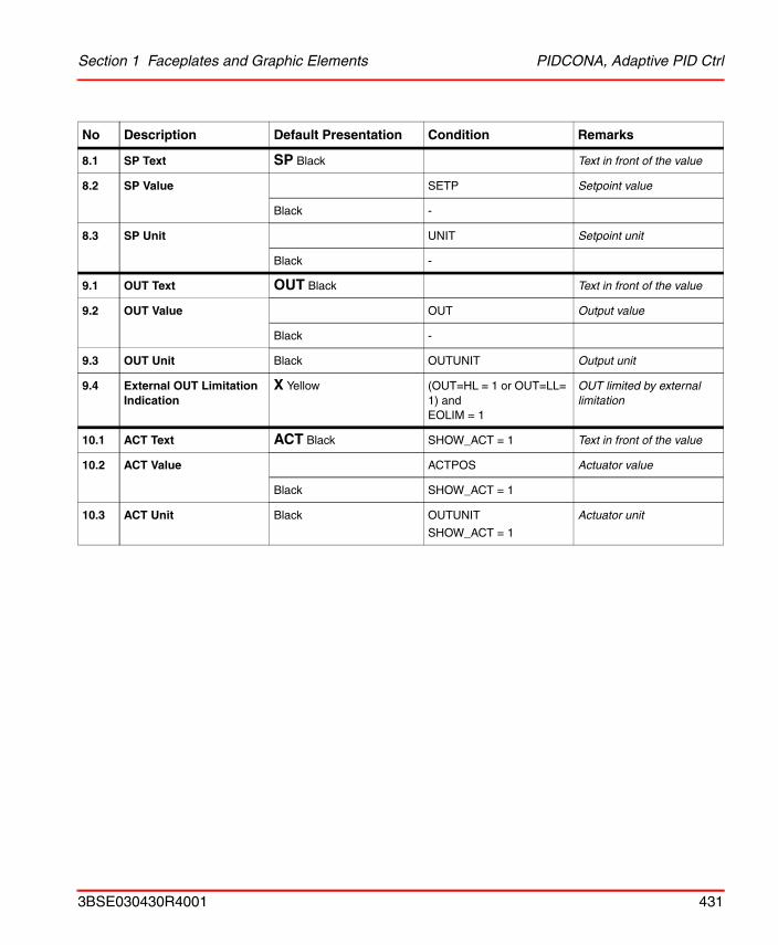
Section 1 Faceplates and Graphic Elements PIDCONA, Adaptive PID Ctrl
8.1 SP Text SP Black Text in front of the value
8.2 SP Value SETP Setpoint value
Black -
8.3 SP Unit UNIT Setpoint unit
Black -
9.1 OUT Text OUT Black Text in front of the value
9.2 OUT Value OUT Output value
Black -
9.3 OUT Unit Black OUTUNIT Output unit
9.4 External OUT Limitation Indication
X Yellow (OUT=HL = 1 or OUT=LL= 1) and EOLIM = 1
OUT limited by external limitation
10.1 ACT Text ACT Black SHOW_ACT = 1 Text in front of the value
10.2 ACT Value ACTPOS Actuator value
Black SHOW_ACT = 1
10.3 ACT Unit Black OUTUNIT
SHOW_ACT = 1
Actuator unit
No Description Default Presentation Condition Remarks
3BSE030430R4001 431
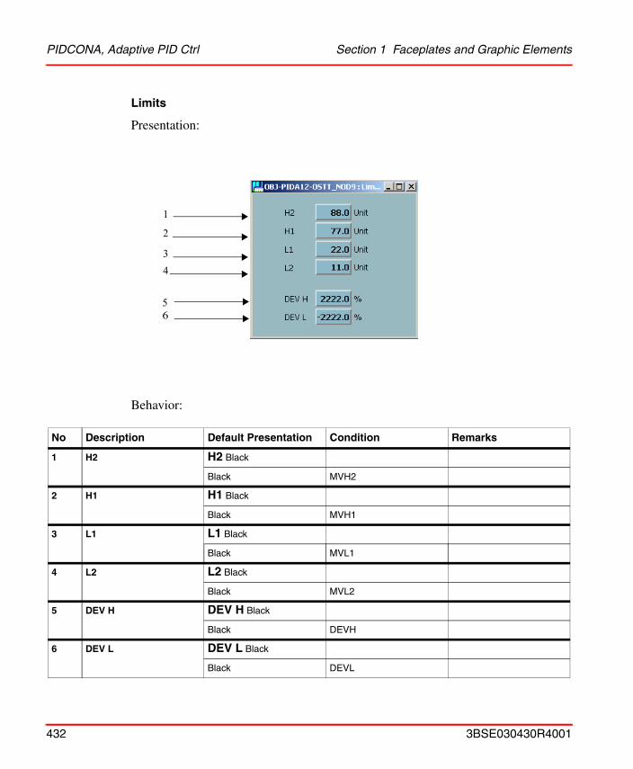
PIDCONA, Adaptive PID Ctrl Section 1 Faceplates and Graphic Elements
Limits
Presentation:
Behavior:
No Description Default Presentation Condition Remarks
1 H2 H2 Black
Black MVH2
2 H1 H1 Black
Black MVH1
3 L1 L1 Black
Black MVL1
4 L2 L2 Black
Black MVL2
5 DEV H DEV H Black
Black DEVH
6 DEV L DEV L Black
Black DEVL
1
2
3
56
4
432 3BSE030430R4001
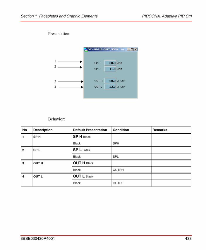
Section 1 Faceplates and Graphic Elements PIDCONA, Adaptive PID Ctrl
Presentation:
Behavior:
No Description Default Presentation Condition Remarks
1 SP H SP H Black
Black SPH
2 SP L SP L Black
Black SPL
3 OUT H OUT H Black
Black OUTPH
4 OUT L OUT L Black
Black OUTPL
12
43
3BSE030430R4001 433
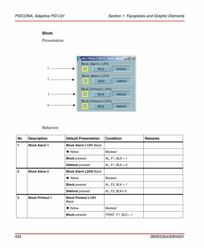
PIDCONA, Adaptive PID Ctrl Section 1 Faceplates and Graphic Elements
Block
Presentation:
Behavior:
No Description Default Presentation Condition Remarks
1 Block Alarm 1 Block Alarm L1/H1 Black
! Yellow Blocked
Block pressed AL_F1_BLK = 1
Deblock pressed AL_F1_BLK = 0
2 Block Alarm 2 Block Alarm L2/H2 Black
! Yellow Blocked
Block pressed AL_F2_BLK = 1
Deblock pressed AL_F2_BLK= 0
3 Block Printout 1 Block Printout L1/H1 Black
! Yellow Blocked
Block pressed PRINT_F1_BLK = 1
1
2
3
4
434 3BSE030430R4001
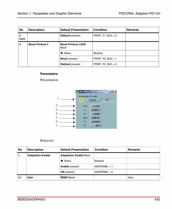
Section 1 Faceplates and Graphic Elements PIDCONA, Adaptive PID Ctrl
Parameters
Presentation:
Behavior:
3 cont.
Deblock pressed PRINT_F1_BLK = 0
4 Block Printout 2 Block Printout L2/H2 Black
! Yellow Blocked
Block pressed PRINT_F2_BLK = 1
Deblock pressed PRINT_F2_BLK = 0
No Description Default Presentation Condition Remarks
1 Adaptation Enable Adaptation Enable Black
! Yellow Blocked
Enable pressed ADAPENBL = 1
Off pressed ADAPENBL = 0
2.1 Gain Gain Black Gain
No Description Default Presentation Condition Remarks
3
65
2
1
4
7
3BSE030430R4001 435
PIDCONA, Adaptive PID Ctrl Section 1 Faceplates and Graphic Elements
2.2 Value Black GAIN
3.1 TI TI Black Integration time
3.2 Value Black TI
3.3 Unit s Black
4.1 TD TD Black Derivation time
4.2 Value Black TD
4.3 Unit s Black
5.1 BETA BETA Black Setpoint factor BETA
5.2 Value Black BETA
6.1 TS TS Black Sampling time
6.2 Value Black TS
6.3 Unit s Black
7.1 DZ DZ Black Dead zone
7.2 Value Black DZ, CTRL = ON - OFF
7.3 Unit % Black DZ, CTRL = ON - OFF
No Description Default Presentation Condition Remarks
436 3BSE030430R4001
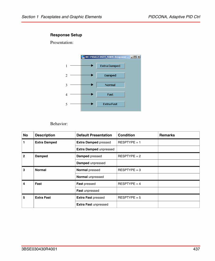
Section 1 Faceplates and Graphic Elements PIDCONA, Adaptive PID Ctrl
Response Setup
Presentation:
Behavior:
No Description Default Presentation Condition Remarks
1 Extra Damped Extra Damped pressed RESPTYPE = 1
Extra Damped unpressed
2 Damped Damped pressed RESPTYPE = 2
Damped unpressed
3 Normal Normal pressed RESPTYPE = 3
Normal unpressed
4 Fast Fast pressed RESPTYPE = 4
Fast unpressed
5 Extra Fast Extra Fast pressed RESPTYPE = 5
Extra Fast unpressed
1
2
3
4
5
3BSE030430R4001 437
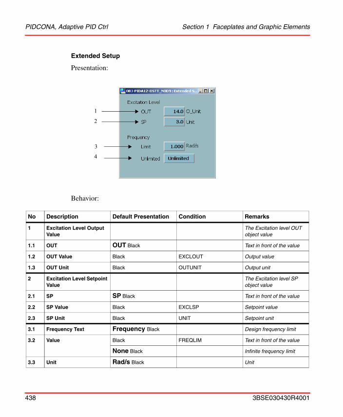
PIDCONA, Adaptive PID Ctrl Section 1 Faceplates and Graphic Elements
Extended Setup
Presentation:
Behavior:
No Description Default Presentation Condition Remarks
1 Excitation Level Output Value
The Excitation level OUT object value
1.1 OUT OUT Black Text in front of the value
1.2 OUT Value Black EXCLOUT Output value
1.3 OUT Unit Black OUTUNIT Output unit
2 Excitation Level Setpoint Value
The Excitation level SP object value
2.1 SP SP Black Text in front of the value
2.2 SP Value Black EXCLSP Setpoint value
2.3 SP Unit Black UNIT Setpoint unit
3.1 Frequency Text Frequency Black Design frequency limit
3.2 Value Black FREQLIM Text in front of the value
None Black Infinite frequency limit
3.3 Unit Rad/s Black Unit
2
1
4
3
438 3BSE030430R4001
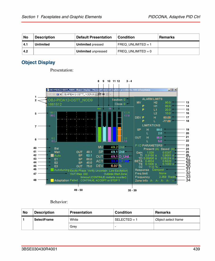
Section 1 Faceplates and Graphic Elements PIDCONA, Adaptive PID Ctrl
Object Display
Presentation:
Behavior:
4.1 Unlimited Unlimited pressed FREQ_UNLIMITED = 1
4.2 Unlimited unpressed FREQ_UNLIMITED = 0
No Description Presentation Condition Remarks
1 SelectFrame White SELECTED = 1 Object select frame
Grey -
No Description Default Presentation Condition Remarks
1413
15
17
1920
23
22
26
16
24
27
25
21
18
28293031323334
49 - 50
48
47
46
35 - 39
8 9 10 11 12 3 - 4
45
12
5
7
6
4041424344
3BSE030430R4001 439
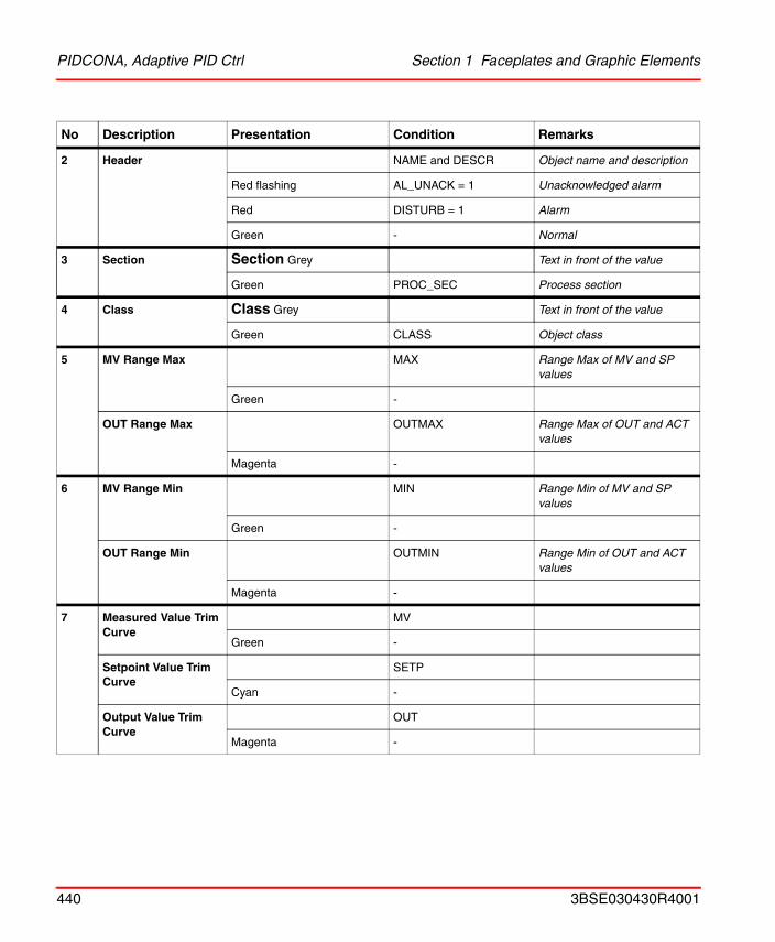
PIDCONA, Adaptive PID Ctrl Section 1 Faceplates and Graphic Elements
2 Header NAME and DESCR Object name and description
Red flashing AL_UNACK = 1 Unacknowledged alarm
Red DISTURB = 1 Alarm
Green - Normal
3 Section Section Grey Text in front of the value
Green PROC_SEC Process section
4 Class Class Grey Text in front of the value
Green CLASS Object class
5 MV Range Max MAX Range Max of MV and SP values
Green -
OUT Range Max OUTMAX Range Max of OUT and ACT values
Magenta -
6 MV Range Min MIN Range Min of MV and SP values
Green -
OUT Range Min OUTMIN Range Min of OUT and ACT values
Magenta -
7 Measured Value Trim Curve
MV
Green -
Setpoint Value Trim Curve
SETP
Cyan -
Output Value Trim Curve
OUT
Magenta -
No Description Presentation Condition Remarks
440 3BSE030430R4001
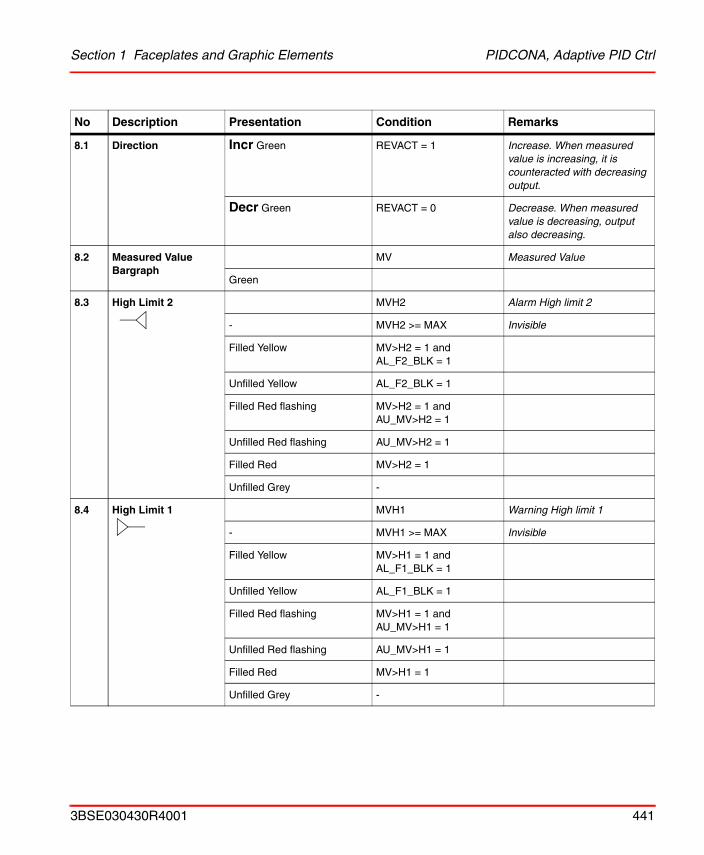
Section 1 Faceplates and Graphic Elements PIDCONA, Adaptive PID Ctrl
8.1 Direction Incr Green REVACT = 1 Increase. When measured value is increasing, it is counteracted with decreasing output.
Decr Green REVACT = 0 Decrease. When measured value is decreasing, output also decreasing.
8.2 Measured Value Bargraph
MV Measured Value
Green
8.3 High Limit 2 MVH2 Alarm High limit 2
- MVH2 >= MAX Invisible
Filled Yellow MV>H2 = 1 and AL_F2_BLK = 1
Unfilled Yellow AL_F2_BLK = 1
Filled Red flashing MV>H2 = 1 and AU_MV>H2 = 1
Unfilled Red flashing AU_MV>H2 = 1
Filled Red MV>H2 = 1
Unfilled Grey -
8.4 High Limit 1 MVH1 Warning High limit 1
- MVH1 >= MAX Invisible
Filled Yellow MV>H1 = 1 and AL_F1_BLK = 1
Unfilled Yellow AL_F1_BLK = 1
Filled Red flashing MV>H1 = 1 and AU_MV>H1 = 1
Unfilled Red flashing AU_MV>H1 = 1
Filled Red MV>H1 = 1
Unfilled Grey -
No Description Presentation Condition Remarks
3BSE030430R4001 441
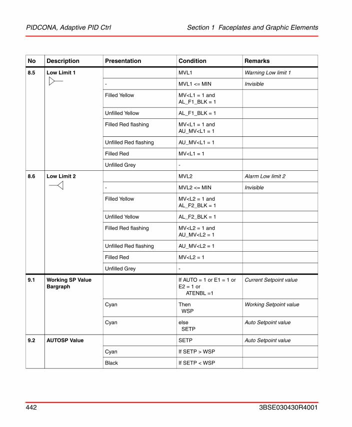
PIDCONA, Adaptive PID Ctrl Section 1 Faceplates and Graphic Elements
8.5 Low Limit 1 MVL1 Warning Low limit 1
- MVL1 <= MIN Invisible
Filled Yellow MV<L1 = 1 and AL_F1_BLK = 1
Unfilled Yellow AL_F1_BLK = 1
Filled Red flashing MV<L1 = 1 and AU_MV<L1 = 1
Unfilled Red flashing AU_MV<L1 = 1
Filled Red MV<L1 = 1
Unfilled Grey -
8.6 Low Limit 2 MVL2 Alarm Low limit 2
- MVL2 <= MIN Invisible
Filled Yellow MV<L2 = 1 and AL_F2_BLK = 1
Unfilled Yellow AL_F2_BLK = 1
Filled Red flashing MV<L2 = 1 and AU_MV<L2 = 1
Unfilled Red flashing AU_MV<L2 = 1
Filled Red MV<L2 = 1
Unfilled Grey -
9.1 Working SP Value Bargraph
If AUTO = 1 or E1 = 1 or E2 = 1 or
ATENBL =1
Current Setpoint value
Cyan Then WSP
Working Setpoint value
Cyan elseSETP
Auto Setpoint value
9.2 AUTOSP Value SETP Auto Setpoint value
Cyan If SETP > WSP
Black If SETP < WSP
No Description Presentation Condition Remarks
442 3BSE030430R4001
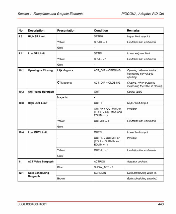
Section 1 Faceplates and Graphic Elements PIDCONA, Adaptive PID Ctrl
9.3 High SP Limit SETPH Upper limit setpoint
Yellow SP=HL = 1 Limitation line and mesh
Grey -
9.4 Low SP Limit SETPL Lower setpoint limit
Yellow SP=LL = 1 Limitation line and mesh
Grey -
10.1 Opening or Closing Op Magenta ACT_DIR = OPENING Opening. When output is increasing the valve is opening.
Cl Magenta ACT_DIR = CLOSING Closing. When output is increasing the valve is closing.
10.2 OUT Value Bargraph OUT Output value
Magenta -
10.3 HIgh OUT Limit OUTPH Upper limit output
- OUTPH > OUTMAX or(EOHL > OUTMAX andEOLIM = 1)
Invisible
Yellow OUT=HL = 1 Limitation line and mesh
Grey -
10.4 Low OUT Limit OUTPL Lower limit output
- OUTPL < OUTMIN or(EOLL < OUTMIN andEOLIM = 1)
Invisible
Yellow OUT=LL = 1 Limitation line and mesh
Grey -
11 ACT Value Bargraph ACTPOS Actuator position.
Blue SHOW_ACT = 1
12.1 Gain Scheduling Bargraph
SCHEDIN Gain scheduling value in.
Brown Gain scheduling enabled.
No Description Presentation Condition Remarks
3BSE030430R4001 443
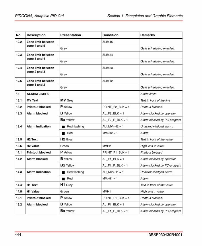
PIDCONA, Adaptive PID Ctrl Section 1 Faceplates and Graphic Elements
12.2 Zone limit between zone 4 and 5
ZLIM45
Grey Gain scheduling enabled.
12.3 Zone limit between zone 3 and 4
ZLIM34
Grey Gain scheduling enabled.
12.4 Zone limit between zone 2 and 3
ZLIM23
Grey Gain scheduling enabled.
12.5 Zone limit betweenzone 1 and 2
ZLIM12
Grey Gain scheduling enabled.
13 ALARM LIMITS Alarm limits
13.1 MV Text MV Grey Text in front of the line
13.2 Printout blocked P Yellow PRINT_F2_BLK = 1 Printout blocked.
13.3 Alarm blocked B Yellow AL_F2_BLK = 1 Alarm blocked by operator.
Bx Yellow AL_F2_P_BLK = 1 Alarm blocked by PC-program
13.4 Alarm Indication Red flashing AU_MV>H2 = 1 Unacknowledged alarm.
Red MV>H2 = 1 Alarm.
13.5 H2 Text H2 Grey Text in front of the value
13.6 H2 Value Green MVH2 High limit 2 value
14.1 Printout blocked P Yellow PRINT_F1_BLK = 1 Printout blocked
14.2 Alarm blocked B Yellow AL_F1_BLK = 1 Alarm blocked by operator.
Bx Yellow AL_F1_P_BLK = 1 Alarm blocked by PC-program
14.3 Alarm Indication Red flashing AU_MV>H1 = 1 Unacknowledged alarm.
Red MV>H1 = 1 Alarm.
14.4 H1 Text H1 Grey Text in front of the value
14.5 H1 Value Green MVH1 High limit 1 value
15.1 Printout blocked P Yellow PRINT_F1_BLK = 1 Printout blocked.
15.2 Alarm blocked B Yellow AL_F1_BLK = 1 Alarm blocked by operator.
Bx Yellow AL_F1_P_BLK = 1 Alarm blocked by PC-program
No Description Presentation Condition Remarks
444 3BSE030430R4001
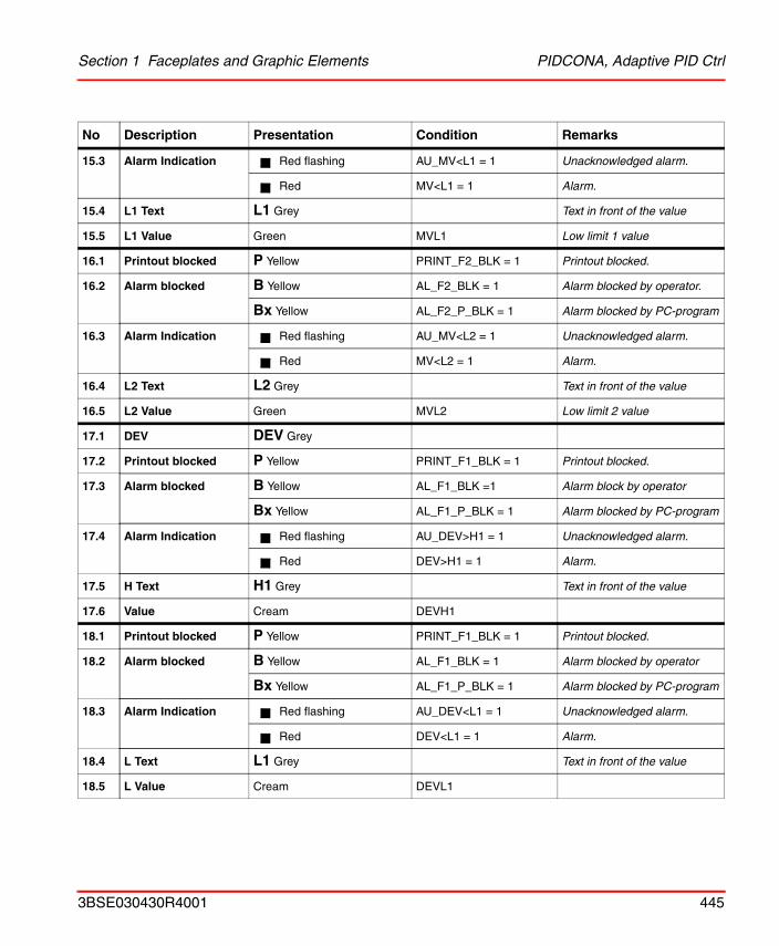
Section 1 Faceplates and Graphic Elements PIDCONA, Adaptive PID Ctrl
15.3 Alarm Indication Red flashing AU_MV<L1 = 1 Unacknowledged alarm.
Red MV<L1 = 1 Alarm.
15.4 L1 Text L1 Grey Text in front of the value
15.5 L1 Value Green MVL1 Low limit 1 value
16.1 Printout blocked P Yellow PRINT_F2_BLK = 1 Printout blocked.
16.2 Alarm blocked B Yellow AL_F2_BLK = 1 Alarm blocked by operator.
Bx Yellow AL_F2_P_BLK = 1 Alarm blocked by PC-program
16.3 Alarm Indication Red flashing AU_MV<L2 = 1 Unacknowledged alarm.
Red MV<L2 = 1 Alarm.
16.4 L2 Text L2 Grey Text in front of the value
16.5 L2 Value Green MVL2 Low limit 2 value
17.1 DEV DEV Grey
17.2 Printout blocked P Yellow PRINT_F1_BLK = 1 Printout blocked.
17.3 Alarm blocked B Yellow AL_F1_BLK =1 Alarm block by operator
Bx Yellow AL_F1_P_BLK = 1 Alarm blocked by PC-program
17.4 Alarm Indication Red flashing AU_DEV>H1 = 1 Unacknowledged alarm.
Red DEV>H1 = 1 Alarm.
17.5 H Text H1 Grey Text in front of the value
17.6 Value Cream DEVH1
18.1 Printout blocked P Yellow PRINT_F1_BLK = 1 Printout blocked.
18.2 Alarm blocked B Yellow AL_F1_BLK = 1 Alarm blocked by operator
Bx Yellow AL_F1_P_BLK = 1 Alarm blocked by PC-program
18.3 Alarm Indication Red flashing AU_DEV<L1 = 1 Unacknowledged alarm.
Red DEV<L1 = 1 Alarm.
18.4 L Text L1 Grey Text in front of the value
18.5 L Value Cream DEVL1
No Description Presentation Condition Remarks
3BSE030430R4001 445
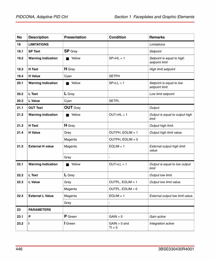
PIDCONA, Adaptive PID Ctrl Section 1 Faceplates and Graphic Elements
19 LIMITATIONS Limitations
19.1 SP Text SP Grey Setpoint
19.2 Warning Indication Yellow SP=HL = 1 Setpoint is equal to high setpoint limit
19.3 H Text H Grey High limit setpoint
19.4 H Value Cyan SETPH
20.1 Warning Indication Yellow SP=LL = 1 Setpoint is equal to low setpoint limit
20.2 L Text L Grey Low limit setpoint
20.3 L Value Cyan SETPL
21.1 OUT Text OUT Grey Output
21.2 Warning Indication Yellow OUT=HL = 1 Output is equal to output high limit
21.3 H Text H Grey Output high limit.
21.4 H Value Grey OUTPH, EOLIM = 1 Output high limit value.
Magenta OUTPH, EOLIM = 0
21.5 External H value Magenta EOLIM = 1 External output high limit value
Grey -
22.1 Warning Indication Yellow OUT=LL = 1 Output is equal to low output limit
22.2 L Text L Grey Output low limit.
22.3 L Value Grey OUTPL, EOLIM = 1 Output low limit value.
Magenta OUTPL, EOLIM = 0
22.4 External L Value Magenta EOLIM = 1 External output low limit value.
Grey -
23 PARAMETERS
23.1 P P Green GAIN > 0 Gain active
23.2 I I Green GAIN > 0 andTI > 0
Integration active
No Description Presentation Condition Remarks
446 3BSE030430R4001
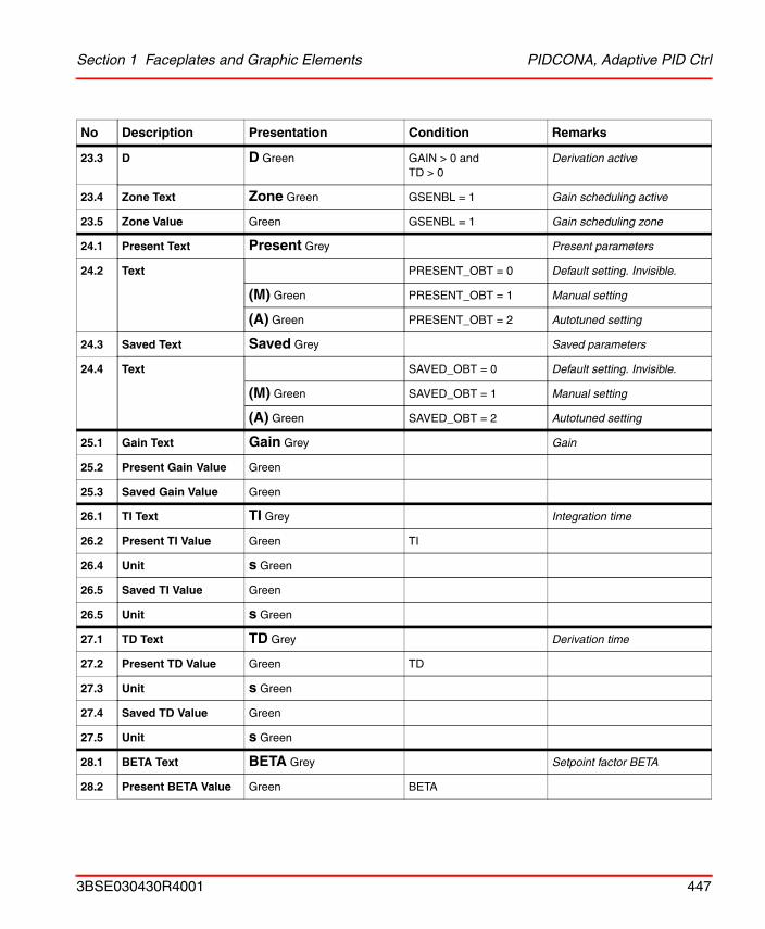
Section 1 Faceplates and Graphic Elements PIDCONA, Adaptive PID Ctrl
23.3 D D Green GAIN > 0 andTD > 0
Derivation active
23.4 Zone Text Zone Green GSENBL = 1 Gain scheduling active
23.5 Zone Value Green GSENBL = 1 Gain scheduling zone
24.1 Present Text Present Grey Present parameters
24.2 Text PRESENT_OBT = 0 Default setting. Invisible.
(M) Green PRESENT_OBT = 1 Manual setting
(A) Green PRESENT_OBT = 2 Autotuned setting
24.3 Saved Text Saved Grey Saved parameters
24.4 Text SAVED_OBT = 0 Default setting. Invisible.
(M) Green SAVED_OBT = 1 Manual setting
(A) Green SAVED_OBT = 2 Autotuned setting
25.1 Gain Text Gain Grey Gain
25.2 Present Gain Value Green
25.3 Saved Gain Value Green
26.1 TI Text TI Grey Integration time
26.2 Present TI Value Green TI
26.4 Unit s Green
26.5 Saved TI Value Green
26.5 Unit s Green
27.1 TD Text TD Grey Derivation time
27.2 Present TD Value Green TD
27.3 Unit s Green
27.4 Saved TD Value Green
27.5 Unit s Green
28.1 BETA Text BETA Grey Setpoint factor BETA
28.2 Present BETA Value Green BETA
No Description Presentation Condition Remarks
3BSE030430R4001 447
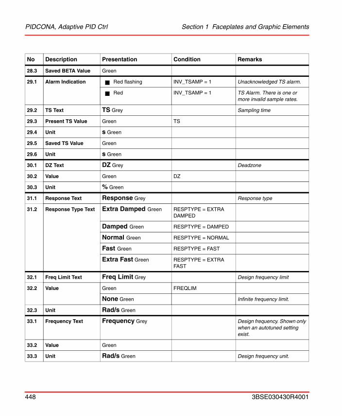
PIDCONA, Adaptive PID Ctrl Section 1 Faceplates and Graphic Elements
28.3 Saved BETA Value Green
29.1 Alarm Indication Red flashing INV_TSAMP = 1 Unacknowledged TS alarm.
Red INV_TSAMP = 1 TS Alarm. There is one or more invalid sample rates.
29.2 TS Text TS Grey Sampling time
29.3 Present TS Value Green TS
29.4 Unit s Green
29.5 Saved TS Value Green
29.6 Unit s Green
30.1 DZ Text DZ Grey Deadzone
30.2 Value Green DZ
30.3 Unit % Green
31.1 Response Text Response Grey Response type
31.2 Response Type Text Extra Damped Green RESPTYPE = EXTRA DAMPED
Damped Green RESPTYPE = DAMPED
Normal Green RESPTYPE = NORMAL
Fast Green RESPTYPE = FAST
Extra Fast Green RESPTYPE = EXTRA FAST
32.1 Freq Limit Text Freq Limit Grey Design frequency limit
32.2 Value Green FREQLIM
None Green Infinite frequency limit.
32.3 Unit Rad/s Green
33.1 Frequency Text Frequency Grey Design frequency. Shown only when an autotuned setting exist.
33.2 Value Green
33.3 Unit Rad/s Green Design frequency unit.
No Description Presentation Condition Remarks
448 3BSE030430R4001
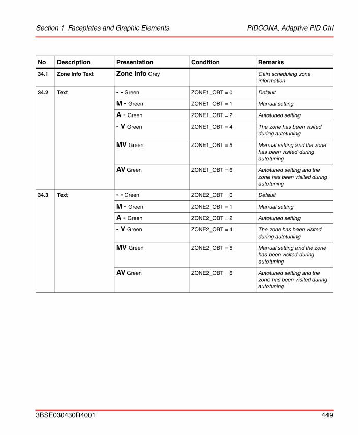
Section 1 Faceplates and Graphic Elements PIDCONA, Adaptive PID Ctrl
34.1 Zone Info Text Zone Info Grey Gain scheduling zone information
34.2 Text - - Green ZONE1_OBT = 0 Default
M - Green ZONE1_OBT = 1 Manual setting
A - Green ZONE1_OBT = 2 Autotuned setting
- V Green ZONE1_OBT = 4 The zone has been visited during autotuning
MV Green ZONE1_OBT = 5 Manual setting and the zone has been visited during autotuning
AV Green ZONE1_OBT = 6 Autotuned setting and the zone has been visited during autotuning
34.3 Text - - Green ZONE2_OBT = 0 Default
M - Green ZONE2_OBT = 1 Manual setting
A - Green ZONE2_OBT = 2 Autotuned setting
- V Green ZONE2_OBT = 4 The zone has been visited during autotuning
MV Green ZONE2_OBT = 5 Manual setting and the zone has been visited during autotuning
AV Green ZONE2_OBT = 6 Autotuned setting and the zone has been visited during autotuning
No Description Presentation Condition Remarks
3BSE030430R4001 449
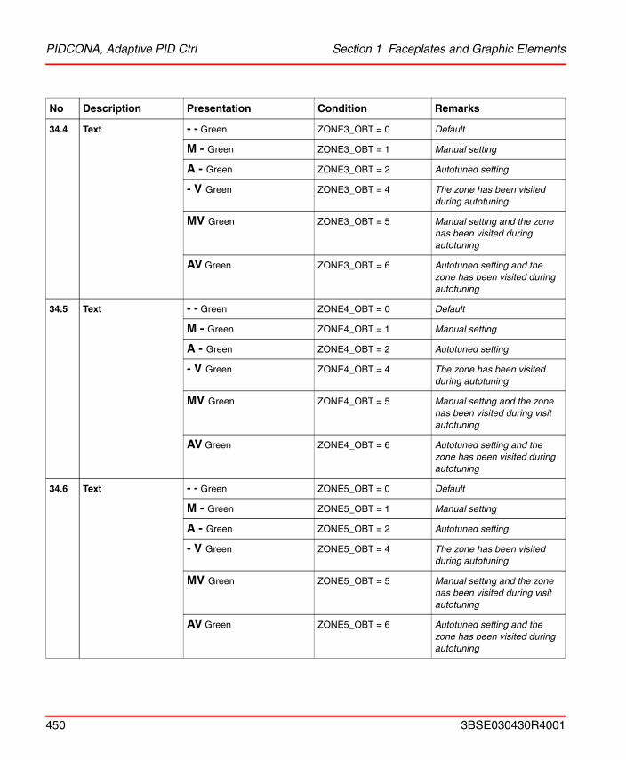
PIDCONA, Adaptive PID Ctrl Section 1 Faceplates and Graphic Elements
34.4 Text - - Green ZONE3_OBT = 0 Default
M - Green ZONE3_OBT = 1 Manual setting
A - Green ZONE3_OBT = 2 Autotuned setting
- V Green ZONE3_OBT = 4 The zone has been visited during autotuning
MV Green ZONE3_OBT = 5 Manual setting and the zone has been visited during autotuning
AV Green ZONE3_OBT = 6 Autotuned setting and the zone has been visited during autotuning
34.5 Text - - Green ZONE4_OBT = 0 Default
M - Green ZONE4_OBT = 1 Manual setting
A - Green ZONE4_OBT = 2 Autotuned setting
- V Green ZONE4_OBT = 4 The zone has been visited during autotuning
MV Green ZONE4_OBT = 5 Manual setting and the zone has been visited during visit autotuning
AV Green ZONE4_OBT = 6 Autotuned setting and the zone has been visited during autotuning
34.6 Text - - Green ZONE5_OBT = 0 Default
M - Green ZONE5_OBT = 1 Manual setting
A - Green ZONE5_OBT = 2 Autotuned setting
- V Green ZONE5_OBT = 4 The zone has been visited during autotuning
MV Green ZONE5_OBT = 5 Manual setting and the zone has been visited during visit autotuning
AV Green ZONE5_OBT = 6 Autotuned setting and the zone has been visited during autotuning
No Description Presentation Condition Remarks
450 3BSE030430R4001
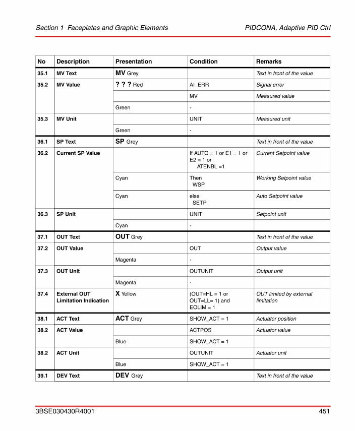
Section 1 Faceplates and Graphic Elements PIDCONA, Adaptive PID Ctrl
35.1 MV Text MV Grey Text in front of the value
35.2 MV Value ? ? ? Red AI_ERR Signal error
MV Measured value
Green -
35.3 MV Unit UNIT Measured unit
Green -
36.1 SP Text SP Grey Text in front of the value
36.2 Current SP Value If AUTO = 1 or E1 = 1 or E2 = 1 or
ATENBL =1
Current Setpoint value
Cyan Then WSP
Working Setpoint value
Cyan elseSETP
Auto Setpoint value
36.3 SP Unit UNIT Setpoint unit
Cyan -
37.1 OUT Text OUT Grey Text in front of the value
37.2 OUT Value OUT Output value
Magenta -
37.3 OUT Unit OUTUNIT Output unit
Magenta -
37.4 External OUT Limitation Indication
X Yellow (OUT=HL = 1 or OUT=LL= 1) and EOLIM = 1
OUT limited by external limitation
38.1 ACT Text ACT Grey SHOW_ACT = 1 Actuator position
38.2 ACT Value ACTPOS Actuator value
Blue SHOW_ACT = 1
38.2 ACT Unit OUTUNIT Actuator unit
Blue SHOW_ACT = 1
39.1 DEV Text DEV Grey Text in front of the value
No Description Presentation Condition Remarks
3BSE030430R4001 451
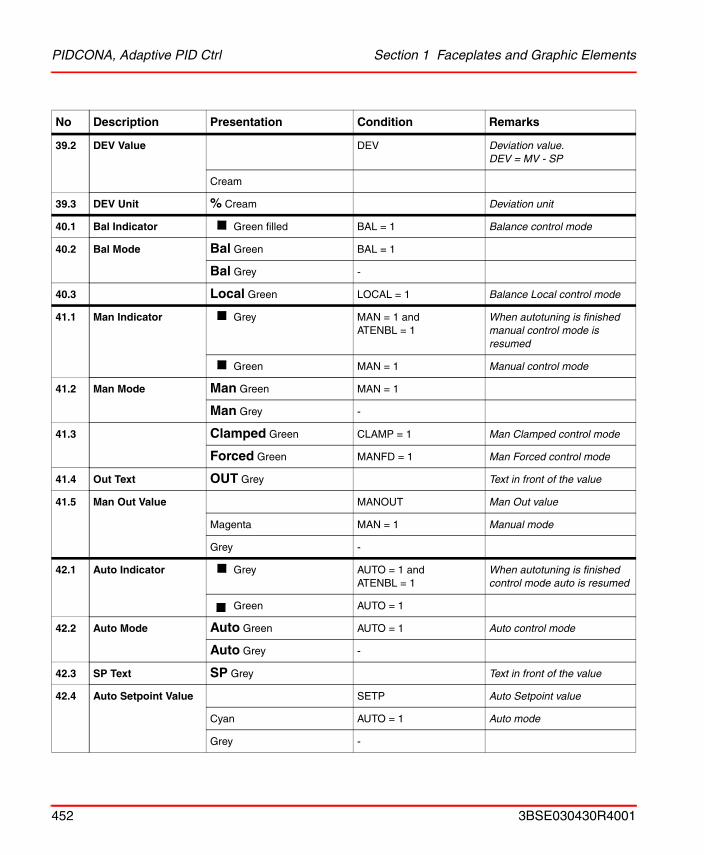
PIDCONA, Adaptive PID Ctrl Section 1 Faceplates and Graphic Elements
39.2 DEV Value DEV Deviation value.DEV = MV - SP
Cream
39.3 DEV Unit % Cream Deviation unit
40.1 Bal Indicator Green filled BAL = 1 Balance control mode
40.2 Bal Mode Bal Green BAL = 1
Bal Grey -
40.3 Local Green LOCAL = 1 Balance Local control mode
41.1 Man Indicator Grey MAN = 1 andATENBL = 1
When autotuning is finished manual control mode is resumed
Green MAN = 1 Manual control mode
41.2 Man Mode Man Green MAN = 1
Man Grey -
41.3 Clamped Green CLAMP = 1 Man Clamped control mode
Forced Green MANFD = 1 Man Forced control mode
41.4 Out Text OUT Grey Text in front of the value
41.5 Man Out Value MANOUT Man Out value
Magenta MAN = 1 Manual mode
Grey -
42.1 Auto Indicator Grey AUTO = 1 andATENBL = 1
When autotuning is finished control mode auto is resumed
Green AUTO = 1
42.2 Auto Mode Auto Green AUTO = 1 Auto control mode
Auto Grey -
42.3 SP Text SP Grey Text in front of the value
42.4 Auto Setpoint Value SETP Auto Setpoint value
Cyan AUTO = 1 Auto mode
Grey -
No Description Presentation Condition Remarks
452 3BSE030430R4001
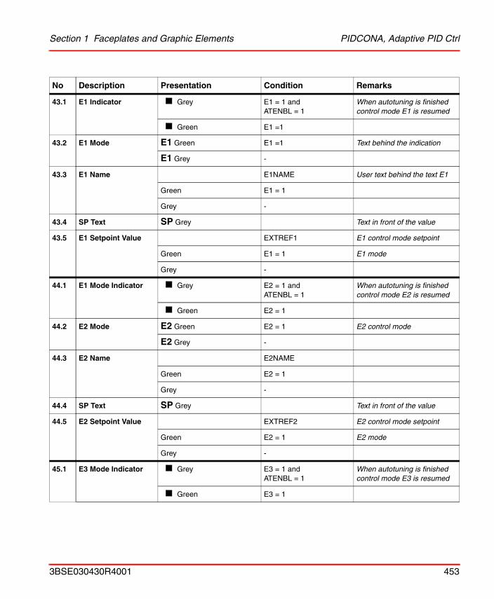
Section 1 Faceplates and Graphic Elements PIDCONA, Adaptive PID Ctrl
43.1 E1 Indicator Grey E1 = 1 andATENBL = 1
When autotuning is finished control mode E1 is resumed
Green E1 =1
43.2 E1 Mode E1 Green E1 =1 Text behind the indication
E1 Grey -
43.3 E1 Name E1NAME User text behind the text E1
Green E1 = 1
Grey -
43.4 SP Text SP Grey Text in front of the value
43.5 E1 Setpoint Value EXTREF1 E1 control mode setpoint
Green E1 = 1 E1 mode
Grey -
44.1 E1 Mode Indicator Grey E2 = 1 andATENBL = 1
When autotuning is finished control mode E2 is resumed
Green E2 = 1
44.2 E2 Mode E2 Green E2 = 1 E2 control mode
E2 Grey -
44.3 E2 Name E2NAME
Green E2 = 1
Grey -
44.4 SP Text SP Grey Text in front of the value
44.5 E2 Setpoint Value EXTREF2 E2 control mode setpoint
Green E2 = 1 E2 mode
Grey -
45.1 E3 Mode Indicator Grey E3 = 1 andATENBL = 1
When autotuning is finished control mode E3 is resumed
Green E3 = 1
No Description Presentation Condition Remarks
3BSE030430R4001 453
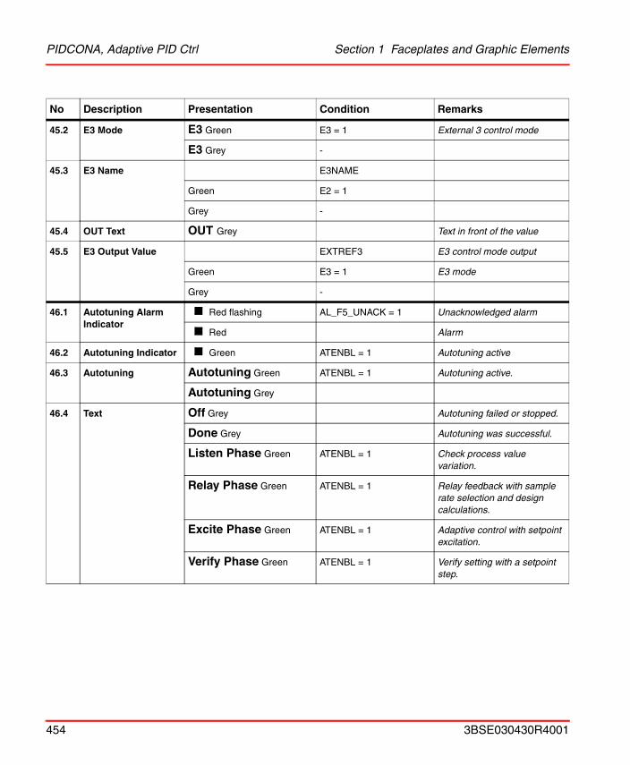
PIDCONA, Adaptive PID Ctrl Section 1 Faceplates and Graphic Elements
45.2 E3 Mode E3 Green E3 = 1 External 3 control mode
E3 Grey -
45.3 E3 Name E3NAME
Green E2 = 1
Grey -
45.4 OUT Text OUT Grey Text in front of the value
45.5 E3 Output Value EXTREF3 E3 control mode output
Green E3 = 1 E3 mode
Grey -
46.1 Autotuning AlarmIndicator
Red flashing AL_F5_UNACK = 1 Unacknowledged alarm
Red Alarm
46.2 Autotuning Indicator Green ATENBL = 1 Autotuning active
46.3 Autotuning Autotuning Green ATENBL = 1 Autotuning active.
Autotuning Grey
46.4 Text Off Grey Autotuning failed or stopped.
Done Grey Autotuning was successful.
Listen Phase Green ATENBL = 1 Check process value variation.
Relay Phase Green ATENBL = 1 Relay feedback with sample rate selection and design calculations.
Excite Phase Green ATENBL = 1 Adaptive control with setpoint excitation.
Verify Phase Green ATENBL = 1 Verify setting with a setpoint step.
No Description Presentation Condition Remarks
454 3BSE030430R4001
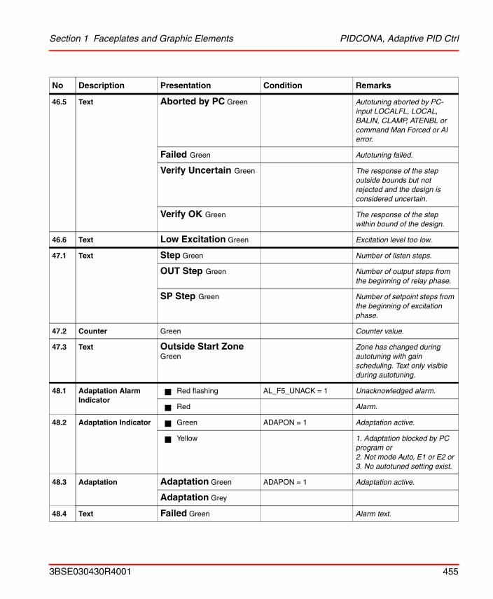
Section 1 Faceplates and Graphic Elements PIDCONA, Adaptive PID Ctrl
46.5 Text Aborted by PC Green Autotuning aborted by PC-input LOCALFL, LOCAL, BALIN, CLAMP, ATENBL or command Man Forced or AI error.
Failed Green Autotuning failed.
Verify Uncertain Green The response of the step outside bounds but not rejected and the design is considered uncertain.
Verify OK Green The response of the step within bound of the design.
46.6 Text Low Excitation Green Excitation level too low.
47.1 Text Step Green Number of listen steps.
OUT Step Green Number of output steps from the beginning of relay phase.
SP Step Green Number of setpoint steps from the beginning of excitation phase.
47.2 Counter Green Counter value.
47.3 Text Outside Start ZoneGreen
Zone has changed during autotuning with gain scheduling. Text only visible during autotuning.
48.1 Adaptation AlarmIndicator
Red flashing AL_F5_UNACK = 1 Unacknowledged alarm.
Red Alarm.
48.2 Adaptation Indicator Green ADAPON = 1 Adaptation active.
Yellow 1. Adaptation blocked by PC program or2. Not mode Auto, E1 or E2 or 3. No autotuned setting exist.
48.3 Adaptation Adaptation Green ADAPON = 1 Adaptation active.
Adaptation Grey
48.4 Text Failed Green Alarm text.
No Description Presentation Condition Remarks
3BSE030430R4001 455
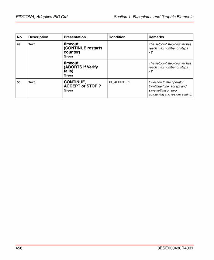
PIDCONA, Adaptive PID Ctrl Section 1 Faceplates and Graphic Elements
49 Text timeout (CONTINUE restarts counter)Green
The setpoint step counter has reach max number of steps- 2.
timeout (ABORTS if Verify fails)Green
The setpoint step counter has reach max number of steps- 2.
50 Text CONTINUE, ACCEPT or STOP ?Green
AT_ALERT = 1 Question to the operator. Continue tune, accept and save setting or stop autotuning and restore setting.
No Description Presentation Condition Remarks
456 3BSE030430R4001
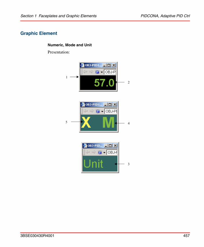
Section 1 Faceplates and Graphic Elements PIDCONA, Adaptive PID Ctrl
Graphic Element
Numeric, Mode and Unit
Presentation:
12
45
3
3BSE030430R4001 457
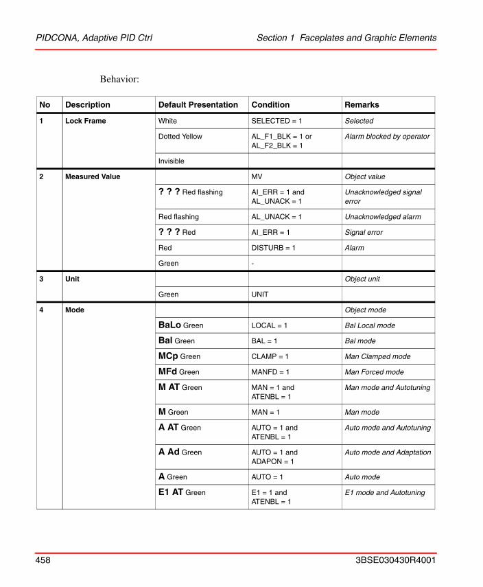
PIDCONA, Adaptive PID Ctrl Section 1 Faceplates and Graphic Elements
Behavior:
No Description Default Presentation Condition Remarks
1 Lock Frame White SELECTED = 1 Selected
Dotted Yellow AL_F1_BLK = 1 orAL_F2_BLK = 1
Alarm blocked by operator
Invisible
2 Measured Value MV Object value
? ? ? Red flashing AI_ERR = 1 and AL_UNACK = 1
Unacknowledged signal error
Red flashing AL_UNACK = 1 Unacknowledged alarm
? ? ? Red AI_ERR = 1 Signal error
Red DISTURB = 1 Alarm
Green -
3 Unit Object unit
Green UNIT
4 Mode Object mode
BaLo Green LOCAL = 1 Bal Local mode
Bal Green BAL = 1 Bal mode
MCp Green CLAMP = 1 Man Clamped mode
MFd Green MANFD = 1 Man Forced mode
M AT Green MAN = 1 andATENBL = 1
Man mode and Autotuning
M Green MAN = 1 Man mode
A AT Green AUTO = 1 andATENBL = 1
Auto mode and Autotuning
A Ad Green AUTO = 1 andADAPON = 1
Auto mode and Adaptation
A Green AUTO = 1 Auto mode
E1 AT Green E1 = 1 andATENBL = 1
E1 mode and Autotuning
458 3BSE030430R4001
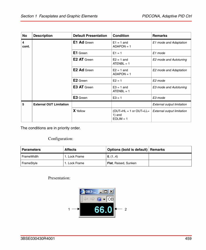
Section 1 Faceplates and Graphic Elements PIDCONA, Adaptive PID Ctrl
The conditions are in priority order.
Configuration:
Presentation:
4 cont.
E1 Ad Green E1 = 1 andADAPON = 1
E1 mode and Adaptation
E1 Green E1 = 1 E1 mode
E2 AT Green E2 = 1 andATENBL = 1
E2 mode and Autotuning
E2 Ad Green E2 = 1 andADAPON = 1
E2 mode and Adaptation
E2 Green E2 = 1 E2 mode
E3 AT Green E3 = 1 andATENBL = 1
E3 mode and Autotuning
E3 Green E3 = 1 E3 mode
5 External OUT Limitation External output limitation
X Yellow (OUT=HL = 1 or OUT=LL= 1) and EOLIM = 1
External output limitation
Parameters Affects Options (bold is default) Remarks
FrameWidth 1. Lock Frame 0, (1..4)
FrameStyle 1. Lock Frame Flat, Raised, Sunken
No Description Default Presentation Condition Remarks
21
3BSE030430R4001 459
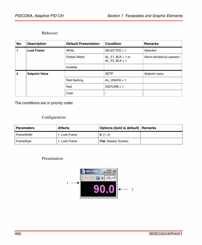
PIDCONA, Adaptive PID Ctrl Section 1 Faceplates and Graphic Elements
Behavior:
The conditions are in priority order.
Configuration:
Presentation:
No Description Default Presentation Condition Remarks
1 Lock Frame White SELECTED = 1 Selected
Dotted Yellow AL_F1_BLK = 1 orAL_F2_BLK = 1
Alarm blocked by operator
Invisible
2 Setpoint Value SETP Setpoint value
Red flashing AL_UNACK = 1
Red DISTURB = 1
Cyan -
Parameters Affects Options (bold is default) Remarks
FrameWidth 1. Lock Frame 0, (1..4)
FrameStyle 1. Lock Frame Flat, Raised, Sunken
1
2
460 3BSE030430R4001
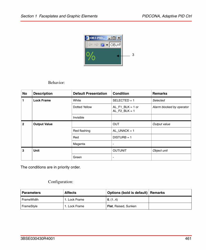
Section 1 Faceplates and Graphic Elements PIDCONA, Adaptive PID Ctrl
Behavior:
The conditions are in priority order.
Configuration:
No Description Default Presentation Condition Remarks
1 Lock Frame White SELECTED = 1 Selected
Dotted Yellow AL_F1_BLK = 1 orAL_F2_BLK = 1
Alarm blocked by operator
Invisible
2 Output Value OUT Output value
Red flashing AL_UNACK = 1
Red DISTURB = 1
Magenta -
3 Unit OUTUNIT Object unit
Green -
Parameters Affects Options (bold is default) Remarks
FrameWidth 1. Lock Frame 0, (1..4)
FrameStyle 1. Lock Frame Flat, Raised, Sunken
3
3BSE030430R4001 461
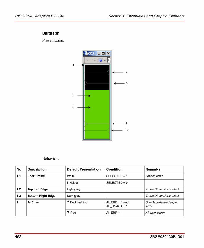
PIDCONA, Adaptive PID Ctrl Section 1 Faceplates and Graphic Elements
Bargraph
Presentation:
Behavior:
No Description Default Presentation Condition Remarks
1.1 Lock Frame White SELECTED = 1 Object frame
Invisible SELECTED = 0
1.2 Top Left Edge Light grey Three Dimensions effect
1.3 Bottom Right Edge Dark grey Three Dimensions effect
2 AI Error ? Red flashing AI_ERR = 1 and AL_UNACK = 1
Unacknowledged signal error
? Red AI_ERR = 1 AI error alarm
1
2
3
4
5
6
7
462 3BSE030430R4001
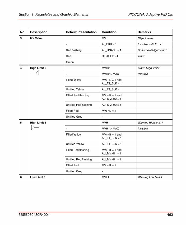
Section 1 Faceplates and Graphic Elements PIDCONA, Adaptive PID Ctrl
3 MV Value MV Object value
- AI_ERR = 1 Invisible - I/O Error
Red flashing AL_UNACK = 1 Unacknowledged alarm
Red DISTURB =1 Alarm
Green -
4 High Limit 2 MVH2 Alarm High limit 2
- MVH2 > MAX Invisible
Filled Yellow MV>H2 = 1 and AL_F2_BLK = 1
Unfilled Yellow AL_F2_BLK = 1
Filled Red flashing MV>H2 = 1 and AU_MV>H2 = 1
Unfilled Red flashing AU_MV>H2 = 1
Filled Red MV>H2 = 1
Unfilled Grey -
5 High Limit 1 MVH1 Warning High limit 1
- MVH1 > MAX Invisible
Filled Yellow MV>H1 = 1 and AL_F1_BLK = 1
Unfilled Yellow AL_F1_BLK = 1
Filled Red flashing MV>H1 = 1 and AU_MV>H1 = 1
Unfilled Red flashing AU_MV>H1 = 1
Filled Red MV>H1 = 1
Unfilled Grey -
6 Low Limit 1 MVL1 Warning Low limit 1
No Description Default Presentation Condition Remarks
3BSE030430R4001 463
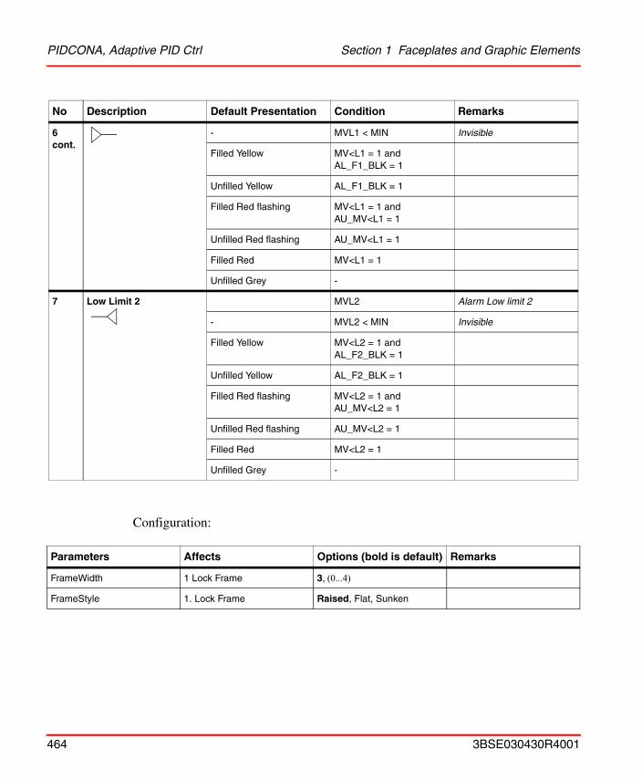
PIDCONA, Adaptive PID Ctrl Section 1 Faceplates and Graphic Elements
Configuration:
6 cont.
- MVL1 < MIN Invisible
Filled Yellow MV<L1 = 1 and AL_F1_BLK = 1
Unfilled Yellow AL_F1_BLK = 1
Filled Red flashing MV<L1 = 1 and AU_MV<L1 = 1
Unfilled Red flashing AU_MV<L1 = 1
Filled Red MV<L1 = 1
Unfilled Grey -
7 Low Limit 2 MVL2 Alarm Low limit 2
- MVL2 < MIN Invisible
Filled Yellow MV<L2 = 1 and AL_F2_BLK = 1
Unfilled Yellow AL_F2_BLK = 1
Filled Red flashing MV<L2 = 1 and AU_MV<L2 = 1
Unfilled Red flashing AU_MV<L2 = 1
Filled Red MV<L2 = 1
Unfilled Grey -
Parameters Affects Options (bold is default) Remarks
FrameWidth 1 Lock Frame 3, (0...4)
FrameStyle 1. Lock Frame Raised, Flat, Sunken
No Description Default Presentation Condition Remarks
464 3BSE030430R4001
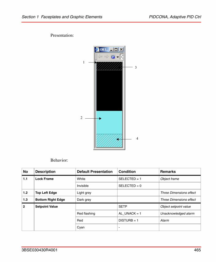
Section 1 Faceplates and Graphic Elements PIDCONA, Adaptive PID Ctrl
Presentation:
Behavior:
No Description Default Presentation Condition Remarks
1.1 Lock Frame White SELECTED = 1 Object frame
Invisible SELECTED = 0
1.2 Top Left Edge Light grey Three Dimensions effect
1.3 Bottom Right Edge Dark grey Three Dimensions effect
2 Setpoint Value SETP Object setpoint value
Red flashing AL_UNACK = 1 Unacknowledged alarm
Red DISTURB = 1 Alarm
Cyan -
3
4
1
2
3BSE030430R4001 465
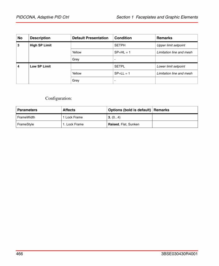
PIDCONA, Adaptive PID Ctrl Section 1 Faceplates and Graphic Elements
Configuration:
3 High SP Limit SETPH Upper limit setpoint
Yellow SP=HL = 1 Limitation line and mesh
Grey -
4 Low SP Limit SETPL Lower limit setpoint
Yellow SP=LL = 1 Limitation line and mesh
Grey -
Parameters Affects Options (bold is default) Remarks
FrameWidth 1 Lock Frame 3, (0...4)
FrameStyle 1. Lock Frame Raised, Flat, Sunken
No Description Default Presentation Condition Remarks
466 3BSE030430R4001
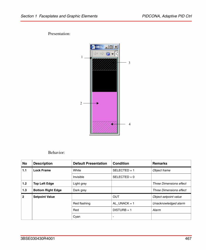
Section 1 Faceplates and Graphic Elements PIDCONA, Adaptive PID Ctrl
Presentation:
Behavior:
No Description Default Presentation Condition Remarks
1.1 Lock Frame White SELECTED = 1 Object frame
Invisible SELECTED = 0
1.2 Top Left Edge Light grey Three Dimensions effect
1.3 Bottom Right Edge Dark grey Three Dimensions effect
2 Setpoint Value OUT Object setpoint value
Red flashing AL_UNACK = 1 Unacknowledged alarm
Red DISTURB = 1 Alarm
Cyan -
3
4
1
2
3BSE030430R4001 467
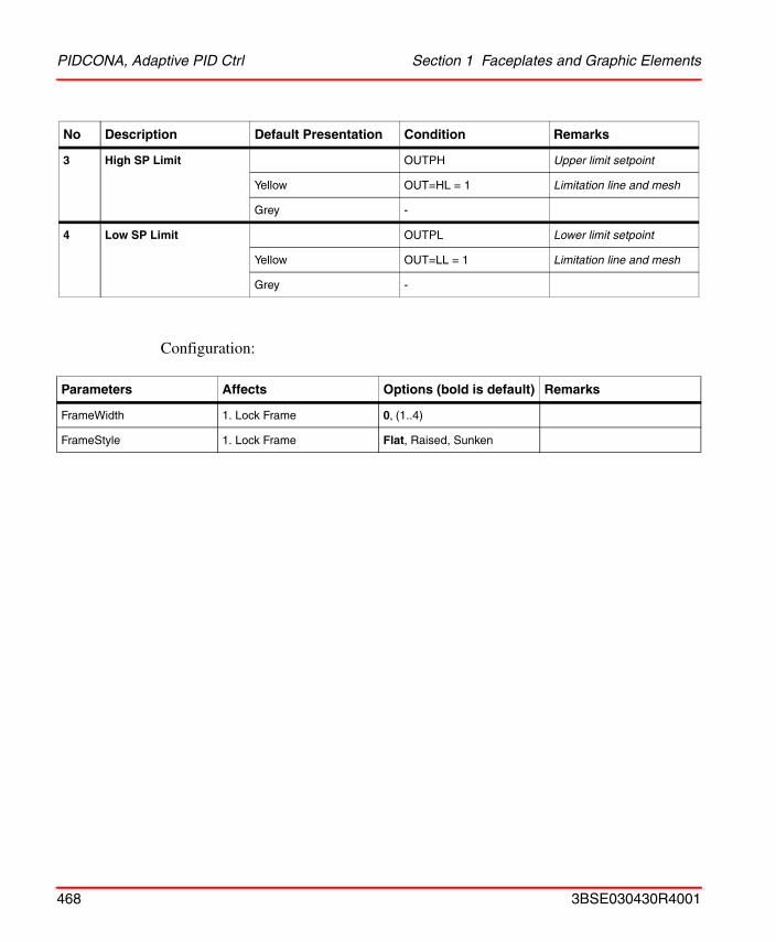
PIDCONA, Adaptive PID Ctrl Section 1 Faceplates and Graphic Elements
Configuration:
3 High SP Limit OUTPH Upper limit setpoint
Yellow OUT=HL = 1 Limitation line and mesh
Grey -
4 Low SP Limit OUTPL Lower limit setpoint
Yellow OUT=LL = 1 Limitation line and mesh
Grey -
Parameters Affects Options (bold is default) Remarks
FrameWidth 1. Lock Frame 0, (1..4)
FrameStyle 1. Lock Frame Flat, Raised, Sunken
No Description Default Presentation Condition Remarks
468 3BSE030430R4001
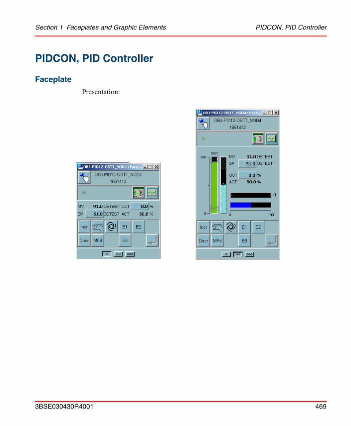
Section 1 Faceplates and Graphic Elements PIDCON, PID Controller
PIDCON, PID Controller
Faceplate
Presentation:
3BSE030430R4001 469
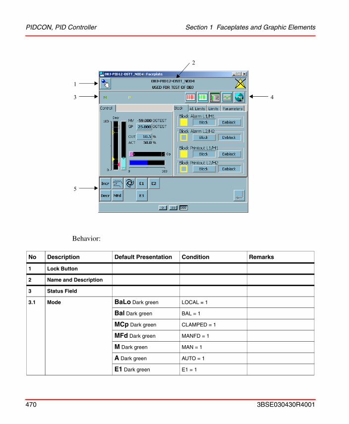
PIDCON, PID Controller Section 1 Faceplates and Graphic Elements
Behavior:
No Description Default Presentation Condition Remarks
1 Lock Button
2 Name and Description
3 Status Field
3.1 Mode BaLo Dark green LOCAL = 1
Bal Dark green BAL = 1
MCp Dark green CLAMPED = 1
MFd Dark green MANFD = 1
M Dark green MAN = 1
A Dark green AUTO = 1
E1 Dark green E1 = 1
1
3
5
4
2
470 3BSE030430R4001
Section 1 Faceplates and Graphic Elements PIDCON, PID Controller
3.1 cont.
E2 Dark green E2 = 1
E3 Dark green E3 = 1
3.2 Print Blk P Yellow PRINT_F1_BLK = 1 or PRINT_F2_BLK = 1
4 Aspect links Alarm List position 0, 0, 8
Event List position 0, 0, 9
Object Display position 5, 5, 10
Trend Display position 6, 6, 11
Object Type Help position 0, 0 , 12
5 Incr Increase outputwith 0,5 unit
MAN = 1
Increase setpointwith 0,5 unit
AUTO = 1
Decr Decrease output with 0,5 unit
MAN = 1
Decrease setpoint with 0,5 unit
AUTO = 1
Man Set to Man Mode Set MMI_MAN = 1
Auto Set to Auto Mode Set MMI_AUTO = 1
MFd Set to Man Force Mode Set MANFD = 1
E1 Set to E1 Mode Set MMI_E1 = 1
E2 Set to E2 Mode Set MMI_E2 = 1
E3 Set to E3 Mode Set MMI_E3 = 1
No Description Default Presentation Condition Remarks
3BSE030430R4001 471
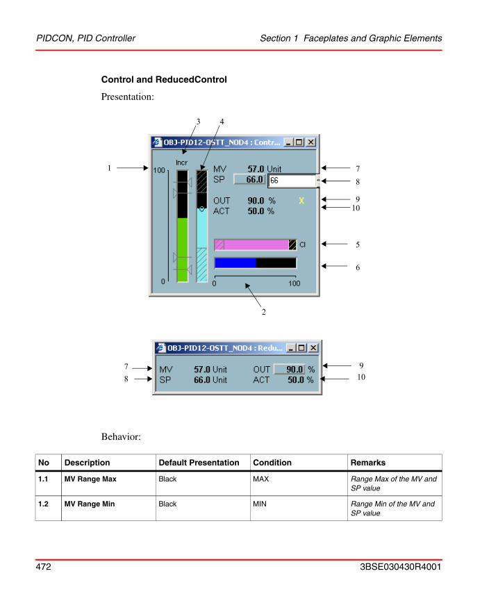
PIDCON, PID Controller Section 1 Faceplates and Graphic Elements
Control and ReducedControl
Presentation:
Behavior:
No Description Default Presentation Condition Remarks
1.1 MV Range Max Black MAX Range Max of the MV and SP value
1.2 MV Range Min Black MIN Range Min of the MV and SP value
8
9
7
6
1
3 4
10
5
2
910
78
472 3BSE030430R4001
Section 1 Faceplates and Graphic Elements PIDCON, PID Controller
2.1 OUT Range Max 100.0 Black Range Max of OUT is 100.0%
2.2 OUT Range Min 0.0 Black Range Min of OUT is 0.0%
3.1 Direction Incr Green MV_DIR = INCREASING Increase of measured value
Decr Green MV_DIR = DECREASING Decrease of measured value
3.2 Measured Value Bargraph
MV Measured Value
Green -
3.3 High Limit 2 MVH2 Alarm High limit 2
- MVH2 >= MAX Invisible
Filled Yellow MV>H2 = 1 and AL_F2_BLK = 1
Unfilled Yellow AL_F2_BLK = 1
Filled Red flashing MV>H2 = 1 and AU_MV>H2 = 1
Unfilled Red flashing AU_MV>H2 = 1
Filled Red MV>H2 = 1
Unfilled Grey -
3.4 High Limit 1 MVH1 Warning High limit 1
- MVH1 >= MAX Invisible
Filled Yellow MV>H1 = 1 and AL_F1_BLK = 1
Unfilled Yellow AL_F1_BLK = 1
Filled Red flashing MV>H1 = 1 and AU_MV>H1 = 1
Unfilled Red flashing AU_MV>H1 = 1
Filled Red MV>H1 = 1
Unfilled Grey -
3.5 Low Limit 1 MVL1 Warning Low limit 1
No Description Default Presentation Condition Remarks
3BSE030430R4001 473
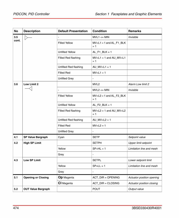
PIDCON, PID Controller Section 1 Faceplates and Graphic Elements
3.5 cont.
- MVL1 <= MIN Invisible
Filled Yellow MV<L1 = 1 and AL_F1_BLK = 1
Unfilled Yellow AL_F1_BLK = 1
Filled Red flashing MV<L1 = 1 and AU_MV<L1 = 1
Unfilled Red flashing AU_MV<L1 = 1
Filled Red MV<L1 = 1
Unfilled Grey -
3.6 Low Limit 2 MVL2 Alarm Low limit 2
- MVL2 <= MIN Invisible
Filled Yellow MV<L2 = 1 and AL_F2_BLK = 1
Unfilled Yellow AL_F2_BLK = 1
Filled Red flashing MV<L2 = 1 and AU_MV<L2 = 1
Unfilled Red flashing AU_MV<L2 = 1
Filled Red MV<L2 = 1
Unfilled Grey -
4.1 SP Value Bargraph Cyan SETP Setpoint value
4.2 High SP Limit SETPH Upper limit setpoint
Yellow SP=HL = 1 Limitation line and mesh
Grey -
4.3 Low SP Limit SETPL Lower setpoint limit
Yellow SP=LL = 1 Limitation line and mesh
Grey -
5.1 Opening or Closing Op Magenta ACT_DIR = OPENING Actuator position opening
Cl Magenta ACT_DIR = CLOSING Actuator position closing
5.2 OUT Value Bargraph POUT Output value
No Description Default Presentation Condition Remarks
474 3BSE030430R4001
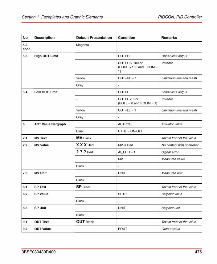
Section 1 Faceplates and Graphic Elements PIDCON, PID Controller
5.2 cont.
Magenta -
5.3 HIgh OUT Limit OUTPH Upper limit output
- OUTPH > 100 or(EOHL > 100 and EOLIM = 1)
Invisible
Yellow OUT=HL = 1 Limitation line and mesh
Grey -
5.4 Low OUT Limit OUTPL Lower limit output
- OUTPL < 0 or(EOLL < 0 and EOLIM = 1)
Invisible
Yellow OUT=LL = 1 Limitation line and mesh
Grey -
6 ACT Value Bargraph ACTPOS Actuator value
Blue CTRL = ON-OFF
7.1 MV Text MV Black Text in front of the value
7.2 MV Value X X X Red MV is Bad No contact with controller
? ? ? Red AI_ERR = 1 Signal error
MV Measured value
Black -
7.3 MV Unit UNIT Measured unit
Black -
8.1 SP Text SP Black Text in front of the value
8.2 SP Value SETP Setpoint value
Black -
8.3 SP Unit UNIT Setpoint unit
Black -
9.1 OUT Text OUT Black Text in front of the value
9.2 OUT Value POUT Output value
No Description Default Presentation Condition Remarks
3BSE030430R4001 475
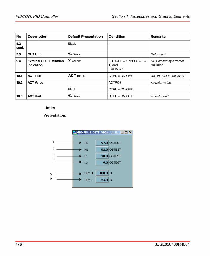
PIDCON, PID Controller Section 1 Faceplates and Graphic Elements
Limits
Presentation:
9.2 cont.
Black -
9.3 OUT Unit % Black Output unit
9.4 External OUT Limitation Indication
X Yellow (OUT=HL = 1 or OUT=LL= 1) and EOLIM = 1
OUT limited by external limitation
10.1 ACT Text ACT Black CTRL = ON-OFF Text in front of the value
10.2 ACT Value ACTPOS Actuator value
Black CTRL = ON-OFF
10.3 ACT Unit % Black CTRL = ON-OFF Actuator unit
No Description Default Presentation Condition Remarks
1
2
3
56
4
476 3BSE030430R4001
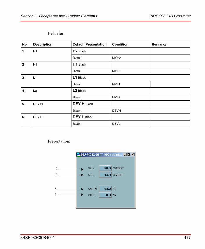
Section 1 Faceplates and Graphic Elements PIDCON, PID Controller
Behavior:
Presentation:
No Description Default Presentation Condition Remarks
1 H2 H2 Black
Black MVH2
2 H1 H1 Black
Black MVH1
3 L1 L1 Black
Black MVL1
4 L2 L2 Black
Black MVL2
5 DEV H DEV H Black
Black DEVH
6 DEV L DEV L Black
Black DEVL
12
4
3
3BSE030430R4001 477
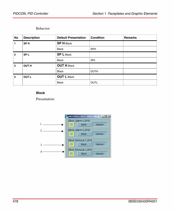
PIDCON, PID Controller Section 1 Faceplates and Graphic Elements
Behavior:
Block
Presentation:
No Description Default Presentation Condition Remarks
1 SP H SP H Black
Black SPH
2 SP L SP L Black
Black SPL
3 OUT H OUT H Black
Black OUTH
4 OUT L OUT L Black
Black OUTL
1
2
3
4
478 3BSE030430R4001
Section 1 Faceplates and Graphic Elements PIDCON, PID Controller
Behavior:
No Description Default Presentation Condition Remarks
1 Block Alarm 1 Block Alarm L1/H1 Black
! Yellow Blocked
Block pressed AL_F1_BLK = 1
Deblock pressed AL_F1_BLK = 0
2 Block Alarm 2 Block Alarm L2/H2 Black
! Yellow Blocked
Block pressed AL_F2_BLK = 1
Deblock pressed AL_F2_BLK= 0
3 Block Printout 1 Block Printout L1/H1 Black
! Yellow Blocked
Block pressed PRINT_F1_BLK = 1
Deblock pressed PRINT_F1_BLK = 0
4 Block Printout 2 Block Printout L2/H2 Black
! Yellow Blocked
Block pressed PRINT_F2_BLK = 1
Deblock pressed PRINT_F2_BLK = 0
3BSE030430R4001 479
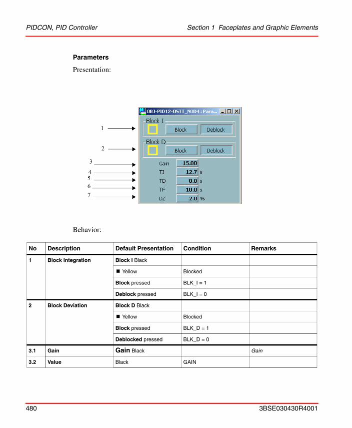
PIDCON, PID Controller Section 1 Faceplates and Graphic Elements
Parameters
Presentation:
Behavior:
No Description Default Presentation Condition Remarks
1 Block Integration Block I Black
! Yellow Blocked
Block pressed BLK_I = 1
Deblock pressed BLK_I = 0
2 Block Deviation Block D Black
! Yellow Blocked
Block pressed BLK_D = 1
Deblocked pressed BLK_D = 0
3.1 Gain Gain Black Gain
3.2 Value Black GAIN
4
3
67
5
1
2
480 3BSE030430R4001
Section 1 Faceplates and Graphic Elements PIDCON, PID Controller
4.1 TI TI Black Integration time
4.2 Value Black TI
4.3 Unit s Black
5.1 TD TD Black Derivation time
5.2 Value Black TD
5.3 Unit s Black
6.1 TF TF Black Filter Time
6.2 Value Black TF
6.3 Unit s Black
7.1 DZ DZ Black Dead zone
7.2 Value Black DZ, CTRL = ON - OFF
7.3 Unit % Black DZ, CTRL = ON - OFF
No Description Default Presentation Condition Remarks
3BSE030430R4001 481
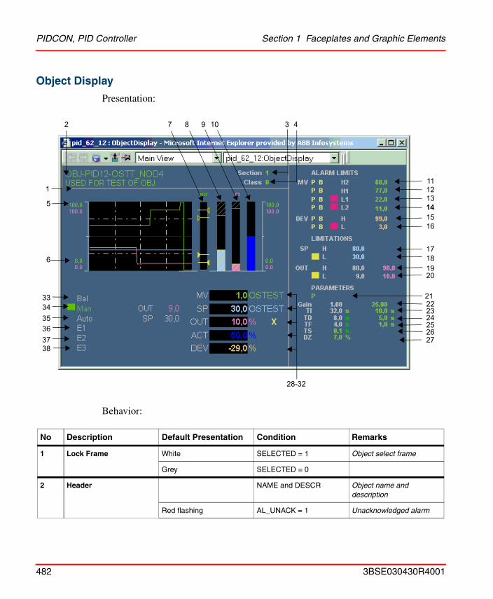
PIDCON, PID Controller Section 1 Faceplates and Graphic Elements
Object Display
Presentation:
Behavior:
No Description Default Presentation Condition Remarks
1 Lock Frame White SELECTED = 1 Object select frame
Grey SELECTED = 0
2 Header NAME and DESCR Object name and description
Red flashing AL_UNACK = 1 Unacknowledged alarm
11
3 42
121314
1718
7 8 9
1
1516
1920
25242322
10
2627
5
6
333435363738
28-32
14
21
482 3BSE030430R4001
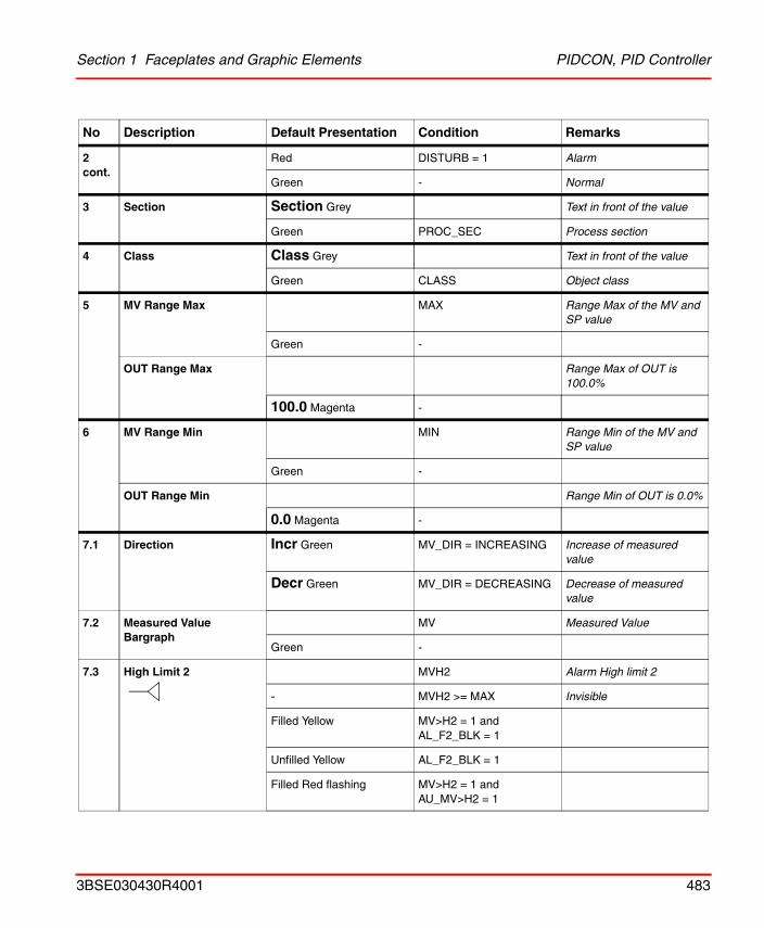
Section 1 Faceplates and Graphic Elements PIDCON, PID Controller
2 cont.
Red DISTURB = 1 Alarm
Green - Normal
3 Section Section Grey Text in front of the value
Green PROC_SEC Process section
4 Class Class Grey Text in front of the value
Green CLASS Object class
5 MV Range Max MAX Range Max of the MV and SP value
Green -
OUT Range Max Range Max of OUT is 100.0%
100.0 Magenta -
6 MV Range Min MIN Range Min of the MV and SP value
Green -
OUT Range Min Range Min of OUT is 0.0%
0.0 Magenta -
7.1 Direction Incr Green MV_DIR = INCREASING Increase of measured value
Decr Green MV_DIR = DECREASING Decrease of measured value
7.2 Measured Value Bargraph
MV Measured Value
Green -
7.3 High Limit 2 MVH2 Alarm High limit 2
- MVH2 >= MAX Invisible
Filled Yellow MV>H2 = 1 and AL_F2_BLK = 1
Unfilled Yellow AL_F2_BLK = 1
Filled Red flashing MV>H2 = 1 and AU_MV>H2 = 1
No Description Default Presentation Condition Remarks
3BSE030430R4001 483
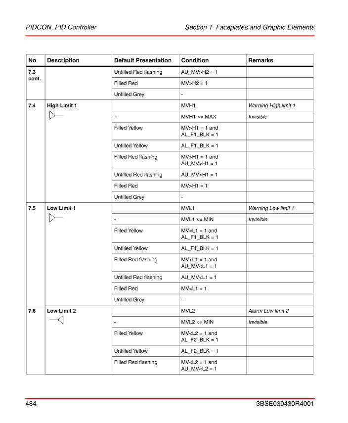
PIDCON, PID Controller Section 1 Faceplates and Graphic Elements
7.3 cont.
Unfilled Red flashing AU_MV>H2 = 1
Filled Red MV>H2 = 1
Unfilled Grey -
7.4 High Limit 1 MVH1 Warning High limit 1
- MVH1 >= MAX Invisible
Filled Yellow MV>H1 = 1 and AL_F1_BLK = 1
Unfilled Yellow AL_F1_BLK = 1
Filled Red flashing MV>H1 = 1 and AU_MV>H1 = 1
Unfilled Red flashing AU_MV>H1 = 1
Filled Red MV>H1 = 1
Unfilled Grey -
7.5 Low Limit 1 MVL1 Warning Low limit 1
- MVL1 <= MIN Invisible
Filled Yellow MV<L1 = 1 and AL_F1_BLK = 1
Unfilled Yellow AL_F1_BLK = 1
Filled Red flashing MV<L1 = 1 and AU_MV<L1 = 1
Unfilled Red flashing AU_MV<L1 = 1
Filled Red MV<L1 = 1
Unfilled Grey -
7.6 Low Limit 2 MVL2 Alarm Low limit 2
- MVL2 <= MIN Invisible
Filled Yellow MV<L2 = 1 and AL_F2_BLK = 1
Unfilled Yellow AL_F2_BLK = 1
Filled Red flashing MV<L2 = 1 and AU_MV<L2 = 1
No Description Default Presentation Condition Remarks
484 3BSE030430R4001
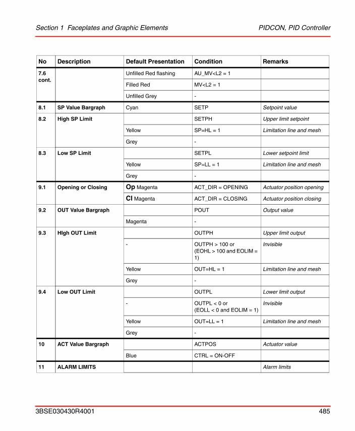
Section 1 Faceplates and Graphic Elements PIDCON, PID Controller
7.6 cont.
Unfilled Red flashing AU_MV<L2 = 1
Filled Red MV<L2 = 1
Unfilled Grey -
8.1 SP Value Bargraph Cyan SETP Setpoint value
8.2 High SP Limit SETPH Upper limit setpoint
Yellow SP=HL = 1 Limitation line and mesh
Grey -
8.3 Low SP Limit SETPL Lower setpoint limit
Yellow SP=LL = 1 Limitation line and mesh
Grey -
9.1 Opening or Closing Op Magenta ACT_DIR = OPENING Actuator position opening
Cl Magenta ACT_DIR = CLOSING Actuator position closing
9.2 OUT Value Bargraph POUT Output value
Magenta -
9.3 HIgh OUT Limit OUTPH Upper limit output
- OUTPH > 100 or(EOHL > 100 and EOLIM = 1)
Invisible
Yellow OUT=HL = 1 Limitation line and mesh
Grey -
9.4 Low OUT Limit OUTPL Lower limit output
- OUTPL < 0 or(EOLL < 0 and EOLIM = 1)
Invisible
Yellow OUT=LL = 1 Limitation line and mesh
Grey -
10 ACT Value Bargraph ACTPOS Actuator value
Blue CTRL = ON-OFF
11 ALARM LIMITS Alarm limits
No Description Default Presentation Condition Remarks
3BSE030430R4001 485
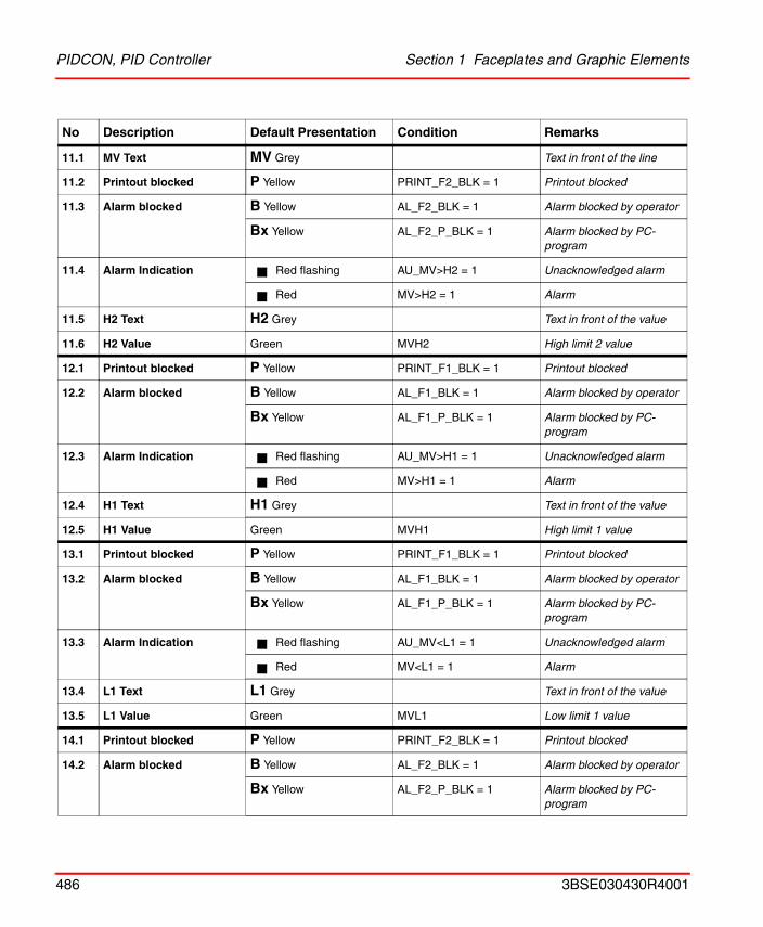
PIDCON, PID Controller Section 1 Faceplates and Graphic Elements
11.1 MV Text MV Grey Text in front of the line
11.2 Printout blocked P Yellow PRINT_F2_BLK = 1 Printout blocked
11.3 Alarm blocked B Yellow AL_F2_BLK = 1 Alarm blocked by operator
Bx Yellow AL_F2_P_BLK = 1 Alarm blocked by PC-program
11.4 Alarm Indication Red flashing AU_MV>H2 = 1 Unacknowledged alarm
Red MV>H2 = 1 Alarm
11.5 H2 Text H2 Grey Text in front of the value
11.6 H2 Value Green MVH2 High limit 2 value
12.1 Printout blocked P Yellow PRINT_F1_BLK = 1 Printout blocked
12.2 Alarm blocked B Yellow AL_F1_BLK = 1 Alarm blocked by operator
Bx Yellow AL_F1_P_BLK = 1 Alarm blocked by PC-program
12.3 Alarm Indication Red flashing AU_MV>H1 = 1 Unacknowledged alarm
Red MV>H1 = 1 Alarm
12.4 H1 Text H1 Grey Text in front of the value
12.5 H1 Value Green MVH1 High limit 1 value
13.1 Printout blocked P Yellow PRINT_F1_BLK = 1 Printout blocked
13.2 Alarm blocked B Yellow AL_F1_BLK = 1 Alarm blocked by operator
Bx Yellow AL_F1_P_BLK = 1 Alarm blocked by PC-program
13.3 Alarm Indication Red flashing AU_MV<L1 = 1 Unacknowledged alarm
Red MV<L1 = 1 Alarm
13.4 L1 Text L1 Grey Text in front of the value
13.5 L1 Value Green MVL1 Low limit 1 value
14.1 Printout blocked P Yellow PRINT_F2_BLK = 1 Printout blocked
14.2 Alarm blocked B Yellow AL_F2_BLK = 1 Alarm blocked by operator
Bx Yellow AL_F2_P_BLK = 1 Alarm blocked by PC-program
No Description Default Presentation Condition Remarks
486 3BSE030430R4001
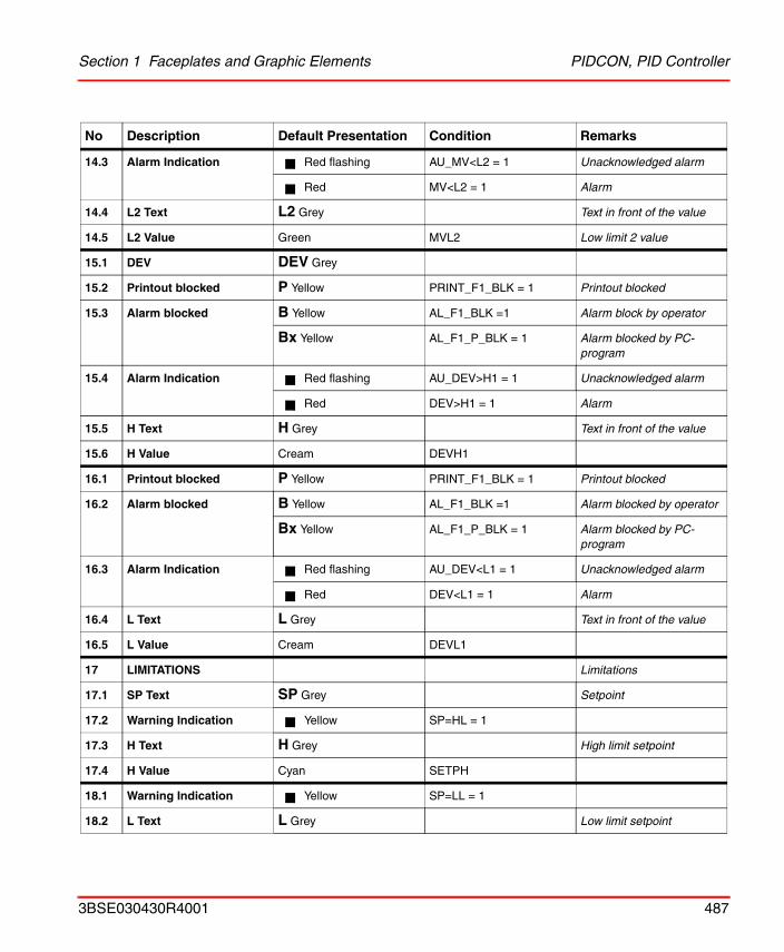
Section 1 Faceplates and Graphic Elements PIDCON, PID Controller
14.3 Alarm Indication Red flashing AU_MV<L2 = 1 Unacknowledged alarm
Red MV<L2 = 1 Alarm
14.4 L2 Text L2 Grey Text in front of the value
14.5 L2 Value Green MVL2 Low limit 2 value
15.1 DEV DEV Grey
15.2 Printout blocked P Yellow PRINT_F1_BLK = 1 Printout blocked
15.3 Alarm blocked B Yellow AL_F1_BLK =1 Alarm block by operator
Bx Yellow AL_F1_P_BLK = 1 Alarm blocked by PC-program
15.4 Alarm Indication Red flashing AU_DEV>H1 = 1 Unacknowledged alarm
Red DEV>H1 = 1 Alarm
15.5 H Text H Grey Text in front of the value
15.6 H Value Cream DEVH1
16.1 Printout blocked P Yellow PRINT_F1_BLK = 1 Printout blocked
16.2 Alarm blocked B Yellow AL_F1_BLK =1 Alarm blocked by operator
Bx Yellow AL_F1_P_BLK = 1 Alarm blocked by PC-program
16.3 Alarm Indication Red flashing AU_DEV<L1 = 1 Unacknowledged alarm
Red DEV<L1 = 1 Alarm
16.4 L Text L Grey Text in front of the value
16.5 L Value Cream DEVL1
17 LIMITATIONS Limitations
17.1 SP Text SP Grey Setpoint
17.2 Warning Indication Yellow SP=HL = 1
17.3 H Text H Grey High limit setpoint
17.4 H Value Cyan SETPH
18.1 Warning Indication Yellow SP=LL = 1
18.2 L Text L Grey Low limit setpoint
No Description Default Presentation Condition Remarks
3BSE030430R4001 487
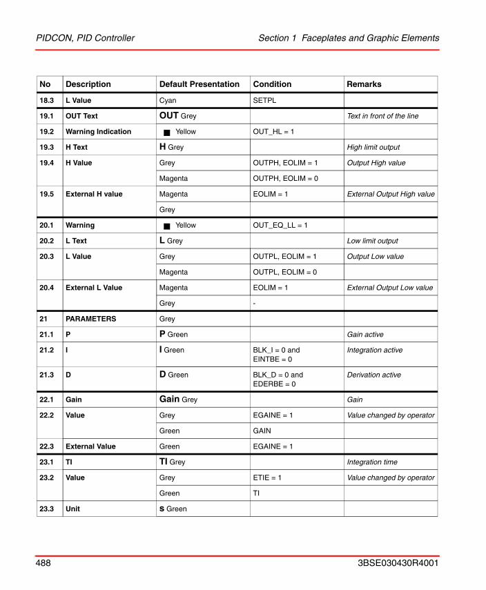
PIDCON, PID Controller Section 1 Faceplates and Graphic Elements
18.3 L Value Cyan SETPL
19.1 OUT Text OUT Grey Text in front of the line
19.2 Warning Indication Yellow OUT_HL = 1
19.3 H Text H Grey High limit output
19.4 H Value Grey OUTPH, EOLIM = 1 Output High value
Magenta OUTPH, EOLIM = 0
19.5 External H value Magenta EOLIM = 1 External Output High value
Grey
20.1 Warning Yellow OUT_EQ_LL = 1
20.2 L Text L Grey Low limit output
20.3 L Value Grey OUTPL, EOLIM = 1 Output Low value
Magenta OUTPL, EOLIM = 0
20.4 External L Value Magenta EOLIM = 1 External Output Low value
Grey -
21 PARAMETERS Grey
21.1 P P Green Gain active
21.2 I I Green BLK_I = 0 andEINTBE = 0
Integration active
21.3 D D Green BLK_D = 0 andEDERBE = 0
Derivation active
22.1 Gain Gain Grey Gain
22.2 Value Grey EGAINE = 1 Value changed by operator
Green GAIN
22.3 External Value Green EGAINE = 1
23.1 TI TI Grey Integration time
23.2 Value Grey ETIE = 1 Value changed by operator
Green TI
23.3 Unit s Green
No Description Default Presentation Condition Remarks
488 3BSE030430R4001
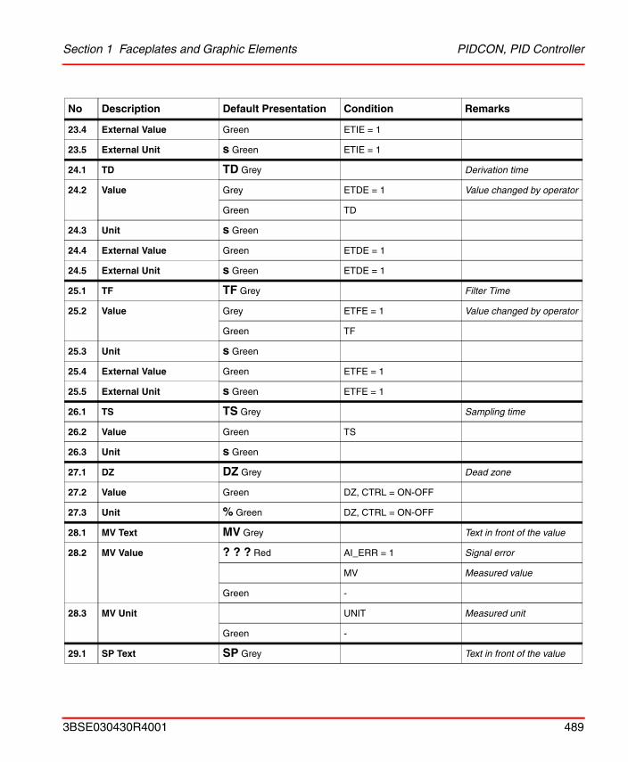
Section 1 Faceplates and Graphic Elements PIDCON, PID Controller
23.4 External Value Green ETIE = 1
23.5 External Unit s Green ETIE = 1
24.1 TD TD Grey Derivation time
24.2 Value Grey ETDE = 1 Value changed by operator
Green TD
24.3 Unit s Green
24.4 External Value Green ETDE = 1
24.5 External Unit s Green ETDE = 1
25.1 TF TF Grey Filter Time
25.2 Value Grey ETFE = 1 Value changed by operator
Green TF
25.3 Unit s Green
25.4 External Value Green ETFE = 1
25.5 External Unit s Green ETFE = 1
26.1 TS TS Grey Sampling time
26.2 Value Green TS
26.3 Unit s Green
27.1 DZ DZ Grey Dead zone
27.2 Value Green DZ, CTRL = ON-OFF
27.3 Unit % Green DZ, CTRL = ON-OFF
28.1 MV Text MV Grey Text in front of the value
28.2 MV Value ? ? ? Red AI_ERR = 1 Signal error
MV Measured value
Green -
28.3 MV Unit UNIT Measured unit
Green -
29.1 SP Text SP Grey Text in front of the value
No Description Default Presentation Condition Remarks
3BSE030430R4001 489
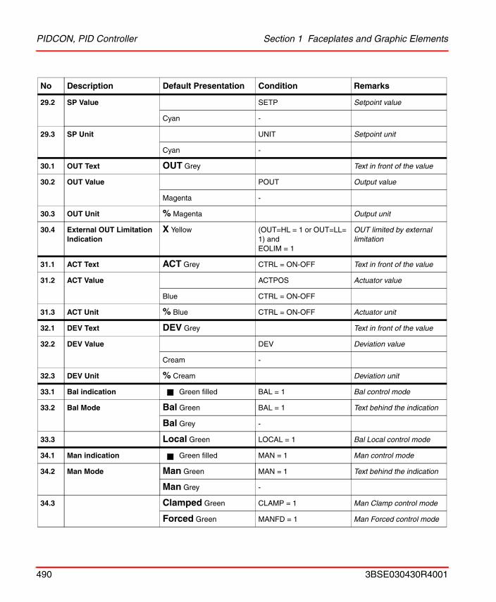
PIDCON, PID Controller Section 1 Faceplates and Graphic Elements
29.2 SP Value SETP Setpoint value
Cyan -
29.3 SP Unit UNIT Setpoint unit
Cyan -
30.1 OUT Text OUT Grey Text in front of the value
30.2 OUT Value POUT Output value
Magenta -
30.3 OUT Unit % Magenta Output unit
30.4 External OUT Limitation Indication
X Yellow (OUT=HL = 1 or OUT=LL= 1) and EOLIM = 1
OUT limited by external limitation
31.1 ACT Text ACT Grey CTRL = ON-OFF Text in front of the value
31.2 ACT Value ACTPOS Actuator value
Blue CTRL = ON-OFF
31.3 ACT Unit % Blue CTRL = ON-OFF Actuator unit
32.1 DEV Text DEV Grey Text in front of the value
32.2 DEV Value DEV Deviation value
Cream -
32.3 DEV Unit % Cream Deviation unit
33.1 Bal indication Green filled BAL = 1 Bal control mode
33.2 Bal Mode Bal Green BAL = 1 Text behind the indication
Bal Grey -
33.3 Local Green LOCAL = 1 Bal Local control mode
34.1 Man indication Green filled MAN = 1 Man control mode
34.2 Man Mode Man Green MAN = 1 Text behind the indication
Man Grey -
34.3 Clamped Green CLAMP = 1 Man Clamp control mode
Forced Green MANFD = 1 Man Forced control mode
No Description Default Presentation Condition Remarks
490 3BSE030430R4001
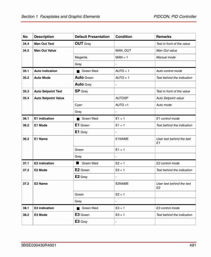
Section 1 Faceplates and Graphic Elements PIDCON, PID Controller
34.4 Man Out Text OUT Grey Text in front of the value
34.5 Man Out Value MAN_OUT Man Out value
Magenta MAN = 1 Manual mode
Grey -
35.1 Auto indication Green filled AUTO = 1 Auto control mode
35.2 Auto Mode Auto Green AUTO = 1 Text behind the indication
Auto Grey -
35.3 Auto Setpoint Text SP Grey Text in front of the value
35.4 Auto Setpoint Value AUTOSP Auto Setpoint value
Cyan AUTO =1 Auto mode
Grey -
36.1 E1 indication Green filled E1 = 1 E1 control mode
36.2 E1 Mode E1 Green E1 = 1 Text behind the indication
E1 Grey -
36.2 E1 Name E1NAME User text behind the text E1
Green E1 = 1
Grey -
37.1 E2 indication Green filled E2 = 1 E2 control mode
37.2 E2 Mode E2 Green E2 = 1 Text behind the indication
E2 Grey -
37.2 E2 Name E2NAME User text behind the text E2
Green E2 = 1
Grey -
38.1 E3 indication Green filled E3 = 1 E3 control mode
38.2 E3 Mode E3 Green E3 = 1 Text behind the indication
E3 Grey -
No Description Default Presentation Condition Remarks
3BSE030430R4001 491
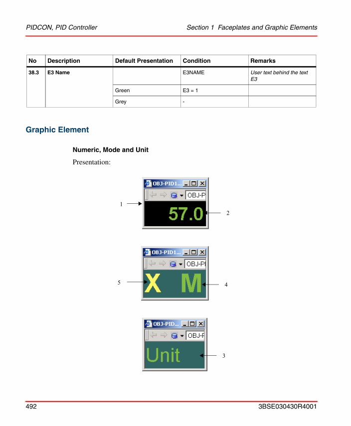
PIDCON, PID Controller Section 1 Faceplates and Graphic Elements
Graphic Element
Numeric, Mode and Unit
Presentation:
38.3 E3 Name E3NAME User text behind the text E3
Green E3 = 1
Grey -
No Description Default Presentation Condition Remarks
12
45
3
492 3BSE030430R4001
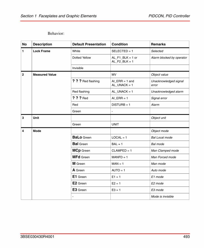
Section 1 Faceplates and Graphic Elements PIDCON, PID Controller
Behavior:
No Description Default Presentation Condition Remarks
1 Lock Frame White SELECTED = 1 Selected
Dotted Yellow AL_F1_BLK = 1 orAL_F2_BLK = 1
Alarm blocked by operator
Invisible
2 Measured Value MV Object value
? ? ? Red flashing AI_ERR = 1 and AL_UNACK = 1
Unacknowledged signal error
Red flashing AL_UNACK = 1 Unacknowledged alarm
? ? ? Red AI_ERR = 1 Signal error
Red DISTURB = 1 Alarm
Green -
3 Unit Object unit
Green UNIT
4 Mode Object mode
BaLo Green LOCAL = 1 Bal Local mode
Bal Green BAL = 1 Bal mode
MCp Green CLAMPED = 1 Man Clamped mode
MFd Green MANFD = 1 Man Forced mode
M Green MAN = 1 Man mode
A Green AUTO = 1 Auto mode
E1 Green E1 = 1 E1 mode
E2 Green E2 = 1 E2 mode
E3 Green E3 = 1 E3 mode
- Mode is invisible
3BSE030430R4001 493
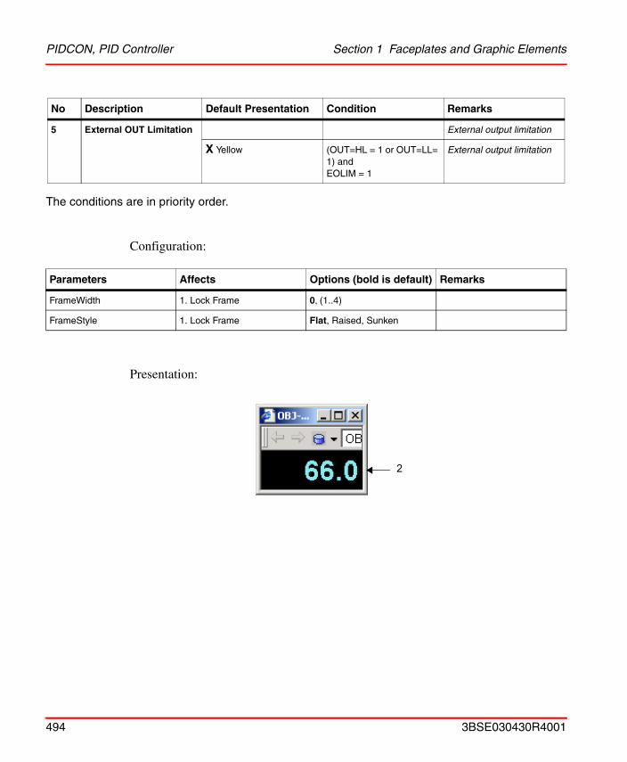
PIDCON, PID Controller Section 1 Faceplates and Graphic Elements
The conditions are in priority order.
Configuration:
Presentation:
5 External OUT Limitation External output limitation
X Yellow (OUT=HL = 1 or OUT=LL= 1) and EOLIM = 1
External output limitation
Parameters Affects Options (bold is default) Remarks
FrameWidth 1. Lock Frame 0, (1..4)
FrameStyle 1. Lock Frame Flat, Raised, Sunken
No Description Default Presentation Condition Remarks
2
494 3BSE030430R4001
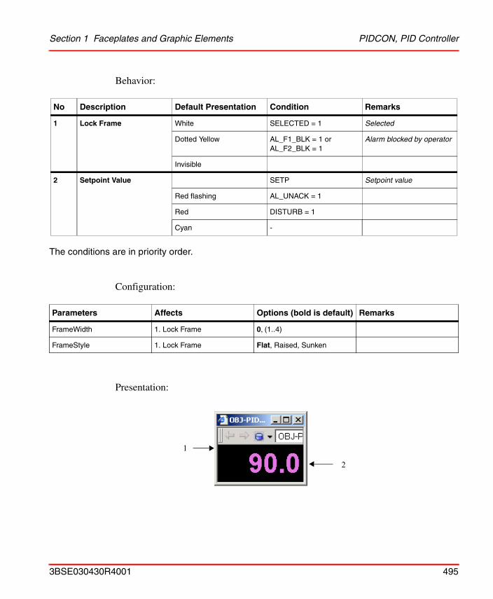
Section 1 Faceplates and Graphic Elements PIDCON, PID Controller
Behavior:
The conditions are in priority order.
Configuration:
Presentation:
No Description Default Presentation Condition Remarks
1 Lock Frame White SELECTED = 1 Selected
Dotted Yellow AL_F1_BLK = 1 orAL_F2_BLK = 1
Alarm blocked by operator
Invisible
2 Setpoint Value SETP Setpoint value
Red flashing AL_UNACK = 1
Red DISTURB = 1
Cyan -
Parameters Affects Options (bold is default) Remarks
FrameWidth 1. Lock Frame 0, (1..4)
FrameStyle 1. Lock Frame Flat, Raised, Sunken
1
2
3BSE030430R4001 495
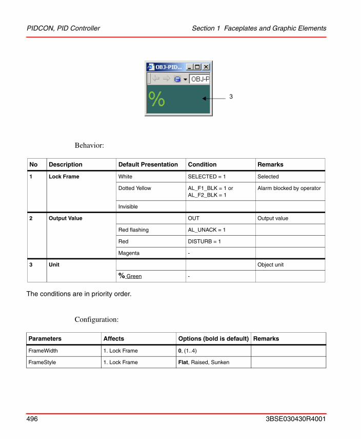
PIDCON, PID Controller Section 1 Faceplates and Graphic Elements
Behavior:
The conditions are in priority order.
Configuration:
No Description Default Presentation Condition Remarks
1 Lock Frame White SELECTED = 1 Selected
Dotted Yellow AL_F1_BLK = 1 orAL_F2_BLK = 1
Alarm blocked by operator
Invisible
2 Output Value OUT Output value
Red flashing AL_UNACK = 1
Red DISTURB = 1
Magenta -
3 Unit Object unit
% Green -
Parameters Affects Options (bold is default) Remarks
FrameWidth 1. Lock Frame 0, (1..4)
FrameStyle 1. Lock Frame Flat, Raised, Sunken
3
496 3BSE030430R4001
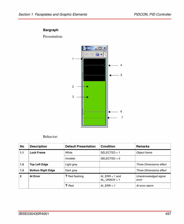
Section 1 Faceplates and Graphic Elements PIDCON, PID Controller
Bargraph
Presentation:
Behavior:
No Description Default Presentation Condition Remarks
1.1 Lock Frame White SELECTED = 1 Object frame
Invisible SELECTED = 0
1.2 Top Left Edge Light grey Three Dimensions effect
1.3 Bottom Right Edge Dark grey Three Dimensions effect
2 AI Error ? Red flashing AI_ERR = 1 and AL_UNACK = 1
Unacknowledged signal error
? Red AI_ERR = 1 AI error alarm
1
2
3
4
5
6
7
3BSE030430R4001 497
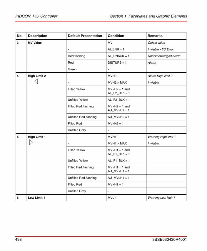
PIDCON, PID Controller Section 1 Faceplates and Graphic Elements
3 MV Value MV Object value
- AI_ERR = 1 Invisible - I/O Error
Red flashing AL_UNACK = 1 Unacknowledged alarm
Red DISTURB =1 Alarm
Green -
4 High Limit 2 MVH2 Alarm High limit 2
- MVH2 > MAX Invisible
Filled Yellow MV>H2 = 1 and AL_F2_BLK = 1
Unfilled Yellow AL_F2_BLK = 1
Filled Red flashing MV>H2 = 1 and AU_MV>H2 = 1
Unfilled Red flashing AU_MV>H2 = 1
Filled Red MV>H2 = 1
Unfilled Grey -
5 High Limit 1 MVH1 Warning High limit 1
- MVH1 > MAX Invisible
Filled Yellow MV>H1 = 1 and AL_F1_BLK = 1
Unfilled Yellow AL_F1_BLK = 1
Filled Red flashing MV>H1 = 1 and AU_MV>H1 = 1
Unfilled Red flashing AU_MV>H1 = 1
Filled Red MV>H1 = 1
Unfilled Grey -
6 Low Limit 1 MVL1 Warning Low limit 1
No Description Default Presentation Condition Remarks
498 3BSE030430R4001
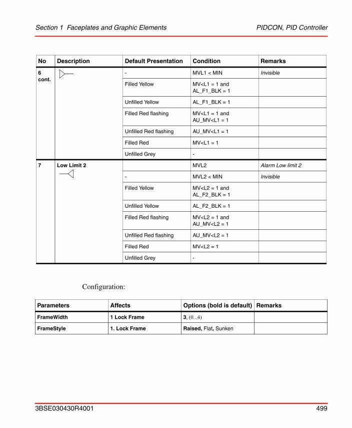
Section 1 Faceplates and Graphic Elements PIDCON, PID Controller
Configuration:
6 cont.
- MVL1 < MIN Invisible
Filled Yellow MV<L1 = 1 and AL_F1_BLK = 1
Unfilled Yellow AL_F1_BLK = 1
Filled Red flashing MV<L1 = 1 and AU_MV<L1 = 1
Unfilled Red flashing AU_MV<L1 = 1
Filled Red MV<L1 = 1
Unfilled Grey -
7 Low Limit 2 MVL2 Alarm Low limit 2
- MVL2 < MIN Invisible
Filled Yellow MV<L2 = 1 and AL_F2_BLK = 1
Unfilled Yellow AL_F2_BLK = 1
Filled Red flashing MV<L2 = 1 and AU_MV<L2 = 1
Unfilled Red flashing AU_MV<L2 = 1
Filled Red MV<L2 = 1
Unfilled Grey -
Parameters Affects Options (bold is default) Remarks
FrameWidth 1 Lock Frame 3, (0...4)
FrameStyle 1. Lock Frame Raised, Flat, Sunken
No Description Default Presentation Condition Remarks
3BSE030430R4001 499
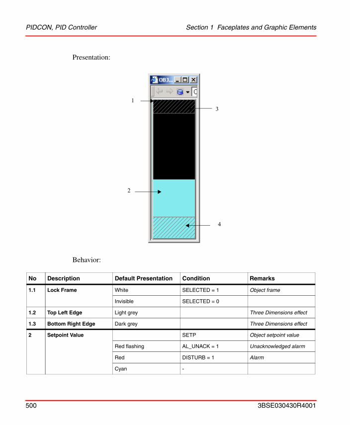
PIDCON, PID Controller Section 1 Faceplates and Graphic Elements
Presentation:
Behavior:
No Description Default Presentation Condition Remarks
1.1 Lock Frame White SELECTED = 1 Object frame
Invisible SELECTED = 0
1.2 Top Left Edge Light grey Three Dimensions effect
1.3 Bottom Right Edge Dark grey Three Dimensions effect
2 Setpoint Value SETP Object setpoint value
Red flashing AL_UNACK = 1 Unacknowledged alarm
Red DISTURB = 1 Alarm
Cyan -
3
4
1
2
500 3BSE030430R4001

Section 1 Faceplates and Graphic Elements PIDCON, PID Controller
Configuration:
3 High SP Limit SETPH Upper limit setpoint
Yellow SP=HL = 1 Limitation line and mesh
Grey -
4 Low SP Limit SETPH Lower limit setpoint
Yellow SP=HL = 1 Limitation line and mesh
Grey -
Parameters Affects Options (bold is default) Remarks
FrameWidth 1 Lock Frame 3, (0...4)
FrameStyle 1. Lock Frame Raised, Flat, Sunken
No Description Default Presentation Condition Remarks
3BSE030430R4001 501
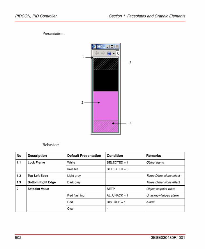
PIDCON, PID Controller Section 1 Faceplates and Graphic Elements
Presentation:
Behavior:
No Description Default Presentation Condition Remarks
1.1 Lock Frame White SELECTED = 1 Object frame
Invisible SELECTED = 0
1.2 Top Left Edge Light grey Three Dimensions effect
1.3 Bottom Right Edge Dark grey Three Dimensions effect
2 Setpoint Value SETP Object setpoint value
Red flashing AL_UNACK = 1 Unacknowledged alarm
Red DISTURB = 1 Alarm
Cyan -
3
4
1
2
502 3BSE030430R4001
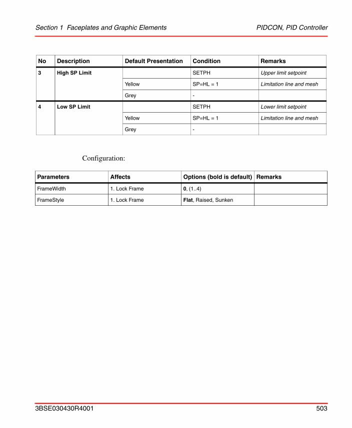
Section 1 Faceplates and Graphic Elements PIDCON, PID Controller
Configuration:
3 High SP Limit SETPH Upper limit setpoint
Yellow SP=HL = 1 Limitation line and mesh
Grey -
4 Low SP Limit SETPH Lower limit setpoint
Yellow SP=HL = 1 Limitation line and mesh
Grey -
Parameters Affects Options (bold is default) Remarks
FrameWidth 1. Lock Frame 0, (1..4)
FrameStyle 1. Lock Frame Flat, Raised, Sunken
No Description Default Presentation Condition Remarks
3BSE030430R4001 503
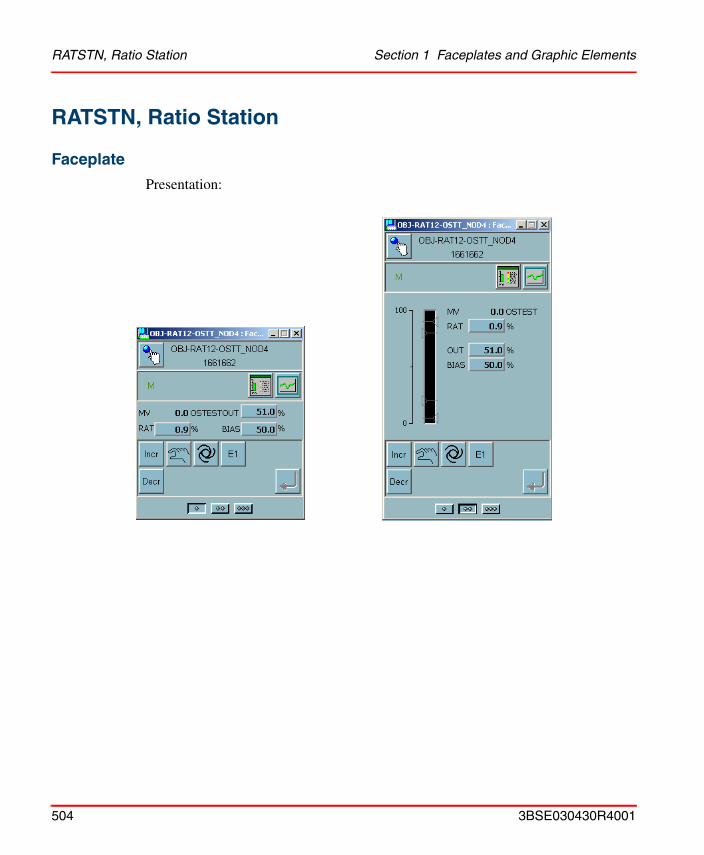
RATSTN, Ratio Station Section 1 Faceplates and Graphic Elements
RATSTN, Ratio Station
Faceplate
Presentation:
504 3BSE030430R4001
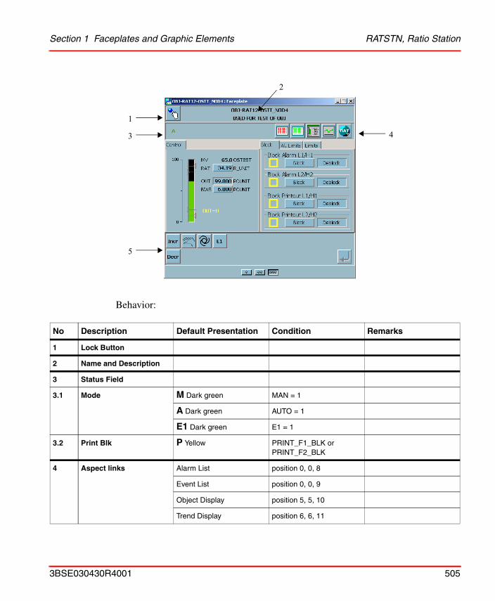
Section 1 Faceplates and Graphic Elements RATSTN, Ratio Station
Behavior:
No Description Default Presentation Condition Remarks
1 Lock Button
2 Name and Description
3 Status Field
3.1 Mode M Dark green MAN = 1
A Dark green AUTO = 1
E1 Dark green E1 = 1
3.2 Print Blk P Yellow PRINT_F1_BLK or PRINT_F2_BLK
4 Aspect links Alarm List position 0, 0, 8
Event List position 0, 0, 9
Object Display position 5, 5, 10
Trend Display position 6, 6, 11
1
3
5
4
2
3BSE030430R4001 505
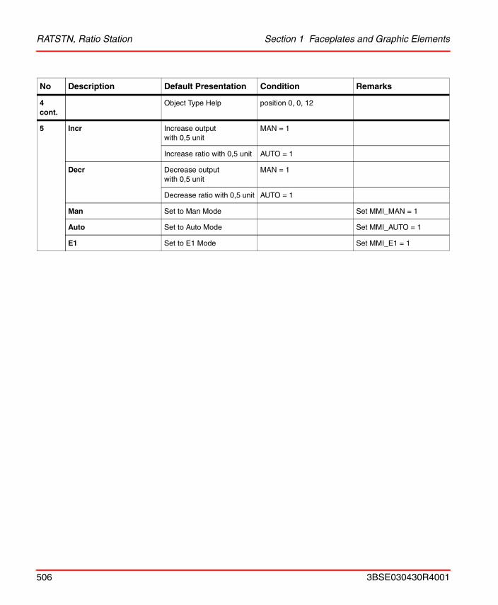
RATSTN, Ratio Station Section 1 Faceplates and Graphic Elements
4 cont.
Object Type Help position 0, 0, 12
5 Incr Increase outputwith 0,5 unit
MAN = 1
Increase ratio with 0,5 unit AUTO = 1
Decr Decrease output with 0,5 unit
MAN = 1
Decrease ratio with 0,5 unit AUTO = 1
Man Set to Man Mode Set MMI_MAN = 1
Auto Set to Auto Mode Set MMI_AUTO = 1
E1 Set to E1 Mode Set MMI_E1 = 1
No Description Default Presentation Condition Remarks
506 3BSE030430R4001
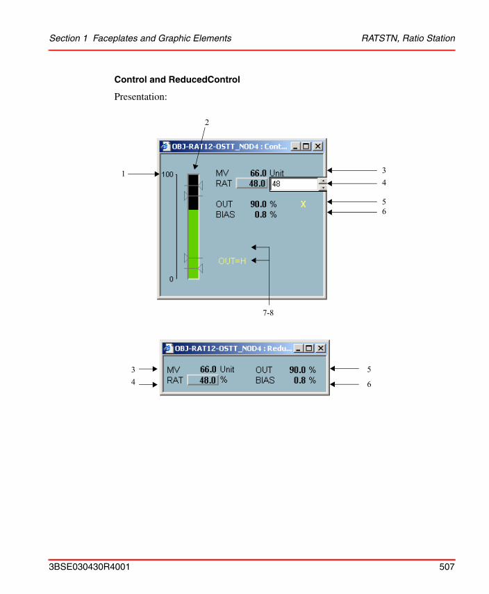
Section 1 Faceplates and Graphic Elements RATSTN, Ratio Station
Control and ReducedControl
Presentation:
1 3
7-8
4
56
2
5
6
34
3BSE030430R4001 507
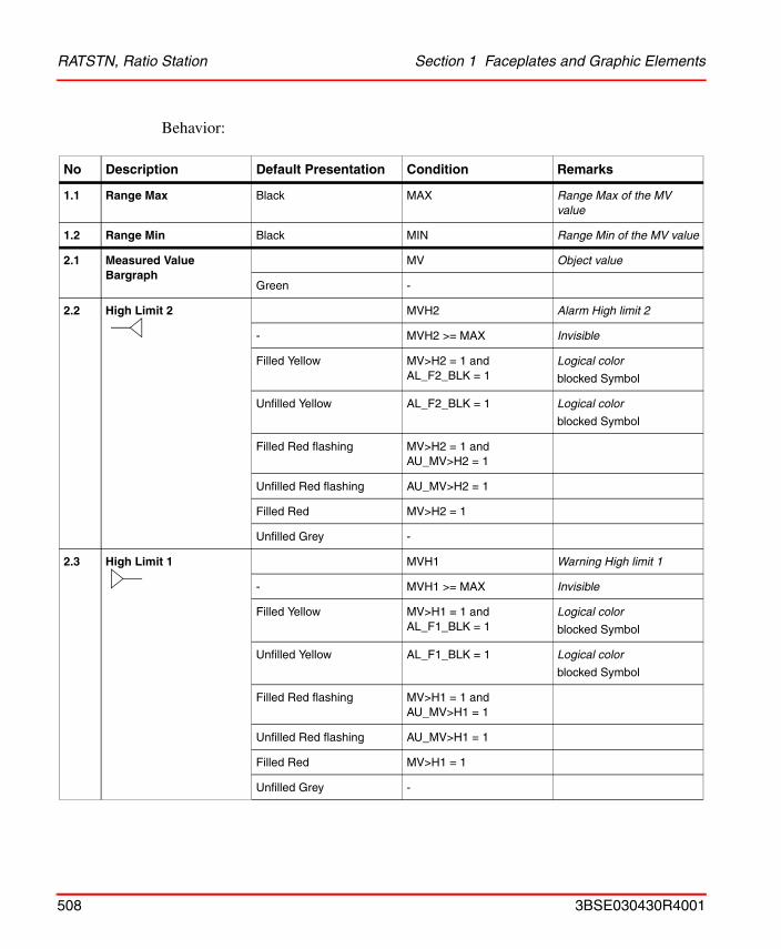
RATSTN, Ratio Station Section 1 Faceplates and Graphic Elements
Behavior:
No Description Default Presentation Condition Remarks
1.1 Range Max Black MAX Range Max of the MV value
1.2 Range Min Black MIN Range Min of the MV value
2.1 Measured Value Bargraph
MV Object value
Green -
2.2 High Limit 2 MVH2 Alarm High limit 2
- MVH2 >= MAX Invisible
Filled Yellow MV>H2 = 1 and AL_F2_BLK = 1
Logical color
blocked Symbol
Unfilled Yellow AL_F2_BLK = 1 Logical color
blocked Symbol
Filled Red flashing MV>H2 = 1 and AU_MV>H2 = 1
Unfilled Red flashing AU_MV>H2 = 1
Filled Red MV>H2 = 1
Unfilled Grey -
2.3 High Limit 1 MVH1 Warning High limit 1
- MVH1 >= MAX Invisible
Filled Yellow MV>H1 = 1 and AL_F1_BLK = 1
Logical color
blocked Symbol
Unfilled Yellow AL_F1_BLK = 1 Logical color
blocked Symbol
Filled Red flashing MV>H1 = 1 and AU_MV>H1 = 1
Unfilled Red flashing AU_MV>H1 = 1
Filled Red MV>H1 = 1
Unfilled Grey -
508 3BSE030430R4001
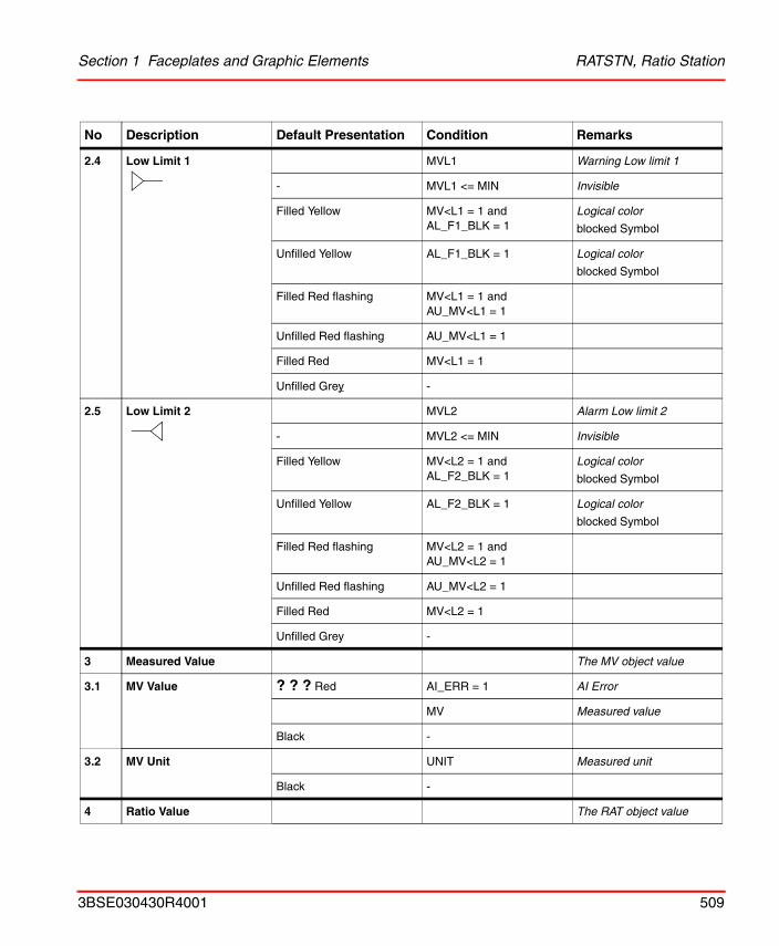
Section 1 Faceplates and Graphic Elements RATSTN, Ratio Station
2.4 Low Limit 1 MVL1 Warning Low limit 1
- MVL1 <= MIN Invisible
Filled Yellow MV<L1 = 1 and AL_F1_BLK = 1
Logical color
blocked Symbol
Unfilled Yellow AL_F1_BLK = 1 Logical color
blocked Symbol
Filled Red flashing MV<L1 = 1 and AU_MV<L1 = 1
Unfilled Red flashing AU_MV<L1 = 1
Filled Red MV<L1 = 1
Unfilled Grey -
2.5 Low Limit 2 MVL2 Alarm Low limit 2
- MVL2 <= MIN Invisible
Filled Yellow MV<L2 = 1 and AL_F2_BLK = 1
Logical color
blocked Symbol
Unfilled Yellow AL_F2_BLK = 1 Logical color
blocked Symbol
Filled Red flashing MV<L2 = 1 and AU_MV<L2 = 1
Unfilled Red flashing AU_MV<L2 = 1
Filled Red MV<L2 = 1
Unfilled Grey -
3 Measured Value The MV object value
3.1 MV Value ? ? ? Red AI_ERR = 1 AI Error
MV Measured value
Black -
3.2 MV Unit UNIT Measured unit
Black -
4 Ratio Value The RAT object value
No Description Default Presentation Condition Remarks
3BSE030430R4001 509
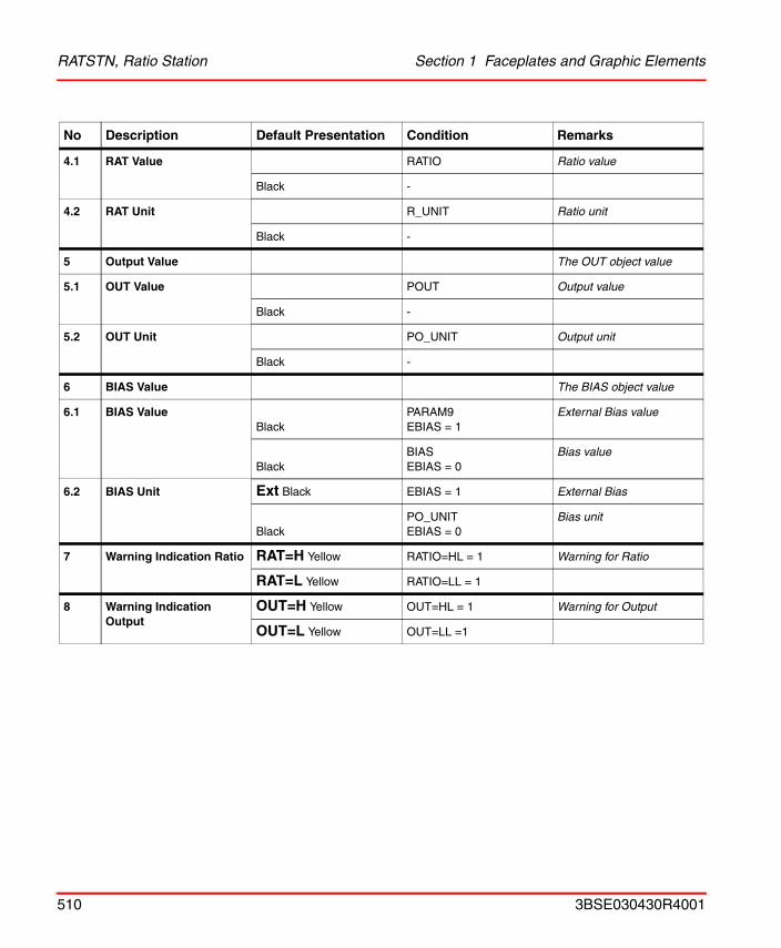
RATSTN, Ratio Station Section 1 Faceplates and Graphic Elements
4.1 RAT Value RATIO Ratio value
Black -
4.2 RAT Unit R_UNIT Ratio unit
Black -
5 Output Value The OUT object value
5.1 OUT Value POUT Output value
Black -
5.2 OUT Unit PO_UNIT Output unit
Black -
6 BIAS Value The BIAS object value
6.1 BIAS ValueBlack
PARAM9EBIAS = 1
External Bias value
BlackBIASEBIAS = 0
Bias value
6.2 BIAS Unit Ext Black EBIAS = 1 External Bias
BlackPO_UNITEBIAS = 0
Bias unit
7 Warning Indication Ratio RAT=H Yellow RATIO=HL = 1 Warning for Ratio
RAT=L Yellow RATIO=LL = 1
8 Warning Indication Output
OUT=H Yellow OUT=HL = 1 Warning for Output
OUT=L Yellow OUT=LL =1
No Description Default Presentation Condition Remarks
510 3BSE030430R4001
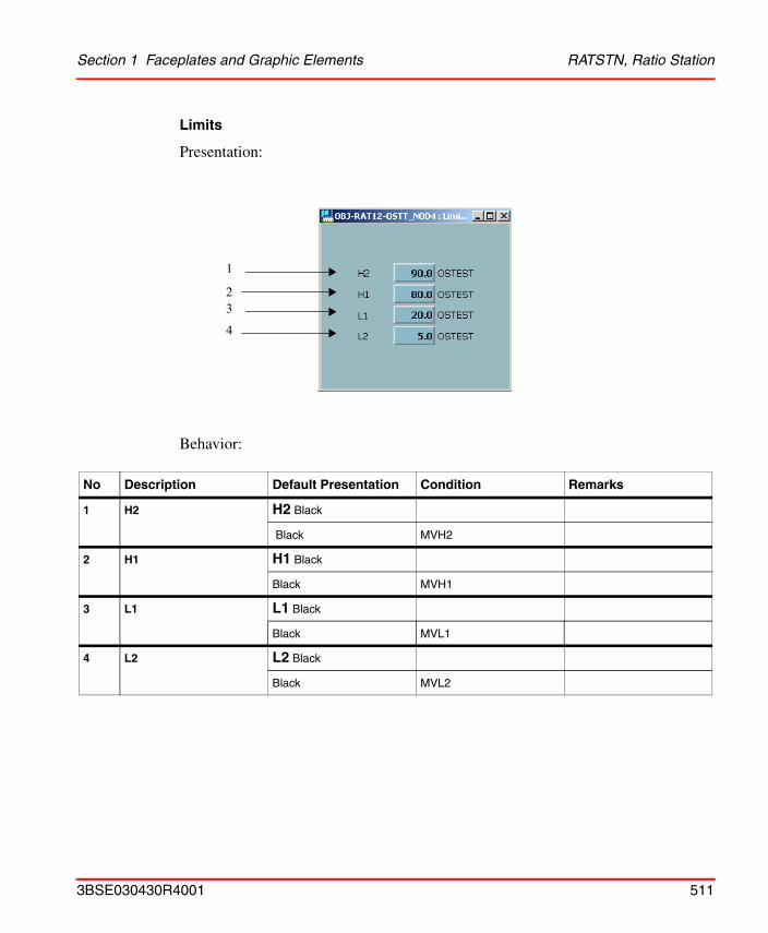
Section 1 Faceplates and Graphic Elements RATSTN, Ratio Station
Limits
Presentation:
Behavior:
No Description Default Presentation Condition Remarks
1 H2 H2 Black
Black MVH2
2 H1 H1 Black
Black MVH1
3 L1 L1 Black
Black MVL1
4 L2 L2 Black
Black MVL2
1
23
4
3BSE030430R4001 511
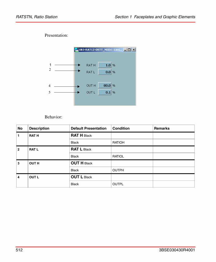
RATSTN, Ratio Station Section 1 Faceplates and Graphic Elements
Presentation:
Behavior:
No Description Default Presentation Condition Remarks
1 RAT H RAT H Black
Black RATIOH
2 RAT L RAT L Black
Black RATIOL
3 OUT H OUT H Black
Black OUTPH
4 OUT L OUT L Black
Black OUTPL
12
4
5
512 3BSE030430R4001
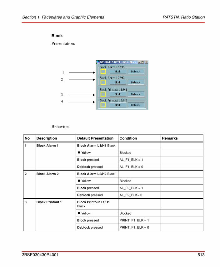
Section 1 Faceplates and Graphic Elements RATSTN, Ratio Station
Block
Presentation:
Behavior:
No Description Default Presentation Condition Remarks
1 Block Alarm 1 Block Alarm L1/H1 Black
! Yellow Blocked
Block pressed AL_F1_BLK = 1
Deblock pressed AL_F1_BLK = 0
2 Block Alarm 2 Block Alarm L2/H2 Black
! Yellow Blocked
Block pressed AL_F2_BLK = 1
Deblock pressed AL_F2_BLK= 0
3 Block Printout 1 Block Printout L1/H1 Black
! Yellow Blocked
Block pressed PRINT_F1_BLK = 1
Deblock pressed PRINT_F1_BLK = 0
1
3
4
2
3BSE030430R4001 513
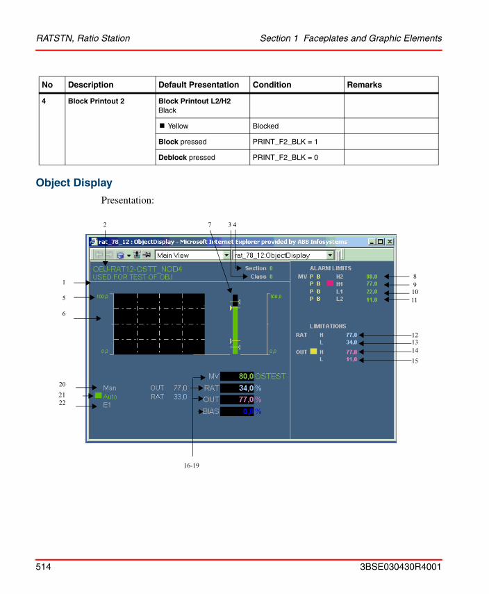
RATSTN, Ratio Station Section 1 Faceplates and Graphic Elements
Object Display
Presentation:
4 Block Printout 2 Block Printout L2/H2 Black
! Yellow Blocked
Block pressed PRINT_F2_BLK = 1
Deblock pressed PRINT_F2_BLK = 0
No Description Default Presentation Condition Remarks
8
11
12
2 3 47
202122
16-19
910
131415
1
5
6
514 3BSE030430R4001
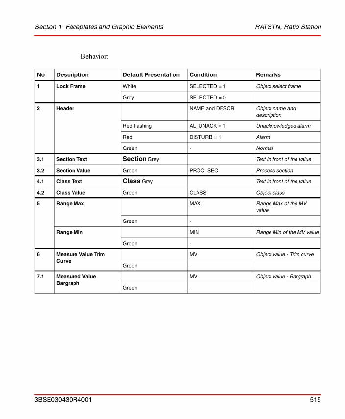
Section 1 Faceplates and Graphic Elements RATSTN, Ratio Station
Behavior:
No Description Default Presentation Condition Remarks
1 Lock Frame White SELECTED = 1 Object select frame
Grey SELECTED = 0
2 Header NAME and DESCR Object name and description
Red flashing AL_UNACK = 1 Unacknowledged alarm
Red DISTURB = 1 Alarm
Green - Normal
3.1 Section Text Section Grey Text in front of the value
3.2 Section Value Green PROC_SEC Process section
4.1 Class Text Class Grey Text in front of the value
4.2 Class Value Green CLASS Object class
5 Range Max MAX Range Max of the MV value
Green -
Range Min MIN Range Min of the MV value
Green -
6 Measure Value Trim Curve
MV Object value - Trim curve
Green -
7.1 Measured Value Bargraph
MV Object value - Bargraph
Green -
3BSE030430R4001 515
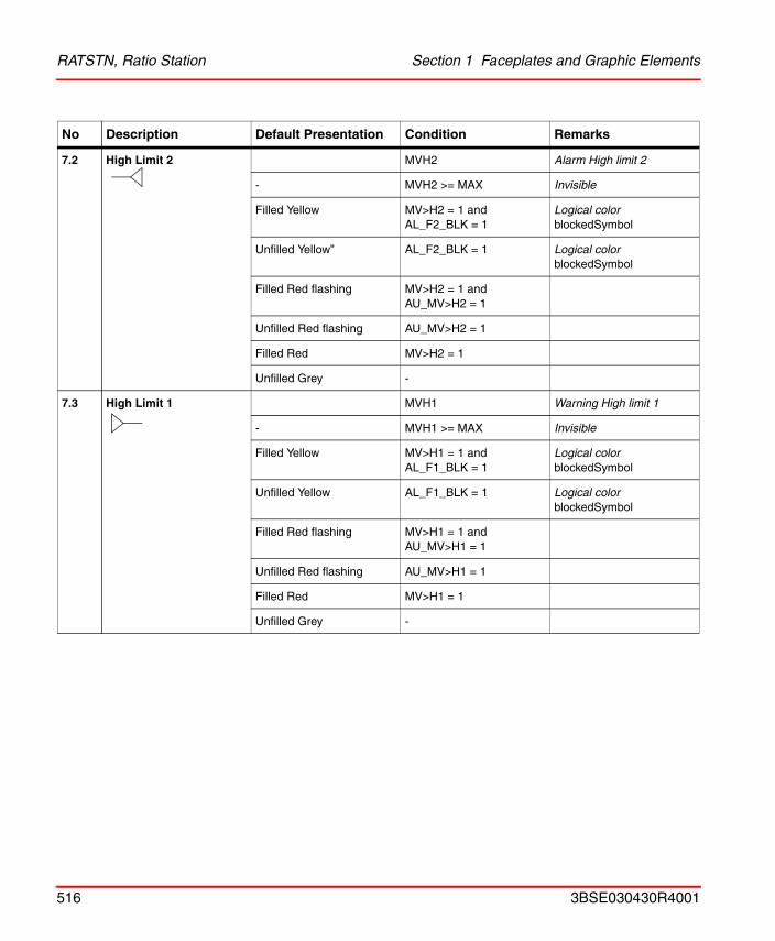
RATSTN, Ratio Station Section 1 Faceplates and Graphic Elements
7.2 High Limit 2 MVH2 Alarm High limit 2
- MVH2 >= MAX Invisible
Filled Yellow MV>H2 = 1 and AL_F2_BLK = 1
Logical colorblockedSymbol
Unfilled Yellow” AL_F2_BLK = 1 Logical colorblockedSymbol
Filled Red flashing MV>H2 = 1 and AU_MV>H2 = 1
Unfilled Red flashing AU_MV>H2 = 1
Filled Red MV>H2 = 1
Unfilled Grey -
7.3 High Limit 1 MVH1 Warning High limit 1
- MVH1 >= MAX Invisible
Filled Yellow MV>H1 = 1 and AL_F1_BLK = 1
Logical colorblockedSymbol
Unfilled Yellow AL_F1_BLK = 1 Logical colorblockedSymbol
Filled Red flashing MV>H1 = 1 and AU_MV>H1 = 1
Unfilled Red flashing AU_MV>H1 = 1
Filled Red MV>H1 = 1
Unfilled Grey -
No Description Default Presentation Condition Remarks
516 3BSE030430R4001
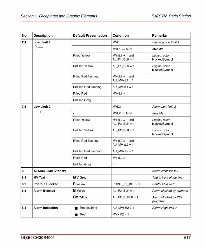
Section 1 Faceplates and Graphic Elements RATSTN, Ratio Station
7.4 Low Limit 1 MVL1 Warning Low limit 1
- MVL1 <= MIN Invisible
Filled Yellow MV<L1 = 1 and AL_F1_BLK = 1
Logical colorblockedSymbol
Unfilled Yellow AL_F1_BLK = 1 Logical colorblockedSymbol
Filled Red flashing MV<L1 = 1 and AU_MV<L1 = 1
Unfilled Red flashing AU_MV<L1 = 1
Filled Red MV<L1 = 1
Unfilled Grey -
7.5 Low Limit 2 MVL2 Alarm Low limit 2
- MVL2 <= MIN Invisible
Filled Yellow MV<L2 = 1 and AL_F2_BLK = 1
Logical colorblockedSymbol
Unfilled Yellow AL_F2_BLK = 1 Logical colorblockedSymbol
Filled Red flashing MV<L2 = 1 and AU_MV<L2 = 1
Unfilled Red flashing AU_MV<L2 = 1
Filled Red MV<L2 = 1
Unfilled Grey -
8 ALARM LIMITS for MV Alarm limits for MV
8.1 MV Text MV Grey Text in front of the line
8.2 Printout Blocked P Yellow PRINT_F2_BLK = 1 Printout blocked
8.3 Alarm Blocked B Yellow AL_F2_BLK = 1 Alarm blocked by operator
Bx Yellow AL_F2_P_BLK = 1 Alarm blocked by PC-program
8.4 Alarm Indication Red flashing AU_MV>H2 = 1 Alarm High limit 2
Red MV> H2 = 1
No Description Default Presentation Condition Remarks
3BSE030430R4001 517
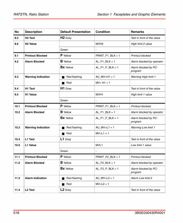
RATSTN, Ratio Station Section 1 Faceplates and Graphic Elements
8.5 H2 Text H2 Grey Text in front of the value
8.6 H2 Value MVH2 High limit 2 value
Green -
9.1 Printout Blocked P Yellow PRINT_F1_BLK = 1 Printout blocked
9.2 Alarm Blocked B Yellow AL_F1_BLK = 1 Alarm blocked by operator
Bx Yellow AL_F1_P_BLK = 1 Alarm blocked by PC-program
9.3 Warning Indication Red flashing AU_MV>H1 = 1 Warning High limit 1
Red MV> H1 = 1
9.4 H1 Text H1 Grey Text in front of the value
9.5 H1 Value MVH1 High limit 1 value
Green -
10.1 Printout Blocked P Yellow PRINT_F1_BLK = 1 Printout blocked
10.2 Alarm Blocked B Yellow AL_F1_BLK = 1 Alarm blocked by operator
Bx Yellow AL_F1_P_BLK = 1 Alarm blocked by PC-program
10.3 Warning Indication Red flashing AU_MV<L1 = 1 Warning Low limit 1
Red MV<L1 = 1
10.4 L1 Text L1 Grey Text in front of the value
10.5 L1 Value MVL1 Low limit 1 value
Green -
11.1 Printout Blocked P Yellow PRINT_F2_BLK = 1 Printout blocked
11.2 Alarm Blocked B Yellow AL_F2_BLK = 1 Alarm blocked by operator
Bx Yellow AL_F2_P_BLK = 1 Alarm blocked by PC-program
11.3 Alarm Indication Red flashing AU_MV<L2 = 1 Alarm Low limit 2
Red MV<L2 = 1
11.4 L2 Text L2 Grey Text in front of the value
No Description Default Presentation Condition Remarks
518 3BSE030430R4001
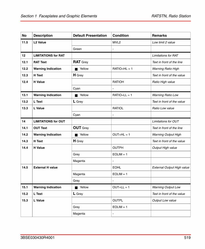
Section 1 Faceplates and Graphic Elements RATSTN, Ratio Station
11.5 L2 Value MVL2 Low limit 2 value
Green -
12 LIMITATIONS for RAT Limitations for RAT
12.1 RAT Text RAT Grey Text in front of the line
12.2 Warning Indication Yellow RATIO=HL = 1 Warning Ratio High
12.3 H Text H Grey Text in front of the value
12.4 H Value RATIOH Ratio High value
Cyan -
13.1 Warning Indication Yellow RATIO=LL = 1 Warning Ratio Low
13.2 L Text L Grey Text in front of the value
13.3 L Value RATIOL Ratio Low value
Cyan -
14 LIMITATIONS for OUT Limitations for OUT
14.1 OUT Text OUT Grey Text in front of the line
14.2 Warning Indication Yellow OUT=HL = 1 Warning Output High
14.3 H Text H Grey Text in front of the value
14.4 H Value OUTPH Output High value
Grey EOLIM = 1
Magenta -
14.5 External H value EOHL External Output High value
Magenta EOLIM = 1
Grey -
15.1 Warning Indication Yellow OUT=LL = 1 Warning Output Low
15.2 L Text L Grey Text in front of the value
15.3 L Value OUTPL Output Low value
Grey EOLIM = 1
Magenta -
No Description Default Presentation Condition Remarks
3BSE030430R4001 519
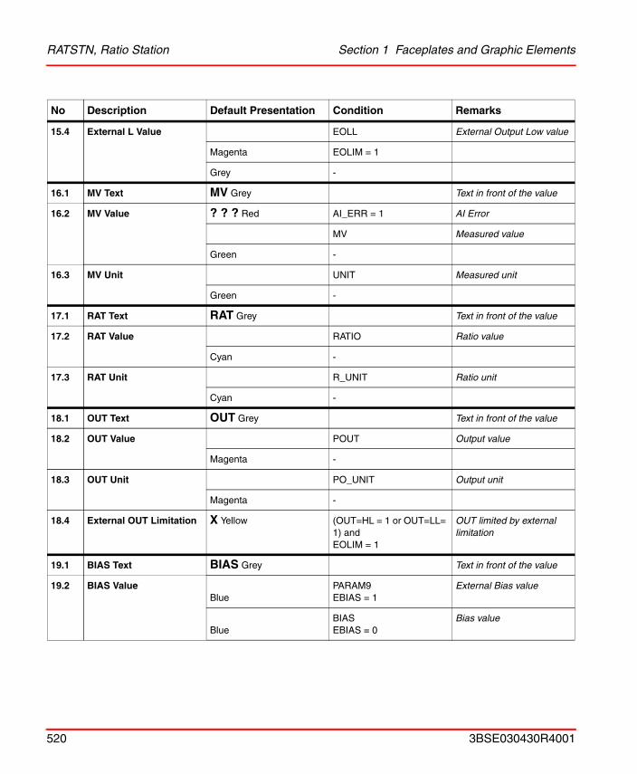
RATSTN, Ratio Station Section 1 Faceplates and Graphic Elements
15.4 External L Value EOLL External Output Low value
Magenta EOLIM = 1
Grey -
16.1 MV Text MV Grey Text in front of the value
16.2 MV Value ? ? ? Red AI_ERR = 1 AI Error
MV Measured value
Green -
16.3 MV Unit UNIT Measured unit
Green -
17.1 RAT Text RAT Grey Text in front of the value
17.2 RAT Value RATIO Ratio value
Cyan -
17.3 RAT Unit R_UNIT Ratio unit
Cyan -
18.1 OUT Text OUT Grey Text in front of the value
18.2 OUT Value POUT Output value
Magenta -
18.3 OUT Unit PO_UNIT Output unit
Magenta -
18.4 External OUT Limitation X Yellow (OUT=HL = 1 or OUT=LL= 1) and EOLIM = 1
OUT limited by external limitation
19.1 BIAS Text BIAS Grey Text in front of the value
19.2 BIAS ValueBlue
PARAM9EBIAS = 1
External Bias value
BlueBIASEBIAS = 0
Bias value
No Description Default Presentation Condition Remarks
520 3BSE030430R4001
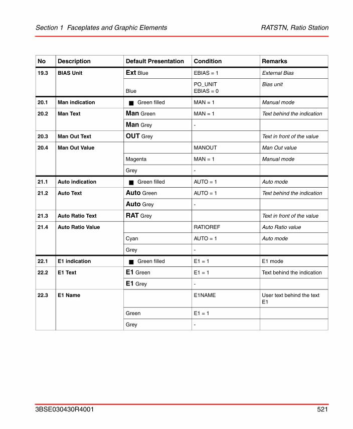
Section 1 Faceplates and Graphic Elements RATSTN, Ratio Station
19.3 BIAS Unit Ext Blue EBIAS = 1 External Bias
BluePO_UNITEBIAS = 0
Bias unit
20.1 Man indication Green filled MAN = 1 Manual mode
20.2 Man Text Man Green MAN = 1 Text behind the indication
Man Grey -
20.3 Man Out Text OUT Grey Text in front of the value
20.4 Man Out Value MANOUT Man Out value
Magenta MAN = 1 Manual mode
Grey -
21.1 Auto indication Green filled AUTO = 1 Auto mode
21.2 Auto Text Auto Green AUTO = 1 Text behind the indication
Auto Grey -
21.3 Auto Ratio Text RAT Grey Text in front of the value
21.4 Auto Ratio Value RATIOREF Auto Ratio value
Cyan AUTO = 1 Auto mode
Grey -
22.1 E1 indication Green filled E1 = 1 E1 mode
22.2 E1 Text E1 Green E1 = 1 Text behind the indication
E1 Grey -
22.3 E1 Name E1NAME User text behind the text E1
Green E1 = 1
Grey -
No Description Default Presentation Condition Remarks
3BSE030430R4001 521
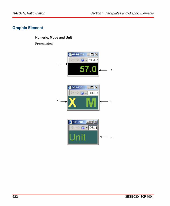
RATSTN, Ratio Station Section 1 Faceplates and Graphic Elements
Graphic Element
Numeric, Mode and Unit
Presentation:
1
2
45
3
522 3BSE030430R4001
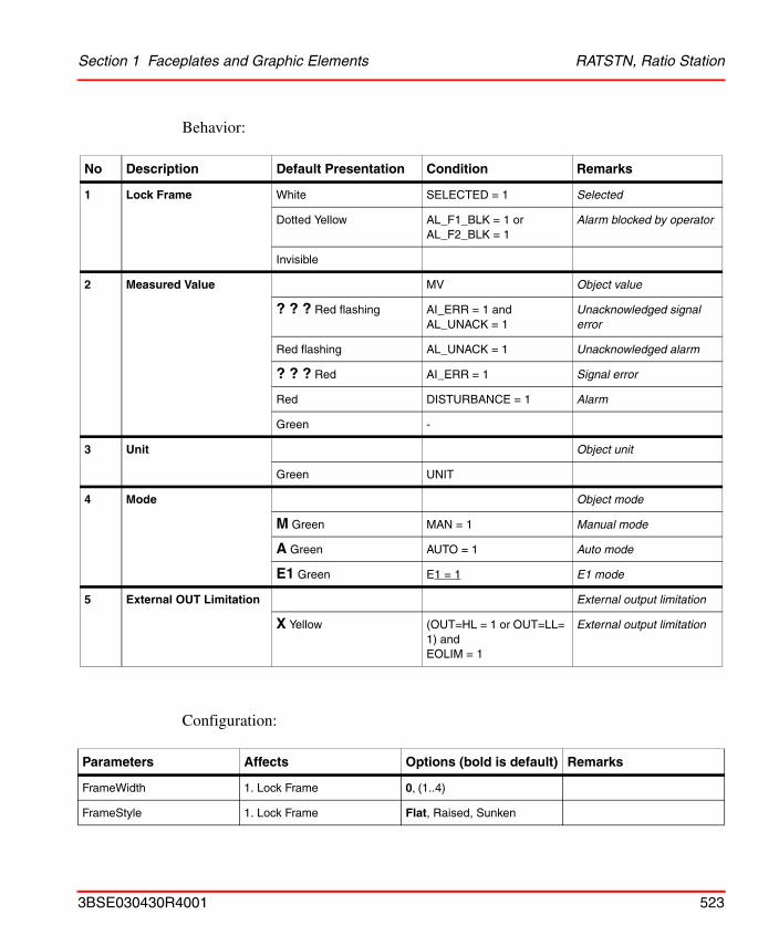
Section 1 Faceplates and Graphic Elements RATSTN, Ratio Station
Behavior:
Configuration:
No Description Default Presentation Condition Remarks
1 Lock Frame White SELECTED = 1 Selected
Dotted Yellow AL_F1_BLK = 1 orAL_F2_BLK = 1
Alarm blocked by operator
Invisible
2 Measured Value MV Object value
? ? ? Red flashing AI_ERR = 1 and AL_UNACK = 1
Unacknowledged signal error
Red flashing AL_UNACK = 1 Unacknowledged alarm
? ? ? Red AI_ERR = 1 Signal error
Red DISTURBANCE = 1 Alarm
Green -
3 Unit Object unit
Green UNIT
4 Mode Object mode
M Green MAN = 1 Manual mode
A Green AUTO = 1 Auto mode
E1 Green E1 = 1 E1 mode
5 External OUT Limitation External output limitation
X Yellow (OUT=HL = 1 or OUT=LL= 1) and EOLIM = 1
External output limitation
Parameters Affects Options (bold is default) Remarks
FrameWidth 1. Lock Frame 0, (1..4)
FrameStyle 1. Lock Frame Flat, Raised, Sunken
3BSE030430R4001 523
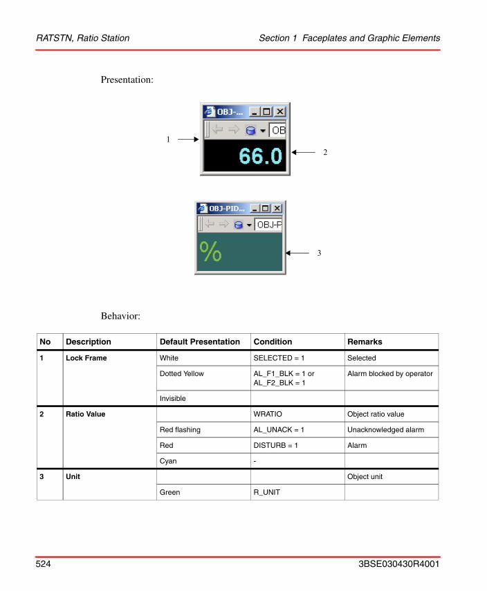
RATSTN, Ratio Station Section 1 Faceplates and Graphic Elements
Presentation:
Behavior:
No Description Default Presentation Condition Remarks
1 Lock Frame White SELECTED = 1 Selected
Dotted Yellow AL_F1_BLK = 1 orAL_F2_BLK = 1
Alarm blocked by operator
Invisible
2 Ratio Value WRATIO Object ratio value
Red flashing AL_UNACK = 1 Unacknowledged alarm
Red DISTURB = 1 Alarm
Cyan -
3 Unit Object unit
Green R_UNIT
12
3
524 3BSE030430R4001
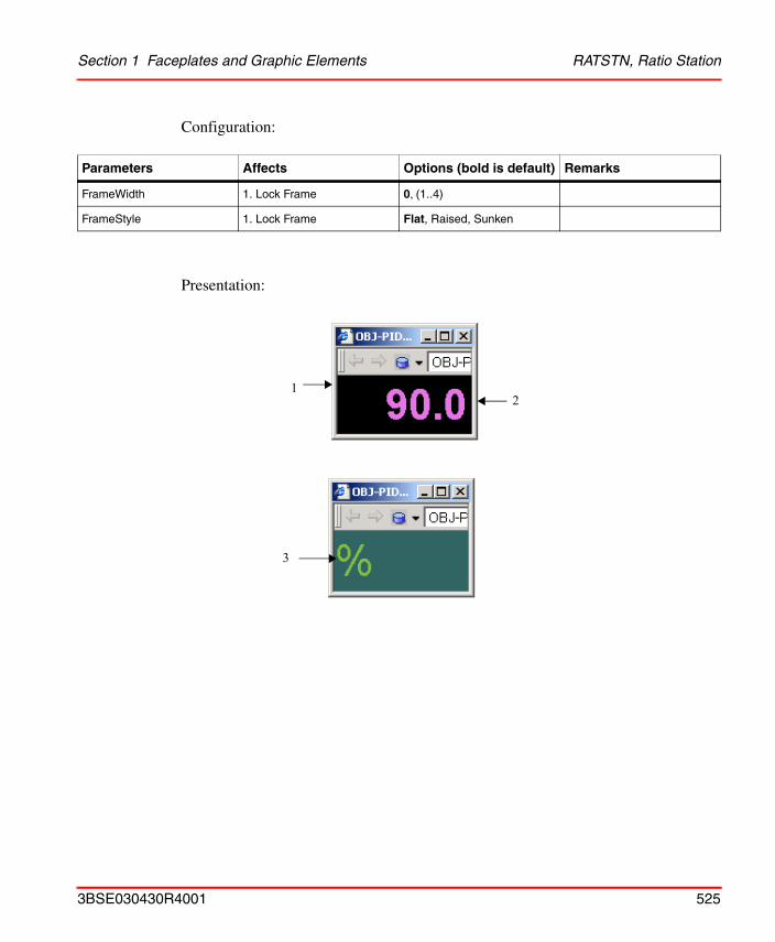
Section 1 Faceplates and Graphic Elements RATSTN, Ratio Station
Configuration:
Presentation:
Parameters Affects Options (bold is default) Remarks
FrameWidth 1. Lock Frame 0, (1..4)
FrameStyle 1. Lock Frame Flat, Raised, Sunken
12
3
3BSE030430R4001 525
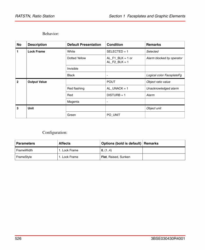
RATSTN, Ratio Station Section 1 Faceplates and Graphic Elements
Behavior:
Configuration:
No Description Default Presentation Condition Remarks
1 Lock Frame White SELECTED = 1 Selected
Dotted Yellow AL_F1_BLK = 1 orAL_F2_BLK = 1
Alarm blocked by operator
Invisible
Black - Logical color FaceplateFg
2 Output Value POUT Object ratio value
Red flashing AL_UNACK = 1 Unacknowledged alarm
Red DISTURB = 1 Alarm
Magenta -
3 Unit Object unit
Green PO_UNIT
Parameters Affects Options (bold is default) Remarks
FrameWidth 1. Lock Frame 0, (1..4)
FrameStyle 1. Lock Frame Flat, Raised, Sunken
526 3BSE030430R4001
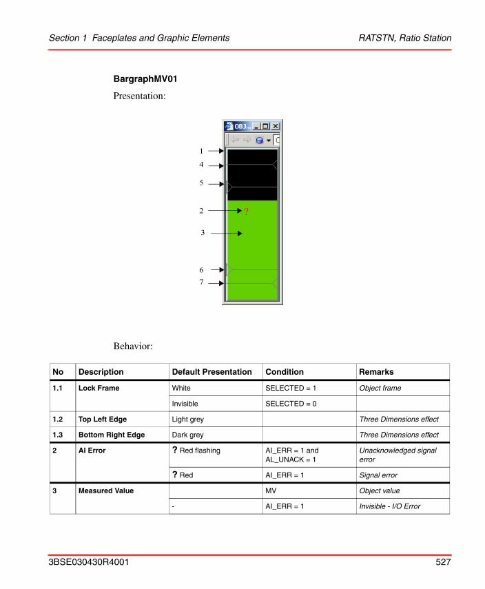
Section 1 Faceplates and Graphic Elements RATSTN, Ratio Station
BargraphMV01
Presentation:
Behavior:
No Description Default Presentation Condition Remarks
1.1 Lock Frame White SELECTED = 1 Object frame
Invisible SELECTED = 0
1.2 Top Left Edge Light grey Three Dimensions effect
1.3 Bottom Right Edge Dark grey Three Dimensions effect
2 AI Error ? Red flashing AI_ERR = 1 and AL_UNACK = 1
Unacknowledged signal error
? Red AI_ERR = 1 Signal error
3 Measured Value MV Object value
- AI_ERR = 1 Invisible - I/O Error
1
2
6
4
7
3
?
5
3BSE030430R4001 527
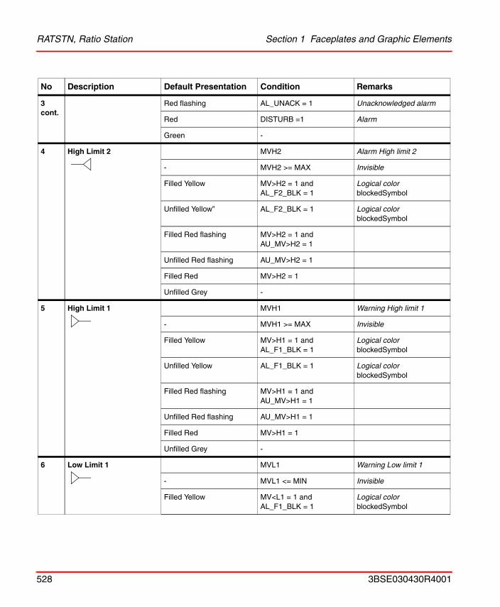
RATSTN, Ratio Station Section 1 Faceplates and Graphic Elements
3 cont.
Red flashing AL_UNACK = 1 Unacknowledged alarm
Red DISTURB =1 Alarm
Green -
4 High Limit 2 MVH2 Alarm High limit 2
- MVH2 >= MAX Invisible
Filled Yellow MV>H2 = 1 and AL_F2_BLK = 1
Logical colorblockedSymbol
Unfilled Yellow” AL_F2_BLK = 1 Logical colorblockedSymbol
Filled Red flashing MV>H2 = 1 and AU_MV>H2 = 1
Unfilled Red flashing AU_MV>H2 = 1
Filled Red MV>H2 = 1
Unfilled Grey -
5 High Limit 1 MVH1 Warning High limit 1
- MVH1 >= MAX Invisible
Filled Yellow MV>H1 = 1 and AL_F1_BLK = 1
Logical colorblockedSymbol
Unfilled Yellow AL_F1_BLK = 1 Logical colorblockedSymbol
Filled Red flashing MV>H1 = 1 and AU_MV>H1 = 1
Unfilled Red flashing AU_MV>H1 = 1
Filled Red MV>H1 = 1
Unfilled Grey -
6 Low Limit 1 MVL1 Warning Low limit 1
- MVL1 <= MIN Invisible
Filled Yellow MV<L1 = 1 and AL_F1_BLK = 1
Logical colorblockedSymbol
No Description Default Presentation Condition Remarks
528 3BSE030430R4001
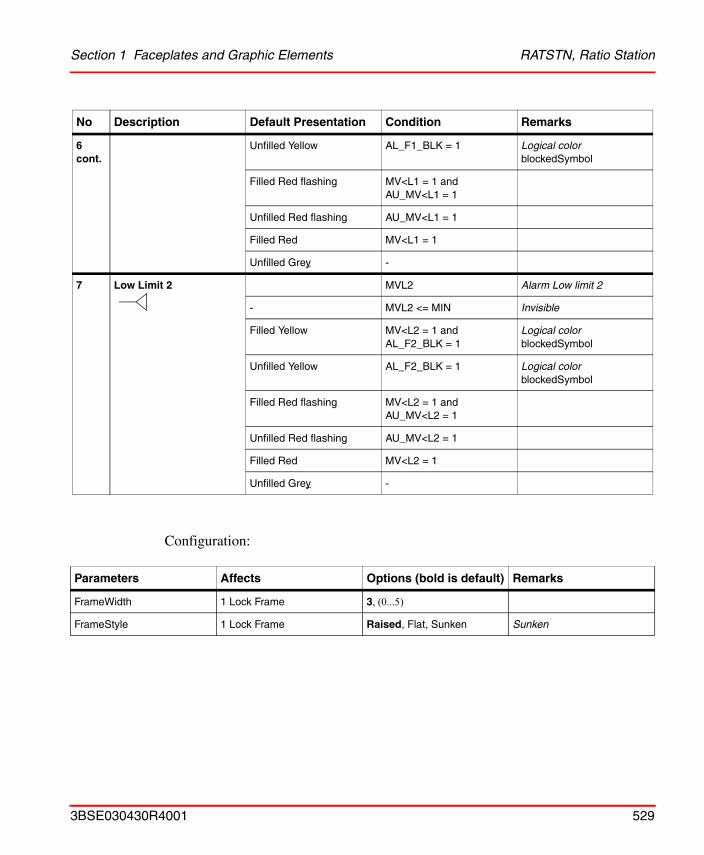
Section 1 Faceplates and Graphic Elements RATSTN, Ratio Station
Configuration:
6 cont.
Unfilled Yellow AL_F1_BLK = 1 Logical color blockedSymbol
Filled Red flashing MV<L1 = 1 and AU_MV<L1 = 1
Unfilled Red flashing AU_MV<L1 = 1
Filled Red MV<L1 = 1
Unfilled Grey -
7 Low Limit 2 MVL2 Alarm Low limit 2
- MVL2 <= MIN Invisible
Filled Yellow MV<L2 = 1 and AL_F2_BLK = 1
Logical color blockedSymbol
Unfilled Yellow AL_F2_BLK = 1 Logical color blockedSymbol
Filled Red flashing MV<L2 = 1 and AU_MV<L2 = 1
Unfilled Red flashing AU_MV<L2 = 1
Filled Red MV<L2 = 1
Unfilled Grey -
Parameters Affects Options (bold is default) Remarks
FrameWidth 1 Lock Frame 3, (0...5)
FrameStyle 1 Lock Frame Raised, Flat, Sunken Sunken
No Description Default Presentation Condition Remarks
3BSE030430R4001 529
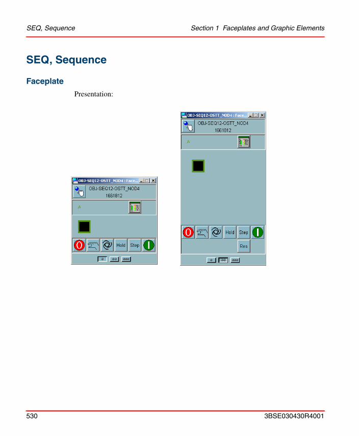
SEQ, Sequence Section 1 Faceplates and Graphic Elements
SEQ, Sequence
Faceplate
Presentation:
530 3BSE030430R4001
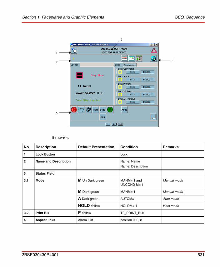
Section 1 Faceplates and Graphic Elements SEQ, Sequence
Behavior:
No Description Default Presentation Condition Remarks
1 Lock Button Lock
2 Name and Description Name: Name
Name: Description
3 Status Field
3.1 Mode M Un Dark green MANM= 1 andUNCOND M= 1
Manual mode
M Dark green MANM= 1 Manual mode
A Dark green AUTOM= 1 Auto mode
HOLD Yellow HOLDM= 1 Hold mode
3.2 Print Blk P Yellow TF_PRINT_BLK
4 Aspect links Alarm List position 0, 0, 8
1
3
5
4
2
3BSE030430R4001 531
SEQ, Sequence Section 1 Faceplates and Graphic Elements
4 cont.
Event List position 0, 0, 9
Object Display position 5, 5, 10
Object Type Help position 0, 0, 12
5 Start Start the Sequence Set START = 1
Stop Stop the Sequence Set START = 0
Man Set to manual mode Set MAN = 1
Auto Set to automatic mode Set MAN = 0
Hold Set to hold mode Set HOLD = 1
Step Step the Sequence one step
Set STEP = 1
Res Reset the Sequence to initial values
Set RESET = 1
Jump Jump to step JPOSN_OUT Set JUMP = 1
No Description Default Presentation Condition Remarks
532 3BSE030430R4001
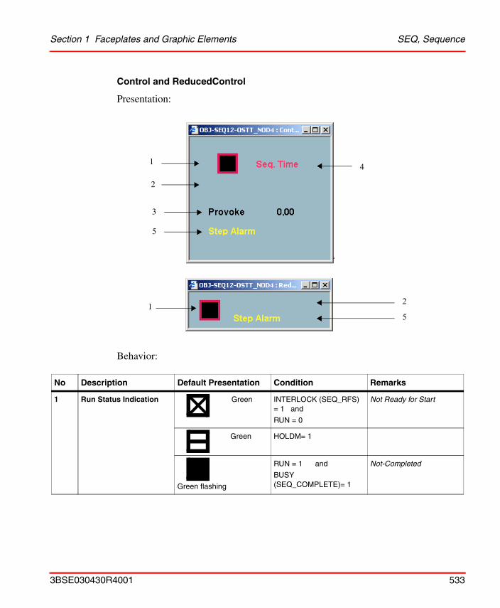
Section 1 Faceplates and Graphic Elements SEQ, Sequence
Control and ReducedControl
Presentation:
Behavior:
No Description Default Presentation Condition Remarks
1 Run Status Indication Green INTERLOCK (SEQ_RFS) = 1 and
RUN = 0
Not Ready for Start
Green HOLDM= 1
Green flashing
RUN = 1 and
BUSY (SEQ_COMPLETE)= 1
Not-Completed
41
3
5
2
215
3BSE030430R4001 533
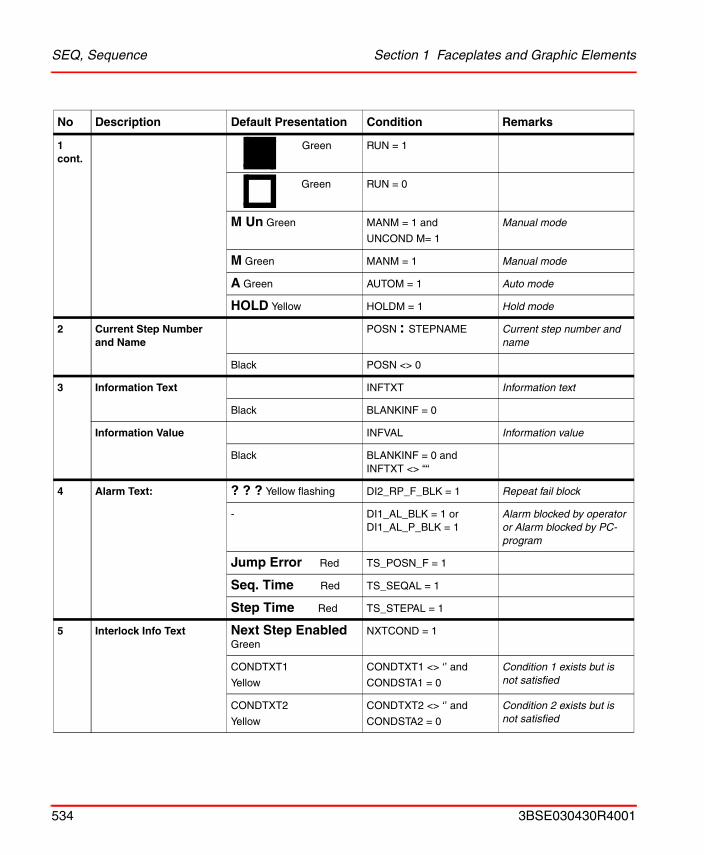
SEQ, Sequence Section 1 Faceplates and Graphic Elements
1 cont.
Green RUN = 1
Green RUN = 0
M Un Green MANM = 1 and
UNCOND M= 1
Manual mode
M Green MANM = 1 Manual mode
A Green AUTOM = 1 Auto mode
HOLD Yellow HOLDM = 1 Hold mode
2 Current Step Number and Name
POSN : STEPNAME Current step number and name
Black POSN <> 0
3 Information Text INFTXT Information text
Black BLANKINF = 0
Information Value INFVAL Information value
Black BLANKINF = 0 and INFTXT <> ““
4 Alarm Text: ? ? ? Yellow flashing DI2_RP_F_BLK = 1 Repeat fail block
- DI1_AL_BLK = 1 orDI1_AL_P_BLK = 1
Alarm blocked by operator or Alarm blocked by PC-program
Jump Error Red TS_POSN_F = 1
Seq. Time Red TS_SEQAL = 1
Step Time Red TS_STEPAL = 1
5 Interlock Info Text Next Step Enabled Green
NXTCOND = 1
CONDTXT1
Yellow
CONDTXT1 <> ‘’ and
CONDSTA1 = 0
Condition 1 exists but is not satisfied
CONDTXT2
Yellow
CONDTXT2 <> ‘’ and
CONDSTA2 = 0
Condition 2 exists but is not satisfied
No Description Default Presentation Condition Remarks
534 3BSE030430R4001
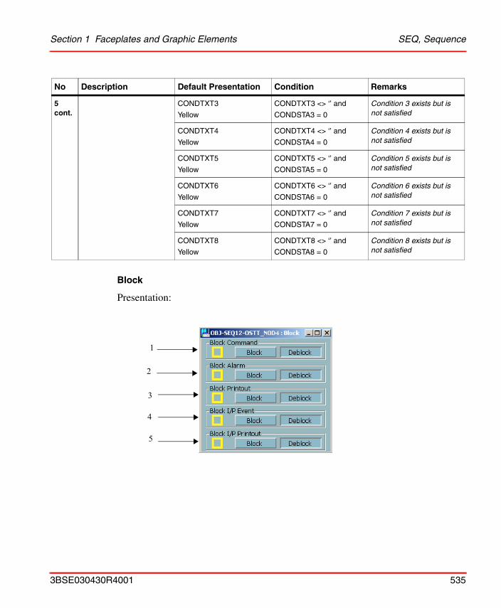
Section 1 Faceplates and Graphic Elements SEQ, Sequence
Block
Presentation:
5 cont.
CONDTXT3
Yellow
CONDTXT3 <> ‘’ and
CONDSTA3 = 0
Condition 3 exists but is not satisfied
CONDTXT4
Yellow
CONDTXT4 <> ‘’ and
CONDSTA4 = 0
Condition 4 exists but is not satisfied
CONDTXT5
Yellow
CONDTXT5 <> ‘’ and
CONDSTA5 = 0
Condition 5 exists but is not satisfied
CONDTXT6
Yellow
CONDTXT6 <> ‘’ and
CONDSTA6 = 0
Condition 6 exists but is not satisfied
CONDTXT7
Yellow
CONDTXT7 <> ‘’ and
CONDSTA7 = 0
Condition 7 exists but is not satisfied
CONDTXT8
Yellow
CONDTXT8 <> ‘’ and
CONDSTA8 = 0
Condition 8 exists but is not satisfied
No Description Default Presentation Condition Remarks
1
2
3
5
4
3BSE030430R4001 535
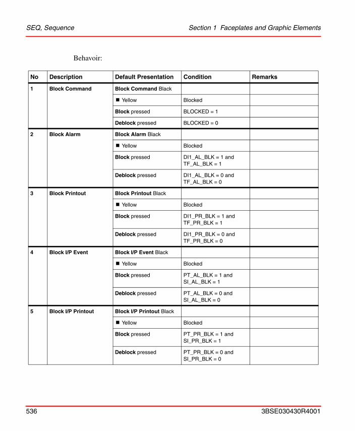
SEQ, Sequence Section 1 Faceplates and Graphic Elements
Behavoir:
No Description Default Presentation Condition Remarks
1 Block Command Block Command Black
! Yellow Blocked
Block pressed BLOCKED = 1
Deblock pressed BLOCKED = 0
2 Block Alarm Block Alarm Black
! Yellow Blocked
Block pressed DI1_AL_BLK = 1 and TF_AL_BLK = 1
Deblock pressed DI1_AL_BLK = 0 and TF_AL_BLK = 0
3 Block Printout Block Printout Black
! Yellow Blocked
Block pressed DI1_PR_BLK = 1 and TF_PR_BLK = 1
Deblock pressed DI1_PR_BLK = 0 and TF_PR_BLK = 0
4 Block I/P Event Block I/P Event Black
! Yellow Blocked
Block pressed PT_AL_BLK = 1 and SI_AL_BLK = 1
Deblock pressed PT_AL_BLK = 0 and SI_AL_BLK = 0
5 Block I/P Printout Block I/P Printout Black
! Yellow Blocked
Block pressed PT_PR_BLK = 1 and SI_PR_BLK = 1
Deblock pressed PT_PR_BLK = 0 and SI_PR_BLK = 0
536 3BSE030430R4001
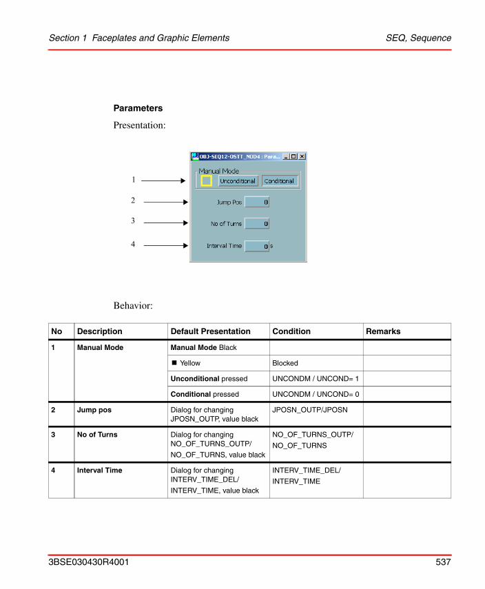
Section 1 Faceplates and Graphic Elements SEQ, Sequence
Parameters
Presentation:
Behavior:
No Description Default Presentation Condition Remarks
1 Manual Mode Manual Mode Black
! Yellow Blocked
Unconditional pressed UNCONDM / UNCOND= 1
Conditional pressed UNCONDM / UNCOND= 0
2 Jump pos Dialog for changing JPOSN_OUTP, value black
JPOSN_OUTP/JPOSN
3 No of Turns Dialog for changing NO_OF_TURNS_OUTP/
NO_OF_TURNS, value black
NO_OF_TURNS_OUTP/
NO_OF_TURNS
4 Interval Time Dialog for changing INTERV_TIME_DEL/
INTERV_TIME, value black
INTERV_TIME_DEL/
INTERV_TIME
1
2
3
4
3BSE030430R4001 537
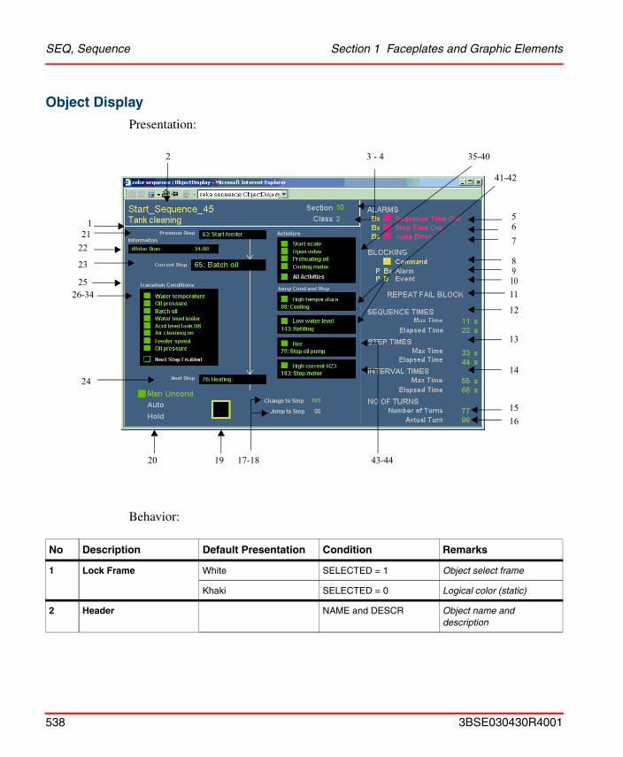
SEQ, Sequence Section 1 Faceplates and Graphic Elements
Object Display
Presentation:
Behavior:
No Description Default Presentation Condition Remarks
1 Lock Frame White SELECTED = 1 Object select frame
Khaki SELECTED = 0 Logical color (static)
2 Header NAME and DESCR Object name and description
2
5
11
12
13
14
15
67
89
3 - 4
10
16
17-181920
24
121
22
23
2526-34
35-40
41-42
43-44
538 3BSE030430R4001
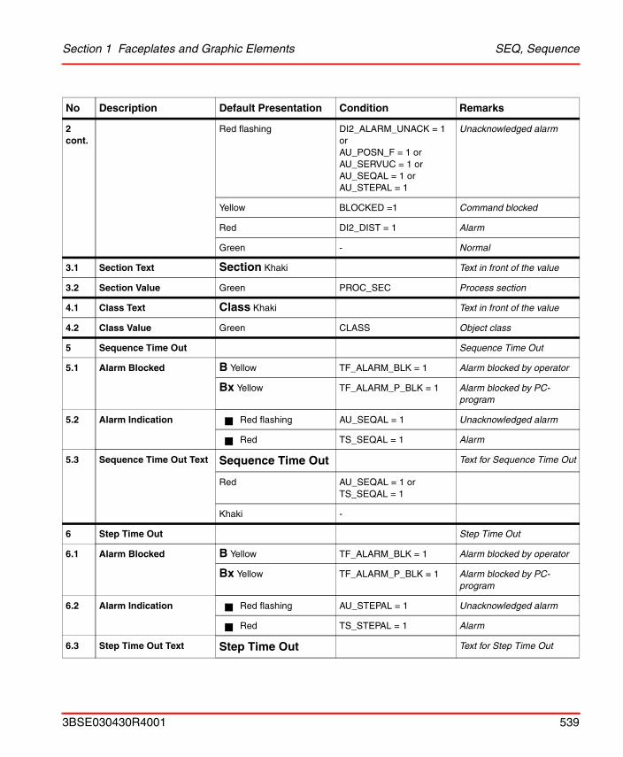
Section 1 Faceplates and Graphic Elements SEQ, Sequence
2 cont.
Red flashing DI2_ALARM_UNACK = 1 orAU_POSN_F = 1 orAU_SERVUC = 1 orAU_SEQAL = 1 orAU_STEPAL = 1
Unacknowledged alarm
Yellow BLOCKED =1 Command blocked
Red DI2_DIST = 1 Alarm
Green - Normal
3.1 Section Text Section Khaki Text in front of the value
3.2 Section Value Green PROC_SEC Process section
4.1 Class Text Class Khaki Text in front of the value
4.2 Class Value Green CLASS Object class
5 Sequence Time Out Sequence Time Out
5.1 Alarm Blocked B Yellow TF_ALARM_BLK = 1 Alarm blocked by operator
Bx Yellow TF_ALARM_P_BLK = 1 Alarm blocked by PC-program
5.2 Alarm Indication Red flashing AU_SEQAL = 1 Unacknowledged alarm
Red TS_SEQAL = 1 Alarm
5.3 Sequence Time Out Text Sequence Time Out Text for Sequence Time Out
Red AU_SEQAL = 1 or TS_SEQAL = 1
Khaki -
6 Step Time Out Step Time Out
6.1 Alarm Blocked B Yellow TF_ALARM_BLK = 1 Alarm blocked by operator
Bx Yellow TF_ALARM_P_BLK = 1 Alarm blocked by PC-program
6.2 Alarm Indication Red flashing AU_STEPAL = 1 Unacknowledged alarm
Red TS_STEPAL = 1 Alarm
6.3 Step Time Out Text Step Time Out Text for Step Time Out
No Description Default Presentation Condition Remarks
3BSE030430R4001 539
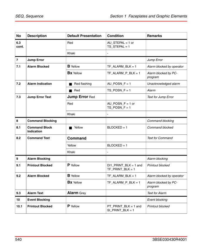
SEQ, Sequence Section 1 Faceplates and Graphic Elements
6.3 cont.
Red AU_STEPAL = 1 orTS_STEPAL = 1
Khaki -
7 Jump Error Jump Error
7.1 Alarm Blocked B Yellow TF_ALARM_BLK = 1 Alarm blocked by operator
Bx Yellow TF_ALARM_P_BLK = 1 Alarm blocked by PC-program
7.2 Alarm Indication Red flashing AU_POSN_F = 1 Unacknowledged alarm
Red TS_POSN_F = 1 Alarm
7.3 Jump Error Text Jump Error Red Text for Jump Error
Red AU_POSN_F = 1 orTS_POSN_F = 1
Khaki -
8 Command Blocking Command blocking
8.1 Command Block Indication
Yellow BLOCKED = 1 Command blocked
8.2 Command Text Command Text for Command
Yellow BLOCKED = 1
Khaki -
9 Alarm Blocking Alarm blocking
9.1 Printout Blocked P Yellow DI1_PRINT_BLK = 1 andTF_PRINT_BLK = 1
Printout blocked
9.2 Alarm Blocked B Yellow TF_ALARM_BLK = 1 Alarm blocked by operator
Bx Yellow TF_ALARM_P_BLK = 1 Alarm blocked by PC-program
9.3 Alarm Text Alarm Grey Text for Alarm
10 Event Blocking Event blocking
10.1 Printout Blocked P Yellow PT_PRINT_BLK = 1 andSI_PRINT_BLK = 1
Printout blocked
No Description Default Presentation Condition Remarks
540 3BSE030430R4001
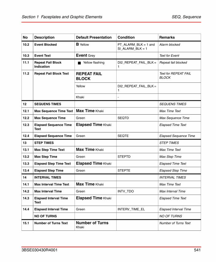
Section 1 Faceplates and Graphic Elements SEQ, Sequence
10.2 Event Blocked B Yellow PT_ALARM_BLK = 1 andSI_ALARM_BLK = 1
Alarm blocked
10.3 Event Text Event Grey Text for Event
11.1 Repeat Fail Block Indication
Yellow flashing DI2_REPEAT_FAIL_BLK = 1
Repeat fail blocked
11.2 Repeat Fail Block Text REPEAT FAIL BLOCK
Text for REPEAT FAIL BLOCK
Yellow DI2_REPEAT_FAIL_BLK = 1
Khaki -
12 SEQUENS TIMES SEQUENS TIMES
12.1 Max Sequence Time Text Max Time Khaki Max Time Text
12.2 Max Sequence Time Green SEQTD Max Sequence Time
12.3 Elapsed Sequence Time Text
Elapsed Time Khaki Elapsed Time Text
12.4 Elapsed Sequence Time Green SEQTE Elapsed Sequence Time
13 STEP TIMES STEP TIMES
13.1 Max Step Time Text Max Time Khaki Max Time Text
13.2 Max Step Time Green STEPTD Max Step Time
13.3 Elapsed Step Time Text Elapsed Time Khaki Elapsed Time Text
13.4 Elapsed Step Time Green STEPTE Elapsed Step Time
14 INTERVAL TIMES INTERVAL TIMES
14.1 Max Interval Time Text Max Time Khaki Max Time Text
14.2 Max Interval Time Green INTV_TDO Max Interval Time
14.3 Elapsed Interval Time Text
Elapsed Time Khaki Elapsed Time Text
14.4 Elapsed Interval Time Green INTERV_TIME_EL Elapsed Interval Time
NO OF TURNS NO OF TURNS
15.1 Number of Turns Text Number of Turns Khaki
Number of Turns Text
No Description Default Presentation Condition Remarks
3BSE030430R4001 541
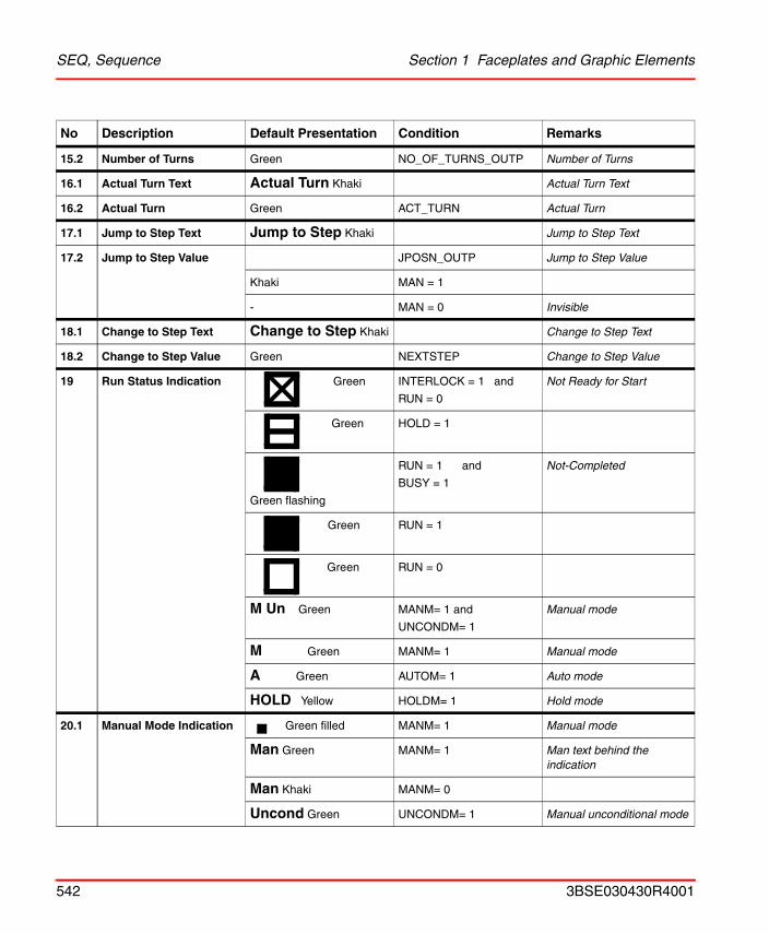
SEQ, Sequence Section 1 Faceplates and Graphic Elements
15.2 Number of Turns Green NO_OF_TURNS_OUTP Number of Turns
16.1 Actual Turn Text Actual Turn Khaki Actual Turn Text
16.2 Actual Turn Green ACT_TURN Actual Turn
17.1 Jump to Step Text Jump to Step Khaki Jump to Step Text
17.2 Jump to Step Value JPOSN_OUTP Jump to Step Value
Khaki MAN = 1
- MAN = 0 Invisible
18.1 Change to Step Text Change to Step Khaki Change to Step Text
18.2 Change to Step Value Green NEXTSTEP Change to Step Value
19 Run Status Indication Green INTERLOCK = 1 and
RUN = 0
Not Ready for Start
Green HOLD = 1
Green flashing
RUN = 1 and
BUSY = 1
Not-Completed
Green RUN = 1
Green RUN = 0
M Un Green MANM= 1 and
UNCONDM= 1
Manual mode
M Green MANM= 1 Manual mode
A Green AUTOM= 1 Auto mode
HOLD Yellow HOLDM= 1 Hold mode
20.1 Manual Mode Indication Green filled MANM= 1 Manual mode
Man Green MANM= 1 Man text behind the indication
Man Khaki MANM= 0
Uncond Green UNCONDM= 1 Manual unconditional mode
No Description Default Presentation Condition Remarks
542 3BSE030430R4001
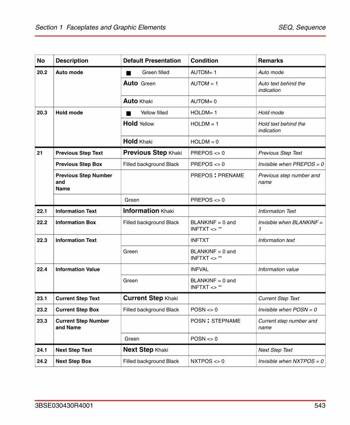
Section 1 Faceplates and Graphic Elements SEQ, Sequence
20.2 Auto mode Green filled AUTOM= 1 Auto mode
Auto Green AUTOM = 1 Auto text behind the indication
Auto Khaki AUTOM= 0
20.3 Hold mode Yellow filled HOLDM= 1 Hold mode
Hold Yellow HOLDM = 1 Hold text behind the indication
Hold Khaki HOLDM = 0
21 Previous Step Text Previous Step Khaki PREPOS <> 0 Previous Step Text
Previous Step Box Filled background Black PREPOS <> 0 Invisible when PREPOS = 0
Previous Step Number andName
PREPOS : PRENAME Previous step number and name
Green PREPOS <> 0
22.1 Information Text Information Khaki Information Text
22.2 Information Box Filled background Black BLANKINF = 0 and INFTXT <> ““
Invisible when BLANKINF = 1
22.3 Information Text INFTXT Information text
Green BLANKINF = 0 and INFTXT <> ““
22.4 Information Value INFVAL Information value
Green BLANKINF = 0 and INFTXT <> ““
23.1 Current Step Text Current Step Khaki Current Step Text
23.2 Current Step Box Filled background Black POSN <> 0 Invisible when POSN = 0
23.3 Current Step Number and Name
POSN : STEPNAME Current step number and name
Green POSN <> 0
24.1 Next Step Text Next Step Khaki Next Step Text
24.2 Next Step Box Filled background Black NXTPOS <> 0 Invisible when NXTPOS = 0
No Description Default Presentation Condition Remarks
3BSE030430R4001 543
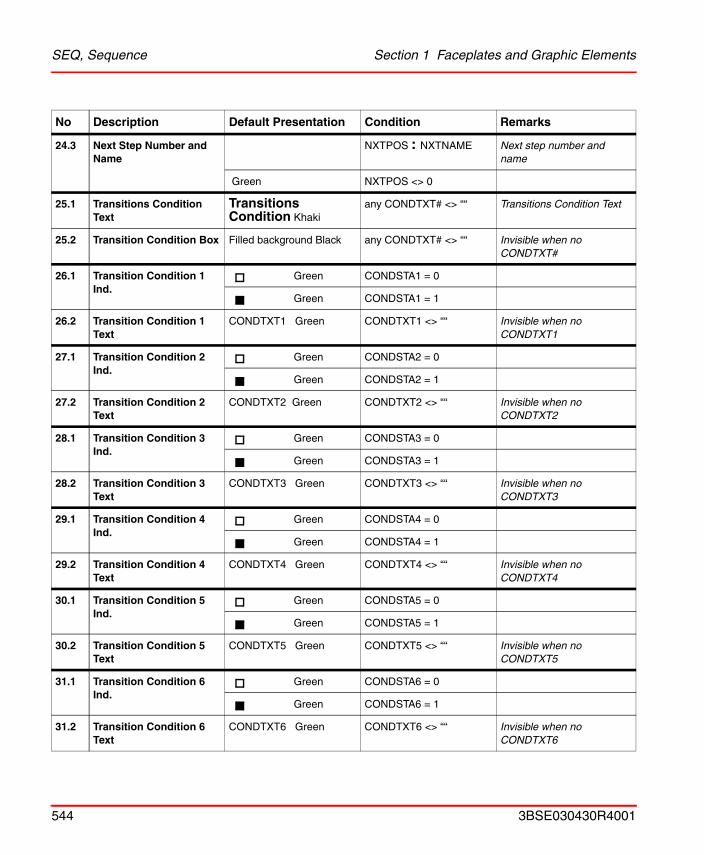
SEQ, Sequence Section 1 Faceplates and Graphic Elements
24.3 Next Step Number and Name
NXTPOS : NXTNAME Next step number and name
Green NXTPOS <> 0
25.1 Transitions Condition Text
Transitions Condition Khaki
any CONDTXT# <> ““ Transitions Condition Text
25.2 Transition Condition Box Filled background Black any CONDTXT# <> ““ Invisible when no CONDTXT#
26.1 Transition Condition 1 Ind.
Green CONDSTA1 = 0
Green CONDSTA1 = 1
26.2 Transition Condition 1 Text
CONDTXT1 Green CONDTXT1 <> ““ Invisible when no CONDTXT1
27.1 Transition Condition 2 Ind.
Green CONDSTA2 = 0
Green CONDSTA2 = 1
27.2 Transition Condition 2 Text
CONDTXT2 Green CONDTXT2 <> ““ Invisible when no CONDTXT2
28.1 Transition Condition 3 Ind.
Green CONDSTA3 = 0
Green CONDSTA3 = 1
28.2 Transition Condition 3 Text
CONDTXT3 Green CONDTXT3 <> ““ Invisible when no CONDTXT3
29.1 Transition Condition 4 Ind.
Green CONDSTA4 = 0
Green CONDSTA4 = 1
29.2 Transition Condition 4 Text
CONDTXT4 Green CONDTXT4 <> ““ Invisible when no CONDTXT4
30.1 Transition Condition 5 Ind.
Green CONDSTA5 = 0
Green CONDSTA5 = 1
30.2 Transition Condition 5 Text
CONDTXT5 Green CONDTXT5 <> ““ Invisible when no CONDTXT5
31.1 Transition Condition 6 Ind.
Green CONDSTA6 = 0
Green CONDSTA6 = 1
31.2 Transition Condition 6 Text
CONDTXT6 Green CONDTXT6 <> ““ Invisible when no CONDTXT6
No Description Default Presentation Condition Remarks
544 3BSE030430R4001
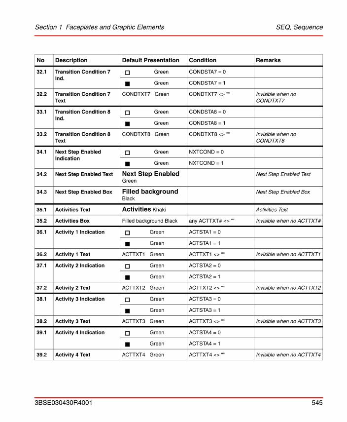
Section 1 Faceplates and Graphic Elements SEQ, Sequence
32.1 Transition Condition 7 Ind.
Green CONDSTA7 = 0
Green CONDSTA7 = 1
32.2 Transition Condition 7 Text
CONDTXT7 Green CONDTXT7 <> ““ Invisible when no CONDTXT7
33.1 Transition Condition 8 Ind.
Green CONDSTA8 = 0
Green CONDSTA8 = 1
33.2 Transition Condition 8 Text
CONDTXT8 Green CONDTXT8 <> ““ Invisible when no CONDTXT8
34.1 Next Step Enabled Indication
Green NXTCOND = 0
Green NXTCOND = 1
34.2 Next Step Enabled Text Next Step Enabled Green
Next Step Enabled Text
34.3 Next Step Enabled Box Filled background Black
Next Step Enabled Box
35.1 Activities Text Activities Khaki Activities Text
35.2 Activities Box Filled background Black any ACTTXT# <> ““ Invisible when no ACTTXT#
36.1 Activity 1 Indication Green ACTSTA1 = 0
Green ACTSTA1 = 1
36.2 Activity 1 Text ACTTXT1 Green ACTTXT1 <> ““ Invisible when no ACTTXT1
37.1 Activity 2 Indication Green ACTSTA2 = 0
Green ACTSTA2 = 1
37.2 Activity 2 Text ACTTXT2 Green ACTTXT2 <> ““ Invisible when no ACTTXT2
38.1 Activity 3 Indication Green ACTSTA3 = 0
Green ACTSTA3 = 1
38.2 Activity 3 Text ACTTXT3 Green ACTTXT3 <> ““ Invisible when no ACTTXT3
39.1 Activity 4 Indication Green ACTSTA4 = 0
Green ACTSTA4 = 1
39.2 Activity 4 Text ACTTXT4 Green ACTTXT4 <> ““ Invisible when no ACTTXT4
No Description Default Presentation Condition Remarks
3BSE030430R4001 545
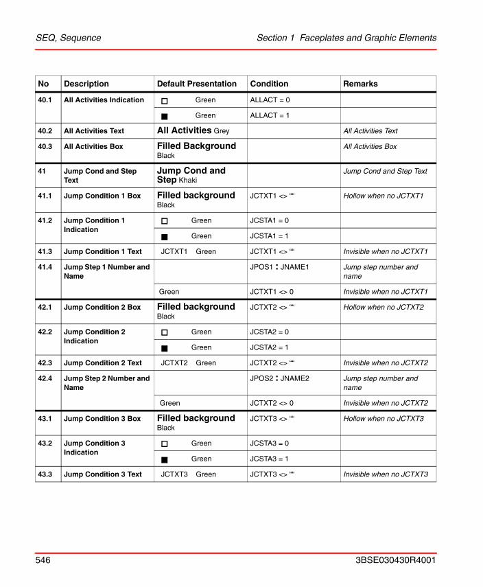
SEQ, Sequence Section 1 Faceplates and Graphic Elements
40.1 All Activities Indication Green ALLACT = 0
Green ALLACT = 1
40.2 All Activities Text All Activities Grey All Activities Text
40.3 All Activities Box Filled Background Black
All Activities Box
41 Jump Cond and Step Text
Jump Cond and Step Khaki
Jump Cond and Step Text
41.1 Jump Condition 1 Box Filled background Black
JCTXT1 <> ““ Hollow when no JCTXT1
41.2 Jump Condition 1 Indication
Green JCSTA1 = 0
Green JCSTA1 = 1
41.3 Jump Condition 1 Text JCTXT1 Green JCTXT1 <> ““ Invisible when no JCTXT1
41.4 Jump Step 1 Number and Name
JPOS1 : JNAME1 Jump step number and name
Green JCTXT1 <> 0 Invisible when no JCTXT1
42.1 Jump Condition 2 Box Filled background Black
JCTXT2 <> ““ Hollow when no JCTXT2
42.2 Jump Condition 2 Indication
Green JCSTA2 = 0
Green JCSTA2 = 1
42.3 Jump Condition 2 Text JCTXT2 Green JCTXT2 <> ““ Invisible when no JCTXT2
42.4 Jump Step 2 Number and Name
JPOS2 : JNAME2 Jump step number and name
Green JCTXT2 <> 0 Invisible when no JCTXT2
43.1 Jump Condition 3 Box Filled background Black
JCTXT3 <> ““ Hollow when no JCTXT3
43.2 Jump Condition 3 Indication
Green JCSTA3 = 0
Green JCSTA3 = 1
43.3 Jump Condition 3 Text JCTXT3 Green JCTXT3 <> ““ Invisible when no JCTXT3
No Description Default Presentation Condition Remarks
546 3BSE030430R4001
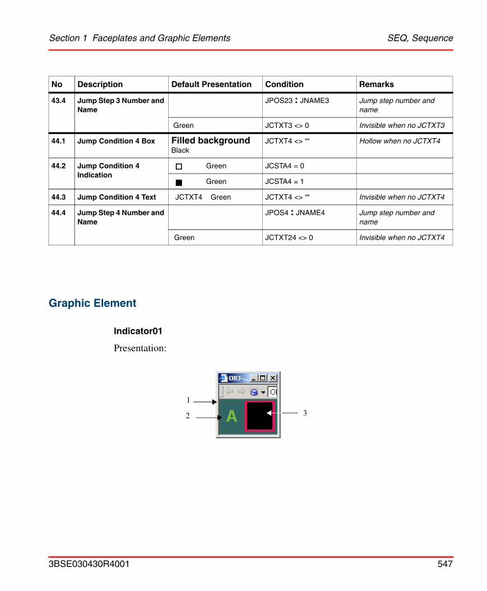
Section 1 Faceplates and Graphic Elements SEQ, Sequence
Graphic Element
Indicator01
Presentation:
43.4 Jump Step 3 Number and Name
JPOS23 : JNAME3 Jump step number and name
Green JCTXT3 <> 0 Invisible when no JCTXT3
44.1 Jump Condition 4 Box Filled background Black
JCTXT4 <> ““ Hollow when no JCTXT4
44.2 Jump Condition 4 Indication
Green JCSTA4 = 0
Green JCSTA4 = 1
44.3 Jump Condition 4 Text JCTXT4 Green JCTXT4 <> ““ Invisible when no JCTXT4
44.4 Jump Step 4 Number and Name
JPOS4 : JNAME4 Jump step number and name
Green JCTXT24 <> 0 Invisible when no JCTXT4
No Description Default Presentation Condition Remarks
2 31
3BSE030430R4001 547
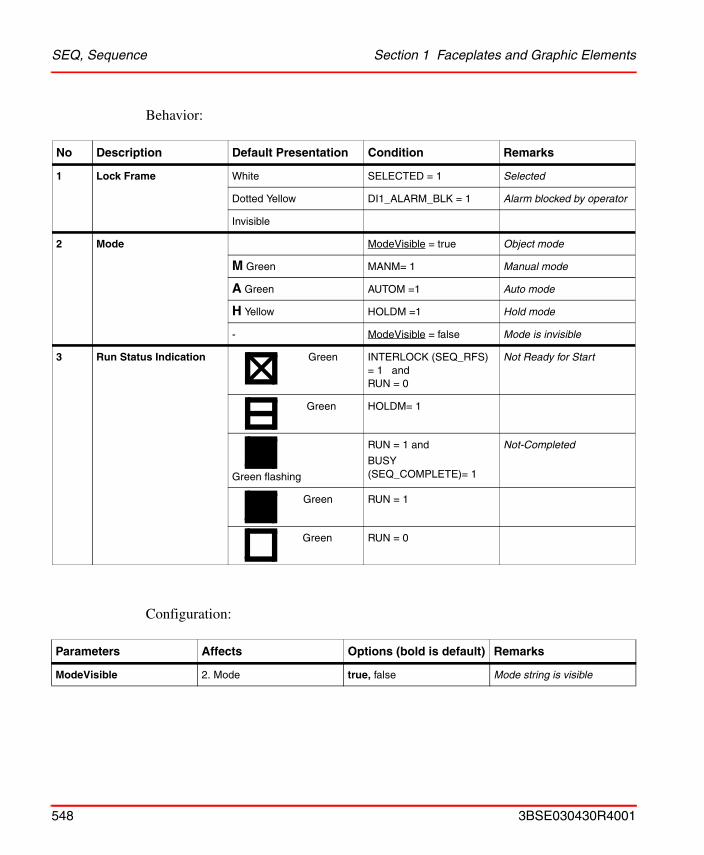
SEQ, Sequence Section 1 Faceplates and Graphic Elements
Behavior:
Configuration:
No Description Default Presentation Condition Remarks
1 Lock Frame White SELECTED = 1 Selected
Dotted Yellow DI1_ALARM_BLK = 1 Alarm blocked by operator
Invisible
2 Mode ModeVisible = true Object mode
M Green MANM= 1 Manual mode
A Green AUTOM =1 Auto mode
H Yellow HOLDM =1 Hold mode
- ModeVisible = false Mode is invisible
3 Run Status Indication Green INTERLOCK (SEQ_RFS) = 1 andRUN = 0
Not Ready for Start
Green HOLDM= 1
Green flashing
RUN = 1 and
BUSY (SEQ_COMPLETE)= 1
Not-Completed
Green RUN = 1
Green RUN = 0
Parameters Affects Options (bold is default) Remarks
ModeVisible 2. Mode true, false Mode string is visible
548 3BSE030430R4001
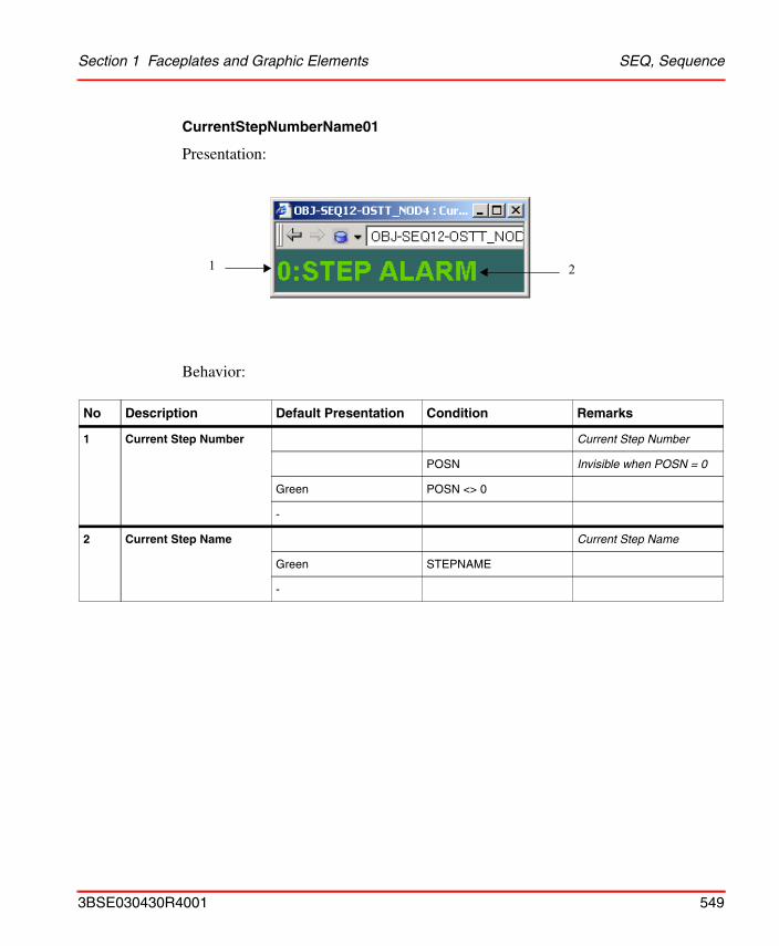
Section 1 Faceplates and Graphic Elements SEQ, Sequence
CurrentStepNumberName01
Presentation:
Behavior:
No Description Default Presentation Condition Remarks
1 Current Step Number Current Step Number
POSN Invisible when POSN = 0
Green POSN <> 0
-
2 Current Step Name Current Step Name
Green STEPNAME
-
21
3BSE030430R4001 549
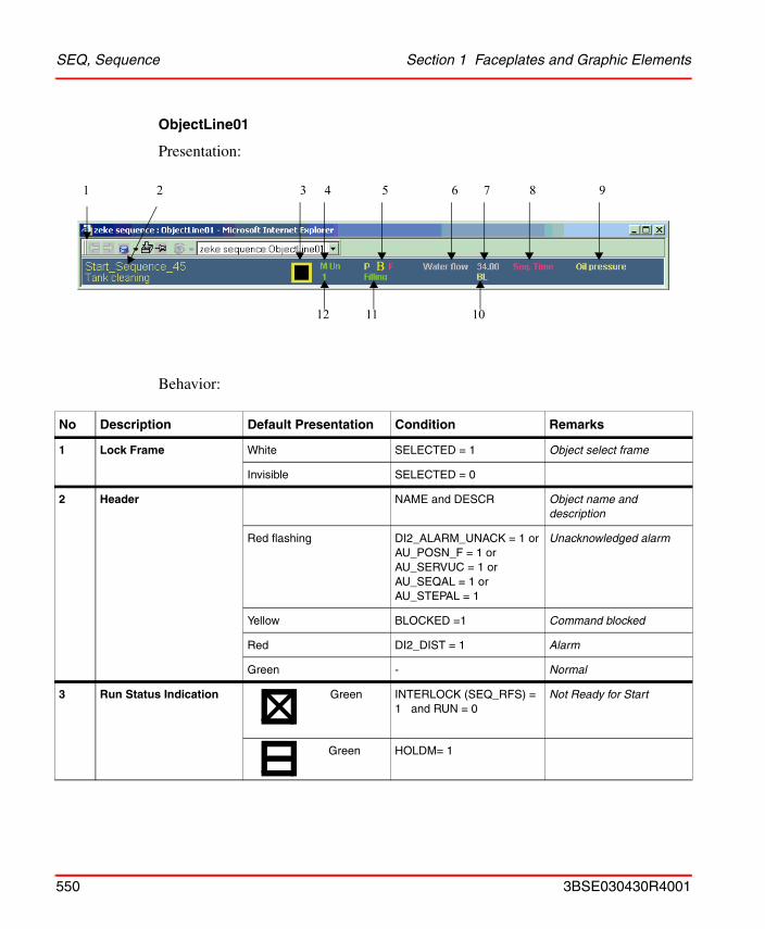
SEQ, Sequence Section 1 Faceplates and Graphic Elements
ObjectLine01
Presentation:
Behavior:
No Description Default Presentation Condition Remarks
1 Lock Frame White SELECTED = 1 Object select frame
Invisible SELECTED = 0
2 Header NAME and DESCR Object name and description
Red flashing DI2_ALARM_UNACK = 1 orAU_POSN_F = 1 orAU_SERVUC = 1 orAU_SEQAL = 1 orAU_STEPAL = 1
Unacknowledged alarm
Yellow BLOCKED =1 Command blocked
Red DI2_DIST = 1 Alarm
Green - Normal
3 Run Status Indication Green INTERLOCK (SEQ_RFS) = 1 and RUN = 0
Not Ready for Start
Green HOLDM= 1
B
1 2 3 4 5 6 7 8 9
11 1012
550 3BSE030430R4001
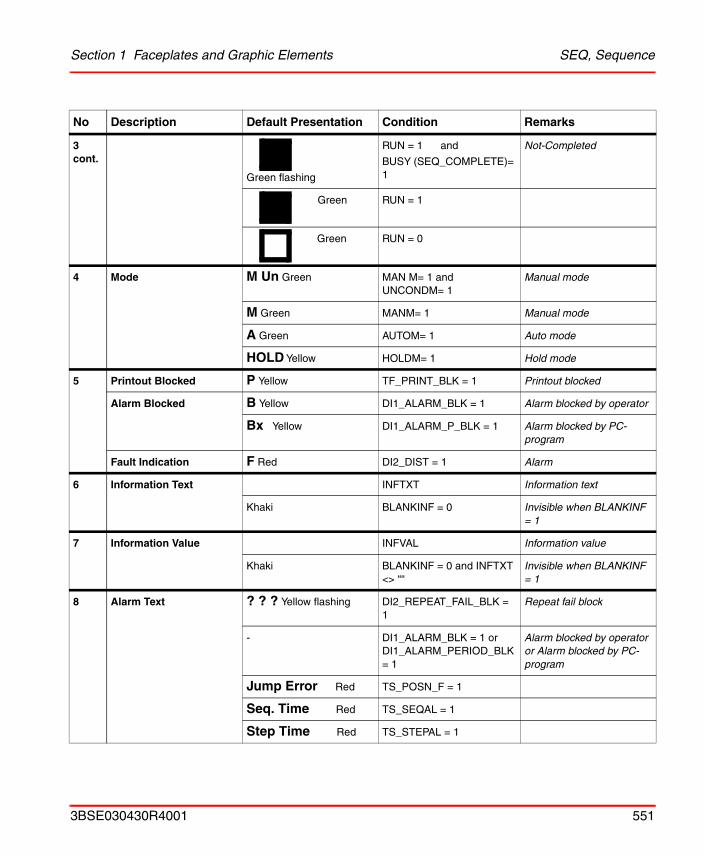
Section 1 Faceplates and Graphic Elements SEQ, Sequence
3 cont.
Green flashing
RUN = 1 and
BUSY (SEQ_COMPLETE)= 1
Not-Completed
Green RUN = 1
Green RUN = 0
4 Mode M Un Green MAN M= 1 andUNCONDM= 1
Manual mode
M Green MANM= 1 Manual mode
A Green AUTOM= 1 Auto mode
HOLD Yellow HOLDM= 1 Hold mode
5 Printout Blocked P Yellow TF_PRINT_BLK = 1 Printout blocked
Alarm Blocked B Yellow DI1_ALARM_BLK = 1 Alarm blocked by operator
Bx Yellow DI1_ALARM_P_BLK = 1 Alarm blocked by PC-program
Fault Indication F Red DI2_DIST = 1 Alarm
6 Information Text INFTXT Information text
Khaki BLANKINF = 0 Invisible when BLANKINF = 1
7 Information Value INFVAL Information value
Khaki BLANKINF = 0 and INFTXT <> ““
Invisible when BLANKINF = 1
8 Alarm Text ? ? ? Yellow flashing DI2_REPEAT_FAIL_BLK = 1
Repeat fail block
- DI1_ALARM_BLK = 1 orDI1_ALARM_PERIOD_BLK = 1
Alarm blocked by operator or Alarm blocked by PC-program
Jump Error Red TS_POSN_F = 1
Seq. Time Red TS_SEQAL = 1
Step Time Red TS_STEPAL = 1
No Description Default Presentation Condition Remarks
3BSE030430R4001 551
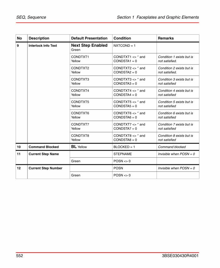
SEQ, Sequence Section 1 Faceplates and Graphic Elements
9 Interlock Info Text Next Step Enabled Green
NXTCOND = 1
CONDTXT1Yellow
CONDTXT1 <> ‘’ andCONDSTA1 = 0
Condition 1 exists but is not satisfied.
CONDTXT2Yellow
CONDTXT2 <> ‘’ andCONDSTA2 = 0
Condition 2 exists but is not satisfied.
CONDTXT3Yellow
CONDTXT3 <> ‘’ and CONDSTA3 = 0
Condition 3 exists but is not satisfied
CONDTXT4Yellow
CONDTXT4 <> ‘’ and CONDSTA4 = 0
Condition 4 exists but is not satisfied
CONDTXT5Yellow
CONDTXT5 <> ‘’ and CONDSTA5 = 0
Condition 5 exists but is not satisfied
CONDTXT6Yellow
CONDTXT6 <> ‘’ and CONDSTA6 = 0
Condition 6 exists but is not satisfied
CONDTXT7Yellow
CONDTXT7 <> ‘’ and CONDSTA7 = 0
Condition 7 exists but is not satisfied
CONDTXT8Yellow
CONDTXT8 <> ‘’ and CONDSTA8 = 0
Condition 8 exists but is not satisfied
10 Command Blocked BL Yellow BLOCKED = 1 Command blocked
11 Current Step Name STEPNAME Invisible when POSN = 0
Green POSN <> 0
12 Current Step Number POSN Invisible when POSN = 0
Green POSN <> 0
No Description Default Presentation Condition Remarks
552 3BSE030430R4001
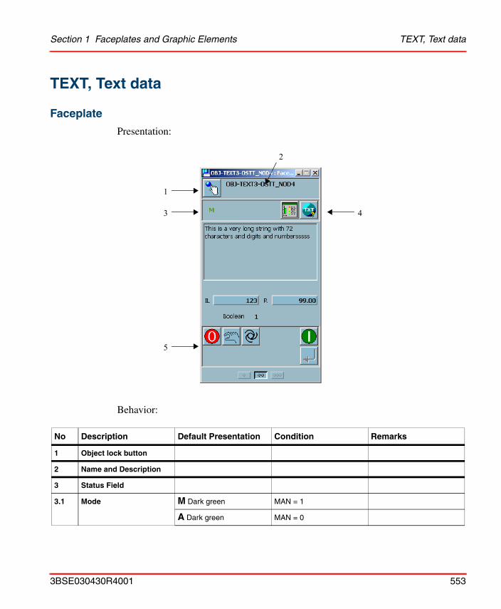
Section 1 Faceplates and Graphic Elements TEXT, Text data
TEXT, Text data
Faceplate
Presentation:
Behavior:
No Description Default Presentation Condition Remarks
1 Object lock button
2 Name and Description
3 Status Field
3.1 Mode M Dark green MAN = 1
A Dark green MAN = 0
1
3
5
4
2
3BSE030430R4001 553
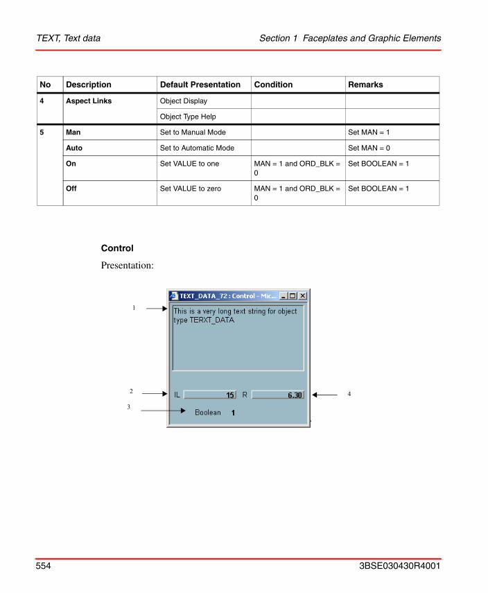
TEXT, Text data Section 1 Faceplates and Graphic Elements
Control
Presentation:
4 Aspect Links Object Display
Object Type Help
5 Man Set to Manual Mode Set MAN = 1
Auto Set to Automatic Mode Set MAN = 0
On Set VALUE to one MAN = 1 and ORD_BLK = 0
Set BOOLEAN = 1
Off Set VALUE to zero MAN = 1 and ORD_BLK = 0
Set BOOLEAN = 1
No Description Default Presentation Condition Remarks
1
2
3
4
554 3BSE030430R4001
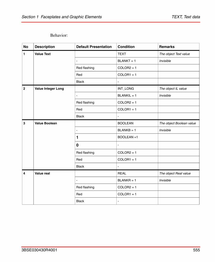
Section 1 Faceplates and Graphic Elements TEXT, Text data
Behavior:
No Description Default Presentation Condition Remarks
1 Value Text TEXT The object Text value
- BLANKT = 1 Invisible
Red flashing COLOR2 = 1
Red COLOR1 = 1
Black -
2 Value Integer Long INT_LONG The object IL value
- BLANKIL = 1 Invisible
Red flashing COLOR2 = 1
Red COLOR1 = 1
Black -
3 Value Boolean BOOLEAN The object Boolean value
- BLANKB = 1 Invisible
1 BOOLEAN =1
0 -
Red flashing COLOR2 = 1
Red COLOR1 = 1
Black -
4 Value real REAL The object Real value
- BLANKR = 1 Invisible
Red flashing COLOR2 = 1
Red COLOR1 = 1
Black -
3BSE030430R4001 555
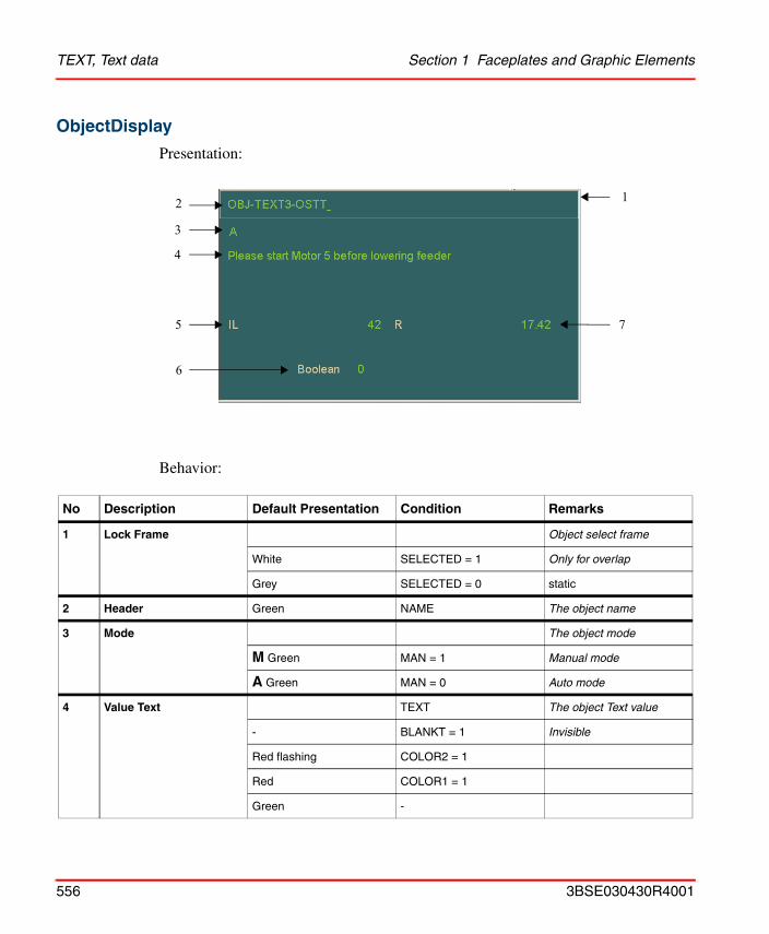
TEXT, Text data Section 1 Faceplates and Graphic Elements
ObjectDisplay
Presentation:
Behavior:
No Description Default Presentation Condition Remarks
1 Lock Frame Object select frame
White SELECTED = 1 Only for overlap
Grey SELECTED = 0 static
2 Header Green NAME The object name
3 Mode The object mode
M Green MAN = 1 Manual mode
A Green MAN = 0 Auto mode
4 Value Text TEXT The object Text value
- BLANKT = 1 Invisible
Red flashing COLOR2 = 1
Red COLOR1 = 1
Green -
2
3
4
5
6
7
1
556 3BSE030430R4001
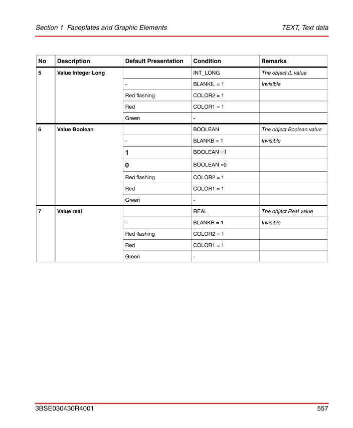
Section 1 Faceplates and Graphic Elements TEXT, Text data
5 Value Integer Long INT_LONG The object IL value
- BLANKIL = 1 Invisible
Red flashing COLOR2 = 1
Red COLOR1 = 1
Green -
6 Value Boolean BOOLEAN The object Boolean value
- BLANKB = 1 Invisible
1 BOOLEAN =1
0 BOOLEAN =0
Red flashing COLOR2 = 1
Red COLOR1 = 1
Green -
7 Value real REAL The object Real value
- BLANKR = 1 Invisible
Red flashing COLOR2 = 1
Red COLOR1 = 1
Green -
No Description Default Presentation Condition Remarks
3BSE030430R4001 557
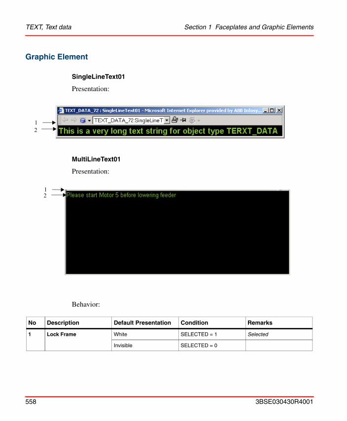
TEXT, Text data Section 1 Faceplates and Graphic Elements
Graphic Element
SingleLineText01
Presentation:
MultiLineText01
Presentation:
Behavior:
No Description Default Presentation Condition Remarks
1 Lock Frame White SELECTED = 1 Selected
Invisible SELECTED = 0
12
12
558 3BSE030430R4001
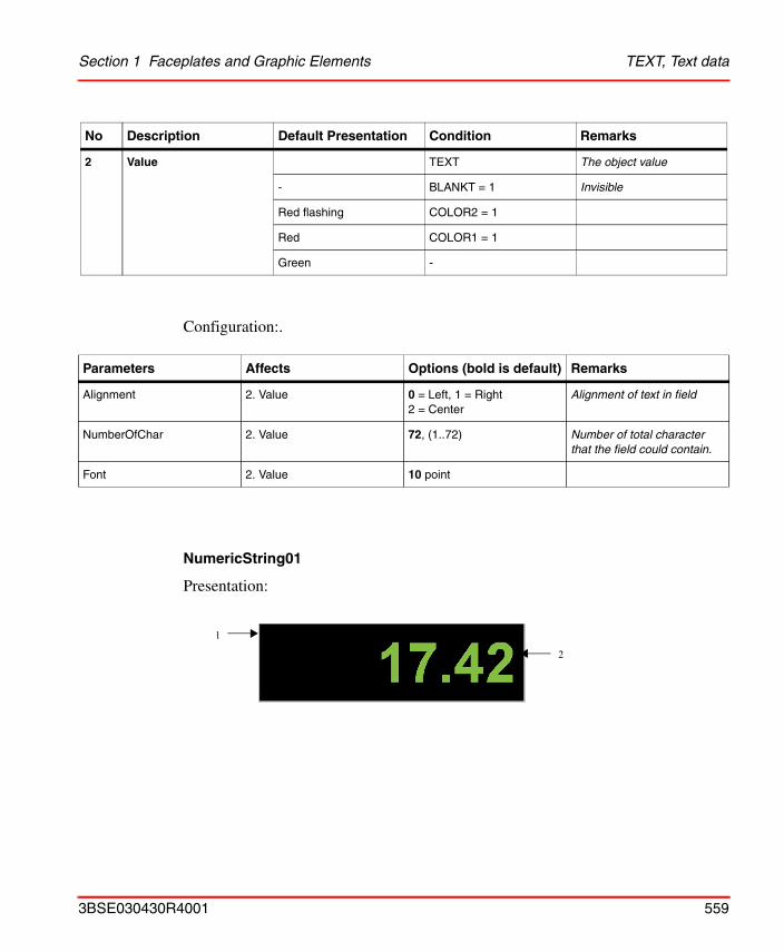
Section 1 Faceplates and Graphic Elements TEXT, Text data
Configuration:.
NumericString01
Presentation:
2 Value TEXT The object value
- BLANKT = 1 Invisible
Red flashing COLOR2 = 1
Red COLOR1 = 1
Green -
Parameters Affects Options (bold is default) Remarks
Alignment 2. Value 0 = Left, 1 = Right2 = Center
Alignment of text in field
NumberOfChar 2. Value 72, (1..72) Number of total character that the field could contain.
Font 2. Value 10 point
No Description Default Presentation Condition Remarks
1
2
3BSE030430R4001 559
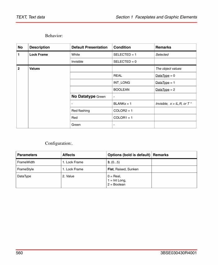
TEXT, Text data Section 1 Faceplates and Graphic Elements
Behavior:
Configuration:.
No Description Default Presentation Condition Remarks
1 Lock Frame White SELECTED = 1 Selected
Invisible SELECTED = 0
2 Values The object values
REAL DataType = 0
INT_LONG DataType = 1
BOOLEAN DataType = 2
No Datatype Green -
- BLANKx = 1 Invisible, x = IL,R, or T *
Red flashing COLOR2 = 1
Red COLOR1 = 1
Green -
Parameters Affects Options (bold is default) Remarks
FrameWidth 1. Lock Frame 3, (0...5)
FrameStyle 1. Lock Frame Flat, Raised, Sunken
DataType 2. Value 0 = Real,1 = Int Long,2 = Boolean
560 3BSE030430R4001
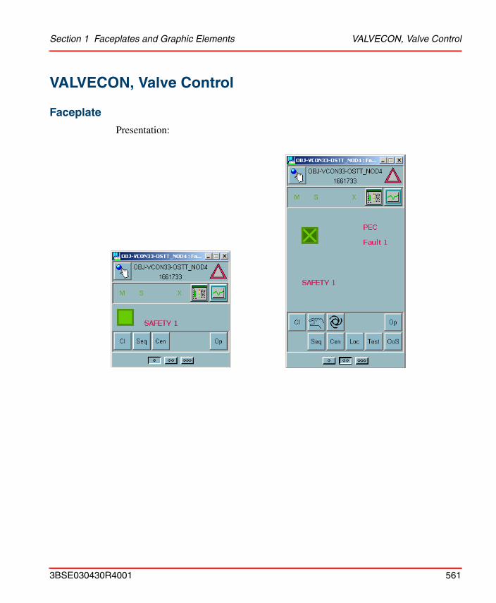
Section 1 Faceplates and Graphic Elements VALVECON, Valve Control
VALVECON, Valve Control
Faceplate
Presentation:
3BSE030430R4001 561
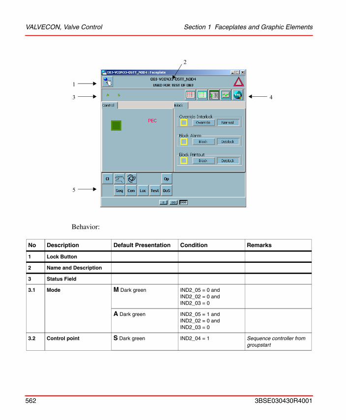
VALVECON, Valve Control Section 1 Faceplates and Graphic Elements
Behavior:
No Description Default Presentation Condition Remarks
1 Lock Button
2 Name and Description
3 Status Field
3.1 Mode M Dark green IND2_05 = 0 and IND2_02 = 0 and IND2_03 = 0
A Dark green IND2_05 = 1 and IND2_02 = 0 and IND2_03 = 0
3.2 Control point S Dark green IND2_04 = 1 Sequence controller from groupstart
1
3
5
4
2
562 3BSE030430R4001
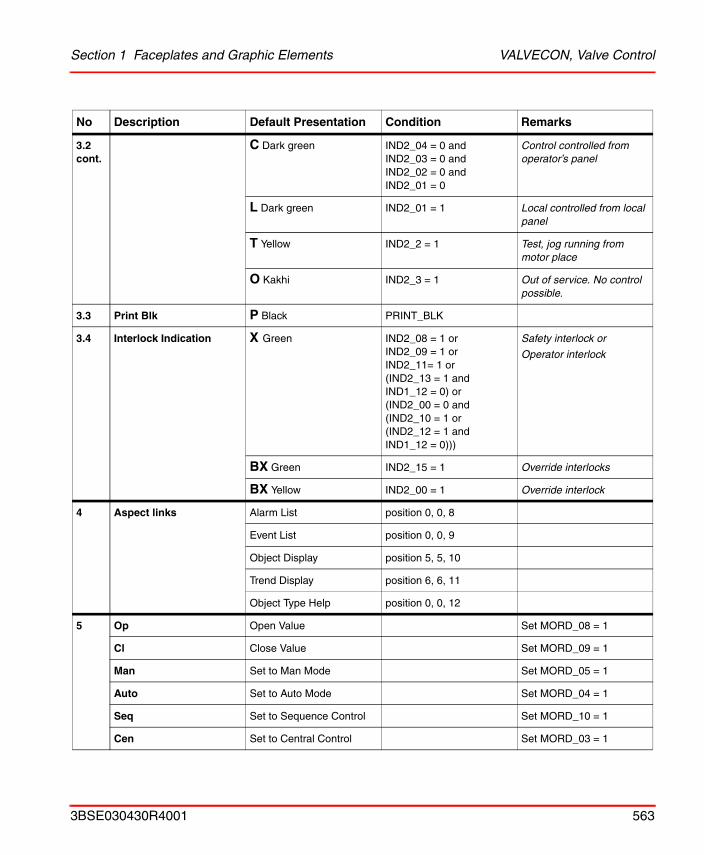
Section 1 Faceplates and Graphic Elements VALVECON, Valve Control
3.2 cont.
C Dark green IND2_04 = 0 and IND2_03 = 0 and IND2_02 = 0 and IND2_01 = 0
Control controlled from operator’s panel
L Dark green IND2_01 = 1 Local controlled from local panel
T Yellow IND2_2 = 1 Test, jog running from motor place
O Kakhi IND2_3 = 1 Out of service. No control possible.
3.3 Print Blk P Black PRINT_BLK
3.4 Interlock Indication X Green IND2_08 = 1 orIND2_09 = 1 orIND2_11= 1 or(IND2_13 = 1 andIND1_12 = 0) or(IND2_00 = 0 and(IND2_10 = 1 or(IND2_12 = 1 and IND1_12 = 0)))
Safety interlock or
Operator interlock
BX Green IND2_15 = 1 Override interlocks
BX Yellow IND2_00 = 1 Override interlock
4 Aspect links Alarm List position 0, 0, 8
Event List position 0, 0, 9
Object Display position 5, 5, 10
Trend Display position 6, 6, 11
Object Type Help position 0, 0, 12
5 Op Open Value Set MORD_08 = 1
Cl Close Value Set MORD_09 = 1
Man Set to Man Mode Set MORD_05 = 1
Auto Set to Auto Mode Set MORD_04 = 1
Seq Set to Sequence Control Set MORD_10 = 1
Cen Set to Central Control Set MORD_03 = 1
No Description Default Presentation Condition Remarks
3BSE030430R4001 563
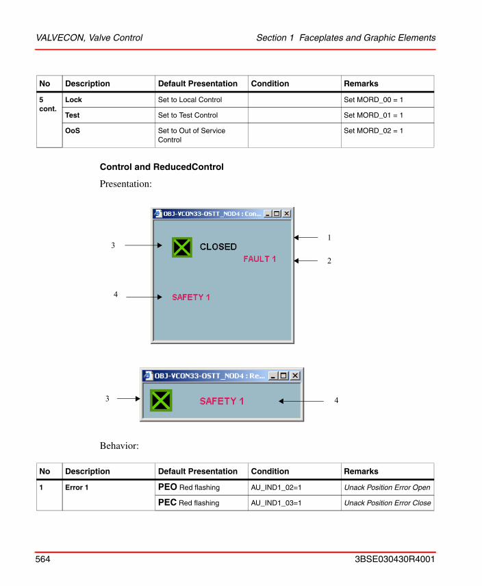
VALVECON, Valve Control Section 1 Faceplates and Graphic Elements
Control and ReducedControl
Presentation:
Behavior:
5 cont.
Lock Set to Local Control Set MORD_00 = 1
Test Set to Test Control Set MORD_01 = 1
OoS Set to Out of Service Control
Set MORD_02 = 1
No Description Default Presentation Condition Remarks
1 Error 1 PEO Red flashing AU_IND1_02=1 Unack Position Error Open
PEC Red flashing AU_IND1_03=1 Unack Position Error Close
No Description Default Presentation Condition Remarks
13
4
2
3 4
564 3BSE030430R4001
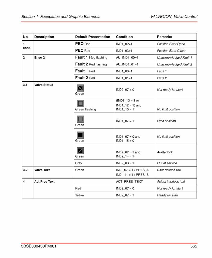
Section 1 Faceplates and Graphic Elements VALVECON, Valve Control
1 cont.
PEO Red IND1_02=1 Position Error Open
PEC Red IND1_03=1 Position Error Close
2 Error 2 Fault 1 Red flashing AU_IND1_00=1 Unacknowledged Fault 1
Fault 2 Red flashing AU_IND1_01=1 Unacknowledged Fault 2
Fault 1 Red IND1_00=1 Fault 1
Fault 2 Red IND1_01=1 Fault 2
3.1 Valve Status
GreenIND2_07 = 0 Not ready for start
Green flashing
(IND1_13 = 1 or
IND1_12 = 1) andIND1_15 = 1 No limit position
GreenIND1_07 = 1 Limit position
GreenIND1_07 = 0 andIND1_15 = 0
No limit position
GreenIND2_07 = 1 andIND2_14 = 1
A-Interlock
Grey IND2_03 = 1 Out of service
3.2 Valve Text Green INDI_07 = 1 / PRES_A
INDI_11 = 1 / PRES_B
User defined text
4 Act Pres Text ACT_PRES_TEXT Actual interlock text
Red IND2_07 = 0 Not ready for start
Yellow IND2_07 = 1 Ready for start
No Description Default Presentation Condition Remarks
3BSE030430R4001 565
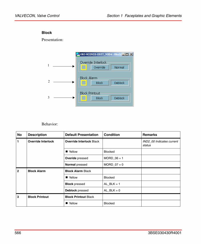
VALVECON, Valve Control Section 1 Faceplates and Graphic Elements
Block
Presentation:
Behavior:
No Description Default Presentation Condition Remarks
1 Override Interlock Override Interlock Black IND2_00 Indicates current status
! Yellow Blocked
Overide pressed MORD_06 = 1
Normal pressed MORD_07 = 0
2 Block Alarm Block Alarm Black
! Yellow Blocked
Block pressed AL_BLK = 1
Deblock pressed AL_BLK = 0
3 Block Printout Block Printout Black
! Yellow Blocked
1
2
3
566 3BSE030430R4001
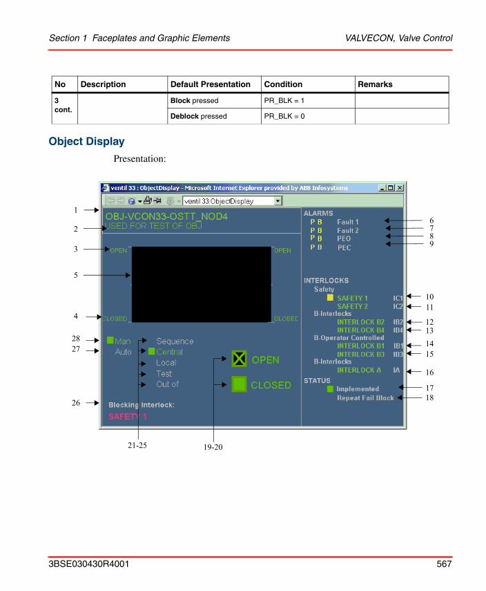
Section 1 Faceplates and Graphic Elements VALVECON, Valve Control
Object Display
Presentation:
3 cont.
Block pressed PR_BLK = 1
Deblock pressed PR_BLK = 0
No Description Default Presentation Condition Remarks
1
2
3
4
5
6789
1011
12131415
16
1718
19-2021-25
26
2728
3BSE030430R4001 567
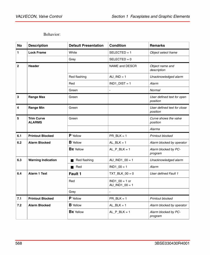
VALVECON, Valve Control Section 1 Faceplates and Graphic Elements
Behavior:
No Description Default Presentation Condition Remarks
1 Lock Frame White SELECTED = 1 Object select frame
Grey SELECTED = 0
2 Header NAME and DESCR Object name and description
Red flashing AU_IND = 1 Unacknowledged alarm
Red IND1_DIST = 1 Alarm
Green - Normal
3 Range Max Green User defined text for open position
4 Range Min Green User defined text for close position
5 Trim CurveALARMS
Green Curve shows the valve position
Alarms
6.1 Printout Blocked P Yellow PR_BLK = 1 Printout blocked
6.2 Alarm Blocked B Yellow AL_BLK = 1 Alarm blocked by operator
Bx Yellow AL_P_BLK = 1 Alarm blocked by PC-program
6.3 Warning Indication Red flashing AU_IND1_00 = 1 Unacknowledged alarm
Red IND1_00 = 1 Alarm
6.4 Alarm 1 Text Fault 1 TXT_BLK_00 = 0 User defined Fault 1
Red IND1_00 = 1 or AU_IND1_00 = 1
Grey -
7.1 Printout Blocked P Yellow PR_BLK = 1 Printout blocked
7.2 Alarm Blocked B Yellow AL_BLK = 1 Alarm blocked by operator
Bx Yellow AL_P_BLK = 1 Alarm blocked by PC-program
568 3BSE030430R4001
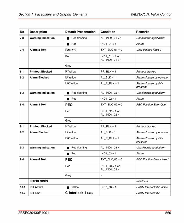
Section 1 Faceplates and Graphic Elements VALVECON, Valve Control
7.3 Warning Indication Red flashing AU_IND1_01 = 1 Unacknowledged alarm
Red IND1_01 = 1 Alarm
7.4 Alarm 2 Text Fault 2 TXT_BLK_01 = 0 User defined Fault 2
Red IND1_01 = 1 or AU_IND1_01 = 1
Grey -
8.1 Printout Blocked P Yellow PR_BLK = 1 Printout blocked
8.2 Alarm Blocked B Yellow AL_BLK = 1 Alarm blocked by operator
Bx Yellow AL_P_BLK = 1 Alarm blocked by PC-program
8.3 Warning Indication Red flashing AU_IND1_02 = 1 Unacknowledged alarm
Red IND1_02 = 1 Alarm
8.4 Alarm 3 Text PEO TXT_BLK_02 = 0 PEO Position Error Open
Red IND1_02 = 1 or AU_IND1_02 = 1
Grey -
9.1 Printout Blocked P Yellow PR_BLK = 1 Printout blocked
9.2 Alarm Blocked B Yellow AL_BLK = 1 Alarm blocked by operator
Bx Yellow AL_P_BLK = 1 Alarm blocked by PC-program
9.3 Warning Indication Red flashing AU_IND1_03 = 1 Unacknowledged alarm
Red IND1_03 = 1 Alarm
9.4 Alarm 4 Text PEC TXT_BLK_03 = 0 PEC Position Error closed
Red IND1_03 = 1 or AU_IND1_03 = 1
Grey -
INTERLOCKS Interlocks
10.1 IC1 Active Yellow IND2_08 = 1 Safety Interlock IC1 active
10.2 IC1 Text C-Interlock 1 Grey Safety Interlock IC1
No Description Default Presentation Condition Remarks
3BSE030430R4001 569
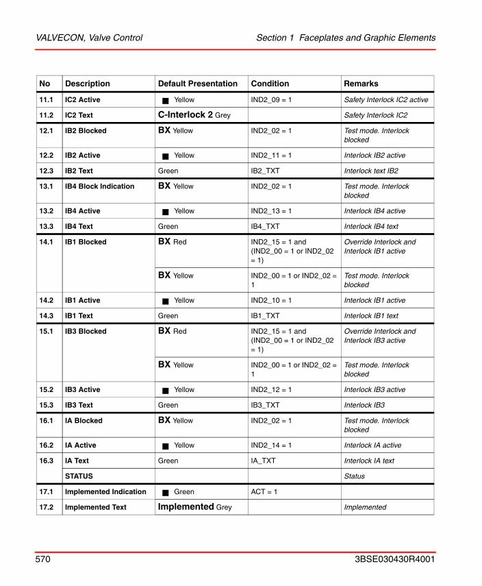
VALVECON, Valve Control Section 1 Faceplates and Graphic Elements
11.1 IC2 Active Yellow IND2_09 = 1 Safety Interlock IC2 active
11.2 IC2 Text C-Interlock 2 Grey Safety Interlock IC2
12.1 IB2 Blocked BX Yellow IND2_02 = 1 Test mode. Interlock blocked
12.2 IB2 Active Yellow IND2_11 = 1 Interlock IB2 active
12.3 IB2 Text Green IB2_TXT Interlock text IB2
13.1 IB4 Block Indication BX Yellow IND2_02 = 1 Test mode. Interlock blocked
13.2 IB4 Active Yellow IND2_13 = 1 Interlock IB4 active
13.3 IB4 Text Green IB4_TXT Interlock IB4 text
14.1 IB1 Blocked BX Red IND2_15 = 1 and(IND2_00 = 1 or IND2_02 = 1)
Override Interlock and Interlock IB1 active
BX Yellow IND2_00 = 1 or IND2_02 = 1
Test mode. Interlock blocked
14.2 IB1 Active Yellow IND2_10 = 1 Interlock IB1 active
14.3 IB1 Text Green IB1_TXT Interlock IB1 text
15.1 IB3 Blocked BX Red IND2_15 = 1 and(IND2_00 = 1 or IND2_02 = 1)
Override Interlock and Interlock IB3 active
BX Yellow IND2_00 = 1 or IND2_02 = 1
Test mode. Interlock blocked
15.2 IB3 Active Yellow IND2_12 = 1 Interlock IB3 active
15.3 IB3 Text Green IB3_TXT Interlock IB3
16.1 IA Blocked BX Yellow IND2_02 = 1 Test mode. Interlock blocked
16.2 IA Active Yellow IND2_14 = 1 Interlock IA active
16.3 IA Text Green IA_TXT Interlock IA text
STATUS Status
17.1 Implemented Indication Green ACT = 1
17.2 Implemented Text Implemented Grey Implemented
No Description Default Presentation Condition Remarks
570 3BSE030430R4001
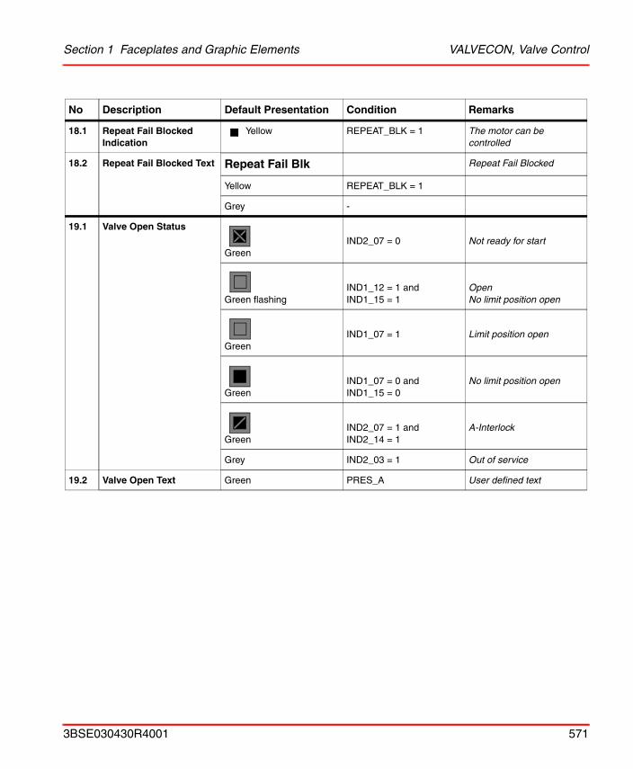
Section 1 Faceplates and Graphic Elements VALVECON, Valve Control
18.1 Repeat Fail Blocked Indication
Yellow REPEAT_BLK = 1 The motor can be controlled
18.2 Repeat Fail Blocked Text Repeat Fail Blk Repeat Fail Blocked
Yellow REPEAT_BLK = 1
Grey -
19.1 Valve Open Status
GreenIND2_07 = 0 Not ready for start
Green flashingIND1_12 = 1 andIND1_15 = 1
OpenNo limit position open
GreenIND1_07 = 1 Limit position open
GreenIND1_07 = 0 andIND1_15 = 0
No limit position open
GreenIND2_07 = 1 andIND2_14 = 1
A-Interlock
Grey IND2_03 = 1 Out of service
19.2 Valve Open Text Green PRES_A User defined text
No Description Default Presentation Condition Remarks
3BSE030430R4001 571
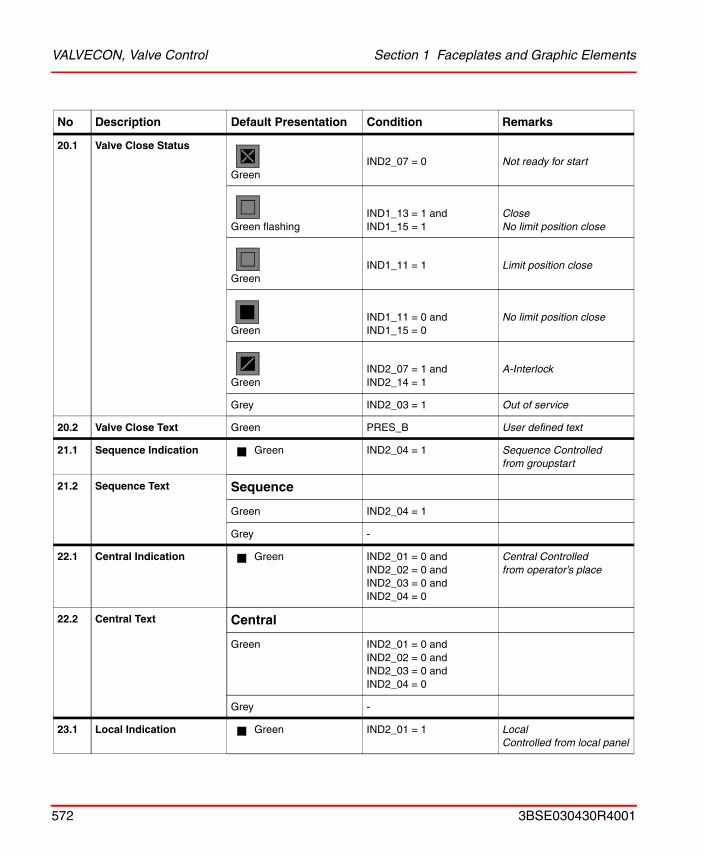
VALVECON, Valve Control Section 1 Faceplates and Graphic Elements
20.1 Valve Close Status
GreenIND2_07 = 0 Not ready for start
Green flashingIND1_13 = 1 andIND1_15 = 1
CloseNo limit position close
GreenIND1_11 = 1 Limit position close
GreenIND1_11 = 0 andIND1_15 = 0
No limit position close
GreenIND2_07 = 1 andIND2_14 = 1
A-Interlock
Grey IND2_03 = 1 Out of service
20.2 Valve Close Text Green PRES_B User defined text
21.1 Sequence Indication Green IND2_04 = 1 Sequence Controlled from groupstart
21.2 Sequence Text Sequence
Green IND2_04 = 1
Grey -
22.1 Central Indication Green IND2_01 = 0 andIND2_02 = 0 andIND2_03 = 0 andIND2_04 = 0
Central Controlled from operator’s place
22.2 Central Text Central
Green IND2_01 = 0 andIND2_02 = 0 andIND2_03 = 0 andIND2_04 = 0
Grey -
23.1 Local Indication Green IND2_01 = 1 Local Controlled from local panel
No Description Default Presentation Condition Remarks
572 3BSE030430R4001
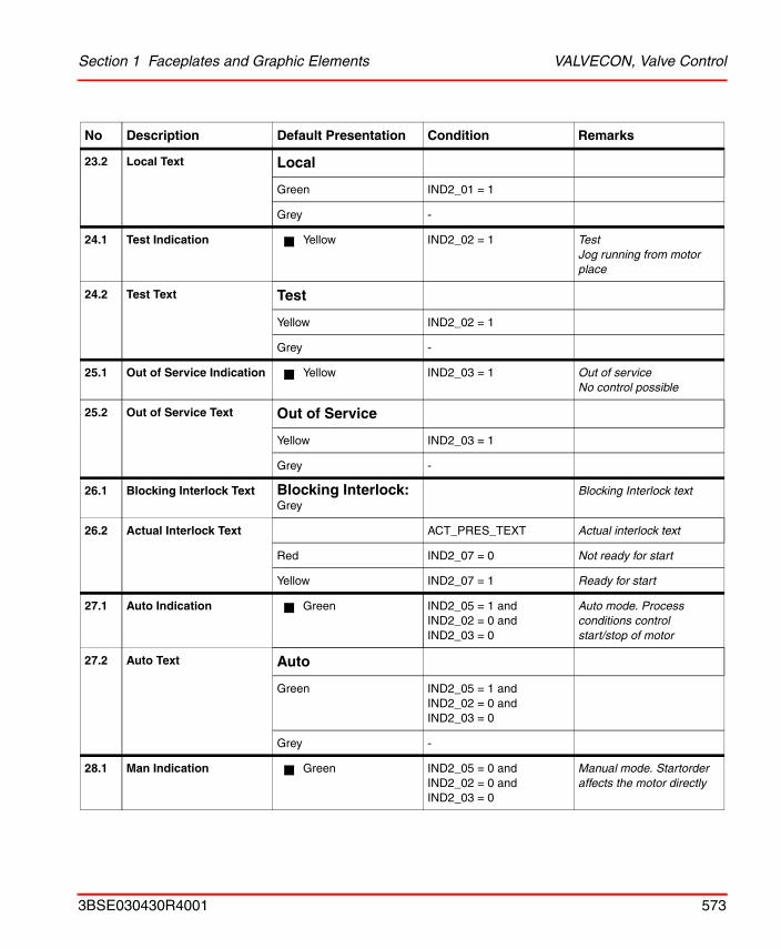
Section 1 Faceplates and Graphic Elements VALVECON, Valve Control
23.2 Local Text Local
Green IND2_01 = 1
Grey -
24.1 Test Indication Yellow IND2_02 = 1 TestJog running from motor place
24.2 Test Text Test
Yellow IND2_02 = 1
Grey -
25.1 Out of Service Indication Yellow IND2_03 = 1 Out of serviceNo control possible
25.2 Out of Service Text Out of Service
Yellow IND2_03 = 1
Grey -
26.1 Blocking Interlock Text Blocking Interlock: Grey
Blocking Interlock text
26.2 Actual Interlock Text ACT_PRES_TEXT Actual interlock text
Red IND2_07 = 0 Not ready for start
Yellow IND2_07 = 1 Ready for start
27.1 Auto Indication Green IND2_05 = 1 andIND2_02 = 0 andIND2_03 = 0
Auto mode. Process conditions control start/stop of motor
27.2 Auto Text Auto
Green IND2_05 = 1 andIND2_02 = 0 andIND2_03 = 0
Grey -
28.1 Man Indication Green IND2_05 = 0 andIND2_02 = 0 andIND2_03 = 0
Manual mode. Startorder affects the motor directly
No Description Default Presentation Condition Remarks
3BSE030430R4001 573
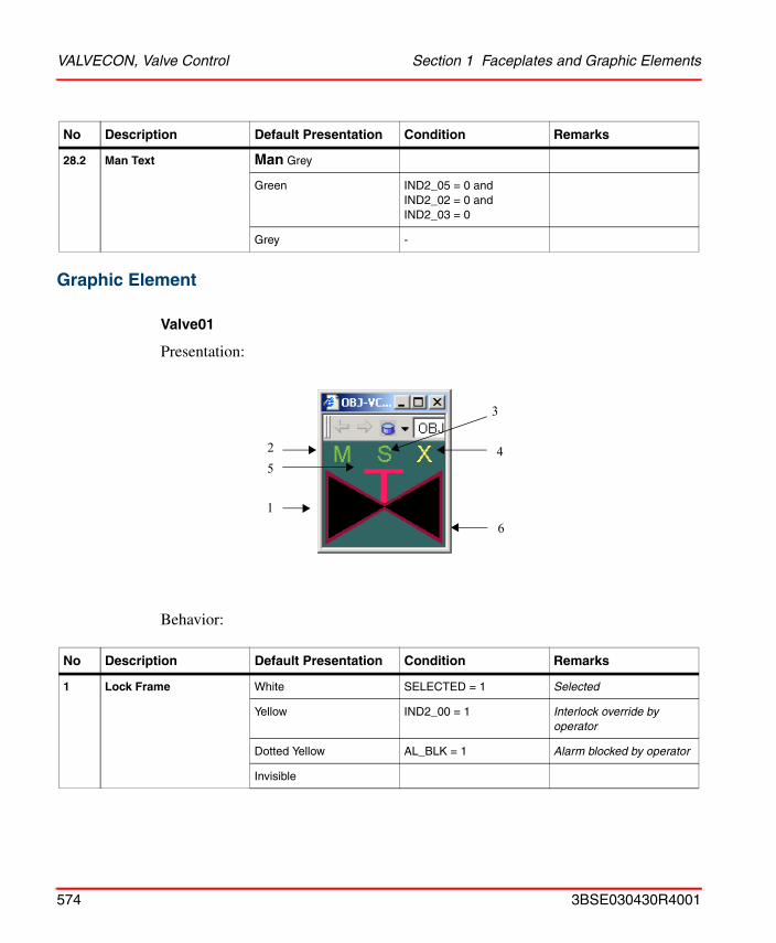
VALVECON, Valve Control Section 1 Faceplates and Graphic Elements
Graphic Element
Valve01
Presentation:
Behavior:
28.2 Man Text Man Grey
Green IND2_05 = 0 andIND2_02 = 0 andIND2_03 = 0
Grey -
No Description Default Presentation Condition Remarks
1 Lock Frame White SELECTED = 1 Selected
Yellow IND2_00 = 1 Interlock override by operator
Dotted Yellow AL_BLK = 1 Alarm blocked by operator
Invisible
No Description Default Presentation Condition Remarks
1
25
4
6
3
574 3BSE030430R4001
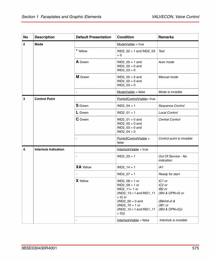
Section 1 Faceplates and Graphic Elements VALVECON, Valve Control
2 Mode ModeVisible = true
* Yellow IND2_02 = 1 and IND2_03 = 0
Test
A Green IND2_05 = 1 andIND2_02 = 0 andIND2_03 = 0
Auto mode
M Green IND2_05 = 0 andIND2_02 = 0 andIND2_03 = 0
Manual mode
- ModeVisible = false Mode is invisible
3 Control Point PointofControlVisible= true
S Green IND2_04 = 1 Sequence Control
L Green IND2_01 = 1 Local Control
C Green IND2_01 = 0 and IND2_02 = 0 and IND2_03 = 0 and IND2_04 = 0
Central Control
- PointofControlVisible = false
Control point is invisible
4. Interlock Indication InterlockVisible = true
- IND2_03 = 1 Out Of Service - No indication
XA Yellow IND2_14 = 1 IA1
- IND2_07 = 1 Ready for start
X Yellow IND2_08 = 1 orIND2_09 = 1 orIND2_11= 1 or(IND2_13 = 1 and IND1_11 = 0) or(IND2_00 = 0 and(IND2_10 = 1 or(IND2_12 = 1 and IND1_11 = 0)))
IC1 orIC2 orIB2 or(IB4 & OPN=0) or
(BlkIntl=0 &(IB1 or(IB3 & OPN=0)))
- InterlockVisible = false Interlock is invisible
No Description Default Presentation Condition Remarks
3BSE030430R4001 575
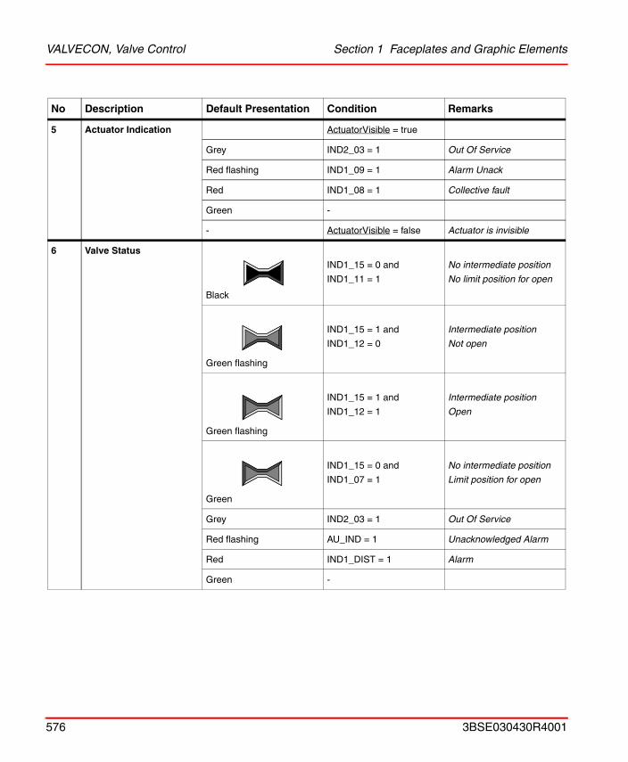
VALVECON, Valve Control Section 1 Faceplates and Graphic Elements
5 Actuator Indication ActuatorVisible = true
Grey IND2_03 = 1 Out Of Service
Red flashing IND1_09 = 1 Alarm Unack
Red IND1_08 = 1 Collective fault
Green -
- ActuatorVisible = false Actuator is invisible
6 Valve Status
Black
IND1_15 = 0 and
IND1_11 = 1
No intermediate position
No limit position for open
Green flashing
IND1_15 = 1 and
IND1_12 = 0
Intermediate position
Not open
Green flashing
IND1_15 = 1 and
IND1_12 = 1
Intermediate position
Open
Green
IND1_15 = 0 and
IND1_07 = 1
No intermediate position
Limit position for open
Grey IND2_03 = 1 Out Of Service
Red flashing AU_IND = 1 Unacknowledged Alarm
Red IND1_DIST = 1 Alarm
Green -
No Description Default Presentation Condition Remarks
576 3BSE030430R4001
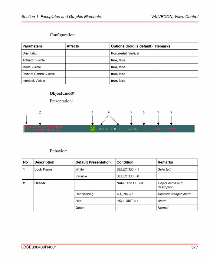
Section 1 Faceplates and Graphic Elements VALVECON, Valve Control
Configuration:
ObjectLine01
Presentation:
Behavior:
Parameters Affects Options (bold is default) Remarks
Orientation Horizontal, Vertical
Actuator Visible true, false
Mode Visible true, false
Point of Control Visible true, false
Interlock Visible true, false
No Description Default Presentation Condition Remarks
1 Lock Frame White SELECTED = 1 Selected
Invisible SELECTED = 0
2 Header NAME and DESCR Object name and description
Red flashing AU_IND = 1 Unacknowledged alarm
Red IND1_DIST = 1 Alarm
Green - Normal
1 2 3 4 5 6 7 8
3BSE030430R4001 577
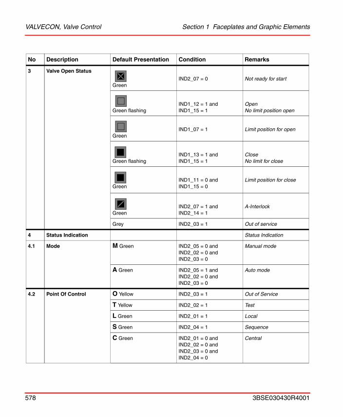
VALVECON, Valve Control Section 1 Faceplates and Graphic Elements
3 Valve Open Status
GreenIND2_07 = 0 Not ready for start
Green flashingIND1_12 = 1 andIND1_15 = 1
OpenNo limit position open
GreenIND1_07 = 1 Limit position for open
Green flashingIND1_13 = 1 andIND1_15 = 1
Close No limit for close
GreenIND1_11 = 0 andIND1_15 = 0
Limit position for close
GreenIND2_07 = 1 andIND2_14 = 1
A-Interlock
Grey IND2_03 = 1 Out of service
4 Status Indication Status Indication
4.1 Mode M Green IND2_05 = 0 andIND2_02 = 0 andIND2_03 = 0
Manual mode
A Green IND2_05 = 1 andIND2_02 = 0 andIND2_03 = 0
Auto mode
4.2 Point Of Control O Yellow IND2_03 = 1 Out of Service
T Yellow IND2_02 = 1 Test
L Green IND2_01 = 1 Local
S Green IND2_04 = 1 Sequence
C Green IND2_01 = 0 andIND2_02 = 0 andIND2_03 = 0 andIND2_04 = 0
Central
No Description Default Presentation Condition Remarks
578 3BSE030430R4001
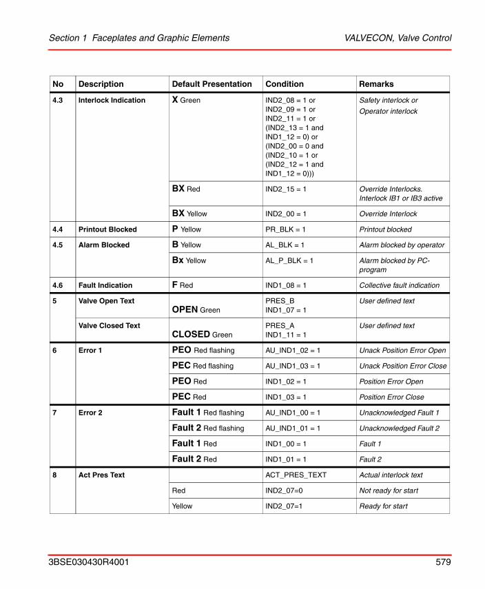
Section 1 Faceplates and Graphic Elements VALVECON, Valve Control
4.3 Interlock Indication X Green IND2_08 = 1 orIND2_09 = 1 orIND2_11 = 1 or(IND2_13 = 1 and IND1_12 = 0) or(IND2_00 = 0 and(IND2_10 = 1 or(IND2_12 = 1 and IND1_12 = 0)))
Safety interlock or
Operator interlock
BX Red IND2_15 = 1 Override Interlocks. Interlock IB1 or IB3 active
BX Yellow IND2_00 = 1 Override Interlock
4.4 Printout Blocked P Yellow PR_BLK = 1 Printout blocked
4.5 Alarm Blocked B Yellow AL_BLK = 1 Alarm blocked by operator
Bx Yellow AL_P_BLK = 1 Alarm blocked by PC-program
4.6 Fault Indication F Red IND1_08 = 1 Collective fault indication
5 Valve Open TextOPEN Green
PRES_BIND1_07 = 1
User defined text
Valve Closed TextCLOSED Green
PRES_AIND1_11 = 1
User defined text
6 Error 1 PEO Red flashing AU_IND1_02 = 1 Unack Position Error Open
PEC Red flashing AU_IND1_03 = 1 Unack Position Error Close
PEO Red IND1_02 = 1 Position Error Open
PEC Red IND1_03 = 1 Position Error Close
7 Error 2 Fault 1 Red flashing AU_IND1_00 = 1 Unacknowledged Fault 1
Fault 2 Red flashing AU_IND1_01 = 1 Unacknowledged Fault 2
Fault 1 Red IND1_00 = 1 Fault 1
Fault 2 Red IND1_01 = 1 Fault 2
8 Act Pres Text ACT_PRES_TEXT Actual interlock text
Red IND2_07=0 Not ready for start
Yellow IND2_07=1 Ready for start
No Description Default Presentation Condition Remarks
3BSE030430R4001 579
VALVECON, Valve Control Section 1 Faceplates and Graphic Elements
580 3BSE030430R4001

3BSE030430R4001. Printed in Sweden October 2004Copyright © 2003–2004 by ABB. All Rights Reserved® Registered Trademark of ABB.™ Trademark of ABB.
Automation Technology ProductsMannheim, Germanywww.abb.de/processautomationemail: [email protected]
Automation Technology Products Västerås, Swedenwww.abb.com/processautomationemail: [email protected]
Automation Technology ProductsWickliffe, Ohio, USAwww.abb.com/processautomationemail: [email protected]
http://www.abb.com/control