indoor positioning technologies
TRANSCRIPT

Research Collection
Habilitation Thesis
Indoor positioning technologies
Author(s): Mautz, Rainer
Publication Date: 2012
Permanent Link: https://doi.org/10.3929/ethz-a-007313554
Rights / License: In Copyright - Non-Commercial Use Permitted
This page was generated automatically upon download from the ETH Zurich Research Collection. For moreinformation please consult the Terms of use.
ETH Library
Indoor Positioning Technologies
Habilitation Thesis
submitted to ETH Zurich
Application for Venia Legendi in Positioning and Engineering Geodesy
Dr. Rainer Mautz
Institute of Geodesy and Photogrammetry, Department of Civil, Environmental and Geomatic
Engineering, ETH Zurich
February 2012

1

2
Acknowledgements
First,IwouldliketoacknowledgethepromotionofthisthesisbythereferentProf.Dr.HilmarIngensand, InstituteofGeodesyandPhotogrammetry,ETHZurich.Particularlyvaluable tomehavebeenopen‐mindeddiscussionswithhimandhisnetworkedthinkingwhichinspiredmetoproducesuchacomprehensivework.
I am indebted to the co‐referent Prof. Dr. AlainGeiger, aswell as tomy colleagues SebastianTilchandDavidGrimmwhotooktheirtimetoproof‐readthispublicationandtoprovidefruitfulsuggestions.
LastbutnotleastIwouldsincerelythankMarkLeylandforcorrectingtheEnglishtext.Hishelpnotonlyimprovedthequalityofthisthesis,butenrichedmyEnglishlanguageingeneral.
My wife Guang was so patient with my late nights, and I want to thank her for her faithfulsupportinwritingthiswork.

3
Contents Acknowledgements.........................................................................................................................................2
Abstract...............................................................................................................................................................6
1 Introduction.............................................................................................................................................7
1.1 Motivation..........................................................................................................................................................7
1.2 PreviousSurveys.............................................................................................................................................8
1.3 OverviewofTechnologies...........................................................................................................................9
1.4 IndoorPositioningApplications............................................................................................................11
1.5 StructureofthisWork...............................................................................................................................14
2 UserRequirements.............................................................................................................................15
2.1 RequirementsParametersOverview..................................................................................................15
2.2 PositioningRequirementsParametersDefinition.........................................................................17
2.3 ManMachineInterfaceRequirements................................................................................................19
2.4 SecurityandPrivacyRequirements.....................................................................................................20
2.5 Costs..................................................................................................................................................................20
2.6 GenericDerivationofUserRequirements.........................................................................................20
2.7 RequirementsforSelectedIndoorApplications.............................................................................21
3 DefinitionofTerms.............................................................................................................................25
3.1 DisambiguationofTermsforPositioning..........................................................................................25
3.2 DefinitionofTechnicalTerms................................................................................................................27
3.3 TheBasicMeasuringPrinciples.............................................................................................................29
3.4 PositioningMethods...................................................................................................................................31
4 Cameras..................................................................................................................................................34
4.1 Referencefrom3DBuildingModels....................................................................................................35
4.2 ReferencefromImages..............................................................................................................................36
4.3 ReferencefromDeployedCodedTargets..........................................................................................37
4.4 ReferencefromProjectedTargets........................................................................................................38
4.5 SystemswithoutReference.....................................................................................................................39
4.6 ReferencefromOtherSensors...............................................................................................................40
4.7 SummaryonCameraBasedIndoorPositioningSystems...........................................................40
5 Infrared...................................................................................................................................................42
5.1 ActiveBeacons..............................................................................................................................................42
5.2 ImagingofNaturalInfraredRadiation...............................................................................................43
5.3 ImagingofArtificialInfraredLight.......................................................................................................43
5.4 SummaryonInfraredIndoorPositioningSystems.......................................................................44

4
6 TactileandCombinedPolarSystems...........................................................................................45
6.1 TactileSystems.............................................................................................................................................45
6.2 CombinedPolarSystems..........................................................................................................................46
6.3 SummaryonTactileandCombinedPolarSystems.......................................................................49
7 Sound.......................................................................................................................................................50
7.1 Ultrasound......................................................................................................................................................50
7.2 AudibleSound...............................................................................................................................................55
7.3 SummaryonSoundSystems...................................................................................................................56
8 WLAN/Wi‐Fi.........................................................................................................................................57
8.1 PropagationModeling................................................................................................................................57
8.2 CellofOrigin..................................................................................................................................................58
8.3 EmpiricalFingerprinting..........................................................................................................................58
8.4 WLANDistanceBasedMethods(Pathloss‐BasedPositioning)................................................60
8.5 SummaryonWLANSystems...................................................................................................................64
9 RadioFrequencyIdentification......................................................................................................65
9.1 ActiveRFID.....................................................................................................................................................66
9.2 PassiveRFID..................................................................................................................................................66
9.3 SummaryonRFIDSystems......................................................................................................................67
10 Ultra‐Wideband................................................................................................................................69
10.1 RangeEstimationUsingUWB.................................................................................................................70
10.2 MultipathMitigationUsingUWB..........................................................................................................71
10.3 PositioningMethodsUsingUWB...........................................................................................................71
10.4 CommercialUWBSystems.......................................................................................................................74
10.5 SummaryonUltra‐WidebandSystems...............................................................................................74
11 HighSensitiveGNSS/AssistedGNSS........................................................................................75
11.1 SignalAttenuation.......................................................................................................................................75
11.2 AssistedGNSS................................................................................................................................................76
11.3 LongIntegrationandParallelCorrelation.........................................................................................77
11.4 SummaryonHighSensitiveGNSS........................................................................................................78
12 Pseudolites.........................................................................................................................................79
12.1 PseudolitesUsingSignalsDifferenttoGNSS....................................................................................80
12.2 GNSSRepeaters............................................................................................................................................80
12.3 SummaryonPseudoliteSystems..........................................................................................................82
13 OtherRadioFrequencyTechnologies......................................................................................83
13.1 ZigBee...............................................................................................................................................................83
13.2 Bluetooth.........................................................................................................................................................84

5
13.3 DECTPhones.................................................................................................................................................84
13.4 DigitalTelevision.........................................................................................................................................85
13.5 CellularNetworks........................................................................................................................................85
13.6 Radar.................................................................................................................................................................87
13.7 FMRadio..........................................................................................................................................................90
13.8 SummaryonRadioSystems....................................................................................................................90
14 InertialNavigationSystems.........................................................................................................92
14.1 INSNavigationwithoutExternalInfrastructure............................................................................92
14.2 PedestrianDeadReckoning.....................................................................................................................93
14.3 INSPedestrianNavigationUsingComplementarySensors.......................................................94
14.4 FootMountedPedestrianNavigation..................................................................................................97
14.5 SummaryonINSBasedSystems...........................................................................................................99
15 MagneticLocalization...................................................................................................................100
15.1 SystemsUsingtheAntennaNearField............................................................................................100
15.2 SystemsUsingMagneticFieldsfromCurrents.............................................................................100
15.3 SystemsUsingPermanentMagnets..................................................................................................102
15.4 SystemsUsingMagneticFingerprinting.........................................................................................103
15.5 SummaryonMagneticLocalization..................................................................................................103
16 InfrastructureSystems................................................................................................................104
16.1 PowerLines.................................................................................................................................................104
16.2 FloorTiles....................................................................................................................................................104
16.3 FluorescentLamps...................................................................................................................................105
16.4 LeakyFeederCables................................................................................................................................105
16.5 SummaryonInfrastructureSystems................................................................................................106
17 ConcludingRemarks.....................................................................................................................107
17.1 Conclusion...................................................................................................................................................107
17.2 Outlook..........................................................................................................................................................107
Acronyms.......................................................................................................................................................108
Symbols...........................................................................................................................................................111
References.....................................................................................................................................................112

6
Abstract
Intheageofautomationtheabilitytonavigatepersonsanddevicesinindoorenvironmentshasbecomeincreasinglyimportantforarisingnumberofapplications.Withtheemergenceofglobalsatellitepositioningsystems,theperformanceofoutdoorpositioninghasbecomeexcellent,butmanymassmarket applications require seamless positioning capabilities in all environments.Thereforeindoorpositioninghasbecomeafocusofresearchanddevelopmentduringthepastdecade.
Ithasbynowbecomeapparent that there isnooverallsolutionbasedonasingle technology,such as that provided outdoors by satellite‐based navigation. We are still far away fromachieving cheap provision of global indoor positioning with an accuracy of 1 meter. Currentsystems require dedicated local infrastructure and customized mobile units. As a result, therequirements for every application must be analyzed separately to provide an individuallytailored solution. Therefore it is important to assess the performance parameters of alltechnologiescapableof indoorpositioningandmatch themwith theuser requirementswhichhavetobedescribedpreciselyforeachapplication.Suchdescriptionsmustbebasedonamarketanalysiswhere therequirementsparametersneed tobecarefullyweighedagainsteachother.The number of relevant requirements parameters is large (e.g. accuracy, coverage, integrity,availability, update rate, latency, costs, infrastructure, privacy, approval, robustness,intrusivenessetc.).Butalsothediversityofdifferenttechnologiesislarge,makingitacomplexprocesstomatchasuitabletechnologywithanapplication.Atthehighestlevel,alltechnologiescanbedividedintocategoriesemployingthreedifferentphysicalprinciples:inertialnavigation(accelerometers and gyroscopes maintaining angular momentum), mechanical waves (i.e.audibleandultra‐sound)andelectromagneticwaves(i.e.usingthevisible,infrared,microwaveand radio spectrum). Systems making use of the radio spectrum include FM radios, radars,cellularnetworks,DECTphones,WLAN,ZigBee,RFID,ultra‐wideband,highsensitiveGNSSandpseudolitesystems.
This thesis categorizes all sighted indoorpositioning approaches into13distinct technologiesanddescribesthemeasuringprinciplesofeach.Individualapproachesarecharacterizedandkeyperformance parameters are quantified. For a better overview, these parameters are brieflycomparedintableformforeachtechnology.

1.1 Motivation 7
1 Introduction
Subsequenttothe2010and2011InternationalConferencesonIndoorPositioningandIndoorNavigation(IPIN),theauthorwasrepeatedlyaskedtoprovidekeynotepresentationstogiveanoverviewofcurrentindoorpositioningtechnologies.Anobviouslackofavailableinformationonthistopicinspiredtheideatocreatethissurveyofexistingtechniquesforindoorpositioningandnavigation. An attempt is being made to comprehensively describe relevant approaches,developments and products, at the expense of omitting technical details. Cited referencesprovide suchdetails for each specific systemapproach. To guide the reader in the process ofselectinganappropriatetechnology,thesystemparametersandtypicalperformancelevelsarecomparedtoeachother.
Systems based on micro‐ and nanomeasuring technologies for applications with measuringranges below 1m have not been included in this survey. The reason is that developments ofsmall‐scale technologies are mainly driven by the manufacturers’ research departments andthereforeremainunpublishedsolutions.
AnextensivelistofapplicationareasisgiveninSection1.4.Itrevealsthesignificanceofindoorpositioning to our society and explains the necessity for further research efforts to put theseapplicationsintopractice.
1.1 Motivation
Following the achievements of satellite‐based location services in outdoor applications thechallengehasshiftedtotheprovisionofsuchservicesfortheindoorenvironment.However,theabilitytolocateobjectsandpeopleindoorsremainsasubstantialchallenge,formingthemajorbottleneck preventing seamless positioning in all environments. Many indoor positioningapplications are waiting for a satisfactory technical solution. Improvements in indoorpositioning performance have the potential to create unprecedented opportunities forbusinesses.
Thequestionwhy thisworkdraws adistinctionbetween indoor andoutdoorpositioninghasbeenraised. In fact,mostpositioningsystemscan–at least theoretically–beused indoorsaswellasoutdoors.Howeversystemperformancesdiffergreatly,becausetheenvironmentshaveanumber of substantial dissimilarities. Indoor environments are particularly challenging forpositioning,i.e.positionfinding,forseveralreasons:
severemultipathfromsignalreflectionfromwallsandfurniture Non‐Line‐of‐Sight(NLoS)conditions
1 Introduction 8
highattenuationandsignalscatteringduetogreaterdensityofobstacles fasttemporalchangesduetothepresenceofpeopleandopeningofdoors highdemandforprecisionandaccuracy
Ontheotherhand,indoorsettingsfacilitatepositioningandnavigationinmanyways:
smallcoverageareas lowweatherinfluencessuchassmalltemperaturegradientsandslowaircirculation fixedgeometricconstraintsfromplanarsurfacesandorthogonalityofwalls infrastructuresuchaselectricity,internetaccess,wallssuitablefortargetmounting lowerdynamicsduetoslowerwalkinganddrivingspeeds.
Anotherreasonwhyindoorpositioninghasincreasinglybecomeafocusofresearchisthatthedominating technologies for positioning in outdoor environments, namely GNSS (GlobalNavigationSatelliteSystems),performpoorlywithinbuildings.TheindoorenvironmentlacksasystemthatpossessestheexcellentperformanceparametersofoutdoorGNSSintermsofglobalcoverage,highaccuracy,short latency,highavailability,high integrityand lowuser‐costs.Likeindoorsettings,certainoutdoorenvironmentsarenotwellcoveredbyGNSSduetoinsufficientviews to the open sky. Therefore, positioning systems targeting ‘GNSS challenged’ outdoorenvironmentshavebeenincludedinthisstudy.Preciselyspeaking,thissurveyaimstodescribeall positioning techniques relevant to challenging environments – even including GNSSapproachessuitableforsuchenvironments.Forsimplicityhowever,thetermindoorpositioningiskeptthroughoutthisreport.
1.2 Previous Surveys
Hightower andBorriello (2001) set up a classification scheme in order to help developers oflocation‐aware applications tobetter evaluate their optionswhen choosing a location‐sensingsystem.Atthisearlystageinthedevelopmentofindoorpositioningsystems,15systemswerecomparedintermsofaccuracy,precision,scale,costsandlimitations.Thequantificationsgiven10yearsagoarehardlyvalid today.The rapidprogress in thisemerging field requiresanewsurveyevery3to5yearsinordertorepresentausefulstate‐of‐the‐artguide.
An extensive survey ofwireless indoorpositioning techniques and solutionshasbeen carriedoutbyLiuetal.(2007).Theirsurveydetailsthestate‐of‐the‐artin2005ofGPS,RFID,Cellular‐Based,UWB,WLANandBluetoothtechnologies.Theperformanceparametersof20systemsandsolutionsarecomparedintermsofaccuracy,precision,complexity,scalabilityandrobustness.
The textbook of Bensky (2007) describes radio‐navigation techniques comprehensively andprovidesdetailsonmethodsfordistanceestimationbetweenradios.
Asurveyof themathematicalmethodsused for indoorpositioningcanbe found inSecoet al.(2009).Thestudyfocusesonwirelesspositioningtechniquesgroupedintothefourcategories:geometry‐basedmethods,cost‐functionminimization,fingerprintingandBayesiantechniques.
Mautz(2009)evaluated13different indoorpositioningsolutionswith focusonhighprecisiontechnologiesoperatinginthemmtocmlevel.Theevaluationiscarriedoutfromtheperspectiveof a geodesist and includes the criteria accuracy, range, signal frequency, principle, marketmaturityandacquisitioncosts.

1.3 Overview of Technologies 9
Thesesurveysdemonstrateconceptualheterogenity,differencesinmarketmaturity,varietyintheapplicationaddressedanddissimilaritiesindesign.Thereforeitisdifficult–ifnotimpossible–toaccomplishobjectiveperformancebenchmarking.
1.3 Overview of Technologies
Allsystemapproachesdescribedinthisworkhavebeendividedinto13differenttechnologies.Accordingly,eachchapterisdedicatedtoadistinctiveindoorpositioningtechnology.Evenifthetechnologyemployedisofminorimportancetotheuser,thechoiceforthiscategorizationisthatsystemsusingthesametechnologycanbeeasilycomparedintheirperformanceparameters.
Table1.1characterizesthesensortechnologiesathigh‐level.Thevaluesspecifiedforaccuracyandcoveragearegiven in formof intervalswhereinmost approaches reside.Therearemanyexceptions exceeding these intervals. Similarly, only the main measuring principles andapplications arementioned in the table.More details can be found in the tables found in theindividualchapters.
Table1.1Overviewofindoorpositioningtechnologies.Coveragereferstorangesofsinglenodes.
Chapter / Technology Typical
Accuracy
Typical
Coverage (m)
Typical
Measuring Principle
Typical
Application
Page
4 Cameras 0.1mm – dm 1 – 10 angle measurements from images metrology, robot navigation 34
5 Infrared cm – m 1 – 5 thermal imaging, active beacons people detection, tracking 42
6 Tactile & Polar Systems μm – mm 3 – 2000 mechanical, interferometry automotive, metrology 45
7 Sound cm 2 – 10 distances from time of arrival hospitals, tracking 50
8 WLAN / WiFi m 20 – 50 fingerprinting pedestrian navigation, LBS 57
9 RFID dm – m 1 – 50 proximity detection, fingerprinting pedestrian navigation 65
10 Ultra‐Wideband cm – m 1 – 50 body reflection, time of arrival robotics, automation 69
11 High Sensitive GNSS 10 m ‘global’ parallel correlation, assistant GPS location based services 75
12 Pseudolites cm – dm 10 – 1000 carrier phase ranging GNSS challenged pit mines 79
13 Other Radio Frequencies m 10 – 1000 fingerprinting, proximity person tracking 83
14 Inertial Navigation 1 % 10 – 100 dead reckoning pedestrian navigation 92
15 Magnetic Systems mm – cm 1 – 20 fingerprinting and ranging hospitals, mines 100
16 Infrastructure Systems cm – m building fingerprinting, capacitance ambient assisted living 104
A graphical overview in dependence of accuracy and coverage is given in Figure 1.1. Thecoverageistoberegardedasthedirectmeasuringrangeofanunextendedimplementation,i.e.thespatialscalabilitywhichmanysystemapproachesofferhasnotbeentakenintoaccount(e.g.deployment of additional sensor nodes). If a system architecture includes a combination ofdifferent sensor technologies (e.g. inertial navigation andWLAN), then thework is describedunderthechapterwiththetechnologythatismostsignificanttothesystemapproach.
Most technologies rely onelectromagneticwavesanda fewonmechanical (sound)waves.Ascanbeseen fromFigure1.2a largepartof theelectromagneticspectrumcanbeexploited forindoorpositioning.Highaccuracysystemstendtoemployshorterwavelengths.

1 Introduction 10
Figure1.1Overviewofindoortechnologiesindependenceonaccuracyandcoverage
Figure1.2Indoortechnologiesindependenceonaccuracyandcarrierwavelength

1.4 Indoor Positioning Applications 11
1.4 Indoor Positioning Applications
The list of applications below demonstrates the omnipresent need for indoor positioningcapability in ourmodern way of life. Moreover, along with an improvement of performance,futuregenerationsofindoorpositioningsystemswillfindevenmoreapplicationswhichareatthepresenttimenotfeasible.
1.4.1 Location Based Services in Indoor Environments
Commerciallyhighlyrelevantapplicationsforthemassmarketaretheso‐calledLocation‐BasedServices (LBS) which make use of the geographical position to deliver context‐dependentinformationaccessiblewithamobiledevice.Suchservicesarerequired indoorsandoutdoors.Examples of indoor LBS are obtaining safety information or topical information on cinemas,concertsoreventsinthevicinity.LBSapplicationsincludenavigationtotherightstoreinamallorofficeinapublicbuilding.Withinastoreorwarehouse,thelocationdetectionofproductsisof interest to the owner as well as to the customers. In particular, location‐basedadvertisements,location‐basedbillingandlocalsearchserviceshaveahighcommercialvalue.Atlarge tradeshows, there is a request to guide the visitors to the correct exposition booths.Applications at train or bus stations include the navigation to the right platform or bus stop.Further examples of LBS are proximity‐based notification, profile matching and theimplementationofautomatedlogon/logoffproceduresincompanies.Thereisalsoaddedvalueforthepositioningprovider,e.g.byresourcetracking,fleetmanagementanduserstatistics.
1.4.2 Private Homes
Applicationsathomes includethedetectionof lost items,physicalgesturegamesand locationbasedservicesathome.AmbientAssistantLiving(AAL)systemsprovideassistanceforelderlypeople in their homeswithin their activities of daily living. A key function of AAL systems islocationawarenesswhichrequiresanindoorpositioningfunctionality.Applicationsathomearemedicalmonitoringsuchasmonitoringvitalsigns,detectionofemergenciesandfalldetection,butalsoserviceandpersonalizedentertainmentsystems,suchassmartaudiosystems(Zetiketal.2010).
1.4.3 Context Detection and Situational Awareness
Mobile devices provide a large variety of useful functions where it is desirable to have anautomatedadaptationof themobiledevicedependingona changeof theuser’s context. Suchfunctionalitysparestheuseradditionaleffortbyprovidingassistanceinindividualsituations.Toenablesuchanautomaticadaptation themobileuser’scontextneeds tobedeterminedby themobiledeviceitself.Themostsignificantcriteriatodeterminetheuser’scontextisthecurrentgeographicallocation.Forexampleasmartconferenceguidecanprovideinformationaboutthetopicdiscussedinnearbyauditoriums.
1.4.4 Medical Care
In hospitals the location tracking of medical personnel in emergency situations has becomeincreasingly important. Medical applications in hospital also include patient and equipmenttracking, e.g. fall detection of patients. Precise positioning is required for robotic assistanceduring surgeries. Existing analytical devices can be replaced with more efficient surgicalequipment.

1 Introduction 12
1.4.5 Social Networking
As a member of the young generation participation in the network has become increasinglyimportant because social integration is governed through the social network. Ubiquitouslocationplaysacentralroleinsocialnetworking,suchaslocatingfriendsforcoordinatingjointactivities.
1.4.6 Environmental Monitoring
Environmental monitoring is used to observe some phenomenon such as heat, pressure,humidity,airpollutionanddeformationofobjectsandstructures.Tomonitortheseparametersover a certain indoor or outdoor space, multiple sensor nodes are organized as a WirelessSensorNetwork(WSN).AWSNconsistsofsmall,inexpensive,spatiallydistributedautonomousnodeswithlimitedprocessingandcomputingresourcesandradiosforwirelesscommunication.A comprehensive literature review on WSNs can be found in Yick et al. (2008). In order toretrieve the nodes’ positions from ranging and proximity information among these sensornodes, dedicated algorithmsof cooperative localizationhavebeendeveloped, seeMautz et al.(2007a).
1.4.7 Police and Firefighters
Indoorpositioningcapabilitiesprovideimportantbenefitsinlawenforcement,rescueservices,andfireservicesi.e.locationdetectionoffiremeninabuildingonfire.Thepolicebenefitsfromseveralrelevantapplications,suchas instantaneousdetectionoftheftorburglary,detectionofthelocationofpolicedogstrainedtofindexplosivesinabuilding,locatingandrecoveryofstolenproductsforpost‐incidentinvestigations,crimescenerecovery,statisticsandtrainingbutalsointhepreventionofcrime,e.g.withtaggeddevicesforestablishingso‐calledgeofenceingi.e.alarmsystemswhichcandetectwhetherapersonoranassethasleftacertainareaunauthorized.
1.4.8 Intelligent Transportation
A mass user application for vehicles will be the provision of seamless navigation throughextensionofroadguidanceinsideparkinggarages(Wagneretal.2010).Inparticular,itbecomespossible to navigate the driver to a single parking spot and from there to the pedestriandestination(Gusenbaueretal.2010).
1.4.9 Industry
Mechanical engineering is developing towards intelligent systems for more or less fullyautomaticmanufacturing.Fornumerousindustrialapplicationsindoorpositionawarenessisanessentialfunctionalelement,suchasforroboticguidance,industrialrobots,robotcooperation,smart factories (e.g. toolassistancesystemsatcarassembly lines),automatedmonitoringandquality control. Indoor positioning capabilities can help to find taggedmaintenance tools andequipment scattered all over a plant in industrial production facilities. The improvement ofautomaticsafetysystems,intelligentworkerprotectionandcollisionavoidanceisdrivenbythepositioningcapabilityofsuchasystem.
1.4.10 Museums
Thereareseveralapplicationsinmuseums,suchasvisitortrackingforsurveillanceandstudyofvisitorbehavior,locationbaseduserguidingandtriggeredcontextawareinformationservices.
1.4.11 Financial Institutions For the seamless documentation of valuables during their transport, an indoor trackingcomponentisrequired.

1.4 Indoor Positioning Applications 13
1.4.12 Logistics and Optimization
Forthepurposeofprocessoptimizationincomplexsystems,itisessentialtohaveinformationaboutthelocationofassetsandstaffmembers.Inacomplexstorageenvironmentforexample,itis importantthatrequestedgoodsare foundquickly.Basedonaccurate localization, tracingofeverysingleunitbecomespossible.Positioningforcargomanagementsystemsatairports,portsandforrailtrafficaffordsunprecedentedopportunitiesforincreasingtheirefficiency.
1.4.13 Guiding of the Vulnerable People Systems designed specifically to aid the visually impaired should operate seamlessly in allindoor and outdoor environments. Navigation is generally required for vulnerable people toassistwalkingincombinationwithpublictransport.
1.4.14 Structural Health Monitoring
Sensors incorporated into steel reinforcements within concrete can perform strainmeasurementswithhighresolution.Strainsensingsystemsbasedonpassivesensor‐integratedRFIDs canmeasure strain changes anddeformation causedby loading anddeterioration (OKI2011).
1.4.15 Surveying and Geodesy Surveyingofthebuildinginteriorincludessettingoutandgeometrycaptureofnewbuildingsaswell as for reconstructions. Positioning capabilitieswith global reference are needed for datainputtoCAD,GISorCityGML.Accuracyrequirementsvaryfromcentimeterstomillimeters.
1.4.16 Construction Sites Apartfromsurveyingapplications,largeconstructionssitesrequirepositioningcapabilitiesthatcansupportaninformationmanagementsystem.Thecapabilitytolocalizeandtrackworkersisacrucialcomponenttoestablishanautomaticsafetysystem.
1.4.17 Underground Construction Specialpositioning requirements apply industy, dark,humidand space limitedenvironmentsfortunneling(Schneider2010)andlongwallmining(Finketal.2010).
1.4.18 Scene Modeling and Mapping
Scenemodeling–thetaskofbuildingdigital3Dmodelsofnaturalscenes–requiresthepreciseorientationoftheopticalsensor.Indoormappingsystemsneedtoknowthecamera’spositioninorder tomergemultipleviewsandgenerate3Dpoint clouds. Scenemodeling isbeneficial forseveral applicationssuchascomputeranimation,notablyvirtual training,geometricmodelingforphysicalsimulation,mappingofhazardoussitesandculturalheritagepreservation.
1.4.19 Motion Capturing
Motion capturing relies on the detection of physical gestures and the capability to locate andtrackbodyparts.Suchtechnologiesareusefulformedicalstudiesandanimatedfilms.Locationbased gaming, such as exergaming (gaming as a form of exercise) relies on tracking bodymovementorreactionoftheplayers.
1.4.20 Applications Based on Augmented Reality
LocalizationawarenessisoffundamentalimportanceforAugmentedReality(AR)applications–an increasinglypowerful tool to superimposegraphicsor soundson theusers’ view,allowing

1 Introduction 14
the user to perceive overlaid information which is spatially and semantically related to theenvironment.AnexampleofvisionbasednavigationforARispresentedinKimandJun(2008).
1.4.21 Further Applications Applicationsareaswhichhavenotbeenexplicitlymentionedaboveare self‐organizing sensornetworks, ubiquitous computing, computer vision, industrial metrology, architecture,archeology,civilengineering,pipeinspection(i.e.locatingpipes)andfacilitymanagement.
1.5 Structure of this Work
This introduction is followed by an overview of the user requirement parameters for indoorpositioningapplications inChapter2.Thekeyrequirementsaredefined,agenericmethod forderivation of requirements is shown and the requirements of some selected applications arequantified.Chapter3definestechnicaltermsfrequentlyusedinthefieldof indoorpositioning.The basicmeasuring principles and positioningmethods are briefly described. Chapters4–16aredevotedtoamoredetailedpresentationofdifferenttechnologies.Eachchapter introducesanindividualtechnologyandcharacterizessomerepresentativesystemimplementations.Attheendofeachchapterashortconclusionsummarizesthefindingsandprovidesanoverviewofthekeyparametersintableform.Chapter17closesthethesiswithsomegeneralconclusionsdrawnfrom the presented literature, along with a suggestion on how the current insufficiency insystemperformancescanbesystematicallyimproved.

2.1 Requirements Parameters Overview 15
2 User Requirements
Acrucialelementforanyinitiativetodesignanindoorpositioningsystemisathoroughstudyoftheuserrequirementsandspecificapplicationdescriptionsinordertojustifytheresearchanddevelopment in this field. Requirements for significant applications should drive the futuredirectionofresearch.Thereforeit is importanttostatewell‐groundedfiguresofrequirementsparametersandallocatesuitabletechnologies.
In this chapter anoverviewof the user requirementparameters is given in Section2.1 and amorecomprehensivedefinitionofthekeyrequirementscanbefoundinSection2.2.Inaddition,agenericmethodtodeterminethevaluesforaspecificapplicationisindicated.Thechapterisconcluded in Section2.7 by summarizing results of different studies on indoor positioningrequirements.
2.1 Requirements Parameters Overview
Thefollowinglistofdifferentparameterscanbeusedasabasisforassessmentandcomparisonof different indoor positioning systems. Due to the large number of criteria, it is notstraightforwardforausertoidentifytheoptimalsystemforaparticularapplication.Figure2.1illustratesthecomplexityandmulti‐dimensionalityoftheoptimizationproblemconfrontingtheuser.Foreachapplication,the16userrequirementsneedtobeweightedagainsteachother.Thedifferentrequirementsarelistedbelowwithsomeexamplevaluesgiveninbrackets.Apartfromtheseuserrequirements,thereareotherimportanttechnicalparametersof indoorpositioningsystemssuchasthoseshowninFigure2.2.
Figure2.1Userrequirements Figure2.2 Importanttechnicalparametersbeing

2 User Requirements 16
lesssignificanttotheuserInordertoservemarketneedstheembeddedtechnologyshouldbeadequately low‐cost, low‐power, low‐latency,miniaturized, require lowmaintenance andminimal amount of dedicatedinfrastructure.Researchoftenneglectsissuessuchassecurity,privacyandreliability.
2.1.1 List of the most Important User Requirements
accuracy/measurementuncertainty(mm,cm,dm,meter,decameterlevel) coveragearea/limitationstocertainenvironments(singleroom,building,city,global) cost(uniquesystemset‐upcosts,peruserdevicecosts,perroomcosts,maintenancecosts), required infrastructure (none, markers, passive tags, active beacons, pre‐existing or
dedicated,localorglobal), marketmaturity(concept,development,product) output data (2D‐, 3D coordinates, relative, absolute or symbolic position, dynamic
parameterssuchasspeed,heading,uncertainty,variances) privacy(activeorpassivedevices,mobileorserverbasedcomputation) updaterate(on‐event,onrequestorperiodicallye.g.100Hzoronceaweek) interface (man‐machine interfaces such as text based, graphical display, audio voice and
electricalinterfacessuchasRS‐232,USB,fiberchannelsorwirelesscommunications) systemintegrity(operabilityaccordingtechnicalspecification,alarmincaseofmalfunction) robustness(physicaldamage,theft,jamming,unauthorizedaccess) availability(likelihoodandmaximumdurationofoutages) scalability (not scalable, scalable with area‐proportional node deployment, scalable with
accuracyloss), numberofusers(singleusere.g.totalstation,unlimiteduserse.g.passivemobilesensors), intrusiveness/useracceptance(disturbing,imperceptible) approval(legalsystemoperation,certificationofauthorities)
2.1.2 Technical Parameters Less Important to the User
levelofhybridization(singlemodality,twodifferentsensors,highlyhybridsensorfusion). technology(optical,inertial,magnetic,sound,…) measuredquantity(direction,distance,signalamplitude,acceleration,time) basic measuring principle (tri‐)lateration, (tri‐)angulation, fingerprinting, cell of origin,
dead‐reckoning) positioningalgorithmused(multidimensionalscaling,multilateration,heuristics) signalused(soundwaves,electromagneticwaves,magneticfieldstrength) signalwavelength(visiblelight,infrared,radiofrequencies) systemarchitecture(centralordistributedsystems) application(navigation,surveying,industrytracking,metrology) coordinatereference(local,global,objectorsensorcoordinatesystem)
2.1.3 Evaluation of Positioning Systems
Inorderto findasuitablepositioningtechnologyforaparticularapplication, theperformanceparametersneedtobematchedwiththeuserrequirements.Theseparameters(listedaboveanddetailed inSection2.2)poseamultidimensionaloptimizationproblemwhensearchingforthebest match. Moreover, the values for the performance parameters are usually not exactlydeterminablesincetheyinturndependonvariousfactors,circumstancesandconditions.Eachsystem approach has not only its individual set of performance parameters, but also severalunique characteristics, conditions, assumptions and applications which need to be weighted
2.2 Positioning Requirements Parameters Definition 17
againsteachother.Weightingofallparametersandadditionalconditionscannotbedoneinanobjectivemanner.Therefore,fair‐mindedrankingofthesystemsisneitherusefulnorfeasible.
2.2 Positioning Requirements Parameters Definition
2.2.1 Accuracy / Measurement Uncertainty
Theaccuracyofasystemisan importantuserrequirementwhichshouldbequantified inanydescription of an application. The term accuracy has been defined in the Joint Committee forGuidesinMetrology(JCGM)astheclosenessofagreementbetweenameasuredquantityvalueand a true quantity value of a measurand. In the new concept of measurement uncertaintypublished in JCGM 200:2008 (2008) the term ‘true value’ has been discarded. In accordance,‘measurementaccuracy’isnotusedanymoreforquantificationofanumericalquantity.Insteadof‘measurementaccuracy’theterm‘measurementuncertainty’isusednowforquantificationofa standard deviation (including the two categories TypeA and TypeB). Measurementuncertaintycomprises,ingeneral,manycomponents.Onlysomeofthesecomponents(TypeA)may be evaluated from the statistical distribution. Components evaluated from probabilitydensity functionsbasedonexperienceorother informationbelongtoTypeB. Inorder to takeintoaccountallcomponentsofuncertainty,includingthosearisingfromsystematiceffects,suchascomponentsassociatedwithcorrections,allsystematicmeasurementerrorsmustbemodeledandcalibrationmustbecompletedbymeansofameasuredquantityvaluehavinganegligiblemeasurement uncertainty. However, researchers, developers and vendors still quantify theperformanceofindoorpositioningsystemsintermsof‘positioningaccuracy’.Inordertobeableto compare the system performances, the conventional definition of ‘positioning accuracy’ asreported in the sources is used throughout this book. ‘Positioning accuracy’ should beunderstoodasthedegreeofconformanceofanestimatedormeasuredpositionatagiventime,tothetruevalue,expressedfortheverticalandhorizontalcomponentsatthe95%confidencelevel. Ifnormaldistributioncanbeassumed,ausefulmetric for thequalityofpositions is thecomputationofthestandarddeviation(i.e.RMSD,RootMeanSquareDeviation)
1, (2.1)
wherenisthenumberofestimated(i.e.measured)positionvectors iandPithepositionvectorpredictedby amodel of the localizednode i, or, if only one single location is estimated,Pi isreplacedwith a single position vectorP0. A criterionwhich is less sensitive to outliers is theaverageabsolutepositiondeviation
1. (2.2)
InmostcasesapredictedlocationPiinEquations(2.1)and(2.2)isrepresentedbyanempiricalmean value. If the unknown coordinates are to be estimated from a redundant set ofobservations,theaverageoftheestimatedmeansquarepositionalvariances
1, (2.3)
canbecomputed,whereqxxi,qyyi,qzziarediagonalelementsofthevariance‐covariancematrixCxof the estimatedparameters as a result of a network adjustment. In this book, ‘low accuracy’

2 User Requirements 18
referstoastandarddeviationσP>10mand‘highaccuracy’toσP<1cmifnovalueofaccuracyisstatedexplicitly.
Althoughtheaccuracyofanindoorpositioningsystemisthekeydriverformostapplications,itneedstobeviewedincontextwiththeotherperformanceparametersdescribedbelow.
2.2.2 Coverage
Describesthespatialextensionwheresystemperformancemustbeguaranteedbyapositioningsystem.Oneofthefollowingcategoriesshouldbespecified:
a) LocalCoverage:asmallwell‐defined,limitedareawhichisnotextendable(e.g.asingleroomorbuilding).Forthiscase,thecoveragesizeisspecified(e.g.(m),(m2)or(m3)).
b) Scalable Coverage: Systemswith the ability to increase the area by adding hardware (e.g.throughdeploymentofadditionalsensors). In thisbook, theparameter ‘coverage’ isset to‘scalable’onlyifthescalabilityisnotaffectedbyalossofaccuracy.
c) GlobalCoverage:systemperformanceworldwideorwithinthedesired/specifiedarea.OnlyGNSSsystemsandcelestialnavigationbelongtothiscategory.
2.2.3 Integrity
Integrityrelatestotheconfidencewhichcanbeplacedintheoutputofasystem.Integrityriskistheprobabilitythatamalfunctioninthesystemleadstoanestimatedpositionthatdiffersfromtherequiredpositionbymorethananacceptableamount(thealarmlimit)andthattheuserisnot informed within the specified period of time (time‐to‐alarm). Regulatory bodies havestudied and defined integrity performance parameters in some sectors such as civil aviation,however,inothersectors,includingthoserelatingtoindoornavigationitismoredifficulttofindquantified integrityparameters.Fromtheapplicationdescription, thisrequirementparametershouldgivean indicationwhetherthedevices for integrityparametersarerelatedtoSafetyofLife(SoL),economicfactors,orconveniencefactors.Inacademicresearchpaperswhichdescribeindoorpositioningapproaches, the integrityparameter isusuallynot specified.Therefore thissurveydoesnottakeintegrityintoaccount.
2.2.4 Availability
Availability is thepercentageof timeduringwhich thepositioning service is available forusewith the required accuracy and integrity. This may be limited by random factors (failures,communications congestion) aswell asby scheduled factors (routinemaintenance).Generallyoneofthefollowingthreelevelscouldbespecified,althoughthiswilldependontheparticularapplication:
a) lowavailability: <95%b) regularavailability: >99%c) highavailability: >99.9%
To achieve availability, it is assumed that continuity, accuracy and integrity requirements arefulfilled. Application descriptions usually include specification of availability, whereas systemdevelopersusuallydonotspecifyanavailabilityfigure.
2.2.5 Continuity
Thecontinuityisthepropertyofcontinuousoperationofthesystemoveraconnectedperiodoftimetoperformaspecificfunction.Thefrequenciesofacceptableoutagesshouldbegiven.Thecontinuityrequirementisusuallysimilartothatofavailability.

2.3 Man Machine Interface Requirements 19
2.2.6 Update Rate
Theupdaterateisthefrequencywithwhichthepositionsarecalculatedonthedeviceoratanexternalprocessingfacility.Thefollowingtypesofmeasurementsratesexist:
a) periodic:regularupdate,specifiedinaninterval(unite.g.(Hz))b) onrequest:triggeredbytheuserorbyaremotedevice.c) onevent:measurementupdateinitiatedbythelocaldevicewhenaspecificeventoccurs,e.g.
whenatemperaturesensorexceedsacriticalthreshold.
2.2.7 System Latency
Thesystemlatencydescribesthedelaywithwhichtherequestedinformationisavailabletotheuser.Thelatencycanhavethefollowingvalues:
real time: Does not tolerate ‘perceivable’ delays. It is the most demanding latencyrequirement.Itisnecessaryfornavigationandalmostallindoorpositioningapplications.
soonerthebetter:Requiresthesystem’sbesteffort. soonerthebetterwithanUpperLimit:Requiresthesystem’sbesteffortbutthesystemmust
bedesignedtolimitthemaximumdelaytoaspecifiedthreshold. postprocessing:Nospecifictimeofdeliveryisdefined.
2.2.8 Data Output
In addition to times and positions, a number of spatio‐temporal data derivatives may berequired,many of these can be providedwithout significantly increasing the data capture orstoragerequirements.Thefollowingderivedvaluesareofinterestinmanyapplications:
speed/velocity acceleration heading/bearing predictedposition
The requirements specification should explicitlymention if the heading of a mobile object isneeded.Someapplicationsrequirethefullspatialorientation,e.g.informofvaluesfor6DegreesofFreedom(6DoF,i.e.3coordinateand3rotationparameters).
2.3 Man Machine Interface Requirements
Themanmachine interface requirements describe howposition informationwill be reportedandqueriedattheuserdevice.Thefollowingquestionsneedtobeansweredforanapplicationdescription.
2.3.1 Information Display – Spatial Data Requirements
Isagraphicaldisplayrequired? Isascaledmaprequiredoristopologicalcorrectnesssufficient? Isadditionalcartographic/mappedinformationrequired? Whatlevelofdetailisrequiredapproximately?
2.3.2 Data Query and Analysis Tools
Ison‐requeststatusinformationaboutthenetworkordevicesneeded? Isrouteplanninginformationrequired?

2 User Requirements 20
Isen‐routeguidance(visualoraudio)needed? AreNaturalLanguageInstructions(NLI)required?NLIisaconvenientwaytoprovideroute
informationtousers,offeringrichandflexiblemeansofdescribingnavigationalpaths.
2.4 Security and Privacy Requirements
Thefiguresaboutsecurityissuesshouldbegiven.Inaddition,severalaspectsofprivacy,suchasapprovalbytheuserneedtobeconsidered.
2.4.1 Requirements for Security and Safety
Thesecurityofasystemistheextentofprotectionagainstsomeunwantedoccurrencesuchastheinvasionofprivacy,theft,andthecorruptionofinformationorphysicaldamage.Thequalityorstateofbeingprotectedfromunauthorizedaccessoruncontrolledlossesoreffectsshouldbegiven.Safety isapropertyofadeviceorprocesswhich limitstheriskofaccidentbelowsomespecifiedacceptablelevel.
2.4.2 Requirements for Privacy and Approval
Thelevelofprivacyinfluencestheapprovalbytheuser:Howcomfortableareuserswiththeirdata(e.g.trajectory)beingstored?Dousershavelegalconcernsabouttheirprivacy?Ifso,canprivateusersbemotivatedtoprovidepersonaldata?
Approvalalsoincludestherequirementsforthesystemtoallowcertificationbyauthorities.E.g.ifthereisaneedforadmissibilityincourt,therequirementsforthesystemtodeliverevidenceshouldbegiven.Insurancecompaniesshouldpointouttheirpoliciesconcerningapproval.
2.5 Costs
The maximum cost of a positioning system is an important user requirement which can beassessed in severalways.Timecosts include factorssuchas the timerequired for installationand administration. Capital costs include factors such as the price permobile unit or systeminfrastructure and the salaries of support personnel. Maintenance costs include expensesrequired to keep the system functional. Space costs involve the amount of installedinfrastructureand thehardware’ssize.Thequantificationof thecostsshouldbehandledwithcareduetotime‐,location‐,manufacturer‐relateddependencies.
2.6 Generic Derivation of User Requirements
Figure 2.3 shows the general approach to define user requirements. First, the potential usergroups are defined and listed. Based on the user groups, their associated services aredetermined. Then theminimumhigh‐level functions that a potential positioning systemmustfulfill are defined. From these high level functions, a list of parameters to capture the userrequirements is derived. The data acquisition (step 5) is carried out from a combination ofsources.Primarilyausersurveyisperformedwithquestionnaires,brainstormingsessionsandinterviewsof industrypartners.Theevaluationof thequestionnaires, interviewsandsessionswith the user groups is then carried out for each user group and application separately. Theresultofsuchastudyisthesummaryoftheuserrequirementsparametersinanexplicitform.

2.7 Requirements for Selected Indoor Applications 21
Figure2.3Procedureforuserrequirementscapture
2.7 Requirements for Selected Indoor Applications
This section provides numerical targets of some application areas for indoor positioning asstated in various studies of experts. These numbers demonstrate large dissimilarity of userrequirements between different applications. Figure 2.4 shows an overview of requiredaccuraciesandrangesallowingfordirectcomparisonwiththeperformancesoftechnologiesinFigure1.1onpage10.
Figure2.4Overviewofuserrequirementsintermsofaccuracyandcoverage
1. Definition of potential user groups
3. Definition of high level functions
4. Definition of required parameters
5. Data acquisition
6. Detailed description of user requirements
7. Summary of user requirements in table form
2. Definition of potential services

2 User Requirements 22
2.7.1 Requirements for the Mass Market
Massmarket applications for indoor positioning require the use of standard deviceswithoutsupplementary physical components, e.g. major modifications to mobile phones in order toinclude a positioning function are out‐of‐scope in the mass market. The general userrequirementsformass‐marketlocalizationhavebeenputintonumbersbyWirolaetal.(2010),seeTable2.1.
Table2.1Summaryofrequirementsformass‐markedlocalizationaccordingtoWirolaetal.(2010)
Criteria Criteria Description Value
horizontal accuracy 2D position for the detection of a shelf in a supermarket 1 m
vertical accuracy selection of the correct floor and visualization floor detection
update rate minimum for navigation 1 Hz
latency delay with which position is available to the user none
TTFF Time‐To‐First‐Fix, latency after switching on the device without delay
privacy maintenance of the user privacy according to user‐set policy
2.7.2 Requirements for Underground Construction
Schneider (2010) details the positioning requirements for underground construction. Incontrast to pedestrian navigation applications, the positioning requirements for undergroundsurveying are more demanding in terms of accuracy which needs to be in the order ofmillimeters instead of meters. Other requirements such as constraints on costs, size andelectricalpowerarethereforelessdemanding.Additionalrequirementsapplyintermsofsystemrobustness.Table2.2quantifiestherequirementsasstatedbySchneider.
Table2.2SummaryofpositioningrequirementsinundergroundconstructionaccordingtoSchneider(2010)
Criteria Criteria Description Value
accuracy for deformation analysis 1 mm – 5 mm
accuracy for heading and machine guidance 1 cm – 5 cm
range depends on the application 20 m – 50 m
3D‐positioning tasks require 3D‐coordinates yes
resistance against perturbation, robustness
required against external impacts such as dust (especially close to tunnel face), emissions from construction machines, damage caused by ongoing construction (e.g. drill & blast), vibrations and tunnel deformations
yes
real‐time availability construction surveying tasks need results in real‐time 80%
user friendliness system should be operable by foremen without surveying background yes
costs system cost must not exceed that of a surveying totalstation 10’000 € ‐50’000 €
operability under non‐line of sight
system must be operable under NLoS conditions, continuous and direct LoS between the reference sensors and the work site is not always given
required
power supply availability for external electrical power guaranteed
2.7.3 Requirements for Indoor Surveying
Carpenters, architects, interior designers and fitters would benefit from a tool capable ofdelivering3Dpositionswithinmm‐accuracy.Suchatoolmustbeuser‐friendlyinthesensethatthe system set‐up is quick andwireless operation of a handheld device is possible. Real‐timetracking with 20Hz or more is necessary to allow for capturing profiles and maintainingrobustness during fast pivoting movements of the operator. An overview of the userrequirementsisgiveninTable2.3.

2.7 Requirements for Selected Indoor Applications 23
Table2.3Summaryofrequirementsinindoorsurveyingapplications
Criteria Criteria Description Value
accuracy 3D position compared to reference 2 mm (at 20 m)
coverage 3D measurement volume 20 m
size size of mobile measurement unit handheld
update rate high rates needed for tracking and fast movements 20 Hz
operating time time of battery life 10 hours
installation complexity time to set‐up system < 2 min
quality indicator self‐reporting of current accuracy yes
costs user price per unit < 3000 €
2.7.4 Requirements for Ambient Assisted Living
Prior to an evaluation of positioning systems for Ambient Assisted Living (AAL) throughcompetitive benchmarking (EvAAL2011) the user requirements for AAL applications weredefined inanopendiscussion. Itrevealeda2Daccuracyof0.5mto1mandanupdaterateof0.5s.Animportantrequirementisthe‘useracceptance’,whichdescribeshowintrusiveasystemis to theuser, e.g. does anelderlypersonnotice the systembywearing tagson thebody?AnoverviewoftherequirementsincludingtheirrelativeweightsisgiveninTable2.4.
Table2.4SummaryofrequirementsinAALapplications
Criteria Criteria Description Value Weight
accuracy 2D position compared to reference 0.5 m – 1 m 0.25
installation complexity man‐minutes to install an AAL system in a flat < 1 hour 0.20
user acceptance qualitative measure describing invasiveness non‐invasive 0.20
availability fraction of time a system is active and responsive > 90 % 0.15
integrability of AAL use of standards and open protocols ‐ 0.10
update rate Sample interval of the location system 0.5 s ‐
coverage area of a typical flat 90 m2 ‐
costs not assessed within the evaluation ‐ ‐
2.7.5 Requirements for First Responders
Rantakokko et al. (2010) quantify the requirements for enforcement officers, firefighters andmilitarypersonnel.TheyidentifythefollowingkeyrequirementsasstatedinTable2.5.
Table2.5SummaryofrequirementsforfirstrespondersaccordingtoRantakokkoetal.(2010)
Criteria Criteria Description Value
horizontal accuracy need for specific room determination ≤ 1 m
vertical accuracy need for determination of a specific floor in a building ≤ 2 m
update rate updates need to provide constant accessibility permanent
latency delay with which position is available to the user none
weight weight of personal localization and tracking gear < 1 kg
cost price of complete positioning system < €1000
Further requirements include physical robustness, encrypted communication, estimation ofuncertainty, compatibility with other information sources, real‐time map‐building, and userfriendliness.
2.7.6 Requirements for Law Enforcement
ThestudyofMautz(2005)describesuserrequirementsforaproposedpositioningsysteminallenvironmentsforcrimeprevention,crimedetectionandthedetectionofstolengoods.Table2.6gives an overview of the potential services which have been identified and quantifies the

2 User Requirements 24
requiredparametersforindividualservices.Generallyspeaking,apositioningaccuracyof1morbetterisrequiredindoorsformostservices.
Table2.6Summaryofpositioningrequirementsincrimereductionmanagement accordingtoMautz(2005)
Service Required
Data
Position‐ing
Accuracy (95%)
(indoor)
Integrity Availability
(maximum
allowable
continuous
outage)
Update Rate Brief Justification
Time to
Alarm
Horizontal
Al arm
Limit
target hardening, reducing likelihood of a device being stolen
position, ranging, alarm
1 m 10 s 2 m – 20 m
> 95 % (5 min)
on event, in event: 1 s – 10 s
geofencing, alarm leaving designated area or network
reduction in the value of goods.
alarm ‐‐ 30 s ‐‐ > 95 % (1 h)
on event, on request
disabling of devices, electronic marker
increasing the risk for criminals of being caught, surveillance
position, ranging, movement, alarm
0.5 m 1 s 2 m – 20 m > 95 % (1 min)
on event, in event: 1 s – 10 s
motion detection in offices, surveillance on roads and crime hotspots.
instantaneous detection of theft or burglary
ranging, position, speed, heading, track
0.1 m 1 s 1 m – 2 m > 99 % (1 min)
on event, in event: 1 s – 10 s
movement detection of devices in offices, real‐time tracking on streets and roads
locating and recovery of stolen products.
ranging, position, track
0.5 m 60 s 5 m – 10 m > 99 % (5min)
on event, on request
trajectory of move‐ments, locate stolen products
investigation on crime, e.g. location from wireless digital devices
position, track
5 m 60 s 10 m – 20 m
> 90 % (5 min)
on request crime scene recovery. locate mobile phones on roads
training in crime detection
position, time
5 m ‐‐ ‐‐ > 90 % (60 min)
on request identification of crime hotspots

3.1 Disambiguation of Terms for Positioning 25
3 Definition of Terms
Inthischapterprevalenttechnicaltermsfor‘positioning’aredefinedandanexplanationisgivenfortechnicaltermsfrequentlyusedinthefieldofindoorpositioning.Thechapterconcludeswiththedefinitionofbasicmeasuringprinciplesandpositioningmethods.
3.1 Disambiguation of Terms for Positioning
In the literature, the process of determining a location is described by a number of differenttechnicaltermswithslightlydifferentmeanings.Thefollowingdefinitionsprimarilyreflecttheirusageinthisworkandmightbedefinedslightlydifferentlyelsewhere.
3.1.1 Positioning
Positioning is the general term for determination of a position of an object or a person. It isparticularlyusedtoemphasizethatthetargetobjecthasbeenmovedtoanewlocation.
3.1.2 Localization
Mostlyused fordescribing theprocessofpositiondetermination inwireless sensornetworksbasedoncommunicatingnodes. Inthe literature, theuseof ‘localization’ tomean ‘positioning’emphasizes the fact thatpositioning is carriedout in an ad‐hoc and cooperativemanner.Theterm ‘localization’ also underlines that the application requires topological correctness of thesensor locations,whereas theabsolute coordinateposition isofminor importance.Therefore,localization is mainly associated with rough estimation of location for low‐accuracy systemssuchasforlocatingmobilephones.
3.1.3 Wireless Positioning
Inthe literature, theterm ‘wirelesspositioning’referstoradio‐navigationtechniquesthatrelyondistanceestimation.Becauseallpositioningtechnologiespresentedhereare‘wireless’inthesensethattheydonotrequireelectricwiring,theterm‘wirelesspositioning’isavoided.
3.1.4 Geolocation
Geolocation is used for locating internet‐connected deviceswhere the determined location isdescriptiveorcontextbasedratherthanasetofgeographiccoordinates.
3.1.5 Location Sensing
As with Geolocation, the term ‘Location Sensing’ is used in computer science to expressinformation about the location of devices (mostly descriptive, rarely coordinate based) byemployingtheinternet.

3 Definition of Terms 26
3.1.6 Radiolocation
Radiolocationreferstopositiondeterminationofanobjectbyexploitingintrinsiccharacteristicsofreceivedradiowaves.Signalamplitudes,phases,anglesofarrivalandtimesofarrivalcanbeusedtoderivedistances.
3.1.7 Locating
Locatingistheprocessofdeterminingthecurrentlocationofanobjectorapersonrelativetoareference position. It is mostly used in conjunctionwith less accurate location techniques toplace,assignortodiscoverthelocationofanobject.
3.1.8 Positioning
Positioningisasynonymforpositionfinding.
3.1.9 Local Positioning System (LPS) / Real Time Locating System (RTLS) / Active System
The terms LPS, RTLS and ‘Active System’ refer to beacon‐based positioning that depends onlocally deployed infrastructure – in contrast to passive systems that use only self‐containedsensor data and can operate autonomously. Passive indoor positioning systems normally useinertialsensorsincombinationwithbarometers,odometersandmagnetometers.Althoughnotoperating autonomously, GNSS based navigation is considered as ‘passive’ since localinfrastructureisnotrequired(unlessterrestrialdifferentialGNSSisused).
3.1.10 Navigation Navigationcomprises1)determinationofposition,speedandheadingofasubjectorobject,2)findingoftheoptimalpath(inthesenseofthefastest,shortest,orcheapestroute)fromastarttoanendlocation,and3)guidancealongagivenpathandcontrolofthedifferencebetweenthecurrentpositionandtheplannedpath.
Navigationaccordingtodefinition2)and3)requiresgeoinformationaboutthenavigableindoorspace.Thetwomaintypesof locationinformationarephysicalandsymboliclocation.Physicallocations are expressed in formof coordinates,which identify apointonamap.Anavigationsystem providing a physical position can usually be augmented to provide correspondingsymbolic location information with additional information or infrastructure. Symbolicnavigationisbasednatural‐language,suchas‘inthelibrary’or‘neartheexitdoor’.
In contrast to tracking, navigation requiresposition information to be available at themobilestation.
3.1.11 Tracking Theprocessofrepeatedpositioningofamovingobjectorpersonovertimeiscalledtracking.Incaseofobjecttracking(alsodenotedastargettracking,pathtracking,locationtracking,mobiletracking, device tracking or asset tracking) the mobile object is associated with any kind ofpositioning system. In contrast to navigation, tracking is used when the infrastructure isdetermining the locationof apassivemobiledevice,where the informationabout the currentpositionisnotnecessarilyknownatthemobiledevice.
An important special case is that of video tracking (also the terms visual‐, optical,photogrammetric,fiducialmarker‐orimagefeaturetrackingareused).Videotrackinginvolvesdigital cameras and recognition of target objects in consecutive video frames. High samplingrates of tracking kinematic objects facilitate positioning due to high correlation betweenconsecutivemeasurements.

3.2 Definition of Technical Terms 27
The term tracking is often used in conjunctionwith dead reckoning,where themovement ismodeledusingpreviouslydeterminedpositions,speedsanddirectionswiththeaimnotonlytoestimatethecurrentlocationbutalsopredictfuturepositions.
3.1.12 Network and Mobile Based Positioning
Networkbasedpositioning isdefinedasa technique,whereBaseStations(BS)receivesignalscomingfromaMobileStation(MS).Positiondeterminationiscarriedoutremotelyonaserverwithinthenetwork.Incontrast,mobilebasedtechniquesrelyondeterminationofpositionbeingexclusivelycarriedoutattheMSusingthesignalsitreceivesfrommultipleBS.Sincethemobilebasedpositioningapproachdoesnotrequireany forwardingof information to thenetwork, itsatisfies privacy issues of mobile users. Radio positioning systems are classified as ‘networkbased’or‘mobilebased’incorrespondenceto‘tracking’and‘navigation’respectively.
3.2 Definition of Technical Terms
Thissectionprovidesdefinitionsfortechnicaltermssignificantinthefieldofindoorpositioning.
3.2.1 Absolute and Relative Position
A distinction must be made between absolute and relative positions (locations). Absolutelocationsrefertoaglobalorlargeareareferencegridwithitsrealizationintheformofmarkers,landmarks or GNSS satellites. Absolute coordinate positions refer to such global or superiorreference system. In contrast, relative positions depend on a local frame of reference, e.g.coordinateswithin a small coverage area are given in delta positions to a local realization ofreference.
3.2.2 Known and Unknown Nodes
Intheliterature,knownpositionsaredenotedasanchornodes,beacons,fixpoints,AccessPoints(AP),BaseStations(BS)orreferencenodes.Typically, thesepointsarerepresentedphysicallythrough markers or devices at permanent positions and are fixed to a certain location withknown coordinates. The term ‘anchor node’ is used in larger networks with multi‐hoppositioning strategies. ‘Beacon’ is used to indicate active signal emission. ‘Fixpoint’ refers tostability in time, ‘access point’ is the technical term used forWLAN nodes, ‘base station’ formobile phone architectures and ‘reference node’ is primarily used to express availability ofabsolutepositioninformation.
In contrast, unknown nodes are denoted as Mobile Stations (MS), Mobile Terminals (MT) orBlindNodes (BN)andrepresent those locationswhosecoordinatesneed tobedeterminedbythepositioningsystem.Mostpositioningsystemarchitecturesallowblindnodes tobemobile.Typically,blindnodesareattachedtotheuserofthesystemintheformoftagsordevices.Theunknownnodecanbeanynavigabledeviceorcanrepresentamountedtargetonarobot.
3.2.3 Centralized and Distributed Positioning
The concept of a centralized system architecture is that the entire position determination iscarriedoutatacentralserverwhereallnodelocationsarestoredandprovidedtoanoperator.Benefitsofcentralizedarchitecturesaresimplicity,dataconsistence,uniformservicetoallusersandlowerexpansioncostsbecausetheinputandoutputmodulescontainfewercomponents.Inadistributedsystem,positiondeterminationiscarriedoutonboardofeachnodebasedonlocalobservations.Theadvantagesofadistributedarchitectureareunlimitedsystemscalabilityandguaranteeoftheuser’sprivacy.

3 Definition of Terms 28
3.2.4 Line of Sight (LoS) and Non Line of Sight (NLoS)
LoSispresentwhenasignalcantravelonthedirectstraightpathfromanemittertoareceiver.PositioningtechniquesrelyingonLoSarecommon,e.g. timeofarrivaldistancemeasurementsbasedonradiosignals.Duetoocclusionsfromwalls,furnitureandpeople,indoorenvironmentstypically induceNLoS propagation,which causes inconsistent time delays at a radio receiver.These delays pose a particular challenge which can only be tackled by few positioningtechniques.
3.2.5 Cramér‐Rao Lower Bound (CRLB)
CRLBingeneraldenotesthelowerlimitfortheminimalvarianceofanyunbiasedestimatesofanunknownparameter.Inthecontextofpositioningalgorithms,thisfundamentallimitboundstheachievablelocalizationaccuracyandthereforeservesasabenchmarkforpositioningalgorithms.
3.2.6 Received Signal Strength Indicator (RSSI)
Signal attenuation can be exploited for distance estimation based on RSSI values. RSSI areobservedRSS (Received Signal Strength) values averaged over a certain sampling period andusuallyspecifiedasreceivedpowerPRindecibels.Basedontheattenuationmodel
∝4
(3.1)
thereceivedsignalpowerorsignalstrengthPRcanbeusedtoestimatethedistancedofapersonoramobileobject. In themodel,PT is the transmittedpowerat theemitter,GT andGR are theantennagainsoftransmitterandreceiverandpisthepathlossexponent.Thepathlossfactorpcharacterizestherateofattenuationwiththeincreaseofdistanced.Infreespacep=2(PRd‐2)respectivep>2forenvironmentswithNLoSmultipath.Forindoorenvironmentsthepathlossexponent typically takes values between 4 and 6. On the other hand, a corridor can act as awaveguide, resulting inpath losswithp<2. The free spacemodeldoesnot take intoaccountthatantennasaretypicallysetupabovetheground. In fact, thegroundactsasareflectorandthereforethereceivedpowerdiffersfromthatoffreespace.Amathematicalformulationofsuchamodel–knownasopenfieldmodel–canbefoundinBensky(2007).
Theoretically,distancesdi(withi=1...nandn>2)whichhavebeenestimatedfromRSSIvaluestomultiple beacons can be used to determine the receiver position by multilateration. In real‐worldapplicationhowever, interference,multipathpropagationandpresenceofobstaclesandpeople leads to a complex spatial distribution of RSSI values, which is unfavorable for theestimation of distances from RSSI. Therefore fingerprinting has become more popular thanpropagationmodeling.
3.2.7 Signal to Noise Ratio (SNR) or (S/N)
Signal to Noise Ratio (SNR) is defined as the ratio of signal power to the power level ofbackgroundnoise.AnSNRofmorethan1indicatesthatthesignalisstrongerthanthenoise.AswithRSSI,SNRcanbeusedforfingerprinting.Insteadofabsolutesignalstrength,SNRpatternsoftheuserdevicearecomparedtothedatabase.
3.2.8 Indoor Path Loss Model
Theso‐called ITUModel for IndoorAttenuation takes intoaccount specialpropertiesof radiopropagation inside buildings. Themodel provides a relation betweendistanced and the totalpathlossLwith

3.3 The Basic Measuring Principles 29
20 log log , 28, (3.2)
wherefistheradiofrequency,canempiricalfloorlosspenetrationfactorandkthenumberoffloorsbetweentransmitterandreceiver.Aroominsideabuildingisconsideredasaclosedarealimitedbywallswherethesignalisreflected,absorbedorisabletopenetratetoacertainextent.Since the prediction of the path loss requires complexmodeling, the values for the pass losscoefficientparedeterminedempiricallyanddifferbetweenp=20andp=30dependingonthetypeofindoorspace.
3.2.9 Multipath Environment
In a multipath environment different paths (echoes) reach the receiver with different timedelays.Ifdifferencesinpathslengtharelessthanthereciprocalofthetransmissionbandwidth,thesepathscannotberesolvedasdistinctpulsesandareobservedastheenvelopeoftheirsum.
3.2.10 Multipath Modeling
Multipathpropagationofsignalsisparticularlyproblematicfortimebasedrangingmethods.Inindoor environments where NLoS is the standard case, time of flight estimation requiresmultipath propagation modeling and mitigation. The problem arises when signal paths fromdifferent directions degrade the ability to determine the travel time of the direct path. Mostproblematic indoors is short multipath with delays of less than 0.5code chips (i.e. pulses)comparedtothedirectsignal.
Thestandardmodelfordecompositionofareceivedmultipathsignalr(t)is
,(3.3)
where Aiis the complex amplitude of the ith path, τi is the delay of the ith path, s(t) is thetransmittedsignalandz(t)randomnoise.Basedonobserveddata,themultipathtimedelaysandthe complexamplitudes (includingphase shifts) canbe estimated.Thenumberofparameterscan be reduced by solving for the complex amplitudes analytically as a function of the timedelays.
Oneway to distinguish the direct path fromanNLoSpath is tomove the receiver or emitterstations.NLoSpathschangeerraticallywhile inmotionallowing forseparationandaveraging,while thedirectpath isdirectlyrelated to themotionof theobject.Thus,averagingover timewithamotion‐trackingmodelisaneffectivewaytomitigatemultipath.
Anotherway tomitigatemultipath is the use of a diversity scheme by switching to differentfrequencychannels.Alternatively,radiosignalswithalargeabsolutefrequencybandwidthsuchas Ultra‐Wideband (Chapter10)have been shown to be advantageous for mitigation ofmultipathfading(Molisch2009).
3.3 The Basic Measuring Principles
The following basic measuring principles are common techniques for distance and angularobservationswhichformthebasisforthepositioningmethodsdescribedinsection3.4.

3 Definition of Terms 30
3.3.1 Time of Arrival (ToA) / Time of Flight (ToF)
The principle of ToA is based on measuring the absolute travel time of a signal from atransmitter to a receiver. The Euclidean distance between twodevices can be derived by themultiplicationofthesignaltraveltimebythewavespeed(i.e.speedof lightinvacuum).Sincethe wave velocity depends on properties of the propagation medium, knowledge of thepenetratedmaterialisrequired.Forallbuildingmaterialsthepropagationspeeddependsonthesquarerootof thedielectricconstantk.Forexample, forglassanddryconcretek≈5, slowingdownelectromagneticwavesbyafactorofmorethan2.For ferroconcretek≈9,resultinginafactorintravelspeedvelocityofonethirdcomparedtothespeedoflight.
ToA relies on precise synchronization of transmitter and receiver clocks, as even onenanoseconderrorinsynchronizationtranslatesintoadistanceerrorof30cmifradiofrequencysignalsareused.DuringLine‐of‐Sight(LoS),aruleofthumbisthattimingcanbeachieveddowntoa fractionof thechipduration.Achip is typicallyarectangularpulseof+1or‐1amplitude,multiplied by a data sequence. ToA is particularly difficult to apply in indoor environmentswhere multi‐path conditions are common, because the autocorrelation peak in the signalreferringtotheLoSbeammaynotberesolved.Theusageofawiderfrequencybandisawaytoaddressthisproblem.
3.3.2 Time Difference of Arrival (TDoA)
TakingtimedifferencesofToAmeasurementshastheadvantagethatapossiblereceiver’sclockbiasisnotrelevant.Anyconstanttimeoffsetofanon‐synchronousreceiver’sclockiseliminatedbysubtraction.IncontrasttoToA,thereceiverdoesnotneedtoknowtheabsolutetimeatwhichapulsewastransmitted‐onlythetimedifferenceofarrivalfromsynchronizedtransmittersisneeded.Withtwoemittersatknownlocations,areceivercanbelocatedontoahyperboloid.Areceiver’s location can be determined in 3D from four emitters by intersection of threehyperboloids.Withthisapproach,veryprecisesynchronizationofallemittersisaprecondition.ForGNSSpositioningTDoAisausefulapproach,becausethedriftofalow‐costreceiver’sclockcanbeeliminatedwhile thesatellitesarepreciselysynchronizedby ‘GNSS time’.Conversely,amobileemittercanbelocatedfrommultiplereceivers.Inthisconfigurationtheinfrastructureistryingtodeterminethelocationofthemobilestation.
3.3.3 Round Trip Time (RTT) / Roundtrip Time‐of‐Flight (RToF) / Two Way Ranging (TWR)
UsingRTT,alsoknownasTwo‐WayRanging(TWR),thetimetakenbythesignaltotravelfromatransmitter toareceiverandback ismeasured.RTTavoids theneed for timesynchronizationbetween the two devices, allowing its application in uncoordinated mesh networks with theadvantageof lowcomplexity and cost.As adrawbackof thismethod, rangemeasurements tomultiple devices need to be carried out sequentially which may cause critical latencies forapplicationswheredevicesmovequickly.
3.3.4 Phase of Arrival (PoA) / Phase Difference (PD)
PoAusesthereceivedcarrierphasetodeterminethedistancebetweentwodevices.Inordertomitigate phasewrapping, the received signal phase is evaluated onmultiple frequencies. Thedistanceisthendeterminedbytherateofphasechange.
3.3.5 Near‐Field Electromagnetic Ranging (NFER)
NFER refers to any radio technology employing near‐field properties of radio waves. Theprinciple is that the phase of an electro‐magnetic field varies with the distance around an

3.4 Positioning Methods 31
antenna.NFERhaspotentialforrangemeasurementsintheaccuracyrangeof30cmto1mandoperatingdistancesupto300m.MoredetailscanbefoundinChapter15MagneticLocalization.
3.3.6 Angle of Arrival (AoA) / Angulation / Triangulation / Direction based Positioning
AoAinformation,i.e.directionofincidence,canbeobtainedbytheuseofdirectionallysensitiveantennas. In real application,AoA is usuallybasedon crude sector information.Kemppi et al.(2010)useamulti‐antennaarray forapedestriannavigationsystem.Asurveyofmethods forantennaorientationcanbefoundinGrimm(2012).Butalsoallcamerabasedsystemsmakeuseof theprincipleofAoA.Eachpixel fromaCCD/CMOSchiprepresentsadistinctivehorizontal‐andverticalangleof incidence. IfmorethanoneAoAmeasurement isperformed, thepositioncanbedeterminedbyintersectionoflines(i.e.resectionandintersection).
3.3.7 Doppler Ranging
TheDoppler ranging technique isused toobserve the relativevelocitybetweena transmitterandareceiver.IfafixedsignalsourceisusedtheabsolutevelocityalongthelineofsightcanbederivedfromthemeasuredDopplerfrequencyshift.GivenaknowninitialpositionandmultipleDopplerfrequencyobservations,thedisplacementsofamobiledevicecanbedetermined.
3.4 Positioning Methods
This section gives an overview of basic principles for 2D/3D position determination fromvariousbasicmeasurementssuchasproximity,distanceandangularobservations.
3.4.1 Cell of Origin (CoO) / Proximity Detection / Connectivity Based Positioning
TheCoOmethodisusedtodeterminethepositionofamobiledevicemerelybyitspresenceinaparticularareaorbasedonaphysicalphenomenonwithlimitedrange.Theprocedureconsistsinsimpleforwardingofthepositionoftheanchorpointwherethestrongestsignalisreceived.TheaccuracyofCoOrelatestothedensityofanchorpointdeploymentandsignalrange.CoOisasimplepositioningmethodusedforapplicationswithlowrequirementsforaccuracy.Examplesare sensors detecting physical contact, automatic ID systems andmobilewireless positioningsystems.
3.4.2 Centroid Determination
Centroid location determination involves knowledge of multiple beacon positions within thedetection range and simply locates the beacon at the centroid. Alternatively the weightedcentroidlocationcanbedetermined,wheretheweightsareset in functionofRSSIvalues(see3.2.6),distancesoruncertaintiesofeachbeacon.
3.4.3 Lateration / Trilateration / Multilateration
All threetermsrefer topositiondetermination fromdistancemeasurements.Usuallya2D/3Dposition is computedwith redundancy frommore than two/three distancemeasurements tonearbynodes.Laterationbasedpositioningcanbeappliedonasetofdistancesnomatterwhatdistance estimationmethod has been used.Well‐knownmethods for distance estimation areToA, TDoA, E‐OTD, RTT, PoA and RSSI/SNR. In some literature the term multilateration isparticularlyusedtoindicatethatthedistancesoriginatefromTDoA.AmathematicalformulationtothelaterationproblemanditssolutioncanbefoundinMautzetal.(2007a).

3 Definition of Terms 32
3.4.4 Polar Point Method / Range‐Bearing Positioning
Thepolarpointmethodusesadistanceandanangularmeasurementfromthesamestationtodetermine the coordinates of a nearby station. This method is particularly useful, because itrequiresmeasurements from only one station (under the assumption that orientation is alsoknown). Polar point determination is conveniently used in geodetic surveying, where thepositionofseveraltargetscanbedeterminedfromasingleset‐upofatotalstation.
3.4.5 Fingerprinting (FP) / Scene Analysis / Pattern Matching
The standard quantity for Fingerprinting (FP) is radiofrequency RSSI, but FP can also beperformedacousticallyfromaudioorvisually fromimages.Fingerprintingtypicallyconsistsoftwo phases. First, in an off‐line calibration phase, maps for fingerprinting are set up eitherempirically in measurement campaigns or computed analytically. In the first case, signalstrengthsreceivedfromfixedstationsaremeasuredatanumberofpointsinsideabuildingandaddedtoadatabase.Intheoperationphasethecurrentmeasuredsignalstrengthvalues(RSSI‐tuples) are compared for the best agreement with a database. The second case of analyticalmodel generation is used to avoid elaborate calibration measurements. Thereby, the signalstrengthreferencevaluescanbecomputedusinga signalpropagationmodel.MoredetailsonfingerprintingmethodscanbefoundinChapter8WLAN/Wi‐Fi.
3.4.6 Dead Reckoning (DR)
Dead reckoning is the process of estimating a position based upon previously determinedpositionsandknownorestimatedspeedsovertheelapsedtime.Aninertialnavigationsystemisthemain type of sensor used. A disadvantage of dead reckoning is that the inaccuracy of theprocess is cumulative, so thedeviation in theposition fixgrowswith time.The reason is thatnew positions are calculated solely from previous positions. In literature associatedwith thefieldofindoorapplicationsthetermPedestrianDeadReckoning(PDR)isusedasanindicationthataccelerometershavebeenattachedtothebodyofaperson.
3.4.7 Kalman Filter (KF) and Extended Kalman Filter (EKF)
Themostwidelyusedalgorithm for fusionofdeadreckoningpositionswithabsolutepositionupdates is theKalmanFilter. It is a recursiveestimatorof the stateof adynamic system.TheclassicKFseekstomaximizetheconditionalprobabilityofthestatexgiventhepasthistory
max | , , … , . (3.4)
Kalman filtering is an important technique particularly used to predict positions in‐betweendata samples for camera based tracking and pedestrian navigation based on inertialmeasurements. For application on nonlinear observation and state transition models theExtended Kalman Filter (EKF) is used. The required linearization of the nonlinear functionsintroducestheriskofdivergence.Nevertheless,theEKFhasbecomethestandardalgorithmfornonlinearstateestimationinnavigation.
3.4.8 Map Matching (MM)
Mapmatchingalgorithms–alsocalledmapmeasurements–combinecurrentpositioningdatawithspatialmapdatatoidentifythecorrectlinkonwhichapedestrian(orvehicle)istravellingwhile improving positional accuracy. The use of maps is an economical alternative to theinstallation of additional hardware. MM techniques include topological analyses, patternrecognitionoradvancedtechniquessuchashierarchicalfuzzyinferencealgorithms.AnumberofmapmatchingalgorithmshavebeenassessedinQuddusetal.(2007).

3.4 Positioning Methods 33
3.4.9 Combination of Basic Measuring Principles and Positioning Methods
Manysystemarchitecturesusemultiplemeasuringprincipleswhichrequiretheuseofvariouspositioningtechniques.Forexample,inalargesensornetworkwithahugenumberofnodes,thecombined use of proximity, distances and angular measurements enhances positioningperformance. Recently, research focus is on the integration of heterogeneous sensortechnologiesthatemployacombinationofpositioningmethodsanddatafusiontechniques.

4 Cameras 34
4 Cameras
ThisChapterdescribesopticalindoorpositioningapproacheswhereacameraistheonlyorthemain sensor. Optical systems combined with distance or mechanical sensors are treated inChapter6.AliteraturereviewonopticalsystemshasbeenpublishedinMautzandTilch(2011)andisreprintedhereforthesakeofcompleteness.
Cameras are becoming a dominating technique for positioning which covers a wide field ofapplicationsatalllevelsofaccuracy,withitsmainapplicationareainthesub‐mmdomain.Thesuccessofopticalmethodsoriginates fromimprovementandminiaturizationofactuators(e.g.lasers) and particularly advancement in the technology of detectors (e.g. CCD sensors). Inparalleltherehasbeenanincreaseindatatransmissionratesandcomputationalcapabilitiesaswellasprofounddevelopmentofalgorithmsinimageprocessing.
Opticalindoorpositioningsystemscanbecategorizedintoego‐motionsystemswhereamobilesensor(i.e.camera)istobelocatedandstaticcameraswhichlocatemovingobjectsinimages.Anansweristobefoundhowpositionandrotationsina3Dworldcanbecomputedwheretheprimaryobservationsare2DpositionsonaCCDsensor.Allcamera‐basedsystemarchitecturesmeasure imagecoordinateswhichrepresentonlyangular informationandexclusivelybuiltontheAngleofArrival(AoA)technique.Depthinformationofmonocularimagescanbeobtainedbymakinguseofthemotionofacamera.Inthisapproach–knownassyntheticstereovision–thescene isobservedsequentially fromdifferent locationsby thesamecameraand imagedepthscan be estimated in a manner similar to the stereo‐vision approach. However, the baselinebetweensequential imagesneedstobedeterminedbyacomplementarytechnique.Therefore,thesystemscalecannotbedeterminedfromimagesaloneandrequiresaseparatesolution.
Thetransformationfromimagespaceintoobjectspacerequiresadditionaldistanceinformation.If a stereo camera system is used with a known baseline, the scale can be determined fromstereoscopic images. As a drawback, the performance of a stereo camera system is directlydrivenbythelengthofthestereobaselineandthereforeaminiaturizationforhandhelddevicesisnotapplicable.
Alternatively, distances can be directlymeasuredwith additional sensors, such aswith laser‐scanners (see Section 6.2.4) or range imaging cameras. The latter return a distance value forevery pixel of a 320×240 image at a frame rate of 100Hz. In order to determine the scaleroughly,thepositionoftheautofocuscanbeused.

4.1 Reference from 3D Building Models 35
Adecisivecharacteristicinthesystemarchitectureisthemannerhowreferenceinformationisobtained. Therefore, this survey of recently developed optical navigation systems takes theprimarymodeof referenceascriterion forcategorization.Anoverviewof theherementionedsystemsandtheirkeyparametersaregiveninTable4.1attheendofthischapter.
AcomprehensivesurveyofolderworkscanbefoundinDeSouzaandKak(2002).AmorerecentoverviewofvideotrackingsystemshasbeencarriedoutbyTruccoandPlakas(2006),wherethemain algorithmic approaches,namelywindow tracking, feature tracking, rigidobject tracking,deformablecontourtrackingandvisual learningareexplainedand28worksofvideotrackingarediscussed.
4.1 Reference from 3D Building Models
This classofpositioningmethods reliesondetectionof objects in images andmatching theseobjects with a building data base (such as CityGML as shown in Figure 4.1) which containspositioninformationofthebuildinginterior.Thekeyadvantageofthesemethodsisthatthereisnorequirementforinstallationoflocalinfrastructuresuchasdeploymentofsensorbeacons.Inotherwords,referencenodesaresubstitutedbyadigitalreferencepointlist.Accordingly,thesesystemshavethepotentialforlargescalecoveragewithoutsignificantincreaseofcosts.
Figure4.1ModelofaroominCityGML (Kohouteketal. 2010)
Kohoutek et al. (2010) use the digital spatio‐semantic interior buildingmodel CityGML at thehighestlevelofdetail(LoD4)withtheintentiontodeterminelocationandorientationofarangeimagingcamera.InafirststepthecorrectroomofthecameraisidentifiedintheCityGMLdatabase. From the 3D point cloud obtained by the range image sensor, fixed objects such aswindows and doors are detected and their geometric properties can be compared with thedatabase.Thesecondandlaststepconsistsofdm‐levelfinepositioningofthecamerabasedonatechniquewhichcombinestrilaterationandspatialresection.
HileandBorriello(2008)compareafloorplanwiththecurrentimageofacameraphone.Inafirst step rough location is determined by WLAN connectivity to limit the search area. In asecondstepextractedfeaturesfromtheimagesareusedtofindfeaturecorrespondencesandtocomputetheposeofthephoneatdecimeterlevel.Locationbasedinformationcanbedisplayedinstantly.

4 Cameras 36
Kitanov et al. (2007) compare image lines which have been detected in images of a robotmountedcamerawitha3Dvectormodel.Thecameraorientationisrepeatedlycomputedfromimagesequenceswhilethecameraisinmotion.Anoff‐lineoptimalmatchingofrenderedimagelines and lines extracted from the camera images appears to achieve dm‐level positioningaccuracy.Anodometerisusedtostabilizesystemrobustness.
ThecomputervisionalgorithmdescribedbySchlaileetal.(2009)alsoreliesonfeaturedetectioninanimagesequence.Here,thecomputervisionmoduleisusedforcomplementaryassistanceofanintegratednavigationsystemmountedonamicroaerialvehicle.
4.2 Reference from Images
Theso‐calledview‐basedapproachreliesonsequencesofimagestakenbeforehandbyacameraalongcertainroutesinthebuilding,seeFigure4.2.Thereby,thecurrentviewofamobilecamera(asshowninFigure4.3)iscomparedwiththesepreviouslycapturedviewsequences.Themainchallenge of this approach is to achieve real‐time capability. For the identification of imagecorrespondences the computational load is particularly high since operability is assumedwithout deployed passive or active optical targets. Nevertheless, all systems require anindependentreferencesourcefromtimetotimeinordertocontrolaccumulateddeviations.
Figure4.2Exampleofaviewsequence Figure4.3 Currentviewtobecomparedwiththeviewsequence
In order to navigate a humanoid robot through office buildings, Ido et al. (2009) carry out atemplate matching of images. In an initial phase, recording runs are captured by a cameramountedontheheadoftherobot.Whentheviewsequenceshavebeenanalyzed,compressedandstoredas imagetemplates,anautonomousnavigationphasecancommence. In thisphasecorrelation coefficients between the image of the current view and the stored templates arecomputedtodeterminetherobot’spose.Firsttrialsindicateanaccuracyof30cm.
Sjöetal.(2009)navigatetheirrobotbasedonalow‐resolutioncamerawithzoomcapabilities.Toapproximately estimatedistances toobjects theyuse the zoomposition in a first stepandthencarryoutSLAM(SimultaneousLocalizationAndMapping)bycomputingRFCHistograms(ReceptiveFieldCooccurrenceHistograms) from the current imageand comparing themwithhistograms of previously captured images. In order to stabilize their SLAM methodgeometrically,therobotisalsoprovidedwithlaserscanningdata.
Muffert et al. (2010) determine the trajectory of an omnidirectional video camera based onrelative camera orientation of consecutive images. If there is no additional control via otherreferences positions or directions, the recorded path drifts away from the true trajectory,similarly to inertialsensorsrelyingmerelyondeadreckoning.Foranacquisitiontimeof40s,standarddeviationsof0.1gonarereportedforyawangles.

4.3 Reference from Deployed Coded Targets 37
Kim and Jun (2008)match stored image sequenceswith the current view of a capmountedwireless camera. Inaddition to thevisionbasedpositioning technique,deployedmarkers andtopographicalinformationoftheindoorenvironmentarealsousedtosupporttherecognitionofthelocation.Thesystemisdesignedforaugmentedrealityapplicationsbyannotatingtheuser’sviewwithadditionalinformation.
Based on the principle of optical odometry, Maye et al. (2006) develop a low‐cost opticalnavigationdeviceusinganopticalmousesensor.Theonlymodificationtoacomputermouseisadifferentlenstailoredtohigherspeeds(2m/s)andgroundclearance(5cm).Inordertocorrectthe accumulated path deviation, fixed landmarks are deployed to enable position updates. Inaddition,amagneto‐inductivecompassisemployed.Thereporteddriftforvelocitiesoflessthan2m/sis1%ofthetravelledpathlength.
4.3 Reference from Deployed Coded Targets
Opticalpositioningsystemsthatrelyentirelyonnaturalfeaturesinimageslackofrobustness,inparticular under conditions with varying illumination. In order to increase robustness andimprove accuracy of reference points, dedicated coded markers are used for systems withdemanding requirements for positioning. The markers serve three purposes for algorithmicdevelopment:a)simplificationofautomaticdetectionofcorrespondingpoints,b) introductionof thesystemscale,c)distinctionandidentificationof targetsbyusingauniquecodeforeachmarker.
Common types of targets include concentric rings, barcodes or patterns consisting of coloreddots,seeFigure4.4.Thereareretro‐reflectiveandnon‐reflectiveversions.
Figure4.4ThreeexamplesofcodedtargetsusedforpointidentificationandcameracalibrationSky‐Trax Inc. (2011)developedanopticalnavigationsystemfor forklift trucks inwarehouses.Codedreferencemarkersaredeployedonceilingsalongtheroutes.Ontheroofofeachforkliftan optical sensor takes images that are forwarded to a server where they are processedcentrally.Thepositionaccuracyisreportedas‘betweenoneinchtoonefoot’.
Mulloni et al. (2009) developed a low‐cost indoor positioning system for off‐the‐shelf cameraphones by using bar‐coded fiduciarymarkers. Thesemarkers are placed onwalls, posters orcertain objects. If an image of these markers is captured, the pose of the device can bedeterminedwithanaccuracyof ‘afewcentimeters’.Additionallocationbasedinformation(e.g.aboutthenextconferenceroomorthenextsession)canalsobedisplayed.
AICON3DSystems(2010)developedasystemnamed‘ProCam’forindustrialapplicationsinthesub‐mmaccuracyrange.Themobilevideocameraispointedtoapre‐calibratedreferencepointfield. In order to increase robustness of the point detection, the camera emits active infraredlight which illuminates the reference points. Tactile measurements are carried out manuallywithanintegratedprobetip.

4 Cameras 38
TheStarGazersystemofHagisonic (2008) is tailored forrobotpositioningandreliesonretroreflectivetargetsmountedontheceiling.Aninfraredsensitivecameraobservesdifferentpointpatterns which are actively illuminated by an infrared light source. The point patterns areuniquelyarrangedona3×3or4×4gridtoidentifyeachroom,butalsotodeterminetheposeoftherovingcamerawithinsub‐dmaccuracy.
LeeandSong(2007)alsouse theprincipleofretroreflectivetargets to locateandorientateamobile robot. Here, the corners of the triangle shaped targets are used for approximateorientationestimationandsix innersectorsforuniqueidentification. Inordertoachievealgo‐rithmicrobustnessthedifferencebetweenoneimagewithandonewithoutactiveilluminationareprocessed.Accordingtothestatedresults,the2Daccuracyisatsub‐decimeterlevel.
Frank (2008) describes a system with the name ‘stereoScan‐3D’ developed by BreuckmannGmbH for highprecisionmapping of industrial surfaces. Twomobile high resolution cameraswithafixedbaselineareusedtocapturepointswithanaccuracyof50μm.Precisepositioningofthecamerasiscarriedoutinacalibrationphasewhichconsistsinimagecapturewithmarkersattachedtothetargetobject.
4.4 Reference from Projected Targets
Projection of reference points or patterns spares physical deployment of targets in theenvironment, making this method economical. For some applications mounting of referencemarkers is undesirable or not feasible. Optionally, infrared light can be projected to attainunobtrusiveenesstotheuser.Incontrasttosystemsrelyingonlyonnaturalimagefeatures,thedetectionofprojectedpatterns is facilitateddue todistinct color, shapeandbrightnessof theprojected features. The principle of an inverse camera (or active triangulation) can be usedwherethecentrallightprojectionreplacestheopticalpathofacamera.Themaindisadvantageof active lightbased systems is that camera and light source requiredirect viewon the samesurface.
Figure4.5Projectedreferencepatterns.Upperleft:TrackSenseGrid,upperright:CLIPSlaserspots,lowerleft:laserspotsofHabbecke,lowerright:diffractiongridofPopescu
Köhleretal.(2007)builtanexperimentalmodelcalledTrackSenseconsistingofaprojectoranda simplewebcam.Agridpattern isprojectedontoplainwalls in the camera’s fieldofviewasshowninFigure4.5(upper left).Usinganedgedetectionalgorithm, the linesand intersection

4.5 Systems without Reference 39
pointsaredetermined.Bytheprincipleoftriangulation–analogoustostereovision–distanceandorientation to eachpoint relative to the camera is computed.Witha sufficientnumberofpointsTrackSensecandeterminethecamera’sorientationrelativetofixedlargeplanes,suchaswallsandceilings.TheevaluationofTrackSenseindicatesthatsuchasystemcandeliverupto4cmaccuracywith3cmprecision.
TilchandMautz(2010)developedCLIPS(CameraandLaserbasedIndoorPositioningSystem)withthepurposetodeterminetheposeofamobilecamerawithrespecttoalaserrig.Sincetherigemitslaser‐beamsfromavirtualcentralpoint,itcanberegardedasaninversecamera.Frombrightlaserspotsprojectedtoanysurfacewithoutanyspecificstructureofthesceneasshownin Figure 4.5 (upper right), the relative orientation between camera and laser rig can becomputed. Point tracking is achieved at frame rates of 15Hz and the accuracy of the camerapositionissub‐mm.
The video camera system of Habbecke and Kobbelt (2008) is based on a mobile rig of laserpointers and a fixed camera. The laser raysmounted on the rig have an arbitrary alignmentwithouttheneedforacentralpointofintersection.Inordertoaccomplishcorrectidentificationofthelaserspots(showninFigure4.5lowerleft),agreedypairingalgorithmisused.Vialeastsquaresminimization, the relative orientationbetween the camera and the rig is determined.Apart fromposedetermination, thesystemcanbeusedfor trackingandscenereconstruction.Reportedaccuraciesindicatepositiondeviationsintheorderofafewmillimeters.
ThelaserrigofPopescuetal.(2004,2006)isrigidlymountedtoahand‐heldvideocamerawiththeadvantagethattherelativeorientationbetweenlasersourceandcameraremainsconstant.Fromasinglelasersourceandadiffractiongratingwhichactsasabeamsplitteragridof7×7laserspotsisgenerated,seeFigure4.5lowerright.These49spotsarelocatedineachframe,andtheir3Dpositionsarecomputedbytriangulationbetweentheopticalraysandthelaserbeams.Whenthecamerawiththelaserrigisfreelymovedthroughascene,the3Dpositionsofthelaserspotscanbeused forscenemodeling.Thepositionalaccuracywasreported tobebetter than1cm.
EvolutionRobotics(2010)developedtheindoorlocalizationsystemNorthStarfornavigationofshopping carts or robotic vacuum cleaners. Position and heading of the mobile unit isdeterminedfrominfraredlightspots,emittedfromoneormoreinfraredLED.Eachmobileunitcan be equipped with an infrared detector and projector to allow determination of relativeorientationbetweenmobiledevices.The reportedpositioningaccuracy is in themagnitudeofcmtodm.
4.5 Systems without Reference
The purpose of systems in this class is to observe position changes of objects directly andthereforedonot require external reference. The common approach is to trackmobile objectswithhighframeratesinreal‐timebyasingleormultiplestaticcameras.

4 Cameras 40
Figure4.6TrackedLEDbyDEADALUSwithacircleindicatingthecentroid
TheDEADALUSsystemdescribedbyBürkietal.(2010)consistsofaCCDcameraclippedonasurveyingtotalstation.Duetothemagnificationofthetelescope,high‐precisionhorizontalandverticalanglemeasurementsarepossibleforautomated2Dmonitoringofobjectswithhighdatarates. Generally, any object can be tracked, but typically illuminated targets are observed toenhance algorithmic robustness, see Figure4.6. DEADALUS is a high‐end system where thereportedrelativeaccuracybetweenpointscanreach0.3arc‐secondsor0.04mm.
Boochsetal.(2010)usemultiplefixedcalibratedandorientatedcamerastotrackanilluminatedtargetmountedontheheadofanindustrialrobot.Thetargetbodyconsistsofaspherewith54self‐luminousinfraredLEDstoallowrobusttrackingfromalldirections.Firsttestresultsofthisphotogrammetrictrackingapproachhaveshown3Dcoordinatequalityofabout0.05mm.
Tappero(2009)suggestsalow‐costsystemfortrackingofpeopleinanindoorenvironment.Inorder to accomplish real‐time tracking using extremely cheap components the computationalefficiency is optimized by detection of changes in difference images of subsequent frames. Astaticcameraismountedattheceilingisabletolocatepeopleandobjectswithinanaccuracyofsomedecimeters.
4.6 Reference from Other Sensors
Soloviev andVenable (2010) combine visiondatawithGNSS carrierphasemeasurements forGNSS challenged environments. If less than the requirednumberof satellites is visible, singlecarrierphasemeasurementsattheaccuracylevelofsub‐centimetersareusedtosupportfeatureextraction fromvideo images.Rangemeasurements observedbyGNSS areused todeterminethesystemscaleandfacilitatefeatureextractionbyprovidingimagedepthinitialization.Thereisnoneed todetermine the integer carrierambiguitiesbecause theunknownambiguitiesareeliminated by differencing between carrier phasemeasurements of successive positionswithonlyasmallshiftinspace.
4.7 Summary on Camera Based Indoor Positioning Systems
AscanbeinferredfromtheoverviewTable4.1,camerasachieveaccuracylevelsbetweentensofµm and dm. Some high precision systems offer solutions for applications in surveying andindustrial metrology. The covered areas of the systems presented in this chapter (excludingmicroscaletechnologies)differbetween4m2andlargeroomsizesorcanbescaledarbitrarily.High update rates of typically more than 10Hz allow for kinematic applications such asprecision‐navigation,real‐timemappingandposeestimation.Withtheabundanceofcomputing

4.7 Summary on Camera Based Indoor Positioning Systems 41
powerandCCDsensorchips,low‐costpositioningsolutionsareinviewwhichhavethepotentialtoservethemassmarket.
Table4.1Camerasystems andreportedperformanceparameters
Name Coordinate
Reference
Reported
Accuracy
Coverage CCD Size
Pixel
Frame
Rate
Object / Camera
Positioning
Camera
Costs
Market‐
Maturity
Kohoutek CityGML dm scalable 176 × 144 54 Hz cam., SR 4000 9000 $ suggestion
Hile floor plan 30 cm scalable 640 × 480 0.1 Hz obj., cell phone 100 $ developm.
Kitanov vector model dm scalable 752 × 585 10 Hz cam., EVI‐D31 £ 245 developm.
Schlaile edges segments 1 dm/min scalable 752 × 582 50 Hz cam., VC‐PCC 48P 175 € developm.
Ido images 30 cm scalable 320 × 40 × 4 30 Hz cam., IEEE 1394 developm
Sjö images / scans sub m scalable 320 × 240 30 Hz cam., VC‐C4R 700 € developm.
Muffert images 0.15 gon/min room 1616 × 1232 × 6 15 Hz cam., Ladybug3 >10000$ developm.
Kim images 89 % success scalable 320 × 240 Hz cam, WLAN cam. low developm.
May images / landm. 1 % scalable 16 × 16 2300 Hz cam., ADNS‐2051 1.35 € developm.
Sky‐Trax coded markers 2 cm – 30 cm scalable ‐ camera product
Mulloni coded markers m – dm scalable 176 × 44 15 Hz cam., cell phone low product
AICON Procam coded markers 0.1 mm vehicle 1628 × 1236 7 Hz cam., Procam high product
StarGazer coded markers cm – dm scalable ‐ 20 Hz camera 980 $ product
Lee coded markers dm 36 m2 1280 × 1024 30 Hz cam.,VX‐6000 40 $ developm.
naviSCAN3D projection 50 μm 1.5–10 m 2448 × 2048 × 2 1 Hz obj., steroSCAN high product
TrackSense projection 4 cm 25 m2 640 × 480 15 Hz obj.,cam,Pro4000 200 $ developm.
CLIPS projection 0.5 mm 36 m2 1032 × 778 30 Hz cam., Guppy F80 1000 € developm.
Habbecke projection mm 25 m2 1280 × 960 object 1000 € developm.
Popescu projection cm 25 m2 720 × 480 15 Hz camera 1500 $ developm.
NorthStar projection cm – dm 36 m2 ‐ 10 Hz cam./obj, IR 1400 $ product
DEADALUS none 0.04 mm m – km 1024 × 768 30 Hz obj., Guppy F80 high developm
Boochs none 0.05 mm 4 m3 2000 × 2000 × 4 object high developm.
Tappero none dm – m 30 m2 356 × 292 3 Hz obj., OV 6620 20 $ US suggestion
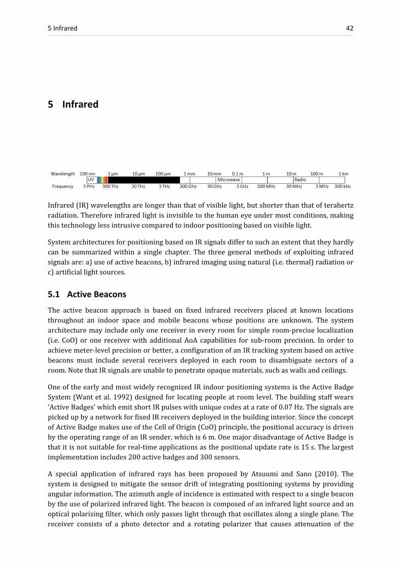
5 Infrared 42
5 Infrared
Infrared(IR)wavelengthsarelongerthanthatofvisiblelight,butshorterthanthatofterahertzradiation.Thereforeinfraredlightisinvisibletothehumaneyeundermostconditions,makingthistechnologylessintrusivecomparedtoindoorpositioningbasedonvisiblelight.
SystemarchitecturesforpositioningbasedonIRsignalsdiffertosuchanextentthattheyhardlycan be summarizedwithin a single chapter. The three generalmethods of exploiting infraredsignalsare:a)useofactivebeacons,b)infraredimagingusingnatural(i.e.thermal)radiationorc)artificiallightsources.
5.1 Active Beacons
The active beacon approach is based on fixed infrared receivers placed at known locationsthroughout an indoor space and mobile beacons whose positions are unknown. The systemarchitecturemayincludeonlyonereceiver ineveryroomforsimpleroom‐precise localization(i.e. CoO)orone receiverwithadditionalAoAcapabilities for sub‐roomprecision. In order toachievemeter‐levelprecisionorbetter,aconfigurationofanIRtrackingsystembasedonactivebeacons must include several receivers deployed in each room to disambiguate sectors of aroom.NotethatIRsignalsareunabletopenetrateopaquematerials,suchaswallsandceilings.
OneoftheearlyandmostwidelyrecognizedIRindoorpositioningsystemsistheActiveBadgeSystem(Wantetal.1992)designedfor locatingpeopleatroomlevel.Thebuildingstaffwears‘ActiveBadges’whichemitshortIRpulseswithuniquecodesatarateof0.07Hz.ThesignalsarepickedupbyanetworkforfixedIRreceiversdeployedinthebuildinginterior.SincetheconceptofActiveBadgemakesuseoftheCellofOrigin(CoO)principle,thepositionalaccuracyisdrivenbytheoperatingrangeofanIRsender,whichis6m.OnemajordisadvantageofActiveBadgeisthatitisnotsuitableforreal‐timeapplicationsasthepositionalupdaterateis15s.Thelargestimplementationincludes200activebadgesand300sensors.
A special application of infrared rays has been proposed by Atsuumi and Sano (2010). Thesystemisdesignedtomitigatethesensordriftof integratingpositioningsystemsbyprovidingangularinformation.Theazimuthangleofincidenceisestimatedwithrespecttoasinglebeaconbytheuseofpolarizedinfraredlight.Thebeaconiscomposedofaninfraredlightsourceandanopticalpolarizingfilter,whichonlypasseslightthroughthatoscillatesalongasingleplane.Thereceiver consists of a photo detector and a rotating polarizer that causes attenuation of the

5.2 Imaging of Artificial Infrared Light 43
signalintensitydependingonthehorizontalangle.Thephaseofthetime‐varyingsignalisthentranslatedintotheangleofthepolarizingplane.Thisallowsestimationoftheabsoluteazimuthanglewithanaccuracyof2%(orafewdegrees)asfirstexperimentshaveshown.Notethatthistechniqueuses a specialmeasuringprinciple that is not related to theAoA (Angle of Arrival)method.
5.2 Imaging of Natural Infrared Radiation
In the literature, positioning systems using natural infrared radiation are known as passiveinfraredlocalizationsystems.Sensorsoperatinginthelongwavelengthinfraredspectrum(8µmto15µm,alsoknownasthethermographyregion)areabletoobtainacompletelypassiveimageof the surroundingworld fromnatural thermalemissions.Thus, it isnotnecessary toemployactiveinfraredilluminatorsoranyotherdedicatedthermalsource.Thermal infraredradiationcanbeusedtoremotelydeterminethetemperatureofpeopleorobjectswithoutanyneed forwearingtagsoremitters.Existingthermaldetectorsarethermalcameras,broadbanddetectors(GolayCells),pyroelectricinfraredsensorsusedformotiondetectionorthermocouplesusedtoconvert heat gradients into electricity or to measure the temperature contact‐free. As adrawback,passiveinfraredapproachesarecompromisedbystrongradiationfromthesun.
Hauschildt and Kirchhof (2010) propose a localization system based on passive thermal IRsensors to detect thermal radiation of the human skin. Their thermal IR approach usesthermophiles, which are a series of thermocouples (i.e. temperature sensor elements)with alowerresolutioncomparedtoIRcameras.Multiplesensorsareplacedinthecornersofaroomfrom where the angles relative to the radiation source are measured. The position is thenroughlyestimatedviatheprincipleofAoA.Viatriangulationfrommultiplethermophilearraysthepositionofhumanscanbedetermined.Firstexperimentsindicatethatpositionalaccuracyatdecimeterlevelisfeasible,buteffectsofdynamicbackgroundradiationneedtobestudiedfirstbeforethemethodisapplicableinrealenvironments.
Ambiplex(2011)offersthesystem‘IR.Loc’thatincludesdifferentlocalizationsolutionsbasedonnaturally emitted heat radiation. A sensor measures the angle of incidence to a heat source.Frommultiplesensorsmountedonthewalls,thelocationofaheatsourcecanbedeterminedatameasurementrateof50Hz.Thereportedlocationaccuracyis20cmto30cmatanoperatingrange of 10m. Intended applications for IR.Loc are in the area of person detection such ascontrolofautomaticdoors,detectionofpersonsinsecurityzonesorsurveillancetoreducetheriskoffire.
5.3 Imaging of Artificial Infrared Light
Optical IR indoor positioning systems based on active IR light sources and IR sensitive CCDcameras are a common alternative to optical systems operating in the visible light spectrum.Implementations using IR cameras are either based on active infrared LEDs such as that ofBoochsetal.(2010)orbasedonretroreflectivetargets,e.g.LeeandSong(2007),AICON(2011)andHagisonic(2008)withtheirStarGazersystem.MoredetailsoncamerasystemscanbefoundinChapter4.
Themotion sensingdeviceknownasKinectused for thevideogameconsoleXbox (MicrosoftKinect 2011) uses continuously‐projected infrared structured light to capture 3D sceneinformationwithaninfraredcamera.The3Dstructurecanbecomputedfromthedistortionofa

5 Infrared 44
pseudorandompatternofstructuredIRlightdots.Peoplecanbetrackedsimultaneouslyuptoadistanceof3.5mataframerateof30Hz.Anaccuracyof1cmat2mdistancehasbeenreported.ThereleaseofaKinectsoftwaredevelopmentkithasinspiredseveralthirdpartydevelopmentsforautomatictracking,roboticguidanceandgesturecontrolandevensurgicalnavigation.TheNorthStarsystemdevelopedbyEvolutionRobotics(2010)isalsobasedonprojectionofinfraredlaserspots.OnlytwoprojectedspotsareemployedbyNorthStartodeterminethepositionandorientationofavacuumcleaner.
5.4 Summary on Infrared Indoor Positioning Systems
Thespectralregionofinfraredhasbeenusedinvariouswaysfordetectionortrackingofobjectsorpersons.SystemsbasedonhighresolutioninfraredsensorsareabletodetectartificialIRlightsourcesatsub‐mmaccuracy,whereassystemsbasedonactivebeaconsor thoseusingnaturalradiationaremainlyusedforroughpositionalestimationordetectingthepresenceofapersonin a room. Some performance parameters of infrared‐based indoor positioning systems arequantifiedinTable5.1.
Table5.1Positioningsystemsbasedoninfrared
Name Year Measuring
Principle
Reported
Accuracy
Coverage Target Illumination Update
Rate
Market Maturity
Active Badges (Want) 1999 cell of origin 6 m scalable signal transmission 0.1 Hz product
Atsuumi 2010 polarized light 2 % 3 m photo detector high demonstrator
Hauschildt 2010 angle of arrival dm 30 m2 natural IR radiation ‐ demonstrator
Ambiplex 2011 angle of arrival 20‐30 cm 10 m natural IR radiation 50 Hz product
Boochs et al. 2010 IR camera 0.05 mm 4 m3 active, LED ‐ development
Lee and Song 2007 IR camera dm 36 m2 retro reflective 30 Hz development
AICON ProCam 2011 IR camera 0.1 mm vehicle retro reflective 7 Hz product
Hagisonic ‐ StarGazer 2008 IR camera cm ‐ dm scalable retro reflective 20 Hz product
Evolution Robotics 2010 IR camera cm ‐ dm 36 m2 IR projection 10 Hz product
Kinect 2011 structured light 1 cm 3.5 m passive 30 Hz product

6.1 Tactile Systems 45
6 Tactile and Combined Polar Systems
TactileandCombinedPolarSystemsareprimarilyusedforindustrialorsurveyingapplicationssince they fulfill demanding accuracy requirements in the orders of 10‐5to10‐6. Despite thisexcellentperformance,whichtranslatesinto0.1mmto0.01mmpositionalaccuracywithinthespecifiedoperatingrangeofafewmeters,thesesystemshavenottraditionallybeenconsideredas ‘indoor positioning systems’. This is due to their high price, which is not suited for massmarketapplications.Researchinthisfieldisconductedbygeodeticinstitutesandmanufacturersofinstruments.Publishedpapersfocusmainlyoncalibrationorassessmentofsuchinstruments.Table 6.1 shows an overview of the instrumentation used for high‐precision 3D indoorpositioningandtracking.
6.1 Tactile Systems
Tactilesystemsarehighprecisionmechanicalinstrumentswhichmeasurepositionsbytouchinganobjectwithacalibratedpointer,aso‐calledprobe.
6.1.1 Measuring Arms
Measuring arms aremanually operated devices designed for short‐range indoor applications.The objective is determination of the pose of a probe or the position of a laser triangulationscanner,representingtheendofanopen‐chainstructurewithqlinksconnectedtoeachotherbyq‐1 joints.Uptoq=7 linksareused.Highprecisionangleencoders inthe jointsmeasuretheorientationofthenextlink.Thecoordinatesofthetiparedeterminedfromthejointanglesandwell‐calibratedlengthsofthejointswhichformapolygonalchain.Forthepurposeofadetaileddigital3Dacquisitionandrepresentationofanobject’ssurface,thetipofthemeasurementarmcanbecombinedwithalaserscanner.Themainadvantagesofmeasuringarmsareportability,highprecisionandahigh(m‐1)degreeof freedomwhich facilitates itsmanualoperation.Theoperatingrange is typically3m,butcanbescaledbycombiningmeasurements frommultipleinstrument stations. Manufacturers of measuring arms are CogniTens, Hexagon Metrology,Romer,Faro,NikonMetrology,CAM2andothers.
6.1.2 Coordinate Measuring Machines
A Coordinate Measuring Machine (CMM), sometimes referred to as measuring robot, isstationarydevice forveryprecise3Dpositioningdetermination.ACMMconsistsof a tableonwhichtheobject tobemeasuredisplacedandamovablebridgewithameasuringprobe.Theprobesamples the testobjectalong thex‐,y‐, andz‐axesof theCartesianmachinecoordinatesystemwithextremelyhighaccuracyintheorderof10‐6to10‐8.Traditionally,mechanicaltouchprobeshavebeenused,whereasnewprobingsystemsarenon‐contactopticalprobes.Optical

6 Tactile and Combined Polar Systems 46
gratingsrunningalongthelengthofeachaxiscanbeusedtodeterminethepositionalongascalesystem.Theworkspace is limitedto thesizeof theCMM, typicallycoveringvolumesbetween(0.3m)3and10m×4m×3m.Aswithmeasuringarms,ascanningdevicecanbemountedonthe tip for a detailed acquisition of the physical geometrical characteristics of an object.Operation of CMMs can be carried outmanually or automatically by direct computer control.Manufacturers includeMetris,Merlin, Leitz, Brown& Sharpe, LT,Mitutoyo, LeaderMetrologyandWalter.
6.2 Combined Polar Systems
PolarsystemsmeasureanglesbymechanicaloropticalencodersorbytheTimeofArrival(ToA)of a rotating beam, e.g. iGPS 6.2.6. In addition to angles, the distances to targets are alsomeasuredsuchthatcombinedpolarsystemsdetermineobjectpositions fromthecomplete3Dvectorbetweeninstrumentandtargetobject.
6.2.1 Laser Trackers
Modernlasertrackersaredevicesequippedwithatelescopeandamultitudeofsensors,whereaninterferometerandtwoangleencodersarethekeycomponents.Thelaserinterferometerisused for distance measurements to a tracking reflector. Nowadays absolute distance can beobserved by an absolute interferometer. The spatial orientation of the emitted laser beam isdetermined by two angle encoders which measure horizontal and vertical positions of therotation axes of a leveled instrument. From distance and angle observations, spherical 3Dcoordinatescanbedeterminedwithaccuracyintheorderof1·10‐6forhigh‐dynamicandhighprecision applications such as for automotive and aerospace industries. A typical operatingrange is 15m, expandable to 80m. Distances can bemeasuredwith an accuracy of 10μm +5ppm(μm/m)andanglesupto0.001”.Thetrackingretroreflectorcanbeequippedwithtactiledevices forprobingor lasers forobjectscanning.Modernlasertrackerscandeterminethefullpose(6DoF)oftheprobebyintegrationofahigh‐speedcamerasystem.Fordynamictracking,the system is capable of closed‐loop control by following the target automatically,where thecurrent position of the survey beam ismeasured by a Position Sensitive Device (PSD). LasertrackersareofferedbyHexagonMetrology,FaroandAutomatedPrecisionInc.
6.2.2 Totalstations and Theodolites
Totalstationsareusedforvarioustasksinthefieldofindoorandoutdoorsurveyingengineering.Usually, a reflector prism is manually or automatically sighted through the crosshairs of atelescope.Horizontal and vertical angles are thenmeasured visually or optically bymeans ofprecisereadingsofdigitalbar‐codesonrotatingdiscswithintheinstrument’salidade.Referenceto the plumb line is established by a two‐axis tilt sensor. In combination with an ElectronicDistance Meter (EDM), relative 3D coordinates of the prism can be determined. Moderntotalstations featureanAutomaticTargetRecognition(ATR)systemandaservomotorcontrolsystemforautomaticprismtrackingandroboticguidance.Nowadays,trackingtotalstationscanbe used to measure real‐time 3D trajectories of moving targets within an accuracy of a fewmillimeters(KirschnerandStempfhuber2008).
Incontrasttototalstations,theodolitesdonotincludeadistancesensor.Twotheodolitescanbeemployed as an ‘industrial measurement system’ to determine 3D coordinates solely fromangularmeasurementsundertheassumptionthatthebaselinevectorbetweenthetwostationsisknown.Bytheuseofanindustrialmeasurementsystem,acoordinateaccuracyof0.1mmcanbereachedwithindistancesof10m.

6.2 Combined Polar Systems 47
Themaximaloperatingrangeofatotalstationistypically2kmto10km,dependingontheEDMand the prism. Despite these performance parameters, totalstations are not associated withindoor positioning, due to high hardware costs, hardware size and need for LoS betweeninstrumentandtarget.LeadingmanufacturersoftotalstationsareTrimble,HexagonMetrology(LeicaGeosystems),TopconandSokkia.
6.2.3 3D Disto
LeicaGeosystems(2011)hasdevelopedalow‐costtotalstationforindoorapplications.Theso‐called ‘3D Disto’ combines a laser projector, a laser distance meter, horizontal and verticalgoniometers,tiltmetersandacamerawithinoneinstrumentwhichcanbeplacedonatablewitha self‐leveling function. The laser projector is used to project laser patterns on the walls forsettingout.The3DDistoisdesignedtoassistplumbers,buildingmanagersorroofers.
6.2.4 Laser Scanners
Terrestrial laser scanners are based on a non‐contact ranging technology for 3D pointmeasurementand3Dpointcloudacquisition.Incombinationwithreadingsatahorizontalandavertical circle, primarily polar coordinates of the measured points are determined and thentransformedintoCartesiancoordinatesystem.Thisprocessgeneratesaso‐calledpointcloudofthescene.Themainprinciples fordistancedeterminationareoptical triangulation,phaseandpulsemeasurements.Fromasingleinstrumentsetupcloserangescanningallowscapturinganarealessthan100mandupto3kmifalongrangescannerisused.Scansfrommultiplestationscanbecombinedviaregistration,makinglaserscanningascalabletechnique.
Manufacturersare–amongstothers–Sick,Faro,Zoller+Fröhlich,Riegl,Callidus,Mensi,Optech,Leica,VisImageandMensi.AnoverviewofterrestriallaserscanningisprovidedinFröhlichandMettenleiter(2004).
Khoshelham (2010) presents an indoor localizationmethod for terrestrial laser scanners viamatchingplanarobjects (suchaswalls) inmultiple scans. If at least threecorrespondencesofintersectingplanescanbefoundintwoscans,relativescannerpositionscanbedeterminedwithan accuracyof a fewcentimeters. Thismethod is useful for theprocessof fine registrationofmultiplescans,butitisnoreal‐timemethodforindoorpositioningduetolongacquisitiontimesrequiredforcapturinglarge3Dpointclouds.
Kokeisl (2011) offers a laserscanning based navigation and collision avoidance system forindustrial robots. The position reference is obtained relative to the environment. Fromautomaticscanstheenvironmentismappedandthenavigationpathisadjustedaccordinglyincaseofobstacles.Anaccuracyof1cmatspeedsof1.5m/sisreported.
6.2.5 Laser Radar
Laserradar,knownasFrequencyModulatedCoherentLaserRadar(FMCLR)usestheprincipleof laser scanning, by sending an infrared laser beam to a target object where the signal isreflectedandafractionofitisreturned.Incontrasttolaserscanning,apartofthebeamtravelsthroughacalibratedopticalfiberforreference.Thetworeturningbeamsaresuperimposedbynon‐linearmixing (heterodynedetection).This technology allows forprecisemeasurement oftheabsolutedistance.Upto2000pointspersecondcanbemeasured.Laserradarscanbeusedat a surface reflectivity of less than 1% and operate independent of lighting conditions. Themain application is the inspection of large volume parts for aerospace and shipbuildingindustries.AmanufacturerisNikonMetrologyandaretailerisQuamtEngineering.

6 Tactile and Combined Polar Systems 48
6.2.6 iGPS
iGPS(indoorGlobalPositioningSystem)isalaser‐based3Dmeasurementsystemwhichcanbeused for high precision industrial measurements. Its name ‘iGPS’ is misleading, because themeasuringprinciple isdifferent from itsspace‐basedcounterpartGPS. iGPSconsistsof twoormorestatictransmitterswhichcontinuouslysendouttworotatingfan‐shapedlaserbeamsandareferenceinfraredpulse(seeFigure6.1).BasedonTimeDifferenceofArrival(TDoA)betweenthe three signals, the relative horizontal and vertical angles with respect to a receiver aredetermined.Inordertoestablishatime‐dependencybetweenthearrivalofthelaserplanesandtheverticalangle,therotationaxisofthelaserplanesaretiltedbyanelevationangleofαel=30°.Thefirstlaserplanefollowsthesecondata90°angledelay(oneplaneistilted30°totheleft,theother 30° to the right). Thehorizontal angle to a receiver is estimated fromTDoAbetween alaserplaneandthereferencepulse.Areceiver’s3Dpositionisdeterminedfromtwoanglesofatleast two orientated transmitterswhose coordinates have been determined in a prior set‐upphase. One can say that iGPS is based solely on triangulation, or more precisely on spatialresection.Thesystemscaleisintroducedfromthefixedlengthbetweentworeceiversasshownin Figure 6.2. Two receivers mounted on a fixed stick (the so‐called vector‐bar) allow fordeterminationofthestick’sfullpose(6DoF).
Figure6.1LaserplanesofiGPS.GraphicbySchmittetal.(2010), originfromNikon.
Figure6.2 iGPSscaledetermination,bySchmittetal.(2010),originfrom
Nikon
Themanufacturer (NikonMetrology2011) states that the accuracyof 3Dpositions is 0.2mmanda typicalmeasurement footprintbasedon4to8 transmitters is1200m2.AmoredetailedassessmentofthesystemisprovidedbySchmittetal.(2010).
Duetotherotationalspeedofthelaserplanes(40Hzto50Hz)andanupdatedrateforreceiverpositions at 40Hz, iGPS can be used for kinematic tracking. Depenthal (2010) assessed theperformance under kinematic conditions and concluded that the dynamicmode enables real‐timetrackingofreceiversatvelocitiesof3m/sand3Dpositiondeviationsoflessthan0.3mm.

6.3 Summary on Tactile and Combined Polar Systems 49
6.3 Summary on Tactile and Combined Polar Systems
Tactileandcombinedpolarsystemsprovideμmtommlevelaccuracy,outperformingallothertechnologies presented in this work. Due to high instrument costs and limitation to a singleroom at a time, these systems are rarely applied to navigation, but are essential tools forindustry, surveying and 3Dmodeling. The key performance parameters of these instrumentsusedingeodesyandmetrologyarequantifiedinTable6.1.
Table6.1Tactileandcombinedpolarsystemsusedforgeodeticandindustrialapplications
Device Typical
Accuracy
(m)
Measuring
Range (m)
or Area (m2)
Measuring Principle Application Typical
Hardware
Costs
Market
Maturity
measuring arm 15 μm + 10 ppm 3 m polygonal chain object inspection > 30.000 € product
CMM 2 μm + 0.4 ppm 10 m × 3 m mechanical, interferometry automotive, inspection size depend. product
laser tracker 10 μm + 5 ppm 80 m distance & angular meas. automotive, aerospace > 110.000 € product
totalstation 2 mm + 5 ppm > 2000 m distance & angular meas. surveying, multipurpose 10.000 € product
laser scanner 3 mm + 5 ppm < 1000 m distance & angular meas. 3D modeling 50.000 € product
3D Disto 2 mm 50 m distance & angular meas. setting out, plumbing 8.000 € product
laser radar 15 μm + 5 ppm 120 m distance & angular meas aerospace, industry 250.000 € product
iGPS 0.2 mm 1200 m2 TDoA, resection industry, metrology > 60.000 € product
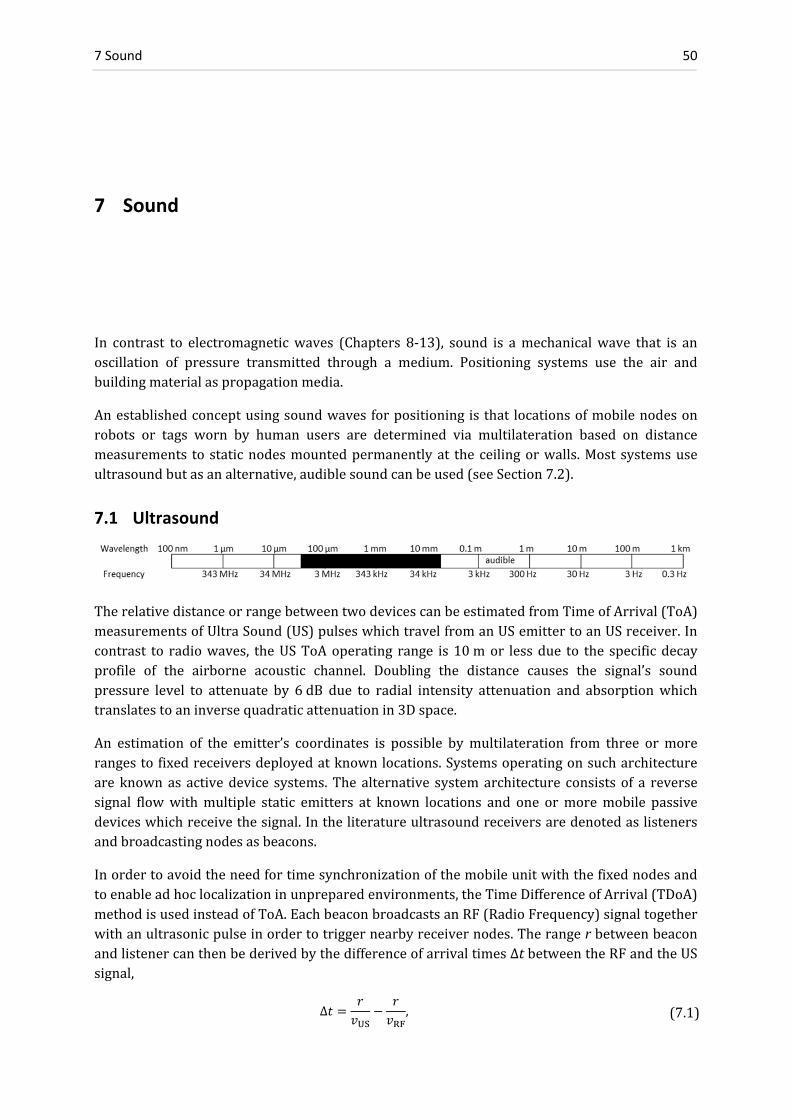
7 Sound 50
7 Sound
In contrast to electromagneticwaves (Chapters 8‐13), sound is amechanicalwave that is anoscillation of pressure transmitted through a medium. Positioning systems use the air andbuildingmaterialaspropagationmedia.
Anestablishedconceptusingsoundwavesforpositioningisthat locationsofmobilenodesonrobots or tags worn by human users are determined via multilateration based on distancemeasurements tostaticnodesmountedpermanentlyat theceilingorwalls.Most systemsuseultrasoundbutasanalternative,audiblesoundcanbeused(seeSection7.2).
7.1 Ultrasound
TherelativedistanceorrangebetweentwodevicescanbeestimatedfromTimeofArrival(ToA)measurementsofUltraSound(US)pulseswhichtravelfromanUSemittertoanUSreceiver.Incontrast to radiowaves, theUSToAoperating range is10mor lessdue to the specificdecayprofile of the airborne acoustic channel. Doubling the distance causes the signal’s soundpressure level to attenuate by 6dB due to radial intensity attenuation and absorptionwhichtranslatestoaninversequadraticattenuationin3Dspace.
An estimation of the emitter’s coordinates is possible bymultilateration from three ormorerangestofixedreceiversdeployedatknownlocations.Systemsoperatingonsucharchitectureare knownas activedevice systems.Thealternative systemarchitecture consistsof a reversesignal flowwithmultiple static emitters at known locations and one ormoremobile passivedeviceswhichreceivethesignal.Intheliteratureultrasoundreceiversaredenotedaslistenersandbroadcastingnodesasbeacons.
Inordertoavoidtheneedfortimesynchronizationofthemobileunitwiththefixednodesandtoenableadhoclocalizationinunpreparedenvironments,theTimeDifferenceofArrival(TDoA)methodisusedinsteadofToA.EachbeaconbroadcastsanRF(RadioFrequency)signaltogetherwithanultrasonicpulseinordertotriggernearbyreceivernodes.TherangerbetweenbeaconandlistenercanthenbederivedbythedifferenceofarrivaltimesΔtbetweentheRFandtheUSsignal,
Δ , (7.1)

7.1 Ultrasound 51
wherevUS≃344m/s is thespeedof sound in theairandvRF≃3·108m/s thespeedof light.BecauseRFtravelsabout106timesfasterthanultrasound,thetraveltimeoftheRFsignalcanbeneglected. The most critical influence on the sound speed vUS is the temperature T. Thedependencyis
331.3 0.606 ∙ m ∙ s , (7.2)
whereT is the absolute temperature in Celsius (°C). At room temperatures this effect causesabout 0.2% systematic range deviation per degree Celsius. For a typical maximum range of10m,achangeof1°C in the temperaturecausesadeviation in therangeestimationof2mm.Therefore,mostultrasoundsystems includesensors forautomatic temperaturecompensation.Nevertheless,thetrueairtemperaturealongthepathbetweentransmitterandreceiverremainsunknown.Minorinfluencesonthespeedofacousticsoundaretheairpressure,theCO2contentandthesoundamplitude.Temporalchangesinthespeedofsoundcanalsobecompensatedbytakingintoaccountcalibrationmeasurementsbetweenknownnodes.
Applications of positioning systems based on ultrasound are indoor tracking of people andmobiledevices,butthesesystemsarerarelyusedinoutdoorenvironmentsduetothefollowingthree reasons:Temperature gradients are larger outdoors and thereforemore complicated tomodelorcompensate.Secondly,winddegrades thesystemprecisionsignificantly.Thirdly, thetypical limitation for distance measurements of about 10m is not practical for outdoor use.Although ultrasound systems are scalable by adding further fixed nodes, the deployment ofnodesinoutdoorenvironmentsisproblematicduetotheabsenceofceilingsornearbywalls.
Further challengesofultrasound systemsaremitigationofmultipathpropagation (Mautz andOchieng 2007) and detection of heavilyDoppler‐shifted signals (Alloulah andHazas 2010). Apracticalchallengearisesfromthetaskofminimizingthebatterydrainthatwirelessultrasonicsystems usually face. Therefore power‐saving techniques have been implemented. Anothernegativeinfluenceonrangingaccuracyisthenear‐farproblemoftransmitters(seeChapter12)andthedirectivityofthetransducers(HazasandHopper2006).
Inordertomakealistener‐beaconsystemfunctional,thecoordinatesofthestaticnodesneedtobe known in advance. Therefore the static nodesneed to be surveyedby another positioningsystem. Because the accuracy of the node coordinates should be at least as good as theultrasound positioning system itself, time‐consuming manual positioning methods such astotalstationmeasurementsarerequired–deliveringapositioningaccuracyof5mmto10mm(1σ).Inordertoavoidtheuseofasecondpositioningsystemforstaticnodelocalization,MautzandOchieng(2007)haveimplementedanauto‐localizationalgorithm.AsshowninFigure7.1,adynamic sensor node is moved slowly to various locations in a room while permanentlycollectingToArangingdatatoatleastfourbeaconnodesmountedattheceiling.Themobileandthestaticnodepositionsareunknown.Eventheinter‐beaconrangesmaynotbeavailableduetoobstaclesbetweenthem.
Thedescribedscenarioneverthelessallowscreationofarigiddistancenetworkbasedonlocalcoordinates.Thedeploymentofstaticnodesinthefourcornersofaroomallowsthesetupofameaningful local coordinate systemorientated along theorthogonalwalls. The redundancyofsuchanauto‐localizationproblemin3Disgivenby
reduncancy 3 6, (7.3)

7 Sound 52
wherenristhenumberofobservedranges,nsthenumberofstaticnodesandnmthenumberofmobile positions. If direct line of sight conditions allow all combinations of ranges to beobtained,thennr=ns∙nmholds.
InFigure7.1, themobilenodehascollected4ranges to4staticnodesat6different locations.For the 3D case, there are 3∙(ns+nm) = 30 unknown coordinates and nr=ns∙nm=24 rangemeasurementscreatinganetworkwitharedundancyof6.Buttakingintoaccountthe6degreesof freedom(i.e.3 translationsand3 rotations) for therigid3Ddistancenetwork, the solutionhas no redundancy for this case. Mautz and Ochieng (2007) have shown that zero or lowredundancy of the network causes the auto‐localization algorithm to fail under real fieldconditions.Withtoolowredundancy,grosserrorsinthepositionestimationarelikelytoremainundetecteddue to the existenceof outlierobservations, badgeometric constraints anderrorscausedbylinearizationoftheobjectivefunction.Toobtainthebeaconcoordinatesthefollowingprocedurecanbecarriedout:
a) Stepwisemovementofthemobilenodeinaroomwhilecollectingrangemeasurements.b) Groupingoftherangesatmmobilepositionsaccordingtotheirtimestamps.c) Grosserrordetectionby findingsudden jumps in therangemeasurementsandtesting
triangleconditions.d) Creation of a distance matrix between all network positions with size (ns+nm) by
(ns+nm),seeFigure7.2.e) Filling the gaps of the distance‐matrix by interpolation. This step establishes rough
approximationsforallinter‐nodalranges.f) Setting up a local coordinate system based on the inter‐nodal ranges of four nodes
(preferablystaticnodes).g) ComputationofallcoordinatesbasedonMulti‐DimensionalScaling(MDS),alocalization
methodwhichtransformsadistancenetworkintogeometricembedding.Givenasetofpairwisedistancesinpresenceoflargerangemeasurementnoise,thelocationapproachusing MDS has outperformed proximity based algorithms (Shang et al. 2004). If therangemeasurementsareofgoodquality,positionscanbedeterminedbymultilateration.
h) Refinement of the coordinates by geodetic network adjustment.When applied to realdata,thenetworkadjustmentmaynotbecarriedoutstraightaway,becauseitrequiresgood approximate values of the unknown positions. In order to avoid a failure of thenetwork adjustment, a heuristic optimizationmethod canbe carriedoutwhich avoidslinearizationbydirectlyusingtheoriginalobservationequations.Theheuristicmethodimprovesapproximatepositionsfortheinputofthenetworkadjustment–typicallyfrommetertocentimeterlevel.AninsightintoheuristicmethodsisgiveninMautz(2002).
Figure7.1Auto‐localizationofstaticnodesusingamobilesensor
Mobile Node
Static NodesCeiling

7.1 Ultrasound 53
s1 s2 s3 s4 m1 m2 m3 m4 m5 m6 s1 s2 not
observed observed
s3 s4 m1 m2 not
observed
m3 observed m4 m5 m6
Figure7.2Distancematrixoftheexamplewith4staticnodesand6mobilepositions
Whentheauto‐localizationprocedurehasbeencompleted, thecoordinatesof thestaticnodesare available in a local system. An over‐determined auto‐location setup allows determiningqualityindicatorsofthecoordinates.
7.1.1 Active Device Systems
Inanactivedevicesystem,mobiledevicesactivelytransmitsignals.Therefore,thetransmissionofultrasonicpulsesneedstobewellscheduledamongthemobiledevices.Thedisadvantageofan active device system is insufficiency in scalability, i.e. if too many users with ultrasonicdevicesgatherinaroom,thechanceofsignaloverlapisincreased.Awell‐coordinatedschemeforpulsetransmissionbetweenthedevicesmaysolvetheproblembutatthecostofareducedmeasurementrate.
Wardetal.(1997)describeanultrasonicsystemnamed‘ActiveBat’whichcanberegardedaspioneer work in the development of broadband ultrasonic positioning systems. Active Batconsistsofroamingtransmittersattachedtotheuserandfixedultrasonicreceiversmountedonthe ceiling. Each transmitter’s position is determined by performing ToFmultilateration. TheActiveBatsystemalsodeducesdirectioninformationbyattachingmultipletransmittersonthemobile object. However, Active Bat employs a centralized system architecture and requiresdense deployment of precisely positioned ultrasonic receivers. The 3D accuracy of asynchronoustransmitteris3cmin95percentofcases.Alargedemonstrationsystemconsistingof720receiversandupto75mobiletagshasbeendeployedinanofficespaceof1000m2.
Inordertomitigatetheproblemofmultipleuserdetectionwhichactivedevicesystemsusuallyface, Alloulah and Hazas (2010) implemented a Code Division Multiple Access (CDMA)despreader on a broadband ultrasonic signal. CDMA allows simultaneous transmission ofdifferentdatastreamsatthesamecommunicationchannel.
Satoetal.(2011)developedarangemeasurementtechniquecalledExtendedPhaseAccordanceMethod (EPAM) which showed a standard deviation of less than 1mm in a laboratoryexperiment. However, the overall position accuracy of the real implementation with tagsattachedtoabodyisreportedas4cm.
Sonitor IPS (2011) is a commercially availableultrasonicpositioning solutionwhichhasbeeninstalledonalargescaleinseveralhospitalsforthepurposeofpatientandequipmenttrackingatroomorsub‐roomlevelaccuracy.Motionactivatedtagswornbytheusertransmitultrasonic

7 Sound 54
signalswithuniqueidentificationcodestowallmountedreceiverswhichprocessthesignalandtransfer relevant information to a central server via LAN or WLAN. The maximum range isspecifiedas18m.
Hexamite (2011) offers ultrasonic positioning systems with various architectural set‐ups.Accordingtothecompanytheproductsaresupposedtoprovideaccuracyof9mmandprecisionof1mmfordistancesupto14m.Astandardevaluationpackagecontains threereceiversandtwotransmitters.Intendedapplicationsareroboticguidance,automationandmanufacturingaswellas3Dfilmstudioassistance.
7.1.2 Passive Device Systems
Passivesystemsrelyonpermanentlyinstalledtransmitterswhichbroadcastultrasoundsignalstothereceivingdevices.Suchanarchitecturehastheadvantagethattheprivacyoftheuserscanbekept.Mobilepassivedevicesonlyreceivesignalsanddonottransmitanything.Thereforethelocalization is exclusively carried out onboard of the device, without any need for networkinteraction.Thenumberofuserscanbescaledwithoutanyriskofsignaloverlapping.
Priyantha (2005) describes in his thesis the passive ‘Cricket’ system developed by the MITLaboratory forComputerScience.TheCricket system ispioneerworkdatingback to theyear2000. A 3D positioning accuracy of 1cm to 2cm can be reached indoorswithin amaximumrangeof10m.Real‐timetrackingisgenerallypossiblewithanupdate‐rateof1Hz.Ahardwareunit can be programmed either as a static beacon ormobile listener. Due to its open systemarchitecture,Crickethasbeenusedasaresearchplatformallovertheworldandinspiredmanyapplications.
Amodern,well‐designedversionofapassivesystemispresentedinSchweinzerandSyafrudin(2010).AlthoughtheprecisionofTDoAdistances isbetterthan0.7mm(empiric1‐σstandarddeviationofrepetitivemeasurements),theabsoluteaccuracyofalocatedlistenerisreportedas1cm.
Jiménez et al. (2009) present the passive device system christened 3D‐LOCUS based on TOFmultilateration and delivering 1cm accuracy. In order to apply pseudo‐random digital codestheyhavechosentouseacoustictransducerswhichoperatemainlyintheaudibleregionbelow25kHz. In order to serve the intended application area of archeological surveying, specialpointingrodswithreceiversatbothendshavebeendeveloped.
7.1.3 Echolocation
Similartobiosonarusedbyseveralanimalssuchasbats,itispossibletoemitsoundpulsesbyatransmitter to the environment and make use of the returned echoes to locate and identifyobjectsorevendeterminethetransmitter’slocation.Theprincipleofbinaural(i.e.two‐receiverbased) localization is illustrated in Figure 7.3. Echolocation systems have the advantage thattheycanoperatewithouttheneedforbeaconsortags.

7.2 Audible Sound 55
Figure7.3Principleofecholocation, graphicby PetteriAimonen(2009)
Reijniers and Peremans (2007) propose a biomimetic sonar system based on distance andbearingestimationofreflectorsusingacentraltransmitterandtworeceiverspointinginslightlydifferentdirections.Asweepingpulseof3msdurationinthefrequencyrangebetween31kHzand59kHzistransmittedandtheechoedsignalisevaluatedinthetime‐andfrequencydomain.First results indicate an uncertainty of the angles of a few degrees and positions of a fewdecimeters.
Wan and Paul (2010) implemented an experimental setup with 6 ultrasonic wall‐mountedtransmitters in order to track personswithout the need for body‐worn tags. An US signal isreflected at a person’s body causing an echowhich is analyzed for estimation of the distancebetweenthepersonandthetransmitter.Frommultiplesensorsit ispossibletodeterminetheperson’s2Dpositionwithanaccuracyofbetterthan0.5m.
7.2 Audible Sound
Asmallfractionofsystemapproachesmakesuseofsoundwavesintheaudiblespectrum.Thekeyideaistomakethesystemeasilydeployableusingsoundcardsofstandarddevices.Apartfromthetaskofavoidingannoyancetotheuser,otherchallengesarise fromlowbitratesanddelayscausedbythesoundcards.
Filonenkoetal.(2010)proposetheuseofinbuiltmobilephonespeakerstogeneratesimplesinetone ultrasonic signals in the near audible spectrum of 17kHz to 22kHz. Their goal is toimplementToFtrilaterationpositioningusingunmodifiedhardwareonordinarymobilephones.

7 Sound 56
Mandal et al. (2005) locate standard mobile devices using audible sounds at a frequency of4kHz.Tominimizeintrusiveness,positioningiscarriedoutonrequestonly.Aftercalibrationofthesedelays,theTOFmultilaterationapproachachieves3Daccuracyof60cm(2σ)witharangeof7m.
7.3 Summary on Sound Systems
Soundsystemsareusedforvarioustrackingapplicationsatcm‐levelaccuracy.Thestrongdecayprofileof acousticwaves causes soundsystems tobe limited toa10moperating range ifnotscaledwith additional nodedeployment. Time synchronization is simple due to the relativelyslowspeedofsound.ThedrawbacksarefrequencychangesduetotheDopplershiftandastrongtemperature dependency. In contrast to other technologies, the performance parameters ofvarious sound systems are relatively similar as shown in Table 7.1. Due to existing NLoSconditions and multipath propagation in indoor environments, the development of reliablesoundsystemsatcm‐levelorbetterremainsasubstantialchallenge.
Table7.1.Localizationsystemsusingsoundwavesandreportedperformanceparameters.
Name Year Reported Accuracy
Active or Passive Devices
Transm
itters
Receivers Tags
or Tag Free
Carrier Fre‐quency
Update Rate
Principle Application Market Maturity
Active Bat 1997 3 cm active 75 720 tags 40 kHz 5 Hz multilateration smart tracking prototype
Alloulah 2010 3 cm active 5 4 tags 20‐50 kHz multilateration AAL, monitoring demonstr.
Sato 2011 4 cm active 5 4 tags 40 kHz 10 Hz multilateration human motion demonstr.
Sonitor 2011 subroom active >99 >99 tags 35‐40 kHz 5 Hz disclosed hospitals, mines product
Hexamite 2011 0.9 cm active >99 >99 tags 40 kHz 30 Hz multilateration 3D studio product
Cricket 2005 1‐2 cm passive 20 >99 tags 40 kHz 1 Hz multilateration smart tracking product
Schweinzer 2010 1 cm passive 5‐6 >99 tags 35‐65 kHz 10 Hz multilateration WSN demonstr.
Jiménez 2009 1 cm passive >5 >8 tags <25 kHz 10 Hz multilateration archeology prototype
Reijiniers 2007 decimeter echo 1 2 free 31‐59 kHz low echolocation robot guidance study
Wan 2010 0.5 m echo 6 1 free 40 kHz 2 Hz body reflection person tracking study
Filonenko 2010 < 1m active 1 1 tags 17‐22 kHz 1 Hz multilateration LBS, guidance proposal
Mandal 2005 60 cm active 1 6 tags 4 kHz request multilateration LBS, malls demonstr.

8.1 Propagation Modeling 57
8 WLAN / Wi‐Fi
WLAN(WirelessLocalAreaNetworks,IEEE802.11standard;‘Wi‐Fi’isusedinterchangeablyorasasupersetofIEEE802.11anddenotestheregisteredtrademarkoftheWi‐FiAlliance)canbeusedtoestimatethelocationofamobiledevicewithinthisnetwork.TheuseofWLANsignalsisa tempting approach, since WLAN access points are readily available in many indoorenvironmentsanditispossibletousestandardmobilehardwaredevices.Therangeof50mto100m which is typically covered by WLAN outreaches that of Bluetooth or RFID. AnotheradvantageofusingWLANisthatlineofsightisnotrequired.ToA,TDoAorAoAmethodsarelesscommon inWLANdue to the complexity of time delay and angularmeasurements. ThemostpopularWLANpositioningmethodistomakeuseofRSSI(ReceivedSignalStrengthIndicators)which are easy to extract in 802.11 networks and can run on off‐the‐shelfWLAN hardware.Therefore,WLANpositioningsystemshavebecome themostwidespreadapproach for indoorlocalization,seeTable8.1foranoverview.Ingeneral,theuseofRSSIincombinationwithWLANcan be subdivided into four strategies: Propagation modeling, Cell of Origin (CoO),Fingerprinting(FP)andmultilateration.
8.1 Propagation Modeling
Modeling of signal propagation is considered as analytical fingerprinting in the literature, buttreatedseparatelyhere.ForthepurposeofanalyticaldeterminationofReceivedSignalStrengthIndicators(RSSI),differentpropagationmodelsareused.AmajortechnicaldifficultyusingRSSIarisesfromthefactthatRSSIvaluesdependtoalargeextentonthepropagationenvironment,making it verydifficult to setup suitablepropagationmodelswhichdescribe the relationshipbetweenRSSIvaluesandreceiverpositioninrealindoorenvironments.Thereforefingerprintingmethods (see 8.3) which rely on simple comparison of empirical measurements withoutapplication of a theoretical model have become the more favorable method compared toanalyticalmodeling.However, analyticalmodeling can be used in combinationwith empiricalfingerprinting.Thebetteratheoreticalmodelcanpredictthemeasurements,thelesscalibrationmeasurementsarerequiredinanofflinestage.
Abasicpropagationmodelistheradialsymmetricfree‐spacepathlossmodel(3.1).Thepurposeofthismodel istoderivethedistancebetweenaradiatingsourceandareceiverbyexploitingthe attenuation of RSSI with distance. However, this simplistic model is rarely applicable inindoor settings where the signals do not attenuate predictably with the distance due to

8 WLAN / Wi‐Fi 58
shadowing, reflection, refraction and absorption by the building structures. The Multi WallModel (MWM) is amodifiedversionof thepath lossmodelwhich takes intoaccount thewallbeingcrossedonthedirectpath.Itrequiresthethicknessofwallsandthedielectricpropertiesof eachwall as input. SinceMWM considers only the direct pathwhich does not necessarilycorrespond to the strongestpath, ray tracing algorithmshavebeenproposedwhich take intoaccount all possible paths and sum up each individual contribution. In order to avoid thecomputationalburdenintrinsictoraytracingParodietal.(2006)usedtheDominantPathModel(DPM)whichtakesonlyintoaccountthestrongestpathwhichisnotnecessarilyidenticaltothedirect path. An accepted propagation is the Indoor Path Loss Model (3.2.8) which has beenvalidated by Chrysikos et al. (2009). However, the success of modeling WLAN propagationindoorsislimitedduetotheinterplayofhighlyunpredictablemultipathfading.
8.2 Cell of Origin
This is a straightforwardmethod suitable for applications with requirements for positioningaccuracies of 50m ormore. TheWLAN access point generating the highest RSSI value at themobile device is identified and the user position is assumed to have the same coordinatepositionastheaccesspoint.
8.3 Empirical Fingerprinting
The empirical fingerprinting approach requires – as a major drawback – a previous set ofcalibrationmeasurementsinanofflinestage(alsodenotedasthecalibrationphase)wheretheRSSI are observed at various locations in the building and stored togetherwith ground‐truthlocationsinadatabaseknownasa‘radiomap’.Eachentryofthedatabaseisdenotedasfinger‐print f and consists of the ground‐truth position (x,y,z) and theRSSI vectorc containing thecalibrationmeasurementstoaccesspoints.ThedatabaseisthenusedintheoperationalonlinestagetoestimatethepositionofamobiledevicebycorrelatingallcurrentRSSImeasurementsrtreceivedattimetfromndifferentaccesspointswiththeRSSIvaluescoffingerprintlocationfstoredinthedatabase.AcommonmethodistodeterminetheEuclideandistance
| , , , (8.1)
in signal space, where the vector of RSSI differences (rt–c) is of dimension n, and n is thenumber of access points. Then, the Euclidean distances dj for allm fingerprint locations aredetermined and stored in the distance vector d. In the most straightforward approach, theminimumEuclideandistancedmin=min(d)toacalibrationpointistakenasthecurrentlocation.Alternatively,thecoordinatesoftheobservationpointcanbecomputedbyaweightedmeanofthecalibrationpoints,wheretheweightsaresetreciprocaltotheirdistancesdj.Forexample,theweightedmeanforthecoordinatexreads
1. (8.2)
Inthesocalledprobabilisticapproaches,thecorrelationvalues

8.3 Empirical Fingerprinting 59
| , , ,∑
, (8.3)
forall j fingerprint locationsarecompared.Basedonthecorrelationvaluecorj theprobabilitythatthecurrentRSSIobservationsrthavebeenreceivedatthesamepositionasthefingerprintfjcanbecomputed.Sincerecordsatanobservationpointcontainmorethanoneepoch,fuzzylogicmethods have been applied tomake use of the additional information (Teuber and Eissfeller2006).
Fingerprinting performance can reach meter‐accuracy, depending on the number of basestationsperm2and thedensityof calibrationpointswhere the fingerprintsare taken.Even iftherearenochangestotheenvironment,recordedRSSIfluctuatesintime.Inordertoeliminatethehigh‐frequencydeviationof attenuation in the signal (knownas fast fading term) theRSSvaluesaretobeaveragedoveracertaintimeintervaluptoseveralminutesateachfingerprintlocation.Owing to the substantial cost incurred by building the radiomap, the fingerprintingapproachmaybeprohibitiveformanyapplications.Inordertomakethecreationofradiomapseconomically efficient, Bolliger (2008), Park et al. (2010) and Hansen et al. (2010) draw onactiveuserparticipationrelyingonthecontributionofendusersbymarkingtheirlocationonafloorplanwhilerecordingthefingerprints.Theamountofpriorfingerprintmeasurementscanalsobeminimizedbyusingmutualmeasurementsbetweentheaccesspointstosetupaninitialpropagationmodelwhichisrefinedbyincorporatingadditionalparametersviaonlinelearning(Parodietal.2006).
ThemaindrawbackofWLANfingerprintingsystemsisthatchangesintheenvironmentsuchasthe moving of furniture in offices, open/closed doors or even people may necessitaterecalculationofthepredefinedsignalstrengthmap.Chenetal.(2005)quantifiedthesedynamicchangesempiricallyandemployedRFIDsensorstogetherwithanonlinecalibrationschemetobuild multiple radio maps under various environmental conditions. Hansen et al. (2010)conclude from long‐termmeasurements over a period of twomonths that static radio mapscannotbeused forroomidentificationeven inmodestlydynamicenvironmentsand thereforerecommenddynamicallyadaptingalgorithms.AlsotheorientationofthedevicescontributestoachangeintheRSSIvalues(Xiangetal.2004)andtheinfluencefromtheuser’sbody(Gansemeretal.2010).Kingetal.(2006)observedadecreaseinthereceptionpowerof15dBmfromtheblockingeffectofahumanbody.EventhehumiditylevelcauseschangesintheRSSI,duetotheWLANoperationbandof2.4GHzbeingaresonantfrequencyofwater(Chenetal.2005).
WLAN hardware and network protocols have not been designed for positioning. As aconsequence,anotherweaknessofWLAN fingerprintingariseswhen themethod isapplied touserswithdifferentWLANchipsets.RSSIvaluescollectedfromdifferentchipsetvendorsdifferin the RSSI definition and are therefore difficult to compare (Koski et al. 2010). Vaupel et al.(2010) determined offsets in the RSSI values of 16dBm between different handheld WLANdevices. Their calibration approach for RSSI offsets takes into account different distances,orientationsandmultipleaccesspoints.Aftercalibration, thesame localizationaccuracycouldbeachievedindependentofthehardwareused.
The indoor localization system RADAR is a pioneer work in WLAN fingerprinting. Bahl andPadmanabhan(2000),whodevelopedthesystem,usedtheK‐NearestNeighbor(KNN)methodinsignalspacefor locationofapersonandachievedamediandeviationof5musing3accesspoints covering about 1000m2. Apart from the node density, their findings include that the

8 WLAN / Wi‐Fi 60
performancedependsonthenumberofdatapointstakenandtheorientationandspeedoftheuser.
Withextensivepre‐calibration(1mgridofcalibrationpoints,110RSSImeasurementsateachcalibrationpoint in8different orientations)King et al. (2006) report an averagedeviationof1.6m.Theirapproachincludestheuseofanadditionaldigitalcompasstodetecttheorientationsof the users to handle blocking effects from the user. The static radio map does not modelenvironmentalchanges.
ThefingerprintingmethodofGansemeretal.(2010)developedanadaptedEuclideandistancemodel which takes into account a dynamically changing environment with changing sets ofreceivedbase stations. Therefore, thedistances in themodel arenormalized according to thenumberofstationsreceived.
In order to make their WLAN fingerprinting system economically feasible for campus‐widedeployment,Gallagher et al. (2010) simplify the calibrationphase,while accepting room‐levelaccuracy. Their system also integrates GNSS measurements and aims to provide indoor andoutdoorlocalizationforstudentsandstaffbasedonsmartphones.
8.3.1 Commercial WLAN Fingerprinting Systems
The XPS WLAN fingerprinting system offered by Skyhook© is a software‐only, server basedsolution which allows determining a mobile position in dense urban areas. Skyhook (2011)buildsupandmaintainsaglobaldatabaseofWLANaccesspointsbycollectingRSSIdatafromspeciallyequippedcars.GNSSandcelltowerID’s(CoO)arealsoused.SincethefingerprintingisdonebySkyhook,positioningcancommenceimmediatelyaftersoftwareinstallation.Thesystemdetermines a device location with 10 to 20 meter accuracy in outdoor environments. Thepositioningperformanceforindoorenvironmentswas30mto70maverageaccuracyinatestmeasurementatavailabilityof50%ofthetime(Gallagheretal.2009).Thesystemisdesignedtoprovideefficientpositioninginformationonalargescale.
Also commercially available is the Ekahau© Real‐Time Location System, based on thecombinationofRSSIWLANfingerprintingandtrackhistory. Incontrast toSkyhook,dedicatedWLANtagsaretobedeployedandtheRSSIdatabaseistobegeneratedbythesystemprovidersthemselves.AccordingtotheEkahau©specifications,WLANtagscanbetrackedat1to3meteraccuracy.Gallagheretal.(2009)stateanaverageaccuracyof7mforindoorenvironments.
8.4 WLAN Distance Based Methods (Pathloss‐Based Positioning)
Informationregardingthedistancefromatransmitteriscontainedinthearrivaltimesandtheamplitudes of the received waveforms. Accordingly, distance estimation using WLAN isgenerallypossiblefromRSSI,ToA,TDoAandRTT.
8.4.1 Lateration Using RSSI
TheRSSIvalueobtainedbyawirelessdeviceisafunctionofthedistancebetweenemitterandreceiver. The path loss or attenuation model (3.1) describes this dependency in general.However,thissimplisticmodeldoesnotfullydescribethedistributionofthepathamplitudesinindoorenvironments,wherethepropagationconditionsareofdynamicnatureduetomultipath(i.e. fast fading) and shadow fading (i.e. slow fading). Taking into consideration fast and slowfadingthemodelbecomes

8.4 WLAN Distance Based Methods (Pathloss‐Based Positioning) 61
4, (8.4)
wherePRisthereceivedpower(RSS)value,PTthetransmittedpower,GTandGRthetransmitterand receiverantennagains,d thedistance,p thepath lossexponent,γ amodelparameter forslowfading(log‐normaldistribution)andhaparametermodelingthefastfading,oftenreferredto as multipath fading. Fast fading appears in the form of small scale rapid amplitudefluctuations of the complex envelope, caused by reception of multiple copies of the signalthroughmultipathpropagationandisusuallymodeledbyRayleighdistributioninabsenceofastrongreceivedcomponent,i.e.NLoSconditions.Incaseswhereastrongdominatingpath(e.g.theLoSpath)existscomparedtootherarrivinglowlevelscatteredpaths,theRiciandistributionis used. More details on the propagation models in indoor environments can be found inHashemi(1993).
If the RSSI are averaged over a certain time interval, the fast fading term h in (8.4) can beapproximated with h=1 and using logarithmic units the dependency between RSSI PR anddistancedbecomes
10 0, , (8.5)
where the shadow fading (also known as slow fading) ismodeled as suggested by Salo et al.(2007)asthezero‐meanGaussianrandomvariablezwithstandarddeviationσ.Shadowfadingrepresentstheslowvariationinthesignalamplitudeduetoobstaclesinthepropagationpaths.Thetermα contains theaveraged fast fading, the transmitterpowerPTaswellas theantennagains GT and GR. Equation (8.5) can be used in any indoor environment to describe therelationship between RSSI values and the distance between an access point and a receiver.Figure 8.1 shows the logarithmic trend and also demonstrates that due to the logarithmicdependency, range estimation becomes more difficult with the increase in distance, i.e. longdistancesarealmostindistinguishablefromRSSI.
Figure8.1DependencybetweendistanceandRSSI.Thecontinuouslinerepresentsthelog‐distancemodel
andthedotsaremeasurementsaccordingtoLaitinen(2004)

8 WLAN / Wi‐Fi 62
ThemainchallengesforWLANRSSIindoorpositioningmethodsarethehightime‐variabilityofsignalstrengthandthecomplexityofmodelingthesignalpropagationaccordingtoattenuationpatternsinindoorenvironments.
Mazuelas et al. (2009) use relation (8.5) to derive distance estimates from RSSI values tomultiple WLAN access points in order to determine the location of a mobile receiver. Tominimizethedirectionaldependencyofpowertransferredfromtransmittertoreceivercausedby the rotational position of the antenna, omnidirectional antennas have been used. Prior tocarryingoutpositioning,theaveragedfadingtermαandthepathlosspweredeterminedforaspecific indoor environment. Using an over‐determined set of distance estimates for theirmultilateration approach, the redundancy was exploited to dynamically adjust the path lossexponents by least‐squares minimization and also quantify the standard deviation of thedeterminedpositionestimatebasedontheresiduals.Mazuelasetal.achievedameanpositionalaccuracyof4mintheirtestmeasurements.
8.4.2 WLAN ToA
WLANToAbasedontrilaterationconstitutesatechnologytoovercometheofflinetrainingphaserequiredbyRSSIbasedtechniques.TimingmeasurementsalsoprovideamorestablealternativecomparedtoRSSImeasurementswiththeirknownvariabilityintime.
However, ToA observations are not directly available from a standard WLAN interface. Thepresent WLAN standard does not provide timestamps with sufficient resolution in time.Assumingoptimalconditions it ispossibletoaccessatimebaseof1µsusingstandardWLAN,which corresponds to a resolution of 300m in distance. This problemmight bemitigated infuturewiththeintroductionofIEEE802.11vwhichhasanallocationfortimestampdifferenceswithintherequest/responsemechanism.
MethodsusingtimedelaymeasurementsinstandardWLANarecomplexduetothedifficultyofobtainingprecisetimingmeasurements.Inordertopreciselydeterminetheimpulseresponse,the distribution of the arrival time sequence has been studied by Hashemi (1993).Muthukrishnan et al. (2006) concluded in their feasibility study that ToA is not a feasibleapproachforlocalizationforWLANduetothelimitationofcurrenthardwareandprotocols.
Forprecisetimemeasurements,itispreferredtokeepthesystemoperatingatthelowestpos‐siblenetworklayersinordertoavoidextradelaysduetoprocessingbetweenthelayers.There‐fore,mostToArangingmethodsrelyonprecisetimemeasurementsatthephysicallayeratthecostofhardwaremodificationsintheWLANchipset.Itshouldbenotedhowever,thattheuseofmodified WLAN hardware is an obstacle for deploying WLAN ToA as practical positioningsolution.
The ToA approach of Golden and Bateman (2007) estimated distances between fixed accesspointsandthelocationofalaptop.Theirapproachrequiresminormodificationstothephysicallayer (software and hardware). In order to mitigate multipath propagation three differentmeasuresare taken.First, adiversity scheme is appliedwhichreliesonanumberofdifferentcommunicationchannels.Secondly,themultipathisminimizedbyusingdirectionalantennasattheaccesspoints.Thirdly,theexistenceofdifferentdelayedpathsinthereceivedsignalistakeninto account by applying the path‐decomposition‐model (3.3). The reported accuracy for thedistancesis1mto5m.

8.4 WLAN Distance Based Methods (Pathloss‐Based Positioning) 63
ReddyandChandra(2007)proposeaToAtechniquebasedoncorrelationof theWLANsignalwherethereceivedsignaliscorrelatedatthephysicallayerwithtrainingsymbolsstoredinthereceiver.Different channelmodelsweredefinedwhich take intoaccount specificpowerdelayprofilestypicalofcertainenvironments,e.g.anofficewithNLoSconditions.Amajordrawbackformeasurements at the physical layer is that specific (nonstandard) hardwaremodules arerequired,causingtheimplementationtobedifficulttoputthroughinreal‐worldapplications.
TheestimationofToAdistancesatupper layersofWLANtakesadvantageof theWLAN(IEEE802.11)standardprotocolandthereforeitsapplicabilityisfacilitatedforrangingusingportable,off‐the‐shelf devices. Due to the limitations of unmodified WLAN hardware and protocols,currentapproachesdetermineToAindirectlyfromRoundTripTime(RTT)rangingtechniques.
8.4.3 WLAN TDoA
TDoArequiressimultaneousreceptionofsignalsfromatleast2accesspointsforthemostbasicoperationmode.OnepremiseofWLANhowever is thatonlyonenode talks at a time, i.e. theaccesspointsdonot transmiton thesamechannel simultaneously.Therefore,TDoAbasedonWLANfollowstheotherapproachwheretheaccesspointsserveasmultiplesynchronizedrecei‐versandthemobilestationtransmitsthesignal.Theproblemisthatneighboringaccesspointsaretypicallysettodifferentfrequencychannelsandlistenonlyinthatparticularfrequency.
8.4.4 WLAN AoA
IEEE802.11n isanamendment to theWLANstandard to improve thenetwork throughputbyaddingatechnologywhichsupportsmultipleantennaconfigurations,knownasMultiple‐InputMultiple‐Output (MIMO).Wonget al. (2008)used this amendmentofWLAN todetermine theAngleofArrival(AoA)ofamobiletransmittersignalreceivedatanaccesspointwithanarrayoffourlinearmonopoleantennas.FromAoAoffouraccesspoints,thepositionofthemobilewasestimated. Based on simulations it was concluded that the potential positioning accuracy isbetterthan2m.
8.4.5 WLAN RTT
The Round Trip Time (RTT) is the time difference between the time a pulse was sent to anaccesspointandthetimetheresponsewasreceivedatthesamedeviceafterreturn(seeSection3.3.3). Inorder toestimateadistance toaWLANaccesspointbasedonRTT, thedelayat theaccesspointmustbeknown.WLANaccesspointshavenodeterministicdelay.Duetovariableinterrupt latenciesoutgoingor incomingtimestampsare falsified.Theresultingdelayshaveatypical variation of 5µs which translates to 1500m error in the distance estimation. Onepossiblesolutionistomeasurethetimedelaydirectlyattheaccesspointandforwardthevalueof the delay to themobile station. In addition, the clock drift of an RTT observationmust betakenintoaccountduringtransmissionofasequence.IfaWLANclockhasafrequencystabilityof50ppmandtheRTTobservationtakes320µs,anaccuracyof5mcanbeassumed.
Günther and Hoene (2004) conducted experiments with WLAN RTT based on low‐cost,commercialWLANhardware(withmodificationsat theMediaAccessControl (MAC) layerbutwithoutmodificationatthephysicallayer).TheyusedtheintrinsicfeatureofWLANthatapingresponse is immediately acknowledged by its receiver to determine indirectly the airpropagation time. By usingmultiple delay observations and applying statistical methods (i.e.stochastic resonance)Günther andHoene found that the propagation delays correlate closelywiththedistance,obtainingadeviationofonlyafewmeters.

8 WLAN / Wi‐Fi 64
Ciuranaetal.(2009)carriedoutapuresoftwarebasedsolutionfortwo‐wayrangingontheIEEE802.11standardprotocolandoff‐the‐shelfWLANhardware.FromtheRoundTripTimeRTTiforadistanceiandthereferenceRoundTripTimeRTT0forthedistancezero,thesignaltraveltime
∆2
(8.6)
canbedetermined.TheRTTisthedifferencebetweentime‐stampsobtainedattheMAClayer.Experiments conducted under LoS conditions showed a large dispersion of RTT values. Afteraveraging1000measurements(equivalenttoadurationof1s),arangingaccuracyof1.7mwasobtained for a LoS indoor distance of 13m. An attempt to reduce the dispersion of the RTTobservationshasbeenmadebyCiuranaetal.(2010).Inordertobecomeapracticalsolutionforindoorpositioning,morehostilescenariosmustbeaddressedandtheimpactofsimultaneouslyinjecteddatatrafficattheaccesspointmustbebetterunderstood.Basedonsimulation,Tapperoetal.(2010)predictthatacampuswideimplementationofaWLANRTTpositioningsystemcanachieveanaccuracyof3mto5m.
8.5 Summary on WLAN Systems
Fingerprinting based on RSSI values is the prevalent method of usingWLAN for positioning.Dependingonthedensityofcalibrationpoints,fingerprintingreachesaccuraciesof2mto50m,seeTable8.1.Thefingerprintingmethodisparticularlyofcommercialinterest,becauseoff‐the‐shelfdevices canbeused.ExperimentsonWLAN time‐of‐arrivaldistancemeasurementshaveproven tobeofpoorqualitydue tomultipathand lowresolutionof theclocks.UsingRSSI fordistance estimation in indoor environments has also proved unreliable due to an irregulardependencybetweenattenuationanddistanceinindoorenvironments.
Table8.1LocalizationapproachesusingWLANandreportedperformanceparameters
Name Year Reported
Accuracy
(m)
Area (m2) per
Access Point.
For non RSS: Type
of Modification
Principle Prior
cali‐
bration
Number of
Calibration
Points
Model / Method Market
Maturity
Parodi 2006 3.3 1235 / 14 = 88 online learning minimal 114 DPM study
Xiang 2004 2 – 5 1400 / 5 = 280 fingerprint & map yes 100 offline training study
Bahl 2000 5 978 / 3 = 326 fingerprinting yes 70 offline training study
Gansemer 2010 2.1 972 / 24 = 40 fingerprinting yes 972 offline training study
Koski 2010 5 – 7 5600 / 206 = 27 fingerprint & map yes 96 coverage area study
Hansen 2010 2 ca. 140/ 14 = 10 fingerprinting yes 17 dynamic model study
Chen 2005 2 – 4 400 / 5 = 80 fingerprint & RFID no online dynamic model study
King 2006 1.6 312 / 20 = 156 fingerprinting yes 166 offline training study
Teuber 2006 2 – 3 400 / 5 = 80 fingerprinting yes 16 fuzzy logic study
Mazuelas 2009 4 3375 / 8 = 422 multilateration no only AP path loss model study
Gallagher 2010 room level unknown fingerprinting yes low signal distance study
Ekahau 2009 7 ca. 450 / 5 = 90 fingerprinting yes ‐ offline training product
Skyhook 2011 30 – 70 ‘global’ coverage fingerprinting no, by Skyhook offline training product
Golden 2007 1 – 5 hardware mod. diversity no ‐ path decomposition study
Reddy 2007 15 hardware mod. time of arrival no ‐ LTS correlation simulation
Wong 2008 2 hardware mod. angle of arrival no ‐ ‐ simulation
Günther 2004 5‐15 software mod. round trip time no ‐ ‐ study
Ciurana 2009 1.7 software mod. round trip time no ‐ line of sight study

8.5 Summary on WLAN Systems 65
9 Radio Frequency Identification
AnRFID (RadioFrequency IDentification) systemconsists of a readerwith an antennawhichinterrogates nearby active transceivers or passive tags. Using RFID technology, data can betransmitted from theRFID tags to the reader (also known asRFID scanner) via radiowaves.Typically,thedataconsistofthetag’suniqueID(i.e.itsserialnumber)whichcanberelatedtoavailable position information of the RFID tag. The most frequently employed positioningprinciple is thatofproximity,alsoknownasCoO(CellofOrigin),e.g. thesystem indicates thepresenceof apersonwearing anRFID tag.Thereby, theaccuracyof anRFID system ishighlydependingonthedensityoftagdeploymentandthemaximalreadingranges.Alternatively,theReceivedSignalStrengthIndicators(RSSI)canbeusedforcoarserangeestimationinordertoapplymultilateration techniques.TimeofArrival (ToA)distanceestimationonRFIDhasbeenprovendifficult to achieve. In order tomeasure the distance between a reader and a tag at aresolutionofbetterthanonemeter,abandwidthofat least10kHzmustbeusedandmultipleobservationsneedtobeaveraged.ThestandardcaseofRFIDpositioningbasedonToAdistancesrelies on observations from a single tag, where the position determination is carried out incombination with Angle of Arrival (AoA) measurements from that tag. Also Phase of Arrival(PoA)methodshavebeenproposed forRFID, seePovalač and Šebesta (2010). Fingerprinting(FP)basedonpre‐measuredsignalmapscanalsobeapplied.Readersareabletoscanseveraltagsathighdataratesupto10Hz.
Generally,RFIDsystemscanbeunobtrusivetotheuserbyintegratingthetagsinthepavement,under the carpet or in the walls without direct line of sight, since the radio waves have theabilitytopenetratesolidmaterialstosomeextent.Thehigherthefrequency,themorethesignalsuffersfromattenuation.ThetypicalfrequencyrangesarecategorizedasLowFrequencies(LF)at30kHzto500kHz,HighFrequencies(HF)at3MHzto30MHz,Ultra‐Highfrequencies(UHF)at433MHz&868MHzto930MHzandmicrowaves(SHF)at2.4GHzto2.5GHz&5.8GHz.
Products equippedwith RFID tags can be tracked seamlessly from a supplier’s factory to theretailer’sstoreshelves.However,asRFIDmovesto itemanddevicetagging, theprobabilityoftags disclosing personally identifiable information has become a primary privacy concern forusers.Ontheotherhand, theunique identificationofRFIDcanbeused forsecurity tocontrolbuildingaccessorforpaymentsystemsallowingcustomerstopayforitemsautomatically.WhenscalinganRFIDsystemtolargenumbersinmultiplefacilitieswithgeographicaldistribution,achallengefordatamanagementandconfigurationarises.

9 Radio Frequency Identification 66
9.1 Active RFID
An active RFID system consists of deployed RFID scanners which interrogate active radiotransceivers equipped with internal battery power. In contrast to passive tags the need forbatteriesmakesactivetransceiversheavierandmorecostly,butenableslongdetectionrangesof 30mormore. The activeRFID technology can be used for positioning,where the locationestimationistypicallycarriedoutbyfingerprintingonRSSI.
Secoetal.(2010)haveachievedamedianpositioningaccuracyof1.5mbasedon71activeRFIDtagscovering55roomsof1600m2.UsingGaussianprocessestodescribethespatialdependenceofRSSI signals propagating indoors they improved the accuracyby 30%versus least squaresminimization.Jiménezetal.(2010)usedtheactiveRFIDtagstostabilizetheIMUdriftofafootmountedpedestriannavigation system.Theirmethodof tight IMU‐RFID integration limits theabsolutedriftdeviationtomaximal1mto3m.Atanemissionfrequencyof1Hz,itisexpectedthatthetags’batterieswilllastforaperiodof6months.
Peng et al. (2011) integrated an active RFID system with INS/GNSS in order to establish aseamless indoor/outdoor positioning system for the purpose of vehicle and pedestriannavigation. Based on a Sigma Point Kalman Filter multi‐sensor integration algorithm, meter‐levelaccuracycouldbeachieved.
Kimaldi (2011) offers a solution for applications in hospitals based on static active readersoperatinginthemicrowaveband.Thetagsarewornaswristbandsorattachedtokeyringsforaccesscontrolandpersonalmonitoring.
9.2 Passive RFID
PassiveRFIDsystemssolelyrelyoninductivecouplingandthereforedon’trequirebatteries.Theprinciple of inductive coupling allows the tags to receive sufficient energy in the form of RFwaves fromthenearbyRFIDscannertotransmittheircodesbacktothescanner.PassivetagscanbeappliedforwaypointnavigationbasedonareferencegridofIDmarkerswhoselocationsare accessible fromadatabase.The advantagesofusingpassiveRFID tags forpositioningaretheir small size, high level of ruggedness, relatively inexpensive installation and lowmaintenance needs since they have no batteries. Therefore, passive tags are suitable forsubsurfaceembeddinginbuildingmaterial.Asthemaindrawback,thedetectionrangeisusuallylimited to2m,whichdemandsdensedeploymentof tags.Theattenuation for embedded tagsincreaseswiththefrequency,e.g.theapplicationforconcreteembeddedtagsisprohibitiveforfrequencies above 2.4GHz. Below 100MHz the attenuation of embedded tags is low andcomparabletothatof freespace,but frequenciesbelow300MHzareunsuitedforreadrangesabove 1meter due to inductive coupling as a phenomenon of near‐field operation. Thepenetrationofelectromagneticwavesinconcretedependsontheuseofintegratedmetalfibers,themoisturecontentofwalls, floorsandceilingsandtheangleof incidenceoftheradiowave.Penaetal.(2003)haveshownthatsignalpropagationthroughreinforcedconcretehasapowerlossof90%at30cmpenetrationdepthandafrequencyof900MHz.
Daly et al. (2010) have embedded passive RFID tags in concrete and optimized the antennadesignwithrespecttoamaximalreadingrangeforpassivetags.Theywereabletodoublethereadability by achieving a reading range of up to 1.2m of concrete embedded tags. TheembeddingofRFIDinthegroundisusedfornavigationbasedonsmartpavingstones.

9.3 Summary on RFID Systems 67
Further applications are discovery and identification of buried pipes. Dziadak et al. (2005)suggest attaching passive RFID tags to buried non‐metallic pipes in order to facilitate theirdetection.
Passive tags have shown to be applicable for vehicle guidance (Baum et al. 2007) aswell asinventorycontrol(Frick2011).
The navigation system ‘ways4all’, developed by Kiers et al (2011) includes arrays of passiveRFID tagswhich have been deployed under the carpet to provide route guidance for visuallyimpairedandblindpeople.Experimentsshow,thatthecurrentmaximalreadingrangeof30cmneedstobeextendedto60cminordertoobtainasufficientlyhightagdetectionrate.
Uchitomietal.(2010)haveenhancedthepureproximitypositioningofanRFIDreaderantennabasedonpassiveRFID tags.They rotate theRFID reader antenna in thehorizontal planeandestimate itsposition fromthe intersectionofpositionsof twocommunicationboundaryareas,see Figure 9.1. Using this method, a robot arm of 1.2m in length could be located with anaccuracyoflessthan20cm.
Figure9.1IntersectionoftwoRFIDantennacommunicationboundariesbasedondifferentrotationangles
accordingtoUchitomietal.(2010)
Another enhancement of passive RFID positioning based on proximity detection has beenimplementedbyFujimotoetal. (2011).Byvaryingthetransmissionpowerof thereader, theycreatedifferentsensingrangestorefinethedistanceestimationofatag.Inaddition,thereaderismovedtodifferentlocationsinordertodetermineitspositionwithhigheraccuracy.Ittakes30secondstodetermineaposition.
FutureShapeoffersthesolutionforrobotnavigationbasedona50cmgridofpassiveRFIDtagswiththeproductnameNaviFloor(2011).Oneapplicationisthatacleaningrobotcanrecordthedateandplaceofitsoperationandevenwhichcleanserwasused.
9.3 Summary on RFID Systems
MostRFIDsystemsrelyonproximitydetectionofpermanentlymountedtags to locatemobilereaders. Therefore the accuracy of an RFID system is directly related to the density of tag
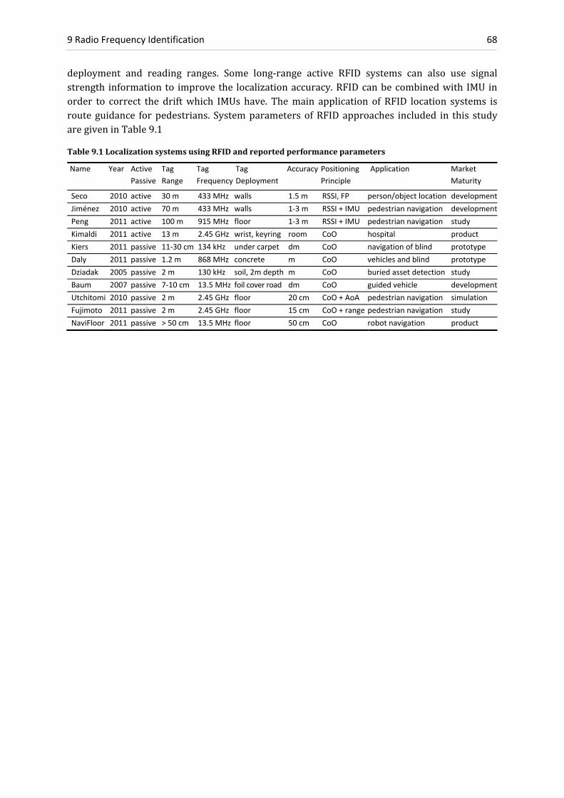
9 Radio Frequency Identification 68
deployment and reading ranges. Some long‐range active RFID systems can also use signalstrength information to improvethe localizationaccuracy.RFIDcanbecombinedwith IMU inorder to correct the driftwhich IMUs have. Themain application of RFID location systems isroute guidance forpedestrians. SystemparametersofRFIDapproaches included in this studyaregiveninTable9.1
Table9.1LocalizationsystemsusingRFIDandreportedperformanceparameters
Name Year Active
Passive
Tag
Range
Tag
Frequency
Tag
Deployment
Accuracy Positioning
Principle
Application Market
Maturity
Seco 2010 active 30 m 433 MHz walls 1.5 m RSSI, FP person/object location development
Jiménez 2010 active 70 m 433 MHz walls 1‐3 m RSSI + IMU pedestrian navigation development
Peng 2011 active 100 m 915 MHz floor 1‐3 m RSSI + IMU pedestrian navigation study
Kimaldi 2011 active 13 m 2.45 GHz wrist, keyring room CoO hospital product
Kiers 2011 passive 11‐30 cm 134 kHz under carpet dm CoO navigation of blind prototype
Daly 2011 passive 1.2 m 868 MHz concrete m CoO vehicles and blind prototype
Dziadak 2005 passive 2 m 130 kHz soil, 2m depth m CoO buried asset detection study
Baum 2007 passive 7‐10 cm 13.5 MHz foil cover road dm CoO guided vehicle development
Utchitomi 2010 passive 2 m 2.45 GHz floor 20 cm CoO + AoA pedestrian navigation simulation
Fujimoto 2011 passive 2 m 2.45 GHz floor 15 cm CoO + range pedestrian navigation study
NaviFloor 2011 passive > 50 cm 13.5 MHz floor 50 cm CoO robot navigation product

9.3 Summary on RFID Systems 69
10 Ultra‐Wideband
Ultra‐Wideband (UWB) is a radio technology for short‐range, high‐bandwidth communicationholding the properties of strong multipath resistance and to some extent penetrability forbuilding material which can be favorable for indoor distance estimation, localization andtracking. A typical UWB setup features a stimulus radiowave generator and receiverswhichcapturethepropagatedandscatteredwaves.Incontrasttonarrowbandoperation,UWBwavesoccupyalargefrequencybandwidth(>500MHz).Moreprecisely,anemittedradiowavebelongstoUWBifeitherthebandwidthexceeds500MHzor20%ofthecarrierfrequency.Inordertoavoidinterferencewithotherradioservices,theFederalCommunicationsCommission(FCC)intheUSAhas limited the unlicenseduse ofUWB to an equivalent isotropically radiatedpowerdensityof‐41.3dBm/MHzandrestrictedthefrequencybandto3.1GHz‐10.6GHz(respectively6.0GHz‐8.5GHzinaccordancetotheEuropeanCommunicationsCommittee(ECC)).Figure10.1illustrateshowUWBcoexistswithotherRadioFrequency(RF)standards.
Figure10.1 RegulatedUWBspectrum
Legalrestrictionsinsignalpowerlimittheoperatingrangetolessthan100m.Ontheotherhandthe low power spectral density prevents harmfulness to the human body and bounds theinterference of UWB signals with other narrowband receivers. Licensed UWB technologiesoperate in thewavelength ofmicrowaves,where the low frequency components in the UWB

10 Ultra‐Wideband 70
signal spectrum have the ability to penetrate building materials such as concrete, glass andwood(Koncuretal.2009).This isausefulproperty for indoorpositioning,because itenablesranging under NLoS conditions and makes inter‐room ranging possible. On the other hand,partialsignalpenetrationintothetargetobjectisunfavorableforprecisedistantmeasurements,because the reflected signal includes multiple returns besides the outer boundary reflection.ThereforerobustextractionofusefulinformationfromthereceivedsignalisamajorchallengeinUWBranging.Superpositionofdifferentscatteringeffectscomplicatesdatainterpretation.
10.1 Range Estimation Using UWB
AmajoradvantageofusingUWBfordistancemeasurementsisthatlargebandwidthtranslatesintoahighresolutionintimeandconsequentlyinrange.Theachievablerangeresolutionrrcanbeapproximatedwith
2, (10.1)
where v is the speed of the wave front and b the bandwidth. E.g. for the FCC band andpropagation in freespace(assumingspeedof lightwithv=c0) it isrr≈0.5c0/7.5GHz=2cm,respectively6cmfortheECCbandatbandwidthb=2.5GHz).
UWB ranging techniques include Time of Arrival (ToA), Two Way Ranging (TWR), TimeDifference of Arrival (TDoA). All these techniques rely on time measurements which can bedividedintothreedifferentprinciplesasdescribedbelow.
10.1.1 Continuous Waves
Withinthefrequencyband,differentfrequenciesaresequentiallyusedbysteppingorsweeping(i.e.frequencymodulationinamannersimilartoachirp,seeFigure13.2).Thesignalisanalyzedinthefrequencydomainresultinginlowtimeresolutionwhichisunfavorablefordynamicreal‐time applications. Continuous waves allow for precise ranging, but cannot be used for smalldevicessuchasasmartphonebecausesuchtechnologyrequireslargeantennas.Ifthefrequencyrangeisverywide,alargephysicalsizeoftheantennaisnecessarytoachievesufficientantennaefficiency.
10.1.2 Impulse Radio
The UWB Impulse Radio (UWB‐IR) is simply structured and can be used for fast distancemeasurements.Thedurationofthepulsesisintheorderofnanosecondsorevenless.Comparedtocontinuouswaves,ultra‐shortpulsesare less likely to interferewithsignals travelingotherpathsallowing forbetterresolutionof the lineof sightpathand thereforeevokingrobustnessagainstmultipath.Sincetheradioshavetobepoweredforashorttimeonlybeforeandduringpulse generation,UWB‐IRhas a lowpower consumption compared to otherUWB techniques.UWBpulse‐basedrangingsystemsareemployedwithrelativelylowrepetitionratesof1MHzto100MHz (i.e.megapulsesper second), in contrast toUWBcommunication systemswhichuse1GHz to 100GHz (Robert et al. 2010). Stoica (2006) presents a demonstrator for UWB‐IRrangingbasedonnon‐coherentenergy‐collectionandachieves1.5m(5ns)distanceestimation.Fischeretal.(2010)useimpulsesof300psduration(equivalentto9cmwavelength)employinga TwoWay Ranging (TWR) technique based on the gated oscillator principle. An accuracy of4cmwasreportedunderperfectLoSconditions.PietrzykandvonderGrün(2010)achievedarangingaccuracyof1cmto2cmforLoSdistancesofupto5mbetweenanUWB‐IRtransmitterandanon‐coherentenergydetectionreceiver.

10.2 Positioning Methods Using UWB 71
An actual implementation for localizing amobile robot in industrial environmentswithNLoSconditions has been carried out by Segura et al. (2010). Four synchronized anchornodes areused to determine the 2D location of a robot within 20cm accuracy by TDoA ranging andhyperbolic intersection. The method also works under NLoS conditions at slightly poorerpositionalaccuracy.
10.1.3 Pseudo Noise Modulation
RandomorpseudonoisecanbeappliedforToAranging(Hermanetal.2010,Zetiketal.2010,Kocur et al. 2009).Usually this technique is basedonMaximumLengthSequences (MLS, alsoknown as M‐sequences) which are pseudo‐random binary sequences (of 585ns duration forexample). As a disadvantage, large processing capabilities are required for determining thecorrelationatthereceiver.Nevertheless,pseudonoisetechniquesareofinterestforthemobilephonemarket,becauseminiaturizedantennascanbeused.
10.2 Multipath Mitigation Using UWB
ThelargesignalbandwidthofUWBallowsforhighresolutionintimesuchthatalargenumberof delayed multipath components appear in the signal and become resolvable. The richmultipathdiversitycanbeusedtomitigatesignalfading.AccordingtoHausmairetal.(2010)itis an ongoing research challenge to extract the multipath components from the informationembeddedintheChannelImpulseResponse(CIR)oftheUWBsignal.Molisch(2009)hasmadeanattempttobetterunderstandtheUWBfadingstatisticsandCIRwhichconsistsofthesumofdelayed,attenuatedandscaledreplicasofatransmittedimpulse.
Coherent receivers are particularly well suited for multipath mitigation. A coherent receiverrecoverstheabsolutephase,amplitudeandtimeofthereceivedmultipathcomponents,whileanon‐coherent receiver uses only the envelope of the signal power by autocorrelation of thereceivedsignal.Sincenon‐coherentreceiversdonotusefrequencyandphase,lessinformationis provided for the separation of multi‐path reflections. Therefore, their ability to detectmultipathislimitedcomparedtocoherentreceivers.
10.3 Positioning Methods Using UWB
10.3.1 Passive UWB Localization
Passive UWB systems have the potential for localization of people and objects from signalreflection, using the principle of radar (Chapter 13.5). The advantage of passive UWB is thatneitheranactivenorapassive tagneedstobewornbytheusernorattachedto the localizedobject. A typical passive localization setup includes one or more omnidirectional emitterantennasandmultiplelistenerantennas,asshowninFigure10.2.

10 Ultra‐Wideband 72
Figure10.2 Passivelocalizationsetup
In order to detect a moving person, time‐invariant direct waves and strong static signalsreflected from furniture need to be subtracted. Given that the locations of the emitter andreceiver antennas are known, estimated ranges from the reflectedwaves canbeused for anyrange‐based algorithm such as ToA orTDoAmultilateration to determine the object position.Following the so‐called background subtraction approach, it is possible to observe extremelysmallmovementssuchascardiacorrespiratoryactivity(e.g.Koschetal.2011).
BasedonexperimentswithanetworkofdeployedUWBpseudo‐noisesensors,Herrmannetal.(2010)haveshownthefeasibilityofUWBforapplicationinAmbientAssistantLiving(AAL).Thetest network consisted of two transmitters and four receivers in one room. From signalreflectionsfromamovingperson,thepropagationdistanceandthereflectivityof thereceivedwavewereusedtodeterminethe locationand identify theactivityof theperson.Theauthorsconcluded that scattering effects at the human body complicate data interpretation. For thepurposeofsmartaudiosystems,Zetiketal.(2010)demonstratedthatpassiveUWBlocalizationhasthecapabilitytodetectwalkingpersonsbyemployingasetupofmulti‐receiverantennas.
10.3.2 UWB Virtual Anchors
Under the assumption that the 3D geometry of a room is known,multipath signal reflectionsfromasingleUWBtransmittercanbeusedforpositionestimationofamobilereceiver.Evenifonly one transmitter has been physically deployed, signal reflections from walls cause pathdelayswhich canbeused toderivepseudodistances to so‐called virtual anchors andperformmultilateration to estimate the transmitter position. Figure 10.3 illustrates the principle ofvirtualanchors.Meissneretal.(2010)proposethevirtualanchormethodincombinationwiththe use of trajectory information. To determine the unknown positions, a multimodaloptimizationproblemissolvedbyaso‐calledstatespaceestimationtechnique.
Moving Person
EmitterEmitter
ReflectedWaves
Receiver Antennas
Direct Waves

10.3 Positioning Methods Using UWB 73
Figure10.3Virtualanchorbasedmultilateration
10.3.3 UWB Direct Ranging
Direct,non‐reflectedUWBrangemeasurementscanalsobeusedforpositioning.Asactivetagsare carried by the mobile user, such approaches can be categorized as active systems.ImplementationscanbebasedonToA,TDoAorRTT(RoundTripTime)distancemeasurementsfrom UWB Impulse Radios (UWB‐IR, see 10.1.2.). Positions are determined based on LoSdistancesbylaterationtechniques.
10.3.4 UWB Fingerprinting
The large frequencyspectrumofaChannel ImpulseResponse(CIR) fromanUWBtransmittercontains a large amount of information originating from multiple multipath components.Therefore,auniquefingerprintcanbeassignedtoeachlocationandstoredinadatabaseduringanofflinetrainingphase.Inanonlinephase,thecurrentCIRiscomparedtothedatabaseandthefingerprintwhichisresponsiblefortheoptimalcrosscorrelationcoefficient isreturnedasthecurrent position. UWB fingerprinting has the potential to achieve better accuracies thanfingerprinting based on WLAN and is also applicable in NLoS scenarios. The advantage offingerprinting using Received Signal Strength Indicators (RSSI) is that the method does notrequire time synchronization. As a drawback, the RSSImethod does notmake use of the fullpotentialofhighresolutionavailablewithUWB.
Kröll and Steiner (2010) implementedUWB fingerprintingwith a grid spacing of 1cm. Theirdemonstrator system consisted of one transmitter, one receiver and 6 fingerprinting regions,each 28cm x 28cm in size. The research team was able to correctly identify each neighborregionandachievedanaveragepositionaccuracyof4cm.
Wanget al. (2010) carriedout fingerprintingbasedonRSSI to localize a staticUWB receiver.Basedonademonstratorsystemsetup,apositional accuracyof0.33mwasreportedafter20fingerprintshadbeentakenfromfourfixedUWBtransmittersonanareaof1.2m×1.6m.
Trans‐mitter
Receiver Antenna
Virtual Anchor
Virtual Anchor
Virtual Anchor
Room

10 Ultra‐Wideband 74
10.4 Commercial UWB Systems
A commercially availableUWB‐IRpositioning solution is that ofUbisense (2011). The systemoperatesinthe6.5GHzto8GHzbandandlocalizessmallsizedactivetagsequippedwithlong‐life batteries. A system setup requires deployment of multiple fixed receivers which includeantennaarraysfortheestimationoftheangleofincidence.Positiondeterminationiscarriedoutby a combination of TDoA and AoA with a specified 3D accuracy of 15 cm for indoorenvironmentsandanoperatingrangeofaround50m.
TheUWB‐IR systemof ZebraEnterpriseSolutions (2011)utilizesTDoA to locate tagsup to adistanceof100mandhasaspecifiedaccuracyofbetterthan30cmunderlineofsiteconditions.Thesystemisparticularlywellsuitedforenvironmentswithseveremultipath.
10.5 Summary on Ultra‐Wideband Systems
SinceachievableaccuracyofToAmeasurements isdirectlycorrelatedtothesignalbandwidth,Ultra‐Wideband iswellsuited forpreciseranging.AtbandwidthsofseveralhundredMHzandappropriatetimeresolutionintheorderofnanoseconds,rangingandpositioningatcm‐levelarepossible.UWBisespeciallyusefulforindoorenvironmentswheremultipathissevere,becausethe wide bandwidth facilitates the detection of multiple time‐delayed versions of a signalsequence.ThereasonwhyUWBhasnotenteredthemassmarket(apart fromafewindustrialimplementations) is the requirement for a dedicated transmitter‐receiver infrastructure. AnoverviewofUWBimplementationsincludedinthisstudyisgiveninTable10.1.
Table10.1.LocalizationsystemsusingUWBandperformanceparametersasreported.
Name Year active /
passive
Transm
itters
Receivers
Noise Radar
or IR (Pulse
Duration)
Principle Application Accuracy Market
Maturity
Robert 2010 active 1 4 IR (1.5 ns) ToA indoor application not reported demo.
Stoica 2006 active 1 1 IR (750 ps) ToA sensor networks 1.5 m demo.
Fischer 2010 active 1 1 IR (300 ps) ToA, RTT industrial application 4 cm demo.
Pietrzyk 2010 active 1 1 IR (65 ps) ToA precise ranging 1 cm – 2 cm demo.
Segura 2010 active 4 1 IR (2 ns) TDoA mobile robot 20 cm prototype
Herrmann 2010 passive 2 4 noise M‐seq. body reflection AAL, monitoring person detection demo.
Zetik 2010 passive 1 4 noise M‐seq. body reflect., ToF smart audio system person detection demo.
Kocur 2009 passive 1 2 noise M‐seq. reflect, ToA through wall pos. person detection demo.
Meissner 2010 passive 1 1 IR virtual anchors tracking 0.5 m simulation
Kröll 2010 both 1 1 pseudo noise fingerprinting office 4 cm demo.
Wang 2010 active 4 1 ‐ RSSI fingerprint ‐ 0.3 m demo.
UBISENSE 2011 active >99 >2 IR (very short) TDoA, AoA automation < 15 cm product
Zebra 2011 active >99 >2 IR (short) TDoA logistics < 30 cm product

11.1 Signal Attenuation 75
11 High Sensitive GNSS / Assisted GNSS
EmployingGlobalNavigationSatelliteSystems(GNSS)forpositioninghasthepotentialtofulfillthe vision of ubiquitous positioning. GNSS are the only technique which satisfies the twoconditions: a) independent operation from local infrastructure and b) world‐wide coverage.However,indoorspacesarehardlycoveredbyGNSSbecausereceiversarechallengedwiththetask of tracking satellites in an environment where signal fading is severe. The difficulty ofreceivingsatellitesignalsindoorshastriggeredpromisingdevelopmentsinvolvingthebuildingof highly sensitive and assisted GNSS (Global Navigation Satellite Systems) receivers – withmanyissuesremainingunsolved.
11.1 Signal Attenuation
ThepoweroftheC/AcodeoftheL1frequencyattheGPSsatelliteisabout500Watts(27dBW)iftheantennagainistakenintoaccount.Thefreespacepathlossasafunctionofthesatellite‐to‐receiverdistanceof21’000kmisabout185dBW(18ordersofmagnitude).Therefore,asignalpowerof27dBW–185dBW=‐158dBW=‐128dBmcanbeexpectedattheEarthsurface.Therelevantquantityforsignalacquisitionisthereceiverspecificsignal‐to‐noise‐ratio(SNR)whichdependsnotonlyonthereceivedsignalpowerbutalsoonthetypeofreceiveramplifier.
Apartfromfreespacepathloss,buildingmaterialcausesadditionalattenuationofthesatelliteradio signal in indoor environments, where the attenuation factor depends primarily onelectricalpropertiesofthematerialsuchasthedielectriccoefficient.PenetrationofGNSSsignalsthrough ferro‐concrete walls causes attenuation of 20dB to30dB (a factor of 100to1000)compared to the signal amplitudes outdoors. Loss factors for various materials are listed inTable 11.1. While attenuation in wooden residential homes is moderate with 5dB to15dB,typicalbrickorconcretebuildingscausealossof20dBto30dB.InundergroundcarparksandtunnelsthealreadyweaksatellitesignalsbecomenearlyundetectableforGNSSreceiversatlossfactorsof>30dB,seeTable11.2.
Greater transmitter power would improve the signal strength and lighten the impact onattenuationbutcanhardlyputintopracticewithsatelliteswhichsolelyrelyonsolarpanelsfortheirpower.

11 High Sensitive GNSS / Assisted GNSS 76
Table11.1AttenuationofvariousbuildingmaterialsfortheL‐Band(L1=1500MHz),Stone(1997)
Material (dBW) Attenuation Factor ( ) for a Typical Thickness
dry wall 1 0,8
plywood 1 – 3 0,8 – 0,5
glass 1 – 4 0,8 – 0,4
painted glass 10 0,1
wood 2 – 9 0,6 – 0,1
iron mat 2 – 11 0,6 – 0,08
roofing tiles / bricks 5 – 31 0,3 – 0,001
concrete 12 – 43 0,06 – 0,00005
ferro‐concrete 29 – 33 0,001 – 0,0005
Table11.2Signalstrengthsindecibelwatt(decibelsrelativetoonewatt)
Environment Signal Strength
(dBW)
Difference to
Outdoors (dB)
Comment
satellite + 27 +185 reference signal strength delivered from satellite
outdoors ‐158 0 nominal carrier power received at receiver (Joseph 2010)
indoors I ‐176 ‐18 indoor environments near windows, urban canyons
indoors II ‐185 ‐27 inside office buildings, multilevel car parks
underground ‐191 ‐33 decode limit for aided, ultra‐high sensitive receivers
ApartfromattenuationoftheGNSSsignal,thetopicofindoorsignalreceptionismorecomplexand high sensitivity is only one milestone. Phenomena such as reflections, diffraction orscatteringoccurwhenradiosignalsenterabuilding.Inparticular,multipathreceptioninducesindividualtimeshiftedmeasurementswhichdegradethequalityofthereceivedGNSSsignalandlead to less reliable positioning. Indoor fading caused by building material is less wellunderstoodcomparedtothefadingtakingplace inthetroposphereandionospherewhichcanbedescribedbyexistingmodels.SeeHeinetal.(2008)formoredetails.
11.2 Assisted GNSS
Assisted GNSS (AGNSS, AGPS) is a thoroughly standardized positioning method in outdoorenvironments. Applications of AGNSS include localization of mobile phones or devices withinternet access. AGNSS receivers employ an additional data link to provide information ofsatelliteephemeris,almanac,differentialcorrectionsandtiminginformationwhichisnormallyobtainedfromtheGNSSsatellitesdirectly.
A cold start (i.e. initial time, position and almanac being inaccurate) of an unassisted GNSSreceiver requires search througha2Dspaceof about30 frequencybins and1000code‐delaychips(i.e.30×1’023).Thesearchthrough30 frequencybins isnecessarybecausetherelativemotionbetweenreceiverandsatellitescausesashiftinfrequency(i.e.Doppler‐shift).SincetheDoppler shift is unknown in case of a cold start, the receiver must search across a widefrequencyrange,typically30Dopplerbins.Sinceittakesabout1stosearchallcode‐delaysofone frequency, the correlation peaks for all frequencies can be found within 30s. It takesanother30suntilthetime‐of‐weekandephemerisdataisdecoded,suchthatthetotalTimeToFirstFix(TTFF)isapproximately60s.Inaweaksignalenvironment,thefirstfixtakeslongeror

11.3 Long Integration and Parallel Correlation 77
isevennotpossibleatall,becauseanylostdatabitrequiresthereceivertoobtainanotherdatamessageof30s.IncaseofAGNSS,additionaldatahelpstoreducetheTTFFsignificantlyintwoways.First, it ispossible tosave the timespanof30swhichanunassistedreceiverspendsondownloading the ephemeris data from the satellites. Secondly, the search for the correlationpeakis facilitated,becauseanAGNSSenabledreceiverhasprior informationofeachsatellite'spositionandvelocityfromanAGNSSserverwhichcanbeusedtoeffectivelyreducethenumberof frequencies to be searched. By providing time, frequency and ephemeris data via theadditionaldatalink,afixpositionisobtainedmuchfaster–undertheassumptionthatatleastsome weak signals to four satellites can be received. An AGNSS receiver has therefore anincreasedsensitivity,facilitatingtheuseofsignalstrengthsbelowthenormalthresholdtocarryout pseudorangemeasurements. Therefore AGNSS is an enabler for position estimationwithGNSS in various indoor environments. Details on technical aspects of AGNSS can be found inDiggelen(2009).
11.3 Long Integration and Parallel Correlation
ApartfromAGNSS,HighSensitiveGNSS(HSGNSS)receiversmakeuseoftwofurthertechniqueswhich facilitate reception of weak satellite signals indoors. The first technique improves lowsignal to noise ratio by integration overmultiple intervals, while at the same time acceptinglongeracquisitiontimes.ConventionalGNSSreceiversintegratereceivedsignalsfor1ms,whichisthedurationofaC/Acodecycle.Theintegrationtimecanbeincreasedupto20msorevenlongerbypredictingbittransitioninthenavigationmessage.However,thismethodcanleadtounacceptably long searching durations. The second technique relies on massive parallelcorrelatorstoreducethecomputingtimeforcorrelationbyafactorof500ormoreandlessentherequiredreceiverpower(Eissfelleretal.2005).AGNSSincombinationwithmassiveparallelcorrelation(e.g.105correlators)canstillnotsatisfymostapplicationsindeepindoorscenarios.Withinthenext10years,anewlevelofindoorperformancewithGNSSmightbereachedwithanimprovedGPSsignalstructure,GLONASSandadditionaluseofBeidouandGalileosignals.
Currently,withtheuseof44’000correlatorsandSBAS(SatelliteBasedAugmentationSystem)10m accuracies can be achieved in indoor environments, e.g. Opus III (eRide2011). Skyhook(2011)reportsanaccuracyof10mwithanavailabilityof99.8%andaTime‐To‐First‐Fixof4sforitshybridXPSsystemwhichcombinesWLAN,celltowerandAGNSSpositioning.Lachapelle(2004)achievedanaccuracyof58moverintegrationintervalsof10sto20s inacommercialbuildingandahorizontalpositioningaccuracyintheorderof10minaresidentialhome.
Wieser (2006) assessed performances of a low‐cost high sensitive u‐blox antenna in partiallyobstructedscenarios.Ahighsensitivereceiverwasabletoobserveasignificantlyhighernumberof pseudo ranges to the satellites compared to a standard receiver, but the pseudo‐rangeaccuracywas1to2magnitudeslowercomparedtounobstructedenvironments(70minsteadof4m).Wiesershowedthat,takingintoaccountapropervariancemodelandqualitycontrol,thepositioning accuracy in harsh environmentswith themajority of observations obtained fromobstructedsatellitescouldbeimprovedsignificantly(downto5mto20m).
Zhangetal.(2011)haveassessedfourstaticAGNSSenabledHSGNSSreceiversinvariousindoorenvironmentsandobtainedaccuraciesof20mto60m,seeTable11.3.Theiroverallconclusionisthatthereisnoclear‘winner’ontheHSGNSSreceivermarkettoday.

11 High Sensitive GNSS / Assisted GNSS 78
To improve the understanding of GNSS indoor reception, Kjærgaard et al. (2010) comparedperformancesofHSGNSSreceivers,includingthoseembeddedinmobilephones.Theresultofanextensive measurement campaign was that position accuracy of 5m can be achieved insidewooden houses, 10m in most concrete buildings and around 20m in shopping malls. Thesignificant factors degrading GNSS performance are the number of overlaying floors and thebuildingmaterial.GNSSreceiversembeddedinmobilephonesgenerallyprovidedslightlylowerperformances.
Eissfelleretal.(2005)showthatacquisitionofGNSSsignalsinenvironmentsfacingseveresig‐nalattenuationof25dBWormore(e.g.basements,concretebuildings)requiresAssistedGNSS.AccordingtoEissfelleretal.,currentlyachievedaccuraciesinofficebuildingsof20mdon’tallowroomidentification,butthiscouldberealizedwithdifferentialcorrectionsusingDGNSS.
SolovievandDickman(2010)extractedGNSScarrierphasemeasurements30dBWbelowopen‐skyconditions(deepindoors),achievingcm‐levelaccuracies.Theapproachusessignalintegra‐tiontimesof1sandadvancedprocessingtechniquestotrackthecarrierphase.Apreconditionfor coherent integration of 1 s is the generation of a long and precise signal replica whichrequiresshort‐termclockstabilityof10‐10s/sandreproductionofusermotion,i.e.theinertialdriftmustnotexceed1cm/swhichcanbeachievedbyemploymentofacommercial‐gradeIMU.
11.4 Summary on High Sensitive GNSS
PerformanceofindoorGNSSusinghighsensitivitytechnologieshasbeenshowntobeseverelydegraded,ascomparedto the levelofperformanceachievable inoutdoorenvironments.GNSScanbeusedinsidebuildingsmadeofwoodorbricksataccuraciesintheorderof10mwhenac‐cepting acquisition times around 20s. However, HSGNSS is not yet ready to be used forpedestriannavigation inmostpublicbuildingsandthereforethemarketofemerging location‐basedservicescannotbeservedwithsatisfactionbasedonHSGNSSalone.However,HSGNSScanbeausefulcomponentofanIMUmulti‐sensorfusedindoornavigationsystemtoprovidesparsepositionupdates.Table11.1givesanoverviewofvariousHSGNSSsolutionsandexperimentalstudies.
Table11.3PerformanceofAGNSSenabledhighsensitivereceiversduringstatictests
Name Year Indoor
Environment
Strategy Receiver Horizontal
Accuracy (m)
Vertical
Accuracy (m)
TTFF
(s)
eRide 2011 typical ‐191dBW massive parallel OPUS III 10.0 ‐ 20.0
Skyhook 2011 difficult environ. plus WLAN SiRF 10.0 ‐ 4.0
Lachapelle 2004 garage massive parallel SiRF‐Star II 10.0 ‐ hot start
Lachapelle 2004 office building massive parallel SiRF‐Star II 58.0 ‐ 10 – 20
Wieser 2006 harsh environm. variance model u‐blox TIM‐LH 7.7 8.4 10.0
Zhang 2011 lecture room AGNSS Navman Jupiter 32 18.4 26.4 24.8
Zhang 2011 lecture room AGNSS SiRF GSCI‐5000 53.4 61.2 11.8
Zhang 2011 lecture room AGNSS u‐blox LEA‐4P 27.8 42.5 30.8
Zhang 2011 lecture room AGNSS u‐blox EVK‐5H 21.9 32.5 20.6
Kjærgaard 2010 wood & brick AGNSS u‐blox LEA‐5H 4.0 6.0 40.0
Kjærgaard 2010 shopping mall AGNSS u‐blox LEA‐5H 15.0 18.0 > 1 min
Kjærgaard 2010 shopping mall AGNSS Nokia, GPS 5300 15.0 18.0 90.0
Eissfeller 2005 wood dome massive parallel SiRF‐Star II 16.1 22.7 hot start
Eissfeller 2005 wood dome massive parallel SiRF‐Star III 15.3 20.8 hot start
Soloviev 2010 up to ‐188dBW carrier phase L1 only GPS cm ‐ ‐

11.4 Summary on High Sensitive GNSS 79
12 Pseudolites
The term ‘pseudolite’ is an accepted short form for pseudo‐satellites, which are land‐basedbeacons that generatepseudo‐noise codes similar to those transmittedbyGNSS.Apseudolitesystemalsoincludesmobilereceiverunits(rovers)whosepositionsareestimatedfromdistancemeasurements to thepseudolitebeaconswhichareusuallydeployed at knownpositions.Themain purpose of pseudolites is to support GNSS with additional ranges in situations wheresatellite signals are blocked, jammed or simply not available, e.g. in indoor environments.Originally,pseudolitesincludedonlysystemsthattransmitatGPSfrequenciesL1(1575.42MHz)and/or L2 (1227.6MHz) to enhance the satellite geometry for the usage of customary GPSreceivers. Although utilization of the civilian signal structure of GPS is advantageous becauseexisting receiver hardware can be used, legal broadcasting of GNSS signals is very limited.Thereforeresearchanddevelopmenthasmovedawayfrompreservingbackwardcompatibilitywith existing GNSS. For the upcoming Galileo system however, the GATE (2011) testbedconsisting of 8 terrestrial transmitters fulfills that strict sense of a pseudolite system bybroadcastingfullycompliantGalileosignals–but itwilloperateonlyuntilGalileohasreachedfull operational capability in 2014. This chapter refers to a broader definition of pseudoliteswhichincludesallsystemsthathavesimilaritiestoGNSS.
Thecoverageareaofapseudolitesystemcanspanuptotensofkilometers,withits limitationmainlydrivenbytheavailabilityoflineofsightbetweenpseudolitesandrovers.Althoughlocalregulationssetupperlimitstothesignalpower,thereceivedpowerfrompseudolitesisordersof magnitude stronger compared to the received signal strength of satellites. A combinedpseudolite receiver can acquire and track GNSS and pseudolite signals. This functionalityprovidesanextendedpositioningsolutionforseamlesstransitionbetweenindoorandoutdoorenvironments.
Severalerrorsourcesareintrinsicforpseudolitebasedindoorpositioning:
Multipath is a big concernwhen using signal structures similar to GNSS indoors. Thisproblemcontributes to thedegradationof systemperformance.Multipath ismitigatedbycarryingoutcarrierphasemeasurementswhicharelesssensitivetomultipath,i.e.atypicalmultipatherrorofthecarrierphaseisintheorderofcentimeters,comparedtodeviationsintheorderof10mformultipathcodemeasurements(Keeetal.2003).
The near‐far problem arises from signal interference of pseudolites with largedifferencesinthedistancetoareceiver,causingsuchlargedisparitiesinreceivedsignalpower that the weaker signal cannot be encoded. The problem is usually solved bypulsingthetransmissionofeachpseudoliteseparatelyintime.

12 Pseudolites 80
Time synchronization remains a costly and complex task for pseudolite rangemeasurements.This isparticularlythecaseindeepindoorenvironmentswhereaccesstoatomicclocksoftheGNSSsatellitesisnotavailable.
A solution for carrier phase ambiguities is not found straightforwardly for pseudolitesystemsrelyingonphasemeasurements.Methodsforfindinganambiguitysolutionaretripledifferencingorkeepingthereceiverinmotionwhilecollectingcarrierphasedataintheinitializationphase.Notethatpseudolites–incontrasttosatellites–don’tmoveand therefore do not provide additional geometric constraints while the receiver isstatic.
12.1 Pseudolites Using Signals Different to GNSS
Thisgroupofpseudolitesystemsusesadedicatedsignalinfrastructurewhichissimilar–butnotidentical–tothatofGNSS.Anadvantageisthatlicense‐freefrequencybandscanbeusedwithbetterprospectsofcommercialization.Suchsystemshaveanarchitecturethatusuallyincludesdistanceestimationbypseudorangesandcarrierphasemeasurements.
The Locata (2011) technology consists of a network of terrestrially‐based and time‐synchronized pseudolite transmitters which broadcast GNSS‐like signals for kinematicapplications at cm‐level accuracy using carrier‐phasemeasurements. Two frequencies withinthe2.4GHzISMbandareusedforbroadcasting.TheLocatatransmitterscanbesynchronizedtoanaccuracyof3ns.DeployedLocata transmitterscanaugmentGNSSpositioning insituationswhere the reception of GNSS signals is severely degraded. Intended applications are deep pitmines,wherehighwallsblockasignificantnumberofGNSSsatellites.Operatingrangesofupto50kmhavebeenreported.Rizosetal.(2010)haveconductedindoorexperimentsinahallwithanareaof30mby15m.Afterinstallinganetworkof5Locatatransmitters,astandarddeviationforstaticmeasurementsof2cmwasachieved.Barnesetal.(2005)demonstratethesuitabilityof theLocata technology formachine trackingandguidance in factoriesorwarehouseswhereGNSS satellite coverage is limited. Barnes et al. (2007) conclude thatmovements of less than1cmcanbedetected.Sincethesignalscanbetransmittedwithsignificantly largeramplitudescomparedtoGNSS,Locatasignalscanpenetratewalls,butwithadegradedlevelofperformance.
Trimble (2011) offers a so‐called Terralite XPS system consisting of ground‐based transmitstationswhichareusedincombinationwithGPS/GLONASStoextendcoverageforapositioningserviceinopenpitmines.Verylittleinformationaboutthesystemspecificationhasbeenmadepublic.
Kee et al. (2001 and 2003) describe a system of asynchronous pseudolites which have beenshowntoprovideaccuracyof1mmto2mminstaticexperiments,respectively5mmto15mmindynamic indoorenvironments.These resultswere achievedusing customaryGPS receiverswith minor software modifications that allowed observing differential carrier phasemeasurementstofourpseudolites.
12.2 GNSS Repeaters
GNSSrepeatersuse–incontrasttopseudolites–theoriginal,unmodified(butamplified)GNSSsignalforpositioning.ThepurposeofusingrepeatersistoenablecustomaryGNSSreceiverstotracksatellites inablockedsignalenvironment.TheGNSSrepeaterapproach includesaGNSSantennalocatedoutdoorsatalocationwithdirectviewtothesatellites.Apreferredlocationis

12.2 GNSS Repeaters 81
theroofofabuilding.ThereceivedGNSSsignalistransferredfromtheantennaintothebuildingviacableandrepeatedwirelesslyinsidethebuildingbymultipletransmitterswhichconsistofasignalamplifierandaninternalrebroadcastantenna.Ifonlyasingletransmitterisusedforre‐transmission,amobilereceiverinthecoverageareawillalwaysdetermineitsownlocationtobethatofthestaticoutdoorantenna.Theextrapathdelayfromtherepeatercableiscommontoallsatellitesandthusindistinguishablefromthereceiveroffset.Toenablepositioningindoorswithhigher resolution,multiple transmitters can be deployed. Based on a sequential broadcastingschemetheindividualtransmitterscanbeidentifiedfromfixedtimeslotswithinatransmissioncycle. The advantage of such an approach is that the synchronization of the transmitters isautomaticallyprovidedbyGNSStime.Attherover,thepositionisdeterminedbymultilaterationfrom delta distances (distance differences or pseudo distances) between the rover and thetransmitters. These pseudo distances are obtained from an offset in the carrier phase of thereceivedsignalattherover.
Theimplementationofarepeatersystemrequirescompliancewiththeregulationsforitslegaloperation.TheECCReport‐145(2010)detailstheregulatoryframeworkforGNSSrepeaters.InordertopreventsignalinterferencewhichcanimpactthenormaluseofGNSSinthevicinity,theregulations limit the total gain of +45dB for GNSS repeaters, which is equivalent to a GNSSprotectiondistance of around 10m for a typical GNSS signal strength of ‐160dBW.However,mostcountriescurrentlydonotallowusingGNSSrepeaterequipmentatall.
Fluerasu et al. (2011) present a proof‐of‐concept of a repeater system with multiple indoortransmitters.Thestatedaccuracyoftheirimplementationis2mto3m.InordertoreducetheinterferenceproblemforuninvolvedGNSSreceiverslocatedinthevicinity,thePRNcodes33to36wereused,whicharereservedtosupportpseudolites.
Vervisch‐Picois and Samama (2009) propose a concept of so‐called repealites (short forrepeater‐pseudolites),whichrepresentacompromisebetweenGNSSrepeatersandpseudolites.The same satellite signal is retransmitted continuouslyonto all antennasof an indoor setting,butadistinctdelayisappliedtoeachantennainordertoavoidinterference.Fromfourdelayedtracking channels, the receiver is able to determine its own position from four pseudorangeswithanaccuracyof40cm. Ifcarrierphasemeasurementsareusedandthephaseambiguitiescanbesolved,theauthorspredictthatanaccuracyof10cmto15cmisfeasible.
Figure12.1SystemoverviewofAlawiehetal.(2010)

12 Pseudolites 82
TheexperimentalsystemofNiwaetal. (2008) includesrepeaters fromarooftopantennaandpseudolitestransmittingGPSL1codeswiththePRNnumbers33to36whicharenotusedforsatellites. Carrier phasemeasurements to locate a robot proved to be unreliable due to cycleslipswhichoccurwhentherobotisnearawall.
Alawieh(2010)presentsamethodformodelingtheclockdriftofapseudolitesystemwhichiscurrentlyunderdevelopmentattheFraunhoferInstituteIIS.Thesystemarchitectureincludesaspecial differential technique which employs additional reference receiver stations whichestimatetheclockbiasofthepseudolitesandforwardthevalueasatimecorrectiontoarover,seeFigure12.1.
12.3 Summary on Pseudolite Systems
Several difficulties have limited pseudolite systems to few applications in GNSS‐challengedenvironments such as open pit mines. These difficulties arise primarily from the need formultipathmitigation, time synchronization and ambiguity solving. The tempting approach tobroadcast the GPS L1 signal or to use GNSS repeaters is impeded by regulatory restrictions.Therefore, pseudolites of commercial systems always broadcast their own signal structure.Whileanareaofseveralkilometerscanbecoveredoutdoors,theindoorapplicationislimitedtoasingleroomorpartofabuilding.AnoverviewofpseudolitesystemsincludedinthisstudyisgiveninTable12.1.
Table12.1Localizationsystemsusingpseudolitetechnologiesandreportedperformanceparameters.
Name Year Principle Reported
Accuracy
(m)
Coverage
Area (m2)
Frequency Application Market
Maturity
Rizos (Locata) 2010 carrier phase ranges 2 cm 50 km 2.4 GHz pit mines, also indoors product
Trimble 2011 not disclosed cm ‐ dm km not disclosed pit mines product
Kee 2001 carrier phase ranges 1‐2 cm 9 m2 1.0 GHz factories, indoor nav. study
Fluerasu 2011 GNSS repeaters 2‐3 m building 1.6 GHz, L1 emergency, fire fighters simulation
Vervisch‐Picois 2009 repealities < 1 m 400 m2 1.6 GHz, L1 commercial indoor use study
Niwa 2008 carrier phase ranges cm ‐ m 100 m2 1.6 GHz, L1 robots for everyday life study
Alawieh 2010 carrier phase ranges 4 cm 100×100 m2 not disclosed enhanced navigation study

13.1 ZigBee 83
13 Other Radio Frequency Technologies
AmajorclassofindoorpositioningsystemsutilizespropagationofRadio‐Frequency(RF)signalsemitted by either dedicated beacon structures, notably UltraWide Band Radios (Chapter10)andRFID tags (Chapter9)oralternativelyviacommonwirelesscommunicationstandardsviaan existing network of deployed nodes such as WLAN (Chapter8). This chapter discussescommunicationprotocolssuchasZigBee(Section13.1)andBluetooth(Section13.2)whichhave– likeWLAN – been designed for short‐rangewireless transfer. The existing infrastructure ofshortrangeDECTphones(Section13.3)aswellaswide‐areadigitaltelevision(Section13.4)andCellularNetworks(Section13.5)canalsobeusedfor indoorpositioning.SystemsbasedonRFsignalreflectionarediscussed inSection13.6(Radar).Chapter13concludeswithadiscussiononpositioningusinglong‐rangeFMRadios(Section13.7).
13.1 ZigBee
ZigBeeisawirelesstechnologystandardwhichcanberegardedasalowrateWirelessPersonalArea Network (WPAN). It is particularly designed for applications which demand low‐powerconsumption, but don’t require large data throughput. The signal range coverage of a ZigBeenodeisupto100minfreespace,butinindoorenvironmentstypically20mto30m.Distanceestimation between two ZigBee nodes is usually carried out from RSSI values. Since ZigBeeoperatesintheunlicensedISMbands,itisvulnerabletointerferencefromawiderangeofsignaltypesusingthesamefrequencywhichcandisruptradiocommunication.
Larrañagaetal.(2010)deployedaZigBeenetworkconsistingof8referencenodesinanofficespace area of 432m2. RSSI values were used for locating a mobile ZigBee node. Instead ofgeneratingamapof fingerprints, thedistancesbetween theknownpositionsof the referencenodes were used to obtain information about the real propagation characteristics of thescenario.Anaveragelocalizationaccuracyof3mwasachieved.InasimilarstudycarriedoutbyTadakamadla (2006) it was concluded that the main error contribution is caused by therandomness of RSSI and the dependency on the user’s orientation and the user’s body. My‐Bodyguard(2011)offersatrackingsystemforpersonsandobjectsbasedonZigBeeforindoorareas and GNSS otherwise. My‐Bodyguard is supposed to deliver room‐level accuracy at a

13 Other Radio Frequency Technologies 84
measurement rate of 0.2 Hz. The beacons’ battery power is specified for an active signaltransmissiondurationof3years.
13.2 Bluetooth
Bluetoothis–likeZigBee–awirelessstandardforWirelessPersonalAreaNetworks(WPANs).But in contrast to ZigBee, the Bluetooth standard is a proprietary format managed by theBluetoothSpecialInterestGroup.TheadvantageofusingBluetoothforexchanginginformationbetweendevices isthatthistechnologyisofhighsecurity, lowcost, lowpowerandsmallsize.The highest specified power level (class 3) of the Bluetooth standard has amaximumpoweroutputof1mW(0dBm)whichenablescommunicationrangesof5mto10mdependingonthepropagation conditions such as LOS, material coverage and antenna configuration. Since theBluetooth sensor does not stay in inquirymode for 5s during its 10s cycle, the off‐the‐shelfBluetoothdevicehaslatencyunsuitableforreal‐timepositioningapplications.
According to Cheung et al. (2006) the consensus in publishedwork on Bluetooth positioningimpliesthatthestandardsandintrinsiccharacteristicsoftheprotocoldonotfavorconventionaltime‐of‐flight based positioningmethods. ReadingRSSI for an unmodified standardBluetoothdeviceisnotinoptioneither,sincethehostcontrollercommandforreadingthereceivedsignalstrengthvalues isnot implementedbydefault (Aaltoetal.2004).Therefore, theCellofOrigin(CoO)methodisnormallyappliedasthebasicpositioningprinciple.Aaltoetal.implementedtheReal‐Time Navigational Assistance (URNA) system to enable the transfer of location‐basedinformationbetweenBluetooth‐enabledmobile phones.UsingCoO, the position accuracywasstatedas10mto20m,whichwastheachievablerangeofdevicediscoveryduringtestscarriedoutinacorridor.URNAisdesignedforlocation‐awaremobileadvertisingtomobilephones.
Being aware that RSSI is not a reliable measure of Bluetooth hardware, Bargh and de Grote(2008) used a fingerprint‐based localizationmethodwhich relies only on the Response Rate(RR)ofBluetoothinquiries.Itwasshown,thatthemeasuredRRdecreaseswithrespecttothedistance,e.g.for2mRR=97%andfor10mRR=86%atvariancesof1%to5%.Anextensivefingerprintingcapturewasnecessarytoachievesub‐roomaccuracy.
ZONITH (2011) offers an indoor positioning module which consists of deployed Bluetoothbeacons(eachcoveringoneormorerooms)andBluetoothdevices,suchasthoseintegratedinmobilephones,wornbythepeopletobetracked.Onagraphicalinterface,itispossibletoviewthe employees’ locations. ZONITH provides room‐level accuracy sufficient for applications ofworkerprotectionandautomaticalarmdispatch.
13.3 DECT Phones
PhonesbasedonDigitalEnhancedCordlessTechnology(DECT)arecommondevicesfortalkingwirelessly around the house. DECT phones communicate with a single base station within atypicaldistanceof200mto500m.

13.4 Cellular Networks 85
Kranz(2010)demonstratedthefeasibilityofusingDECTphonesforpositioninginurbanindoorandoutdoorscenarios.HisfingerprintingmethodonDECTRSSIoutperformedthatofWLANdueto thehighnumberofDECTstations(12to17)whichcouldbereceivedatasinglesub‐urbanlocation.Aftertakingfingerprintsof1to3mseparation,alocalizationaccuracyofupto5mwasachieved.
Schwaighoferet al. (2003)have takenadensegridof650RSSI fingerprints from typically15surrounding DECT phones in an assembly hall of 250m × 180m. Due to dynamical changescausedbymovingcranesandpeople,theRSSIfluctuatedby10dB.Anaveragedeviationof7.5mwasachievedbybuildingGaussianprocessmodelsfortheRSSIdistribution.
13.4 Digital Television
Broadcast signals of digital television stations can be utilized for positioning in urban areasincludingdeep indoor environmentswith accuracyof about 10m. Since digital televisionhadstarted in 1998, most countries have established a network of terrestrial broadcast stations(10kmto100kmdistancebetweenstations).Theunmodifieddigitalvideobroadcastissuitedforpseudorangeestimationandmultilaterationinindoorenvironmentsduetoseveralreasons:
digitaltelevisionhasasignalpoweradvantageoverGPSof40dBallowingreceptionindeepindoorenvironments
thesignalshaveawidebandwidthof5MHz–8MHzfacilitatingmultipathmitigation demodulationofthedataissimplifiedbyaguardintervalinthemessage emittersofdigitaltelevisionaresynchronizedwithGPStimeallowingtotimestampthedata
anddetermineTOApseudoranges.
However,theweakdensityofterrestrialemittersislow–causingthedirectsignaltoarriveatlowelevationanglesnearthehorizon.Withsuchanetworkconfiguration,only2Dpositioningisfeasibleandmultipathisseveresincethedirectsignalisusuallyblocked.
Rabinowitz andSpilker (2005)have shown that the infrastructureof digital television canbeexploitedforobtainingpositionsinparkinggaragesandinofficebuildings.Inthegroundfloorfromanofficebuildinganaccuracyof10mwasachieved.
Serantetal.(2011)describeapseudorangeestimationmethodbasedondigitalvideobroadcastsignalsanddemonstratethatpseudorangescanbedeterminedwithanaccuracyof20meveninthe presence of NLOS signals and blockage of the direct signals. With advanced processingtechniquestheresearchteamwasabletoimprovetheseresultstobelow10m.
13.5 Cellular Networks
This section is dedicated to positioning techniques which solely rely on the mobile cellularnetwork,notablythesecond‐generationwirelesstelephonetechnologyGSM(GlobalSystemfor

13 Other Radio Frequency Technologies 86
Mobile communication). It does not include navigation techniqueswhichmake use of sensorcomponentsbeingintegralpartofsmartphonessuchasINS(MEMSaccelerometers,gyroscopes,andmagnetometers), GNSS, cameras andWLAN. See Chapter14 for solutions based pm INS‐supportedpedestriannavigation.
MobilenetworkssuchasGSMandUniversalMobileTelecommunicationsSystem(UMTS)formthe basis of modern area‐wide wireless communication infrastructure. GSM networks arepervasivelyavailable inmostcountries.Withcellsizesofupto35km,GSMfaroutreachesthecoverageofWLAN.Therefore,obtainingpositionestimatesforthemobileuser–evenwithlowaccuracy – sees mass market applications such as location based services and emergencyassistance.Forlocatingamobilephone,itisnotnecessarytomakeanactivecall.UnlikeWLAN,GSMoperatesinthelicensedbands,wherethereisnointerferencefromotherdevicesoperatingatthesamefrequency.
All mobile phone tracking methods have in common that they use the locations of nearbyantennasmountedatradiotowerstoinferthemobile’sposition.Theseare:RSSIfingerprinting,RSSI distances, AoA, ToA, TDoA and CoO (see Section 3.3 for an explanation). Ingensand andBitzi(2001)describethecommonmethodsforGSMpositioningandshowtheadvantagesanddisadvantagesofthesemethods.Theachievableaccuraciesarelistedandconsiderationsontheimprovementofaccuracyaremade.Adetailedtheoreticalbackgroundofthecommonmethodsfor mobile positioning including the derivation of fundamental performance bounds can befoundinGustafssonandGunnarsson(2005).
13.5.1 GSM Fingerprinting
Themost commonmethodofGSM indoor locating is fingerprinting based on thepower level(RSSI). GSM fingerprinting has two advantages: First, the poser level observed by a mobiledevice exhibits a significant variability at around 1mto10m in indoor spaces. Secondly, thehardwareofcustomarymobilephonescanbeused.TheshortcomingsofGSMfingerprintingarelowreliabilityduetovaryingsignalpropagationconditionsandtheneedforanarea‐wide,butalso dense grid of fingerprints. Even for indoor positioning the GSM signal travels mostlyoutdoors and is affectedby changingweather, foliationand construction (Popleteev2011). Incontrast,Varshavskyetal.(2007)showthattheGSMsignalisextremelystableovertime.NotethatRSSIbasedlocalizationisnotpossibleforCDMAnetworkswherethetransmissionpowerisdynamicallyadjustedattheradiotowersaccordingtothecurrentneeds.
Varshavsky et al. (2007) conducted experiments on RSSI fingerprints collected inmulti‐floorbuildings.Byreadingupto29GSMchannelsatatimeandtakingGSMfingerprints1mto2mapart,theywereeffectivelyabletodifferentiatebetweenfloorsofthebuilding.Dependingonthenumber of measurements per location as well as the number of received channels and datacollectiongridsize,theyachievedapositioningaccuracyof2mto4m.
13.5.2 Distance Based GSM Positioning
The project report of SoLoc (2009) describes the difficulties that arise from distance‐basedpositioningonGSM.First,phoneproviderskeeptheirlocationsconcealed.Second,itisdifficultto find a suitable signal propagation model adequate for various scenarios. SoLoc used theWalfisch‐Ikegami model which considers building heights, antenna heights and even streetwidths.GustafssonandGunnarsson(2005)demonstratethataccuracyof100misrealistic fordistance‐modelbasedGSMpositioning.

13.6 Radar 87
UsingtwolocallydeployedsourcesofGSMcellularsignals,Loctronix(2011)claimstoachievemeter‐levelaccuracybasedonDopplerranging.ApartfromdedicatedGSMbeacons,thesystemcan make use of various signals of opportunity such as those from GSM cell towers, digitaltelevision, WLAN and GNSS. Depending on the availability of signals, the system achievesaccuraciesof1mto15m.Atthetimeofwriting,productswerenotyetonthemarket.
13.5.3 Angle Based GSM Positioning
The resolution in AoA (Angle of Arrival) depends on the antenna configuration. GSM basestationsaretypicallyequippedwithdirectionallysensitiveantennaswhichprovidecrudeangleinformation, e.g. 120° angles for a 3‐sector antenna. Some radio towers equippedwith groupantennasestablishsectorsof30°.Fortheindoorcase,AoAinformationisfurtherdilutedduetothepresenceofNLoSandmultipathpropagation.
The Enhanced Cell of Origin (ECoO) method has been specially designed for mobile phones,which refers to a cell‐sector positioningmethod to provide angular information and distanceestimationtocelltowersbymeasuringtheRoundTripTime(RTT).IncaseofLineofSight(LoS),relativelygooddistanceaccuracycanbeachievedbyRTT,butLoSconditionsarenotcommoninindoorenvironments.ShenandOda(2010)showedintheirsimulationsthatECoOcouldbeusedto estimate directionwith an accuracy of 11° in a Rayleigh fading environment, i.e. assumingNLoS conditions. Using ECoO and RTTmeasurements, they predict a 2D position accuracy of100mto150matacelltowerspacingof4km.
13.6 Radar
Radar (RAdio Detection And Ranging) is a technique to determine the range and angle ofincidencetoanobject.Theoriginalprincipleofradarwastomeasurethepropagationtimeanddirection of radio pulses transmitted by an antenna and then bounced back from a distantpassive target (primary radar). If the object returns a tiny part of the wave's energy to theantenna,theradardevicemeasurestheelapsedtime.Theangleofincidenceisestimatedfromadirectional antenna. This original concept of radar assumes passive object reflection andinvolvesonlyonestationwhichcomprisesboth, transmitterandsensor.Thisconcepthas twodisadvantages: most of the signal energy gets lost by the reflection and the use of steerabledirectional antennas is impracticable. Therefore, the concept of radar has been extended toincludemore than one active transmitter (secondary radar). Instead of passive reflection, thesingle‐waytraveltimeoftheradarpulseismeasuredbyToAandthenreturnedactively.SomemethodssuchasFMCWRadar(see13.6.1)transmitasignalcontinuously.Ifthetransmissionsineachdirectionaresufficientlyseparatedinfrequency,thereturncanoccurimmediately.Insteadof using directional antennas, the angle of incidence can be determined indirectly bymultilaterationfromseveraltransmittersatfixedpositions.ThetwoconceptshaveincommonthattheRoundTripTime(RTT)islinearlyrelatedtothedistance.
13.6.1 FMCW Radar
FrequencyModulated ContinuousWave (FMCW) radar is a short‐rangemeasuring technique,where the transmitter frequency is linearly increased with the time. The returned echo isreceivedwitha constantoffsetΔt,which relates to the travelleddistance, seeFigure13.1.An

13 Other Radio Frequency Technologies 88
advantage of FMCW is its resistance to the Doppler effect. The Doppler movement onlyintroducesashiftinthefrequencywhichiscanceledoutbydifferencing.
ApplingtheFMCWtechniquefordistancemeasurementsbetweentwodevices,accuraciesintheorderof a few centimeters canbe achieved.Most FMCWRadar implementationsmakeuseofmultilateration based on RTT distance estimates between a mobile transmitter and multiplefixedtransponders.ThetransponderbroadcastsaradiosignalinthefreeISM‐band(5.725GHzto 5.875GHz) which is received, processed and echoed back to the transponder by eachtransmitter without time delay. The echo is coded with the respective transponder’sidentificationinordertoallowthetransmittertoseparateeachtransponder´sanswer.
Figure13.1Linearfrequencyincreaseoftransmittedsignal(solid).Receivedecho(dashed).TheconstanttimedelayΔtrelatestothedistance.
Stelzer et al. (2004)haveprototypeda localpositioning systembasedonFMCWradarwithasystem architecture of multiple fixed base stations and a lightweight mobile transponderoperating at 5.8GHz. Based on TDoA ranges at cm‐level precision measured under LoSconditions, apositioningaccuracyof10cmover500mhasbeenachieved.At ameasurementrateof1000Hz,thesystemcanbeusedtotrackfastvehiclesatracecourses.
Symeo(2011)offersthe2Dlocalpositioningsystem‘LPR‐2D’whichcanbeusedtodeterminethe position of a mobile transponder within accuracy of up to 5cm. At least 3 distancemeasurements to 3 fixed reference transmitters mounted in a distance of up to 400m arerequired. Combined indoor/outdoor use is possible from an integrated differential GNSSreceiver. The system is dedicated for operation under harsh industrial conditions to guidevehicles and cranes. A detailed system description has been published by Röhr and Gulden(2009). ABATEC (2011) offers the 3D positioning system ‘LPM’ based on FMCW radar forvariousapplicationssuchassportanalysisandinfotainment.
13.6.2 Chirp Spread Spectrum (CSS)
CSS is a spread spectrum technique similar to FMCW (13.6.1) which uses wideband linearfrequencymodulated chirppulses insteadof continuouswaves.A chirpof CSS is a sinusoidalsignal whose frequency increases and decreases over a certain amount of time. Figure 13.2shows an example chirp. In contrast to FMCW the chirp pules have a fixed duration of 1µsfollowedbyanintervalwithnosignal,whichreducestherequiredtransmissionpower.
0 0.5 1 1.5 2 2.5 35.7
5.75
5.8
5.85
5.9
5.95
time [ms]
freq
uenc
y [G
Hz]
t

13.6 Radar 89
The main advantage of using CSS is robustness to noise and multipath owing to the widebandwidthusedtoproduceachirpsignal.Precisetimesynchronizationbetweenthedevicesisnot required. The chirp pulses can be used for range measurements with low powerconsumption. In contrast to FM radios (Section13.7) which operate between88MHzto108MHz, CSS is used in the 2.45GHz band. Nanotron Technologies (2011) hasmarketed an RF positioning kit which uses a network of up to 16 nodes that can either beconfiguredasbeaconormobilenode.PositioningiscarriedoutonCSSrangingatanaccuracyof1m. Solcon (2011) offers a similar location system based on CSS frequencymodulation. ThedistancesaredeterminedbySymmetricalDouble‐SidedTwoWayRanging(SDS‐TWR),arangingmethodologythatusestwodelays.
Figure13.2Frequencymodulatedchirp,a(t)=sin(2πt(0.1+t))
13.6.3 Doppler Radar Doppler radar is a special radar technique for thedetectionand trackingmoving targets. It iscommon for airborne applications but can also be applied for infrastructure free indoornavigation.DopplerradarutilizesDopplerranging,i.e.relativevelocitymeasurementsfromtheDoppler shift between an emitted radar wave and the return signal after reflection from anobstacle(e.g.awall).Itcanonlybeusedtodeterminetheradialcomponentofatarget’svelocity.
Yokoo et al. (2009) use two continuous wave Doppler radars to track a vehicle. Withoutemploymentofothersensors, thepositioningtechniqueofDopplerradarshowsastrongdriftduetounstableorientation(2mdeviationfora20mtrajectory).Nevertheless,whensupportingtheDopplerradarwithdatafromagyrosensortheaccuracyimprovedbyafactorof30(6.8cminsteadof2m).Theintendedapplicationispedestriannavigationforfirstresponders.
13.6.4 Wave Field Analysis
Theprincipleofdistancemeasurementistoestablisha‘standingwave’betweenthetransmitterandreceiverunit inordertodeterminethephaseshift.Severalsuchphasemeasurementsarecarried out sequentially for a discrete set of frequencies in the spectrum between 2.4GHz to2.48GHz.Achangeof1MHzforexample,causesaphaseshiftofca.24°atacertaindistance,butwillbe48°forthedoubleddistance.ThefinaldistanceisthandeterminedbyFourieranalysis.The advantage of such a phasemeasurement technique is that there is no need for accuratesynchronizationortimemeasurements.
0 0.5 1 1.5 2 2.5 3 3.5 4-1
-0.5
0
0.5
1
time [s]
am
plit
ud
e [m
]
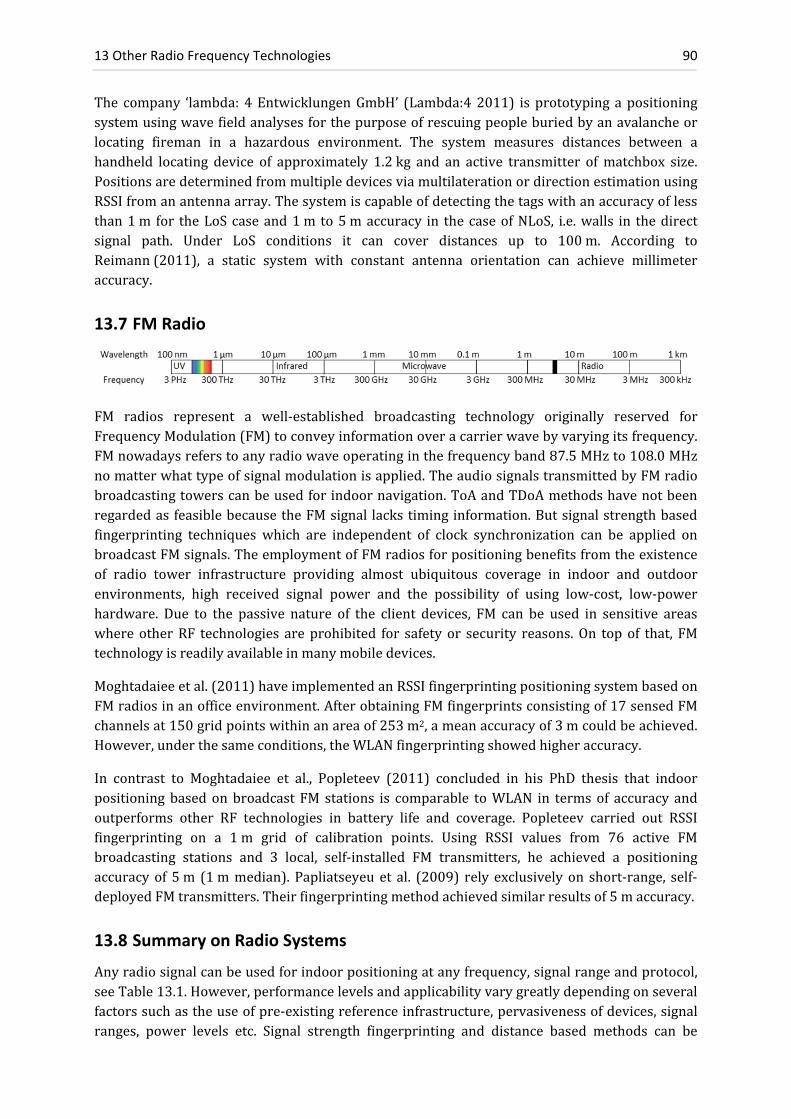
13 Other Radio Frequency Technologies 90
The company ‘lambda: 4EntwicklungenGmbH’ (Lambda:42011) isprototypingapositioningsystemusingwavefieldanalysesforthepurposeofrescuingpeopleburiedbyanavalancheorlocating fireman in a hazardous environment. The system measures distances between ahandheld locating device of approximately 1.2kg and an active transmitter ofmatchbox size.PositionsaredeterminedfrommultipledevicesviamultilaterationordirectionestimationusingRSSIfromanantennaarray.Thesystemiscapableofdetectingthetagswithanaccuracyoflessthan1m for theLoScaseand1m to5maccuracy in thecaseofNLoS, i.e.walls in thedirectsignal path. Under LoS conditions it can cover distances up to 100m. According toReimann(2011), a static system with constant antenna orientation can achieve millimeteraccuracy.
13.7 FM Radio
FM radios represent a well‐established broadcasting technology originally reserved forFrequencyModulation(FM)toconveyinformationoveracarrierwavebyvaryingitsfrequency.FMnowadaysreferstoanyradiowaveoperatinginthefrequencyband87.5MHzto108.0MHznomatterwhattypeofsignalmodulationisapplied.TheaudiosignalstransmittedbyFMradiobroadcastingtowerscanbeusedforindoornavigation.ToAandTDoAmethodshavenotbeenregardedas feasiblebecausetheFMsignal lackstiminginformation.Butsignalstrengthbasedfingerprinting techniques which are independent of clock synchronization can be applied onbroadcastFMsignals.TheemploymentofFMradiosforpositioningbenefitsfromtheexistenceof radio tower infrastructure providing almost ubiquitous coverage in indoor and outdoorenvironments, high received signal power and the possibility of using low‐cost, low‐powerhardware. Due to the passive nature of the client devices, FM can be used in sensitive areaswhereotherRF technologies areprohibited for safety or security reasons.On topof that, FMtechnologyisreadilyavailableinmanymobiledevices.
Moghtadaieeetal.(2011)haveimplementedanRSSIfingerprintingpositioningsystembasedonFMradiosinanofficeenvironment.AfterobtainingFMfingerprintsconsistingof17sensedFMchannelsat150gridpointswithinanareaof253m2,ameanaccuracyof3mcouldbeachieved.However,underthesameconditions,theWLANfingerprintingshowedhigheraccuracy.
In contrast to Moghtadaiee et al., Popleteev (2011) concluded in his PhD thesis that indoorpositioning basedonbroadcast FM stations is comparable toWLAN in termsof accuracy andoutperforms other RF technologies in battery life and coverage. Popleteev carried out RSSIfingerprinting on a 1m grid of calibration points. Using RSSI values from 76 active FMbroadcasting stations and 3 local, self‐installed FM transmitters, he achieved a positioningaccuracyof 5m (1mmedian).Papliatseyeu et al. (2009) rely exclusively on short‐range, self‐deployedFMtransmitters.Theirfingerprintingmethodachievedsimilarresultsof5maccuracy.
13.8 Summary on Radio Systems
Anyradiosignalcanbeusedforindoorpositioningatanyfrequency,signalrangeandprotocol,seeTable13.1.However,performancelevelsandapplicabilityvarygreatlydependingonseveralfactorssuchastheuseofpre‐existingreferenceinfrastructure,pervasivenessofdevices,signalranges, power levels etc. Signal strength fingerprinting and distance based methods can be

13.8 Summary on Radio Systems 91
considered.While fingerprinting atmeter level accuracy is impracticable due to the requiredpre‐calibration, time‐of‐flight measurements remain unreliable indoors due to complicatedsignalpropagation.Theoutstandingsub‐millimeteraccuracywhichinterferometryoffersisonlyofrelativetypeandthereforehardlyapplicableforindoornavigation.
Table13.1LocalizationsystemsusingvariousRFtechnologiesandreportedperformanceparameters
Name Year Wireless
Technology
Reported
Accuracy
(m)
Area (m2) or
No. of Refer‐
ence Nodes
Principle Prior
calibra‐
tion
Application Market
Maturity
Larrañaga 2010 ZigBee 3 m 432 / 8 = 54 RSSI distance minimal context, LBS study
Tadakamadla 2006 ZigBee 3 m 192 / 5 = 48 RSSI distance yes WSN, tracking study
My‐Bodyguard 2011 Zigbee room 1 per room CoO no tracking product
Aalto 2004 Bluetooth 20 m 2E4/9= 2222 CoO no advertising study
Bargh 2008 Bluetooth room sub room fingerprinting yes LBS study
ZONITH 2011 Bluetooth room 1 per room CoO no employee tracking product
Kranz 2010 DECT phone 5 m 900 / 12 = 75 fingerprinting yes seamless positioning study
Schwaighofer 2003 DECT Phone 7.5 m 4E4 /15 =3E3 fingerprinting yes LBS study
Rabinowitz 2005 Digital TV 10‐20 m 15 km2 pseudoranges no emergency response study
Serant 2011 Digital TV 10‐25 m 80 km2 pseudoranges no urban LBS study
Varshavsky 2007 GSM 4 m building / 29 fingerprinting yes indoor localization study
Loctronix 2011 GSM 1‐15 m 325 / 2= 176 Doppler ranges no LBS on cell phones product
Shen 2010 GSM 150 m 12km2/tower ECoO, RTT no mobile phone LBS simulation
Stelzer 2004 FMCW radar 10 cm 500 x 500 m2 multilateration no race track study
Symeo 2011 FMCW radar 5 cm 4E4/3=1.3E3 RTT, beacons no forklift tracking product
ABATEC 2011 FMCW radar 3 cm 1 km2 multilateration no sport analysis product
Nanotron 2011 CSS 1 m 2‐16 beacons ToA, beacons no loss protection product
Solcon 2011 CSS meter > 2 per room TWR, beacons no facility management product
Yokoo 2009 radar 0.3 % 25 m2 Doppler radar no first‐responders study
Lambda:4 2011 radar 1 m 1 or more lateration, RSSI no avalanche rescue product
Moghtadaiee 2011 FM Radio 3 m radio stations fingerprinting yes indoor navigation study
Popleteev 2011 FM Radio 5 m radio stations fingerprinting yes employee tracking study
Papliatseyeu 2009 FM Radio 4.5 m 72 / 3 = 24 fingerprinting yes employee tracking study

14 Inertial Navigation Systems 92
14 Inertial Navigation Systems
This chapter outlines Pedestrian Dead Reckoning (PDR) approaches based on InertialNavigation Systems (INS) consisting of an InertialMeasurement Unit (IMU) and a processingunit as the main components. Since an INS has a significant drift, it is usually fused withcomplementarysensorswhichprovideabsolutelocationinformation.
An INS is an electronic device which provides estimates of position, velocity and orientationfromanIMU.ThecustomIMUconsistsofthreeorthogonallyarrangedaccelerometers(motionsensors), three gyroscopes (angular rate sensors) and/or a magnetometer (3 perpendicularsensors formeasuringthestrengthand/ordirectionofamagnetic field). If the initialpositionand orientation are known, subsequent positions, orientations and velocities (direction andspeedofmovement)of themovingplatformcanbeupdatedcontinuouslyviaDeadReckoning(DR) without the need for external reference positions. The main argument to use INS forpedestrian navigation arises from independent operability – at least temporarily – withoutexternalinfrastructure,makingnavigationpossibleinenvironments,wheretheinstallationandmaintenance of such infrastructure is not affordable. Comprehensive information about themodesofoperationandapplicationsofanINSisgivenbyJekeli(2001).
14.1 INS Navigation without External Infrastructure
Using DR, an INS‐based guidance system is continually adding detected changes to itspreviously‐calculatedpositions.SinceDRisonlysensitivetochanges,theINScanonlymeasurerelativepositionandorientation.Thus,theaccuracyofthepropagatedpositiondependsheavilyon thequalityof theprovidedstartpositionanddirection.Mostnotably,owing to thedoubleintegration of noisy accelerometer measurements, INS suffer from accumulation of positiondeviationandmagnificationof theangulardeviationover the travelleddistance (Abbeerror).The shorter the integration time the higher is the predicted position from an INS. If absolutepositionororientationupdatesareobtainedbyanothersensorsourceatahighrate,theINScanbeused todeliverpositionswithmuchhigherprecision compared to geometric interpolationbetweensupportingpoints.
Inpedestriannavigation,theaccumulatingpositioningdeviationofDRoriginsfromtwomajortypesofdeviations:thealong‐trackdeviationmainlycausedbythesteplengthimprecisionandthecross‐trackdeviationmainlycausedbytheimprecisionoftheazimuthmeasurement.Whilethe accuracy deteriorates over a long operation time by variance accumulation, the INS canprovide – as mentioned above – very high short term accuracy and detailed shapes of thetravelledroute.ThereforedeadreckoningbasedonINSisoptimallyutilizedforprovidingshort‐

14.2 Pedestrian Dead Reckoning 93
termsolutionsinshadowortransitionareaswhicharenotcoveredbyanabsolutepositioningsystem.
Nowadays the utilization of Micro Electro‐Mechanical System (MEMS) sensors allowsintegrating all system components in a mobile smart phone (Lukianto et al. 2010). Theminiaturization is keeping costs, power,weight and required space to aminimum. ThereforeMEMSbasedINSsensorsareparticularlyefficientforthepurposeofpedestriannavigation.Notethat 3500€ are considered ‘low‐cost’ compared to high precision INS at a cost of up to150’000€. Since an INS operates self‐contained the availability and continuity of service areusually guaranteed. Most critical for the applicability of an INS are the performance metricsaccuracy and integrity. Accuracy of pedestrian navigation systems is usually indicated in theratiobetweendeviationandcovereddistanceor elapsed time.The ratioexpressed inpercentdeviationof travelleddistancevariesgreatlybetween0.1%and20%dependingon theusedmethodology and employment of complementary sensors. In Table 14.1 various INS‐basednavigationapproachesandtheircomponentsarecharacterized.
Mathiassen et al. (2010) built a low‐cost test IMU supported with observations frommagnetometersandabarometer.Magnetometersandbarometersarenotofhighaccuracyandreliability, but provide absolute quantities which can support a self‐contained IMU. Whilesimulatedvariancepropagationpredicts10mdriftdeviationwithin60s, firstreal‐worldtestsyielded65mdeviationwithinthesametimeintervalbasedonastationaryunit.Beforesuchalow‐costsystembecomesapplicable,thegyroscopedrift–asthemainerrorsource–needstobeimproved.
14.2 Pedestrian Dead Reckoning
Fromcontinuousupdatesofthewalkeddistanceandheading,thepositioncanbepropagatedbyDeadReckoning(DR).Thefundamentalmechanismofpedestriandeadreckoningreads
sincos
, (14.1)
where l is the step length, θ the current heading estimate and (x,y) the coordinates in thehorizontalplane.Indexkisanabbreviatedformoft(k)denotingthenumberofadiscretepointintime.
14.2.1 Step Length Estimation
Apedestrian’saccelerometeroutputcanbeusedforstepdetection,stepcountandsteplengthestimation.For thispurpose it isnecessaryto firstcategorize thehumanphysicalactivity intowalking, running, ascending/descending stairs, taking an elevator, standing still and irregularmovements. Different dynamics in the movements can be recognized from accelerometersintegratedinamobiledevicewhichiscarriedonthewaistorheldinthehand.Whereandhowthedevice (i.e. the IMU) iscarriedby theperson isdecisive for theprocessingandaffects theperformance. Foot mounted devices allow applying additional constraints (such as zerovelocities while walking) and special algorithms. Therefore, foot mounted approaches arediscussedseparatelyinSection14.4.
Sun et al. (2009)make use of thewaveforms of all three acceleration components to classifyrelevantpedestrianactivities.Fromtheaccelerationsignal,deducedquantitiessuchasvelocity,distance,signalmagnitude,meanandvariancecanbederivedandanalyzedforactivitylabeling.

14 Inertial Navigation Systems 94
Baoand Intille (2004) identifieddifferentactivitieswitha success rateof ca.90%.Shinetal.(2009)demonstratedtheimportanceofbehaviorclassification(suchassit‐down,walkandrun)forIMU‐basedpedestriannavigation.Contextawarenessofapersoncanbeobtainedbyasteplengthestimatorimprovingthenavigationperformanceofasystemsignificantly.Thestepsaredetected by identification of periodicities, typically by filtering the signal magnitude of thepedestrian’sacceleration.Inordertodeterminethetravelleddistancethestepsarecountedandthesteplengthsareestimatedfromthestepfrequency.AsshowninFigure14.1,thesteplengthincreaseslinearlywiththestepfrequency.Inaddition,theaccelerationvariancecanalsogiveanindicationof the step length, seeFigure14.2.Whenanabsoluteposition is available, the steplengthcanberecalibratedduringthewalk.Suchanonlinecalibrationtechniqueadaptsverywelltoacertaincontextoranewsituation.
Figure14.1SteplengthinrelationtothestepfrequencyaccordingtoShinetal.(2009)
Figure14.2 Accelerationvarianceversussteplength,Shinetal.(2009)
14.2.2 Step Heading Estimation
The heading can be determined with azimuth readings of a leveled compass with a typicalaccuracyof5°(Gusenbaueretal.2010).Thereliabilityofcompassreadingsiscompromisedbymagneticperturbations causedbypower linesor iron reinforcementandmisalignmentof thedevice(i.e.thelineofsightofapedestriandoesnotcorrespondtothedirectionofwalk).Amorereliableandthereforemorecommonapproachfordirectionestimationistheuseofagyroscope.
14.3 INS Pedestrian Navigation Using Complementary Sensors
Since the position deviation of dead reckoning grows with the time and distance traveled,position updates from an external source are necessary from time to time. Since in indoorenvironmentsGNSSareoftenseverelydegraded,therequiredexternalpositioninginformationis typicallyobtainedbybeaconbasedsystemssuchasWLAN,UWBorultrasound. Inprincipleanyotherabsolutepositioningsystemcanservethispurpose.Thepedestriannavigationsystemcanhelptonavigatethroughareaswherethecomplementarysystemhaspoorornocoverage.
IntegrationoftheINSwithacomplementarysystemcanhavetheformofloosecouplinguptoultra‐tightcoupling.Inalooselycoupledsystemtheexternalpositioningsourceisautonomouslycalculating a navigation solution and afterwards integrated in the INS solution. Ultra‐tightcoupling combines the raw observations into a navigation filter andmakes use of a trackingfeedbackloop.
14.3 INS Pedestrian Navigation Using Complementary Sensors 95
Themainchallengeintheimplementationofhybridlocalizationalgorithmsistheformulationoftheprocess and themeasurementmodels.By applyingKalmanorParticle filters, data fromalarge number of sensors can be fused such that the drawbacks of each sensor can becompensatedwithinformationfromothersensors.
Sensorsforpedestriannavigationcanbesubdividedintothetwomainclasses:a)infrastructureindependent sensors and b) sensorswhich require deployed local infrastructure. The secondimportantcriterionforsubdivisioniswhetherthesensorcanmeasureana)absolutequantityorb) relative changes to the target quantity. E.g. an accelerometer measures the absoluteacceleration,but sincepositionororientationangles are the targetquantities, accelerometersbelongtotheclassofrelativelymeasuringsensorsinthiscontext.
IfanIMUdoesnottakeadvantageoflocalinfrastructure,theerrorgrowthresemblesaquadraticfunction with the elapsed time (Jekeli 2001). In order to increase long‐term stability, theposition estimates need to be supported by a complementary system providing absoluteposition and possibly orientation references. Sensors employed to deliver absolute positioninformation are typically GNSS (for 3D) and barometric pressure sensors for the heightcomponent.ApartfromGNSS,anyothersensortechnologydescribedinthisreportcanbeused(see Sections 14.3.2to14.3.5). The absolute orientation reference can be obtained fromcompasses(azimuthalorientation),magneticfieldsensors(allthreedimensions)orinclinationsensors(two‐axishorizontalorientation).Alternatively,theorientationcanbederivedfromthepositiontrackifabsolutepositions(suchasthoseobtainedfromGNSS)areavailable.
14.3.1 Combination of INS and GNSS
MostpedestriannavigationapproachesincludeGNSSreceiversintheirsystemarchitecture.TheadvantageofacombinedtechniqueisthatpedestriandeadreckoningandGNSSdonotrequirelocaldeploymentofinfrastructure.Therefore,thefusionofinertialnavigationandGNSSallowsfor infrastructure‐free positioning, which is a requirement formany applications, such as forrescue, fireman and soldiers. Since GNSS provides an absolute initial position and directionwhenenteringabuilding,itisacrucialcomponentforanyINS‐basedindoorapplication.GNSSisalsousedforcalibrationandvalidationofpedestriannavigationsystems,e.g.Beauregard(2006)whomountedthesensorsonahelmetorSunetal.(2009)whopreferredattachingthesystemonapedestrian’sbelt.Renaudinetal.(2007)mountedanAGNSSreceiveronapedestrian’scapand fused the GNSS observations with three inertial systems distributed over the body.However,thedeteriorationofAGNSSindoors(Chapter11.2)causesthesystemtorelysolelyonINSwhilethepedestrianwalksinabuilding.
14.3.2 Combination of INS and AoA
Kemppietal.(2010)accommodateabsolutelocationestimatesfromanangle‐basedlocalizationsystem.Theazimuthandelevationanglesofthemobilereceiveraredeterminedbydirection‐of‐departureprinciplefromamulti‐antennaarray.Abuildingmapisalsousedformapmatchingand fused thewith the IMUand anglemeasurements.Kemppi et al. report adeviationof 7mafterwalking2.5minutes(190m)andadeviationof15msubsequent toawalkof6minutes(270m)usingasingleantenna.
14.3.3 Combination of INS and Optical Measurements
Aufderheide and Krybus (2010) propose a dual‐track system combining inertial and opticalmeasurementsasa looselycoupledsystem.Thecamerapose isestimated fromcorrespondingimage features between successive frames from a monocular video camera. Therefore, their

14 Inertial Navigation Systems 96
approach is also categorized as a camera system with reference from image sequences(Chapter4.2).Theknowledgeof the cameraposition isused tobound thedrift of the inertialsystem for long track durations. Conversely, pose estimations from IMUdata limit the searchspace for feature tracking. Performance assessment is not yet possible because the system iscurrentlyunderdevelopment.
Keßler et al. (2011)use a rotating laser scanner and alternatively amonocular camera to aidtheir pedestriannavigation system.The scandata is used to generate a 2Dmapandnavigatewithin thismap.Geometricalconstraints insidebuildings(e.g.orthogonalityofstructures)areusedtorecognizeifaplaceisrevisited.FromthecameraimagesthecentralvanishingpointsaredeterminedtoreducetheheadingdriftoftheIMU.Complementarytothevision‐basedattitudeaiding method, the position can be directly determined from comparison of images in adatabase.Testswithclosedloops,whichhavebeenwalkedtwice,showconsistentpaths.
TheSLAM(SimultaneousLocalizationAndMapping)approachofLiuT.etal.(2010)combinesIMU, laserscannerand imagebased localization,all integrated inahuman‐operatedbackpacksystem which can be used to generate 3D models of complex indoor environments. Thepositions are determined from data capture based on two laser scanners and an IMUwith 6Degree of Freedom (DoF). An average positional error of 1% of the travelled distance isreported.The localizationperformancecanbe improvedbymakinguseof the camera imageswhichhavebeentakeninanofflinephase.Theimagescanbeusedtorefinethesixparametersofthecameraposeandimprovethequalityofthe3Dtexturedmodel.
14.3.4 Combination of INS and RSSI
Seitz et al. (2010) fuse low‐cost accelerometer data with WLAN RSSI fingerprintingmeasurementsusingtheHiddenMarkovModel.Theirpedestriannavigationsystemisdedicatedforlow‐cost,low‐powersensorsintegratedonsmartmobilephonesandachieves5maccuracyinindoorenvironments.Finketal.(2010)alsofusetheINSmotionvectorwithradiolocalizationusingreceivedsignalstrength.Theirpedestriannavigationsystemisdesignedforthedetectionofmaintenancestaff in longwallmining,whichisanundergroundcoalminingtechnique.WiththecombinationofWLANpathlossdistancesandINSreadingstheyreportapositionaccuracyof0.7m – in contrast to a solution on WLAN fingerprinting of 5m accuracy. With such animprovement the security zone can be reduced and the mining can be carried out moreefficiently.
Apart fromWLAN, it is alsopossible touse anetworkof ZigBeenodes at known locations toperformfingerprintingincombinationwithapedestriannavigationsystem.Schmidetal.(2010)predictthatsuchasystemhasthepotentialtoprovide3maccuracywithinbuildings.
14.3.5 Ultra Hybrid Systems
Klingbeil et al. (2010) present a modular fusion system for pedestrian navigation or roboticapplications.Thesensorplatformincludescommonself‐containedsensorswornontheperson.For reference position updates GNSS can be used but it is also possible to utilize any othertechnique as reference such as deployed ultrasound nodes or radio frequency beacons. Thesystem architecture is set up in such a way, that in principle all sensor modalities can beemployedas‘controlinput’orbroughtinasobservationsforaparticlefilter.TheprocessingisbasedonaBayesianrecursiveestimationalgorithm.

14.4 Foot Mounted Pedestrian Navigation 97
14.3.6 Combination of INS and Map Data
Therequiredabsolutepositionupdatesdonotnecessarilyneedtooriginfromexternaldeployedinfrastructure. Alternatively, detailedmap data can be used, known asmapmeasurements. Ifavailable indoor maps such as microMap or a CityGML are stored locally in the device, self‐containednavigationbecomes feasible. For correction of position andorientation, constraintsfromamapcanbecomparedwith themovementpattern tocreatecomplementarygeometricinformation.ThisprocessisknownunderthetermMapMatching(MM)andusedtocorrectthecurrent position track onto a map. The map matching approach exhibits a powerful backupstrategy for correcting the position of the Dead Reckoning (DR) system. While car‐roadmapmatching is alreadyanestablished tool inoutdoornavigation, the less constrainedmovementpatternofapersonrequiresspecialmapmatchingalgorithmstailoredtopedestriannavigation.
VerticaldisplacementsofpedestriansinbuildingshavebeenusedbyGusenbaueretal.(2010)toidentifyanelevatororascending/descendingstairs.Wagneretal.(2010)useatopologicalMapMatching(MM)algorithmto feedbackaKalmanFilterwhenGNSSpositionsarenotavailable.Walder and Bernoulli (2010) propose the use of a building informationmodel for theirmapmatching approach. Themodelprovides two important constraints to apedestrian’s track: a)thepolygonsoftheoutlineofaccessibleareasandb)transitionobjectssuchasdoorsorstairs.
Pressl and Wieser (2006) present a pedestrian navigation system tailored to the needs ofvisuallyimpairedpeopleinanurbanenvironment.ByintegratingIMU,GNSSandmapmatchingthesystemachievesanabsoluteaccuracyof1mto2m.
14.4 Foot Mounted Pedestrian Navigation
TheinstallationofanIMUinashoehasthepurposetomitigatetheinertialdrift.Footmountedpedestrian navigation systems benefit considerably from supporting the IMU integrationprocesswithaZerovelocity‐UPdaTe(ZUPT)oraZero‐AngularRateUpdate(ZARU).Duringthefoot is in stance stage the velocity estimation is recalibrated from the integrated accelerationwithazerovalue.TheseupdatescanbeusedasobservationinputtotheKalmanfilterinordertoefficientlyreducetheerroraccumulationofanIMU.ThedifficultyoftheZUPTapproachisthedetection of themoment of zero velocity under changing conditions such as various types ofmotionandspeedsordifferentfloorcover.
The ZUPT method allows replacing cubic in time error growth (t3‐drift) with an erroraccumulationlineartothenumberofsteps(WanandFoxlin2010).Figure14.3illustrateshowvelocityupdatescircumventacubicerrorgrowth.Thezerovelocityupdatescanbeintroducedinto theEKF (ExtendedKalmanFilter)asvelocitymeasurements,with thepurpose todeduceandcorrectthedriftdeviation(Figure14.3b).Thecomparisonofcurrentpedestriannavigationsystems in Table 14.1 shows that a drift of less than 1% can be achieved by foot mountedsystems,comparedtoIMUsattachedtootherbodypartswithdriftstypicallyexceeding1%ofthe travelled distance. Despite superior performance compared to hand‐held devices, shoemountedIMUsareconsideredas lesspractical forconsumers,becausesuchsystemsrequireaspecialarrangementtointegrateanIMUintoashoe.
Nilsson et al. (2010) have developed a methodology for performance assessment of foot‐mounted and ZUPT assisted IMUs. As a result from variance propagation, the achievableperformance for such a system is in the range of 0.1% to 0.44%, depending on externalinfluences.

14 Inertial Navigation Systems 98
Skogetal.(2010)studiedtheperformanceofdifferentzero‐velocitydetectorsforfootmountedinertial navigation. Four different strategies of zero‐velocity updates have been investigated,namely the acceleration moving variance detector, the acceleration magnitude detector, theangularrateenergydetector,andanewdevelopment,referredtoasSHOEdetector.Thelasttwozero‐velocityupdatesshowed thehighestpositionaccuracywith0.14%deviationof the totaltravelleddistance.
InterSense Inc. is currently prototyping a foot mounted inertial navigation system namedNavShoeTMforthepurposeofguidingfirstrespondersinhazardousenvironments.Thepositiondata from a dead reckoning module can be fused with GNSS or alternatively with RFobservations. The unassisted system of Wan and Foxlin (2010) reached a drift deviation of0.27%ofthetravelleddistance.
14.4.1 Combination of Foot Mounted INS and Maps
Aswith the general application for navigational IMUs in combinationwithmaps (see 14.3.6),footmounted inertialdatacanbe fusedwithmapmatching.ApedestrianguidancesystemforassistingrescueteamshasbeensuggestedbyWalderandBernoulli(2010).TheapproachusesZUPTwheretheconstraintsfromasemanticBuildingInformationModel(BIM)areassumedtobeavailable.ThepositioningaccuracydependsonthepropertiesoftheBIMandthequalityofthemap‐matchingalgorithm.
14.4.2 Combination of Foot Mounted INS and Signal Strength
ThefootmountedsystemproposedbyJiménezetal.(2010)reliesonReceivedSignalStrength(RSS)fromactiveRFIDtagsplacedatknowncoordinatesinabuilding.Atanemissionfrequencyof1Hz,thebatterylifetimeisexpectedtosupporttheINSbasedpedestriannavigationsystemfor 6months. In order to take advantage of ZUPT, the INS sensor is attached to the foot. Inaddition,ZeroAngularRateUpdates(ZARU)duringstancestagesofthewalkareused.Fromtheself‐containedinformationaloneadeviationof1%ofthetravelleddistanceisreported.AswithRSSIfromRFID,signalstrengthfromWLANcanbecombinedwithfootmountedINS.Franketal.(2009) reduced the mean position deviation from 3.2m to 1.6m by fusion of WLANfingerprintingandshoedata.
14.4.3 INS Mounted on Both Feet
PlacingIMUsonbothfeetprovidestheZUPTapproachwithfurtherreliability,redundancyandcontinuityofservice.MountingaMEMSinertialunit toeach footofapedestrianprovidestwoindependentnavigationsolutions.Duringthehumangaitcycletheseparatingdistancesbetweenthese two position solutions can be used as constraints. Bancroft et al. (2008) integrated theinertialdataoftwoIMUsintoasingleKalmanfilterandcomparedthesingleIMUapproachand
Figure14.3DriftoffootmountedIMUsaccordingto(WanandFoxlin2010),usinga)ZUPT,b)EKFzero‐
velocitypseudomeasurements

14.5 Summary on INS Based Systems 99
the twin approach with each other. Test runs showed that the position accuracy could beimprovedbymorethan60%.
14.5 Summary on INS Based Systems
TheperformanceofINSbasedpedestriannavigationdependsonseveralfactors:thefrequencyofabsolutepositioningupdatesprovidedbyacomplimentarysensorsystem,thequalityoftheIMUusedandtheamountofadditionalinformationderivedfromthehuman’sgaitcycle.Foot‐mounted systems can make use of zero velocity during the foot is in stance stage and havethereforeadriftoflessthan1%ofthetravelleddistancecomparedtoIMUsmountedatotherbodypartswithdriftsbeingtypicallylargerthan1%.INSbasednavigationistheonlyapproachwhichcanbeusedwithoutanyinfrastructure–atleastforacertaintimespan.AcomparisonofINSbasedapproachesincludedinthissurveyisgiveninTable14.1.
Table14.1Pedestriannavigationapproaches,sensorsusedandperformanceparametersasreported
Name Mounting
Body Part
or Device
Accuracy
(% of Distance
Travelled)
Accelero
meters
Gyro
scopes
Baro
meter
Magn
etometer
GNSS
Map
Info.
RSSI
ZUPT
ZARU
Local Reference IMU Sensors EKF Maturity
Lukianto phone ‐ 3 3 y y y ‐ ‐ ‐ ‐ WLAN,Bluetooth MTI‐G Xsens y suggest.
Mathiassen unspecified 23 %, 10 m / 60 s 3 3 y 3 y ‐ ‐ ‐ GNSS, Barom. ADIS16405 y study
Sun belt 2% 3 3 ‐ y y ‐ ‐ ‐ ‐ GNSS AK8976A y study
Beauregard helmet few % 3 3 ‐ 3 y ‐ ‐ ‐ ‐ GNSS MT9 Xsens ‐ study
Bao limbs activity detection 9 ‐ ‐ ‐ ‐ ‐ ‐ ‐ ‐ ‐ ADXL201 ‐ study
Shin phone 1% ‐ 5% 3 3 ‐ 3 ‐ ‐ ‐ ‐ ‐ ‐ MEMS ‐ study
Kemppi waist/pocket 16%, 17 m 3 3 ‐ ‐ ‐ ‐ ‐ ‐ ‐ map, beacon Accelerometer PF study
Aufderheide camera ‐ 3 3 ‐ 3 ‐ ‐ ‐ ‐ ‐ images MEMS y suggest.
Keßler chest / foot ‐ 3 3 y y ‐ y ‐ y ‐ images SCA / ADIS16255 y study
Liu T. backpack 1 % 3 3 ‐ 3 ‐ ‐ ‐ ‐ ‐ scanners, Images InertiaCube3 ‐ study
Seitz phone 5 m 3 ‐ ‐ 3 y ‐ y ‐ ‐ WLAN RSSI Bosch BMA150 ‐ study
Fink belt 0.67 m 2 1 ‐ ‐ ‐ ‐ ‐ y ‐ RSSI LIS3LV y study
Schmid body 5 %, 3 m 3 3 ‐ ‐ ‐ ‐ y ‐ ‐ ZigBee RSSI MTI‐G Xsens y study
Klingbeil waist 1 m – 6 m 3 3 y 3 y y ‐ ‐ ‐ GPS, US,RF, CSS Accelrometer y prod
Gusenbauer phone 4% 3 ‐ ‐ y y y ‐ ‐ ‐ map, A‐GNSS N97 y study
Wagner phone/car 1 – 15 m y y ‐ ‐ y y ‐ ‐ ‐ map built in CAR y test
Pressl Belt 1 – 2 m 3 1 y 3 y y ‐ ‐ ‐ map, GNSS PNM Vectronix y prototype
Nilsson foot 0.1% – 0.44% 3 3 ‐ ‐ ‐ ‐ ‐ y ‐ ‐ ‐ KF simulation
Skog foot 0.14 – 0.20% 3 3 ‐ ‐ ‐ ‐ ‐ y y ‐ MicroStrain3DM y study
Wan NavShoe foot 0.14 % 3 3 ‐ ‐ ‐ ‐ ‐ y ‐ test without NavChip y prototype
Walder foot ≈building model 3 3 y y y ‐ y ‐ map matching MTI‐G Xsens y study
Jiménez foot 1% ‐ 1 m 3 ‐ 3 ‐ ‐ y y y RFID RSSI MTI‐G Xsens y study
Frank foot 1.6 m 3 3 ‐ y ‐ ‐ y y ‐ WLAN RSSI MEMS y study

15 Magnetic Localization 100
15 Magnetic Localization
Positioning systems using artificial magnetic and electromagnetic fields are described in thischapter. Magnetic fields can be generated from permanent magnets or from coils usingAlternatingCurrent(AC)orpulsedDirectCurrent(DC)fields.Electromagneticfieldscanalsobeusedforpositioningincombineduseoftheirelectricfieldandmagneticfield.Thetwosourcesofelectromagnetic fields are static charges producing electric fields and currents producingmagneticfields.Oscillatingchargesproduceelectricandmagneticfields.
15.1 Systems Using the Antenna Near Field
TheNear‐FieldElectromagneticRanging(NFER)usesthepropertiesofradiowaves,wherethenear field encompasses an antenna or, more generally, any electromagnetic radiation sourcewithanapproximatesphereofradius1/6oftheradiationwavelength(Capps2001). InNFER,thedistance fromasmall transmitterantenna isderived fromthephaserelationbetween theelectricandthemagneticfieldcomponentsofanelectro‐magneticfield.Thereceiverunitmustbeabletoreceivethetwosignalcomponentsseparatelyandcomparetheirphases.Closetotheantenna,thesecomponentshaveamaximalphasedifferenceof90°.Sincethephasedifferencedecreases with the distance to the antenna it can be used for range determination within acertainproximitytotheantenna.AsamajoradvantageNFERdoesnotrequiresynchronizationorsignalmodulation.Secondly,if lowfrequenciesaround1MHzareused,thesignalshavethepotentialtopenetratewalls.Ontheotherhand,theuseoflowRFfrequenciesrequireslargere‐ceiverunitssinceanefficientreceiverantennaneedstobewithinaquarter‐wavelengthinsize.
The2DlocationsystemQ‐Track,characterizedinSchantzetal.(2011)makesuseoftheNFERprinciple. The system is designed for an operating range of λ∙(2π)‐1 where the appliedwavelength isλ=300m(1MHz).Measurementsare taken inanofficeenvironmentwithnon‐line‐of‐sightconditions(i.e.throughthewalls).Thereportedaveragedistancedeviationis55cmwithanoperatingrangebetween1.4mand23m.Anaccuracyof1misreportedfor83%ofthex‐andy‐positionswhicharedeterminedfrommultilaterationusing5fixedreceivers.
15.2 Systems Using Magnetic Fields from Currents
Magneticfieldsareproducedbymagneticmaterialorelectricalcurrents.Atypeofpositioningsystemmakesexclusiveuseofthestrengthandthedirectionofthemagneticfield.Tworelated,

15.2 Systems Using Magnetic Fields from Currents 101
butseparatelytreatedmeasuresexistforthemagneticfield:themagneticfieldstrengthH(A/m)andthemagneticfluxdensityB(Tesla).Therelationofthetwoquantitiesis
μ , (15.1)
whereµistheamaterialdependentparameterknownaspermeability.Thepermeabilityvariesnotonlywiththeconductivityofthematerialbutalsowiththetemperatureandthefrequencyof the field. Despite the variability of µ, providers of magnetic positioning systems use thesimplifiedterm‘magneticfield’consideringHandBtobeproportional.
Direct Current (DC)magnetics use pulseddirect currentswhere the current frequency is lowenough to be considered static. Static magnetic fields are caused by different direct currentsources,suchascoilsorwires.
15.2.1 Systems Using Coils
Anartificialquasistaticmagneticfieldcanbecreatedbyelectricalcoils.Ausefulpropertyofacoilbasedmagneticfieldisthatitcanbewellpredictedfromatheoreticmodel.Thefluxdensityofaverticallyorientatedcoilis
,μ4
1 3sin , (15.2)
whereµ0ispermeabilityofvacuum,uthenumberofloops,I theelectriccurrent,Ftheareaofthecoil,ϕtheelevationangleofapointPinrelationtothecoilandrthedistanceofthatpointtothecoil.Duetorotationalsymmetryofacoil,thefluxdensityBisindependentofthehorizontalangle. At a mobile magnetic field sensor,B can bemeasured at any pointP within the field.Equation(15.2)canberesolvedfordistancerandelevationangleϕ. Ifmultiplecoilsgeneratemagneticfieldsatknownlocations,therelative3Dpositionofthesensorcanbedetermined.Thecoil‐based approach has several advantages: a) it can be used under NLoS conditions, b) themagneticfieldisnotaffectedbyreflectionormultipathandc)kinematictrackingispossibleathighmeasurementrateswithanunlimitednumberofsensors.
BlankenbachandNorrdine(2010)havebuiltanexperimentalmodelusingacoilwith0.5mindiameter and 140 loops. A ranging accuracy of a few centimeters was achieved for shortdistancesof lessthan10m.For largerdistances, themagnetic fieldturnedouttobetooweakand thereforevulnerable tonoise.Oneof the resultswas that there is adiscrepancybetweentheoreticalmodelandobservation,whichindicatesarequirementforpriorsystemcalibration.
Ascension(2011)provides thecoilbasedsystem ‘trackSTAR’whichusespulsedDCmagneticfield transmitterswithoperating rangesbetween0.8mand4.2m.For theversionwith largeareacoverageof4m,thepositioningaccuracyofstaticobjectsisstatedas3.8mm.
Arumuametal.(2011)haveusedanemitterdrivenat387kHzconsistingof45turnsofacopperwiretogenerateamagentoquasistaticfield.Theoreticalresultsderivedfrominfinitesimaldipoleapproximationarecomparedwithexperimentalresults,indicatingthatdistancesupto50mcanbeestimatedwithanaccuracyof20cm.
15.2.2 Systems Using AC Magnetics
Unlike systems based on coils using pulsed DC technology, AC (Alternating Current) basedmagnetic trackingsystemsare lessaffectedby theEarth’smagnetic fieldandartificialmagnetfieldsfromelectricdevices.

15 Magnetic Localization 102
The electromagnetic tracker system LIBERTY from Polhemus (2011) uses ACmagnetic fieldsandupto16sensorstoobservepositionandorientationofanobjectatupdateratesof240Hz.Accordingtothereportedsub‐millimeteraccuracy,medicalapplicationsarepossiblewithinanoperatingrangeof1.5mwhichcanbeextendedupto4.6m.
InfraSurvey (2011) is offering the underground positioning system UGPS based on lowfrequencyACmagnetic fields. It has been designed formeasuring position and orientation ofobjects in underground environments such asmines, tunnels, caves or pipes, but can also beusedforindoorpositioning.Basedondistancemeasurementsbetweenstaticreceiversdeployedatthesurface, it ispossibleto locateanactivemagnetictransmitterweighing8kgwithin1mprecisionatadistanceof100mandamaximumoperatingdistanceof200m.Thepositionoftheabove‐surfacereceiverstationsaredeterminedbyGNSS.TheprincipleofUGPSisillustratedinFigure15.1.
Figure15.1Principleof‘UndergroundGPS’,InfraSurvey(2011)
15.3 Systems Using Permanent Magnets
Thesecondmethodofusingthemagneticfluxdensityforpositioningisthroughmagneticfieldscreated by permanentmagnets. A typical system consists ofmultiple staticmagnetic sensorswhich measure the magnetic flux density of a mobile magnet. Alternatively, multiple staticpermanentmagnets at known locations can be used to locate amobilemagnetic field sensor.Currentapproachesindicateameasurementvolumeof1m3,whichrestrictsthemethodtocloserange usage, such asmedical applications. Amajor challenge in positioning using permanentmagnetsarisesfromthecomplexityofthemagneticfield.Mathematicmodelsinvolvehighordernonlinearequationswhichcreateamultimodalobjectivefunctionwithmultiplelocaloptimaforthepositionsolution.
Song et al. (2009) locate a cylindrical permanentmagnet from64deployedmagnetic sensorswithinaspaceof0.5m2.Atameasurementrateof67Hzandalatencyof15ms,theyachieveanaverage position deviation of 1.8mm and an angular deviation of 1.5° in the magnet’sorientation.Thesystemaddressestheapplicationof3Dpositioningofacapsuleendoscopeinahumanbody.

15.4 Summary on Magnetic Localization 103
LiuW.etal.(2010)combineopticaltrackingandmagneticlocalizationinordertoovercometheocclusionproblemthatopticalsystemsface.Apermanentmagnetistrackedbyadensearrayofsensorswhichmeasure themagnetic flux intensity in threedimensionswithinacubic shapedmagnetic field. The advantage of using a magnetic system component is that line of sightbetweenthemagneticsensorandthetrackedobjectisnotarequirement.Theopticalmoduleisaredundantsystemcomponentwhichconsistsof4videocamerasand isusedtoenhancetherobustness todisturbanceby ferromagnetic objectswithin theworking volume. The reportedpositionalaccuracyforthecombinedsystemis1mmwithinavolumeof1m3.
15.4 Systems Using Magnetic Fingerprinting
Theideaofmagneticfingerprintingarisesfromanimalsthatdeterminetheirpositionfromlocalanomalies of the Earth’s magnetic field. Likewise in buildings, each location has its uniquesignatureof itsmagnetic fluxdensity.These fluctuations inspacearise fromnaturalandman‐made sources, such asmetal buildingmaterial, electric power systems and industrial devices.The anomalies of the magnetic field have sufficient variability in space to be detected by amagnetometer.Undertheassumptionthatthemagneticfieldinsideabuildingisapproximatelystatic,afingerprintingmethodcanbeapplied.Amagneticmapoftheroomsistakeninasetupphase, and the current location is determinedby comparing the current fluxdensitywith thefluxdensityvaluesstoredinthedatabase.
Haverinen and Kemppainen (2009) have mounted a 3‐axis magnetometer on a robot todetermineitslocationwithinabuildingbymagneticfingerprinting.Themagnetometerhasbeenmountedat theendofarodwitha lengthof0.4mtoavoidinfluenceoftheambientmagneticfield from the robot’s motor. Subsequent to a calibration phase, the detection of the robot’slocationalongapathlengthof278mwaspossible.Therobotneededtotravel25monaveragein order to get localized by comparing the magnetic flux values. Along that one‐dimensionalpath,thereportedaccuracywas0.2m.
15.5 Summary on Magnetic Localization
Unlikeothertechnologies,magnetic localizationdoesnotrequirethemaintenanceofa line‐of‐sightbetweensensorandsource.Therefore, theuseof electricandmagneticvelocity fields isadvantageousifwallsneedtobepenetratedandistheonlywaytodetectstructuresburieddeepunderground. Different approaches range from systems dedicated for surgery with less than1m3volumeoperatingatmm‐accuracy levelupto largecoverage, lowaccuracyfingerprintingsystems,seeTable15.1foracomparison.
Table15.1.Approachesbasedonmagneticlocalizationtechniquesandreportedperformanceparameters
Name Year Principle Coverage Area
Application Reported Accuracy
Market Maturity
Q‐Track 2011 near field 23 m NLoS office & industry 50 cm experimental system
Blankenbach 2010 DC field, coils 10 m NLoS indoor few cm experimental system
Ascension 2011 DC field, coils 4.2 m medical instr. guidance 1‐4 mm commercial system
Arumugam 2011 DC field, coils 50 m American football 20 cm experimental system
InfraSurvey 2011 AC magnetic field 200 m caves, mines, tunnels 1 m commercial system
Polhemus 2011 AC magnetic field 1.5 m (5 m) head & body tracking 0.7 mm commercial system
Song 2009 permanent magnet 0.5 m endoscope 2 mm experimental system
Liu 2010 permanent magnet 1 m assisted surgery 1 mm experimental system
Haverinen 2009 fingerprinting 280 m (1D) robot localization 20 cm experimental system

16 Infrastructure Systems 104
16 Infrastructure Systems
This chapter outlines indoor positioning approaches which cannot be matched to any of thetechnologies discussed in the previous chapters. These technologies make use of existingbuilding infrastructure or embed additional infrastructure into the building material. Thedevelopedsystemscanbehiddenfromitsusersintothestructuresofthebuilding.
16.1 Power Lines
PowerLinePositioning(PLP)isafingerprinting‐basedmethodtoprovidesub‐roompositioningin a household based on the existing electrical grid. In comparison to RFID systems whichrequire dense deployment of RFID chips, PLP simply uses the power line infrastructure in abuilding.TheprincipleofPLPisthatunmodulatedcarrierwavesignalsinthefrequencyrangebetweena fewkHzto20MHzaregeneratedbyaninterfacemodulepluggedintoanelectricaloutletinahome.Thesesignalsconsistofenergyrichelectricaltransientsandcanbewirelesslyreceived by passive tags. At the tag’s resonance frequency, the resonator inductively couplesbackasignalintothepowerline.Thissignalcanbedetectedinaso‐calledpowerlineinterfaceas a decaying swinging. If multiple tags with differing resonance frequencies are used, anindividualidentificationofthetagsbecomespossible.
Patel et al. (2009) present a proof of concept of their power line location system based onbattery‐lesstags.Forthecurrentsystemthereaddistancealongthepowerlineis3mto4mandthemaximalreadingdistancebetweenthetagsandtheelectricalwiringis50cm.Atthisstage,thesystemonlyprovidesthedetectionof thetagsratherthananactual locationwhichcanbeassociatedwithapositioningaccuracy.DespitetheselimitationsPateletal.seeapplicationsasfinding lost items and the detection of the absence of a tagged item. Stuntebeck et al. (2008)haveemployedwidebandsignalswithfrequenciesbetween447kHzand20MHzandtaken66fingerprintsina0.9mby0.9mgrid.Theirresultsshowthatitispossibletoachievegrid‐levelaccuracy. A drawback of the system is its low temporal stability and the degradation of thesystem in environments with disturbing electrical equipment. As a fingerprinting‐basedtechnology, there is also the requirement of an initial site survey which includes signalamplitudemeasurementsatseveralfingerprintslocations.
16.2 Floor Tiles
Passive,unobtrusiveindoortrackingofhumanbeingscanbeachievedusingmultiplefloortiles.Themainadvantage is thattheyare invisibleto theuserandthattheusersdonotneedtobeequippedwithanytags.Suchsystemscandetectastandinghumanin2Duptoanaccuracyof1

16.3 Leaky Feeder Cables 105
dm,allowingforapplicationsinhealthcareandAAL.Therearedifferentsensortechniquesthatbuildontheconceptofsmartcarpets.
ThetiletracksystemofValtonenetal.(2009)isbasedonmeasuringthecapacitancebetweenmultiple floortiles.Whenapersonisstandingoveratile, thecapacitancebetweenthehumanfeetandatransmitterincreases.Thesystemcantrackmultiplepersons,iftheystayatleastonetileapartfromeachother.Valtonenetal.reportanaccuracyof15cmforastandinghumanand41cmforawalkingperson.Alarge‐areacapacitivesystemdesignedforAmbientAssistedLiving(AAL) has been described in Steinhage et al. (2007) and commercialized under the nameSensFloor (2011). The individual mats of the textile underlay system SensFloor deliver theacquireddatatoacentralunitviaaradiolink.Rimminenetal.(2009and2010)presentafloorsensorsystem,whichusestheelectricalnear‐fieldforfall‐detection.
Anotherwayofbuildingatile trackingsystemis tomeasurethepressureunderhumans’ feet.Arrays of force‐sensitive resistors can detect the pressure on tiles deployed on the floor.Richadsonetal.(2004)describethepressure‐basedfloortracksystem‘Z‐Tiles’thatdeterminesthepositionthroughaseriesofhexagonaltiles,whichjointogethertoformaflexiblepressuresensingsurface.Inordertoforwardthepressureinformation,aself‐organizednetworkissetup.Richardsonetal.reportaresolutionof4cmandaresponsetimeofafewmillisecondsfortheirsystemwhichhasbeenprimarilydesignedforinteractivedancefloorsandgaming.
16.3 Fluorescent Lamps
Theprincipleofopticalcommunicationcanbeusedtoemploylampsforthepurposeofindoorguidance.Itispossibletoemployfluorescentlighttubeswhichhavebecomeacommontypeoflight source in office buildings. Free‐space optical data transmission using electromagneticwavesinthevisibleorinfraredbandsisenabledbymodulationofthe‘lampcurrent’.Aswitch‐mode control device produces a variation of phase or frequency of the lamp’s AC current,creatingamodulationoftheproducedluminousfluxandgeneratingasignalwithacodebeinguniquetoeverylamp.Themodulationfrequencyischosentobegreaterthan20kHz,suchthataudible noise is avoided. As a light sensor on a mobile platform passes the modulated lightsource,itspositionisdeterminedbyreadingtheuniquecodeofthenearestlamp.
Liu et al. (2006) have demonstrated feasibility for an implementation of an indoor guidancesystemfortheblindusingfluorescentlights.Apositioningsystembasedonlightcommunicationhas been combined with an IMU based navigation system by Nishikata et al. (2011). Theapproach uses visible light signals to provide absolute position updates for a dead reckoningsystem.
16.4 Leaky Feeder Cables
A Leaky feeder consists of a long coaxial cable deployed along corridors to provide radioservices in buildings and underground environments. As its name implies, a leaky feeder isdesignatedtoletradiosignalsleakoutofthecablealongits length.Whilethistechnologywasoriginallydesignedforcommunication,existinginfrastructureofleakyfeedercablescanbeusedfor indoor positioning based on radiated RF signals. Although homogeneous radio signalcoveragethroughoutthecableiswantedforcommunication,thereisanunavoidableattenuationalong its entire length.The loss in signal strength canbe used to create aRSSI fingerprintingmapwhichshowsadistinct relationbetween locationandsignal amplitude.Thepositionof a

16 Infrastructure Systems 106
receivercanbededucedduringanonlinephaseviacomparisonof thecurrent fingerprintandthose in the database. The advantage of using RSSI of leaky feeders is the robustness toenvironmentalchanges.RadiotechnologiesusedforleakyfeedercablesareGSMandWLAN.
Weberet al. (2011)carriedoutexperimentswitha40mWLAN leaky feederdeployedon theceilingofanofficehallway.Basedon41fingerprintswithaseparationof1m,itwaspossibletodeterminethe1Dpositionwithanoverallaccuracyof4m.
Pereira et al. (2011) carried out similar studies on an existing leaky feeder cable installedthroughoutthetunnelfortheLHCaccelerometerinSwitzerland.Theleakyfeedersuppliesthewholetunnelof27kmperimeterwithGSMsignalcoverage.Fingerprintsweretakeninintervalsof 200m along the entire tunnel where the longitudinal attenuation (with factors of about4dB/km)couldberelated to the tunnel chainagewithinanaccuracyof ca.200m.This resultcouldbeimprovedbyanincreasedresolutionofthecalibrationmap.
16.5 Summary on Infrastructure Systems
Existingbuildinginfrastructureaswellasinfrastructuredeployedunobtrusivelyinthebuildinginteriorforthepurposeofindoorpositioningcanbesuccessfullyusedforprovidingpositioningserviceswithinabuilding–atvarious levelsofaccuracyandcosts. InTable16.1performanceparametersofdifferentinfrastructurebasedsystemsarequantified.
Table16.1.Infrastructurebasedsystems
Name Year Principle Existing or
Deployed
Infrastructure
Coverage Application Reported
Accuracy
Market
Maturity
Patel 2009 power lines existing 3 m ‐ 4 m finding lost items detection study
Stuntebeck 2008 power lines existing building location aware homes 1 m – 3 m study
Valtronen 2009 floor tiles deployed 2.4 × 2.0 m assistance for elderly 15 cm‐40 cm prototype
SensFloor 2011 floor tiles deployed 50 m2 assistance for elderly dm product
Rimminen 2009 floor tiles deployed 19 m2 fall detection 21 cm prototype
Richardson 2004 floor tiles deployed < 4 m2 dance floor > 4 cm prototype
Liu 2006 fluorescent lamps existing building guidance for the blind ‐ study
Nishikata 2011 fluorescent lamps existing building robot guidance 10 cm study
Weber 2011 leaky feeder deployed 40 m indoor localization 4 m study
Pereira 2011 leaky feeder existing 27 km unmanned processing 200 m study

17.1 Outlook 107
17 Concluding Remarks
17.1 Conclusion
Thediversity of different technological solutions for indoor positioning andnavigation showshow profoundly interdisciplinary the field is and reflects that almost any signal/sensortechniquecanbeexploitedforthispurpose.Despitetheabundanceofapproacheswhichexisttotackletheindoorpositioningproblem,currentsolutionscannotcopewiththeperformancelevelthat significant applications require. In short, requirements for themassmarket include 1mhorizontal accuracy, floor identification, absence of coverage‐gaps, >99% availability andminimalcostsforlocalinstallations.Apartfrominsufficiencyinpositionaccuracy,coverageandavailability, theneed forextensivenodedeploymentandmaintenance is themainreasonwhysystemimplementationsarenotsufficientlyeconomical.Agoodfractionofresearchapproachesarealsomissingappealingusabilitytoenablewide‐scaleconsumeradoption.
17.2 Outlook
Toimprovethissituationofinsufficiencyinperformance,twotasksneedtobeperformed.First,userrequirementsneedtorefined,i.e.specificdeterminationandquantificationofrequirementsparametersforeveryapplication.Thesefiguresprovideessentialguidelinesforfuturefocusinresearch and implementation of efficient indoor positioning systems. The second task isthorough performance benchmarking of implemented systems. In this context, benchmarkingshouldnotbeunderstoodassimplecomparisonofdifferentindoorpositioningsystems,butalsoas the task of finding the optimal match between quantified requirements and assessedperformance parameters for each application separately. Fulfillment of the two tasks is notstraightforward due to a large number of different performance criteria which need to beweighedagainsteachotherintheformofaprioritylist.Completionofbenchmarkingwasoutofscopeforthiswork.Inordertobesuccessful,users,providers,developersandmanufacturersofindoor positioning systems must collaboratively discuss potential achievements for eachapplication.While solutions can be found for specific indoor positioning taskswith a limitedareaof influence, anoverall solution – such asGNSS for outdoor environments – canonly befoundafteragreementonstandardsincommunicationandprotocols.

Acronyms 108
Acronyms
Acronym Expansion/Meaning
2D TwoDimensions3D ThreeDimensionsAAL AmbientAssistantLivingAC AlternatingCurrentAGNSS AssistedGNSSAGPS AssistedGPSAoA AngleofArrivalAP AccessPointAR AugmentedRealityATR AutomaticTargetRecognitionBIM BuildingInformationModelBN BlindNodeBS BaseStationCAD Computer‐AidedDesignCCD ChargeCoupledDeviceCDMA CodeDivisionMultipleAccessCIR ChannelImpulseResponseCityGML City Geography Markup Language, a common information model for the
representationof3DurbanobjectsCMOS ComplementaryMetalOxideSemiconductorCRLB Cramér‐RaoLowerBoundCSS ChirpSpreadSpectrumdB Decibel,(=0.1Bel)dBm Powerratioindecibels(dB)ofthemeasuredpowerreferencedtoonemilli‐wattdBW DecibelWatt,aunitforthesignalstrengthexpressedindecibelsreferencedtoone
wattDC DirectCurrentDECT DigitalEnhancedCordlessTechnologyDGNSS DifferentialGlobalNavigationSatelliteSystemDoF DegreesofFreedomDPM DominantPathModelDR DeadReckoningECC EuropeanCommunicationsCommitteeECoO EnhancedCellofOriginEDM ElectronicDistanceMeterEKF ExtendedKalmanFilterEPAM ExtendedPhaseAccordanceMethodFCC FederalCommunicationsCommissionFM FrequencyModulation
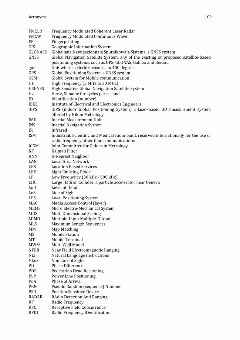
Acronyms 109
FMCLR FrequencyModulatedCoherentLaserRadarFMCW FrequencyModulatedContinuousWaveFP FingerprintingGIS GeographicInformationSystemGLONASS GlobalnajaNawigazionnajaSputnikowajaSistema,aGNSSsystemGNSS GlobalNavigationSatellite System, anyof theexistingorproposed satellite‐based
positioningsystems,suchasGPS,GLONAS,GalileoandBeidougon Unitwhereacirclemeasuresto400degreesGPS GlobalPositioningSystem,aGNSSsystemGSM GlobalSystemforMobilecommunicationHF HighFrequency(3MHzto 30 MHz)HSGNSS HighSensitiveGlobalNavigationSatelliteSystemHz Hertz,SInameforcyclespersecondID Identification(number)IEEE InstituteofElectricalandElectronicsEngineersiGPS iGPS (indoor Global Positioning System) a laser‐based 3D measurement system
offeredbyNikonMetrologyIMU InertialMeasurementUnitINS InertialNavigationSystemIR InfraredISM Industrial,ScientificandMedicalradioband,reservedinternationallyfortheuseof
radiofrequencyotherthancommunicationsJCGM JointCommitteeforGuidesinMetrologyKF KalmanFilterKNN K‐NearestNeighborLAN LocalAreaNetworkLBS LocationBasedServicesLED LightEmittingDiodeLF LowFrequency(30kHz‐500kHz)LHC LargeHadronCollider,aparticleacceleratornearGenevaLoD LevelofDetailLoS LineofSightLPS LocalPositioningSystemMAC MediaAccessControl(layer)MEMS MicroElectro‐MechanicalSystemMDS MultiDimensionalScalingMIMO Multiple‐InputMultiple‐OutputMLS MaximumLengthSequencesMM MapMatchingMS MobileStationMT MobileTerminalMWM MultiWallModelNFER NearFieldElectromagneticRangingNLI NaturalLanguageInstructionsNLoS NonLineofSightPD PhaseDifferencePDR PedestrianDeadReckoningPLP PowerLinePositioningPoA PhaseofArrivalPRN PseudoRandom(sequence)NumberPSD PositionSensitiveDeviceRADAR RAdioDetectionAndRangingRF RadioFrequencyRFC ReceptiveFieldCoocurrenceRFID RadioFrequencyIDentification

Acronyms 110
RMSD RootMeanSquareDeviationRR ResponseRateRSS ReceivedSignalStrengthRSSI ReceivedSignalStrengthIndicatorRTLS RealTimeLocatingSystemRToF RoundtripTimeofFlightRTT RoundTripTimeSDS‐TWR SymmetricalDouble‐SidedTwoWayRangingSF‐CW SteppedFrequencyContinuousWaveSHF SuperHighFrequency(3GHz‐ 30GHz)SLAM SimultaneousLocalizationAndMappingSNR SignaltoNoiseRatioSoL SafetyofLifeTDoA TimeDifferenceofArrivalToA TimeofArrivalToF TimeofFlightTTFF TimeToFirstFixTWR TwoWayRangingUHF UltraHighFrequency(300MHz‐ 3GHz)US UltraSoundUTMS UniversalMobileTelecommunicationsSystemUWB Ultra‐WidebandVHF VeryHighFrequency(30MHzto 300MHz)WLAN WirelessLocalAreaNetworkWPAN WirelessPersonalAreaNetworkWSN WirelessSensorNetworksZARU Zero‐AngularRateUpdateZUPT Zerovelocity‐UPdaTe

Symbols 111
Symbols
Symbol Expansion/Meaning Symbol Expansion/Meaning
A amplitude m numberoffingerprints estimatedvarianceofapointP n numberofpoints/nodes
aP averagepositiondeviationofpointP nm numberofmobilepositionsα averagedfastfadingterm nr numberofrangesB magneticfluxdensity ns numberofstaticnodesb bandwidth µ permeabilityc empiricalpasslosspenetrationfactor µ0 permeabilityofvacuumc RSSIcalibrationvector P positionvectorCx variance‐covariancematrix estimatedpositionc0 speedoflightinvacuum p pathlossexponentcor correlationcoefficient PR receivedpowerd distance PT transmittedpowerd vectorofdistances θ headingΔf frequencyspectrum ϕ elevationangleΔt timeinterval q numberofjointsF areaofacoil r rangef radiofrequency rr rangeresolutionf fingerprint r(t) multipathsignalGR antennagainofreceiver rt RSSIreceivedattimetGT antennagainoftransmitter s(t) transmittedsignalγ modelparameterforslowfading σ standarddeviationH magneticfieldstrength standarddeviationofpositionPh modelparameterforfastfading τ delayofapropagationpathI electriccurrent T temperaturei point/nodenumber t timej fingerprintnumber u numberofloopsofacoilk numberoffloors v velocity,speedL totalpassloss x,y,z coordinatesl steplength x statevectorλ wavelength z(t) randomnoise

References 112
References
Aalto,L.,Gothlin,N.,Korhonen,J.andOjala,T.(2004):“BluetoothandWAPPushBasedLocation‐aware Mobile Advertising System”, Proceedings of the 2nd International Conference onMobileSystems,Applications,andServices,MobiSYS’04,pp.49–58.
ABATEC(2012):http://www.abatec‐ag.com/,lastaccessed11.October2011.
AICON3DSystems(2011):http://www.aicon.de,lastaccessed14.October2011.
Alawieh,M., Patino‐Studencka, L. andDahlhaus,D. (2010): “StochasticModeling of PseudoliteClockErrorsUsingEnhancedARMethods”,ProceedingsofCSNDSP2010,pp.178–183.
Alloulah, M. and Hazas, M. (2010): “An Efficient CDMA Core for Indoor Acoustic PositionSensing”,Proceedingsofthe2010InternationalConferenceonIndoorPositioningandIndoorNavigation(IPIN),September15–17,2010CampusScienceCity,ETHZurich,Switzerland.
Ambiplex(2011):http://www.ambiplex.com/,lastaccessed14.October2011.
Arumugam,D.,Griffin,J.,Stancil,D.andRicketts,D.(2011):“HigherOrderLoopCorrectionsforShortRangeMagnetoquasistaticPositionTracking”,Proceedingsofthe2011IEEEAntennasandPropagationConference(APURSI),July2011,pp.1755–1757.
Ascension(2011):http://www.ascension‐tech.com/,lastaccessed17.May2011.
Atsuumi, K. and Sano, M. (2010): “Indoor IR Azimuth Sensor Using a Linear Polarizer”,Proceedings of the 2010 International Conference on Indoor Positioning and IndoorNavigation(IPIN),September15–17,2010CampusScienceCity,ETHZurich,Switzerland.
Aufderheide,D.andKrybus,W.(2010):“TowardsReal‐TimeCameraEgomotionEstimationandThree‐Dimensional Scene Acquisition fromMonocular Image Streams”, Proceedings of the2010 International Conference on Indoor Positioning and Indoor Navigation (IPIN),September15–17,2010CampusScienceCity,ETHZurich,Switzerland.
Bahl, P. and Padmanabhan, V. (2000): “Radar: An In‐Building RF‐based User Location andTracking System”, Proceedings of INFOCOM 2000, IEEE Conference on ComputerCommunications,TelAviv,Israel.
Bancroft, J.,Lachapelle,G.,Cannon,M.andPetovello,M. (2008): “TwinIMU‐HSGPSIntegrationfor PedestrianNavigation”, Proceedings of the 21st International TechnicalMeeting of theSatelliteDivisionofTheInstituteofNavigation(IONGNSS2008),pp.1377–1387.
Bao, L. and Intille, S. (2004): “Activity Recognition from User‐Annotated Acceleration Data”,Proceedingsofthe2ndInternationalConferenceonPervasiveComputing,pp.1–17.

References 113
Bargh,M.anddeGroote,R.(2008):“IndoorLocalizationBasedonResponseRateofBluetoothInquiries”,ACM2008,pp.49–54.
Barnes,J.,Rizos,C.,Kanli,M.,Pahwa,A.,Small,D.,Voigt,G.,GambaleN.andLamance,J.(2005):“HighAccuracyPositioningUsingLocata'sNextGenerationTechnology”,Proceedingsof the18th International Technical Meeting of The Institute of Navigation (ION GNSS 2005),pp.2049–2056.
Barnes, J., Van Cranenbroeck, J., Rizos, C., Pahwa, A. and Politi, N. (2007): “Long TermPerformance Analysis of a New Ground‐transceiver Positioning Network (LocataNet) forStructuralDeformationMonitoringApplications”,FIGWorkingWeek2007,HongKongSAR,China,13–17May2007.
Baum,M.,Niemann,B.,Abelbeck,F.,Fricke,D.‐H.andOvermeyer,L.(2007):“QualificationTestsofHFRFIDFoilTranspondersforaVehicleGuidanceSystem”,Proceedingsofthe2007IEEEIntelligentTransportationSystemsConference(ITSC2007),pp.950–955.
Beauregard,S.(2006):“AHelmet‐MountedPedestrianDeadReckoningSystem,”Proceedingsofthe3rdInternationalForumonAppliedWearableComputing(IFAWC2006),pp.15–16.
Bensky A., (2007): “Wireless Positioning Technologies and Applications”, Artech HousePublishers2007,311p.
Blankenbach, J. and Norrdine, A. (2010): “Position Estimation Using Artificial GeneratedMagnetic Fields”, Proceedings of the 2010 International Conference on Indoor Positioningand Indoor Navigation (IPIN), September 15–17, 2010 Campus Science City, ETH Zurich,Switzerland.
Bolliger, P. (2008): “Redpin – Adaptive, Zero‐Configuration Indoor Localization ThroughUserCollaboration,”ProceedingsoftheACMInternationalWorkshoponMobileEntityLocalizationandTrackinginGPS‐lessEnvironments,pp.55–60.
Boochs, F., Schütze, R., Simon, C., Marzani, F., Wirth, H. and Meier, J. (2010): “Increasing theAccuracyofUntaughtRobotPositionsbyMeansofaMulti‐CameraSystem”,Proceedingsofthe 2010 International Conference on Indoor Positioning and Indoor Navigation (IPIN),September15–17,2010CampusScienceCity,ETHZurich,Switzerland.
Bürki,B.,Guillaume,S.,Sorber,P.andOesch,H.(2010):“DAEDALUS:AVersatileUsableDigitalClip‐on Measuring System for Total Stations”, Proceedings of the 2010 InternationalConference on Indoor Positioning and Indoor Navigation (IPIN), September 15–17, 2010CampusScienceCity,ETHZurich,Switzerland.
Capps, C. (2001): “Near Field or Far Field”, in Electronic Design News (EDN), August 2001,pp.95–102.
Chen,Y.C.,Chiang, J.R.,Chu,H.,Huang,P.andTsui,A.W.(2005):“Sensor‐AssistedWi‐FiIndoorLocationSystemforAdaptingtoEnvironmentalDynamics,”ProceedingsofACMInternationalSymposiumonModeling,AnalysisandSimulationofWirelessandMobileSystems,pp.118–125.
Cheung,K.,Intille,S.andLarson,K.(2006):“AnInexpensiveBluetooth‐BasedIndoorPositioningHack”,Proceedingsofthe8thInternationalConferenceonUbiquitousComputing,ExtendedAbstracts.
Chrysikos, T., Georgopoulos, G. and Kotsopoulos, S. (2009): “Site‐Specific Validation of ITUIndoor Path Loss Model at 2.4 GHz”, 10th IEEE International Symposium on a World ofWireless,MobileandMultimediaNetworks(WoWMoM),June2009,pp.1–6.

References 114
Ciurana,M.,Lopez,D.andBarcelo‐Arroyo,F.(2009):“SofTOA:SoftwareRangingforTOA‐BasedPositioning ofWLANTerminals”, Proceedings of International Symposium of Location andContextAwareness‘09,pp.207–221.
Ciurana, M., Giustiniano, D., Neira, A., Barcelo‐Arroyo, F. and Martin‐Escalona, I. (2010):“Performance Stability of SoftwareToA‐BasedRanging inWLAN”, Proceedingsof the 2010InternationalConferenceonIndoorPositioningandIndoorNavigation(IPIN),September15–17,2010CampusScienceCity,ETHZurich,Switzerland.
Daly,D.,Melia,T.andBaldwin,G.(2010):“ConcreteEmbeddedRFIDforWay‐PointPositioning”,Proceedings of the 2010 International Conference on Indoor Positioning and IndoorNavigation(IPIN),September15–17,2010CampusScienceCity,ETHZurich,Switzerland.
Depenthal, C. (2010): “Path Tracking with iGPS”, Proceedings of the 2010 InternationalConference on Indoor Positioning and Indoor Navigation (IPIN), September 15–17, 2010CampusScienceCity,ETHZurich,Switzerland.
DeSouza, G. and Kak, A. (2002): “Vision for Mobile Robot Navigation: A Survey”, IEEETransactiononPatternAnalysisandMachineIntelligence,vol.24,no.2,pp.237–267.
Diggelen,F.(2009):“A‐GPS:AssistedGPS,GNSS,andSBAS”,ArtechHousePublishers,380p.
Dziadak, K., Sommverville, K., Kumar, B. and Green, J. (2005): “RFID Applied to the BuiltEnvironment:BuriedAssetTagging andTracking System”, Proceedings of the2ndScottishConferenceforPostgraduateResearchersoftheBuiltandNaturalEnvironment(PRoBE),16–17November2005,pp.493–504.
ECCReport‐145(2010):“RegulatoryFrameworkforGlobalNavigationSatelliteSystem(GNSS)Repeaters”, Electronic Communications Committee (ECC), St. Petersburg, May 2010,http://www.erodocdb.dk/Docs/doc98/official/pdf/ECCREP145.PDF, last accessed20.January2011.
Eissfeller, B., Teuber, A. and Zucker, P. (2005): “Indoor‐GPS: Ist der Satellitenempfang inGebäudenmöglich?”,ZfV,vol.4,pp.226–234,2005.
eRide(2011):www.eride.com,lastaccessed15.November2011.
EvAAL(2011):http://evaal.aaloa.org/,lastaccessed20.November2011.
EvolutionRobotics(2010):http://www.evolution.com,lastaccessed12.December2010.
Filonenko,V.,Cullen,C.andCarswell,J.(2010):“InvestigatingUltrasonicPositioningonMobilePhones”,Proceedingsofthe2010InternationalConferenceonIndoorPositioningandIndoorNavigation(IPIN),September15–17,2010CampusScienceCity,ETHZurich,Switzerland.
Fink, A., Beikirch, H., Voß, M. and Schröder, C. (2010): “RSSI‐based Indoor Positioning UsingDiversity and Inertial Navigation”, Proceedings of the 2010 International Conference onIndoor Positioning and Indoor Navigation (IPIN), September 15–17, 2010 Campus ScienceCity,ETHZurich,Switzerland.
Fischer, G., Klymenko, O., Martynenko, D. and Lüdiger, H. (2010): “An Impulse Radio UWBTransceiver with High‐Precision TOA Measurement Unit”, Proceedings of the 2010InternationalConferenceonIndoorPositioningandIndoorNavigation(IPIN),September15–17,2010CampusScienceCity,ETHZurich,Switzerland.
Fluerasu,A.,Jardak,N.,Picois,A.V.andSmama,N.(2011):“StatusoftheGNSSTransmitter‐BasedApproach forIndoorPositioning”,Coordinates–Positioning,NavigationandBeyond,vol.7,no.1,pp.27–30.

References 115
Frank, K., Krach, B., Catterall, N. andRobertson, P. (2009): “Development andEvaluation of aCombinedWLAN Inertial Indoor Pedestrian Positioning System”, Proceedings of the 22ndInternationalTechnicalMeetingofTheSatelliteDivisionof the InstituteofNavigation(IONGNSS2009),Savannah,Georgia,USA,pp.538–546.
Frank,M.(2008):“EineIdeenimmtGestaltan3D‐DatenvonphysischenModellenundBauteilenerzeugen”,QualitätundZuverlässigkeit(QZ),vol.53,no.12,pp.53–55.
Frick(2011):www.fricknet.com,lastaccessed23.October2011.
Fröhlich C. and Mettenleiter M. (2004): “Terrestrial Laser Scanning. New Perspective in 3D‐Surveying”,ProceedingsoftheISPRSWorkingGroupVIII/2,Freiburg,Germany,pp.7–13.
Fujimoto,M.,Nakamori, E., Inada,A.,Oda,Y.,Wada,T.,Mutsuura,K. andOkada,H. (2011): “ABroad‐Typed Multi‐Sensing‐Range Method for Indoor Position Estimation of Passive RFIDTags”, Proceedings of the2011 InternationalConference on IndoorPositioning and IndoorNavigation(IPIN),September21–23,2011inGuimarães,Portugal.
Gallagher,T.,Li,B.,Kealy,A.andDempster,A.(2009):“TrialsofCommercialWi‐FiPositioningSystemsforIndoorandUrbanCanyons”,ProceedingsofIGNSSSymposium,2009,GoldCoast,Australia.
Gallagher,T.,Li,B.,Kealy,A.,Dempster,A.andRizos,C.(2010):“ASector‐BasedCampus‐WideIndoor Positioning System”, Proceedings of the 2010 International Conference on IndoorPositioningandIndoorNavigation(IPIN),September15–17,2010CampusScienceCity,ETHZurich,Switzerland.
Gansemer,S.,Großmann,U.andHakobyan,S.(2010):“RSSI‐basedEuclideanDistanceAlgorithmfor Indoor Positioning Adapted for the Use in Dynamically ChangingWLAN Environmentsand Multi‐Level Buildings”, Proceedings of the 2010 International Conference on IndoorPositioningandIndoorNavigation(IPIN),September15–17,2010CampusScienceCity,ETHZurich,Switzerland.
GATE(2011):http://www.gate‐testbed.com/,lastaccessed30.October2011.
Golden,S.andBateman,S.(2007):“SensorMeasurementsforWi‐FiLocationwithEmphasisonTime‐of‐Arrival Ranging”, IEEE Transactions onMobile Computing vol.6, no.10, pp.1185–1198.
Grimm, D. (2012): “GNSS Antenna Orientation Based on Modification of Received SignalStrengths”,PhDDissertationatETHZürich,InstituteforGeodesyandPhotogrammetry,tobepublished.
Günther A. and Hoene, C. (2004): “Measuring Round Trip Times to Determine the DistancebetweenWLANNodes”,TechnicalReportTKN‐04–16,A.Wolisz(Editor),TelecommunicationNetworksGroup,TechnicalUniversityBerlin,43p.
Gusenbauer,D., Isert,C.andKrösche, J. (2010):“Self‐ContainedIndoorPositioningonOff‐The‐Shelf Mobile Devices”, Proceedings of the 2010 International Conference on IndoorPositioningandIndoorNavigation(IPIN),September15–17,2010CampusScienceCity,ETHZurich,Switzerland.
GustafssonF. andGunnarsson,F. (2005): “MobilePositioningUsingWirelessNetworks,” IEEESignalProcessingMagazine,vol.22,no.4,pp.41–53.
Habbecke,M.andKobbelt,L. (2008): “LaserBrush:aFlexibleDevice for3DReconstructionofIndoorScenes”,SymposiumonSolidandPhysicalModelingvol.2008,pp.231–239.
References 116
Hagisonic (2008): “User’s Guide Localization System StarGazerTM for Intelligent Robots”,http://www.hagisonic.com/,lastaccessed17.March2010.
Hansen,R.,Wind,R.,Jensen,C.andThomsen,B.(2010):“AlgorithmicStrategiesforAdaptingtoEnvironmental Changes in 802.11 Location Fingerprinting”, Proceedings of the 2010InternationalConferenceonIndoorPositioningandIndoorNavigation(IPIN),September15–17,2010CampusScienceCity,ETHZurich,Switzerland.
Hashemi,H.(1993):“TheIndoorRadioPropagationChannel,”ProceedingsofIEEE,vol.81,no.7,pp.943–968.
Hauschildt,D.andKirchhof,N.(2010):“AdvancesinThermalInfraredLocalization:ChallengesandSolutions”,Proceedingsofthe2010InternationalConferenceonIndoorPositioningandIndoor Navigation (IPIN), September 15–17, 2010 Campus Science City, ETH Zurich,Switzerland.
Hausmair,K.,Witrisal,K.,Meissner,P.,Steiner,C.andKail,G.(2010):“SAGEAlgorithmforUWBChannelParameterEstimation”,Proceedingsofthe10thCOST2100ManagementCommitteeMeeting.
Haverinen,J.andKemppainen,A.(2009):“GlobalIndoorSelf‐LocalizationBasedontheAmbientMagneticField”,JournalofRoboticsandAutonomousSystems,vol.57,no.10,pp.1028–1035.
Hazas,M.andHopper,A.(2006):“BroadbandUltrasonicLocationSystemsforImprovedIndoorPositioning”,IEEETransactionsonMobileComputing,vol.5,no.5,pp.536–547.
Hein,G.,Paonni,M.,Kropp,V.andTeuber,A.(2008):“GNSSIndoors.FightingtheFading–Part1”,InsideGNSS‐EngineeringSolutionsfortheGlobalNavigationSatelliteSystemCommunity,vol.3,no.2,March/April2008,pp.43–52.
Herrmann,R.,Sachs,J.andBonitz,F.(2010):“OnBenefitsandChallengesofPersonLocalizationUsingUltra‐WidebandSensors”,Proceedingsofthe2010InternationalConferenceonIndoorPositioningandIndoorNavigation(IPIN),September15–17,2010CampusScienceCity,ETHZurich,Switzerland.
Hexamite(2011):http://www.hexamite.com/,lastaccessed4.October2011.
Hightower,J.andBorriello,G.(2001):“LocationSystemsforUbiquitousComputing”,Computer,IEEEComputerSocietyPress,vol.34,no.8,August2001,pp.57–66.
Hile,H. andBorriello,G. (2008): “Positioning andOrientierung in IndoorEnvironmentsUsingCameraPhones”,IEEEComputerGraphicsandApplications,July/August2008,pp.32–39.
Ido,J.,Shimizu,Y.,Matsumoto,Y.andOgasawara,T.(2009):“IndoorNavigationforaHumanoidRobotUsingaViewSequence”,TheInternationalJournalofRoboticsResearch,vol.28,no.2,pp.315–325.
Ingensand, H., Bitzi, P. (2001): “Technologien der GSM‐Positionierungsverfahren”, AVN –AllgemeineVermessungs‐Nachrichten,vol.2001,no.8‐9,pp.286‐294.
InfraSurvey(2011):http://www.infrasurvey.ch/,lastaccessed12.June2011.
JCGM 200:2008 (2008): “International Vocabulary ofMetrology ‐ Basic and General ConceptsandAssociatedTerms”,3rdEdition,JointCommitteeforGuidesinMetrology,104p.
Jekeli, C. (2001): “InertialNavigation SystemswithGeodeticApplications”,WalterdeGruyter,NewYork,NY,352p.
References 117
Joseph,A.(2010):“GNSSSolutions:MeasuringGNSSSignalStrength”,InsideGNSS‐EngineeringSolutions for the Global Navigation Satellite System Community, vol. 5, no. 8, pp. 20–25,Nov/Dec2010.
Jiménez,A.R.,Prieto, J.C.,Ealo, J.L.,Guevara J. andSeco,F. (2009): “AComputerizedSystem toDeterminetheProvenanceofFindsinArchaeologicalSitesUsingAcousticSignals”,JournalofArchaeologicalScience,vol.36,no.10,pp.2415–2426.
Jiménez,A.R.,Seco,F.,Prieto,J.C.andGuevara,J.(2010):“PedestrianIndoorNavigationbyAidinga Foot‐Mounted IMU with RFID Signal Strength Measurements”, Proceedings of the 2010InternationalConferenceonIndoorPositioningandIndoorNavigation(IPIN),September15–17,2010CampusScienceCity,ETHZurich,Switzerland.
Kee,C.,Yun,D.,Jun,H.,Parkinson,B.,Pullen,S.andLagenstein,T.(2001):“Centimeter‐AccuracyIndoor Navigation Using GPS‐like Pseudolites,” vol. 12, no. 11. Advanstar CommunicationsInc.,pp.14–23.
Kee,C.,Jun,H.andYun,D.(2003):“IndoorNavigationSystemUsingAsynchronousPseudolites”,JournalofNavigation,vol.56,pp.443–455.
Kemppi, P., Rautiainen, T., Ranki, V., Belloni, F. and Pajunen, J. (2010): “Hybrid PositioningSystemCombiningAngle‐BasedLocalization,PedestrianDeadReckoningandMapFiltering”,Proceedings of the 2010 International Conference on Indoor Positioning and IndoorNavigation(IPIN),September15–17,2010CampusScienceCity,ETHZurich,Switzerland.
Keßler, C., Ascher, C. and Trommer, G. (2011): “Multi‐Sensor Indoor Navigation SystemwithVision‐ and Laser‐Based Localisation and Mapping Capabilities”, European Journal ofNavigation,vol.9,no.3,pp.4–11.
Khoshelham, K. (2010): “Automated Localization of a Laser Scanner in Indoor EnvironmentsUsing Planar Objects”, Proceedings of the 2010 International Conference on IndoorPositioningandIndoorNavigation(IPIN),September15–17,2010CampusScienceCity,ETHZurich,Switzerland.
Kiers,M.,Krajnc,E.,Dornhofer,M.andBischof,W.(2011):“EvaluationandImprovementsofanRFIDBasedIndoorNavigationSystemforVisuallyImpairedandBlindPeople”,Proceedingsof the 2011 International Conference on Indoor Positioning and Indoor Navigation (IPIN),September21–23,2011inGuimarães,Portugal.
Kim, J. and Jun, H.S. (2008): “Vision‐Based Location Positioning using Augmented Reality forIndoorNavigation”,IEEETransactiononConsumerElectronics,vol.54,no.3,pp.954–962.
Kimaldi(2011):http://www.kimaldi.com/,lastaccessed19.October2010.
King, T., Kopf, S., Haenselmann, T., Lubberger, C. and Effelsberg, W. (2006): “Compass: AProbabilistic Indoor Positioning System Based on 802.11 and Digital Compasses”,Proceedings of the First ACM International Workshop on Wireless Network Testbeds,ExperimentalEvaluationandCharacterization(WiNTECH),LosAngeles,CA,USA,September2006.
Kirschner,H.andStempfhuber,W.(2008):“TheKinematicPotentialofModernTrackingTotalStations ‐ A State of the Art Report on the Leica TPS1200+”, in: Stempfhuber, W. andIngensand,H. [Eds.], Proceedingsof the1st InternationalConferenceonMachineControl&Guidance,ETHZurich,pp.51–60.

References 118
Kitanov,A.,Biševac,S.andPetrović,I.(2007):“MobileRobotSelf‐LocalizationinComplexIndoorEnvironments Using Monocular Vision and 3D Model”, Proceedings of the IEEE/ASMEInternationalConferenceonAdvancedIntelligentMechatronics,Zürich,Switzerland.
Klingbeil,L.,Romanovas,M.,Schneider,P.,Traechtler,M.andManoli,Y.(2010):“AModularandMobileSystemforIndoorLocalization”,Proceedingsofthe2010InternationalConferenceonIndoor Positioning and Indoor Navigation (IPIN), September 15–17, 2010 Campus ScienceCity,ETHZurich,Switzerland.
Kjærgaard,M.,Blunck,H.,Godsk,T.,Toftkjær,T,Christensen,D.andGrønbæk,K.(2010):“IndoorPositioningUsingGPSRevisited”,PervasiveComputing,LectureNotes inComputerScience,vol.6030,pp.38–56.
Kocur,D.,Rovňáková,J.andŠvecová,M.(2009):“ThroughWallTrackingofMovingTargetsbyM‐Sequence UWB Radar”, in: I. J. Rudas, J. Fodor, J, Kacprzyk [Eds.]: ComputationalIntelligenceinEngineering,Springer,pp.394–364.
Köhler, M., Patel, S., Summet, J., Stuntebeck E. and G. Abowed (2007): “TrackSense:Infrastructure Free Precise Indoor Positioning Using Projected Patterns”, PervasiveComputing,LNCS,vol.4480,pp.334–350.
Kohoutek,T.K.,Mautz,R.andDonaubauer,A.(2010):“Real‐timeIndoorPositioningUsingRangeImaging Sensors”, Proceedings of SPIE Photonics Europe, Real‐Time Image and VideoProcessing,vol.7724.
Kokeisl(2011):http://www.kokeisl.net/,lastaccessed12.October2011.
Kosch,O.,Thiel,F.,Ittermann,B.andSeifert,F.(2011):“Non‐ContactCardiacGatingwithUltra‐WidebandRadarSensorsforHighFieldMRI”,Proceedingsofthe2011AnnualMeetingoftheInternationalSocietyforMagneticResonanceinMedicine(ISMRM),no.19,p.1804.
Koski, L. Perälä, T. and Piché, R (2010): “Indoor Positioning Using WLAN Coverage AreaEstimates”, Proceedings of the 2010 International Conference on Indoor Positioning andIndoor Navigation (IPIN), September 15–17, 2010 Campus Science City, ETH Zurich,Switzerland.
Kranz,M.,Fischer,C.andSchmidt,A.(2010):“AComparativeStudyofDECTandWLANSignalsfor Indoor Localization”, Proceedings of the IEEE International Conference on PervasiveComputingandCommunications(PerCom2010),pp.235–243.
Kroll,H.andSteiner,C.(2010):“IndoorUltra‐WidebandLocationFingerprinting”,Proceedingsof the 2010 International Conference on Indoor Positioning and Indoor Navigation (IPIN),September15–17,2010CampusScienceCity,ETHZurich,Switzerland.
Lachapelle, G. (2004): “GNSS Indoor Location Technologies”, Journal of Global PositioningSystemsvol.3,no.1–2,pp.2–11.
Laitinen,H. (2004): “WLANLocationMethods,”GraduateCourse Slides,University of Finland,online available at http://www.comlab.hut.fi/opetus/333/2004slides/topic33.pdf, lastaccessed3.December2011.
Lambda:4(2011):http://www.lambda4.com/EN/,lastaccessed11.October2011.
Larrañaga,J.,Muguira,L.,Lopez‐Garde,J.M.andVazquez,J.I.(2010):“AnEnvironmentAdaptiveZigBee‐Based Indoor Positioning Algorithm”, Proceedings of the 2010 InternationalConference on Indoor Positioning and Indoor Navigation (IPIN), September 15–17, 2010CampusScienceCity,ETHZurich,Switzerland.

References 119
Lee, S. and Song, J.B. (2007): “Mobile Robot Localization Using Infrared Light ReflectingLandmarks”, Proceedings of the International Conference on Control, Automation andSystems(ICCAS’07),pp.674–677.
LeicaGeosystems(2011):http://www.leica‐geosystems.ch/,lastaccessed19.December2011.
Liu,X.,Makino,H.,Kobyashi,S.andMaeda,Y.(2006):“AnIndoorGuidanceSystemfortheBlindusing Fluorescent Lights ‐ Relationship between Receiving Signal and Walking Speed",Proceedingsofthe28thIEEEEMBSConference,pp.5960–5963.
Liu, H., Darabi, H., Banerjee, P. and Liu, J. (2007): “Survey of Wireless Indoor PositioningTechniques and Systems”, IEEE Transactions on Systems, Man, and Cybernetics – Part C:ApplicationsandReviews,vol.37,no.6,pp.1067–1080.
Liu, T., Carlberg,M., Chen,G., Chen, J., Kua, J. andZakhor,A. (2010): “Indoor Localization andVisualization Using a Human‐Operated Backpack System”, Proceedings of the 2010InternationalConferenceonIndoorPositioningandIndoorNavigation(IPIN),September15–17,2010CampusScienceCity,ETHZurich,Switzerland,pp.890–899.
Liu,W.,Hu,C.,He,Q.,Meng,M.andLiu,L.(2010):“AHybridLocalizationSystemBasedonOpticsandMagnetics”, Proceedings of the International Conference onRobotics andBiomimetics,Tianjin,China,pp.1165–1169.
Locata(2011):http://www.locatacorp.com/,lastaccessed29.October2011.
Loctronix(2011):http://www.loctronix.com/,lastaccessed11.December2011.
Lukianto, C., Hönniger, C. and Sternberg, H. (2010): “Pedestrian Smartphone‐Based IndoorNavigationUsingUltraPortableSensoryEquipment”,Proceedingsofthe2010InternationalConference on Indoor Positioning and Indoor Navigation (IPIN), September 15–17, 2010CampusScienceCity,ETHZurich,Switzerland.
Mandal, A., Lopes, C.V., Givargis, T., Haghighat, A., Jurdak, R. and Baldi, P. (2005): “Beep: 3DIndoorPositioningUsingAudibleSound”,ProceedingsoftheConsumerCommunicationsandNetworkingConference(CCNC2005),IEEEXplore.
Mathiassen, K., Hanssen, L. and Hallingstad, O. (2010): “A Low Cost Navigation Unit forPositioningofPersonnelAfterLossofGPSPosition”,Proceedingsof the2010 InternationalConference on Indoor Positioning and Indoor Navigation (IPIN), September 15–17, 2010CampusScienceCity,ETHZurich,Switzerland.
Mautz,R.(2002):“SolvingNonlinearAdjustmentProblemsbyGlobalOptimization”,BollettinodiGeodesiaeScienzeAffini,vol.61,no.2,pp.123134.
Mautz, R. (2005): “Service Requirements Document (SRD)” for the EPSRC funded project“intelligent Pervasive LOcation Tracking (iPLOT)”, Final Report, unpublished document,ImperialCollegeLondon,UK,50p.
Mautz, R. and Ochieng, W.Y. (2007): “A Robust Indoor Positioning and Auto‐LocalisationAlgorithm”,JournalofGlobalPositioningSystems,vol.6,no.1,pp.38–46.
Mautz,R.,Ochieng,W.Y.,Brodin,G.,Kemp,A.(2007a):“3DWirelessNetworkLocalizationfromInconsistent Distance Observations,” Ad Hoc & SensorWireless Networks, vol. 3, no. 2–3,pp.141–170.
Mautz,R.(2009):TheChallengesofIndoorEnvironmentsandSpecificationonsomeAlternativePositioning Systems, Proceedings of the 6th Workshop on Positioning, Navigation andCommunication2009(WPNC'09),IEEEXplore,pp.29–36.

References 120
Mautz, R. and Tilch, S. (2011): “Optical Indoor Positioning Systems”, Proceedings of the 2011InternationalConferenceonIndoorPositioningandIndoorNavigation(IPIN),September21–23,2011inGuimarães,Portugal.
Maye, O., Schaeffner, J. andMaaser,M. (2006): “AnOptical Indoor Positioning System for theMass Market”, Proceedings of the 3rd Workshop on Positioning, Navigation andCommunication(WPNC'06),16March2006inHanover,Germany,IEEEXplore,pp.111–115.
Mazuelas, S.,Bahillo,A., Lorenzo,R.M., Fernandez,P., Lago, F.A.,Garcia,E.,Blas, J. andAbril, J.(2009):“RobustIndoorPositioningProvidedbyReal‐TimeRSSIValuesinUnmodifiedWLANNetworks,”IEEEJournalofSelectedTopicsinSignalProcessing,vol.3,no.5,pp.821–831.
MicrosoftKinect(2011):http://www.xbox.com/de‐DE/kinect/lastaccessed11.October2011.
Moghtadaiee,V.,Dempster,A.andLim,S.(2011):“IndoorLocalizationUsingFMRadioSignals:AFingerprinting Approach”, Proceedings of the 2011 International Conference on IndoorPositioningandIndoorNavigation(IPIN),September21–23,2011inGuimarães,Portugal.
Molisch,A.(2009):“UltrawidebandPropagationChannels”,ProceedingsofIEEE,SpecialIssueonUWB,vol.97,pp.353–371.
Mulloni, A., Wgner, D., Schmalstieg, D. and Barakonyi, I. (2009): “Indoor Positioning andNavigationwithCameraPhones”,PervasiveComputing,IEEE,vol.8,pp.22–31.
Muffert,M.,Siegemund,J.andFörstner,W.(2010):“TheEstimationofSpatialPositionsbyUsingan Omnidirectional Camera System”, Proceedings of the 2nd International Conference onMachineControl&Guidance,pp.95–104.
Muthukrishnan,K.,Koprinkov,G.,Meratnia,N.andLijding,M.(2006):“UsingTime‐of‐FlightforWLAN Localization: Feasibility Study”, Centre for Telematics and Information Technology(CTIT),UniversityofTwente,TechnicalReport,no.TR‐CTIT‐06–28.
My‐Bodyguard(2011):www.my‐bodyguard.eu,lastaccessed21.October2011.
NanotronTechnologies(2011):www.nanotron.com,lastaccessed22.October2011.
NaviFloor(2011):www.future‐shape.com/en/navifloor.html,lastaccessed22.October2011.
NikonMetrology(2011):http://www.nikonmetrology.com/,lastaccessed1.March2011.
Nilsson, J.O., Skog, I. and Händel, P. (2010): “Performance Characterisation of Foot‐MountedZUPT‐Aided INSs and Other Related Systems”, Proceedings of the 2010 InternationalConference on Indoor Positioning and Indoor Navigation (IPIN), September 15–17, 2010CampusScienceCity,ETHZurich,Switzerland.
Nishikata, H., Makino, H., Nishimori, K., Kaneda, T., Liu, X., Kobayashi, M. and Wakatsuki, D.(2011): “Basic Research of Indoor Positioning Method Using Visible Light Communicationand Dead Reckoning”, Proceedings of the 2011 International Conference on IndoorPositioningandIndoorNavigation(IPIN),September21–23,2011inGuimarães,Portugal.
Niwa,H.,Kodaka,K.,Sakamoto,Y.,Otake,M.,Kawaguchi,S.,Fujii,K.,Kanemori,Y.andSugano,S.(2008): “GPS‐BasedIndoorPositioningSystemwithMulti‐ChannelPseudolite”,ProceedingsoftheIEEEInternationalConferenceofRoboticsandAutomation(ICRA),pp.905–910.
OKI(2011):http://www.oki.com/,lastaccessed16.November2011.
Papliatseyeu, A., Kotilainen, N., Mayora, O. and Osmani, V. (2009): “FINDR: Low‐Cost IndoorPositioning Using FM Radio”, MobileWireless Middleware, Operating Systems, andApplications(2009),pp.15–26.

References 121
Patel,S.,Stuntebeck,E.andRobertson,T.(2009):"PL‐Tags:DetectingBatterylessTagsthroughthe Power Lines in a Building", Proceedings of the International Conference on PervasiveComputing(Pervasive'09),pp.257–273.
Park, J., Charrow, B., Curtis, D., Battat, J., Minkov, E., Hicks, J., Teller, S. and Ledlie, J. (2010):“Growing anOrganic Indoor Location System,” Proceedings of International Conference onMobileSystems,Applications,andServices,pp.271–284.
Parodi, B. B., Lenz, H., Szabo, A., Wang, H., Horn, J., Bamberger, J. and Obradovic J. (2006):“Initialization and Online‐Learning of RSS Maps for Indoor/Campus Localization,”ProceedingsofPositionLocationandNavigationSymposium(PLANS06), IEEE/ION,MyrtleBeach,SouthCarolinapp.24–27.
Pena,D.,Feick,R.,Hristov,H.andGrote,W.(2003):“MeasurementandModellingofPropagationLossesinBrickandConcreteWalls forthe900‐MHzBand,”IEEETransactionsonAntennasandPropagation,vol.51,no.1,pp.31–39.
Peng, J., Zhu,M. and Zhang, K. (2011): “NewAlgorithms Based on Sigma Point Kalman FilterTechniqueforMulti‐sensorIntegratedRFIDIndoor/OutdoorPositioning”,Proceedingsofthe2011 International Conference on Indoor Positioning and Indoor Navigation (IPIN),September21–23,2011inGuimarães,Portugal.
Pereira, F., Theis, C., Moreira, A. and Ricardo, M. (2011): “Evaluating Location FingerprintingMethods forUndergroundGSMNetworksdeployedoverLeakyFeeder”,Proceedingsof the2011 International Conference on Indoor Positioning and Indoor Navigation (IPIN),September21–23,2011inGuimarães,Portugal.
Pietrzyk, M. and von der Grün, T. (2010): “Experimental Validation of a TOA UWB RangingPlatform with the Energy Detection Receiver”, Proceedings of the 2010 InternationalConference on Indoor Positioning and Indoor Navigation (IPIN), September 15–17, 2010CampusScienceCity,ETHZurich,Switzerland.
Polhemus(2011):http://www.polhemus.com/,lastaccessed30.May2011.
Popescu, V., Sacks, E. and Bhamutov, G. (2004): “Interactive Modeling from Dense Color andSparse Depth”, Proceedings of Conference 3D Imaging, Modeling, Processing, VisualizationandTransmission(3DPVT),pp.430–437.
Popescu, V., Bahmutov, G., Mudure, M. and Sacks, E. (2006): “The Modelcamera”, GraphicalModels,vol.68,pp.385–401.
Popleteev, A. (2011): “Indoor Positioning Using FM Radio Signals”, PhD Dissertation at theUniversityofTrento,SchoolinInformationandCommunicationTechnologies,160p.
Povalač,A.andŠebesta, J. (2010): “PhaseofArrivalRangingMethod forUHFRFIDTagsUsingInstantaneousFrequencyMeasurement,”Proceedingsof the20th InternationalConferenceonAppliedElectromagneticsandCommunications(ICECom2010),vol.1,pp.1–4.
Pressl,B.andWieser,M.(2006):“AComputer‐BasedNavigationSystemTailoredtotheNeedsofBlindPeople”,LectureNotesinComputerScience,vol.4061,pp.1280–1286.
Priyantha, N.B. (2005): “The Cricket Indoor Location System”, PhD Thesis, MassachusettsInstituteofTechnology,199p.
Quddus, M., Ochieng, W. and Noland, R. (2007): “Current Map‐Matching Algorithms forTransport Applications: State of the Art and Future Research Directions” TransportationResearchPartC,vol.15,pp.312–328.

References 122
Rabinowitz, M. and Spilker, J. (2005): “A New Positioning System Using TelevisionSynchronizationSignals”,IEEETransactionsonBroadcasting,vol.51,no.1,pp.51‐61.
Rantakokko, J.,Händel,P., Fredholm,M. andMarsten‐Eklöf,F. (2010): “UserRequirements forLocalizationandTrackingTechnology:ASurveyofMission‐specificNeedsandConstraints”,Proceedings of the 2010 International Conference on Indoor Positioning and IndoorNavigation(IPIN),September15–17,2010CampusScienceCity,ETHZurich,Switzerland.
Reddy,H.andChandra,G.: (2007): “An ImprovedTime‐of‐ArrivalEstimation forWLAN‐BasedLocal Positioning”, Proceedings of the 2nd International Conference on CommunicationSystemsSoftwareandMiddleware(COMSWARE),January2007,pp.1–5.
Reijiniers, J. andPeremans,H. (2007): “Biomimetic SonarSystemPerformingSpectrum‐BasedLocalization”,IEEETransactionsonRobotics,vol.23,no.6,pp.1151–1159.
Reimann, R. (2011): “Locating and Distance Measurement by High Frequency RadioWaves”,Proceedings of the 2011 International Conference on Indoor Positioning and IndoorNavigation(IPIN),September21–23,2011inGuimarães,Portugal.
Renaudin, V., Yalak, O. and Tomé, P. (2007): “Hybridization of MEMS and Assisted GPS forPedestrianNavigation,”InsideGNSS,vol.2,no.1,pp.34–42.
Richardson,B., Leydon,K., Fernstrom,M. andParadiso, J. (2004): “Z‐Tiles:BuildingBlocks forModular, Pressure‐Sensing Floorspaces”, Proceedings of the ACM Conference on HumanFactorsandComputingSystems(CHI2004),pp.1529–1532.
Rimminen, H., Lndström, J., and Sepponen, R. (2009): “Positioning Accuracy andMulti‐TargetSeparationwithaHumanTrackingSystemUsingNearFieldImaging”, International JournalOnSmartSensingandIntelligentSystems,vol.2,no.1,pp.156–175.
Rimminen,H.,Lndström,J.,Linnavuo,M.andSepponen,R.(2010):“DetectionofFallsAmongtheElderly by a Floor Sensor Using the Electric Near Field”, IEEE Trans Transactions onInformationTechnologyinBiomedicinevol.14,no.6,pp.1475–1476.
Rizos,C.,Roberts,G.,Barnes, J. andGambale,N. (2010): “Locata:AnewHighAccuracy IndoorPositioningSystem”,Proceedingsofthe2010InternationalConferenceonIndoorPositioningand Indoor Navigation (IPIN), September 15–17, 2010 Campus Science City, ETH Zurich,Switzerland.
Robert, C., Tomé, P., Botteron, C., Farine, P.A., C.,Merz, R. andBlatter, A. (2010): “LowPowerASIC Transmitter for UWB‐IR Radio Communication and Positioning”, Proceedings of the2010 International Conference on Indoor Positioning and Indoor Navigation (IPIN),September15–17,2010CampusScienceCity,ETHZurich,Switzerland.
Röhr, S. and Gulden, P. (2009): “Hochpräzise Kranortung mit Millimeterwellen”,17.KranfachtagungattheTechnicalUniversityofDresden,16p.
Salo,J.,Vuokko,L.,El‐Sallabi,H.M.andVainikainen,P.(2007):“AnAdditiveModelasaPhysicalBasisforShadowFading,”IEEETransactionsonVehicularTechnology,vol.56,no.1,pp.13–26.
Sato, T., Nakamura, S., Terabayashi, K., Sugimoto, M. and Hashizume. H. (2011): “Design andImplementationof aRobustandReal‐timeUltrasonicMotion‐captureSystem”,Proceedingsof the 2011 International Conference on Indoor Positioning and Indoor Navigation (IPIN),September21–23,2011inGuimarães,Portugal.
Schantz,H.G.,Christian,W.andJohn,U.(2011):“CharacterizationofErrorinaNFERReal‐TimeLocationSystem”,ProceedingsofRadioandWirelessSymposium,IEEE,16–20January2011.

References 123
Schlaile, C.,Meister, O., Frietsch, N., Kessler, C.,Wendel, J. and Trommer, G. F. (2009): “UsingNatural Features for Vision BasedNavigation of an Indoor‐VTOLMAV”, Aerospace ScienceandTechnology,vol.13,no.7,pp.349–357.
Schmid,J.,Völker,M.,Gädeke,T.,Weber,P.,Stork,W.andMüller‐Glaser,K.(2010):“AnApproachtoInfrastructure‐IndependentPersonLocalizationwithanIEEE802.15.4WSN”,Proceedingsof the 2010 International Conference on Indoor Positioning and Indoor Navigation (IPIN),September15–17,2010CampusScienceCity,ETHZurich,Switzerland.
Schmitt, R., Nisch, S., Schönberg, A., Demeester, F. and Renders, S. (2010): “PerformanceEvaluation of iGPS for Industrial Applications”, Proceedings of the 2010 InternationalConference on Indoor Positioning and Indoor Navigation (IPIN), September 15–17, 2010CampusScienceCity,ETHZurich,Switzerland.
Schneider, O. (2010): “Requirements for Positioning and Navigation in UndergroundConstructions”,Proceedingsofthe2010InternationalConferenceonIndoorPositioningandIndoor Navigation (IPIN), September 15–17, 2010 Campus Science City, ETH Zurich,Switzerland.
Schwaighofer, A., Grigoras,M., Tresp, V. andHoffmann, C. (2003): “GPPS: A Gaussian ProcessPositioning System for Cellular Networks”, in Advances in Neural Information ProcessingSystems,2003.
Schweinzer,H.andSyafrudinS.(2010):“LOSNUS:AnUltrasonicSystemEnablingHighAccuracyand Secure TDoA Locating of Numerous Devices”, Proceedings of the 2010 InternationalConference on Indoor Positioning and Indoor Navigation (IPIN), September 15–17, 2010CampusScienceCity,ETHZurich,Switzerland.
Seco, F., Jiménez, A. R., Prieto, C., Roa J. and Koutsou, K. (2009): “A Survey of MathematicalMethods for Indoor Localization”, 6th IEEE International Symposium on Intelligent SignalProcessing(WISP2009),Budapest,Hungary,pp.9–14.
Seco, F., Plagemann, C., Jiménez, A. and Burgard, W. (2010): “Improving RFID‐Based IndoorPositioning Accuracy Using Gaussian Processes”, Proceedings of the 2010 InternationalConference on Indoor Positioning and Indoor Navigation (IPIN), September 15–17, 2010CampusScienceCity,ETHZurich,Switzerland.
Segura,M.,Hashemi,H., Sisterna,C. andMut,V. (2010): “ExperimentalDemonstrationof Self‐LocalizedUltraWidebandIndoorMobileRobotNavigationSystem”,Proceedingsofthe2010InternationalConferenceonIndoorPositioningandIndoorNavigation(IPIN),September15–17,2010CampusScienceCity,ETHZurich,Switzerland.
Seitz, J.,Vaupel,T.,Meyer,S.,GutiérrezBoronat, J.andThielecke, J. (2010): “AHiddenMarkovModel for Pedestrian Navigation,” Proceedings of the 7th Workshop on Positioning,NavigationandCommunication(WPNC’10),Dresden,Germany.
SensFloor(2011):http://www.future‐shape.com/en/,lastaccessed22.October2011.
Serant,D., Julien,O.,Ries,L.,Thevenon,P.andDervin,M.(2010):“TheDigitalTVCase”, InsideGNSS‐EngineeringSolutionsfortheGlobalNavigationSatelliteSystemCommunity,vol.6,no.6,pp.54–62,Nov/Dec2011.
Shang, Y., Ruml, W., Zhang, Y. and Fromherz, M. (2004): “Localization from Connectivity inSensor Networks”, IEEE Transactions on Parallel and Distributed Systems, vol. 15, no. 11,pp.961–974.

References 124
Shen, J., Oda, Y. (2010): “Direction Estimation for Cellular Enhanced Cell‐ID PositioningUsingMultipleSectorObservations”,Proceedingsof the2010 InternationalConferenceon IndoorPositioningandIndoorNavigation(IPIN),September15–17,2010CampusScienceCity,ETHZurich,Switzerland.
Shin, S., Kim, H.W., Park, C.G. and Yoo, Y.M. (2009): “Sit‐Down and Stand‐Up AwarenessAlgorithm for the Pedestrian Dead Reckoning,” Proceedings of the European NavigationConferenceonGlobalNavigationSatelliteSystems(ENC‐GNSS’09).
Sjö,K.,López,D.,Paul,C.,Jensfelt,P.andKragicD.(2009):“ObjectSearchandLocalizationforanIndoor Mobile Robot”, Journal of Computing and Information Technology, vol. 17, no. 1,pp.67–80.
Skog, I., Nilsson, J. O. and Händel, P. (2010): “Evaluation of Zero‐Velocity Detectors for Foot‐MountedInertialNavigationSystems”,Proceedingsofthe2010InternationalConferenceonIndoor Positioning and Indoor Navigation (IPIN), September 15–17, 2010 Campus ScienceCity,ETHZurich,Switzerland.
Skyhook(2011):www.skyhookwireless.com,lastaccessed15.November2011.
Sky‐TraxInc.(2011):http://www.sky‐trax.com/,lastaccessed22.October2011.
Solcon(2011):http://www.solcon‐systemtechnik.de/,lastaccessed22.October2011.
SoLoc (2009): “Signals of Opportunity Tracking Device”, Project Report, San Diego StateUniversity,30p.
Soloviev,A.andDickman,J.(2010):“DeeplyIntegratedGPSforIndoorNavigation”,Proceedingsof the 2010 International Conference on Indoor Positioning and Indoor Navigation (IPIN),September15–17,2010CampusScienceCity,ETHZurich,Switzerland.
Soloviev,A.andVenable,D.(2010):“WhenGNSSGoesBlind‐IntegratingVisionMeasurementsforNavigationinSignal‐ChallengedEnvironments”,GNSSInside,October2010,pp.18–29.
Song, S., Hu, C., Mao, L., Yang, W. and Meng, M. (2009): “Real Time Algorithm for Magnet’sLocalization in Capsule Endoscope”, Proceedings of the International Conference onAutomationandLogistics(ICAL’09),Shenyang,China,pp.2030–2035.
Sonitor(2011):http://www.sonitor.com/,lastaccessedOctober2011.
Steinhage, A. and Lauterbach, C. (2007) “SensFloor – Ein großflächiges Sensorsystem fürAmbient‐Assisted‐LivingAnwendungen,”Proceedingsof theMikroSystemTechnikKongress,2007,pp.1091‐1094.
Stelzer,A.,Pourvoyeur,K.andFischer,A.(2004):“ConceptandApplicationofLPM–ANovel3‐DLocal Position Measurement System”, IEEE Transactions on Microwave Theory andTechniques,vol.52,no.12,pp.2664–2669.
Stoica, L., Rabbachin, A. and Oppermann, I. (2006): „A Low‐Complexity Noncoherent IR‐UWBTransceiverArchitecturewithTOAEstimation”,IEEETransactionsonMicrowaveTheoryandTechniques,vol.54,no.4,April2006,pp.1637–1646.
Stone, W. (1997): “Electromagnetic Signal Attenuation in Construction Materials”, NISTReport6055,NationalInstituteofStandards,Gaithersburg,Maryland,no.185,8p.
Sun,Z.,Mao,X.,Tian,W.andZhang,X. (2009): “ActivityClassificationandDeadReckoning forPedestrian Navigation with Wearable Sensors,” Measurement Science and Technology,vol.20,no.1,2009,pp.1–10.

References 125
Stuntebeck, E., Patel, S., Robertson, T., Reynolds, M. and Abowd, G. (2008): "WidebandPowerLine Positioning for Indoor Localization", International Conference on UbiquitousComputing(UbiComp'08),pp.94–103.
Symeo(2011):http://www.symeo.com/,lastaccessed26.February2011.
Tadakamadla, S. (2006): "Indoor Local Positioning System for Zigbee Based on RSSI", M.Sc.ThesisReport,MidSwedenUniversity,50p.
Tappero, F. (2009): “Low‐Cost Optical‐Based Indoor Tracking Device for Detection andMitigationofNLOSEffects”,ProcediaChemistry,Elsevier,vol.1,no.1,pp.497–500.
Tappero,F.,Merminod,B.andCiurana,M.(2010):“IEEE802.11RangingandMulti‐laterationforSoftware‐DefinedPositioningReceiver”,Proceedingsofthe2010InternationalConferenceonIndoor Positioning and Indoor Navigation (IPIN), September 15–17, 2010 Campus ScienceCity,ETHZurich,Switzerland.
TeuberA.andEissfeller,B.(2006):“WLANIndoorPositioningBasedonEuclideanDistancesandFuzzy Logic,” Proceedings of the 3rd Workshop on Positioning, Navigation andCommunication(WPNC’06),Hannover,Germany.
Tilch,S.andMautz,R.(2010):“DevelopmentofaNewLaser‐Based,OpticalIndoorPositioningSystem”,Proceedingsof the ISPRSCommissionVMid‐TermSymposiumCloseRange ImageMeasurementTechniques,no.98,pp.575–580.
Trimble (2011): http://www.trimble.com/mining/Terralite‐XPS‐Solutions/, last accessed31.October2011.
Trucco, E. andPlakas,K. (2006): “VideoTracking:AConcise Survey”, IEEE Journal ofOceanicEngineering,vol.31,no.2,pp.520–529.
Ubisense(2011):http://www.ubisense.net/en/,lastaccessed4.February2011.
Uchitomi, N., Inada, A., Fujimoto, M.,Wada, T., Mutsuura, K. and Okada, H. (2010): “AccurateIndoor Position Estimation by Swift‐CommunicationRangeRecognition (S‐CRR)Method inPassive RFID systems”, Proceedings of the 2010 International Conference on IndoorPositioningandIndoorNavigation(IPIN),September15–17,2010CampusScienceCity,ETHZurich,Switzerland.
Valtonen,M.,MäentaustaJ.andVanhalaJ.(2009):“TileTrack:CapacitiveHumanTrackingUsingFloorTiles”,ProceedingsoftheSeventhAnnualIEEEInternationalConferenceonPervasiveComputingandCommunications,2009,pp.31–40.
Varshavsky, A., de Lara, E., LaMarca, A., Hightower, J. and Otsason, V., (2007): “GSM IndoorLocalization”,PervasiveandMobileComputingJournal(PMC),Elsevier,vol.3,no.6,pp.698–720.
Vaupel, T., Seitz, J., Kiefer, F., Haimerl, S. and Thielecke, J. (2010): “Wi‐Fi Positioning: SystemConsiderationsandDeviceCalibration”,Proceedingsofthe2010InternationalConferenceonIndoor Positioning and Indoor Navigation (IPIN), September 15–17, 2010 Campus ScienceCity,ETHZurich,Switzerland.
Vervisch‐Picois, A., Samama, N. (2009): “Indoor Carrier Phase Measurements through GNSSTransmitters Theory and First Experimental Results”, Proceedings of the Congress of theInternationalAssociationofInstitutesofNavigation(IAIN2009),Stockholm,Sweden.
Wagner, J., Isert, C., Purschwitz, A. and Kistner, A. (2010): “Improved Vehicle Positioning forIndoorNavigationinParkingGaragesThroughCommerciallyAvailableMaps”,Proceedingsof

References 126
the 2010 International Conference on Indoor Positioning and Indoor Navigation (IPIN),September15–17,2010CampusScienceCity,ETHZurich,Switzerland.
Walder, U. and Bernoulli, T. (2010): “Context‐Adaptive Algorithms to Improve IndoorPositioning with Inertial Sensors”, Proceedings of the 2010 International Conference onIndoor Positioning and Indoor Navigation (IPIN), September 15–17, 2010 Campus ScienceCity,ETHZurich,Switzerland.
Wan,E. andPaul,A. (2010): “ATag‐freeSolution toUnobtrusive IndoorTrackingUsingWall‐mounted Ultrasonic Transducers”, Proceedings of the 2010 International Conference onIndoor Positioning and Indoor Navigation (IPIN), September 15–17, 2010 Campus ScienceCity,ETHZurich,Switzerland.
Wan,S.andFoxlin,E.(2010):“ImprovedPedestrianNavigationBasedonDrift‐ReducedMEMSIMUChip”,Proceedingsof ION2010 InternationalTechnicalMeeting, January25–27,2010,SanDiego,California,pp.365–374.
Wang, S., Waadt, A., Burnic, A., Dong Xu, Kocks, C., Bruck, G.H. and Jung, P. (2010): "SystemImplementation Study on RSSI Based Positioning in UWB Networks", 7th InternationalSymposiumonWirelessCommunicationSystems(ISWCS),pp.36–40.
Want,R.,Hopper,A.,Falcão,V.andGibbons,J.(1992):“TheActiveBadgeLocationSystem”,ACMTransactionsonInformationSystems,vol.10,no.1,pp.91–102.
Ward, A., Jones, A. and Hopper, A. (1997): “A New Location Technique for the Active Office”,PersonalCommunications,IEEE,vol.4,no.5,October1997,pp.42–47.
Weber, M., Birkel, U., Collmann, R. and Engelbrecht, J. (2011): “Wireless Indoor Positioning:Localization Improvements with a Leaky Coaxial Cable”, Proceedings of the 2011InternationalConferenceonIndoorPositioningandIndoorNavigation(IPIN),September21–23,2011inGuimarães,Portugal.
Wieser,A.(2006):“High‐SensitivityGNSS:TheTrade‐OffbetweenAvailabilityandAccuracy”,in:Kahmen H. and Chrzanowski A. [Eds.] Proceedings of the 3rd IAG / 12th FIG Symposium,Baden,Austria.
Wirola,L.,Laine,T.andSyrjärinneJ.(2010):“MassMarketConsiderationsforIndoorPositioningandNavigation”,Proceedingsofthe2010InternationalConferenceonIndoorPositioningandIndoor Navigation (IPIN), September 15–17, 2010 Campus Science City, ETH Zurich,Switzerland.
Wong, C., Klukas, R. andMessier, G. (2008): “UsingWLAN Infrastructure for Angle‐of‐ArrivalIndoorUserLocation”,ProceedingsoftheIEEEVehicularTechnologyConference,VTC2008‐Fall,pp.1–5,Calgary,BC,September2008.
Xiang,Z.,Song,S.,Chen,J.,Wang,H.,Huang,J.andGao,X.(2004):“AWirelessLAN‐BasedIndoorPositioningTechnology”,JournalofResearchDevelopment,vol.48,no.5/6,pp.617–626.
Yick, J, Mukherjee, B. and Ghosal, D. (2008): “Wireless Sensor Network Survey”, ComputerNetworks,vol.52,no.12,pp.2292–2330.
Yokoo,K., Beauregard, S. and Schneider,M. (2009): "IndoorRelativeLocalizationwithMobileShort‐RangeRadar",ProceedingsoftheVehicularTechnologyConference(VTC’09),pp.1–5.
Zhang,J.,Li,B.,Dempster,A.andRizosC.(2011):“EvaluationofHighSensitivityGPSReceivers”,Coordinates–Positioning,NavigationandBeyond,vol.7,no.3,pp.7–12.
ZebraEnterpriseSolutions(2011):http://zes.zebra.com/lastaccessed25.February2011.

References 127
Zetik, R., Shen, G. and Thomä, R. (2010): “Evaluation of Requirements for UWB LocalizationSystems in Home‐Entertainment Applications”, Proceedings of the 2010 InternationalConference on Indoor Positioning and Indoor Navigation (IPIN), September 15–17, 2010CampusScienceCity,ETHZurich,Switzerland.
ZONITH(2011):http://www.zonith.com/products/ips/,lastaccessed21.October2011.