indian standard
TRANSCRIPT

Indian StandardEARTHQUAKE RESISTANT DESIGN ANDCONSTRUCTION OF BUILDINGS

TYPES OF CONSTRUCTIONThe types of construction usually adopted in buildings are as follows:
a) Framed construction, and
b) Box type construction.
Framed Construction::
This type of construction is suitable for multistoried and industrial buildings
• Vertical Load Carrying Frame Construction
• Moment Resistant Frames with Shear Walls
Vertical Load Carrying Frame Construction
• This type of construction consists of frames with flexible (hinged) joints and bracing members. Steel multistoried building or industrial frames and timber construction usually are of this type.
• Such buildings shall be adequately strengthened against lateral forces by shear walls and/or other bracing systems in plan, elevation and sections such that earthquake forces shall be resisted by them in any direction.
TYPES OF CONSTRUCTION
Moment Resistant Frames with Shear Walls::
• The frames may be of reinforced concrete or steel with semi-rigid or rigid joints. The walls are rigid capable of acting as shear walls and may be of reinforced concrete or of brickwork reinforced or unreinforced bounded by framing members through shear connectors.
• The shear walls shall preferably be distributed evenly over the whole building. When concentrated at one point, forming what is called a rigid core in the building, the design shall be checked for torsional effects and the shear connection between the core and the floors conservatively designed for the total shear transfer.
• The shear walls should extend from the foundation either to the top of the building or to a lesser height as required from design consideration. In design, the interaction between frame and the shear walls should be considered properly to satisfy compatibility and equilibrium conditions.

TYPES OF CONSTRUCTION
Box type construction.
• This type of construction consists of prefabricated or in situ masonry, concrete or reinforced concrete wall along both the axes of the building. The walls support vertical loads and also act as shear walls for horizontal loads acting in any direction. All traditional masonry construction falls under this category. In prefabricated construction attention shall be paid to the connections between wall panels sothat transfer of shear between them is ensured.

CATEGORIES OF BUILDINGS
For the purpose of specifying the earthquake resistant features in masonry and wooden buildings, the buildings have been categorized in five categories A to E based on the seismic zone and the importance of building I, where
I = importance factor applicable to the building
The building categories are given in Table::

MASONRY CONSTRUCTION WITHRECTANGULAR MASONRY UNITS
Masonry Units:-
• Well burnt bricks or solid concrete blocks having a crushing strength not less than 3.5 MPa shall be used.
• The strength of masonry unit required shall depend on the number of storeys and thickness of walls
• Squared stone masonry, stone block masonry or hollow concrete block masonry of adequate strength, may also be used.
Mortar:-
• Mortars, such as those given in
Table or of equivalent specification,
shall preferably be used for masonry
construction for various categories
of buildings.

MASONRY CONSTRUCTION WITHRECTANGULAR MASONRY UNITSMortar:-
• Where steel reinforcing bars are provided in masonry the bars shall be embedded with adequate cover in cement sand mortar not leaner than 1: 3 (minimum clear cover 10 mm) or in cement concrete of grade M15 (minimum clear cover 15 mm or bar diameter whichever more), so as to achieve good bond and corrosion resistance.
Walls:-
• Masonry bearing walls built in mortar shall not be built of greater height than 15 m subject to a maximum of four storey's.
• The masonry bearing walls shall be reinforced in accordance with.
• The bearing walls in both directions shall be straight and symmetrical in plan as far as possible.
• The wall panels formed between cross walls and floors or roof shall be checked for their strength in bending as a plate or as vertical strip subjected to the earthquake force acting on its own mass.
MASONRY CONSTRUCTION WITHRECTANGULAR MASONRY UNITS
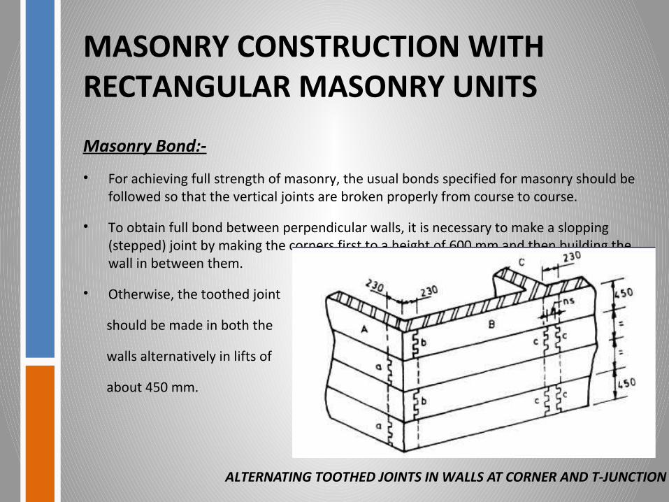
Masonry Bond:-
• For achieving full strength of masonry, the usual bonds specified for masonry should be followed so that the vertical joints are broken properly from course to course.
• To obtain full bond between perpendicular walls, it is necessary to make a slopping (stepped) joint by making the corners first to a height of 600 mm and then building the wall in between them.
• Otherwise, the toothed joint
should be made in both the
walls alternatively in lifts of
about 450 mm.
ALTERNATING TOOTHED JOINTS IN WALLS AT CORNER AND T-JUNCTION

MASONRY CONSTRUCTION WITHRECTANGULAR MASONRY UNITS
Openings in Bearing Walls:-
• Door and window openings in walls reduce their lateral load resistance and hence, should preferably be small and more centrally located. The guidelines on the size and position of opening are given in Table and FIG.
Table showing Size and Position of Openings in Bearing Walls

MASONRY CONSTRUCTION WITHRECTANGULAR MASONRY UNITSOpenings in Bearing Walls:-
FIG showing Dimensions of openings and piers for recommendations in Table.

MASONRY CONSTRUCTION WITHRECTANGULAR MASONRY UNITS
• Seismic Strengthening Arrangements:-
All masonry buildings shall be strengthened by the methods, as specified for various categories of buildings. The overall strengthening arrangements to be adopted for category D and E buildings which consist of horizontal bands of reinforcement at critical levels, vertical reinforcing bars at corners, junctions of walls and jambs of opening.
• Lintel band is a band provided at lintel level on all load bearing internal, external longitudinal and cross walls.
• Roof band is a band provided immediately below the roof or floors.
• Gable band is a band provided at the top of gable masonry below the purlins. This band shall be made continuous with the roof band at the eaves level.

MASONRY CONSTRUCTION WITHRECTANGULAR MASONRY UNITS
STRENGTHENING MASONRY AROUND OPENING
Strengthening Arrangements Recommended for Masonry BuildingsOVERALL ARRANGEMENT OF REINFORCING
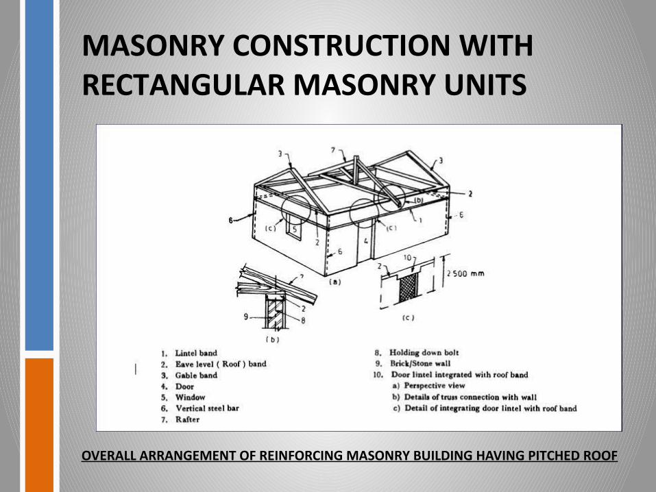
MASONRY CONSTRUCTION WITHRECTANGULAR MASONRY UNITS
OVERALL ARRANGEMENT OF REINFORCING MASONRY BUILDING HAVING PITCHED ROOF

MASONRY CONSTRUCTION WITHRECTANGULAR MASONRY UNITS
• REINFORCEMENT:-
In category D and E buildings, to further iterate the box action of walls steel dowel bars may be used at corners and T-junctions of walls at the sill level of windows to length of 900 mm from the inside corner in each wall. Such dowel may be in the form of U stirrups 8 mm dia. Where used, such bars must be laid in 1 : 3 cement-sand-mortar with a minimum cover of 10 mm on all sides to minimize corrosion.
REINFORCEMENT AND BENDING DETAIL IN R. C. BAND

MASONRY CONSTRUCTION WITHRECTANGULAR MASONRY UNITS
Framing of Thin Load Bearing Walls:-
• Load bearing walls can be made thinner than 200 mm say 150 mm inclusive of plastering on both sides.
• Reinforced concrete framing columns and collar beams will be necessary to be constructed to have full bond with the walls.
• Columns are to be located at all corners and junctions of walls and spaced not more than 1.5 m apart but so located as to frame up the doors and windows.
FRAMING OF THIN LOAD-BEARING BRICK WALLS

MASONRY CONSTRUCTION WITHRECTANGULAR MASONRY UNITSReinforcing Details for Hollow Block Masonry;-
• The following details may be followed in placing the horizontal and vertical steel in hollow block masonry using cement-sand or cement-concrete blocks.

FLOORS/ROOFS WITH SMALL PRECAST COMPONENTS
Types of Precast Floors/Roofs:-
Earthquake resistance measures for floors and roofs with small precast components, as covered in this standard, have been dealt with as typical examples.
a) Precast Reinforced Concrete Unit Roof/Floor
b) Precast Reinforced Concrete Cored Unit Roof/Floor
c) Precast Reinforced Concrete Plank and
d) Joist Scheme for Roof/Floor
e) Prefabricated Brick Panel System for Roof/Floor
f) Precast Reinforced Concrete Waffle Unit Roof/Floor

FLOORS/ROOFS WITH SMALL PRECAST COMPONENTS
Precast Reinforced Concrete Unit Roof/Floor:-
• The nominal width of the unit varies from 300 to 600 mm, its height from 150 to 200 mm and a minimum flange thickness of 30 mm.
• Length of unit shall vary according to room dimensions, but the maximum length is restricted to 4.2 m from stiffness considerations.

FLOORS/ROOFS WITH SMALL PRECAST COMPONENTSPrecast Reinforced Concrete Cored Unit Roof/Floor:-
• The unit is a reinforced concrete component having a nominal width of 300 to 600 mm and thickness of 130 to 150 mm having two circular hollows 90 mm diameter, throughout the length of the unit.
• The minimum flange/web thickness of the unit shall be
20 mm.
• Length of unit varies according to room dimensions,
but the maximum length shall be restricted to 4.2 m from
stiffness considerations.

FLOORS/ROOFS WITH SMALL PRECAST COMPONENTSPrecast Reinforced Concrete Plank and Joist Scheme for Roof/Floor:-
• The scheme consists of precast reinforced concrete planks supported on partially precast reinforced concrete joists.
• The reinforced concrete planks are 300 mm wide and the length varies according to the spacing of the joists, but it shall not exceed 1.5 m.
• To provide monolithicity to the roof/floor and to have T-beam effect with the joists, the planks shall be made partially 30 mm thick and the partially 60 mm thick and in-situ concrete shall be filled in the depressed portions to complete the roof/floor structurally.

FLOORS/ROOFS WITH SMALL PRECAST COMPONENTSPrefabricated Brick Panel System for Roof/Floor:-
• It consists of prefabricated reinforced brick panels supported on precast reinforced concrete joists with nominal reinforced 35 mm thick structural deck concrete over the brick panels and joists.
• The width of the brick panels shall be 530 mm for panels made of bricks of conventional size and 450 mm for panels made
• of bricks of modulus size.
• The thickness of the panels shall be 75 mm or 90 mm respectively depending upon whether conventional or modular bricks are used.
• The length of the panels shall vary depending upon the spacing of the joists, but the maximum length shall not exceed 1.2 m.

FLOORS/ROOFS WITH SMALL PRECAST COMPONENTS
• Precast Reinforced Concrete Waffle Unit Roof/Floor:-
• Waffle units are of the shape of inverted troughs, square or rectangular in plan, having lateral dimensions up to 1.2 m and depth depending upon the span of the roof/floor to be covered.
• The minimum thickness of flange/web shall be 35 mm.

FLOORS/ROOFS WITH SMALL PRECAST COMPONENTS
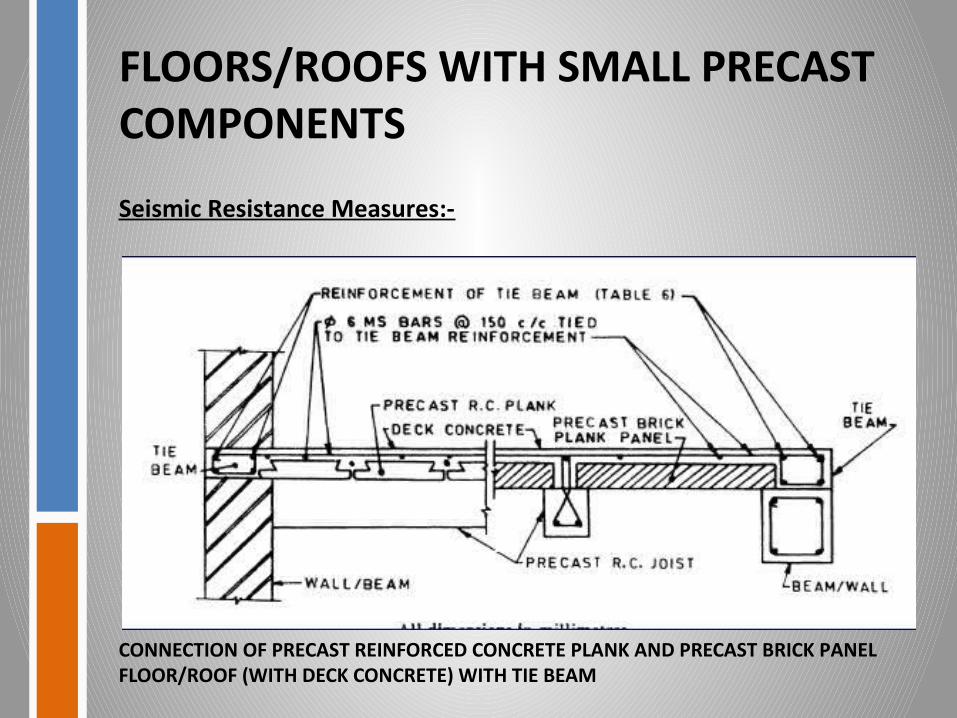
Seismic Resistance Measures:-
CONNECTION OF PRECAST CORED/CHANNEL UNIT WITH TIE BEAM

FLOORS/ROOFS WITH SMALL PRECAST COMPONENTS
Seismic Resistance Measures:-
CONNECTION OF CHANNEL/CORED UNIT FLOOR/ROOF (WITH DECK CONCRETE) WITH TIE BEAM
FLOORS/ROOFS WITH SMALL PRECAST COMPONENTS
Seismic Resistance Measures:-
CONNECTION OF PRECAST REINFORCED CONCRETE PLANK AND PRECAST BRICK PANEL FLOOR/ROOF (WITH DECK CONCRETE) WITH TIE BEAM

FLOORS/ROOFS WITH SMALL PRECAST COMPONENTS
Seismic Resistance Measures:-
CONNECTION OF PRECAST WAFFLE UNIT FLOOR/ROOF (WITH DECK CONCRETE) WITH TIE BEAM

TIMBER CONSTRUCTION
• Timber has higher strength per unit weight and is, therefore, very suitable for earthquake resistant construction.
• Timber construction shall generally be restricted to two storeys.
• In timber construction attention shall be paid to fire safety against electric short-circuiting, kitchen fire, etc.
• The superstructure of timber buildings shall be made rigid against deformations by adopting suitable construction details at the junctions of the framing members and in wall panels.

TIMBER CONSTRUCTION
Foundations:-
• Timber construction shall preferably start above the plinth level, the portion below being in masonry or concrete.
• The superstructure may simply rest on the plinth masonry, or in the case of small buildings of one storey having plan area less than about 50 m2, it may rest on firm plane ground so that the building is free to slide laterally during ground motion.
TIMBER CONSTRUCTION
Types of Framing:-
The types of construction usually adopted in timber buildings are as follows:
a) Stud wall construction, and
b) Brick nogged timber frame construction.
TIMBER CONSTRUCTIONStud Wall Construction:-
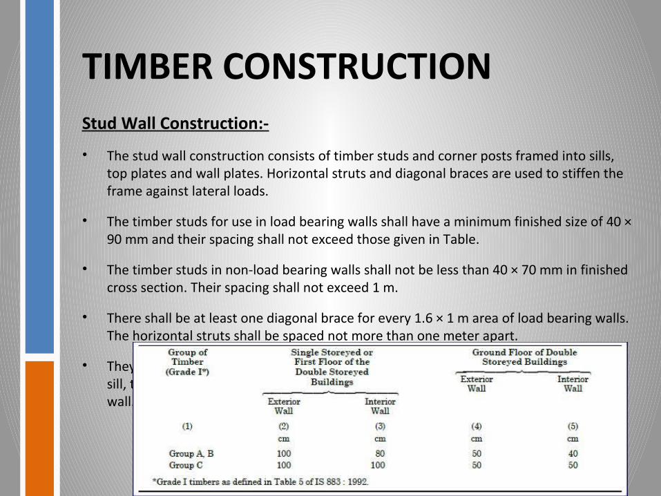
• The stud wall construction consists of timber studs and corner posts framed into sills, top plates and wall plates. Horizontal struts and diagonal braces are used to stiffen the frame against lateral loads.
• The timber studs for use in load bearing walls shall have a minimum finished size of 40 × 90 mm and their spacing shall not exceed those given in Table.
• The timber studs in non-load bearing walls shall not be less than 40 × 70 mm in finished cross section. Their spacing shall not exceed 1 m.
• There shall be at least one diagonal brace for every 1.6 × 1 m area of load bearing walls. The horizontal struts shall be spaced not more than one meter apart.
• They will have a minimum size of 30 × 40 mm for all locations. The finished sizes of the sill, the wall plate and top plate shall not be less than the size of the studs used in the wall.

TIMBER CONSTRUCTION
STUD WALL CONSTRUCTION

TIMBER CONSTRUCTION
Brick Nogged Timber Frame Construction:-
• The brick nogged timber frame consists of intermediate verticals, columns, sills, wall plates, horizontal nogging members and diagonal braces framed into each other and the space between framing members filled with tight-fitting brick masonry in stretcher bond.
• The vertical framing members in brick nogged load bearing walls will have minimum finished sizes as specified in Table.
• The minimum finished size of the vertical members in non-load bearing walls shall be 40 mm × 100 mm spaced not more than 1.5 m apart.
• The sizes of diagonal bracing members shall be the same as in Table.

TIMBER CONSTRUCTION
• The horizontal framing members in brick-nogged construction shall be spaced not more than 1 m apart. Their minimum finished sizes shall be in accordance with Table.
• The finished sizes of the sill, wall plate and top plate shall be not less than the size of the vertical members used in the wall.
• Corner posts shall consist of three vertical timbers.
• The diagonal braces shall be connected at their ends with the other members of the wall by means of wire nails.

TIMBER CONSTRUCTIONNotching and Cutting:-
• Timber framing frequently requires notching and cutting of the vertical members.
• The notching or cutting should in general be limited to 20 mm in depth unless steel strips are provided to strengthen the notched face of the member.
• Such steel strips, where necessary, shall be at least 1.5 mm thick and 35 mm wide extending at least 15 cm beyond each side of the notch or cut and attached to the vertical member by means of bolts or screws at each end.

Thank you…….
PRESENTED By:-
11617, 11631
Resources :: is.4326.1993 Google