india case study delhi metro
TRANSCRIPT

Slide 1
INDIA’S FIRST TETRA NETWORKby Delhi Metro Railway Corporation(DMRC)
TETRA Delhi SeminarSeptember 2008
Prashant RaoChief Signal & Telecomm Engineer

Slide 2
Delhi – the need for a mass transit system
• As cities grow in size, the number of vehicular trips on road system goes up. This requires a pragmatic policy shift to discourage private modes and encourage public transport.
• Delhi has experienced phenomenal growth in population in the last few decades. Its population has increased from 6 million in 1981 to almost 15 million today.
• For want of an efficient mass transport system, the number of motor vehicles had increased from 0.5 million in 1981 to more than 4 million today.
• The result is extreme congestion on Delhi roads, ever slowing speeds, increase in road accidents fuel wastage and environmental pollution with motorized vehicles alone contributing to about two thirds of the atmospheric pollution.

Slide 3
DMRC today• DMRC was then given a mandate to
construct >50 kms of Metro Rail tracks in Delhi by 2005
• Work started in 1998, and the first section of Line 1 opened on 25 Dec 2002
• DMRC today consists of 3 operational lines, which concluded the Phase1 of the Project
• Proven to be a tremendous success in meeting its aims of reducing road congestion, stimulating economic development within the proximity of the stations .
• The success of Delhi Metro has inspired greater support for mass transit systems in India (e.g. Mumbai, Bangalore, Hyderabad)
Slide 4
Slide 5
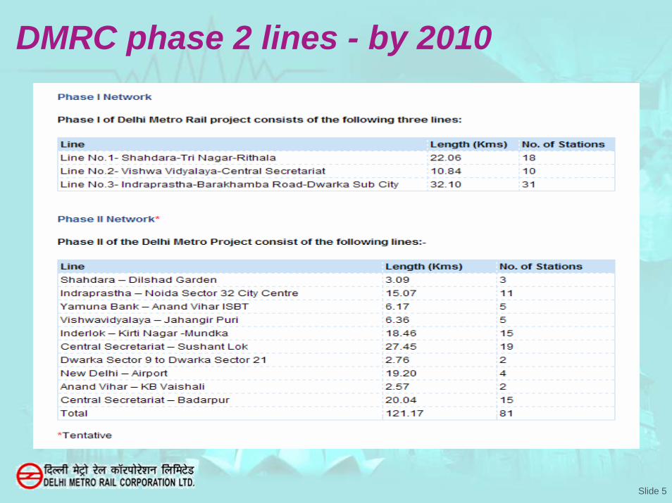
DMRC phase 2 lines - by 2010

Slide 6
Metro Rails Major Building Blocks
• The Structures-Stations, Tunnels, Elevated Via-Duct
• The Rail Track
• The Rolling Stock
• Electrical Systems- Traction and Low Voltage Supply
• Train Control & Signaling Systems
• Telecommunication Systems
• Ticketing Systems

Slide 7
Radio system Requirement
• Train to Controller Communication
• Operations & Maintenance Personnel
• Security Staff

Slide 8
Why TETRA• TETRA was selected as the radio technology for the following
reasons:– Open Standards
• Guaranteed minimum performance (~ 500 ms setup time)• Provides evolutionary growth• Sourcing from more than one vendor• Competitive pricing
– Frequency efficient– Group & Private Call– Integrated voice and data– Full Duplex– Resilience
• Site Trunking• DMO

Slide 9
DMRC Radio System• Operational from 2002
• Digital Trunked Radio System operating in 380-400 MHz conforming to ETSI TETRA standard
– Calling of Train by Train Identity Number (TID) – Customized GUI Screen for Dispatch Operator– Train Radio Control Panel for train drivers– Interfaces to other Telecommunication Subsystems
• FOTS (fibre optic transmission system), • PA (public address), • EPABX • TC&S (Train Control & Signalling).
• Thales (Line 1&2) and Siemens (Line 3) supplied the telecommunication system including the radio system.
– Motorola was selected as the sub-supplier to provide the TETRA integrated digital radio system for these Lines.
• Further for Phase 2 Network also Motorola is contracted to supply the TETRA radio system for the upcoming 100 km

Slide 10
System Sizing
• Phase 1
– Central Network Equipment (SwMi) at Master Site
– 15 Radio Base Stations – 12 Customized GUI
Dispatchers– 120 Trainborne Mobile
Radios• Mobile Radio, Train
Control Interface, Radio Control Panel
– 60 Fixed Radios • Standard Mobile Radio
installation– 500 Portable Radios
Phase 2– Standby Central Network
Equipment (SwMi) – 19 Radio Base Stations – 17 Customized GUI
Dispatchers– 248 Trainborne Mobile
Radios• Mobile Radio, Train
Control Interface, Radio Control Panel
– 122 Fixed Radios • Standard Mobile Radio
installation– 600 Portable Radios

Slide 11
Slide 12
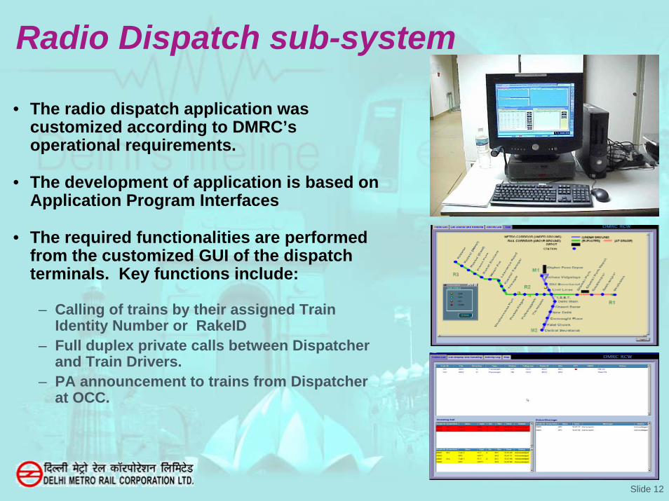
Radio Dispatch sub-system
• The radio dispatch application was customized according to DMRC’soperational requirements.
• The development of application is based on Application Program Interfaces
• The required functionalities are performed from the customized GUI of the dispatch terminals. Key functions include:
– Calling of trains by their assigned Train Identity Number or RakeID
– Full duplex private calls between Dispatcher and Train Drivers.
– PA announcement to trains from Dispatcher at OCC.

Slide 13
Trainborne equipment• Implemented in front and rear cab• Operating in main and standby
• Direct PA announcement from OCC to train passengers
– In case of Emergency (e.g. driver incapacitated), Controller can make direct announcement inside Train
– Implemented by interfacing on-board radio to on-board PA
• Radio to station PA announcement– In Emergencies - Portable to
Station PA announcement facility (Fire, Evacuation, etc)
– Good quality Voice due to inherent improved quality of TETRA
– Can select a Particular Station Number and a particular Zone
– Implemented by radio Interface to EPABX and further EPABX interface to PA
Handset
DisplayRadioPanel

Slide 14
I/O
CPU
DC/DC
TRIU
I/O
CPU
DC/DC
TRIU
TRCP
MRMR
TRCP
Fall Back Link
•Trainborne Radio Equipment consists of
Mobile RadioTrain Radio Control PanelTrain Radio Interface Unit
•Implemented in the Front and Rear cab
•Fall Back connection to Rear cab
•Operating in the standby mode to the Front cab
Trainborne Radio Equipment Architecture

Slide 15
Radio Coverage in Underground
• Is by Leaky Coaxial (LCX) Cables and Indoor Antennas
• Bi-directional Amplifiers(BDA)/ RF-Optical Repeaters provided at every station ,feeding cables into tunnels and station areas.
• LCX cables are also provided of GSM/CDMA operators for Mobile coverage

Slide 16Slide 18
Power Splitter
1:2
Station1 Station 3Station2 Station N
BDA BDA
CN
PS
BTS
StationNetwork
StationNetwork
StationNetwork
Further ext
BDA BDA BDA
DC Blocs DC Blocs DC BlocsBDA

Slide 17
Radio CNE
Slide 18
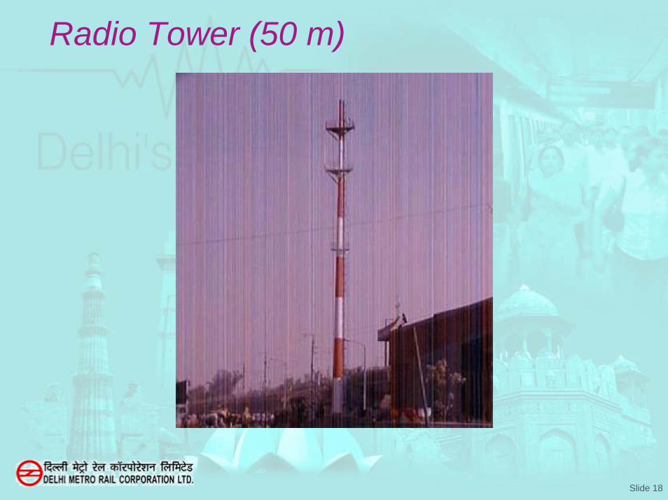
Radio Tower (50 m)

Slide 19
Remote Base Station (BTS)

Slide 20
STATION RADIO PHONE

Slide 21
Conclusion• TETRA communication system has been
implemented successfully
• The signals are clear
• The voice clarity is excellent
• The TETRA technology effectively meets DMRC’s operational and functional expectations

Slide 22
THANK YOU