index: fittings, flanged pipes and valves made of ductile cast
TRANSCRIPT

Fittings, flanged pipes and valves made of
ductile cast iron
Index: (click with mouse)
Düker in general
Preamble
The complete product range –> Index
Location plan
We designed the electronic version of our product catalogue user-friendly.
In addition to useful information you will find the complete product range of Düker “fittings and valves”.
To see each detailed information, please click on the desired category within the index.
To get back to the Index please click on the blue area (chapter) at the top margin.
http://www.dueker.de
FITTINGS AND VALVES
Fittings, Flanged pipes andValves made of Ductile Cast Iron

© 09.2018 E
Hauptstraße 39–41, 63846 Laufach, Germany
All rights reserved, including copying as a whole or in part.
Deviations in dimensions and weights and in the illustrations are possible. In the interest of technical progress, we reserve the right to implement changes and improvements to the products without previous announcement.
Düker GmbHHauptstraße 39 – 41, 63846 Laufach, GermanyPhone: + 49 6093 87-560 Telefax: + 49 6093 87-8560e-mail: [email protected] Internet: www.dueker.de
Member ofFGR / EADIPS association
Back to summary

76
Düker GmbH
As early as in 1469, official documents mentioned a mine, which developed more or less continually into today’s company Düker.The foundry and enamelling works cover a production area of more than 80,000 square meters with approx. 620 employees.
At Laufach / Spessart and Karlstadt / Main, Düker manufactures products used in:
Drainage technology• Hubless drainage pipe systems• couplings for hubless drainage pipe systems Underground construction• flanged pressure pipes• fittings and• valves Jobbing foundry• castings in small, medium and large series• various cast iron qualities (grey cast iron and spheroidal cast iron), raw and machined• various casting procedures (hand moulding, machine casting, centrifugal casting)
Back to summary

How to find Düker …98
Back to summary

1110
Joints for fittings, flanged pipes and valves made of ductile cast iron
Ductile cast iron valves
Ductile cast iron fittings and flanged pressure pipes
Laying and assembly instructions
A
B
C
D
Back to summary

Description Code Page
A Joints for fittings, flanged pipes and valves made of ductile cast iron 25
a Socket joints TYTON® socket joints TYT 26 Screw-gland socket joints SMU 27 Bolted-gland socket joints STB 28
b Restrained socket joints TYTON® socket joints with TYTON® SIT® 30 with TYTON SIT PLUS® (TSP®) 31
Novo socket joints with NOVO-SIT® 32 with NOVO-Grip® III 33
Screw-gland socket joints with Düker SMU thrust resisting joint 34 with Düker SPEZIAL 35
c Flanged joints PN 10 36 – 37 PN 16 38 – 39 PN 25 40 – 41 PN 40 42 – 43 Hexagon head screws for flanges 44 – 45 Flat gaskets for flanges 46 Arrangement of screw holes 47
Index1312
To page down within the categories please use the navigation bar of the acrobat-reader as well.
IndexIndex1514
Description Code Page
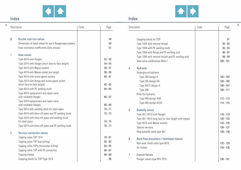
Clapping bands for TOP 91 Type 1004 with internal thread 92 – 93 Type 1004 with PE welding studs 94 – 95 Type 1004 with flange and PE welding stud 96 – 97 Type 1004 with internal thread and PE welding stud 98 – 99 Gate valve combination Multi I 100 – 101
4 Hydrants Underground hydrants Type 304 design A 102 – 103 Type 305 design AD 104 – 105 Type 304 S design A 106 – 107 Type 306 108 – 111 Pillar fire hydrants Type 494 design AUD 112 – 113 Type 495 design AFUD 114 – 115
5 Butterfly valves Type 451 / 4510 with flanges 116 – 119 Type 451 / 4510 long face-to-face length with bypass 120 – 123 Type 4510 with Novo sockets 124 – 125 Special versions 126 – 127 Ring butterfly valve type 487 128 – 130
6 Back flow preventers / Ventilation Valves Non-slam check valve type 8015 132 – 133 Air Valves 134 – 135
7 Control Valves Plunger valves type RKV 7015 136 – 141
Description Code Page
B Ductile cast iron valves 49 Dimensions of metal valves for use in flanged pipe systems 50 Flow resistance coefficients (Zeta values) 51
1 Gate valves Type 4014 with flanges 52 – 53 Type 2014 with flanges (short face-to-face length) 54 – 55 Type 4014 with Novo sockets 56 – 57 Type 4014 with Novo socket and spigot 58 – 59 Type 4014 with screw-gland sockets 60 – 61 Type 2014 with flange and screw-gland socket (short face-to-face length) 62 – 63 Type 4014 with PE welding studs 64 – 65 Type 4014 replacement and repair valve with rotatable flanges 66 – 67 Type 2014 replacement and repair valve with rotatable flanges 68 – 69 Type 3014 with welding studs for steel pipes 70 – 71 Type 4014 with blow-off pipes and PE welding studs 72 – 73 Type 3014 with blow-off pipes and welding studs for steel pipes 74 – 75 Type 3014 with blow-off pipes and PE welding studs 76 – 77
2 Service connection valves Tapping valve TOP 1014 78 – 81 Tapping valve TOP (top drilling) 82 – 83 Tapping valve TOPsi (horizontal drilling) 84 – 85 Tapping valve TOP with PE connection 86 – 87 Tapping clamps 88 – 89 Clapping bands for TOP Type 1014 90

IndexIndex1716
Description Code Page
8 Novo plug-in system Notes on Novo plug-in system 143 Type 4014 with Novo sockets 56 – 57 Type 4014 with Novo socket and spigot 58 – 59 Type 4510 with Novo sockets 124 – 125 Type 304 S design A 106 – 107 Double socket duckfoot bends 90° with Novo sockets MMN / MMNR 242 Single socket tees with spigot and socket branch B 208
Pipe section with Novo socke M 144
Spigot pipe section S 145
Novo collar U 146
Collar with Novo and screw-gland socket U 147
Spigot tee with Novo socket MI 148 – 149
All spigot tee IT 148 – 149
PE adapter piece for Novo sockets 150
9 Accessories Flap valves 152 – 153 Laying tool for TYTON® or Novo sockets 154 Hook wrench for screw-gland joints 155
Description Code Page
Operating keys for valves 156 – 157 Düker telescopic stem extension set T3 for butterfly valves 158 – 159 Düker telescopic stem extension set T3 for gate valves and tapping valves 160 – 161 Düker Quick telescopic stem extension set T3 for tapping valves type 1014 162 – 163 Surface boxes 164 – 167
C Ductile cast iron fittings and flanged pressure pipes 169
Inside and outside protection 171
10a Flanged pressure pipes Pressure pipes with cast-on flanges FFG 172 Weight table FFG 173
10b Fittings Notes 174 Marking 175
Flanged sockets E 176 – 177
Flanged sockets EU 178 – 179
Flanged spigots F 180
Collars U 181
Single socket bends 90 ° MQ 182

IndexIndex1918
Description Code Page
Double flanged duckfoot bends 90 ° N 210
Double flanged bends 45 ° FFK 45 211
Double flanged bends 30 ° FFK 30 212
Double flanged bends 22 1/2 ° FFK 22 213
Double flanged bends 11 1/4 ° FFK 11 214
All flanged tees T 215 – 220
Flanged tees with 45° flanged branch FFC 221 – 223
All flanged cross tees TT 224 – 226
Double flanged tapers concentric FFR 227 – 229
Double flanged tapers eccentric FFRe 230 – 232
Single flange bells 233
Blank flanges X 234 – 235
Blank flanges with tap hole XG 236 – 237
Pipe caps with TYTON® socket O 238 – 239
Conversion flanges 240
Description Code Page
Double socket bends 90 ° MMQ 183
Single socket bends 45 ° MK 45 184
Double socket bends 45 ° MMK 45 185
Single socket bends 30 ° MK 30 186
Double socket bends 30 ° MMK 30 187
Single socket bends 22 1/2 ° MK 22 188
Double socket bends 22 1/2 ° MMK 22 189
Single socket bends 11 1/4 ° MK 11 190
Double socket bends 11 1/4 ° MMK 11 191
Double socket tees with flanged branch MMA 192 – 197
All socket tees MMB 198 – 202
Double socket tapers MMR 203 – 205
Single socket tees with spigot and flanged branch A 206 – 207
Single socket tees with spigot and socket branch B 208
Double flanged bends 90 ° Q 209

#2120
IndexIndex
Description Code Page
11 Fittings for plastic pipelines (KS fittings) Notes 255
Flanged sockets E-KS 256
Flanged spigots F-KS 257
Flanged socket duckfoot bends 90 ° EN-KS 258
Double socket tees with flanged branch MMA-KS 259 – 260
All socket tees MMB-KS 261
Double socket tapers MMR-KS 262
Double sockets with internal thread branch MMI-KS 263 – 264
12 Sewage fittings Notes 267 Drilling saddle pieces
with 90° branch with clay pipe socket SM 90 268
with 45° branch with clay pipe socket SM 45 269
with 90° branch with spigot for ductile iron pipe or for clay pipe SI 90 270
with 45° branch with spigot for ductile iron pipe SI 45 271
Description Code Page
Flanged socket duckfoot bends 90 ° EN 241
Double socket duckfoot bends 90° with Novo sockets MMN / MMNR 242
Plugs for screw-gland and TYTON® sockets P 243
Screw rings for plugs 244
Screwed plugs for screw-gland socket PX 245
10c Special fittings 247 Single socket tees with 45° socket branch
with screw-gland sockets C
Double-flanged ball fitting 248
Flanged tee ball fitting 249
All-flanged cross tee ball fitting 250
Connection drum 251
Fittings with Puddle Flanges 252 – 253

#2322
IndexIndex
Description Code Page
D Laying and assembly instructions 283
a Laying instructions for thrust resisting joints Notes on DVGW standard GW 368 285 NOVO-SIT® 286 – 289 TYTON® SIT® 290 – 293 TYTON SIT PLUS® (TSP®) 294 – 299 Düker SMU 300 – 303 Düker SPEZIAL 304 – 307 NOVO-Grip® III 308 – 311
b Assembly instructions for socket connections 312 Bolted-gland socket connection 312 – 315
c Assembly instructions for flanges 316 Assembly instructions for pressure pipes
and fittings with flanges 316 – 318
d Assembly instructions for spot-drilling saddle pieces 319 Assembly instructions for spot-drilling saddle pieces 319 – 321
Description Code Page
TYTON® coupling MM 272
Spigot end branches 67 ° ICI 67 273
Double socket branch with TYTON® sockets, with 67°/45° branch with spigot for ductile iron pipe MMI 274
Double socket branch with TYTON® sockets, with 45° branch with clay pipe socket MMM 275
Pipe sealing cap with ventilation valve RVD 276
Manhole connection pieces with TYTON® socket SA 277
Double flanged hatchboxes 278
Double socket hatchboxes 279
Double socket tees with 45° socket branch MMC 280 – 281

AA
Joints for fittings, flanged pipes and valves made of ductile cast iron
24
EN 1563:2012
Symbol
EN-GJS-400-15EN-GJS-400-18LTEN-GJS-500-7EN-GJS-500-14
Number
5.31065.31035.32005.3109
EN 1563:1997
Number table 1
EN-JS1030EN-JS1025EN-JS1050—
Number table 3
EN-JS1072EN-JS1049EN-JS1082—
Symbol
GGG-40GGG-40.3GGG-50—
Number
0.70400.70430.7050—
Valid Standard
GJS stands for spheroidal or nodular graphite cast iron, ductile cast iron, formerly GGGGJL stands for lamellar or flake graphite cast iron, grey cast iron, formerly GG
Current and Historical Material Designationsof the cast iron qualities used by Düker
Obsolete Standards
DIN 1693-1:1973 and DIN 1693-2:1977

26 27
Aa
DN
80 100 125 150 200 250 300 350 400
450* 500 600 700 800 900100012001400
ø d1
98 118 144 170 222 274 326 378 429 480 532 635 738 842 945104812551462
ø D
141 161 188 215 271 324 381 434 489
541,5 598 707 825 9351042115013681610
t
84 88 91 94100105110110110120120120150160175185215240
Pipes
3,4 4,3 5,7 7,1 10,3 14,2 18,6 23,7 29,3 37,8 42,8 59,3 79,1102,6129,9161,3
——
Fittings
2,8 3,3 4,5 5,6 8,0 11,1 14,3 17,1 20,8 27,6 31,7 42,3 71,2 95,4150,3186,9250,0468,7
Flanged sockets
2,43,14,04,97,19,7
12,515,218,624,327,636,259,179,8
122,7152,1193,0373,0
Gasket
0,130,160,190,220,370,480,670,771,091,401,602,294,005,206,508,009,50
17,20
Dimensions in mm Weight in kg ≈ socket
Dimensions and weights
DN
40 50 65 80100125150200250300350400
450* 500*
ø d1
56 66 82 98118144170222274326378429480532
ø D
101113129146166197224280336391450503572626
t
74 77 80 84 88 91 94100106110113116164174
Pipes
— ——
3,4 4,3 5,7 7,110,314,218,623,729,3——
Fittings
1,4 1,8 2,2 2,8 3,3 4,5 5,6 8,011,114,318,622,2——
Flanged sockets
1,3 1,6 1,9 2,4 3,1 4,0 4,9 7,1 9,712,516,219,5
28,5
Dimensions in mm Weight in kg ≈ socketScrew ring
0,84 0,90 1,30 1,40 1,90 3,00 3,20 4,50 6,30 8,10 10,50 13,50 25,00 31,50
Gliding ring
0,050,060,060,070,080,100,110,170,210,300,350,400,600,87
Gasket
0,060,080,100,120,150,190,230,360,500,660,841,051,501,85
Dimensions and weights
TYTON® socket joints (TYT) acc. to DIN 28 603
Screw-gland socket joints (SMU) PN 16 1) acc. to DIN 28 601
* acc. to manufacturer’s standard 1) higher pressures on request
Socket for flanged sockets and collars Socket for pipes
Socket for fittings
Socket for fittings
* acc. to manufacturer’s standard

29
1.11.1
Aa
Bolted-gland socket joints (STB) PN 16 1) acc. to DIN 28 602
Assembly instructions see page 312 – 315
DN
100*150*200*250*300*350*400*450*500600700800900
1000120014001600
ø d1
118170222274326378429480532635738842945
1048125514621668
ø D
235 290 345 400 460 515 570 625 680 790 900101011251250145017141920
t
116118121124127129132135138143149154160165176187198
ø d2
M 20M 20M 20M 20M 20M 20M 20M 20M 20M 20M 20M 20M 20M 24M 24M 24M 24
l
80 80 80 80 90 90 90100100100110110120120130150150
n
4 8 8 8 8 12 1212 16 16 20 242424283236
Pipes
— ————26,632,245,345,361,280,0
101,0128,0162,9232,4
Flanged sockets collars
————18,722,927,638,738,752,267,985,4
108,4138,7196,5292,3319,5
Dimensions in mm Weight in kg ≈ socketBolted- gland ring
2,74,0 5,06,07,19,6
10,613,015,020,927,234,144,057,075,0
128,5142,8
Gasket
0,100,200,270,500,600,700,801,001,001,501,902,302,803,303,806,907,90
Hammer head
screws
0,24 0,24 0,24 0,24 0,27 5,5 5,5 6,0 7,7 7,7 10,0 12,0 12,0 13,0 18,0 19,5 22,0
Dimensions and weights
* acc. to manufacturer’s standard 1) higher pressures on request
Socket for pipes and fittings Socket for flanged sockets
28

3130
1.2
Ab
TYTON® socket joints with TYTON® SIT®
DN
80100125150200250300400
Number of retaining segments
4 5 5 710152030
allowable operating pressure
PFA
1616161616101010
Deflection max.
3 °3 °3 °3 °3 °3 °3 °3 °
Weight in kg ≈ TYTON® SIT®-
gasket
0,170,190,230,270,450,600,921,58
Dimensions and weights
Assembling acc. laying instruction for thrust resisting joint TYTON® SIT®, page 290 – 293
Pressure classes as per EN 545 : 2011-09
Definitions as per EN 805Allowable operating pressure PFA (bar)Allowable maximum operating pressure: PMA (bar) = 1.2 x PFAAllowable site test pressure: PEA (bar) = 1.2 x PFA + 5
Pressure class
C 100C 100C 64C 64C 64C 50C 50C 40
TYTON® socket joints with TYTON SIT PLUS®
Assembling acc. laying instruction for thrust resisting joint TYTON SIT PLUS®, page 294 – 299
DN
80 100 125 150 200 250 300 350 400 500 600
Number of retaining segments
4 5 5 710152025283542
Pressure class
C 100C 100C 100C 100 C 64 C 64 C 50 C 50 C 50 C 40 C 40
Pressure class
C 50 C 50 C 50 C 50 C 50 C 50 C 40
allowable operating pressure
PFA
16161616161616
allowable operating pressure
PFA
3232252525252525161610
Deflection max.
3 °3 °3 °3 °3 °3 °3 °3 ° 2 ° 2 ° 2 °
Weight in kg ≈ TYTON SIT PLUS®
gasket
0,140,160,200,230,450,600,951,251,502,303,00
Dimensions and weights

32 33
1.2
DN 80 up to DN 150 also available as NOVO-Grip® PVC for PVC pipes
Assembling acc. laying instruction for thrust resisting joint NOVO-Grip® III, page 308 – 311
* Note: in DN 200, it is not possible to use the standard Novo socket for NOVO-Grip®; use only items with adapted geometry and marking „for PE-HD pipes“.
DN
80100150200*
ø d1
plastic pipelines DN/OD in mm
90110160225
t
119123129138
Weight in kg ≈ assembly set
0,200,250,501,00
PFA at SDR 11 bar
16161616
PFA at SDR 17 bar
10101010
Dimensions and weights
Ab
Novo socket joints with NOVO-SIT®
Assembling acc. laying instruction for thrust resisting joint NOVO-SIT®, page 286 – 289
DN
80 100 125 150 200 250 300 350 400 450 500 600 700 800
d1
98 118 140 170 222 274 326 378 429 480 532 635 738 842
D
141 161 188 215 271 324 381 434 505 572 598 707 824 934
t
119123126129138143152154154164168168205217
Pressure class
C 100C 100C 100C 100 C 64 C 64 C 50 C 50 C 50 C 40 C 40 C 40 C 40 C 40
Pressure class
C 50 C 50 C 50 C 50 C 50 C 50 C 50
allow. o. p.PFA
25161616161616
allow. o. p.PFA
4025252525252516161616161010
Deflectionmax.
3 °3 °3 °3 °3 °3 °3 °3 °3 °3 °2 °2 °2 °1 °
NovoPre-
chamber
1,2 1,4 1,8 2,1 3,1 4,8 5,7 6,4 8,3 9,512,016,629,536,6
NOVO-SIT®
ring
0,150,200,250,350,650,801,001,301,502,002,503,003,503,60
Dimensions in mm Weight in kg ≈
Dimensions and weights
Number of
locking segments
5571013182222252835456270
Restrained socket joints for plastic pipelines with NOVO-Grip® III
Locking ringCompression ring
Gasket (GKS)
Note: The Novo socket does not change the standardised length of fittings and valves.
NOVO pre-chamber
3534
1.2
Ab
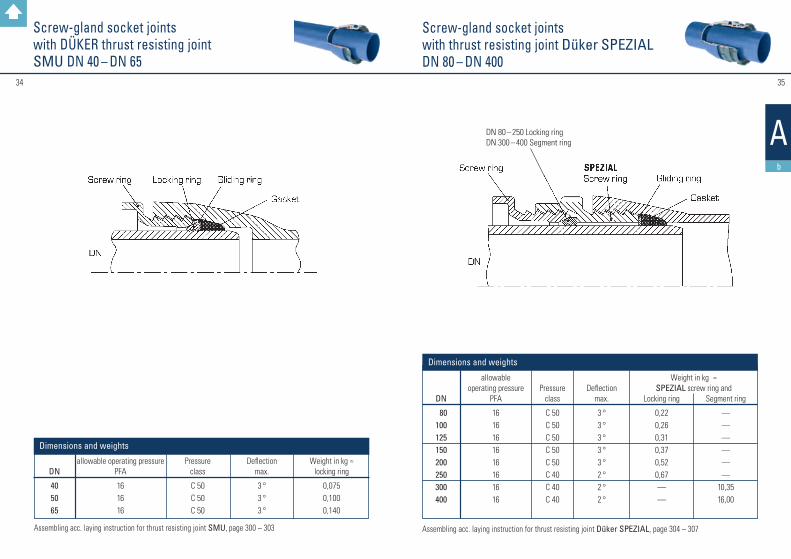
Screw-gland socket jointswith DÜKER thrust resisting joint SMU DN 40 – DN 65
Assembling acc. laying instruction for thrust resisting joint SMU, page 300 – 303
DN
40 5065
allowable operating pressurePFA
161616
Deflectionmax.
3 °3 °3 °
Pressureclass
C 50C 50C 50
Weight in kg ≈ locking ring
0,0750,1000,140
Dimensions and weights
Screw-gland socket joints with thrust resisting joint Düker SPEZIALDN 80 – DN 400
Assembling acc. laying instruction for thrust resisting joint Düker SPEZIAL, page 304 – 307
DN 80 – 250 Locking ringDN 300 – 400 Segment ring
DN
80100125150200250300400
allowable operating pressure
PFA
1616161616161616
Pressure class
C 50C 50C 50C 50C 50C 40C 40C 40
Deflectionmax.
3 °3 °3 °3 °3 °2 °2 °2 °
Locking ring
0,220,260,310,370,520,67——
Weight in kg ≈ SPEZIAL screw ring and
Dimensions and weights
Segment ring
——————
10,3516,00
3736
1.3
Ac
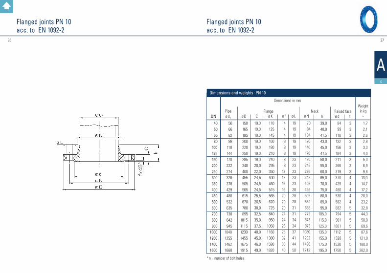
Flanged joints PN 10 acc. to EN 1092-2
Flanged joints PN 10 acc. to EN 1092-2
* n = number of bolt holes
DN
40 50 65 80 100 125 150 200 250 300 350 400 450 500 600 700 800 9001000120014001600
Pipe ø d1
56 66 82 98 118 144 170 222 274 326 378 429 480 532 635 738 842 9451048125514621668
ø D
150 165 185 200 220 250 285 340 400 455 505 565 615 670 780 895101511151230145516751915
C
19,019,019,019,019,019,019,020,022,024,524,524,525,526,530,032,535,037,540,045,046,049,0
ø K
110 125 145 160 180 210 240 295 350 400 460 515 565 620 725 840 95010501160138015901820
n*
4 4 4 8 8 8 8 81212161620202024242828323640
ø L
19191919191923232323232828283131343437414450
ø N
70 84 104 120 140 170 190 246 298 348 408 456 502 559 658 772 876 9761080129214961712
Dimensions in mm h
39,0 40,0 41,5 43,0 45,0 47,5 50,0 55,0 60,0 65,0 70,0 75,0 80,0 85,0 95,0105,0115,0125,0135,0155,0175,0195,0
ø d
84 99 118 132 156 184 211 266 319 370 429 480 530 582 682 794 901 10011112 132815301750
f
3333333334444455555555
Weight in kg
≈
1,7 2,1 2,6 2,8 3,3 4,0 5,0 6,9 9,8 13,0 14,7 17,2 20,0 23,2 32,8 44,3 58,8 69,6 87,6121,0180,0262,0
Flange Neck Raised face
Dimensions and weights PN 10

3938
1.3
Ac
Flanged joints PN 16acc. to EN 1092-2
Flanged joints PN 16acc. to EN 1092-2
* n = number of bolt holes
DN
40 50 65 80 100 125 150 200 250 300 350 400 450 500 600 700 800 9001000120014001600
Pipe ø d1
56 66 82 98 118 144 170 222 274 326 378 429 480 532 635 738 842 9451048125514621668
ø D
150 165 185 200 220 250 285 340 400 455 520 580 640 715 840 910102511251255148516851930
C
19,0 19,0 19,0 19,0 19,0 19,019,020,022,0 24,5 26,528,030,031,536,039,543,046,550,057,060,065,0
ø K
110 125 145 160 180 210 240 295 355 410 470 525 585 650 770 840 95010501170139015901820
n*
4 4 4 8 8 8 8121212161620202024242828323640
ø L
19191919191923232828283131343737414144505057
ø N
70 84 104 120 140 170 190 246 296 350 410 458 516 576 690 760 862 9621076128214821696
Dimensions in mm h
39,0 40,0 41,5 43,0 45,0 47,5 50,0 55,0 60,0 65,0 70,0 75,0 80,0 85,0 95,0 105,0 115,0 125,0 135,0 155,0175,0195,0
ø d
84 99 118 132 156 184 211 266 319 370 429 480 548 609 720 794 90110011112132815301750
f
3333333334444455555555
Weight in kg
≈
1,7 2,1 2,6 2,8 3,3 4,0 5,0 6,7 9,4 12,6 17,5 22,1 30,2 37,4 57,6 57,4 76,8 91,4127,0185,0213,0315,0
Flange Neck Raised face
Dimensions and weights PN 16

40 41
1.3
Ac
Flanged joints PN 25acc. to EN 1092-2
Flanged joints PN 25acc. to EN 1092-2
* n = number of bolt holes
DN
40 50 65 80 100 125 150 200 250 300 350 400 450 500 600 700 800 9001000120014001600
Pipe ø d1
56 66 82 98 118 144 170 222 274 326 378 429 480 532 635 738 842 9451048125514621668
ø D
150 165 185 200 235 270 300 360 425 485 555 620 670 730 845 960108511851320153017551975
C
19,019,019,019,019,019,020,022,024,527,530,032,034,536,542,046,551,055,560,069,074,081,0
ø K
110 125 145 160 190 220 250 310 370 430 490 550 600 660 770 875 99010901210142016401860
n*
4 4 8 8 8 8 8121216161620202024242828323640
ø L
19191919 23 28 28 28 31 31 34 37 37 37 41 44 50 50 57 576262
ø N
70 84 104 120 142 162 192 252 304 364 418 472 520 580 684 780 882 9821086129615081726
Dimensions in mm h
39 4041,5 43 4547,5 50 55 60 65 70 75 80 85 95105115125135155175195
ø d
84 99 118 132 156 184 211 274 330 389 448 503 548 609 720 820 92810281140135015601780
f
3333333334444455555555
Weight in kg
≈
1,7 2,1 2,4 2,8 3,8 4,7 6,0 8,7 13,0 17,7 25,4 33,2 40,2 47,2 71,5 90,0123,0149,0201,0 285,0357,0484,0
Flange Neck Raised face
Dimensions and weights PN 25

4342
1.3
Ac
Flanged joints PN 40acc. to EN 1092-2
DN
40 50 65 80 100 125 150 200 250 300 350 400 450 500 600
Pipe ø d1
56 66 82 98 118 144 170 222 274 326 378 429 480 532 635
ø D
150165185200235270300375450515580660685755890
C
19,019,019,019,019,023,526,030,034,539,544,048,049,052,058,0
ø K
110125145160190220250320385450510585610670795
n*
4 4 8 8 8 8 81212161616202020
ø L
191919192328283134343741414450
ø N
70 84104120142162192254312378432498522576686
Dimensions in mm h
39,0 40,0 41,5 43,0 45,0 47,5 50,0 55,0 60,0 65,0 70,0 75,0 80,0 85,0 95,0
ø d
84 99 118 132 156 184 211 284 345 409 465 535 560 615 735
f
333333333444445
Weight in kg
≈
1,7 2,1 2,4 2,8 3,8 5,9 8,0 14,0 23,5 33,5 43,0 62,0 57,0 82,0124,0
Flange Neck Raised face
Dimensions and weights PN 40
Flanged joints PN 40acc. to EN 1092-2
* n = number of bolt holes

4544
1.3
Ac
Hexagon head screws for flanges PN 25 and PN 40 acc. to EN 1092-2
Hexagon head screws for flanges PN 10 and PN 16 acc. to EN 1092-2
l1* = Screw length for connection with one washer l2** = Screw length for connection with two washersSpecial stipulations: M16 x 80: Thread length min. 44 mm, M20 x 90: Thread length min. 52 mm, M24 x 100/110: Thread length min. 60 mm; l1* = Screw length for connection with one washer l2** = Screw length for connection with two washers
qty per joint
4 4 8 8 8 8 81212161616202020
DN
40 50 65 80 100 125 150 200 250 300 350 400 450 500 600 700 800 90010001200
ø d1
M 16M 16M 16M 16M 20M 24M 24M 24M 27M 27M 30M 33M 33M 33M 36M 39M 45M 45M 52M 52
l1*
80 80 80 80 80 90 90 90 100 110120 130 130 140150170180190210230
l2**
80 80 80 80 90 90 90
100 110 110120 130 130 140150170190200210230
qty per joint
4 4 8 8 8 8 812121616162020202424282832
Dimensions in mm Dimensions in mm
ø d1
M 16M 16M 16M 16M 20M 24M 24M 27M 30M 30M 33M 36M 36M 39M 45
l1*
80 80 80 80 80
100100110120140 150160160170190
l2**
80 80 80 80 90
100110120130140 150170170180200
PN 40PN 25
Not specified in EN 1092-2
DN
40 50 65 80 100 125 150 200 250 300 350 400 450 500 600 700 800 9001000120014001600
ø d1
M 16M 16M 16M 16M 16M 16M 20M 20M 20M 20M 20M 24M 24M 24M 27M 27M 30M 30M 33M 36M 39M 45
l1*
80 80 80 80 80 80 80 80 90 90 90
100 100 100 110 120130130
140160170180
l2**
80 80 80 80 80 80 90 90 90 90 90
100 110 110 120 120130140 150160170190
qty per joint
4 4 4 8 8 8 8 81212161620202024242828323640
Dimensions in mm Dimensions in mm
ø d1
M 16M 16M 16M 16M 16M 16M 20M 20M 24M 24M 24M 27M 27M 30M 33M 33M 36M 36M 39M 45M 45M 52
l1*
80 80 80 80 80 80 80 80 90
100 100 110 110120 130 140150160170190200220
l2**
80 80 80 80 80 80 90 90
100 100 110 110 120120 140 150160160180200210230
qty per joint
4 4 4 8 8 8 8121212161620202024242828323640
PN 16PN 10

4746
1.3
Ac
Arrangement of bolt holesFlat gaskets for Flanges acc. to EN 1514-1, type IBC
Dimensions for gaskets with steel inlay.The number of bolt holes is always divisible by 4.The bolt holes are arranged symmetrically to the two main axes, but not on them.
DN
40 50 65 80 100 125 150 200 250 300 350 400 500 600 700 800 9001000120014001600
ø D 1
49 61 77 90 115 141 169 220 274 325 368 420 520 620 720 820 9201020122014201620
PN 10
328 378 438 490 595 695 810 91510151120
15451770
ø D 2
92 107 127 142 162 192 218 273
1340
PN 16
330 385 445 497 618 735 805 91010051110
15401760
s
444455566677778888888
DN
40 50 65 80 100 125 150 200 250 300 350 400 450 500 600 700 800 9001000120014001600
EN 1092-2PN 10
4 4 4 8 8 8 8 81212161620202024242828323640
EN 1092-2PN 16
4 4 4 8 8 8 8121212161620202024242828323640
EN 1092-2PN 25
4 4 8 8 8 8 812121616162020202424282832——
EN 1092-2PN 40
4 4 8 8 8 8 81212161616202020———————
Dimensions and weights
Number of bolts

48
BB
Ductile cast iron valves
Back to summary

#5150
B
Face-to-face and centre-to-face dimensions of metal valves for use in flanged pipe systems
Flow resistance coefficients as per EN 736-3(Zeta values)
Excerpts from EN 558Table 2 – Face-to-face lengths of the basic series
for Düker valves measured in fully open position
* on request
40506580
100125150200250300350400450500600700800900
100012001400160018002000
200230340310350400480600730850980
11001200125014501650185020502250
—————
260300340380430500550650775900
10251150127514001600
—————————
240250270280300325350400450500550600650700800900100011001200
—————
106108112114127140140152165178190216222229267292318330410470530600670760
140150170180190200210230250270290310330350390430470510550630710790870950
2402502903103504004505506507508509501050115013501550175019502150
—————
1802002402603003504005006007008009001000110013001500170019002100
—————
3343466464707689114114127140152152178229241241300350390440490540
3343464652565660687878102114127154165190203216254279318356406
basic series as per EN 558
1 2 13 14 15 16 20 26 48
former type series as per German DIN 3202
F1 F2 F16 F4 F5 K3 K1 F7 F6
DN
4050658010012515020025030035040050060070080090010001200
0,1230,1770,1060,0990,0980,0870,0840,0820,0800,076
—————————
—— — —
0,80—0,750,560,500,400,380,350,250,25—————
——————
1,40
*****
———————
Gate valves 4014 and 2014
series
Butterfly valvetype 4510
Butterfly valvetype 451
Non-slam check valve
type 8015
Plunger valvetype 7015(seat ring)
———— — — — — — — — — — —
0,210,180,170,160,15
———
0,600,690,690,790,770,65
*—————————

#5352
3.1
B1
Design features: Resilient-seated gate valve, with smooth passage, internal stem thread, non-rising stem; edge protection for bonnet and body, countersunk and sealed A2 screws between body and bonnet, medium-free stem bearingsealing wedge entirely vulcanisedflange connection dimensions: as per EN 1092–2face-to-face length: as per EN 558, basic series 15for potable water, sewerage, gas or biogas
Operation: • with hand wheel• with stem extension (for underground installation) – connection as per GW 336-1• with electrical actuator (on request)
Materials: ductile cast iron EN-GJS-500-7 as per EN 1563stem: chromium steel X20Cr13 (for biogas and sewerage: 1.4571)stem nut: special brass (for biogas and sewerage: aluminium bronze)rubber parts made of high-quality elastomer:sealing wedge for water: EPDMsealing wedge for gas, biogas and sewerage: NBR
Surface protection: • inside and outside Düker etec enamel as per EN ISO 11177, DEV guideline for soil class III (for water)• inside and outside Düker etec enamel as per EN ISO 11177, DEV guideline for soil class III (for sewerage)• inside and outside epoxy finish blue RAL 5005 as per GSK guidelines (for water)• inside and outside epoxy finish blue RAL 5005 as per GSK guidelines (for sewerage)• inside and outside epoxy finish yellow RAL 1023 as per GSK guidelines (for gas)• inside and outside epoxy finish yellow RAL 1023 as per GSK guidelines (for biogas)
PG 3 5 bar
0,5 a. 6
PG 3 16 bar
0,5 a. 17,6
PG 2
0,5
17,6 11
17,6 11
24 15 24 15 24 24
Test pressure in bar test medium water test medium air body seat seat seat seat
Field of application: potable water up to 60 °C; sewerage; gas as per G 260/I; biogas as per medium analysis
Nominal diameter
DN
40-300
200-300 50-300
200-300 40-300 50-300
Nominal pressure
PN
16 10 16 10
0,5/16 5
Field of
application
potable water potable water
sewerage sewerage
gas biogas
Gate valves type 4014with flanges PN 10 / 16
DN
40506580
100125150200200250250300300
PN
16161616161616101610161016
FTF
240250270280300325350400400450450500500
ø K
110125145160180210240295295350355400410
h1
207233270270295330 373462462648648723723
ø D
150165185200220250285340340400400455455
a
141417171919192424 27 272727
Weight in kg ≈
12,514,718,818,424,028,737,758,157,6113,6113,0161,0160,0
Number
of screws
4 4 4 8 8 8 8 8 1212121212
ø L
19191919191923232323282328
Dimensions and weights ( Dimensions in mm )

#5554
B1
Design features: Resilient-seated gate valve, with smooth passage, internal stem thread, non-rising stem; edge protection for bonnet and body, countersunk and sealed A2 screws between body and bonnet, medium-free stem bearingsealing wedge entirely vulcanised flange connection dimensions: as per EN 1092–2face-to-face length: as per EN 558, basic series 14for potable water, sewerage, gas or biogas
Operation: • with hand wheel• with stem extension (for underground installation) – connection as per GW 336-1• with electrical actuator (on request)
Materials: ductile cast iron EN-GJS-500-7 as per EN 1563stem: chromium steel X20Cr13 (for biogas and sewerage: 1.4571)stem nut: special brass (for biogas and sewerage: aluminium bronze)rubber parts made of high-quality elastomer:sealing wedge for water: EPDMsealing wedge for gas, biogas and sewerage: NBR
Surface protection: • inside and outside Düker etec enamel as per EN ISO 11177, DEV guideline for soil class III (for water)• inside and outside Düker etec enamel as per EN ISO 11177, DEV guideline for soil class III (for sewerage)• inside and outside epoxy finish blue RAL 5005 as per GSK guidelines (for water)• inside and outside epoxy finish blue RAL 5005 as per GSK guidelines (for sewerage)• inside and outside epoxy finish yellow RAL 1023 as per GSK guidelines (for gas)• inside and outside epoxy finish yellow RAL 1023 as per GSK guidelines (for biogas)
PG 3 5 bar
0,5 a. 6
PG 3 16 bar
0,5 a. 17,6
PG 2
0,5
17,6 11
17,6 11
24 15 24 15 24 24
Test pressure in bar test medium water test medium air body seat seat seat seat
Field of application: potable water up to 60 °C; sewerage; gas as per G 260/I; biogas as per medium analysis
Nominal diameter
DN
40-300
200-300 50-300
200-300 40-300 50-300
Nominal pressure
PN
16 10 16 10
0,5/16 5
Field of
application
potable water potable water
sewerage sewerage
gas biogas
Gate valves type 2014 (short face-to-face length)with flanges PN 10 / 16
DN
40506580
100125150200200250250300300
PN
16161616161616101610161016
FTF
140150170180190200210230230250250270270
ø K
110125145160180210240295295350355400410
h1
207233270270295330 373462462648648723723
ø D
150165185200220250285340340400400455455
a
141417171919192424 27 272727
Weight in kg ≈
11,213,317,018,721,925,533,151,451,0104,4104,0146,7146,0
Number
of screws
4 4 4 8 8 8 8 8 1212121212
ø L
19191919191923232323282328
Dimensions and weights ( Dimensions in mm )

#5756
3.1
B1
Design features: Resilient-seated gate valve, with smooth passage, internal stem thread, non-rising stem; edge protection for bonnet and body, countersunk and sealed A2 screws between body and bonnet, medium-free stem bearingsealing wedge entirely vulcanisedconnection: as per DIN 28603 (TYTON® with pre-chamber)face-to-face length: as per EN 558, basic series 13for potable water, waste water on request
Operation: • with hand wheel• with stem extension (for underground installation) – connection as per GW 336-1• with electrical actuator (on request)
Materials: ductile cast iron EN-GJS-500-7 as per EN 1563Stem: chromium steel X20Cr13stem nut: special brassrubber parts made of high-quality elastomer:sealing wedge for water: EPDM
Surface protection: • inside and outside Düker etec enamel as per EN ISO 11177, DEV guideline for soil class III (for water)• inside and outside epoxy finish blue RAL 5005 as per GSK guidelines (for water)
Test pressure in bartest medium water
body seat 24 17,6
Field of application: potable water up to 60 °C
Nominal diameter DN
80-300
Nominal
pressure PN
16
Field of
application
potable water
Gate valves type 4014 plug-in socket gate valves with Novo sockets PN 16
DN
80100125150200250300
PN
16161616161616
h1
270295330373462648723
Weight in kg ≈
19,923,427,734,653,6
107,0 151,0
Dimensions and weights ( Dimensions in mm )
ETE
114127140140152165178
a
17191919242727

#5958
3.1
B1
Design features: Resilient-seated gate valve, with smooth passage, internal stem thread, non-rising stem; edge protection for bonnet and body, countersunk and sealed A2 screws between body and bonnet, medium-free stem bearing sealing wedge entirely vulcanisedconnection: as per DIN 28603 (TYTON® with pre-chamber)face-to-face length: as per EN 558, basic series 13for potable water
Operation: • with hand wheel • with stem extension (for underground installation) – connection as per GW 336-1 • with electrical actuator (on request)
Materials: ductile cast iron EN-GJS-500-7 as per EN 1563 stem: chromium steel X20Cr13 stem nut: special brass rubber parts made of high-quality elastomer: sealing wedge for water: EPDM
Surface protection: • inside and outside Düker etec enamel as per EN ISO 11177, DEV guideline for
soil class III (for water) • inside and outside epoxy finish blue RAL 5005 as per GSK guidelines (for water)
Gate valves type 4014 Single socket gate valves with Novo sockets and spigot end PN 16
Test pressure in bartest medium water
body seat 24 17,6
Field of application: potable water up to 60 °C
Nominal diameter DN
80-300
Nominal
pressure PN
16
Field of
application
potable water
DN
80100125150200250300
PN
16161616161616
ø D
97117143169221274326
h1
270295330373462648723
ø D1
141161188215271324381
Weightin kg ≈
19,121,927,033,752,6109,0120,0
Dimensions and weights ( Dimensions in mm )
L1
235235290290310310310
L
410422485490525535550
a
17191919242727

#6160
3.1
B1
Design features: Resilient-seated gate valve, with smooth passage, internal stem thread, non-rising stem; edge protection for bonnet and body, countersunk and sealed A2 screws between body and bonnet, medium-free stem bearing sealing wedge entirely vulcanisedconnection: as per DIN 28601face-to-face length: as per EN 558, basic series 13 for potable water
Operation: • with hand wheel • with stem extension (for underground installation) – connection as per GW 336-1 • with electrical actuator (on request)
Materials: ductile cast iron EN-GJS-500-7 as per EN 1563stem: chromium steel X20Cr13stem nut: special brassrubber parts made of high-quality elastomer:sealing wedge for water: EPDM
Surface protection: • inside and outside Düker etec enamel as per EN ISO 11177, DEV guideline for soil class III (for water)• inside and outside epoxy finish blue RAL 5005 as per GSK guidelines (for water)
Gate valves type 4014 socket gate valves with screw-gland sockets PN 16
Test pressure in bartest medium water
body seat 24 17,6
Field of application: potable water up to 60 °C
Nominal diameter DN
40-200
Nominal
pressure PN
16
Field of
application
potable water
DN
40 50 80100125150200
ETE
106108114127140140152
L
240250282303322328352
h1
207233270295330373462
Weight in kg 1)
10,011,818,921,425,733,150,2
Dimensions and weights ( Dimensions in mm )
a
14141719191924
PN
16161616161616
1) without screw ring

#6362
3.1
B1
Gate valves type 2014 (short face-to-face length) flanged socket gate valves with socket and flange PN 16
Design features: Resilient-seated gate valve, with smooth passage, internal stem thread, non-rising stem; edge protection for bonnet and body, countersunk and sealed A2 screws between body and bonnet, medium-free stem bearingsealing wedge entirely vulcanised connection: screw-gland socket as per DIN 28601 or socket as per DIN 28603 (TYTON®, Novo); flange as per EN 1092-2Face-to-face length: as per EN 558, basic series 13/14for potable water
Operation: • with hand wheel• with stem extension (for underground installation) – connection as per GW 336-1• with electrical actuator (on request)
Materials: ductile cast iron EN-GJS-500-7 as per EN 1563stem: chromium steel X20Cr13stem nut: special brassrubber parts made of high-quality elastomer:sealing wedge for water: EPDM
Surface protection: • inside and outside Düker etec enamel as per EN ISO 11177, DEV guideline for soil class III (for water)• inside and outside epoxy finish blue RAL 5005 as per GSK guidelines (for water)
Test pressure in bartest medium water
body seat 24 17,6
Field of application: potable water up to 60 °C
Nominal diameter DN
80-200
Nominal
pressure PN
16
Field of
application
potable water
DN
80100125150200200
PN
161616161016
FTE
150160170175190190
ø K
160180210240295295
h1
270295330373462462
ø D
200220250285340340
a
171919192424
Weight in kg ≈
18,722,726,733,652,652,3
Number
of screws
8 8 8 8 812
ø L
191919232323
Dimensions and weights ( Dimensions in mm )

#6564
3.1
B1
Gate valves type 4014 with welding studs PE PN 10/16
Design features: Resilient-seated gate valve, with smooth passage, internal stem thread, non-rising stem; edge protection for bonnet and body, countersunk and sealed A2 screws between body and bonnet, medium-free stem bearingsealing wedge entirely vulcanised connection: pre-installed PE-HD welding studs as per DVGW G 5600-1 with connection dimensions as per DIN 8074/8075. Suitable for electro-welding and butt-weldingface-to-face length: as per EN 558, basic series 13for potable water, gas or biogas
Operation: • with hand wheel• with stem extension (for underground installation) – connection as per GW 336-1
Materials: ductile cast iron EN-GJS-500-7 as per EN 1563stem: chromium steel X20Cr13 (for biogas: 1.4571)stem nut: special brass (for biogas: aluminium bronze)rubber parts made of high-quality elastomer:sealing wedge for water: EPDMsealing wedge for gas and biogas: NBR
Surface protection: • inside and outside Düker etec enamel as per EN ISO 11177, DEV guideline for soil class III (for water)• inside and outside epoxy finish yellow RAL 1023 as per GSK guidelines (for gas) • inside and outside epoxy finish yellow RAL 1023 as per GSK guidelines (for biogas)
Test pressure in bar test medium water test medium air body seat seat PG 3 5 bar or 10 bar 24 17,6
15 11 24 0,5 and 6 24 0,5 and 11 24 0,5 and 6
Field of application: potable water up to 40 °C; gas as per G 260/I; biogas as per medium analysis
Nominal diameter DN
80-200 80-200 80-200 80-200 80-200
Nominal
pressure PN
16 10 5
10 5
SDR
11 17
11/17 11
11/17
Field of
application
potable water potable water
gas gas
biogas
DN
80100100125125150150200200200
PN
16161616161616161616
ø D
90110125125140160180200225250
Weightin kg ≈
24,929,430,437,737,752,152,183,684,689,6
Dimensions and weights ( Dimensions in mm )
L
680710736790790840860970954
1185
h1
270295295330330373373462462462
ETE
120134136152152162160170170175
a
17191919191919242424
L2 min.
175180190203203220231265257373

#6766
B1
Replacement and repair valves type 4014 with rotatable flanges PN 10/16
Design features: Resilient-seated gate valve, with smooth passage, internal stem thread, non-rising stem; edge protec-tion for bonnet and body, countersunk and sealed A2 screws between body and bonnet, medium-free stem bearing sealing wedge entirely vulcanised connection: thrust-resistant rotatable flanges with integrated sealing, connection dimensions as per EN 1092-2face-to-face length: as per EN 558, basic series 15for potable water
Operation: • with hand wheel• with stem extension (for underground installation) – connection as per GW 336-1• with electrical actuator (on request)
Materials: ductile cast iron EN-GJS-500-7 as per EN 1563stem: chromium steel X20Cr13stem nut: special brassrubber parts made of high-quality elastomer:sealing wedge for water: EPDM
Surface protection:• inside and outside Düker etec enamel as per EN ISO 11177, DEV guideline for soil class III (for water)
Test pressure in bartest medium water
body seat 24 17,6 15 11
Field of application: potable water up to 60 °C
Nominal diameter DN
80-200 200
Nominal
pressure PN
16 10
Field of
application
potable water potable water
DN
80100125150200200
PN
161616161016
FTF
280300325350400400
ø K
160180210240295295
h1
270295330373462462
ø D
200220250285340340
a
171919192424
Weight in kg ≈
21,425,431,241,162,662,1
Number
of screws
8 8 8 8 812
ø L
191919232323
Dimensions and weights ( Dimensions in mm )

#6968
3.1
B1
Design features: Resilient-seated gate valve, with smooth passage, internal stem thread, non-rising stem; edge protec-tion for bonnet and body, countersunk and sealed A2 screws between body and bonnet, medium-free stem bearing sealing wedge entirely vulcanised connection: thrust-resistant rotatable flanges with integrated sealing, connection dimensions as per EN 1092-2face-to-face length: as per EN 558, basic series 14for potable water
Operation: • with hand wheel• with stem extension (for underground installation) – connection as per GW 336-1• with electrical actuator (on request)
Materials: ductile cast iron EN-GJS-500-7 as per EN 1563stem: chromium steel X20Cr13stem nut: special brassrubber parts made of high-quality elastomer:sealing wedge for water: EPDM
Surface protection:• inside and outside Düker etec enamel as per EN ISO 11177, DEV guideline for soil class III (for water)
Replacement and repair valves type 2014 with rotatable flanges PN 10/16
Test pressure in bartest medium water
body seat 24 17,6 15 11
Field of application: potable water up to 60 °C
Nominal diameter DN
80-200 200
Nominal
pressure PN
16 10
Field of
application
potable water potable water
DN
80100125150200200
PN
161616161016
FTF
180190200210230230
ø K
160180210240295295
h1
270295330373462462
ø D
200220250285340340
a
171919192424
Weight in kg ≈
19,920,425,733,151,651,6
Number
of screws
8 8 8 8 812
ø L
191919232323
Dimensions and weights ( Dimensions in mm )

#7170
3.1
B1
Gate valves type 3014with welding studs for steel pipes PN 16
Design features: Resilient-seated gate valve, with smooth passage, internal stem thread, non-rising stem; countersunk and sealed A2 screws between body and bonnet, medium-free stem bearingsealing wedge entirely vulcanised connection: welding studs as per EN 12627 for steel pipesface-to-face length: as per EN 12982, basic series 15for gas
Operation: • with hand wheel• with stem extension (for underground installation) – connection as per GW 336-1
Materials: body ductile cast iron EN-GJS-400-18 as per EN 1563bonnet, sealing wedge ductile cast iron EN-GJS-500-7 as per EN 1563stem: chromium steel X20Cr13studs for welding St 35.8 / P235GHstem nut: special brass rubber parts made of high-quality elastomer:sealing wedge for gas: NBR
Surface protection:• inside Düker enamel blue• outside polyurethane as per DIN 30677-2, tested 15 KV
Nominal
diameter DN
50-300
Test pressure in bar test medium water test medium air body seat PG 3 16 bar 24 0,5 and 17,6
Field of application: gas as per G 260/I
Nominal pressure PN
16
Field of
application
gas
DN
50 80100150200250300
PN
16161616161616
ø D
60,3 88,9114,3168,3219,1273,1323,9
Weightin kg ≈
10,512,715,924,840,086,5130,0
Dimensions and weights ( Dimensions in mm )
h1
233270295373462648723
L
420280300350400450500
S
4,55,65,66,37,16,37,1
a
14171919242727
#7372
3.1
B1
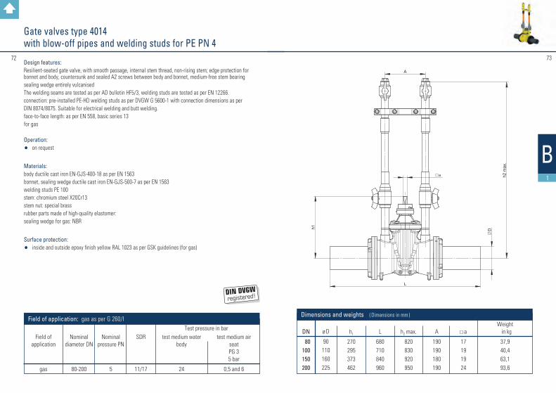
Gate valves type 4014 with blow-off pipes and welding studs for PE PN 4
Design features: Resilient-seated gate valve, with smooth passage, internal stem thread, non-rising stem; edge protection for bonnet and body, countersunk and sealed A2 screws between body and bonnet, medium-free stem bearingsealing wedge entirely vulcanisedThe welding seams are tested as per AD bulletin HF5/3, welding studs are tested as per EN 12266.connection: pre-installed PE-HD welding studs as per DVGW G 5600-1 with connection dimensions as perDIN 8074/8075. Suitable for electrical welding and butt welding.face-to-face length: as per EN 558, basic series 13for gas
Operation: • on request
Materials: body ductile cast iron EN-GJS-400-18 as per EN 1563bonnet, sealing wedge ductile cast iron EN-GJS-500-7 as per EN 1563welding studs PE 100stem: chromium steel X20Cr13 stem nut: special brass rubber parts made of high-quality elastomer:sealing wedge for gas: NBR
Surface protection:• inside and outside epoxy finish yellow RAL 1023 as per GSK guidelines (for gas)
test medium air
seat PG 3 5 bar
0,5 and 6
Test pressure in bar
Field of application: gas as per G 260/I
Nominal
diameter DN
80-200
Nominal
pressure PN
5
SDR
11/17
test medium water
body
24
Field of
application
gas
DN
80100150200
h2 max.
820830920950
A
190190180190
L
680710840960
h1
270295373462
Weight in kg 37,940,463,193,6
Dimensions and weights ( Dimensions in mm )
a
17191924
ø D
90110160225

#7574
3.1
B1
Gate valves type 3014 with blow-off pipes and welding studs for steel pipes PN 4
Design features: Resilient-seated gate valve, with smooth passage, internal stem thread, non-rising stem; countersunk and sealed A2 screws between body and bonnet, medium-free stem bearingsealing wedge entirely vulcanisedAll welding seams are tested as per AD bulletin HP5/3, all welding studs are tested as per EN 12266.connection: welding studs as per EN 12627 for steel pipesface-to-face length: as per EN 12982, basic series 15for gas
Operation: • on request
Materials: body ductile cast iron EN-GJS-400-18 as per EN 1563bonnet, sealing wedge ductile cast iron EN-GJS-500-7 as per EN 1563 stem: chromium steel X20Cr13studs for welding St 35.8 / P235GHsteam nut: special brass rubber parts made of high-quality elastomer:sealing wedge for gas: NBR
Surface protection:• inside Düker enamel blue• outside polyurethane as per DIN 30677-2, tested 15 KV
Nominal
diameter DN
80-300
Test pressure in bar test medium water test medium air body seat PG 3 5 bar 24 0,5 and 6
Field of application: gas as per G 260/I
Nominal pressure PN
5
Field of
application
gas
DN
80100150200250300
h2 max.
111011401250132013801410
A
180180224224224224
L
660680730780
10501085
h1
270295373462648723
Dimensions and weights ( Dimensions in mm )
a
171919242727
ø D
88,9114,3168,3219,1273,1323,9
Weight in kg 28,932,462,178,6120,0138,0

#7776
3.1
B1
Gate valves type 3014 with blow-off pipes and welding studs for PE PN 4
Design features: Resilient-seated gate valve, with smooth passage, internal stem thread, non-rising stem; countersunk and sealed A2 screws between body and bonnet, medium-free stem bearingsealing wedge entirely vulcanisedAll welding seams are tested as per AD bulletin HP5/3, all welding studs are tested as per EN 12266.connection: pre-installed PE-HD welding studs as per DVGW G 5600-1 with connection dimensions as per DIN 8074/8075. Suitable for electrical welding and butt welding. Double socket welding length. face-to-face length: as per EN 12982, basic series 15for gas
Operation: • on request
Materials: body ductile cast iron EN-GJS-400-18 as per EN 1563bonnet, sealing wedge ductile cast iron EN-GJS-500-7 as per EN 1563welding studs PE 100stem: chromium steel X20Cr13 steam nut: special brass rubber parts made of high-quality elastomer:sealing wedge for gas: NBR
Surface protection:• inside Düker enamel blue• outside polyurethane as per DIN 30677-2, tested 15 KV
test medium air
seat PG 3 5 bar
0,5 and 6
Test pressure in bar
Field of application: gas as per G 260/I
Nominal
diameter DN
100-200
Nominal
pressure PN
5
SDR
11/17
test medium water
body
24
Field of
application
gas
DN
100150150200
h2 max.
1140125012501320
A
180224224224
L
1560172017401920
h1
295373373462
Weight in kg 40,471,179,1116,6
Dimensions and weights ( Dimensions in mm )
a
19191924
ø D
110160180225

#7978
B2
a
title
ofdata transfer 11
Düker GmbH & Co. KGaAdate scale different from original
DN
80 – 400
Dimensions and weights ( Dimensions in mm )
I1
164
I2
86
b
308
h1
76
h2
106
G
1 1/2
„a
12
Tapping Valve TOP-Fix Type 1014with internal pipe thread 1 ½“, PN 16
Design features: compact tapping valve, low-built design, with inferior flow resistance. Installation possible on pipes of all diameters from DN 80 up to DN 400. Suitable for drilling under pressure. Suitable for pipes made of ductile iron, steel and asbestos cement.
Technical features: No additional support valves are required for tapping under pressure. The sealing is protected from damage caused by the drilling process. Only one turn is required for closing the valve up to the end stop. No residual water.maximum drilling diameter: 38 mmstem square ends: 12mm
Outlet: internal pipe thread as per EN 10226-1: Rp 1 1/2“
Clapping band types: see page 90
Materials: top and bottom parts of the body: ductile cast iron EN-GJS-500-7 as per EN 1563stem: GX3CrNiMo13-4serrated disk: X6Cr17, rubberisedsealings: high-quality elastomer (EPDM) as per DVGW W270 elastomer guideline
Surface protection:ductile iron parts inside and outside Düker etec enamel as per EN ISO 11177, DEV guideline for soil class III (for water)
Weight in kg ≈
6,7
Test pressure in bartest medium water
body seat 24 17,6
Field of application: potable water up to 60 °C
Nominal pressure PN
16
Field of application
potable water

#8180
B2
a
title
ofdata transfer 11
Düker GmbH & Co. KGaAdate scale different from original
DN
25324050
Dimensions and weights ( Dimensions in mm )
ø D
32405063
I1
164164164164
I2
86868686
b
308308308308
h1
106106106106
h2
149149149149
a
12121212
Tapping Valve TOP-Drehfix Type 1014with PE-HD connection PN 16 or PushFit plug-in connection
Design features: compact tapping valve, low-built design, with inferior flow resistance. Installation possible on pipes of all diameters from DN 80 up to DN 400. Suitable for drilling under pressure. Suitable for pipes made of ductile iron, steel and asbestos cement. Outlet continuously turnable 360°.
Technical features: No additional support valves are required for tapping* under pressure. The sealing is protected from damage caused by the drilling process. Only one turn is required for closing the valve up to the end stop. No residual water.maximum drilling diameter: 38 mmstem square ends: 12mm
Outlet: pre-installed PE-HD connections as per DVGW G 5600-1Ø 32, Ø 40, Ø 50, Ø 63Plug-in connection PushFitØ 32, Ø 40, Ø 50, Ø 63
Clapping band types: see page 90
Materials: bend, top and bottom parts of the body: ductile cast iron EN-GJS-500-7 as per EN 1563clamping ring and threaded ring: POM support bushing: 1.4301welding ends: PE 100 SDR 11stem: GX3CrNiMo13-4serrated disk: X6Cr17, rubberisedsealings: high-quality elastomer (EPDM) as per DVGW W270 elastomer guideline
Surface protection:ductile iron parts inside and outside Düker etec enamel as per EN ISO 11177, DEV guideline for soil class III (for water)
Weight in kg ≈
9,49,99,710,1
Test pressure in bartest medium water
body seat 24 17,6
Field of application: potable water up to 40 °C
Nominal pressure PN
16
Field of application
potable water
*for the connection with commercially available drilling devices, our transition piece „TOP-Drehfix“ is required
a
title
ofdata transfer 11
Düker GmbH & Co. KGaAdate scale di�erent from original
PE-HD connection
PushFitplug-in connection

t
a
title
ofdata transfer 11
Düker GmbHdate scale different from original
Clapping bands and saddle sealing are identical for TOP and TOPsi.
DN
80 – 300
G
Rp 1 1/4 "Rp 1 1/2 "Rp 2"
h1
152152152
h2
247247247
a
121212
L
160160165
Dimensions and weights t
232829
Weight in kg ≈
8,08,09,5
8382
3.2
B2
Tapping Valve TOP (drilling from above) PN 16
Design features: Tapping valve for installation on pipes of all nominal diameters between DN 80 and DN 300.Suitable for drilling under pressure. Can be used for pipes made of cast iron, steel and asbestos cement.
Technical features: No additional support valves are required for tapping under pressure. The resilient valve flap integrated into the type TOP closes automatically after the drilling bar is drawn back.
maximum drilling diameter: 38 mmstem square ends: 12 mm
outlets: internal pipe thread as per EN 10226-1: Rp 1 1/4, Rp 1 1/2, Rp 2
clapping band types: see page 91
Materials: body ductile cast iron EN-GJS-500-7 as per EN 1563stem: chromium steel X20Cr13bonnet, obturator: special brassvalve flap: rubberised steelrubber parts of high-quality elastomer (EPDM)
Surface protection: • inside and outside Düker etec enamel as per EN ISO 11177, DEV guideline for soil class III (for water)
Nominal
diameter DN
25-50
Test pressure in bartest medium water
body seat 24 17,6
Field of application: potable water up to 60 °C
Nominal pressure PN
16
Field of
application
potable water
#8584
t
a
title
ofdata transfer 11
Düker GmbHdate scale different from original
3.2
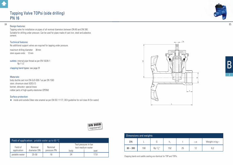
DN
80 – 300
G
Rp 1 1/2 "
h1
152
a
12
L
190
Dimensions and weights t
25
Weight in kg ≈
6,2
B2
Clapping bands and saddle sealing are identical for TOP and TOPsi.
Nominal
diameter DN
25-50
Test pressure in bartest medium water
body seat 24 17,6
Field of application: potable water up to 60 °C
Nominal pressure PN
16
Field of
application
potable water
Tapping Valve TOPsi (side drilling)PN 16
Design features: Tapping valve for installation on pipes of all nominal diameters between DN 80 and DN 300.Suitable for drilling under pressure. Can be used for pipes made of cast iron, steel and asbestos cement.
Technical features: No additional support valves are required for tapping under pressure.
maximum drilling diameter: 38 mmstem square ends: 12 mm
outlets: internal pipe thread as per EN 10226-1: Rp 1 1/2
clapping band types: see page 91
Materials: body ductile cast iron EN-GJS-500-7 as per EN 1563stem: chromium steel X20Cr13bonnet, obturator: special brassrubber parts of high-quality elastomer (EPDM)
Surface protection: • inside and outside Düker etec enamel as per EN ISO 11177, DEV guideline for soil class III (for water)

a
title
ofdata transfer 11
Düker GmbHdate scale different from original
86
3.2
DN
25324050
ø D
32405063
L1
173185210230
Weightin kg ≈
8,39,29,610,1
Dimensions and weights ( Dimensions in mm )
h1
152152152152
h2
247247247247
a
12121212
87
B2
Tapping valves TOP (drilling from above) with PE-HD connection PN 16
Design features: Tapping valve for installation on pipes of all nominal diameters between DN 80 and DN 300.Suitable for drilling under pressure. Can be used for pipes made of cast iron, steel and asbestos cement.
Technical features: No additional support valves are required for tapping under pressure. The resilient valve flap integrated into the type TOP closes automatically after the drilling bar is drawn back.
maximum drilling diameter: 38 mmstem square ends: 12 mm
outlets: pre-installed PE-HD connections as per DVGW G 5600-1 Du 32, Du 40, Du 50, Du 63
clamping band types: see page 91
Materials: body ductile cast iron EN-GJS-500-7 as per EN 1563welding studs: PE 100 SDR 11stem: chromium steel X20Cr13 bonnet, obturator: special brass valve flap: rubberised steelrubber parts of high-quality elastomer (EPDM)
Surface protection: • inside and outside Düker etec enamel as per EN ISO 11177, DEV guideline for soil class III (for water)
Nominal
diameter DN
25-50
Test pressure in bartest medium water
body seat 24 17,6
Field of application: potable water up to 40 °C
Nominal pressure PN
16
Field of
application
potable water

88 89
3.2
B2
Tapping clamp type 88 PN 10/16
Design features:Tapping clamp type 88 with internal pipe thread outlet as per EN 10226-1 for upper or horizontal drilling
Suitable for installation on pipes of all nominal diameters from DN 80 up to DN 300; can be used on pipes of cast iron, steel and asbestos cement. for water
clapping band types: see page 91
Materials:Tapping clamp made of ductile cast iron EN-GJS-500-7 as per EN 1563
Surface protection:• inside and outside powder epoxy resin black RAL 9005 as per GSK guidelines
Test pressure in bar test medium water
body
21
Field of application: potable water up to 60 °C
Nominal pressure PN
16
Field of
application
potable water
Nominal
diameter DN
40 - 50 1"– 2"
DN
80 - 300
Weight in kg ≈ outlet ø d
1" / 1 1/4 " 1 1/2 " / 2"
3 3
Dimensions
* also available as blind clamp

#9190
3.2
Clapping bands for tapping clamps type 88and tapping valves TOP and TOPsi
DN
80100125150175200225250300
Pipe ø 98118144170196222248274326
L335385450520590670750825990
Pipe ø101,6121,6148174200226252278
330,4
L335385450520590670750825990
Pipe ø104126152178—233—288340
L360415480540—700—865
1010
Pipe ø88,9
114,3139,7168,3
—219,1
—273,0323,9
L315385435520—670—825990
Pipe ø—108—159—————
L—370—500—————
Pipe ø100124153182—240—296352
L335385480540—700—865
1030
Dimensions
title
ofdata transfer 11
Düker GmbH & Co. KGaAdate scale di�erent from original
Design features: Flat clapping band for all nominal diameters DN 80 up to DN 300. for pipes made of cast iron (with bituminous, PE or cement mortar coating), steel and asbestos cement PN 12.5The clapping bands are packed as a unit with all required acessories and marked for the pipe type and diameter.
Materials: flat band with welded-on threaded bolts: stainless steel 1.4301, passivated and plastic-coatedcoating: plastic coating black spherical washers: stainless steel 1.4104hexagonal nuts: stainless steel 1.4571 with sliding coatingprotecting caps: plasticssaddle sealing gasket: high-quality elastomer (EPDM) as per DVGW W270 elastomer guideline
cast iron pipe(bituminous
coating)
cast iron pipe(cement mortar
coated)
steel pipe as perEN 10220series 1
cast iron pipe(PE-coated)
steel pipe as perEN 10220series 3
asbestos cement pipe12.5 as per
EN 512
B2
Clapping bands for tapping valvesTOP-Fix and TOP-Drehfix type 1014
DN
80100125150175200225250300
400*
Pipe ø 98118144170196222248274326429
L455505560620690745820890
10301330
Pipe ø101,6121,6148174200226252278
330,4433,4
L465505560620690765820890
10301330
Pipe ø104126152178—233—288340443
L465505560640—
790—
92010601360
Pipe ø88,9
114,3139,7168,3
—219,1
—273,0323,9406,4
L435505560620—
745—
89010301260
Pipe ø—108—159——————
L—475—590——————
Pipe ø100124153182—240—296352470
L465505560640—
790—
94010901440
Dimensions
title
ofdata transfer 11
Düker GmbHdate scale di�erent from original
Design features: Flat clapping band for all nominal diameters DN 80 up to DN 400*. for pipes made of cast iron (with bituminous, PE or cement mortar coating), steel and asbestos cement PN 12.5The clapping bands are packed as a unit with all required acessories and marked for the pipe type and diameter.
Materials: flat band with welded-on threaded bolts: stainless steel 1.4301, passivated and plastic-coatedcoating: plastic coating blue sliding blocks: glass fibre reinforced plastichexagonal nuts: stainless steel 1.4571 with sliding coatingwashers: stainless steel 1.4571protecting caps: plasticssaddle sealing gasket: high-quality elastomer (EPDM) as per DVGW W270 elastomer guideline
cast iron pipe(bituminous
coating)
cast iron pipe(cement mortar
coated)
steel pipe as perEN 10220series 1
cast iron pipe(PE-coated)
steel pipe as perEN 10220series 3
asbestos cement pipe12.5 as per
EN 512
*clapping bands DN 400 on request

t
a
title
ofdata transfer 11
Düker GmbHdate scale different from original
DN
25324050
L
105120130150
h1
132152152178
SW
46556070
G
Rp 1“Rp 1 1/4
„
Rp 1 1/2
„
Rp 2“
t
20242734
a
12121212
Dimensions and weights ( Dimensions in mm )
Weight in kg≈
2,63,84,56,0
92 93
3.2
B2
Service connection valves type 1004 with internal pipe thread PN 16
Design features: Resilient-seated gate valve, with smooth passage, interior stem thread, non-rising stemobturator entirely vulcanisedconnection dimensions: as per EN 10226-1stem square ends: 12 mmface-to-face length: as per EN 16722, basic series M4for potable water or gas
outlets: internal pipe thread as per EN 10226-1: Rp 1, Rp 11/4, Rp 11/2, Rp 2
Operation: • with hand wheel• with stem extension set (for underground installation) – connection as per GW 336-1
Materials: body: ductile cast iron EN-GJS-500-7 as per EN 1563stem: chromium steel X20Cr13 bonnet, obturator: special brassrubber parts of high-quality elastomer:obturator for water: EPDMobturator for gas: NBR
Surface protection:• inside and outside Düker etec enamel as per EN ISO 11177, DEV guideline for soil
class III (for water)• inside and outside epoxy resin blue RAL 5005 as per GSK guidelines (for water, on
request)• inside and outside epoxy resin yellow RAL 1023 as per GSK guidelines (for gas)
Test pressure in bar test medium water test medium air body seat seat PG 3 5 bar 24 17,6
24 0,5 and 6
Field of application: potable water up to 60 ° C; gas as per G 260/I
Nominal diameter DN
25-50 25-50
Nominal
pressure PN
16 5
Field of
application
potable water
gas

DN
25324050
L
345370418460
h1
132152152178
SW
55658595
Weight in kg ≈
3,36,06,28,3
ø D
32405063
a
12121212
L2 min.
102110124140
Dimensions and weights ( Dimensions in mm )
a
title
ofdata transfer 11
Düker GmbHdate scale different from original
9594
3.2
B2
Service connection valves type 1004 with welding studs PE PN 16
Design features: Resilient-seated gate valve, with smooth passage, interior stem thread, non-rising stem obturator entirely vulcanised connection: pre-installed transition pieces as per DVGW G 5600-1 Du 32, Du 40, Du 50, Du 63 with connection dimensions as per DIN 8074/75. Suitable for electric welding and butt welding. stem square ends: 12 mmface-to-face length: as per EN 16722, basic series M4for potable water or gas
Operation: • with hand wheel• with stem extension set (for underground installation) – connection as per GW 336-1
Materials: body: ductile cast iron EN-GJS-500-7 as per EN 1563 welding studs: PE 100 SDR 11 stem: chromium steel X20Cr13 bonnet, obturator: special brass rubber parts of high-quality elastomer: obturator for water: EPDM obturator for gas: NBR
Surface protection:• inside and outside Düker etec enamel as per EN ISO 11177,
DEV guideline for soil class III (for water) • inside and outside epoxy resin blue RAL 5005 as per GSK guidelines
(for water, on request) • inside and outside epoxy resin yellow RAL 1023 as per GSK guidelines (for gas)
Test pressure in bar test medium water test medium air body seat seat PG 3
5 bar
24 17,6 24 0,5 and 6
Field of application: potable water up to 40° C; gas as per G 260/I
Nominal diameter DN
25-50 25-50
Nominal
pressure PN
16 5
SDR
11 11
Field of
application
potable water gas

a
title
ofdata transfer 11
Düker GmbHdate scale different from original
DN
4050
L
280305
h1
152178
K
110125
FT
7075
ø D1
150165
a
1212
Weight in kg ≈
7,3 9,2
Number of screws
44
L2
1919
ø D
5063
Dimensions and weights ( Dimensions in mm )
9796
3.2
B2
Service connection valves type 1004 with flange and welding studs PE PN 16
Design features: Resilient-seated gate valve, with smooth passage, interior stem thread, non-rising stem obturator entirely vulcanisedconnection: pre-installed transition piece as per DVGW G 5600-1Du 40, Du 50with connection dimensions as per DIN 8074/75. Suitable for electric welding and butt welding. flange connection as per EN 1092-2stem square ends: 12 mmface-to-face length: as per EN 16722, basic series M4for potable water or gas
Operation: • with hand wheel• with stem extension set (for underground installation) – connection as per GW 336-1
Materials: body: ductile cast iron EN-GJS-500-7 as per EN 1563 welding studs: PE 100 SDR 11 stem: chromium steel X20Cr13 bonnet, obturator: special brass rubber parts of high-quality elastomer: obturator for water: EPDM obturator for gas: NBR
Surface protection:• inside and outside Düker etec enamel as per EN ISO 11177, DEV guideline for
soil class III (for water)• inside and outside epoxy resin blue RAL 5005 as per GSK guidelines
(for water, on request)• inside and outside epoxy resin yellow RAL 1023 as per GSK guidelines (for gas)
Test pressure in bar test medium water test medium air body seat seat PG 3
5 bar
24 17,6 24 0,5 and 6
Field of application: potable water up to 40° C; gas as per G 260/I
Nominal diameter DN
25-50 25-50
Nominal
pressure PN
16 5
SDR
11 11
Field of
application
potable water gas

9998
3.2
a
t
title
ofdata transfer 11
Düker GmbHdate scale different from original
DN
50
L
320
SW1
95
a
12
SW2
70
h1
178
G
2"
Weight in kg ≈
7,4
t
35
l1
230
ø D
63
Dimensions and weights ( Dimensions in mm )
B2
Service connection valves type 1004 with internal pipe thread and welding studs PE PN 16
Design features: Resilient-seated gate valve, with smooth passage, interior stem thread, non-rising stemobturator entirely vulcanisedconnection: pre-installed transition piece as per DVGW G 5600-1 Du 50with connection dimensions as per DIN 8074/75. Suitable for electric welding and butt welding. internal pipe thread as per EN 10226-1stem square ends: 12 mmface-to-face length: as per EN 16722, basic series M4for potable water or gas
Operation: • with hand wheel• with stem extension set (for underground installation) – connection as per GW 336-1
Materials: body: ductile cast iron EN-GJS-500-7 as per EN 1563 welding studs: PE 100 SDR 11 stem: chromium steel X20Cr13 bonnet, obturator: special brass rubber parts of high-quality elastomer: obturator for water: EPDM obturator for gas: NBR
Surface protection:• inside and outside Düker etec enamel as per EN ISO 11177, DEV guideline for
soil class III (for water)• inside and outside epoxy resin yellow RAL 1023 as per GSK guidelines (for gas)
Test pressure in bar test medium water test medium air body seat seat PG 3
5 bar
24 17,6 24 0,5 and 6
Field of application: potable water up to 40° C; gas as per G 260/I
Nominal diameter DN
25-50 25-50
Nominal
pressure PN
16 5
SDR
11 11
Field of
application
potable water gas

101100
3.2
title
ofdata transfer 11
Düker GmbHdate scale different from original
B2
Gate valve combinations Multi I with Novo sockets PN 10 / 16
Design features: Collar with Novo sockets with lateral outlet combined with gate valve type 1004 DN 50, resilient-seated, with smooth passage, interior stem thread, non-rising stemobturator entirely vulcanisedconnection: pre-installed transition piece as per DVGW G 5600-1with connection dimensions as per DIN 8074/75. Suitable for electric welding and butt welding. in graduated diameters of 63, 50 and 40 mmstem square ends: 12 mm face-to-face length of the gate valve: as per EN 16722, basic series M4for potable water
Operation: • with hand wheel• with stem extension set (for underground installation) – connection as per GW 336-1
Materials: body: ductile cast iron EN-GJS-500-7 as per EN 1563welding studs: PE 100 SDR 11stem: chromium steel X20Cr13 bonnet, obturator: special brassrubber parts of high-quality elastomer:obturator for water: EPDM
Surface protection:• inside and outside Düker etec enamel as per EN ISO 11177, DEV guideline for
soil class III (for water)
Test pressure in bartest medium water
body seat 24 17,6
Field of application: potable water up to 40° C
Nominal diameter DN
25-50
Nominal
pressure PN
16
SDR
11
Field of
application
potable water
DN
100125150200250300
L1
559572585612637663
L2
473486499526551577
Weightin kg ≈
222630404963
Dimensions and weights ( Dimensions in mm )
L3
373386399426451476
L4
183196209236261287
Lu
190195195200200205
t1
123126129138143152
103102
3.3
H
B4 H
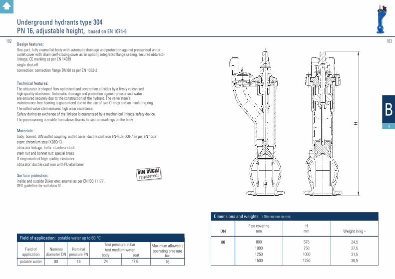
DN
80
Pipe covering mm
800100012501500
H mm
575750
10001250
Dimensions and weights ( Dimensions in mm )
Weight in kg ≈
24,527,531,536,5
Underground hydrants type 304 PN 16, adjustable height, based on EN 1074-6
Design features: One-part, fully enamelled body with automatic drainage and protection against pressurised water, outlet cover with chain (self-closing cover as an option), integrated flange sealing, secured obturator linkage, CE marking as per EN 14339 single shut-off connection: connection flange DN 80 as per EN 1092-2
Technical features: The obturator is shaped flow-optimised and covered on all sides by a firmly vulcanised high-quality elastomer. Automatic drainage and protection against pressurised water are ensured securely due to the construction of the hydrant. The valve stem’s maintenance-free bearing is guaranteed due to the use of two O-rings and an insulating ring. The rolled valve stem ensures high wear resistance.Safety during an exchange of the linkage is guaranteed by a mechanical linkage safety device.The pipe covering is visible from above thanks to cast-on markings on the body.
Materials: body, bonnet, DIN outlet coupling, outlet cover: ductile cast iron EN-GJS-500-7 as per EN 1563stem: chromium steel X20Cr13obturator linkage, bolts: stainless steelstem nut and bonnet nut: special brassO-rings made of high-quality elastomerobturator: ductile cast iron with PU elastomer
Surface protection: inside and outside Düker etec enamel as per EN ISO 11177, DEV guideline for soil class III
Maximum allowable operating pressure
bar16
Test pressure in bartest medium water
body seat 24 17,6
Field of application: potable water up to 60 °C
Nominal diameter DN
80
Nominal
pressure PN
16
Field of
application
potable water

#105104
H
B4
DN
80
Pipe covering mm
800100012501500
H mm
575750
10001250
Dimensions and weights ( Dimensions in mm )
Weight in kg ≈
25,028,032,037,0
Underground hydrants type 305 PN 16, adjustable height, based on EN 1074-6
Design features: One-part, fully enamelled body with automatic drainage and protection against pressurised water, outlet cover with chain (self-closing cover as an option), integrated flange sealing, secured obturator linkage, CE marking as per EN 14339 double shut-off connection: connection flange DN 80 as per EN 1092-2
Technical features: The obturator is shaped flow-optimised and covered on all sides by a firmly vulcanised high-quality elastomer. Automatic drainage and protection against pressurised water are ensured securely due to the construction of the hydrant. The valve stem’s maintenance-free bearing is guaranteed due to the use of two O-rings and an insulating ring. The rolled valve stem ensures high wear resistance.Safety during an exchange of the linkage is guaranteed by a mechanical linkage safety device.The pipe covering is visible from above thanks to cast-on markings on the body.
Materials: body, bonnet, DIN outlet coupling, outlet cover: ductile cast iron EN-GJS-500-7 as per EN 1563stem: chromium steel X20Cr13obturator linkage, bolts: stainless steelstem nut and bonnet nut: special brassO-rings made of high-quality elastomerobturator: ductile cast iron with PU elastomersealing ball: steel with EPDM cover
Surface protection: inside and outside Düker etec enamel as per EN ISO 11177, DEV guideline for soil class III
Maximum allowable operating pressure
bar16
Test pressure in bartest medium water
body seat 24 17,6
Field of application: potable water up to 60 °C
Nominal diameter DN
80
Nominal
pressure PN
16
Field of
application
potable water
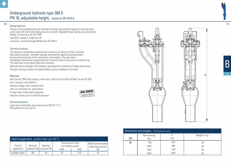
H
107106
3.3
B4
Underground hydrants type 304 S PN 16, adjustable height, based on EN 1074-6
DN
80
Pipe covering mm
750100012501500
H mm
670890
11401390
Dimensions and weights ( Dimensions in mm )
Weight in kg ≈
29333843
Design features: One-part, fully enamelled body with automatic drainage and protection against pressurised water, outlet cover with chain (self-closing cover as an option), integrated flange sealing, secured obturator linkage, CE marking as per EN 14339Type 304 S, design A: single shut-offconnection: connection flange DN 80 as per EN 1092-2
Technical features: The obturator is shaped flow-optimised and covered on all sides by a firmly vulcanised high-quality elastomer. Automatic drainage and protection against pressurised water are ensured securely due to the construction of the hydrant. The valve stem’s maintenance-free bearing is guaranteed due to the use of two O-rings and an insulating ring. The rolled valve stem ensures high wear resistance.Safety during an exchange of the linkage is guaranteed by a mechanical linkage safety device.The pipe covering is visible from above thanks to cast-on markings on the body.
Materials: body, bonnet, DIN outlet coupling, outlet cover: ductile cast iron EN-GJS-500-7 as per EN 1563stem: chromium steel X20Cr13obturator linkage, bolts: stainless steelstem nut and bonnet nut: special brassO-rings made of high-quality elastomerobturator: ductile cast iron with PU elastomer
Surface protection: inside and outside Düker etec enamel as per EN ISO 11177, DEV guideline for soil class III
Maximum allowable operating pressure
bar16
Test pressure in bartest medium water
body seat 24 17,6
Field of application: potable water up to 60 °C
Nominal diameter DN
80
Nominal
pressure PN
16
Field of
application
potable water

#109108
Underground Hydrant Type 306 for Chamber Installation DN 65 PN 16, as per EN 1074-6
DN
80
Pipe covering mm
800
H mm
575
Dimensions and weights ( Dimensions in mm )
Weight in kg ≈
24
Design features: One-part, fully enamelled body with automatic drainage and protection against pressurised water, integrated flange sealing, secured obturator linkagesingle shut-offclosing anti-clockwise (clockwise closing on request)connection: connection flange DN 65 as per EN 1092-2 and factory standard, 8 hole drilling (double drilling as per „Württemberger chamber system“ for flexible positioning)
Materials: body, bonnet, DIN outlet coupling, outlet cover: EN-GJS-500-7Massive obturator linkage, stem: X20Cr13stem nut and bonnet nut in special brassobturator: PU elastomer
Surface protection: inside and outside Düker etec enamel as per EN ISO 11177, DEV guideline for soil class III
Test pressure in bartest medium water
body seat 24 17,6
Field of application: potable water up to 60 °C
Nominal diameter DN
65
Nominal
pressure PN
16
Field of
application
potable water
B4
Flange DN 65 as per local Württemberg standard
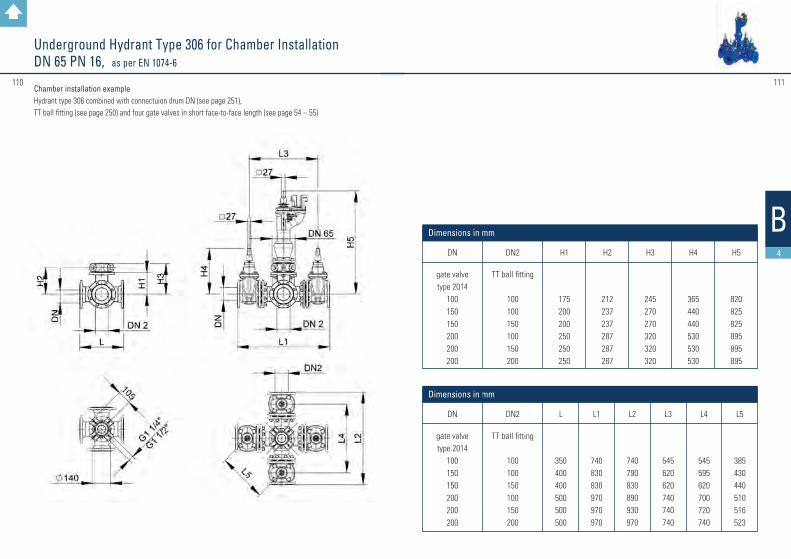
#111110
Underground Hydrant Type 306 for Chamber Installation DN 65 PN 16, as per EN 1074-6
Chamber installation example Hydrant type 306 combined with connectuion drum DN (see page 251),TT ball fitting (see page 250) and four gate valves in short face-to-face length (see page 54 – 55)
B4DN
gate valvetype 2014
100150150200200200
DN2
TT ball fitting
100100150100150200
H1
175200200250250250
H2
212237237287287287
H3
245270270320320320
H4
365440440530530530
H5
820825825895895895
Dimensions in mm
L
350400400500500500
L1
740830830970970970
L2
740790830890930970
L3
545620620740740740
L4
545595620700720740
L5
385430440510516523
Dimensions in mm
DN
gate valvetype 2014
100150150200200200
DN2
TT ball fitting
100100150100150200

Design features: Pillar hydrant with additional shut-off, automatic drainage and protection against pressurised water, safety lock of the internal mountings, traffic-area version with installation-friendly pre-determined breaking pointCE marking as per EN 14384connection: connection flange as per EN 1092-2
Technical features: maintenance-free bearing of the stem extension
Materials: bottom, upper and lower part of the pillar, and bonnet nut: ductile cast iron EN-GJS-500-7 as per EN 1563operating cap, outlets and outlet covers: aluminiumstem: chromium steel X20Cr13linkage, pin, drainage plate, bolts: stainless steelstem nut, stem bearing, predetermined breaking coupling and bonnet nut: special brassseat ring: rubberized brass O-rings made of high-quality elastomerobturator: entirely vulcanized with high-quality elastomer (EPDM)
Surface protection: • inside Düker enamel• bottom and lower part of the pillar outside: base coat enamel with epoxy resin cover coat signal
red RAL 3001• upper part of the pillar outside: base coat enamel, cover coat 2-components PU paint signal red
RAL 3001• on request: upper part of the pillar inside Düker etec enamel blue, outside Düker enamel in the shades:
red blue yellow lemon green light grey anthracite
DN
808080
100100100
Pipe covering mm
100012501500100012501500
L2
105010501050105010501050
L1
194021902440194021902440
L3
680680680680680680
L4
———355355355
e
———200200200
L5
555555555555
Dimensions and weights ( Dimensions in mm )
Weight in kg ≈
125136147129140151
112 113
3.3
B4
Pillar hydrants Type 494, design AUD PN 16, adjustable height, based on EN 1074-6
Maximum allowable operating pressure
bar16
Test pressure in bartest medium water
body seat 24 17,6
Field of application: potable water up to 60 °C
Nominal diameter DN
80-100
Nominal
pressure PN
16
Field of
application
potable water
DN
L4
L2
L3
drehbareAusführung
e
L1
L5
rotatable version

DN
100100
Pipe covering mm
12501500
L2
12501250
L1
23902640
L3
950950
L4
355355
ø d
400400
L5
5555
e
200200
Dimensions and weights ( Dimensions in mm )
Weight in kg ≈
185185
115114
3.3
Design features: Pillar hydrant with additional shut-off, automatic drainage and protection against pressurised water, safety lock of the internal mountings, traffic-area version with installation-friendly pre-determi-ned breaking point, 2 upper valve outlets B below the protective cover, 1 lower valve outlet ACE marking as per EN 14384connection: connection flange as per EN 1092-2
Technical features: maintenance-free bearing of the stem extension
Materials: bottom, upper and lower part of the pillar, valve head and hand wheel: ductile cast iron EN-GJS-500-7 as per EN 1563outlets and outlet covers: aluminiumprotective cover: steel X5CrNi18-10stem: chromium steel X20Cr13linkage, pin, drainage plate, bolts: stainless steelstem nut, stem bearing, predetermined breaking coupling and bonnet nut: special brassseat ring: rubberized brass O-rings made of high-quality elastomerobturator: entirely vulcanized with high-quality elastomer (EPDM)
Surface protection: • inside Düker enamel• bottom and lower part of the pillar outside: base coat enamel with epoxy resin
cover coat signal red RAL 3001• upper part of the pillar outside: base coat enamel, cover coat 2-components
PU paint signal red RAL 3001
• on request: upper part of the pillar inside Düker etec enamel blue, outside Düker enamel in the shades:
red blue yellow lemon green light grey anthracite
B4
Pillar hydrants type 495, design AFUD PN 16, adjustable height, based on EN 1074-6
Maximum allowable operating pressure
bar16
Test pressure in bartest medium water
body seat 24 17,6
Field of application: potable water up to 60 °C
Nominal diameter DN
100
Nominal
pressure PN
16
Field of
application
potable water

116 117
3.4
B5
Butterfly valves type 451 and 4510 with flanges PN 10/16/25
DN 800 up to 1200 in PN 25 only for operating pressure up to 20 bar
Design features: Resilient-seated butterfly valve with slidercrank gear box flow-optimised, completely enamelled valve disc with double eccentric journal square plug connection between valve disc and shaft easily replaceable profile sealing mechanical position indication open/closed on the gear box cover driving shaft and bearing journal chambered medium-free flange connection dimensions: as per EN 1092–2 face-to-face length: as per EN 558, basic series 14 for potable water or gas
Operation: • with hand wheel • with stem extension (for underground installation) – connection as per GW 336-1 • with electrical actuator (on request) • with pivot drive • with pneumatic drive • with hydraulic drive • with end switch unit
Materials: body, valve disc: ductile cast iron EN-GJS-400-15 as per EN 1563retaining ring: EN-GJS-500-7; from DN 700 up stainless steel 1.4301 profile sealing for water: EPDM profile sealing for gas: NBR driving shaft: chromium steel X20Cr13 bearing bushes: red bronze CC483 K
Surface protection: • DN 100 up to 600 inside and outside Düker etec enamel as per EN ISO 11177, DEV guideline for
soil class III (for water)• from DN 700 up inside Düker enamel, outside 2-components epoxy resin blue RAL 5005 (for water) • inside Düker enamel, outside PUR on request (for water)• inside Düker enamel, outside two-components paint yellow RAL 1023 (for gas)
Nominal diameter DN
100 – 1200100 – 1200100 – 1200100 – 1200100 – 1200
Field of application
potable waterpotable waterpotable water
gasgas
Nominal pressure PN
1016251016
Allowable operating pressure
bar
1016251016
test medium air
seat PG 3
———
0,5 and 11 0,5 and 17,6
test medium water
body seat
15 11 24 17,6 37,5 27,5 15 11 24 17,6
Field of application: potable water up to 60 °CTest pressure in bar

118 119
3.4
B5
Butterfly valves type 451 and 4510 with flanges PN 10 / 16 / 25
l
➜
DN
700700700 8008009009001000100012001200
PN
1016251016101610161016
L
430430430470470510510550550630630
Gearbox SKIV B
IV B GPIV B GPIV B GPIV B GPIV B GP
GS 200 GZIV B GP
GS 250 GZGS 250 GZGS 250 GZ
D
89591096010151025111511251230125514551485
B
400400450450450550550600600700700
h1
450460485510515560568620630730750
h2
570745745745745745675745715715715
t1
549549549594594634634699699828828
t2
665665665710710750740815805903903
x1
150150150150150150200150255255255
d1
500400400400400400400400640640640
Weight * kg
650665750902917
120012631490166020702140
Butterfly valves type 4510
Butterfly valves type 451
Dimensions and weights ( Dimensions in mm )
GP and GZ = with reduction gear * with hand wheel
DN
100100125125150150200200200250250250300300300350350350400400400500500500600600600
PN
10/16 25
10/1625
10/162510 16251016 25 1016 25 1016 25 1016 25 101625 1016 25
L
190190200200210210230230230250250250270270270290290290310310310350350350390390390
Gearbox SKI BI BI BI BI BI BII BII BII BII BII BII BII BII BII BII BII BIII BII BIII BIII BIII BIII BIV BIII BIV B
IV B GP
D
220235250270285300340340360400400425455455485505520555565580620670715730780840845
B
120120130130150150160160160180180180200200200225225225300300300350350350320330400
h1
116121131141149157177177187208208220233233248259269287294294319350372375401431431
h2
325325325325325325325325325325325325325325325325325325325315315315315535315500500
t1
110110122122138138175175175212212212221221221287287287307307307377377385442442442
t2
258258270270286286311311311348348348371371371426426426446474474524524571614673693
x1
65656565656565656565656565656565656565
100100100100160100160160
d1
200200250250250250250250250250250250250250250250250250250315315315315500315500500
Dimensions and weights ( Dimensions in mm )
Weight * kg3334383944445656617574819297105116123145149192216246276395348506537

#121120
3.4
B5
Butterfly valves type 451 and 4510 with flanges PN 10/16/25 Long face-to-face length, with or without bypass
Nominal diameter DN
100 – 1000100 – 1000
Field of application
potable waterpotable water
Nominal pressure PN
1016
Allowable operating pressure
bar
1016
Test pressure in bar
test medium water body seat
15 11 24 17,6
Field of application: potable water up to 60 °C
Design features: Resilient-seated butterfly valve with slidercrank gear box flow-optimised, completely enamelled valve disc with double eccentric journal square plug connection between valve disc and shafteasily replaceable profile sealingmechanical position indication open/closed on the gear box coverdriving shaft and bearing journal chambered medium-freeflange connection dimensions: as per EN 1092–2face-to-face length: as per EN 558, basic series 15with bypass (without bypass on request)bypass approx. 1/10 of the main diameterfor potable water
Operation: • with stem extension – connection as per GW 336-1
Materials: body, valve disc: ductile cast iron EN-GJS-400-15 as per EN 1563retaining ring: EN-GJS-500-7; from DN 700 up stainless steel 1.4301 profile sealing for water: EPDM driving shaft: chromium steel X20Cr13 bearing bushes: red bronze CC483 K
Surface protection: • DN 100 up to 600 inside and outside Düker etec enamel as per EN ISO 11177, DEV guideline for
soil class III (for water)• from DN 700 up inside Düker enamel, outside 2-components epoxy resin blue RAL 5005 (for water)
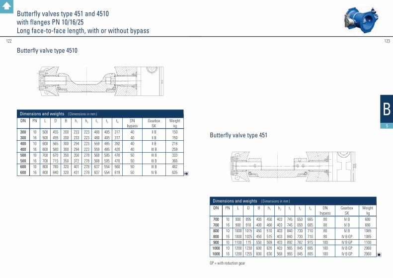
#123122
3.4
B5
Butterfly valves type 451 and 4510 with flanges PN 10/16/25 Long face-to-face length, with or without bypass
l
➜
DN
300300400400500500600600
DN
70070080080090010001000
PN
10 161016101610 16
PN
10 161016101016
L
500500600600700700800800
L
900900
10001000110012001200
Gearbox SKII BII BII BIII BIII BIII BIII BIV B
Gearbox SKIV BIV BIV B
IV B GPIV B GPIV B GPIV B GP
D
455455565580670715780840
D
8959101015102511512301255
B
200200300300350350320320
B
400400450450550600600
h1
233233294294350372401431
h1
450460510515569620630
h2
223223223223278278278278
h2
403403403403403403568
t1
480480559559568568637637
t1
745745840840892965965
t2
405405485485505505554554
t2
650650730730782845845
t4
317317392420470470560619
t4
665665710710915805805
DN bypass
4040404050505050
DN bypass
80808080
100100100
Dimensions and weights ( Dimensions in mm )
Dimensions and weights ( Dimensions in mm )
Weight kg150150218259333366462635
Weight kg680680
10851085110020602060
Butterfly valve type 4510
Butterfly valve type 451
GP = with reduction gear

125124
3.4
B5
Butterfly valves type 4510 with Novo sockets PN 10/16/25
Design features: Resilient-seated butterfly valve with slidercrank gear boxflow-optimised, completely enamelled valve disc with double eccentric journal square plug connection between valve disc and shaft easily replaceable profile sealingmechanical position indication open/closed on the gear box cover driving shaft and bearing journal chambered medium-freeconnection: plug-in sockets as per DIN 28603 TYTON® with pre-chamberface-to-face length: as per EN 558, basic series 14for potable water
Operation: • with hand wheel• with stem extension (for underground installation) – connection as per GW 336-1 • with electrical actuator (on request) • with pivot drive • with pneumatic drive • with hydraulic drive • with end switch unit
Materials: body, valve disc: ductile cast iron EN-GJS-400-15 as per EN 1563retaining ring: EN-GJS-500-7 driving shaft: chromium steel X20Cr13 bearing bushes: red bronze CC483 K
Surface protection: • inside and outside Düker etec enamel as per EN ISO 11177, DEV guideline for
soil class III (for water)
Nominal diameter DN
150 – 500150 – 500150 – 500
Field of application
potable waterpotable waterpotable water
Nominal pressure PN
101625
Allowable operating pressure
bar
101625
Test pressure in bar
test medium water body seat
15 11 24 17,6 37,5 27,5
Field of application: potable water up to 60 °C
DN
150200250300400400500500
PN
10 – 2510 – 2510 – 2510 – 25
1016 – 2510/16
25
L
398428453484480480543543
Gearbox SKI BII BII BII BII BIII BIII BIV B
D
360383398413472472527527
B
150160180200250250300300
h1
147175205230285285340340
h2
300300300380380380400400
t1
177202248263263328370370
t2
231256300317317382465465
Dimensions and weights ( Dimensions in mm )
Weight kg425775
106187187257257
ETE
145156170183181181213213

#127126
B5
Butterfly valves Special versions
Butterfly valve with block flanges
• long face-to-face length EN 558 basic series 15 with or without bypass
• with vertical block flanges for the mounting of a ventilation before and after the body seat
available on request
Butterfly valve with locking device
• with locking flange at the blind side opposite the gear box
The locking flange allows to secure the valve disc in the OPEN or CLOSED position. This way it is possible to exchange the gear box during operation.
available on request
Butterfly valve “UVV“ with 3-point locking
• for repair and inspection work in walk-in pipeline systems
• two fixed stops, one movable stop
At the movable stop, a bolt glides into the body, operated by a hand wheel, and blocks the closed valve disc. The two fixed stops are unmovable in the body. As an option, there is the possibility for an additional mechanical locking of the bolts, or a position control with a limit switch.
available on request

#129128
B5
Butterfly Valves for Installation Between Flanges Type Series 480 – 488, PN 16
Nominal diameter DN
25 – 200
250 – 600
Field of application
potable water
potable water
Nominal pressure PN
16
16
Allowable operating pressure in bar
16
10*
10
6*
Field of application: potable water, raw water
Design features: Resilient-seated centric butterfly valve as per EN 593„Wafer“ version for clamping between pipeline flanges PN 10/16 as per EN 1092-2„Lug“ version for screwed flange connection or as an end valveflow-optimised ground butterfly disc with rounded edgestem medium-free, one or two part design depending on the nominal diameterloose collar sealing, easy to exchangespecial profiled contour to allow for installation in the pipeline without additional flange sealing length: as per EN 558, basic series 20for water
Operation: • type 480 without operating device
• type 487 with hand lever (up to DN 200)
• type 487 with gear box and hand wheel (from DN 250)
• type 488 with electric actuator
• type 481 with pneumatic actuator
Materials: body: ductile cast iron EN-GJS-400-15 as per EN 1563disc: stainless steel 1.4408collar sealing: EPDMstem: 1.4021hand lever: aluminiumgear box: aluminium PU-coated; from DN 450 GG25 PU-coated
Surface protection: • inside and outside epoxy powder coating sky blue RAL 5015, layer thickness min. 250 µm
* when used as an end flange. In this case, the valve must be equipped with a counterflange.
Test pressure in bar body
24
24
seat
17,6
17,6
with hand lever (DN 25 – 200)
Type 487 Wafer version for clamped installation
DN2540506580
100125150200250300350400450450500600600
PS161616161616161616161616161016101016
D607691
111130150179210264314364440485541541600700700
B4154606890
105120132160295236266308333333358442442
L2302382462562652753603754724975222202432727
300350350
L1121121121121121121171171195195195293376465465465480480
H231264270298325361397452550610676925993
12051205125613721372
H1190210210230235256277320390415440159685872872898930930
H290909090909090
120150150150338338500500500410410
C253343464652565660687878
102114114127154154
M156156156156156156156186221221221428428486486486486486
N43434343434343435050508080868686105105
R100100100100100100100160200200200500500800800800700700
kg2,02,33,84,44,86,38,49,514,123,632,252,776,7109,0109,0134,0214,0214,0
Dimensions and weights ( Dimensions in mm )
D
B
H1
H
H2
L1 L
C
M
D
B
H2
L1
H1
H
L M
C
D
B
H1
H
L L1
H2
C
M L1
H2
SAHL
Wafer Lug
U-Sektion
D
B
L1 L
H1
H
R H
2
C
N M
D
B
L L1
R
H1
H
H2
M
C
N
D
B
L L1
H1
H
H2
R
C
N M
Wafer Lug
U-Sektion
with gear box and hand wheel (DN 250 – 600)
with hand lever
with gear box and hand wheel
DN2540506580
100125150200
PS161616161616161616
D607691
111130150179210264
B4154606890
105120132160
L230238246256265275360375472
L1200200200200200200270270340
H211244250278305341397422740
H1170190190210215236277290580
H27070707070709090
340
C253343464652565660
M747474747474102102126
kg1,51,83,33,94,35,88,29,313,4

#131130
B5
with hand lever (DN 25 – 200)
Type 487 Lug version for screwed flange connection
DN506580
100125150200200250250300300350350400400
PS16161616161610161016101610161016
D151171188219250275330330402402472472520520596596
B606789
103119131171171203203236236260260300300
L197207215230296309360360396396431431553553674674
L1121121121121171171195195195195195195293293376376
H270297324359396451561561618618676676919919985985
H1210230235256277320390390415415440440159159185185
H29090909090
120150150150150150150338338338338
C4346465256566060686878787878
102102
M156156156156156186221221221221221221428428428428
N43434343434350505050505080808080
R100100100100100160200200200200200200500500500500
kg4,54,87,88,3
11,914,922,422,433,433,444,444,470,770,7
114,7114,7
Dimensions and weights ( Dimensions in mm )
D
B
H1
H
H2
L1 L
C
M
D
B
H2
L1
H1
H
L M
C
D
B
H1
H
L L1
H2
C
M L1
H2
SAHL
Wafer Lug
U-Sektion
D B
L1 L
H1
H
R H
2
C
N M
D
B
L L1
R
H1
H
H2
M
C
N
D
B
L L1
H1
H
H2
R
C
N M
Wafer Lug
U-Sektion
with gear box and hand wheel (DN 250 – 600)
with hand lever
with gear box and hand wheel
Butterfly Valves for Installation Between Flanges Type Series 480 – 488, PN 16
DN506580
100125150200
PS16161616161616
D151171188219250275330
B606789
103119131171
L276286294309395408505
L1200200200200270270340
H250277304339396421751
H1190210215236277290580
H2707070709090
340
C43464652565660
M74747474
102102126
kg4
4,37,37,8
11,714,721,7

#133132
B6
Non-slam check valve type 8015 PN 10/16/25/40
Design features: Hydraulically optimised backflow preventer for industrial water applications, water collection, pumping stations etc.
nominal diameters DN 80 up to DN 300
flange connection dimensions as per EN 1092-2
nominal pressure PN 10 up to PN 40
face-to-face length as per EN 558, basic series 14
Design: for flow direction
• H+V horizontal and vertical upwards
• or V vertical downwards
Materials:
body and body insert: ductile cast iron EN-GJS-500-14
valve disc: ductile cast iron, completely rubberized with elastomer as per elastomer guidelines and DVGW worksheet W270
guide rod: stainless steel 1.4057
threaded bush: stainless steel 1.4057
spring: stainless steel 1.4310
guidance bush: polymer as per plastics guidelines and DVGW worksheet W270
Surface protection:
• inside and outside Düker etec enamel as per EN ISO 11177
K
f x 45° C
d
L
D
DN 250 and DN 300 upon request
DN
80100100125125125150150150200200200200250250250250300300300300
Dimensions in mm
PN
10/16/25/4010/1625/4010/16
2540
10/162540101625401016254010162540
L
180190190200200200210210210230230230230250250250250270270270270
ø D
200220235250270270285300300340340360375400400425450455455485515
ø K
160180190210220220240250250295295310320350355370385400410430450
ø d
132156156184184184211211211266266274284319318330345370370389409
f
333333333333333334444
C
1919191919
23,5192026202022302222
24,534,524,524,527,539,5
Number ofbolts
88888888881212121212121212121616
Nominal diameter
DN
80 – 30080 – 30080 – 30080 – 300
Field of application
waterwaterwaterwater
Nominal pressure
PN
10162540
Allowable operating pressure
bar
10162540
Test pressure in bartest medium water
body seat flow direction back flow direction
15 24 37,5 60
Field of application: water up to 60 °C
1117,627,544
0,50,50,50,5

#135134
B6
Air valves D-46 PN 16 (operating pressure 0,2 – 16 bar)
Nominal diameter DN
50 – 100
Nominal pressure PN
16
Sealing system
0,2 – 16 bar
Field of application: potable water, raw water
Design features: three-way aeration and air release valve
with integrated adjustable non-slam throttle disc as an active pressure surge buffer
flange as per EN 1092-2, body enamelled inside and outside
Large orifice for ventilation and air release up to 7,854 mm², for start-up air release or for aeration in case of negative pressure in the pipeline.
Small orifice for operational air release up to 13 mm², floater-controlled for permanent efficiency by air-free transport.
Materials:
body: EN-GJS
connection for aeration and air release, protective grating, floater, drainage: PP
non-slam throttle disc, throttle insert, clamping ring: PAGF
sealing gaskets: EPDM
Surface protection:
• Düker enamel inside and outside
Performance data:
174
863
DN
5080100
Dimensions and weights ( Dimensions in mm )
PN
161616
Dimensions
Dimensions see drawings
Weight in kg ≈
7,214,220,7
DN 50 DN 100DN 80
467
227
538
248
Air Release with Fully Open Non-Slam Thro�le Disc
two-stage start-up air release [m³/h]100 200 300 400 500
0,2
0,4
0,6
0,8
1,0
DN 50 DN 80 DN 100
laicnereffidpr
essu
re[b
ar]
Permanent Opera�onal Air Release
wor
king
pres
sure
[bar
]
air release [m³/h]10 20 30 40 50 60
25
20
15
10
5

#137136
B7
Plunger Valve RKV Type 7015 PN 10/16/25/40
Design features: Shut-off and control valve for pressure adjustment and flow quantity limiting,one-part body with eye bolts, ring-shaped passage,sealing both ways, leak tightness as per EN 1266-1 leak rate A,optimised flow channelling, guide rails for the piston in the body made of stainless steel of superior hard-ness, fixed firmly in the body – without bolting or welding,sturdy low-wear profile sealing ring on the piston, piston rotatable in case of wearcontrol insert seat ringoptional:control insert slotted cylindercontrol insert special versionflanges as per EN 1092-2, type 21, shape Bface-to-face length as per EN 558 basic series 15for water
Gear box: sturdy, self-impeding maintenance-free slidercrank gearbox with adjustable end stop,connection flange to the body secured against rotating with a pin,adjusted torque curve due to toggle lever hinge,IP Code 68, mechanical position indicatorstandard position: right-hand in flow direction as per drawing 321385 pos. 1other gearbox positions as an option
Operation: • gear box with hand wheel
• gear box with electric actuator
• further versions on request
Materials: body: EN-GJS-500-14guiding rails: stainless steel of superior hardness, highly corrosion-resistantpiston/slotted cylinder: 1.4301seat ring: 1.4301shaft, thrust rod, gear crank: 1.4057 high-strength stainless steelbearing bushes: bronze CC483Kclamp ring: 1.4301
Test pressure in bartest medium water
body seat 15 11
24 17,6
37,5 27,5
60 44
Field of application: potable water, raw water up to 60 °C
Nominal diameter DN
150 – 300
150 – 300
150 – 300
150 – 300
Nominal pressure
PN
10
16
25
40
Field of
application
water
water
water
water
Surface protection: inside and outside epoxy finish blue RAL 5005 as per GSK guidelines
Data for individual design: upstream pressure: _____ bardownstream pressure: _____ barflow rate min.: _____ l/sflow rate max.: _____ l/sA detailed questionnaire can be found at:www.dueker-germany.com/fittings-and-valves/downloads
Functioning of the Düker plunger valve: An animation regarding the functioning and specialities can be found at:www.dueker-germany.com/film
to the questionnaire to the film

#139138
B7
Plunger Valve RKV Type 7015 PN 10/16/25/40
DN 250, 350 and 400 in preparation * Version with slotted cylinder in closed position
DN
150150150150200200200200300300300300
PN
101625401016254010162540
ø D
300300300300340340360375455455485515
ø d
211211211211266266274284370370389409
ø K
240240250250295295310320400410430450
ø L
232328282323283123283134
n
8888812121212121616
C
2626262620202233
24,524,527,539,5
f
333333334444
A
350350350350400400400400500500500500
B1
262262262262292292292292421421421421
B2
62,562,562,562,562,562,562,562,585858585
E1
190190190190220220220220321321321321
Dimensions in mm
d
data sheet
E2
131,3131,3131,3131,3140140140140150150150150
ø G
236236236236309309309309453453453453
H1
201201201201242242242242313313313313
H2
156156156156197197197197268268268268
H3
170170170170170170170170228228228228
L1
140140140140140140140140180180180180
L2
170170170170170170170170200200200200
H4
291291291291291291291291379379379379
E3
165165165165165165165165257257257257
ø N
200200200200200200200200315315315315
S*
50505050
ø T*
112112112112
Dimensions in mm
d
data sheet
Design with hand wheel
actuator right-hand in flow direction
Dimensions according tomanufacturer’s data sheet
Design with hand wheel
Dimensions according tomanufacturer’s data sheet
actuator left-hand in flow direction

#141140
B7
Plunger Valve RKV Type 7015 PN 10/16/25/40
Versions Versions
with seat ring
with slotted cylinder
special version: with perforated cylinder with hand wheel
with electric actuator

143142
3.5
Novo plug-in system
On the following pages you will find items which are particularly suited for use in the Novo plug-in system.
Further items can be found here:
Gate valves type 4014 with Novo sockets page 56-57
Gate valves type 4014 with Novo socket and spigot end page 58-59
Butterfly valves type 4510 with Novo sockets page 124-125
Underground hydrants type 304 S design A page 106-107
Flanged socket duckfoot bends 90° with Novo sockets page 242MMN/MMNR
Single socket tees with spigot and socket branch page 208B
B8

145144
B8
DN
80 80 80100125150
Lu
150200300400400400
e
7,0 7,0 7,0 7,2 7,8 8,4
Weight
in kg ≈
5,07,08,010,519,529,5
Dimensions and weights
Dimensions in mm
Pipe sections with Novo socket – Macc. to manufacturer’s standardPN 10/16
Suitable as hydrant extension
Surface protection: • inside Düker enamel as per EN ISO 11177 • outside bituminous coating
Smooth pipe sections with spigot ends – Sas per EN 545PN 10/16
for gate valves with socket connection
Surface protection: • inside Düker enamel as per EN ISO 11177 • outside bituminous coating
DN
80100150200
L
800800800800
ø d
98118170222
e
7,0 7,2 7,5 7,8
Weight
in kg ≈
12,015,020,030,0
Dimensions and weights
Dimensions in mm

147146
B8
3.5
Collars with Novo and screw-gland socketacc. to manufacturer’s standardPN 10/16
DN
80100150200300
Lu
160160165170180
ø d
109130183235340
e
7,0 7,27,88,49,6
Weight in kg ≈
PN 16
10,013,522,527,036,0
Dimensions and weights
Dimensions in mm
Collars with Novo sockets – Uacc. to manufacturer’s standardPN 10/16
DN
80100125150
Lu
160160165165
ø d
109130156183
e
7,0 7,2 7,5 7,8
Weight
in kg ≈
10,013,515,522,5
Dimensions and weights
Dimensions in mm
Surface protection: • inside Düker enamel as per EN ISO 11177 • outside bituminous coating
Surface protection: • inside Düker enamel as per EN ISO 11177 • outside bituminous coating

#149148
3.5
B8
All spigot teesacc. to manufacturer’s standardwith one socket – MI, with spigots – IT PN 10/16
➜
DN 1
80
100
125
DN 2
40 50 80 40 50 80100 40 50 80100125
L1
540
550
600
L2
270
275
300
e1
7,0
7,2
7,5
e2
7,07,07,07,07,07,07,27,07,07,07,27,5
12,012,513,012,013,014,515,017,019,020,021,024,0
Weight in kg ≈
Dimensions in mm
DN 1
80
100
125
DN 2
80
80100
80100125
L1
455
460
510
L2
270
275
300
e1
7,0
7,2
7,5
e2
7,0
7,07,2
7,07,27,5
14,0
16,817,0
22,523,526,5
Weight in kg ≈
Dimensions in mm
All spigot end tee Single socket tee
Dimensions and weights
for gate valves with socket connectionMI with Novo or TYTON® socket
Surface protection: • inside Düker enamel as per EN ISO 11177 • outside bituminous coating
l
DN 1
150
200
250*
300*
DN 2
40 50 80100125150 80100125150200 80100150200250 80100150200300
l1
620
650
870
870
l2
310
325
435
435
e1
7,8
8,4
9,0
9,6
e2
7,07,07,07,27,57,87,07,27,88,49,07,07,27,88,49,07,07,27,88,49,6
21,522,523,024,525,026,734,035,036,036,538,545,047,048,551,555,064,568,070,072,077,0
Weight in kg ≈
Dimensions in mm
DN 1
150
200
250
300
DN 2
80100125150
80 100 125 150 200 100 150 200 250
80 100 150 200 300
l1
525
550
705
760
l2
310
325
405
435
e1
7,8
8,4
9,0
9,6
e2
7,07,27,57,8
7,07,27,57,88,47,27,88,49,0
7,07,27,88,49,6
27,028,029,030,0
37,0 38,0 39,0 40,0 43,0 60,0 62,0 65,5 66,0
77,0 82,0 86,0 84,0103,0
Weight in kg ≈
Dimensions in mm
Dimensions and weights
All spigot end tee Single socket tee
* acc. to manufacturer’s standard material: ductile iron EN-GJS-500-7, inside enamel material: ductile iron EN-GJS-500-7, inside enamel socket NOVO-SIT® as per manufacturer‘s standard

151150
B8
PE adapter pieces for Novo socketsacc. to manufacturer’s standardPN 10/16
Thrust resisting adapter piece for fittings, gate valves and butterfly valves for plug-in sockets NOVO-SIT® PE adapter piece with pre-installed support sleeve and circumferential retaining ringfor retaining the locking segments; PE spigot end for all usual welding procedures, SDR 11for water, transition from ductile cast iron to PE
Materials: • fitting: PE 100 black • support sleeve and retaining ring: stainless steel
DN
80100100125150150200200
L
290315340355360380410426
ø d
90110125140160180200225
e
8,2 10,011,212,814,616,418,220,5
Weight
in kg ≈
1,32,252,63,34,05,57,07,8
Dimensions and weights
Dimensions in mm

153152
3.6
B9
Fig. 125 with flange connection PN 10 / 16
DN
50 65 80100125150200250300350400
Face-to-face dimension
L ≈
210210210250250280300350360390390
Weight in
kg ≈
5,5 7,6 9,4 13,0 16,0 22,0 35,0 60,0 70,0 92,0117,0
Dimensions and weights
Flap valves figure 125 PN 10/16
Design features: Flange connection dimensions: as per EN 1092–2for potable water
Materials: body and bonnet: ductile cast iron EN-GJS-500-7 as per EN 1563flap shaft: brassflap sealing: elastomer
Surface protection: • inside and outside epoxy resin black RAL 9005 as per GSK guidelines (for water)
Field of application: potable water up to 60 °C
Nominal diameter DN
200-400 50-400
Nominal pressure
PN
10 16
Field of
application
potable water potable water

#155154
B9
Laying tool V 300 Dfor pressure pipes, fittings and gate valves with TYTON® sockets
DN
80100125150200250300400
Lever length
mm
10501050105010501050105010501050
Weight in kg ≈
16,517,017,518,521,023,524,526,0
Dimensions and weights
Hook wrench for laying pressure pipes and fittingswith screw-gland joint (SMU)
DN
40 50 65 80100125150175200250300350400450500
Weight in kg ≈
2,0 2,1 2,4 2,8 3,2 3,5 3,9 5,4 6,8 7,7 9,8 —13,8 — —
Dimensions and weights

#157156
Type B
Type C / E
A
DType A
B9
Operating keys for valvesas per DIN 3223 A,B,C,E
DIN 3223
Type A
Type B
Type C
Type E
Type E
Material
Ductile cast iron, galvanised
Ductile cast iron, galvanised
Steel galvanised
Steel galvanised
Steel galvanised
Application
Hydrants
Pillar hydrants
Underground hydrants and gate valves
Tapping valves
Tapping valves
Length
1100
750
1000
Width
420
320
320
Weight in kg ≈
1,3
2,2
5,7
1,5
2,0
Application, dimensions and weights (dimensions in mm)
small
large

#159158
B9
Düker telescopic stem extension set T3 with and without position indicator for butterfly valves
Design features: Telescopic stem extension set with an additional protection tube for better telescoping function, higher stability and stronger compaction. High stability to withstand strong wall stress during the filling of the pipe trench. Welded flange bell. Optimal installation on all butterfly valves with F10 operating flange. Butterfly valve coupling matching the gear shaft. Stem extension set also available with additional position indicator (with protective cover as an option).
Technical details: The stem extension set is screwed in between the flange bell and the operating flange of the butterfly valve. Continuously telescopable stem extension set. PE protection tube with welded centring cap and bell. Additional third protection tube, welded with the bell, completely dirt and water repellent. Self-locking in any pull-out position due to a sealing gasket on the square pipe.Pull-out securing of the rods: min. 150 NTorques: up to 140 Nm
Materials: square cap and coupling: EN-GJS-400–15, galvanised (as per ISO 2081 and DIN 50961)rods: S235JR, hot-dip galvanised (as per EN 10240)centring cap: PA, redpipe sleeve: PE – HDflange bell similar F10: PE, blacksealing gasket: PEconnection pins: 1.4301position indicator: aluminium, epoxy powder coating blue
Butterfly valves
Weight in kg ≈
6,57,18,310,48,28,810,012,1
rod length GL* in m
0,76 – 1,360,91 – 1,601,36 – 2,462,16 – 3,260,76 – 1,360,91 – 1,601,36 – 2,462,16 – 3,26
pipe covering ca. RD* in m
1,00 – 1,501,20 – 1,801,70 – 2,702,50 – 3,201,00 – 1,501,20 – 1,801,70 – 2,702,50 – 3,20
type
without position indicator
with position indicator
up to 47 or 470 turns for closing
shaft
20 mm or 30 mm operating
flange F10
title
ofdata transfer 11
Düker GmbH & Co. KGaAdate scale different from original
title
ofdata transfer 11
Düker GmbH & Co. KGaAdate scale different from original
*Definitions pipe covering:GL = rod length; RD = pipe covering; GA = rod contact pointWith this formula and the GA value, the GL for the required RD can be calculated: GL = RD – 170 mm – GABy changing the formula it is also possible to calculate the RD: RD = GL + 170 mm + GA

#161160
B9
Düker telescopic stem extension set T3 GW 336-1 for gate valves, service connection valves and tapping valves
Design features: Telescopic stem extension set with an additional protection tube for better telescoping function, higher stability and stronger compaction. High stability to withstand strong wall stress during the filling of the pipe trench. Welded flange bell as per DVGW GW 336-1 with additional drilling. Optimal installation on all gate valves, service connection valves and tapping valves. Centring disc in the tube sleeve bell up to DN 150. With clip pin for a fast installation without any tools. Adapter GW 336-1 for installation on gate valves DN 40-65 or TOP type 1014 as an option.
Technical features: The stem extension set is plugged onto the valve with the tube sleeve bell. Continuously telescopable stem extension set. PE protection tube with welded centring cap and bell. Additional third protection tube, welded with the bell, completely dirt and water repellent. Self-locking in any pull-out position due to a sealing gasket on the square pipe.Pull-out securing of the rods: min. 150 NTorques:
Materials: square cap and coupling: : EN-GJS-400–15, galvanised (as per ISO 2081 and DIN 50961)rods: S235JR, hot-dip galvanised (as per EN 10240)centring cap: PA, redpipe sleeve: PE – HDpipe sleeve bell with additional drilling: PE, blacksealing gasket: PEclip pins: 1.4301
Coupling sets:
weight in kg ≈
2,62,83,23,94,62,73,13,94,55,92,94,05,56,29,4
rod length GL* in m
0,40 – 0,650,65 – 1,150,80 – 1,450,90 – 1,551,37 – 2,450,36 – 0,560,60 – 1,010,76 – 1,360,91 – 1,601,26 – 2,360,33 – 0,400,49 – 0,760,74 – 1,220,82 – 1,421,17 – 2,12
remark
deliveryincl. coupling
delivery without coupling
delivery without coupling
valve
tapping valve and service
connection valvee.g. TOP, TOP 1014
and type 1004
gate valve DN 40 – 150
e.g. type 2004, 3004 and 4004
gate valve DN 200 – 300
e.g. type 2004, 3004 and 4004
operating square
DIN 3223 E
DIN 3223 C
DIN 3223 C
*Definitions pipe covering:GL = rod length; RD = pipe covering; GA = rod contact pointWith this formula and the GA value, the GL for the required RD can be calculated: GL = RD – 170 mm – GABy changing the formula it is also possible to calculate the RD: RD = GL + 170 mm + GA
connection coupling
square end20 x 20 mmbell Ø 80 mm
square end25 x 25 mmbell Ø 80 mm
square end30 x 30 mm
bell Ø 100 mm
title
ofdata transfer 11
Düker GmbH & Co. KGaAdate scale different from originaltitle
ofdata transfer 11
Düker GmbH & Co. KGaAdate scale different from original
application
tapping valve and service connection valve
gate valve
DN
25 – 5040 – 5065 – 80
100 – 150200
250 – 300
AF
121417192427
weight in kg ≈
0,30,60,60,70,91,3
valve
tapping valve
service connection valve
gate valve
DN
–
25 – 50
40 – 150
200 – 300
max. torque in Nm
140
250
440

#163162
B9
Düker telescopic stem extension set Quick T3 for tapping valve TOP type 1014
Design features: Telescopic stem extension set with an additional protection tube for better telescoping function, higher stability and stronger compaction. High stability to withstand strong wall stress during the filling of the pipe trench. Welded flange bell “Düker Quick“. Optimal installation on the tapping valves TOP type 1014. Centring disc in the tube sleeve bell.
Technical features: The stem extension set is mounted between the tube sleeve bell and the “Düker Quick“ connection with an assembly-friendly quick-action coupling. Continuously telescopable stem extension set. No pinning of the coupling. PE protection tube with welded centring cap and bell. Additional third protection tube, welded with the bell, completely dirt and water repellent. Self-locking in any pull-out position due to a sealing gasket on the square pipe.Pull-out securing of the rods: min. 150 NTorques: up to 140 Nm
Materials: square cap and coupling: : EN-GJS-400–15, galvanised (as per ISO 2081 and DIN 50961)rods: S235JR, hot-dip galvanised (as per EN 10240)centring cap: PA, redpipe sleeve: PE – HDpipe sleeve bell “Düker Quick“: PE, blacksealing gasket: PE
Tapping valves TOP type 1014
Weight in kg ≈
2,62,83,23,94,6
rod length GL* in m
0,47 – 0,730,62 – 1,020,78 – 1,330,93 – 1,631,42 – 2,38
rod contact point GA
106 mm
pipe covering ca. RD* in m
0,75 – 1,000,90 – 1,301,05 – 1,601,20 – 1,901,70 – 2,65
operating square
DIN 3223 E
title
ofdata transfer 11
Düker GmbH & Co. KGaAdate scale different from original
*Definitions pipe covering:GL = rod length; RD = pipe covering; GA = rod contact pointWith this formula and the GA value, the GL for the required RD can be calculated: GL = RD – 170 mm – GABy changing the formula it is also possible to calculate the RD: RD = GL + 170 mm + GA
connection coupling
square end20 x 20 mm

#165164
B9
Surface boxes continuously height-adjustable Type KSGX
Design features: with patented cover ring between the upper and the lower partwith conical cover seattemperature-resistant up to 240 °Cpressure resistance 250 KN
Materials: upper part: grey cast iron EN-GJL-200lower part: plastic PA 6.6 GF 30 (Polyamide glass-fibre reinforced)cover: grey cast iron EN-GJL-200safety bolt: 1.4301
Type
Module 4055Module 4055 size 2
Module 4056Module 4057Module 4059Module 3581
Dimensions and weights ( Dimensions in mm )
Cover marking
HydrantHydrant
„W“„W“GASGAS
B
BA
A
D2
D4
D6
H
D1
D5
D3
X
SECTION B-B
D8
D10
D11
D12
D7
D9
SECTION A-A
Dimension Size (mm)
D1 423D2 351D3 303D4 318D5 381D6 438D7 315D8 243D9 193D10 210D11 274D12 331
H 414 - 484 X 80 - 150
D1
423480232192177227
D2
351406157
127,5117
159,5
D3
303356200182182200
D4
318364275243243275
D5
38144013410493
134
D6
438500141106106141
D7
315376
D8
243302
D9
193192
Type
Module 4055Module 4055 size 2
Module 4056Module 4057Module 4059Module 3581
bearing plate 4055, PEsmall bearing plate, PE
Dimensions and weights ( Dimensions in mm )
Cover marking
HydrantHydrant
„W“„W“GASGAS
D10
210260
D11
274336
D12
331396
H
414 – 484430 – 500372 – 472376 – 476376 – 476376 – 476
X
80 – 15080 – 15080 – 18080 – 18080 – 18080 – 180
Weight in kg ≈
32,549
11,89,59,5142,21,2
Drawings see following pages
Module 4055 Module 4055 size 2
B
BA A
D2
D4
D6
H
D1
D5
D3
X
SECTIO
N B-B
D8
D10
D11
D12
D7
D9
SECTIO
N A
-A
Dim
en
sion
Size (m
m)
D1
423D
2351
D3
303D
4318
D5
381D
6438
D7
315D
8243
D9
193D
10210
D11
274D
12331
H414 - 484
X80 - 150
B
BA
A
D2
D4
D6
H
D1
D5
D3
X
SECTION B-B
D8
D10
D11
D12
D7
D9
SECTION A-A
Dimension Size (mm)
D1 423D2 351D3 303D4 318D5 381D6 438D7 315D8 243D9 193D10 210D11 274D12 331
H 414 - 484 X 80 - 150
Section A-A
Section B-B
B
B A
A
D6
X
H
D2
D5
D1
D4
D3
SECTION B-B
D12
D11
D10
D9
D8
D7
SECTION A-A
Dimension: Size (mm)
D1 480D2 406D3 356D4 364D5 440D6 500D7 376D8 302D9 192
D10 260D11 336D12 396
H 430-500X 80-150
B
BA A
D6
X H
D2
D5
D1
D4
D3
SECTIO
N B-B
D12
D11
D10
D9
D8
D7
SECTIO
N A
-A
Dim
en
sion
:Size
(mm
)
D1
480D
2406
D3
356D
4364
D5
440D
6500
D7
376D
8302
D9
192D
10260
D11
336D
12396
H430-500
X80-150
B
B A
A
D6
X
H
D2
D5
D1
D4
D3
SECTION B-B
D12
D11
D10
D9
D8
D7
SECTION A-A
Dimension: Size (mm)
D1 480D2 406D3 356D4 364D5 440D6 500D7 376D8 302D9 192
D10 260D11 336D12 396
H 430-500X 80-150
Section A-A
Section B-B

#167166
B9
Surface boxes continuously height-adjustable Type KSGX
A
A
B
B
D
6
D
5
SECTION A-A
D4
D3
D1
X
H
D2
SECTION B-B
Dimension Size (mm)
D1 232D2 157D3 200D4 275D5 134D6 141H 372 - 472X 80 - 180
Module 4056 Module 4057
A A
B
B
D6
D5
SECTIO
N A
-A
D
4
D
3
D
1
X
H
D
2
SECTIO
N B-B
Dim
en
sion
Size (m
m)
D1
232D
2157
D3
200D
4275
D5
134D
6141
H372 - 472
X80 - 180
A
A
B
B
D
6
D
5
SECTION A-A
D4
D3
D1
X
H
D2
SECTION B-B
Dimension Size (mm)
D1 232D2 157D3 200D4 275D5 134D6 141H 372 - 472X 80 - 180
Section A-A
Section B-B
Section A-A
Section B-B
B
B A
A
X
H
D1
D4
D3
D2
SECTION B-B
D
5
D
6
SECTION A-A
Dimension Size (mm)
D1 177D2 117D3 182D4 243D5 93D6 106X 80 - 180H 376 - 476
Module 4059 Module 3581
B
BA A
X
H
D
1
D
4
D
3
D
2
SECTIO
N B-B
D5
D6
SECTIO
N A
-A
Dim
en
sion
Size (m
m)
D1
177D
2117
D3
182D
4243
D5
93D
6106
X80 - 180
H376 - 476
B
B A
A
X
H
D1
D4
D3
D2
SECTION B-B
D
5
D
6
SECTION A-A
Dimension Size (mm)
D1 177D2 117D3 182D4 243D5 93D6 106X 80 - 180H 376 - 476
Section A-A
Section B-B
Section A-A
Section B-B
B
B A
A
X
H
D1
D4
D3
D2
SECTION B-B
D
5
D
6
SECTION A-A
Dimension Size (mm)
D1 192D2 127.5D3 182D4 243D5 104D6 106X 80 - 180H 376 - 476
B
BA A
X
H
D
1
D
4
D
3
D
2
SECTIO
N B-B
D5
D6
SECTIO
N A
-A
Dim
en
sion
Size (m
m)
D1
192D
2127.5
D3
182D
4243
D5
104D
6106
X80 - 180
H376 - 476
B
B A
A
X
H
D1
D4
D3
D2
SECTION B-B
D
5
D
6
SECTION A-A
Dimension Size (mm)
D1 192D2 127.5D3 182D4 243D5 104D6 106X 80 - 180H 376 - 476
A
A
B
B
D
6
D
5
SECTION A-A
D4
D3
D1 D2
H
X
SECTION B-B
Dimension Size (mm)
D1 227D2 159.5D3 200D4 275D5 134D6 141H 376 - 476X 80 - 180
A A
B
B
D6
D5
SECTIO
N A
-A
D
4
D
3
D
1
D2
H
X
SECTIO
N B-B
Dim
en
sion
Size (m
m)
D1
227D
2159.5
D3
200D
4275
D5
134D
6141
H376 - 476
X80 - 180
A
A
B
B
D
6
D
5
SECTION A-A
D4
D3
D1 D2
H
X
SECTION B-B
Dimension Size (mm)
D1 227D2 159.5D3 200D4 275D5 134D6 141H 376 - 476X 80 - 180
Dimensions see page 164 Dimensions see page 164

#169168
CC
Ductile cast iron fittings and flanged pressure pipes
Back to summary

171170
C
Flanged pipes and fittings can be supplied with the following coatings and linings:
1. Cement mortar lining The cement mortar lining is acc. to DVGW data sheet W 347 and W 270, EN 545
or EN 598 • avoids corrosion
• prevents deposits and supports stable hydraulic characteristics.
2. Enamelling (glass lining) – inside and outside Enamel is an effective protection against corrosion, abrasion and incrustation. A non detachable,
chemical bounding to the cast iron avoids corrosion by undercutting. The layer thickness after application ( temperature ≈ 800 ° C) is between 200 µ and 500 µ.
3. Epoxy resin – lining and coating The coating is acc. to RAL-GZ 662 with hot melted epoxy powder. The requirements of EN 14901
(pressure pipes and fittings) as well as of DIN 30677-2 (heavy corrosion protection for valves) are fulfilled.
4. Special coatings (outside) Various coatings on request.
Inside and outside protection

173172
C10a
Pressure pipes with cast-on flanges FFG-pipes
Further lengths are available on request.
Weight of pressure pipes with cast-on flanges PN 10 FFG-pipes
DN
40 50 65 80 100 125 150 200 250 300 350 400 450 500 600 700 800 9001000120014001600
e
7,0 7,0 7,0 7,0 7,2 7,5 7,8 8,4 9,0 9,610,210,811,412,013,214,415,616,818,020,422,825,2
L max.
1000100010002000200020002000200030003000300030003000300030002000200020002000200020002000
1 m pipe
without flange
6,9 10,7 11,0 16,1 20,4 26,4 32,4 46,1 61,3 78,1 96,5116,2132,8160,6211,3268,5332,1401,7477,7565,2740,0932,0
PN 10
1,7 2,1 2,6 2,8 3,3 4,0 5,0 6,9 9,813,014,717,2—
23,232,844,358,569,687,6
121,0——
PN 16
1,7 2,1 2,6 2,8 3,3 4,0 5,0 6,7 9,4 12,6 17,5 22,1 —
37,4 57,6 57,4 76,8 91,4 127,0 185,0349,6504,2
PN 25
1,7 2,1 2,6 2,8 3,8 4,7 6,0 8,7 13,0 17,725,4 33,2—
47,2 68,090,0
123,0149,0201,0285,0
——
Weight in kg ≈one flangeDimensions in mm
Dimensions and weights
DN
80 100 125 150 200 250 300 350 400 500 600 700 800 9001000120014001600
100
7,6 8,610,613,218,425,534,0———————————
200
9,2 10,7 13,3 16,5 23,0 32,0 41,5 48,5 57,5 78,5108,0
———————
300
10,8 12,7 15,9 19,7 27,5 38,0 49,5 58,5 69,5 94,5129,0169,0
——————
400
12,4 14,8 18,6 23,0 32,0 44,0 57,0 68,0 81,0111,0150,0196,0250,0300,0366,0468,0738,0
1018,0
500
14,1 16,8 21,0 26,0 37,0 50,5 65,0 77,5 92,5127,0171,0223,0284,0340,0414,0525,0812,0
1111,0
600
15,7 18,8 24,0 29,5 41,5 56,5 73,0 87,5104,0143,0192,0250,0317,0380,0462,0581,0886,0
1204,0
700
17,3 21,0 26,5 32,5 46,0 62,5 80,5 97,0116,0159,0214,0276,0350,0420,0510,0638,0960,0
1297,0
800
18,9 23,0 29,0 36,0 50,5 68,5 88,5107,0127,0175,0235,0303,0383,0461,0557,0694,0
1034,01390,0
900
20,5 25,0 32,0 39,0 55,5 75,0 96,5116,0139,0191,0256,0330,0416,0501,0605,0751,0
1108,01483,0
1000
22,0 27,0 34,5 42,5 60,0 81,0104,0126,0151,0207,0277,0357,0450,0541,0653,0807,0
1182,01576,0
Weight in kg ≈
Length L in mm

175174
C10b
Marking forductile cast iron fittings
All German manufacturers member of the “Fachgemeinschaft Guss-Rohrsysteme” (FGR-EADIPS) association mark all ductile cast iron products manufactured by them with the label “FGR”, which is equivalent to a quality mark. In addition, fittings are marked with the DVGW sign, nominal diameter, the casting day and bends with the respective angles in degrees.
Flanged fittings bear a cast-on or stamped indication of the nominal pressure ranges PN 10 up to PN 40. Socket fittings are not marked with the nominal pressure range. The material “ductile cast iron” is identified by 3 dots (ll
l ), arranged in a triangle symbol, positioned on the exterior surface of the fittings.
In special cases, further indications may be provided.
Ductile cast iron fittings will be delivered as follows:with TYTON® socketwith TYTON® socket and pre-chamber for thrust resisting joint NOVO-SIT®
with screw-gland socket jointwith bolted-gland socket jointwith flanges
Ductile cast iron socket fittings with TYTON® sockets ( flangeless ) for use in potable water pipelines are designed for operating pressures as given in EN 545.
Ductile cast iron fittings with screw-gland or bolted-gland sockets for use in potable water pipelines are designed for operating pressures up to 16 bar. Higher pressures on request.
Ductile cast iron fittings with one flange or more, for the use in potable water pipelines are designed for operating pressures as given in EN 545.The operating pressure has to be mentioned in orders, because the flange dimensions of these fittings vary depending on the nominal pressures rates.
Ductile cast iron fittings for the use in sewerage pipelines as per EN 598 are designed for operating pressures up to 16 bar. Higher pressures on request.
Ductile cast iron fittings for the use in gas pipelines as per EN 969 are available for operating pressures up to 16 bar on request.
> All indicated weights are valid for fittings with cement-mortar linings <
Coating: see page 171 “Inside and outside protection”.
Information aboutductile cast iron fittings

176 177
Flanged sockets – Ewith screw-gland or TYTON® socket
* acc. to manufacturer’s standardon request also with Standard socket and Universal pre-chamber
DN
40*
50* 65*
80
100
125
150
200
250
300
350400450500600700800
Lu
100 150 600 150 150 600 600 1000 130 250 600 135 600 135 600 140 600 145 600 150 600 800 600 600 600 600 600 6001000
e
7,0 7,0 7,0 7,0 7,0 7,0 7,0 7,0 7,2 7,2 7,2 7,5 7,5 7,8 7,8 8,4 8,4 9,0 9,0 9,6 9,6 9,610,210,811,412,013,214,415,6
PN 10
5,9 6,0 11,0 8,0 10,5 17,0 17,5 25,5 10,3 14,0 17,0 14,6 26,0 16,7 28,5 23,0 40,0 33,5 61,5 40,0 96,0 100,0 128,0 135,0 194,0 163,0 270,0 453,0603,0
Weight in kg ≈ with TYTON® socket
PN 16
5,9 6,0 11,0 8,0 10,5 17,0 17,5 25,5 10,3 14,0 17,0 14,6 26,0 16,7 28,5 23,0 40,0 33,5 61,5 40,0 96,0100,0130,0140,0203,0176,0295,0466,0621,0
Dimensions and weights
C10b

178 179
➜
Flanged sockets – EU
DN
40* 50* 65* 80 100 125 150 200 250
Lu
76 78 80130130135135140145
z 2)
50 50 50 86 87 91 92 97102
Tol.
± 30± 30± 30± 40± 40± 40± 40± 40± 40
e
7,0 7,0 7,0 7,0 7,2 7,5 7,8 8,4 9,0
PN 10
4,3 5,4 6,0 8,4 10,513,216,021,631,5
PN 16
4,3 5,4 6,0 8,4 10,513,216,021,631,5
PN 10
— — —
8,6 10,5 14,5 16,0 24,0 32,5
Dimensions in mm
Compensation lengthwith screw-gland
socketwith
TYTON® socketwith bolted-gland
socket
Weight in kg ≈ 1)
PN 16
— — —
8,6 10,5 14,5 16,0 24,0 32,5
PN 10
— — — — — — — — —
PN 16
— — — — — — — — —
* acc. to manufacturer’s standard1) without screw- or bolted-gland rings2) Nominal dimension for laying. If flanged sockets are applied as gate valve dismantling joints,
the moving tolerance has to be limited to 10 mm.on request also with Standard socket and Universal pre-chamber
Dimensions and weights
1) without screw- or bolted-gland rings2) Nominal dimension for laying. If flanged sockets are applied as gate valve dismantling joints,
the moving tolerance has to be limited to 10 mm.on request also with Standard socket and Universal pre-chamber
l
DN
300 350 400 450 500 600 700 800 9001000120014001600
Lu
150 155 160 165170180190 200 210 220240310330
z 2)
107112 117122127137147157 167 177197250265
Tol.
± 40± 40 ± 40 ± 40± 40± 40± 40± 40 ± 40 ± 40 ± 40± 50± 60
e
9,610,210,811,412,013,214,415,616,818,020,422,825,2
PN 10
41,0 50,0 56,5 91,0———— — — ———
PN 16
41,051,062,092,0—— — — —— ———
PN 10
45,0 54,0 66,0 77,0 95,5 122,5 176,6 242,0 281,0 340,0 536,0
——
Dimensions in mm
Compensation lengthwith screw-gland
socketwith
TYTON® socketwith bolted-gland
socket
Weight in kg ≈ 1)
PN 16
45,0 58,0 70,0 91,0 109,0 145,5 160,0 262,0 278,0 355,0 600,0900,0
1200,0
PN 10
——
70,5 88,0103,0 142,0194,0 189,0 242,0 320,0———
PN 16
——
74,0 95,0 119,0 163,5207,0 208,0 263,0370,0
———
C10b
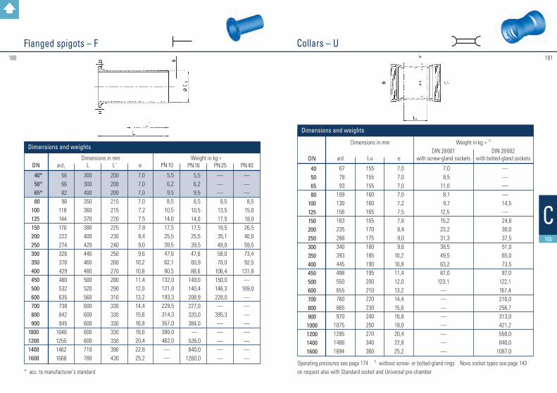
181180
Collars – U Flanged spigots – F
* acc. to manufacturer’s standard Operating pressures see page 174 1) without screw- or bolted-gland rings Novo socket types see page 143 on request also with Standard socket and Universal pre-chamber
DN
40* 50* 65* 80 100 125 150 200 250 300 350 400 450 500 600 700 800 900 1000 1200 1400 1600
ø d1
56 66 82 98 118 144 170 222 274 326 378 429 480 532 635 738 842 945 1048125514621668
L
300300400350360370380400420440460480500520560600600600600600710780
e
7,0 7,0 7,0 7,0 7,2 7,5 7,8 8,4 9,0 9,610,210,811,412,013,214,415,616,818,020,422,825,2
PN 10
5,5 6,2 9,5 8,5 10,5 14,0 17,5 25,5 39,5 47,6 62,1 80,5132,0121,0193,3229,5314,3357,0380,0462,0——
PN 16
5,5 6,2 9,5 8,5 10,5 14,0 17,5 25,5 39,5 47,6 65,9 88,6149,0140,4208,9227,0320,0384,0
—526,0840,0
1260,0
Dimensions in mm Weight in kg ≈
L´
200200200215215220225230240250260270280290310330330330330330390430
PN 25
———
8,5 13,5 17,5 18,5 35,1 49,0 58,0 70,0106,4150,0146,3228,0—
395,3—————
PN 40
———
8,5 15,0 18,0 26,5 40,0 59,5 73,4 92,5131,8—
169,0————————
Dimensions and weights
DN
40 50 65 80100125150200250300350400450500600700800900
1000120014001600
ø d
67 78 93109130156183235288340393445498550655760865970
1075128514881694
Lu
155155155160160165165170175180185190195200210220230240250270340360
DIN 28 601
with screw-gland sockets
7,0 8,5 11,0 8,1 9,7 12,5 15,2 23,2 31,3 38,5 49,5 63,2 87,0123,1
————————
DIN 28 602
with bolted-gland sockets
————
14,5—
24,8 30,0 37,5 51,0 65,0 73,5 97,0122,1167,4216,0256,7313,0421,2558,0840,0
1087,0
e
7,0 7,0 7,0 7,0 7,2 7,5 7,8 8,4 9,0 9,610,210,811,412,013,214,415,616,818,020,422,825,2
Weight in kg ≈ 1) Dimensions in mm
Dimensions and weights
C10b

183182
Double socket bends 90° – MMQ Single socket bends 90° – MQacc. to manufacturer’s standard
Operating pressures see page 174 1) without screw- or bolted-gland ring on request also with Standard socket and Universal pre-chamber
DN
40 50 65 80100125150200250300350400500600700800
L
200 300 370 312 333 374 419 491 583 660 580 625 715 805 9001080
Lu
60,0150,0215,0102,4123,0148,8174,5226,0280,0330,0410,0430,0550,0645,0720,0800,0
with screw-gland
socket
9,5 11,0 15,0 8,0 10,8 16,1 23,8 43,2 70,0 96,0
——————
with bolted-gland
socket
——————————
150,0156,0225,0 325,0482,0651,0
with
TYTON® socket
———
9,0 11,2 18,4 25,4 43,8 76,1 83,2 139,0 186,3 235,4 314,0 473,0 644,5
e
7,0 7,0 7,0 7,0 7,2 7,5 7,8 8,4 9,0 9,610,210,812,013,214,415,6
Weight in kg ≈ 1) Dimensions in mm
Dimensions and weights
Operating pressures see page 174 1) without screw- or bolted-gland rings * acc. to manufacturer’s standardon request also with Standard socket and Universal pre-chamber
DN
40* 50* 65*
80 100 125 150 200 250 300
350* 400* 450* 500* 600* 700* 800* 900* 1000* 1200*
Lu
60,0 150,0 85,0 100,0 125,0 150,0 175,0 225,0 280,0 330,0 410,0 430,0 457,0 550,0 645,0 720,0 800,0 950,01050,01205,0
e
7,0 7,0 7,0 7,0 7,2 7,5 7,8 8,4 9,0 9,6 10,2 10,8 11,4 12,0 13,2 14,4 15,6 16,8 18,0 20,4
with screw-gland
sockets
8,010,514,0 8,610,515,119,231,354,069,8——————————
with
TYTON® sockets
———
8,5 11,0 16,2 20,5 32,4 52,9 72,4 104,8 128,0 208,0 214,4 314,3 480,0 650,0 869,01060,01600,0
with
bolted-gland sockets
————————————
187,0262,0357,0198,0662,0
———
Weight in kg ≈ 1) Dimensions in mm
Dimensions and weights
C10b
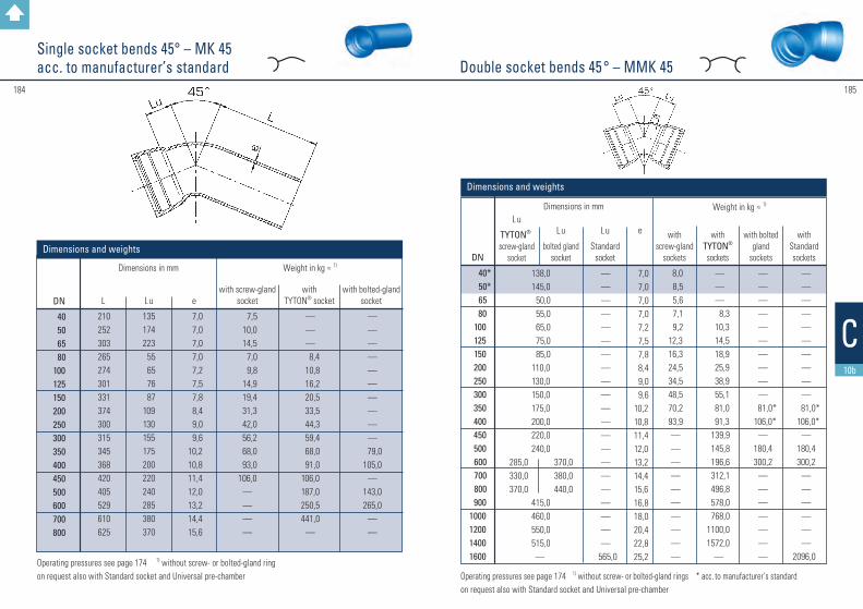
185184
Double socket bends 45 ° – MMK 45Single socket bends 45° – MK 45acc. to manufacturer’s standard
Operating pressures see page 174 1) without screw- or bolted-gland rings * acc. to manufacturer’s standardon request also with Standard socket and Universal pre-chamber
Operating pressures see page 174 1) without screw- or bolted-gland ring on request also with Standard socket and Universal pre-chamber
DN
40 50 65 80100 125 150200250300350
400450500600700800
L
210252303265274301331374300315345368420405529610625
Lu
135174223 55 65 76 87109130155175200220240285380370
with screw-gland
socket
7,5 10,0 14,5 7,0 9,8 14,9 19,4 31,3 42,0 56,2 68,0 93,0106,0
————
with bolted-gland
socket
——————————
79,0105,0
—143,0265,0
——
with
TYTON® socket
———
8,4 10,8 16,2 20,5 33,5 44,3 59,4 68,0 91,0106,0187,0250,5441,0
—
e
7,0 7,0 7,0 7,0 7,2 7,5 7,8 8,4 9,0 9,610,210,811,412,013,214,415,6
Weight in kg ≈ 1) Dimensions in mm
Dimensions and weightsDN
40* 50* 65
80 100 125 150 200 250 300 350 400 450 500
600 700 800
9001000120014001600
Lu
TYTON®
screw-gland socket
e
7,0 7,0 7,0 7,0 7,2 7,5 7,8 8,4 9,0 9,610,210,811,412,013,214,415,616,818,020,422,825,2
with screw-gland
sockets
8,0 8,5 5,6 7,1 9,212,316,324,534,548,570,293,9——————————
with
TYTON® sockets
———
8,3 10,3 14,5 18,9 25,9 38,9 55,1 81,0 91,3 139,9 145,8 196,6 312,1 496,8 578,0 768,0
1100,01572,0
—
with bolted
gland sockets
——————————
81,0* 106,0*
—180,4300,2
———————
with
Standard sockets
——————————
81,0* 106,0*
—180,4300,2
————— —
2096,0
Weight in kg ≈ 1) Dimensions in mm
Dimensions and weights
138,0145,0 50,0 55,0 65,0 75,0 85,0110,0130,0150,0175,0200,0220,0240,0
415,0460,0550,0515,0—
Lu
bolted gland socket
Lu
Standard socket
285,0330,0370,0
370,0380,0440,0
—————————————————————
565,0
C10b

186 187
Operating pressures see page 174 1) without screw- or bolted-gland ring on request also with Standard socket and Universal pre-chamber
DN
40 50 65 80100125150200250300350400500600700800
L
201243298253260283309345270280295308335412480510
Lu
126165218 44 50 57 65 80 95110125140170200250260
with screw-gland socket
7,510,014,5 7,410,114,018,629,236,748,057,071,0————
with bolted-gland socket
——————————
64,0 80,0120,0185,0
——
with
TYTON® socket
———
7,4 10,8 15,1 20,0 30,8 38,9 52,9 56,0 76,5 107,0 178,0 286,0 350,0
e
7,0 7,0 7,0 7,0 7,2 7,5 7,8 8,4 9,0 9,610,210,812,013,214,415,6
Weight in kg ≈ 1) Dimensions in mm
Dimensions and weights
Double socket bends 30° – MMK 30acc. to DIN 28 650
Single socket bends 30° – MK 30acc. to manufacturer’s standard
Operating pressures see page 174 1) without screw- or bolted-gland rings * acc. to manufacturer’s standardon request also with Standard socket and Universal pre-chamber
DN
40* 50* 65*
80 100 125 150 200 250 300 350
400 450*
500 600
700 800 90010001200
103107113 45 50 55 65 80 95110125140255170200
260290320380
e
7,0 7,0 7,0 7,0 7,2 7,5 7,8 8,4 9,0 9,610,210,811,412,013,214,415,616,818,020,4
with screw-gland
sockets
8,0 10,0 13,0 6,8 9,711,615,723,831,345,963,784,8————————
Weight in kg ≈ 1) Dimensions in mm
with TYTON® sockets
———
7,8 9,9 14,3 18,4 23,8 34,6 52,4 74,5 89,1145,0123,7166,9279,0370,0496,0652,0
1020,0
with bolted-gland
sockets
——————————
74,0* 94,0*
—145,5193,0
—————
Dimensions and weights
230 250
Lu
TYTON® screw-gland socket
Lu
bolted-gland socket
C10b

189188
Double socket bends 22 1/2° – MMK 22
Single socket bends 22 1/2° – MK 22acc. to manufacturer’s standard
Operating pressures see page 174 1) without screw- or bolted-gland rings on request also with Standard socket and Universal pre-chamber
DN
40 50 65 80100125150200250300350400500600700800
L
179240232248253274299331260265270278300357420455
Lu
142162152 38 43 49 55 66 75 90100110135155190205
e
7,0 7,0 7,0 7,0 7,2 7,5 7,8 8,4 9,0 9,610,210,812,013,214,415,6
with screw-gland
socket
7,510,012,0 7,0 9,213,517,327,036,047,553,065,0————
with
TYTON® socket
———
8,1 9,7 15,1 18,4 29,2 37,8 50,2 52,0 76,7 97,0163,0336,0460,0
with bolted-gland
socket
——————————
60,0 74,0110,0185,0
——
Dimensions in mm Weight in kg ≈ 1)
Dimensions and weights
Operating pressures see page 174 1) without screw- or bolted-gland rings * acc. to manufacturer’s standardon request also with Standard socket and Universal pre-chamber
DN
40* 50* 65
80 100 125 150 200 250 300 350 400 450 500 600
700 800
9001000120014001600
87,0 90,0 35,0 40,0 45,0 50,0 55,0 65,0 75,0 90,0100,0110,0120,0135,0155,0
195,0220,0240,0285,0
—
e
7,0 7,0 7,0 7,0 7,2 7,5 7,8 8,4 9,0 9,610,210,811,412,013,214,415,616,818,020,422,825,2
with
screw-gland sockets
7,5 9,512,5 4,9 8,611,514,621,030,542,162,174,5——————————
with
TYTON® sockets
———
7,8 9,6 13,5 17,8 22,7 33,5 50,8 67,0 83,2128,0 112,9 154,4 242,0 311,0 422,0 593,0 820,01224,0
—
with
bolted-gland sockets
——————————
70,0* 88,0*
—127,0179,0
———————
with
Standard sockets
—————————————————————
1607,0
Weight in kg ≈ 1) Dimensions in mm
Dimensions and weights
Lu
TYTON®
screw-gland socket
Lu
bolted-gland socket
Lu
Standard socket
175,0
260,0
190,0
—
—————————————————————
280,0
C10b

191190
Double socket bends 11 1/4° – MMK 11
Single socket bends 11 1/4° – MK 11acc. to manufacturer’s standard
Operating pressures see page 174 1) without screw- or bolted-gland ring on request also with Standard socket and Universal pre-chamber
DN
40 50 65 80100125150200250300350400500600700800
L
175171187240243261284311255260235238250287340375
Lu
83131 67 30 33 36 40 46 50 60 65 70 85 95110125
with screw-gland
socket
6,5 8,511,5 7,1 9,212,416,724,833,544,047,056,0————
with bolted-gland socket
——————————
54,0 65,0 95,0 185,0 258,0 292,0
with
TYTON® socket
— — —
7,6 9,8 14,0 18,0 27,0 37,8 47,0 46,0 66,9 83,2 163,0 249,0 286,0
e
7,0 7,0 7,0 7,0 7,2 7,5 7,8 8,4 9,0 9,610,210,812,013,214,415,6
Weight in kg ≈ 1) Dimensions in mm
Dimensions and weights
Operating pressures see page 174 1) without screw- or bolted-gland rings * acc. to manufacturer’s standard on request also with Standard socket and Universal pre-chamber
DN
40* 50* 65
80 100 125 150 200 250 300 350 400 450 500 600
700 800 9001000120014001600
63,0 65,0 25,0 30,0 35,0 35,0 40,0 45,0 50,0 60,0 65,0 70,0 70,0 85,0 95,0
110,0 120,0 130,0150,0
—
e
7,0 7,0 7,0 7,0 7,2 7,5 7,8 8,4 9,0 9,6 10,2 10,8 11,4 12,0 13,2 14,4 15,6 16,8 18,0 20,4 22,8 25,2
with screw-gland
sockets
7,0 9,011,5 6,5 8,110,613,420,528,138,349,767,5——————————
with
TYTON® sockets
7,6 8,6 13,0 16,7 21,1 30,2 45,4 62,1 73,4 92,5 86,4 125,3 201,0 294,3 350,0 506,0 650,01078,0
—
with
bolted-gland sockets
———————
64,0* 79,0*
—120,5 158,0 164,0 283,0
—————
with
Standard sockets
——————————————————
1416,0
Weight in kg ≈ 1) Dimensions in mm
Dimensions and weights
Lu
TYTON®
screw-gland socket
Lu
bolted-gland socket
Lu
Standard socket
95,0
160,0
110,0
—
—————————————————————
175,0
C10b

193192
➜
Double socket tees with flanged branch – MMA
Operating pressures see page 174 1) without screw- or bolted-gland ring * acc. manufacturer’s standardon request also with Standard socket and Universal pre-chamber
DN 1
40* 50*
65*
DN 2
404050405065
Lu
155170170190190190
l u
140150150165165165
e1
7,0 7,0 7,0 7,0 7,0 7,0
e2
7,0 7,0 7,0 7,0 7,0 7,0
with screw-gland
sockets
10,512,513,516,016,518,0
with bolted-gland
sockets
——————
with
TYTON® sockets
——————
Weight in kg ≈ 1) Dimensions in mm
Dimensions and weights
Operating pressures see page 174 1) without screw rings * acc. manufacturer’s standard on request also with Standard socket and Universal pre-chamber
➜
DN 1
80
100
125
150
200
DN 2
40* 50* 65*
80 40* 50* 65* 80*
100 40* 50* 80*
100 125
40* 50* 80*
100 125*
150 40* 50* 80*
100 125*
150 200
Lu
170170170170190190190190190195195195195225195195195195255255200200200200 255 255 315
l u
155160160165170170175175180185185190195200195200205210220220230230235240250250260
e2
7,07,07,07,07,07,07,07,07,27,07,07,07,27,57,07,07,07,27,57,87,07,07,07,27,57,88,4
e1
7,0
7,2
7,5
7,8
8,4
with screw-gland
sockets
11,813,012,515,113,014,015,016,217,417,317,518,920,522,121,622,723,824,828,030,827,830,031,332,437,038,946,4
with bolted-gland
sockets
———————————————————————————
Weight in kg ≈ 1) Dimensions in mm
with TYTON® sockets
13,013,013,514,014,915,716,917,518,619,420,021,622,724,323,824,325,927,031,332,930,831,332,934,041,043,249,7
C10b

195194
Double socket tees with flanged branch – MMA
Operating pressures see page 174 1) without screw rings * acc. to manufacturer’s standardon request also with Standard socket and Universal pre-chamber
Operating pressures see page 174 1) without screw rings * acc. to manufacturer’s standardon request also with Standard socket and Universal pre-chamber
➜➜
DN 1
250
300
350
400
DN 2
40* 80*
100150 200 250
80*100150 200
250* 300
80*100
150* 200
250* 300*
350 80*
100150 200
250* 300
350* 400
Lu
200200200260 315 375205205260320430435205205325325495495495210210270325440440560560
lu
265265270280290300295300310320330340325330340350360370380355360370380390400415420
e1
9,0
9,6
10,2
10,8
e2
7,0 7,0 7,2 7,8 8,4 9,0 7,0 7,2 7,8 8,4 9,0 9,6 7,0 7,2 7,8 8,4 9,0 9,610,2 7,0 7,2 7,8 8,4 9,0 9,6 10,2 10,8
with screw-gland
sockets
36,0 40,0 42,0 52,4 53,5 62,5 51,8 52,9 65,9 72,4 89,0 90,7 63,0 62,0 82,0 89,5101,0114,0 122,0 79,9 81,0 93,4 109,0 118,5 125,5150,0172,0
with bolted-gland
sockets
———————————————————————————
with
TYTON® sockets
45,4 48,0 48,1 56,2 60,5 75,6 58,9 60,5 70,7 70,0 91,8 95,6 73,4 73,4 89,1 97,2 98,0114,0125,0 92,9 94,0105,8113,9115,0132,3150,0177,0
Weight in kg ≈ 1) Dimensions in mm
DN 1
400*
450*
500
DN 2
80100150 200 300 400 80 100 150 200 250 300 350 400 450
80*100150200
300*400500
Lu
210210270325440560215215270300450450560560620215215330330450565680
lu
355360370380400420390390400410420430450450460415420430440460480500
e1
10,8
11,4
12,0
e2
7,0 7,2 7,8 8,4 9,6 10,8 7,0 7,2 7,8 8,4 9,0 9,6 10,2 10,8 11,4 7,0 7,2 7,8 8,4 9,6 10,8 12,0
with screw-gland
sockets
——————————————————————
with bolted-gland
sockets
94,0 95,0104,0114,0139,0169,0
—————————
110,7110,7130,0140,4174,4220,0244,0
with
TYTON® sockets
——————
110,0110,0128,0132,0145,5161,5226,0236,0267,0103,0104,0138,0140,0156,0193,0236,0
Weight in kg ≈ 1) Dimensions in mm
C10b

196 197
Double socket tees with flanged branch – MMA
Operating pressures see page 174 1) without screw rings * acc. to manufacturer’s standardon request also with Standard socket and Universal pre-chamber
Operating pressures see page 174 1) without screw rings * acc. manufacturer’s standardon request also with Standard socket and Universal pre-chamber
l➜
DN 1
600
700
800
DN 2
80* 100* 150*
200 300*
400 500*
600 80* 100* 150*
200 250* 300* 350*
400 500* 600*
700 80* 100* 150*
200 250* 300* 350*
400 500*
600800
Lu
340340340340460570800800345345345345575575575575925925925350
350 350 350 580 580 580 580 1045 1045 1045
lu
475470480500520540550580510510520525535540555555570585600570570580585590600615615630645 675
e1
13,2
14,4
15,6
e2
7,0 7,2 7,8 8,4 9,6 10,8 12,0 13,2 7,0 7,2 7,8 8,4 9,0 9,610,210,812,013,214,4 7,0 7,2 7,8 8,4 9,0 9,6 10,2 10,8 12,0 13,2 15,6
with screw-gland
sockets
——————————————————————————————
with bolted-gland
sockets
182,5183,6189,0187,6233,8257,0 336,0386,0266,0278,0263,0262,0287,0381,0 279,0392,0482,0523,0563,0319,0339,9322,9298,0433,0408,2435,0430,0686,0686,0755,0
with TYTON® sockets
169,0170,0174,0178,0210,0245,0330,0339,0248,0260,0263,0266,0269,0340,0261,0374,0464,0505,0545,0307,0324,0332,0342,0415,0431,0423,0437,0628,0640,0743,0
Weight in kg ≈ 1) Dimensions in mm
DN 1
900
1000
1200
1400
1600
DN 2
80* 100* 150*
200 250* 300*
400600
700*900
150*200
250* 300*
400600
800*1000 200* 400* 500*
600 700*
800 900*1000600800
1000600800
10001200
Lu
355
590
1170
360360380595595
129012901290840840840840
10701070130013001030126014951040127515051740
lu
630635640645645660675705720750700705710720735765825825835835850885900915930945980
101010401090112011501180
e1
16,8
18,0
20,4
22,8
25,2
e2
7,0 7,2 7,8 8,4 9,0 9,6 10,8 13,2 14,4 16,8 7,8 8,4 9,0 9,6 10,8 13,2 15,6 18,0 8,4 10,8 12,0 13,2 14,4 15,6 16,8 18,0 13,2 15,6 18,0 13,2 15,6 18,0 20,4
with screw-gland
sockets
—————————————
——
——————— —————
2130,02359,02643,02938,0
with bolted-gland
sockets
—————————————
——
————————————————
with
TYTON® sockets
400,0470,0472,0540,0
—561,0572,0820,0868,0898,0650,0561,0 691,0 625,0644,01162,0 1018,0 1248,0 949,0 960,0 969,0 985,01135,01160,01296,01428,01655,01850,0 2100,0
————
Weight in kg ≈ 1) Dimensions in mm
C10b

198
All socket tees – MMB
Operating pressures see page 174 1) without screw rings * acc. to manufacturer’s standardon request also with Standard socket and Universal pre-chamber
Operating pressures see page 174 1) without screw rings * acc. to manufacturer’s standardon request also with Standard socket and Universal pre-chamber
➜
DN 1
40* 50*
65*
80
100
125
DN 2
40 40
50* 40 50
65* 40* 50* 65*
80 40* 50* 65* 80*
100 40* 50* 80*
100 125
Lu
156170170190190190170170170170190190190190190195195195195225
lu
78 83 85 90 92 95 80 80 80 85 90 90 90 95 95100105105110110
e1
7,0 7,0
7,0
7,0
7,0 7,2
7,5
e2
7,0 7,0 7,0 7,0 7,0 7,0 7,0
7,0 7,0 7,0 7,0 7,0 7,27,07,0 7,07,27,5
with screw-gland
sockets
11,012,513,516,017,018,010,110,511,013,011,712,513,014,614,916,216,516,618,119,4
with
TYTON® sockets
——————
10,811,9—
14,014,015,113,015,117,018,418,520,521,623,2
with
Standard sockets
————————————————————
Weight in kg ≈ 1) Dimensions in mm
Dimensions and weights
➜
DN 1
150
200
250*
300*
DN 2
40* 50* 80*
100 125* 150
40* 50*
65 80 100
125* 150 200 80 100 125 150 200 250 50 65 80 100 125 150 200 250 300
Lu
195195195195255255200200200200200255255315200200200260315375205205205205205320320430430
lu
115115120120125125140140140145145145150155170175175180185190195195195200200200205210215
e1
7,8
8,4
9,0
9,6
e2
7,0 7,0 7,0 7,2 7,5 7,8 7,0 7,0 7,0 8,1 8,4 8,8 9,1 9,8 7,0 7,2 7,5 7,8 8,4 9,0 7,0 7,0 7,0 7,2 7,5 7,8 8,4 9,0 9,6
with screw-gland
sockets
19,4 20,0 22,7 22,7 25,0 27,0 25,5 26,5 28,0 30,8 31,9 35,0 37,8 40,0 38,0 38,9 43,0 44,5 51,5 61,0 44,0 44,5 50,0 47,0 55,0 59,4 61,0 74,0 81,0
with
TYTON® sockets
22,7 22,5 24,8 25,4 30,2 30,8 30,2 31,3 28,0 38,4 31,9 37,8 42,1 45,9 45,4 46,4 46,4 51,8 56,2 65,9 44,0 44,5 56,7 58,3 58,4 62,4 66,4 82,1 92,1
with
Standard sockets
—————————————————————————————
Weight in kg ≈ 1) Dimensions in mm
C10b
199

201200
➜
DN 1
600*
700*
800*
900*
DN 2
125150200250300350400500600150200250300400500
6002)
700125300400500600700800500600900
Lu
3403403404604605705708008003453455755755759259259253505805801045104510451045117011701170
lu
345345365365365375380390400395400410415425435430455475470480490500510510535540610
e1
13,2
14,4
15,6
16,8
e2
7,5 7,8 8,4 9,0 9,610,210,812,013,2 7,8 8,4 9,0 9,6 10,8 12,0 13,2 14,4 7,5 9,6 10,812,013,2 14,4 15,6 12,0 13,2 16,8
with screw-gland
sockets
———————————————————————————
with
TYTON® sockets
189,0 197,0 205,0 222,0 231,0 236,0 245,0 325,0 340,0253,0264,0275,0370,0355,0445,0545,0497,0408,0490,0520,0528,0760,0805,0820,0500,0525,0850,0
with
Standard sockets
———————————————————————————
Weight in kg ≈ 1) Dimensions in mm
All socket tees – MMB
Operating pressures see page 174 1) without screw rings * acc. to manufacturer’s standardon request also with Standard socket and Universal pre-chamber
Operating pressures see page 174 1) without screw rings * acc. to manufacturer’s standardon request also with Standard socket and Universal pre-chamber
➜
DN 1
350*
400*
450*
500*
DN 2
80100200250300350 8010015020025030040080100150200250300350400450 80100125150200250300350400500
Lu
205205325495495495210210270440440440560 215 215 330 330 450 450 560 560 620 215 215 215 330 330 450 450 565 565 680
lu
220220240245250260245245250260265270285 270 270 280 280 290 290 305 320 380 295 295 295 305 305 315 320 330 335 350
e1
10,2
10,8
11,4
12,0
e2
7,0 7,2 8,4 10,5 9,6 10,2 7,0 7,2 7,8 8,4 9,0 9,6 10,8 7,0 7,2 7,8 8,4 9,0 9,610,210,811,4 7,0 7,2 7,5 7,8 8,4 9,0 9,6 10,2 10,8 12,0
with screw-gland
sockets
74,0 79,0 91,0 103,0 115,0 128,0 83,5 86,5 94,0 100,0 108,0 122,0 145,0
———————————————————
with
TYTON® sockets
74,0 79,0 88,0 118,8 126,4 125,0 95,5 93,4 94,0 111,8 118,8 123,7 175,5 110,0 110,0 128,0 146,5 155,0 162,5 174,0 180,0 185,0 128,0 131,0 134,0 136,0 145,0 155,0 170,0 183,0 195,0 233,3
with
Standard sockets
————————————————————————————————
Weight in kg ≈ 1) Dimensions in mm
C10b

202 203
All socket tees – MMB
Operating pressures see page 174 1) without screw rings * acc. to manufacturer’s standardon request also with Standard socket and Universal pre-chamber
➜
Double socket tapers – MMR
Operating pressures see page 174 1) without screw rings * acc. to manufacturer’s standardon request also with Standard socket and Universal pre-chamber
DN 1
50* 65*
80
100
DN 2
404050
40*50
65* 40* 50* 65*
80
Lu
200200200200110200150150120 90
e1
7,0 7,0
7,0
7,2
e2
7,07,07,07,07,07,07,07,07,07,0
with screw-gland
sockets
7,8 7,810,513,5 5,415,214,0 7,6 7,0 8,1
with
TYTON® sockets
— — — — — — — — — 9,2
Dimensions and weights
Weight in kg ≈ 1) Dimensions in mm
l
DN 1
1000*
1200*
1400*
1600*
DN 2
150200250300400600800900
1000300600700800900
1200600800900
100012001400600800900
1000120014001600
Lu
360 360 595 595 5951290129012901290 840 84010701070130015251030126014951975172519601040127512601505174019702200
lu
570580590600600640660680680730750750760760760840865875885905930940965975985
101010301050
e1
18,0
20,4
22,8
25,2
e2
7,8 8,4 9,0 9,610,813,215,616,818,0 9,613,214,415,616,820,413,215,616,818,020,422,813,215,616,818,020,422,825,2
with screw-gland
sockets
————————————————————————————
with
TYTON® sockets
507,0 508,0 597,0 613,0 619,01028,01102,01108,01115,0 940,0 980,01140,01150,01285,01536,01770,01990,02120,02140,02360,03000,0
———————
with
Standard sockets
—————————————————————
2150,02450,02520,02650,02950,03400,03900,0
Weight in kg ≈ 1) Dimensions in mm
C10b

204
Double socket tapers – MMR
Operating pressures see page 174 1) without screw rings * acc. to manufacturer’s standardon request also with Standard socket and Universal pre-chamber
Operating pressures see page 174 1) without screw rings * acc. to manufacturer’s standardon request also with Standard socket and Universal pre-chamber
➜
DN 1
125
150
175200
250
300
350
DN 2
65* 80100 65 80100125150 80100125150175 80100125150200 80100150200250150200250300
Lu
170140100180190150100200280250200150200300300300250150300300350250150500360260160
e1
7,5
7,8
8,18,4
9,0
9,6
10,2
e2
7,0 7,0 7,2 7,0 7,0 7,2 7,5 7,8 7,0 7,2 7,5 7,8 8,1 7,0 7,2 7,5 7,8 8,4 7,0 7,2 7,8 8,4 9,0 7,8 8,4 9,0 9,6
with screw-gland
sockets
9,6 9,9 9,814,012,313,412,636,525,918,317,517,830,033,029,026,528,030,229,555,141,037,836,778,048,047,045,0
with
TYTON® sockets
— 11,311,813,015,115,715,7—
22,720,522,722,1—
33,029,031,334,634,629,536,250,243,243,778,048,047,045,0
Weight in kg ≈ 1)Dimensions in mm
l
DN 1
400
450
500
600
700
800
900
1000
120014001600
DN 2
200250300350300
350*400250300
350* 400*
450300350
400* 500*
400 500* 600*
500600700700800
600*800900
10001200
1200*1400
Lu
400360260160500500160500500500500500500600460500500500500500480280480280880480280480360560360
e1
10,8
11,4
12,0
13,2
14,4
15,6
16,8
18,0
20,422,825,2
e2
8,4 9,0 9,610,2 9,610,210,8 9,0 9,610,210,812,0 9,610,210,812,010,812,013,212,013,214,414,415,613,215,616,818,020,420,422,8
with screw-gland
sockets
79,9 73,5 68,0 70,0139,3129,0156,6101,0133,0150,0139,5267,0
——————————————— ————
with
TYTON® sockets
65,0 73,5 68,0 70,0120,0129,0 75,0127,4134,0143,6150,7155,0157,0184,0185,8186,8
296,0341,5252,5275,0288,0296,0382,0347,0476,0460,0420,0652,0880,0
1200,01260,0
Dimensions in mm Weight in kg ≈ 1) 205
C10b

207206
l➜
Single socket tees with flanged branch – Aacc. to manufacturer’s standard
Operating pressures see page 174 1) without screw ringon request also with Standard socket and Universal pre-chamber
DN 1
40 50
80
100
DN 2
40 40 50 40 50 80 40 50 65 80 100
Lu
400400400400400400400400400400400
l
150150150180180180200200200200200
z
78 85 85106106106120120120120120
e1
7,07,0
7,0
7,2
e2
7,07,0
7,0
7,07,07,07,07,2
with screw- gland socket
10,010,512,012,313,015,115,715,516,017,818,7
with
TYTON® socket
———12,313,015,716,215,516,018,418,8
Weight in kg ≈ 1) Dimensions in mm
Dimensions and weights
Operating pressures see page 174 1) without screw ringon request also with Standard socket and Universal pre-chamber
DN 1
125
150
200
300
4001000
DN 2
40 50 80 100 125 40 50 80 100 125 150 50 80 100 150 200 80 100 150 400600
Lu
425 425 425 425 425 450 450 450 450 450 450 600 600 600 600 600 800 800 80010001770
l
190190190195200205205205210210210240240250275300300300300450825
z
112112112112112128128128128128128190190190240240260260260330645
e1
7,5
7,8
8,4
9,6
10,818,0
e2
7,0 7,0 7,0 7,2 7,5 7,0 7,0 7,0 7,2 7,5 7,8 7,0 7,0 7,2 7,8 8,4 7,0 7,2 7,810,812,0
with screw- gland socket
17,5 18,0 20,0 21,6 26,0 24,8 24,0 26,4 25,0 28,5 30,4 46,0 50,0 55,0 58,0 64,8119,5121,0126,5186,0—
with
TYTON® socket
17,5 18,0 22,5 23,5 26,0 23,0 24,0 28,0 29,2 28,5 30,4 46,0 55,0 51,0 58,0 60,0 119,5 121,0 126,5 186,01160,0
Weight in kg ≈ 1) Dimensions in mm
C10b

209208
Double flanged bends 90° – Q
Single socket tees with socket branch – Bacc. to manufacturer’s standard
Operating pressures see page 174 1) without screw ringson request also with Standard socket and Universal pre-chamber * acc. to manufacturer’s standard
DN
40* 50* 65*
80 100 125 150 200 250 300 350 400 450 500 600 700 800 9001000120014001600
L
140 150 165 165 180 200 220 260 350 400 450 500 550 600 700 800 90010001100130013501450
e
7,0 7,0 7,0 7,0 7,2 7,5 7,8 8,4 9,0 9,610,210,811,412,013,214,415,616,818,020,422,825,2
PN 10
5,5 7,5 10,2 10,2 12,9 18,9 29,3 36,2 58,3 82,1 102,1 144,7 234,0 266,0 370,0 539,0 774,0 745,01010,0
———
PN 16
5,5 7,5 10,2 10,2 12,9 22,0 29,2 36,2 58,3 82,1 111,2 157,7 234,0 277,5 404,0 420,0 720,0 836,01099,01463,02150,02970,0
PN 25
5,5 7,5 10,2 11,0 12,9 22,0 33,5 45,9 81,0116,6155,0217,0241,0305,0346,0575,0672,0—————
PN 40
5,5 7,5 10,2 11,0 12,9 23,2 33,5 53,0101,0144,2199,0284,0308,0375,0458,0———————
Weight in kg ≈ Dimensions in mm
Dimensions and weights
DN 1
100150200
DN 2
80 80 80
Lu
910905900
lu
95120 145
z
410405400
a
e1
7,27,88,4
27,040,055,0
Weight in kg ≈ with Novo sockets
Dimensions in mm
e2
7,07,07,0
Dimensions and weights – B long version
DN 1
40 80100
150
DN 2
40 80 80100 80100125
Lu
400400400400450450450
lu
105 86 95 95120120125
z
132106120120128128128
a
e1
7,07,07,2
7,8
8,514,015,016,0 25,0 45,0 28,0
Weight in kg ≈ 1) Dimensions in mm
e2
7,07,07,07,27,07,27,5
Dimensions and weights – B
C10b

211210
Double flanged bends 45° – FFK 45Double flanged duckfoot bends 90° – N
DN
40* 50* 65*
80 100 125 150 200 250 300 350 400 450 500 600
700* 800*
90010001200
L
—150165165180200220260350400450500550600700800900
100011001300
c
— 90 99110125140160190225255290320355385450480540645710845
PN 10
10,5 10,5 16,0 15,7 18,9 27,0 34,6 55,6 84,0 117,7 137,0 263,5
— 374,8 538,9 752,0 926,0——
2311,0
PN 16
10,5 10,5 16,0 15,7 18,9 27,0 38,9 55,6 84,0 117,7 142,0 248,0 295,0 311,0 482,0 705,0 970,0
—1626,0
—
PN 25
10,5 10,5 16,0 15,7 25,4 22,7 31,0 48,5 80,5 114,0 154,8 209,0 309,0 335,0 506,0 769,0 1086,0
———
PN 40
10,5 10,5 16,0 15,7 25,4 23,9 35,5 60,0 101,0 145,0 201,0 277,0 395,0 402,0 612,0
—————
d
— 150165180200225250300350400450500550600700800900
100010001300
e
— 7,0 7,0 7,0 7,2 7,5 7,8 8,4 9,0 9,6 10,2 10,8 11,4 12,0 13,2 16,0 19,016,818,020,4
Weight in kg ≈Dimensions in mm
Dimensions and weights
* ac
c. to
man
ufac
ture
r’s st
anda
rd
Base borehole on request. * acc. to manufacturer’s standard
350* 400* 500*
215243290
10,511,012,0
64,0 85,0129,0
69,094,5157
85,5114,5178,0
115,5184,5246,0
Short length acc. to manufacturer’s standard
DN
40* 50* 65*
80 100 125 150 200 250 300 350 400 450 500 600 700 800 900100012001400
L
140150165130140150160180350400298324350375426478529581632750775
e
7,0 7,0 7,0 7,0 7,2 7,5 7,8 8,4 9,0 9,610,210,811,412,013,214,415,616,818,020,422,8
PN 10
7,0 9,0 12,0 10,3 12,6 17,5 21,6 32,4 60,9 90,2 96,1 117,2 150,0 185,8 288,0 489,0 403,0
— 727,9
——
PN 16
7,0 9,0 12,0 10,3 12,6 17,5 21,6 32,4 60,9 90,2 102,6129,1 150,0 235,4 347,0 481,0 442,0480,0 685,0
1251,01626,0
PN 25
7,0 9,0 12,0 10,3 —
17,5 33,0 34,0 101,0 87,5 111,0 191,3 180,0 259,2 292,0 392,0 535,0
—1099,0
——
PN 40
7,0 9,0 12,0 10,3 —
18,3 24,5 41,5 83,0 118,0 141,0 196,0248,0264,0397,0
——————
Weight in kg ≈ Dimensions in mm
Dimensions and weights
C10b

213212
Double flanged bends 22 1/2 ° – FFK 22acc. to manufacturer’s standard
Double flanged bends 30° – FFK 30acc. to manufacturer’s standard
DN
40 50 65 80 100 125 150 200 250 300 350 400 450 500 600 700 800 90010001200
L
140150165130140150160180 210255165183255220309346383420455530
e
7,0 7,0 7,0 7,0 7,2 7,5 7,8 8,4 9,0 9,510,210,811,412,013,214,415,616,818,020,4
PN 10
7,0 9,0 12,0 10,0 13,7 15,7 22,7 35,1 47,5 68,0 70,2 85,9143,0129,5230,0360,0439,6
———
PN 16
7,0 9,0 12,0 10,0 13,7 15,7 22,7 35,1 44,0 68,0 71,0 82,5153,0157,5289,0386,0529,0
———
PN 25
7,0 9,0 12,0 10,0
— 18,0 22,0 33,0 90,0 73,0 88,0 104,5 183,0 205,0 289,0 416,0 623,0
—1018,0
—
PN 40
7,0 9,0 12,0 10,0
— 21,0 25,0 42,0 65,0 100,0 142,0 172,5 251,0275,0298,0
—————
Weight in kg ≈ Dimensions in mm
Dimensions and weights DN
40 50 65 80 100 125 150 200 250 300 350 400 450 500 600 700 800 9001000120014001600
L
140150165130140150160180210255140153209185254284314375410467520560
e
7,0 7,0 7,0 7,0 7,2 7,5 7,8 8,4 9,0 9,610,210,811,412,013,214,415,616,818,020,422,825,2
PN 10
7,0 9,0 12,0 10,7 13,6 17,2 22,1 34,6 48,6 68,6 63,7 80,5 135,0 125,8 203,0 327,0418,0
—575,0
———
PN 16
7,0 9,0 12,0 10,7 13,6 17,2 22,1 34,6 48,6 68,6 64,8 95,6 145,0 137,0245,0360,0448,0
—655,0850,0
1278,01805,0
PN 25
7,0 9,0 12,0 10,7
— 29,0 22,0 33,5 48,5 72,0 78,0 97,5 183,0 175,0 247,0 369,0 558,0
—————
PN 40
7,0 9,0 12,0 10,7—
21,0 25,0 42,5 65,5 99,0 132,0 165,5 251,0 345,0 268,0
———————
Weight in kg ≈ Dimensions in mm
Dimensions and weights
C10b

215214
All flanged tees – TDouble flanged bends 11 1/4 ° – FFK 11acc. to manufacturer’s standard
* acc. to manufacturer’s standard
➜
DN 1
40 50
65
80
100
125
DN 2
40 40 50 40 50 65
40* 50 65 80
40* 50 65 80 100
40* 50* 65 80 100 125
L
280300
330
330
360
400
l
140145150153158165155160160165170170170175180185185185190195200
e1
7,0 7,0
7,0
7,0
7,2
7,5
e2
7,0 7,0 7,0 7,0 7,0 7,0 7,0 7,0 7,0 7,0 7,0 7,0 7,0 7,0 7,2 7,0 7,0 7,0 7,0 7,2 7,5
PN 10
10,512,012,515,015,516,514,715,716,417,017,818,719,420,221,3 23,8 24,3 24,8 25,4 27,0 28,1
PN 16
— — — — — —14,715,716,417,017,818,719,420,221,3 23,8 24,3 24,8 25,4 27,0 28,1
PN 25
— — — — — —14,715,716,417,017,222,720,424,522,0 22,5 23,0 24,0 30,0 26,0 32,5
PN 40
— — — — — —14,715,716,417,017,222,718,624,5 22,0 24,0 24,5 25,5 26,0 28,5 31,0
Weight in kg ≈Dimensions in mm
Dimensions and weights
DN
40 50 65 80 100 125 150 200 250 300 350 400 450 500 600 700 800 9001000120014001600
L
140150165130140150160180210255105113144135 174 194213280310346405405
e
7,0 7,0 7,0 7,0 7,2 7,5 7,8 8,4 9,0 9,610,210,811,412,013,214,415,616,818,020,422,825,2
PN 10
7,0 9,0 12,0 10,6 13,7 17,2 23,2 34,6 47,0 69,1 57,2 71,8 108,0106,9 170,0265,0321,8
—588,0
———
PN 16
7,0 9,0 12,0 10,6 13,7 17,2 23,2 34,6 47,0 69,1 53,0 72,5 118,0 140,8222,5292,0396,0397,5656,0870,0
1111,01520,0
PN 25
7,0 9,0 12,0 10,6
— 18,0 22,0 54,5 48,0 69,5 70,0 89,5 145,0 137,0 229,0 370,0490,0
—722,0
———
PN 40
7,0 9,0 12,0 10,6
— 21,0 25,0 39,0 65,0 96,5 138,5 168,5 213,5 237,5 260,5
———————
Weight in kg ≈Dimensions in mm
Dimensions and weights
C10b

217216Weight in kg ≈
➜➜
All flanged tees – T
* acc. to manufacturer’s standard
DN 1
150
175
200
250
300
DN 2
40 50*
65 80 100 125 150 80 100 150 40 50 65 80 100 125 150 200 50 65
80* 100 125
150* 200 250 40 50 65
80* 100 125
150* 200
250* 300
L
440
550
520
700
800
l
195200200205210215220215220230220225230235240245250260255260265275280300325350275280285290300305325350375400
e1
7,8
8,1
8,4
9,0
9,6
e2
7,0 7,0 7,0 7,0 7,2 7,5 7,8 7,0 7,2 7,8 7,0 7,0 7,0 7,0 7,2 7,5 7,8 8,4 7,0 7,0 7,0 7,2 7,5 7,8 8,4 9,0 7,0 7,0 7,0 7,0 7,2 7,5 7,8 8,4 9,0 9,6
PN 10
29,7 30,8 31,3 31,9 32,4 34,6 32,2 58,0 60,0 64,0 45,4 45,4 45,4 47,4 47,5 50,0 51,3 51,8 68,0 64,0 74,0 75,0 75,0 78,3 88,7 91,8 95,5 96,0 97,0 120,6104,2 113,0 108,0 114,0 121,0 131,0
PN 16
29,7 30,8 31,3 31,9 32,4 34,6 36,2 58,0 60,0 64,0 45,4 45,4 45,4 47,4 47,5 50,0 51,3 51,8 68,0 64,0 74,0 75,0 75,0 78,3 88,7 91,8 95,5 96,0 97,0 120,6104,2 103,0 108,0 114,0 121,0 131,0
PN 25
29,0 35,5 30,5 41,6 42,1 33,5 49,1 — — —
56,5 61,5 64,0 57,5 58,5 61,0 54,0 77,5 97,0 69,0 78,0103,0 75,5110,7 94,0 121,0105,5106,0107,0108,0158,0111,0116,0130,0129,0194,0
PN 40
33,0 40,0 34,5 45,9 35,5 38,0 58,3 — — —
68,5 73,5 74,0 68,5 75,1 73,0 80,0 94,0 97,0 89,0114,0123,1 95,5 128,5 119,0 130,0139,5140,0141,0142,0143,0145,0179,5164,0174,0188,0
Dimensions in mm
* acc. to manufacturer’s standard
DN 1
350
400
450
DN 2
65 80 100 125 150 200 250 300 350
80* 100 125
150* 200
250* 300*
350 400 80 100 150 200 250 300 350 400 450
L
850
900
950
l
315320325325325325325425425350350350350350350450450450375375375375375375475475475
e1
10,2
10,8
11,4
e2
7,0 7,0 7,2 7,5 7,8 8,4 9,0 9,6 10,2 7,0 7,2 7,5 7,8 8,4 9,0 9,6 10,2 10,8 7,0 7,2 7,8 8,4 9,0 9,6 10,2 10,8 11,4
PN 10
124,0 131,2 130,1 131,8 135,0 137,7 137,7 154,4 150,6 167,4 170,6 171,2 157,0 192,2 185,8 196,0 198,2 198,5 230,0 249,5 232,0 242,0 248,0 282,0 290,0 292,0 313,0
PN 16
120,0 128,0 140,4 129,0 150,1 149,0 145,0 151,5 151,0 180,4 185,8 170,5 169,0 192,2 185,8 200,3 223,6 225,0 243,0 244,0 265,0 258,0 269,0 282,0 309,0 312,0 347,0
PN 25
136,0167,4173,0145,0147,0160,0162,0172,0192,0186,0187,0192,0192,0213,8207,0228,0240,0254,0—————————
PN 40
180,0181,0183,0189,0202,0210,0216,0222,0249,0253,0254,0258,0262,0277,0283,0308,0330,0356,0—————————
Dimensions in mm Weight in kg ≈
C10b
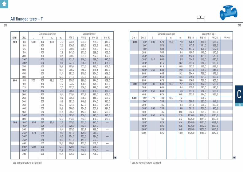
219218
➜➜
All flanged tees – T
* acc. to manufacturer’s standard * acc. to manufacturer’s standard
DN 1
500
600
700
DN 2
80 100 125 150 200
250* 300*
350 400 450 500 80 100 125
150* 200 250 300 350 400 450
500* 600
100* 150*200
250* 300* 350*400
500* 600*700
L
1000
1100
650
870
1200
l
400400400400400400500500500500500450450450450450450550550550550550550525525525555555555555600600600
e1
12,0
13,2
14,4
e2
7,0 7,2 7,5 7,8 8,4 9,0 9,6 10,2 10,8 11,4 12,0 7,0 7,2 7,5 7,8 8,4 9,0 9,6 10,2 10,8 11,4 12,0 13,2 7,2 7,8 8,4 9,0 9,6 10,2 10,8 12,0 13,2 14,4
PN 10
233,5236,5250,6243,5260,3271,1277,0295,4286,2282,0311,0 358,0373,7307,0386,6319,4395,8392,0374,0380,0385,0395,0413,0325,0326,0355,3401,0404,0411,0490,9570,8572,4635,0
PN 16
234,0265,0260,0273,5291,6278,0285,0303,0346,7319,0317,5389,0408,5356,0388,0417,9386,0440,6427,0434,0443,0460,0513,0351,0352,0393,1429,0432,0441,0467,0563,0658,8622,0
PN 25
281,0305,6285,0288,0292,0298,0305,0325,0356,4354,0356,6374,0375,0378,0380,0410,0416,0444,0460,0507,1476,0493,0480,0473,0474,0486,0519,0524,0537,0566,0675,0704,0726,0
PN 40
348,0349,0353,0362,0362,0370,0391,0408,0447,0458,0469,0468,0469,0473,0476,0502,0508,0530,0574,0594,0609,0623,0659,0
——————————
Weight in kg ≈Dimensions in mm
DN 1
800
900
1000
DN 2
80* 100* 150* 200
250* 300* 350*
400 500*
600 700*
800 100*
200 300*
400 100* 150* 200
300* 400
500* 600
700* 800* 900*
1000
L
690
910
1350
730
950
770
990
1650
l
570570580585585600615615630645650675640645660675700705705735735825765825825825825
e1
15,6
16,8
18,0
e2
7,0 7,2 7,8 8,4 9,0 9,6 10,2 10,8 12,0 13,2 14,4 15,6 7,2 8,4 9,610,8 7,2 7,8 8,4 9,610,812,013,214,415,616,818,0
PN 10
426,5 417,5 457,2 468,7 443,0 574,6 514,0 583,2 737,6 694,4 719,0 756,0 702,0 455,0 544,0 552,0
588,0 591,0 681,0 693,01010,01025,01048,01075,01095,01125,0
PN 16
464,5 471,0 428,0 475,0 481,0 545,0 556,0 580,0 738,0 769,0 771,0 760,0 472,0 477,0 566,0 574,0 635,0 667,0 670,0 760,0 774,01114,01141,01161,01182,01207,01245,0
PN 25
556,5 558,0 562,0 570,0 578,0 640,0 653,0 682,0 841,0 872,0 896,0 967,0 588,0 593,0 685,0 596,0
817,0 820,0 915,0 935,01284,01302,01351,01398,01415,01472,0
PN 40Weight in kg ≈Dimensions in mm
C10b

221220
Double flanged pieces with 45 ° flanged branch – FFCacc. to manufacturer’s standardAll flanged tees – T
➜
DN 1
50 65 80
100
125
150
DN 2
50 65 65 80 50 80 100 80 100 125 80 100 150
L*
300330360
400
450
500
l1*
70 70 90 80100100 90120 100 100 140 125 110
l*
230260270280300300310330350350360375390
e1
7,0 7,0 7,0
7,2
7,5
7,8
e2
7,0 7,0 7,0 7,0 7,0 7,0 7,2 7,0 7,2 7,5 7,0 7,2 7,8
Weight in kg ≈
16,019,020,023,026,028,030,035,037,040,039,542,056,5
Dimensions in mm
Dimensions and weights
* acc. to manufacturer’s standard * Depending on the pattern equipment, differences in face-to-face dimensions are possible. Please request.
l
DN 1
1200
1400
1600
DN 2
150* 200* 250* 300* 400* 500*
600 700*
800 900*
1000 1200*
600 8001000
1200* 1400*
600 80010001200
1400* 1600*
L
1240
1470
1700
190015501760201522502470160018352065230023002730
l
840840840840855870885900915930945950980
1010104010701100109011201150118012101240
e1
20,4
22,8
25,2
e2
7,88,49,09,610,812,013,214,415,616,818,020,413,215,618,020,422,813,215,618,020,422,825,2
PN 10
PN 16
1240
1292
19002050225026003000240026502900320034003900
PN 25
PN 40Weight in kg ≈ Dimensions in mm
C10b

223222
Double flanged pieces with 45 ° flanged branch – FFCacc. to manufacturer’s standard
➜
DN 1
200
250
300
350
400
DN 2
100125150200100125150200250 80100125150200250300100125150200250300350100150200250300350400
L*
600
700
800
900
1000
l1*
170180170130250225200175150320320320300250180130350360340300240230200420420350300250280200
l*
430420430470450475500525550480480480500550620670550540560600660670700580580650700750720800
e1
8,4
9,0
9,6
10,2
10,8
e2
7,2 7,5 7,8 8,4 7,2 7,5 7,8 8,4 9,0 7,0 7,2 7,5 7,8 8,4 9,0 9,6 7,2 7,5 7,8 8,4 9,0 9,610,2 7,2 7,8 8,4 9,0 9,610,210,8
Weight in kg ≈
68,0 70,0 73,0 82,5 90,0 95,0 102,0 106,5 126,5 140,0 141,0 150,0 145,0 153,0 178,0 183,0 180,0 183,0 186,0 190,0 200,0 220,0 225,0 228,0 230,0235,0255,0275,0290,0300,0
Dimensions in mm
l
* Depending on the pattern equipment, differences in face-to-face dimensions are possible. Please request.* Depending on the pattern equipment, differences in face-to-face dimensions are possible. Please request.
C10b
DN 1
450
500
600
700
800
DN 2
250300350400450200250300350400450500200250300350400450500600300350500700400500600
L*
1000
1000
12001100
13001000100014001500147011001270
l1*
250200200150150250230180200120130350300250200250100100130200 50 30350350380 50100
l*
750800800850850750770820800880870100080085090085010001000970110095097010501150109010501170
e1
11,4
12,0
13,2
14,4
15,6
e2
9,0 9,610,210,811,4 8,4 9,0 9,610,210,811,412,0 8,4 9,0 9,610,210,811,412,013,2 9,610,212,014,410,812,013,2
Weight in kg ≈
320,0335,0345,0370,0380,0350,0360,0380,0400,0420,0440,0480,0430,0445,0460,0485,0520,0545,0560,0650,0580,0600,0680,0750,0835,0750,0836,0
Dimensions in mm

225224
➜➜
All flanged cross tees – TTacc. to manufacturer’s standard
DN 1
40 50 65 80100
125
150
DN 2
40 50 65 80 50 80 100 100 125 50 80100 125 150
L
280300330330360
400
440
l
140150165165175175180195 200 200 205 210 215 220
e1
7,0 7,0 7,0 7,0 7,2
7,5
7,8
e2
7,0 7,0 7,0 7,0 7,0 7,0 7,2 7,2 7,5 7,0 7,0 7,2 7,5 7,8
PN 10
11,015,024,024,025,024,828,635,536,737,045,440,543,048,6
PN 16
11,015,024,024,025,024,828,635,536,737,045,440,543,048,6
Weight in kg ≈Dimensions in mm
Dimensions and weights
DN 1
200
250
300
350
400
450
DN 2
50 80100 150 200 80 100 125 150 200 250 80 100 150 200 250 300 100 300 350 80 100 150 200 250 300 350 400 150 450
L
520
700
800
850
900
950
l
230 235 240 250 260 270 275 275 300325 350 295 300 325 350 375 400 325 425 425 345 350 350 350 350 450 450 450 375 375
e1
8,4
9,0
9,6
10,2
10,8
11,4
e2
7,0 7,0 7,2 7,8 8,4 7,0 7,2 7,5 7,8 8,4 9,0 7,0 7,2 7,8 8,4 9,0 9,6 7,2 9,610,2 7,0 7,2 7,8 8,4 9,0 9,610,210,8 7,811,4
PN 10
42,0 48,0 54,0 62,1 71,3102,0104,0107,0111,0124,5119,3135,0148,0152,0177,0174,0203,0136,5184,0209,0164,0168,0173,0177,5197,5212,0234,0268,0306,0314,0
PN 16
42,0 48,0 54,0 62,1 71,3102,0104,0107,0111,0124,5119,3135,0148,0152,0164,0174,0203,0142,5190,0203,0174,0178,0183,0188,0193,0225,0247,0273,0324,0341,0
Weight in kg ≈Dimensions in mm
C10b

227226
l
Double flanged tapers, concentric – FFR
All flanged cross tees – TTacc. to manufacturer’s standard
Further lengths are available on request. * acc. to manufacturer’s standard
DN 1
500
600
700
DN 2
80150200250300400500150200250300350400500600150200250400500700
L
1000
1100
650 650 870 87012001200
l
400400400400500500500 450 450 450 550 550 550 550 550315325435 555600 600
e1
12,0
13,2
14,4
e2
7,0 7,8 8,4 9,0 9,610,812,0 7,8 8,4 9,0 9,610,210,812,013,2 7,8 8,4 9,010,812,014,4
PN 10
232,0355,0358,0362,0392,0397,0365,0389,0334,0339,0397,0401,0406,0440,0555,0———479,0—691,0
PN 16
260,0383,0386,0390,0420,0430,0450,0381,0384,0389,0447,0453,0469,0503,0572,0333,0458,0465,0515,0655,0729,0
Weight in kg ≈ Dimensions in mm
➜
DN 1
50* 65* 80
100
125
150
DN 2
40 40 50
40* 50* 65
40* 50* 65* 80
50* 65* 80*100
80* 100*125
L
200200200200200200200200200200200200200200200200200
e1
7,07,0
7,0
7,2
7,5
7,8
e2
7,07,07,07,07,07,07,07,07,07,07,07,07,07,27,07,27,5
PN 10
7,2 8,0 9,7 8,1 8,6 9,5 9,1 9,7—
11,5———
13,6——
17,0
PN 16
7,2 8,0 9,7 8,1 8,6 9,5 9,1 9,710,811,515,013,512,913,615,416,4—
PN 25
7,2 8,0 9,7 8,1 8,610,3 9,1 9,7—
13,5——
19,418,516,216,419,0
PN 40
7,2 8,0 9,7 8,1 8,611,0 9,112,914,014,0——
19,4—
19,523,823,0
Weight in kg ≈Dimensions in mm
Dimensions and weights
C10b

229228
Double flanged tapers, concentric – FFR
➜
DN 1
200
250
300
350
400
450
DN 2
50* 65* 80* 100* 125*150
80* 100* 125* 150*200
80* 100* 125* 150* 200*250
150* 200* 250*300
200* 250* 300* 350*400
L
300300300300300300300300300300300300300300300300300300300300300300300300300300
e1
8,4
9,0
9,6
10,2
10,8
11,4
e2
7,07,07,07,27,57,87,07,27,57,88,47,07,27,57,88,49,07,88,49,09,68,49,09,6
10,210,8
PN 10
25,9—
21,023,724,826,527,030,033,535,634,032,037,334,636,740,046,047,051,055,656,054,562,062,674,096,7
PN 16
25,928,021,023,724,826,527,030,033,535,634,032,037,334,636,740,046,0—
69,051,663,265,075,064,875,699,0
PN 25
— —
29,1 27,0 —
36,2 —
48,0 —
41,0 44,0 — 53,0 — —
47,5 88,0 — —
77,0 72,0
86,4 86,0106,5
—
PN 40
— —
36,1 33,0 —
40,5 — — —
50,2 58,0 — — — —
84,8110,0
——
100,0108,0
136,0130,0146,0
—
Weight in kg ≈Dimensions in mm
l
DN 1
500
600
700
800
900
1000
1200
DN 2
250* 300* 350*400
300* 350* 400*500
350* 400* 500*600
400* 500* 600*700
500* 600* 700*800
600* 700* 800*9001000
L
600600600600600600600600600600600600600600600600600600600600600600600600790
e1
12,0
13,2
14,4
15,6
16,8
18,0
20,4
e2
9,09,6
10,210,89,6
10,210,812,010,210,812,013,210,812,013,214,412,013,214,415,613,214,415,616,818,0
PN 10
120,0135,0149,6143,0175,0162,0204,7197,0251,6263,0285,0315,0264,5356,4361,3413,0320,0357,0374,0392,0372,0375,0545,0550,0
—
PN 16
138,3159,3176,0173,0221,0227,0233,0238,0
——
308,0346,0
—389,0416,0447,0398,0410,0390,0432,0
—427,0583,0612,0824,0
PN 25
———
185,0———
249,0———
399,0——
475,0500,0
———
536,0—
540,0704,0
——
PN 40
———
220,0———
321,0—————————————————
Weight in kg ≈Dimensions in mm
C10b

231230
➜
Double flanged tapers, eccentric – FFReacc. to manufacturer’s standard
DN 1
50 65
80
100
125
150
DN 2
40 40 50 40 50 65 40 50 65 80 50 65 80 100 50 80 100 100 125
L
200 200 200 200 200 200 200 200 200 200 200 200 200 300 300 300 200 300 300
e1
7,0 7,0
7,0
7,2
7,5
7,8
e2
7,0 7,0 7,0 7,0 7,0 7,0 7,0 7,0 7,0 7,0 7,0 7,0 7,0 7,2 7,0 7,0 7,2 7,2 7,5
PN 10
——————
11,513,012,513,514,015,016,017,021,020,021,518,426,5
PN 16
——————
11,513,012,513,514,015,016,017,021,020,021,518,426,5
PN 25
——————
12,012,513,013,514,615,516,617,622,024,023,025,526,5
PN 40
7,0 8,5 9,0 9,510,011,012,012,513,013,516,516,817,918,924,026,025,027,530,0
Weight in kg ≈Dimensions in mm
Dimensions and weights
Manufacturing of other dimensions and face-to-face lengths possible.
DN 1
200
250
300
350
400
450500
DN 2
80100125150100125150200100150200250200250250300300150200250300300350250250300350400450
L
300300300300300300300300300300300300500500600300500500600500500600500600500500500500500
e1
8,4
9,0
9,6
10,2
10,8
11,412,0
e2
7,0 7,2 7,5 7,8 7,2 7,5 7,8 8,4 7,2 7,8 8,4 9,0 8,4 9,0 9,0 9,6 9,6 7,8 8,4 9,0 9,6 9,610,2 9,0 9,0 9,610,210,811,4
PN 10
26,0 27,0 32,4 25,4 37,0 42,0 42,0 45,9 42,5 45,0 58,0 55,6 88,0 90,0 98,0102,0108,0 88,0 98,0 92,0113,0115,0125,0113,0124,0123,5130,5172,0166,0
PN 16
26,0 27,0 28,5 29,5 37,0 38,0 39,5 44,0 42,5 48,6 58,0 55,6 91,0 92,5103,0 97,0114,0 97,0 98,0109,0112,0129,0134,0125,0136,0144,0151,0172,0188,0
PN 25
28,0 29,5 30,5 31,5 40,5 41,5 44,5 50,0 47,0 61,5 61,5 69,5105,0108,0114,0108,0125,0109,0117,5130,0132,0141,0153,0135,0149,5162,0168,0204,0
—
PN 40
34,5 35,5 36,5 38,5 50,5 52,5 53,5 66,0 62,0 84,5 —
97,0128,0135,0141,0135,0162,0145,0157,5170,0191,0200,0208,0182,0195,0213,0217,0172,0
—
Weight in kg ≈Dimensions in mm
➜
C10b
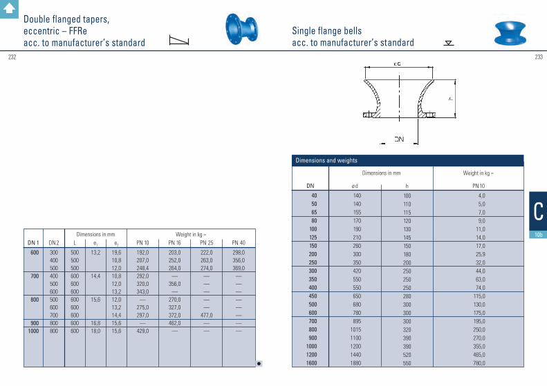
232 233
Single flange bellsacc. to manufacturer’s standard
Double flanged tapers, eccentric – FFReacc. to manufacturer’s standard
Weight in kg ≈Dimensions in mm
DN 1
600
700
800
9001000
DN 2
300400500400500600500600700800800
L
500500500600600600600600600600600
e1
13,2
14,4
15,6
16,818,0
e2
19,610,812,010,812,013,212,013,214,415,615,6
PN 10
192,0207,0248,4292,0320,0343,0
—275,0297,0
—429,0
PN 16
203,0252,0264,0
—356,0
—270,0327,0372,0462,0
—
PN 25
222,0263,0274,0
—————
477,0——
PN 40
298,0356,0369,0
————————
l
DN
40506580
100125150200250300350400450500600700800900
100012001600
ø d
140140155170190210260300350420550550650680780895
10151100120014401880
h
100110115120130145150180200250250250280300300300320390390520550
PN 10
4,05,07,09,0
11,014,017,025,932,044,063,074,0
115,0130,0175,0195,0250,0270,0355,0465,0780,0
Dimensions in mm Weight in kg ≈
Dimensions and weights
C10b

234 235
Blank flanges – X
* acc. to manufacturer’s standard
DN 400 PN 16DN 450 PN 16 and PN 40DN 500 PN 16 and PN 40
bb
Flange connection dimension acc. to EN 1092–2
DN
25* 32* 40* 50* 65*
80 100 125 150 200 250 275 300 350 400 450 500 600 700 800 9001000120014001600
PN 10
16,016,022,022,022,016,016,016,016,017,019,020,520,520,520,521,522,525,027,530,032,535,040,041,044,0
PN 16
16,016,022,022,022,016,016,016,016,017,019,0—
20,522,524,026,027,531,034,538,041,545,052,055,060,0
PN 25
16,016,022,022,0—
16,016,016,017,019,021,5—
23,526,028,030,532,537,0———————
PN 40
16,016,022,022,0—
16,016,020,523,027,031,5—
35,5——
45,048,0————————
PN 10
1,0 1,8 2,1 2,5 3,1 4,0 4,6 6,0 7,6 11,4 17,2 25,0 25,0 30,5 38,0 67,0 56,0 86,0 127,0 176,0 230,0 334,0582,0
—896,0
PN 16
1,0 1,8 2,1 2,5 3,1 4,0 4,6 6,0 7,6 11,4 16,8
— 24,5 34,5 46,0 91,5 79,0123,0174,0244,0323,0480,0737,0895,0
1221,0
PN 25
1,0 1,8 2,1 2,5 3,1 5,0 5,1 6,6 8,6 13,6 21,0
— 31,0 43,5 59,5 98,0106,0147,0
———————
PN 40
1,0 1,8 2,1 2,5 3,1 5,0 5,1 8,2 11,4 20,0 33,0
— 51,0
——
107,0165,0
————————
Weight in kg ≈ Dimensions in mmb
Dimensions and weights
C10b

236 237
Maße und Gewichte
Blank flanges with threaded bore – XGacc. to manufacturer’s standard
DN
40
50
65
80
100
125
150
175
200
250
300 350 400 450 500 600 700 800 90010001200
PN
10–40
10–40
10–40
10–40
10–40
10–40
10–40
10–40
10–40
10–40
10–40
RP (DIN EN 10226-1)
3/8 – 1 1/22
3/8 – 1 1/22 – 2 1/23/8 – 1 1/22 – 2 1/23/8 – 1 1/2
2 – 3 3/8 – 1 1/2
2 – 4 3/8 – 1 1/2
2 – 43/8 – 1 1/2
2 – 4 3/8 – 1 1/2
2 – 4 3/8 – 1 1/2
2 – 43/8 – 1 1/2
2 – 4
3/8 – 3
PN 10
16,036,016,036,016,036,017,036,019,036,020,520,520,520,522,525,027,530,032,535,040,0
PN 16
16,036,016,036,016,036,017,036,019,036,020,522,522,5—
27,531,034,538,041,545,052,0
PN 25
16,036,017,036,0——
19,036,021,536,023,526,026,0—
32,537,0—————
PN 40
20,536,023,036,0——
27,036,031,536,035,5——————————
Dimensions in mme
Dimensions and weights
22,027,022,027,022,027,016,030,016,036,0
C10b
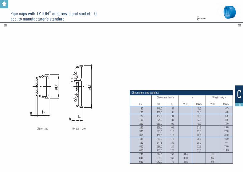
239238
DN 80 – 250 DN 300 – 1200
Pipe caps with TYTON® or screw-gland socket – Oacc. to manufacturer’s standard
DN
80 100 125 150 200 250 300 350 400 450 500 600 700 800 900
ø D
146,0 166,0 197,0 224,0 280,0 336,0 391,0 450,0 503,0 541,5 598,0 707,0 824,0 935,01042,0
t 1 84 88 91 94100105110110110120120120150160175
PN 16
34,438,041,5
PN 25
16,016,016,017,019,021,523,526,028,030,032,537,0
PN 16
160220345
PN 25
4,5 4,8 6,0 8,0 12,0 19,0 27,0 34,0 45,0
— 73,0110,0
Weight in kg ≈Dimensions in mm
Dimensions and weights
e C10b

240 241
Flanged socket duckfoot bends 90° – ENacc. to DIN 28 650
Conversion flanges DN 80 4 / 8 holesacc. to manufacturer’s standard
DN
80
PN
10 / 40
ø D
200
e
27
3,9
Dimensions in mm Weight in kg ≈
Dimensions and weights
1) without screw ring
DN
80100150
L1
165180220
L2
145158265
c
110125160
d
180200250
e
7,07,27,8
Weight in kg ≈ 1) Dimensions in mmwith
screw-gland socket PN 10 / PN 16
14,618,4
with TYTON® socket
PN 10 / PN 16
15,719,036,5
Dimensions and weights
C10b

243242
Plugs for screw-gland and TYTON® sockets – Pacc. to manufacturer’s standard
Double socket duckfoot bends 90° with Novo sockets – MMN / MMNRacc. to manufacturer’s standard
DN
80100150200
L1
119128157181
L2
100125150225
c
110125160190
d
180200250300
PN 10
13,617,819,230,5
Dimensions in mm Weight in kg ≈ e
7,07,27,88,4
Dimensions and weights
Also with 1, 2 or 3 draining bores with thread measured in inches available.Also with PE connection.
DN
40 80100125150200250300350400500
L
82 90 98103103108120125125125173
e1
20 22 23 23 23 23 23 25 25 25 25
e2
8,0 9,0 9,5 9,510,011,012,013,014,014,519,8
for screw-gland socket
PN 10 / PN 16
1,0 3,0 4,0 —
7,512,018,025,537,546,580,0
for TYTON® socket
PN 10 / PN 16
— 3,0 4,0 6,0 7,512,018,025,537,546,580,0
Dimensions in mm Weight in kg ≈
Dimensions and weights
C10b

245244
Screw plugs for screw-gland sockets – PXacc. to manufacturer’s standard
Screw rings for plugsacc. to manufacturer’s standard
Screw rings are needed in conjunction with plugs (plugs for screw-gland sockets) to close the pipeline.
DN
40
L
97
ø d
56
Rp
(EN 10226-1)3/4 – 2
PN 10 / PN 16
2,0
Dimensions in mm Weight in kg ≈
Dimensions and weights
DN
40 80100125150200
e
111214141720
L
657275788186
PN 10 / PN 16
1,62,93,44,45,59,0
Dimensions in mm Weight in kg ≈
Dimensions and weights
C10b

247246
C10c
Ductile cast iron special fittings
Further to the special fittings shown on the following pages, the following items are also available on request:
• Single socket pieces with angled branch 45° – C with screw-gland socket – acc. to manufacturer’s standard
For further information please give us a call or contact your specialist dealer. We look forward to your questions.
Contact: Export Department, Phone: +49 6093 87 560, e-mail: [email protected]

#249248
Double-flanged ball fittingwith upper flange DN 80 with special flange drilling as per WN 65
DN
80100125150 200250300400
L
200175225200250325375450
L 2
200175225200250325375450
Weight
in kg ≈
23,021,039,032,051,0118,0175,0290,0
Dimensions and weightsDimensions in mm
Flanged tee ball fittingwith upper flange DN 80 with special flange drilling as per WN 65
DN 1
80100
125
150
200
250
300
400
L
200175175225225200200200200250250250250250325325325325325325375375375375275450
L 1
200175175225225200200200200250250250250250325325325325325325375375375375275450
DN 2
80 80100100125 80 100125150 80 100125150200 80 100125150200250100125150200300400
L 2
200175175225225200200200200250250250250250325325325325325325375375375375275450
Weight
in kg ≈
25,024,025,036,045,033,034,035,037,050,052,053,054,056,096,098,099,0100,0103,0105,0148,0149,0150,0154,0157,0165,0
Dimensions and weightsDimensions in mm
also available with standard DN 80 upper flange also available with standard DN 80 upper flange
C10c

#251250
Connection drum
DN
6565
Lu
160160
interior thread Rp
1 1/4
„
1 1/2
„
L
210210
Weight
in kg ≈
4,13,8
Dimensions and weightsDimensions in mm
All flanged cross tee ball fittingwith upper flange DN 80 with special flange drilling as per WN 65
DN 1
80100
125
150
200
250
300
400
L
200175175225225225200200200200250250250250325325325325325375375375375450
L 1
200175175225225225200200200200250250250250325325325325325375375375375450
DN 2
80 80100 80100125 80 100125150 80 100150200100125150200250100150200300400
L 2
200175175225225225200200200200250250250250325325325325325375375375375450
Weight
in kg ≈
28,027,028,539,055,057,036,038,040,042,555,056,061,066,0102,0104,0111,0113,0117,0152,0155,0159,0168,0280,0
Dimensions and weightsDimensions in mm
also available with standard DN 80 upper flange
C10c

#253252
DN
40506580
100125150200250300350400450500600700800900
1000120014001600
d1
56668298
118144170222274326378429480532635738842945
1048125514621668
D
150165185200220250285340400455505565615670780895
101511151230145516751915
b
16161616161616171920202021222527303235404144
Dimensions
The dimension L is subject to customer specification and is to be measured from the flange sealing seat or from the bottom of the socket up to the centre of the puddle flange.
Fittingswith Puddle Flanges
Dimensions in mm
Flanged fittings:
Socket fittings:
* t = Socket length
C10c

255254
C11
These fittings for plastic pipelines are made of ductile cast iron and they are manufactured acc. to EN 12 842.The flanges of the KS fittings are acc. to EN 1092-2. All KS fittings are delivered with gaskets.
Coatings: see page 171.
Remarks forductile cast iron fittings for plastic pipelines
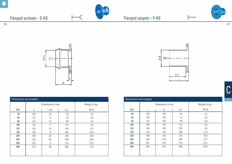
257256
C11
Flanged spigots – F-KSFlanged sockets – E-KS
DN
50 65 80100125150200250300400
A
100 110 120 125 155 150 180 220 235 310
L min
2014131118 82936 636
ø d1
63 75 90110140160 225 280 315450
PN 10
3,0 3,8 5,5 6,0 9,010,018,028,037,572,5
Dimensions in mm Weight in kg ≈
DN
50 65 80100125150200250300400
L
128130135150165170190248264294
EL
100105105120130140162219232261
ø d
63 75 90110140160 225 280 315 450
PN 10
3,2 4,5 5,0 6,5 9,611,016,027,737,255,8
Dimensions in mm Weight in kg ≈
Dimensions and weights Dimensions and weights

259258
C11
➜
Double socket tees with flanged branch – MMA-KS
Flanged socket duckfoot bends 90 ° – EN-KSacc. to manufacturer’s standard
DN
80 100150
L1
165180220
L2
140150145
c
110125160
ø d1
90110160
PN 10
15,620,536,2
Dimensions in mm Weight in kg ≈ d
180200250
DN 1
50 65
80
100
125
DN 2
50 50 65 50 65 80 50 65 80
100* 50* 65*
80100125
A
250265280285300315310325340360335350365385410
L
63 66 81 69 84 99 74 89104124 80 95110130135
ø d1
63 75 75 90 90 90110110110110140140140140140
h
140150150160160165170175175180185185190195200
PN 10
6,8 7,8 9,4 9,210,411,410,911,915,015,815,917,218,519,5 23,1
Weight in kg ≈ Dimensions in mm
Dimensions and weights
Dimensions and weights
* acc. to manufacturer’s standard

261260
C11
l
All socket tees – MMB-KSDouble socket tees with flanged branch – MMA-KS
DN 1
150
200
250
300
400
DN 2
50 65 80100125150
80* 100*
125150
200* 80100150200250 80100150
200* 250* 300* 80*100
200* 400*
A
360375390410435460455475500525575515535585635673550570620670720770660680780980
L
98 98116136161186128148173198248140160210260310152172222272322372200220320520
ø d1
160 160 160 160 160 160225225225225225280280280280280315315315315315315450450450450
h
205210205210215220235240245250260265270280290300295300310320330340355360380420
PN 10
19,2 21,0 20,8 24,2 26,5 29,7 34,9 37,6 39,8 44,7 51,4 48,0 52,0 57,6 65,6 73,6 58,9 61,6 71,1 79,4 89,2 93,0124,7130,5168,1219,0
Weight in kg ≈ Dimensions in mm
* acc. to manufacturer’s standard * ac
c. to
man
ufac
ture
r’s st
anda
rd
DN 1
5065
80
100
125
150
200
DN 2
50 50 65 50 65 80 50 65
80*100 80
100*125 80100
125*150 80100125150200
A
257272283292303216317328341360366385412391410437455456475502520578
L
70 73 84 76 87101 81 92106124112130157118136163181130148175 193 252
ø d1
63 75 75 90 90 90110110110110140140140160160160160225225225225225
l1
35 35 45 50 50 55 60 60 60 65 75 80 80 82 85 90 95115115120120130
PN 10
4,1 5,0 5,4 6,5 7,0 7,3 8,7 9,110,512,512,814,316,015,318,520,422,728,730,732,439,842,7
Weight in kg ≈ Dimensions in mm
h
129 134 142 141 148 158 150 158 168 180 182 194 206 190 203 215 228 219 232 244 257 289
ø d2
63 63 75 63 75 90 63 75 90110 90110140 90110140160 90110140160225
Dimensions and weights

263262
C11
➜
Double sockets with internal thread branch – MMI-KSDouble socket tapers – MMR-KS
DN
50
65
80
100
Rp
11 1/41 1/221
1 1/41 1/221
1 1/41 1/221
1 1/41 1/22
A
255255255255270270270270290290290290315315315315
L
68
71
74
79
ø d1
636363637575757590909090110110110110
PN 10
3,64,34,34,55,05,65,65,86,67,27,27,48,49,09,09,2
Dimensions in mm Weight in kg ≈ h
60
65
85
90
Dimensions and weights
DN 1
65 80
100
125
150
200
250
DN 2
50 50 65 65 80 80 100 100 125 125 150 150 200
A
213230232254257283286308307368372427430
L
20 28 24 36 31 48 41 53 42 77 71 102 79
ø d1
75 90 90 110 110 140 140 160 160 225 225 280 280
ø d2
63 63 75 75 90 90110110140140160160 225
PN 10
3,6 4,8 5,5 6,8 7,2 8,3 9,2 11,012,120,221,828,832,6
Weight in kg ≈ Dimensions in mm
Dimensions and weights

265264
C11
l
Double sockets with internal threaded branch – MMI-KS
DN
125
150
200
250300
Rp
11 1/41 1/221
1 1/41 1/221
1 1/41 1/2222
A
340340340340365365365365430430430430490523
L
85
91
103
115127
ø d1
140140140140160160160160225225225225280315
PN 10
10,912,512,512,715,115,715,715,927,027,627,627,841,451,2
Dimensions in mm Weight in kg ≈ h
105
115
155
180195

#267266
C12
Fittings as per EN 598.
Coating: inside and outside powder epoxy coating red/brown-red colour.Blue colour on request.
Further information see page 171 and 174.
Remarks forDuctile Iron Fittingsfor Sewage Pipelines

#269268
d3
DN 2
DN 1
d3
DN 2
DN 1 C12
Drilling saddle piece 90° 90° branch with clay pipe socket and NBR sealing
SM 90
Drilling saddle piece 45° 45° branch with clay pipe socket and NBR sealing
SM 45
for cast iron, steel or fibre cement pipes as per EN 598
for cast iron, steel or fibre cement pipes as per EN 598
DN 1
250 – 300350
400 – 600700 – 1200
DN 2
150
suitable for clay pipe spigot end
186
Weight in kg ≈
10,39,89,38,5
Dimensions and weights
ø d3 drilling
172
Dimensions in mm
DN 1
250 – 300350 – 400
DN 2
150
suitable for clay pipe spigot end
186
Weight in kg ≈
11,0
Dimensions and weights
ø d3 drilling
172
Dimensions in mm

#271270
d3
d2
DN 2
DN 1
d3
d2
DN 2
DN 1 C12
Drilling saddle piece 90° 90° branch with spigot for ductile iron pipe
SI 90
Drilling saddle piece 90° 45° branch with spigot for ductile iron pipe
SI 45
DN 1
250 – 300300350400
400 – 600500 – 600700 – 800
700 – 1200900 – 1200
DN 2
150200200200150200200150200
ø d2 Weight in kg ≈
9,115,316,014,17,213,212,66,613,0
Dimensions and weights
ø d3
ductile iron
170222222222170222222170222
clay pipe
186242242242186242242186242
drilling
172232232232172232232172232
Dimensions in mm
DN 1
250 – 300
DN 2
150
ø d2 ductile iron
170
Weight in kg ≈
9,1
Dimensions and weights
ø d3 drilling
172
Dimensions in mm
for cast iron, steel or fibre cement pipes as per EN 598
for cast iron, steel or fibre cement pipes as per EN 598

#273272
C12
TYTON®-couplings with TYTON® NBR sealsMM
Spigot end branch 67° ICI 67
as per EN 598 suitable for ductile iron sewage pipes
as per EN 598
DN 1
150200250300350400500600700800
DN 1
200
DN 2
150
ø d1
222
ø d2
170
L 1
568
L 2
326
h
310
Weight in kg ≈
26,0
ø d1
170222274326378429532635738842
Weight in kg ≈
8,011,514,721,029,036,058,079,0125,0126,0
Dimensions and weights
Dimensions and weights
ø D
210262315370425480590695810920
L
160165180200215210225250305325
Deviation per socket
5°
4°
3°
Dimensions in mm
Dimensions in mm

#275274
C12
as per EN 598 with NBR sealing
as per EN 598
DN 1
200
DN 2
150 STZ
ø d2
186
L 1
370
L 2
310
h
400
Deviation per socket
5°
Weight in kg ≈
38,0
Dimensions and weights
Dimensions in mm
Double socket branch with TYTON® sockets 45° branch with spigot for clay pipe MMI 45 or
67° branch with spigot for ductile iron pipe MMI 67
Double socket branch with TYTON® sockets 45° branch with clay pipe socket
MMM
DN 1
200200
DN 2
150 STZ150 GGG
ø d2
186170
L 1
370360
L 2
310222
h
400310
45°67°
Deviation per socket
5°5°
Weight in kg ≈
34,531,0
Dimensions and weights
Dimensions in mm
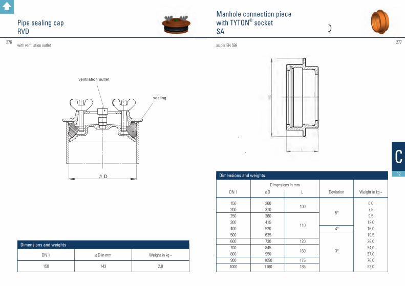
#277276
D
Dichtung
Entlüftungsventil
C12
Pipe sealing capRVD
DN 1
150
ø D in mm
143
Weight in kg ≈
2,0
Dimensions and weights
Manhole connection piece with TYTON® socketSA
as per EN 598
DN 1
1502002503004005006007008009001000
Weight in kg ≈
6,07,59,512,016,019,528,054,057,076,082,0
Dimensions and weights
ø D
260310360415520635730845950
10501160
L
100
110
120
160
175185
Deviation
5°
4°
3°
Dimensions in mm
with ventilation outlet
ventilation outlet
sealing

#279278
C12
DN
80100125150200250300350400500
L
500500550550650700750800900900
a x b
250 / 80250 / 100300 / 125290 / 150330 / 200360 / 250400 / 300500 / 350480 / 400550 / 500
PN 10
33 41 56 59
90124163232268414
Dimensions in mm Weight in kg ≈
Dimensions and weights
Double flanged hatchboxesacc. to manufacturer’s standard
Double socket hatchboxesacc. to manufacturer’s standard
DN
100150200250300350400500
L
450550600650700750850850
a x b
250 / 100290 / 150330 / 200360 / 250400 / 300500 / 350480 / 400550 / 500
PN 10
40 68 88120159227265385
Dimensions in mm Weight in kg ≈
Dimensions and weights
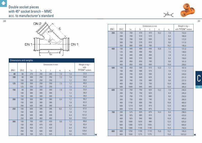
#281280
C12
➜
Double socket pieces with 45° socket branch – MMCacc. to manufacturer’s standard
DN 1
80100
125
150
200
250
300
DN 2
80 80100100125 80100150100150200100150200250100150200250300
Lu
270300300350350380380380500500500600500500600700450450700700
lu
200250250250250300300300360380380395400400460430470470500525
z
200250250250250300300300360380380395395430460430430420500525
e1
7,0 7,2
7,5
7,8
8,4
9,0
9,6
Dimensions in mm
e2
7,0 7,0 7,2 7,2 7,5 7,0 7,2 7,8 7,2 7,8 8,4 7,2 7,8 8,4 9,0 7,2 7,8 8,4 9,0 9,6
with TYTON® sockets
22,0 25,0 30,0 40,0 41,0 33,0 36,0 39,0 56,2 62,0 65,0 67,0 71,0101,0120,0 89,6 93,4 95,0128,0142,6
Weight in kg ≈
Dimensions and weights
l
DN 1
350
400
500
600
700
800
DN 2
150200250300350100125150200300400100150200250300400500150200250300400500600200300400500600700600800
Lu
700 700 700 700 880 440 440 440 640 850 850 450 450 740 740 740 850 1040 750 750 750 750 1150 1210 1210 575 925 92510801380138012501550
lu
470 510 530 570 690 480 490 490 570 650 650 590 590 620 640 720 720 845 750 750 775 800 800 920 985 825 885 94010201070114011501275
z
470 510 530 610 760 440 450 450 580 700 650 515 515 550 620 680 750 845 620 620 680 740 765 915 975 675 810 890 9901055114011101275
e1
10,2
10,8
12,0
13,2
14,4
15,6
Dimensions in mm
e2
7,8 8,4 9,0 9,6 10,2 7,2 7,5 7,8 8,4 9,6 10,8 7,2 7,8 8,4 9,0 9,6 10,8 12,0 7,8 8,4 9,0 9,6 10,8 12,0 13,2 8,4 9,6 10,8 12,0 13,2 14,4 13,2 15,6
with TYTON® sockets
153,0 160,0 172,0 177,0 195,0 131,0 138,0 141,0 159,0 181,0 209,0 167,0 177,0 220,0 231,0 237,0 266,0 385,0 240,0 245,0 250,0 260,0 400,0 482,0 506,0 298,0 433,0 445,0 635,0 693,0 750,0 745,01013,0
Weight in kg ≈

283282 283
DD
Laying and assembly instructions
Back to summary

285284
Note
The DVGW standard GW 368 „Thrust-resistant socket joints for pipes, fittings and valves made of ductile cast iron or steel“ is presently being modified.
For up-to-date information please refer to the FGR/EADIPS website at
www.eadips.org
Da

287286
TYTON® ring NOVO-SIT® ring
5.1
Da
General instructionsFor laying pressure pipes, fittings and valves with thrust resisting joint NOVO-SIT®, the “laying instructions for ductile cast iron pressure pipes and fittings with TYTON® joint” should be observed.
Application fieldNOVO-SIT® locking rings are available for the nominal diameters DN 80 up to 800.For the allowable operating pressures, please refer to page 32.This self-anchoring, thrust resisting socket joint substitutes concrete anchoring blocks.
The suitable number of thrust resisting connections has been laid down in DVGW standard GW 368 and has to be observed.Before installation in lines for bridges, ducts or river-crossings, please contact our service team.
Figure: NOVO-SIT® ring with vulcanised segments made of chromium steel. Assembling steps
Laying instructions for ductile cast iron pressure pipes, fittings and valves, equipped with thrust resisting joint NOVO-SIT®

288 289
5.1
Da
Segment marking dots
Plates
The exact position of the TYTON® ring has to be tested with a suitable gauge between the segments on the whole circumference.
Note: Deviation of the installed thrust resisting joint is possible as follows: up to DN 400 – 3° up to DN 700 – 2° up to DN 800 – 1°
A pipe with 6 m length and 1° deflection deviates approx. 10 cm off the neutral pipe axis.
Dismantling of thrust resisting joints
Push the spigot completely into the socket.Lubricate the dismantling blades on both sides and drive them into the socket gap at the segment marking dots, with the help of the hammering device.Use the pipe laying tool or dismantling collar to draw the spigot out of the socket.
Laying instructions for ductile cast iron pressure pipes, fittings and valves, equipped with thrust resisting joint NOVO-SIT®
1. Clean the inside of the socket, particularly the TYTON® groove.2. Insert gasket (TYTON® ring) by deflecting and squeezing, so that the gasket is firmly bedded
in its seating. The inner part of the inserted TYTON® ring should be slightly lubricated.3. Insert NOVO-SIT® ring into the pre-chamber.4. Clean the spigot end and slightly lubricate it, particularly at the rounded end; then insert through
the NOVO-SIT® ring until it touches the the TYTON® ring concentrically. From DN 300 up, this already requires a laying tool.5. Further assembly can be made, depending on the nominal dimension, with a lever or a laying tool.
Deviation should be avoided.
Important:Changes of circumferential directions have to be arranged before connecting ( e.g. installation of outlets, tees a. s. o. ).
Laying device V 300 D
Attention:After connecting both parts, the locking of the segments has to be accomplished by moving the levers in the opposite direction.
Alternate moving of the levers draws the spigot end into the socket Locking
Gauge

General instructions
Laying instructions for ductile cast iron pressure pipes, fittings and valves, equipped with thrust resisting joint TYTON® SIT®
For laying pressure pipes, fittings and valves with thrust resisting joint TYTON® SIT® the “laying instructions for ductile cast iron pressure pipes and fittings with TYTON® joint” should be observed.
Figure: After cleaning, the TYTON® SIT®
thrust resisting ring (with segments) has to be deformed acc. to the illustration an inserted into the socket.
Application field: TYTON® SIT® locking rings are available for the nominal diameters DN 80 up to DN 400.For the allowable operating pressures and pressure classes please refer to page 30. This self-anchoring, thrust resisting socket joint substitutes concrete anchoring blocks. The suitable number of thrust resisting connections has been laid down in DVGW-standard GW 368 and has to be observed.
Before installation in lines for bridges, ducts or river crossings, please contact our service team.
Assembling steps 1. Clean the inside of the socket, particularly the TYTON® groove.2. The TYTON® SIT® ring has to be cleaned, deformed acc. to the illustration and inserted into
the socket. Ensure that the S-bend is located between two segments during deformation. The inner part of the inserted TYTON® SIT® ring should be slightly lubricated.
3. Clean the spigot end, slightly lubricate and insert concentrically into the socket until it touches the TYTON® SIT® ring.
4. Mount the laying tool as per the illustration and draw the spigot end into the socket (see page 286).
Deviation should be avoided!
291290
5.1
Da

293292
5.1
Da
Alternate moving of the levers draws the spigot end into the socket Locking
Laying instructions for ductile cast iron pressure pipes, fittings and valves, equipped with thrust resisting joint TYTON® SIT®
Important: Changes of circumferential directions have to be arranged before connecting ( e.g. installation of outlets, tees a. s. o.).
Laying device V 300 D
Attention: After connecting both parts, the locking of the segments has to be accomplished by moving the levers in the opposite direction.
The exact position of the TYTON® SIT® ring has to be tested with a suitable gauge between segments on the whole circumference.
Dismantling plate
Note:Deviation of the installed thrust resisting joint is possible up to 3°.A pipe with 6 m length and 1° deflection deviates approx. 10 cm off the neutral pipe axis. Dismantling of thrust resisting joints
Push the spigot completely into the socket with the laying tool so the segments are no longer under pressure.Lubricate the dismantling blades on both sides and drive them into the socket gap around the complete circumference, with the help of the hammering device.Use the pipe laying tool or dismantling collar to draw the spigot out of the socket.If it should not be possible to insert the blades around the whole circumference, the pipeline has to be cut. Marking of the installed thrust resisting joint
For a durable marking, we supply a profiled rubber ring with a blue-coloured strip. This marking ring should be applied as shown in the illustration.
Gauge

295
Laying instructions for ductile cast iron pressure pipes, fittings and valves, equipped with thrust resisting joint TYTON SIT PLUS® (TSP®)
294
5.1
Da
General instructions
For laying pressure pipes, fittings and valves with thrust resisting joint TYTON SIT PLUS® ( TSP® ), the “laying instructions for ductile cast iron pressure pipes and fittings with TYTON® joint” as well as special installation instructions of the pressure pipe manufacturer should be observed.The TYTON SIT PLUS® sealing and locking ring is available for dimensions DN 80 up to DN 600.
Three basic attributes of the TYTON SIT PLUS® ring are:
Joint construction
marking: “TYTON SIT PLUS®“
notch within the sealing bulge
4 teeth in each segment
TSP® ring with stainless steel segments
TYTON® socket Cast iron pipe
Marking ring

297
Laying instructions for ductile cast iron pressure pipes, fittings and valves, equipped with thrust resisting joint TYTON SIT PLUS®
296
For allowable operating pressures and pressure classes please refer to page 29.
This self-anchoring, thrust resisting socket joint substitutes concrete anchoring blocks. The suitable number of thrust resisting connections has been laid down in DVGW standard GW 368 and has to be observed.Before installation in lines for bridges, ducts or river-crossings, please contact our service team. Assembling steps1. Clean the inside of the socket, particularly the
TYTON® groove.2. The TYTON SIT PLUS® ring has to be
cleaned, deformed acc. to the illustration and inserted into the socket. Ensure that the S-bend is located between two segments dur-ing deformation. The inner part of the inserted TYTON SIT PLUS® ring should be slightly lubricated.
3. Push the marking ring, labeled with a white stripe, onto the cast iron pipe.
4. Clean the spigot end, slightly lubricate and insert concentrically into the socket until it touches the TSP® ring.
5. Mount the laying tool as per the illustration and draw the spigot end into the socket.
Deviation should be avoided!
Important:Changes of circumferential directions have to be arranged before connecting (e.g. installation of outlets, tees a. s. o.).
5.1
Da
Alternate moving of the levers draws the spigot end into the socket Locking
Laying device V 300 D
Attention: After connecting both parts, the locking of the segments has to be accomplished by moving the levers in the opposite direction.
The exact position of the TYTON SIT PLUS® ring has to be checked with a suitable gauge between segments on the whole circumference.
Note:Deviation of the installed thrust resisting joint is possible up to 3°.A pipe with 6 m length and 1° deflection deviates approx. 10 cm off the neutral pipe axis.
gauge
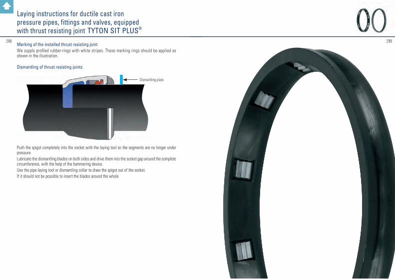
299298Marking of the installed thrust resisting jointWe supply profiled rubber-rings with white stripes. These marking rings should be applied as shown in the illustration. Dismantling of thrust resisting joints
Push the spigot completely into the socket with the laying tool so the segments are no longer under pressure.Lubricate the dismantling blades on both sides and drive them into the socket gap around the complete circumference, with the help of the hammering device.Use the pipe laying tool or dismantling collar to draw the spigot out of the socket.If it should not be possible to insert the blades around the whole
Dismantling plate
Laying instructions for ductile cast iron pressure pipes, fittings and valves, equipped with thrust resisting joint TYTON SIT PLUS®

Laying instructions for ductile cast iron pressure pipes and fittings, equipped with thrust resisting joint Düker SMU
301300
5.1
Da
General instructions:For laying pressure pipes and fittings with thrust resisting joint Düker SMU, the “laying instruc-tions for ductile cast iron pressure pipes and fittings with screw-gland joint” should be observed. The screw-gland joint Düker SMU only works as thrust resisting joint and gasket, if there is enough space between socket and spigot. The spigot should be drawn into the socket by tightening the screw ring. Only by this way a secure pressing of the gasket is garanteed.
Application field:The thrust resisting joint Düker SMU is available for dimensions DN 40 up to DN 65 and for nominal pressures up to 16 bar (pressure class C50).This self-anchoring, thrust resisting socket joint substitutes concrete anchoring blocks. The suitable number of thrust resisting connections has been laid down in DVGW-standard GW 368 and has to be observed.Before installation in lines for bridges, ducts or river-crossings, please contact our service team. Joint construction
Clean the inside of the socket and the spigot and on a length of at least 300 mm. Drive in the clearance markings L 1 and L 2 with the center punch.
Center punch Block strapping
min. 300 mm
L1
L2

303302
5.1
Da
Press the gasket evenly into the socket (centering) with the help of the inserting device. Push in the gliding ring and locking ring until the gliding ring touches the gasket.Tighten the screw ring with a hammer or a ram until it cannot be turned any more.
Check the correct installation depth: Block strapping must be within L2 ± 3 mm.After installation of the connection in centrical position, pipes can be deviated
DN 80 – 200 up to 3 ° and DN 250 – 400 up to 2 °
Laying instructions for ductile cast iron pressure pipes and fittings, equipped with thrust resisting joint Düker SMU
Insert the screw ring, locking ring, gliding ring and gasket in this sequence behind the centre punch marking L2. Lubricate the pipe end, face of gasket, gliding ring and locking ring as well as the face and the screw thread of the screw ring with the lubricant supplied by the pipe manufacturer.Insert the pipe end into the socket, centre it and check the installation depth L1.Do not remove lifting gear yet.
Block strapping Gasket Gliding ring Locking ring Screw ring
L1 L2
Block strapping100 mm
DN
Standard socketLong socket
L1
170209
L2
178217
65 L1
164203
L2
172211
50 L1
161200
L2
169208
40
Dimensions L1 and L2 in mm
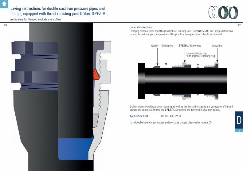
Laying instructions for ductile cast iron pressure pipes and fittings, equipped with thrust resisting joint Düker SPEZIAL, particulary for flanged sockets and collars
305304
5.1
Da
General instructions: For laying pressure pipes and fittings with thrust resisting joint Düker SPEZIAL, the “laying instructions for ductile cast iron pressure pipes and fittings with screw-gland joint” should be observed.
Enables mounting without block strapping as well as the thrusted-restisting end connection of flanged sockets and collars. Screw ring and SPEZIAL-Screw ring are delivered in blue-grey colour.
Application field: DN 80 – 400, PN 16
For allowable operating pressures and pressures classes please refer to page 35.
Gasket Gliding ring
Element rubber ring with segments / locking ring
SPEZIAL-Screw ring Screw ring
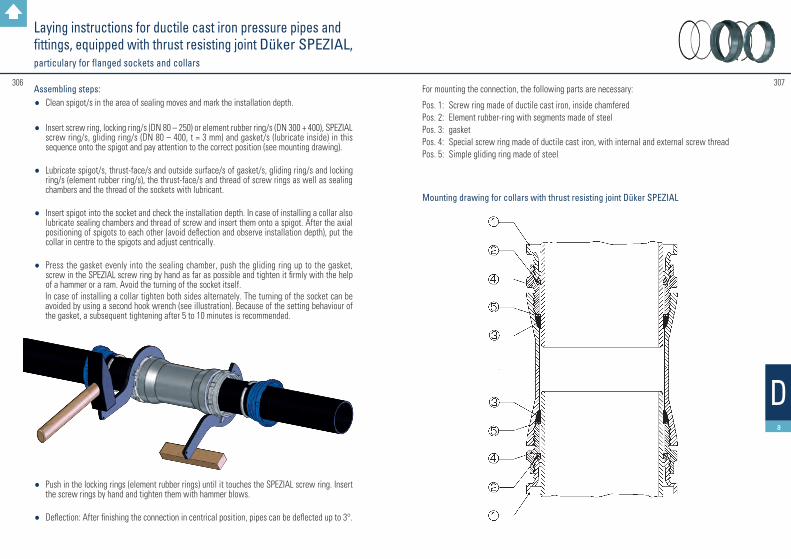
Laying instructions for ductile cast iron pressure pipes and fittings, equipped with thrust resisting joint Düker SPEZIAL, particulary for flanged sockets and collars
307306
5.1
Da
For mounting the connection, the following parts are necessary:
Pos. 1: Screw ring made of ductile cast iron, inside chamferedPos. 2: Element rubber-ring with segments made of steelPos. 3: gasketPos. 4: Special screw ring made of ductile cast iron, with internal and external screw threadPos. 5: Simple gliding ring made of steel
Assembling steps:• Clean spigot/s in the area of sealing moves and mark the installation depth.
• Insert screw ring, locking ring/s (DN 80 – 250) or element rubber ring/s (DN 300 + 400), SPEZIAL screw ring/s, gliding ring/s (DN 80 – 400, t = 3 mm) and gasket/s (lubricate inside) in this sequence onto the spigot and pay attention to the correct position (see mounting drawing).
• Lubricate spigot/s, thrust-face/s and outside surface/s of gasket/s, gliding ring/s and locking ring/s (element rubber ring/s), the thrust-face/s and thread of screw rings as well as sealing chambers and the thread of the sockets with lubricant.
• Insert spigot into the socket and check the installation depth. In case of installing a collar also lubricate sealing chambers and thread of screw and insert them onto a spigot. After the axial positioning of spigots to each other (avoid deflection and observe installation depth), put the collar in centre to the spigots and adjust centrically.
• Press the gasket evenly into the sealing chamber, push the gliding ring up to the gasket, screw in the SPEZIAL screw ring by hand as far as possible and tighten it firmly with the help of a hammer or a ram. Avoid the turning of the socket itself.
In case of installing a collar tighten both sides alternately. The turning of the socket can be avoided by using a second hook wrench (see illustration). Because of the setting behaviour of the gasket, a subsequent tightening after 5 to 10 minutes is recommended.
• Push in the locking rings (element rubber rings) until it touches the SPEZIAL screw ring. Insert the screw rings by hand and tighten them with hammer blows.
• Deflection: After finishing the connection in centrical position, pipes can be deflected up to 3°.
Mounting drawing for collars with thrust resisting joint Düker SPEZIAL

Laying instructions for ductile cast iron pressure pipes, fittings and valves, equipped with thrust resisting joint NOVO-Grip® III
309308
5.1
Da
Gasket NOVO-Grip® III-ring
PE-HD pipe
Application field:NOVO-Grip® III locking rings are available for dimensions DN 90 / 110 / 140 / 160 / 225 and for operating pressures PN 10/16. This self-anchoring, thrust resisting socket joint substitutes concrete anchoring blocks.The suitable number of thrust resisting connections has been laid down in DVGW-standard GW 368 and has to be observed.Before installation in lines for bridges, ducts or river-crossings, please contact our service team.
Assembling steps1. Clean the inside of the socket and the spigot end.2. Insert gasket into TYTON® chamber.3. Insert NOVO-Grip® III ring into pre-chamber.4. Spigot of pipe has to be rounded and smoothened.5. Insert stabilising bush completely.6. Drive the spreading wedge into the stabilising bush until stretching. Any protruding end of the
spreading wegde has to be cut off so it is flush with the bush.7. Insert pipe into the socket through NOVO-Grip® III ring until touching the gasket.8. Connect the joint by employing commercial pipe-laying tools.
Please avoid deviation while drawing the spigot into the socket!
Important: Changes of circumferential directions have to be arranged before connecting. ( e.g. installation of outlets, tees a. s. o. )
Note: Fittings and valves with a nominal dimension of DN 200 for pipeline diameters of 225 mm do not have a standard Novo socket! These parts are equipped with an adapted geometry and are marked with the sign „for PE-HD Pipes“. Please consider this when you order your pipeline components.
These instructions are also applicable for the thrust resisting joint NOVO-Grip® PVC combined with PVC pipes.

311310
Laying instructions for ductile cast iron pressure pipes, fittings and valves, equipped with thrust resisting joint NOVO-Grip® III
Gasket (GKS) NOVO-Grip® III ring PE-HD pipe
Dismantling of thrust resisting joints
1. Push in the spigot until it touches the ground of the socket.
2. Lubricate the dismantling plates and drive them in on the whole circumference with the help of the hammering device.
3. Dismantle by using the laying tool.
Attention: Take care of length differences because of variation in temperature when laying plastic pipes.
E.g. PE-HD pipe length 10 m, D t = 10 °; D l approx. 20 mm.
Gasket (GKS)NOVO-Grip® III ring
Dismantling plate

#313312
5.2
Db
Laying Instructions for Bolted-Gland Socket Joints
Laying Instructions for Bolted-Gland Socket Joints
Installation: • Clean the socket (particularly the sealing seat), the spigot to be inserted, the sealing and the
bolted-gland ring
• Mark the distance measure:
• Push the bolted-gland ring and sealing ring behind the marking
• Insert the spigot into the socket so a distance of 100 mm is kept between the mark and the flange
Do not use any lubricants!
• Push the sealing into the sealing seat
• Push the bolted-gland ring onto the sealing and align it using hardwood wedges
• Insert hammer head bolts into the bolted-gland flange und the bolted-gland ring
• Screw on the nuts by hand as tightly as possible
• Tighten the nuts with ring spanners one by one (always two nuts facing each other) by a half or one turn each time
DNL
DNL
100160
500172
125160
600180
150160
700182
200162
800190
250162
900197
300165
1000200
350165
1200*215
400170
1400*275
450172
1600*275
*DN 1200-1600: please observe page 315!
Length of measure L in mm

#315314
5.2
Db
Laying Instructions for Bolted-Gland Socket Joints
Laying Instructions for Bolted-Gland Socket Joints
The tightening is correct when the bolted-gland ring has pushed itself at least 6 mm into the sealing. The depth can be determined by measuring the height of the bolted-gland ring, and the depth from the edge of the bolted-gland ring up to the sealing ring before and after tightening the bolts. The depth on one bolted-gland socket joint should be as uniform as possible.
Control the correct depth once more.
Deflection: After tightening the joint in a centred and aligned position, the pipes can be put in an angle of up to 3°.An angle of 1° results in a deviation of a 6 m pipe from the axis of the connected pipe or fitting by approx. 10 cm; for 3° it is approx. 30 cm.
Fittings with bolted-gland socket joints in DN 1200 to 1600 are supplied with specific installation instructions which must be observed in detail.
The marking of the distance measure and the insertion of the bolted-gland ring and the sealing correspond to page 312.
Then assemble the bolts with the washers and insert them. Lubricate the bolt threads and screw on the nuts and washers by hand while aligning the sealing.
Then tighten the nuts one by one, always two nuts facing each other. The socket flange and the bolted-gland ring must remain parallel and never differ by more than 15 mm. The required torque is 150 ±20 Nm.
Before the pressure test, control the torque once more.
Deflection: After mounting the joint in a centred and aligned position, the pipes can be deflected by up to 2°.Attention: in this case tighten the bolts at first with a torque of only 60 ±10 Nm, and after deflection tighten with 150 ±20 Nm.
DN 1200 to 1600
Hexagonal head bolts and washers instead of hammer head bolts

317316
5.3
Dc
Assembly instructions for pressure pipes and fittings with flanges
Assembly instructions for pressure pipes and fittings with flanges
1. Clean the flange, raised face and gasket. Check all parts for proper conditions. Do not use damaged parts.
2. In case of installation with unprotected screws, especially in soils with corrosion risk, the screw connections must be protected (f. e. with bituminous tapes).
3. Pipes and fittings must be bedded carefully and the filling and compacting of the pipe ditch must be done carefully as well. Pipes and fittings should never be supported with stones or similar hard material and must be laid on stonefree base. Rocky base must be covered with min. 15 cm layer of sand, gravel or split.
4. For flanged pipes and fittings the general rule for the arrangements of the boltholes is that no bolthole is located in the flange axis, which is upright to the pipeline level.
5. Notes for the installation of flanged fittings (in particular double flanged tapers / FFR):
To avoid installation errors, special installation marks (notches) are cast on at the flanges in opposite positions. It is necessary to ensure that these marks are arranged for installation in vertical or horizontal direction.

319318
5.4
Dd
Assembly instructions for drilling saddle pieces
Required tools: • core drilling machine• core bit Ø 172 +1,5/-0 mm for DN 150• core bit Ø 232 +1,5/-0 mm for DN 200• drilling machine or cordless electric drill• hammer• punch• carbide drill Ø 13 mm (e.g. DIN 8037)• file• brush• lubricant (included in the delivery)• protective paint
Assembly:
Step 1: Drill into the sewage pipe with the core drilling machine and the corresponding core bit.
Example: Double flanged taper ( FFR ) 350 / 250, PN 10
right wrong
In case of wrong installation and due to the unequal number of boltholes on double-flanged tapers, the connecting valves or fittings will be slanting from the vertical axis. Possible deviations are up to 22.5°, depending on the diameter.
Attention:On large diameters, a deviation is hardly detectable!
Remarks:Please note that DVGW standard-workingsheet GW 368 should be observed.
Assembly instructions for pressure pipes and fittings with flanges

#321320
5.4
Dd
Step 2: Deburr, clean, dry and repaint the drilling edges with a fast-drying epoxy resin paint. On sewage pipes with external cement mortar coating, this coating is to be removed in the contact area of the spot-drilling saddle piece.
Step 3: Insert the saddle sealing into the drill hole. Fit on the saddle piece and mark the position of the screw holes on the pipe by punching through the screw holes of the saddle piece. Then remove the saddle piece and the sealing.
Assembly instructions for drilling saddle pieces
Assembly instructions for drilling saddle pieces
Step 4: Drill two holes on the punch marks with the 13 mm carbide drill. Then insert the screws and sealing sleeves contained in the delivery into the drill holes from the inside and drive them cautiously through with a hammer.
Step 5: Re-insert the saddle sealing into the drill hole. Watch out for exact positioning. Apply lubricant to the sealing and put on the saddle piece.
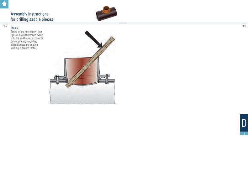
#323322
Assembly instructions for drilling saddle pieces
Step 6: Screw on the nuts lightly, then tighten alternatively and evenly until the saddle piece connects. Do not use any lever that might damage the coating (use e.g. a square timber).
Dd

For further information on our product programme please refer to our web site:
www.dueker.deFITTINGS AND VALVES
DRAINAGE TECHNOLOGY
JOBBING FOUNDRY
Back to summary

