independent orbiter assessment - nasa and water spray boiler c-35 mechanical actuation system c-35...
TRANSCRIPT
INDEPENDENT ORBITER ASSESSMENT
FMEA/CIL
ASSESSMENT
FINAL REPORT
16 SEPTEMBER 1988
https://ntrs.nasa.gov/search.jsp?R=19900001644 2018-06-30T12:37:18+00:00Z

MCDONNELL DOUGLAS ASTRONAUTICS COMPANY
ENGINEERING SERVICES
SPACE TRANSPORTATION SYSTEM ENGINEERING AND OPERATIONS SUPPORT
WORKING PAPER NO. 1.0-WP-VA88003-47
INDEPENDENT ORBITER ASSESSMENT
FMEA/CIL ASSESSMENT FINAL REPORT
16 SEPTEMBER 1988
This Working Paper is Submitted to NASA under
Task Order No. VA88003, Contract NAS 9-17650
Prepared by: /_LJ
I
W Hinsdale
Independent OrbiterAssessment
Prepared by: ____
Assessment
Prepared by:
Section Manager-FMEA/CIL
Independent Orbiter
Assessment
Approved by
Technical Manager
Independent Orbiter
Assessment
Approved by: G._L./o_r_ac___k
Project ManagerSTSEOS


CONTENTS
Section
1.0
2.0
3.0
4.0
5.0
6.0
Title
EXECUTIVE SUMMARY
INTRODUCTION
RESULTS
GENERAL CONCLUSIONS AND OBSERVATIONS
RECOMMENDATIONS
REFERENCES
Page
1
5
7
9
ii
12
APPENDIX A ACRONYMS
APPENDIX B DEFINITIONS, GROUND RULES,AND ASSUMPTIONS
B.I
B.2
A-I
B-I
Definitions B-2
Project Level Ground Rules and Assumptions B-4
APPENDIX C SUBSYSTEM ASSESSMENT SUMMARIES
C.I
C.2
C.3
C.4
C.5
C.6
C.7
C.8
C.9
C.10
C.ll
C.12
C-I
C.17
C.18
C.19
C.20
C.21
C.22
C.13
C.14
C.15
C.16
Fuel Cell Powerplant C-2
Hydraulic Actuators C-2
Displays and Controls C-8
Guidance, Navigation and Control C-IO
Orbiter Experiments C-10
Auxiliary Power Unit C-10
Backup Flight System C-14
Electrical Power, Distribution & Control C-17
Landing and Deceleration C-17
Purge, Vent and Drain C-20
Pyrotechnics C-23
Active Thermal Control System and
Life Support System C-25
Crew Equipment C-30Instrumentation C-30
Data Processing System C-30
Atmospheric Revitalization Pressure
Control System C-34
Hydraulics and Water Spray Boiler C-35
Mechanical Actuation System C-35
Manned Maneuvering Unit C-38
Nose Wheel Steering C-41
Remote Manipulator System C-43
Atmospheric Revitalization System C-44

APPENDIX C SUBSYSTEM ASSESSMENT SUMMARIES (Cont.)
C.23
C.24
C.25
C.26
C.27
C.28
Extravehicular Mobility Unit
Power Reactant Supply and
Distribution System
Main Propulsion System
Orbital Maneuvering System
Reaction Control System
Communication and Tracking
APPENDIX D COMPARISON OF IOA SUBSYSTEMS TO ROCKWELL
CIL PACKAGES
Page
C-47
C-50
C-52
C-55
C-60
C-65
D-I
ii
Table
Table i-i
Table 1-2
Table 2-1
LIST OF TABLES
Title
FMEA/CIL ASSESSMENT OVERVIEWCIL ISSUE RESOLUTION
ORBITER AND GFE SUBSYSTEMS
Page
3
4
6
iii

Independent Orbiter AssessmentFMEA/CIL Assessment Final Report
1.0 EXECUTIVE SUMMARY
The McDonnell Douglas Astronautics Company (MDAC) was selected in
June 1986 to perform an Independent Orbiter Assessment (IOA) of
the Failure Modes and Effects Analysis (FMEA) and Critical Items
List (CIL). Direction was given by the Orbiter and GFE Projects
Office to perform the hardware analysis and assessment using the
instructions and ground rules defined in NSTS 22206, Instructions
for Preparation of FMEA and CIL.
The IOA analysis featured a top-down approach to determine
hardware failure modes, criticality, and potential critical
items. To preserve independence, the analysis was accomplished
without reliance upon the results contained within the NASA and
Prime Contractor FMEA/CIL documentation. The assessment process
compared the independently derived failure modes and criticality
assignments to the proposed NASA post 51-L FMEA/CIL
documentation. When possible, assessment issues were discussed
and resolved with the NASA subsystem managers. Unresolved issues
were elevated to the Orbiter and GFE Projects Office manager,
Configuration Control Board (CCB), or Program Requirements
Control Board (PRCB) for further resolution. An issue generally
refers to a disagreement between the NASA FMEA/CIL and the IOA
failure mode analysis results. This process was reviewed twice
by the National Research Council, Shuttle Criticality Review and
Hazard Analysis Audit Committee, and was concluded to be
acceptable.
As subsystem FMEA/CIL assessments were completed during the
course of the task, separate subsystem assessment reports were
published. The remaining assessments were being completed as
revised FMEA/CIL documentation became available. The IOA task
was brought to a premature conclusion in March 1988 which
resulted in several subsystem assessments with open issues.
Subsequent authority was received that allowed for the resolution
of all the remaining open CIL issues and the identification of
those with safety implications. The resulting resolution
assessment worksheets are documented in a companion volume to
this report, entitled "IOA CIL Issues Resolution Report", dated
16 September 1988 (reference 71). Summaries of each subsystem
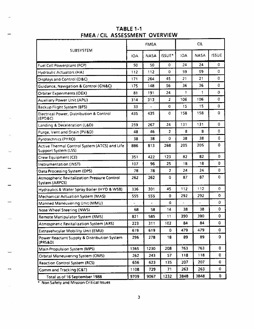
assessment are provided in Appendix C of this report. Table i-i
presents an overview of the FMEA/CIL assessments. Resolution ofall CIL issues is shown in Table 1-2. All CIL issues have been
resolved. Some FMEA issues remain open; however, these do not
involve safety or mission critical hardware.
Several Orbiter FMEA/CIL assessment difficulties encountered
during the task were attributed to interpretion of NSTS 22206
ground rules and instructions. For example, the Prime Contractor
occasionally used a very broad redundancy interpretation approach
which caused more IR and 2R functional criticalities. The

definition of redundancy was expanded to include redundancy atthe higher assembly and subsystem levels, in addition to like andunlike redundancy to the hardware component being failed. IOA,in its original analysis, limited redundancy to failure itemsunder study, which resulted in less severe functionalcriticalities. IOA accepted the Prime Contractor's more severe
criticalities when exact NSTS 22206 ground rules could not be
clearly deciphered.
The most important Orbiter assessment finding was the previously
unknown "stuck" autopilot push-button criticality i/i failure
mode. The worst case effect could cause loss of crew/vehicle
when the microwave landing system is not active. The Prime
Contractor has been directed by the CCB to add the failure mode
to the FMEA/CIL documentation and to implement a software change
to bypass a stuck "Auto" switch.
SPAR Aerospace conducted their Remote Manipulator System (RMS)
failure mode analysis in a manner similar to IOA and consistent
with NSTS 22206. One major assessment difficulty affecting 69
FMEA/CIL items concerned uncommanded motion of the arm while
within 2 feet of the Orbiter, payload, or a suited crewman. The
arm malfunction detection software design specification calls for
a stopping distance of 2 feet. Concern exists that the arm will
not be stopped within this 2 foot envelope for all failure modes.
However, IOA could not prove conclusively that the uncommanded
motion failure modes were a threat and should be assigned a worst
case effect criticality of i/I. Therefore, IOA withdrew the
issue and accepted the NASA 2/IR criticality assignments.
The Extravehicular Maneuvering Unit (EMU) FMEA/CIL documentation
prepared by Hamilton Standard followed NSTS 22206 ground rules
and was in general agreement with IOA. Assessment of the Manned
Maneuvering Unit (MMU) was not completed due to the NASA decision
to defer review of the MMU FMEA/CIL.
In conclusion, NASA and Prime Contractor Post 51-L FMEA/CIL
documentation assessed by IOA is believed to be technically
accurate and complete. All CIL issues have been resolved. No
FMEA issues remain that have safety implications. Consideration
should be given, however, to upgrading NSTS 22206 with definitive
ground rules which more clearly spell out the limits of
redundancy.
FMEA/CIL
SUBSYSTEM
TABLE 1-1
ASSESSMENT OVERVIEW
FMEA
IDA NASA ISSUE*
Fuel Ceil Powerplant (FCP) 50 50 0
Hydraulic Actuators (HA) 112 112 0
Displays and Control (D&C) 171 264 45
Guidance, Navigation & Control (GN&C) 175 148 56
Orbiter Experiments (OEX) 81 191 24
Auxiliary Power Unit (APU) 31_4 313 2
Backup Flight System (BFS) 33 0
Electrical Power, Distribution & Control 435 435 0EPD&C)
Landing & Deceleration (L&D) 259 267 24
Purge, Vent and Drain (PV&D) 48 46 2
Pyrotechnics (PYRO) 38 38 0
Active Thermal Control System (ATCS) and Life 886 813 268Support System (LSS)
Crew Equipment (CE) 351 422 123
Instrumentation (INST) 107 96 25
Data Processing System (DPS) 78 78 2
Atmospheric Revitalization Pressure Control 262 262 0
System (ARPCS)
Hydraulics & Water Spray Boiler (HYD & WSB) 336 301
Mechanical Actuation System (MAS) 555 555
Manned Maneuvering Unit (MMU)
Nose Wheel Steering (NWS)
Remote Manipulator System (RMS)
Atmospheric Revitalization System (ARS)
Extravehicular Mobility Unit (EMU)
Power Reactant Supply & Distribution System(PRS&D)
Main Propulsion System (MPS)
Orbital Maneuvering System (OMS)
Reaction Control System (RCS)
Comm and Tracking (C&T)
Total as of 16 September 1988
* Non Safety and Mission Critical Issues
68 58
821 585
223 311
619 619
296 278
45
0
0
14
11
102
0
18
1365 1230 208
262 243 57
656 623 135
1108 729 71
9709 9067 1232
tOA
24
59
21
36
1
106
15
158
131
8
38
205
82
18
24
87
112
292
o
38
39O
84
479
89
763
118
207
263
3848
ClL
NASA
24
59
21
36
1
106
15
158
131
8
38
205
82
18
24
87
112
292
38
390
84
479
89
763
118
207
263
3848
ISSUE
0
0
0
0
0
0
0
0
0
0
0
0
0
0
0
0
0
0
0
0
0
0
0
0
0
0
0
0
0

SUBSYSTEM
TABLE 1-2CIL ISSUE RESOLUTION
Original AcceptedIOA ClL Byissues
1Fuel Cell Powerplant (FCP)
Hydraulic Actuators (HA) 17
Displays and Control (D&C)
!Guidance, Navigation & Control (GN&C)
Orbiter Experiments (OEX)
NASA
1
Withdrawn
By
Total
RemainingIOA
0
Open
0
0
0
1
25
12
Auxiliary Power Unit (APU)
Backup Flight System (BFS)
2 15 0
0 0 0
0 0 0
0 1
21
12 0 0
Electrical Power, Distribution & Control (EPD&C) 0 0 0 0
Landing & Deceleration (L&D) 51 24 27 0
Purge, Vent and Drain (PV&D) 3 0 3 0
Pyrotechnics (PYRO) 4 0 4 0
141 30 111 0Active Thermal Control System (ATCS) and LifeSupport System (LSS)
Crew Equipment (CE)
Instrumentation (INST)
4 0 4 0
5 4 1 0
4448
Data Processing System (DPS)
Atmospheric Revitalization Pressure ControlSystem (ARPCS)
Mechanical Actuation System (MAS)
Manned Maneuvering Unit (MMU)
0
92 0 92 0
Nose Wheel Steering (NWS) 9 6 3 0
Remote Manipulator System (RMS) 74 0 74 0
Atmospheric Revitalization System (ARS) 36 7 29 0
Extravehicular Mobility Unit (EMU) 40 26 14 0
Power Reactant Supply & Distribution System 9 0 9 0(PRS&D)
Main Propulsion System (MPS) 191 43 148 0
Orbital Maneuvering System (OMS) 60 2 58 0
Reaction Control System (RCS) 241 37 204 0
Comm and Tracking (C&T) 294 101 193 0
Totals 1693 304 1389 0
Hydraulics & Water Spray Boiler (HYD & WSB) 23 1 22 0
310 0 310 0
2.0 INTRODUCTION
The 51-L Challenger accident prompted NASA to readdress safety
policies, concepts, and rationale being used in the National
Space Transportation System (NSTS). The NSTS Office has
undertaken the task of reevaluating the FMEA/CIL for the Space
Shuttle design. MDAC is providing an independent assessment of
the proposed post 51-L Orbiter FMEA/CIL for completeness and
technical accuracy.
The MDAC was initially tasked in June 1986 to conduct an
independent analysis and assessment on twenty subsystems.
Subsequently, in April 1987, an additional eight subsystems were
added which provided complete coverage of all standard Orbiter
equipment. Table 2-1 provides a listing of the Orbiter and GFE
subsystems identified by NASA to the National Research Council,
Shuttle Criticality Review and Hazard Analysis Audit Committee.
The IOA analysis approach is summarized in the following steps
1.0 through 3.0. Step 4.0 summarizes the assessment of the NASA
and Prime Contractor FMEA/CIL.
Step 1.0 Subsystem Familiarization
I.i Define subsystem functions
1.2 Define subsystem components
1.3 Define subsystem specific ground rules and assumptions
Step 2.0 Define Subsystem Analysis Diagram
2.1 Define subsystem
2.2 Define major assemblies
2.3 Develop detailed subsystem representations
Step 3.0 Failure Events Definition3.1 Construct matrix of failure modes
3.2 Document IOA analysis results
Step 4.0 Compare IOA Analysis Data to NASA FMEA/CIL4.1 Resolve differences
4.2 Review in-house
4.3 Document assessment issues
4.4 Forward findings to Project Manager
As a result of the preceding steps, general project assumptions
and ground rules (Appendix B) were developed to amplify and
clarify instructions in NSTS 22206. Also, subsystem specific
assumptions and ground rules were defined as appropriate for the
subsystems. These assumptions and ground rules are presented in
each individual subsystem report.
5

Table 2-1
ORBITER and GFE SUBSYSTEMS
ORIGINAL TWENTYSUBSYSTEMS(JUNE 1986)
o Guidance, Navigation & Control (GNC)o Data Processing System (DPS)o Backup Flight System (BFS)o Nose Wheel Steering (NWS)o Instrumentation (INST)o Electrical Power, Distribution & Control (EPD&C)
o Main Propulsion System (MPS)
o Fuel Cell Powerplant (FCP)
o Power Reactant Supply & Distribution System (PRSD)
o Orbital Maneuvering System (OMS)
o Reaction Control System (RCS)
o Auxiliary Power Unit (APU)
o Hydraulics & Water Spray Boiler (HYD & WSB)
o Atmospheric Revitalization System (ARS)
o Atmospheric Revitalization Pressure Control System
(ARPCS)o Extravehicular Mobility Unit (EMU)
o Manned Maneuvering Unit (MMU)
o Landing & Deceleration (L&D)
o Hydraulic Actuators (HA)
o Remote Manipulator System (RMS)
ADDITIONAL EIGHT SUBSYSTEMS (APRIL 1987)
o Communication and Tracking (C&T)
o Displays and Controls (D&C)
o Orbiter Experiments (OEX)
o Pyrotechnics (PYRO)
o Purge, Vent and Drain (PV&D)
o Mechanical Actuation System (MAS)
o Active Thermal Control System (ATCS), Life Support
System (LSS), and Airlock Support System (ALSS)
o Crew Equipment (CE)
3 • 0 RESULTS
The IOA task was accomplished in three phases, namely, a review
of both the NSTS 22206 and R_ 100-2G FMEA/CIL Desk Instructions,
an independent subsystem failure modes analysis, and an
independent assessment of the NASA and Prime Contractor FMEA/CILdocumentation. The NSTS 22206 and RI 100-2G documents were first
reviewed and evaluated to determine if any omissions and
ambiguities existed that impeded the preparation process or
prevented the surfacing of major technical issues. This task was
completed and a report was published in October 1986 (Reference
i). Many of the recommendations have been incorporated in
subsequent versions of NSTS 22206.
The independent failure mode analysis process used available
subsystem drawings and schematics, documentation, and procedures.
Each of the 28 subsystems was broken down into lower level
assemblies and individual hardware components. Each component
was then evaluated and analyzed for credible failure modes and
effects. Criticalities were assigned based on the worst possible
effect of each failure mode consistent with the NSTS 22206. To
preserve independence, the analysis was accomplished without
reliance upon the results contained within the NASA FMEA/CIL
documentation. The independent analysis of the 28 subsystems was
completed and published in separate analysis reports (see Section
6.0, references 2 through 35).
The final phase of the IOA task was to provide an independent
assessment of the NASA and Prime Contractor post 51-L FMEA/CIL
results for completeness and technical accuracy. This process
compared the independently derived analysis results to the
proposed NASA post 51-L FMEA/CIL, and investigated any
significant discrepancies.
The IOA assessment process resulted in an initial total of 10,735
independently derived failure modes and 4,513 potential critical
items. As of 9 March 1988, when the Interim Report (reference
70) was published, a total of 3,193 FMEA issues and 1586 CIL
issues remained open due to a lack of revised subsystem FMEA/CIL
documentation to be assessed. Several subsystems were still in
the Prime Contractor FMEA/CIL revision process during the first
quarter of 1988. Subsequently, revised CIL documentation wasreceived and all CIL issues were resolved. Of the overall total
of 1,693 CIL issues (the 1,586 remaining as of 9 March 1988, plus
107 that had been resolved previously) NASA accepted 304
recommendations and IOA withdrew 1,389 issues. Many non-CIL
issues were not resolved due to lack of revised FMEA
documentation. All issues with safety and mission implications
were resolved.
The interim assessment results were fully documented in separate
assessment reports (references 36 through 69). Final CIL issues
resolutions have been documented in reference 71. This final
report provides assessment summaries in Appendix C for each
subsystem. Appendix D provides a comparison of IOA subsystem
7
assessments and Rockwell CIL packages.
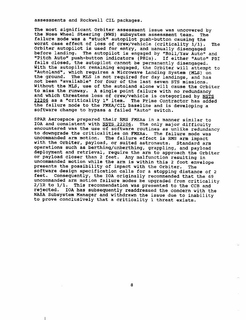
The most significant Orbiter assessment issue was uncovered bythe Nose Wheel Steering (NWS) subsystem assessment team. Thefailure mode was a "stuck" autopilot push-button causing theworst case effect of loss of crew/vehicle (criticality i/i). TheOrbiter autopilot is used for entry, and manually disengagedbefore landing. The autopilot is engaged by "Roll/Yaw Auto" and"Pitch Auto" push-button indicators (PBIs). If either "Auto" PBIfails closed, the autopilot cannot be permanently disengaged.With the autopilot remaining engaged, the Orbiter will attempt to"Autoland", which requires a Microwave Landing System (MLS) onthe ground. The MLS is not required for day landings, and hasnot been "available" for four of the last seven STS missions.Without the MLS, use of the autoland alone will cause the Orbiterto miss the runway. A single point failure with no redundancy
and which threatens loss of crew/vehicle is categorized by NSTS
22206 as a "criticality i" item. The Prime Contractor has added
the failure mode to the FMEA/CIL baseline and is developing a
software change to bypass a failed "Auto" switch.
SPAR Aerospace prepared their RMS FMEAs in a manner similar to
IOA and consistent with NSTS 22206. The only major difficulty
encountered was the use of software routines as unlike redundancyto downgrade the criticalities on FMEAs. The failure mode was
uncommanded arm motion. The failure effect is RMS arm impact
with the Orbiter, payload, or suited astronauts. Standard arm
operations such as berthing/unberthing, grappling, and payload
deployment and retrieval, require the arm to approach the Orbiter
or payload closer than 2 feet. Any malfunction resulting in
uncommanded motion while the arm is within this 2 foot envelope
presents the possibility of impact with the Orbiter. The
software design specification calls for a stopping distance of 2
feet. Consequently, the IOA originally recommended that the 69
uncommanded arm motion failure modes be upgraded from criticality
2/IR to i/I. This recommendation was presented to the CCB and
rejected. IOA has subsequently readdressed the concern with the
NASA Subsystem Manager and withdrawn the issue due to inability
to prove conclusively that a criticality 1 threat exists.
4.0 GENERAL CONCLUSIONS AND OBSERVATIONS
The following paragraphs briefly discuss some of the difficulties
and observations encountered during the IOA study period.
Ground Rules Interpretation - As a result of ambiguous
language used in NSTS 22206, many disagreements arose in
analyzing hardware failure modes. Some of the major sources
of confusion are discussed briefly below for like and unlike
redundancies, redundancy screens, emergency systems, and
crew action and its impact on criticalities.
a. Like and Unlike Redundancy - The interpretation of likeand unlike redundant items and the definition of a
hardware item function are not clearly stated; however,
their impact in assigning functional criticality is
significant. A broad interpretation creates more IR and
2R functional criticalities. And most importantly, the
discussion of parallel functional paths is not adequate
to clarify redundancies. Two examples are discussedbelow.
Example _ - One of the single most important difficulties
encountered during the assessment of the NASA/Rockwell
data was the utilization of multiple scenarios in
assigning functional criticalities. In such cases, the
Rockwell approach seemed to investigate the redundancies
to the effect of the failure of the item under study
instead of redundancies to the item itself. For example,
failure of the supply water system drain Quick Disconnect
(QD) and the drain cap on the supply water system wastied to the failure of the radiators and ammonia boiler
systems in the active thermal control system. This was
apparently done since loss of the flash evaporator system
was seen as an effect of the failure under study, making
it a redundant leg to the radiators and ammonia boiler
systems. In these cases, the functional criticalities
were assigned for potential loss of life/vehicle. The
original IOA interpretation was to make the QD and the
drain cap redundant to each other and then investigate
the functional loss (flash evaporator system) arising
from loss of these redundancies. Based on this approach
a worst case potential for loss of mission was
anticipated by IOA, instead of loss of crew/vehicle.
Example 2 - In certain cases, the Rockwell analysis citesfailure of another item as the cause for the failure of the
item under study. This approach assumes a failure is
already in progress, which seems contrary to the hardware
criticality requirements stated in the NSTS 22206. Under
the hardware criticality requirements only the singular
direct effect of the identified failure mode of a hardware
item is to be investigated.

b. Redundancy Screens - Language such as "...capable of
check out..." for Screen A, and "...from a single credibleevent..." for Screen C leave considerable room for
conjecture on the part of an analyst. Further, the
criteria for complying with the screens are not defined
clearly enough to explain them adequately.
C. Emergency Systems - The definition of emergency systems
excludes hardware items which are used during nominal
mission phases and any intact abort cases. For example,
the Launch Entry Helmet oxygen supply panel and the
Airlock Support System were assigned emergency
status by the subsystem managers. This created a very
conservative approach open to individual interpretation
and not necessarily consistent with the NSTS 22206.
d. Crew Action - The role of crew action in response to a
failure is not clear when assigning hardware criticality
as opposed to functional criticality. Also, the terms
_off-nominal" versus "nominal" versus "contingency", asapplied to crew actions, are used interchangeably
throughout the NSTS 22206, creating confusion.
i0
5.0 RECOMMENDATIONS
Based upon the assessment results and independent study of the
twenty.eight subsystems, the following recommendations are made:
A. The unassociated multiple failure scenarios and failures
already in progress as used by the Orbiter Prime Contractor
should be re-evaluated, since they bring a very broad and
conservative methodology to the FMEA/CIL process. This
approach may reduce visibility into failure modes and
effects for some particular items, since the majority of the
functional criticality 2s and 3s are replaced by IRs and
2Rs, respectively. This approach tends to overload the CIL
with less important failure modes, and prevents the
genuinely significant failure modes from receiving adequate
management attention.
S.
Co
Consideration should be given to improving NSTS 22206 by
eliminating sources of ambiguities. The document should be
rearranged to provide step-by-step procedures and
instructions for conducting hardware failure analysis. This
would reduce guess work and eliminate differences in
philosophy used from one subsystem to another. More
specifically, the topics related to redundancies
(criticality, screens, like/unlike...etc) should be further
expanded to ensure consistent application of methodology and
criticality assignments. The document should provide more
specific examples of application of the ground rules to
specific subsystems.
If NASA and Rockwell maintain their current approach to
redundancy and unrelated failures, confusion could be
avoided in the future by changing the rules in NSTS 22206 so
that they agree with this broader interpretation. Sections
of NSTS 22206 for which changes might be appropriate include
2.3.2.d, 2.3.3.c, and 2.3.3.d.
II
6 • 0 REFERENCES
NSTS 22206 AND RI 100-2G REVIEW
i. Traves, S. T.: FMEA/CIL Instructions and Ground Rules,
I.O-WP-VA86001-01, 14 October 1986
INDEPENDENT ANALYSIS REPORTS
• Drapela, L. J.: Analysis of the Guidance, Navigation, and
Control Subsystem, 1.0-WP-VA86001-16, 19 December 1986
• Robb, B. J.: Analysis of the Data Processing Subsystem,
1.0-WP-VA86001-02, 24 October 1986
• Ewell, J. J.: Analysis of the Backup Flight Subsystem,
1.0-WP-VA86001-18, 8 December 1986
• Hochstein, A. L.: Analysis of the Nose Wheel Steering
Subsystem, 1.0-WP-VA86001-03, 1 November 1986
6. Addis, A. W.: Analysis of the Instrumentation Subsystem,
1.0-WP-VA86001-17, 12 December 1986
• Addis, A. W.: Analysis of the Communication and Tracking
Subsystem, 1.0-WP-VA87001-09, 31 December 1987
. Schmeckpeper, K. R.: Analysis of the Electrical PowerDistribution and Control Subsystem, 1.0-WP-VA86001-28,
3 April 1987
. Schmeckpeper, K. R.: Analysis of the Electrical Power
Distribution and Control / Electrical Power Generation
Subsystem, 1.0-WP-VA86001-19, 19 December 1986
i0. Robinson, W. W.: Analysis of the Electrical Power
Distribution and Control / Remote Manipulator Subsystem,
1.0-WP-VA86001-26, 12 February 1987
ii. Robinson, W. W.: Analysis of the Pyrotechnics Subsystem,
1.0-WP-VA88001-01, 19 January 1988
12. Marino, A. J.: Analysis of the Main Propulsion Subsystem,
1.0-WP-VA86001-22, 6 January 1987
13. Hiott, M. R.: Analysis of the Electrical Power Generation /
Fuel Cell Powerplant Subsystem, 1.0-WP-VA86001-10,
5 December 1986
14. Hiott, M. R.: Analysis of the Electrical Power Generation /
Power Reactant Storage and Distribution Subsystem,
1.0-WP-VA86001-11, 5 December 1986
12

15.
16.
17.
18.
19.
20.
21.
22.
23.
24.
25.
26.
27.
28.
29.
30.
31.
32.
Paul, D. J.: Analysis of the Orbital Maneuvering Subsystem,1.0-WP-VA86001-21, 12 January 1987
Paul, D. J.: Analysis of the Reaction Control Subsystem,1.0-WP-VA86001-27, 19 January 1987
Barnes, J. E.: Analysis of the Auxiliary Power UnitSubsystem, 1.0-WP-VA86001-14, 12 December 1986
Davidson, W. R.: Analysis of the Hydraulics and Water SprayBoiler Subsystems, 1.0-WP-VA86001-20, 15 December 1986
Saiidi, M. J.: Analysis of the Atmospheric RevitalizationSubsystem, 1.0-WP-VA86001-13, 1 December 1986
Saiidi, M. J.: Analysis of the Atmospheric RevitalizationPressure Control Subsystem, 1.0-WP-VA86001-12, 28 November1986
Saiidi, M. J.: Analysis of the Life Support and AirlockSupport Subsystems, 1.0-WP-VA87001-02, 2 November 1987
Raffaelli, G. G.: Analysis of the Extravehicular MobilityUnit, 1.0-WP-VA86001-15, 28 December 1986
Raffaelli, G. G.: Analysis of the Manned Maneuvering Unit
Subsystem, 1.0-WP-VA86001-09, 21 November 1986
Weissinger, W. D.: Analysis of the Landing and Deceleration
Subsystems, I.O-WP-VA86001-25, 19 January 1987
Riccio, J. R.: Analysis of the Ascent Thrust Vector Control
Actuator Subsystem, 1.0-WP-VA86001-06, 21 November 1986
Riccio, J. R.: Analysis of the Elevon Subsystem,
1.0-WP-VA86001-07, 21 November 1986
Riccio, J. R.: Analysis of the Body Flap Subsystem,
1.0-WP-VA86001-05, 21 November 1986
Riccio, J. R.: Analysis of the Rudder/Speed Brake
Subsystem, 1.0-WP-VA86001-04, 21 November 1986
Grasmeder, R. F.: Analysis of the Remote Manipulator
Subsystem, 1.0-WP-VA86001-23, 12 January 1987
Drapela, L. J.: Analysis of the Displays and Control
Subsystem, 1.0-WP-VA86001-16, 19 December 1986
Compton, J. M.: Analysis of the Orbiter and Experiments
Subsystem, 1.0-WP-VA87005, 21 August 1987
Bynum, M. C.: Analysis of the Purge, Vent, and Drain
Subsystem, 1.0-WP-VA87001-04, 18 November 1987
13
33.
34.
35.
Lowery, H. J.: Analysis of the Mechanical ActuationSubsystem, 1.0-WP-VA87001-03, 30 November 1987
Parkman, W. E.: Analysis of the Active Thermal Control
Subsystem, 1.0-WP-VA87001-05, 1 December 1987
Sinclair, S. K.: Analysis of the Crew Equipment Subsystem,
1.0-WP-VA87001-01, 2 November 1987
INDEPENDENT ASSESSMENT REPORTS
36. Trahan, W. H.: Assessment of the Guidance, Navigation, and
Control Subsystem FMEA/CIL, 1.0-WP-VA88003-06, 23 January1988
37.
38.
Trahan, W. H.: Assessment of the Displays and Control
Subsystem FMEA/CIL, 1.0-WP-VA88005-04, 26 January 1988
Robb, B. J.: Assessment of the Data Processing Subsystem
FMEA/CIL, 1.0-WP-VA86001-08, 28 November 1986
39. Ewell, J. J.: Assessment of the Backup Flight Subsystem
FMEA/CIL, 1.0-WP-VA88003-022, ii March 1988
40.
41.
42.
Mediavilla, A. S.: Assessment of the Nose Wheel Steering
Subsystem FMEA/CIL, 1.0-WP-VA86001-21, 20 November 1986
Addis, A. W.: Assessment of the Instrumentation
Subsystem FMEA/CIL, 1.0-WP-VA88003-07, 29 February 1988
Addis, A. W.: Assessment of the Communication and
Tracking Subsystem FMEA/CIL, 1.0-WP-VA88005-010,
21 March 1988
43. Schmeckpeper, K. R.: Assessment of the Electrical Power
Distribution and Control Subsystem FMEA/CIL,
1.0-WP-VA88003-23, 26 February 1988
44.
45.
Schmeckpeper, K. R.: Assessment of the Electrical Power
Distribution and Control/ Electrical Power Generation
Subsystem FMEA/CIL, 1.0-WP-VA88003-34, 1 March 1988
Robinson, W. W.: Assessment of the Electrical Power
Distribution and Control/ Remote Manipulator Subsystem
FMEA/CIL, 1.0-WP-VA88003-35, 8 March 1988
46.
47.
Robinson, W. W.: Assessment of the Pyrotechnics Subsystem
FMEA/CIL, 1.0-WP-VA88005-05, 5 February 1988
McNicoll, W. J.: Assessment of the Main Propulsion
Subsystem FMEA/CIL, 1.0-WP-VA88003-33, 26 February 1988
14
48.
49.
50.
51.
52.
53.
54.
55.
56.
57.
58.
59.
60.
61.
62.
63.
Hiott, M. R.: Assessment of the Electrical PowerGeneration / Fuel Cell Powerplant Subsystem FMEA/CIL,
1.0-WP-VA86001-24, 20 March 1987
Ames, B. E.: Assessment of the Electrical Power
Generation / Power Reactant Supply and Distribution
Subsystem FMEA/CIL, 1.0-WP-VA88003-15, 12 February 1988
Prust, C. D.: Assessment of the Orbital Maneuvering
Subsystem FMEA/CIL, 1.0-WP-VA88003-30, 26 February 1988
Prust, C. D.: Assessment of the Reaction Control Subsystem
FMEA/CIL, 1.0-WP-VA88003-12, 26 February 1988
Barnes, J. E.: Assessment of the Auxiliary Power Unit
Subsystem FMEA/CIL, 1.0-WP-VA88003-10, 19 February 1988
Davidson, W. R.: Assessment of the Hydraulics and Water
Spray Boiler Subsystem FMEA/CIL, 1.0-WP-VA86001-20,
15 December 1986
Saiidi, M. J.: Assessment of the Atmospheric
Revitalization Subsystem FMEA/CIL, 1.0-WP-VA88003-025,
26 February 1988
Saiidi, M. J.: Assessment of the Atmospheric Revitalization
Pressure Control Subsystem FMEA/CIL, 1.0-WP-VA88003-09,
19 February 1988
Saiidi, M. J.: Assessment of the Life Support and Airlock
Support Subsystems, 1.0-WP-VA88003-19, 26 February 1988
Saiidi, M. J.: Assessment of the Manned Maneuvering Unit
Subsystem FMEA/CIL, 1.0-WP-VA88003-11, 19 February 1988
Raffaelli, G. G.: Assessment of the Extravehicular
Mobility Unit Subsystem FMEA/CIL, 1.0-WP-VA88003-37,i0 March 1988
Weissinger, W. D.: Assessment of the Landing and
Deceleration Subsystem FMEA/CIL, 1.0-WP-VA88003-039,i0 March 1988
Wilson, R. E.: Assessment of the Ascent Thrust Vector
Control Actuator Subsystem FMEA/CIL, 1.0-WP-VA88003-03,
5 February 1988
Wilson, R. E.: Assessment of the Elevon Actuator Subsystem
FMEA/CIL, 1.0-WP-VA88003-05, 05 February 1988
Wilson, R. E.: Assessment of the Body Flap Subsystem
FMEA/CIL, 1.0-WP-VA88003-04, 05 February 1988
Wilson, R. E.: Assessment of the Rudder/Speed Brake
Subsystem FMEA/CIL, 1.0-WP-VA88003-08, 05 February 1988
15

64. Grasmeder, R. F.: Assessment of the Remote ManipulatorSubsystem FMEA/CIL, 1.0-WP-VA88003-16, 26 February 1988
65. Compton, J. M.: Assessment of the Orbiter and ExperimentSubsystem FMEA/CIL, 1.0-WP-VA88005-03, 5 February 1988
66. Bynum, M. C.: Assessment of the Purge, Vent, and DrainSubsystem FMEA/CIL, 1.0-WP-VA88005-02, 5 February 1988
67. Lowery, H. J.: Assessment of the Mechanical ActuationSubsystem FMEA/CIL, 1.0-WP-VA88003-09, 19 February 1988
68. Sinclair, S. K.: Assessment of the Active Thermal ControlSubsystem FMEA/CIL, 1.0-WP-VA88005-06, 12 February 1988
69. Sinclair, S. K.: Assessment of the Crew EquipmentSubsystem FMEA/CIL, 1.0-WP-VA88005-07, 12 February 1988
70. Independent Orbiter Assessment FMEA/CIL Assessment InterimReport, 1.0-WP-VA88003-40, 9 March 1988
71. Independent Orbiter Assessment CIL Issues Resolution Report,I.O-WP-VA88003-48, 16 September 1988
16

APPENDIX A
ACRONYMS
A-I

ACRONYMS
ABS
ACA
ACIP
ADI
ADP
ADS
ADTA
ALCA
AMCA
AOA
AOS
APC
APU
ARCS
ARPCS
ARS
ASA
ATCS
ATO
ATVC
B&AS
BF
BFC
BFS
BITE
C&W
CCB
CCC
CCTV
CCU
CIL
CIU
CNTLR
COAS
COMM
CPU
CRIT
CWS
D&C
DAP
DCM
DCN
DDU
DEU
DFI
DHE
DMA
DOD
DPS
DSC
- Ammonia Boiler System
- Annunciator Control Assembly
- Aerodynamic Coefficient Instrumentation Package- Attitude Direction Indicator
- Air Data Probe
- Audio Distribution System
- Air Data Transducer Assembly
- Aft Load Control Assembly
- Aft Motor Control Assembly- Abort-Once-Around
- Acquisition of Signal- Aft Power Controller
- Auxiliary Power Unit
- Aft Reaction Control System (Subsystem)
- Atmospheric Revitalization Pressure Control System
- Atmospheric Revitalization System
- Aerosurface Servo Amplifier
- Active Thermal Control Subsystem
- Abort-To-Orbit
- Ascent Thrust Vector Control
- Brakes and Antiskid
- Body Flap
- Backup Flight Control
- Backup Flight System
- Built-In Test Equipment
- Caution and Warning
- Change Control Board
- Contaminant Control Cartridge- Closed-Circuit Television
- Crew Communications Umbilical
- Critical Items List
- Communications Interface Unit
- Controller
- Crew Optical Alignment Sight
- Communication
- Central Processing Unit
- Criticality
- Caution and Warning System
- Displays and Controls
- Digital Autopilot
- Display and Control Module
- Document Change Notice
- Display Driver Unit
- Display Electronic Unit
- Development Flight Instrumentation
- Data-Handling Electronics
- Deployed Mechanical Assembly
- Department of Defense
- Data Processing System (Subsystem)
- Dedicated Signal Conditioner
A-2
ACRONYMS
ECLSS
EI
EIU
EMU
EPA
EPDC
EPG
EPS
ET
EVA
EVCS
FC
FCA
FCB
FCL
FCOS
FCP
FCS
FDA
FDM
FES
FFSSO
FLCA
FM
FMCA
FMD
FMEA
FPC
FRCS
FSM
FSS
FSSR
FSW
GAS
GFE
GMT
GNC
GPC
GSE
GSTDN
HDC
HEX
HIRAP
HIU
HPFTP
HPOT
HUT
HW
HX
HYD
- Environmental Control and Life Support System (Subsystem)
- Entry Interface
- Engine Interface Unit
- Extravehicular Mobility Unit
- Environmental Protection Agency
- Electrical Power, Distribution and Control
- Electrical Power Generator
- Electrical Power System
- External Tank
- Extravehicular Activity
- Extravehicular Communications System- Fuel Cell
- Flow Control Assembly
- Fecal Collection Bag
- Freon Coolant Loop
- Flight Control Operating System
- Fuel Cell Power (Plant)
- Flight Control System- Fault Detection and Annunciation
- Frequency Division Multiplexing
- Flash Evaporator System
- Forward Fuselage Support System for OEX
- Forward Load Control Assembly- Failure Mode
- Forward Motor Control Assembly
- Frequency Division Multiplexer
- Failure Modes and Effects Analysis- Forward Power Controller
- Forward Reaction Control System (Subsystem)
- Fault Summary Message
- Flight Support Structure
- Flight Systems Software Requirements
- Flight Software
- Get-Away Special
- Government Furnished Equipment- Greenwich Mean Time
- Guidance, Navigation, and Control
- General Purpose Computer
- Ground Support Equipment
- Ground Spaceflight Tracking and Data Network
- Hybrid Driver Controller
- Heat Exchanger
- High-Resolution Accelerometer Package
- Headset Interface Unit
- High-Pressure Fuel Turbopump
- High-Pressure Oxidizer Turbopump
- Hard Upper Torso
- Hardware
- Heat Exchanger
- Hydraulics
A-3
ACRONYMS
ICM
ICMS
ICOM
ICRS
IFM
IMU
IOA
IOM
IUS
IVA
JSC
KBD
LCA
LCC
LCVG
LDG/DEC
LEH
LPS
LRU
LSS
LTA
MADS
MAS
MCA
MCC
MCDS
MDAC
MDM
MEC
MECO
MET
MGSSA
MIA
MLG
MM
MMU
MMU
MPL
MPM
MPS
MS
MSBLS
MSK
MTU
MUX
NASA
NGSSA
NGTD
NLG
NSI
- Interface Control Module
- Intercom Master Station
- Intercommunications
- Intercom Remote Station
- In-Flight Maintenance- Inertial Measurement Unit
- Independent Orbiter Assessment
- Input/Output Module
- Inertial Upper Stage
- Intravehicular Activity
- Johnson Space Center
- Ku-Band Deploy
- Load Controller Assembly- Launch Control Center
- Liquid Cooling and Ventilation Garment
- Landing and Deceleration
- Launch/Entry Helmet
- Launch Processing System
- Line Replaceable Unit
- Life Support Subsystem
- Lower Torso Assembly
- Modular Auxiliary Data System
- Mechanical Actuation System
- Motor Control Assembly
- Mission Control Center (JSC)
- Multifunction CRT Display System
- McDonnell Douglas Astronautics Company
- Multiplexer/Demultiplexer
- Main Engine Controller
- Main Engine Cutoff
- Mission Elapsed Time
- Main Gear Shock Strut Assembly
- Multiplexer Interface Adapter
- Main Landing Gear
- Major Mode
- Manned Maneuvering Unit
- Mass Memory Unit
- Minimum Power Level (65%)
- Manipulator Positioning Mechanism
- Main Propulsion System (Subsystem)
- Mission Specialist
- Microwave Scanning Beam Landing System
- Manual Select Keyboard
- Master Timing Unit
- Multiplex
- National Aeronautics and Space Administration
- Nose Landing Gear Shock Strut Assembly- Nose Gear Touch Down
- Nose Landing Gear- NASA Standard Initiator
A-4

NSPNSTSNWSOBSOEXOIOMRSD
OMSOTBOWDAP/LPASSPBIPBMPCAPCIPCMPCMMUPCNPCSPDUPFRPHSPIPICPLBPLBDPLSPLSSPMSPRCBPRCBDPRCSPRDPROMPRSDPRSDSPSAPSAPSPPTTPV&DQDR/BPARAMRCSRFCARFIRGA
ACROMYMS
- Network Signal Processor- National Space Transportation System- Nose-Wheel Steering- Operational Bioinstrumentation System- Orbiter Experiments- Operational Instrumentation- Operational Maintenance Requirements &
Specifications Document- Orbital Maneuvering System- Orbiter Timing Buffer- Operational Water Dispenser Assembly- Payload- Primary Avionics Software System- Push-Button Indicator- Payload Bay Mechanical- Power Control Assembly- Potential Critical Item
- Pulse Code Modulation
- Pulse Code Modulation Master Unit
- Page Change Notice
- Pressure Control System- Power Drive Unit
- Portable Foot Restraint
- Personal Hygene Station
- Payload Interrogater
- Pyro Initiator Controller
- Payload Bay
- Payload Bay Door
- Primary Landing Site
- Portable Life Support Subsystem
- Propellant Management Subsystem
- Program Requirements Control Board
- Program Requirements Control Board Directive
- Primary Reaction Control System (jet)
- Payload Retention Device
- Programmable Read-Only Memory
- Power Reactant Storage and Distribution
- Power Reactant Storage and Distribution System
- Power Section Assembly
- Provision Stowage Assembly
- Payload Signal Processor- Push-to-talk
- Purge Vent & Drain
- Quick Disconnect
- Rudder/Pedal Brake Assembly
- Random Access Memory
- Reaction Control System
- Radiator and Flow Control Assembly
- Radio Frequency Interference
- Rate Gyro Assembly
A-5

ACRONYMS
RHC
RHS
RI
RJD
RM
RMS
RPA
RPC
RPTA
RSB
RTD
RTLS
RTS
RVDT
SBTC
SCB
SCM
SCU
SCU
SDM
SEADS
SFOM
SFP
SGLS
SILTS
SM
SMM
SOP
SOS
SPA
SPFA
SPI
SRB
SSA
SSME
SSMEC
SSO
SSSH
ST
STDN
STS
TACAN
TAL
TCS
TD
TDRS
THC
THC
TPS
TVC
- Rotation Hand Controller
- Rehydration Station
- Rockwell International
- Reaction Jet Driver
- Redundancy Management
- Remote Manipulator System
- Ruder Pedal Assembly- Remote Power Controller
- Rudder Pedal Transducer Assembly
- Rudder Speed Brake
- Resistance Temperature Device- Return-to-Launch Site
- Remote Tracking Station
- Rotary Variable Differential Transformer
- Speed Brake Translation Controller
- Steering Control Box
- System Control Module
- Sequence Control Unit
- Service and Cooling Umbilical- Startracker Door Mechanism
- Shuttle Entry Air Data System
- Shuttle Flight Operations Manual
- Single Failure Point
- Space Ground Link System
- Shuttle Infrared Leeside Temperature Sensor
- Systems Management
- Solar Maximum Mission
- Secondary Oxygen Pack
- Space Operations Simulator
- Steering Position Amplifier
- Single Point Failure Analysis
- Surface Position Indicator
- Solid Rocket Booster
- Space Suit Assembly
- Space Shuttle Main Engine- SSME Controller
- Space Shuttle Orbiter
- Space Shuttle Systems Handbook- Star Tracker
- Spaceflight Tracking and Data Network
- Space Transportation System
- Tactical Air Navigation
- Transatlantic Abort Landing
- Thermal Control System (Subsystem)- Touch Down
- Tracking and Data Relay Satellite- Thruster Hand Controller
- Translation Hand Controller
- Thermal Protection System
- Thrust Vector Control
A-6

UCD
UEA
UHF
VDM
VRCS
WBSC
WCCS
WCCU
WMS
WP
WRS
WSB
ACRONYMS
- Urine Collection Device
- Unitized Electrode Assembly
- Ultra High Frequency- Vent Door Mechanism
- Vernier Reaction Control System (jet)
- Wide-Band Signal Conditioner
- Window Cavity Conditioning System- Wireless Crew Communications Umbilical
- Waste Management System
- Working Paper
- Water Removal Subsystem
- Water Spray Boiler
A-7


APPENDIX B
DEFINITIONS, GROUND RULES, AND ASSUMPTIONS
B.I
B.2
Definitions
Project Level Ground Rules and Assumptions
B-I

APPENDIX B
DEFINITIONS, GROUND RULES, AND ASSUMPTIONS
B.I Definitions
Definitions contained in NSTS 22206, Instructions For Preparation
of FMEA/CIL, were used with the following amplifications andadditions.
INTACT ABORT DEFINITIONS:
RTLS - begins at transition to OPS 6 and ends at transition
to OPS 9, post-flight
TAL - begins at declaration of the abort and ends at
transition to OPS 9, post-flight
AOA - begins at declaration of the abort and ends at
transition to OPS 9, post-flight
ATO - begins at declaration of the abort and ends at
transition to OPS 9, post-flight
CREDIBLE (CAUSE) - an event that can be predicted or expected inanticipated operational environmental conditions. Excludes an
event where multiple failures must first occur to result in
environmental extremes
CONTINGENCY CREW PROCEDURES - procedures that are utilized beyond
the standard malfunction procedures, pocket checklists, and cuecards
EARLY MISSION TERMINATION - termination of onorbit phase prior toplanned end of mission
EFFECTS/RATIONALE - description of the case which generated the
highest criticality
HIGHEST CRITICALITY - the highest functional criticality
determined in the phase-by-phase analysis
MAJOR MODE (MM) - major sub-mode of software operational sequence
(ops)
M C - Memory Configuration of Primary Avionics Software System
(PASS)
MISSION - assigned performance of a specific Orbiter flight with
payload/objective accomplishments including orbit phasing and
altitude (excludes secondary payloads such as GAS cans,
middeck P/L, etc.)
B-2

MULTIPLE ORDER FAILURE - describes the failure due to a single
cause or event of all units which perform a necessary (critical)
function
OFF-NOMINAL CREW PROCEDURES - procedures that are utilized beyond
the standard malfunction procedures, pocket checklists, and cue
cards
OPS - software operational sequence
PRIMARY MISSION OBJECTIVES - worst case primary mission objec-
tives are equal to mission objectives
PHASE DEFINITIONS:
PRELAUNCH PHASE - begins at launch count-down Orbiter
power-up and ends at moding to OPS Major Mode 102 (liftoff)
LIFTOFF MISSION PHASE - begins at SRB ignition (MM 102) and
ends at transition out of OPS 1 (Synonymous with ASCENT)
ONORBIT PHASE - begins at transition to OPS 2 or OPS 8 andends at transition out of OPS 2 or OPS 8
DEORBIT PHASE - begins at transition to OPS MSjor Mode
301 and ends at first main landing gear touchdown
LANDING/SAFING PHASE - begins at first main gear
touchdown and ends with the completion of post-landing
safing operations
B-3

APPENDIX B
DEFINITIONS, GROUND RULES, AND ASSUMPTIONS
B.2 IOA Project Level Ground Rules and Assumptions
The philosophy embodied in NSTS 22206, Instructions for
Preparation of FMEA/CIL, was employed with the following
amplifications and additions•
i.
•
•
•
•
The operational flight software is an accurate
implementation of the Flight System Software Requirements
(FSSRs) .
RATIONALE: Software verification is out-of-scope ofthis task.
After liftoff, any parameter which is monitored by system
management (SM) or which drives any part of the Caution and
Warning System (C&W) will support passage of Redundancy
Screen B for its corresponding hardware item.
RATIONALE: Analysis of on-board2arameter availability
and/or the actual monitoring by the crew
is beyond the scope of this task.
Any data employed with flight software is assumed to be
functional for the specific vehicle and specific mission
being flown.
RATIONALE: Mission data verification is out-of-scope ofthis task.
All hardware (including firmware) is manufactured and
assembled to the design specifications/drawings.
RATIONALE: Acceptance and verification testing is
designed to detect and identify problems
before the item is approved for use.
All Flight Data File crew procedures will be assumed
performed as written, and will not include human error in
their performance.
RATIONALE: Failures caused by human operational error
are out-of-scope of this task.
B-4

,
•
•
•
i0.
ii.
All hardware analyses will, as a minimum, be performed at
the level of analysis existent within NASA/Prime Contractor
Orbiter FMEA/CILs, and will be permitted to go to greaterhardware detail levels but not lesser•
RATIONALE: Comparison of IOA analysis results with
other analyses requires that both analyses
be performed to a comparable level ofdetail.
Verification that a telemetry parameter is actually
monitored during AOS by ground-based personnel is not
required.
RATIONALE: Analysis of mission-dependent telemetry
availability and/or the actual monitoring of
applicable data by ground-based personnel is
beyond the scope of this task.
The determination of criticalities per phase is based on the
worst case effect of a failure for the phase being analyzed.
The failure can occur in the phase being analyzed or in
any previous phase, whichever produces the worst case
effects for the phase of interest.
RATIONALE: Assigning phase criticalities ensures a
thorough and complete analysis.
Analysis of wire harnesses, cables, and electrical connectors
to determine if FMEAs are warranted will not be performed
nor FMEAs assessed•
RATIONALE: Analysis was substantially complete prior
to NSTS 22206 ground rule redirection.
Analysis of welds or brazed joints that cannot be inspected
will not be performed nor FMEAs assessed.
RATIONALE: Analysis was substantially complete prior
to NSTS 22206 ground rule redirection•
Emergency system or hardware will include burst discs and
will exclude the EMU Secondary Oxygen Pack (SOP), pressure
relief valves and the landing gear pyrotechnics.
RATIONALE: Clarify definition of emergency systems to
ensure consistency throughout IOA project.
B-5

APPENDIX C
SUBSYSTEM ASSESSMENT SUMMARIES
Section
C.l
C.2
C.3
C.4
C.5
C.6
C.7
C.8
C.9
C.10
C.II
C.12
C.13
C.14
C.15
C.16
C.17
C.18
C.19
C.20
C.21
C.22
C.23
C.24
C.25
C.26
C.27
C.28
Subsystem Asssessment Overview
Fuel Cell Powerplant
Hydraulic Actuators
Displays and Control
Guidance, Navigation and Control
Orbiter Experiments
Auxiliary Power Unit
Backup Flight SystemElectrical Power Distribution &
Control
Landing and Deceleration
Purge, Vent and Drain
Pyrotechnics
Active Thermal Control System and
Life Support System
Crew EquipmentInstrumentation
Data Processing System
Atmospheric Revitalization Pressure
Control System
Hydraulics and Water Spray Boiler
Mechanical Activation System
Manned Maneuvering Unit
Nose Wheel Steering
Remote Manipulator System
Atmospheric Revitalization System
Extravehicular Mobility Unit
Power Reactant Supply and
Distribution System
Main Propulsion System
Orbital Maneuvering System
Reaction Control System
Comm and Tracking
paqe
C-2
C-2
C-8
C-10
C-10
C-10
C-14
C-17
C-17
C-20
C-23
C-25
C-30
C-30
C-30
C-34
C-35
C-35
C-38
C-41
C-43
C-44
C-47
C-50
C-52
C-55
C-60
C-65
C-I
APPENDIX CSUBSYSTEMASSESSMENTSUMMARIES
The IOA assessments proved a valuable method of ensuring the
proper criticality level be assigned to each FMEA/CIL identified.
In many cases the assigned criticality level was changed by the
appropriate subsystem manager due to the IOA assessment. As a
minimum, this assessment created a deeper awareness of the
criticality level assigned and better rationale and
understanding. Differences in interpretation and level of detail
caused many of the issues generated, along with the lack of
updated NASA FMEA/CIL packages. Many non-critical issues remain
which should be resolved by the subsystem managers.
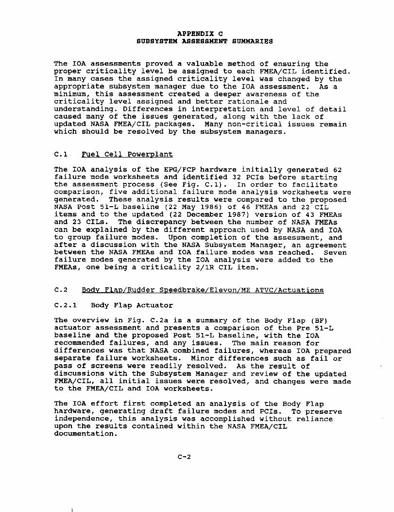
C.I Fuel Cell Powerplant
The IOA analysis of the EPG/FCP hardware initially generated 62
failure mode worksheets and identified 32 PCIs before starting
the assessment process (See Fig. C.l). In order to facilitate
comparison, five additional failure mode analysis worksheets were
generated. These analysis results were compared to the proposed
NASA Post 51-L baseline (22 May 1986) of 46 FMEAs and 22 CIL
items and to the updated (22 December 1987) version of 43 FMEAs
and 23 CILs. The discrepancy between the number of NASA FMEAs
can be explained by the different approach used by NASA and IOA
to group failure modes. Upon completion of the assessment, and
after a discussion with the NASA Subsystem Manager, an agreementbetween the NASA FMEAs and IOA failure modes was reached. Seven
failure modes generated by the IOA analysis were added to the
FMEAs, one being a criticality 2/IR CIL item.
C.2 Body Flap/Rudder Speedbrake/Elevon/ME ATVC/Actuations
C.2.1 Body Flap Actuator
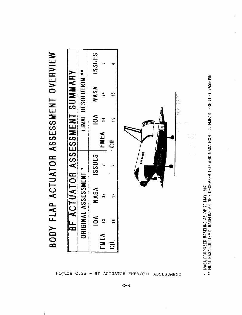
The overview in Fig. C.2a is a summary of the Body Flap (BF)
actuator assessment and presents a comparison of the Pre 51-L
baseline and the proposed Post 51-L baseline, with the IOA
recommended failures, and any issues. The main reason for
differences was that NASA combined failures, whereas IOA prepared
separate failure worksheets. Minor differences such as fail or
pass of screens were readily resolved. As the result of
discussions with the Subsystem Manager and review of the updated
FMEA/CIL, all initial issues were resolved, and changes were made
to the FMEA/CIL and IOA worksheets.
The IOA effort first completed an analysis of the Body Flap
hardware, generating draft failure modes and PCIs. To preserve
independence, this analysis was accomplished without reliance
upon the results contained within the NASA FMEA/CILdocumentation.
C-2

ILl
00um
Z
u C3
.... _/ .............
i
u__2
:: /:
Figure C.I - EPG/FCP FMEA/CIL ASSESSMENT
C-3
_o
r% n-
,_ r_-
o
(_9 .--
_u Oz
&AJ
(;9 U_Z
:% W
O "
O-O"" <O. Z
*f Z
. 2,
Z111
Z
o_
&OuJ
O0O_i
_zu.
N u.
Figure C.2a - BF ACTUATOR FMEA/CIL ASSESSMENT
i̧
H
W
z-n
..J
(;9
LJ-
._J
i
z0Z
O9
Z
Z
m-..¢oo">
OC
03
,.,=,
.....-m LU,_. ,-..%
>_ ,....
"_u..
L,_
¢,nLUI'--
0
rr'._13-'7
ZC"
C-4
The IOA analysis of the BF hardware initially generated 36 failure
mode worksheets and identified 19 PCIs before starting the assess-
ment process. In order to facilitate comparison, seven additional
failure mode analysis worksheets were generated.
The IOA results were then compared to the NASA FMEA/CIL baseline
with proposed Post 51-L updates included. A resolution of each
discrepancy from the comparison was provided through additional
analysis as required. Upon completion of the assessment, all of
the IOA and NASA failure modes were in agreement.
C.2.2 Rudder/Speedbrake Actuator
The overview in Fig. C.2b is a summary of the Rudder/Speed Brake
(RSB) actuator assessment and presents a comparison of the Pre
51-L baseline and the proposed Post 51-L baseline, with the IOA
recommended failures, and any issues. The main reason for
differences was that NASA combined failures, whereas IOA prepared
separate failure worksheets. Minor differences such as fail or
pass of screens were readily resolved. As the result of
discussions with the Subsystem Manager and review of the updated
FMEA/CIL, all initial issues were resolved, and changes were made
to the FMEA/CIL and IOA worksheets.
The IOA effort first completed an analysis of the RSB hardware,
generating draft failure modes and PCIs. To preserve
independence, this analysis was accomplished without reliance
upon the results contained within the NASA FMEA/CIL
documentation.
The IOA analysis of the RSB hardware initially generated 38
failure mode worksheets and identified 27 PCIs before starting
the assessment process. No additional failure mode worksheets
were generated during the comparison. The IOA results were
then compared to the NASA FMEA/CIL baseline, with the proposed
Post 51-L CIL updates included. A resolution of each discrepancy
produced by the comparison was provided through additional
analysis as required. Upon completion of the assessment, all
of the IOA and NASA failure modes were in agreement.
C.2.3 Elevon Actuator
The overview in Fig. C.2c is a summary of the elevon actuator
assessment and presents a comparison of the Pre 51-L baseline and
the proposed Post 51-L baseline, with the IOA recommended
failures, and any issues. The main reason for differences was
that NASA combined failures, whereas IOA prepared separate
failure worksheets. Minor differences such as fail or pass of
screens were readily resolved. As the result of discussions with
the Subsystem Manager and review of the updated FMEA/CIL all
initial issues were resolved, and changes were made to the
FMEA/CIL and IOA worksheets.
The IOA effort first completed an analysis of the elevon subsystem
C-5
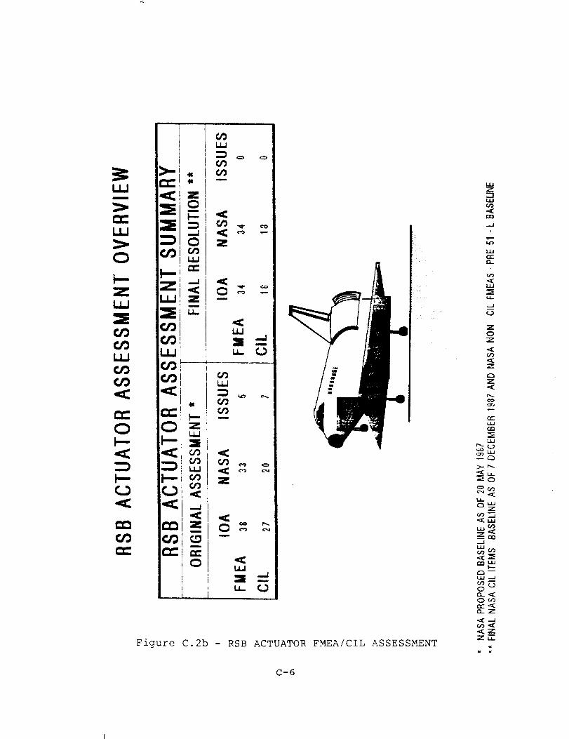
Figure C.2b - RSB ACTUATOR FMEA/CIL ASSESSMENT
z-1
..JI
w--L4_
_c
i
(29
u&.
--J
(.)!
ZOZ
z
L.u
OuaZ
0") "n
k,kl _')
,-.1
e_CO
0
O..Z
"_Zz_.
c-6
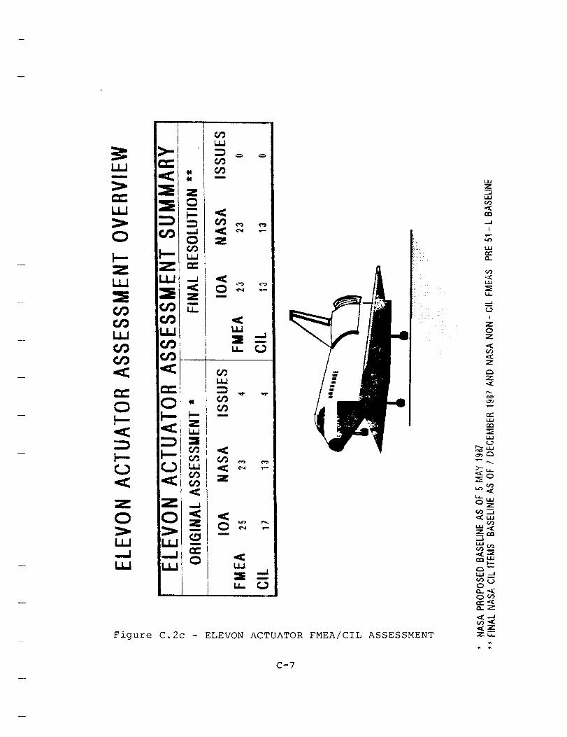
Figure C.2c - ELEVON ACTUATOR FMEA/CIL ASSESSMENT
C-7
Wz-n
(;9
..4
L4J
CU
!
(,O
U-
-J
[
ZOZ
Z
Z
*X
m.
W
C_
U&/
>-u_
_O
o_uz
(;9 ..J
_w
_w
C3_
O
_.z
hardware, generating draft failure modes and PCIs. To preserve
independence, this analysis was accomplished without reliance upon
the results contained within the NASA FMEA/CIL documentation. The
IOA analysis of the elevon actuator hardware initially generated 25
failure mode worksheets and identified 17 PCIs before starting the
assessment process. No additional failure mode worksheets were
generated during the comparison. The analysis results were
compared to the proposed NASA Post 51-L baseline of 23 FMEAs and 13
CIL items. A resolution of each discrepancy from the comparison
was provided through additional analysis as required. Upon
completion of the assessment, all of the IOA and NASA failure modes
were in agreement.
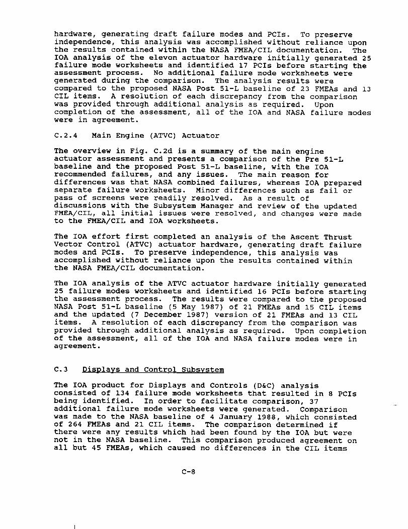
C.2.4 Main Engine (ATVC) Actuator
The overview in Fig. C.2d is a summary of the main engine
actuator assessment and presents a comparison of the Pre 51-L
baseline and the proposed Post 51-L baseline, with the IOA
recommended failures, and any issues. The main reason for
differences was that NASA combined failures, whereas IOA prepared
separate failure worksheets. Minor differences such as fail or
pass of screens were readily resolved. As a result of
discussions with the Subsystem Manager and review of the updated
FMEA/CIL, all initial issues were resolved, and changes were made
to the FMEA/CIL and IOA worksheets.
The IOA effort first completed an analysis of the Ascent Thrust
Vector Control (ATVC) actuator hardware, generating draft failure
modes and PCIs. To preserve independence, this analysis was
accomplished without reliance upon the results contained within
the NASA FMEA/CIL documentation.
The IOA analysis of the ATVC actuator hardware initially generated
25 failure modes worksheets and identified 16 PCIs before starting
the assessment process. The results were compared to the proposed
NASA Post 51-L baseline (5 May 1987) of 21 FMEAs and 15 CIL items
and the updated (7 December 1987) version of 21 FMEAs and 13 CIL
items. A resolution of each discrepancy from the comparison was
provided through additional analysis as required. Upon completion
of the assessment, all of the IOA and NASA failure modes were in
agreement.
C.3 Displays and Control Subsystem
The IOA product for Displays and Controls (D&C) analysisconsisted of 134 failure mode worksheets that resulted in 8 PCIs
being identified. In order to facilitate comparison, 37
additional failure mode worksheets were generated. Comparison
was made to the NASA baseline of 4 January 1988, which consisted
of 264 FMEAs and 21 CIL items. The comparison determined if
there were any results which had been found by the IOA but were
not in the NASA baseline. This comparison produced agreement on
all but 45 FMEAs, which caused no differences in the CIL items
C-8
U_u
=
.__. _--
Zm
zU_
Zm
Figure C.2d - MAIN ENGINE ACTUATOR FMEA/CIL ASSESSMENT
u_Z-1UU
_JI
[
W
..J
i
ZOZ
z
z<Er,.,.oo
LIJ
rn
LII
P" LIJ
>" LI.
QwZ
-.I
0
,_ZzE
C-9

(reference Figure C.3).
The issues arose due to different interpretation of NSTS 22206,
the FMEA and CIL preparation instructions. IOA analyzed the
electrical circuits as black boxes, and NASA analyzed the
components within the black boxes. Of the 45 differences with
the FMEAs, all were minor and did not affect criticality
assessments. In conclusion, IOA is in full agreement with the
revised NASA CIL baseline.
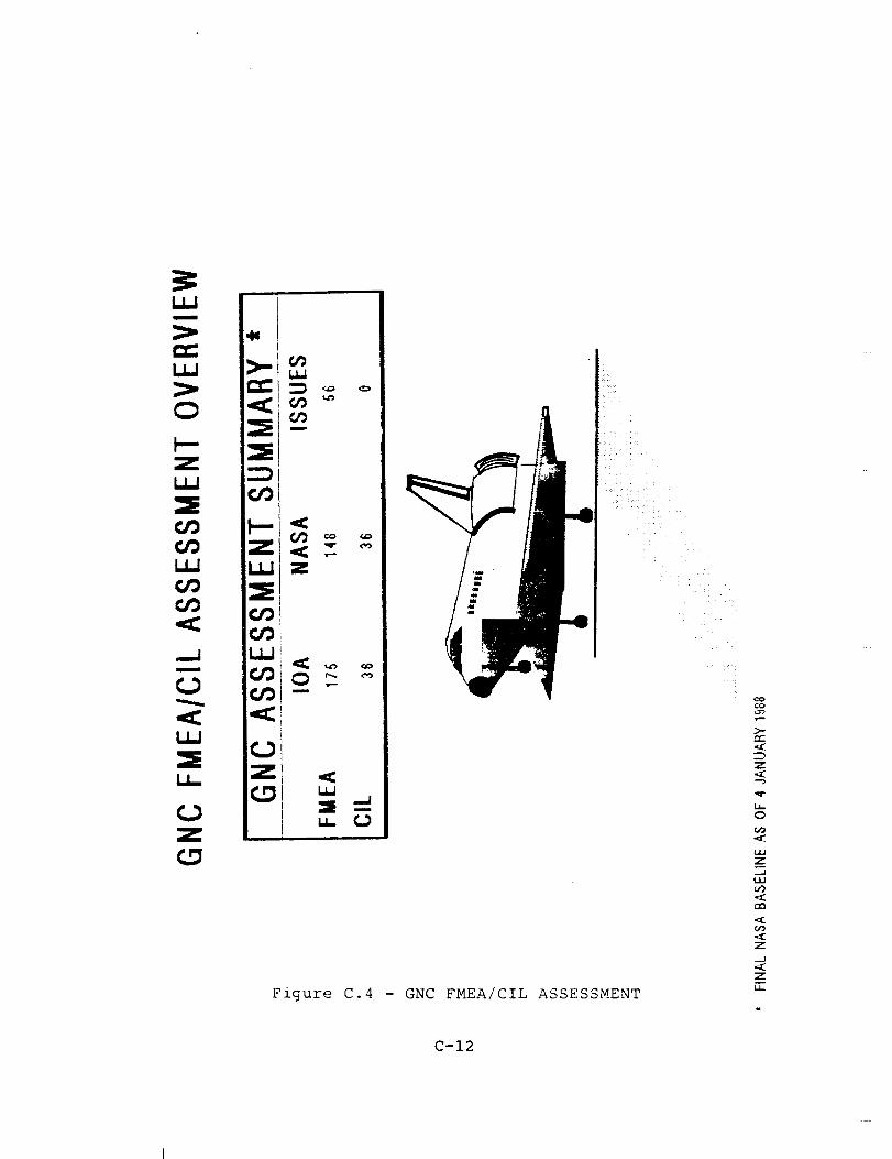
C.4 Guidance, Naviqation and Control System
The IOA product for the Guidance, Navigation and Control (GNC)
analysis consisted of 141 failure mode worksheets that resulted
in 24 PCIs being identified. In order to facilitate comparison,
34 additional failure mode worksheets were generated. Comparison
was made to the NASA baseline (as of 4 January 1988) which
consisted of 148 FMEAs and 36 CIL items. The comparison
determined if there were any results which had been found by the
IOA that were not in the NASA baseline. This comparison produced
agreement on all but 56 FMEAs, with no differences in CIL items
(reference Figure C.4).
The issues arose due to different interpretation of NSTS 22206,
the FMEA and CIL preparation instructions. IOA analyzed the
components of the electrical circuits, generating 56 worksheets
more than NASA, who treated the electrical circuits as black
boxes. Of these 56 differences with the FMEAs, all were minor
and did not affect criticality assessments. Three of the FMEA
issues were with the Solid Rocket Booster Rate Gyro Assembly
EPD&C. No drawings were available to assess these FMEAs. In
conclusion, IOA is in full agreement with the revised NASA CILbaseline.
C.5 Orbiter Experiments
The IOA analysis of the Orbiter Experiments (OEX) hardware
initially generated 82 failure mode worksheets and identified 2
PCIs before starting the assessment process (Fig. C.5). These
analysis results were compared to the proposed NASA Post 51-L
baseline of 191 FMEAs and 1 CIL item, which was generated using
the older FMEA/CIL instructions. Upon completion of the
assessment, 167 of the 191 FMEAs were in agreement. Of the 24
that remained, 21 were IOA 3/3 FMEAs on components not addressed
by NASA. Of the remaining three, two issues were with FMEA
criticality levels. The remaining issue concerned a FMEA on a
component which no longer exists; thus, no FMEA was needed, and
the issue was withdrawn.
C.6 Auxiliary Power Unit
Comparison of the IOA Auxiliary Power Unit (APU) analysis product
C-10

>-
ZuJ
_9U_
_9
Z
u_l =-
Figure C.3 - D&C FMEA/CIL ASSESSMENT
c6
>-
Z
_T
U-
O
(,'3
LAJ
_z
OO
O_
Z
.-J
-xz
C-ll
m
Figure C.4 - GNC FMEA/CIL ASSESSMENT
¢o
>..
Z
.,_
o
L4,.,I
z_..ILLI
0'3.
O0
Z
_J
1.1,.
C-12
UWu
UJ
O
Z
XU_
O
zio_
O
U_
Zm
U-
XU_
O
Z
m
un
u_
_91 Z&O
m
z --u_
Figure C.5 - OEX FMEA/CIL ASSESSMENT
co
z
o.-_
u._O
".2"_ UU
a:_ "-n
u,_ ...x
0
Oco,,.,,- .<(l.z
C-13

with the NASA APU FMEA/CIL baseline which emerged from the NASA
FMEA/CIL review process produced numerous discrepancies.
Discussions of these discrepancies with the NASA Subsystem
Manager resulted in the identification of 28 issues, which were
taken to the NASA/Rockwell FMEA review working group meetingsfor consideration. These reviews resulted in the addition of
four new hardware FMEAs to the APU FMEA baseline, three of whichare CIL items.
Two IOA issues remain for the APU subsystem at the completion of
the assessment (Fig. C.6). The first issue is a carryover from
the original 28 issues, and involves a fuel line temperature
sensor which is not covered by the existing FMEA baseline. The
APU Subsystem Manager agreed that this sensor, the fuel pump
bypass line temperature sensor (MDAC ID 417X), should be covered
since loss of it could lead to curtailment of orbit activities
(if one other sensor is lost), but stated that consideration of
APU instrumentation FMEAs had been deferred indefinitely to allow
completion of the review of higher-criticality FMEAs. IOA
recommends adding a FMEA to cover failure of this sensor at
criticality 3/2R. IOA recommends a criticality of 3/IR for FMEA
04-2-518A-2 (lube oil heater thermostat failed closed), to
match the effect of possible loss of an APU due to lube oil over-
heating cited in APU electrical FMEAs 05-6N-2048-2, 05-6N-2050-2,
and 05-6N-2051-2. This discrepancy between hardware FMEAs and
electrical FMEAs did not emerge during the initial assessment ofthe hardware FMEAs.
C.7 Backup Fliqht System
The IOA product for the Backup Flight System (BFS) analysisconsisted of 29 failure mode worksheets that resulted in 21
PCIs being identified. This product was originally compared with
the proposed NASA BFS baseline as of October 1986, and
subsequently compared with the applicable (as of 19 November
1987) Data Processing System (DPS), Electrical Power Distribution
and Control (EPD&C), and Displays and Controls NASA CIL items.
The comparisons determined if there were any results which had
been found by the IOA that were not in the NASA baseline.
The original assessment determined there were numerous failure
modes and PCIs in the IOA analysis that were not contained in the
NASA BFS baseline. Conversely, the NASA baseline contained three
FMEAs (Inertial Measurement Unit (IMU), Air Data Transducer
Assembly (ADTA), and Air Data Probe) for CIL items that were not
identified in the IOA product. The IOA prepared worksheets and
agreed with the NASA analysis for the three items. This
increased the IOA worksheets from 29 to 32 and the PCIs from 21
to 24 for the original assessment as shown in Figure C.7.
NASA and Rockwell conducted several reviews and completed asubstantial rewrite of all CILs between December 1986 and
November 1987. This effort included eliminating BFS as a
unique subsystem by integrating BFS CILs with primary DPS CILs.
C-14
UJ
ILl
O
ZuJ
UU
Q.
ELi
a
m.
O_z -u_ •
U_x
I
1
Figure C.6 - APU FMEA/CIL ASSESSMENT
..J
U.
O
UJ
Z_.J
o_UUv
0cU_
m.
_-UU
Q_
w(DZ
_,29
C3L,LI U,.,I
I.,3..LI..IQ_¢¢:: ,,_
03,(_
C-15ORIGINAL PAGE
81._CK AND W_-IITE PHOTOGRAPH
ORIGINAL PAGE
BLACK AND WHITE PHOTOGRAPH
I
3:kllm
O
I---Z U.J
LLJ
m
u_ _j== <::
CZ:
_J
L_
zLL
ZLLJ
Z
Figure
T
t_
m
Z
u_I
_9m
z
u_ c._
C. 7 - BFS FMEA/CIL ASSESSMENT
L£]
Z
W_
_--Or_
OwZ
Z _
..J
OeO
_2Z,-r
C-16
The revised NASA baseline contained four more FMEAs for CIL items
that were not identified in the original IOA BFS product,
deleted the IMU FMEA mentioned in the previous paragraph, andmoved the ADTA and Air Data Probe CILs also mentioned in the
previous paragraph to the GNC subsystem. Once again, the IOA
prepared worksheets and agreed with the NASA analysis of theadditional failures. This increased the IOA worksheets from 32
to 33 and the PCIs from 24 to 25 for the final assessment. The
IOA assessment of the final updated baseline (19 November 1987)
resulted in agreement on all BFS CIL items, even though there are
differences in number of items and assigned criticalities.
Figure C.7 presents an overview of the assessment results.
The differences in assigned criticalities are due to different
interpretation and application of the FMEA/CIL preparation
instructions contained in NSTS 22206. The IOA analyzed BFS hard-
ware failures with the assumption the BFS had been or would be
engaged. NASA analyzed BFS hardware failures as an integral part
of the DPS or EPD&C and, therefore, counted generic Primary
Avionics Software System failures when assigning criticalities to
BFS hardware failure modes. The IOA interpretation neither addedto nor subtracted from the CIL.
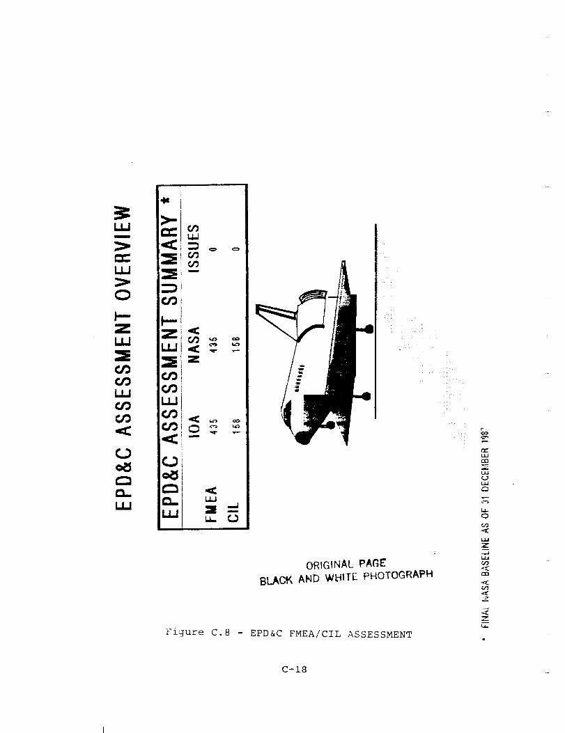
C.8 Electrical Power Distribution and Control
The IOA product for the Electrical Power Distribution and Control
analysis consisted of 1,671 failure mode analysis worksheets that
resulted in 468 PCIs being identified. Comparison was made to
the proposed NASA Post 51-L baseline (as of 31 December 1987),which consisted of 435 FMEAs and 158 CIL items. Differences
between the number of IOA worksheets and NASA FMEAs resulted from
different levels of analysis (e.g., grouping components into one
FMEA versus a worksheet for each component), failure modes not
being identified within the original analysis, and the fact that
two different schematic sets were used (NASA used Rockwell
International assembly drawings and IOA used the Rockwell
International integrated schematics). Figure C.8 presents a
comparison of the Post 51-L NASA baseline with the IOArecommended baseline.
The issues arose due to differences between the NASA and IOA
interpretation of the FMEA/CIL preparation instructions,
different definitions of screen detectability, and some ignorance
of flight procedures on the part of IOA. After comparison, there
were no discrepancies found that were not already identified by
NASA, and the remaining issues were the result of the differences
in the schematics used by NASA and IOA.
C.9 Landinq/Deceleration Subsystem
The IOA analysis of the Landing/Deceleration (LDG/DEC) hardware
initially generated 246 failure mode worksheets and identified
124 Potential Critical Items (PCIs) before starting the
C-17
u
c_
im-
us
7
ORIGINAL PAGE
BLACI_ AND W_ITE PHOTOGRAPH
Figure C.8 - EPD&C FMEA/CIL ASSESSMENT
_c
L/J
Um
O
&o
,lJ
Z
W
OO
Z
Z
t_
C-18
assessment process. In the analysis report, theLanding/Deceleration Subsystem was divided into six separatefunctional areas according to hardware and function. Difficultywas encountered in the hardware analysis due to the large amountsof proprietary hardware contained in the tires and wheels, and inmany of the mechanisms of the landing gear and the hydraulicssystems. The initial NASA document, STS 82-0013, consisted offive separate functional areas which included 118 FMEAs. Afterthe initial definition of the subsystem the 32 NWSFMEAs wereremoved and a separate group was initiated to prepare theanalysis for that subsystem. A decision was made to include theEPD&Cdata for the subsystem, and 122 electrical FMEASwere addedto the subsystem. Later, eight additional FMEASwere added tothe EPD&Cportion of the subsystem. In November 1986, 44hydraulics FMEAs were added to the subsystem. After the initialIOA analysis was completed in January 1987, a decision was madeto remove the pyrotechnic devices from the subsystem, whichremoved six FMEAs from the Nose Landing Gear and Main LandingGear subsystems. At the time of this report there are sixsubsystems that have been evaluated, including 267 NASA FMEAs and120 CIL items. There were 75 issues between the NASAdocumentation and the IOA data.
The IOA analysis did not include 14 of the NASA FMEAs due to thelack of data to support the evaluation, and many of the FMEAswere evaluated using documentation such as training manuals andcomponent procurement specification documents. The general lackof documentation and the proprietary nature of the data presentedmajor problems for the analysts.
The majority of the hardware issues were prepared on portions ofthe subsystem for which the NASA FMEAs covered a whole assemblywith a limited number of FMEAs. The IOA analysis concluded thata single NASA FMEAwas covering several i/i failures that werewithin the single FMEA. Several major components appeared to beoverlooked or considered to be a part of an assembly by the NASAassessment. The IOA assessment also uncovered several functionalFMEAs that were discussed with the NASA Subsystem Manager. Onlythe initial FMEAdata on the hardware subsystems was analyzed andthe assessment reflects only the analysis of that data.
The majority of the electrical (EPD&C) issues arose due tooperational discrepancies or evaluation differences on thecriticality of the function or hardware capability. This portionof the document was completely analyzed and the assessmentincludes the final resolution of the EPD&Cdata.
The interim IOA assessment report indicated 51Landing/Deceleration CIL issues. These issues represented abroad spectrum of differences between the IOA and NASA/Rockwellregarding documented hardware failure modes, criticalityassessments, and redundancy verification.
The IOA studied the revised Landing/Deceleration subsystemFMEA/CIL hardware documentation presented to the NSTS Level I/II
C-19
Review Board in April 1988. The IOA also examined thedocumentation presented to the CCB in January 1988 for hydraulicactuators and LDG/DEC EPD&Ccomponents. All this data wasfactored into a re-evaluation of the 51 CIL issues. As a result,all issues have been resolved (Figure C.9). The resolutionsrepresent either an agreement between the IOA and NASA/Rockwellor a concession by IOA to a more conservative analysis byNASA/Rockwell. There are no hardware failure modes considered tobe CIL items by the IOA but not by NASA/Rockwell.
Rationale for the resolution of each landing/deceleration issueis contained on the applicable assessment worksheets in thecompanion volume to this report, the CIL Issues ResolutionReport.
C.10 Purqe, Vent and Drain System
The IOA product for the Purge, Vent and Drain (PV&D) independent
analysis consisted of 62 failure mode worksheets that resulted in
16 PCIs being identified. A comparison was made of the IOA
product to the NASA FMEA/CIL dated 20 November 1987, whichconsisted of 42 FMEAs and 8 CIL items. The difference in the
number of IOA analysis worksheets and NASA FMEAs can be explained
by the different levels of analysis detail performed to identify
failure modes. The comparison determined if there were any
results found by the IOA that were not included in the NASA
FMEA/CIL.
The original assessment produced agreement on all but five
failure modes. Three failure modes for components were not
identified by the NASA FMEAs, one being a CIL item. Two failure
modes identified by IOA and NASA had differences in criticality,
resulting in two new CIL items. Subsequent research and
discussions with the NASA Subsystem Manager resulted in the
withdrawal of the three CIL issues. Figure C.10 presents a
comparison of the NASA PV&D FMEA/CIL baseline as presented to the
NSTS Level I/II Review Board on 8 April 1988, with the IOA
recommended baseline and any issues. Detailed discussion of IOA
issues and recommendations are provided in subsequent paragraphs.
The assessment between the IOA purge system worksheets and NASA
Post 51-L FMEA/CIL baseline produced one issue. IOA recommendsthe addition of a FMEA to the NASA baseline for the failure mode
"check valve leakage", as identified in IOA worksheet 9009. The
criticality for this failure mode is 3/3.
The original assessment between the IOA Window Cavity
Conditioning System (WCCS) worksheets and NASA Post 51-L FMEA/CILproduced three issues. IOA recommended the addition of a FMEA to
the NASA baseline for the failure mode "WCCS outer cavity tubing
clogging", as identified in IOA worksheet 9036. The criticality
for this failure mode was i/i and, therefore, would have required
NASA to generate a CIL. Further research and discussion with the
NASA Subsystem Manager resulted in this failure mode being
C-20

OR/GIN#,[. PAGE
8LACK AND WIflFE PHOTOGRAPN
Figure C.9 - LDG/DEC FMEA/CIL ASSESSMENT
L_U
Z ___
<D L*_
OU_Z _D
e9 Z
< _o
:)
'" 0¢.,,00
0
13... q._
z
C-21
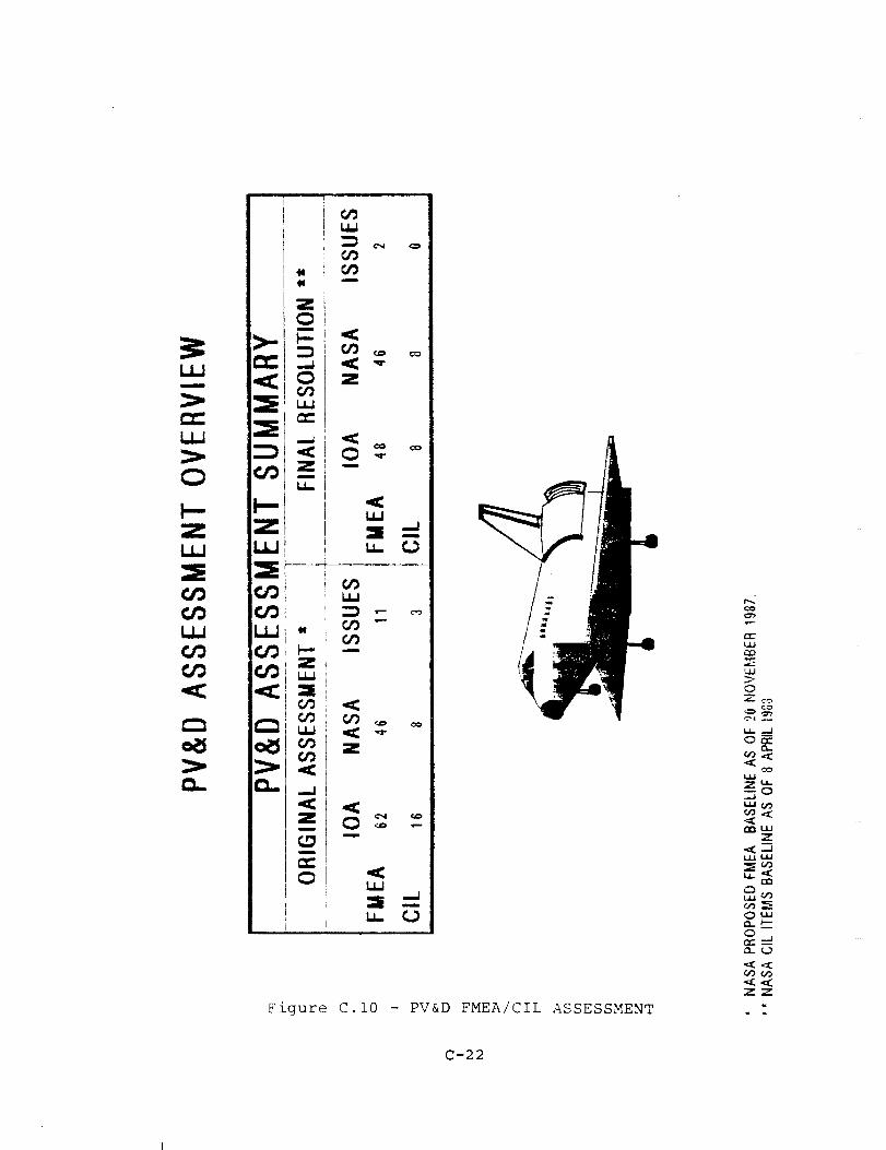
O
Z
]i
i
k_
Z
.... I
:> <o. _j
i i
f
k_
m
Z
Z
u-
Figure C.10 - PV&D FMEA/CIL ASSESSMENT
co
n-"
o
c_
WZ"
O'"
<)
ZZ
C-22

declared non-credible, and the issue was withdrawn. IOA agreed
to a i/I criticality for NASA Baseline FMEA/CIL 01-5-332404-5,
"WCCS desiccant filter outer cavity leakage". However, NASA
Baseline FMEA/CIL 01-5-332404-6 describes the same component,
same failure, and same results, but with different windows, as a
criticality 3/3. IOA recommended combining the two NASA FMEAs
with a criticality of i/I. IOA disagreed with NASA Baseline FMEA
01-5-332406-5, designated criticality 3/3. IOA worksheet 9037
for the same failure mode, "WCCS outer cavity tubing leakage",
identifies the criticality as i/I. NASA Baseline FMEA 01-5-
332403-1 identifies the same failure mode for the tubing, but for
a different set of windows, as a criticality i/I. Discussion
with the NASA Subsystem Manager revealed that NASA FMEAs 01-5-
332404-6 and 01-5-332406-5 are designated criticality 3/3 because
the forward and middle windows have a different venting scheme
and different delta pressure margins, which allow them to
experience these two failure modes without exceeding their delta
pressure margins.
The assessment between the External Tank/Orbiter (ET/ORB) Purge
Disconnect Network IOA worksheets and NASA Post 51-L FMEA/CIL
baseline produced one issue. IOA recommends the addition of aFMEA to the NASA baseline for the failure mode, "ET/ORB Purge
Disconnect external leakage", as identified in IOA worksheet
9060. The criticality for this failure mode is 3/3. IOA
recognizes this as a credible failure mode.
In conclusion, discussions with the NASA Subsystem Manager
resulted in the resolution of all IOA issues involving the PV&D
Subsystem CIL. Two issues remain with the PV&D non-CIL FMEAs.
C.ll PYrotechnics
The IOA analysis of the Pyrotechnics hardware initially generated
41 failure mode worksheets and identified 41 PCIs before starting
the assessment process. No additional failure mode analysis
worksheets were generated to facilitate comparison. These
analysis results were compared to the proposed NASA Post 51-Lbaseline of 37 FMEAs and 37 CIL items, which were generated using
the NSTS-22206 FMEA/CIL instructions. Upon completion of this
assessment, there were four IOA issues involving items which were
not part of the original NASA FMEA/CIL. Re-evaluation of items
using the NSTS Level I/If Review Board Presentation SSV88-71,
presented on 22 April 1988, resulted in the revising of the CILassessment items to 38 NASA items, 38 IOA items, and no issues
(Figure C.ll). Three new FMEA/CIL items were generated and two
deleted by NASA. The additional three items satisfied the four
original IOA issues, while the deletions were accepted by IOA
after additional system evaluation found the failure modes not to
be credible.
C-23

I I I II
PYROTECHNICS ASSESSMENT SUMMARY *
IOA NASA ISSU ES
FMEA 38 38 0
CIL 38 38 0
I II I
LANDING/DECELERATION
IOA NASA ISSUES
FMEA 9 9 0
CIL 9 9 0
I
I III I I II
I ORBITER/ET SEPARATIONtOA NASA ISSUES
I FMEA 12 12 0ClL 12 12 0
I
CREW STATION & EQUIPMENT
IOA NASA ISSUES
FMEA 6 6 0
CIL 6 6 0
FMEA
CIL
P/L RETNIDEPLOY
IOA I_ASA ISSUES6 6 0
6 6 0
NASA CIL ITEM BASEUNE
AS OF 22 APRIL 1988.
Fzgure
RENDEZVOUS RADAR ANTENNA
IOA NASA ISSUES
FMEA 5 5 0
CIL 5 5 0I
C.II - PYROTECHNICS FMEA/CIL
C-24
III
ASSESSMENT

C.12 Thermal Control System
C.12.1 Active Thermal Control System
The IOA analysis and assessment of the Active Thermal Control
System (ATCS) consisted of an evaluation of hardware in the
following subsystems: the Freon Coolant Loop (FCL), the Radiator
Flow Control Assembly (RFCA), the Flash Evaporator System (FES),
and the Ammonia Boiler System (ABS). The original assessment
produced agreement on all but 30 CIL issues and I01 non-CIL
issues. The re-evaluation process involved the 30 CIL issues.
All issues have been resolved.
Re-evalualtion by NASA of three of the items resulted in
criticalities which either agreed with IOA's completely or removed
it from the CIL list and from the issue list. A group of CIL
issues were resolved by accepting NASA's more conservative
groupings of failures or NASA's more conservative definition of
function and redundancy. Three CIL issues were resolved when the
failures were found in other NASA FMEA packages or as a subset of
existing ATCS failures.
During the original assessment, IOA had recommended highercriticalities for four of the CILs. After re-evaluation and
consideration of all redundancy paths, IOA returned to the
original criticalities and agreed with NASA. Also, after re-
evaluation, IOA agreed with the non-credibility of the failures
proposed by NASA.
Eleven of the CIL issues were discussed with the Subsystem
Manager. In seven cases, the discussion revealed sufficient
redundancy for IOA to agree with the lower criticalities. Three
of the issues (ATCS-3079, 3079A, 3067) produced agreement, in
theory, with the IOA criticalities. However, the Subsystem
Manager described current Level II guidelines which require the
assignment of dual criticalities. One issue resulted in a new
criticality being assigned after joint agreement by NASA and IOA.
In conclusion, all ATCS CIL issues have been resolved as shown in
Figure C.12a.
C.12.2 Life Support and Airlock Support System
The final Life Support System (LSS) and Airlock Support System
(ALSS) analysis and assessments were performed to establish a
criticality that was agreed to by both NASA and the IOA study.
These analyses were performed only on the items where issues
existed between the previous NASA and IOA criticalities.
Further, the analyses were limited to those issues which were CIL
related. All issues have been resolved, based on IOA internal
review and discussions with the NASA Subsystem Manager. A note
of interest is that across the system items which were previously
not strictly identified as issues were revisited. These were
related to previous assessments where a detailed assessment was
C-25

(;9
=I
_J
z
..J
i
m
i
OPJGINAL PAGE
BLACK AND WI._.TE PHOTOGRAPH
Figure C.12a - ATCS FMEA/CIL ASSESSMENT
_>-
K
C-26
not made due to the lack of NASA information at that time. Thefollowing paragraph gives insight to the resolution of the issuesthat previously existed.
The supply water subsystem had 34 CIL issues resolved. Twenty-four issues were withdrawn when the NASA criticality wasaccepted, six issues were changed to the IOA criticalities, andfour were revised to new criticalities.
The most significant issue was related to external leakage of H20from the H2 separators in the water line from the fuel cells tothe supply water tanks. Initial criticalities were based upontwo separate scenarios. The NASA scenario considered a loss ofFES situation that could result in a IR/2 criticality if asubsequent ABS or radiator failure occured. The IOA scenariotook the approach that water management protects against theusage of FES water until entry, but the loss of orbit FESoperation and drinking water results in a 2/2 criticality. Upon
reanalysis the IOA analyst took a third approach which was later
formalized by the NASA Subsystem Manager. The question to answer
considered what happened to the H20 as it went overboard throughthe vacuum vent line. Final determination was that an
uncontrollable buildup of ice would result, which could seriously
damage the vehicle upon entry. Thus a revised criticality of i/I
was agreed upon. Three other criticalities were revised to
mission critical within the galley supply water lines, based upon
leak isolation capabilities.
The six criticalities which were revised to match IOA were based
upon unisolatable supply water leaks which resulted in free water
in the cabin, thus resulting in mission termination. The 24
issues where IOA accepted the NASA criticality were based upon
further understanding of fuel cell H20 dead head conditions (7),
effects of H2 in the Extravehicler Mobility Unit (EMU) H20 (2),
ice build up conditions at the H20 servicing ports (6), effects
of supply tank outlet plumbing failures on FES operations (8),
and water dump redundancy considerations (i).
In the Waste Management Subsystem, 27 issues were resolved.
Seventeen were withdrawn when the IOA task accepted the NASA
criticality. Seven resulted in the NASA Subsystem Manager
agreeing with the IOA recommended criticality, and three were
resolved through further discussion which revised the
criticalities to a new position from that previously held by
either party.
In the case of the issues withdrawn in favor of the NASA
criticalities, seven were based upon the definition of redundancy
and the fact that the Fecal Collection Bag (FCB) and Urine
Collection Device (UCD) only provide for a one day extension,
rather than providing actual redundancy. The remaining i0 were
based upon the final agreement on the worst case scenario. The
worst case scenarios were related to the interpretation of leak
isolation redundancy, UCD redundancy considerations, usage of the
contingency cross-tie, and hazardous atmospheres created by
C-27

vacuum vent line blockage.
The seven IOA criticalities agreed to by NASA were associatedwith consistency within the waste water dump system. Two of therevised criticalities also were in this category. The remainingrevised criticality was related to the purpose of the vacuum lineheater and the fact that the assessment was initially madeagainst the wrong NASA FMEA.
Twenty issues were resolved related to the Smoke Detection andFire Suppression subsystem. Fifteen issues were resolved whenthe IOA task accepted the NASA criticalities and withdrew theissues. Five issues were resolved when further NASA analysislead to the criticalities matching the IOA analysis presented inthe assessment report for this subsystem (reference 56). Thebases for these resolutions are discussed in the followingparagraphs.
Justification for withdrawing the IOA issues were derived fromthe following considerations. The first justification was basedupon the determination of failure detectability (screens A & B)and the passing or failing of the screens. When this was anissue the higher criticality was accepted, since more visibilityis given to the item. Eight items, five of which were CIL items
and three that were CIL vs Non-CIL, were in this category. The
second justification was based upon analysis data where the IOA
criticality relied upon the usage of portable fire bottles to
suppress avionics bay fires prior to main engine ignition. Upon
further investigation, the concerns of the NASA Subsystem Manager
on the difficulty of reaching the ports were determined to have
merit. Five items were in this category.
Finally, two issues were withdrawn because the IOA failures
within components were determined to be non-credible. The dataused to determine this came from sources external to the NASA
Subsystem Manager.
Five issues were resolved based upon further analysis. These
analyses led to NASA criticalities that matched the IOA data
presented in the assessment report (reference 56).
In the Airlock Support System (ALSS) 53 items were reviewed.
This was one of the major subsystems where detailed NASA
data was not available when the original assessments were
performed. Except in one case, all ALSS issues were withdrawn.
The one case resulted in a revised criticality to provide
consistency with components in the same circuit. The withdrawn
issues were mostly based upon IOA accepting the philosophy that
the airlock must support contingency extravehicular activity
(20), and that EMU provisions are redundant (18). Other
justifications were based upon different interpretations of
remaining success paths, various erroneous assumptions on airlock
operations, and a more conservative approach taken by NASA.
Figure C.12b documents the final results of the IOA assessment.
C-28
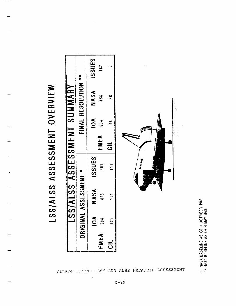
UJ
zU-
Z
09um
m
-W"
Z
cz_w
u_
U_
OOm
6/) _ _-
Z
I
U_
r Um O
Figure C.12b - LSS AND ALSS FMEA/CIL ASSESSMENT
o%
o_
&z_u_
OO
(/9 (F)
_-Z
ujI1,
U9_'3
<f,_X
_9(/)
m
-- C-29

C.13 Crew Equipment
The IOA analysis and assessment of crew equipment examined
hardware associated with Extravehicular Activity (EVA) equipment,
EVA tethers, EVA tools, Intravehicular Activity (IVA) tools, food
assemblies, and miscellaneous Orbiter hardware. The original
assessment process produced agreement on all but four CIL issues.
During the secondary assessment, all cases were re-examined and
withdrawn. The cases where NASA had been recommending a higher
criticality than that suggested by IOA were agreed with by
recognizing the validity of stricter definitions of function and
redundancy. The items where IOA had not originally identified a
corresponding NASA FMEA were re-examined and implicit matches
were identified. In conclusion, all CIL issues were withdrawn.
Issues still remain with 123 non-CIL failure modes. Figure C.13documents the final results.
C.14 Instrumentation
The IOA analysis of the Instrumentation hardware initiallygenerated 88 failure mode worksheets and identified 8 PCIs before
starting the assessment process (Fig. C.14). These analysis
results were compared to a NASA baseline which was frozen as of 1
January 1988, with 14 Post 51-L FMEAs included in a total of 96
FMEAs and 18 CIL items, which were generated using the referenced
FMEA/CIL instructions. Upon completion of the assessment, 82
of the 107 FMEAs were in agreement. Of the 25 that remained, 4
are 2/2 criticality and not currently on the NASA CIL list and 7
new FMEAs were generated which had no NASA match. The remaining
14 FMEAs are of a different criticality than the NASA
interpretation. None of these 14 FMEAs affect the CIL listing.
The four CIL items were for failures of the Operational
Instrumentation MDMs OF1, 2, and 3. The Instrumentation CCB
meeting of 2 March 1988 reflected that all MDMs were addressed by
the Data Processing System (DPS) CIL presentation of 14 December
1987. Upon subsequent contact, the DPS personnel referred the
IOA analysts to the fuel cell subsystem. Analysis by fuel cell
personnel revealed that the failures identified were not CIL
items. The IOA's initial concerns were with redundancy for the
fuel cell measurements that these MDMs provide. The fuel cell
analysis revealed that redundancy is provided.
C.15 Data Processing System
The IOA analysis of the Data Processing System (DPS) hardware
initially generated 85 failure mode worksheets and identified 2
PCIs before starting the assessment process. In order to
facilitate comparison, 37 additional failure mode analysis
worksheets were generated (See Fig. C.15). These analysis
results were compared to the proposed NASA Post 51-L baseline of
78 FMEAs and 25 CIL items, which was generated using the Rockwell
C-30
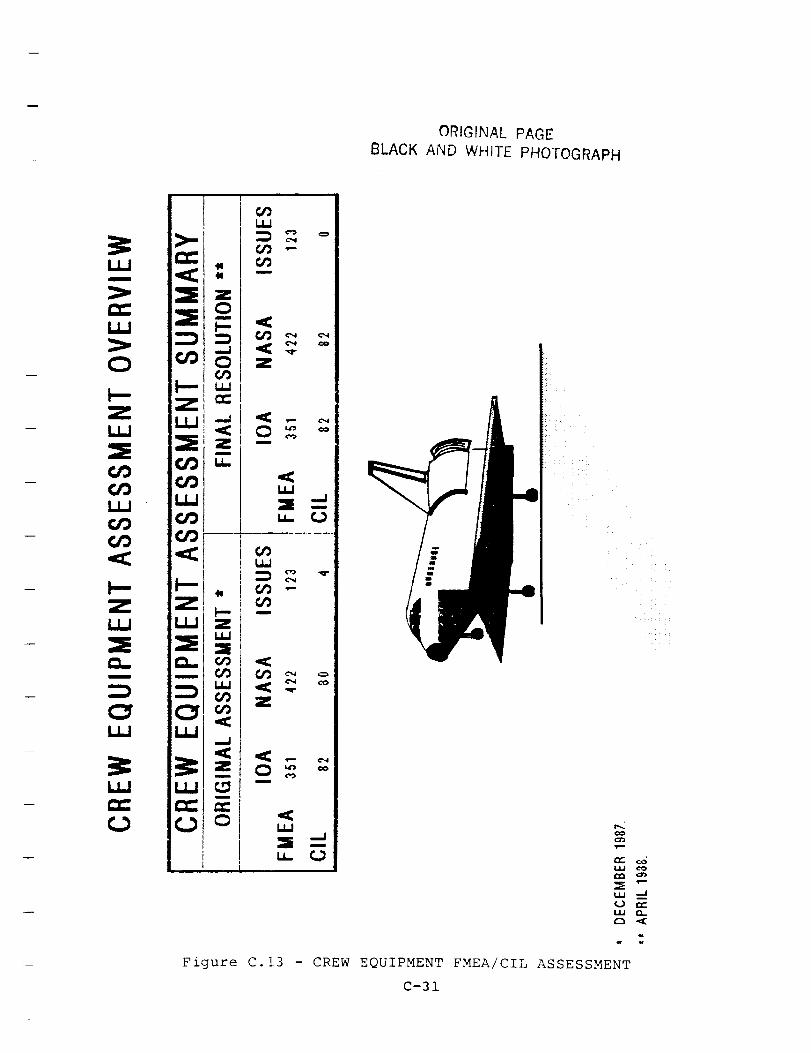
ORIGINAL PAGE
BLACK AND WHITE PHOTOGRAPH
i!!/
_>.
I.I,J
ILl
c_
ill
I-..Z111
m
I11
:=E z_i:_ o
i.,,.
IL
i
i._. _,11
u.jI =,,
u..Jl ...
LLI
G'Jinlnlll
=l,
n
,ICLLI
u,.. r,j
LLI
I
_,-, oZ
co
LI..I
_. --"iii ._.1
Figure C.13 - CREW EQUIPMENT FMEA/CIL ASSESSMENT
C-31
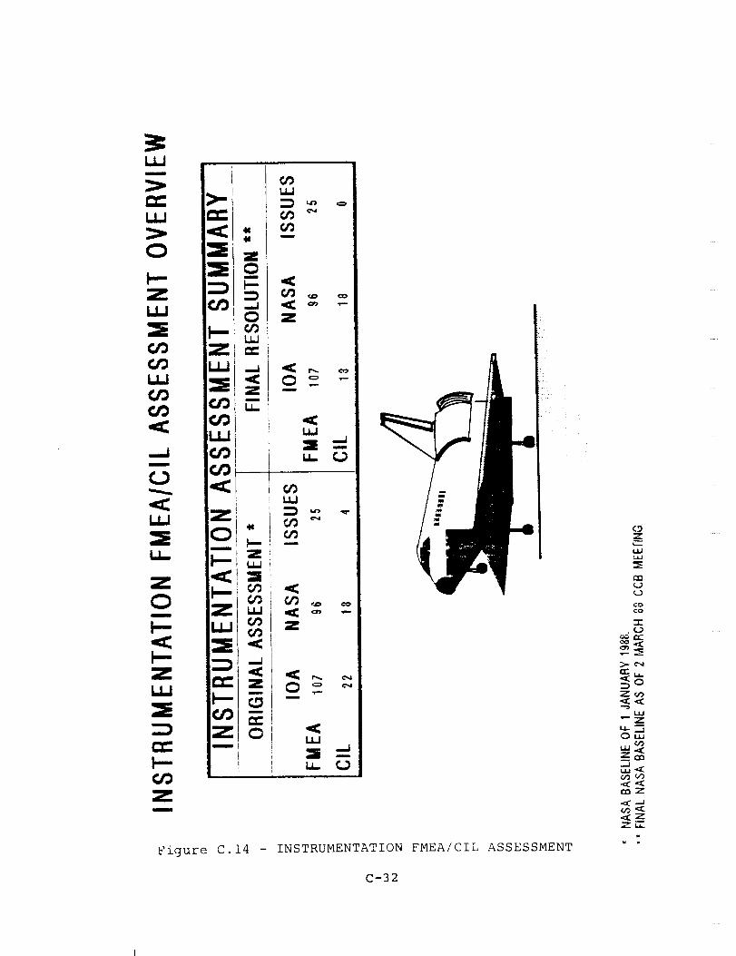
m
O
Z
..Jm
u_
Z
Om
Zm
>-
=E=E
'J3!
Z.J.J
=S
U_
Z
0m
.<
Z
Zm
: i
, [
Z0mmm
,,.,J0
L.W
Z
W.J
i
.,C
Z
m
u
u.. C_
_-. .-.Z_
=R<_
_,z.<
m
0 <U.J
Figure C.14 - INSTRUMENTATION FMEA/CIL ASSESSMENT
C-32
tA_
coco
.(_
"_o
z_
"-z
_m._.1
ec_Z
¢._,_

!
ZU_
Ill
-.Ji
U_
tu
I==z
I_
a.
t_
_=
u_
Figure C.15 - DPS FMEA/CIL ASSESSMENT
z
u_oo
0o
Z'"0
t,I..I _.., 1
oe.._
" z
._z7r?
C-33

00-2G FMEA/CIL instructions. Upon completion of the assessment,
60 of the 78 FMEAs were in agreement. Of the 18 that remained,
14 had minor discrepancies that did not affect criticality. Of
the remaining four, two issues were with FMEAs (05-5-B03-I-I and
05-5-B03-2-I) that had considered failure modes outside the DPS
subsystem, and caused inflated criticalities. These
criticalities placed both FMEAs on the CIL. The other two issues
were also with FMEAs (05-5-B01-I-I and 05-5-B02-I-I) that
considered failure modes outside the DPS subsystem. However,
when the correct failure mode is included, the current
criticalities will remain unchanged. In summary, all issues may
be attributed to differences between ground rules in Rockwell
100-2G and NSTS 22206 instructions.
The two remaining DPS CIL issues shown in the IOA Interim Report
(reference 70) concerned FMEAs 05-5-B03-I-I and 05-5-B03-2-I,
loss of output from FA and FF MDMs respectively. The IOA
considered these failures to be non-CIL items with 3/IR
criticality. In the November 1986 version of the proposed post
51-L baseline, both FMEAs were considered by NASA/Rockwell to be
2/IR, which categorized them as CIL items. NASA and Rockwell
conducted several reviews during 1987 and substantially revised
all CILs. FMEA 05-5-B03-2-I, "MDM FFI-4 loss of output", was
downgraded to 3/IR, which agrees with the IOA analysis.
NASA/Rockwell chose to retain the 2/IR criticality for FMEA 05-5-
B03-1-1. The criticality assessment difference for this FMEA is
withdrawn as an issue since the NASA/Rockwell value represents a
more conservative application of the NSTS 22206 instructions than
that imposed by the IOA.
C.16 Atmosphere Revitalization Pressure Control System
The original analysis and assessment of the Atmosphere
Revitalization Pressure Control System (ARPCS) yielded issues
with 124 of the NASA FMEAs and 48 of the NASA CILs. During the
second phase of the assessment process, the 48 CIL issues werere-examined and resolved.
Re-evaluation by NASA of the EPD&C failures resulted in revised
criticalities for four of the CIL issues. These revised
criticalities matched IOA's recommendations and the issues were
closed.
IOA's original analysis was completed before the decision to
remove the auxiliary 02 tank was made. The knowledge of this
design change led to a re-evaluation of IOA's assigned
criticalities and withdrawal of a second group of issues.
Two issues were withdrawn when they were found to be subsets of
existing NASA CILs. Additionally, another group of issues were
withdrawn when IOA accepted NASA's more conservative definition of
redundancy and credible failure modes.
Sixteen issues were discussed with the NASA Subsystem Manager,
C-34

John Whelan, on 23 May 1988. Four of these involved oxygen flowto the Launch/Entry Helmets. The issues were withdrawn when itwas learned that a "Y" connection is flown permitting twocrewmembers to utilize one connection. This permitted adowngrading of the criticality from i/i to 2/IR. Eight issuesinvolved the N2 system. NASA utilized a ground rule, accepted byboth the PRCBand the CCB, which placed cabin integrity as a
backup to the N2 systems. Accepting this philosophy permits a
criticality downgrade from 2/IR to 3/IR. IOA withdrew these
issues. The remaining issues were closed when the Subsystem
Manager gave IOA a clearer understanding of the system and
component design and operation.
In summary, all CIL issues have been resolved. Figure C.16
presents the final resolution of the ARPCS assessment.
C.17 _yd_au_ic/Water Sp_av Boiler
The IOA product for the Hydraulic/Water Spray Boiler (HYD/WSB)
analysis consisted of 447 failure mode worksheets that resulted
in 183 PCIs being identified. An initial comparison was made to
the NASA baseline (as of 19 November 1986) which consisted of 364
FMEAs and iii CIL items. The comparison determined if there were
any •results which had been found by the IOA that were not in the
NASA baseline. This comparison produced agreement on all but 68
FMEAs, which caused differences in 23 CIL items. A second
comparison was made to the NASA FMEA/CIL baseline as documented
in the NSTS Level I/II Review Board Presentation of 30 March
1988. This comparison, and further investigation, resulted in
the withdrawal of 18 of the CIL issues. The remaining five CIL
issues were discussed with the NASA Subsystem Manager on 26 April
1988. As a result of this meeting, four issues were withdrawn,
and one issue was accepted by the Subsystem Manager. No IOA
issues remain with respect to the Hydraulic/WSB CIL. Forty-five
discrepancies remain involving non-CIL items. Figure C.17
presents a comparison of the NASA baseline with the IOA
recommended baseline, and any issues.
Details of the resolution of all the CIL issues are provided in
the companion volume to this report, the CIL Issues Resolution
Report (reference 71).
C.18 Mechanical Actuation Subsystem
Hardware assigned to the Mechanical Actuation Subsystem (MAS)
includes mechanisms of nine Orbiter subsystems. They include the
air data probes, elevon seal panels, ET umbilicals, Ku-Band
deploy mechanism, payload bay doors, payload radiators, personnel
hatches, vent door mechanisms, and star tracker door mechanisms.
The IOA analysis of this hardware initially generated 685 failure
mode worksheets and identified 476 PCIs before starting the
assessment process. In order to facilitate comparison, 28
additional failure mode analysis worksheets were generated.
C-35
OR._4t'.J,;,I. P_.GE :.:_
OF P_:._ _JA L,rTY
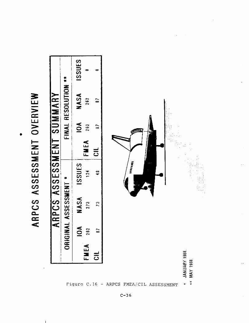
iii
O
Z ZLI.J
(_ C/3
a.. D..r_" rr'
m
.It
=m
.<
.<Zm
m
r.r.0
(,9
u
,<
k =. _-
Z
m
.<
== -.Ju_
co
_: >-<_ ._
Figure C.16 - ARPCS FMEA/CIL ASSESSMENT " :
C-36

c_LtJ.==gi
U.J _--_- Z
_: I!!=S
W
.-r-t
Q.
I-- ¢,_
_N'Z ""
U.I
i:l
W
..J
0
o.
Figure C.17 - HYDRAULICS/WATER SPRAY BOILER FMEA/CIL ASSESSMENT
C-37
zm.__ oo
__ <-)QC
GQD

These analysis results (Fig. C.18) were first compared to the
proposed NASA Post 51-L baseline of 510 FMEAs and 252 CIL items
as documented in the NSTS Level I/II Review Board Presentations
through 5 February 1988. The IOA assessment of this baseline
generated 310 issues.
During the subsequent re-evaluation review of these 310 issues,
two additional subsystem mechanisms were added. They are cabin
seals with 30 CILs and separation mechanisms with l0 CILs. This
makes the NASA Post 51-L Baseline 555 FMEAs and 292 CILs for the
MAS Subsystem. The 310 issues and the two additional mechanisms
involving the MAS CIL items were subjected to further IOAinternal review.
The IOA internal review revealed that the issues arose due to
differences between the NASA and IOA FMEA/CIL interpretation and
implementation of NSTS 22206. After comparison, there were no
discrepancies found that were not already identified by NASA; all
issues may be attributed to differences in ground rules.
Therefore all issues are withdrawn by IOA. Likewise, failures in
the Orbiter/ET mechanical separation mechanisms and cabin seals
were not initially analyzed by IOA due to differences between the
NASA/Rockwell and IOA interpretation and implementation of NSTS
22206. IOA has no issues with the NASA CILs presented to the
Review Board for these subsystems on 9 October 1987.
IOA also evaluated the NASA CIL package for the Manipulator
Positioning Mechanism (MPM) and Manipulator Retention Latch (MRL)
as presented to the NSTS Level I/II PRCB on 22 April 1988, andhas no issues with those CILs.
As a result of the IOA internal review, all issues were
withdrawn. Upon completion of the assessment, no IOA issues
remain with regard to the NASA MAS CIL.
C.19 Manned Maneuverinq Unit
The IOA analysis of the Manned Maneuvering Unit CMMU) hardware
initially generated 136 failure mode worksheets and identified 69
PCIs before starting the assessment process. In order to
facilitate comparison, 57 additional failure mode analysis
worksheets were generated. These analysis results were compared
to the proposed Martin Marietta Post 51-L baseline of 179 FMEAs
and ii0 CIL items. Upon completion of the assessment, 121 of the204 IOA failure modes remained as issues to be resolved. A
summary of the FMEA/CIL counts for IOA and NASA is provided in
Figure C.19, and some of the significant issues follow.
The Martin Marietta analysis format lacked a comprehensive
definition of the flight phases, screens, and the item(s) under
study. All the flight phases were not always analyzed for Prep,
Ops, and Post-Ops for each failure mode. The screens A and B
were not specifically designated per NSTS 22206. IOA had to
interpret their status based on very limited information
C-38
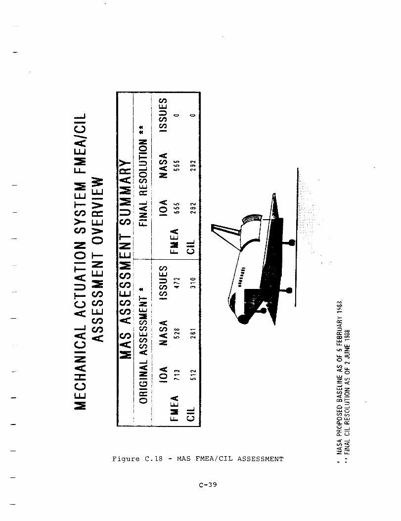
--J _9
Z
09,ll
EL
m
O
09
0909i
Z
I
_O
t_. T--
09 _
09m
09 _ .-
Z
m
W
Figure C.18 - MAS FMEA/CIL ASSESSMENT
_z
_O
oW
wZ
_,-.JuJOoooo0,,,0.. e_-
¢3_2 --
Z,,
C-39
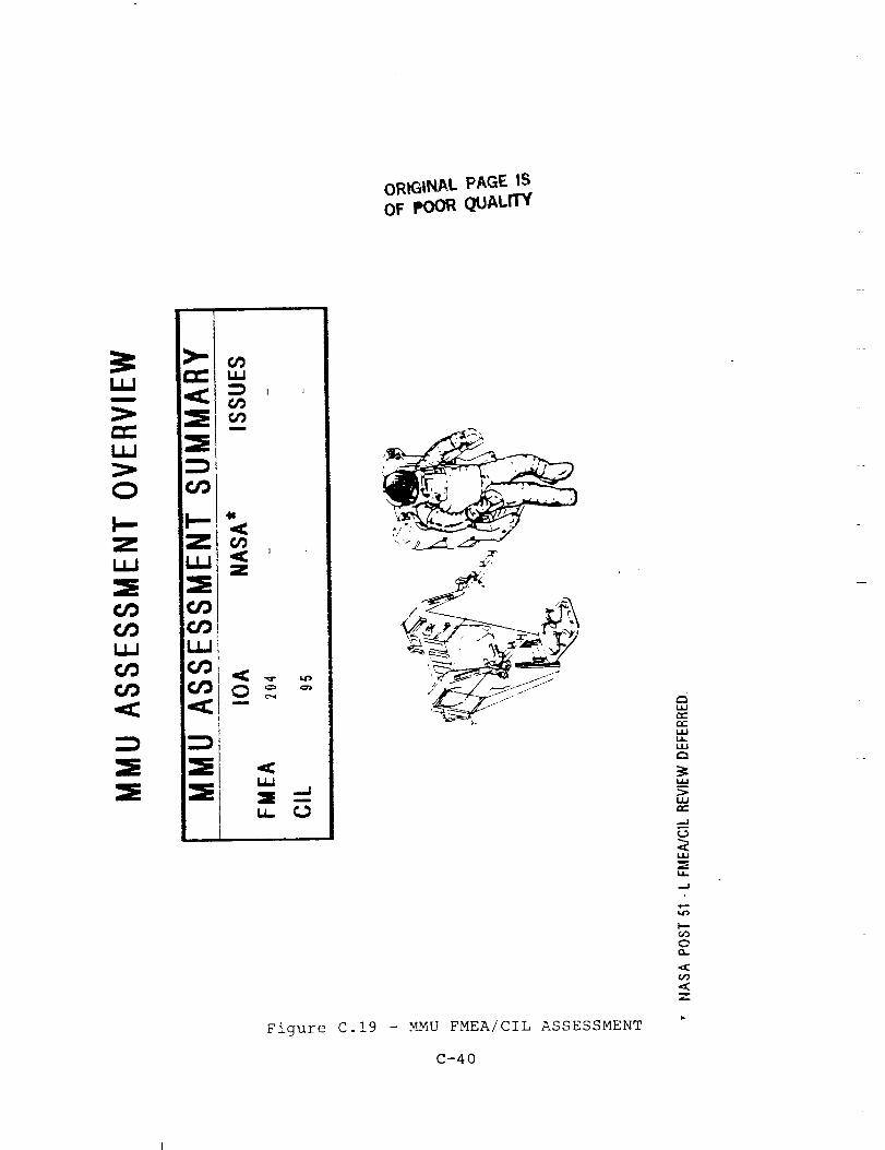
oRIGINAL PAGE tSOF POO_ QUALITY
I,.I.,I
el-,
i,,l,J
O
I--ZIll
I,,,I.I
¢,t3¢,/3
>-,-e'_,==:IE
t,/3
I--
¢,,/3(#'3,,=l:
t,/'lL_
z
I./,J
_= _u,.
Figure C.19 - MMU FMEA/CIL ASSESSMENT
C-40
,ll
W
..J
U.
__J
OO-
_9
Z
provided. Screen C was not addressed; and it was, therefore,
left blank throughout the assessment.
The Martin Marietta analysis did not address a specific hard-
ware item in some cases, but used an assembly instead. This made
it very difficult to investigate failure modes and effects of a
particular item and its impact on the overall system.
The MMU Prep and Post-Ops definitions were not too clear, and it
was consequently difficult to match their criticalities. IOA
considered every MMU activity to begin with Pre-Ops activities
and end with Post-Ops activities prior to the start of the next
MMU operations. The Martin Marietta definition seems to suggest
that the Prep activities start with the first MMU Pre-Ops and
stop after the last MMU Ops activity. The period after the last
planned MMU Ops will then be Post-Ops.
There were a number of issues related to the treatment of multi-
position switches. Martin Marietta used a more broad and general
failure mode approach, such as open or closed. IOA considered
and investigated the failure of single contact positions for open
and closed and assigned the worst case criticality. Multi-
position switches failing open or closed were, in general,considered to be unreasonable.
Electrical items, such as diodes, resistors, relays, etc.
associated with a Line Replaceable Unit circuit were not studied
by Martin Marietta. IOA provided analysis for these items to be
incorporated into the final FMEA/CIL study.
The MMU assessment was not part of the subsequent CIL issue
resolution effort, because of the NASA decision to defer
indefinitely the review of the MMU FMEA/CIL.
C.20 Nose Wheel Steerinq Subsystem
The IOA analysis of the Nose Wheel Steering (NWS) hardware
initially generated 78 failure mode worksheets and identified 42
Potential Critical Items (PCIs). As a result of the assessment
process, 15 NWS failure mode worksheets were deleted and an
additional 5 analysis worksheets were generated and added to the
assessment package. The assessment comparison also gave rise to
14 issues between the IOA NWS analysis and the corresponding NASA
FMEAs (Fig. C.20).
Of these issues, nine are the result of failure modes generated
by the IOA that did not have corresponding NASA FMEAs. Theremainder of the issues are the result of differences in the NWS
subsystem failure mode assigned hardware/functionalcriticalities.
The most significant Orbiter assessment issue was uncovered
during the NWS subsystem analysis. The failure mode was a
"stuck" autopilot pushbutton causing the worst case effect of
C-41

< I_
Z
C;9 "-
z
m
u_ O
Figure C.20 - NWS FMEA/CIL ASSESSMENT
¢o
0__
O0
L_.I L.I.I
C-42

ioss of crew/vehicle (criticality i/l). The Orbiter autopilot is
used for entry, and manually disengaged before landing. The
autopilot is engaged by "Roll/Yaw Auto" and "Pitch Auto"
pushbutton indicators (PBIs). If either "Auto" PBI fails closed,
the autopilot cannot be permanently disengaged. With the
autopilot remaining engaged, the Orbiter will attempt to
"autoland", which requires a Microwave Landing System (MLS) on
the ground. The MLS is not required for day landings, and hasnot been "available" for four of the last seven STS missions.
Without the MLS, use of the autoland alone will cause the Orbiter
to miss the runway. A single point failure with no redundancy
and which threatens loss of crew/vehicle is categorized by NSTS
22206 as a "criticality I" item. Rockwell is adding the failure
mode to the FMEA/CIL baseline and developing a software change to
bypass a failed "Auto" switch.
The IOA assessment of the existing CILs gave rise to nine issues.
Of these issues, eight were the result of IOA identifyingadditional Potential Critical Items. One PCI concerned the
generation of independent FMEA/CILS for like critical hardware as
recommended by NSTS 22206. A second PCI was the result of an IOA
recommended criticality upgrade. The remainder of the eight PCIs
concerned hardware or failure modes excluded by the NASA
analysis. IOA also recommended the deletion of one NASA CIL.
The NWS PRCB Presentation of the Hardware/EPD&C presented no
issues with the IOA Assessment. The nine CIL issues were with
the "stuck" PBI and the Hydraulic/Mechanical CIL's. These issues
were presented by IOA at the 21 December 1987 NWS CCB. The
Chairman directed the Subsystem Manager and Rockwell to workthese issues. The stuck PBI was addressed at the GNC PRCB of 8
April 1988. IOA agrees with NASA's criticality assignment of
this issue. Five of the remaining Hydraulic issues were resolved
with the NWS presentation of 15 April 1988. The remaining three
issues (i. filter fails to filter, 2. hose assembly leakage, 3.
check valve closed) were withdrawn by IOA. Number 1 was
withdrawn as a non-credible failure, and numbers 2 and 3 were
considered covered in other CILs.
C.21 Remote Manipulator System
The IOA analysis of the Remote Manipulator System (RMS) consisted
of an analysis of the RMS EPD&C and an analysis of the RMS
hardware. The analysis of the RMS hardware encompassed the end
effector, the RMS Displays and Controls, the Manipulator Control
Interface Unit (MCIU), the Arm Based Electronics (ABE), and the
mechanical arm. At the end of £he original assessment phase, 453FMEAs had been identified as well as 324 CILs. IOA and NASA
disagreed on the criticality of 69 of the CILs.
During the second phase of the assessment, these 69 issues were
re-examined by IOA. The issues involve the problem of
uncommanded motion of the arm in the vicinity of the Orbiter.
IOA originally recommended this failure type be assigned a i/i
C-43
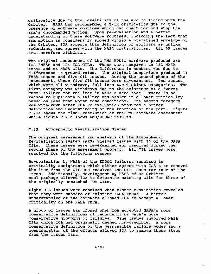
criticality due to the possibility of the arm colliding with the
Orbiter. NASA had recommended a 2/IR criticality due to the
presence of software routines which can check for and stop the
arm's uncommanded motion. Upon re-evaluation and a better
understanding of these software routines, including the fact that
arm motion is considerably slowed within a predefined envelope of
the Orbiter, IOA accepts this definition of software as unlike
redundancy and agrees with the NASA criticalities. All 69 issues
are therefore withdrawn.
The original assessment of the RMS EPD&C hardware produced 368
IOA FMEAs and 124 IOA CILs. These were compared to 132 NASAFMEAs and 66 NASA CILs. The difference in numbers was due to
differences in ground rules. The original comparison produced ii
FMEA issues and five CIL issues. During the second phase of the
assessment, these five CIL issues were re-examined. The issues,
which were all withdrawn, fell into two distinct categories. The
first category was withdrawn due to the existence of a "worstcase" failure for the item in NASA's data base. There is no
reason to duplicate a failure and assign it a lower criticality
based on less than worst case conditions. The second category
was withdrawn after IOA re-evaluation produced a better
definition and understanding of the function of the part. FigureC.21a shows the final resolution of the RMS hardware assessment
while figure C.21b shows RMS/EPD&C results.
C.22 Atmospheric Revitalization System
The original assessment and analysis of the Atmospheric
Revitalization System (ARS) yielded issues with 36 of the NASA
CILs. These issues were re-examined and resolved during the
second phase of the assessment project. All CIL issues were
resolved for the following reasons.
Re-evaluation by NASA of the EPD&C failures resulted in
criticality assignments which either agreed with IOA's or removedthe item from the CIL and resolved the CIL issue for four of the
items. Additionally, development by NASA of an Orbiter
seal package allowed IOA to determine matching CILs for three of
the originally unmatched IOA CILs.
Eight CIL issues were resolved when closer examination revealed
that they were subsets of existing NASA FMEAs. A better
understanding of the hardware allowed IOA to accept a lower
criticality on one NASA FMEA.
A group of issues was closed when IOA accepted NASA's more
conservative definitions of redundancy or NASA's more
conservative grouping of failures. Nine issues involved NASA
CILs which IOA had originally deemed non-credible. A more
conservative definition of the permissible failure modes and a
consideration of the effects allowed IOA to remove these items
from the issues list.
C-44
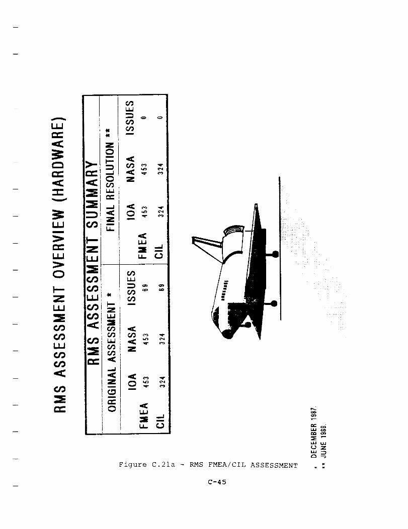
Figure C.21a - RMSFMEA/CIL ASSESSMENT
k/J
Z
w
_ C-45
u
U_
O
Z
t_
_O
O9
Z
U_
u_
O9t_
O9 --O9m
O9 o_ _.
Z
uJ
Figure C.21b - EPD&C/RMS FMEA/CIL ASSESSMENT
¢o>-
Z_C
C-46

Five issues were discussed with the Subsystem Manager. Four were
withdrawn after a better understanding of the system operations
and NASA's philosophical ground rules were obtained. One was
resolved when NASA agreed to issue a new FMEA with a mutually
agreed upon criticality.
In summary, all ARS CIL issues have been resolved.shows the final resolution of the ARS assessment.
Figure C.22
C.23 Extravehicular Mobility Unit
The IOA analysis of the Extravehicular Mobility Unit (EMU)
hardware initially generated 497 failure mode worksheets and
identified 390 Potential Critical Items (PCIs) before starting
the assessment process. In order to facilitate comparison,
additional failure mode analysis worksheets were generated.
These analysis results were compared to the proposed NASA Post
51-L baseline as of 1 January 1988 (Fig. C.23). The discrepancy
between the number of IOA and NASA FMEAs can be explained by the
different approach used by NASA and IOA to identify failure
modes, or simply by errors of omission. Fifty-three failure
modes were identified by the IOA analysis that were not covered
by the NASA FMEAs; 42 were considered issues due to CIL impacts.
With regard to the issues, the IOA identified a total of 153.
Ninety of these were concentrated in the Portable Life Support
System (PLSS) and the Display and Control Module (DCM). This was
not unexpected due to each subsystem's complexity and significant
use of redundancy. These features resulted in different levels
of analysis and in different determinations of redundancy by boththe IOA and the NASA. Another area of PLSS and DCM issues
resulted from differing usage of screen B detectability
requirements. The NASA established an interpretation that so
long as the crewmember could obtain safe haven upon detection the
screen would be passed; however, the IOA disagreed with the use
of an emergency system (the Secondary Oxygen Pack or SOP) to
support obtaining safe haven.
The largest remaining block of issues (40) were distributed
throughout the Hard Upper Torso (HUT), helmet, air assemblies,
gloves, and the Lower Torso Assembly. Although many of theseissues were similar in cause to those of the PLSS and the DCM
(namely different levels of analysis or different interpretation
of redundancy), a large group of these resulted from a common
failure mode - loss of pressure integrity. The NASA "qualified"
the failure mode as loss of pressure maintenance capability in
excess of SOP make-up capability. The IOA's concern was that it
automatically assumed loss of the SOP in assigning a i/i
criticality; the IOA preferred a 2/IR with a failure of screen B
and screen C to reflect the failure scenario.
The IOA participated in a series of meetings during June and July
of 1988 with representatives of the NASA Subsystem Manager,
Hamilton Standard, ILC-Dover, and Boeing Reliability to resolve
C-47
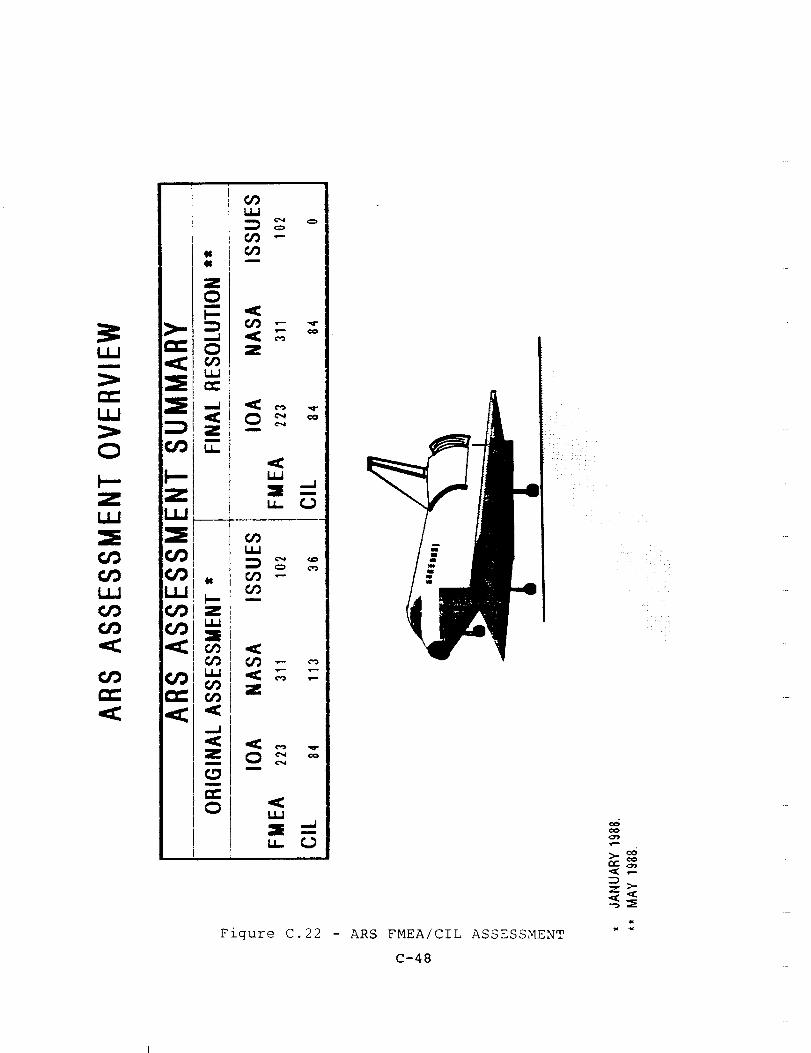
Zm
z _
Figure C.22 - ARS FMEA/CIL ASSESSMENT
C-48
z >-

O
Z
m
Z
I
k--Z
O
m
Z
u
Figure C.23 - EMU FMEA/CIL ASSESSMENT
Z
O
UJ
xG
Q_Q_
¢OCO
<O
h--"-<Q_
i.._ O0
_..UZ
U.I¢_
I..u_
OCLa.._,O,-r-
_ f.u
-- C-49

these issues. As a result of these meetings, all but 2 of the
153 issues were resolved. With regard to the 40 CIL issues, the
NASA accepted 24 IOA recommendations, and 14 IOA issues were
withdrawn.
The IOA accepted NASA's use of the SOP to support obtaining a
safe haven, allowing Screen B to be passed in those instances.
The NASA also established that loss of pressure integrity
failures could exceed SOP make-up capability, even with the SOP
functioning normally. Thus, the IOA accepted NASA's i/I
criticality for those loss of pressure integrity failure modes.
The remaining two CIL issues concerned failure modes IO0-FMI
(separation of the PLSS from the HUT) and 300-FM7 (separation of
the DCM from the HUT). The NASA considered these failure modes
credible for ascent and entry phases only, and gave them a
criticality of 2/2. The IOA asserted that the failure modes
could occur during EVA also, and recommended a higher criticality
(loss of crewmember would result if all redundancy were lost).
These two issues were presented to Clay McCullough/VP on 1
September 1988 for resolution. In that meeting, the NASA decided
to perform appropriate analyses to determine the credibility of
these failure modes due to EVA impact loads. The results of the
analyses will be used to determine the appropriate criticalityfor these failure modes. The IOA considers these two issues to
be accepted by NASA, by virtue of the actions being taken.
C.24 Power Reactant Storaqe and Distribution System
The IOA analysis of the Electric Power Generation/Power Reactant
Storage and Distribution (EPG/PRSD) hardware initially generated162 failure mode worksheets and identified 82 PCIs before
starting the assessment process. In order to facilitate
comparison, four additional failure mode analysis worksheets were
generated. These analysis results (Fig. C.24a) were first
compared to the proposed NASA Post 51-L baseline of 92 FMEAs and
58 CIL items, and then to the updated version of 66 FMEAs and 39
CIL items. They were finally compared to the baseline
configuration of 64 FMEAs and 39 CIL items for the two tank
baseline, and 67 FMEAs and 42 CIL items for the three and four
tank baselines as documented in the NSTS Level I/II Review Board
Presentation SSV88-I0, presented on 19 January 1988.
The nine issues involving the EPG/PRSD CIL items were subjected
to further IOA internal review. As a result of this internal
review, two issues were withdrawn. These were issues involving
CIL 04-1B-LV031-1 (MDAC ID 252, 264) and CIL M4-1BI-LV012-1 (MDAC
ID 278, 281). The first issue was withdrawn because the NASA
2/IR criticality is based on the assumption that loss of two fuel
cells during ascent constitutes loss of crew and vehicle. The
second issue was withdrawn because existence of a valve position
indicator driven by solenoid position cannot guarantee detection
of all valve internal leaks, thus screen B is failed.
C-50
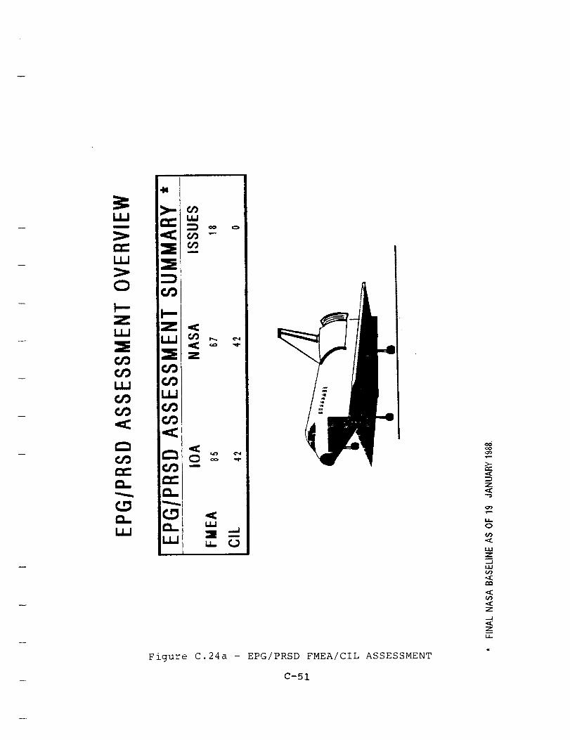
UJm
uU
O
Z
U_
O_
uJ
ud
_9m
Z
_z
Q-
__ Lu
Figure C.24a - EPG/PRSD FMEA/CIL ASSESSMENT
C-51
Z
i!
0
.aC
1.1.1
Z_J
LIJ(/)
.aE
Z
..J
zLL

The remaining issues were presented to the NASA Deputy Subsystem
Manager on 12 April 1988, and were withdrawn as a result of this
meeting.
Issues involving CILs M4-1BI-TK030-1 (MDAC ID 216, 217) and M4-
IBI-TK010-1 (MDAC ID 330, 331) were withdrawn because cryo tank
leakages are covered by CILs 04-1B-AOIFSO-I and 04-1B-A01FSH-I.
Issues involving CILs M4-1BI-RV031-1 (MDAC ID 231, 234), 04-1B-
LV-045-1 (MDAC ID 267), M4-1BI-RV011-1 (MDAC ID 307, 310), 04-1B-
LV015-1 (MDAC ID 275), and 04-1B-LV011-1 (MDAC ID 292, 295) werewithdrawn because the time available for crew action to close the
manifold valves after a worst case external leak is too short (7
seconds) for the CILs to credit the crew action as requiring an
additional failure (i.e., manifold valves fail open) before loss
of all fuel cells will occur. Thus, these CILs are criticality
2/IR rather than 3/IR. Upon completion of the assessment, and
after discussions with the Deputy Subsystem Manager, no IOA
issues remain with regard to the NASA EPG/PRSD CIL. Eighteen
discrepancies remain involving non-CIL FMEAs. Figure C.24a
presents the final resolution if the EPG/PRSD assessment.
The IOA analysis of the EPD&C/EPG hardware initially generated263 failure mode worksheets and identified 60 Potential Critical
Items (PCIs) before starting the assessment process. In order to
facilitate comparison, 42 additional failure mode analysis
worksheets were generated. These analysis results were compared
to the proposed NASA Post 51-L baseline of 211 FMEAs and 47 CIL
items, which was generated using the NSTS 22206 FMEA/CIL
instructions (Fig. C.24b). Upon completion of the assessment,
all of the 211 FMEAs were in agreement.
C.25 Main Propulsion System
The IOA MPS analysis generated 690 FMEA worksheets, 371 of
which were PCIs. Of the total, 438 FMEAs were generated for
mechanical components and 252 for electrical components (Fig.c.25).
General differences of opinion and interpretation between the IOA
MPS Group and the Rockwell/NASA MPS team resulted in different
criticality assignments. The Rockwell/NASA team, for example,
tended to have a broader view of an item's function than did IOA.
A related difficulty was the matter of redundancy. Again, the
Rockwell/ NASA team adopted a broader view of redundancy than did
IOA. Rockwell/NASA viewed sequential main engine failures as
loss of redundancy. IOA believes engines are not redundant to
each other because, while they perform identical functions, theydo not perform the same function.
Another area of differing opinions was the Rockwell/NASA practiceof introducing criticality i/i failures, such as line breaks or
leaks, as a second failure, thereby creating a 2/IR criticality
regardless of the first failure. IOA concludes that, in most
C-52

ORIGINAL PAGE
BLACK AND WI-{_t,E PHOTOG_APF!
I.LJ
ILl
>,.
Z
O
¢.f}
I.LI
Z
z
._J
ZI,,,1_
Figure C.24b - EPD&C/EPG FMEA/CIL ASSESSMENT
C-53
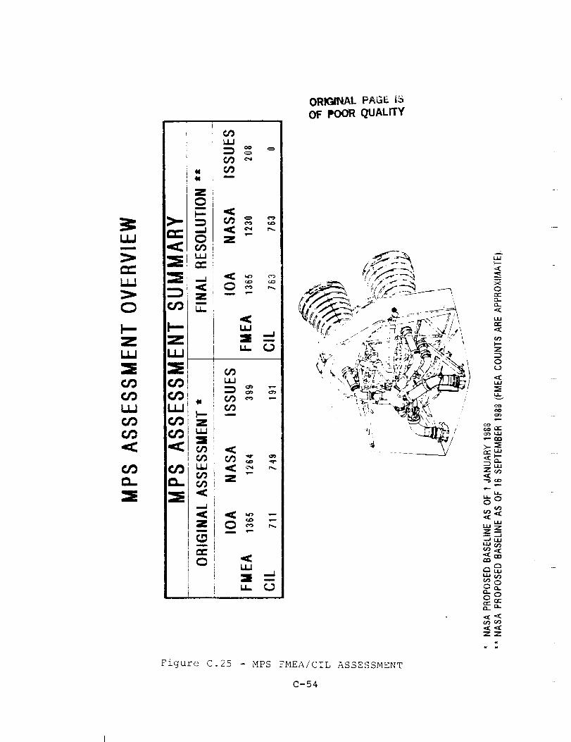
...--.-f-----.
,,=,
ZI,J.,I
¢JOCJDi11
_h
d,
__1
EL
ULI
m
,i,-.
Z
ELI
u__
GOI,J.I
u
LEt
t,,r;
.,Izr.s,,,,-
Z
ILl
U- t,,O
ORIGINAL PAGE iS
OF POOR QUALITY
t f I_x--_ _ ,. "_ " ..... , _.
°'--rf-Lu
_uJZ_
uJ.-_-- _.J
LU_
_oi:_ re-
Figure C.25 - MPS FMEAICIL ASSESSMENT
C-54

cases, this is not consistent with the NSTS 22206 methodology or
definitions.
The Rockwell/NASA approach tended to drive criticalities higher
than those determined by IOA. On the basis that a higher
criticality is more conservative and consistent with a worst case
approach, IOA was able to resolve many issues by accepting the
higher criticality of the Rockwell/NASA results.
The CIL issues were resolved by IOA internal review and by
meetings conducted in August and September of 1988 with
representatives of the Subsystem Manager. Final resolution ofthe 191 CIL issues resulted in the withdrawal of 148 issues and
acceptance by Rockwell/NASA of the IOA recommendation in 43
cases. Of these, 37 were CILs that Rockwell/NASA agreed to drop
because they were redundant to other analyses, 3 CILs were added,and 3 were modified.
Details of issue resolution can be found in the companion volume
to this report, the CIL Issues Resolution Report (reference 71).
C.26 Orbital Maneuverinq System
The IOA Orbital Maneuvering System (OMS) analysis generated 284
hardware and 667 EPD&C failure mode worksheets. Of these, 160
were hardware potential critical items (PCIs) and 216 were EPD&C
PCIs. A comparison was made of the IOA product to the NASA
FMEA/CIL baseline as of 23 December 1987 which consisted of i01
hardware FMEAs, 68 hardware CILs, 142 EPD&C FMEAs, and 49 EPD&C
CILs. In order to facilitate comparison, additional IOA analysis
worksheets were generated as required. IOA mapped 138 hardware
FMEAs, 93 hardware CILs and PCIs, 147 EPD&C FMEAs, and 47 EPD&CCILs and PCIs into the NASA FMEAs and CILs. The IOA and NASA
FMEA/CIL baselines were compared, and discussions were held with
the NASA Subsystem Managers in an effort to resolve the identified
issues. A majority of the initial hardware issues were resolved;
however, 47 hardware issues, 29 of which concerned CIL items, and
70 EPD&C issues, 31 of which concerned CIL items, remainedunresolved. The unresolved issues concerned NSTS 22206
interpretation differences, redundancy string definition
differences, failure modes identified by IOA which were not
addressed in the NASA FMEA/CIL baseline, and differences in
assigned criticalities, redundancy screens, and failure effects.All unresolved FMEA and CIL issues were documented in the IOA OMS
assessment report (reference 50).
The 60 OMS hardware and EPD&C CIL issues documented in the
assessment report were resolved during the IOA CIL issues
resolution effort. IOA met with J. Hooper (OMS Subsystem Manager
(SSM)) on 16 May 1988 to resolve the IOA CIL issues. The SSM
accepted two IOA issues. The first concerned a valve housing for
which there was no "structural failure" mode in the OMS FMEA/CIL.
The SSM agreed to add this valve housing to the prop line/valve
housing "structural failure" CIL (03-3-2101-1). The second
C-55
accepted issue concerned a two-pole toggle switch failure mode.NASA failed only one pole and considered the other pole to beredundant, whereas IOA considered an internal switch failurewhich caused both poles to fail simultaneously. The NASA failuremode required that the switch be placed in a certain positionbefore it could fail in that position, while the IOA failure modeallowed a short across any set of contacts with the switch in anyposition. The SSM accepted the IOA failure mode and rationaleand upgraded the criticality from a 3/IR to a 2/IR CIL. The SSM
stated that these issues would be incorporated into the OMS
FMEA/CIL during the next update activity. IOA withdrew the
remaining 58 CIL issues after in-house reviews and inputs from
the OMS hardware and OMS TVC SSMs, but maintains concerns and
recommendations on many of them. Refer to the individual IOA
assessment sheets in section C.17 of the companion volume to this
report (reference 71) for the withdrawal rationale for each ofthese 58 issues.
Figures C.26a and C.26b present the interim and final OMS FMEA/CIL
assessment results for the hardware and EPD&C, respectively. All
of the IOA OMS CIL issues have been resolved. However, IOA
maintains some concerns, which are presented in the following
paragraphs.
OMS FMEA 03-3-4002-2 (structural failure of the OMS engine inlet
filter) is classified as a 3/3, but could cause plugging of the
OMS engine injector and subsequent burn-through of an OMS engine.
This failure mode was classified as a 2/IR in the pre-51L OMS
FMEA/CIL baseline, but was downgraded by NASA and Boeingreliability to a 3/3 because it is also listed as a cause on 03-
3-4004-2 (restricted flow of the OMS engine injector, i/i). Thisaction was taken to reduce the number of OMS CIL items. As a
result, this failure mode with potentially catastrophic effects
is now classified as a 3/3 and will not receive the safety
attention it deserves. IOA contends that the criticality
assigned to this failure mode should reflect the fact that it
could ultimately result in loss of crew/vehicle. To have a
criticality assigned which does not reflect the worst-case
effects of a failure mode is misleading and could allow life and
vehicle-threatening failures to go unrecognized. The criticality
assigned to a failure mode on a FMEA should not be downgraded to
a 3/3 because that failure is also listed as a cause on a
separate FMEA. IOA could find no support for such a practice in
NSTS 22206, but withdrew the issue after Boeing reliability stood
by this downgrading practice. However, IOA strongly recommends
that the criticality on 03-3-4002-2 be reinstated to a 1 or IR
CIL, and that downgrading a failure mode to a 3/3 for this reasonbe discontinued.
Another IOA concern involves the 3/3 criticalities currentlyassigned to failure modes which allow the backflow of OMS
propellants from the propellant tanks into the helium
pressurization subsystem. IOA recommends that the "failed open"
and "internal leakage" failure modes for the quad check valve
assemblies and vapor isolation valves be classified as functional
C-56
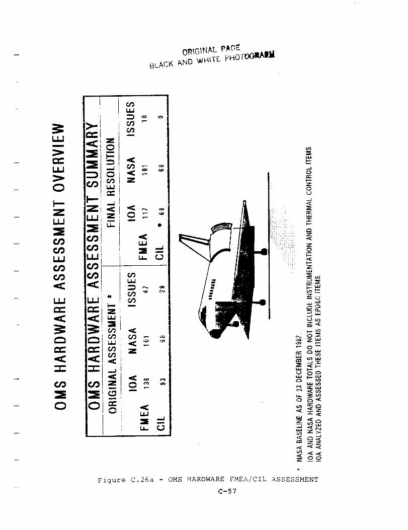
01RIG1NA L p/kG_
BLACK AND '_HITE.. P HOr_jij
U,,,I
,..I
0_-
o
..J
mm
n-
Z
0
Z_J
t..- _9
r.2 o ._
_ ¢,',_ LI.I
_ i.- u.,l
,.,, _z <
7££
Figure C.26a - OMS HARDWARE FMEA/CIL ASSESSMENT
C-57
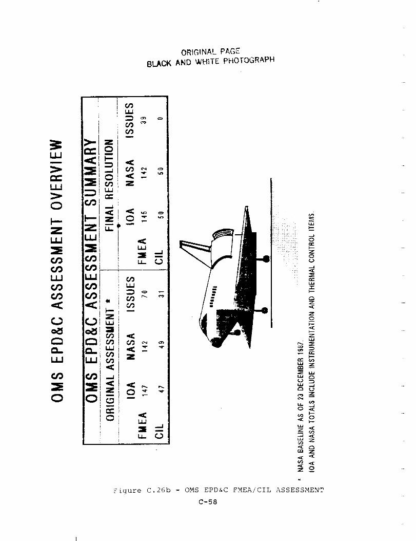
ORIGINAL PAGE
BLAC_ AND WHITE PHO[OGR4PH
O m
LWu
0
Figure C.26b - OMS EPD&C FMEA/CIL ASSESSMENT
C-58
criticality iRs. These failures would allow propellants to reach
the helium pressure regulator assemblies where contamination could
cause the assemblies to fail closed. Subsequent inability to
repressurize the OMS propellant tanks and use or deplete
propellants could result in loss of crew/vehicle. These failures
are currently also listed as causes on the regulator "fails
closed" FMEA (03-3-1004-2). The criticalities assigned to these
check valve and vapor isolation valve failure modes should reflect
the fact that they could ultimately result in loss of
crew/vehicle. IOA withdrew these issues after discussions with
the SSM, but maintains the recommendation.
On the current NASA OMS FMEA/CIL, one CIL sheet may include
several components and/or failure modes. The criticality and
screens assigned reflect only the worst case component failure
mode. IOA is concerned that this lumping of components and
failure modes on CILs reduces insight into the effects of
individual OMS subsystem component failures and may lessen the
attention given to critical failure modes. The components and
failure modes lumped together on one CIL could have different
criticality and screen assignments if they were separated onto
individual FMEAs and CILs, and better insight would be obtained.
For example, the bipropellant valve assembly FMEAs (03-3-4001)
include the engine control valve, pneumatic actuator, rack &
pinion assembly, bipropellant valves, and bipropellant valve
cavity pressure relief valve. IOA recommends that these
components be addressed on individual FMEAs and CILs and assigned
unique criticalities. This would provide better insight into the
effects of each of these component failures and would help ensure
that the critical failures receive the appropriate amount of
individual attention.
Some OMS subsystem failures do not exist as "failure modes" on
current FMEAs and CILs. Instead, they are listed only as causeson FMEAs and CILs for other failure modes. IOA is concerned that
a failure mode is not adequately addressed by only listing it as a
cause on a FMEA or CIL. For example, the "failed closed" and
"failed open" failure modes for the bipropellant valve cavity
pressure relief valve are addressed only as causes on 03-3-4001-6.All critical failures should be listed as failure modes on FMEAs
and CILs to help ensure that they receive the appropriate amountof attention.
Many of the IOA EPD&C CIL issues involved the definition of
redundancy. The NASA-applied definition of the redundancy string
allowed the selection of specific failures which were required to
cause known problems, e.g., failures required to cause continuous
power to a valve. IOA considers many redundancy strings to
include multiple failures, but withdrew related issues since the
NASA approach tended to be more conservative.
The final IOA concern involves electrical components within valves
(microswitches, diodes, etc.) which are not specifically addressed
on the current NASA OMS FMEA/CIL. IOA recommends that the EPD&C
components within a valve be addressed individually on FMEAs and
C-59
CILs to provide better insight into the effects of their failures,and to help ensure that critical failures receive the properamount of attention. Failures of valve EPD&Ccomponents are notvisible on the current valve hardware FMEAs.
The IOA CIL issues resolution effort initiated after the OMSinterim report was published involved only the resolution of CILissues. Therefore, the 57 IOA OMSFMEA (non-CIL) issuesdocumented in the interim report remain unresolved. IOA alsomaintains all recommendations and concerns put forth in theinterim report. The interim report may add to or supplementinformation presented in the final report.
Several changes have been made to the 23 December 1987 NASA OMSFMEA/CIL baseline since the assessment report was completed.However, IOA has found no changes which created new CIL issues.
The OMShardware results include the OMSTVC subsystem results.Five of the 60 OMSCIL issues were OMSTVC subsystem CIL issuesand were withdrawn by IOA.
The IOA analysis and assessment effort resulted in the followingchanges to the NASA OMSFMEA/CIL: the addition of a new i/i CIL
for blockage of the quad check valve assembly inlet filter (03-3-
1007-3), upgrades of flight criticalities on four FMEA/CILs,
upgrades to i/i abort criticalities on four FMEA/CILs, redundancy
screen changes on six FMEA/CILs, and the additions of eight
failure modes, eleven items, and eight causes to the NASA OMS
FMEA/CIL.
C.27 Reaction Control System
The IOA Reaction Control System (RCS) analysis generated 208
hardware and 2064 EPD&C failure mode worksheets. Of these, 141
were hardware potential critical items (PCIs) and 449 were EPD&C
PCIs. A comparison was made of the IOA product to the NASA
FMEA/CIL baseline as of 23 December 1987 which consisted of 99
hardware FMEAs, 62 hardware CILs, 524 EPD&C FMEAs, and 144 EPD&C
CILs. In order to facilitate comparison, additional IOA analysis
worksheets were generated as required. IOA mapped 166 hardware
FMEAs, 133 hardware CILs and PCIs, 597 EPD&C FMEAs, and 116 EPD&C
CILs and PCIs into the NASA FMEAs and CILs. After comparison of
the IOA and NASA FMEA/CIL baselines and discussions with the NASA
Subsystem Manager (SSM), 96 hardware issues, 83 of which concerned
CIL items, and 280 EPD&C issues, 158 of which concerned CIL items,
remained unresolved. The unresolved issues concerned NSTS 22206
interpretation differences, redundancy string definition
differences, failure modes identified by IOA which were not
addressed in the NASA FMEA/CIL baseline, and differences in
assigned criticalities, redundancy screens, and failure effects.
All unresolved FMEA and CIL issues were documented in the IOA RCS
assessment report (reference 51).
The 241 RCS hardware and EPD&C CIL issues documented in the
C-60

assessment report were resolved during the IOA CIL issues
resolution effort. IOA met with G. Grush (RCS SSM) on 19 May1988 and 2 June 1988 to resolve the IOA CIL issues. The SSM
accepted 37 IOA issues. Sixteen of the accepted issues concerned
the fact that the "internal leakage" and "restricted flow"
failure modes did not exist for several forward and aft RCS
components. The other accepted issues involved the addition of
the "structural failure", "rupture", and "external leakage"
failure modes for 21 RCS component housings which were notpreviously covered. The SSM stated that these issues would be
incorporated into the RCS FMEA/CIL during the next update
activity. IOA withdrew the remaining 204 CIL issues after in-
house reviews and inputs from the SSM, but maintains concerns and
recommendations on many of them. Refer to the individual IOA
assessment sheets in section C.18 of the companion volume to this
report (reference 71) for the withdrawal rationale for each ofthese 204 issues.
Figures C.27a and C.27b present the interim and final RCS FMEA/CIL
assessment results for the hardware and EPD&C, respectively. All
of the IOA RCS CIL issues have been resolved. However, IOA
maintains some concerns, which are presented in the followingparagraphs.
The current NASA RCS FMEA/CIL does not address the loss of forward
RCS propellant dumping capability. Many flights include a nominal
FRCS propellant dump after the deorbit burn in order to achieve an
improved X axis center-of-gravity (cg) condition for entry. Some
flights may be planned such that a post-deorbit FRCS propellant
dump is reg1_ired to move the X cg of the Orbiter back within the
allowable forward X cg limit for entry (1076.7 inches). Inability
to complete a required dump could, therefore, result in possible
loss of entry control. In assigning criticalities to FRCS
subsystem failures, IOA considered the possible effects of the
inability to complete a planned post-deorbit FRCS dump. The NASA
RCS FMEA/CIL review did not. As a result, IOA assigned 2/IR
criticalities to many FRCS subsystem failures which NASA currently
classifies as 3/IR. Failures which result in loss of propellant
tank repressurization capability, loss of propellant flow paths,
or loss of primary thrusters are the types of failures which
result in the inability to dump FRCS propellant.
The above IOA concern is underscored by GNC CIL # 05-I-FC6242-I
(loss of output from a FRCS reaction jet driver). This failure
-- results directly in the loss of a FRCS primary thruster. The NASA
GNC FMEA/CIL review also classified this failure as a 2/IR because
of the loss of FRCS dumping capability and possible loss of entry
_ control due to violation of the entry X cg limit. Yet, the RCS
FMEA which addresses loss of a FRCS primary thruster is classified
as a 3/IR because the FRCS dumping effects were not considered.
IOA urges that this inconsistency between criticalities assigned-- to failures with identical effects be corrected. The RCS
• criticalities assigned to FRCS subsystem failures which result in
loss of FRCS dumping capability should be upgraded to be
_ consistent with the IOA and NASA GNC approaches.
C-61

ORIGINAL PAGE
BLACK AND W1;-rlTE PHOTOGRAPH
LI.iiliiii
OI:ILl
O
I',--ZI.I.I
=E
ILII
_O
ILlt,-r-
¢-",1
¢J
Figure C.27a - RCS HARDWARE FMEA/CIL ASSESSMENT
C-62

_>I.A,.,_',,.,-\_.,D '7<i Iri.,. _ f< i L) I_XJR.",,P[_,
I.U-- m
_ Li.I
0
ZU.J
_ill¢0
tm
Figure C.27b - RCS EPD&C FMEA/CIL ASSESSMENT
C-63

IOA held a meeting on 2 June 1988 with the RCS SSM and personnel
from the Mission Operations Directorate, Rockwell, and Boeing
reliability to discuss the above IOA concern and related issues,
and to make propulsion and mass properties planning and
operations personnel aware of the IOA findings. Participants
concluded that the IOA concern was valid. During the meeting it
was confirmed that a nominal post-deorbit FRCS propellant dump
could be required on some missions. If the dump could not be
completed as required due to a subsystem failure(s), the forward
X cg entry limit would be violated resulting in possible loss of
crew/vehicle. There is currently no flight rule which prohibits
dependence on a nominal post-deorbit FRCS propellant dump in
order to meet the forward X cg limit for entry. For these
reasons, IOA contends that the inability to complete a planned
post-deorbit FRCS dump should be considered in NASA RCS FMEA/CIL
criticality assignments, and recommends upgrades on many FRCS
subsystem failures. IOA withdrew the issues related to this
concern (see applicable assessment sheets), but maintains theconcern and the above recommendations.
To summarize this concern, a major use of the FRCS subsystem is
management of Orbiter mass properties through propellant dumping.
This function may be critical and should not be neglected in
FMEA/CIL criticality assignments.
Another IOA concern involves the 3/3 criticalities currently
assigned to failure modes which allow the backflow of RCS
propellant from the propellant tank into the helium pressurization
subsystem. IOA recommends that the "failed open" and "internal
leakage" failure modes for forward and aft quad check valve
assemblies be classified as functional criticality iRs. These
failures would allow propellant to reach the helium pressure
regulator assemblies where contamination could cause the
assemblies to fail closed. Subsequent inability to repressurize
the RCS propellant tank and use or deplete propellant could result
in loss of crew/vehicle. These failures are currently also listed
as causes on the forward and aft regulator "fails closed" FMEAs
(03-2F-I01030-2 and 03-2A-201030-2). The criticalities assignedto these check valve failure modes should reflect the fact that
they could ultimately result in loss of crew/vehicle. IOA
withdrew these issues after discussions with the SSM, but
maintains the recommendation.
On the current NASA RCS FMEA/CIL, one CIL sheet may include
several components and/or failure modes. The criticality and
screens assigned reflect only the worst case component failure
mode. IOA is concerned that this lumping of components and
failure modes on CILs reduces insight into the effects of
individual RCS subsystem component failures and may lessen the
attention given to critical failure modes. The components and
failure modes lumped together on one CIL could have different
criticality and screen assignments if they were separated onto
individual FMEAs and CILs, and better insight would be obtained.
For example, the vernier thruster assembly FMEAs (03-2F-131310 and
03-2A-231310) include the inlet valves, injector, thrust chamber,
C-64

nozzle extension, heater, insulation, pressure transducer, andtemperature transducer. IOA recommends that these components beaddressed on individual FMEAs and CILs and assigned unique
criticalities. This would provide better insight into the effects
of each of these component failures and would help ensure that the
critical failures receive the appropriate amount of individual
attention.
Some RCS subsystem failures do not exist as "failure modes" on
current FMEAs and CILs. Instead, they are listed only as causes
on FMEAs and CILs for other failure modes. IOA is concerned that
a failure mode is not adequately addressed by only listing it as a
cause on a FMEA or CIL. All critical failures should be listed as
failure modes on FMEAs and CILs to help ensure that they receive
the appropriate amount of attention.
Many of the IOA EPD&C CIL issues involved the definition of
redundancy. The NASA-applied definition of the redundancy string
allowed the selection of specific failures which were required to
cause known problems, e.g., failures required to cause continuous
power to a valve. IOA considers many NASA redundancy strings to
include multiple failures, but withdrew related issues since the
NASA approach tended to be more conservative.
The final IOA concern involves electrical components within valves
(microswitches, diodes, etc.) which are not specifically addressed
on the current NASA RCS FMEA/CIL. IOA recommends that the EPD&C
components within a valve be addressed individually on FMEAs and
CILs to provide better insight into the effects of their failures,
and to help ensure that critical failuresreceive the proper
amount of attention. Failures of valve EPD&C components are not
visible on the current valve hardware FMEAs.
The IOA CIL issues resolution effort initiated after the RCS
interim report was published involved only the resolution of CIL
issues. Therefore, the 135 IOA RCS FMEA (non-CIL) issues
documented in the interim report remain unresolved. IOA also
maintains all recommendations and concerns put forth in the
interim report. The interim report may add to or supplement
information presented in the final report.
Several changes have been made to the 23 December 1987 NASA RCS
FMEA/CIL baseline since the assessment report was completed.
However, IOA has found no changes which created new CIL issues.
C.28 Communication and Trackinq
The initial IOA and NASA FMEA/CIL comparison analysis of the
Communication and Tracking (C&T) hardware and functions resulted
in 294 CIL issues. These issues were subsequently resolved in
several ways:
O Through discussions and agreements with NASA Subsystem
Managers of the C&T subsystem component elements.
C-65

00
00
0
0
0
NASA generated new FMEAs.Discovery of additional NASA FMEA/CILs not analyzed inthe initial assessment.NASA changed criticality designations.NASA agreed to generate new FMEAs to address IOAidentified failure modes.IOA withdrew failures which were considerednon-credible.IOA accepted the more conservative NASA CIL criticality
designations when IOA and NASA CILs were at variance.
IOA accepted NASA use of unlike redundancies not
previously considered by IOA.
Rationale for resolution of each CIL issue appears under the
"remarks" section on the applicable assessment work sheets
contained in the companion volume to this report, the CIL Issues
Resolution Report. Figure C.28 provides a numerical overview of
the C&T FMEA/CIL assessment.
C-66

Z
Z
Figure C.28 - COMM & TRACKING
C-67
FMEA/CIL ASSESSMENT
i==-
°>-
Z _
,_>.-
"0Q.
_9
W
UU(;9
Zv)&ZJ m
_Z
-,<
o u-7
t.,_ o
z _U.I _..
_z
L.I,4 (_
¢,,,e_
I,,--
z_z
O0
Zz_o
_..- I..---


APPENDIX D
Comparison of IOA Subsystems To Rockwell CIL Packages
A comparison of Orbiter subsystems assessed by IOA and
corresponding Rockwell CIL packages is presented in Table D-I.
IOA assessed several subsystems which are not part of the
Rockwell Orbiter CIL packages. Likewise, several of the Rockwell
CIL packages were outside the scope of the IOA analysis. This
category included mission-specific equipment, and emergency
egress equipment added to the Orbiter pursuant to the
recommendations of the Presidential Commission.
D-I

ORIC_.-:-:-:-:-:-:-:-_LPAGE IS
OF POOR (_'dALITY
TABLE D-1IOA TO ROCKWELL CIL PACKAGE COMPARISON
Fuel Ceil Powerptant (FCP)
SUBSYSTEMRockwell
CI L PackageiD
55,56
Hydraulic Actuators (HA) 14, 15
Displays and Control (D&C) 179,80
Guidance, Navigation & Controt (GN&C) 61,62
Orbiter Experiments (OEX) N/A
Auxiliary Power Unit (APU) 59,60
Backup Fright System (BFS) / DPS 83,84
Electrical Power, Distribution & Control (EPD&C) 85
Landing & Deceleration (L&D) 5,6,7,8.12,13
Purge, Vent and Drain (PV&D) 2
Pyrotechnics (PY RO) 31,40,108-112
Active Thermal Control System (ATCS) and Life Support System (LSS) 91-96,99-101
Crew Equipment (CE) 102,103
Instrumentation (INST) 81,82
Data Processing System (DPS) - Included in BFS
Atmospheric Revitalization Pressure Control System (ARPCS) 89,90
Hydraulics & Water Spray Boiler (HYD & WSB) 41,42,97,98
Mechanical Actuation System (MAS) 1,3,4,16-30, 33, 34
Manned Maneuvering Unit (MMU) N/A
Nose Wheel Steer= ng (NWS) 9-11
Remote Manipulator System (RMS) 37, 38, 39
Atmospheric Revitalization System (ARS) 186-88
Extravehicular Mobility Unit (EMU) N/A
Power Reactant Supply & Distribution System (PRS&D) 57,58,105,106
Main Propulsion System (MPS) 43-48
Orbital Maneuvering System (OMS) 51-54
Reaction Control System (RCS) 49,50
63-78Comm. and Tracki ng (C&T)
32, 35, 36, 104, 107,113-Not in IOA Scope 115
D-2