incremental describing function analysis of subharmonic oscillations in control systems with...
TRANSCRIPT

IEEE TRANSACTIONS ON INDUSTRIAL ELECTRONICS AND CONTROL INSTRUMENTATION, VOL. IECI-20, NO. 4, NOVEMBER 1973 229
tional circuits, which will make this mode of operation pos- REFERENCESsible. This should considerably broaden the range of experi- [1] Kimbark, E. W., "Power System Stability, Vol. III-Synchronousments, which can be carried out with the aid of the device. Machines," John Wiley and Sons, New York, 1956.
[2] Kalsi, S. S., D. D. Stephen and B. Adkins, "Calculation ofACKNOWLEDGMENT System-Fault Currents Due to Induction Motors," Proc. IEE,
Vol. 118, No. 1, 1971, pp. 201-215.The authors appreciate very much the contribution of Mr. [3] Sonnemann, W. K., C. L. Wagner and G. D. Rockefeller,
B. Smitlh, research technician, who built the equipment and "Magnetizing Inrush Phenomena in Transformer Banks," AIEETrans., Part III--Power Apparatus and Systems, Vol. 77, 1958,
did most of the detailed circuit development. pp. 884-892.
Incremental Describing Function Analysisof Subharmonic Oscillations in Control
Systems with Thyristor ConvertersGOPAL DE AND ASHISH K. MANDAL
Abstract-Often subharmonic oscillations of firing angle of ei Input signal to the nonlinearity.thyristor converters with large magnitude in negative feedback eO Output of the nonlinearity or the rectifier converter.control systems are a kind of jump phenomena. For their in- E Amplitude of supply voltage of the rectifier.vestigation rectifiers may be modeled by an asymmetrical satu- E, Amplitude of rectifier firing synchronizing voltage.ration type nonlinearity in series with a linear block whose Erl Ratio of the fundamental component of ripple to averagefactors depend upon the number of pulses of the rectifier and output voltage of rectifier converter with zero delay inthe order of subharmonic in question. Application of the in- firing.cremental describing function technique results in a set of k Preamplifier gain.curves, which is useful for the determination of the critical kb DC gain of the rectifier under balanced operating con-gain of the system and its design. Results of digital computer dition.simulated systems are in good agreement with the predicted m Number of pulses of the rectifier converter.values n Order of subharmnonic oscillation.
N Describing function of a nonlinearity.N' Derivative of N with respect to A.
NOMENCLATURE Ni Incremental describing function of a nonlinearity.A Amplitude of sinusoidal component of input to the non- Ne Envelope of incremental describing function.
linearity. p3 Real pole position of a 3rd order transfer function.B Bias or dc component of input to the nonlinearity. T 2ir/mco0, duration of each pulse of rectifier under bal-
anced operating condition.
Manuscript received February 28, 1973. This work was carried out as aT1 Real part of complex pole position of a 3rd order system.a part of a Sponsored Research Project on "Static Leonard Drive,' by Co1 Imaginary part of complex pole position of a 3rd orderM/x Jyoti Ltd., Baroda. sseC. De is at the Indian Institute of Technology, Bombay, India. sYstmA. K. Mandal is with Larsen & Toubro Ltd., Bombay, India. COO Frequency of rectifier supply voltage.

230 IEEE TRANSACTIONS ON INDUSTRIAL ELECTRONICS AND CONTROL INSTRUMENTATION, NOVEMBER 1973
INTRODUCTION E Cos(")t-_/mUse of thyristor converters with feedback control is quite
common nowadays in industrial drives and as a controlled dc m-Phasesource. High gain (power) and fast response are major attrac- supplytive features of a thyristor converter when regarded as an am-plifier. But as a control system component it has a number of ---->_ '- +discomforting traits too. The most obvious among them is eothat its output can be influenced by its input signal at discreteinstants only. These disquieting features do not permit thetreatment of a thyristor converter as a simple static device in Fig. 1. General m-phase rectifier converter.the analysis of control systems in which it is imbedded.For the purpose of analyzing stability of feedback control
systems, a thyristor converter has been variously replaced by a Epure gain element in series with a transportation lag [1], adiode [2], or a sampler along with a zero-order-hold (ZOH) 1 - - --[3]. In these works, the critical condition for runaway typeinstability has been investigated, the gain above which the sig-nals of the control loop will grow without bound for a bounded 1 _ ____ vcinput. However, it is the ripple-type instability [4], that is ex- X Espected to be met beyond the stable operating condition. In astable condition all the thyristors of a polyphase converter arefired with the same delay angle. If the delay angles are different -lfrom each other by certain magnitudes in a certain sequenceand the pattern is repeated at a definite frequency, the pheno- Fig. 2. Input-output characteristic of rectifier under balanced operatingmenon is described as a ripple-type instability. As each pattern condition.is to consist of two or more pulses, it may also be called "sub-harmonic oscillation." In [4] impulse analysis technique anddescribing function technique have been employed to deter- In thyristor converters using inverse cosine firing law themine the critical gain for oscillations of small and large magni- input to the firing circuit of each phase consists of the controltude delays, respectively. system actuating signal vC and a sinusoidal reference voltageRipple instability or subharmonic oscillation of firing angles of constant amplitude Es and suitably phased with the corre-
of thyristors in a converter can set on either gradually or sponding supply voltage. Gate firing signal is generated andabruptly. In the former case the magnitude of oscillation transmitted to the thyristor when this total input passes throughincreases gradually from an infinitesimally small value with the zero value towards positive.increase in gain, while in the latter oscillation of large magni- For a dc actuating signal the delay in the firing (as com-tude is inducted above the critical gain. It has been shown [5] pared to the natural angle of commutation) is constant and thethat only second order subharmonic oscillations can be gradual same for all the phases. This is described as the balancedphenomena and can be analyzed adequately by impulse analy- operation of the converter during which the ratio of meansis technique. On the other hand, higher order subharmonic output voltage and the dc actuating voltage is given byoscillations are so far known to be abrupt phenomena. mE . 7r
kb -sin-(1Feedback control systems containing certain type of non- 7rEs mlinearities are known to swing into sudden oscillation of a largeamplitude beyond critical conditions and incremental describ-
mgfunction (lDF) technique is a powerful tool for the analysis kb is independent of vc, and so under balanced operatingingr
Icondition the converter may be regarded as a linear amplifier,of such jump phenomena [6, 7].which is the major point of attraction of the inverse cosineThe present work proposes a new model for thyristor con-
verter and employs an IDF technique for the determination of mfiring law. For balanced operation the input-output relationcritical loop gain for higher order subharmonic oscillations.Results of the analysis have been compared with experimental spond to a = 0 and a = 1800. However, during oscillations or
investigation of digltal computer simulated systems. transient conditions, the operation of thyristor converters isnot balanced.
First of all, a rectifier converter is a discontinuously con-REALiTIESOFTHYRISTOR CONVERTERtrolled element. At the instants of firing, i.e., when uv, iS equal
A thyristor converter may be represented by the general to the instantaneous synchronizing voltage, a particular phasern-phase arrangement, as shown in Fig. 1. The effect of source of the supply voltage is switched on to the load as the outputimpedance and the small voltage drop across thyristors will be of the amplifier. Till the next firing instant the output voltageneglected. Of the many possibilities we shall consider here depends upon the waveform of the supply voltage and is inde-only inverse cosine firing law. pendent of what value vc, may assume inbetween. Thus the

DE AND MANDAL: INCREMENTAL DESCRIBING FUNCTION ANALYSIS 231
IRectifier 'L ZL eo
L_ Eb | (a)I -.+--'°I---;
Fig. 3. Typical rectifier load circuit. o T 2T 3T 4T
output is controlled by the input voltage VC at discrete intervals eOob)only. But a rectifier converter behaves neither as a pure ampli- (b)
tude-controlled nor as a pulsewidth modulated discrete-data I 2T 3T 4 telement. Under balanced condition, a given rectifier has a fixedelement Underbalanced condition, a.givenrectifnd Fig. 4. Rectifier output waveform (a) and sampler and zero-order-holdsampling rate of mco0/21T per second. But in dynamic condi- output (b).tions or in the presence of any waveform other than a dc onepulsewidths become different and unequal to each other.Thus, in the discrete-control element, thlat a rectifiler converter appearance is appealing to reason, it is justifiable in substancerepreseints thediscrecontrolnstants,in ealaretifirconoveq only by the degree of ease and accuracy with which it can ex-represents, the control instants, in general, are not equallyspaced apart and depend upon the input voltage waveform. plain and foresee the reality.Further, between the two control instants the output voltage The discrete nature of control with the output waveform ofis not constant; it is a sinusoid but highly variable in form from the amplifier in the balanced condition as shown in Fig. 4(a) ispulse to pulse and operation to operation. suggestive in the first instance of a sampler with a ZOH havingThe second major peculiarity in the instantaneous behavior the output as shown in Fig. 4(b).
of thyristor amplifiers is the blocking of current flow in the Standard text-books [8] on sampled-data systems show thatreverse direction. The current blocking feature of the amplifier a sampler with ZOH for low frequencies under the assumptionmay be represented by a diode in series with the controllable of a good low-pass character of the loop transfer functiondc voltage source. But the instants at which conduction is GH(s) can be treated as a continuous-data device with fre-stopped and resumed depend not so much upon control voltage quency responseas upon the nature of the load. In particular, these instants are sin cT/2governed by the voltage equation Gh(j)= /cT/2. (3)coT/2
= R iL + L L + Eb (2) For an m-phase rectifier having sampling frequency mwo anddt hence T = 2ir/mco with nth order subharmonic frequency,
of the general load circuit of Fig. 3. In case of a pure resistive given by mwo /n, in question eqn. 3 becomesload, conduction is stopped as soon as eO becomes negative andis resumed when eO becomes positive again. In case of an R-L Gh( m wo In) = sin T/fln (4)load, the resumption instants are unaffected but stoppage takes 7T/nplace only when eo - L (diLldt) is negative. The presence of a In the frequency range below the supply frequency the recti-back e.m.f. Eb in the load can cause both the stoppage and re- fier converter has been shown [3] to be more stable than itssumption of conduction even when eO is positive. In particular, sampler and ZOH model. In particular, a feedback controlthe resumption takes place when eo > Eb . Since during the in- system with a thyristor amplifier feeding a first order loopterruption of conduction, the fulfillment of firing law cannot transfer function is known [5] to be stable for all gain andswitch on a supply voltage phase to the load, input may be pulse numbers. On the other hand, z-transform analysis of aregarded as having lost its control over output of the amplifier feedback control system with sampler and ZOH feeding a firstand the current blocking feature may be regarded as a kind of order loop transfer function indicates [31 a finite gain limit forsaturation. stable operation. A describing function analysis of the latterThus the linear input-output relation of a thyristor amplifier, system showing [9] it stable for all gain values merely points
prevalent in the balanced condition, is plagued by the discrete out to the inadvisability of application of the describing func-nature of control, uneven pulsewidth, ripples in the output, tion method in the analysis of sampled-data systems. Thecurrent blocking feature, and saturation in voltage output, in a sampler and ZOH model need, therefore, a supplement for bet-general working condition. ter representation of a thyristor amplifier.
Flower and Hazell have shown [10] that for first order sys-MODELING OF THYRISTOR CONVERTERS tems the rectifier converter can be replaced by a sampler and
The kind of deviations from linear input-output relation as ZOH in series with a proportional and derivative block (1 + as),listed above precludes the possibility of representation of a a being dependent of the number of rectifier phases and thethyristor amplifier by a simple and straightforward model for firing angle. This latter dependence renders the block non-the purpose of analysis and it is quite likely that the model linear. With a view to simplify the model while retaining thewould vary with the objective of the anaylsis. So far as the basic tendencies of the rectifiers, the dependence of a on themethodology of modeling is concemed, while a proposal in operating level of the rectifier is ignored and its value is so

232 IEEE TRANSACTIONS ON INDUSTRIAL ELECTRONICS AND CONTROL INSTRUMENTATION, NOVEMBER 1973
Fig. 6. Equivalent model of rectifier at subharmonic frequencies.
7' depends on the dc component, the sinusoidal componient, and-1!, vc the amplitude of the ripple signals. The effect of the ripple
7/ 0 E5 can be incorporated in the composite model by putting in cas-
/o cade a block having a transfer function.
-- - _1 p F 1 + Elk (8)
Fig. 5. Rectifier characteristic representing voltage saturation and cur- When Er, represents the ratio of the fundamental componentrent blocking feature. of the ripple voltage to the average voltage of a rectifier with
no delay in firing. Some of the values of kr are given in the
chosen such that the phase shift of the composite model be- following table:comes zero at all subharmonics. Eradication of the phase shiftrenders the model more stable. Thus m 2 3 6 12
tan-1 (amw/n)= 7r/n (5) l/kr 1.67 1.25 1.057 1.014
Thus a thyristor amplifier is proposed to be represented for
n 7rthe analysis of stability by a model as shown in Fig. 6.
a tan-. (6)ma t n INCREMENTAL DESCRIBING FUNCTIONS FORTHYRISTOR AMPLIFIERS AND CRITICAL
Consequently, the frequency response of the composite model LOOP GAINbecomes
IDF of a nonlinear element can be directly written as [6]tan n. AN'(A) )
Tin ~~~~~~~~~~~~~~~2So far in the modeling of the discrete nature of control and where N(A) represents the describing function of the element
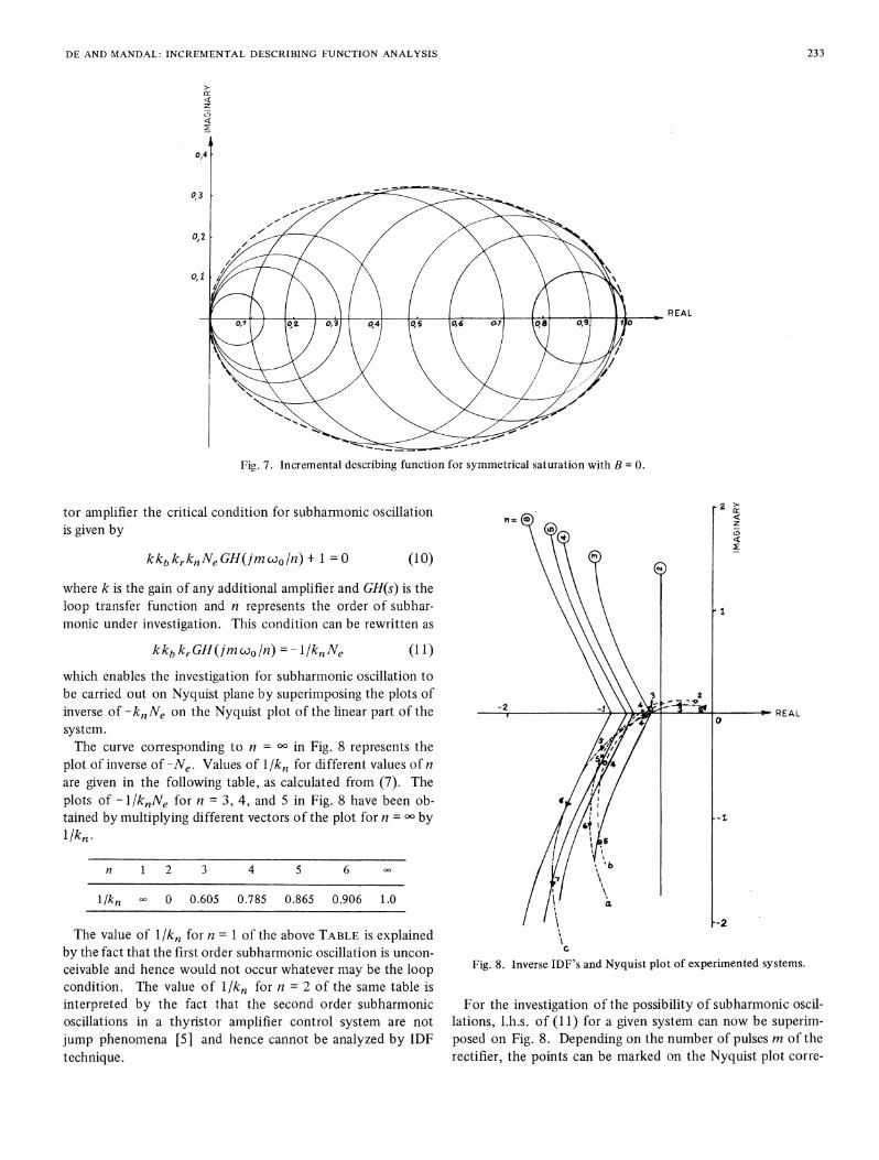
stabler behavior of rectifiers, the amplifier has been regarded as and N'(A) its rate of change with respect to A. For a fixeda linear element. Subharmonic oscillation is, however, asso- value of A, the amplitude of the sinusoidal component of in-ciated with the nonlinear character of a control system. For a put, the vector Ni(A), traces out a circle in the polar plane withthyristor amplifier the voltage saturation and the current block- radius AN'(A)/2 and center N(A) + AN'(A)/2 as the phase ofing feature are the primary sources of nonlinearity. Voltage the small test signal 0 is varied.saturation can be accounted for by cascading the linear portion IDF for a normalized symmetrical saturation type nonlin-of the model with a block having the symmetrical saturation earity has been derived in the Appendix as a function ofA andcharacteristic of Fig. 2. However, it has been shown in the the dc bias B. Fig. 7 shows the plot of the IDF's, given byforegoing section that the current blocking feature is in effect (19) and (20), for B = 0. The dotted curve shows the envelopea kind of saturation in the input-output relation. The depen- of all the circles. IDF's can similarly be drawn for other valuesdence of stoppage and resumption of conduction upon R, L, of B. It has, however, been found that the envelope of theand Eb of the load circuit makes the lower side of saturation IDF's for B = 0 encloses all other envelopes, corresponding tolevel greater than -E and variable. For the analysis of the sta- other values of B. Thus the dotted curve of Fig. 7 representsbility limit the actual level of saturation is of no consequence. the envelope of all the IDF plots of normalized symmetricalOnly the nature of the saturation characteristic matters, which, saturation type nonlinearity for all values of B and A .owing to current blocking feature, becomes in dynamic operat- Asymmetrical saturation type nonlinearities of the model ofing conditions unsymmetrical as shown in Fig. 5. thyristor amplifiers, as portrayed in Fig. 6, can be interpretedComparison of Fig. 4(a) with 4(b) shows that ripples, present after normalization as representing a symmetrical saturation
in a rectifier output, stand ignored in the composite model with an inherent bias. For the IDF technique of analysis, it issketched so far. The magnitude and frequency and phase of immaterial whether the bias B is generated by an external forc-ripple voltages depend on the pulse number of the rectifier ing function or is inherent in the nonlinearity itself. Therefore,converter and on the firing angle. For the present modeling the dotted curve of Fig. 7, to be denoted by Ne, represents asripples may be regarded as random signals. Effect of random well the envelope of IDF's of the nonlinearity of thyristorsignals upon the input-output relation of a saturation non- amplifiers, as portrayed in Fig. 6.linearity is a reduction of the gain [11 ]. Amount of reduction In a negative feedback control system, incorporating a thyris-
DE AND MANDAL: INCREMENTAL DESCRIBING FUNCTION ANALYSIS 233
z
030,4
0,3
REAL
Fig. 7. Incremental describing function for symmetrical saturation with B = 0.
tor amplifier the critical condition for subharmonic oscillation 2>is given by
kkbkrknNeGH(jmo0/n)+ 1 =0 (10)
where k is the gain of any additional amplifier and GH(s) is theloop transfer function and n represents the order of subhar- 1monic under investigation. This condition can be rewritten as
kkbkr Gf(jm wo/n) =- /kiNe (11)
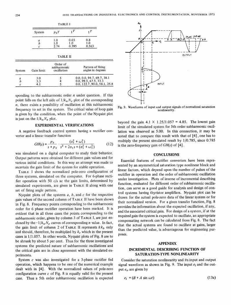
which enables the investigation for subharmonic oscillation tobe carried out on Nyquist plane by superimposing the plots of \ \2inverse of -knNe on the Nyquist plot of the hnear part of the -2 -j '-. REALsystem.The curve corresponding to n = oo in Fig. 8 represents the
plot of inverse of -Ne. Values of Il/kn for different values of nare given in the following table, as calculated from (7). Theplots of -I/knNe for n = 3, 4, and 5 in Fig. 8 have been ob-tained by multiplying different vectors of the plot for n = ooby -
I~~~~~~~~~~~~~~~~~~~~~~~~~ !/kn-n 1 2 3 4 5 6 00
1/k ° 0 0.605 0.785 0.865 0.906 1.0
n a\ --2The value of 1/kn for n = 1 of the above TABLE is explained
by the fact that the first order subharmonic oscillation is uncon- c
ceivable and hence would not occur whatever may be the loop Fig. 8. Inverse IDF's and Nyquist plot of experimented systems.condition. The value of l1/k0 for n = 2 of the same table isinterpreted by the fact that the second order subharmonic For the investigation of the possibility of subharmonic oscil-oscillations in a thyristor amplifier control system are not lations, l.h.s. of (11) for a given system can now be superim-jump phenomena [5] and hence cannot be analyzed by IDF posed on Fig. 8. Depending on the number of pulses m of thetechnique. rectifier, the points can be marked on the Nyquist plot corre-
234 IEEE TRANSACTIONS ON INDUSTRIAL ELECTRONICS AND CONTROL INSTRUMENTATION, NOVEMBER 1973
TABLE I eO
System p3T 1T 1T
II I\ nJ 2i/)
a 1.0 0.65 0.8 e _ J--.2(P)(2Pm )
b 1.0 1.0 1.0 /_0c 2.74 0.395 0.563 1
TABLE II OUTPUT
Order of lsubharmonic Pattern of firing
System Gain limit oscillation angles in degrees - 7
a 3.0 5 0.0,0.0,94.7, 69.7, 38.1b 3.3 4 0.0, 99.5, 67.5, 33.3c 4.1 5 0.0, 122.7, 90.0, 58.1, 25.8 _ INPUT
sponding to the subharmonic order n under question. If thispoint falls on the left side of l/knNe plot of the correspondingn, there exists a possibility of oscillation at this subharmonic
the system. The criticalvaluoFig. 9. Waveforms of input and output signals of normalized saturationfrequency to set in the system. The critical value of loop gam nonlinearity.is given by the condition, when the point of the Nyquist plotis just on the l/kn Ne plot.
beyond the gain 4.1 X 1.25/1.057 = 4.85. The lowest gainlimit of the simulated system for 5th order subharmonic oscil-
A negative feedback control system having a rectifier con- lation was observed as 5.00. In this connection, it may beverter and a linear transfer function noted that to compare this result with that of [4] , one has to
p3 _ _2 +_2_ multiply the present simulated result by 1/0.785, since 0.785GH(s)= 2 (+2 + (C(2 + (X2) (12) is the zero-frequency gain of GH(s) of [4].
was simulated on a digital computer to study their behavior. CONCLUSIONSOutput patterns were obtained for different gain values and forvarious initial conditions. In this way an attempt was made to Essential features of rectifier converters have been repre-ascertain the gain limit of the system for stable operation. sented by an asymmetrical saturation type nonlinear block and
TABLE I shows the normalized pole-zero configuration of linear factors, which depend upon the number of pulses of thethree systems, simulated on the computer. For 6-phase recti- rectifier in operation and the order of subharmonic oscillationfier operation with 50 c/s ac the gain limits, determined by under investigation. Plots of inverse of incremental describingsimulated experiments, are given in TABLE II along with one function, evaluated for different order of subharmonic oscilla-setoffiring.angle pattern, tion, can serve as a good guide for analysis and design of con-
set of firing angle pattern.Nyquist plots of the systems a, b, and c for the respective trol systems having thyristor amplifiers. Nyquist plot can be
gain values of the second column of TABLE II have been shown drawn for the actual pole-zero data of the linear system or for
in Fig. 8. Frequency points corresponding to the subharmonic their normalized version. For a given transfer function, Fig. 8
order for 6 phase rectifier operation have been marked. It is provides the information about the expected oscillation, if any,and the associated critical gain. For design of a system, if at the
evident that in all three cases the points corresponding to thereuie gai th syte isepcemoocllt,aprpit
subha~~~~~~~rmoiorde,gvnb oun3o TAL .,aejs n required gain the system is expected to oscillate, an appropriatesubhrmoicrde, gvenby olum 3 f TBLE1, re usten-compensating network can be calculated from Fig. 8. The factclosed by the - 1 /k,Ne curves of corresponding n value. In fact, compenating network ane cluld fromig. 8. The factthe gain limit of column 2 of TABLE II represents kkb only that the actual systems are found to oscillate at gains, larger
and should, therefore, be multiplied by kr which in the present tatepucases is 1/1.057. In other words, Nyquist plots of Fig. 8 are to poses.be shrunk by about 5 per cent. Thus for the three investigated APPENDIXsystems the predicted nature of subharmonic oscillations andthe critical gain are in close agreement with the simulated ex- INCREMENTAL DESCRIBING FUNCTION OFperiments. SATURATION-TYPE NONLINEARITYSystem c was also investigated for a 3-phase rectifier fed Consider the saturation nonlinearity and its input and output
operation, which happens to be one of the numerical example signal waveform as shown in Fig. 9. The input ei and the out-dealt with in [4] . With the normalized values of pole-zero put eO are given byconfiguration curve c of Fig. 8 is equally valid for the presentcase. Thus a 5th order subharmonic oscillation is expected ei= (B + A sin cot) (13a)

DE AND MANDAL: INCREMENTAL DESCRIBING FUNCTION ANALYSIS 235
eO =(B + A sin ot), 0 6 cut S a, r - a <Swt 6 r + Substituting these values in (16) we get2Tr- B < cot < 21- (13b)
=1,a < ct A 7r - a (I 3c) N1(A) [COS2 aA t + 2 tanf;3 ]= 1, 7r+ <3wt 27r- f3 (13d) 1
- [sin 27r + sin 2,]. (18)where AFT
sin a= (1 - B)/A (13e) Thus
and-1 AN'(A) = -1 [sin 2al + sin 2,B] (19)2ir
sin , =(1 +B)/A. (13f) 2The center of the IDF circle of (9) is given by
Expanding the output in Fourier series, we get
eo = E +a, sin ct + b, cos wt yi = N(A) + AN'(A)/2 = (a + ()/7r. (20)
+ higher harmonic terms (14a) ACKNOWLEDGMENT
=Eo + Ai sin (cut + (D) + higher harmonic terms (14b) The author is deeply grateful for the personal finance duringthis period of research to the Company. Facilities, made avail-
where able, for digital computation at the Computer Centre of I.I.T.,
a, = A/7r [a - ,B + (sin 2a)/2 + (sin 20)/2] (1 4c) Bombay, were also appreciated.
and b1 = 0. So, the describing function is given by REFERENCES
___ 1 sin 2at sin 213 [1] Parrish, E. A., Jr. and E. S. McVey, "A Theoretical Model forN(A) =-eilA = _
si
+,+ + 1. (15) Single-Phase Silicon-Controlled Rectifier Systems," IEEE Trans.A 1 3 2 2 J Automat. Contr., Vol. AC-12, No.5, 1967, pp. 577-579.
[2] Jackson, R. D., "Oscillations in Single Converter Drives," Proc.IEE, Vol. 116, No. 4, 1969, pp. 633-638.
For the computation of IDF, [3] Hazell, P. A., and J. 0. Flower, "Stability Properties of CertainThyristor-Bridge Control Systems, Pt. I and II," Proc. IEE, Vol.
1 dot do da do 117, No. 7, 1970, pp. 1405-1420.N'(A) =- -+- + cos 2a- + cos 213 [4] Faliside, F., and A. R. Farmer, "Ripple Instability in Closed Loop
rr dA dA dA dA] Control Systems with Thyristor Amplifiers," Proc. IEE, Vol. 114,No. 1, 1967, pp. 139-152.
2 2 da d11 [5] De, G., and A. K. Mandal, "Impulse Analysis of Subharmonic=- cos2C - + cos2 13-I. (16) Oscillations in Control Systems with Rectifier Converters," Ac-
7r dA dA Jcepted for publication in Proc. IEE, Paper No. 6994C.[6] Gelb, A., and W. E. Vander Velde, Multiple-Input Describing
Functions and Nonlinear System Design, McGraw-Hill Co., NewDifferentiating both sides of (1 3e) and rearranging we get York, 1968, p. 278.
[7] West, J. C., Analytical Techniques for Nonlinear Control Systems,
da 1 1 - B tan a The English University Press Ltd., 1960, p. 130.cos= - = . (1 7a) [8] Gupta, S. C., and Hasdorff, Fundamentals ofAutomatic Control,
dA cos a A2 John Wiley and Sons, New York, 1970, p. 430.[9] Fallside, F., C. J. Goodman and R. D. Jackson, "Stability of First
Order Sampling and Thyristor Systems," Electron. Letters, Vol.Similarly, 5, No. 22, 1969.
[10] Flower, J. O., and P. A. Hazell, "Nonlinear Analysis of First Orderda tan Thyristor Bridge Control System," Proc. IEE, Vol. 118, No. 10,
-- A -(17b) 1971,pp.1511-1516.dA A [11] Gelb and Vander Velde, op. cit., p. 592.