inclined disc spherical case: butterfly valve · fig. 5: section generated for flow area...
TRANSCRIPT

Inclined Disc Spherical Case: Butterfly Valve
M a r 2 0 1 3
Inclined Disc Spherical Case: Butterfly Valve | Mar 2013
© 2013, HCL Technologies, Ltd. Reproduction prohibited. This document is protected under copyright by the author. All rights reserved.
TABLE OF CONTENTS
Abstract ............................................................................................. 3
Abbreviations .................................................................................... 4
Market Trends/Challenges ................................................................ 6
Solution ............................................................................................. 7
Best Practices ................................................................................... 7
Common Issues .............................................................................. 12
Conclusion....................................................................................... 14
References ...................................................................................... 14
Author Info ....................................................................................... 14

Inclined Disc Spherical Case: Butterfly Valve | Mar 2013
© 2013, HCL Technologies, Ltd. Reproduction prohibited. This document is protected under copyright by the author. All rights reserved.
3
Abstract
The environment for aircraft passengers has to be controlled
precisely at the required temperature by cooling or heating the air by
mixing air streams of different temperatures. While mixing the air
streams, the mass flow of air has to be very precisely controlled.
This flow control is achieved by valves of specialized flow
characteristics to ensure that with a wider movement of the valve
disc, a small and precise increase in flow is achieved. Also, the
valve has to operate for both directions of flow and sustain extreme
low to high temperatures. The valve should also be leak tight when
closed. It should not get stuck while closing or opening. The
mechanical design should be robust and the disc should not come
out into the flow stream.

Inclined Disc Spherical Case: Butterfly Valve | Mar 2013
© 2013, HCL Technologies, Ltd. Reproduction prohibited. This document is protected under copyright by the author. All rights reserved.
4
Abbreviations
Sl. No. Acronyms Full Form
1 Amps Ampere, a unit for current
2 bar Unit of pressure
3 CAD Computer Aided Design
4 CV Flow coefficient of valve, i.e. flow delivered per unit
PSI pressure drop
5 °C Temperature in degrees centigrade scale
6 dP Pressure drop
7 DU Delivery unit
8 gram Unit of measuring weight
9 HVAC Heating ventilation and air conditioning
10 I Symbol for for electrical current
11 IIT Indian Institute of Technology
12 Kg Kilograms
13 Kg.M or Kg.m Unit for torque
14 min Minute, a unit of time
15 Max Maximum
16 N Rotational speed in revolutions per minute
17 N-m Newton meter, a unit to measure torque
18 OEM Original Equipment Manufacturer
19 P Power
20 Pd Pipe diameter
21 Pi A constant with value 22/7
22 PSI Pressure measured in pounds per square inch
23 Q Discharge
24 Rev Revolution
25 RPM Revolutions per minute
26 RPS Revolutions per second
27 Sd Diameter of the spherical surface of the valve
28 Sec Second, a unit of time

Inclined Disc Spherical Case: Butterfly Valve | Mar 2013
© 2013, HCL Technologies, Ltd. Reproduction prohibited. This document is protected under copyright by the author. All rights reserved.
5
29 Spec Specification
30 V An electrical unit for Voltage
31 VDC Voltage in Direct Current
32 W Watt, a unit of Power
33 w.r.t. With respect to
34 * Sign for multiplication
35 Ф Angle of inclination of the valve stem

Inclined Disc Spherical Case: Butterfly Valve | Mar 2013
© 2013, HCL Technologies, Ltd. Reproduction prohibited. This document is protected under copyright by the author. All rights reserved.
6
Market Trends/Challenges
The valve in this HCL internal project was conceptualised for cabin shut-off applications for the aerospace industry. This can also be used for other air handling applications such as HVAC. This concept was further checked for the variation of area of opening of the valve with its angle of opening. The gradual variation of flow area is required to achieve good flow control. It was also necessary to ensure that the disc/gate could be inserted from one end and should not come out from other end in case of shaft breakage so as to ensure safety concerns. The valve has to work for an air temperature range from -50° up to 180° C. and a pressure range up to 11.5 bar. It should withstand acceleration of up to 10 times gravity. It should deliver mass flow of 9.0 kg/min. Its weight should be less than 1.2 kg (max.) The allowable internal leakage should be less than 25 g/min at 6.0 bar and 180° C., and the external leakage should be less than 5 g/min at 6.0 bar and 180° C.
This valve was developed as
an internal project by HCL
Technologies.
This valve can be used in
Aerospace applications,
HVAC, and other applications
as well.
Inclined Disc Spherical Case: Butterfly Valve | Mar 2013
© 2013, HCL Technologies, Ltd. Reproduction prohibited. This document is protected under copyright by the author. All rights reserved.
7
Solution
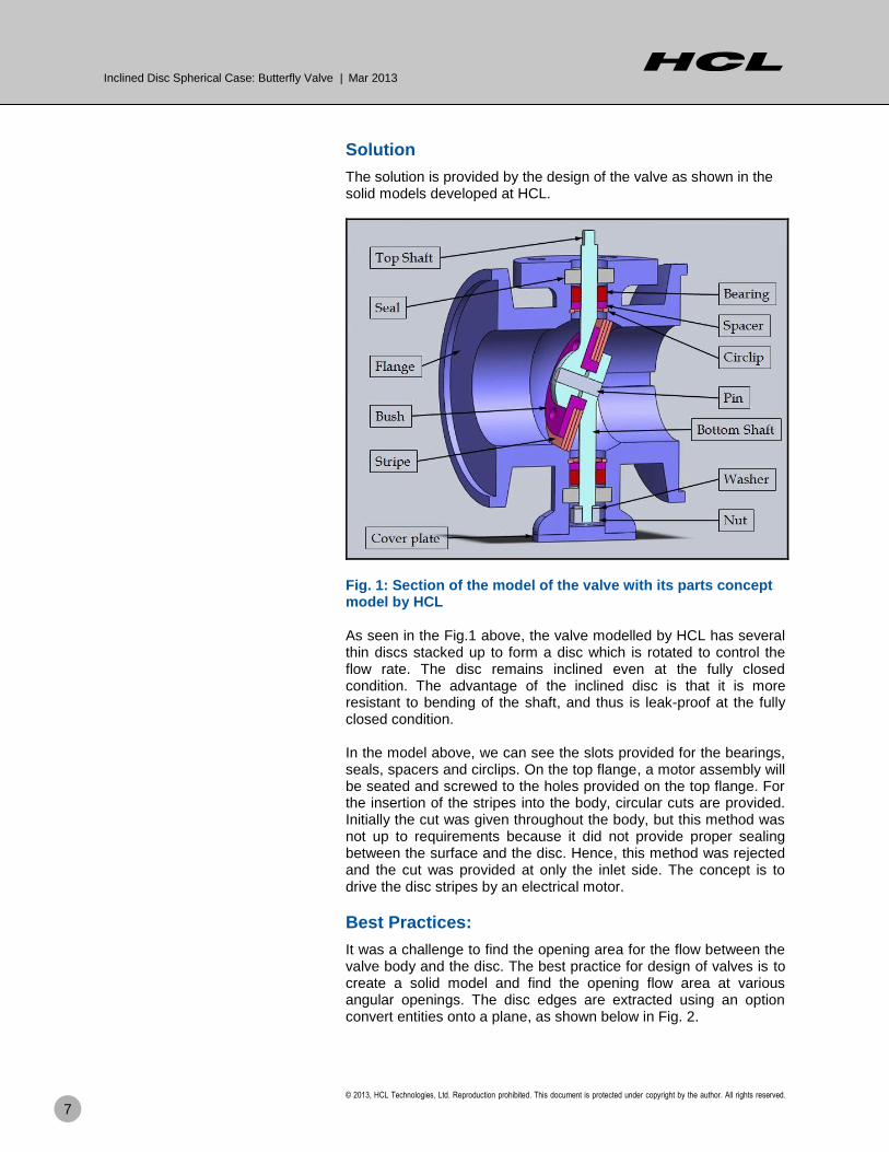
The solution is provided by the design of the valve as shown in the solid models developed at HCL.
Fig. 1: Section of the model of the valve with its parts concept model by HCL As seen in the Fig.1 above, the valve modelled by HCL has several thin discs stacked up to form a disc which is rotated to control the flow rate. The disc remains inclined even at the fully closed condition. The advantage of the inclined disc is that it is more resistant to bending of the shaft, and thus is leak-proof at the fully closed condition. In the model above, we can see the slots provided for the bearings, seals, spacers and circlips. On the top flange, a motor assembly will be seated and screwed to the holes provided on the top flange. For the insertion of the stripes into the body, circular cuts are provided. Initially the cut was given throughout the body, but this method was not up to requirements because it did not provide proper sealing between the surface and the disc. Hence, this method was rejected and the cut was provided at only the inlet side. The concept is to drive the disc stripes by an electrical motor.
Best Practices:
It was a challenge to find the opening area for the flow between the valve body and the disc. The best practice for design of valves is to create a solid model and find the opening flow area at various angular openings. The disc edges are extracted using an option convert entities onto a plane, as shown below in Fig. 2.

Inclined Disc Spherical Case: Butterfly Valve | Mar 2013
© 2013, HCL Technologies, Ltd. Reproduction prohibited. This document is protected under copyright by the author. All rights reserved.
8
Fig 2: The disc edges extracted using an option Convert Entities After finishing the sketch, a new part is created inside an assembly with the extracted edges of the disc, as shown in Fig. 3.
Fig 3: Assembly with the extracted edges of the disc Now the sketch is modified with respect to the inner diameter of the pipe, and the sketch is modelled as shown in Fig. 4.

Inclined Disc Spherical Case: Butterfly Valve | Mar 2013
© 2013, HCL Technologies, Ltd. Reproduction prohibited. This document is protected under copyright by the author. All rights reserved.
9
Fig. 4. Sketch is modified w.r.t. the inner diameter of the pipe After finishing the model, the flow area is calculated from the section generated as shown below in Fig. 5.
Fig. 5: Section generated for flow area calculation
Inclined Disc Spherical Case: Butterfly Valve | Mar 2013
© 2013, HCL Technologies, Ltd. Reproduction prohibited. This document is protected under copyright by the author. All rights reserved.
10
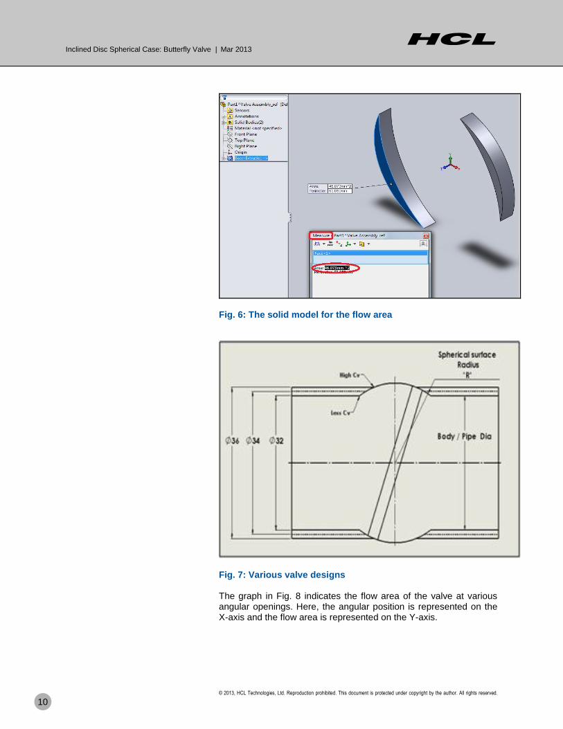
Fig. 6: The solid model for the flow area
Fig. 7: Various valve designs The graph in Fig. 8 indicates the flow area of the valve at various angular openings. Here, the angular position is represented on the X-axis and the flow area is represented on the Y-axis.

Inclined Disc Spherical Case: Butterfly Valve | Mar 2013
© 2013, HCL Technologies, Ltd. Reproduction prohibited. This document is protected under copyright by the author. All rights reserved.
11
Fig. 8: Flow area versus angular opening for various valves The opening areas, when plotted with reference to the angular opening of the valve, give an idea as to whether the valve is opening suddenly or gradually. From this curve as plotted, we learn about the valve characteristics. This saves several runs for the CFD. However, the final configuration of the valve selected may be used for the CFD analysis to benchmark the hand calculations with the CFD results. Fig. 9: Valve % flow area versus disc opening
0
20
40
60
80
100
120
0° 10° 20° 30° 40° 50° 60° 70° 80° 90°
% Area for Pd = 32
% Area for Pd = 34
X-Axis; %Openingv/s
Y-Axis; % Area
Ф=20º
Sd=38mm

Inclined Disc Spherical Case: Butterfly Valve | Mar 2013
© 2013, HCL Technologies, Ltd. Reproduction prohibited. This document is protected under copyright by the author. All rights reserved.
12
The graph in Fig. 9 shows the variation of the %Area of opening with respect to the change in pipe radius values. Also, we can observe the results of the inclined disc valve with respect to the vertical valve. From Fig. 9 we can observe that, with the same spherical surface, we can achieve higher flow co-efficient values by varying the pipe diameter respectively
Angle of inclination, Ф = 20º
Sphere dia, (Sd) Pipe dia, (Pd) Sd / Pd
38mm 32mm 1.188
38mm 34mm 1.118
38mm 36mm 1.056
Common Issues
The simple calculation for finding the torque value of this valve is shown below.
Input
Volts in 'VDC' 28
Amphere 'Amps' 0.8
Power(P) 'W' V*I
23
Max./Min. Operating time
9secs/6 Secs
Max. RPS (1/4rev/6 Secs)= (1/24) rps
RPM =1/24*60 = 2.5
w(Rad/sec)= 2.Pi. N/60
= 0.2617
Torque in N-m = Power/ w = 87.88
From the calculations above, it is concluded that the motor required will be 28 Volts with 0.8 Amps current. Thus the power required will be 23 Watts. The opening time will be 6 to 9 seconds. The max RPM will be 2.5 and the torque will be T=Power/w = 88 N-m
Inclined Disc Spherical Case: Butterfly Valve | Mar 2013
© 2013, HCL Technologies, Ltd. Reproduction prohibited. This document is protected under copyright by the author. All rights reserved.
13
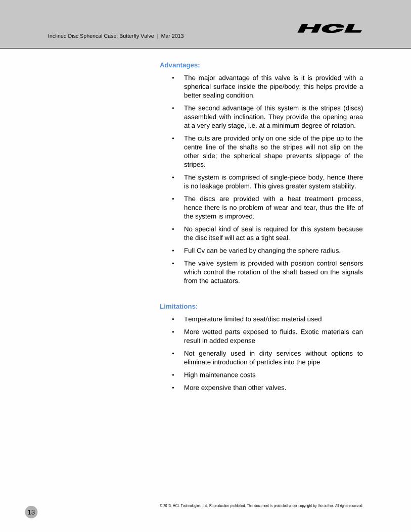
Advantages:
• The major advantage of this valve is it is provided with a
spherical surface inside the pipe/body; this helps provide a
better sealing condition.
• The second advantage of this system is the stripes (discs)
assembled with inclination. They provide the opening area
at a very early stage, i.e. at a minimum degree of rotation.
• The cuts are provided only on one side of the pipe up to the
centre line of the shafts so the stripes will not slip on the
other side; the spherical shape prevents slippage of the
stripes.
• The system is comprised of single-piece body, hence there
is no leakage problem. This gives greater system stability.
• The discs are provided with a heat treatment process,
hence there is no problem of wear and tear, thus the life of
the system is improved.
• No special kind of seal is required for this system because
the disc itself will act as a tight seal.
• Full Cv can be varied by changing the sphere radius.
• The valve system is provided with position control sensors
which control the rotation of the shaft based on the signals
from the actuators.
Limitations:
• Temperature limited to seat/disc material used
• More wetted parts exposed to fluids. Exotic materials can
result in added expense
• Not generally used in dirty services without options to
eliminate introduction of particles into the pipe
• High maintenance costs
• More expensive than other valves.
Inclined Disc Spherical Case: Butterfly Valve | Mar 2013
© 2013, HCL Technologies, Ltd. Reproduction prohibited. This document is protected under copyright by the author. All rights reserved.
14
Conclusion
Using the valve to control pump flow causes a loss in energy, hence
the concept of an engageable and dis-engageable impeller pump is
good for the purpose of energy saving and meeting the
requirements of varying flow and pressure.
Reference
1. The source for this white paper is the HCL internal project at
the Aero Delivery Unit. This is not related to work for any
customer.
Author Info
Chandrasekaran S R
HCL Technologies, Ltd., Bangalore.
Has earned his Master’s degree in Mechanical Engineering and has over 38 years of experience in a premier Research and Development Organization. His entire service was in the R&D Organization and India defense.
His trainings and additional qualifications are
MBA (HRD),SFI (West Germany-Welding Specialist Engineer from Welding Research Institute, Hamburg), AM Ae SI (Design and Production)
Dr. R. S. Madhusudan,
Head Solutions & Group Technical Specialist,
HCL Technologies, Ltd., Bangalore.
Dr. Madhusudan earned his Masters and
Doctorate degrees in Mechanical Engineering from
IIT Madras. He has 25 years of experience in
developing new products in hydraulics.
Karunakara Talawara,
Technical Lead, HCL Technologies, Ltd.,
Bangalore.
He earned his Masters degree in Mechanical
Engineering (Turbo machines) from IIT Madras,
and has 10 years of industrial experience with
OEMs in centrifugal pumps and positive
displacement pumps
Inclined Disc Spherical Case: Butterfly Valve | Mar 2013
© 2013, HCL Technologies, Ltd. Reproduction prohibited. This document is protected under copyright by the author. All rights reserved.
15
Ashok Manohar Pujar,
Group Project Manager, HCL Technologies, Ltd.,
Bangalore
He earned his Masters in Technology from
Visveswaraiah Technological University, Belgaum.
He has 17+ years of experience in a variety of
fields. His specialization is in hydraulics, and he has
worked on industrial and defense related hydraulic
systems development, valves, and actuator design.
Sharan Babu K.,
Member Technical Staff, HCL Technologies, Ltd., Bangalore.
He earned his Bachelor’s degree in Mechanical
Engineering from Visveswaraiah Technological
University, Belgaum. He has 2+ years of industrial
experience in gears, shafts and pinions, valves
and rotating equipment for petrochemical
applications.
.

Hello, I’m from HCL’s Engineering and R&D Services. We enable technology-led organizations to go to market with innovative products and solutions. We partner with our customers in building world class products and creating associated solution delivery ecosystems to help bring market leadership. We develop engineering products, solutions and platforms across Aerospace and Defense, Automotive, Consumer Electronics, Software, Online, Industrial Manufacturing, Medical Devices, Networking & Telecom, Office Automation, Semiconductor and Servers & Storage for our customers.
For more details contact [email protected]
Follow us on Twitter: http://twitter.com/hclers
Visit our blog: http://www.hcltech.com/blogs/engineering-and-rd-services
Visit our website: http://www.hcltech.com/engineering-services/
About HCL
About HCL Technologies HCL Technologies is a leading global IT services company, working with clients in the areas that impact and redefine the core of their businesses. Since its inception into the global landscape after its IPO in 1999, HCL focuses on “transformational outsourcing” underlined by innovation and value creation, and offers an integrated portfolio of services including software-led IT solutions, remote infrastructure management, engineering and R&D services and BPO. HCL leverages its extensive global offshore infrastructure and network of offices in 26 countries to provide holistic, multi-service delivery in key industry verticals including Financial Services, Manufacturing, Consumer Services, Public Services and Healthcare. HCL takes pride in its philosophy of “Employees First, Customers Second,” which empowers our 85,194 transformers to create a real value for the customers. HCL Technologies, along with its subsidiaries, has reported consolidated revenues of US$ 4.4 billion (Rs. 23499 crores), as on TTM ended Dec 31 '12. For more information, please visit www.hcltech.com
About HCL Enterprise HCL is a $6.2 billion leading global technology and IT enterprise comprising two companies listed in India - HCL Technologies and HCL Infosystems. Founded in 1976, HCL is one of India's original IT garage start-ups. A pioneer of modern computing, HCL is a global transformational enterprise today. Its range of offerings includes product engineering, custom and package applications, BPO, IT infrastructure services, IT hardware, systems integration, and distribution of information and communications technology (ICT) products across a wide range of focused industry verticals. The HCL team consists of over 90,000 professionals of diverse nationalities, who operate from 31 countries including over 500 points of presence in India. For more information, please visit www.hcl.com