in-situ chemical oxidation (isco) experiences from a ... · 2 fundamentals of in-situ chemical...
TRANSCRIPT

English translationReprint from
Handbuch der Altlastensanierung
In-situ Chemical Oxidation (ISCO)Experiences from a successful
source remediation project
byDr. Hans-Georg Edel
Co-Authors:Markus Friedrich
Dr. Hubert GerweckHerbert Stäblein
Wolfgang Maier-Oßwald
Züblin Umwelttechnik GmbHMaulbronner Weg 32, 71706 MarkgröningenTel. +49 7145 9324-0Fax +49 7145 [email protected]
Stuttgart, Berlin, Chemnitz, Dortmund, Hamburg, Nürnberg,Frankreich, Italien, Schweiz, Chile, China

6

In-situ Chemical Oxidation (ISCO)Experiences from a successful source
remediation project
Dr. Hans-Georg Edel, Stuttgart, Markus Friedrich, B�blingen, Dr. Hubert Ger-weck, T�bingen, Herbert St�blin, T�bingen, Wolfgang Maier-Oßwald, Stuttgart
Contents
Margin No.1 Summary 1 – 42 Fundamentals of in-situ chemical oxidation 5 – 272.1 Oxidants typically applied in practice 9 – 272.1.1 Permanganate 13 – 212.1.2 Peroxodisulfate 22 – 242.1.3 Fenton’s reagent 25 – 273 ISCO cleanup projects in practice 28, 294 First full-scale ISCO cleanup project in Germany 30 – 884.1 Background 30 – 404.2 Geological subsurface conditions 41 – 444.3 Hydrogeological conditions 45 – 474.4 Contaminant distribution in the groundwater 48 – 514.5 Remediation permit and other legal aspects 524.6 Cleanup implementation 53 – 834.6.1 Laboratory test 55 – 574.6.2 Pilot-scale test 58 – 634.6.3 Remediation test 64 – 744.6.4 Remediation 75 – 834.6.4.1 Phase 1 794.6.4.1 Phase 2 804.6.4.1 Phase 3 814.6.4.1 Phase 4 82, 834.7 Results 84 – 885 Outlook 89 – 91
Authors’ business addresses
Janss Aufsatz Sonderausgabe Version: 2011–06–01 HdA
S. 1
1
1

Keyword overview according to margin numbers
Bochinger horizon 42, 45 f.Chlorinated ethylenes 18, 56Cleanup target 2, 75Contamination centre 1, 42, 48, 61, 75,
86 f.CVOCs 2 f., 28, 30, 35 f., 48 f., 56, 61 – 64,
69 f., 73, 81 f., 84 – 87, 90Dark red marls 42DNAPL 20Downgradient protection 40, 82Feasibility study 37 f.Fenton’s reagent 9, 14, 24, 26 f.Field test 52, 55, 91Final product 16, 23, 27Fissured aquifer 45Groundwater model 35, 49Gypsum bottom layer 42Hydroxyl radical 25 – 27In-situ chemical oxidation 1, 4, 22, 39, 53,
87, 89Intermediate product 16, 23, 27ISCO 1, 4 – 6, 8, 11, 16, 24, 28, 40, 52 f., 58,
64, 75 f., 78, 82, 87 – 91Isotope analysis 35, 50Keuper gypsum 28 f., 42, 45Laboratory test 54LC-MS screening 3, 74, 82Manganese dioxide 14, 18, 20 f.Mobile in-situ test facility 91Molecular reaction 14Monitoring programme 2, 53, 62, 82
Occupational health & safety 52Permanganate 1, 3, 9, 13 – 16, 18, 22 –
24, 26, 29, 57, 60 f., 63, 65 f., 68 f., 73,76 f., 81
Permanganate injection 2, 58 – 59, 69,82
Peroxodisulfate 21Persulfate 9, 14, 22 – 24, 26Pilot-scale test 58, 60 f., 64Public law contract 40Pump-and-treat 1, 40, 75, 77, 82, 87Radical reaction 23, 27Radius of influence 14, 23, 27Rebound 2, 82Redox potential 14, 23, 25, 62, 69, 73Reductive dehalogenation 16, 50Remediation practice 9Remediation test 28, 52, 64 f.ROI 14SOD 11Source remediation 3, 8, 28, 53Sulfate radical 23
Janss Aufsatz Sonderausgabe Version: 2011–06–01 HdA
S. 2
In-situ Chemical Oxidation (ISCO)
2
2
1 Summary
In-situ chemical oxidation (ISCO) is a new and very promising remedia-tion technology. In Germany, a first full-scale project has been carried out atthe production site of an automotive manufacturer [1–5]. The cleanup of thecontamination centre was successfully completed after a period of 32months. The result has shown that the innovative ISCO method using per-manganate was, in this case, not only technically suitable but also morecost-effective compared with the conventional pump-and-treat method.
The CVOC concentrations at this site, which has been in industrial use forsome 90 years, peaked at 50 mg/l prior to groundwater remediation. Therewas an urgent need for remediation in order to avoid further spreading ofthe contamination and minimize the hazard to the lower groundwater hori-zons. A specific cleanup target was deliberately not laid down by the rele-vant public authority. However, the objective was to reduce the contaminantcontents by around 80–90 % within 2–3 years. From September 2005 untilMay 2008, approximately 30 t of oxidant were injected into the contamina-tion centre, and after conclusion of the active cleanup measures an extensi-ve monitoring programme was put in place. If follow-up monitoringshould indicate a rebound at individual wells, this will be dealt with bysystematic permanganate injections.
About two and a half years after completion of the source remediation, theoutcome of the measures implemented so far can be regarded as very satis-factory [6, 7]. The contaminant concentrations at the centre have on averagebeen reduced by approx. 90 % and range from 0.1–2.5 mg/l CVOCs. In thedowngradient plume, an average reduction of 85 % was achieved down toCVOC concentrations of . 1 mg/l. By means of LC-MS screening it wasverified that in-situ chemical oxidation with permanganate does not createany harmful degradation products. It is estimated that approx. 7,500–10,000 kg of CVOCs have been destroyed through oxidation.
This first full-scale, successful ISCO project was the starting point for anumber of pilot-scale tests and cleanup projects, which were able to providefurther insights and experiences. Some of these projects have meanwhilealso been completed. At present, in-situ chemical oxidation is the most wi-dely employed innovative remediation method and has become firmly esta-blished in the market [7].
Janss Aufsatz Sonderausgabe Version: 2011–06–01 HdA
S. 3
In-situ Chemical Oxidation (ISCO)
3
1
2
3
4
3

2 Fundamentals of in-situ chemical oxidation
The functional principle of in-situ chemical oxidation (ISCO) essentiallyconsists of introducing suitable oxidants into the subsurface and distribu-ting them there in order to eliminate the existing contaminants in situ(Fig. 1).
The ISCO method for subsurface remediation was developed in the USAand recognized by the USA’s Environmental Protection Agency (EPA) as aviable in-situ remediation method [8, 9].
Fig. 1: ISCO – in-situ chemical oxidation, process principle
It is primarily suitable for source remediation involving contaminants inthe medium to upper concentration range. One of ISCO’s particular advan-tages is that the cleanup duration can be considerably shortened, comparedwith conventional methods, thanks to the fast destruction of contaminants.
2.1 Oxidants typically applied in practice
The oxidant mainly used in remediation practice is permanganate; recentlypersulfate has also been applied and in specific cases Fenton’s reagent hasbeen the chosen oxidant (Table 1).
Janss Aufsatz Sonderausgabe Version: 2011–06–01 HdA
S. 4
In-situ Chemical Oxidation (ISCO)
4
5
6
7
8
9
4

Table 1: Oxidants typically used for ISCO projects
Oxidant Redox equation Eh [V]
Permanganate MnO4– + 4 H+ + 3 e– R MnO2 + 2 H2O 1.7
Peroxodisulfate S2O82– + 2 H+ + 2 e R 2 HSO4
– 2.1
Peroxodisulfate, act. S2O82– CAT ? SO4
– + SO42–
——R 2.7
Fenton’s reagent H2O2 Fe2+ ? OH + OH–—R 2.8
Table 2 lists the contaminants that can be destroyed by the above oxidants.However, the oxidants do not react specifically with these contaminants,but also generally with other oxidizable compounds as occur naturally inthe soil matrix. The actual soil oxidant demand (SOD) will therefore notonly depend on the given contaminants; it must also take account of thetype of soil and its natural organic content. For large soil masses with a veryhigh SOD, remediation using the ISCO method is not a cost-effective solu-tion.
Table 2: Oxidizability of different contaminants, adapted from [9]++ very good, + good, – poor
Contaminant
Oxidant
Permanga-nate
Peroxo-disulfate
Persulfate,activated
Fenton’sreagent
Chlorinated ethylenes ++ + ++ ++
Chlorinated ethanes – – +/++ +/–
Chlorinated methanes – – –/+/++ +/–
HC + + ++ ++
BTEX + + ++ ++
Benzene – + +/++ ++
PAH +/++ + +/++ +/++
MTBE + –/+ ++ +/++
Janss Aufsatz Sonderausgabe Version: 2011–06–01 HdA
S. 5
In-situ Chemical Oxidation (ISCO)
5
10
11
12
5

2.1.1 Permanganate
Permanganate is available as potassium salt or sodium salt, KMnO4 as acrystalline salt and NaMnO4 as a solution. The two different states do prin-cipally not differ in terms of oxidant properties.
With a redox potential of 1.7 V, permanganate is a mild oxidant comparedwith persulfate or Fenton’s reagent (Table 1). It is stable and can be trans-ported over relatively long distances, so that it has an extensive radius ofinfluence (ROI). Permanganate reacts quickly and its efficiency is fairly un-affected by the pH value. In the pH range from 3.5-12, which is relevant formost applications at natural sites, the oxidation action of permanganate un-folds while accepting three electrons, thus producing low-solubility manga-nese dioxide (MnO2). During this process the oxidation level of manganeseis reduced from +VII to +IV. Oxidation with permanganate is based on amolecular reaction.
Due to its electrophilic properties, permanganate preferably reacts withC = C double bonds. Apart from ethylenes, it is also possible to oxidize phe-nols, activated aromatics and other contaminants, but not methanes, ethanesor benzene (Table 2).
The ISCO method with permanganate is most frequently employed to de-stroy chlorinated ethylenes found on sites with contamination legacies, na-mely tetrachloroethylene (PCE), trichloroethylene (TCE), cis-1,2-dichloroe-thylene (cDCE), chloroethylene or vinyl chloride (VC). The degradationpathway of these compounds has been well studied [10]. They are oxidizedvia an intermediate stage from glycols to carboxylic acids and finally to CO2(Fig. 2). The intermediate products of the chemical oxidation of chlorinatedethylenes are only short-lived when permanganate is chosen as an oxidant.It should be specially noted that oxidation with permanganate does not re-sult in any harmful intermediate or final products, in contrast to reductivedehalogenation.
Janss Aufsatz Sonderausgabe Version: 2011–06–01 HdA
S. 6
In-situ Chemical Oxidation (ISCO)
6
13
14
15
16
6

Fig. 2: Oxidation of PCE, proposal for reaction mechanism, adapted from [10]
Janss Aufsatz Sonderausgabe Version: 2011–06–01 HdA
S. 7
In-situ Chemical Oxidation (ISCO)
7
17
7

The reaction equations for the complete oxidation of the chlorinated ethyle-nes PCE, TCE, cDCE and VC are set out in Table 3. Higher chlorinatedethylenes (PCE, TCE) require less permanganate for complete oxidationand therefore produce less manganese dioxide than low-chlorinated ethy-lenes (cDCE, VC). However, the latter are converted at a faster rate than thehigher chlorinated ethylenes [8].
Table 3: Oxidation of chlorinated ethylenes using permanganate, reactionequations
Tetrachlororethylene (PCE)4 MnO4
– + 3 C2Cl4 + 4 H2O R 6 CO2 + 4 MnO2 + 8 H+ + 12 Cl–
Trichloroethylene (TCE)2 MnO4
– + C2HCl3 R 2 CO2 + 2 MnO2 + H+ + 3 Cl–
Dichloroethylene (cDCE)8 MnO4
– + 3 C2H2Cl2 R 6 CO2 + 8 MnO2 + 6 Cl– + 2 OH– + 2 H2O
Vinyl chloride (VC)10 MnO4
– + 3 C2H3Cl R 6 CO2 + 10 MnO2 + 3 Cl– + 7 OH– + H2O
In principle, the permeabilities in the aquifer can be reduced by the precipi-tation of low-solubility manganese dioxide. Particularly in areas with high-ly concentrated contaminant accumulations, i.e. in DNAPL pools, the fastoxidation of chlorinated hydrocarbons can be delayed, which consequentlyimpairs the cleanup effectiveness in these areas.
In batch and column tests with artificially contaminated soils, it has beenfound that the hydraulic conductivity was reduced due to the formation ofmanganese dioxide. In the case of coarse sand soils, the conductivity increa-sed again when the test included intermittent flushing with water [11]. Inpractice, however, several applications with well permeable aquifers didnot show a reduction in their permeabilities [7]. To a limited extent, MnO2precipitations can also have an oxidizing effect on chlorinated hydrocarbonsand certain other organic compounds [12]. The low-solubility manganesedioxide is then reduced to soluble Mn2+.
2.1.2 Peroxodisulfate
The oxidant peroxodisulfate, also known as persulfate, represents an inter-esting alternative or addition to permanganate application. For in-situ che-mical oxidation it is mainly used as a sodium salt.
Janss Aufsatz Sonderausgabe Version: 2011–06–01 HdA
S. 8
In-situ Chemical Oxidation (ISCO)
8
18
19
20
21
22
8
Persulfate is a stable oxidant which can be transported over relatively longdistances and, like permanganate, therefore has an extensive radius of in-fluence. It has a redox potential of 2.1 V and shows only a low affinity toorganic soil constituents, so that the soil oxidant demand is low [13]. Usingcatalysts or applying temperatures above 40 �C, generates the sulfate radi-cal, which has a very high redox potential of 2.7 V (Table 1). Contaminantoxidation by means of activated persulfate involves a radical reactionwhich can form numerous intermediate and final products.
The application of persulfate makes it possible to oxidize contaminants thatcannot be dealt with by permanganate, i.e. benzene and PAH as well asmethanes, ethanes and MTBE [9]. With the ISCO method, persulfate is em-ployed as an aqueous solution in the neutral pH range. This may lead to atemporary enrichment of sulfate and can, depending on the permeability ofthe aquifer, create conditions aggressive to concrete.
2.1.3 Fenton’s reagent
Fenton’s reagent is an oxidant arising from the activation of H2O2 with Fe2+.This generates hydroxyl radicals with a very high redox potential of 2.8 V(Table 1). The pH optimum of the classic Fenton’s reaction lies around 3–4.With the aid of chelated Fe2+ ions it can also take place in the neutral pHrange.
Fenton’s reagent has a very broad spectrum of application. It destroys allthe contaminants that can also by oxidized by permanganate or persulfate[9]. As an initial product one usually employs concentrated H2O2 solutionswhich are activated by FeSO4 solutions. The reaction is accompanied by aconsiderable heat and gas generation in the form of O2 and CO2 and is notwithout danger.
The hydroxyl radical is very unstable and quickly decomposes in the sub-surface. For this reason it can only be transported over short distances andhas a radius of influence limited to only a few metres. Carbonates act asradical traps and can greatly reduce the efficiency of Fenton’s reagent. Thereaction mechanism of the Fenton’s reaction is driven by a radical reactionwhich forms numerous intermediate and final products.
Janss Aufsatz Sonderausgabe Version: 2011–06–01 HdA
S. 9
In-situ Chemical Oxidation (ISCO)
9
23
24
25
26
27
9
3 ISCO cleanup projects in practice
After preparatory bench-scale and field investigations followed by a reme-diation test, the first full-scale ISCO cleanup project in Germany commen-ced in September 2005 at the site of an automotive manufacturer in Sindel-fingen [1, 2]. It involved the source remediation of CVOC groundwatercontamination in the Keuper gypsum. The project, which is described be-low in further detail, was successfully completed in May 2008 after a reme-diation period of 32 months.
Since then several other ISCO projects have been undertaken in Germanyand across Europe; some of them have been concluded while others are stillbeing implemented [7]. Therefore, the ISCO method can currently be regar-ded as the most frequently chosen innovative remediation method, whichhas become firmly established in the market. The ISCO method with per-manganate as an oxidant has also been positively assessed by the workingcommittee „Innovative In-situ Remediation Methods“ of the ITVA (GermanScientific-technical Association for Environmental Remediation and Brown-field Redevelopment) [14].
4 First full-scale ISCO cleanup project in Germany
4.1 Background
The project site, which has been in industrial use for some 90 years, exhibi-ted massive contamination of the groundwater in the Keuper gypsum. TheCVOC concentrations, whose origin could not identified despite extensiveinvestigation, peaked at 50 mg/l. Remediation was required in order toavoid further spreading of the contamination and minimize the hazard tothe lower groundwater horizons. A number of different site-specific fac-tors – e.g. the complex hydrogeological conditions and the continued use ofthe contaminated area as a customer centre – had to be taken into account(Fig. 3).
Janss Aufsatz Sonderausgabe Version: 2011–06–01 HdA
S. 10
In-situ Chemical Oxidation (ISCO)
10
28
29
30
10

Fig. 3: Drilling work for the remediation wells in front of building 25/1
The contamination zone is located in the east of the works site. This areawas part of the former B�blingen airfield which was used by the US ArmedForces for a long time after the war. Today most of the contamination zoneis covered by the buildings of a heat & power plant and the company’s cu-stomer centre.
The exploration of the existing environmental damage and the search forthe polluter responsible were carried out in accordance with the procedurecustomary in Baden-W�rttemberg. It involved the following step-by-stepmeasures:
• Historical investigation
• Multitemporal aerial photography evaluation
• Pumping tests for determining the hydraulic characteristics
• Installation of 12 groundwater monitoring points
• Probings in the suspected contamination centre with soil air analyses
Janss Aufsatz Sonderausgabe Version: 2011–06–01 HdA
S. 11
In-situ Chemical Oxidation (ISCO)
11
31
32
33
34
11

• E3-4 study (thorough assessment for remedial measures/cleanup pre-planning)
Isotope analyses (13C signature) for delimiting the CVOC contamination are-as in the surroundings of the works site and a transport simulation bymeans of an existing groundwater model were carried out in addition.
The above investigations provided good information about the size and ex-tent of the groundwater contamination. However, it was not possible totrack down the origin of the contaminants and contaminant source. Tetra-chloroethylene (PCE) was found to be the dominant contaminant parame-ter. The CVOC concentrations originally reached a maximum of 50 mg/l.
Within the framework of the feasibility study (E3-4 study) on groundwaterremediation various methods were examined in detail. They had to satisfythe following site-specific factors:
• Deep-lying fissured aquifer
• Extensive spread of the contamination plume through built-over area
• Consideration for the use of the affected works area as a customer centrewhere some 600 new vehicles are personally collected by customers eve-ry working day
• Risk of so far undetected old explosive devices in the subsurface resul-ting from several bombardments of the works site and the former airfieldduring World War II.
• Multiple branched network of supply lines and sewer conduits
The feasibility study examined a number of innovative remediation me-thods hitherto not very well known in Germany but already tested in theUSA. As a result of the study, in-situ chemical oxidation was recommen-ded as the method that can be most effectively implemented in compliancewith the given site-specific factors. Apart from the site-specific reasons, itwas decisive for the selection of this method that the high contaminant con-centrations in the groundwater could potentially be effectively reduced wi-thin a relatively short period of time, thus decreasing the existing contami-nant and hazard potential.
The District Administration of B�blingen, as the Lower Water Authority,and the affected industrial company, as the site owner, were in agreementthat further cost-intensive measures for determining the input source and apossible polluter responsible for the damage would not be goal-oriented.The start of the groundwater cleanup was seen as the priority, especially in
Janss Aufsatz Sonderausgabe Version: 2011–06–01 HdA
S. 12
In-situ Chemical Oxidation (ISCO)
12
35
36
37
38
39
40
12

order to stop further spreading, e.g. the migration of contaminants into dee-per groundwater horizons. For this purpose, a public law contract was con-cluded between the industrial company concerned and the state of Baden-W�rttemberg, represented by the District Administration of B�blingen. Itspecifies the further steps for implementing the cleanup project, such as thestipulations for the application of the ISCO method together with a pump-and-treat measure for downgradient protection.
4.2 Geological subsurface conditions
The area of investigation lies in the northeast to southwest valley plain ofthe watercourses Schwippe and Murkenbach. The two brooks were rerou-ted in the 1970s and partly buried in underground conduits. The naturalsubsurface is composed of Quaternary valley deposits, interlocking in someareas with mud. The Quaternary deposits consist of a very variably structu-red sequence of clay, silt, sand, and fine gravel, interspersed with 0.5–3.0 mthick layers of peat, as well as of mixed-grain mud fractions. The thicknessof the Quaternary deposits ranges from approx. 3.5 m to 15.0 m.
Further down lies the stratigraphic sequence of the Keuper gypsum, en-compassing the units dark red marl, Bochinger horizon, and gypsum bot-tom layers. The dark red marls are mostly reddish-brown, clayey silt soilswith individual leached gypsum residues and friable, layered silty claysto-nes. The layers of the underlying Bochinger horizon are composed primari-ly of claystones and silty claystones with leached gypsum residues and do-lomitic beds. In the boreholes the thickness of the Bochinger horizon is be-tween 4.6 m and 5.8 m. Further down the Bochinger horizon is succeededby extensively leached gypsum bottom layers consisting of silty claystonesincorporating numerous leached gypsum residues as well as residual siltsand marly beds. Towards the east and southeast there are also thicker gyp-sum layers. Gypsum leaching can produce cavities which are reproducedby the overlying layers. In the area of the contamination centre a doline-type structure with its lowest point near monitoring points GWM 3423 andGWM 3439 was encountered. Fig. 4 is a schematic cross-section in west-eastdirection through the investigation area, also showing the depression. As anexample, Fig. 5 depicts the stratigraphic sequence of the borehole for moni-toring point 3439.
Janss Aufsatz Sonderausgabe Version: 2011–06–01 HdA
S. 13
In-situ Chemical Oxidation (ISCO)
13
41
42
13
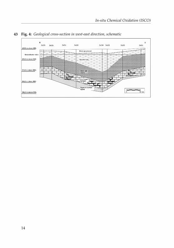
Fig. 4: Geological cross-section in west-east direction, schematic
Janss Aufsatz Sonderausgabe Version: 2011–06–01 HdA
S. 14
In-situ Chemical Oxidation (ISCO)
14
43
14

Fig. 5: Stratigraphic profile, monitoring point 3439
Janss Aufsatz Sonderausgabe Version: 2011–06–01 HdA
S. 15
In-situ Chemical Oxidation (ISCO)
15
44
15

4.3 Hydrogeological conditions
The investigation area shows two groundwater storey formations across thesubsurface range explored by drilling. The upper groundwater horizon liesin the Quaternary valley deposits of the Schwippe and Murkenbach brooks.Because of the interstratified subsurface structure with cohesive, peaty andsandy-gravelly soils, the permeability conditions vary greatly, as ascertai-ned by short pumping tests. The Keuper gypsum layers generally show alayered and fissured aquifer system where the groundwater circulates inindividual zones of increased permeability. In the investigation area, thegroundwater within the Keuper gypsum sequence is carried mainly in theBochinger horizon which has been accessed through the groundwater mo-nitoring points installed.
The Bochinger horizon is characterized by a relatively high permeability (kfvalue 10–4 m/s) and a high yield. The groundwater circulating there is hy-draulically confined. The top edge of the Bochinger horizon was encounte-red at depths between 12.6 m and 23.6 m below ground level; the piezome-tric groundwater surface lies between approx. 3.5 m and 4.5 m belowground level.
In general, the direction of groundwater flow in the eastern section of theworks site runs from east to west and then turns southwest to the south ofthe investigation area. However, locally one must expect differing flow di-rections and a highly variable flow pattern.
4.4 Contaminant distribution in the groundwater
On the basis of the drillings and investigations performed, it was possibleto largely delimit the lateral contaminant distribution, which extends in thecontamination centre over an area of approx. 5,000 m2. The groundwatershowed a clear CVOC maximum with concentrations from 30 to 50 mg/l inthe region of monitoring points 3423 and 3439 on the eastern side of buil-ding 25. The contaminant spectrum was dominated by PCE which makesup approx. 80–90 % of the CVOCtotal. Ranking secondary were TCE andcDCE as well as 1,1dichloroethylene (1,1-DCE) and VC.
The drilling results from the actual investigation area, the works premisesand the surroundings supplied the data for developing a groundwater mo-del of the Keuper gypsum aquifer at the Sindelfingen site. This model ser-ved to simulate the contaminant distribution in the investigation area usinganalytical findings from fixed-schedule sampling. The modelling result sho-
Janss Aufsatz Sonderausgabe Version: 2011–06–01 HdA
S. 16
In-situ Chemical Oxidation (ISCO)
16
45
46
47
48
49
16

wed a contamination plume extending from east to west and turning south-west underneath building complex 25 (Fig. 6). In the downgradient flowfurther southwest, the contaminant concentrations were found to be redu-ced to 2–5 mg/l CVOCs.
With the isotope analyses it was established that the TCE and cDCE compo-nents found in the investigation area were direct by-products of the reducti-ve dechlorination of tetrachloroethylene and not separately introduced con-taminant components.
Fig. 6: Contaminant distribution based on groundwater modelling before the startof remediation work in 2005
4.5 Remediation permit and other legal aspects
With innovative remediation schemes in particular – here the full-scale ap-plication of the in-situ chemical oxidation (ISCO) method for the first timein Germany – it is advisable to negotiate a public law contract, making itpossible to regulate complex matters within the framework of a cooperationagreement. The preamble expressed the will of the contractual parties to un-
Janss Aufsatz Sonderausgabe Version: 2011–06–01 HdA
S. 17
In-situ Chemical Oxidation (ISCO)
17
50
51
52
17

dertake the required remediation, and thus defined a starting point for po-tential contract interpretations or changes at a later date. The contract alsolaid down the procedure, the cleanup implementation, the monitoring measu-res, and the contract adaptation or termination in specific cases. In addition,the contract covered steps for a possible change concerning the method, speci-al control mechanisms, and the establishment of a project group. Because ofthe novelty associated with the chosen remediation method, it was contractua-lly agreed to publish the procedure and provide a special documentation.
The water resources permit was granted taking into account all aspects forthe withdrawal of groundwater and the introduction of the oxidant. It wasfurther contractually stipulated that the fundamental effectiveness of themethod should be checked on site by corresponding laboratory and fieldtests, and that the applicable criteria for the dosing of the oxidant should bedetermined with a view to the soil properties in the aquifer. The mode ofaction of the ISCO method was to be checked by means of a remediationtest, and the required peripheral conditions with respect to occupationalhealth & safety, well location density and oxidant injection modalities wereto be optimized. Due to the positive results obtained, a permit was grantedfor the remediation of the Keuper gypsum aquifer.
4.6 Cleanup implementation
Before being able to commence with the groundwater cleanup activities at theB�blingen site, using the in-situ chemical oxidation method, it was necessaryto carry out a step-by-step check of the suitability of the ISCO method undersite-specific conditions (Table 4). Ever since the conclusion of the sourceremediation in May 2008, a monitoring programme has been in place.
Table 4: ISCO measures at the site
Year Measure
May 2003 Laboratory test
Sept. 2003 Injection test
Oct. 2003 Pilot-scale test
May 2004 Remediation test
Sept. 2005 – May 2008 Source remediation
Since June 2008 Monitoring programme
Janss Aufsatz Sonderausgabe Version: 2011–06–01 HdA
S. 18
In-situ Chemical Oxidation (ISCO)
18
53
54
18

4.6.1 Laboratory test
Chemical laboratory analyses of groundwater samples from the highly con-taminated monitoring point GWM 3423 were performed in preparation fora field test [1].
Fig. 7 represents an example of a concentration curve of a measurement se-ries with a permanganate concentration of 80 mg/l. After only 8 hours theoriginal CVOC content was degraded by almost 70 %. The last measure-ment after 156 hours merely showed a concentration of 6.5 mg/l CVOC. Ac-cordingly, the chlorinated ethylenes (PCE, TCE, cDCE, VC) were almostcompletely oxidized; this was however not the case with the chlorinatedethanes (1,1-dichloroethane and 1,1,1-trichloroethane) which were only pre-sent in low concentrations. In agreement with the literature [8], the resultsshow that low-chlorinated ethylenes are oxidized faster than higher chlori-nated ones. The fast degradation was also promoted by a very low organiccontent of 2.0 to 3.5 mg/l TOC in the groundwater sample.
Fig. 7: Laboratory test, oxidation of CVOC contaminated groundwater from moni-toring point GWM 3423 using permanganate
4.6.2 Pilot-scale test
After the positive laboratory findings, the next step consisted of a pilot-scale test in the investigation area as a preparation for the ISCO cleanup of
Janss Aufsatz Sonderausgabe Version: 2011–06–01 HdA
S. 19
In-situ Chemical Oxidation (ISCO)
19
55
56
57
58
19

the groundwater using permanganate. It involved an injection test at moni-toring point GWM 3424 and the actual pilot-scale test with permanganateinjections at monitoring points GWM 3423 and GWM 3424 as well as afour-week pumping measure at groundwater monitoring points 3422 and3425 simultaneously [1]
The injection test showed that the groundwater level in the well rose in thecase of permanganate injection as against injection with ordinary water.The cause may possibly be that oxidation reactions in the filtration area al-ready occurred during injection, so that reaction products hampered theoutflow of the infiltrate. Moreover, the greater viscosity of the injection solu-tion, compared with water, may also have been a reason for the rise in thewater level.
The objective of the pilot-scale test was initially to test the method’s basicmode of action at the site. Furthermore, it was to be checked to what extentthe permanganate injected at monitoring points 3423 and 3424 could be dis-tributed underneath building 25 by means of pumping measures in thedowngradient monitoring points 3422 and 3425, in order to remediate thebuilding area not directly accessible through drilling.
During the five-week pilot-scale test a total of approx. 1,390 kg MnO4– – in
the form of sodium permanganate – were introduced into the contaminati-on centre via the two monitoring points 3424 and 3423. To prevent uncon-trolled drifting of the permanganate, approx. 7.5 m3/h of groundwater werewithdrawn in the downgradient flow at the two wells GWM 3425 andGWM 3422. The water was then cleaned in a mobile stripping plant downto CVOCs , 10 mg/l and discharged into the sewer system.
Accompanying the tests was an extensive monitoring programme carriedout at a total of eight wells. The parameters CVOC, Mn2+, Na+, Cl–, pH va-lue, temperature, conductivity, and redox potential were measured at regu-lar intervals at monitoring point 3439, which lies closest to the injection mo-nitoring points, and at the two extraction wells. The other monitoring pointswere sampled before the start and after the end of the test phase, in order toassess the impact on the further surroundings.
It was found that the CVOC concentrations fluctuated. After injection ofpermanganate the contaminant levels were at first clearly reduced, only torise again later. The rise is most likely due to the subsequent inflow of con-taminants into this area. In general, the results were inconclusive and couldnot be fully interpreted because of the rather large test area.
Janss Aufsatz Sonderausgabe Version: 2011–06–01 HdA
S. 20
In-situ Chemical Oxidation (ISCO)
20
59
60
61
62
63
20

4.6.3 Remediation test
While the pilot-scale test in autumn 2003 covered a large area, the remedia-tion test was carried out in a relatively small green area directly adjacent tobuilding 25/1 [2]. The objective of the remediation test was to gain furtherinsights with a view to the technical application of the ISCO method at thisparticular site. Firstly, significant oxidative destruction of CVOCs was to beproved; secondly, it was to be investigated how an optimum distributionand dosing of the oxidant in the subsurface could be implemented. Further-more, it was to be tested to what extent the technical measures (drilling,pipe laying, etc.) would be acceptable in the area of the customer centrewithout undue disturbance.
The test concept envisaged the provision of a closed circulation system whe-re the groundwater would be pumped off, enriched with permanganateand then reinfiltrated. The remediation test was also studied within the fra-mework of a diploma thesis [15].
The test site comprised a small area of some 400 m2 with the central ground-water monitoring point GWM 3447 used as an injection well and the threegroundwater monitoring points GWM 3439, 3448 and 3449, which form astar pattern, serving as extraction wells (Fig. 8). This arrangement and modeof operation were intended to ensure that the permanganate is distributedacross the area without uncontrolled migration.
Janss Aufsatz Sonderausgabe Version: 2011–06–01 HdA
S. 21
In-situ Chemical Oxidation (ISCO)
21
64
65
66
21

Fig. 8: Layout plan of the test site with location of groundwater monitoring points
The average circulation rate of the groundwater amounted to approx.2.8 m3/h. In total, about 1.4 t of permanganate with a concentration of ap-prox. 500–1,000 mg/l was injected and about 3,800 m3 of groundwater wasrecirculated in the aquifer of the test site.
The permanganate was injected over a period of six weeks. After termina-tion of the permanganate injection the test facility was run for anotherthree weeks. Before, during and after the test, groundwater samples wereanalysed for CVOCs, and on-site measurements were performed with re-gard to the pH value, temperature, conductivity, and redox potential. Man-ganese, sodium and chloride were analysed as additional parameters. Fur-thermore, samples were taken regularly and examined photometrically inthe laboratory for their permanganate content.
Table 5 presents a comparison of the CVOCtotal concentrations at the start ofthe test as against two and fourteen weeks after the end of the test.
Janss Aufsatz Sonderausgabe Version: 2011–06–01 HdA
S. 22
In-situ Chemical Oxidation (ISCO)
22
67
68
69
70
22

Table 5: Contaminant concentrations at the groundwater monitoring points of theremediation test during the period t = 0 d to t = 162 d
Time period t[d]
CVOCtotal concentrations [mg/l]/percentage
GWM 3439extraction
GWM 3448extraction
GWM 3449extraction
GWM 3447injection
t = 0 d 37.3/(100 %) 34.2/(100 %) 34.3/(100 %) 35.1*)/(100 %)
t = 77 d 22.5/(60.3 %) 22.8/(66.6 %) 17.6/(51.3 %) 15.5 (44.2 %)
t = 162 d 20.7/(55.5 %) 16.1/(47.0 %) 19.9 (58.0 %) 2.71 (7.7 %)
*) Sampling at the injection well took place five weeks before start of injections
The contaminant reductions achieved within only five months are quite re-markable. However, without further remedial measures the contaminantconcentrations would presumably have risen again due to the inflow ofgroundwater with higher pollution levels.
The parameters pH value and redox potential (Eh), which were measuredon site, showed a clear reaction directly after the injection of permanganateand proved to be suitable indicators for the CVOC oxidation processes oc-curring in the subsurface. By contrast, the measurements of conductivityand temperature did not find any significant changes [2].
Parallel to the test, a sample from GWM 3439 was examined for possible by-products by means of LC-MS screening [2, 10]. Initially, the findings sho-wed glyoxylic acid with 0.12 mg/l, hydroxyacetic acid with 0.04 mg/l andoxalic acid with 0.46 mg/l. This screening was repeated 4 months laterusing another sample from the same monitoring point, in order to be able toassess the potential long-term accumulation of these acids. Here, the con-centrations were below the respective determination limit of 0.05 mg/l forglyoxylic acid as well as 0.1 mg/l for hydroxyacetic acid and oxalic acid.With the exception of the existing CVOCs, chlorinated organic compounds,such as trichloroacetic acid, were not detected.
4.6.4 Remediation
Due to the positive test results coupled with the cost and time advantagescompared with a pump-and-treat scheme, the cleanup of the contaminati-on centre was implemented using the ISCO method with permanganate.
Janss Aufsatz Sonderausgabe Version: 2011–06–01 HdA
S. 23
In-situ Chemical Oxidation (ISCO)
23
71
72
73
74
75
23

The relevant public authorities deliberately refrained from laying down aspecific cleanup target. However, the objective was to employ the ISCOmethod in order to reduce the contaminant contents by about 80–90 % wi-thin 2–3 years.
The entire contamination zone extends over an area of approx. 20,000 m2,with some 5,000 m2 thereof involving the contaminant source. Due to thislarge size and the limiting site conditions it was not possible to implementthe method, as successfully tested, on a 1 : 1 basis across the entire contami-nation zone. The ISCO remediation was therefore restricted to the contami-nation centre located east of the customer centre, so as to achieve an effecti-ve contaminant reduction within a short time period and stop the furtherspreading of contaminants into the downgradient flow, as well as counterthe hazard of migration into deeper groundwater horizons.
In order to prevent uncontrolled movement of contaminants and permanga-nate, a pump-and-treat plant was installed as a hydraulic protection measu-re. This also served to distribute the oxidant over a large area underneaththe building.
The ISCO remediation in the Keuper gypsum aquifer proceeded in foursuccessive phases (Fig. 9):
4.6.4.1 Phase 1
Initially, the cleanup took place in the area of the contamination source di-rectly in front of the customer centre. Sodium permanganate was injected,as a dilution, into the upgradient groundwater wells; it was then transpor-ted westwards with the natural groundwater gradient. The transport anddistribution of the oxidant were supported by groundwater extraction inthe downgradient wells located in front of building 25/1. The extractedgroundwater was cleaned and used as process water for diluting the 40 %NaMnO4 solution.
4.6.4.1 Phase 2
The subsequent work, carried out over a period of 15 months, focussed onthe contamination area underneath building 25/1. Here, a sodium perman-ganate dilution was injected through the groundwater monitoring points di-rectly in front of building 25/1, and groundwater was extracted from thedowngradient flow southwest behind the building.
Janss Aufsatz Sonderausgabe Version: 2011–06–01 HdA
S. 24
In-situ Chemical Oxidation (ISCO)
24
76
77
78
79
80
24

4.6.4.1 Phase 3
After termination of the phases 1 and 2, permanganate was once more injec-ted through the wells directly in front of building 25/1, in order to create anoxidant pool for the destruction of the remaining CVOC content.
4.6.4.1 Phase 4
In May 2008 the active measures of the ISCO cleanup project were conclu-ded. Since that time a long-term monitoring programme has been runningat the site. If follow-up monitoring should indicate a rebound at individualwells, this will dealt with by systematic permanganate injections. Thegroundwater in the downgradient area now contains only comparativelylow CVOC concentrations of , 1 mg/l and is being cleaned via a conven-tional pump-and-treat system. The wells for downgradient protection aresampled at monthly intervals, all the other groundwater monitoring pointsat the site are sampled every six months and analysed for CVOCs, Mn2+
and Cl–. It is also planned to repeat the LC-MS screening for by-products.
Janss Aufsatz Sonderausgabe Version: 2011–06–01 HdA
S. 25
In-situ Chemical Oxidation (ISCO)
25
81
82
25

Fig. 9: ISCO remediation of the Keuper gypsum aquifer. Layout plan with ISCOcleanup area and downgradient area
4.7 Results
In the period from September 2005 to May 2008, a total of 30 tonnes of oxi-dant was injected, corresponding to the destruction of about 7,500–10,000 kg of CVOCs1. Fig. 10 depicts the ISCO plant technology including adosing station for sodium permanganate.
Janss Aufsatz Sonderausgabe Version: 2011–06–01 HdA
S. 26
In-situ Chemical Oxidation (ISCO)
26
1 The field tests indicated a specific oxidant demand of approx. 3–4 kg permanganate perkg CVOCs.
83
84
26

Fig. 10: ISCO plant technology with dosing station
Janss Aufsatz Sonderausgabe Version: 2011–06–01 HdA
S. 27
In-situ Chemical Oxidation (ISCO)
27
85
27

The project achieved a reduction in the CVOC concentrations at the conta-mination centre down to approx. 0.1–2.5 mg/l, which equals a mean de-crease of around 90 % (Fig. 12). As another positive result it should be notedthat, with the exception of one well, there has been not significant reboundof the contaminant concentrations. Reduced permeability in the Keupergypsum aquifer due to MnO2 precipitation could not be detected.
The ISCO measure at the contamination centre has also had a positive effecton the downgradient flow. Currently the CVOC concentrations in thedowngradient wells lie below 1 mg/l and have thus been reduced by ap-prox. 85 % (Fig. 11). Consequently, in-situ chemical oxidation also offeredeconomic advantages compared with the conventional pump-and-treat me-thod.
Janss Aufsatz Sonderausgabe Version: 2011–06–01 HdA
S. 28
In-situ Chemical Oxidation (ISCO)
28
86
87
28

Fig. 11: Contaminant concentrations before the start and after conclusion of activeISCO remediation in the Keuper gypsum aquifer (status September 2010)
5 Outlook
In-situ chemical oxidation is a new and very promising groundwater reme-diation technology suitable for a wide range of organic contaminants.Among the various innovative methods, ISCO occupies a prominent marketposition in Germany and is also increasingly being applied in other Euro-pean countries. The projects implemented so far at different sites haveshown that the ISCO method enables a fast reduction of high contaminationlevels in groundwater. Additionally, the method is also very well suited forminimizing the existing contamination potentials underneath buildings.
However, the ISCO method cannot be applied for all types of contamina-tion involving CVOCs or organic pollutants. For economic reasons, the me-thod is less suitable for the remediation of extensive contamination plumesor soils with a very high content of organic substances.
Janss Aufsatz Sonderausgabe Version: 2011–06–01 HdA
S. 29
In-situ Chemical Oxidation (ISCO)
29
88
89
90
29

Fig. 12: Mobile in-situ test facility for the fast and safe performance of ISCO pilot-scale tests
Janss Aufsatz Sonderausgabe Version: 2011–06–01 HdA
S. 30
In-situ Chemical Oxidation (ISCO)
30
91
30

The successful application of the ISCO method requires detailed knowled-ge of the subsurface conditions and the spatial distribution of the contami-nants, as well as broad practical experience. Field tests for checking the clea-ning efficiency in the aquifer are strongly recommended and can be carriedout fast and safely using a mobile in-situ test facility (Fig. 12).
Janss Aufsatz Sonderausgabe Version: 2011–06–01 HdA
S. 31
In-situ Chemical Oxidation (ISCO)
31
31
Authors’ business addresses
Dr. Hans-Georg Edel, Wolfgang Maier-OßwaldZ�blin Umwelttechnik GmbHOtto-D�rr-Straße 1370435 StuttgartGermany
Tel. + 49 711 8202–[email protected]
Markus FriedrichLandratsamt B�blingenParkstr. 1671034 B�blingenGermany
Tel. + 49 7031 663–[email protected]
Dr. Hubert Gerweck, Herbert St�bleinB�ro f�r angewandte GeowissenschaftenNauklerstraße 37 A,72074 T�bingenGermany
Tel. + 49 7071 [email protected]
Janss Aufsatz Sonderausgabe Version: 2011–06–01 HdA
S. 32
In-situ Chemical Oxidation (ISCO)
32
32

References
[1] Edel, H.-G., Schwarz, M., Seidel, U., Friedrich, M., Gerweck, H., St�b-lein, H. und Maier-Oßwald, W. (2004) In-situ-chemische Oxidation (IS-CO) Einsatz eines neuartigen Verfahrens zur Sanierung eines LCKW-Grundwasserschadens, Teil 1, altlasten spektrum 5/2004, 251–258,Erich Schmidt Verlag, Berlin
[2] Edel, H.-G., Schwarz, M., Seidel, U., Friedrich, M., Gerweck, H., St�b-lein, H. und Maier-Oßwald, W. (2005) In-situ-chemische Oxidation (IS-CO) Einsatz eines neuartigen Verfahrens zur Sanierung eines LCKW-Grundwasserschadens, Teil 2, altlasten spektrum 5/2005, 281–285,Erich Schmidt Verlag, Berlin
[3] Edel, H.-G., Schwarz, M., Friedrich, M., Gerweck, H., St�blein, H. undMaier-Oßwald, W. (2006) In-situ chemische Oxidation (ISCO) AktuelleErfahrungen beim Einsatz eines neuartigen Verfahrens zur Sanierungeines LCKW-Grundwasserschadens, in: Egloffstein, Burkhardt, Czur-da (Hrsg.): Altlasten 2006 – Grundwassersch�den – Ursachen, Auswir-kungen, aktive und passive Sanierungs- und Sicherungsverfahren,Natural Attenuation. Band 11, 135–146, ICP Eigenverlag Bauen undUmwelt, Karlsruhe
[4] Edel, H.-G., Schwarz, M., Friedrich, M., Gerweck, H., St�blein, H. undMaier-Oßwald, W. (2007) In-situ Chemical Oxidation (ISCO) Applyingan Innovative Method for Remediating CHC-contaminated Ground-water, The 4th European Conference on Oxidation and Reduction Tech-nologies for In-situ Treatment of Soil and Groundwater, October 16–18, 2007, Amsterdam, Lecture
[5] Edel, H.-G., Kellner, C., Schwarz, M., Friedrich, M., Gerweck, H., St�b-lein, H. und Maier-Oßwald, W. (2008) ISCO – in-situ chemische Oxida-tion. Einsatz eines innovativen Verfahrens zur Grundwassersanierung,Altlastensymposium 2008 des �sterreichischen Vereins f�r Altlasten-management und der Gesellschaft f�r Altlastensanierung BayernmbH, Salzburg, Vortrag
[6] Edel, H.-G., Sieg, C., (2010) ISCO In-situ chemische Oxidation – Eininnovatives Sanierungsverfahren etabliert sich am Markt, in: Egloff-stein, Burkhardt, Czurda (Hrsg.): Altlasten 2010 – Aktive und passiveGrundwassersanierung – innovative Verfahren/MNA, Grundwas-ser-/Ersatzbaustoffverordnung (aktuelle Entw�rfe), VorsorgenderGrundwasserschutz versus Recycling & Verwertung? Band 18, 173–181, ICP Eigenverlag Bauen und Umwelt, Karlsruhe
Janss Aufsatz Sonderausgabe Version: 2011–06–01 HdA
S. 33
In-situ Chemical Oxidation (ISCO)
33
33

[7] Edel, H.-G., Kleffel, G., Sieg, C., (2010) Praxisbeispiele ISCO, in: VE-GAS-Kolloquium 2010, In-Situ-Sanierung – Stand und EntwicklungNano und ISCO – Hrsg. Koschitzky, Braun, Mitteilungen Heft 195, In-stitut f�r Wasserbau, Universit�t Stuttgart 2010, ISBN 978-3-933761-99-6, S. 33–40
[8] ITRC (2006) Technical and Regulatory Guidance for In Situ ChemicalOxidation of Contaminated Soil and Groundwater. Technical/Regula-tory Guideline. Interstate Technology & Regulatory Council (ITRC)
[9] Huling, S. G., Pievetz, B. E. (2006) In-Situ Chemical Oxidation, 1–58,Engineering Issue, EPA United States Environmental Protection Agen-cy
[10] U. S. DOE. (2000) Permanganate Treatment of DNAPLs in ReactionBarriers and Source Zone Flooding Schemes, Final Report, U. S. De-partment of Energy, Office of Environmental Restoration and WaterManagement. Piketon, Ohio.
[11] Hetzer, S., Klaas, N., Tr�tschler, O. (2006) Machbarkeitsstudie zumEinsatz von chemischer Oxidation (ISCO) zur Sanierung von CKW-Kontaminationen – Ergebnisse aus Batch- und S�ulenversuchen, in:Hrsg. Braun, Koschitzky, Stuhrmann, Mitteilungen Heft 150, Institutf�r Wasserbau, Universit�t Stuttgart 2006, ISBN 3-933761-53-0, S. 95–107
[12] Hoag, G. E. et al. (2000) Chemical oxidation of volatile organic com-pounds, U. S. Patent 6,019,548
[13] Soja, G. (2006) Technischer Leitfaden. In-situ Anwendung technischerOxidationsmittel und Oxidationsverfahren. Forschungsprojekt IN-TERLAND, Seibersdorf, �sterreich
[14] Innovative In-situ-Sanierungsverfahren, Arbeitshilfe H1-13, Hrsg. In-genieurtechnischer Verband f�r Altlastenmanagement und Fl�chenre-cycling e. V. (ITVA) Berlin, Juni 2010
[15] Seidel, U. (2005) Untersuchungen zum Einsatz der In-Situ-Chemi-schen-Oxidation (ISCO) zur Sanierung eines LCKW-Schadens amStandort Sindelfingen der DaimlerChrysler AG, Diplomarbeit an derUniversit�t Potsdam
Janss Aufsatz Sonderausgabe Version: 2011–06–01 HdA
S. 34
In-situ Chemical Oxidation (ISCO)
34
34