in flooded conditions j. jankowski, m. bogdaniuk, t ...€¦ · in flooded conditions j. jankowski,...
TRANSCRIPT

Buoyancy and strength of existing bulk carriers
in flooded conditions
J. Jankowski, M. Bogdaniuk, T. Dobrosielski
Polski Rejestr Statkow, Gdansk, Poland
Email: [email protected]
Abstract
Bulk carriers have been designed with a small margin of safety. The extensive corrosion andvery difficult operational conditions cause that some old bulk carriers have insufficient strengthto withstand the heaviest storms. In particular, the insufficient strength concerns the sidestructures and hatch covers and, after flooding, the corrugated bulkheads, double bottomstructure and the general strength of the ship.
The paper presents analyses of the buoyancy, stability and strength of bulk carriers inflooded conditions. The analyses are performed for different loading conditions: alternateloading (cargo in every second hold) and uniform (cargo in each hold) distribution of heavycargo.
1 Introduction
Heavy losses of bulk carriers in the period since 1990 [1] (over 100 shipsand over 600 lives lost) have caused international organizations to startexplaining the reasons of these catastrophes. The majority of them are damagesof hull structure in heavy weather conditions [1]. The analyses of bulk carrierslosses enabled to determine typical scenarios of their sinkage (for example [2]):- appearance of cracks of side plating or even break in the side due to
excessive corrosion of the end connections of side frames,- flooding of the hold with sea water,- collapse of the corrugated bulkhead loaded at one side (alternate loading
condition) by heavy cargo and water, or/and- significant change of the ship's trim causing deck submergence,- wave attack on hatch covers of undamaged holds in extremely heavy-
weather conditions and damage of hatch covers (hatch covers are designedto withstand the load of 1.7 m height of water),
Transactions on the Built Environment vol 24, © 1997 WIT Press, www.witpress.com, ISSN 1743-3509

44 Marine Technology II
- flooding of the neighbouring holds and sinkage of the ship due to lack ofbuoyancy.Bulk carriers have been designed with a small margin of safety. Higher
tensile steels were used widely. Accelerations acting on the cargo of largedensity overload the corroded structure. This causes damage to structuremembers - most frequently the frames side brackets in the first holds and, as aresult, the cracks of side plating or even collapse of the side. After flooding thehold, the corroded corrugated bulkheads are normally not able to sustain theload of heavy cargo and water acting at one side as it happens in alternateloading conditions. The collapse of a bulkhead creates a very dangeroussituation for the ship, leading usually to its sinking.
It should be stressed that the corrosion of high strength steel, often used forbulk carriers construction, causes more intensive decrease of structure strengththan it is in the case of a ship built of normal steel.
2 Buoyancy, Stability and Strength of Bulk Carriers in
Damaged Conditions
The damage stability of bulk carriers was analysed in [4] and the analysisshowed that:1. The loss of buoyancy due to flooding can occur in the following cases (see
Table 1):a) on small bulk carriers with two cargo holds in any loading condition
and at flooding at least one hold or engine room,b) on bulk carriers with five cargo holds at flooding two first holds or the
aft hold and engine room, especially in heavy cargo condition,c) on bulk carriers with seven cargo holds only in one case, at heavy cargo
condition and with the engine room and aft hold floodedsimultaneously.
2. When the first holds (or the aft hold and the engine room) are flooded, theforward part of the ship (the aft part of the ship) submerges and water canget through hatch covers and ventilation heads to the undamaged holds. Thisnormally results in the loss of the ship.
3. The flooding of a single compartment (a hold or the engine room) of bulkcarrier with more than four holds does not cause losss of its buoyancy.
4. The damaged but having positive buoyancy bulk carriers are stable.5. The trim and heeling angles of damaged bulk carriers in an equilibrium
position are rather small and the cargo cannot shift at these angles.
Figure 1: Division of the bulk carrier into watertight compartments
Transactions on the Built Environment vol 24, © 1997 WIT Press, www.witpress.com, ISSN 1743-3509

Marine Technology II 45
Table 1. Numbers of the compartments flooded after which the ship losespositive buoyancy (for example, 2 & 3 means that compartment No 2 and 3have been flooded, see Fig. 1) - PRS program applied.
Loadingcondition
Ballast
Heavycargo
Homogeneouscargo
2 holdsShip'slength
M88
2&33&44
2&33&44&5234
1 &22&33&44&5
5 holdsShip's length [m]
133
2&3
2&3
134
—
2&3
2&3
137
—
5&66&7
2&35&66&7
150—
2&36&7
2&3
172
—
2&36&7
2&36&7
185
—
5&66&7
2&36&7
7 holdsShip's length
[m]
185
—
2&3
186—
215
—
In Table 1, 2 & 3 means that the engine room and the aft hold have beenflooded, and 6 & 7 means that hold No. 1 & 2 on ship with five holds or holdsNo 4 & 3 on ship with seven holds (see Fig. 1) have been flooded, and so on.
Corrosion reduces the thickness of the structure members during operationof the ship. This results in decreased strength of particular part of hullstructures and the whole ships, especially in ships built of higher tensile steels.Therefore, the flooding of one hold is very dangerous for existing bulkcarriers, as it can lead, according to the scenario, to progressive flooding. Tostop such flooding, sufficient strength of corrugated bulkheads (as a second lineof defence) and a whole ship is required.
However, the corrugated bulkheads of existing bulk carriers are not able towithstand loads resulting from the simultaneous loading of the bulkhead bycargo and water from flooded hold, (see Fig. 2) and therefore, I ACS(International Association of Classification Societies) proposed a new standardof safety [3] for such bulkheads, which is based on ultimate strength concept.
Transactions on the Built Environment vol 24, © 1997 WIT Press, www.witpress.com, ISSN 1743-3509

46 Marine Technology II
beammodelofcorrugation
Figure 2: Load of the bulkhead in flooded condition
Bending of the bulkhead corrugations is considered applying simple beammodel shown in Fig. 2. Collapse of the beam is assumed in form of two plastichinges located at the lower end and in the middle of the beam. Bulkheadcorrugations are considered as strong enough to withstand bending by thetransverse pressures, if they fulfil the following condition [3]:
°F\^Z, + Z.<2
<\ (1)
where, F is the total transverse force acting on the corrugation, / is the height ofthe corrugation, cr/r is the yield stress of material, and Z/, Z* are the elasticsection moduli of the corrugation cross-section at the lower end and the middleof the corrugation span.
Elastic section moduli applied in (1) instead of plastic ones, which formallyshould be applied for consistency of the ultimate strength concept, have beenchosen purposely. Such a solution gives the bulkheads a factor of safety as theelastic moduli have smaller value than the plastic one. Another component ofsafety factor results from the assumption that the beam is simply supported atthe upper end (see Fig. 3). Additionally, the section moduli Z/, and Z* are to becalculated applying effective width concept.
Bending capacities of corrugated bulkheads between holds No. 1 and No. 2have been examined according to the standard (1) for six bulk carriers at least10 years old. Alternate and homogenous loading conditions were considered.Hold No. 1 was additionally flooded. The required increase of corrugationthickness Af above the actual thickness &, have been calculated. It was assumedthat ta are, due to corrosion diminution, 2 mm smaller than values of thicknessapplied on the new ships. Corrosion additions equal to 1 mm were includedinto values of Af. Such additions are required by classification societies for 5years of ships operation, (to next special survey). Results of required increaseof thickness (in non-dimensional values) are shown in Table 2. The resultsshow clearly that all the considered bulkheads do not satisfy condition (1) in
Transactions on the Built Environment vol 24, © 1997 WIT Press, www.witpress.com, ISSN 1743-3509

Marine Technology II 47
alternate loading conditions, when holds No. 1 are additionally flooded. Similarsituation occurs in homogenous loading conditions, but, in this case Af isconsiderably smaller.
Table 2. Required increase of corrugation thickness.
Ship
123456
LBP
M186.0186.0213.0215.0247.0244.4
Number
of holds577799
ta
[mm]13.012.011.511.015317.0
C+Af
^alternate loading
1.381.081.261.091.20135
homogenous loading
1.231.001.171.001.131.18
LBP in Table 2 means length between perpendiculars.
IACS proposed also a new standard of double bottom safety for existingbulk carriers in flooded conditions [3]. In the standard total vertical force actingon flat part of inner bottom in a hold, between hopper tanks and lower stoolsof the bulkheads, is compared to shear capacity of bottom floors and girderwebs at the edges of this part of the bottom. The vertical force is the algebraicalsum of weight of cargo, weight of flooded water and the buoyancy force. Totake into account dynamic components of the total force, the value of thebuoyancy force is appropriately underestimated.
Double bottoms of the six ships reported in Table 2 were examind accordingto the proposed standard. All the double bottoms appeared to be sufficientlystrong. However, the smallest ratio of the shear capacity to the resultant verticalforce (for midship hold of ship No. 1 in Table 2) is only 1.03. The biggest valueof the ratio, equal to 2.06, was found for the first hold of ship No 2. Thesevalues suggest that some existing bulk carriers may have too weak doublebottoms to withstand flooding of the holds.
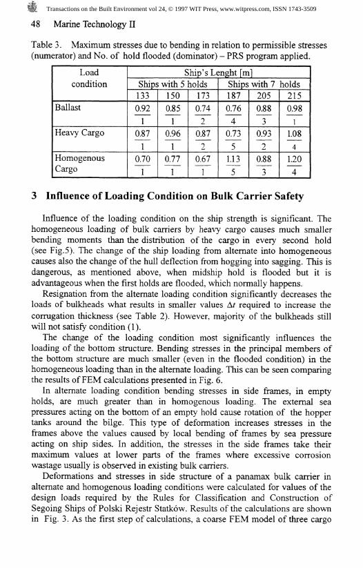
The general strength of existing bulk carriers in flooded conditions dependson length of the ship. This can be seen in Table 3. Flooding of a midship holdof large bulk carrier causes the sagging type of deflection especially inhomogeneous loading (see also Fig. 5). In the sagging condition, the deck iscompressed and this can become dangerous for large bulk carriers since, afterflooding a midship hold, the increase of the deck compression can lead tobuckling of the deck structure.The numbers in the table mean:- the "numerator" is the maximum stress, caused by maximum bendingmoment at still water with one hold flooded and by 0.8 of the design wavebending moment, in relation to the permissible stresses equal to 175k, MPa;k is the material factor for higher tensile steel applied,
- the "dominator" is the number of hold flooded at which the maximumbending stress occurs.
Transactions on the Built Environment vol 24, © 1997 WIT Press, www.witpress.com, ISSN 1743-3509
48 Marine Technology II
Table 3. Maximum stresses due to bending in relation to permissible stresses(numerator) and No. of hold flooded (dominator) - PRS program applied.
Loadcondition
Ballast
Heavy Cargo
HomogenousCargo
Ship's Lenght [m]Ships with 5 holds133
042
1
0.87
1
0.70
1
150
025
1
0.96
1
0.77
1
173
0.74
2
0.87
2
0.67
1
Ships with 7 holds187
076
4
0.73
5
1.13
5
205
0.88
3
0.93
2
0.88ij
215
048
1
1.08
4
1.20
4
3 Influence of Loading Condition on Bulk Carrier Safety
Influence of the loading condition on the ship strength is significant. Thehomogeneous loading of bulk carriers by heavy cargo causes much smallerbending moments than the distribution of the cargo in every second hold(see Fig.5). The change of the ship loading from alternate into homogeneouscauses also the change of the hull deflection from hogging into sagging. This isdangerous, as mentioned above, when midship hold is flooded but it isadvantageous when the first holds are flooded, which normally happens.
Resignation from the alternate loading condition significantly decreases theloads of bulkheads what results in smaller values A/ required to increase thecorrugation thickness (see Table 2). However, majority of the bulkheads stillwill not satisfy condition (1).
The change of the loading condition most significantly influences theloading of the bottom structure. Bending stresses in the principal members ofthe bottom structure are much smaller (even in the flooded condition) in thehomogeneous loading than in the alternate loading. This can be seen comparingthe results of FEM calculations presented in Fig. 6.
In alternate loading condition bending stresses in side frames, in emptyholds, are much greater than in homogenous loading. The external seapressures acting on the bottom of an empty hold cause rotation of the hoppertanks around the bilge. This type of deformation increases stresses in theframes above the values caused by local bending of frames by sea pressureacting on ship sides. In addition, the stresses in the side frames take theirmaximum values at lower parts of the frames where excessive corrosionwastage usually is observed in existing bulk carriers.
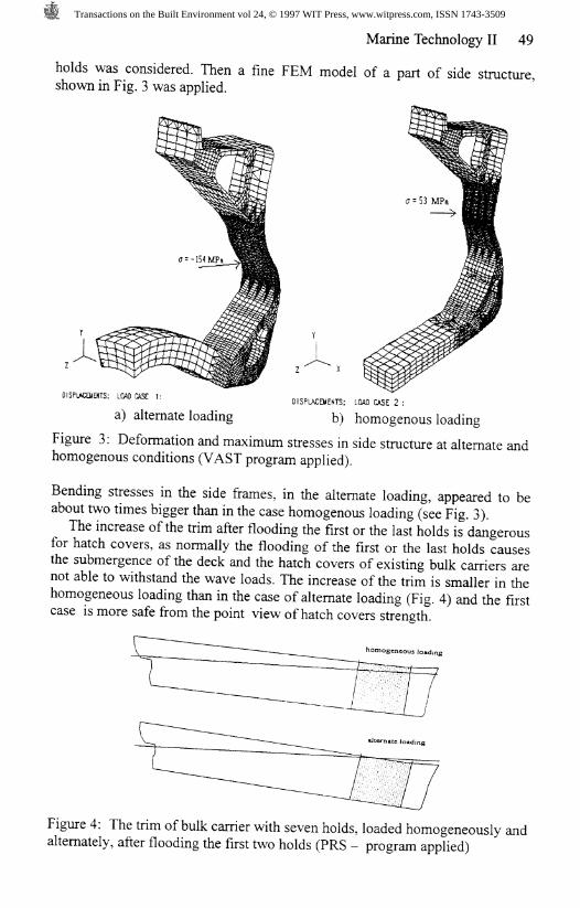
Deformations and stresses in side structure of a panamax bulk carrier inalternate and homogenous loading conditions were calculated for values of thedesign loads required by the Rules for Classification and Construction ofSegoing Ships of Polski Rejestr Statkow. Results of the calculations are shownin Fig. 3. As the first step of calculations, a coarse FEM model of three cargo
Transactions on the Built Environment vol 24, © 1997 WIT Press, www.witpress.com, ISSN 1743-3509
Marine Technology II 49
holds was considered. Then a fine FEM model of a part of side structure,shown in Fig. 3 was applied.
DISPLACEMENTS: LOW) CASE 1: DISPLACEMENTS; LOAD CASE 2 :a) alternate loading b) homogenous loading
Figure 3: Deformation and maximum stresses in side structure at alternate andhomogenous conditions (VAST program applied).
Bending stresses in the side frames, in the alternate loading, appeared to beabout two times bigger than in the case homogenous loading (see Fig. 3).
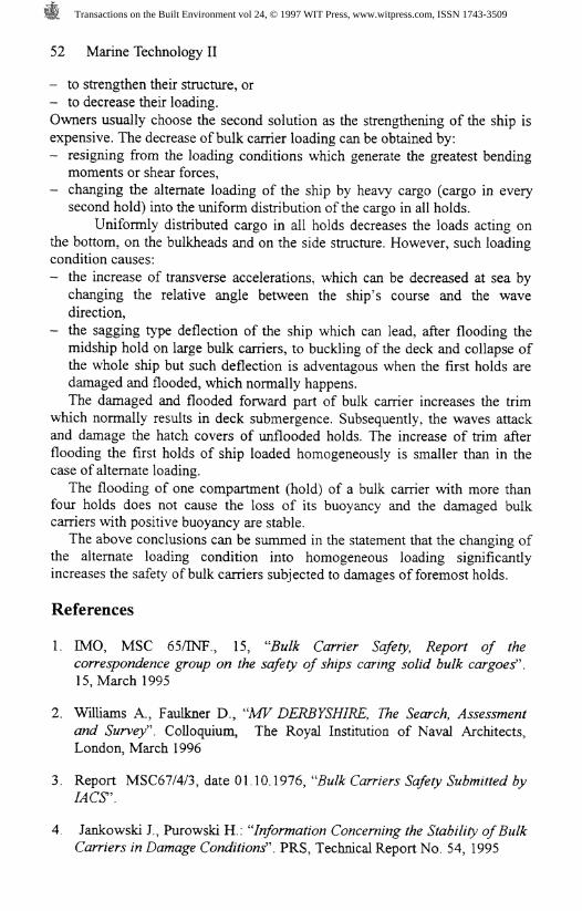
The increase of the trim after flooding the first or the last holds is dangerousfor hatch covers, as normally the flooding of the first or the last holds causesthe submergence of the deck and the hatch covers of existing bulk carriers arenot able to withstand the wave loads. The increase of the trim is smaller in thehomogeneous loading than in the case of alternate loading (Fig. 4) and the firstcase is more safe from the point view of hatch covers strength.
Figure 4: The trim of bulk carrier with seven holds, loaded homogeneously andalternately, after flooding the first two holds (PRS - program applied)
Transactions on the Built Environment vol 24, © 1997 WIT Press, www.witpress.com, ISSN 1743-3509

50 Marine Technology II
Alternate Loading Condition
Homogeneous Loading Condition
*o*v» » A
Loading condition : o = «ir?o c
Homogeneous Loading Condition and Hold 4 Flooded
Figure 5: Still water bending momentsand and shear forces in bulk carrier ofZ,=185 m (seven holds) (PRS programapplied).
«) ALTERNATE LOADING
a - the stresses resulting from bendingof the bottom primary members
/- deflectionFigure 6: Results of the zone strengthanalysis of bulk carrier (£=215 m)(MAESTRO program applied).
Transactions on the Built Environment vol 24, © 1997 WIT Press, www.witpress.com, ISSN 1743-3509

Marine Technology II 51
Heavy cargo is usually loaded in every second hold of a bulk carrier to raisethe centre of mass of the ship because uniformly distributed cargo in all holdsmakes the ship too "stiff " and great transverse accelerations can occur, whichis inconvenient for the crew. To investigate the influence of the change of theloading condition on transverse accelerations (UT\ these accelerations havebeen calculated at the bridge of a bulk carrier of 1=215 m (seven holds), indifferent sea states and different angles between the ship and waves. The seastate is determined by significant wave height #, and by characteristic period Tand relative angle (3 ((3=180° determines the head waves). Results of thecalculations are presented in Table 4. Numbers in the table determine theaverage from 1/10 of the heighest transverse accelerations in given sea states. Itcan be seen from the table that:
1. the change of loading condition from alternate to homogeneous increases thetransverse accelerations at bridge in average by 25%,
2. the change of angle for example from to (3=120° to 150° reduces a% by 60%.
The calculations show that transverse accelerations can be controlled(reduced) by changing the course of the ship in relation to waves.
Table 4. Transverse acceleration at the bridge in different loading condition,in m/s
(#,,n
(2.5, 4.4)(3.5,5.3)(4.5, 6.1)(5.5, 6.9)(6.5, 7.8)(7.5, 8.8)(8.5, 9.8)(9.5, 10.7)(11,11.7)(13,12.8)(15, 143)(17, 16.1)
alternate
P120°
0150.470.941.672.904.55.96.97.98.79.08.66
150°
0.070.160.290.490.871.582.433.163.94.64.984.88
180°
0.00.00.00.00.00.00.00.00.00.00.00.0
homogenous
P120°
0.160.51.12.23.85.66.87.78.49.19.18.6
150°
0.070.170320.591.11.862.53.03.543133.993.67
180°
0.00.00.00.00.00.00.00.00.00.00.00.0
4 Conclusions
Heavy losses of bulk carriers during the last five years resulted in discussionon the minimum safety standards, which should take into account damageconditions (one hold flooded). The strength of existing bulk carriers is notsufficient to withstand the loads resulting from the damage condition and it isnecessary:
Transactions on the Built Environment vol 24, © 1997 WIT Press, www.witpress.com, ISSN 1743-3509
52 Marine Technology II
- to strengthen their structure, or- to decrease their loading.Owners usually choose the second solution as the strengthening of the ship isexpensive. The decrease of bulk carrier loading can be obtained by:- resigning from the loading conditions which generate the greatest bending
moments or shear forces,— changing the alternate loading of the ship by heavy cargo (cargo in every
second hold) into the uniform distribution of the cargo in all holds.Uniformly distributed cargo in all holds decreases the loads acting on
the bottom, on the bulkheads and on the side structure. However, such loadingcondition causes:- the increase of transverse accelerations, which can be decreased at sea by
changing the relative angle between the ship's course and the wavedirection,
- the sagging type deflection of the ship which can lead, after flooding themidship hold on large bulk carriers, to buckling of the deck and collapse ofthe whole ship but such deflection is adventagous when the first holds aredamaged and flooded, which normally happens.The damaged and flooded forward part of bulk carrier increases the trim
which normally results in deck submergence. Subsequently, the waves attackand damage the hatch covers of unflooded holds. The increase of trim afterflooding the first holds of ship loaded homogeneously is smaller than in thecase of alternate loading.
The flooding of one compartment (hold) of a bulk carrier with more thanfour holds does not cause the loss of its buoyancy and the damaged bulkcarriers with positive buoyancy are stable.
The above conclusions can be summed in the statement that the changing ofthe alternate loading condition into homogeneous loading significantlyincreases the safety of bulk carriers subjected to damages of foremost holds.
References
1. IMO, MSC 65/INF., 15, "Bulk Carrier Safety, Report of thecorrespondence group on the safety of ships caring solid bulk cargoes".15, March 1995
2. Williams A., Faulkner D., "MV DERBYSHIRE, The Search, Assessmentand Survey". Colloquium, The Royal Institution of Naval Architects,London, March 1996
3. Report MSC67/4/3, date 01.10.1976, "Bulk Carriers Safety Submitted byA4CT.
4 Jankowski I, Purowski H : "Information Concerning the Stability of BulkCarriers in Damage Conditions". PRS, Technical Report No. 54, 1995
Transactions on the Built Environment vol 24, © 1997 WIT Press, www.witpress.com, ISSN 1743-3509