improving building fabric energy efficiency in hot-humid
TRANSCRIPT

1
Improving Building Fabric Energy Efficiency in Hot-Humid
Climates using Dynamic Insulation
ABSTRACT
New effective technologies and materials that have the potential to reduce energy demand
with excellent energy efficiency and low environmental impact are urgently required in the
Gulf region. Dynamic insulation, which functions by recycling fabric heat loss back to the
building, has been established theoretically and proven in pilot projects. It sets the green, low
carbon benchmark for thermal insulation in buildings.
This paper presents details of the Eco-Villa, its construction, how the performance of the villa
was monitored, and the findings from the initial monitoring phase and the Dynamic
Simulation Model (DSM). The villa was tested in two modes, bypass (static) and dynamic.
The static U value of the external envelop wall was estimated at 0.24W/m2K in bypass mode.
The theoretical dynamic U value changed from 0.24 to 0.05 W/m2K when the ventilation air
flow was varied from 0 to 1litres/s/m2, with a further small reduction occurring when the flow
rate increased beyond 1litres/s/m2. The design ventilation rate for the Eco-Villa was
0.8litres/s/m2, which yielded a theoretical dynamic U value of 0.063W/m
2K compared to a
measured U value of 0.125 W/m2K. The reduction in the fabric conduction gain was found to
be 41% whereas the estimate from the DSM was 38%.
The results demonstrate the fabric energy efficiency improvements that can be achieved
through the use of dynamic insulation. They show that the average air conditioning peak load
demand was reduced in dynamic mode by 25% and that the villa consumed 5.0% less
electrical energy for air conditioning. The results from the DSM suggest the annual cooling
energy consumption would be reduced by 3.8%.
NOMENCLATURE
Az Zone floor area (m2)
C Specific Heat Capacity (J/kg K)
h Overall wall height (m)
P
Q
Power (W)
Heat flux (W/m2)
R Resistance (m2K/W)
T Temperature (K)
U Overall heat transfer coefficient (W/m2K)
v Velocity (m/s)
Va Outdoor airflow rate required per unit area (m3s
-1/m
2)
Vbz Breathing zone outdoor airflow rate (m3s
-1)
Vp Outdoor airflow rate required per person (m3s
-1/person)
x Width (m)
y Height (m)
Zp Zone Population
Greek
a Density (kg/m3)
2
Subscripts
a Air
c Cavity
d Dynamic
i Indoor
o Outdoor
s Static
y Elevation
INTRODUCTION
Rising standards in the face of increasing pollution levels mean that higher volumes of clean,
fresh air are needed in order to improve indoor air quality (IAQ). This gives the Heating,
Ventilation and Air Conditioning (HVAC) engineer a higher thermal load to remove from the
building and raises maintenance issues. This is especially true in very hot, humid climates
such as in the Gulf Region, where outdoor air has to be conditioned to the desired comfort
humidity and temperature before it can be supplied to indoor spaces. Air conditioning at high
ventilation rate requires additional equipment and energy to be used. The cooling process also
very often requires some post-heating of the tempered air before it is supplied to indoor
spaces.
The current rate of energy consumption for air conditioning and the high capital investment
that is required are not sustainable. Neither is a building design methodology that relies on
reduction of fresh ventilation air to reduce cooling energy at the expense of compromised
IAQ. In essence, introduction of fresh ventilation air into buildings affects both energy
consumption and indoor air quality. When space conditioning is necessary, the energy
required to maintain comfortable conditions and acceptable IAQ increases with the rate of
ventilation.
A building that uses an air permeable, insulated external envelope can significantly reduce
energy use for both cooling and heating while at the same time allowing higher than normal
volumes of clean, optionally filtered ventilation air to be introduced to the building at all
times, Elsarrag and Imbabi (2009) and Elsarrag et al. (2006).
This approach is at odds with systematic reductions in infiltration and ventilation rates to
reduce energy consumption that in recent years have led to the development of the air tight,
hermetically sealed building. It is however very much in line with the higher ventilation rate
dictated both by better comfort requirements and by the most recent standards such as
ASHRAE (62-2007), where there is acknowledgement of ventilation rates in modern
buildings to deliver to occupants the benefits of healthy indoors environments.
The aim of this paper is to report the energy efficiency that was achieved through use of
dynamic insulation in the Eco-Villa pilot project.The dual focus of the paper is thus fabric
energy efficiency and HVAC energy use reduction attributed to dynamic insulation. The
paper summarises the monitoring results over a period of 8 weeks, between January 2010 and
March 2010.

3
OVERVIEW OF DYNAMIC INSULATION
Research on dynamic insulation goes back to 1978, attributed to a prototype experimental
building completed in France, Anon (1984). This was followed by a second prototype - with
improved design and more extensive instrumentation - built in 1981 and commissioned in
late 1982, Claridge (1991). Several definitions of dynamic insulation can be found in the
literature; simply stated it is a means of reducing building heat loss without the use of
massive thermal insulation. It is achieved by recycling the heat conducted through the fabric
or reducing the temperature gradient across the wall section by means of a suitable heat
transport fluid - usually air.
Using a proportion of the building envelope as the ventilation source means that the flow
velocity through the intervening media required to deliver the number of fresh air changes per
hour is very low. As a result, it has been shown that both efficient conduction heat recovery
and filtration of the incoming air can take place as a function of air change rate, Taylor and
Imbabi (2000) – i.e., the more ventilation air is drawn in the higher the heat recovery.
A formal classification of generic dynamic insulation system has been reported in the
literature by Arquis and Langlais (1986) and the three types which can be associated with
building applications which are permeodynamic, parietodynamic and thermodynamic
insulation. They reported a theoretical model and an efficiency parameter for evaluation of
dynamic insulation systems as compared to conventional insulation. In the case of
permeodynamic insulation, they describe air flow in a direction opposite to the conduction
heat flow through a permeable porous medium, generally mineral fibre which acts as a heat
exchanger – i.e., the air flow changes the local temperature within the porous medium. The
slope of the temperature profile at the cold side is lower and consequently heat losses are
reduced. For parietodynamic insulation, the fresh air supplied to the building circulates
through an air gap along the wall which is preheated before it enters the building. The
principle of thermodynamic insulation is similar to permeodynamic, counter-flow
configuration, but the air circulates in a closed circuit independent of the ventilation system.
A heat exchanger is required to recover what is gained by the air as it flows through the
porous medium.
Bailly (1986) presented a comprehensive and informative review of dynamic insulation in
general, where such systems were compared to the operation of an air-to-air heat exchanger.
Transient models and experiments were used to evaluate the performance of dynamic
insulation systems during the heating season and energy savings of the order of 7 to 14%
were reported.
Models for heat and mass transfer in dynamic insulation were established in the mid-90s
(Taylor et al, 1996; Taylor and Imbabi, 1997, 2000). Elsarrag et al. (2006) reported the results
from the first field trial of the dynamic insulation in Abu Dhabi. Elsarrag and Imbabi (2009)
investigated the use of dynamic insulation in a building facade for zone local insulation and
ventilation. The savings in energy and CO2 reduction were quantified against existing
standards in the Gulf Region. They showed that dynamic insulation can provide tempered
fresh air, raise energy efficiency and reduce air conditioning energy demand without
compromising IAQ or thermal comfort level.
Figure 1 schematically illustrates the differences between dynamic versus static insulation
wall constructions.

4
(a) Dynamic wall
(b) Static wall (bypass)
Figure 1. Wall construction schematics

5
DESCRIPTION OF THE ECO-VILLA
The Eco-Villa was constructed in United Arab Emirates (UAE) to evaluate the use of
dynamic insulation in the hot climate of the Gulf Region. The villa, a detached family home
on two floors, was built using pre-cast concrete panels.
The external wall construction details are shown in Figure 2. Assemblies of air permeable
dynamic insulation cells were fitted internally over the available wall area and sealed in place
using an independent, self-supporting gypsum board lining system that contained and
protected the cell as shown in Figure 3.
Figure 2. Wall construction layers of the Eco-Villa
9mm wallboard + vapour barrier
25mm formed steel battens
75mm pre-cast concrete cladding
Breather Membrane
95mm dynamic cell (140mm incl cavities)
22.5mm external cavity
50 mm XPS insulation board
75mm pre-cast concrete cladding
22.5mm internal cavity

6
(a) Prior to cladding (b) After cladding
Figure 3. Dynamic insulation applied to external walls.
In operation, ventilation air flows through the rainscreen cladding via an inlet vent into an air
cavity, then through the dynamic insulation cells into an internal air cavity, and thereafter
through the dry wall cladding via an outlet vent or duct. The roof and floor were insulated by
conventional static insulation but internal partitions were left without insulation.
The arrangement that was deployed in the Eco-Villa was such that the external walls of each
floor operated independently – i.e., without the incoming fresh air having to pass through
more than one floor height of dynamic insulation. Inlet ventilation louvers were fitted with
integral sand traps to wall faces and a ring-duct in the ceiling void was used to collect the
incoming air and deliver it to the roof-mounted central air conditioning system.
In order to enable comparative performance to be benchmarked, a bypass duct was installed
at roof level to provide fresh ventilation air when the villa is operated in bypass-mode – i.e.,
with no air flow through the insulated walls The design outdoor airflow required in the
breathing zone of the occupied space was determined according to ASHRAE standard (62-
2007).
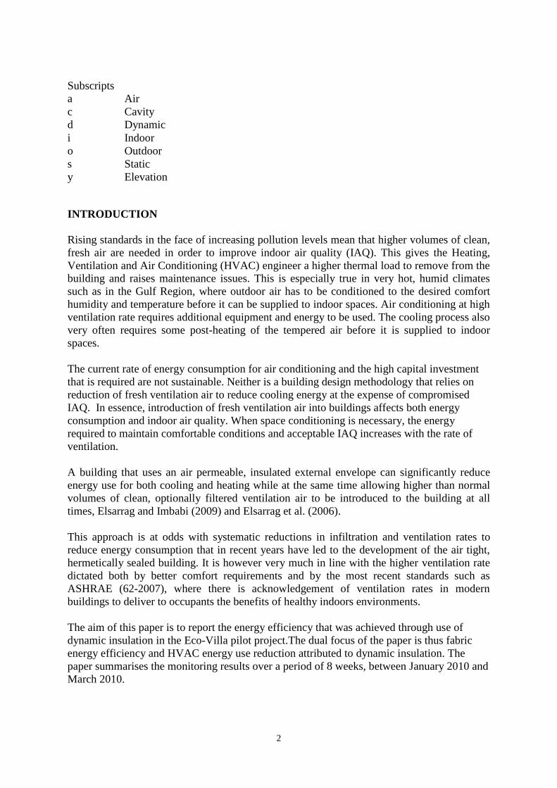
The HVAC schematics in Figure 4, superimposed on the roof and ground floor plans, show
the basic layout of equipment, ducts and sensors (for both temperature and humidity) that
were installed in the villa (W is the wall sensor location, R the room and D the air duct). The
measurements were taken with the villa unoccupied, i.e., lighting and domestic hot water
remained switched off during operation. In addition to measurement points shown in Figure
4, an energy meter was installed.
Direct A/B comparisons of U value and energy consumption in dynamic versus bypass
modes of operation of the villa over a period of 2 month was carried out using a ventilation
rate of 0.0008m3/s (0.8 litres/s) per m
2 of the external wall area.
7
(a) Ground floor

8
(b) Roof
Figure 4. HVAC and sensor layout
THEORETICAL DYNAMIC U VALUE
A theoretical 1-D model of a wall of unit width and height h, comprising an outer rain screen,
external cavity, permeodynamic insulation layer, internal cavity and dry wall lining, as shown
in Figure 5, has been developed. The model combines permeodynamic heat recovery as air
flows through the insulation layer and parietodynamic heat recovery as the same air flows
across the internal cavity to the outlet from the wall. This model, its derivation and the
resulting governing equations will now be summarised.
NN
ROOF Duct
Sensors
D5
D4D3

9
Internal and External Cavities Temperatures:
For external cavity, see Figure 5, the temperature is governed by the fabric conductance and
ventilation conductance playing no part.
ido
o
oi
oy
RRR
R
TT
TT
1 (1)
ido
oiooy
RRR
TTRTT
1
(2)
Where Rd is given in Taylor et al. (1996) as:
aaa
saaad
vC
RvCR
1)exp( (3)
a and Ca are the density and specific heat capacity of air, and Rs the thermal resistance of
dynamic insulation when va = 0.
For internal cavity, see Figure 6, temperature is governed by both fabric conductance and
ventilation conductance.
yR
TTP
i
iy
i
2 (4)
yRR
TTP
do
yo
o
2 (5)
yTTvCP yoaaavent )( 1 (6)
Conservation of energy yields the following equation:
22
1
2
ycaa
yoaaaio
yvxC
yTTvCPPT
(7)
Substituting equations (4) and (5) in (7):
Cy
TA
y
T yy 22
(8)
Where
ido
yodoiaaaiodoi
RRR
TTRRRvCRTRRTA
1
ido
doiaaa
RRR
RRRvCC

10
y 0,
Cy
TA
dy
dT yy 22 (9)
Using the Integrating Factor Method, the solution of Eq (9) yields:
2
*
2 2Cyy
e
FAyT (10)
Where F* is an integration constant (A and C are as previously defined).
The value of this constant can be determined from consideration of the boundary conditions
at the inlet – i.e., at y = 0:
do
iy
i
iy
yoaaaRR
TT
R
TTTTvC
000
22
2
(11)
doiaaaido
doiidoiaaaoy
RRRvCRRR
RRRTRRRvCTT
02 (12)
Substituting the above expression in Eq (10):
A
RRRvCRRR
RRRTRRRvCTATF
doiaaaido
idoidoiaaaoy
)0(2
*
(13)
Thus:
2
2 2Cy
doiaaaido
idoidoiaaao
y
e
ARRRvCRRR
RRRTRRRvCT
AyT
(14)
Heat Flux Equations
The power loss per unit area, Qid, see Figure 6, is given from:
01
yas
dy
dP
R
TT
y
P o
o
yoo (15)
Integration of Eq (15) over the full wall height h yields:
o
yo
dd
o
yo
oR
TTQhQ
R
TThP
1
11
1
(16)

11
The power gain per unit area, Q2d, see Figure 6, is given from:
02
yas
dy
dP
R
TT
y
P i
i
iyi (17)
Integration of Eq (17) over the full wall height h yields:
d
h
iy
i
i hQdyTTR
hP 2
0
2 (18)
2
21*
0 2
*
2 2
Cherf
ChR
F
R
TAdy
e
FAT
hRQ
ii
i
h
Cyi
i
d
(19)
Where erf(z) is the error function.
Dynamic U Values:
The dynamic heat loss coefficient from the wall, U1d, is thus:
ioo
yo
io
dd
TTR
TT
TT
QU
111 (20)
This defines what the author and others (Dalehaug (1993) and Dimoudi et al. (2004)) have
called the dynamic U-value of the wall construction – i.e., the net thermal transmission loss to
ambient.
The corresponding dynamic heat gain coefficient by the wall, U2d, is:
2
21*
22
Cherf
TTCh
F
TT
TA
RTT
QU
ioio
i
iio
dd
(21)
The dynamic heat gain coefficient by the wall, U2d, is the perceived thermal transmission rate
per unit area of dry wall.

12
Figure 5. Model geometry and notation
Figure 6. Energy balance schematics
RESULTS AND DISCUSSION
1. External Wall U values
To obtain the theoretical external wall U value for the Eco-Villa, the physical properties of
the external wall construction shown in Figure 2 were used in the above equations using air
flow rate ranges of 0 to 4litres/s per m2 of external wall area. The dynamic and dry wall U
values calculated from equations (20) and (21) are plotted in Figures 7 and 8 respectively.
It can be seen that at zero flow rate, the bypass mode, the external wall U value is
0.24W/m2K which represents the static U value of the wall. The dynamic U value reduces
from 0.24 to 0.05 W/m2K when the ventilation air flow is varied from 0 to 1litres/s/m
2 and
only slight reduction occurs when the flow rate increases from 1 to 4litres/s/m2, see Figure 7.

13
In contrast, the U value at the dry wall face increases from 0.24 to 3.6W/m2K, see Figure 8.
The tested villa design ventilation rate is 0.8litres/s/m2 which provides a design theoretical
dynamic U value of 0.063W/m2K. The perceived theoretical dry wall U value is 1W/m
2K.
The increase in the static U value at the dry wall side to 1W/m2K at 0.8litres/s/m
2 represents
direct cooling of air in the dry wall cavity space, after it has passed the dynamic insulation.
Figure 7. Theoretical dynamic U value (U1d)
Figure 8. Dry wall perceived dynamic U value (U2d)
0
0.05
0.1
0.15
0.2
0.25
0 0.5 1 1.5 2 2.5 3 3.5 4
U v
alu
e W
/m2 .
K
Litres/s.m2
Design (0.8, 0.063)
0
0.5
1
1.5
2
2.5
3
3.5
4
0 0.5 1 1.5 2 2.5 3 3.5 4
U v
alu
e W
/m2.K
Litres/s.m2
Design (0.8, 1.0)

14
To verify the actual operating U value for the Eco-Villa for both dynamic mode and static
mode the wall conduction load was determined. The energy consumed by the villa, measured
using the energy meter, in the absence of internal gains (the villa was not occupied), is only
of the air conditioning load and includes fabric, solar and ventilation loads. The data from
dynamic versus static modes of operation was obtained from sequential runs of 1 week’s
duration in each case. The results that are presented in this paper were taken from two
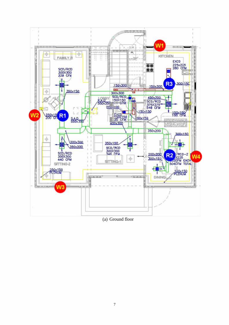
consecutive weeks that have comparable indoor and outdoor conditions. Figures 9 and 10
show the measured indoor and outdoor air temperatures for the two modes over these two
consecutive weeks. The indoor set point was kept constant at 23oC for both static and
dynamic cases.
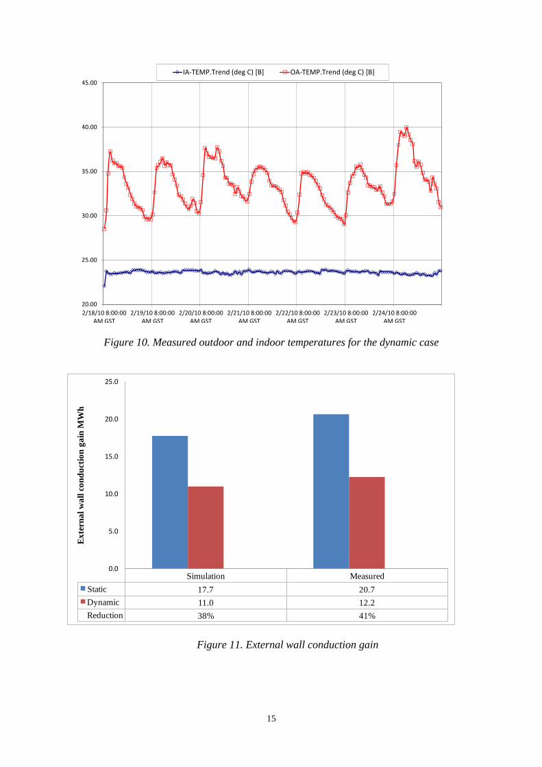
A Dynamic Simulation Model (DSM) for the Eco-Villa was developed using Integrated
Environmental Solutions software (IES v6.3) for both the static mode and dynamic mode to
obtain the external wall conduction gain. The DSM was used to allow the theoretical
breakdown of annual energy demand for both static and dynamic modes to be estimated.
Figure 11 shows a 38% reduction in the conduction heat transfer within the measure period
using DSM where the actual data has shown 41% reduction within the tested period. There is
thus reasonable agreement in the percentage reduction between the DSM and measured
values.
Figure 12 tracks a like-for-like observed dynamic U value reduction of 48% against the static
baseline reference calculated from the theoretical model at 0.8litres/s/m2, corresponding to a
static U-value of 0.125 W/m2K. The theoretical model shows this to be equivalent to a 74%
reduction from the static case compared to the design theoretical value of 0.063 W/m2K at
0.8litres/s/m2.
Figure 9. Measured outdoor and indoor temperatures for the bypass baseline case
20.00
25.00
30.00
35.00
40.00
45.00
2/25/10 8:00:00AM GST
2/26/10 8:00:00AM GST
2/27/10 8:00:00AM GST
2/28/10 8:00:00AM GST
3/1/10 8:00:00AM GST
3/2/10 8:00:00AM GST
3/3/10 8:00:00AM GST
IA-TEMP.Trend (deg C) [A] OA-TEMP.Trend (deg C) [A]
15
Figure 10. Measured outdoor and indoor temperatures for the dynamic case
Figure 11. External wall conduction gain
20.00
25.00
30.00
35.00
40.00
45.00
2/18/10 8:00:00AM GST
2/19/10 8:00:00AM GST
2/20/10 8:00:00AM GST
2/21/10 8:00:00AM GST
2/22/10 8:00:00AM GST
2/23/10 8:00:00AM GST
2/24/10 8:00:00AM GST
IA-TEMP.Trend (deg C) [B] OA-TEMP.Trend (deg C) [B]
Simulation Measured
Static 17.7 20.7
Dynamic 11.0 12.2
Reduction 38% 41%
0.0
5.0
10.0
15.0
20.0
25.0
Ex
tern
al
wa
ll c
on
du
ctio
n g
ain
MW
h

16
Figure 12. Measured versus theoretical dynamic U values
This is an excellent result that also shows there is room for improvement. The theoretical
model, for example, does not include allowance for the effects of solar gain or latent heat
effects, both of which can be significant in a hot humid climate. As a consequence, the rate of
heat loss will be higher than otherwise predicted.
Another factor is air flow uniformity across the active wall area. Dynamic insulation is
tolerant of small variations in air flow, with gains in heat recovery efficiency in high flow
areas compensating for reductions in areas of low flow, but large variations will ultimately
degrade performance. This is a system-level issue and an engineering solution is required.
The DSM predicts an annual reduction of 44% in external wall gain in dynamic mode
compared to the bypass mode as shown in Figure 13, which is promising.
(a) (b)
Figure 13. External Wall Conduction Gain a) Monthly; b) Annual
-0.2
-0.1
0
0.1
0.2
0.3
0.4
0.5
0.6
0.7
0.8
Jan 01-31 Feb 01-28 Mar 01-31 Apr 01-30 May 01-31 Jun 01-30 Jul 01-31 Aug 01-31 Sep 01-30 Oct 01-31 Nov 01-30 Dec 01-31
Monthly External Wall Gain, MWh
Static
Dynamic
Static Dynamic
Total 4.4 2.5
Reduction% 44%
0
0.5
1
1.5
2
2.5
3
3.5
4
4.5
5
Annual External Wall Gain, MWh
Reduction achieved
Theoretical Model

17
2. Energy Consumption
In order to enable direct A/B comparisons to be made between the measured values in
dynamic and bypass modes, the measured air conditioning load values have been weather
corrected.The energy consumption in both cases was thus normalised against the temperature
difference between the indoor and outdoor environments. The weather corrected A/C energy
demand is plotted for the baseline and dynamic cases in Figures 14 and 15. The results show
that the average air conditioning peak load demand is reduced in the dynamic mode by 25%.
In dynamic mode the villa used 5.0% less electrical energy for air conditioning kWh/K - see
Figure16. Figure 17 compares the predicted monthly and annual energy consumptions from
the DSM. As shown, the annual cooling energy consumption is reduced by 3.8%.
Figure 14. The weather corrected A/C energy demand for the bypass baseline case
0.10
0.20
0.30
0.40
0.50
0.60
2/25/10 8:00:00
AM GST
2/26/10 8:00:00
AM GST
2/27/10 8:00:00
AM GST
2/28/10 8:00:00
AM GST
3/1/10 8:00:00
AM GST
3/2/10 8:00:00
AM GST
3/3/10 8:00:00
AM GST
KW per deg DT [A]

18
Figure 15. The weather corrected A/C energy demand for the dynamic case
Figure 16. A to B comparison of the A/C normalised energy consumption
0.10
0.20
0.30
0.40
0.50
0.60
2/18/10 8:00:00
AM GST
2/19/10 8:00:00
AM GST
2/20/10 8:00:00
AM GST
2/21/10 8:00:00
AM GST
2/22/10 8:00:00
AM GST
2/23/10 8:00:00
AM GST
2/24/10 8:00:00
AM GST
KW per deg DT [B]
25/02 to 4/03 bypass 18/02 to 25/02 dynamic
Energy Consumption kWh 50.08 47.57
Reduction 5%
0.00
10.00
20.00
30.00
40.00
50.00
Ene
rgy
Co
nsu
mp
tio
n k
Wh
/K
Comparison of bypass vs dynamic

19
(a) (b)
Figure 17. Cooling Energy Consumption a) Monthly; b) Annual
CONCLUSIONS
It is important to note that the dynamic insulation product used in the project was originally
designed for the temperate climates of Northern Europe. In such climates, high solar gain,
humidity and latent heat removal are different to those of the hot and humid Gulf Region.
The use of dynamic insulation in the façade leads to the creation of a dynamic building
system that yields substantial indirect gains in the way that the air conditioning system
operates. The theoretical U value of the wall, at zero flow rate, was found to be 0.24W/m2K
and reduced dramatically to 0.05 W/m2K when the ventilation air flow varied from 0 to
1litres/s/m2. The theoretical dynamic U value at design ventilation rate of 0.8litres/s is
0.063W/m2K compared to a measured U value of 0.125 W/m
2K.The reduction in the fabric
conduction gain was found to be 41% whereas the DSM showed 38%. The results showed
that the villa consumed 5.0% less electrical energy for air conditioning. The DSM predicted
that the annual cooling energy consumption from will be reduced by 3.8%. Extra attention is
clearly required to address latent heat gain and loss issues in the hot-humid climate of the
UAE.
The use of dynamic insulation offers exceptionally low U-value thermal insulation but its
effect does not end there. Isolating solar gain and related effects at the product and system
levels is necessary and will go a long way to improving the overall performance of buildings
in hot, sunny climates. In addition, the extract air from the conditioned space (e.g. toilets,
kitchens, etc.) has a temperature normally between 27 and 30oC which means it could be used
as a cooling source for the package air cooled condenser unit to improve the performance.
The Eco-Villa project has established the validity of using dynamic insulation in hot-humid
climates. It has provided valuable insights into the strengths and weaknesses of the approach
to dynamic insulation that was used. This has led to the development of a new class of
dynamic insulation product optimised for the hot-humid climate of the Gulf Region. The
product needs to be tested and its performance validated in further trials, involving different
building types, in aid of roll out and wider use.
0
1
2
3
4
5
6
7
8
Jan 01-31 Feb 01-28 Mar 01-31 Apr 01-30 May 01-31 Jun 01-30 Jul 01-31 Aug 01-31 Sep 01-30 Oct 01-31 Nov 01-30 Dec 01-31
Monthly Cooling Energy Consumption, MWh
static wall.aps
dyn wall.aps
static wall.aps dyn wall.aps
Total 53 51
Reduction% 3.8%
0
10
20
30
40
50
60
Annual Cooling Energy Consumption, MWh

20
REFERENCES
Anon., "Dynamic Insulation: the Next Step?” Australian Refrigeration, Air Conditioning and
Heating, November, pp.47, 1984.
Arquis E. and Langlais C., "What Scope for 'Dynamic Insulation?" Batiment International
Building Research and Practice, vol. 19, pp. 84-93, 1986.
Bailly N.R., "Dynamic Insulation Systems and Energy Conservation in Buildings" ASHRAE
Transactions, vol. 93, part 1, pp. 447-468, 1987.
Claridge D.E., “The Measured Energy Impact of Air Leakage on Frame Wall Systems” Final
Report, DOE, US, 1991.
Dalehaug A, Dynamic insulation in walls. Research report No 53, ISSN 0915-9215,
Hokkaido prefectural cold region housing and urban research institute, Japan, 1993.
Dimoudi A, A. Androutsopoulos, S. Lykoudis, Experimental work on a linked dynamic and
ventilated wall component, Energy and Buildings 36, p443– 453, 2004.
Elsarrag E., M. Aboulnaga, A. Peacock and M. S. Imbabi, Dynamic insulation for energy
conservation and improved indoor air quality in hot humid climates, Invited keynote paper,
ASHRAE 5th Chapter Regional Conference (CRC), 01 – 03 November, Dubai, UAE, 2006.
Elsarrag E. and Imbabi M. Evaluation of dynamic insulation for zone ventilation and air
conditioning in the gulf region, ASHRAE Symposium on Sustainability and Green Buildings;
Kuwait, October 5, 2009.
Imbabi M S, Modular breathing panels for energy efficient, healthy building construction,
Renewable Energy, Vol. 31, Issue 5, p 729-738, 2006.
Price L, S de la Rue de Can, J Sinton, E Worrell, Z Nan, J Sathaye and M Levine, Sectoral
trends in global energy use and greenhouse gas emissions, Lawrence Berkley Laboratory,
LBNL-56144, 2006.
Taylor, B J and M S Imbabi, Environmental design using dynamic insulation, ASHRAE
Transactions, 106(1), p15-28, 2000
Taylor, B J, D A Cawthorne and M S Imbabi, Analytical investigation of the steady-state
behavior of dynamic and diffusive building envelopes, Building and Environment, Vol.31(6),
p519-525, 1996.
Taylor B J, and M S Imbabi, The effect of air film thermal resistance on the behaviour of
dynamic insulation, Building &Environment, Vol. 32(5), p397-404, 1997.
Taylor B J and M S Imbabi, Environmental design using dynamic insulation, ASHRAE
Transactions, Vol. 106(1), p15-28, 2000.