improvements and updates in the new m&s 16 suite from ... · improvements and updates in the...
TRANSCRIPT
1
Improvements and Updates in the new M&S 16 Suite from PresagisFebruary 2017
“Make it Real” – it’s more than a slogan, it’s what drives us.
We understand that simulation and training is about the real world.
And that our customers live in the real world: They have real world budget constraints, They work with real-world challenges of standards, The real world of technical constraints of hardware and software platforms they need to build solutions for.
We built our suite of tools to provide for all of our users’ simulation and training needs.
With our products: Create: simulation-ready content: 3D entities , vehicles, roads and buildings, to terrain databases Visualize this content in a high-fidelity, frame accurate out the window view
2

Visualize beyond what the naked eye sees using sensors Simulate all forms of platforms in all forms of scenarios from training to new systems design.
2

We’re happy to announce that all tools in our suite now support Windows 10.
For many of our customers this is a big deal.
For many reasons, quality and security being two of them, Windows 10 has been well received by the industry and is rapidly getting adopted.
3

And while we’re talking about Suite-wide improvements, you will be happy to hear that our products now support 4K Screens.
They are now ubiquitous on most new systems.
The Graphical User Interfaces of all our products have been refreshed and even re-designed in some cases to take advantage of these new resolution screens
4
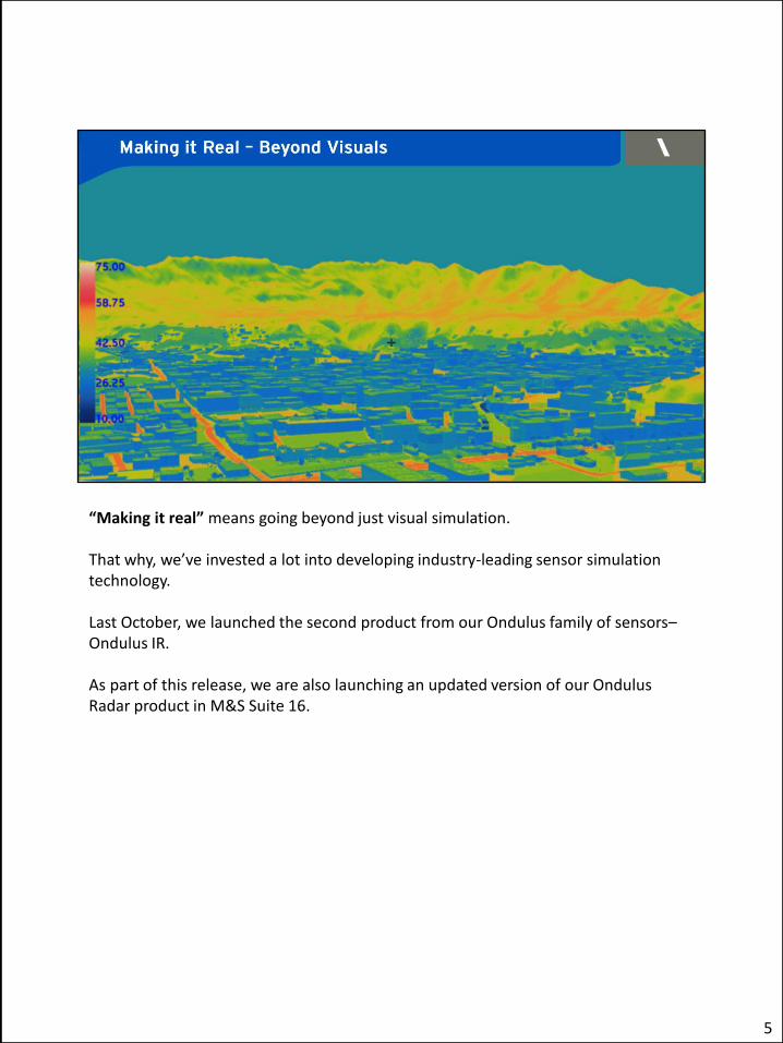
“Making it real” means going beyond just visual simulation.
That why, we’ve invested a lot into developing industry-leading sensor simulation technology.
Last October, we launched the second product from our Ondulus family of sensors– Ondulus IR.
As part of this release, we are also launching an updated version of our Ondulus Radar product in M&S Suite 16.
5
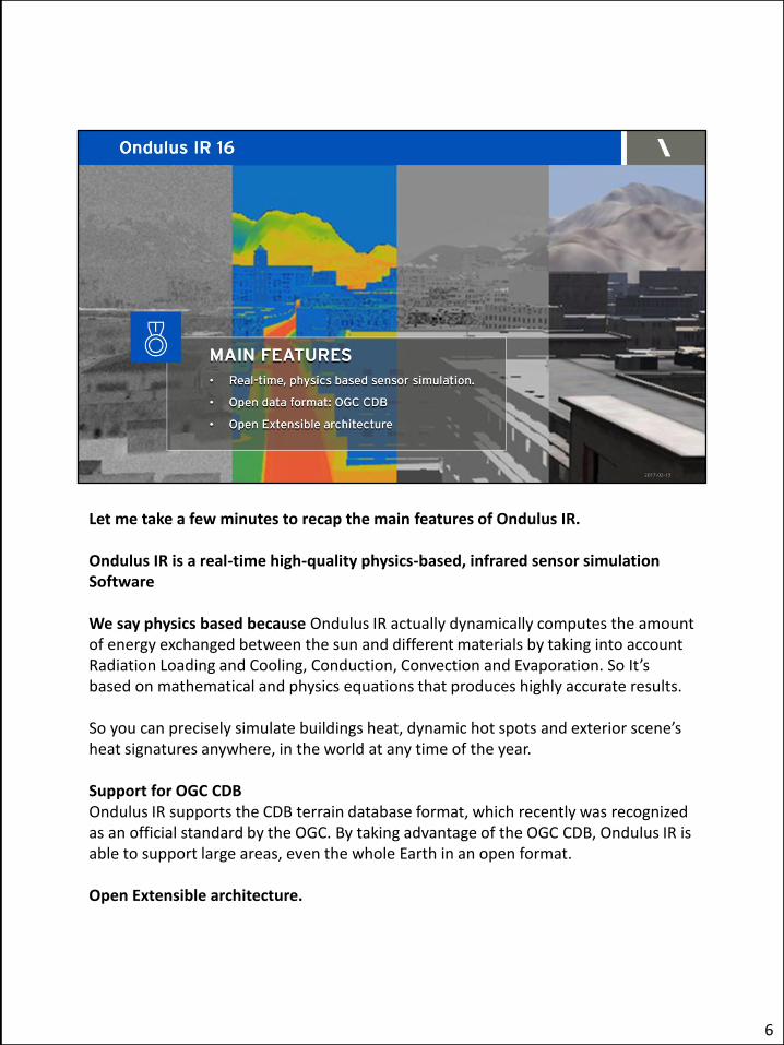
Let me take a few minutes to recap the main features of Ondulus IR.
Ondulus IR is a real-time high-quality physics-based, infrared sensor simulation Software
We say physics based because Ondulus IR actually dynamically computes the amount of energy exchanged between the sun and different materials by taking into account Radiation Loading and Cooling, Conduction, Convection and Evaporation. So It’s based on mathematical and physics equations that produces highly accurate results.
So you can precisely simulate buildings heat, dynamic hot spots and exterior scene’s heat signatures anywhere, in the world at any time of the year.
Support for OGC CDB Ondulus IR supports the CDB terrain database format, which recently was recognized as an official standard by the OGC. By taking advantage of the OGC CDB, Ondulus IR is able to support large areas, even the whole Earth in an open format.
Open Extensible architecture.
6

like our other M&S products, Ondulus IR offers an open and modular architecture; It comes with a C++ API that gives to the users the ability to control and extend it Runs on Linux – Windows (64Bit).
It is developed in Canada and is Non-ITAR.
6
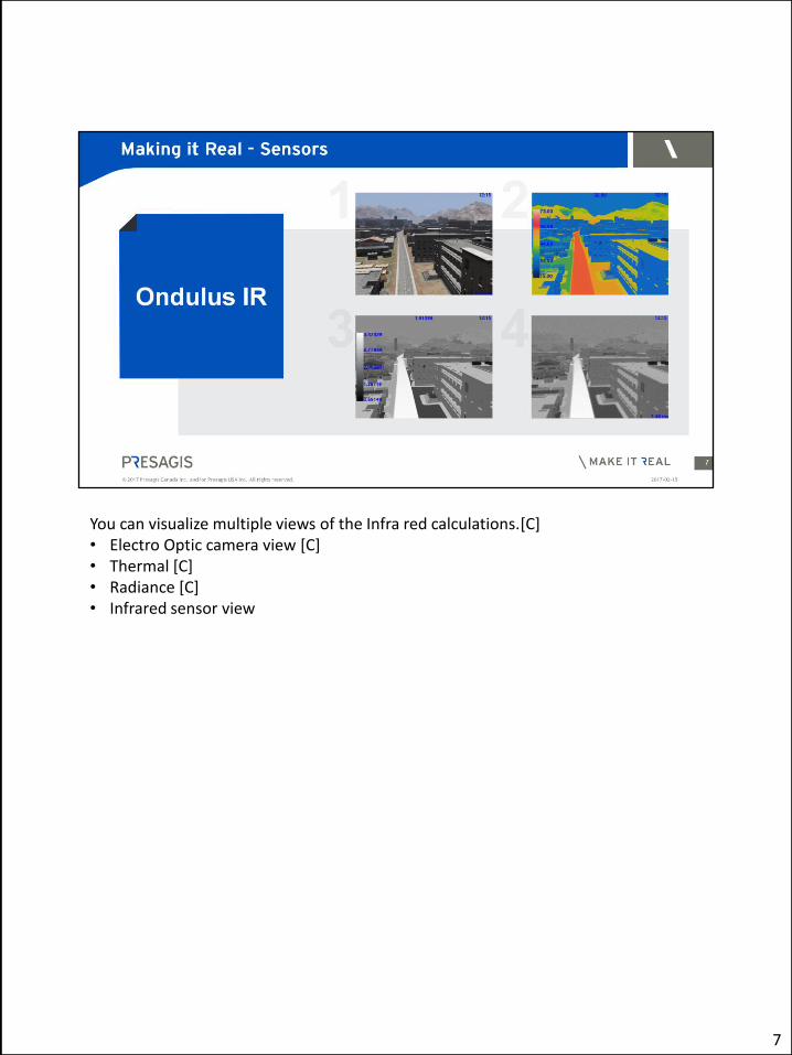
You can visualize multiple views of the Infra red calculations.[C] • Electro Optic camera view [C]• Thermal [C]• Radiance [C]• Infrared sensor view
7
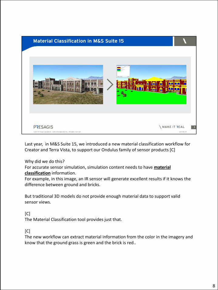
Last year, in M&S Suite 15, we introduced a new material classification workflow for Creator and Terra Vista, to support our Ondulus family of sensor products [C] Why did we do this? For accurate sensor simulation, simulation content needs to have material classification information. For example, in this image, an IR sensor will generate excellent results if it knows the difference between ground and bricks. But traditional 3D models do not provide enough material data to support valid sensor views. [C] The Material Classification tool provides just that. [C] The new workflow can extract material information from the color in the imagery and know that the ground grass is green and the brick is red..
8

8

Continuing the work that we started in M&S Suite 15, we have expanded support for sensors in M&S Suite 16 MAIN FEATURES • Hot Spot Creation Workflow • Roof Clutter in Building Wizard • FBX Import
9
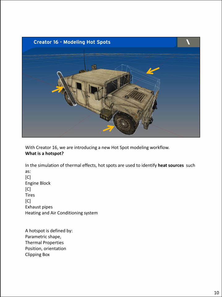
With Creator 16, we are introducing a new Hot Spot modeling workflow. What is a hotspot? In the simulation of thermal effects, hot spots are used to identify heat sources such as: [C] Engine Block [C] Tires [C] Exhaust pipes Heating and Air Conditioning system A hotspot is defined by: Parametric shape, Thermal Properties Position, orientation Clipping Box
10
Hot Spots are uses in cases when heat sources identification is required in simulation scenario, which is of often the case with IR sensors. For example, IR sensors can detect that a vehicle was used recently by the heat signature of the engine block or exhaust pipe. We have integrated Creator and Ondulus IR In Creator, there is a new “Create Hot Spot” tool, that is integrated with existing tools - Maneuver, Duplicate, Etc. This will be easy to use to anyone familiar with Creator. With this workflow, you can model your hot spots in Creator and then save them as part of an Open Flight file. To enable this, we have added Hotspot primitive as the OpenFlight File standard. This means that, using Creator, you can model a complete OpenFlight model, with materials classification and hotspots and then reuse in different simulation scenarios without needing to retouch. You model once and re-use multiple times. Ondulus IR will now be able to read in a fully instrumented 3D assets with Hotspots pre-modeled without the need to edit the content.
10

You can see here the final result in the Ondulus IR sensor view (white hot) • Engine block • Tires • Tail pipe
11
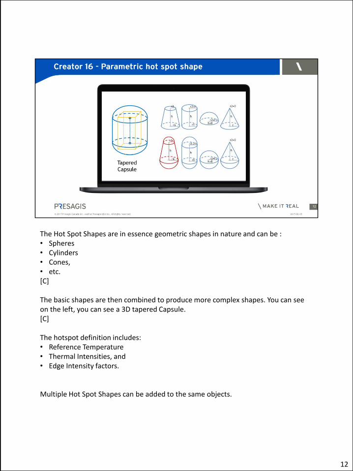
The Hot Spot Shapes are in essence geometric shapes in nature and can be : • Spheres • Cylinders • Cones, • etc. [C] The basic shapes are then combined to produce more complex shapes. You can see on the left, you can see a 3D tapered Capsule. [C] The hotspot definition includes: • Reference Temperature • Thermal Intensities, and • Edge Intensity factors. Multiple Hot Spot Shapes can be added to the same objects.
12
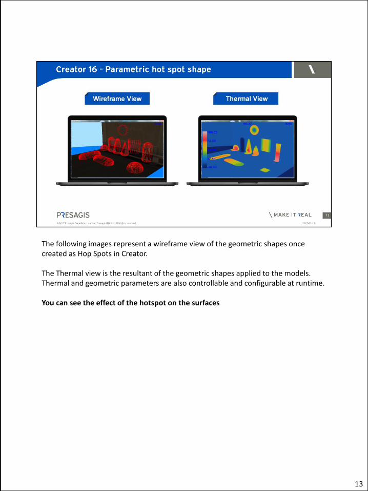
The following images represent a wireframe view of the geometric shapes once created as Hop Spots in Creator.
The Thermal view is the resultant of the geometric shapes applied to the models. Thermal and geometric parameters are also controllable and configurable at runtime.
You can see the effect of the hotspot on the surfaces
13
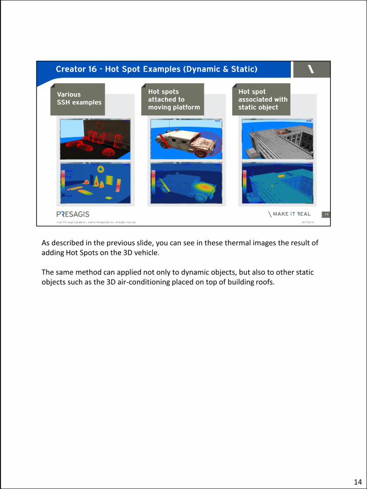
As described in the previous slide, you can see in these thermal images the result of adding Hot Spots on the 3D vehicle. The same method can applied not only to dynamic objects, but also to other static objects such as the 3D air-conditioning placed on top of building roofs.
14

Speaking of roofs. roof clutter items are important cues for pilots. They help identify the type of buildings from the air. Creator 16, we designed new functionality into the building wizard enabling the procedural modeling of Roof Clutter based on a set of rules • Coverage • Model • Orientation/Rotation • Location • External Files This is a relatively effortless way to add visual complexity in your scenes.
15
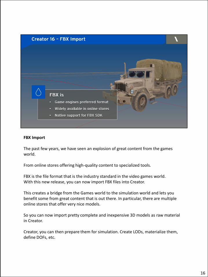
FBX Import
The past few years, we have seen an explosion of great content from the games world.
From online stores offering high-quality content to specialized tools.
FBX is the file format that is the industry standard in the video games world. With this new release, you can now import FBX files into Creator.
This creates a bridge from the Games world to the simulation world and lets you benefit some from great content that is out there. In particular, there are multiple online stores that offer very nice models.
So you can now import pretty complete and inexpensive 3D models as raw material in Creator.
Creator, you can then prepare them for simulation. Create LODs, materialize them, define DOFs, etc.
16

FBX Supports other formats such as : Collada, DXF, .3ds, obj
16

Concerning Terra Vista this latest release is introducing the following MAIN FEATURES: • APT Rule Editor Previewer • Roof Clutter for Wizard Buildings • Updated Output Compilers
17
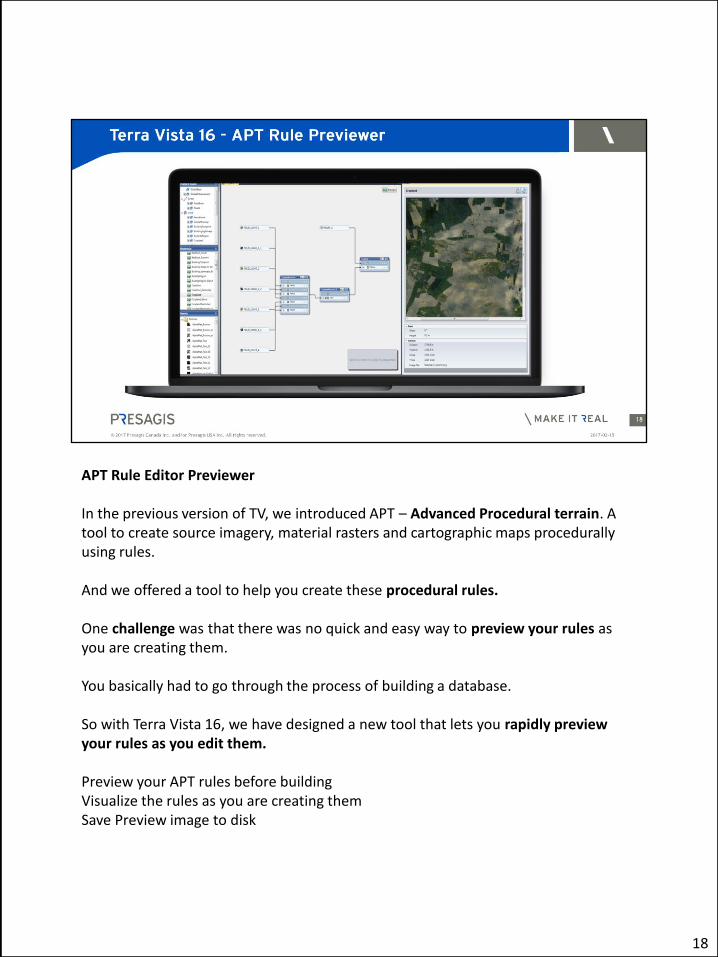
APT Rule Editor Previewer In the previous version of TV, we introduced APT – Advanced Procedural terrain. A tool to create source imagery, material rasters and cartographic maps procedurally using rules. And we offered a tool to help you create these procedural rules. One challenge was that there was no quick and easy way to preview your rules as you are creating them. You basically had to go through the process of building a database. So with Terra Vista 16, we have designed a new tool that lets you rapidly preview your rules as you edit them. Preview your APT rules before building Visualize the rules as you are creating them Save Preview image to disk
18

Use your own elevation file or use preset shapes.
18
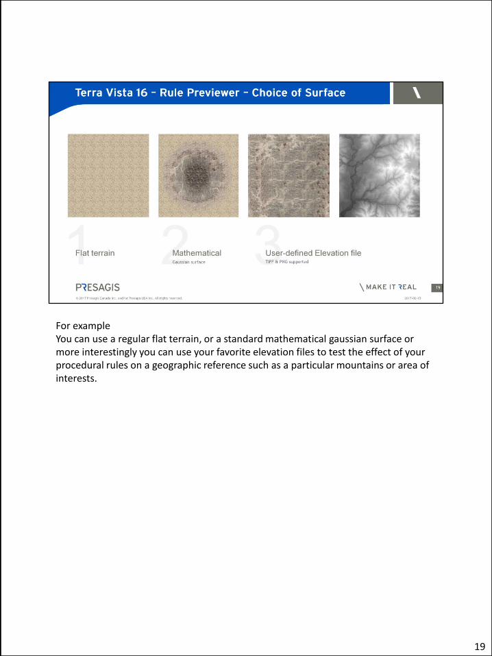
For example You can use a regular flat terrain, or a standard mathematical gaussian surface or more interestingly you can use your favorite elevation files to test the effect of your procedural rules on a geographic reference such as a particular mountains or area of interests.
19

We have shown you how you can use Creator to create roof clutter in the building wizard. You can also create roof clutter in Terra Vista using these rules, in Building Wizard buildings. You can add heating and air conditioner units, antennas on top of buildings • Building Wizard Buildings • Random positions – • Can control the density, the placement seed in Creator Procedural placement of Roof Clutter based on a set of rules • Coverage • Model • Orientation/Rotation • Location • External Files
20
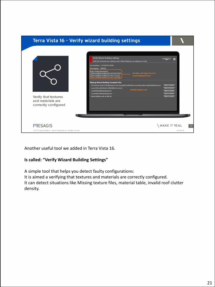
Another useful tool we added in Terra Vista 16. Is called: “Verify Wizard Building Settings” A simple tool that helps you detect faulty configurations: It is aimed a verifying that textures and materials are correctly configured. It can detect situations like Missing texture files, material table, invalid roof clutter density.
21
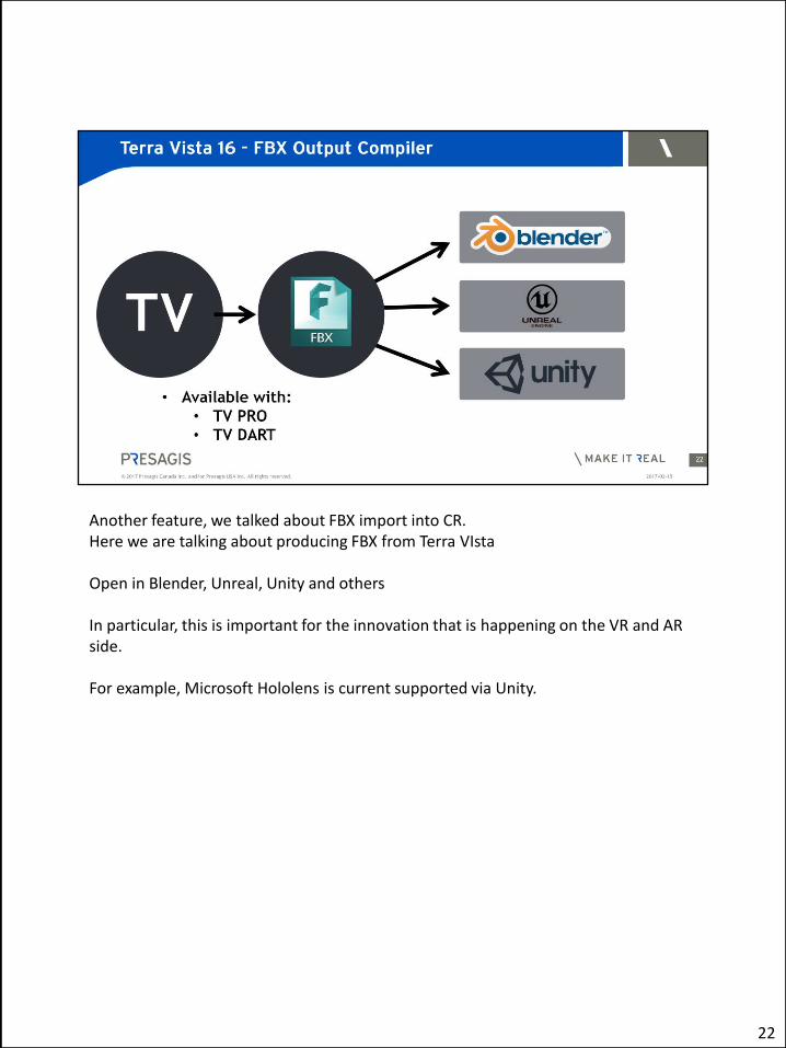
Another feature, we talked about FBX import into CR. Here we are talking about producing FBX from Terra VIsta Open in Blender, Unreal, Unity and others In particular, this is important for the innovation that is happening on the VR and AR side. For example, Microsoft Hololens is current supported via Unity.
22

I mentioned that standards are important to us. In this release we have put a lot of effort into supporting interoperability standards.
• VBS Improvements • sub-meter imagery resolution
• OTF – OneSAF Terrain Format
• JCATS (ver. 12.0, 12.3, 13.0)
23

In Vega Prime We have • Improved Night Scenes • Improved Performance
We are now supporting: • HLA Evolved
And have updated to the latest SDK version of : • Oculus Rift
24

Night Scenes Adaptive Lighting with CDB One issue that we were facing in previous version . You can see in the screen that each tree had their own lighting and which had no affect on its surroundings.
25

Example: trees. [C] Street light is illuminating this area [C] This tree should be lighter than [C] This tree New feature in Vega Prime 16 GT Features can be lit based on their position When a CDB Database includes both Terrain Light Maps and Model Light Maps, the light map intensity of each GT feature is scaled based on the Terrain Light Map.
26
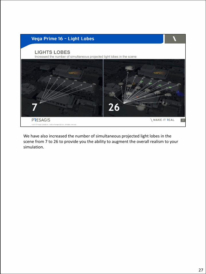
We have also increased the number of simultaneous projected light lobes in the scene from 7 to 26 to provide you the ability to augment the overall realism to your simulation.
27
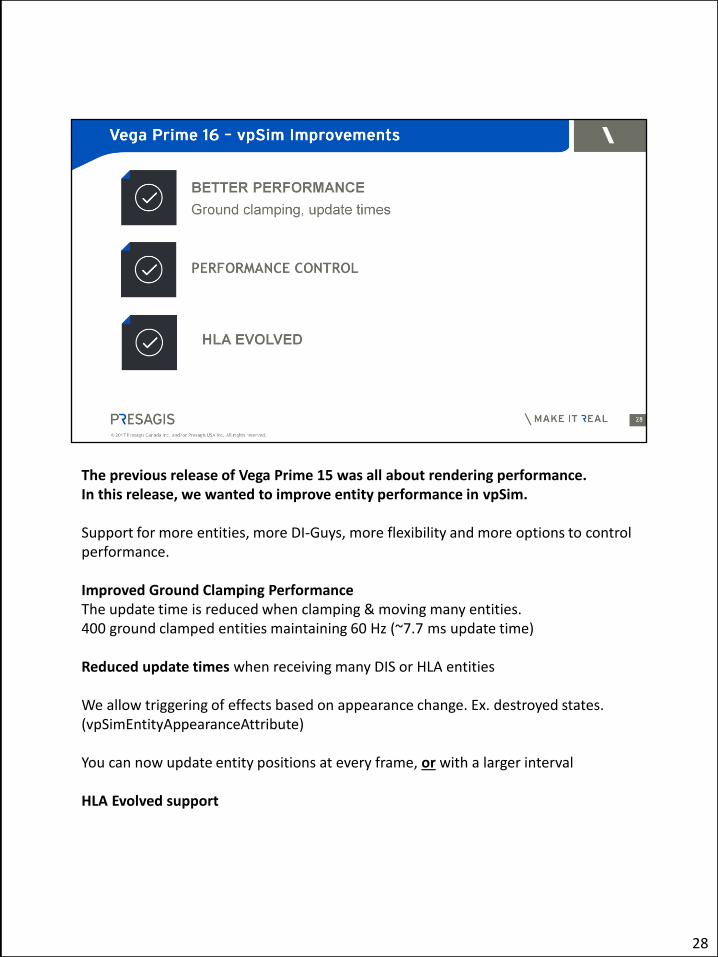
The previous release of Vega Prime 15 was all about rendering performance. In this release, we wanted to improve entity performance in vpSim. Support for more entities, more DI-Guys, more flexibility and more options to control performance. Improved Ground Clamping Performance The update time is reduced when clamping & moving many entities. 400 ground clamped entities maintaining 60 Hz (~7.7 ms update time) Reduced update times when receiving many DIS or HLA entities We allow triggering of effects based on appearance change. Ex. destroyed states. (vpSimEntityAppearanceAttribute) You can now update entity positions at every frame, or with a larger interval HLA Evolved support
28

DI-Guy Performance Improvements Those are aimed at minimizing the update times by: • Improved culling. • Optimization for off-screen DI-Guys
• Those characters are calculated more efficiently • 60Hz with >400 DI-Guy scenario – we’re very happy with that result
29

SIGNIFICANT PIXEL SIZE ADJUSTMENT Allows control of detail to manage rendering performance based on your resolution and field of view. ADAPTIVE VSYNC SUPPORT ADDED TO LYNX PRIME Allows late swaps to occur without synchronization to the video frame Reduces jitter on late frames UPDATED OCULUS SAMPLE use the new Oculus Rift SDK V1
30
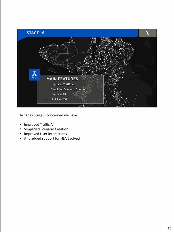
As far as Stage is concerned we have : • Improved Traffic AI • Simplified Scenario Creation • Improved User Interactions • And added support for HLA Evolved
31

We have improved the Wander behavior. Ground traffic navigation behavior of vehicles and humans are much more realistic. Unfortunately, we cannot show it here, but I encourage you to watch the video that we will be posting . The improved behavior also consumes less computer resources in runtime. Also, Ground Navigation debug rendering over the Tactical Map is improved in terms of performance. Finally - Various improvements in the AI editor such as : • Drawing in the Visualization tab is now faster. • It is now possible to open an ACX file by dragging and dropping it on top of the
AI.DE window. • An item "Play As Fast As Possible" was added to the Playback Settings dialog box
to allow playing a scene without sleeping between iterations.
32

• The Tools menu has a new menu item, Locate Cell/Polygon, to quickly find thegiven cell of a NavContext or polygon of a physical object.
• The Stats monitor layout was improved.
32
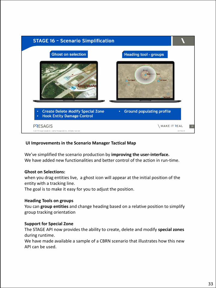
UI Improvements in the Scenario Manager Tactical Map We’ve simplified the scenario production by improving the user-interface. We have added new functionalities and better control of the action in run-time. Ghost on Selections: when you drag entities live, a ghost icon will appear at the initial position of the entity with a tracking line. The goal is to make it easy for you to adjust the position. Heading Tools on groups You can group entities and change heading based on a relative position to simplify group tracking orientation Support for Special Zone The STAGE API now provides the ability to create, delete and modify special zones during runtime. We have made available a sample of a CBRN scenario that illustrates how this new API can be used.
33

Hook Entity Damage Control An entity damage level can now be controlled through the runtime hook window Ground populating Ground populating settings can now be saved in profiles that can be reused at a later time in other scenario
33

Updated all our simulation products to support HLA Evolved Keeping up with industry standards Benefits Modular FOMS – more flexibility Most of the time, it means that systems can connect to any federation out of the box without the need to propagate the FOM extensions across all federates. Based on HLA Evolved and the PRESAGIS_FOM16, M&S Suite Suite 16 products are RPRFOM 2.0 compliant and can interoperate with any other RPRFOM 2.0 federate. In addition, M&S Suite Suite 16 products can interoperate with federates that are compatible with the DI Guy 13.1 FOM extension. The minimal requirement for a federate to interoperate with Presagis products out of the box is RPRFOM 2.0 support. Other FOMs can be supported with user customization assisted by the Pitch Developer Studio code generation application.
34

Other Miscellaneous improvements : • New API for improved control from external applications
• IMPROVED M&S SUITE INTEROPERABILITY • Better interoperability between Flightsim, Helisim, VP and Creator.
35
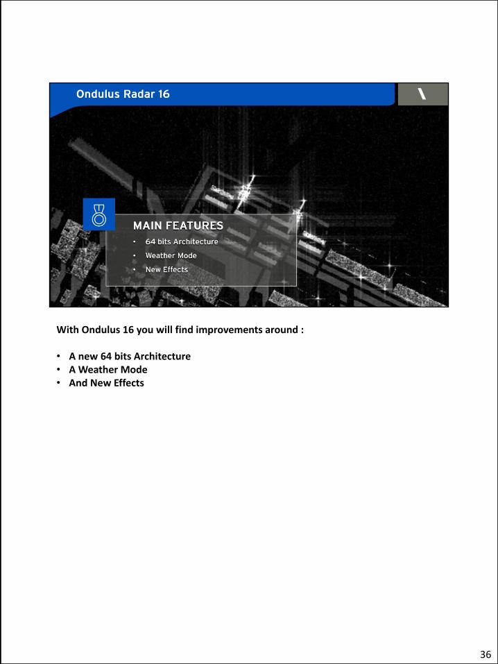
With Ondulus 16 you will find improvements around : • A new 64 bits Architecture • A Weather Mode • And New Effects
36
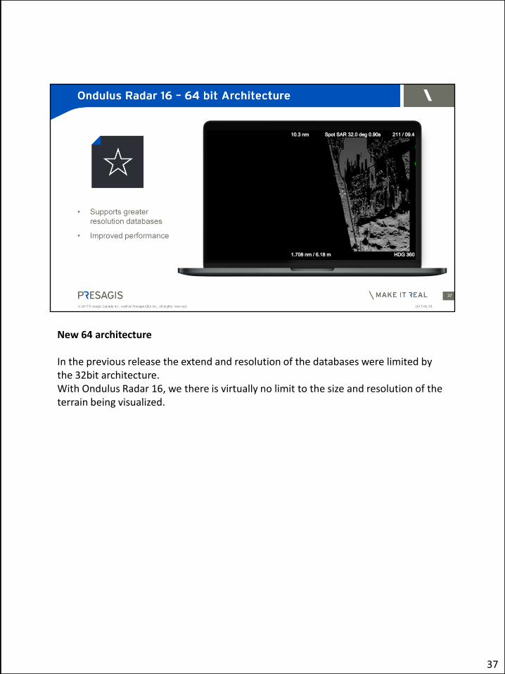
New 64 architecture In the previous release the extend and resolution of the databases were limited by the 32bit architecture. With Ondulus Radar 16, we there is virtually no limit to the size and resolution of the terrain being visualized.
37

Included with the RBGM License Includes Pre Defined Storm Fronts See storm shape in the right screen is now part on the RBGM terrain in the left screen. Left: terrain and cloud front Right: storm front
38

Star effects are Important cues in radar simulation. Like the glitter of stars in the night sky, these effects appear when the radar beam hit the sharp edge of a building.
39
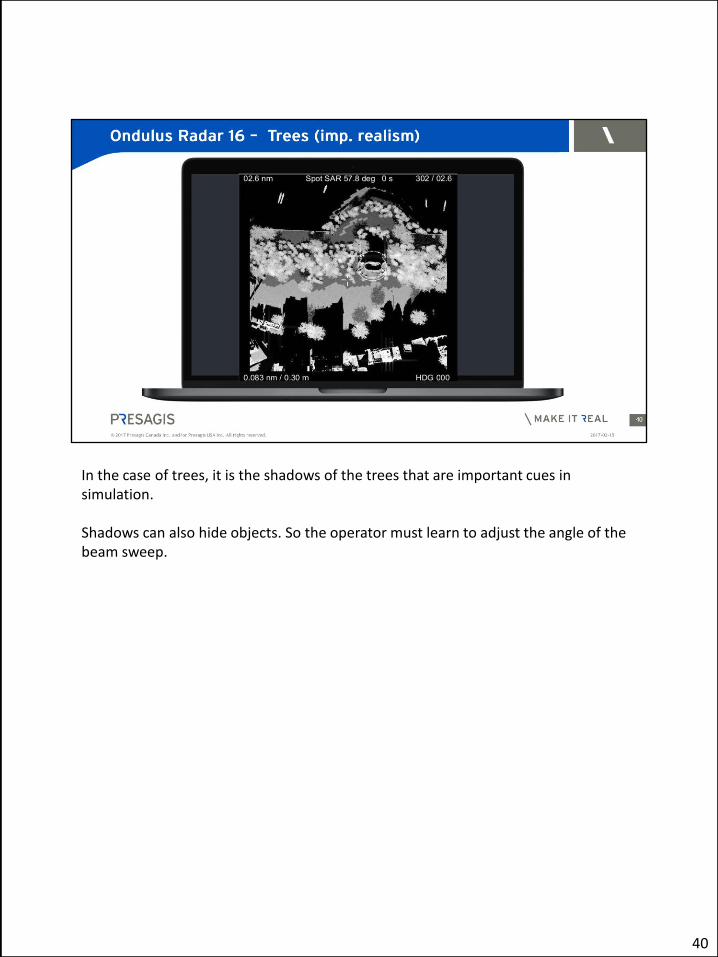
In the case of trees, it is the shadows of the trees that are important cues in simulation. Shadows can also hide objects. So the operator must learn to adjust the angle of the beam sweep.
40
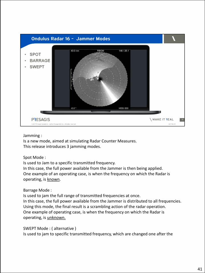
Jamming : Is a new mode, aimed at simulating Radar Counter Measures. This release introduces 3 jamming modes. Spot Mode : Is used to Jam to a specific transmitted frequency. In this case, the full power available from the Jammer is then being applied. One example of an operating case, is when the frequency on which the Radar is operating, is known. Barrage Mode : Is used to jam the full range of transmitted frequencies at once. In this case, the full power available from the Jammer is distributed to all frequencies. Using this mode, the final result is a scrambling action of the radar operation. One example of operating case, is when the frequency on which the Radar is operating, is unknown. SWEPT Mode : ( alternative ) Is used to jam to specific transmitted frequency, which are changed one after the
41

other. In this case, the full power available from the Jammer is then being applied, but on a single frequency. One example of operating case, is when you want to corrupt the radar operation momentarily to mislead the operator.
41
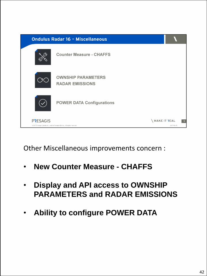
Other Miscellaneous improvements concern : • New Counter Measure - CHAFFS
• Display and API access to OWNSHIP
PARAMETERS and RADAR EMISSIONS
• Ability to configure POWER DATA
42

With FlightSim and HeliSIM you will find : MAIN FEATURES around : • Improved Model Quality • Features to improve Integration • GUI Interaction Simplification • 100+ improvements
43
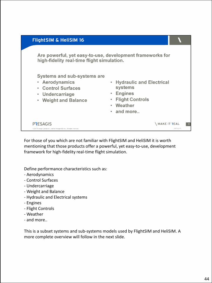
For those of you which are not familiar with FlightSIM and HeliSIM it is worth mentioning that those products offer a powerful, yet easy-to-use, development framework for high-fidelity real-time flight simulation. Define performance characteristics such as: - Aerodynamics - Control Surfaces - Undercarriage - Weight and Balance - Hydraulic and Electrical systems - Engines - Flight Controls - Weather - and more.. This is a subset systems and sub-systems models used by FlightSIM and HeliSIM. A more complete overview will follow in the next slide.
44
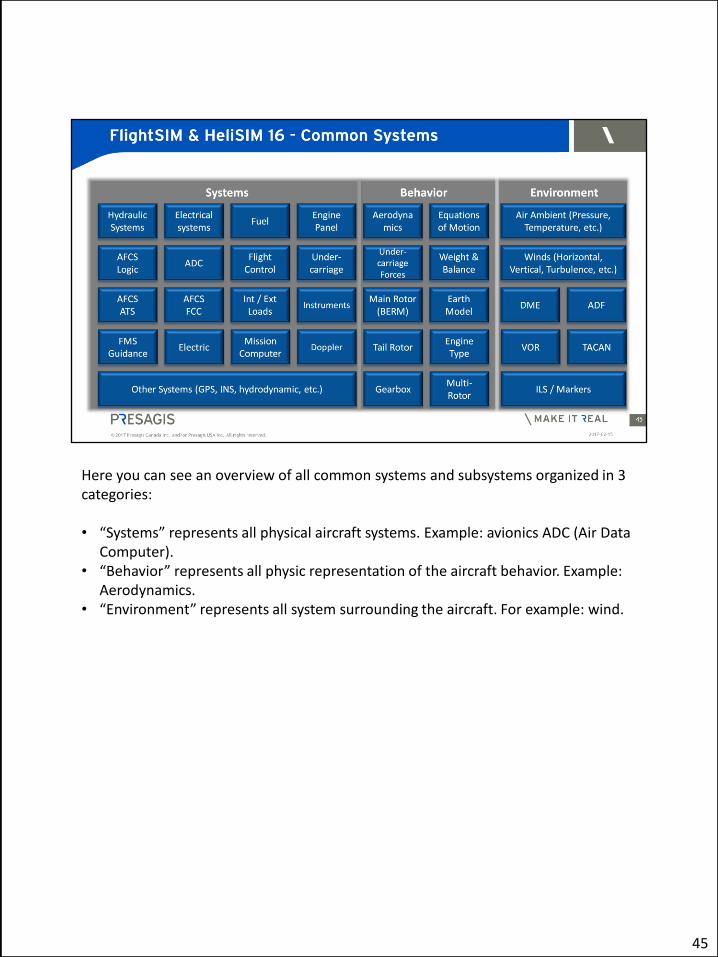
Here you can see an overview of all common systems and subsystems organized in 3 categories: • “Systems” represents all physical aircraft systems. Example: avionics ADC (Air Data
Computer). • “Behavior” represents all physic representation of the aircraft behavior. Example:
Aerodynamics. • “Environment” represents all system surrounding the aircraft. For example: wind.
45

These updates are applicable for both FlightSIM and HeliSIM System Enhancements
Radar altitude can be positioned in the aircraft with corrected offset (Now you will see 0 ft altitude on ground). Wind Systems now allowed to be set and modified in run-time turbulence. New Auto Flight Control System (AFCS) Functions Users can parameter autopilot (AFCS) limits
This allows them to Open the characterization of the AFCS limit (no limits in complexity) in the product without need to build user plug-in code.
User can now modify AFCS reference in run-time. AFCS can now engage one axis per one axis.
New Fight Management System (FMS) Functions FMS can now engage one axis per one axis. FMS has more waypoint definition as needed by UAV navigation FMS and AFCS can select Altitude reference type (geodetic, Barometric,
46

standard and radar)
46

These updates are applicable to HeliSIM only Tail rotor system has been extended to add more modelization capabilities • Tail Rotor Torque is now transmitted to the engine (need for autorotation phase of
flight). • Tail Rotor azimuth angle can now be configured • Support for total failure malfunction for the tail rotor ( complete rotor blade jam) Gearbox system now contain rotor brake model New Auto Pilot modes • Rate limit mode (Use with the Heading Select mode). • Course track mode (tail control in hover and roll control in forward speed).
• Specific Updates
47
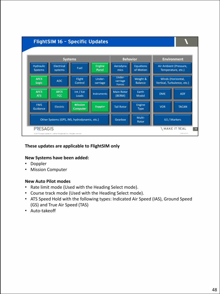
These updates are applicable to FlightSIM only New Systems have been added: • Doppler • Mission Computer New Auto Pilot modes • Rate limit mode (Used with the Heading Select mode). • Course track mode (Used with the Heading Select mode). • ATS Speed Hold with the following types: Indicated Air Speed (IAS), Ground Speed
(GS) and True Air Speed (TAS) • Auto-takeoff
48

One of our main focus in this release is to simplify the integration our products with Hardware devices. Hardware help functionalities enhancement Calibration dead bands User trim switches Control loader example as requested by customer More jettison internal and external switches New functionalities enhancement to help Building aircraft model Additional load can be defined outside the aircraft model that allowed any aircraft model to select it. Additional load has been split in to type Internal and external (add aerodynamic curves definition and set the orientation of the load at the attachment point) Additional load can be control at runtime Dynamic Test Integrity tools improvement allowed Inputs handling for dynamic tests to be relative or absolute. The user can now replicate more precisely flight test. Increased controls during Runtime
49

Restart on crash, Flight freeze (position) And more
GUI interaction simplification (*)
49

Before concluding, we would like to remind you that we have added value to our current maintenance program.
The new maintenance offer which includes currently: • Tech support• Bug fixes• Upgrades• Licensed transfers
Now it includes a choice of 4 enhanced support package: • Customer Product Training• Program Kickoff• Architectural guidance• Application Performance Optimization
50

51