improvement of the earthquake resistance of incrementally ... · improvement of the earthquake...
TRANSCRIPT
Improvement of the Earthquake Resistance of
Incrementally Launched Concrete Bridges
S.D. Tegou & I.A. Tegos Department of Civil Engineering, Aristotle University of Thessaloniki, Greece
SUMMARY: The deck of incrementally launched concrete bridges is continuous without internal joints and is usually
supported on piers and abutments through rubber bearings. As a result the seismic movements of the piers’ head
are not coincided with the corresponding displacements of the deck. According to Code’s provisions, these
bridges, as well as precast I-beam bridges, are considered as structures with limited ductile behaviour and are
analyzed for values of the behaviour factor less or equal to 1.5. In this study the connection of the bridge deck
with contiguous piers is proposed, on the presumption that the serviceability requirements of the bridge are
properly accommodated. According to this methodology, the longitudinal design seismic action is transmitted to
the restrained piers which develop their hysteretic behaviour while the bridge deck is supported on the non-
active piers and abutments through sliding bearings. In the transverse direction of the bridge in which the
serviceability requirements are not critical, seismic links restrain the movements of the deck. The
aforementioned modification is necessary so that a new restraining system aiming at the limitation of the bridge
seismic movements to be afterwards integrated in the ductile system. The efficiency of the innovative proposal is
assessed by utilizing an incrementally launched concrete bridge of Egnatia Odos Motorway in Greece.
Keywords: Incremental, bridge, ductile, seismic, isolation
1. INTRODUCTION
There are many parameters affecting the selection of bridge type, span arrangement and general
layout. More specifically, the choice of the deck type is influenced by the particular site constraints
while the advantages and disadvantages of each type need to be carefully considered to determine the
optimum solution. In general, bridge deck may consist of beams or boxes, cast in place or precast,
lifted or launched into place. Depending on the method used for the construction of the bridge deck, it
can be either monolithically connected to the piers or simply supported on these members.
Precast concrete bridges with cast in situ concrete deck slab (CEB-FIB 2004) and incrementally
lunched bridges are of the most common bridges in which the deck is supported on piers through
bearings. In these bridges, the presence of bearings results in the lengthening of the natural period of
the system and consequently, in significant reduction in the earthquake induced forces. However, in
high seismicity regions, the main disadvantage of these bridge systems is the sensitivity to seismic
displacements (Priestley et al. 1996). These could be limited by utilizing energy dissipation devices
(Kelly 2001a; Kelly 2001b; Naeim and Kelly 1999; Ruangrrassamee and Kawashima 2003), which
however, increases the total construction cost of the bridge.
In general, the better compromise between cost effectiveness and seismic safety of structures, not only
bridges but also buildings, is achieved more easily through the ability of the structures to dissipate
considerable amount of energy, namely the ductility, rather than through their elastic response.
Ductility is a conceptual property of bridges whose piers are rigidly connected to the deck as in this
case their hysteretic behaviour is developed in order to reduce the seismic actions by introducing a
behaviour factor q. However, according to the Code provisions (Eurocode 8-Part 2 2003), bridges
whose deck is supported on piers through bearings are considered as structures with limited ductile

behaviour and analyzed for values of the behaviour factor less or equal to 1.5. It is known that despite
the fact that the seismic actions are effectively reduced due to the presence of the bearings, which
increase the flexibility of the system, the aforementioned design leads to conservative dimensioning of
the piers, foundations and bearings, especially in high seismicity regions.
The investigation on the improvement of the earthquake resistance and cost effectiveness of precast I –
beam bridges and incrementally lunched bridges consists a quite interesting subject. The seismic
improvement of the earthquake resistance of precast I-bam bridges was analytically investigated in a
previous study (Tegou and Tegos 2011), where was presented a seismic design methodology
compatible with the Code provisions (Eurocode 8-Part 2 2003). This study proposes a structural
configuration of the pier- to- deck connection which improves the earthquake resistance of
incrementally launched bridges. The proposed methodology gives the opportunity to design
incrementally launched bridges as ductile structures, provided that the longitudinal seismic action is
transmitted to contiguous piers of the bridge and consequently, provides values of the behaviour factor
q greater to 1.5 in both directions. The further improvement of the earthquake resistance as well as the
reduction in the seismic displacements of these systems can be achieved through alternative methods
proposed in a recent study (Tegou et al. 2010).
2. DESCRIPTION OF THE PROPOSED STRUCTURAL CONFIGURATION
In this study the seismic design of bridges, constructed with the incremental launching method, by
considering a value of the behaviour factor in the longitudinal direction greater to one, is investigated.
Seismic links are used to transmit the longitudinal design seismic action to contiguous piers,
preferably the tallest ones, provided that serviceability requirements are preserved. The simplified
proposed methodology assumes that the seismic links are continuously activated and restrain the
movements of the deck. The aforementioned seismic links are combined with elastomeric bearings
which allow the free rotation of the supported nodes. The deck is supported on the other piers through
sliding bearings, which allow the movement of the deck in the longitudinal direction. The transverse
movement of the deck is also restrained through seismic links.
The proposed methodology is based on the provisions of Eurocode 8-Part 2 (2003) referring to the use
of seismic links in the longitudinal direction of the bridge. It is quoted in the Code in paragraph 6.6.3.1
that elastomeric bearings may be used in combination with seismic links which are designed to carry
the design seismic actions. During earthquake, seismic links shall not allow movement, although
simultaneously, they shall not prevent the rotation of the supported nodes around the horizontal axes.
In transverse direction, in which the serviceability requirements are not critical, the movement of the
deck shall be restrained. The Greek Code for Seismic Resistant Bridges (Ministry of public works of
Greece 2007) included similar provisions about the use of seismic links in the longitudinal direction of
the bridge. The seismic design of incrementally launched bridges for a value of the behaviour factor
greater to one, as well as the consequent reduction in the design seismic actions leads to smaller pier
cross-sections requirements.
Fig. 2.1 shows the structural configuration of the seismic links, which consist of a tenon and mortise
connection between pier and bridge deck. This connection includes the formation of a circular section
hole (D=1.0m) at the pier’s head during its construction. An expanded polystyrene layer (t=10mm),
placed around the perimeter of the hole, provides the adequate margin for the rotation of the pier’s
head due to serviceability requirements of the bridge. However, in bridges with different height of
piers a scale of the thickness of this layer is probably required in order for the serviceability
requirements to be fulfilled. Steel bars of 12mm or 14mm diameter are arranged in a grid of 125mm x
125mm into the hole and are lapped with similar bars. The hole is filled with high strength concrete.
The lapped bars are anchored at the deck’s slab where the construction of a similar hole is predicted
during the casting. These bars behave as dowels which intersect the surface and provide adequate
corporation between bridge deck and pier. This issue was experimentally investigated by the Authors
in a previous work (Tegou and Tegos 2009).

Bridge design also provides a hierarchy of the resistances of its structural components, which ensures
that the seismic link has adequate resistance to resist the serviceability and seismic loading of the
bridge so that the yielding of the longitudinal reinforcement at the pier’s base to precede its failure.
The reduction of the compression zone due to the construction of the hole can be balanced through the
extension of the bottom deck slab toward the right and left side of the pier. As far as the torsional
resistance of the deck’s cross-section is concerned, we should note that it is not significantly be
affected, due to the small diameter of the hole in comparison to the dimensions of the deck.
Figure 2.1. Structural configuration of the seismic link at the pier’s head
3. DESCRIPTION OF THE “REFERENCE” BRIDGE
The efficiency of the proposed methodology was assessed by utilizing a bridge of Egnatia Odos
Motorway in Greece constructed with the incremental launching method, Fig. 3.1. This bridge consists
of two independent branches with similar lengths and cross-sections, while the main difference
between them is the varied height of the piers from 12.0m to 28.0m.
Both branches of the bridge (right and left) are curved in plan, Fig. 3.1(c), with a radius R=1175m
R=1150m respectively, while the deck section is laterally inclined (in the transverse direction). The
end spans of the right branch, Fig. 3.1(a), are 36.7m and 35.5m long respectively and the intermediate
nine spans are 45.5m long. Hence the length of this bridge that has eleven spans in total is 481.7m.
The left branch has also eleven spans and its total length is 471.3m, Fig. 3.1(b). In both bridges, the
deck is a single-cell box girder with 9 different sections along its length. All piers are connected to the
deck through low damping elastomeric or PTFE bearings. Two fluid dampers in each direction
(longitudinal and transverse) are used at the abutments, where the only joints of the bridge deck are
located. The dampers have practically hysteretic behaviour, since they realize a velocity exponent a
(F=C.va) as low as 0.05. The maximum strength they provide is 750 kN and 450 kN per damper, in the
longitudinal and transverse direction, respectively.

According to the Greek seismic design code (Ministry of public works of Greece 2000), the bridge is
founded on a ground type B. It is noted that the corner periods of the spectrum used are 0.15s and
0.60s for ground type B, and this corresponds to a ground type between B and C according to
Eurocode 8 (Eurocode 8- Part 1 2003). The design ground acceleration is equal to 0.16g. The adopted
importance factor is equal to γΙ=1.3, while the behaviour factors are equal to 1.0 for both horizontal
directions and also 1.0 for the vertical seismic action.
Figure 3.1. (a) Longitudinal section of the right branch of the “reference” bridge, (b) Longitudinal section of the
left branch of the “reference” bridge, (c) Plan view, (d) The deck’s cross-section at the mid-span and (e) The
pier’s cross-section
4. MODELLING OF THE ANALYZED BRIDGE SYSTEMS
The as-built bridge systems given in Fig. 3.1 and the modified, according to the proposed method,
bridges were modelled and analyzed for the purposes of the present study. An indicative stick model
of the analyzed bridge systems is given in Fig. 4.1. A finer mesh was used close to the deck-pier
connections, to accurately capture stress concentrations, as well as the deformation of the deck.
Both bearings and dampers were modelled using inelastic spring elements, with 6 degrees of freedom,
which, in the case of elastic analysis, remain elastic. Bearings were modelled using their actual height
and effective properties for their five significant degrees of freedom, (their rotational stiffness around

the vertical axis was considered negligible), according to Naeim and Kelly (1999). Stiff zones were
used in order to take into account the distance of the centre of gravity of the deck’s cross-section from
the head of the bearings and also the width of the pier’s head, see Detail 2 in Fig. 4.1. In the case of
the elastic analysis, the dampers were modelled through an equivalent viscous damping ratio and their
secant stiffness at the maximum displacement, instead of directly modelling their hysteretic behaviour
that is not feasible in this case. The flexibility of the piers’ foundations was also taken into account by
assigning spring elements. These spring values were obtained by the in-situ geotechnical tests
conducted for the design of the as-built bridges of Fig. 3.1.
The “reference” bridge models were exploited for the modelling of the modified bridge systems. Both
models -initial and modified- had the same length and the same deck and pier cross-section while the
dampers were removed from the new models. The piers, foundations and bearings of the modified
bridge systems were re-designed by applying linear modal response spectrum analysis, taking into
account the piers’ capacity to resist seismic actions by introducing the behaviour factor q.
In the case of the right branch of the reference bridge, Fig. 3.1(a), seismic links were considered to
restrain the movements of all piers’ heads as the serviceability requirements are properly
accommodated through their flexibility. The deck is supported on the abutments by sliding bearings.
On the other hand, in the case of the left branch of the reference bridge, Fig. 3.1(b), which is stiffer
than the right one due to the shorter height of the piers, seismic links are implemented only at piers P1
to P4 which are the tallest contiguous piers of the bridge, while the support of the deck on the rest
piers and abutments is accomplished by sliding bearings. We should note here that the connection of
the central piers to the deck is the optimum selection to compromise the serviceability deformations,
as the bridge deck is contracted toward its center. However in this case, the ground conditions do not
allow the connection of the four central piers as they are significantly shorter than piers P1 to P4.
Figure 4.1. The model of the analysed bridge systems
As mentioned in the description of the proposed methodology, the seismic links are continuously
activated during earthquake, restrain the bearings’ deformations and allow the rotation of the
supported nodes. Thus these elements were modelled by considering that the deck is connected to the
piers’ head through moment hinge connections, Detail 2 in Fig. 4.1. The bearings were modelled by
M1
M3
M2
M7
M4
M6
M5
M8
M9
M10
A11
A0
Detail 1

link elements as in the case of the initial bridges. The foundation was modelled as in the “reference”
bridge models with spring elements.
5. RESULTS
5.1. Modal response of the studied bridges
The comparison of the modal response of the initial and the modified bridge systems was considered
to be essential, as the construction of the seismic links at the piers’ heads is expected to modify
strongly the dynamic properties and response of the bridges.
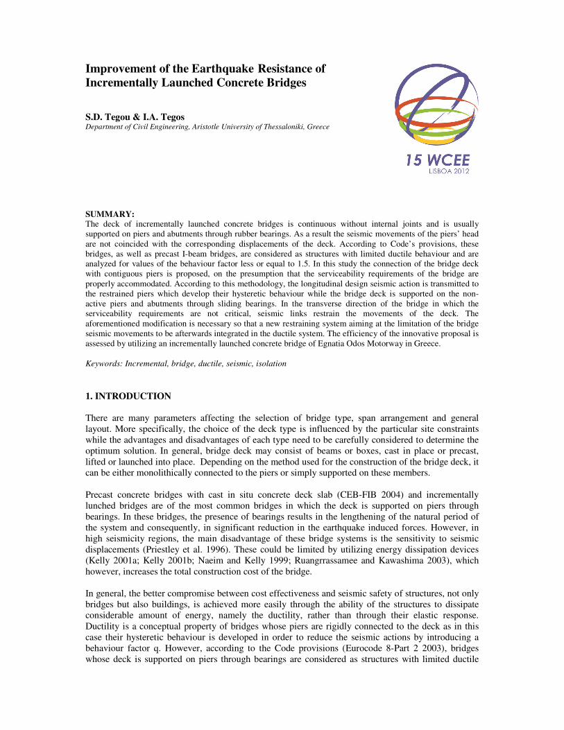
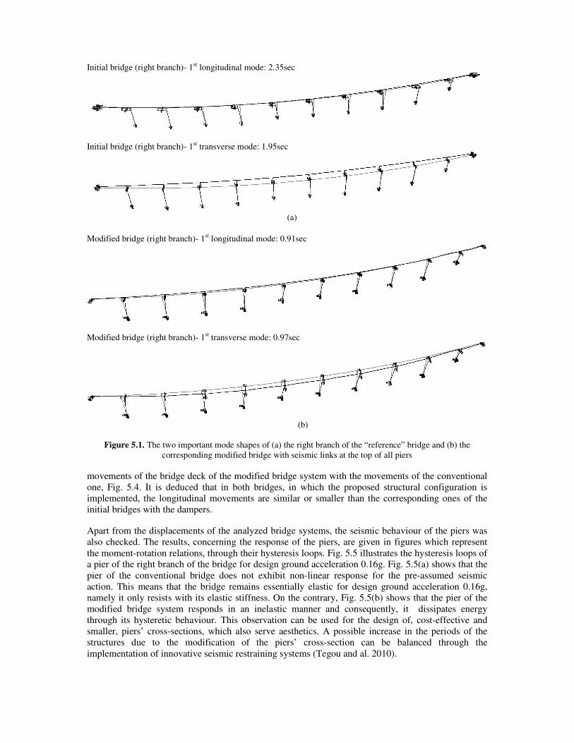
In Fig. 5.1 two important mode shapes of the initial and the modified bridge system with the tall piers
(right branch of the reference bridge) are correspondingly given. The comparison of Fig. 5.1(a) and
5.1(b) shows that the construction of the seismic links at the top of the piers increases the overall
stiffness of the bridge. Specifically, the period of the first longitudinal mode shape of the
unconventional bridge system is reduced by 62%, in comparison to the period of the conventional one.
The first longitudinal period of the conventional bridge system is 2.35s, see Fig. 5.1(a), while the first
longitudinal period of the modified bridge system is 0.91s, see Fig. 5.1(b). Correspondingly, the period
of the first transverse mode shape of the modified bridge system is reduced by 50%, in comparison to
the period of the conventional one. The transverse period of the conventional bridge system is 1.95s,
see Fig. 5.1(a), while the transverse period of the modified bridge system is 0.97s, see Fig. 5.1(b). It is
observed that the dynamic system in the transverse direction of the bridge is also significantly
influenced.
Similar conclusions can be extracted from the comparison between the modal response of the initial
and modified bridge of the left branch, see Fig. 5.2. In this case, although the construction of seismic
links at the head of all piers was not accomplishable, due to the restrictions of the serviceability
requirements of the bridge, the moment-hinge connection of four of the ten piers of the bridge modify
strongly the dynamic properties and response of the initial bridge. Specifically, the period of the first
longitudinal and transverse modal periods are correspondingly reduced by 61% and 7%.
5.2. Nonlinear time history analysis of the studied bridges
The seismic performance of the conventional and modified bridge systems was assessed using
nonlinear time history analysis. Analysis was carried out by using the SAP 2000 program (Computers
and structures 2007). The “reference” finite element models involved beam elements, Fig. 4.1, while
appropriate nonlinear links were utilized for time-history analysis, too. A compatible lumped plasticity
model was used. The input parameters of the moment-rotation (Μ-θ) relationship (i.e. bilinear with 2–
5% hardening, depending on the calculated ultimate moment) were determined by fibre analysis
performed in the computer program RCCOLA-90 (Kappos 2002) for each particular cross-section.
Five artificial records compatible with the Eurocode 8 (2003) elastic spectrum and corresponded to
0.16g ground accelerations were used. The Newmark γ=1/2, β=1/4 integration method was used, with
time step ∆t =0.01 s and a total of 2000 steps (20 s of input). The plastic hinging in the piers was
modelled by considering nonlinear rotational spring elements at the ends of the piers.
The reduction in the modal periods of the modified bridge systems was found to lead in increases in its
seismic loads, due to the fact that the modal periods are closer to the dominant periods of the response
spectrum. Despite this fact, the study showed that the movements of the deck of the unconventional
bridge systems are reduced. Fig. 5.3 shows the time histories of the seismic displacements of the
central joint of the deck for the two analyzed bridge systems. It is derived that the unconventional
bridge systems respond with similar or smaller displacements in the longitudinal direction. The time
histories also show that the overall resisting system of the unconventional bridges becomes stiffer.
The efficiency of the proposed design methodology was also assessed by comparing the longitudinal
Initial bridge (right branch)- 1st longitudinal mode: 2.35sec
Initial bridge (right branch)- 1st transverse mode: 1.95sec
(a)
Modified bridge (right branch)- 1
st longitudinal mode: 0.91sec
Modified bridge (right branch)- 1st transverse mode: 0.97sec
(b)
Figure 5.1. The two important mode shapes of (a) the right branch of the “reference” bridge and (b) the
corresponding modified bridge with seismic links at the top of all piers
movements of the bridge deck of the modified bridge system with the movements of the conventional
one, Fig. 5.4. It is deduced that in both bridges, in which the proposed structural configuration is
implemented, the longitudinal movements are similar or smaller than the corresponding ones of the
initial bridges with the dampers.
Apart from the displacements of the analyzed bridge systems, the seismic behaviour of the piers was
also checked. The results, concerning the response of the piers, are given in figures which represent
the moment-rotation relations, through their hysteresis loops. Fig. 5.5 illustrates the hysteresis loops of
a pier of the right branch of the bridge for design ground acceleration 0.16g. Fig. 5.5(a) shows that the
pier of the conventional bridge does not exhibit non-linear response for the pre-assumed seismic
action. This means that the bridge remains essentially elastic for design ground acceleration 0.16g,
namely it only resists with its elastic stiffness. On the contrary, Fig. 5.5(b) shows that the pier of the
modified bridge system responds in an inelastic manner and consequently, it dissipates energy
through its hysteretic behaviour. This observation can be used for the design of, cost-effective and
smaller, piers’ cross-sections, which also serve aesthetics. A possible increase in the periods of the
structures due to the modification of the piers’ cross-section can be balanced through the
implementation of innovative seismic restraining systems (Tegou and al. 2010).

Initial bridge (left branch)- 1st longitudinal mode: 2.15sec
Initial bridge (left branch)- 1st transverse mode: 2.00sec
(a)
Modified bridge (left branch)- 1st longitudinal mode: 0.83sec
Modified bridge (left branch)- 1
st transverse mode: 1.86sec
(b)
Figure 5.2. The two important mode shapes of (a) the left branch of the reference bridge and (b) the
corresponding modified bridge with seismic links at the top of piers P1, P2, P3, and P4
-80
-60
-40
-20
0
20
40
60
80
0 5 10 15 20
lon
git
udin
al d
isp
lace
men
t (m
m)
t(sec)
"Modified Bridge" "Conventional Bridge"
-80
-60
-40
-20
0
20
40
60
80
0 5 10 15 20
lon
git
udin
al d
isp
lace
men
t (m
m)
t(sec)
"Modified Bridge" "Conventional Bridge"
(a) Right Branch (tall piers) (b) Left Branch (short piers)
Figure 5.3. Comparison of the time histories of the longitudinal displacements of the deck of the conventional
and the modified bridge system: (a) right branch (tall piers) and (b) left branch (short piers)

0
10
20
30
40
50
60
70
80
A1
2
P1
3
P1
4
P1
5
P1
6
P1
7
P1
8
P1
9
P2
0
P2
1
P2
2
A2
3longit
udin
al
dis
pla
cem
ents
of
the
dec
k(m
m)
Modified Bridge Conventional Bridge
0
10
20
30
40
50
60
70
80
A0
P1
P2
P3
P4
P5
P6
P7
P8
P9
P1
0
A11longit
udin
al d
ispla
cem
ents
of
the
dec
k(m
m)
Modified Bridge Conventional Bridge
(a) (b)
Figure 5.4. The longitudinal displacements of the deck of the conventional and the modified bridge system: (a)
right branch (tall piers) and (b) left branch (short piers)
-60000
-40000
-20000
0
20000
40000
60000
80000
-4.0E-03 -2.0E-03 0.0E+00 2.0E-03 4.0E-03
Mo
men
t M
(k
N-m
)
Rotation θ (rad)
(a) (b)
Figure 5.5. The hysteresis loops of a pier for design ground acceleration 0.16g: (a) conventional bridge and (b)
modified bridge
In the case of the right branch, the flexibility of the piers increases the movements of the bridge. As a
result the use of hydraulic dampers for the reduction of the bridge movements was inevitable.
Although the increase of the period of the structure reduces the seismic loads, the construction cost of
the bridge is significantly increased due to the use of expensive seismic isolation devices. The solution
proposed in this study, effectively reduces the period of the structure and consequently increases the
induced seismic loads. However the conversion of the bridge to a ductile system and its capacity to
resist seismic actions in the non-linear range of response leads to the design for resistance to seismic
forces smaller than those corresponding to a linear elastic response and similar to the forces of the
conventional seismic isolated bridge. As a result the main advantage of the proposed solution is the
avoidance of the use of the dampers through the connection of some of the piers to the deck. The
aforementioned economy also overbalances possible increase in the structural cost, due to the
additional confinement requirements required for ductile structures.
6. CONCLUSIONS
In the present study the seismic efficiency of a new configuration, aiming at the improvement of the
earthquake resistance of incrementally launched bridges, was analytically investigated. The proposed
configuration includes the construction of seismic links which are used to transmit the longitudinal
design seismic action to contiguous piers, provided that serviceability requirements are preserved. It is
desirable to outline the following, as the main results of the delivered study:
Incrementally launched bridges can be designed as ductile structures. As a result, a behaviour factor

less or equal to 3.5 may be used.
The proposed seismic links can be implemented in bridges constructed with the incremental launching
method without regard to the piers height. The serviceability requirements of the bridge are properly
accommodated through the number of the seismic active piers, while the support of the deck on the
other piers is accomplished by using sliding bearings. The piers’ cross-section can also be properly
modified in order for the serviceability requirements to be fulfilled.
Depending on the number of the seismic active piers, in which the proposed seismic links are
constructed, the maximum seismic displacements of the bridge are similar or smaller than the
displacements of the initial seismic isolated bridge systems without the need of use of high cost
seismic isolation devices (e.g. dampers).
The proposed seismic links do not have construction problems, while, from the economic point of
view, they have minor cost considering their effectiveness on the longitudinal earthquake, which is
generally more difficult to be treated than the transverse one. In bridges with relatively short piers, in
which the second order effects do not significantly affect the performance of the bridge, the
implementation of the proposed method leads to smaller pier cross-sections, which are advantageous
as far as their earthquake resistance and aesthetics are concerned.
AKCNOWLEDGEMENT
This research has been co-financed by the European Union (European Social Fund – ESF) and Greek national
funds through the Operational Program "Education and Lifelong Learning" of the National Strategic Reference
Framework (NSRF) - Research Funding Program: Heracleitus II. Investing in knowledge society through the
European Social Fund.
Acknowledgements are due to EGNATIA ODOS S.A. for providing all the necessary information and drawings
of the studied bridges.
REFERENCES
CEB-FIB (2004). Precast concrete bridges State-of-the-art report, bulletin 29, fib Task Group 6.4, Switzerland.
CEN (2003). Eurocode 8: Design of structures for earthquake resistance, Part 2: Bridges.
CEN (2003). Eurocode 8: Design of structures for earthquake resistance, Part 1: General rules, seismic actions
and rules for buildings.
Computers and Structures Inc. (2007). SAP 2000 Nonlinear Version 11.0.3, User’s Reference Manual,
California.
Kappos, A.J. (2002). RCCOLA-90: A microcomputer program for the analysis of the inelastic response of
reinforced concrete sections. Dept. of Civ. Eng. Aristotle University of Thessaloniki, Greece.
Kelly, T.E. (2001a). Base isolation of structures, Design guidelines, S.E. Holmes Consulting Group Ltd.
Kelly, T.E. (2001b). In structure dumping and energy dissipation, S.E. Holmes Consulting Group Ltd.
Ministry of public works of Greece (2000). Greek seismic code-EAK2000, Athens, Greece, (In Greek).
Ministry of public works of Greece (2007). Guidelines for Seismic Design of Bridges in Combination with DIN-
FB 102 103, 104, Athens, Greece, (In Greek).
Naeim, F. and Kelly, J.M. (1999). Design of seismic isolated structures, From theory to practice, John Wiley &
Sons, New York.
Priestley, M., Seible, F. and Calvi, G. (1996). Seismic Design and Retrofit of Bridges, John Wiley & Sons, New
York.
Ruangrassamee, A., Kawashima, K., (2003). Control of nonlinear bridge response with pounding effect by
variable dampers. Engineering Structures 25:5, 593–606.
Tegou, S.D., Mitoulis, S.A. and Tegos, I.A. (2010). An unconventional earthquake resistant abutment with
transversely directed R/C walls. Engineering Structures 32: 11, 3801-3816.
Tegou, S.D. and Tegos, I.A. (2009). Experimental investigation on the shear transfer between concrete interfaces
of Slab-and-Beam Bridge Deck Structures. 16th Greek Conference on Concrete Structures. CD ROM
Proceedings, Paper No. 091001, Pafos, Cyprus, (in Greek).
Tegou, S.D. and Tegos, I.A. (2011). A proposal for cost-effective design of precast I-beam bridges. International
Conference on Innovations on Bridges and Soil- Bridge Interaction. Vol I: 149-156.