improved heuristic drift elimination with magnetically ... sci... · improved heuristic drift...
TRANSCRIPT

Improved Heuristic Drift Elimination withMagnetically-aided Dominant Directions (MiHDE)for Pedestrian Navigation in Complex Buildings
A.R. Jimenez, F. Seco, F. Zampella, J.C. Prieto and J. GuevaraCentre for Automation and Robotics (CAR)
Consejo Superior de Investigaciones Cientıficas (CSIC)-UPM.Ctra. Campo Real km 0.2, 28500 La Poveda, Arganda del Rey (Madrid), Spain.
e-mail: [email protected] Web: http://www.car.upm-csic.es/lopsi
Abstract—The main problem of Pedestrian Dead-Reckoning(PDR) using only a body-attached IMU is the accumulationof heading errors. The heading provided by magnetometersin indoor buildings is in general not reliable and therefore itis commonly not used. Recently, a new method was proposedcalled Heuristic Drift Elimination (HDE) that minimizes theheading error when navigating in buildings. It assumes thatthe majority of buildings have their corridors parallel to e achother, or they intersect at right angles, and consequently mostof the time the person walks along a straight path with aheading constrained to one of four possible directions. In thispaper we study the performance of HDE-based methods incomplex buildings, i.e. with pathways also oriented at 45o, longcurved corridors, and wide areas where non-oriented motionis possible. We explain how the performance of the originalHDE method can be deteriorated in complex buildings, and also,how severe errors can appear in case of false matches with thebuilding’s dominant directions. Although magnetic compassingindoors has a chaotic behavior, in this paper we analyze largedata-sets in order to study the potential use that magneticcompassing has to estimate the absolute yaw angle of a walkingperson. Apart from these analysis, this paper also proposesan improved HDE method called MiHDE (Magnetically-aidedImproved Heuristic Drift Elimination), that is implemente d overa PDR framework that uses foot-mounted inertial navigationwith an Extended Kalman Filter (EKF). The EKF is fed withthe MiHDE-estimated orientation error, gyro bias corrections, aswell as the confidence over that corrections. We experimentallyevaluated the performance of the proposed MiHDE-based PDRmethod, comparing it with the original HDE implementation.Results show that both methods perform very well in idealorthogonal narrow-corridor buildings, and MiHDE outperfo rmsHDE for non-ideal trajectories (e.g. curved paths) and alsomakesit robust against potential false dominant direction matchings.
I. I NTRODUCTION
The main problem of Pedestrian Dead-Reckoning (PDR)using only a body-attached IMU (Inertial Measurement Unit)is the accumulation of heading errors. The heading providedby magnetometers in indoor buildings is in general notreliable, and consequently is not commonly used in the PDRcommunity for accurate navigation. Recently, a new methodwas proposed by Borenstein and Ojeda [1] calledHeuristicDrift Elimination (HDE) that minimizes the heading errorwhen navigating in buildings. It assumes that the majority ofbuildings have dominant directions defined by the orientation
of their corridors; consequently a person walks most ofthe time along straight-line paths parallel to these dominantdirections. Abdulrahim et al. [2] exploit the samebuilding’sdominant directionsassumption, but they implement the HDEidea in a totally different way. See Fig. 1 for a simplifieddescription of a PDR algorithm, which is similar to theAbdulrahim et al. implementation, that uses the DominantDirection-based heuristic.
The implementation in [1] uses a feedback control loop atthe output of a vertically-aligned gyroscope. In the loop thereis an integration stage to obtain the heading angle from thegyroscopic angular rate, and then this angle is compared toone of the main building orientations. The heading error isfed into a binary integral (I)-controller, whose output is anestimation of the slow-changing bias of the gyroscope, whichis subtracted from the measured gyroscopic angular rate toobtain an “unbiased” version of the gyro’s angular rate. TheI-controller has a gain proportional to the size of the step,sothe gyro bias is computed preferably with long steps.
The implementation in [2] uses an inertial navigation orINS-based framework to directly integrate triads of accelerom-eter and gyroscopic signals. This INS mechanization is correc-ted by a complementary Kalman filter (see [3] and [4] for INS-based PDR implementation details). The heading differencebetween the dominant directions of the building and that ofthe user’s stride (heading error) is fed as a measurement intothe Kalman filter. When the Stride Length (SL) is shorter than0.3 m, the heading correction is deactivated.
These two works ([1], [2]) exploit the concept of the domi-nant directions in a building but do not use magnetometers togive information about the absolute heading or yaw angle ofthe person while is walking. They state that this informationis not reliable enough and avoid its use. However, recentlysome proposals try to obtain benefits from perturbed magneticinformation using complex arrays of magnetometer to partiallycompensate yaw errors [5], and also, capturing the totalmagnetic field change at foot stances in order to improve theestimation of gyro biases [6]. Other approaches are possible,as will be proposed in this paper, where we use improvedheuristics based on building’s dominant directions, and alsoyaw information obtained by mid-term magnetic compassing.

North
Building'sDominantDirections
90º
Estimated
True trajectory
Foot Stances
Kalman Filter
IMU INS
Yaw - ClosestBuilding'sDomint Direction
Yawerror
VelocityCorrectionsat Stance
IMU
Yaw error
Position
Attitude(Roll,Pitch,& Yaw)
Acc
Gyr
Measurements
a)
b)
Fig. 1. Pedestrian Dead-Reckoning (PDR) with the HDE heuristic. a)The basic INS-based PDR approach extended with the HDE heuristic thatuses information from the main Building’s Dominant Directions (green colorblock). b) Trajectory in a building with 2 dominant directions (horizontal& vertical). Note that there is an error in Yaw, specially at the end of thetrajectory, between the estimated yaw and the yaw of the closest dominantdirection (horizontal). This Yaw error can be used by the HDEheuristic tocorrect the INS estimation.
In this paper (section II) we analyze the benefits of theabove-cited HDE implementations, but also their limitations,which include a damage in the navigation solution when usedin complex buildings (e.g. the one in Fig. 2a), which hascurved corridors, pathways oriented other than 90o, and wideareas for non-oriented motion. The section III analyzes thelimits and potential benefits found in magnetic compassing;itis shown the chaotic behavior of short-term compassing butit is experimentally analyzed how this data can be used in amid- or long-term to correct the absolute yaw angle. Based onthe conclusions obtained in the last two sections, we presentin section IV an improved HDE method, called MiHDE(Magnetically-aided Improved Heuristic Drift Elimination),that although similar somehow to the Abdulrahim et al.implementation [2] includes a motion analysis block to detectstraight-line paths and an adaptive on-line confidence estimator
for the heading corrections. This method also includes aprocedure to improve the gyro bias updates, and also a methodto select the correct dominant direction of the building thattakes into account the the mid-term yaw errors obtainedfrom the magnetometers. Finally, the section V presentssome experimental results with synthetically generated andreal paths that contains straight, curved and multiple-looptrajectories in the test building.
II. HDE: BENEFITS AND L IMITATIONS
A. HDE Benefits
HDE methods estimate the non-deterministic slow-variantbias of the gyro’s angular rate. Therefore, they make the head-ing error to be observable. In fact the heading observabilityis almost as good as if a digital compass were used (assum-ing no magnetic disturbances). An HDE-based PDR solutionbasically eliminates the error in heading, and consequently, itreduces the positioning error. For example in [1] a 0.33% errorof the Total Traveled Distance (TTD) is obtained, and in [2]the reported error is just 0.1% of the TTD.
Fig. 2b shows a PDR trajectory estimation example usingHDE in an “ideal” floor that includes narrow long corridorsat 0, 45o and 90o orientations. If the least angular differencebetween the dominant directions in a building is denoted by∆, then this difference is 45o for the building under test in thispaper (∆ =45o). In Fig. 2b is also included the non-HDE aidedsolution (IEZ) that is dominated by the uncorrected gyro driftin heading. As can be seen, HDE is an extraordinary methodto navigate indoors.
B. HDE Limitations
HDE uses a progressive correction of the gyro bias inorder to obtain a robust operation even under temporal pathsalong non-ideal paths (curved or straight paths out of thedominant directions). If walking more than 30-60 secondsalong non-ideal paths, then HDE can deteriorate the navigationsolution as Borenstein states [1]. In Fig. 3 it is graphicallyshown the damaging actions of HDE for two non-ideal paths.The deformation of the true trajectory is progressive, not toosevere, but causes a slight error in positioning and headingthat can be accumulated.
The progressive error accumulation of HDE method overnon-ideal trajectories, could in principle cause the estimatedtrajectory to match a wrong dominant direction. If this occursthen the estimation is severely deteriorated since the trajectoryaligns with a wrong direction and positioning completelyfails. Although the problem of wrong matching it is unlikelyto occur especially if∆ ≥45o and the non-ideal pathsare not too long, in principle under certain circumstancesit could appear (e.g. very long non-ideal paths, usage oflow performance IMU, poor initial bias estimations,...). Wewill propose methods to detect these situations, avoid wrongmatchings to a dominant direction, and to alleviate itsestimation consequences.

a)
North
Start/Endpoint
HDE
IEZ
b)
Fig. 2. a) Building with a complex layout: The Engineering School of theUniversity of Alcala-de-Henares (UAH) in Spain. b) PDR trajectory in thethird floor of the building above (an ideal floor for HDE navigation). In greencolor, the INS-based IEZ method (no magnetometers) [4]. TheHDE solution(∆ =45o) is represented in magenta color, with black circles at the detectedsteps where the HDE correction is performed.
III. M AGNETIC COMPASSING INDOORS: L IMITS AND
BENEFITS
A. Limitations of Magnetic Compassing
The Earth Magnetic field has a known and constantmagnitude and direction (vector) at a particular region onthe Earth (see the International Geomagnetic Reference Field(IGRF) [7] for details). This magnitude can be measuredwith a 3-axis magnetometer, and it should be constant if auser wearing the sensor is moving along a non magnetically-perturbed region. However, in practice most common indoorsenvironments are affected by magnetic perturbations thatcauses a significant deformation of the Earth magnetic field.Ifan electronic compass is directly used to obtain the orientationof the person while walking, then a low quality PDR trajectory
a)
Vertical dominant direction
Horizontal dominant direction
Start
End
Real straight path
HDE-estimated path
PositionError
b)
45o
45o
Vertical dominant direction
Horizontal dominant directionStart End
Real circular path
HDE-estimated path
PositionError
Fig. 3. Positioning error caused by the corrections of the original HDEmethod for: a) a straight path along a non-principal direction, and b) for acircular trajectory. This diagram only uses vertical and horizontal directions,i.e. ∆ =90o. The color of the HDE-estimated path represents the buildingdominant direction to which the HDE correction is applied (red for vertical,and green for horizontal).
is estimated. Figure 4 shows an example of these facts, notethe significant change in the magnetic field magnitude (a), thenon-reliable yaw angle estimation (b), and the highly deformedtrajectory for a real straight trajectory along a 60-meter-longcorridor(c).
In view of these evidences, many authors have declared thatthe Earth magnetic field is not useful indoors [8], so theybetter relay on: higher quality IMUs (also bulkier and morecostly), other external sensors (Local Positioning Systems, alsoknown as LPS [9], [10]), or some heuristics (e.g. HDE, Map-matching) in order to avoid the use of magnetometers. Webelieve that the magnetometric information, although some-how chaotic, provides some useful information (explained innext subsection) that could be used to improve PDR results.
B. Benefits: Finding useful information in magnetic Yaw
In order to explore the potentially useful information in thechaotic magnetometer readings, we performed several indoorwalking experiments in three different buildings: Universityof Alcala-de-Henares (UAH), University of Valladolid (UVa)and Center for Automation and Robotics (CAR-CSIC). Sincethe conclusions that we obtained were similar for each of thethree buildings, next we will present only the experimentaldata corresponding to the UAH building. This is because UAHbuilding interest us the most for the objectives of this paperi.e. it is a complex building with curved paths and 45-degrees-oriented corridors.
At UAH building we recorded several paths along differentcorridors with diverse orientations for a total of about 3 kmand 2130 user steps. The IMU was installed on the footof the person and the measurements were made once per

6500 7000 7500 8000 8500 9000 9500 10000 10500
0.5
1
1.5
2
2.5
Mag
nitu
de o
f Mag
netic
fiel
d (a
.u.)
samples
(a)
6500 7000 7500 8000 8500 9000 9500 10000 10500
−150
−100
−50
0
50
100
150
Yaw
samples
Yaw
(de
gree
s)
Yaw
mag
Yawreal
(b)
X (m)
Y (
m)
North
−20 −10 0 10 20 30 40
30
35
40
45
50
55
60
65
(c)
Fig. 4. Indoor Magnetic Compassing along a straight 60-meter-long corridor.(a) Magnitude of magnetic field captured with the Mti-Xsens sensor mountedon the foot of a person. (b) The compass-based Yaw angle estimation at eachfoot stance detection (red line) and the corresponding yaw reference (greenline). (c) Estimated low-quality trajectory along the 60-meter-long corridorusing IEZ algorithm ([4]) with magnetometer compassing.
Stance1
North
XY
Z
XY
Z
Yaw
Yaw
Y Yaw Yaw
Building'sDominantDirections
Person's trajectory
Stance2
Stance3Stance4
90º
Z Z
Y
X X
Fig. 5. A person’s trajectory along some building’s dominant directions.The IMU is installed on the right foot (black footstep; the gray footstepcorresponds to the left foot). The Yaw angle of the sensor’s X-axis withrespect to the North is also annotated; this “X-axis Yaw angle” is one ofthe attitude parameters continuously estimated with the PDR algorithms. InFigure 4b and in the upper graph of figure 6 some of these “X-axis Yawangles” are displayed.
each detected foot stance. Each measurement contains thehorizontal Yaw angle of the sensor’s X-axis with respectto the North (see Figure 5). This Yaw angle is computedfrom the magnetometer (Yawmag) as in [4]. Also, we havea reference Yaw angle or ground truth (Yawreal), which isdeduced automatically from our PDR algorithms with theHDE heuristic enabled in order to keep the trajectory wellaligned with respect to the dominant principal directions ofthe building [11]. Note that the yaw of the sensor’s X-axiswill not be necessarily aligned with the closest dominantdirections of the building since it depends on how the IMUwas installed on the foot and the typical orientation of the footwith respect to the direction of movement (this discrepancyisabout 20 degrees in our experiments and has no effect on theconclusions obtained next).
The upper plot in Figure 6 shows the totality of yaw angles(Yawmag and Yawreal) recorded at the UAH building. Thediscrepancies (yaw error or∆ψ) between these two angles areplotted in the lower plot of Figure 6 as a black trace. It can beseen that the yaw error dispersion is significant, as expected, inany part of the tests. The important result is that the mean ofallthese yaw errors is almost zero (-2.5 degrees) as is marked withthe red line. Another important fact is that a simple averagewithin a window of the last 100 yaw errors is also close tozero (blue plot at the bottom of Figure 6). This means that nosignificant systematic errors towards one preferred directionpersists for more than 20-30 steps (as seen in the example ofFigure 4b), that is, errors have a sign uniformly distributed.In summary, yaw orientation measured with a magnetometer-based compass has a significant dispersion but an approximatezero mean, so the compass can be very useful at a mid- orlong-term scale, as we propose in this paper.
Additionally, the distribution of the yaw error is mainlyGaussian as can be deduced from the upper histogram inFigure 7. This histogram has superposed the mean yaw error

0 200 400 600 800 1000 1200 1400 1600 1800 2000−200
−100
0
100
200
degr
ees
Yaw
Yaw
mag
Yawreal
0 200 400 600 800 1000 1200 1400 1600 1800 2000−200
−100
0
100
200
steps
degr
ees
Yaw error & Mean error
Yaw errorMean Yaw errorAveraged Yaw error (w=100)
Fig. 6. Yaw angles captured for all UAH experiments that account for a totalof 2130 user steps. Above: The Yaw angle measured from the magnetometers(red crosses) and the real Yaw angle (black dots). Below: Thedifferencebetween above values (∆ψ = Yawmag− Yawreal), i.e. the Yaw error thatis plotted with black crosses. Also below, the average of allyaw errors (bluedashed line) and the average of the last 100 yaw errors (red continuous line).
−150 −100 −50 0 50 100 1500
20
40
60
80
100
degrees
# O
curr
ence
s
Yaw error Histogram (Std:38.85o)
HistogramMean errorFitted Gaussian
−150 −100 −50 0 50 100 1500
100
200
300
400
degrees
# O
curr
ence
s
Averaged (w=100) Yaw error Histogram (Std:7.2o)
HistogramMean errorFitted Gaussian
Fig. 7. Histogram of all Yaw errors (∆ψ). The mean value is marked witha vertical dashed red line, and a fitted Gaussian is superposed in green color.
value (-2.5 degrees) and a Gaussian function with an standarddeviation of 38.8 degrees which models most measured yawerrors, except some outliers above±120 degrees that onlyrepresent a 2.8% of the total measured angles. The averagedof the yaw errors using a window of size 100 (lower histogramof Figure 7) can also be fitted with a Gaussian in this casewith an standard deviation of 7.2o and maximum discrepanciesof about 20 degrees, which is good enough for some of ourgoals: perform magnetically-supervised dominant directionassignments.
As a complementary visualization of the obtained compass-based yaw angles we show in Figure 8 a three dimensionalhistogram to explore the relationship between the real andmagnetometer-based yaw angles. In this 3D histogram we
Fig. 8. Histogram in three-dimensions in order to visualizethe correlationbetween the true orientations (Yawreal) and the yaw angles obtained from thecompass (Yawmag). A projection of the histogram is shown at the bottomin order to see the correlation between both parameters (ideal relation isrepresented with the dashed black diagonal line). The building’s dominantdirections are marked, as a reference, with four parallel dashed magenta lines.
can observe how the compass-based yaw (Yawmag) are incorrelation with the real yaws (the ideal diagonal correlationline is added as a reference dotted line below the histogram).The main four dominant directions of the building aresuperposed as magenta straight lines at angles:-130, -40,50 and 140 degrees. Note that the histogram is composedbasically of measurements performed along these dominantdirections, but also some data were captured at other anglessince the tests included walk along 45-degrees directions andcurved trajectories.
Finally, we split the data in four groups containing onlythe yaw errors for each one of the main four dominantdirections. In Figure 9, we can visualize an histogram foreach group that shows the clear separation that exists betweenthe measurements models (Gaussian functions) for each ofthe four directions. Note that the dominant directions of thebuilding (vertical lines in magenta color) are 20 degrees shiftedto the right from the mean of the Gaussians; this is just thesystematic difference between the X-axis of the IMU at footstance and the orientation of the trajectory path defined by thebuilding’s dominant directions. Statistically it is clearthat thereal dominant direction of walk could be deduced from theseGaussian measurement models using Bayessian estimation andhypothesis testing methods. Our approach to assist in thedominant direction correction method will be based on theabove observed information although it will be implementedin a much more straight forward manner, as will be presentedin next section.
IV. T HE PROPOSEDM IHDE METHOD
The proposed MiHDE method represents an improvementover the original HDE implementation presented by Borensteinet al. [1] and Abdulrahim et al. [2]. Additionally, it is also

−150 −100 −50 0 50 100 1500
50
Yaw histogram at different dominant directions: −130 −40 50 140 degrees#O
curr
(−
130)
−150 −100 −50 0 50 100 1500
50
#Ocu
rr (
−40
)
−150 −100 −50 0 50 100 1500
50
#Ocu
rr (
50)
−150 −100 −50 0 50 100 1500
50
#Ocu
rr (
140)
Yaw Compass (º)
Fig. 9. Histograms of estimated compass-based yaw for each separateddominant direction of the building. A Gaussian is fitted to this histogramswith a 38.8 degree standard deviation. The magenta dashed vertical linesrepresent the dominant directions of the building.
an extension over a previous work presented by the authorsof this paper (Jimenez et al.) [11]; this former method wascalled iHDE and did not used the magnetometer informationto help in the selection of the correct dominant direction. Nextsubsections will detail the different approaches includedinMiHDE method, some of which are similar to the previousiHDE proposal.
A. The IEZ Framework for pedestrian navigation
We use the foot-mounted IMU-based PDR algorithmproposed by Foxlin [3] and later refined by Jimenez et al. [4].This PDR method was termed as IEZ [4]; it stands for INS-EKF-ZUPT i.e. a PDR algorithm that uses INS mechanization,an Extended Kalman Filter (EKF) and Zero-Velocity Updates(ZUPT). Fig. 10 represents a block diagram of the completeIEZ PDR method (only the white color boxes, since the light-gray color blocks corresponds to the extension proposed andexplained later along this paper).
The basic IEZ PDR approach assumes that an IMU isinstalled on the foot of a person. An inertial navigation system(INS) algorithm is executed to integrate the accelerometerreadings into velocity and them into position, also thegyroscope angular rate readings are integrated to obtain theattitude of the IMU sensor (i.e. Roll, Pitch and Yaw). Sinceperforming a direct INS processing using low-performanceIMU accumulates positioning and attitude error very quickly(severe drift), then it is mandatory to apply some correctionsto refine the INS output. The most helpful correction is theZero Velocity Update (ZUPT) which is used every time thefoot is motion-less (stance phase) and consist in correcting theINS-estimated velocity with the “known” velocity of the footat stance (zero velocity). This is a very effective way to resetthe error in velocity of the INS. Another useful correction isapplied when the person does not walk (still), it is called ZeroAngular Rate Update (ZARU) because it assumes that at a still
Po,Ve,At
Error state
KalmanFilter
-
+IMU
( 3 Acel&
3 Gyro )
INS
a
w
Po,Ve,At (INS)
δ δPo, Ve
δ δa, w,δAt+ δVe
Stance &Still PhaseDetection
ZUPTZero velocity
Ve(INS)
δΨ
δ δa, w,δAt
δwZARUZero Angular Rate
-
w
Select Building'sDominant Direction
Error inHeading
Straight-LinePath (SLP)
θb
Po,Ve,At (INS)
Stepdetected
Stride Direction
Movement Analysis
θS
Stride Length (SL)
-
+
-
+
SLP
SL
Confidence
σδΨ
σδΨ
IMU( 3 Magnetometers )
MagneticCompass
DD Selection
ΨINS
Gyro Biasδw
Ψmag
B
δΨ
δΨ
Fig. 10. The proposed MiHDE method for improved heading errorelimination. It is implemented over the IEZ PDR framework [4].
condition the values measured from the gyroscope correspondbasically to the sensor’s biases. ZARU is an effective wayto help in the estimation of the gyroscope biases, and itcauses a better attitude estimation and specially a lower driftin orientation.
In order to optimally perform the measurement updates, theIEZ PDR algorithm uses an Extended Kalman Filter (EKF)which takes into account the uncertainties of estimationsand measurements. The measurements used in the filter arevelocity errors and gyroscope bias, using a Kalman filterwith error states has benefits since the measurement modelis linear and the observability of some states is improved.The IEZ PDR approach works with a 15-element error statevector: X = [δAt, δωb, δPo, δVe, δab]. This vector containsthe estimated bias of accelerometers and gyroscopes (δab andδωb, respectively), as well as, the 3D errors in attitude (δAt),position (δPo), and velocity (δVe).
Next subsections detail the extensions added to the basicIEZ PDR method to create the proposed MiHDE approach.The additional blocks in Fig. 10 (light-gray color blocks)represents the extra processing blocks for the MiHDE im-plementation that includes a“movement analysis”processingblock, a “Dominant Direction (DD) selection”box, and an“error in heading” estimation block.
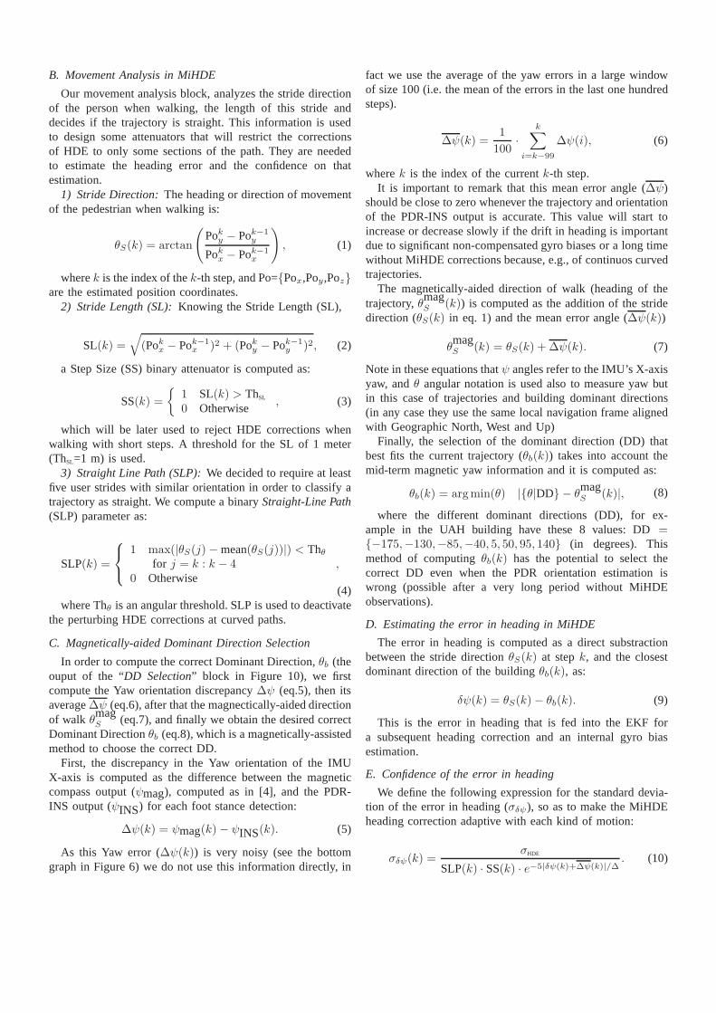
B. Movement Analysis in MiHDE
Our movement analysis block, analyzes the stride directionof the person when walking, the length of this stride anddecides if the trajectory is straight. This information is usedto design some attenuators that will restrict the correctionsof HDE to only some sections of the path. They are neededto estimate the heading error and the confidence on thatestimation.
1) Stride Direction:The heading or direction of movementof the pedestrian when walking is:
θS(k) = arctan
(
Poky − Pok−1y
Pokx − Pok−1x
)
, (1)
wherek is the index of thek-th step, and Po={Pox,Poy,Poz}are the estimated position coordinates.
2) Stride Length (SL):Knowing the Stride Length (SL),
SL(k) =√
(Pokx − Pok−1x )2 + (Poky − Pok−1
y )2, (2)
a Step Size (SS) binary attenuator is computed as:
SS(k) =
{
1 SL(k) > ThSL
0 Otherwise, (3)
which will be later used to reject HDE corrections whenwalking with short steps. A threshold for the SL of 1 meter(ThSL=1 m) is used.
3) Straight Line Path (SLP):We decided to require at leastfive user strides with similar orientation in order to classify atrajectory as straight. We compute a binaryStraight-Line Path(SLP) parameter as:
SLP(k) =
1 max(|θS(j)− mean(θS(j))|) < Thθfor j = k : k − 4
0 Otherwise,
(4)where Thθ is an angular threshold. SLP is used to deactivate
the perturbing HDE corrections at curved paths.
C. Magnetically-aided Dominant Direction Selection
In order to compute the correct Dominant Direction,θb (theouput of the “DD Selection” block in Figure 10), we firstcompute the Yaw orientation discrepancy∆ψ (eq.5), then itsaverage∆ψ (eq.6), after that the magnectically-aided directionof walk θmag
S (eq.7), and finally we obtain the desired correctDominant Directionθb (eq.8), which is a magnetically-assistedmethod to choose the correct DD.
First, the discrepancy in the Yaw orientation of the IMUX-axis is computed as the difference between the magneticcompass output (ψmag), computed as in [4], and the PDR-INS output (ψINS) for each foot stance detection:
∆ψ(k) = ψmag(k)− ψINS(k). (5)
As this Yaw error (∆ψ(k)) is very noisy (see the bottomgraph in Figure 6) we do not use this information directly, in
fact we use the average of the yaw errors in a large windowof size 100 (i.e. the mean of the errors in the last one hundredsteps).
∆ψ(k) =1
100·
k∑
i=k−99
∆ψ(i), (6)
wherek is the index of the currentk-th step.It is important to remark that this mean error angle (∆ψ)
should be close to zero whenever the trajectory and orientationof the PDR-INS output is accurate. This value will start toincrease or decrease slowly if the drift in heading is importantdue to significant non-compensated gyro biases or a long timewithout MiHDE corrections because, e.g., of continuos curvedtrajectories.
The magnetically-aided direction of walk (heading of thetrajectory,θmag
S (k)) is computed as the addition of the stridedirection (θS(k) in eq. 1) and the mean error angle (∆ψ(k))
θmagS (k) = θS(k) + ∆ψ(k). (7)
Note in these equations thatψ angles refer to the IMU’s X-axisyaw, andθ angular notation is used also to measure yaw butin this case of trajectories and building dominant directions(in any case they use the same local navigation frame alignedwith Geographic North, West and Up)
Finally, the selection of the dominant direction (DD) thatbest fits the current trajectory (θb(k)) takes into account themid-term magnetic yaw information and it is computed as:
θb(k) = argmin(θ) |{θ|DD} − θmagS (k)|, (8)
where the different dominant directions (DD), for ex-ample in the UAH building have these 8 values: DD={−175,−130,−85,−40, 5, 50, 95, 140} (in degrees). Thismethod of computingθb(k) has the potential to select thecorrect DD even when the PDR orientation estimation iswrong (possible after a very long period without MiHDEobservations).
D. Estimating the error in heading in MiHDE
The error in heading is computed as a direct substractionbetween the stride directionθS(k) at stepk, and the closestdominant direction of the buildingθb(k), as:
δψ(k) = θS(k)− θb(k). (9)
This is the error in heading that is fed into the EKF fora subsequent heading correction and an internal gyro biasestimation.
E. Confidence of the error in heading
We define the following expression for the standard devia-tion of the error in heading (σδψ), so as to make the MiHDEheading correction adaptive with each kind of motion:
σδψ(k) =σHDE
SLP(k) · SS(k) · e−5|δψ(k)+∆ψ(k)|/∆. (10)

The value of σHDE is selected as a trade-off to give areasonable confidence about the HDE-based yaw corrections,in our case is selected as 0.1 radians. The SS and SLP termsare the binary values computed in equations 3 and 4, they meanthat in case of a Straight Line Path with long-enough steps,then the heuristic is applied, otherwise it value is zero andtherefore theσδψ is infinite (no confidence), i.e. no MiHDEcorrection is applied. The exponential term (e−5|δψ+∆ψ/∆) isused to limit the correction from straight paths not too wellaligned with the building’s dominant directions. In summary,only straight well-aligned paths at a normal pace are basicallyused in MiHDE. This contrasts with the original HDE methodthat always applies corrections, even in curved trajectories,whenever the steps are long enough.
F. Additional gyro bias estimation support
In order to increase the observability of gyro biases duringwalk (note that Gyro biases are mainly well estimated duringStill periods with ZARU, but these updates are not frequentin practice), we added a block that increase or decrease thecurrent bias value whenever it is detected a systematic yawerror (e.g.δψ has a predominant sign). This method assumesthat if an almost perfect straight trajectory is systematicallycurved to the right or Clock Wise direction (CW drift), then thebias of the vertical gyroscope is over-estimated, and viceversatrajectories that curve to the left or Counter Clock Wisedirection (CCW drift) are caused by under-estimated biases.So in order to correct the bias, incremental small quantities areadded or subtracted to the current bias estimates to attenuatelong-term systematic drifts in heading.
δw(k) = δw(k)−+∆w ·sign{Rbn(k)− ∗ (0, 0, δψ(k))}, (11)
where∆w is an arbitrary constant that represents the smallquantities added or subtracted to the gyro biases. The termδw(k)− is the a priori gyro bias vector (3 components inx,y and z axis),Rbn(k)
− is the a priori rotation matrix thattransforms a vector from the navigation frame (Noth-West-Up)to the body sensor frame, and thesign function takes a +1 forpositive values, and -1 for negative ones. The confidence thatwe have on this correction is dependent on the confidence onthe yaw correction (σδψ, in eq. 10), so corrections in gyrosbiases are only activated when MiHDE is active (long steps,straight trajectories, paths aligned to dominant directions,...).
V. EXPERIMENTAL EVALUATION
For the evaluation of the proposed MiHDE method, andfor comparing it to the IEZ and HDE methods, we use both,synthetically generated IMU signal with a ground-truth, andalso real experiments performed at a building using a footmounted IMU.
A. Evaluation using a synthetically generated IMU signal witha ground-truth
We have employed several synthetically-generated IMUsignals using the methodology proposed in [12]. Each gen-erated IMU signal has a ground-truth of the position (as well
as attitude and velocity) for every sample in the simulatedtrajectory. The ideal IMU signal sampled at 100 Hz, wascontaminated with a known constant bias at the gyroscopes(0.01, 0.006 and 0.003 rad/s for axes x, y and z, respectively).All trajectories generated have an initial and final intervalwhere the IMU is motionless, in particular the simulationconsiders that the person (the foot) is still 10 seconds beforestarting to move, and also just after ending the trajectory foranother 10 seconds.
A square trajectory repeated twice was generated as an“easy” one satisfying very well the HDE assumptions (movingalong two principal directions: North-South or East-West;i.e.∆=90o). In this case the IEZ method is expected to accumulatedrift in heading, but HDE and MiHDE should clearly getadvantage of the dominant directions corrections to eliminatethe drift. Results are shown in Fig. 11.
We observe in Fig. 11a that the IEZ solution has some driftin yaw, as expected, however this drift is not so damagingsince the ZARU correction of IEZ during the initial 10seconds interval (first 1000 samples) allows the system topartially estimate the gyro biases. During the motion thereis no observability of yaw angle, so estimated biases do notimprove, although the uncertainly in the covariance matricesof estimates grows. The final still phase achieves the correctestimation of gyro biases. For the HDE method we observe inFig. 11b that yaw is observable and consequently the bias ofgyroscopes. After 100 s of walk (10.000 samples) biases arewell estimated. The 8 spikes in the bias plot corresponds tothe 8 turns that slightly perturbs the estimations. The MiHDEmethod performs similarly to HDE as can be seen in Fig. 11c,but in this case no perturbations appear since during turnsno corrections are applied. For this “ideal” type of trajectoriesboth HDE and MiHDE method perform quite well eliminatingthe drift in heading.
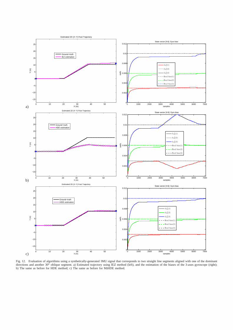
A more challenging trajectory for HDE is evaluated aspresented in Fig. 12. This trajectory consists of two straightline segments aligned with one of the dominant directions(west-east) at the beginning and end sections, and in themiddle a straight-line segment 30o degrees oblique from thedominant direction. The bias convergence in Fig. 12a for IEZis similar to the case presented before in Fig. 13a. The middlesegment is not correctly processed by HDE method, neither inthe position estimation nor in the bias estimation. In fact thebias is wrongly estimated during this oblique path (samplesfrom 2800 to 4400). When the path is again aligned withthe dominant direction (samples 4400 to 6100) the bias isprogressively recovered to the true value. The performanceofMiHDE is improved simply by ignoring the yaw correctionsduring the non-aligned sections of walk, under this case itbasically uses the previously computed biases.
Another challenging trajectory for HDE is evaluated aspresented in Fig. 13. This trajectory consists of two straightline segments aligned with one of the dominant directions(west-east) at the beginning and end sections, and in themiddle two iterations of a circular trajectory having a radiusof 10 meters. The IEZ performs as usual, it is basically

a)0 5 10 15 20
0
2
4
6
8
10
12
14
16
18
20
Estimated 2D (X−Y) Foot Trajectory
X (m)
Y (
m)
Ground−truthIEZ estimation
0 5000 10000 150000
0.002
0.004
0.006
0.008
0.01
0.012
samples
rad/
s
State vector [4:6]: Gyro bias
δωb
k(1)
δωb
k(2)
δωb
k(3)
Real bias(1)
Real bias(2)
Real bias(3)
b)0 5 10 15 20
0
2
4
6
8
10
12
14
16
18
20Estimated 2D (X−Y) Foot Trajectory
X (m)
Y (
m)
Ground−truthHDE estimation
0 5000 10000 150000
0.002
0.004
0.006
0.008
0.01
0.012
samples
rad/
s
State vector [4:6]: Gyro bias
δωb
k(1)
δωb
k(2)
δωb
k(3)
Real bias(1)
Real bias(2)
Real bias(3)
c)0 5 10 15 20
0
2
4
6
8
10
12
14
16
18
20Estimated 2D (X−Y) Foot Trajectory
X (m)
Y (
m)
Ground−truthiHDE estimation
0 5000 10000 150000
0.002
0.004
0.006
0.008
0.01
0.012
samples
rad/
s
State vector [4:6]: Gyro bias
δωb
k(1)
δωb
k(2)
δωb
k(3)
Real bias(1)
Real bias(2)
Real bias(3)
Fig. 11. Evaluation of algorithms using a synthetically-generated IMU signal that corresponds to a square trajectory repeated twice. a) Estimated trajectoryusing IEZ method (left), and the estimation of the biases of the 3-axes gyroscope (right); b) The same as before for HDE method; c) The same as before forMiHDE method.
a)0 10 20 30 40 50
−15
−10
−5
0
5
10
15
20
25
Estimated 2D (X−Y) Foot Trajectory
X (m)
Y (
m)
Ground−truthIEZ estimation
0 1000 2000 3000 4000 5000 6000 70000
0.002
0.004
0.006
0.008
0.01
0.012State vector [4:6]: Gyro bias
samples
rad/
s
δωb
k(1)
δωb
k(2)
δωb
k(3)
Real bias(1)
Real bias(2)
Real bias(3)
b)0 10 20 30 40 50
−15
−10
−5
0
5
10
15
20
25
Estimated 2D (X−Y) Foot Trajectory
X (m)
Y (
m)
Ground−truthHDE estimation
0 1000 2000 3000 4000 5000 6000 70000
0.002
0.004
0.006
0.008
0.01
0.012
samples
rad/
s
State vector [4:6]: Gyro bias
δωb
k(1)
δωb
k(2)
δωb
k(3)
Real bias(1)
Real bias(2)
Real bias(3)
c)0 10 20 30 40 50
−15
−10
−5
0
5
10
15
20
25
Estimated 2D (X−Y) Foot Trajectory
X (m)
Y (
m)
Ground−truthiHDE estimation
0 1000 2000 3000 4000 5000 6000 70000
0.002
0.004
0.006
0.008
0.01
0.012
samples
rad/
s
State vector [4:6]: Gyro bias
δωb
k(1)
δωb
k(2)
δωb
k(3)
Real bias(1)
Real bias(2)
Real bias(3)
Fig. 12. Evaluation of algorithms using a synthetically-generated IMU signal that corresponds to two straight line segments aligned with one of the dominantdirections and another 30o oblique segment. a) Estimated trajectory using IEZ method (left), and the estimation of the biases of the 3-axes gyroscope (right);b) The same as before for HDE method; c) The same as before for MiHDE method.

not dependent on the kind of trajectory, as it is observed inFig. 13a. The degradation expected for HDE can be visualizedin Fig. 13b, there is a deformation of the circular path shapeand an error in the heading. This is caused by the alternativecorrections in yaw on each two dominant directions (horizontaland vertical). The eight peaks in the bias estimations duringthe 2 circular paths corresponds to the 4 damaging correctionalong the directions in a single cycle: North-South, West-East,South-North, East-West. MiHDE on the contrary deactivatescorrections during the circular path and consequently onlyaccumulates a drift in heading similar to that of IEZ, but thepositioning and heading error is corrected when walking againalong a straight path at the end of the trajectory (see Fig. 13c).
B. Evaluation using Real IMU signals recorded in a complexbuilding
Several tests were performed using a foot-mounted IMU(XSens Inc.) at the building shown in Fig.?? (∆ =45o).
1) Wide slightly-curved corridors:In the first floor of thisbuilding, there are wide curved corridors (see Fig.14a). Wetested the HDE and the proposed MiHDE algorithms in thesechallenging conditions. The positioning results for a closed460-meters-long path is shown in Fig.14b and c. The damagingaction of HDE is perceived mainly in the curved path in theeast wing. MiHDE basically does not apply corrections oncurves and achieves a slightly lower positioning error thanHDE.
2) Circular Paths: Other results for circular paths arepresented in Fig. 15. The damaging effect of HDE causesa position and orientation error when finishing the circularloops (e.g. after the 4 loops in Fig. 15 just before returningstraight to the starting point). Other tests performed confirmedimprovements of the MiHDE method over the HDE for routesincluding difficult trajectories (improvements of about 0.2%of TTD). In more “ideal” floors having long narrow corridors(like the third floor in Fig.2), the performance of HDE andMiHDE is quite similar, as expected.
C. Evaluating the capability to avoid false dominant directionassignments
In order to explore the capabilities of the MiHDE methodto escape from false dominant direction matches, we haveperformed some trajectories that include very long circularpaths. The idea is to let the PDR algorithm work withoutDD correction during a long time in order to accumulate asignificant drift in heading. An accumulated heading errorlarger than 22.5 degrees will be enough to cause a wrongdominant direction match in HDE and iHDE methods. Withthis kind of trajectories we should observe how the MiHDE is,on the contrary, able to detect this wrong situation and finallyalign with the true dominant direction.
We show in Figure 16 how the basic IEZ method accumu-lates a progressive drift in heading, as well as the HDE andiHDE algorithms perform well until the estimation reachesthe region with the 20 consecutive circles. At the end ofthis repetitive circular path the orientation of HDE and iHDE
a)
North
Start/Endpoint
HDE
b)
North
iHDE
Start/Endpoint
c)
Fig. 14. Tests in a floor with wide and curved corridors. a) Photo of thecorridor, b) Estimation with HDE, c) Estimation with MiHDE.The black smallcircles in the path mark the HDE or MiHDE heading corrections. The size ofthese circles is inversely proportional toσδψ . HDE is making correctionsall the time with a constantσδψ = σHDE/SS, however MiHDE correctsadaptively, mainly at well-aligned straight-line segments, using eq. 10.

a)0 5 10 15 20 25 30 35 40
−10
−5
0
5
10
Estimated 2D (X−Y) Foot Trajectory
X (m)
Y (
m)
Grounth−truthIEZ estimation
0 2000 4000 6000 8000 10000 12000 14000 160000
0.002
0.004
0.006
0.008
0.01
0.012
samples
rad/
s
State vector [4:6]: Gyro bias
δωb
k(1)
δωb
k(2)
δωb
k(3)
Real bias(1)
Real bias(2)
Real bias(3)
b)0 5 10 15 20 25 30 35 40
−10
−5
0
5
10
Estimated 2D (X−Y) Foot Trajectory
X (m)
Y (
m)
Grounth−truthHDE estimation
0 2000 4000 6000 8000 10000 12000 14000 16000−2
0
2
4
6
8
10
12
14
16x 10
−3
samples
rad/
s
State vector [4:6]: Gyro bias
δωb
k(1)
δωb
k(2)
δωb
k(3)
Real bias(1)
Real bias(2)
Real bias(3)
c)0 5 10 15 20 25 30 35 40
−10
−5
0
5
10
Estimated 2D (X−Y) Foot Trajectory
X (m)
Y (
m)
Grounth−truthiHDE estimation
0 2000 4000 6000 8000 10000 12000 14000 160000
0.002
0.004
0.006
0.008
0.01
0.012
samples
rad/
s
State vector [4:6]: Gyro bias
δωb
k(1)
δωb
k(2)
δωb
k(3)
Real bias(1)
Real bias(2)
Real bias(3)
Fig. 13. Evaluation of algorithms using a synthetically-generated IMU signal that corresponds to two straight line segments aligned with one of the dominantdirections and 2 circular paths in between having a radius of10 meters. a) Estimated trajectory using IEZ method (left),and the estimation of the biases ofthe 3-axes gyroscope (right); b) The same as before for HDE method; c) The same as before for MiHDE method.

NorthStart/Endpoint
HDE
a)
Start/Endpoint
North
iHDE
b)
Fig. 15. Test walking around a circular path 4 times (the starting and finalpath is straight at a 45o dominant direction). a) HDE estimation, b) MiHDEestimation. The total route length is 146 m.
algorithms is bad enough to be matched to a wrong dominantdirection (the horizontal DD). We observe, however, thatthe MiHDE algorithm presented in this paper accumulates asimilar bad alignment at the end of the circular paths, but itis able to distinguish the right dominant direction among theeight ones available. Therefore, the estimation is much betterthan in the other approaches.
VI. CONCLUSION
We have analyzed the limitations of the HDE method,proposed a improved version (MiHDE), and tested both inchallenging buildings. We confirm that the heuristic that usesthe dominant’s directions of the building is an extraordinarymethod to implement practical PDR indoor navigation solu-tions (with none or a minimum infrastructure), and it is a greatalternative to pure compass-based navigation when magneticdisturbances are significant. We have demonstrated that even
with severe magnetic perturbations a mid-term absolute head-ing correction is possible, so we put together the benefits fromdominant directions in a building and the statistical zero-meanbehavior of the magnetically-estimated heading.
ACKNOWLEDGMENT
The authors thank the financial support from projectsLEMUR (TIN2009-14114-C04-03) and LAZARO (CSIC-PIERef.201150E039). Special thanks to J. Urena and J.C. Garc´ıafrom the Electronics Department of UAH for their help.
REFERENCES
[1] J. Borenstein and L. Ojeda, “Heuristic Drift Elimination for PersonnelTracking Systems,”Journal of Navigation, vol. 63, pp. 591–606, Sept.2010.
[2] K. Abdulrahim, C. Hide, T. Moore, and C. Hill, “Aiding MEMS IMUwith building heading for indoor pedestrian navigation,” in UbiquitousPositioning Indoor Navigation and Location Based Service (UPINLBS),2010, pp. 1–6, IEEE, 2010.
[3] E. Foxlin, “Pedestrian tracking with shoe-mounted inertial sensors,”IEEE Computer Graphics and Applications, no. December, pp. 38–46,2005.
[4] A. Jimenez, F. Seco, J. Prieto, and J. Guevara, “Indoor PedestrianNavigation using an INS/EKF framework for Yaw Drift Reduction anda Foot-mounted IMU,” inWPNC 2010: 7th Workshop on Positioning,Navigation and Communication, Dresden (Germany), vol. 10, pp. 135–143, 2010.
[5] V. Renaudin, M. Afzal, and G, “New method for magnetometers basedorientation estimation,” inPosition Location And Navigation Symposium,Indian Wells/Palm Springs, California USA, p. 9, 2010.
[6] M. H. Afzal, V. Renaudin, and G. Lachapelle, “Use of Earth’sMagnetic Field for Mitigating Gyroscope Errors Regardlessof MagneticPerturbation,”Sensors, vol. 11(12), pp. 11390–11414, 2011.
[7] C. C. Finlay, S. Maus, C. D. Beggan, T. N. Bondar, A. Chambodut,T. a. Chernova, A. Chulliat, V. P. Golovkov, B. Hamilton, M. Hamoudi,R. Holme, G. Hulot, W. Kuang, B. Langlais, V. Lesur, F. J. Lowes,H. Luhr, S. Macmillan, M. Mandea, S. McLean, C. Manoj, M. Men-vielle, I. Michaelis, N. Olsen, J. Rauberg, M. Rother, T. J. Sabaka,A. Tangborn, L. Tø ffner Clausen, E. Thebault, a. W. P. Thomson,I. Wardinski, Z. Wei, and T. I. Zvereva, “International GeomagneticReference Field: the eleventh generation,”Geophysical Journal Interna-tional, vol. 183, pp. 1216–1230, Dec. 2010.
[8] P. Aggarwal, D. Thomas, L. Ojeda, and J. Borenstein, “Mapmatchingand heuristic elimination of gyro drift for personal navigation systems inGPS-denied conditions,”Measurement Science and Technology, vol. 22,p. 025205, Feb. 2011.
[9] A. Jimenez, F. Seco Granja, J. C. Prieto Honorato, and J.GuevaraRosas, “Accurate Pedestrian Indoor Navigation by Tightly Coupling aFoot-mounted IMU and RFID Measurements,”IEEE Transactions onInstrumentation and Measurement, vol. 61, no. 1, pp. 178 – 189, 2011.
[10] J. Hightower and G. Borriello, “Location Systems for UbiquitousComputing,”Computer, vol. 34, no. 8, pp. 57 – 66, 2001.
[11] A. Jimenez, F. Seco, F. Zampella, J. C. Prieto, and J. Guevara, “ImprovedHeuristic Drift Elimination ( iHDE ) for Pedestrian Navigation inComplex Buildings,” inIPIN, no. September, pp. 21–23, 2011.
[12] F. J. Zampella, A. R. Jimenez, F. Seco, J. C. Prieto, andJ. I. Guevara,“Simulation of Foot-Mounted IMU Signals for the Evaluationof PDRAlgorithms,” in International Conference on Indoor Positioning andIndoor Navigation (IPIN), no. September, pp. 21–23, 2011.

a) b)
c) d)
Fig. 16. Trajectory with a long circular path repeated 20 times (at right-bottom floormap) in order to test the magnetically-aided dominant direction correctionof MiHDE. a) Results for IEZ, b) HDE estimation, c) iHDE estimation, and d) MiHDE estimation.