important carefully read and understand this … 835 / 1135 / 1335 st3b manitou bf s.a limited...
TRANSCRIPT
IMPORTANT
Carefully read and understand this instruction manual before using the lift truck.
It contains all information relating to operation, handling and lift truck equipment,
as well as important recommendations to be followed.
This document also contains precautions for use, as well as information on the servicing and routine maintenance required
to ensure the lift truck's continued safety of use and reliability.
WHENEVER YOU SEE THIS SYMBOL IT MEANS: IMPORTANT
WARNING ! BE CAREFUL ! YOUR SAFETY OR THE SAFETY OF THE LIFT TRUCK IS AT RISK. - This manual has been produced on the basis of the equipment list and the technical characteristics
given at the time of its design.
- The level of equipment of the lift truck depends on the options chosen and the country of sale.
- According to the lift truck options and the date of sale, certain items of equipment/functions described
herein may not be available.
- Descriptions and figures are non binding.
- MANITOU reserves the right to change its models and their equipment without being required to
update this manual.
- The MANITOU network, consisting exclusively of qualified professionals, is at your disposal to answer
all your questions.
- This manual is an integral part of the lift truck.
- It is to be kept in its storage space at all times for ease of reference.
- Hand this manual to the new owner if the lift truck is resold.
6471
04 (1
3/06
/201
6)
MT 83
5 / 11
35 / 1
335
ST3B

Manitou BF S.A Limited liability company with a Board of Directors.
Head office: 430, Rue de l’Aubinière - 44150 Ancenis - FRANCE
Share capital: 39,548,949 euros
857 802 508 RCS Nantes.
Tel: +33 (0)2 40 09 10 11
www.manitou.com
This manual is for information purposes only. Any reproduction, copy, representation, recording, transfer, distribution, or other, in part
or in whole, in any format is prohibited. The plans, designs, views, commentaries and instructions, even the document organization
that are found in this document, are the intellectual property of MANITOU BF. Any violation of the aforementioned may lead to civil
and criminal prosecution. The logos as well as the visual identity of the company are the property of MANITOU BF and may not be
used without express and formal authorization. All rights are reserved.
21/05/2012
22/02/2013 + MT 835 ST3B + MT 1135 ST3B
24/06/2013 1-9 2-8 ; 2-41 ; 2-48 ; 2-50
16/09/2013 2-6 ; 2-8 ; 2-12 ; 2-13 ; 2-15 ; 2-17 ; 2-70 ; 2-71 3-10
18/06/2014 4-5 ; 4-8 - 4-14
13/06/2016 1-3 ; 1-7 ; 1-9 ; 1-21 ; 1-24 ; 1-26 2-8 ; 2-9 ; 2-20 ; 2-47 ; 2-48 ; 2-49 ; 2-51 ; 2-68 3-5 – 3-9 ; 3-20 ; 3-26 – 3-29
UPDATED
1st ISSUE
6471
04 (1
3/06
/201
6)
MT 83
5 / 11
35 / 1
335
ST3B
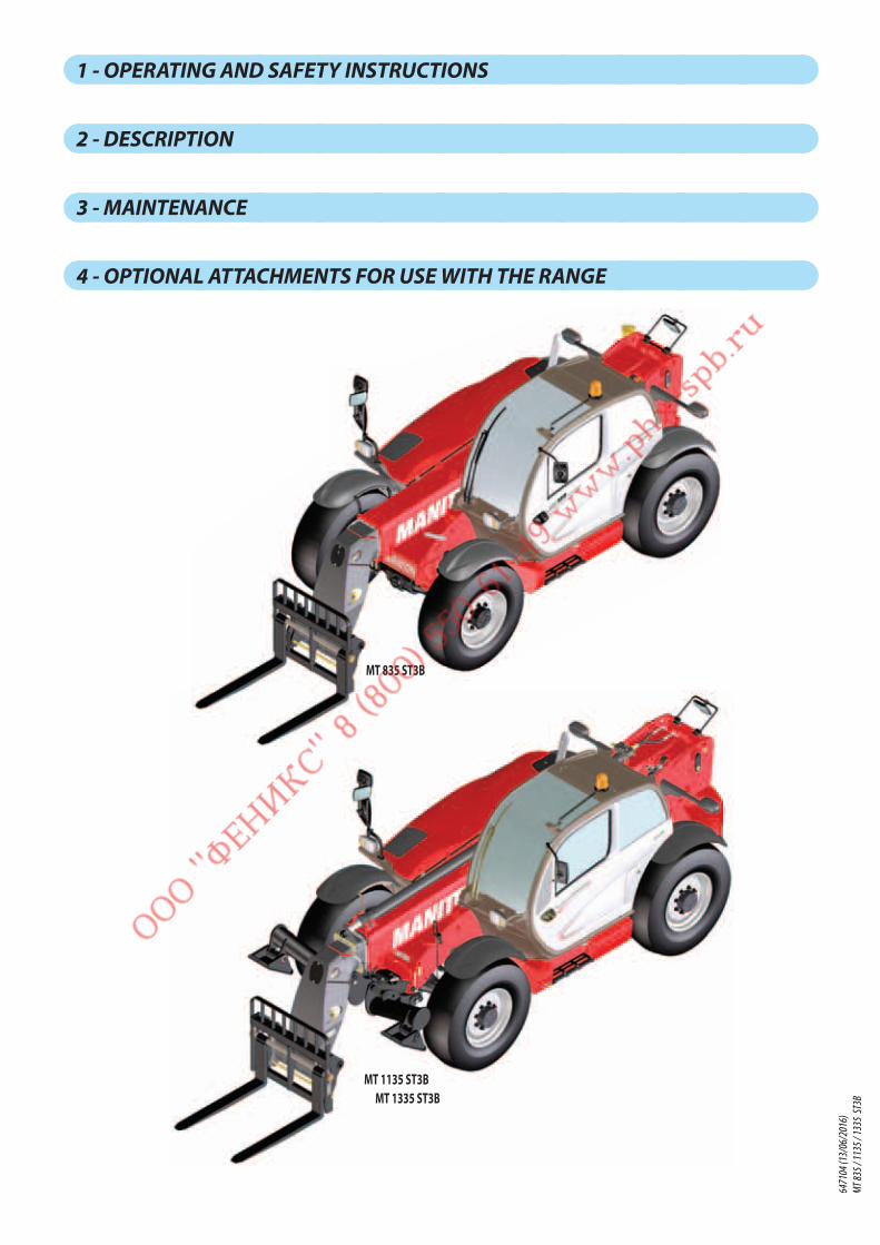
1 - OPERATING AND SAFETY INSTRUCTIONS
2 - DESCRIPTION
3 - MAINTENANCE
4 - OPTIONAL ATTACHMENTS FOR USE WITH THE RANGE
MT 835 ST3B
MT 1135 ST3BMT 1335 ST3B
6471
04 (1
3/06
/201
6)
MT 83
5 / 11
35 / 1
335
ST3B

1 - 1
1 - OPERATING
AND SAFETY
INSTRUCTIONS
6471
04 (1
3/06
/201
6)
MT 83
5 / 11
35 / 1
335
ST3B

1 - 2
6471
04 (1
3/06
/201
6)
MT 83
5 / 11
35 / 1
335
ST3B

1 - 3
6471
04 (1
3/06
/201
6)
MT 83
5 / 11
35 / 1
335
ST3B
1 - 4
TABLE OF CONTENTS
1 - OPERATING AND SAFETY INSTRUCTIONS
INSTRUCTIONS TO THE COMPANY MANAGER 6
THE SITE 6
THE OPERATOR 6
THE LIFT TRUCK 6A - THE TRUCK'S SUITABILITY FOR THE JOB . . . . . . . . . . . . . . . . . . . . . . . . . . . . . . . . . . . . . . . . . . . . . . 6
B - ADAPTATION OF THE LIFT TRUCK TO STANDARD ENVIRONMENTAL CONDITIONS . . . . . . . . . . . . . . . . . . . . 6
C - MODIFICATION OF THE LIFT TRUCK . . . . . . . . . . . . . . . . . . . . . . . . . . . . . . . . . . . . . . . . . . . . . . . . . 7
D - FRENCH ROAD TRAFFIC RULES . . . . . . . . . . . . . . . . . . . . . . . . . . . . . . . . . . . . . . . . . . . . . . . . . . . . 7
E - LIFT TRUCK CAB PROTECTION. . . . . . . . . . . . . . . . . . . . . . . . . . . . . . . . . . . . . . . . . . . . . . . . . . . . . 7
THE INSTRUCTIONS 7
THE MAINTENANCE 7
INSTRUCTIONS FOR THE OPERATOR 8
PREAMBLE 8
GENERAL INSTRUCTIONS 8A - OPERATOR'S MANUAL . . . . . . . . . . . . . . . . . . . . . . . . . . . . . . . . . . . . . . . . . . . . . . . . . . . . . . . . . 8
B - AUTHORISATION FOR USE IN FRANCE . . . . . . . . . . . . . . . . . . . . . . . . . . . . . . . . . . . . . . . . . . . . . . . 8
C - MAINTENANCE . . . . . . . . . . . . . . . . . . . . . . . . . . . . . . . . . . . . . . . . . . . . . . . . . . . . . . . . . . . . . . 8
D - MODIFICATION OF THE LIFT TRUCK . . . . . . . . . . . . . . . . . . . . . . . . . . . . . . . . . . . . . . . . . . . . . . . . . 8
E - LIFTING PEOPLE . . . . . . . . . . . . . . . . . . . . . . . . . . . . . . . . . . . . . . . . . . . . . . . . . . . . . . . . . . . . . 9
OPERATING INSTRUCTIONS UNLADEN AND LADEN 9A - BEFORE STARTING THE LIFT TRUCK . . . . . . . . . . . . . . . . . . . . . . . . . . . . . . . . . . . . . . . . . . . . . . . . . 9
B - DRIVER'S OPERATING INSTRUCTIONS . . . . . . . . . . . . . . . . . . . . . . . . . . . . . . . . . . . . . . . . . . . . . . . . 9
C - ENVIRONMENT . . . . . . . . . . . . . . . . . . . . . . . . . . . . . . . . . . . . . . . . . . . . . . . . . . . . . . . . . . . . . . 9
D - VISIBILITY . . . . . . . . . . . . . . . . . . . . . . . . . . . . . . . . . . . . . . . . . . . . . . . . . . . . . . . . . . . . . . . . 10
E - STARTING THE LIFT TRUCK . . . . . . . . . . . . . . . . . . . . . . . . . . . . . . . . . . . . . . . . . . . . . . . . . . . . . . 11
F - DRIVING THE LIFT TRUCK . . . . . . . . . . . . . . . . . . . . . . . . . . . . . . . . . . . . . . . . . . . . . . . . . . . . . . . 11
G - STOPPING THE LIFT TRUCK . . . . . . . . . . . . . . . . . . . . . . . . . . . . . . . . . . . . . . . . . . . . . . . . . . . . . 12
H - DRIVING THE LIFT TRUCK ON THE PUBLIC HIGHWAY . . . . . . . . . . . . . . . . . . . . . . . . . . . . . . . . . . . . . 13
INSTRUCTIONS FOR HANDLING A LOAD 14A - CHOICE OF ATTACHMENTS . . . . . . . . . . . . . . . . . . . . . . . . . . . . . . . . . . . . . . . . . . . . . . . . . . . . . 14
B - MASS OF LOAD AND CENTRE OF GRAVITY. . . . . . . . . . . . . . . . . . . . . . . . . . . . . . . . . . . . . . . . . . . . 14
C - LONGITUDINAL STABILITY LIMITER AND WARNING DEVICE . . . . . . . . . . . . . . . . . . . . . . . . . . . . . . . . . 14
D - TRANSVERSE ATTITUDE OF THE LIFT TRUCK. . . . . . . . . . . . . . . . . . . . . . . . . . . . . . . . . . . . . . . . . . . 15
E - TAKING UP A LOAD ON THE GROUND. . . . . . . . . . . . . . . . . . . . . . . . . . . . . . . . . . . . . . . . . . . . . . . 15
F - TAKING UP AND LAYING A HIGH LOAD ON TYRES . . . . . . . . . . . . . . . . . . . . . . . . . . . . . . . . . . . . . . . 16
G - TAKING UP AND LAYING A HIGH LOAD ON STABILIZERS . . . . . . . . . . . . . . . . . . . . . . . . . . . . . . . . . . . 18
H - TAKING UP AND LAYING DOWN A SUSPENDED LOAD . . . . . . . . . . . . . . . . . . . . . . . . . . . . . . . . . . . . 20
I - TRAVELLING WITH A SUSPENDED LOAD. . . . . . . . . . . . . . . . . . . . . . . . . . . . . . . . . . . . . . . . . . . . . . 20
PLATFORM OPERATING INSTRUCTIONS 21A - AUTHORISATION FOR USE . . . . . . . . . . . . . . . . . . . . . . . . . . . . . . . . . . . . . . . . . . . . . . . . . . . . . . 21
B - LIFT TRUCK SUITABILITY FOR USE . . . . . . . . . . . . . . . . . . . . . . . . . . . . . . . . . . . . . . . . . . . . . . . . . 21
C - PRECAUTIONS WHEN USING THE PLATFORM . . . . . . . . . . . . . . . . . . . . . . . . . . . . . . . . . . . . . . . . . . 21
D - USING THE PLATFORM . . . . . . . . . . . . . . . . . . . . . . . . . . . . . . . . . . . . . . . . . . . . . . . . . . . . . . . . 21
E - ENVIRONMENT . . . . . . . . . . . . . . . . . . . . . . . . . . . . . . . . . . . . . . . . . . . . . . . . . . . . . . . . . . . . . 21
F - MAINTENANCE . . . . . . . . . . . . . . . . . . . . . . . . . . . . . . . . . . . . . . . . . . . . . . . . . . . . . . . . . . . . . 22
INSTRUCTIONS FOR USING THE RADIO-CONTROL 23HOW TO USE THE RADIO-CONTROL . . . . . . . . . . . . . . . . . . . . . . . . . . . . . . . . . . . . . . . . . . . . . . . . . . 23
PROTECTIVE DEVICES . . . . . . . . . . . . . . . . . . . . . . . . . . . . . . . . . . . . . . . . . . . . . . . . . . . . . . . . . . . 23
6471
04 (1
3/06
/201
6)
MT 83
5 / 11
35 / 1
335
ST3B
1 - 5
LIFT TRUCK MAINTENANCE INSTRUCTIONS 24
GENERAL INSTRUCTIONS 24
PLACING THE JIB SAFETY WEDGE 24FITTING THE WEDGE. . . . . . . . . . . . . . . . . . . . . . . . . . . . . . . . . . . . . . . . . . . . . . . . . . . . . . . . . . . . 24
REMOVING THE WEDGE . . . . . . . . . . . . . . . . . . . . . . . . . . . . . . . . . . . . . . . . . . . . . . . . . . . . . . . . . 24
MAINTENANCE 24MAINTENANCE LOGBOOK . . . . . . . . . . . . . . . . . . . . . . . . . . . . . . . . . . . . . . . . . . . . . . . . . . . . . . . . 24
LUBRICANT AND FUEL LEVELS 25
HYDRAULIC 25
ELECTRICITY 25
WELDING 25
WASHING THE LIFT TRUCK 25
TRANSPORTING THE LIFT TRUCK 25
IF THE LIFT TRUCK IS NOT TO BE USED FOR A LONG TIME 26
INTRODUCTION 26
PREPARING THE LIFT TRUCK 26
PROTECTING THE ENGINE 26
PROTECTING THE LIFT TRUCK 26
BRINGING THE LIFT TRUCK BACK INTO SERVICE 26
LIFT TRUCK DISPOSAL 27
RECYCLING OF MATERIALS 27METALS. . . . . . . . . . . . . . . . . . . . . . . . . . . . . . . . . . . . . . . . . . . . . . . . . . . . . . . . . . . . . . . . . . . . 27
PLASTICS. . . . . . . . . . . . . . . . . . . . . . . . . . . . . . . . . . . . . . . . . . . . . . . . . . . . . . . . . . . . . . . . . . . 27
RUBBER. . . . . . . . . . . . . . . . . . . . . . . . . . . . . . . . . . . . . . . . . . . . . . . . . . . . . . . . . . . . . . . . . . . . 27
GLASS. . . . . . . . . . . . . . . . . . . . . . . . . . . . . . . . . . . . . . . . . . . . . . . . . . . . . . . . . . . . . . . . . . . . . 27
ENVIRONMENTAL PROTECTION 27WORN OR DAMAGED PARTS . . . . . . . . . . . . . . . . . . . . . . . . . . . . . . . . . . . . . . . . . . . . . . . . . . . . . . 27
USED OIL . . . . . . . . . . . . . . . . . . . . . . . . . . . . . . . . . . . . . . . . . . . . . . . . . . . . . . . . . . . . . . . . . . . 27
USED BATTERIES . . . . . . . . . . . . . . . . . . . . . . . . . . . . . . . . . . . . . . . . . . . . . . . . . . . . . . . . . . . . . . 27
6471
04 (1
3/06
/201
6)
MT 83
5 / 11
35 / 1
335
ST3B

1 - 6
INSTRUCTIONS TO THE COMPANY MANAGER
THE SITE
Proper management of lift truck's area of travel will reduce the risk of accidents:
• ground not unnecessarily uneven or obstructed,
• no excessive slopes,
• pedestrian traffic controlled, etc.
THE OPERATOR
- Only qualified, authorized personnel can use the lift truck. This authorization is given in writing by the appropriate person
in the establishment with respect to the use of lift trucks and must be carried permanently by the operator.
IMPORTANT
Experience has shown that there are a number of inappropriate ways in which the lift truck might be used. Such foreseeable misuse, of which the main examples are listed
below, are strictly forbidden.
- The foreseeable abnormal behaviour resulting from ordinary negligence, but which does not result from any wish to put the machinery to any improper use.
- The reflex reactions of a person in the event of a malfunction, incident, fault, etc. during operation of the lift truck.
- Behaviour resulting from application of the "principle of least effort" when performing a task.
- For certain machines, the foreseeable behaviour of such persons as: apprentices, teenagers, handicapped persons, trainees tempted to drive a lift truck,
operators tempted to operate a truck for the purposes of a bet, a competition or for their own personal experience.
The person in charge of the equipment must take these criteria into account when assessing the suitability of a person to drive.
THE LIFT TRUCK
A - THE TRUCK'S SUITABILITY FOR THE JOB - MANITOU has ensured that this lift truck is suitable for use under the standard operating conditions defined in this
operator's manual, with a STATIC test coefficient OF 1,33 and a DYNAMIC test coefficient OF 1, as specified in harmonised
standard EN 1459 for variable range trucks.
- Before commissioning, the company manager must make sure that the lift truck is appropriate for the work to be done,
and perform certain tests (in accordance with current legislation).
B - ADAPTATION OF THE LIFT TRUCK TO STANDARD ENVIRONMENTAL CONDITIONS - In addition to series equipment mounted on your lift truck, many options are available, such as: road lighting, stop lights,
revolving light, reverse lights, reverse buzzer alarm, front light, rear light, light at the jib head, etc. (according to the lift
truck model).
- The operator must take into account the operating conditions to define the lift truck's signalling and lighting equipment.
Contact your dealer.
- Take into account climatic and atmospheric conditions of the site of utilisation.
• Protection against frost (see: 3 - MAINTENANCE: LUBRICANTS AND FUEL).
• Adaptation of lubricants (ask your dealer for information).
• Engine filtration (see: 3 - MAINTENANCE: FILTERS CARTRIDGES AND BELTS).
IMPORTANT
For operation under average climatic conditions, i.e.: between -15 °C and +35 °C, correct levels of lubricants in all the circuits are checked in production.
For operation under more severe climatic conditions, before starting up, it is necessary to drain all the circuits, then ensure correct levels of lubricants using lubricants
properly suited to the relevant ambient temperatures.
The same applies to the cooling liquid.
- A lift truck operating in an area without fire extinguishing equipment must be equipped with an individual extinguisher.
There are solutions, consult your dealer.
IMPORTANT
Your lift truck is designed for outdoor use under normal atmospheric conditions and indoor use in suitably aerated and ventilated premises.
It is prohibited to use the lift truck in areas where there is a risk of fire or which are potentially explosive
(e.g. Refineries, fuel or gas depots, stores of flammable products, etc.).
For use in these areas, specific equipment is available (ask your dealer for information).
- Our trucks comply with Directive 2004/108/EC concerning electromagnetic compatibility (EMC), and with the corresponding
harmonized standard EN 12895. Their proper operation is no longer guaranteed if they are used within areas in which
the electromagnetic fields exceed the limit specified by that standard (10 V/m).
- Directive 2002/44/EC requires company managers to not expose their employees to excessive vibration doses. There is
no recognized code of measurement for comparing the machines of different manufacturers. The actual doses received
cannot therefore be measured under actual operating conditions at the user's premises.
- The following are some tips for minimizing these vibration doses:
• Select the most suitable lift truck and attachment for the intended use.
6471
04 (1
3/06
/201
6)
MT 83
5 / 11
35 / 1
335
ST3B

1 - 7
• Adapt the seat adjustment to the operator's weight (according to lift truck model) and maintain it in good condition,
as well as the cab suspension. Inflate the tires in accordance with recommendations.
• Ensure that the operators adapt their operating speed to suit the conditions on site.
• As far as possible, arrange the site in such a way as to provide a flat running surface and remove obstacles and harmful
potholes.
C - MODIFICATION OF THE LIFT TRUCK - For your safety and that of others, you must not change the structure and settings of the various components used in your
lift truck (hydraulic pressure, calibrating limiters, engine speed, addition of extra equipment, addition of counterweight,
unapproved attachments, alarm systems, etc.) yourself. In this event, the manufacturer cannot be held responsible.
D - FRENCH ROAD TRAFFIC RULES(or see current legislation in other countries)
- Only one certificate of conformity is issued. It must be kept in a safe place.
- The driving of non EC type-approved tractors on the public highway is subject to the provisions of the highway code
relating to special machines, defined in article R311-1 of the highway code, in category B of the Equipment Order of
20 November 1969 that determines the procedures applicable to special machines. The lift truck must be fitted with a
licence plate.
- The driving of EC type-approved tractors on the public highway is subject to the provisions of the highway code regarding
agricultural tractors, defined in article R311-1 of the highway code. The lift truck must be registered.
SPECIAL INSTRUCTION APPLYING TO "EC TRACTOR" TYPE-APPROVED LIFT TRUCKS
- All EC tractor type-approved lift trucks are supplied with an "EC tractor" certificate complying with directive 2003/37/EC, to be retained by the owner, and a page of
administrative details together with a CNIT number (national type approval code) for registration at the prefecture.
- The lift truck owner is responsible for carrying out the necessary procedures for obtaining the vehicle registration document within the time limit defined by the regulations.
- The operator must hold an HGV licence, unless granted an exemption.
- The lift truck must be driven on the public highway in accordance with the instructions given in the manual supplied with the lift truck (Gross weight, Gross combination
weight, towing load, axle loads, maximum speeds, etc. according to type/version). The operator must be in possession of the lift truck’s registration document.
IMPORTANT
When towing a trailer or agricultural equipment, the travelling speed of the lift truck is limited to 25 km/h.
In this case, a "25" disc must be affixed to the rear of the convoy.
E - LIFT TRUCK CAB PROTECTION - All lift trucks comply with the requirements of ISO 3471 (wheel loader code) regarding cab rollover protection (ROPS)
and ISO 3449 (Level II) regarding the protection of the cab against falling objects (FOPS).
- "EC TRACTOR" type-approved lift trucks comply, in addition, with Directive 79/622/EC (OECD Code 4) regarding cab
rollover protection (ROPS).
IMPORTANT
Structural damage or overturning, a modification, changes or a poorly executed repair can reduce the protective efficiency of the cab, cancelling its compliance.
Do not perform welding or drilling on the cab structure.
Consult your dealer to determine the limits of this structure without cancelling its compliance.
THE INSTRUCTIONS
- The operator's manual must always be in good condition and kept in the place provided on the lift truck and in the
language used by the operator.
- The operator's manual and any plates or stickers which are no longer legible or are damaged, must be replaced immediately.
THE MAINTENANCE
- Maintenance or repairs other than those detailed in part: 3 - MAINTENANCE must be carried out by qualified personnel
(consult your dealer) and under the necessary safety conditions to maintain the health of the operator and any third party.
IMPORTANT
Your lift truck must be inspected periodically to ensure that it remains in compliance.
The frequency of this inspection is defined by current legislation in the country in which the lift truck is used.
- Example for France "The manager in charge of the establishment using a lift truck must open and maintain a maintenance
log for each machine (order of 2 March 2004) and undergo a general periodic inspection every 6 months (order of 1
March 2004)".
6471
04 (1
3/06
/201
6)
MT 83
5 / 11
35 / 1
335
ST3B

1 - 8
INSTRUCTIONS FOR THE OPERATOR
PREAMBLE
IMPORTANT
The risk of accident while using, servicing or repairing your lift truck can be restricted if you follow the safety instructions and safety measures detailed in these instruction.
Failure to respect the safety and operating instructions, or the instructions for repairing or servicing your lift truck may lead to serious, even fatal accident.
- Only the operations and manoeuvres described in these operator's manual must be performed. The manufacturer cannot
predict all possible risky situations. Consequently, the safety instructions given in the operator's manual and on the lift
truck itself are not exhaustive.
- At any time, as an operator, you must envisage, within reason, the possible risk to yourself, to others or to the lift truck
itself when you use it.
IMPORTANT
In order to reduce or avoid any danger with a MANITOU-approved attachment, follow the instructions of paragraph:
4 - ADAPTABLE ATTACHMENTS IN OPTION ON THE RANGE: INTRODUCTION.
GENERAL INSTRUCTIONS
A - OPERATOR'S MANUAL - Read the operator's manual carefully.
- The operator's manual must always be in good condition and in the place provided for it on the lift truck.
- You must report any plates and stickers which are no longer legible or which are damaged.
B - AUTHORISATION FOR USE IN FRANCE(or see current legislation in other countries).
- Only qualified, authorized personnel can use the lift truck. This authorization is given in writing by the appropriate person
in the establishment with respect to the use of lift trucks and must be carried permanently by the operator.
- The operator is not competent to authorise the driving of the lift truck by another person.
C - MAINTENANCE - The operator must immediately advise his superior if his lift truck is not in good working order or does not comply with
the safety notice.
- The operator is prohibited from carrying out any repairs or adjustments himself, unless he has been trained for this
purpose. He must keep the lift truck properly cleaned if this is among his responsibilities.
- The operator must carry out daily maintenance (see: 3 - MAINTENANCE: A - DAILY OR EVERY 10 HOURS SERVICE).
- The operator must ensure tyres are adapted to the nature of the ground (see area of the contact surface of the tyres in
the chapter: 2 - DESCRIPTION: TYRES). There are optional solutions, consult your dealer.
• SAND tyres.
• LAND tyres.
• Snow chains.
IMPORTANT
Do not use the lift truck if the tyres are incorrectly inflated, damaged or excessively worn, because this could put your own safety or that of others at risk, or cause damage
to the lift truck itself.
The fitting of foam inflated tyres is prohibited and is not guaranteed by the manufacturer, excepting prior authorisation.
D - MODIFICATION OF THE LIFT TRUCK - For your safety and that of others, you must not change the structure and settings of the various components used in your
lift truck (hydraulic pressure, calibrating limiters, engine speed, addition of extra equipment, addition of counterweight,
unapproved attachments, alarm systems, etc.) yourself. In this event, the manufacturer cannot be held responsible.
6471
04 (1
3/06
/201
6)
MT 83
5 / 11
35 / 1
335
ST3B

1 - 9
E - LIFTING PEOPLE - The use of working equipment and load lifting attachments to lift people is:
• either forbidden
• or authorized exceptionally and under certain conditions (see current
regulations in the country in which the lift truck is used).
- The pictogram posted at the operator station reminds you that:
Left-hand column
• It is forbidden to lift people, with any kind of attachment, using a non
PLATFORM-fitted lift truck.
Right-hand column
• With a PLATFORM-fitted lift truck, people can only be lifted using platforms
designed by MANITOU for the purpose.
- MANITOU sells equipment specifically designed for lifting people (OPTION
PLATFORM lift truck, contact your dealer).
OPERATING INSTRUCTIONS UNLADEN AND LADEN
A - BEFORE STARTING THE LIFT TRUCK - Perform the daily service (see: 3 - MAINTENANCE: A - DAILY OR EVERY 10 HOURS SERVICE).
- Make sure that the driver's cab is clean, particularly the floor and floor mat. Check that no movable object may hinder
the operation of the lift truck.
- Make sure the lights, indicators and windscreen wipers are working properly.
- Make sure the rear view mirrors are in good condition, clean and properly adjusted.
- Make sure the horn works.
B - DRIVER'S OPERATING INSTRUCTIONS - Whatever his experience, the operator is advised to familiarize himself with the position and operation of all the controls
and instruments before operating the lift truck.
- Wear clothes suited for driving the lift truck, avoid loose clothes.
- Make sure you have the appropriate protective equipment for the job to be done.
- Prolonged exposure to high noise levels may cause hearing problems. It is recommended to wear ear muffs to protect
against excessive noise.
- Always face the lift truck when getting into and leaving the driving seat and use the handle(s) provided for this purpose.
Do not jump out of the seat to get down.
- Always pay attention when using the lift truck. Do not listen to the radio or music using headphones or earphones.
- Never operate the lift truck when hands or feet are wet or soiled with greasy substances.
- For increased comfort, adjust the seat to your requirements and adopt the correct position in the driver’s cab.
IMPORTANT
Under no circumstances must the seat be adjusted while the lift truck is moving.
- The operator must always be in his normal position in the driver’s cab. It is prohibited to have arms or legs, or generally
any part of the body, protruding from the driver’s cab of the lift truck.
- The safety belt must be worn and adjusted to the operator's size.
- The control units must never in any event be used for any other than their intended purposes (e.g. climbing onto or down
from the lift truck, portmanteau, etc.).
- If the control components are fitted with a forced operation (lever lock) device, it is forbidden to leave the cab without
first putting these controls in neutral.
- It is prohibited to carry passengers either on the lift truck or in the cab.
C - ENVIRONMENT - Comply with site safety regulations.
- If you have to use the lift truck in a dark area or at night, make sure it is equipped with working lights.
- During handling operations, make sure that no one is in the way of the lift truck and its load.
- Do not allow anybody to come near the working area of the lift truck or pass beneath an elevated load.
- When using the lift truck on a transverse slope, before lifting the boom, follow the instructions given in the paragraph:
INSTRUCTIONS FOR HANDLING A LOAD: D - TRANSVERSE ATTITUDE OF THE LIFT TRUCK.
6471
04 (1
3/06
/201
6)
MT 83
5 / 11
35 / 1
335
ST3B
1 - 10
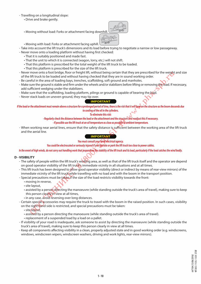
- Travelling on a longitudinal slope:
• Drive and brake gently.
• Moving without load: Forks or attachment facing downhill.
• Moving with load: Forks or attachment facing uphill.
- Take into account the lift truck’s dimensions and its load before trying to negotiate a narrow or low passageway.
- Never move onto a loading platform without having first checked:
• That it is suitably positioned and made fast.
• That the unit to which it is connected (wagon, lorry, etc.) will not shift.
• That this platform is prescribed for the total weight of the lift truck to be loaded.
• That this platform is prescribed for the size of the lift truck.
- Never move onto a foot bridge, floor or freight lift, without being certain that they are prescribed for the weight and size
of the lift truck to be loaded and without having checked that they are in sound working order.
- Be careful in the area of loading bays, trenches, scaffolding, soft ground and manholes.
- Make sure the ground is stable and firm under the wheels and/or stabilizers before lifting or removing the load. If necessary,
add sufficient wedging under the stabilizers.
- Make sure that the scaffolding, loading platform, pilings or ground is capable of bearing the load.
- Never stack loads on uneven ground, they may tip over.
IMPORTANT
If the load or the attachment must remain above a structure for a prolonged period of time, there is the risk that it will bear on the structure as the boom descends due
to cooling of the oil in the cylinders.
To eliminate this risk:
- Regularly check the distance between the load or the attachment and the structure and readjust this if necessary.
- If possible use the lift truck at an oil temperature as close as possible to ambient temperature.
- When working near aerial lines, ensure that the safety distance is sufficient between the working area of the lift truck
and the aerial line.
IMPORTANT
You must consult your local electrical agency.
You could be electrocuted or seriously injured if you operate or park the lift truck too close to power cables.
In the event of high winds, do not carry out handling work that jeopardises the stability of the lift truck and its load, particularly if the load catches the wind badly.
D - VISIBILITY - The safety of people within the lift truck's working area, as well as that of the lift truck itself and the operator are depend
on good operator visibility of the lift truck's immediate vicinity in all situations and at all times.
- This lift truck has been designed to allow good operator visibility (direct or indirect by means of rear-view mirrors) of the
immediate vicinity of the lift truck while travelling with no load and with the boom in the transport position.
- Special precautions must be taken if the size of the load restricts visibility towards the front:
• moving in reverse,
• site layout,
• assisted by a person directing the manoeuvre (while standing outside the truck's area of travel), making sure to keep
this person clearly in view at all times,
• in any case, avoid reversing over long distances.
- Certain special accessories may require the truck to travel with the boom in the raised position. In such cases, visibility
on the right hand side is restricted, and special precautions must be taken:
• site layout,
• assisted by a person directing the manoeuvre (while standing outside the truck's area of travel).
• replacement of a suspended load by a load on a pallet.
- If visibility of your road is inadequate, ask someone to assist by directing the manoeuvre (while standing outside the
truck's area of travel), making sure to keep this person clearly in view at all times.
- Keep all components affecting visibility in a clean, properly adjusted state and in good working order (e.g. windscreens,
windows, windscreen wipers, windscreen washers, driving and work lights, rear-view mirrors).
6471
04 (1
3/06
/201
6)
MT 83
5 / 11
35 / 1
335
ST3B
1 - 11
E - STARTING THE LIFT TRUCKSAFETY INSTRUCTIONS
IMPORTANT
The lift truck must only be started up or manoeuvred when the operator is sitting in the driver’s cab, with his seat belt adjusted and fastened.
- Never try to start the lift truck by pushing or towing it. Such operation may cause severe damage to the transmission.
If necessary, to tow the lift truck in an emergency, the transmission must be placed in the neutral position (see: 3 -
MAINTENANCE: G - OCCASIONAL MAINTENANCE).
- If using an emergency battery for start-up, use a battery with the same characteristics and respect battery polarity when
connecting it. Connect at first the positive terminals before the negative terminals.
IMPORTANT
Failure to respect polarity between batteries can cause serious damage to the electrical circuit.
The electrolyte in the battery may produce an explosive gas. Avoid flames and generation of sparks close to the batteries.
Never disconnect a battery while it is charging.
INSTRUCTIONS
- Check the closing and locking of the hood(s).
- Check that the cab door is closed.
- Check that the forward/reverse selector is in neutral, and that the parking brake is applied.
- Press on the service brake pedal and maintain it down.
- Turn the ignition key to the position I to activate the electrical and pre-heating system.
- Whenever you switch on the lift truck, perform the automatic check on the longitudinal stability limiter and warning device
(see: 2 - DESCRIPTION: INSTRUMENTS AND CONTROLS). Do not use the lift truck if it does not conform to the regulations.
- Check the fuel level on the indicator.
- Turn the ignition key fully, the engine should then start. Release the ignition key and let the engine run at idle.
- Do not engage the starter motor for more than 15 seconds and carry out the preheating between unsuccessful attempts.
- Make sure all the signal lights on the control instrument panel are off.
- Check all control instruments when the engine is warm and at regular intervals during use, so as to quickly detect any
faults and to be able to correct them without any delay.
- If an instrument does not show the correct display, stop the engine and immediately carry out the necessary operations.
F - DRIVING THE LIFT TRUCKSAFETY INSTRUCTIONS
IMPORTANT
The operators' attention is drawn to the risks involved in using the lift truck, in particular:
- Risk of loosing control.
- Risk of loosing lateral and frontal stability of the lift truck.
The operator must remain in control of the lift truck.
In the event of the lift truck overturning, do not try to leave the cabin during the incident.
YOUR BEST PROTECTION IS TO STAY FASTENED IN THE CABIN.
- Observe the company’s traffic regulations or, by default, the public highway code.
- Do not carry out operations which exceed the capacities of your lift truck or attachments.
- Always drive the lift truck with the forks or attachment to the transport position, i.e. at 300 mm from the ground, the
boom retracted and the carriage sloping backwards.
- Only carry loads which are balanced and properly anchored to avoid any risk of a load falling off.
- Ensure that palettes, cases, etc, are in good order and suitable for the load to be lifted.
- Familiarise yourself with the lift truck on the terrain where it will be used.
- Ensure that the service brakes are working properly.
- The loaded lift truck must not travel at speeds in excess of 12 km/h.
- Drive smoothly at an appropriate speed for the operating conditions (land configuration, load on the lift truck).
- Do not use the hydraulic boom controls when the lift truck is moving.
- Never change the steering mode whilst driving.
- Do not manoeuvre the lift truck with the boom in the raised position unless under exceptional circumstances and then
with extreme caution, at very low speed and using gentle braking. Ensure that visibility is adequate.
- Take bends slowly.
- In all circumstances make sure you are in control of your speed.
- On damp, slippery or uneven terrain, drive slowly.
- Brake gently, never abruptly.
- Only use the lift truck’s forward/reverse selector from a stationary position and never do so abruptly.
- Do not drive with your foot on the brake pedal.
- Always remember that hydrostatic type steering is extremely sensitive to movement of the steering wheel, so turn it
gently and not jerkily.
- Never leave the engine on when the lift truck is unattended. 6471
04 (1
3/06
/201
6)
MT 83
5 / 11
35 / 1
335
ST3B
1 - 12
- Do not leave the cab when the lift truck has a raised load.
- Look where you are going and always make sure you have good visibility along the route.
- Use the rear-view mirrors frequently.
- Drive round obstacles.
- Never drive on the edge of a ditch or steep slope.
- It is dangerous to use two lift trucks simultaneously to handle heavy or bulky loads, since this operation requires particular
precautions to be taken. It must only be used exceptionally and after risk analysis.
- The ignition switch has an emergency stop mechanism in case of an operating anomaly occurring in the case of lift trucks
not fitted with a punch-operated cut-out.
INSTRUCTIONS
- Always drive the lift truck with the forks or attachment to the transport position, i.e. at 300 mm from the ground, the
boom retracted and the carriage sloping backwards.
- For lift trucks with gearboxes, use the recommended gear (see: 2 - DESCRIPTION: INSTRUMENTS AND CONTROLS).
- Select the steering mode appropriate for its use and/or working conditions (see: 2 - DESCRIPTION: INSTRUMENTS AND
CONTROLS) (as model of lift truck).
- Release the hand brake.
- Shift the forward/reverse selector to the selected direction of travel and accelerate gradually until the lift truck moves off.
IMPORTANT
Starting and driving a lift truck on a slope can present a very real danger.
The lift truck being parked or stopped, scrupulously follow the following instructions for moving off:
- Press the service brake pedal.
- Engage 1st or 2nd gear and select forward or reverse.
- Check that there is nothing and no-one obstructing the lift truck's path.
- Release the service brake pedal and increase the engine revs.
The risk is increased if the lift truck is laden or towing a trailer, requiring extreme vigilance.
G - STOPPING THE LIFT TRUCKSAFETY INSTRUCTIONS
- Never leave the ignition key in the lift truck during the operator's absence.
- When the lift truck is stationary, or if the operator has to leave his cab (even for a moment), place the forks or attachment
on the ground, apply the parking brake and place the forward/reverse selector in neutral.
- Make sure that the lift truck is not stopped in any position that will interfere with the traffic flow and at less than one
meter from the track of a railway.
- In the event of prolonged parking on a site, protect the lift truck from bad weather, particularly from frost (check the
level of antifreeze), close and lock all the lift truck accesses (doors, windows, cowls, etc.).
INSTRUCTIONS
- Park the lift truck on flat ground or on an incline lower than 15 %.
- Set the forward/reverse selector to neutral.
- Engage the parking brake.
- For lift trucks with gearboxes, place the gear lever in neutral.
- Fully retract the boom.
- Lower the forks or attachment to rest on the ground.
- When using an attachment with a grab or jaws, or a bucket with hydraulic opening, close the attachment fully.
- Before stopping the lift truck after a long working period, leave the engine idling for a few moments, to allow the coolant
liquid and oil to lower the temperature of the engine and transmission. Do not forget this precaution, in the event of
frequent stops or warm stalling of the engine, or else the temperature of certain parts will rise significantly due to the
stopping of the cooling system, with the risk of badly damaging such parts.
- Stop the engine with the ignition switch.
- Remove the ignition key.
- Lock all the accesses to the lift truck (doors, windows, cowls…).
6471
04 (1
3/06
/201
6)
MT 83
5 / 11
35 / 1
335
ST3B
1 - 13
H - DRIVING THE LIFT TRUCK ON THE PUBLIC HIGHWAY(or see current legislation in other countries)
FRENCH ROAD TRAFFIC RULES
- The driving of non EC type-approved tractors on the public highway is subject to the provisions of the highway code relating to special machines, defined in article R311-1
of the highway code, in category B of the Equipment Order of 20 November 1969 that determines the procedures applicable to special machines. The lift truck must be
fitted with a licence plate.
- The driving of EC type-approved tractors on the public highway is subject to the provisions of the highway code regarding agricultural tractors, defined in article R311-1 of
the highway code. The lift truck must be registered.
- The lift truck must be driven on the public highway in accordance with the instructions given in the manual supplied with the lift truck (Gross weight, Gross combination
weight, towing load, axle loads, maximum speeds, etc. according to type/version). The operator must be in possession of the lift truck’s registration document.
- The operator must hold an HGV licence, unless granted an exemption.
- When towing a trailer or agricultural equipment, the travelling speed of the lift truck is limited to 25 km/h. In this case, a "25" disc must be affixed to the rear of the convoy.
When driving with a trailer, the fact of not engaging 4th gear will ensure compliance with the towing speed limit (max. 25 km/h). On "POWERSHIFT" models, as 3rd gear is
slower than on other models, it is preferable to use 5th gear and disable automatic upshifting to 6th gear (see: 2 - DESCRIPTION: INSTRUMENTS AND CONTROLS).
SAFETY INSTRUCTIONS
- Operators driving on the public highway must comply with current highway code legislation.
- The lift truck must comply with current road legislation. If necessary, there are optional solutions. Contact your dealer.
INSTRUCTIONS
- Make sure the revolving light is in place, switch it on and verify its operation.
- Make sure the lights, indicators and windscreen wipers are working properly.
- Switch off the working headlights if the lift truck is fitted with them.
- Select the steering mode "HIGHWAY TRAFFIC" (as model of lift truck) (see: 2 - DESCRIPTION: INSTRUMENTS AND CONTROLS).
- Fully retract the boom and set the attachment approximately 300 mm off the ground.
- Place the roll corrector in the central position, i.e. the transverse axis of the axles parallel to the chassis (as model of lift
truck).
- Fully raise the stabilizers and turn the blocks inwards (according to model of lift truck).
IMPORTANT
Never coast in neutral (forward/reverse selector or gear lever in neutral or transmission cut-off button pressed) to preserve the lift truck engine brake.
Failure to observe this instruction on a slope will lead to excessive speed which may make the lift truck uncontrollable (steering, brakes) and cause serious
mechanical damage.
DRIVING THE LIFT TRUCK WITH A FRONT-MOUNTED ATTACHMENT
- You must comply with current regulations in your country, covering the possibility of driving on the public highway with
a front-mounted attachment on your lift truck.
- If road legislation in your country authorizes circulation with a front-mounted attachment, you must at least:
• Protect and report any sharp and/or dangerous edges on the attachment (see: 4 - ADAPTABLE ATTACHMENTS IN
OPTION ON THE RANGE: ATTACHMENT SHIELDS).
• The attachment must not be loaded.
• Make sure that the attachment does not mask the lighting range of the forward lights.
• Make sure that current legislation in your country does not require other obligations.
OPERATING THE LIFT TRUCK WITH A TRAILER
- For using a trailer, observe the regulations in force in your country (maximum travel speed, braking, maximum weight
of trailer, etc.).
- Do not forget to connect the trailer’s electrical equipment to that of the lift truck.
- The trailer's braking system must comply with current legislation.
- If pulling a trailer with assisted braking, the tractor lift truck must be equipped with a trailer braking mechanism. In this
case, do not forget to connect the trailer braking equipment to the lift truck.
- The vertical force on the towing hook must not exceed the maximum authorised by the manufacturer (consult the
manufacturer’s plate on your lift truck).
- The authorised gross vehicle weight must not exceed the maximum weight authorised by the manufacturer (see: 2 -
DESCRIPTION: CHARACTERISTICS).
IF NECESSARY, CONSULT YOUR DEALER.
6471
04 (1
3/06
/201
6)
MT 83
5 / 11
35 / 1
335
ST3B

1 - 14
INSTRUCTIONS FOR HANDLING A LOAD
A - CHOICE OF ATTACHMENTS - Only attachments approved by MANITOU can be used on its lift trucks.
- Make sure the attachment is appropriate for the work to be done (see: 4 - ADAPTABLE ATTACHMENTS IN OPTION ON
THE RANGE).
- If the lift truck is equipped with the Single side-shift carriage OPTION (TSDL), use only the authorised attachments (see:
4 - ADAPTABLE ATTACHMENTS IN OPTION ON THE RANGE).
- Make sure the attachment is correctly installed and locked onto the lift truck carriage.
- Make sure that your lift truck attachments work properly.
- Comply with the load chart limits for the lift truck for the attachment used.
- Do not exceed the rated capacity of the attachment.
- Never lift a load in a sling without the attachment provided for the purpose, as the sling risks to slip (see: INSTRUCTIONS
FOR HANDLING A LOAD: H - TAKING UP AND LAYING DOWN A SUSPENDED LOAD).
- Do not handle loads that are hung directly from the forks with straps (e.g.: big-bag), as there is a risk that the straps will
shear against the sharp edges. Use an attachment designed for this purpose.
B - MASS OF LOAD AND CENTRE OF GRAVITY - Before taking up a load, you must know its mass and its centre of gravity.
- The load chart for your lift truck is valid for a load in which the longitudinal position
of the centre of gravity is 500 mm from the base of the forks (fig. B1). For a higher
centre of gravity, contact your dealer.
- For irregular loads, determine the transverse centre of gravity before any movement
(fig. B2) and set it in the longitudinal axis of the lift truck.
IMPORTANT
It is forbidden to move a load heavier than the effective capacity defined on the lift truck load chart.
For loads with a moving centre of gravity (e.g. liquids), take account of the variations in the centre of gravity in order
to determine the load to be handled and be vigilant and take extra care to limit these variations as far as possible.
C - LONGITUDINAL STABILITY LIMITER AND WARNING DEVICEThis device gives an indication of the longitudinal stability of the lift truck, and limits
hydraulic movements in order to ensure this stability, at least under the following
operating conditions:
• when the lift truck is at a standstill,
• when the lift truck is on firm, stable and consolidated ground,
• when the lift truck is performing handling and placing operations.
- Move the jib very carefully when approaching the authorized load limit (see: 2 -
DESCRIPTION: INSTRUMENTS AND CONTROLS).
- Always watch this device during handling operations.
- In the event that "AGGRAVATING" hydraulic movements are cut-off, only perform
de-aggravating hydraulic movements in the following order (fig. C): if necessary,
raise the jib (1), retract the jib as far as possible (2) and lower the jib (3) to set down
the load.
IMPORTANT
The instrument reading may be erroneous when the steering is at full lock or the rear axle is oscillated to its maximum extent.
Before lifting a load, make sure that the lift truck is not in either of these situations.
12
3
C
500 mm
B1
B2
6471
04 (1
3/06
/201
6)
MT 83
5 / 11
35 / 1
335
ST3B

1 - 15
D - TRANSVERSE ATTITUDE OF THE LIFT TRUCKDepending on the model of lift truck
The transverse attitude is the transverse slope of the chassis with respect to the horizontal.
Raising the jib reduces the lift truck's lateral stability. The transverse attitude must be set with the jib in down position as follows:
1 - LIFT TRUCK WITHOUT ROLL CORRECTOR USED ON TYRES
- Position the lift truck so that the bubble in the level is between the two lines (see: 2 - DESCRIPTION: INSTRUMENTS AND
CONTROLS).
2 - LIFT TRUCK WITH ROLL CORRECTOR USED ON TYRES
- Correct the roll using the hydraulic control and check horizontality with the spirit level. The bubble in the level must
be between the two lines (see: 2 - DESCRIPTION: INSTRUMENTS AND CONTROLS).
3 - LIFT TRUCK USED ON STABILIZERS
- Set the two stabilizers on the ground and raise the two front wheels of the lift
truck (fig. D1).
- Correct the roll using the stabilizers (fig. D2) and check horizontality with the spirit
level. The bubble of the level must be between the two lines (see: 2 - DESCRIPTION:
INSTRUMENTS AND CONTROLS). In this position, the two front wheels must be off
the ground.
E - TAKING UP A LOAD ON THE GROUND - Approach the lift truck perpendicular to the load, with the jib retracted and the
forks in a horizontal position (fig. E1).
- Adjust the fork spread and centring relative to the load to ensure stability (fig. E2)
(optional solutions exist, consult your dealer).
- Never lift a load with a single fork.
IMPORTANT
Beware of the risks of trapping or squashing limbs when manually adjusting the forks.
- Move the lift truck forward slowly (1) and insert the forks under the load as far as
they will go (fig. E3). If necessary, slightly lift the jib (2) while taking up the load.
- Bring the load into the transport position.
- Tilt the load far enough backwards to ensure stability (loss of load on braking or
going downhill).
FOR A NON-PALLETISED LOAD
- Tilt the carriage (1) forwards and move the lift truck slowly forwards (2), to insert
the fork under the load (fig. E4) (block the load if necessary).
- Continue to move the lift truck forwards (2) tilting the carriage (3) (fig. E4) backwards
to position the load on the forks and check the load's longitudinal and lateral stability.
E1
E2
12
E3
1
2
3
E4
D2
D1
6471
04 (1
3/06
/201
6)
MT 83
5 / 11
35 / 1
335
ST3B

1 - 16
F - TAKING UP AND LAYING A HIGH LOAD ON TYRES IMPORTANT
You must not raise the jib if you have not checked the transverse attitude of the lift truck (see: INSTRUCTIONS FOR
HANDLING A LOAD: D - TRANSVERSE ATTITUDE OF THE LIFT TRUCK).
REMINDER: Make sure that the following operations can be performed with good
visibility (see: OPERATIONS INSTRUCTIONS UNLADEN AND LADEN: D
- VISIBILITY).
TAKING UP A HIGH LOAD ON TYRES
- Ensure that the forks will easily pass under the load.
- Lift and extend the jib (1) (2) until the forks are level with the load, moving the lift
truck (3) forward if necessary (fig. F1), moving very slowly and carefully.
- Always remember to keep the distance necessary for inserting the forks under the
load, between the stack and the lift truck (fig. F1) and use the shortest possible
length of jib.
- Insert the forks under the load as far as they will go by alternately extending and
lowering the jib (1) or, if necessary, moving the lift truck forward (2) (fig. F2). Apply
the handbrake and place the forward/reverse selector in neutral.
- Slightly raise the load (1) and tilt the carriage (2) backwards to stabilize the load
(fig. F3).
- Tilt the load sufficiently backwards to ensure its stability.
- Monitor the longitudinal stability limiter and warning device (see: INSTRUCTIONS FOR
HANDLING A LOAD: C - LONGITUDINAL STABILITY LIMITER AND WARNING DEVICE).
If it is overloaded, set the load back down in the place from which it was taken.
- If possible lower the load without shifting the lift truck. Lift the jib (1) to release the
load, retract (2) and lower the jib (3) to bring the load into the transport position
(fig. F4).
- If this is not possible, back up the lift truck (1), manoeuvring very gently and
carefully to release the load. Retract (2) and lower the jib (3) to bring the load into
the transport position (fig. F5).
1
2
3
F1
1
2
F2
1
2
F3
1
3
2
F4
1
2
3
F5
6471
04 (1
3/06
/201
6)
MT 83
5 / 11
35 / 1
335
ST3B

1 - 17
LAYING A HIGH LOAD ON TYRES
- Approach the load in the transport position in front of the stack (fig. F6).
- Apply the parking brake and place the forward/reverse selector in neutral.
- Raise and extend the jib (1) (2) until the load is above the stack, while monitoring
the longitudinal stability limiter and warning device (see: INSTRUCTIONS FOR
HANDLING A LOAD: C - LONGITUDINAL STABILITY LIMITER AND WARNING DEVICE).
If necessary, move the lift truck (3) forward (fig. F7), driving very slowly and carefully.
- Place the load in a horizontal position and lay it down on the pile by lowering and
retracting the jib (1) (2) in order to position the load correctly (fig. F8).
- If possible, release the fork by alternately retracting and raising the jib (1) (fig. F9).
Then set the forks into transport position.
- If this is not possible, reverse the lift truck (1) very slowly and carefully to release
the forks (fig. F10). Then set them into transport position.
F6
1
2
3
F7
1
2
F8
1
F9
1
F10
6471
04 (1
3/06
/201
6)
MT 83
5 / 11
35 / 1
335
ST3B
1 - 18
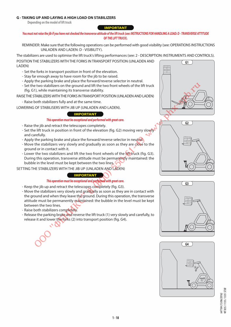
G - TAKING UP AND LAYING A HIGH LOAD ON STABILIZERSDepending on the model of lift truck
IMPORTANT
You must not raise the jib if you have not checked the transverse attitude of the lift truck (see: INSTRUCTIONS FOR HANDLING A LOAD: D - TRANSVERSE ATTITUDE
OF THE LIFT TRUCK).
REMINDER: Make sure that the following operations can be performed with good visibility (see: OPERATIONS INSTRUCTIONS
UNLADEN AND LADEN: D - VISIBILITY).
The stabilizers are used to optimise the lift truck's lifting performances (see: 2 - DESCRIPTION: INSTRUMENTS AND CONTROLS).
POSITION THE STABILIZERS WITH THE FORKS IN TRANSPORT POSITION (UNLADEN AND
LADEN)
- Set the forks in transport position in front of the elevation.
- Stay far enough away to have room for the jib to be raised.
- Apply the parking brake and place the forward/reverse selector in neutral.
- Set the two stabilizers on the ground and lift the two front wheels of the lift truck
(fig. G1), while maintaining its transverse stability.
RAISE THE STABILIZERS WITH THE FORKS IN TRANSPORT POSITION (UNLADEN AND LADEN)
- Raise both stabilizers fully and at the same time.
LOWERING OF STABILISERS WITH JIB UP (UNLADEN AND LADEN).
IMPORTANT
This operation must be exceptional and performed with great care.
- Raise the jib and retract the telescopes completely.
- Set the lift truck in position in front of the elevation (fig. G2) moving very slowly
and carefully.
- Apply the parking brake and place the forward/reverse selector in neutral.
- Move the stabilizers very slowly and gradually as soon as they are close to the
ground or in contact with it.
- Lower the two stabilizers and lift the two front wheels of the lift truck (fig. G3).
During this operation, transverse attitude must be permanently maintained: the
bubble in the level must be kept between the two lines.
SETTING THE STABILIZERS WITH THE JIB UP (UNLADEN AND LADEN)
IMPORTANT
This operation must be exceptional and performed with great care.
- Keep the jib up and retract the telescopes completely (fig. G3).
- Move the stabilizers very slowly and gradually as soon as they are in contact with
the ground and when they leave the ground. During this operation, the transverse
attitude must be permanently maintained: the bubble in the level must be kept
between the two lines.
- Raise both stabilizers completely.
- Release the parking brake and reverse the lift truck (1) very slowly and carefully, to
release it and lower the forks (2) into transport position (fig. G4).
G1
G2
G3
1
2
G4
6471
04 (1
3/06
/201
6)
MT 83
5 / 11
35 / 1
335
ST3B

1 - 19
TAKING UP A HIGH LOAD ON STABILISERS
- Ensure that the forks will easily pass under the load.
- Check the position of the lift truck with respect to the load and make a test run,
if necessary, without taking the load.
- Raise and extend the jib (1) (2) until the forks are at the level of the load (fig. G5).
- Insert the forks under the load as far as they will go by alternately extending and
lowering the jib (1) (fig. G6).
- Lift the load slightly (1) and tilt the carriage (2) backwards to stabilise the load (fig. G7).
- Monitor the longitudinal stability limiter and warning device (see: INSTRUCTIONS FOR
HANDLING A LOAD: C - LONGITUDINAL STABILITY LIMITER AND WARNING DEVICE).
If it is overloaded, set the load back down in the place from which it was taken.
- If possible lower the load without moving the lift truck. Raise the jib (1) to release the
load, retract (2) and lower the jib (3) to set the load into transport position (fig. G8).
LAYING A HIGH LOAD ON STABILISERS
- Raise and extend the jib (1) (2) until the load is above the elevation (fig. G9), while
monitoring the longitudinal stability limiter and warning device (see: INSTRUCTIONS
FOR HANDLING A LOAD: C - LONGITUDINAL STABILITY LIMITER AND WARNING
DEVICE).
- Position the load horizontally and release it by lowering and retracting the jib (1)
(2) to position the load correctly (fig. G10).
- Free the forks by alternating retracting and raising the jib (3) (fig. G11).
- If possible, set the jib in transport position without moving the lift truck.
1
2
G5
1
G6
1
2
3
G8
1
2
G7
1
2
G9
3
G11
1
2
G10
6471
04 (1
3/06
/201
6)
MT 83
5 / 11
35 / 1
335
ST3B

1 - 20
H - TAKING UP AND LAYING DOWN A SUSPENDED LOAD IMPORTANT
Failure to follow the above instructions may lead the lift truck to loose stability and overturn.
MUST be used with a lift truck equipped with an operational hydraulic movement cut-out device.
CONDITIONS OF USE
- The length of the sling or the chain shall be as short as possible to limit swinging of the load.
- Lift the load vertically along its axis, never by pulling sideways or lengthways.
HANDLING WITHOUT MOVING THE LIFT TRUCK
- Whether on stabilisers or on tyres, the lateral attitude must not exceed 1 % and the longitudinal attitude must not exceed
5%, the bubble of the level must be held at "0".
- Ensure that the wind speed is not higher than 10 m/s.
- Ensure that there is no one between the load and the lift truck.
I - TRAVELLING WITH A SUSPENDED LOAD - Before moving, inspect the terrain in order to avoid excessive slopes and cross-falls, bumps and potholes, or soft ground.
- Ensure that the wind speed is not higher than 36 km/h.
- The lift truck must not travel at more than 0,4 m/s (1,5 km/h, i.e., one quarter walking speed).
- Drive and stop the lift truck gently and smoothly to minimise swinging of the load.
- Carry the load a few centimetres above the ground (max. 30 cm) the shortest possible jib length. Do not exceed the
offset indicated on the load chart. If the load begins to swing excessively, do not hesitate to stop and lower the jib to
set down the load.
- Before moving the lift truck, check the longitudinal stability limiter and warning device (see: 2 - DESCRIPTION: INSTRUMENTS
AND CONTROLS), only the green LEDs and possible the yellow LEDs should be lit.
- During transport, the lift truck operator must be assisted by a person on the ground (standing a minimum of 3 m from
the load), who will limit swinging of the load using a bar or a rope. Ensure that this person is always clearly in view.
- The lateral attitude must not exceed 5 %, the bubble in the level must be kept between the two "MAX" marks
- The longitudinal attitude must not exceed 15 %, with the load facing uphill, and 10%, with the load facing downhill.
- The jib angle must not exceed 45°.
- If the first red LED of longitudinal stability limiter and warning device (see: 2 - DESCRIPTION: INSTRUMENTS AND CONTROLS)
comes on while travelling, gently bring the lift truck to a halt and stabilise the load. Retract the telescope to reduce the
offset of the load.
6471
04 (1
3/06
/201
6)
MT 83
5 / 11
35 / 1
335
ST3B

1 - 21
PLATFORM OPERATING INSTRUCTIONS
For lift trucks fitted with a PLATFORM
A - AUTHORISATION FOR USE - Operation of the platform requires further authorisation in addition to that of the lift truck.
B - LIFT TRUCK SUITABILITY FOR USE - MANITOU has ensured that this platform is suitable for use under the normal operating conditions defined in this operator's
manual, with a STATIC test coefficient OF 1,25 and a DYNAMIC test coefficient OF 1,1, as specified in harmonised standard
EN 280 for "mobile elevating work platforms".
- Before commissioning, the company manager must make sure that platform is appropriate for the work to be done, and
perform certain tests (in accordance with current legislation).
C - PRECAUTIONS WHEN USING THE PLATFORM - Wear suitable clothing when using the platform, avoid loosely-fitting garments.
- Never operate the platform when hands or feet are wet or soiled with greasy substances.
- Remain alert at all times when using the platform. Do not listen to the radio or music using headphones or earphones.
- For increased comfort, adopt the correct position at the platform's operator station.
- The platform's guard rail exempts the operator from wearing a safety harness under normal operating conditions. As a
result, you are responsible for deciding whether to wear a safety harness.
- The control units must never in any event be used for any other than their intended purposes (e.g. climbing onto or down
from the lift truck, portmanteau, etc.).
- Safety helmets must be worn.
- The operator must always be in the normal operator's position. It is prohibited to have arms or legs, or generally any part
of the body, protruding from the basket.
- Ensure that any materials loaded onto the platform (pipes, cables, containers, etc.) cannot fall out. Do not pile these
materials to the point where it is necessary to step over them.
D - USING THE PLATFORM - However experienced they may be, operators must acquaint themselves with the emplacement and operation of all
control instruments prior to operating the platform.
- Check before use that the platform has been correctly assembled and locked onto the lift truck.
- Check before operating the platform that the access gate has been properly locked.
- The platform should be operated in an area free of any obstructions or danger when it is lowered to the ground.
- The operator using the platform must be aided on the ground by a person with adequate training.
- You should stay within the limits set out in the platform load chart.
- The lateral stresses are limited pressure (see: 2 - DESCRIPTION: CHARACTERISTICS).
- It is strictly forbidden to hang a load from the platform or the lift truck jib without a specially designed attachment
(see: INSTRUCTIONS FOR HANDLING A LOAD: H - TAKING UP AND LAYING DOWN A SUSPENDED LOAD).
- The platform cannot be used as a crane or a lift for permanently transporting people or materials, nor as jacks or supports.
- The lift truck must not be moved with one (or more) person(s) in the platform.
- It is forbidden to transport people on the platform using the hydraulic controls in the lift truck’s driver’s cab (except in
case of rescue).
- The operator must not climb onto to off the platform when it is not on ground level (jib retracted and in the down position).
- The platform must not be fitted with attachments that increase the unit's wind load.
- Do not use ladders or improvised structures in the platform to gain extra height.
- Do not climb onto the sides of the platform to gain extra height.
- It is forbidden to use the platform on forks. The fork slots are only to, be used for storing the platform and not for lifting
people under any circumstances.
E - ENVIRONMENT IMPORTANT
It is forbidden to use the platform close to electricity cables. Maintain the specified safe distances.
RATED VOLTAGE DISTANCE ABOVE GROUND OR FLOOR IN METRES50 < U < 1000 2,30 M
1000 < U < 30000 2,50 M30000 < U < 45000 2,60 M45000 < U < 63000 2,80 M63000 < U < 90000 3,00 M
90000 < U < 150000 3,40 M150000 < U < 225000 4,00 M225000 < U < 400000 5,30 M400000 < U < 750000 7,90 M
6471
04 (1
3/06
/201
6)
MT 83
5 / 11
35 / 1
335
ST3B
1 - 22
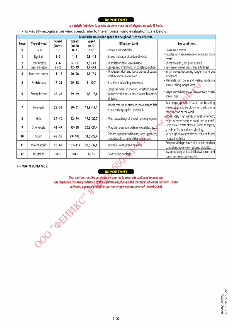
IMPORTANT
It is strictly forbidden to use the platform when the wind speed exceeds 45 km/h.
- To visually recognise this wind speed, refer to the empirical wind evaluation scale below:
BEAUFORT scale (wind speed at a height of 10 m on a flat site)
Force Type of wind Speed (knots)
Speed (km/h)
Speed (m/s) Effects on Land Sea conditions
0 Calm 0 - 1 0 - 1 < 0,3 - Smoke rises vertically. - Sea is like a mirror.
1 Light air 1 - 3 1 - 5 0,3 - 1,5 - Smoke indicates direction of wind. - Ripples with appearance of scale, no foam
crests.2 Light breeze 4 - 6 6 - 11 1,6 - 3,3 - Wind felt on face, leaves rustle. - Short wavelets, but pronounced.3 Gentle breeze 7 - 10 12 - 19 3,4 - 5,4 - Leaves and small twigs in constant motion. - Very small waves, crests begin to break.
4 Moderate breeze 11 - 16 20 - 28 5,5 - 7,9 - Wind raises dust and loose pieces of paper;
small branches are moved.
- Small waves, becoming longer, numerous
whitecaps.
5 Fresh breeze 17 - 21 29 - 38 8 - 10,7 - Small tees in leaf begin to sway. - Wavelets form on inland waters; moderate
waves, taking longer form.
6 Strong breeze 22 - 27 39 - 49 10,8 - 13,8 - Large branches in motion, whistling heard
in overhead wires, umbrella use becomes
difficult.
- Larger waves forming, whitecaps everywhere,
some spray.
7 Near gale 28 - 33 50 - 61 13,9 - 17,1 - Whole trees in motion, inconvenience felt
when walking against the wind.
- Sea heaps up; white foam from breaking
waves begins to be blown in streaks along
the direction of the wind.
8 Gale 34 - 40 62 - 74 17,2 - 20,7 - Wind breaks twigs off trees; impedes progress. - Moderately high waves of greater length;
edges of crests begin to break into spindrift.
9 Strong gale 41 - 47 75 - 88 20,8 - 24,4 - Wind damages roofs (chimneys, slates, etc.). - High waves, crests of waves begin to topple,
streaks of foam; reduced visibility.
10 Storm 48 - 55 89 - 102 24,5 - 28,4 - Seldom experienced inland; trees uprooted;
considerable structural damage occurs.
- Very high waves; white streaks of foam;
reduced visibility.
11 Violent storm 56 - 63 103 - 117 28,5 - 32,6 - Very rare, widespread damage. - Exceptionally high waves able to hide medium
sized ships from view, reduced visibility.
12 Hurricane 64 + 118 + 32,7 + - Devastating damage. - Sea completely white; air filled with foam and
spray, very reduced visibility.
F - MAINTENANCE IMPORTANT
Your platform must be periodically inspected to ensure its continued compliance.
The inspection frequency is defined by the legislation applying in the country in which the platform is used.
In France, a general periodic inspection every 6 months (order of 1 March 2004).
6471
04 (1
3/06
/201
6)
MT 83
5 / 11
35 / 1
335
ST3B
1 - 23
INSTRUCTIONS FOR USING THE RADIO-CONTROL
For lift trucks with RC radio control
HOW TO USE THE RADIO-CONTROLSAFETY INSTRUCTIONS
- This radio-control consists of electronic and mechanical safety elements. It cannot receive commands from another
transmitter because the internal encoding is unique to each radio-control.
IMPORTANT
If it is used improperly or incorrectly, there is a risk of danger to:
- The physical and mental health of the user or others.
- The lift truck and other neighbouring items.
All those working with this radio-control:
- Must be qualified in line with current regulations and trained accordingly.
- Must follow this instruction manual as closely as possible.
- The system is used to control the lift truck remotely via radio waves. Commands are also transmitted if the lift truck is
out of sight (behind an obstacle or a building for example), this is why:
• After stopping the truck and removing the key switch (only possible when it is stationary), always place the transmitter
in a safe, dry place.
• Before performing any installation, servicing or repair work, always switch off power sources (in particular, electric
welding devices and electric head units on hydraulic distributors must be disconnected at each section).
• Never remove or alter the safety devices (such as the hand-guard frame, key, emergency stop button, etc.).
IMPORTANT
Never drive the lift truck if it is not continuously and perfectly within view of the operator!
- Before leaving the transmitter, the operator must make sure that it cannot be used by an unauthorized third person:
either by removing the key button from the transmitter or locking it in an inaccessible place.
- The user must ensure that the instruction manual is accessible at all times and that operators have read and understood it.
INSTRUCTIONS
- Take up position in a stable place with no risk of slipping.
- Before using the transmitter, make sure there is nobody within the working area.
- Only use the transmitter with its carrying device or installed correctly on the platform.
IMPORTANT
When you remove the transmitter, remove the accumulator and key button so that it cannot be used accidentally or deliberately by anyone else.
PROTECTIVE DEVICES - The lift truck will be immobilised within a maximum of 450 milliseconds (approx. 0.5 second):
• If the emergency stop button of the transmitter is pressed (50 milliseconds), or that of the lift truck.
• If the transmission distance of the radio waves is exceeded.
• If the transmitter is faulty.
• If an interfering radio signal is received from elsewhere.
• If the accumulator is removed from its housing in the transmitter.
• If the battery reaches the end of its autonomy.
• If the transmitter is switched off by turning the key switch to the off position.
- These protective devices are provided for the safety of personnel and property and must never be altered, removed
or bypassed in any way whatsoever!
- The hand-guard frame prevents external action on a manipulator (e.g. if the transmitter is dropped, or if the operator
leans on a guard-rail).
- An electronic safety device prevents radio transmission from being initiated if the manipulators are not mechanically
and electrically at rest and if the internal combustion engine speed selector is not set to idle.
IMPORTANT
In an emergency, press the transmitter emergency stop button immediately ; then follow the manual's instructions (see: 2 - DESCRIPTION: INSTRUMENTS AND CONTROLS).
6471
04 (1
3/06
/201
6)
MT 83
5 / 11
35 / 1
335
ST3B

1 - 24
LIFT TRUCK MAINTENANCE INSTRUCTIONS
GENERAL INSTRUCTIONS
- Ensure the area is sufficiently ventilated before starting the lift truck.
- Wear clothes suitable for the maintenance of the lift truck, avoid wearing jewellery and loose clothes. Tie and protect
your hair, if necessary.
- Stop the engine and remove the ignition key, when an intervention is necessary.
- Read the operator's manual carefully.
- Carry out all repairs immediately, even if the repairs concerned are minor.
- Repair all leaks immediately, even if the leak concerned is minor.
- Make sure that the disposal of process materials and of spare parts is carried out in total safety and in a ecological way.
- Be careful of the risk of burning and splashing (exhaust, radiator, engine, etc.).
PLACING THE JIB SAFETY WEDGE
- The lift truck is equipped with a jib safety wedge (see: 2 - DESCRIPTION: INSTRUMENTS
AND CONTROLS) that must be installed on the rod of the lifting cylinder when
working beneath the jib.
FITTING THE WEDGE - Fully raise the jib.
- Place the safety wedge 1 on the rod of the lifting cylinder and secure with the rod
2 and the pin 3.
- Slowly lower the jib then stop the hydraulic movements before it comes into
contact with the wedge.
REMOVING THE WEDGE - Fully raise the jib.
- Remove the pin and the rod.
- Return the safety wedge to the storage location provided on the lift truck.
IMPORTANT
Only use the wedge supplied with the lift truck.
MAINTENANCE
- Perform the periodic service (see: 3 - MAINTENANCE) to keep your lift truck in good working conditions. Failure to perform
the periodic service may cancel the contractual guarantee.
MAINTENANCE LOGBOOK - The maintenance operations carried out in accordance with the recommendations given in part: 3 - MAINTENANCE and
the other inspection, servicing or repair operations or modifications performed on the lift truck or its attachments shall
be recorded in a maintenance logbook. The entry for each operation shall include details of the date of the works, the
names of the individuals or companies having performed them, the type of operation and its frequency, if applicable.
The part numbers of any lift truck items replaced shall also be indicated.
2
3
1
6471
04 (1
3/06
/201
6)
MT 83
5 / 11
35 / 1
335
ST3B
1 - 25
LUBRICANT AND FUEL LEVELS
- Use the recommended lubricants (never use contaminated lubricants).
- Do not fill the fuel tank when the engine is running.
- Only fill up the fuel tank in areas specified for this purpose.
- Do not fill the fuel tank to the maximum level.
- Do not smoke or approach the lift truck with a flame, when the fuel tank is open or is being filled.
HYDRAULIC
- Any work on the load handling hydraulic circuit is forbidden except for the operations described in part: 3 - MAINTENANCE.
- Do not attempt to loosen unions, hoses or any hydraulic component with the circuit under pressure.
IMPORTANT
BALANCING VALVE: It is dangerous to change the setting and remove the balancing valves or safety valves which may be fitted to your lift truck cylinders.
The HYDRAULIC ACCUMULATORS that may be fitted on your lift truck are pressurised units. Removing these accumulators and their pipework is a dangerous operation
and must only be performed by approved personnel (consult your dealer).
ELECTRICITY
- Do not short-circuit the starter relay to start the engine. If the forward/reverse selector is not in neutral and the parking
brake is not applied, the lift truck may suddenly start to move.
- Do not drop metallic items on the battery.
- Disconnect the battery before working on the electrical circuit.
WELDING
- Disconnect the battery before any welding operations on the lift truck.
- When carrying out electric welding work on the lift truck, connect the negative cable from the equipment directly to the
part being welded, so as to avoid high tension current passing through the alternator.
- Never carry out welding or work which gives off heat on an assembled tyre. The heat would increase the pressure which
could cause the tyre to explode.
- If the lift truck is equipped with an electronic control unit, disconnect this before starting to weld, to avoid the risk of
causing irreparable damage to electronic components.
WASHING THE LIFT TRUCK
- Clean the lift truck or at least the area concerned before any intervention.
- Remember to close and lock all accesses to the lift truck (doors, windows, cowls…).
- During washing, avoid the articulations and electrical components and connections.
- If necessary, protect against penetration of water, steam or cleaning agents, components susceptible of being damaged,
particularly electrical components and connections and the injection pump.
- Clean the lift truck of any fuel, oil or grease trace.
TRANSPORTING THE LIFT TRUCK
IMPORTANT
Transporting the lift truck involves real risks for the operator and others involved.
- Towing, slinging or transporting the lift truck (see: 3 - MAINTENANCE: G - OCCASIONAL MAINTENANCE).
6471
04 (1
3/06
/201
6)
MT 83
5 / 11
35 / 1
335
ST3B

1 - 26
IF THE LIFT TRUCK IS NOT TO BE USED FOR A LONG TIME
INTRODUCTION
The following recommendations are intended to prevent the lift truck from being damaged when it is withdrawn from service
for an extended period.
IMPORTANT
Procedures to follow if the lift truck is not to be used for a long time and for starting it up again afterwards must be performed by your dealership. This long-term storage
period must not exceed 12 months.
PREPARING THE LIFT TRUCK
- Clean the lift truck thoroughly.
- Check and repair any fuel, oil, water or air leaks.
- Replace or repair any worn or damaged parts.
- Wash the painted surfaces of the lift truck in clear and cold water and wipe them.
- Touch up the paintwork if necessary.
- Shut down the lift truck (see: OPERATING INSTRUCTIONS UNLADEN AND LADEN).
- Make sure the jib cylinder rods are all in retracted position.
- Release the pressure in the hydraulic circuits.
PROTECTING THE ENGINE
- Fill the tank with fuel (see: 3 - MAINTENANCE: A - DAILY OR EVERY 10 HOURS SERVICE).
- Empty and replace the cooling liquid (see: 3 - MAINTENANCE: F - EVERY 2000 HOURS SERVICE).
- Leave the engine running at idling speed for a few minutes, then switch off.
- Replace the engine oil and oil filter (see: 3 - MAINTENANCE: D - EVERY 500 HOURS SERVICE).
- Run the engine for a short time so that the oil and cooling liquid circulate inside.
- Disconnect the battery and store it in a safe place away from the cold, after charging it to a maximum.
- Block the outlet with waterproof adhesive tape.
- Remove the drive belts and store them in a safe place.
- Disconnect the engine cut-off solenoid on the injection pump and carefully insulate the connection.
PROTECTING THE LIFT TRUCK
- Set the lift truck on axle stands so that the tires are not in contact with the ground and release the parking brake.
- Protect cylinder rods which will not be retracted, from corrosion.
- Wrap the tires.
NOTE: If the lift truck is to be stored outdoors, cover it with a waterproof tarpaulin.
BRINGING THE LIFT TRUCK BACK INTO SERVICE
- Remove the waterproof adhesive tape from all the holes.
- Refit and reconnect the battery.
- Remove the protection from the cylinder rods.
- Perform the daily service (see: 3 - MAINTENANCE: A - DAILY OR EVERY 10 HOURS SERVICE).
- Put the handbrake on and remove the axle stands.
- Empty and replace the fuel and replace the fuel filter (see: 3 - MAINTENANCE: D - EVERY 500 HOURS SERVICE).
- Refit and set the tension in the drive belts (see: 3 - MAINTENANCE: FILTERS CARTRIDGES AND BELTS).
- Turn the engine over with the starter, to allow the oil pressure to rise.
- Reconnect the engine cut-off solenoid.
- Lubricate the lift truck completely (see: 3 - MAINTENANCE: SERVICING SCHEDULE).
IMPORTANT
Ensure the area is sufficiently ventilated before starting the lift truck.
- Start up the lift truck, following the safety instructions and regulations (see: OPERATING INSTRUCTIONS UNLADEN AND LADEN).
- Run all the jib's hydraulic movements, concentrating on the ends of travel for each cylinder.
6471
04 (1
3/06
/201
6)
MT 83
5 / 11
35 / 1
335
ST3B

1 - 27
LIFT TRUCK DISPOSAL
MANITOU complies with the regulations deriving from Directive 2000/53/EC relating to lift truck end-of-life.
This lift truck contains no substances or materials forbidden by Directive 2000/53/EC.
NOTE: Consult your dealer before disposing of your lift truck.
RECYCLING OF MATERIALS
METALS• Metals are 100 % recoverable and recyclable.
PLASTICS• Plastic parts are identified with a marking in accordance with current regulations.
• A limited range of materials is used to simplify the recycling process.
• The majority of plastic components are made of "thermoplastic" plastics, that are easily recycled by melting, granulating
or grinding.
RUBBER• Tyres and seals can be ground for use in cement manufacture or to obtain reusable granules.
GLASS• Glass items can be removed and collected for processing by glaziers.
ENVIRONMENTAL PROTECTION
By entrusting the maintenance of your lift truck to the MANITOU network, the risk of pollution is limited and the contribution
to environmental protection contribution is made.
WORN OR DAMAGED PARTS• Do not dump them in the countryside.
• MANITOU and its network have signed-up to a scheme of environmental protection through recycling.
USED OIL• The MANITOU network organises the collection and processing of used oil products.
• By handing over your waste oil to MANITOU, the risk of pollution is limited.
USED BATTERIES• Do not throw away batteries, as they contain metals that are harmful for the environment.
• Return them to the MANITOU network or any other approved collection point.
NOTE: MANITOU aims to manufacture lift trucks that provide the best performance and limit polluting emissions.
6471
04 (1
3/06
/201
6)
MT 83
5 / 11
35 / 1
335
ST3B

1 - 28
6471
04 (1
3/06
/201
6)
MT 83
5 / 11
35 / 1
335
ST3B

2 - 1
2 - DESCRIPTION
6471
04 (1
3/06
/201
6)
MT 83
5 / 11
35 / 1
335
ST3B

2 - 2
6471
04 (1
3/06
/201
6)
MT 83
5 / 11
35 / 1
335
ST3B

2 - 3
TABLE OF CONTENTS
2 - DESCRIPTION
«EC» DECLARATION OF CONFORMITY 4
SAFETY PLATES AND STICKERS 6
IDENTIFICATION OF THE LIFT TRUCK 10
CHARACTERISTICS MT 835 ST3B 12
CHARACTERISTICS MT 1135 ST3B 14
CHARACTERISTICS MT 1335 ST3B 16
TIRES 18
DIMENSIONS AND LOAD CHART MT 835 ST3B 20
DIMENSIONS AND LOAD CHART MT 1135 ST3B 22
DIMENSIONS AND LOAD CHART MT 1335 ST3B 24
VISIBILITY MT 835 ST3B 26
VISIBILITY MT 1135 ST3B 28
VISIBILITY MT 1335 ST3B 30
INSTRUMENTS AND CONTROLS 32
TOWING PIN AND HOOK 64
DESCRIPTION AND USE OF THE OPTIONS 66
6471
04 (1
3/06
/201
6)
MT 83
5 / 11
35 / 1
335
ST3B
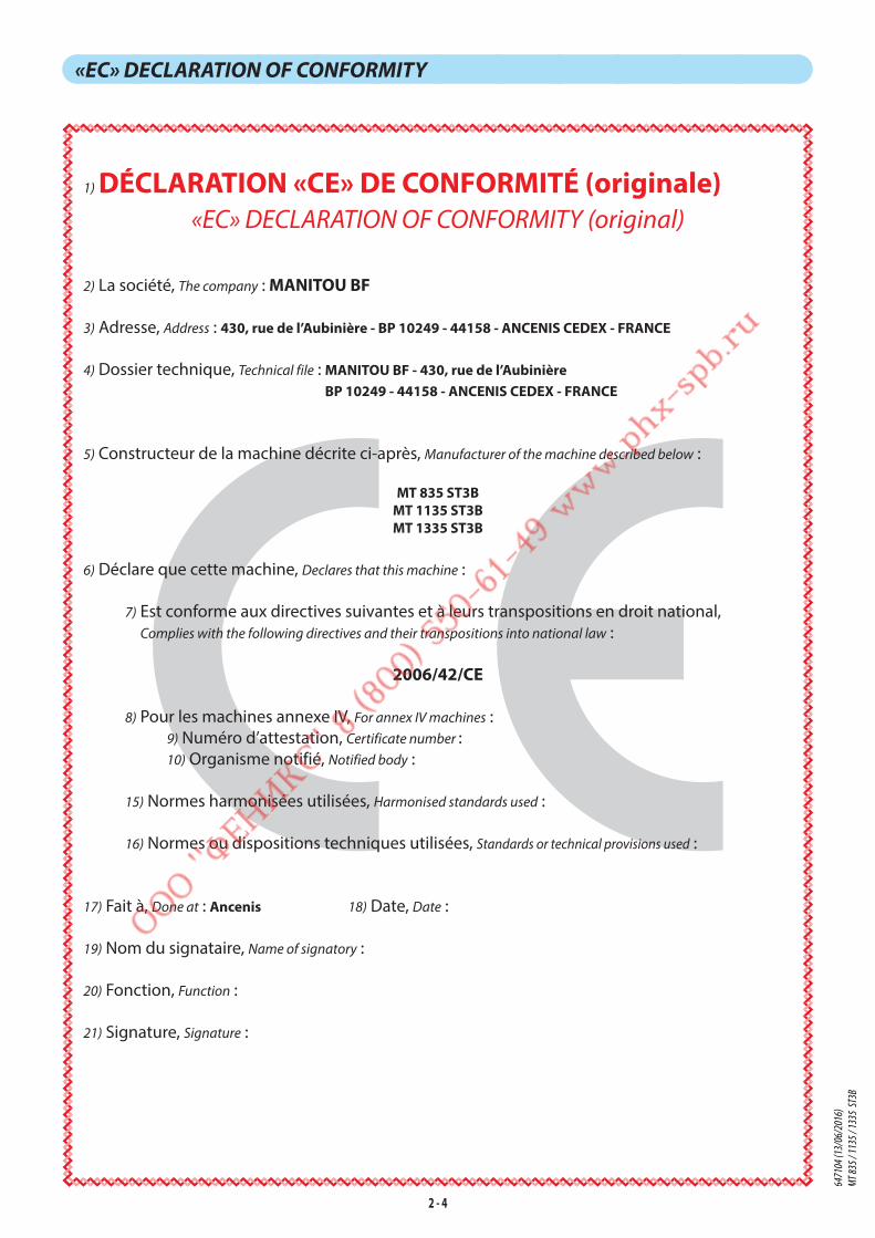
2 - 4
«EC» DECLARATION OF CONFORMITY
1) DÉCLARATION «CE» DE CONFORMITÉ (originale)«EC» DECLARATION OF CONFORMITY (original)
2) La société, The company : MANITOU BF
3) Adresse, Address : 430, rue de l’Aubinière - BP 10249 - 44158 - ANCENIS CEDEX - FRANCE
4) Dossier technique, Technical file : MANITOU BF - 430, rue de l’Aubinière BP 10249 - 44158 - ANCENIS CEDEX - FRANCE
5) Constructeur de la machine décrite ci-après, Manufacturer of the machine described below :
MT 835 ST3BMT 1135 ST3BMT 1335 ST3B
6) Déclare que cette machine, Declares that this machine :
7) Est conforme aux directives suivantes et à leurs transpositions en droit national,
Complies with the following directives and their transpositions into national law :
2006/42/CE
8) Pour les machines annexe IV, For annex IV machines :
9) Numéro d’attestation, Certificate number :
10) Organisme notifié, Notified body :
15) Normes harmonisées utilisées, Harmonised standards used :
16) Normes ou dispositions techniques utilisées, Standards or technical provisions used :
17) Fait à, Done at : Ancenis 18) Date, Date :
19) Nom du signataire, Name of signatory :
20) Fonction, Function :
21) Signature, Signature :
6471
04 (1
3/06
/201
6)
MT 83
5 / 11
35 / 1
335
ST3B

2 - 5
bg : 1) удостоверение за « СЕ » съответствие (oригинална), 2) Фирмата, 3) Адрес, 4) Техническо досие, 5) Фабрикант на описаната по-долу машина, 6) Обявява, че тази машина, 7) Отговаря на следните директиви и на тяхното съответствие национално право, 8) За машините към допълнение IV, 9) Номер на удостоверението, 10) Наименувана фирма, 15) хармонизирани стандарти използвани, 16) стандарти или технически правила, използвани, 17) Изработено в, 18) Дата, 19) Име на разписалия се, 20) Функция, 21) Функция.
cs : 1) ES prohlášení o shodě (původní), 2) Název společnosti, 3) Adresa, 4) Technická dokumentace, 5) Výrobce níže uvedeného stroje, 6) Prohlašuje, že tento stroj, 7) Je v souladu s následujícími směrnicemi a směrnicemi transponovanými do vnitrostátního práva, 8) Pro stroje v příloze IV, 9) Číslo certifikátu, 10) Notifikační orgán, 15) harmonizované normy použity, 16) Norem a technických pravidel používaných, 17) Místo vydání, 18) Datum vydání, 19) Jméno podepsaného, 20) Funkce, 21) Podpis.
da : 1) EF Overensstemmelseserklæring (original), 2) Firmaet, 3) Adresse, 4) tekniske dossier, 5) Konstruktør af nedenfor beskrevne maskine, 6) Erklærer, at denne maskine, 7) Overholder nedennævnte direktiver og disses gennemførelse til national ret, 8) For maskiner under bilag IV, 9) Certifikat nummer, 10) Bemyndigede organ, 15) harmoniserede standarder, der anvendes, 16) standarder eller tekniske regler, 17) Udfærdiget i, 18) Dato, 19) Underskrivers navn, 20) Funktion, 21) Underskrift.
de : 1) EG-Konformitätserklärung (original), 2) Die Firma, 3) Adresse, 4) Technischen Unterlagen, 5) Hersteller der nachfolgend beschriebenen Maschine, 6) Erklärt, dass diese Maschine, 7) den folgenden Richtlinien und deren Umsetzung in die nationale Gesetzgebung entspricht, 8) Für die Maschinen laut Anhang IV, 9) Bescheinigungsnummer, 10) Benannte Stelle, 15) angewandten harmonisierten Normen, 16) angewandten sonstigen technischen Normen und Spezifikationen, 17) Ausgestellt in, 18) Datum, 19) Name des Unterzeichners, 20) Funktion, 21) Unterschrift.
el : 1) Δήλωση συμμόρφωσης CE (πρωτότυπο), 2) Η εταιρεία, 3) Διεύθυνση, 4) τεχνικό φάκελο, 5) Κατασκευάστρια του εξής περιγραφόμενου μηχανήματος, 6) Δηλώνει ότι αυτό το μηχάνημα, 7) Είναι σύμφωνο με τις εξής οδηγίες και τις προσαρμογές τους στο εθνικό δίκαιο, 8) Για τα μηχανήματα παραρτήματος IV, 9) Αριθμός δήλωσης, 10) Κοινοποιημένος φορέας, 15) εναρμονισμένα πρότυπα που χρησιμοποιούνται, 16) Πρότυπα ή τεχνικούς κανόνες που χρησιμοποιούνται, 16) Είναι σύμφωνο με τα εξής πρότυπα και τεχνικές διατάξεις, 17) Εν, 18) Ημερομηνία, 19) Όνομα του υπογράφοντος, 20) Θέση, 21) Υπογραφή.
es : 1)Declaración DE de conformidad (original), 2) La sociedad, 3) Dirección, 4) expediente técnico, 5) Constructor de la máquina descrita a continuación, 6) Declara que esta máquina, 7) Está conforme a las siguientes directivas y a sus transposiciones en derecho nacional, 8) Para las máquinas anexo IV, 9) Número de certificación, 10) Organismo notificado, 15) normas armonizadas utilizadas, 16) Otras normas o especificaciones técnicas utilizadas, 17) Hecho en, 18) Fecha, 19) Nombre del signatario, 20) Función, 21) Firma.
et : 1) EÜ vastavusdeklaratsioon (algupärane), 2) Äriühing, 3) Aadress, 4) Tehniline dokumentatsioon, 5) Seadme tootja, 6) Kinnitab, et see toode, 7) On vastavuses järgmiste direktiivide ja nende riigisisesesse õigusesse ülevõtmiseks vastuvõetud õigusaktidega, 8) IV lisas loetletud seadmete puhul, 9) Tunnistuse number, 10) Sertifitseerimisasutus, 15) kasutatud ühtlustatud standarditele, 16) Muud standardites või spetsifikatsioonides kasutatakse, 17) Väljaandmise koht, 18) Väljaandmise aeg, 19) Allkirjastaja nimi, 20) Amet, 21) Allkiri.
fi : 1) EY-vaatimustenmukaisuusvakuutus (alkuperäiset), 2) Yritys, 3) Osoite, 4) teknisen eritelmän, 5) Jäljessä kuvatun koneen valmistaja, 6) Vakuuttaa, että tämä kone, 7) Täyttää seuraavien direktiivien sekä niitä vastaavien kansallisten säännösten vaatimukset, 8) Liitteen IV koneiden osalta, 9) Todistuksen numero, 10) Ilmoitettu laitos, 15) yhdenmukaistettuja standardeja käytetään, 16) muita standardeja tai eritelmät, 17) Paikka, 18) Aika, 19) Allekirjoittajan nimi, 20) Toimi, 21) Allekirjoitus.
ga : 1) « EC »dearbhú comhréireachta (bunaidh), 2) An comhlacht, 3) Seoladh, 4) comhad teicniúil, 5) Déantóir an innill a thuairiscítear thíos, 6) Dearbhaíonn sé go bhfuil an t-inneall, 7) Go gcloíonn sé le na treoracha seo a leanas agus a trasuímh isteach i ndlí náisiúnta, 8) Le haghaidh innill an aguisín IV, 9) Uimhir teastais, 10) Comhlacht a chuireadh i bhfios, 15) caighdeáin comhchuibhithe a úsáidtear, 16) caighdeáin eile nó sonraíochtaí teicniúla a úsáidtear, 17) Déanta ag, 18) Dáta, 19) Ainm an tsínitheora, 20) Feidhm, 21) Síniú.
hu : 1) CE megfelelőségi nyilatkozat (eredeti), 2) A vállalat, 3) Cím, 4) műszaki dokumentáció, 5) Az alábbi gép gyártója, 6) Kijelenti, hogy a gép, 7) Megfelel az alábbi irányelveknek valamint azok honosított előírásainak, 8) A IV. melléklet gépeihez, 9) Bizonylati szám, 10) Értesített szervezet, 15) felhasznált harmonizált szabványok, 16) egyéb felhasznált műszaki szabványok és előírások hivatkozásai, 17) Kelt (hely), 18) Dátum, 19) Aláíró neve, 20) Funkció, 21) Aláírás.
is : 1) (Samræmisvottorð ESB (upprunalega), 2) Fyrirtækið, 3) Aðsetur, 4) Tæknilegar skrá, 5) Smiður tækisins sem lýst er hér á eftir, 6) Staðfestir að tækið, 7) Samræmist eftirfarandi stöðlum og staðfærslu þeirra með hliðsjón af þjóðarrétti, 8) Fyrir tækin í aukakafla IV, 9) Staðfestingarnúmer, 10) Tilkynnt til, 15) samhæfða staðla sem notaðir, 16) önnur staðlar eða forskriftir notað, 17) Staður, 18) Dagsetning, 19) Nafn undirritaðs, 20) Staða, 21) Undirskrift.
it : 1) Dichiarazione CE di conformità (originale), 2) La società, 3) Indirizzo, 4) fascicolo tecnico, 5) Costruttore della macchina descritta di seguito, 6) Dichiara che questa macchina, 7) È conforme alle direttive seguenti e alle relative trasposizioni nel diritto nazionale, 8) Per le macchine Allegato IV, 9) Numero di Attestazione, 10) Organismo notificato, 15) norme armonizzate applicate, 16) altre norme e specifiche tecniche applicate, 17) Stabilita a, 18) Data, 19) Nome del firmatario, 20) Funzione, 21) Firma.
lt : 1) CE atitikties deklaracija (originalas), 2) Bendrovė, 3) Adresas, 4) Techninė byla, 5) Žemiau nurodytas įrenginio gamintojas, 6) Pareiškia, kad šis įrenginys, 7) Atitinka toliau nurodytas direktyvas ir į nacionalinius teisės aktus perkeltas jų nuostatas, 8) IV priedas dėl mašinų, 9) Sertifikato Nr, 10) Paskelbtoji įstaiga, 15) suderintus standartus naudojamus, 16) Kiti standartai ir technines specifikacijas, 17) Pasirašyta, 18) Data, 19) Pasirašiusio asmens vardas ir pavardė, 20) Pareigos, 21) Parašas.
lv : 1) EK atbilstības deklarācija (oriģināls), 2) Uzņēmums, 3) Adrese, 4) tehniskās lietas, 5) Tālāk aprakstītās iekārtas ražotājs, 6) Apliecina, ka šī iekārta, 7) Ir atbilstoša tālāk norādītajām direktīvām un to transpozīcijai nacionālajā likumdošanā, 8) Iekārtām IV pielikumā, 9) Apliecības numurs, 10) Reģistrētā organizācija, 15) lietotajiem saskaņotajiem standartiem, 16) lietotajiem tehniskajiem standartiem un specifikācijām, 17) Sastādīts, 18) Datums, 19) Parakstītāja vārds, 20) Amats, 21) Paraksts.
mt : 1) Dikjarazzjoni ta’ Konformità KE (oriġinali), 2) Il-kumpanija, 3) Indirizz, 4) fajl tekniku, 5) Manifattriċi tal-magna deskritta hawn isfel, 6) Tiddikjara li din il-magna, 7) Hija konformi hija konformi mad-Direttivi segwenti u l-liġijiet li jimplimentawhom fil-liġi nazzjonali, 8) Għall-magni fl-Anness IV, 9) Numru taċ-ċertifikat, 10) Entità nnotifikata, 15) l-istandards armonizzati użati, 16) standards tekniċi u speċifikazzjonijiet oħra użati, 17) Magħmul f’, 18) Data, 19) Isem il-firmatarju, 20) Kariga, 21) Firma.
nl : 1) EG-verklaring van overeenstemming (oorspronkelijke), 2) Het bedrijf, 3) Adres, 4) technisch dossier, 5) Constructeur van de hierna genoemde machine, 6) Verklaart dat deze machine, 7) In overeenstemming is met de volgende richtlijnen en hun omzettingen in het nationale recht, 8) Voor machines van bijlage IV, 9) Goedkeuringsnummer, 10) Aangezegde instelling, 15) gehanteerde geharmoniseerde normen, 16) andere gehanteerde technische normen en specificaties, 17) Opgemaakt te, 18) Datum, 19) Naam van ondergetekende, 20) Functie, 21) Handtekening.
no : 1) CE-samsvarserklæring (original), 2) Selskapet, 3) Adresse, 4) tekniske arkiv, 5) Fabrikant av følgende maskin, 6) Erklærer at denne maskinen, 7) Oppfyller kravene i følgende direktiver, med nasjonale gjennomføringsbestemmelser, 8) For maskinene i tillegg IV, 9) Attestnummer, 10) Notifisert organ, 15) harmoniserte standarder som brukes, 16) Andre standarder og spesifikasjoner brukt, 17) Utstedt i, 18) Dato, 19) Underskriverens navn, 20) Stilling, 21) Underskrift.
pl : 1) Deklaracja zgodności CE (oryginalne), 2) Spółka, 3) Adres, 4) dokumentacji technicznej, 5) Wykonawca maszyny opisanej poniżej, 6) Oświadcza, że ta maszyna, 7) Jest zgodna z następującymi dyrektywami i odpowiadającymi przepisami prawa krajowego, 8) Dla maszyn załącznik IV, 9) Numer certyfikatu, 10) Jednostka certyfikująca, 15) zastosowanych norm zharmonizowanych, 16) innych zastosowanych norm technicznych i specyfikacji, 17) Sporządzono w, 18) Data, 19) Nazwisko podpisującego, 20) Stanowisko, 21) Podpis.
pt : 1) Declaração de conformidade CE (original), 2) A empresa, 3) Morada, 4) processo técnico, 5) Fabricante da máquina descrita abaixo, 6) Declara que esta máquina, 7) Está em conformidade às directivas seguintes e às suas transposições para o direito nacional, 8) Para as máquinas no anexo IV, 9) Número de certificado, 10) Entidade notificada, 15) normas harmonizadas utilizadas, 16) outras normas e especificações técnicas utilizadas, 17) Elaborado em, 18) Data, 19) Nome do signatário, 20) Cargo, 21) Assinatura.
ro : 1) Declaraţie de conformitate CE (originală), 2) Societatea, 3) Adresa, 4) cărtii tehnice, 5) Constructor al maşinii descrise mai jos, 6) Declară că prezenta maşină, 7) Este conformă cu directivele următoare şi cu transpunerea lor în dreptul naţional, 8) Pentru maşinile din anexa IV, 9) Număr de atestare, 10) Organism notificat, 15) standardele armonizate utilizate, 16) alte standarde si specificatii tehnice utilizate, 17) Întocmit la, 18) Data, 19) Numele persoanei care semnează, 20) Funcţia, 21) Semnătura.
sk : 1) ES vyhlásenie o zhode (pôvodný), 2) Názov spoločnosti, 3) Adresa, 4) technickej dokumentácie, 5) Výrobca nižšie opísaného stroja, 6) Vyhlasuje, že tento stroj, 7) Je v súlade s nasledujúcimi smernicami a smernicami transponovanými do vnútroštátneho práva, 8) Pre stroje v prílohe IV, 9) Číslo certifikátu, 10) Notifikačný orgán, 15) použité harmonizované normy, 16) použité iné technické normy a predpisy, 17) Miesto vydania, 18) Dátum vydania, 19) Meno podpisujúceho, 20) Funkcia, 21) Podpis.
sl : 1) ES Izjava o ustreznosti (izvirna), 2) Družba. 3) Naslov. 4) tehnične dokumentacije, 5) Proizvajalac tukaj opisanega stroja, 6) Izjavlja, da je ta stroj, 7) Ustreza naslednjim direktivam in njihovi transpoziciji v državno pravo, 8) Za stroje priloga IV, 9) Številka potrdila, 10) Obvestilo organu, 15) uporabljene harmonizirane standarde, 16) druge uporabljene tehnične standarde in zahteve, 17) V, 18) Datum, 19) Ime podpisnika, 20) Funkcija, 21) Podpis.
sv : 1) CE-försäkran om överensstämmelse (original), 2) Företaget, 3) Adress, 4) tekniska dokumentationen, 5) Konstruktör av nedan beskrivna maskin, 6) Försäkrar att denna maskin, 7) Överensstämmer med nedanstående direktiv och införlivandet av dem i nationell rätt, 8) För maskinerna i bilaga IV, 9) Nummer för godkännande, 10) Organism som underrättats, 15) Harmoniserade standarder som använts, 16) andra tekniska standarder och specifikationer som använts, 17) Upprättat i, 18) Datum, 19) Namn på den som undertecknat, 20) Befattning, 21) Namntecknin.
6471
04 (1
3/06
/201
6)
MT 83
5 / 11
35 / 1
335
ST3B
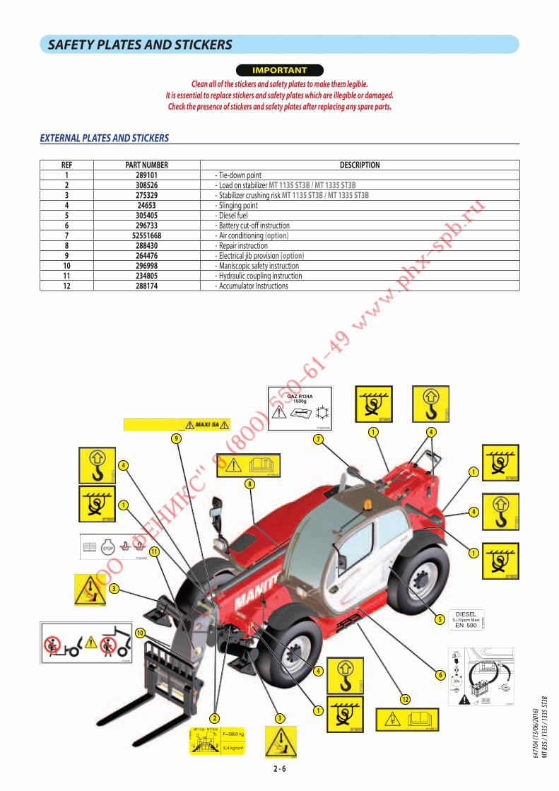
2 - 6
SAFETY PLATES AND STICKERS
IMPORTANT
Clean all of the stickers and safety plates to make them legible.
It is essential to replace stickers and safety plates which are illegible or damaged.
Check the presence of stickers and safety plates after replacing any spare parts.
EXTERNAL PLATES AND STICKERS
REF PART NUMBER DESCRIPTION1 289101 - Tie-down point2 308526 - Load on stabilizer MT 1135 ST3B / MT 1335 ST3B3 275329 - Stabilizer crushing risk MT 1135 ST3B / MT 1335 ST3B4 24653 - Slinging point5 305405 - Diesel fuel6 296733 - Battery cut-off instruction7 52551668 - Air conditioning (option)8 288430 - Repair instruction9 264476 - Electrical jib provision (option)
10 296998 - Maniscopic safety instruction11 234805 - Hydraulic coupling instruction12 288174 - Accumulator Instructions
FF
MT1135 - MT1335
N°3
0852
6
F=5800 kg
5,4 kg/cm²
7
3
3
9
11
1
4
4
1
1
5
N°3
0540
5
DIESELS=10ppm Maxi
EN 590
STOP
OFF
30s
ON
OFF
ON
OFF
N°308523
12V/900A
6
8
4
1
1
4
10
2N° 288174
12
GAZ R134A1500g
N°52551668
6471
04 (1
3/06
/201
6)
MT 83
5 / 11
35 / 1
335
ST3B

2 - 7
STICKERS AND PLATES UNDER THE ENGINE HOOD
REF PART NUMBER DESCRIPTION1 259398 - Water/diesel separator2 52501046 - Anti-freeze3 306583 - Engine fuse4 296741 - "Do not mount" safety instruction
3
2
1
4
6471
04 (1
3/06
/201
6)
MT 83
5 / 11
35 / 1
335
ST3B
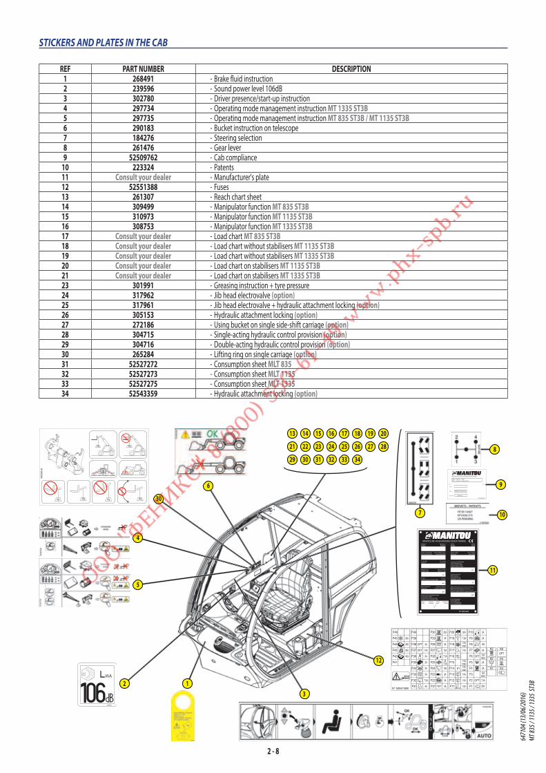
2 - 8
STICKERS AND PLATES IN THE CAB
REF PART NUMBER DESCRIPTION1 268491 - Brake fluid instruction2 239596 - Sound power level 106dB3 302780 - Driver presence/start-up instruction4 297734 - Operating mode management instruction MT 1335 ST3B5 297735 - Operating mode management instruction MT 835 ST3B / MT 1135 ST3B6 290183 - Bucket instruction on telescope7 184276 - Steering selection8 261476 - Gear lever9 52509762 - Cab compliance
10 223324 - Patents11 Consult your dealer - Manufacturer's plate12 52551388 - Fuses13 261307 - Reach chart sheet14 309499 - Manipulator function MT 835 ST3B15 310973 - Manipulator function MT 1135 ST3B16 308753 - Manipulator function MT 1335 ST3B17 Consult your dealer - Load chart MT 835 ST3B18 Consult your dealer - Load chart without stabilisers MT 1135 ST3B19 Consult your dealer - Load chart without stabilisers MT 1335 ST3B20 Consult your dealer - Load chart on stabilisers MT 1135 ST3B21 Consult your dealer - Load chart on stabilisers MT 1335 ST3B23 301991 - Greasing instruction + tyre pressure24 317962 - Jib head electrovalve (option)25 317961 - Jib head electrovalve + hydraulic attachment locking (option)26 305153 - Hydraulic attachment locking (option)27 272186 - Using bucket on single side-shift carriage (option)28 304715 - Single-acting hydraulic control provision (option)29 304716 - Double-acting hydraulic control provision (option)30 265284 - Lifting ring on single carriage (option)31 52527272 - Consumption sheet MLT 83532 52527273 - Consumption sheet MLT 113533 52527275 - Consumption sheet MLT 133534 52543359 - Hydraulic attachment locking (option)
3
4
30
5
6
MANITOU BF 44158 ANCENIS CEDEX FRANCE
N°295449
MODELEMODEL
MODELLOMODELO
SERIESERIES
Année de fabricationYear of manufacture
Anno di fabbricazioneAño de fabricación
N° de sérieSerial Nr
N° di serieN° de serie
Masse à videUnladen mass
Massa a vuotoMasa en vacio
P.T.R.A.Authorized gross vehicle weight
P.T.C.A.P.T.R.A.
Effort de tractionDrag strain
Sforzo di trazioneEsfuerzo de tracción
Pression des pneumatiques (Bar)Tyres pressure (Bar)Pressione dei pneumatici (Bar)Presión de los neumáticos (Bar)
Anno modelloAño modelo
Année modèleModel year
SERIESERIE
AvantFront
AnterioreAdelante
ArrièreRear
PosterioreTrasero
Puissance ISO/TR14396Power ISO/TR14396Potenza ISO/TR14396Potencia ISO/TR14396
kW
Capacité nominaleRated capacityCapacità nominaleCapacidad nominal
kg
Effort vertical maxi. (sur crochet de remorquage)
Maximum vertical force (on trailer hook)
Sforzo verticale massimo (sul gancia di traino)
Esfuerzo vertical máximo (sobre gancho de remolque)
N° d'homologationHomologation NrN° di omologazioneN° de homologación
daN
kg
daN
daN
11
8
7
MANITOU BF 44158 ANCENIS CEDEX FRANCE
ROPS - ISO3471 : 2008
FOPS - ISO3449 : 2008 LEVEL 2
MT835-MT1135-MT1335
9500 kg
N°52509762
YEAR :
MODEL :
MAX MASS :
9
10
1
F10
F9
F8
F7
F6
F5
F4
F3
F2
F1F11
F12
F13
F14
F15
F16
F17
F18
F19
F20F30
F29
F28
F27
F26
F25
F24
F23
F22
F21F31
F32
F33
F34
F35
F36
F37
F38
F39
F40
F41
F42
F43
F44
F45
F46
K3
K2
K1
K6
K5
K4
ECU
50A
40A
30A
40A
15Amaxi
15Amaxi
20A
7.5A
15A
10A
15A
10A
maxi15A
15A
2A
5A
7.5A
5A
2A
2A maxi
7.5A
2A
2A
15A
2A
15A
2A
2A
maxi15A
20A3A
3A
3A
2A
15A
2A
7.5A
7.5A
5A
25A
15A
OPTOPT
OPT
OPT
3AOPT
K1
MP1
MP2
N° 52551388
Diagn
Diagn
1
2
3
4
5
67
8
9*
0
#
Pn
1
2
3
4
5
67
8
9*
0
#
12
239596
N°265284
KgKg KgKg
Kg Kg Kg Kg Kg Kg
Kg Kg
Kg
2
13
23
14
24
15
25 27 28
33
16
26
17 19 20
29
18
30
21
31 32 34
22
6471
04 (1
3/06
/201
6)
MT 83
5 / 11
35 / 1
335
ST3B

2 - 9
2827 29
23
13
N°309499
N°309499
MT835
SUIVANT NORME EN 1459 annexe B.
50° 60° 68°D
C
B
A
8
7
6
5
4
3
2
1
0m
40°
30°
20°
10°
0°
-3°
7.75
D C B A 0.5m
5 4 3 2 1 0m
3500
KG30
00KG
2500
KG
2000
KG
1500
KG
1200
KG
1150
KG
4.25 1.502.95 1.954.45 3.70 2.45 1.70
1714
N°310973
SUIVANT NORME EN 1459 annexe B.
N°310973
MT1135
68°60°50°
40°
30°
20°
10°
0°-3°
10.75
10
8 7 6 5 4 3 2
0
1
2
3
4
5
6
7
8
9
0m1-1
11
2.052.35
2.803.35
4.155.356.857.75
0.5m
E
D
C
B
A
400
KG 60
0 K
G 1000
KG
1500
KG
2000
KG
3000
KG
2500
KG
3500
KG
1815
N°308753
N°308753
MT 1335
SUIVANT NORME EN 1459 annexe B.
50°
20°
10°
0°
30°
40°
-3°
60° 71°
410
13
9
0
1
2
3
4
5
6
7
8
9
10
11
12
14
0m1235678-1
12.30
7.30
2.55
3.05 1.852.253.65
4.255.10
5.606.358.25
8.75
3000KG
300K
G 400K
G 600K
G 1000
KG12
00KG
1600
KG20
00KG
2500
KG
800K
G
3500KG
E
D
C
B
A
1916
N°310977
SUIVANT NORME EN 1459 annexe B.
0
10
8 7 6 5 4 3
1
2
3
4
5
6
7
8
9
-1
11
2 1 0m
3500
KG
3000
KG
2500
KG
2000
KG
1600
KG
1200
KG
D
C
B
A
E
0.5m
7.606.50
5.65
4.854.25
3.75
50°
1°
10°
20°
30°
40°
60° 72°
11.05
MT 1135MT 1135 HMT 1135 HA
MT 1335MT 1335 HMT 1335 HA
N°301819
SUIVANT NORME EN 1459 annexe B.
4.555.858.051.805.206.758.75
3000
KG 35
00K
G
2000
KG
2500
KG
1200
KG
1600
KG
1000
KG
E
D
C
B
A
13
14
12
11
10
9
8
7
6
5
4
3
2
1
0
-1
50° 60° 70° 75°
12.55
8 7 6 5 4 3 2 1 0m910
0.5m
40°
30°
20°
10°
1°
2120
N°317962
N°317962
24
N°317961
N°317961
25
31
32
33
26
1er Montage
N°52543359
34
2ème Montage 6471
04 (1
3/06
/201
6)
MT 83
5 / 11
35 / 1
335
ST3B
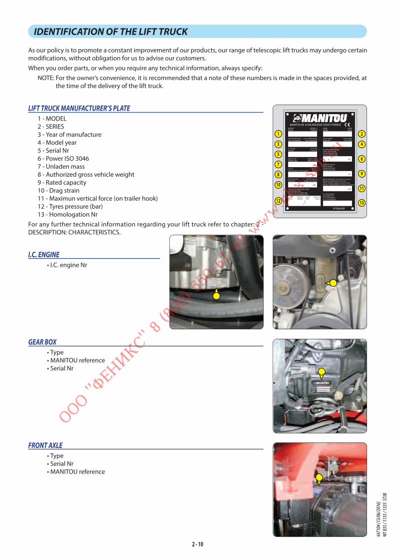
2 - 10
IDENTIFICATION OF THE LIFT TRUCK
As our policy is to promote a constant improvement of our products, our range of telescopic lift trucks may undergo certain
modifications, without obligation for us to advise our customers.
When you order parts, or when you require any technical information, always specify:
NOTE: For the owner’s convenience, it is recommended that a note of these numbers is made in the spaces provided, at
the time of the delivery of the lift truck.
LIFT TRUCK MANUFACTURER’S PLATE
1 - MODEL
2 - SERIES
3 - Year of manufacture
4 - Model year
5 - Serial Nr
6 - Power ISO 3046
7 - Unladen mass
8 - Authorized gross vehicle weight
9 - Rated capacity
10 - Drag strain
11 - Maximun vertical force (on trailer hook)
12 - Tyres pressure (bar)
13 - Homologation Nr
For any further technical information regarding your lift truck refer to chapter: 2 -
DESCRIPTION: CHARACTERISTICS.
I.C. ENGINE
• I.C. engine Nr
GEAR BOX
• Type
• MANITOU reference
• Serial Nr
FRONT AXLE
• Type
• Serial Nr
• MANITOU reference
MANITOU BF 44158 ANCENIS CEDEX FRANCE
N°295449
MODELEMODEL
MODELLOMODELO
SERIESERIES
Année de fabricationYear of manufacture
Anno di fabbricazioneAño de fabricación
N° de sérieSerial Nr
N° di serieN° de serie
Masse à videUnladen mass
Massa a vuotoMasa en vacio
P.T.R.A.Authorized gross vehicle weight
P.T.C.A.P.T.R.A.
Effort de tractionDrag strain
Sforzo di trazioneEsfuerzo de tracción
Pression des pneumatiques (Bar)Tyres pressure (Bar)Pressione dei pneumatici (Bar)Presión de los neumáticos (Bar)
Anno modelloAño modelo
Année modèleModel year
SERIESERIE
AvantFront
AnterioreAdelante
ArrièreRear
PosterioreTrasero
Puissance ISO/TR14396Power ISO/TR14396Potenza ISO/TR14396Potencia ISO/TR14396
kW
Capacité nominaleRated capacityCapacità nominaleCapacidad nominal
kg
Effort vertical maxi. (sur crochet de remorquage)
Maximum vertical force (on trailer hook)
Sforzo verticale massimo (sul gancia di traino)
Esfuerzo vertical máximo (sobre gancho de remolque)
N° d'homologationHomologation NrN° di omologazioneN° de homologación
daN
kg
daN
daN
1 2
3 4
6
9
11
13
5
7
8
10
12
6471
04 (1
3/06
/201
6)
MT 83
5 / 11
35 / 1
335
ST3B
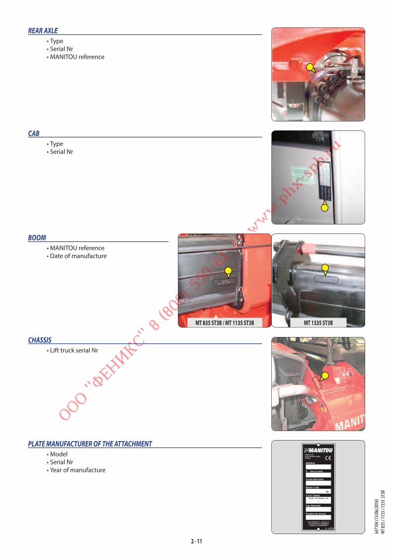
2 - 11
REAR AXLE
• Type
• Serial Nr
• MANITOU reference
CAB
• Type
• Serial Nr
BOOM
• MANITOU reference
• Date of manufacture
CHASSIS
• Lift truck serial Nr
PLATE MANUFACTURER OF THE ATTACHMENT
• Model
• Serial Nr
• Year of manufacture
N 207701
MODELE
N dans la série
Année fabrication
Masse à vide
C d G / Tablier
Cap. Nominale
Pression de service
AVERTISSEMENT : RESPECTEZLA CAPACITE DE L'ENSEMBLE"CHARIOT ET EQUIPEMENT"
kg
A vide / En charge : mm
MANITOU BF44158 ANCENIS CEDEXFRANCE
MT 1335 ST3BMT 835 ST3B / MT 1135 ST3B
6471
04 (1
3/06
/201
6)
MT 83
5 / 11
35 / 1
335
ST3B

2 - 12
CHARACTERISTICS MT 835 ST3B
I.C. ENGINEType PERKINS 854E-E34TA JR51746Fuel DieselNumber of cylinders 4 in lineSuction SuperchargedInjection system DirectIgnition sequence 1.3.4.2Capacity cm3 3400Bore and stroke mm 99 x 110Compression ratio 17:1Nominal speed laden rpm 2200Idling speed slow unladen rpm 850Max. speed unladen rpm 2350Power ISO/TR 3046 cv - kW 102 - 75Power SAE J 1995 cv - kW 102 - 75Maximum torque ISO/TR 3046 Nm 420 to 1400 rpmGravimetric efficiency ISO 5011 % 99,9Type of cooling By waterFan Puller
TRANSMISSIONGear box DANA
- Type Mechanical - Forward/reverse selector Electro-hydraulic - Torque converter DANA - Number of forward speeds 4 - Number of reverse speeds 4
Angle gear box -Front axle DANA
- Differential Without lockingRear axle DANA
- Differential Without lockingDrive wheels 4RM Permanent
- Switch for 2/4 drive wheels NoFront tyres MICHELIN
- Size 400/80-24 156A8 POWER CL - Pressure bar 4
Rear tyres MICHELIN - Size 400/80-24 156A8 POWER CL - Pressure bar 4
ELECTRIC CIRCUIT
BatterySTANDARD 12 V - 110 Ah - 900 A EN
OPTION 12 V - 180 Ah - 1200 A ENAlternator 12 V - 100 A
- Type ISKRA AAK-EFStarter 12 V - 3,2 kW
- Type ISKRA AZE
BRAKE CIRCUITService brake Hydraulic power brake
- Type of brake Multidisk brake immersed in oil - Type of control Foot-operated for the front and rear axles
Parking brake Low pressure brake - Type of brake Disk on gear-box output - Type of control Electro-hydraulic
SOUND AND VIBRATIONSound pressure level in the driver's cab LpA
(according to standard NF EN 12053) dB(A) 82 (cab closed) ; xx (cab open)
Sound pressure (according to directive2009/76) dB(A) xx (cab closed) ; xx (cab open)Sound pressure level ensured in the LwA environment
(according to directive 2000/14/EC modified by directive 2005/88/EC) dB(A) 105 (measured) ; 106 (ensured)
Sound level in motion (according to directive 2009/63) dB(A) xxAverage weighted acceleration on driver's body
(according to standard NF EN 13059) m/s2 2
The average weighted acceleration transmitted to the driver's hand/
arm system (according to standard ISO 5349-2) m/s2 < 2,5
Standard seat vibration m/s2 xx (lightweight operator) ; xx (heavyweight operator) 6471
04 (1
3/06
/201
6)
MT 83
5 / 11
35 / 1
335
ST3B

2 - 13
HYDRAULIC CIRCUITHydraulic pump
- Type Gear pump with flow divider on 2nd casing1st casing 2nd casing
- Capacity cm3 31 22 - Max. rating capacity unladen l/mn 73 52 - Flow rate at 1600 rpm l/mn 50 35
Filtration - Return μm 10 10 - Suction μm 135 135
Maximum service pressure bar 270 - Telescoping circuit bar 200 / 270 - Lifting circuit bar 280 / 280 - Tilt circuit bar 280 / 200 - Stabilizers Circuit bar 270 - Tilting corrector circuit bar 140 - Attachment circuit bar 270 - Steering circuit bar 140
HYDRAULIC MOVEMENTSLongitudinal stability limiter and warning device ElectronicLifting motions (boom retracted)
- Unladen lifting s - m/mn 6,6 - 45,5 - Laden lifting s - m/mn 11,0 - 27,3 - Unladen lowering s - m/mn 6 - 50 - Laden lowering s - m/mn 5 - 60
Telescoping motions (boom raised) - Unladen extending s - m/mn 6 - 29,8 - Laden extending s - m/mn 6 - 29,8 - Unladen retracting s - m/mn 5,6 - 31,9 - Laden retracting s - m/mn 5,2 - 34,3
Tilting movements - Unladen digging s - °/s 3,2 - 39,4 - Forward tilting unladen s - °/s 3 - 42,1
SPECIFICATIONS AND WEIGHTSSpeed of movement for lift truck in standard configuration on flat
ground (except particular conditions)Front unladen 1 km/h 5,1
2 km/h 8,13 km/h 15,24 km/h 25,7
Rear unladen 1 km/h 5,12 km/h 8,13 km/h 15,24 km/h 25,7
Standard attachment TFF35 MT1040 - Weight with forks kg 160 - Weight of forks (each one) kg 70
Rated capacity with standard attachment kg 3500Distance from the centre of gravity from the load to the lug of the forks mm 500Standard lifting height mm 7750Lift truck weight without attachment kg 6895Lift truck weight with standard attachment
- Unladen kg 7195 - At rated load kg 10695
Weight per axle with standard attachment (transport position) - Front unladen kg 3455 - Rear unladen kg 3740 - Front rated load kg 9535 - Rear rated load kg 1160
Weight per axle with standard attachment (boom extended) - Front rated load kg 7725 - Rear rated load kg 620
Drag strain on the coupling hook - Unladen (sliding) daN 6190 - At rated load (transmission setting) daN 8230
Pull strain with open carrier (according to standard ISO 8313) daN 6264
6471
04 (1
3/06
/201
6)
MT 83
5 / 11
35 / 1
335
ST3B
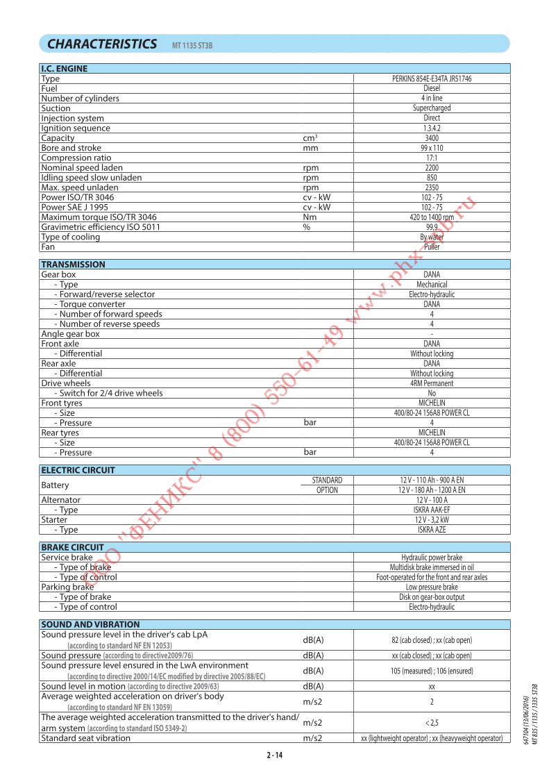
2 - 14
CHARACTERISTICS MT 1135 ST3B
I.C. ENGINEType PERKINS 854E-E34TA JR51746Fuel DieselNumber of cylinders 4 in lineSuction SuperchargedInjection system DirectIgnition sequence 1.3.4.2Capacity cm3 3400Bore and stroke mm 99 x 110Compression ratio 17:1Nominal speed laden rpm 2200Idling speed slow unladen rpm 850Max. speed unladen rpm 2350Power ISO/TR 3046 cv - kW 102 - 75Power SAE J 1995 cv - kW 102 - 75Maximum torque ISO/TR 3046 Nm 420 to 1400 rpmGravimetric efficiency ISO 5011 % 99,9Type of cooling By waterFan Puller
TRANSMISSIONGear box DANA
- Type Mechanical - Forward/reverse selector Electro-hydraulic - Torque converter DANA - Number of forward speeds 4 - Number of reverse speeds 4
Angle gear box -Front axle DANA
- Differential Without lockingRear axle DANA
- Differential Without lockingDrive wheels 4RM Permanent
- Switch for 2/4 drive wheels NoFront tyres MICHELIN
- Size 400/80-24 156A8 POWER CL - Pressure bar 4
Rear tyres MICHELIN - Size 400/80-24 156A8 POWER CL - Pressure bar 4
ELECTRIC CIRCUIT
BatterySTANDARD 12 V - 110 Ah - 900 A EN
OPTION 12 V - 180 Ah - 1200 A ENAlternator 12 V - 100 A
- Type ISKRA AAK-EFStarter 12 V - 3,2 kW
- Type ISKRA AZE
BRAKE CIRCUITService brake Hydraulic power brake
- Type of brake Multidisk brake immersed in oil - Type of control Foot-operated for the front and rear axles
Parking brake Low pressure brake - Type of brake Disk on gear-box output - Type of control Electro-hydraulic
SOUND AND VIBRATIONSound pressure level in the driver's cab LpA
(according to standard NF EN 12053) dB(A) 82 (cab closed) ; xx (cab open)
Sound pressure (according to directive2009/76) dB(A) xx (cab closed) ; xx (cab open)Sound pressure level ensured in the LwA environment
(according to directive 2000/14/EC modified by directive 2005/88/EC) dB(A) 105 (measured) ; 106 (ensured)
Sound level in motion (according to directive 2009/63) dB(A) xxAverage weighted acceleration on driver's body
(according to standard NF EN 13059) m/s2 2
The average weighted acceleration transmitted to the driver's hand/
arm system (according to standard ISO 5349-2) m/s2 < 2,5
Standard seat vibration m/s2 xx (lightweight operator) ; xx (heavyweight operator) 6471
04 (1
3/06
/201
6)
MT 83
5 / 11
35 / 1
335
ST3B
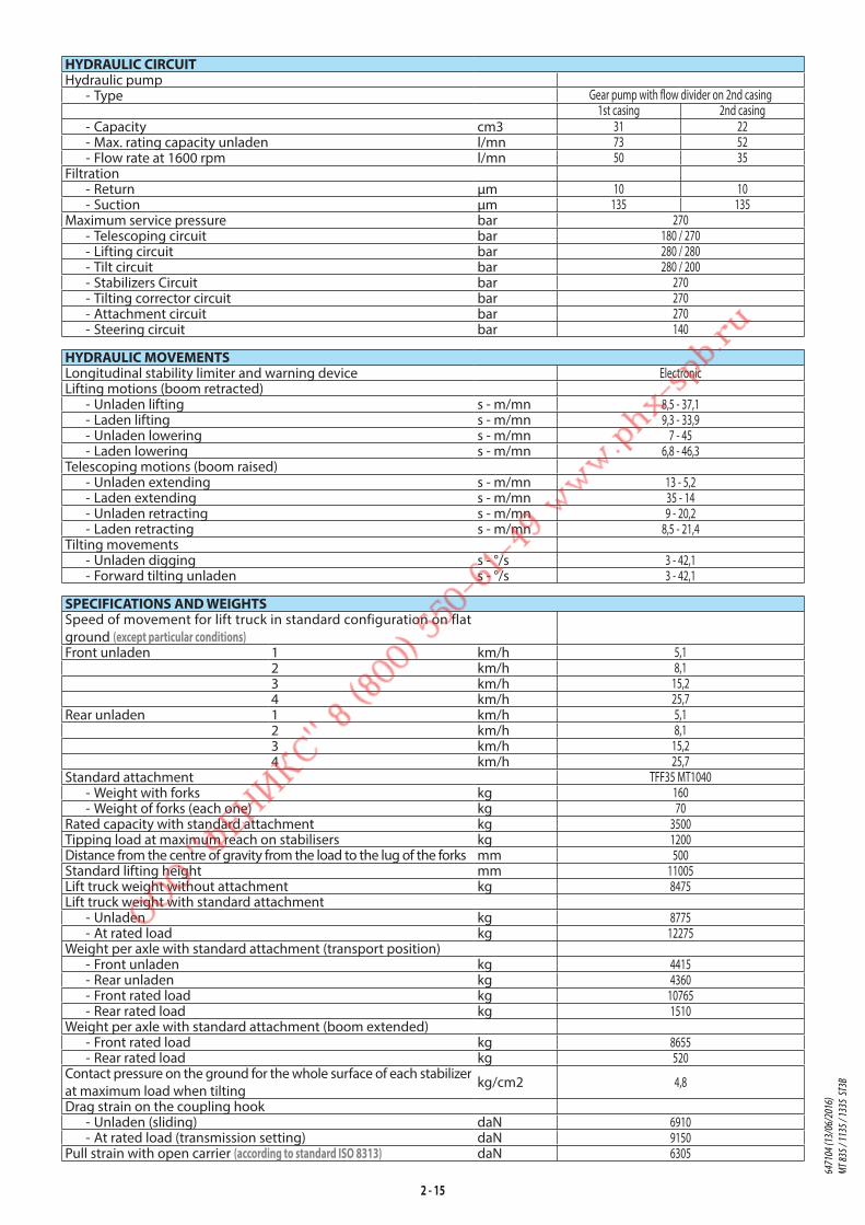
2 - 15
HYDRAULIC CIRCUITHydraulic pump
- Type Gear pump with flow divider on 2nd casing1st casing 2nd casing
- Capacity cm3 31 22 - Max. rating capacity unladen l/mn 73 52 - Flow rate at 1600 rpm l/mn 50 35
Filtration - Return μm 10 10 - Suction μm 135 135
Maximum service pressure bar 270 - Telescoping circuit bar 180 / 270 - Lifting circuit bar 280 / 280 - Tilt circuit bar 280 / 200 - Stabilizers Circuit bar 270 - Tilting corrector circuit bar 270 - Attachment circuit bar 270 - Steering circuit bar 140
HYDRAULIC MOVEMENTSLongitudinal stability limiter and warning device ElectronicLifting motions (boom retracted)
- Unladen lifting s - m/mn 8,5 - 37,1 - Laden lifting s - m/mn 9,3 - 33,9 - Unladen lowering s - m/mn 7 - 45 - Laden lowering s - m/mn 6,8 - 46,3
Telescoping motions (boom raised) - Unladen extending s - m/mn 13 - 5,2 - Laden extending s - m/mn 35 - 14 - Unladen retracting s - m/mn 9 - 20,2 - Laden retracting s - m/mn 8,5 - 21,4
Tilting movements - Unladen digging s - °/s 3 - 42,1 - Forward tilting unladen s - °/s 3 - 42,1
SPECIFICATIONS AND WEIGHTSSpeed of movement for lift truck in standard configuration on flat
ground (except particular conditions)Front unladen 1 km/h 5,1
2 km/h 8,13 km/h 15,24 km/h 25,7
Rear unladen 1 km/h 5,12 km/h 8,13 km/h 15,24 km/h 25,7
Standard attachment TFF35 MT1040 - Weight with forks kg 160 - Weight of forks (each one) kg 70
Rated capacity with standard attachment kg 3500Tipping load at maximum reach on stabilisers kg 1200Distance from the centre of gravity from the load to the lug of the forks mm 500Standard lifting height mm 11005Lift truck weight without attachment kg 8475Lift truck weight with standard attachment
- Unladen kg 8775 - At rated load kg 12275
Weight per axle with standard attachment (transport position) - Front unladen kg 4415 - Rear unladen kg 4360 - Front rated load kg 10765 - Rear rated load kg 1510
Weight per axle with standard attachment (boom extended) - Front rated load kg 8655 - Rear rated load kg 520
Contact pressure on the ground for the whole surface of each stabilizer
at maximum load when tiltingkg/cm2 4,8
Drag strain on the coupling hook - Unladen (sliding) daN 6910 - At rated load (transmission setting) daN 9150
Pull strain with open carrier (according to standard ISO 8313) daN 6305
6471
04 (1
3/06
/201
6)
MT 83
5 / 11
35 / 1
335
ST3B

2 - 16
CHARACTERISTICS MT 1335 ST3B
I.C. ENGINEType PERKINS 854E-E34TA JR51746Fuel DieselNumber of cylinders 4 in lineSuction SuperchargedInjection system DirectIgnition sequence 1.3.4.2Capacity cm3 3400Bore and stroke mm 99 x 110Compression ratio 17:1Nominal speed laden rpm 2200Idling speed slow unladen rpm 850Max. speed unladen rpm 2350Power ISO/TR 3046 cv - kW 102 - 75Power SAE J 1995 cv - kW 102 - 75Maximum torque ISO/TR 3046 Nm 420 to 1400 rpmGravimetric efficiency ISO 5011 % 99,9Type of cooling By waterFan Puller
TRANSMISSIONGear box DANA
- Type Mechanical - Forward/reverse selector Electro-hydraulic - Torque converter DANA - Number of forward speeds 4 - Number of reverse speeds 4
Angle gear box -Front axle DANA
- Differential Without lockingRear axle DANA
- Differential Without lockingDrive wheels 4RM Permanent
- Switch for 2/4 drive wheels NoFront tyres MICHELIN
- Size 400/80-24 156A8 POWER CL - Pressure bar 4
Rear tyres MICHELIN - Size 400/80-24 156A8 POWER CL - Pressure bar 4
ELECTRIC CIRCUIT
BatterySTANDARD 12 V - 110 Ah - 900 A EN
OPTION 12 V - 180 Ah - 1200 A ENAlternator 12 V - 100 A
- Type ISKRA AAK-EFStarter 12 V - 3,2 kW
- Type ISKRA AZE
BRAKE CIRCUITService brake Hydraulic power brake
- Type of brake Multidisk brake immersed in oil - Type of control Foot-operated for the front and rear axles
Parking brake Low pressure brake - Type of brake Disk on gear-box output - Type of control Electro-hydraulic
SOUND AND VIBRATIONSound pressure level in the driver's cab LpA
(according to standard NF EN 12053) dB(A) 82 (cab closed) ; xx (cab open)
Sound pressure (according to directive2009/76) dB(A) xx (cab closed) ; xx (cab open)Sound pressure level ensured in the LwA environment
(according to directive 2000/14/EC modified by directive 2005/88/EC) dB(A) 105 (measured) ; 106 (ensured)
Sound level in motion (according to directive 2009/63) dB(A) xxAverage weighted acceleration on driver's body
(according to standard NF EN 13059) m/s2 2
The average weighted acceleration transmitted to the driver's hand/
arm system (according to standard ISO 5349-2) m/s2 < 2,5
Standard seat vibration m/s2 xx (lightweight operator) ; xx (heavyweight operator) 6471
04 (1
3/06
/201
6)
MT 83
5 / 11
35 / 1
335
ST3B

2 - 17
HYDRAULIC CIRCUITHydraulic pump
- Type Gear pump with flow divider on 2nd casing1st casing 2nd casing
- Capacity cm3 31 22 - Max. rating capacity unladen l/mn 73 52 - Flow rate at 1600 rpm l/mn 50 35
Filtration - Return μm 10 10 - Suction μm 135 135
Maximum service pressure bar 270 - Telescoping circuit bar 180 / 270 - Lifting circuit bar 280 / 280 - Tilt circuit bar 280 / 200 - Stabilizers Circuit bar 270 - Tilting corrector circuit bar 270 - Attachment circuit bar 270 - Steering circuit bar 140
HYDRAULIC MOVEMENTSLongitudinal stability limiter and warning device ElectronicLifting motions (boom retracted)
- Unladen lifting s - m/mn 9,8 - 36,1 - Laden lifting s - m/mn 10,4 - 34 - Unladen lowering s - m/mn 8,2 - 43,2 - Laden lowering s - m/mn 8,2 - 43,2
Telescoping motions (boom raised) - Unladen extending s - m/mn 14,2 - 13,6 - Laden extending s - m/mn 15,4 - 14,8 - Unladen retracting s - m/mn 9,7 - 21,6 - Laden retracting s - m/mn 11,1 - 18,9
Tilting movements - Unladen digging s - °/s 2,7 - 46,7 - Forward tilting unladen s - °/s 2,8 - 45,1
SPECIFICATIONS AND WEIGHTSSpeed of movement for lift truck in standard configuration on flat
ground (except particular conditions)Front unladen 1 km/h 5,1
2 km/h 8,13 km/h 15,24 km/h 25,7
Rear unladen 1 km/h 5,12 km/h 8,13 km/h 15,24 km/h 25,7
Standard attachment TFF35 MT1040 - Weight with forks kg 160 - Weight of forks (each one) kg 70
Rated capacity with standard attachment kg 3500Tipping load at maximum reach on stabilisers kg 1000Distance from the centre of gravity from the load to the lug of the forks mm 500Standard lifting height mm 12550Lift truck weight without attachment kg 8780Lift truck weight with standard attachment
- Unladen kg 9080 - At rated load kg 12580
Weight per axle with standard attachment (transport position) - Front unladen kg 4380 - Rear unladen kg 4700 - Front rated load kg 10910 - Rear rated load kg 1670
Weight per axle with standard attachment (boom extended) - Front rated load kg 8980 - Rear rated load kg 400
Contact pressure on the ground for the whole surface of each stabilizer
at maximum load when tiltingkg/cm2 4,8
Drag strain on the coupling hook - Unladen (sliding) daN 7400 - At rated load (transmission setting) daN 9800
Pull strain with open carrier (according to standard ISO 8313) daN 6346
6471
04 (1
3/06
/201
6)
MT 83
5 / 11
35 / 1
335
ST3B

2 - 18
TIRES
PRESSURE (bar)
TYRE LOAD (kg)FRONT UNLADEN FRONT LADEN REAR UNLADEN REAR LADEN
MT 835 ST3BMICHELIN 400/80-24 156A8 POWER CL 4
1750 4750 1850 600ALLIANCE 400/80-R24 A325 162A8 4
MT 1135 ST3BMICHELIN 400/80-24 156A8 POWER CL 4
2200 5400 2200 750ALLIANCE 400/80-R24 A325 162A8 4
MT 1335 ST3BMICHELIN 400/80-24 156A8 POWER CL 4
2200 5450 2350 850ALLIANCE 400/80-R24 A325 162A8 4
PRESSURE (bar)
LOAD(kg)
PRESSURE ON THE CONTACT SURFACE (kg/cm2)
AREA OF THE CONTACT SURFACE (cm2)
HARD SOIL LOOSE SOIL HARD SOIL LOOSE SOIL
MICHELIN 460/70-R24 XMCL 159A8 4
600 6,67 2,55 90 235750 7,06 2,69 106 277850 7,33 2,79 116 305
1750 8,93 3,33 196 5251850 9,02 3,38 205 5472200 9,48 3,53 232 6232350 9,67 3,59 243 6554750 11,70 4,28 406 11115400 12,11 4,41 446 12235450 12,14 4,42 449 1232
ALLIANCE 400/80-R24 A325 162A8 4
600750850
1750185022002350475054005450
6471
04 (1
3/06
/201
6)
MT 83
5 / 11
35 / 1
335
ST3B

2 - 19
6471
04 (1
3/06
/201
6)
MT 83
5 / 11
35 / 1
335
ST3B
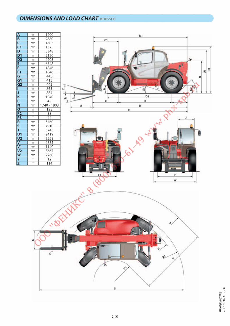
2 - 20
DIMENSIONS AND LOAD CHART MT 835 ST3B
A mm 1200B mm 2880C mm 1603C1 mm 1375D mm 5348D1 mm 5120D2 mm 4203E mm 6548F mm 1846F1 mm 1846G mm 445G1 mm 415G2 mm 445I mm 865J mm 884K mm 1040L mm 45N mm 1740 - 1803O mm 125P2 ° 38P3 ° 44R mm 3460S mm 7910T mm 3745U1 mm 2419U2 mm 2559V mm 4885V1 mm 1140V2 mm 3667W mm 2260Y ° 12Z ° 114
6471
04 (1
3/06
/201
6)
MT 83
5 / 11
35 / 1
335
ST3B

2 - 21
N°309499
MT835
SUIVANT NORME EN 1459 annexe B.
50° 60° 68°D
C
B
A
8
7
6
5
4
3
2
1
0m
40°
30°
20°
10°
0°
-3°
7.75
D C B A 0.5m
5 4 3 2 1 0m
3500
KG30
00KG
2500
KG
2000
KG
1500
KG
1200
KG
1150
KG
4.25 1.502.95 1.954.45 3.70 2.45 1.70
6471
04 (1
3/06
/201
6)
MT 83
5 / 11
35 / 1
335
ST3B

2 - 22
DIMENSIONS AND LOAD CHART MT 1135 ST3B
A mmB mmC mmC1 mmD mmD1 mmD2 mmE mmF mmF1 mmG mmG1 mmG2 mmG3 mmH °H1 °I mmJ mmK mmL mmN mmO mmP2 °P3 °R mmS mmT mmU1 mmU2 mmV mmV1 mmV2 mmW mmW1 mmW2 mmW3 mmY °Z °
6471
04 (1
3/06
/201
6)
MT 83
5 / 11
35 / 1
335
ST3B
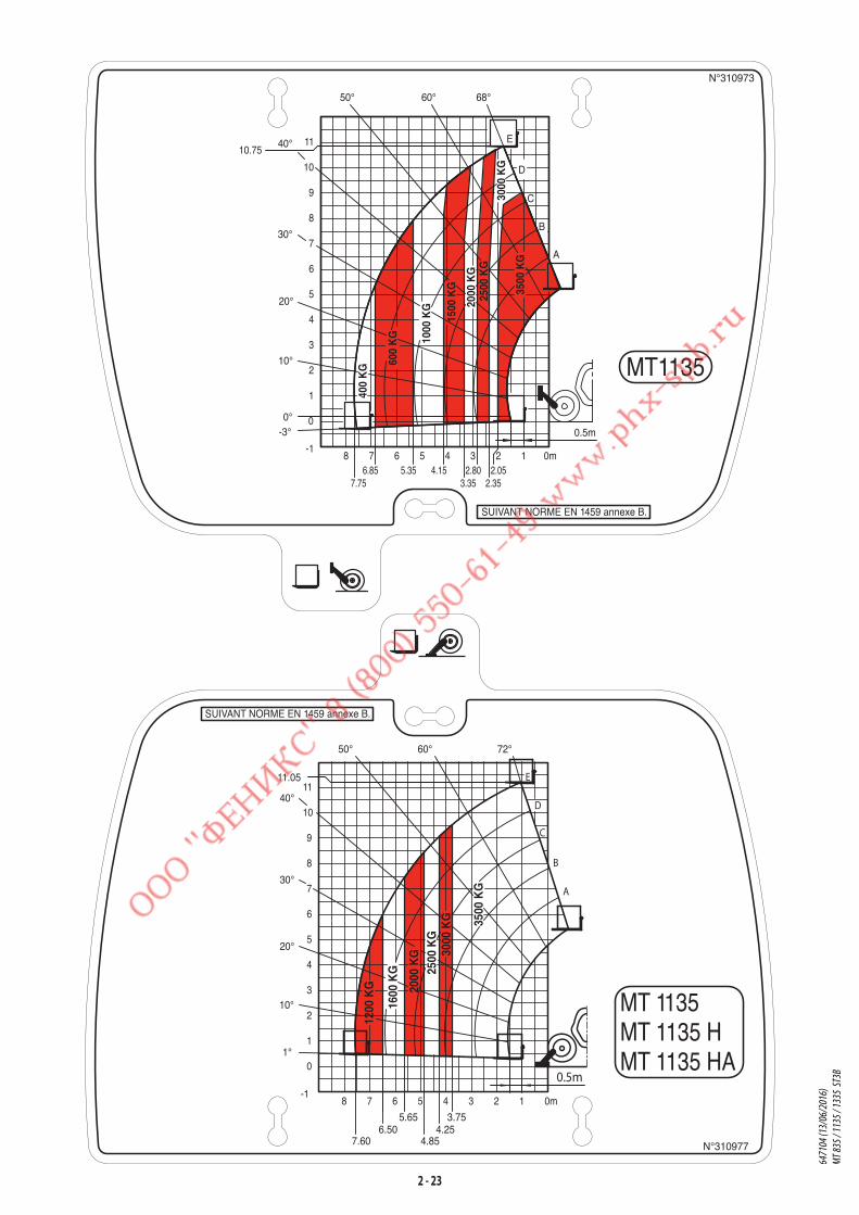
2 - 23
N°310977
SUIVANT NORME EN 1459 annexe B.
0
10
8 7 6 5 4 3
1
2
3
4
5
6
7
8
9
-1
11
2 1 0m
3500
KG
3000
KG
2500
KG
2000
KG
1600
KG
1200
KG
D
C
B
A
E
0.5m
7.606.50
5.65
4.854.25
3.75
50°
1°
10°
20°
30°
40°
60° 72°
11.05
MT 1135MT 1135 HMT 1135 HA
N°310973
SUIVANT NORME EN 1459 annexe B.
MT1135
68°60°50°
40°
30°
20°
10°
0°-3°
10.75
10
8 7 6 5 4 3 2
0
1
2
3
4
5
6
7
8
9
0m1-1
11
2.052.35
2.803.35
4.155.356.857.75
0.5m
E
D
C
B
A
400
KG 60
0 K
G 1000
KG
1500
KG
2000
KG
3000
KG
2500
KG
3500
KG
6471
04 (1
3/06
/201
6)
MT 83
5 / 11
35 / 1
335
ST3B

2 - 24
DIMENSIONS AND LOAD CHART MT 1335 ST3B
A mm 1200B mm 2880C mm 1798C1 mm 1801D mm 5856D1 mm 5859D2 mm 4516E mm 7056F mm 1870F1 mm 1870G mm 445G1 mm 415G2 mm 445G3 mm 135H ° 10H1 ° 10I mm 1178J mm 884K mm 1040L mm 45N mm 1740 - 1803O mm 125P2 ° 38P3 ° 31R mm 3643S mm 8097T mm 4084U1 mm 2419U2 mm 2559V mm 5224V1 mm 1140V2 mm 3850W mm 2284W1 mm 2214W2 mm 1267W3 mm 2214Y ° 12Z ° 114
6471
04 (1
3/06
/201
6)
MT 83
5 / 11
35 / 1
335
ST3B
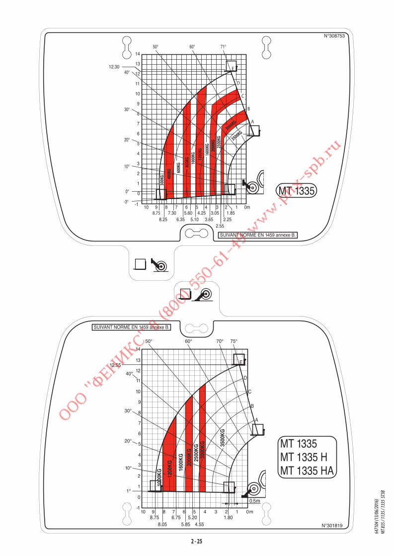
2 - 25
N°308753
MT 1335
SUIVANT NORME EN 1459 annexe B.
50°
20°
10°
0°
30°
40°
-3°
60° 71°
410
13
9
0
1
2
3
4
5
6
7
8
9
10
11
12
14
0m1235678-1
12.30
7.30
2.55
3.05 1.852.253.65
4.255.10
5.606.358.25
8.75
3000KG
300K
G 400K
G 600K
G 1000
KG12
00KG
1600
KG20
00KG
2500
KG
800K
G
3500KG
E
D
C
B
A
MT 1335MT 1335 HMT 1335 HA
N°301819
SUIVANT NORME EN 1459 annexe B.
4.555.858.051.805.206.758.75
3000
KG 35
00K
G
2000
KG
2500
KG
1200
KG
1600
KG
1000
KG
E
D
C
B
A
13
14
12
11
10
9
8
7
6
5
4
3
2
1
0
-1
50° 60° 70° 75°
12.55
8 7 6 5 4 3 2 1 0m910
0.5m
40°
30°
20°
10°
1°
6471
04 (1
3/06
/201
6)
MT 83
5 / 11
35 / 1
335
ST3B

2 - 26
VISIBILITY MT 835 ST3B
Our lift trucks conform to European standard EN15830 with regard to operator visibility.
- Follow the instructions for optimizing operator visibility of the immediate vicinity (see: 1 - OPERATING
AND SAFETY INSTRUCTIONS: INSTRUCTIONS TO THE OPERATOR: DRIVING INSTRUCTIONS UNLADEN AND LADEN: D
- VISIBILITY).
DESCRIPTION AND ADJUSTMENT OF REAR-VIEW MIRRORS
1 - LEFT REAR-VIEW MIRROR
2 - MAIN RIGHT REAR-VIEW MIRROR
3 - CENTRAL RIGHT REAR-VIEW MIRROR
4 - UPPER RIGHT REAR-VIEW MIRROR
5 - REAR REAR-VIEW MIRROR
- Place the lift truck on level ground with the I.C. engine stopped,
and the jib retracted and lowered as far as possible.
- Note the position of the reference points in the
illustrations, to see and correctly adjust the rear-view mirrors.
12
34
5
12
5
4
3
1
5
4
3
2
6471
04 (1
3/06
/201
6)
MT 83
5 / 11
35 / 1
335
ST3B
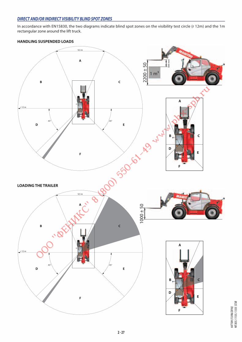
2 - 27
LOADING THE TRAILER
HANDLING SUSPENDED LOADS
r 12 m
9,5 m
45° 45°
A
F
ED
B C
2200
± 5
0
600
mm
1 m3
1000
± 5
0
r 12 m
9,5 m
45° 45°
A
F
ED
B C
DIRECT AND/OR INDIRECT VISIBILITY BLIND SPOT ZONES
In accordance with EN15830, the two diagrams indicate blind spot zones on the visibility test circle (r 12m) and the 1m
rectangular zone around the lift truck.
B
D
A
C
E
F
B
D
A
C
E
F
6471
04 (1
3/06
/201
6)
MT 83
5 / 11
35 / 1
335
ST3B

2 - 28
VISIBILITY MT 1135 ST3B
Our lift trucks conform to European standard EN15830 with regard to operator visibility.
- Follow the instructions for optimizing operator visibility of the immediate vicinity (see: 1 - OPERATING
AND SAFETY INSTRUCTIONS: INSTRUCTIONS TO THE OPERATOR: DRIVING INSTRUCTIONS UNLADEN AND LADEN: D
- VISIBILITY).
DESCRIPTION AND ADJUSTMENT OF REAR-VIEW MIRRORS
1 - LEFT REAR-VIEW MIRROR
2 - MAIN RIGHT REAR-VIEW MIRROR
3 - CENTRAL RIGHT REAR-VIEW MIRROR
4 - UPPER RIGHT REAR-VIEW MIRROR
5 - REAR REAR-VIEW MIRROR
- Place the lift truck on level ground with the I.C. engine stopped,
and the jib retracted and lowered as far as possible.
- Note the position of the reference points in the
illustrations, to see and correctly adjust the rear-view mirrors.
12
34
5
1
2
5
4
3
1
5
3
2
4
6471
04 (1
3/06
/201
6)
MT 83
5 / 11
35 / 1
335
ST3B

2 - 29
LOADING THE TRAILER
HANDLING SUSPENDED LOADS
r 12 m
9,5 m
45° 45°
A
F
ED
B C
2200
± 5
0
600
mm
1 m3
1000
± 5
0
r 12 m
9,5 m
45° 45°
A
F
ED
B C
DIRECT AND/OR INDIRECT VISIBILITY BLIND SPOT ZONES
In accordance with EN15830, the two diagrams indicate blind spot zones on the visibility test circle (r 12m) and the 1m
rectangular zone around the lift truck.
B
D
A
C
E
F
B
D
A
C
E
F
6471
04 (1
3/06
/201
6)
MT 83
5 / 11
35 / 1
335
ST3B
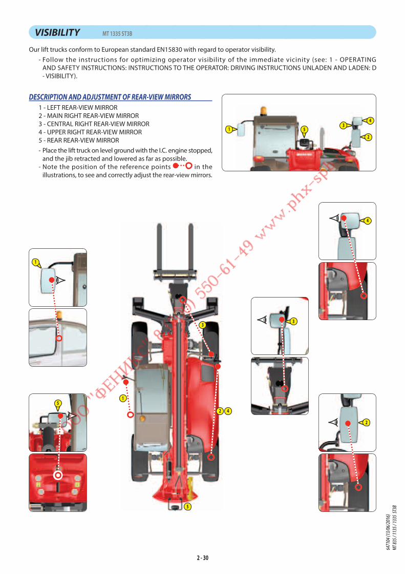
2 - 30
VISIBILITY MT 1335 ST3B
Our lift trucks conform to European standard EN15830 with regard to operator visibility.
- Follow the instructions for optimizing operator visibility of the immediate vicinity (see: 1 - OPERATING
AND SAFETY INSTRUCTIONS: INSTRUCTIONS TO THE OPERATOR: DRIVING INSTRUCTIONS UNLADEN AND LADEN: D
- VISIBILITY).
DESCRIPTION AND ADJUSTMENT OF REAR-VIEW MIRRORS
1 - LEFT REAR-VIEW MIRROR
2 - MAIN RIGHT REAR-VIEW MIRROR
3 - CENTRAL RIGHT REAR-VIEW MIRROR
4 - UPPER RIGHT REAR-VIEW MIRROR
5 - REAR REAR-VIEW MIRROR
- Place the lift truck on level ground with the I.C. engine stopped,
and the jib retracted and lowered as far as possible.
- Note the position of the reference points in the
illustrations, to see and correctly adjust the rear-view mirrors.
1
2
5
4
3
1
5
3
12
34
5
2
4
6471
04 (1
3/06
/201
6)
MT 83
5 / 11
35 / 1
335
ST3B
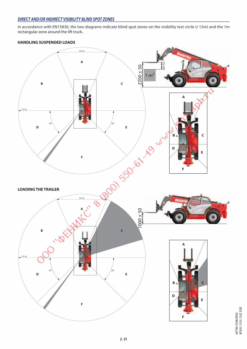
2 - 31
HANDLING SUSPENDED LOADS
DIRECT AND/OR INDIRECT VISIBILITY BLIND SPOT ZONES
In accordance with EN15830, the two diagrams indicate blind spot zones on the visibility test circle (r 12m) and the 1m
rectangular zone around the lift truck.
LOADING THE TRAILER
r 12 m
9,5 m
45° 45°
A
F
ED
B C
1000
± 5
0
r 12 m
9,5 m
45° 45°
A
F
ED
B C 2200
± 5
0
600
mm
1 m3
B
D
A
C
E
F
B
D
A
C
E
F
6471
04 (1
3/06
/201
6)
MT 83
5 / 11
35 / 1
335
ST3B

2 - 32
26
26
40
10
35
33
32
15
21
36
20
128
9
11
41 5
1
4
16
6
7
30
14
16
1616
19
1718
20
36
24
23
24
2
2522
2525
24
27
28 34
29
13
24
3
MT 1135 ST3B / MT 1335 ST3B
4
16
19
20
MT 835 ST3B
8 31
INSTRUMENTS AND CONTROLS
6471
04 (1
3/06
/201
6)
MT 83
5 / 11
35 / 1
335
ST3B
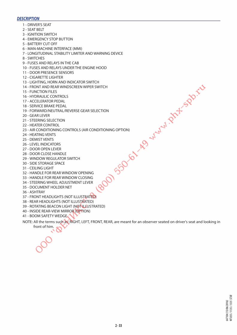
2 - 33
DESCRIPTION
1 - DRIVER'S SEAT
2 - SEAT BELT
3 - IGNITION SWITCH
4 - EMERGENCY STOP BUTTON
5 - BATTERY CUT OFF
6 - MAN-MACHINE INTERFACE (MMI)
7 - LONGITUDINAL STABILITY LIMITER AND WARNING DEVICE
8 - SWITCHES
9 - FUSES AND RELAYS IN THE CAB
10 - FUSES AND RELAYS UNDER THE ENGINE HOOD
11 - DOOR PRESENCE SENSORS
12 - CIGARETTE LIGHTER
13 - LIGHTING, HORN AND INDICATOR SWITCH
14 - FRONT AND REAR WINDSCREEN WIPER SWITCH
15 - FUNCTION FILES
16 - HYDRAULIC CONTROLS
17 - ACCELERATOR PEDAL
18 - SERVICE BRAKE PEDAL
19 - FORWARD/NEUTRAL/REVERSE GEAR SELECTION
20 - GEAR LEVER
21 - STEERING SELECTION
22 - HEATER CONTROL
23 - AIR CONDITIONING CONTROLS (AIR CONDITIONING OPTION)
24 - HEATING VENTS
25 - DEMIST VENTS
26 - LEVEL INDICATORS
27 - DOOR OPEN LEVER
28 - DOOR CLOSE HANDLE
29 - WINDOW REGULATOR SWITCH
30 - SIDE STORAGE SPACE
31 - CEILING LIGHT
32 - HANDLE FOR REAR WINDOW OPENING
33 - HANDLE FOR REAR WINDOW CLOSING
34 - STEERING WHEEL ADJUSTMENT LEVER
35 - DOCUMENT HOLDER NET
36 - ASHTRAY
37 - FRONT HEADLIGHTS (NOT ILLUSTRATED)
38 - REAR HEADLIGHTS (NOT ILLUSTRATED)
39 - ROTATING BEACON LIGHT (NOT ILLUSTRATED)
40 - INSIDE REAR-VIEW MIRROR (OPTION)
41 - BOOM SAFETY WEDGE
NOTE: All the terms such as: RIGHT, LEFT, FRONT, REAR, are meant for an observer seated on driver's seat and looking in
front of him.64
7104
(13/
06/2
016)
MT
835 /
1135
/ 133
5 ST
3B

2 - 34
1 - DRIVER'S SEAT
DRIVER’S SEAT (STANDARD)
DESIGNED FOR MAXIMUM COMFORT, THIS SEAT CAN BE ADJUSTED AS FOLLOWS.
LONGITUDINAL ADJUSTMENT - Unlock the locking lever 1.
- Slide the seat to the desired position.
- Release the lever and be sure it returns to the lock position.
SEAT SUSPENSION ADJUSTMENT - Refer to the seat's graduation.
- Turn knob 2 according to the driver's weight.
ANGLE ADJUSTMENT OF THE BACK-REST - Pull the locking lever 3 upwards.
- Tilt the back-rest to the required position.
- Release the lever and be sure it returns to the locking position.
1
2
4
3
2
3
1
DRIVER'S SEAT (OPTION)
DESIGNED FOR MAXIMUM COMFORT, THIS SEAT CAN BE ADJUSTED AS FOLLOWS.
LONGITUDINAL ADJUSTMENT - Pull the locking lever 1 upwards.
- Slide the seat to the desired position.
- Release the lever and be sure it returns to the lock position.
SEAT CUSHION ADJUSTMENTThe front and the back of the seat cushion can be adjusted separately.
- To adjust the front, push the lever 2 downwards.
- Release it into one of the five possible positions.
- Same procedure to adjust the back by pulling the lever 2 upwards.
SEAT SUSPENSION ADJUSTMENT - Turn the button 3 and adjust according to your weight.
ANGLE ADJUSTMENT OF THE BACK-REST - Lean the back against the back-rest.
- Pull the lever 4 and place the back-rest into one of the possible positions.
DRIVER'S SEAT (OPTION)
DESIGNED FOR MAXIMUM COMFORT, THIS SEAT CAN BE ADJUSTED AS FOLLOWS.
WEIGHT ADJUSTMENT (FIG. A)It is advised that the weight be adjusted when the driver is not sitting in the cab.
- Refer to graduation 1 of the seat.
- Turn knob 2 according to the driver's weight.
NOTE: To avoid any health problems, it is recommended that the weight should be
checked and adjusted before starting up the lift truck.
SEAT HEIGHT ADJUSTMENT (FIG. B) - Raise the seat to the desired position, until you hear the ratchet click. If you raise
the seat above the last notch (stop), the seat returns to the lowest position.
B
A
2 1
6471
04 (1
3/06
/201
6)
MT 83
5 / 11
35 / 1
335
ST3B
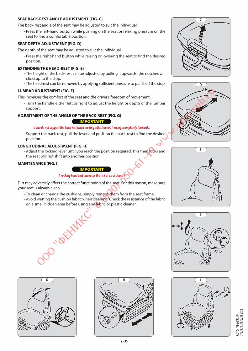
2 - 35
SEAT BACK-REST ANGLE ADJUSTMENT (FIG. C)The back-rest angle of the seat may be adjusted to suit the individual.
- Press the left-hand button while pushing on the seat or relaxing pressure on the
seat to find a comfortable position.
SEAT DEPTH ADJUSTMENT (FIG. D)The depth of the seat may be adjusted to suit the individual.
- Press the right-hand button while raising or lowering the seat to find the desired
position.
EXTENDING THE HEAD-REST (FIG. E) - The height of the back-rest can be adjusted by pulling it upwards (the notches will
click) up to the stop.
- The head-rest can be removed by applying sufficient pressure to pull it off the stop.
LUMBAR ADJUSTMENT (FIG. F)This increases the comfort of the seat and the driver’s freedom of movement.
- Turn the handle either left or right to adjust the height or depth of the lumbar
support.
ADJUSTMENT OF THE ANGLE OF THE BACK-REST (FIG. G) IMPORTANT
If you do not support the back-rest when making adjustments, it swings completely forwards.
- Support the back-rest, pull the lever and position the back-rest to find the desired
position.
LONGITUDINAL ADJUSTMENT (FIG. H) - Adjust the locking lever until you reach the position required. This then locks and
the seat will not shift into another position.
MAINTENANCE (FIG. I) IMPORTANT
A rocking head-rest increases the risk of an accident !
Dirt may adversely affect the correct functioning of the seat. For this reason, make sure
your seat is always clean.
- To clean or change the cushions, simply remove them from the seat frame.
- Avoid wetting the cushion fabric when cleaning. Check the resistance of the fabric
on a small hidden area before using any fabric or plastic cleaner.
D
E
F
IHG
C
6471
04 (1
3/06
/201
6)
MT 83
5 / 11
35 / 1
335
ST3B

2 - 36
PNEUMATIC DRIVER'S SEAT (OPTION)
DESIGNED FOR MAXIMUM COMFORT, THIS SEAT CAN BE ADJUSTED AS FOLLOWS.
WEIGHT AND SEAT HEIGHT ADJUSTMENTWEIGHT ADJUSTMENT (FIG. A)
It is advised that you adjust the seat according to your weight when sitting.
- Switch on lift truck ignition.
- Push or pull lever 1 until green appears in display 2 indicating correct adjustment
according to your weight.
NOTE: To avoid any health problems, it is recommended that the weight should be
checked and adjusted before starting up the lift truck.
SEAT HEIGHT ADJUSTMENT (FIG. B)
IMPORTANT
To avoid causing any damage, do not activate the compressor for over 1 minute.
When weight adjustment has been carried out, you can then modify seat height.
- Keep the ignition on in the lift truck.
- Push or pull lever 1 until green appears and adjust the height of the seat while
checking that the green in display 2 remains visible.
SEAT BACK-REST ANGLE ADJUSTMENT (FIG. C)The back-rest angle of the seat may be adjusted to suit the individual.
- Press the left-hand button while pushing on the seat or relaxing pressure on the
seat to find a comfortable position.
SEAT DEPTH ADJUSTMENT (FIG. D)The depth of the seat may be adjusted to suit the individual.
- Press the right-hand button while raising or lowering the seat to find the desired
position.
EXTENDING THE HEAD-REST (FIG. E) - The height of the back-rest can be adjusted by pulling it upwards (the notches will
click) up to the stop.
- The head-rest can be removed by applying sufficient pressure to pull it off the stop.
LUMBAR ADJUSTMENT (FIG. F)This increases the comfort of the seat and the driver’s freedom of movement.
- Turn the handle either left or right to adjust the height or depth of the lumbar
support.
ADJUSTMENT OF THE ANGLE OF THE BACK-REST (FIG. G) IMPORTANT
If you do not support the back-rest when making adjustments, it swings completely forwards.
- Support the back-rest, pull the lever and position the back-rest to find the desired
position.
A
C
D
GFE
B
6471
04 (1
3/06
/201
6)
MT 83
5 / 11
35 / 1
335
ST3B
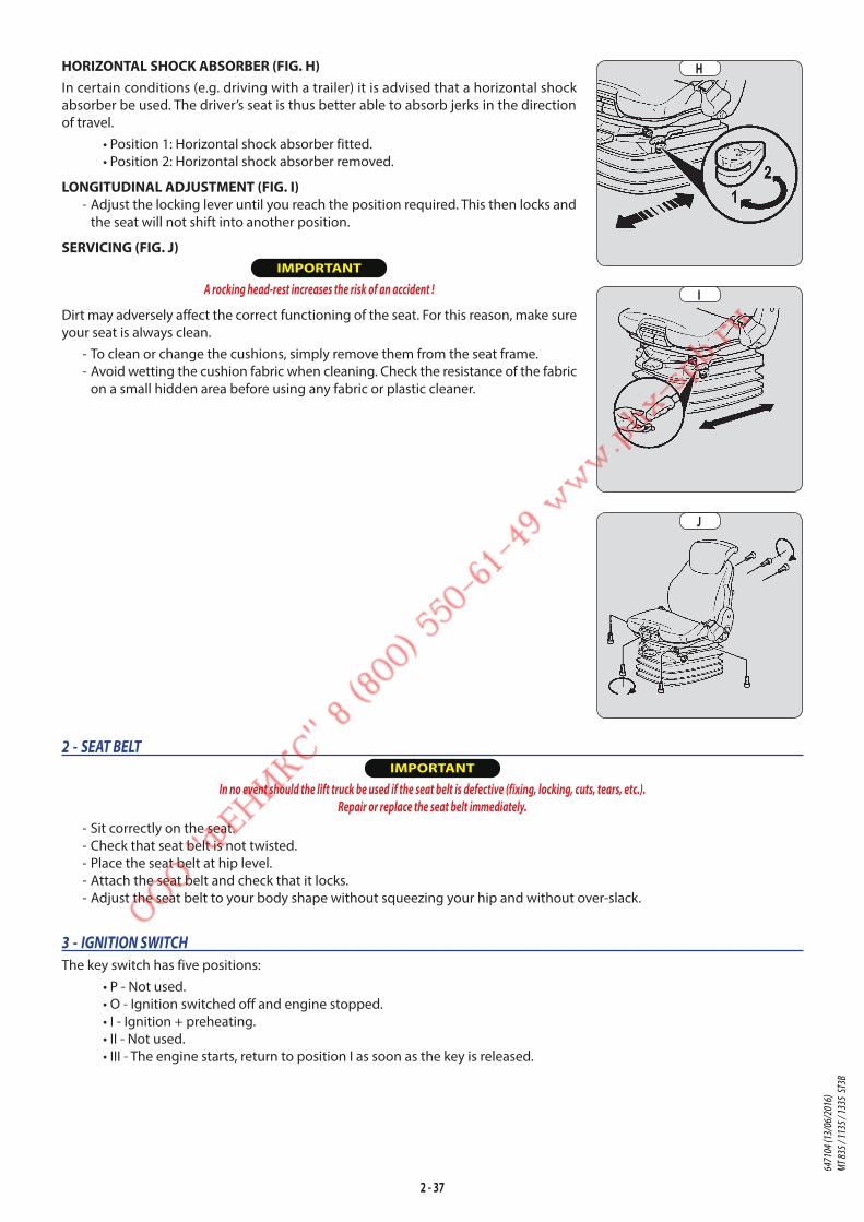
2 - 37
HORIZONTAL SHOCK ABSORBER (FIG. H)In certain conditions (e.g. driving with a trailer) it is advised that a horizontal shock
absorber be used. The driver’s seat is thus better able to absorb jerks in the direction
of travel.
• Position 1: Horizontal shock absorber fitted.
• Position 2: Horizontal shock absorber removed.
LONGITUDINAL ADJUSTMENT (FIG. I) - Adjust the locking lever until you reach the position required. This then locks and
the seat will not shift into another position.
SERVICING (FIG. J) IMPORTANT
A rocking head-rest increases the risk of an accident !
Dirt may adversely affect the correct functioning of the seat. For this reason, make sure
your seat is always clean.
- To clean or change the cushions, simply remove them from the seat frame.
- Avoid wetting the cushion fabric when cleaning. Check the resistance of the fabric
on a small hidden area before using any fabric or plastic cleaner.
I
J
H
2 - SEAT BELT IMPORTANT
In no event should the lift truck be used if the seat belt is defective (fixing, locking, cuts, tears, etc.).
Repair or replace the seat belt immediately.
- Sit correctly on the seat.
- Check that seat belt is not twisted.
- Place the seat belt at hip level.
- Attach the seat belt and check that it locks.
- Adjust the seat belt to your body shape without squeezing your hip and without over-slack.
3 - IGNITION SWITCH
The key switch has five positions:
• P - Not used.
• O - Ignition switched off and engine stopped.
• I - Ignition + preheating.
• II - Not used.
• III - The engine starts, return to position I as soon as the key is released.
6471
04 (1
3/06
/201
6)
MT 83
5 / 11
35 / 1
335
ST3B
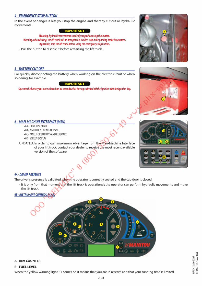
2 - 38
6A - DRIVER PRESENCE
The driver's presence is validated when the operator is correctly seated and the cab door is closed.
- It is only from that moment that the lift truck is operational; the operator can perform hydraulic movements and move
the lift truck.
6B - INSTRUMENT CONTROL PANEL
ABB1
C
D
E E
F
G
HH1
A - REV COUNTER
B - FUEL LEVELWhen the yellow warning light B1 comes on it means that you are in reserve and that your running time is limited.
6 - MAN-MACHINE INTERFACE (MMI)• 6A - DRIVER PRESENCE
• 6B - INSTRUMENT CONTROL PANEL
• 6C - PANEL FOR BUTTONS AND KEYBOARD
• 6D - SCREEN DISPLAY
UPDATED: In order to gain maximum advantage from the Man-Machine Interface
of your lift truck, contact your dealer to receive the most recent available
version of the software.
6A 6D
6B
6C
5 - BATTERY CUT OFF
For quickly disconnecting the battery when working on the electric circuit or when
soldering, for example.
IMPORTANT
Operate the battery cut-out no less than 30 seconds after having switched off the ignition with the ignition key.
4 - EMERGENCY STOP BUTTON
In the event of danger, it lets you stop the engine and thereby cut out all hydraulic
movements.
IMPORTANT
Warning, hydraulic movements suddenly stop when using this button.
Warning, when driving, the lift truck will be brought to a sudden stop if the parking brake is actuated.
If possible, stop the lift truck before using the emergency stop button.
- Pull the button to disable it before restarting the lift truck.
4
5
6471
04 (1
3/06
/201
6)
MT 83
5 / 11
35 / 1
335
ST3B
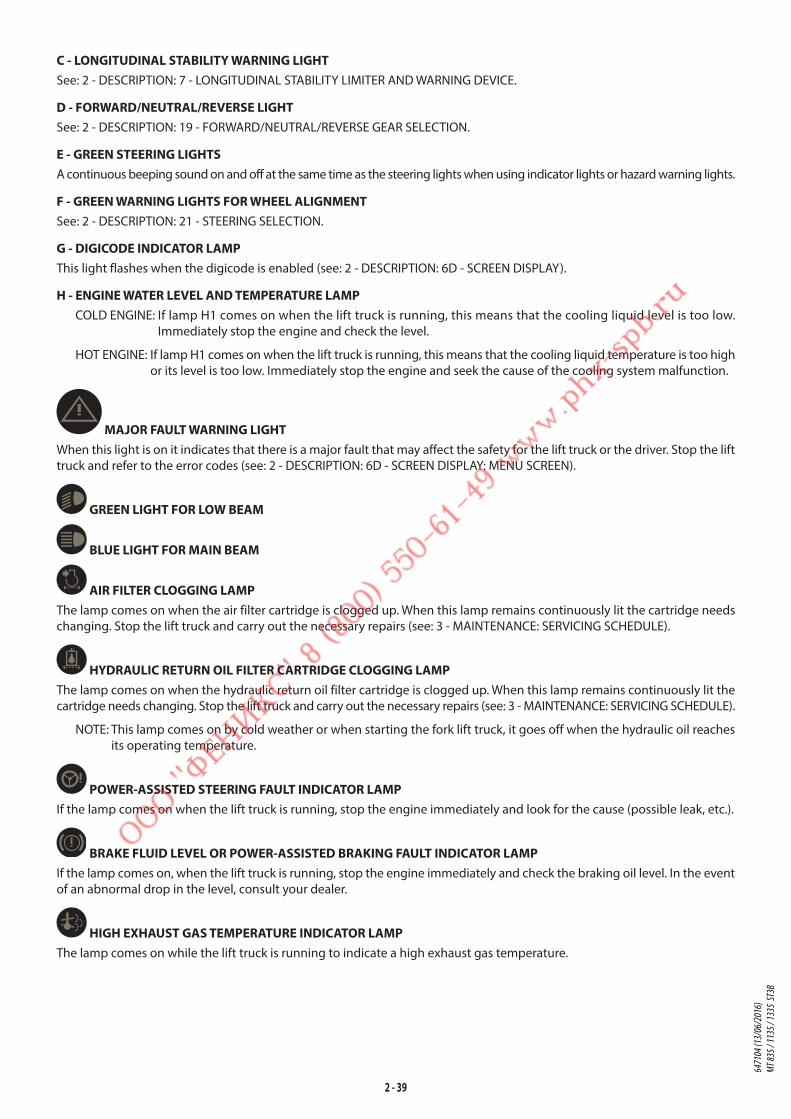
2 - 39
C - LONGITUDINAL STABILITY WARNING LIGHTSee: 2 - DESCRIPTION: 7 - LONGITUDINAL STABILITY LIMITER AND WARNING DEVICE.
D - FORWARD/NEUTRAL/REVERSE LIGHTSee: 2 - DESCRIPTION: 19 - FORWARD/NEUTRAL/REVERSE GEAR SELECTION.
E - GREEN STEERING LIGHTSA continuous beeping sound on and off at the same time as the steering lights when using indicator lights or hazard warning lights.
F - GREEN WARNING LIGHTS FOR WHEEL ALIGNMENTSee: 2 - DESCRIPTION: 21 - STEERING SELECTION.
G - DIGICODE INDICATOR LAMPThis light flashes when the digicode is enabled (see: 2 - DESCRIPTION: 6D - SCREEN DISPLAY).
H - ENGINE WATER LEVEL AND TEMPERATURE LAMPCOLD ENGINE: If lamp H1 comes on when the lift truck is running, this means that the cooling liquid level is too low.
Immediately stop the engine and check the level.
HOT ENGINE: If lamp H1 comes on when the lift truck is running, this means that the cooling liquid temperature is too high
or its level is too low. Immediately stop the engine and seek the cause of the cooling system malfunction.
MAJOR FAULT WARNING LIGHTWhen this light is on it indicates that there is a major fault that may affect the safety for the lift truck or the driver. Stop the lift
truck and refer to the error codes (see: 2 - DESCRIPTION: 6D - SCREEN DISPLAY: MENU SCREEN).
GREEN LIGHT FOR LOW BEAM
BLUE LIGHT FOR MAIN BEAM
AIR FILTER CLOGGING LAMPThe lamp comes on when the air filter cartridge is clogged up. When this lamp remains continuously lit the cartridge needs
changing. Stop the lift truck and carry out the necessary repairs (see: 3 - MAINTENANCE: SERVICING SCHEDULE).
HYDRAULIC RETURN OIL FILTER CARTRIDGE CLOGGING LAMPThe lamp comes on when the hydraulic return oil filter cartridge is clogged up. When this lamp remains continuously lit the
cartridge needs changing. Stop the lift truck and carry out the necessary repairs (see: 3 - MAINTENANCE: SERVICING SCHEDULE).
NOTE: This lamp comes on by cold weather or when starting the fork lift truck, it goes off when the hydraulic oil reaches
its operating temperature.
POWER-ASSISTED STEERING FAULT INDICATOR LAMPIf the lamp comes on when the lift truck is running, stop the engine immediately and look for the cause (possible leak, etc.).
BRAKE FLUID LEVEL OR POWER-ASSISTED BRAKING FAULT INDICATOR LAMPIf the lamp comes on, when the lift truck is running, stop the engine immediately and check the braking oil level. In the event
of an abnormal drop in the level, consult your dealer.
HIGH EXHAUST GAS TEMPERATURE INDICATOR LAMPThe lamp comes on while the lift truck is running to indicate a high exhaust gas temperature.
6471
04 (1
3/06
/201
6)
MT 83
5 / 11
35 / 1
335
ST3B

2 - 40
WATER IN FUEL PRE-FILTER LAMPThis lamp will come on when there is water in the fuel pre-filter. Stop the lift truck and carry out the necessary repairs
(see: 3 - MAINTENANCE: SERVICING SCHEDULE).
ENGINE AUTOMATIC PREHEATING LAMPThis lamp comes on when the lift truck's ignition is switched on and should go out as soon as pre-heating is ended. If it comes
on while the lift truck is in operation, immediately stop the engine and find the cause.
ENGINE OIL PRESSURE LAMPIf the lamp comes on when the lift truck is running, stop the engine immediately and look for the cause (see oil level in engine
crankcase).
NOTE: After starting the engine, the indicator lamp remains on for a few seconds then goes out when the correct engine
oil pressure is reached. The full engine power is then available.
ENGINE FAULT INDICATOR LAMPIf the lamp comes on when the lift truck is running, stop the engine immediately and look for the cause (possible leak, etc.).
NOTE: This lamp comes on the moment the ignition key is in position I and until the engine is started.
BATTERY LOAD LAMPIf this lamp comes on when the lift truck is running, switch off the engine immediately and check the electric circuit and the
alternator belt.
GREEN PROGRESSIVE INCHING TRANSMISSION MODE INDICATOR LAMP (OPTION)This lamp comes on when using the progressive transmission “INCHING” mode (see: 2 - DESCRIPTION: 6C - PANEL FOR BUTTONS
AND KEYBOARD).
GEAR BOX OIL PRESSURE LAMPThis lamp comes on when there is an abnormal drop in gear box pressure. Stop the lift truck and look for the cause (e.g., Low oil
level in the transmission, internal leak in the transmission, etc.).
GEAR BOX OIL TEMPERATURE LAMPThis lamp comes on when the temperature of the gear box oil is abnormally high. In this case, place the forward/reverse
selector in neutral and let the engine running at idle for a few minutes. If the lamp remains on, stop the lift truck and contact
your dealer.
NOTE: Abnormal heating of the oil may be linked to an incorrect use of the gear box ratios (see: 2 - DESCRIPTION: 20 -
GEAR LEVER).
PARKING BRAKE LAMPThis lamp comes on when the parking brake is applied.
A flashing lamp indicates a fault (see: 2 - DESCRIPTION: 6D - SCREEN DISPLAY: MENU SCREEN).
HYDRAULIC MOVEMENT NEUTRALISATION LAMPThe lamp lights when the hydraulic controls are neutralised and when a forbidden hydraulic movement is requested.
NOTE: When driving on the road, it is highly recommended that you lock all the hydraulic movements
6471
04 (1
3/06
/201
6)
MT 83
5 / 11
35 / 1
335
ST3B

2 - 41
6C - PANEL FOR BUTTONS AND KEYBOARD
A beep is sounded each time one of the buttons is pressed.
“BUCKET“ MODEOnly for MT 835 ST3B / MT 1135 ST3B
See: 2 - DESCRIPTION: 7 - LONGITUDINAL STABILITY LIMITER AND WARNING DEVICE.
OPTION PROGRESSIVE TRANSMISSION “INCHING” MODE
STANDARD TRANSMISSION MODE (default mode)
OPTION PROGRESSIVE TRANSMISSION “INCHING” MODE IN FORWARD AND REVERSE GEAR (OPTION)
• The indicator on the instrument control panel will light when it is in use.
The operating screen displays the enabled mode. Press the button to display the other available mode(s).
CHANGE MODE
ON TYRES
Press 1
Confirm
Cancel
ON TYRES
Press 1
Confirm
Cancel
“SUSPENDED LOAD“ MODESee: 2 - DESCRIPTION: 7 - LONGITUDINAL STABILITY LIMITER AND WARNING DEVICE.
6471
04 (1
3/06
/201
6)
MT 83
5 / 11
35 / 1
335
ST3B
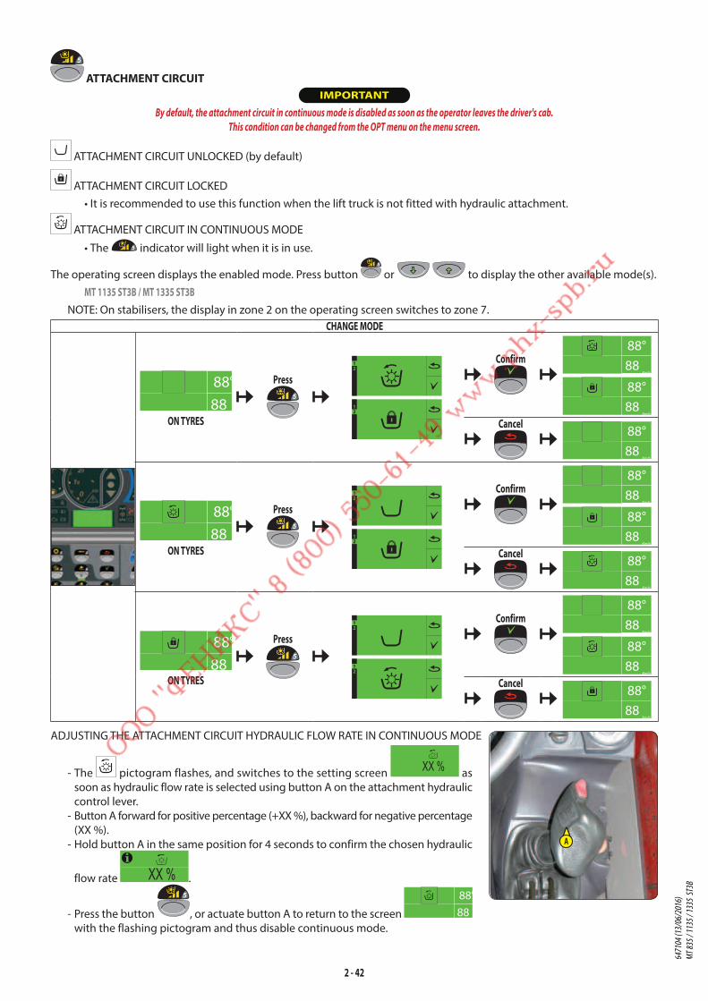
2 - 42
ATTACHMENT CIRCUIT IMPORTANT
By default, the attachment circuit in continuous mode is disabled as soon as the operator leaves the driver's cab.
This condition can be changed from the OPT menu on the menu screen.
ATTACHMENT CIRCUIT UNLOCKED (by default)
ATTACHMENT CIRCUIT LOCKED
• It is recommended to use this function when the lift truck is not fitted with hydraulic attachment.
ATTACHMENT CIRCUIT IN CONTINUOUS MODE
• The indicator will light when it is in use.
The operating screen displays the enabled mode. Press button or to display the other available mode(s).
MT 1135 ST3B / MT 1335 ST3BNOTE: On stabilisers, the display in zone 2 on the operating screen switches to zone 7.
CHANGE MODE
ON TYRES
Press12
12
Confirm
Cancel
ON TYRES
Press12
12
Confirm
Cancel
ON TYRES
Press12
12
Confirm
Cancel
ADJUSTING THE ATTACHMENT CIRCUIT HYDRAULIC FLOW RATE IN CONTINUOUS MODE
- The pictogram flashes, and switches to the setting screen as
soon as hydraulic flow rate is selected using button A on the attachment hydraulic
control lever.
- Button A forward for positive percentage (+XX %), backward for negative percentage
(XX %).
- Hold button A in the same position for 4 seconds to confirm the chosen hydraulic
flow rate .
- Press the button , or actuate button A to return to the screen
with the flashing pictogram and thus disable continuous mode.
A
6471
04 (1
3/06
/201
6)
MT 83
5 / 11
35 / 1
335
ST3B
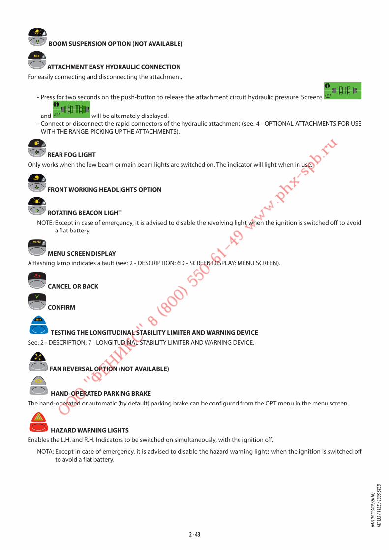
2 - 43
BOOM SUSPENSION OPTION (NOT AVAILABLE)
ATTACHMENT EASY HYDRAULIC CONNECTIONFor easily connecting and disconnecting the attachment.
- Press for two seconds on the push-button to release the attachment circuit hydraulic pressure. Screens
and will be alternately displayed.
- Connect or disconnect the rapid connectors of the hydraulic attachment (see: 4 - OPTIONAL ATTACHMENTS FOR USE
WITH THE RANGE: PICKING UP THE ATTACHMENTS).
REAR FOG LIGHTOnly works when the low beam or main beam lights are switched on. The indicator will light when in use.
FRONT WORKING HEADLIGHTS OPTION
ROTATING BEACON LIGHTNOTE: Except in case of emergency, it is advised to disable the revolving light when the ignition is switched off to avoid
a flat battery.
MENU SCREEN DISPLAYA flashing lamp indicates a fault (see: 2 - DESCRIPTION: 6D - SCREEN DISPLAY: MENU SCREEN).
CANCEL OR BACK
CONFIRM
TESTING THE LONGITUDINAL STABILITY LIMITER AND WARNING DEVICESee: 2 - DESCRIPTION: 7 - LONGITUDINAL STABILITY LIMITER AND WARNING DEVICE.
FAN REVERSAL OPTION (NOT AVAILABLE)
HAND-OPERATED PARKING BRAKEThe hand-operated or automatic (by default) parking brake can be configured from the OPT menu in the menu screen.
HAZARD WARNING LIGHTSEnables the L.H. and R.H. Indicators to be switched on simultaneously, with the ignition off.
NOTA: Except in case of emergency, it is advised to disable the hazard warning lights when the ignition is switched off
to avoid a flat battery.
6471
04 (1
3/06
/201
6)
MT 83
5 / 11
35 / 1
335
ST3B

2 - 44
LOCKING HYDRAULIC CONTROLS
HYDRAULIC CONTROLS AVAILABLE (by default)
TILT CONTROL LOCKED
HYDRAULIC CONTROLS LOCKED
• When driving on the road, it is strongly recommended that you lock all hydraulic movements.
Press button or to display the other available mode(s), the first screen displayed is the opposite of the
enabled mode.
CHANGE MODE
Press 12
12
Confirm
Cancel
Press
12
12
Confirm
Cancel
Press 12
12
Confirm
Cancel
6D - SCREEN DISPLAY
SCREEN OFFLift truck parked, with ignition off and without the driver.
MANITOU LOGO SCREEN
System initialising. A beep is sounded when this screen appears. If the screen remains permanently displayed, contact your
dealer.
DIGIC
0 0 _ _ DIGICODE SCREEN
The digicode is disabled by default. It can be enabled from the OPT menu on the menu screen. A beep is sounded when this
screen appears.
- Switch on the lift truck ignition. Enter the code (default 0000) using the keys on the keyboard and confirm with the
confirm button . Automatically moves to the next character.
NOTE: The code can be changed in the OPT menu in the menu screen.
HOUR METER SCREENWith the operator present in the cab, the ignition switched off, the screen displays the total number of hours worked [888888h],
the number of hours for that working day [888.88h] and the number of hours before the next major maintenance [888h].
6471
04 (1
3/06
/201
6)
MT 83
5 / 11
35 / 1
335
ST3B
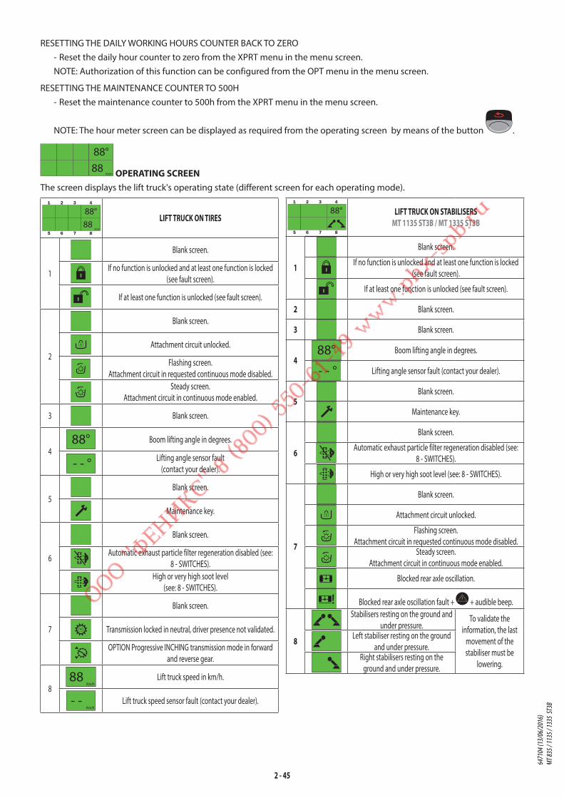
2 - 45
RESETTING THE DAILY WORKING HOURS COUNTER BACK TO ZERO
- Reset the daily hour counter to zero from the XPRT menu in the menu screen.
NOTE: Authorization of this function can be configured from the OPT menu in the menu screen.
RESETTING THE MAINTENANCE COUNTER TO 500H
- Reset the maintenance counter to 500h from the XPRT menu in the menu screen.
NOTE: The hour meter screen can be displayed as required from the operating screen by means of the button .
OPERATING SCREENThe screen displays the lift truck's operating state (different screen for each operating mode).
LIFT TRUCK ON TIRES
1
Blank screen.
If no function is unlocked and at least one function is locked
(see fault screen).
If at least one function is unlocked (see fault screen).
2
Blank screen.
Attachment circuit unlocked.
Flashing screen.
Attachment circuit in requested continuous mode disabled.
Steady screen.
Attachment circuit in continuous mode enabled.
3 Blank screen.
4
Boom lifting angle in degrees.
Lifting angle sensor fault
(contact your dealer).
5
Blank screen.
Maintenance key.
6
Blank screen.
Automatic exhaust particle filter regeneration disabled (see:
8 - SWITCHES).
High or very high soot level
(see: 8 - SWITCHES).
7
Blank screen.
Transmission locked in neutral, driver presence not validated.
OPTION Progressive INCHING transmission mode in forward
and reverse gear.
8
Lift truck speed in km/h.
Lift truck speed sensor fault (contact your dealer).
LIFT TRUCK ON STABILISERS
MT 1135 ST3B / MT 1335 ST3B
1
Blank screen.
If no function is unlocked and at least one function is locked
(see fault screen).
If at least one function is unlocked (see fault screen).
2 Blank screen.
3 Blank screen.
4Boom lifting angle in degrees.
Lifting angle sensor fault (contact your dealer).
5Blank screen.
Maintenance key.
6
Blank screen.
Automatic exhaust particle filter regeneration disabled (see:
8 - SWITCHES).
High or very high soot level (see: 8 - SWITCHES).
7
Blank screen.
Attachment circuit unlocked.
Flashing screen.
Attachment circuit in requested continuous mode disabled.Steady screen.
Attachment circuit in continuous mode enabled.
Blocked rear axle oscillation.
Blocked rear axle oscillation fault + + audible beep.
8
Stabilisers resting on the ground and
under pressure.To validate the
information, the last
movement of the
stabiliser must be
lowering.
Left stabiliser resting on the ground
and under pressure.Right stabilisers resting on the
ground and under pressure.
6471
04 (1
3/06
/201
6)
MT 83
5 / 11
35 / 1
335
ST3B

2 - 46
HELP SCREENOne of these screens appears to inform the operator of the operations to be performed in the current configuration. The
appearance of this screen generates an audible beep.
Maintenance required
(see: 3 - MAINTENANCE: D - EVERY 500 HOURS SERVICE).Time to next maintenance in hours
(see: 3 - MAINTENANCE: D - EVERY 500 HOURS SERVICE).Engine oil maintenance required
(see: 3 - MAINTENANCE: D - EVERY 500 HOURS SERVICE).
Engine oil maintenance OK.
Shut the door.
Speed too high.
Speed too high.
Retract the jib to raise the stabilisers.
MT 1135 ST3B / MT 1335 ST3BSet down the stabilizers.
MT 1135 ST3B / MT 1335 ST3BRetract the stabilizers.
MT 1135 ST3B / MT 1335 ST3B
Lower the jib.
Using the attachment circuit in continuous mode and indicating
the hydraulic capacity.
Reset the forward/reverse selector via neutral.
Defective indicator bulb.
Computer over-heat (consult your dealer).
Computer fault (consult your dealer).
Driver presence not detected
(see: 2 - DESCRIPTION: 6 - MAN-MACHINE INTERFACE (MMI).
Parking brake applied.
Hydraulic attachment decompression in progress.
Hydraulic attachment decompression in progress.
Low fuel level.
Ventilation fault (consult your dealer).
High soot level in exhaust particle filter automatic regeneration
enabled mode (see: 2 - DESCRIPTION: 8 - SWITCHES).High soot level in exhaust particle filter automatic regeneration
disabled mode (see: 2 - DESCRIPTION: 8 - SWITCHES).Moderate soot level in exhaust particle filter automatic
regeneration enabled mode (see: 2 - DESCRIPTION: 8 - SWITCHES).Moderate soot level in exhaust particle filter automatic
regeneration disabled mode (see: 2 - DESCRIPTION: 8 - SWITCHES).
"Stationary lift truck" exhaust particle filter regeneration in
progress (see: 3 - MAINTENANCE: I - OCCASIONAL MAINTENANCE).Condition not met for "stationary lift truck" exhaust particle
filter regeneration (see: 3 - MAINTENANCE: I - OCCASIONAL
MAINTENANCE).Exhaust particle filter automatic regeneration enabled
(see: 2 - DESCRIPTION: 8 - SWITCHES).Exhaust particle filter automatic regeneration disabled
(see: 2 - DESCRIPTION: 8 - SWITCHES).
FAULT SCREEN IMPORTANT
In any event, stop the lift truck and contact your dealer.
By default, the operator is not permitted to unlock the functions (see: 2 - DESCRIPTION: 6D - SCREEN DISPLAY: MENU SCREEN).
One of these screens appears when the system detects an operating defect on the lift truck. A beep is sounded when this
screen appears.
These defects cause certain functions to be prohibited in
order to ensure safety. However it is possible for the operator
and under his own responsibility (and/or that of the person
in charge of the establishment) to override the prohibition in
order to secure the parking of the lift truck (e.g., unlocking the
hydraulic distributor fault in order to retract and lower the jib).
The unlocking is activated temporarily, the function will be
locked again as soon as the engine is switched off.
Jib raising fault.
Hydraulic control fault.
Fuel gauge fault.
Transmission fault.
Steering fault.
Parking brake fault.
6471
04 (1
3/06
/201
6)
MT 83
5 / 11
35 / 1
335
ST3B

2 - 47
MENU SCREEN
- Press the button to display the menu screen with the time and date. Navigate horizontally between menus using
the buttons and vertically in the sub-menus using the buttons .
INFO• Time and date (by default).
• Lift truck in degraded mode and/or fault detected (see error code table).
• “Check Maintenance” appears for a few seconds if maintenance is necessary.
CLOCK• HOUR: Change the hour.
• DATE: Change the date.
• FORM: Change the time or date format.
LCD• BACKL: Backlight.
• CONTR: Contrast.
OPTThe contents of this menu can be accessed by means of a customer password.
• RST H: Resetting of daily hour counter to zero, permitted (by default) or not permitted.
• PARK: Hand-operated parking brake or automatic (by default).
• CFLOW: Forced operation without driver presence permitted (by default) or not permitted.
• LLMC: Disabling of aggravating hydraulic movement cut-off permitted (by default) or not permitted.
• PASS: Fault override permitted (by default) or not permitted.
• UNIT: Speed of travel displayed in MPH or Km/h (by default).
• DIGI1: Digicode enabled (by default) or not enabled.
• DIGI2: Change the 4 figure digicode (lift truck start-up).
• CUST: Change the customer code.
DIAGThe contents of this menu enables your dealer to perform a diagnosis on the Man-Machine Interface.
XPRT• RESET > HOURM: Reset the daily working hours counter to zero.
MAINT: Reset the maintenance interval to 500 hours.
OIL: Reset the engine oil maintenance to 500h (engine stopped).
• ADMIN > ADMIN: Change the administrator code.
• ERASE > MC: Clear faults from the computer of the Man-Machine Interface.
MP1: Clear faults from computer MP1.
MP2: Clear faults from computer MP2.
• CALIB > SECU: Enter the administrator code.
GAUGE: Recalibration of strain gauge.
BOOM: Boom angle calibration.
BRAKE: Brake pedal calibration (Inching mode OPTION).
UNLOCKING THE FUNCTION (if authorised)
- Validate with button to unlock the fault.
Lock/unlock transmission fault.
Lock/unlock stabilizer fault.
MT 1135 ST3B / MT 1335 ST3BLock/unlock roll fault.
MT 1135 ST3B / MT 1335 ST3B
Lock/unlock hydraulic control fault.
Lock/unlock parking brake fault.
6471
04 (1
3/06
/201
6)
MT 83
5 / 11
35 / 1
335
ST3B

2 - 48
7 - LONGITUDINAL STABILITY LIMITER AND WARNING DEVICE
MT 835 ST3BMT 1135 ST3B
IMPORTANT
The operator must respect the lift truck's load chart, and the operating mode according to the attachment.
This device warns the operator of the lift truck's longitudinal stability limits. However, lateral stability can reduce the load
chart in the upper part, and this reduction is not detected by the device.
Depending on the type of work required, the longitudinal stability limiter and warning device allows the operator to operate
the lift truck in complete safety.
STANDARDMODE X kg X
"HANDLING" MODE (use with forks) - By default, the device is in "HANDLING" MODE when the lift truck is started-up, except if "BUCKET" MODE has been
selected before switching off the ignition.
kg
"BUCKET" MODE (use with bucket) - Place the lift truck in the transport position.
- Hold down the button, "BUCKET" MODE is confirmed by an audible beep and the lighting of the indicator lamp.
- Press this button again to return to "HANDLING" MODE.
NOTE: "BUCKET" MODE remains enabled as long as the mode is not changed by the operator, even after switching off
the ignition.
Kg
Kg "SUSPENDED LOAD" MODE (use with hoist) (offering a higher margin of error)
- Place the lift truck in the transport position.
- Hold down the button, the "SUSPENDED LOAD" MODE is confirmed by a beep and the lighting of the indicator
lamp. Hydraulic inclination movements are neutralised, as well as the lifting movement when the longitudinal limit is
reached (indicator lamp A8 lit).
- Press this button again or switch off the ignition with the ignition key to return to "HANDLING" MODE.
A - VISUAL ALARMS• A1 - A2 - A3: There is a significant reserve of longitudinal stability.
• A4 - A5: The lift truck is approaching the limit of longitudinal stability, move
with care.
• A6: The lift truck is close to the limit for longitudinal stability. Drive carefully.
• A7: The lift truck is very close to the limit of longitudinal stability. Maneuver
with extreme caution.
• A8: The lift truck is at the authorised limit of longitudinal stability.
B - HYDRAULIC MOVEMENT CUT-OFFNOTE: Cut-off may be preceded by an automatic slowing of hydraulic movement.
"HANDLING" MODE
• A8: All "AGGRAVATING" hydraulic movements are cut-off. Only perform de-aggravating hydraulic movements in the
following order: retract and raise the boom.
"BUCKET" MODE
• A8: The boom lowering and extension movements are cut-off, the other movements remain available.
"SUSPENDED LOAD" MODE
• A8: All "AGGRAVATING" and boom raising hydraulic movements are cut-off. Only the boom retraction hydraulic
movement is available.
A8
A7
A6
A5
A4
A3
A2
A1
C1
6471
04 (1
3/06
/201
6)
MT 83
5 / 11
35 / 1
335
ST3B
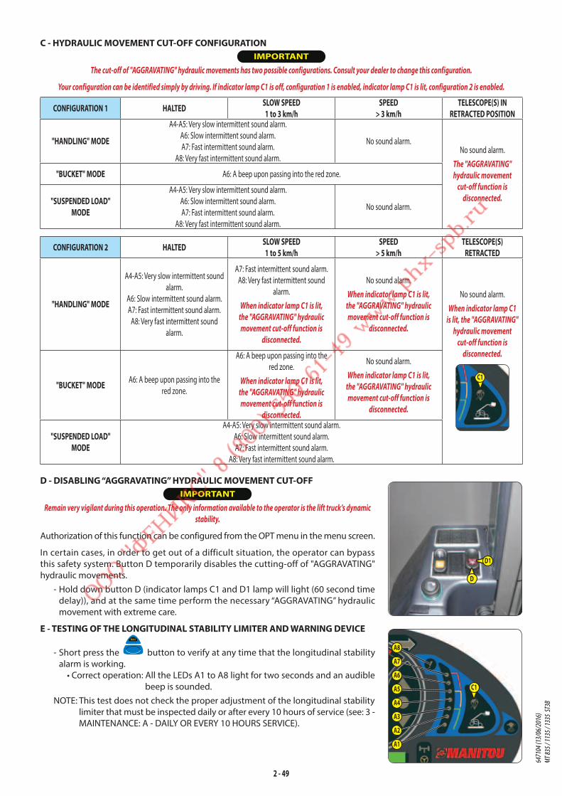
2 - 49
C - HYDRAULIC MOVEMENT CUT-OFF CONFIGURATION IMPORTANT
The cut-off of "AGGRAVATING" hydraulic movements has two possible configurations. Consult your dealer to change this configuration.
Your configuration can be identified simply by driving. If indicator lamp C1 is off, configuration 1 is enabled, indicator lamp C1 is lit, configuration 2 is enabled.
CONFIGURATION 1 HALTED SLOW SPEED1 to 3 km/h
SPEED > 3 km/h
TELESCOPE(S) IN RETRACTED POSITION
"HANDLING" MODE
A4-A5: Very slow intermittent sound alarm.
A6: Slow intermittent sound alarm.
A7: Fast intermittent sound alarm.
A8: Very fast intermittent sound alarm.
No sound alarm.No sound alarm.
The "AGGRAVATING"
hydraulic movement
cut-off function is
disconnected.
"BUCKET" MODE A6: A beep upon passing into the red zone.
"SUSPENDED LOAD" MODE
A4-A5: Very slow intermittent sound alarm.
A6: Slow intermittent sound alarm.
A7: Fast intermittent sound alarm.
A8: Very fast intermittent sound alarm.
No sound alarm.
CONFIGURATION 2 HALTED SLOW SPEED1 to 5 km/h
SPEED > 5 km/h
TELESCOPE(S)RETRACTED
"HANDLING" MODE
A4-A5: Very slow intermittent sound
alarm.
A6: Slow intermittent sound alarm.
A7: Fast intermittent sound alarm.
A8: Very fast intermittent sound
alarm.
A7: Fast intermittent sound alarm.
A8: Very fast intermittent sound
alarm.
When indicator lamp C1 is lit,
the "AGGRAVATING" hydraulic
movement cut-off function is
disconnected.
No sound alarm.
When indicator lamp C1 is lit,
the "AGGRAVATING" hydraulic
movement cut-off function is
disconnected.
No sound alarm.
When indicator lamp C1
is lit, the "AGGRAVATING"
hydraulic movement
cut-off function is
disconnected.
C1"BUCKET" MODE A6: A beep upon passing into the
red zone.
A6: A beep upon passing into the
red zone.
When indicator lamp C1 is lit,
the "AGGRAVATING" hydraulic
movement cut-off function is
disconnected.
No sound alarm.
When indicator lamp C1 is lit,
the "AGGRAVATING" hydraulic
movement cut-off function is
disconnected.
"SUSPENDED LOAD" MODE
A4-A5: Very slow intermittent sound alarm.
A6: Slow intermittent sound alarm.
A7: Fast intermittent sound alarm.
A8: Very fast intermittent sound alarm.
D - DISABLING “AGGRAVATING” HYDRAULIC MOVEMENT CUT-OFF IMPORTANT
Remain very vigilant during this operation. The only information available to the operator is the lift truck’s dynamic
stability.
Authorization of this function can be configured from the OPT menu in the menu screen.
In certain cases, in order to get out of a difficult situation, the operator can bypass
this safety system. Button D temporarily disables the cutting-off of "AGGRAVATING"
hydraulic movements.
- Hold down button D (indicator lamps C1 and D1 lamp will light (60 second time
delay)), and at the same time perform the necessary “AGGRAVATING” hydraulic
movement with extreme care.
E - TESTING OF THE LONGITUDINAL STABILITY LIMITER AND WARNING DEVICE
- Short press the button to verify at any time that the longitudinal stability
alarm is working.
• Correct operation: All the LEDs A1 to A8 light for two seconds and an audible
beep is sounded.
NOTE: This test does not check the proper adjustment of the longitudinal stability
limiter that must be inspected daily or after every 10 hours of service (see: 3 -
MAINTENANCE: A - DAILY OR EVERY 10 HOURS SERVICE).
A8
A7
A6
A5
A4
A3
A2
A1
C1
D
D1
6471
04 (1
3/06
/201
6)
MT 83
5 / 11
35 / 1
335
ST3B
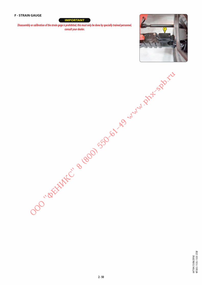
2 - 50
F - STRAIN GAUGE IMPORTANT
Disassembly or calibration of the strain gage is prohibited, this must only be done by specially trained personnel,
consult your dealer. F
6471
04 (1
3/06
/201
6)
MT 83
5 / 11
35 / 1
335
ST3B

2 - 51
8 - LONGITUDINAL STABILITY LIMITER AND WARNING DEVICE
MT 1335 ST3B IMPORTANT
The operator must respect the lift truck's load chart, and the operating mode according to the attachment.
This device warns the operator of the lift truck's longitudinal stability limits. However, lateral stability can reduce the load
chart in the upper part, and this reduction is not detected by the device.
Depending on the type of work required, the longitudinal stability limiter and warning device allows the operator to operate
the lift truck in complete safety.
STANDARDMODE kg X "HANDLING" MODE (use with forks)
By default, the device is in "HANDLING" MODE each time the lift
truck is started.
Kg "SUSPENDED LOAD" MODE (use with hoist) (offering a higher margin of error) Place the lift truck in the transport position.
- Hold down the button, the "SUSPENDED LOAD" MODE is confirmed by a beep and the lighting of the indicator
lamp. Hydraulic inclination movements are neutralised, as well as the lifting movement when the longitudinal limit is
reached (indicator lamp A8 lit).
- Press this button again or switch off the ignition with the ignition key to return to "HANDLING" MODE.
A - VISUAL ALARMS• A1 - A2 - A3: There is a significant reserve of longitudinal stability.
• A4 - A5: The lift truck is approaching the limit of longitudinal stability, move
with care.
• A6: The lift truck is close to the limit for longitudinal stability. Drive carefully.
• A7: The lift truck is very close to the limit of longitudinal stability. Maneuver
with extreme caution.
• A8: The lift truck is at the authorised limit of longitudinal stability.
B - HYDRAULIC MOVEMENT CUT-OFFNOTE: Cut-off may be preceded by an automatic slowing of hydraulic movement.
"HANDLING" MODE
• A8: All “AGGRAVATING” hydraulic movements are cut-off. Only perform de-aggravating hydraulic movements in the
following order: retract and raise the boom.
"SUSPENDED LOAD" MODE
• A8: All “AGGRAVATING” and boom raising hydraulic movements are cut-off. Only the boom retraction hydraulic
movement is available.
A8
A7
A6
A5
A4
A3
A2
A1
C1
6471
04 (1
3/06
/201
6)
MT 83
5 / 11
35 / 1
335
ST3B
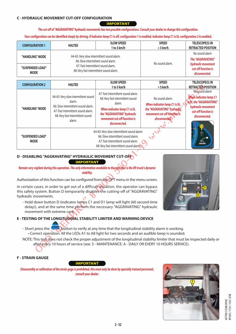
2 - 52
C - HYDRAULIC MOVEMENT CUT-OFF CONFIGURATION IMPORTANT
The cut-off of "AGGRAVATING" hydraulic movements has two possible configurations. Consult your dealer to change this configuration.
Your configuration can be identified simply by driving. If indicator lamp C1 is off, configuration 1 is enabled, indicator lamp C1 is lit, configuration 2 is enabled.
CONFIGURATION 1 HALTED SLOW SPEED1 to 3 km/h
SPEED> 3 km/h
TELESCOPE(S) IN RETRACTED POSITION
"HANDLING" MODE A4-A5: Very slow intermittent sound alarm.
A6: Slow intermittent sound alarm.
A7: Fast intermittent sound alarm.
A8: Very fast intermittent sound alarm.
No sound alarm.
No sound alarm
The "AGGRAVATING"
hydraulic movement
cut-off function is
disconnected.
"SUSPENDED LOAD" MODE
CONFIGURATION 2 HALTED SLOW SPEED 1 to 5 km/h
SPEED> 5 km/h
TELESCOPE(S) IN RETRACTED POSITION
"HANDLING" MODE
A4-A5: Very slow intermittent sound
alarm.
A6: Slow intermittent sound alarm.
A7: Fast intermittent sound alarm.
A8: Very fast intermittent sound
alarm.
A7: Fast intermittent sound alarm.
A8: Very fast intermittent sound
alarm.
When indicator lamp C1 is lit,
the "AGGRAVATING" hydraulic
movement cut-off function is
disconnected.
No sound alarm.
When indicator lamp C1 is lit,
the "AGGRAVATING" hydraulic
movement cut-off function is
disconnected.
No sound alarm
When indicator lamp C1
is lit, the "AGGRAVATING"
hydraulic movement
cut-off function is
disconnected.
C1
"SUSPENDED LOAD" MODE
A4-A5: Very slow intermittent sound alarm.
A6: Slow intermittent sound alarm.
A7: Fast intermittent sound alarm.
A8: Very fast intermittent sound alarm.
D - DISABLING "AGGRAVATING" HYDRAULIC MOVEMENT CUT-OFF IMPORTANT
Remain very vigilant during this operation. The only information available to the operator is the lift truck’s dynamic
stability.
Authorization of this function can be configured from the OPT menu in the menu screen.
In certain cases, in order to get out of a difficult situation, the operator can bypass
this safety system. Button D temporarily disables the cutting-off of "AGGRAVATING"
hydraulic movements.
- Hold down button D (indicator lamps C1 and D1 lamp will light (60 second time
delay)), and at the same time perform the necessary "AGGRAVATING" hydraulic
movement with extreme care.
E - TESTING OF THE LONGITUDINAL STABILITY LIMITER AND WARNING DEVICE
- Short press the button to verify at any time that the longitudinal stability alarm is working.
• Correct operation: All the LEDs A1 to A8 light for two seconds and an audible beep is sounded.
NOTE: This test does not check the proper adjustment of the longitudinal stability limiter that must be inspected daily or
after every 10 hours of service (see: 3 - MAINTENANCE: A - DAILY OR EVERY 10 HOURS SERVICE).
F - STRAIN GAUGE IMPORTANT
Disassembly or calibration of the strain gage is prohibited, this must only be done by specially trained personnel,
consult your dealer.
F
D
D1
6471
04 (1
3/06
/201
6)
MT 83
5 / 11
35 / 1
335
ST3B

2 - 53
9 - SWITCHES
A - REAR WORKING LIGHTS OPTION
B - WORKING LIGHTS ON TELESCOPE OPTION
C - ROOF WINDSCREEN WIPER AND WINDSCREEN WASHERThis switch, when set in the "high" position, allows the windscreen wiper to be worked
and with the "down" position pressed, the windscreen-washer to be operated.
D - SIDE WINDSCREEN WIPER AND WINDSCREEN WASHERThis switch, when set in the "high" position, allows the windscreen wiper to be worked
and with the "down" position pressed, the windscreen-washer to be operated.
E - REAR WINDSCREEN DEFROST OPTION
F - OPTION
G - OPTION
H - ELECTRICAL PREDISPOSITION ON TELESCOPE OPTIONSee: 2 - DESCRIPTION: DESCRIPTION AND USE OF THE OPTIONS.
I - OPTION
J - EXHAUST PARTICLE FILTER REGENERATION• J1: DISABLE AUTOMATIC REGENERATION
• J2: "STATIONARY LIFT TRUCK" REGENERATION
(see: 3 - MAINTENANCE: I2 - "STATIONARY LIFT TRUCK" EXHAUST PARTICLE FILTER)
J1: DISABLE AUTOMATIC REGENERATION
IMPORTANT
Disabling automatic regeneration of the exhaust particle filter is a function that is only to be used in case of necessity (confined or unventilated space, ...).
By default, exhaust particle filter automatic regeneration is enabled each time the lift truck is started.
- To disable automatic regeneration of the exhaust particle filter, hold down the bottom of the switch. The temporary
display of the screen and an audible beep followed by the screen on the operating display confirm that
it has been disabled.
- To re-enable automatic regeneration of the exhaust particle filter, hold down the bottom of the switch again.
The temporary display of the screen and an audible beep confirm that it has been re-enabled.
MANAGEMENT OF EXHAUST PARTICLE FILTER REGENERATIONINDICATIONS ACTIONS
+1 short beep.
Moderate soot level.
The screen appears on the operating display, the switching on of the
indicator light and the speeding up of the engine idling speed indicates
that automatic regeneration is in progress.
NOTE: Preferably wait until automatic regeneration is completed before switching off the ignition.
+1 short beep.
Moderate soot level, automatic regeneration disabled.
Enable automatic regeneration at the earliest possible time.
+ + 1 long beep.
High soot level. Reduced lift truck efficiency, only "stationary lift truck" regeneration can be performed
(see: 3 - MAINTENANCE: OCCASIONAL MAINTENANCE). + + 1 long beep.
High soot level, automatic regeneration disabled.
+ + + 1 short beep.
Very high soot level, particle filter clogged.
Reduced lift truck efficiency, shut down the lift truck and contact your dealer.
K - SINGLE OR DUAL EFFECT REAR HYDRAULIC CONTROL PREDISPOSITION OPTION
See: 2 - DESCRIPTION: DESCRIPTION AND USE OF THE OPTIONS.
L - DISABLING AGGRAVATING HYDRAULIC MOVEMENTSSee: 2 - DESCRIPTION: 7 - LONGITUDINAL STABILITY LIMITER AND WARNING DEVICE.
A
B
C
D
E
F
G H I
J K L
J1
J2
6471
04 (1
3/06
/201
6)
MT 83
5 / 11
35 / 1
335
ST3B
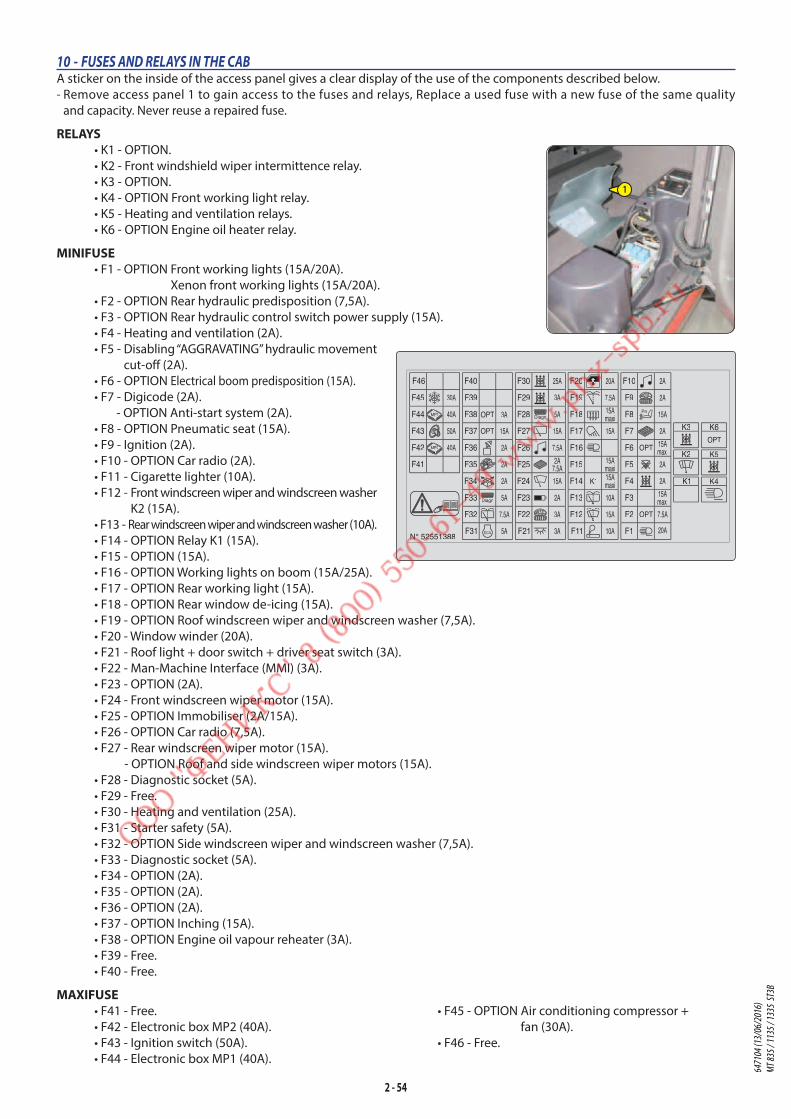
2 - 54
10 - FUSES AND RELAYS IN THE CABA sticker on the inside of the access panel gives a clear display of the use of the components described below.
- Remove access panel 1 to gain access to the fuses and relays, Replace a used fuse with a new fuse of the same quality
and capacity. Never reuse a repaired fuse.
RELAYS • K1 - OPTION.
• K2 - Front windshield wiper intermittence relay.
• K3 - OPTION.
• K4 - OPTION Front working light relay.
• K5 - Heating and ventilation relays.
• K6 - OPTION Engine oil heater relay.
MINIFUSE• F1 - OPTION Front working lights (15A/20A).
Xenon front working lights (15A/20A).
• F2 - OPTION Rear hydraulic predisposition (7,5A).
• F3 - OPTION Rear hydraulic control switch power supply (15A).
• F4 - Heating and ventilation (2A).
• F5 - Disabling “AGGRAVATING” hydraulic movement
cut-off (2A).
• F6 - OPTION Electrical boom predisposition (15A).
• F7 - Digicode (2A).
- OPTION Anti-start system (2A).
• F8 - OPTION Pneumatic seat (15A).
• F9 - Ignition (2A).
• F10 - OPTION Car radio (2A).
• F11 - Cigarette lighter (10A).
• F12 - Front windscreen wiper and windscreen washer
K2 (15A).
• F13 - Rear windscreen wiper and windscreen washer (10A).
• F14 - OPTION Relay K1 (15A).
• F15 - OPTION (15A).
• F16 - OPTION Working lights on boom (15A/25A).
• F17 - OPTION Rear working light (15A).
• F18 - OPTION Rear window de-icing (15A).
• F19 - OPTION Roof windscreen wiper and windscreen washer (7,5A).
• F20 - Window winder (20A).
• F21 - Roof light + door switch + driver seat switch (3A).
• F22 - Man-Machine Interface (MMI) (3A).
• F23 - OPTION (2A).
• F24 - Front windscreen wiper motor (15A).
• F25 - OPTION Immobiliser (2A/15A).
• F26 - OPTION Car radio (7,5A).
• F27 - Rear windscreen wiper motor (15A).
- OPTION Roof and side windscreen wiper motors (15A).
• F28 - Diagnostic socket (5A).
• F29 - Free.
• F30 - Heating and ventilation (25A).
• F31 - Starter safety (5A).
• F32 - OPTION Side windscreen wiper and windscreen washer (7,5A).
• F33 - Diagnostic socket (5A).
• F34 - OPTION (2A).
• F35 - OPTION (2A).
• F36 - OPTION (2A).
• F37 - OPTION Inching (15A).
• F38 - OPTION Engine oil vapour reheater (3A).
• F39 - Free.
• F40 - Free.
MAXIFUSE• F41 - Free.
• F42 - Electronic box MP2 (40A).
• F43 - Ignition switch (50A).
• F44 - Electronic box MP1 (40A).
• F45 - OPTION Air conditioning compressor +
fan (30A).
• F46 - Free.
F10
F9
F8
F7
F6
F5
F4
F3
F2
F1F11
F12
F13
F14
F15
F16
F17
F18
F19
F20F30
F29
F28
F27
F26
F25
F24
F23
F22
F21F31
F32
F33
F34
F35
F36
F37
F38
F39
F40
F41
F42
F43
F44
F45
F46
K3
K2
K1
K6
K5
K4
ECU
50A
40A
30A
40A
15Amaxi
15Amaxi
20A
7.5A
15A
10A
15A
10A
maxi15A
15A
2A
5A
7.5A
5A
2A
2A maxi
7.5A
2A
2A
15A
2A
15A
2A
2A
maxi15A
20A3A
3A
3A
2A
15A
2A
7.5A
7.5A
5A
25A
15A
OPTOPT
OPT
OPT
3AOPT
K1
MP1
MP22
N° 52551388
Diagn
Diagn
11
22
33
44
55
6677
88
99**
00
##
Pn
11
22
33
44
55
6677
88
99**
00
##
1
6471
04 (1
3/06
/201
6)
MT 83
5 / 11
35 / 1
335
ST3B

2 - 55
12 - DOOR PRESENCE SENSORS
See: 2 - DESCRIPTION: 6 - MAN-MACHINE INTERFACE (MMI).
13 - CIGARETTE LIGHTER
14 - LIGHTING, HORN AND INDICATOR SWITCH
The switch controls the visual and sound alarms.
• A - All lights are off, the direction indicators do not flash.
• B - The right hand direction indicators flash.
• C - The left hand direction indicators flash.
• D - The sidelights and the rear lights are on.
• E - The dipped headlights and the rear lights are on.
• F - The main beam headlights and the rear lights are on.
• G - Headlight signal.
Pressing the switch sounds the horn.
NOTE: Positions D - E - F - G can be used without the ignition being on.
15 - FRONT AND REAR WINDSCREEN WIPER
SWITCH
FRONT WINDSCREEN WIPER
• A - Front windscreen wiper stop.
• B - Slow speed for front windscreen wiper.
• C - Fast speed for front windscreen wiper.
• D - Front windscreen wiper intermittent
control.
• E - Front windscreen washer, pulse-driven.
REAR WINDSCREEN WIPER
• F - Rear windscreen wiper stop.
• G - Rear windscreen wiper.
• H - Rear windscreen washer, pulse-driven.
F E G
G
GA
D
B
C
E
E
E
D
B
C
A
B
C
G
F H
11 - FUSES AND RELAYS UNDER THE ENGINE HOOD - Open engine hood 1 in order to gain access to the fuses and relays. Replace a used
fuse with a new fuse of the same quality and capacity. Never reuse a repaired fuse.
RELAYS• K21 - Engine computer power supply relay.
• K22 - Starter control relay.
MAXIFUSE• F51 - Starter control relay K22 (30A).
• F52 - Engine preheating module (60A).
• F53 - Engine computer power supply relay (40A).
MINIFUSE• F54 - Engine computer power supply (25A).
• F55 - Engine computer power supply (5A).
• F56 - Engine computer relay control (5A).
• F57 - Lambda probe + diagnostic socket (5A).
1
6471
04 (1
3/06
/201
6)
MT 83
5 / 11
35 / 1
335
ST3B

2 - 56
16 - FUNCTION FILES
These files contain the description of the hydraulic controls and the load charts for the attachments used on the lift truck.
17 - HYDRAULIC CONTROLS
Authorization for using the hydraulic controls is given by the validation of the driver’s presence (see: 2 - DESCRIPTION: 6 -
MAN-MACHINE INTERFACE (MMI)) and if the conditions for using the hydraulic control are followed.
IMPORTANT
Do not attempt to alter the hydraulic system pressure. In the event of suspected malfunction, contact your dealer. ANY ALTERATION MAY RENDER THE WARRANTY NULL
AND VOID.
Use the hydraulic controls carefully without jerking, to avoid accidents caused by shaking the lift truck.
MT 835 ST3B• A - Lifting and tilting control lever.
• B - Telescoping control button.
• C - Attachment control button.
LIFTING THE LOAD - The lever A backwards when lifting.
- The lever A forwards when lowering.
TILT OF CARRIAGE - The lever A to the left for reverse tilt.
- The lever A to the right for forward tilt.
TELESCOPING - Button B forwards for extending.
- Button B backwards for retracting.
ATTACHMENT - Button C forwards or backwards.
A
BC
N°309499
6471
04 (1
3/06
/201
6)
MT 83
5 / 11
35 / 1
335
ST3B

2 - 57
MT 1135 ST3BMT 1335 ST3B• A - Lifting and tilting control lever.
• B - Telescoping control button.
• C - Left stabiliser control lever.
• D - Right stabiliser control lever.
• E - Tilting corrector control lever.
• F - Attachment control button.
LIFTING THE LOAD - The lever A backwards when lifting.
- The lever A forwards when lowering.
TILT OF CARRIAGE - The lever A to the left for reverse tilt.
- The lever A to the right for forward tilt.
TELESCOPING - Button B forwards for extending.
- Button B backwards for retracting.
Only for MT 1335 ST3BNOTE: When completely retracting the telescopes,
insistently operate the control so as to allow
all the telescopes to retract fully.
L.H. STABILISER - Move lever C forwards to lower.
- Move lever C backwards to lift.
R.H. STABILISER - Move lever D forwards for lowering.
- Move lever D backwards for lifting.
NOTE: The stabilisers can only be raised if the telescopic
sections are retracted and the lifting angle of
the boom is less than 62°.
TILTING CORRECTOR - Move lever E to the left to tilt the lift truck to the left.
- Move lever E to the right to tilt the lift truck to the
right.
NOTE: The tilt correction may only be performed if
the lifting angle for the boom is less than 30°.
ATTACHMENT - Button F forwards or backwards.
18 - ACCELERATOR PEDAL
19 - SERVICE BRAKE PEDAL
The pedal acts on the front and rear wheels by a power assisted hydraulic brake system, and allows the lift truck to be slowed
down and stopped.
N°310973
AB
CD
E
F
6471
04 (1
3/06
/201
6)
MT 83
5 / 11
35 / 1
335
ST3B
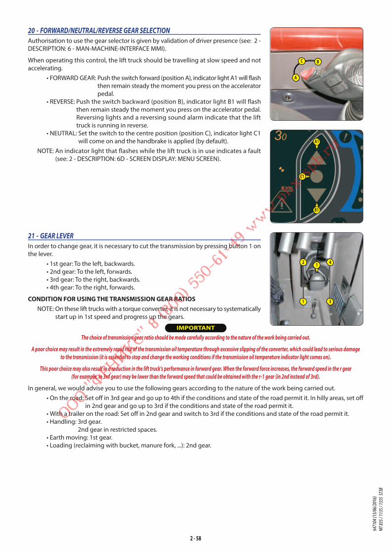
2 - 58
21 - GEAR LEVER
In order to change gear, it is necessary to cut the transmission by pressing button 1 on
the lever.
• 1st gear: To the left, backwards.
• 2nd gear: To the left, forwards.
• 3rd gear: To the right, backwards.
• 4th gear: To the right, forwards.
CONDITION FOR USING THE TRANSMISSION GEAR RATIOSNOTE: On these lift trucks with a torque converter, it is not necessary to systematically
start up in 1st speed and progress up the gears.
IMPORTANT
The choice of transmission gear ratio should be made carefully according to the nature of the work being carried out.
A poor choice may result in the extremely rapid rise of the transmission oil temperature through excessive slipping of the converter, which could lead to serious damage
to the transmission (it is essential to stop and change the working conditions if the transmission oil temperature indicator light comes on).
This poor choice may also result in a reduction in the lift truck's performance in forward gear. When the forward force increases, the forward speed in the r gear
(for example, in 3rd gear) may be lower than the forward speed that could be obtained with the r-1 gear (in 2nd instead of 3rd).
In general, we would advise you to use the following gears according to the nature of the work being carried out.
• On the road: Set off in 3rd gear and go up to 4th if the conditions and state of the road permit it. In hilly areas, set off
in 2nd gear and go up to 3rd if the conditions and state of the road permit it.
• With a trailer on the road: Set off in 2nd gear and switch to 3rd if the conditions and state of the road permit it.
• Handling: 3rd gear.
2nd gear in restricted spaces.
• Earth moving: 1st gear.
• Loading (reclaiming with bucket, manure fork, ...): 2nd gear.
20 - FORWARD/NEUTRAL/REVERSE GEAR SELECTION
Authorisation to use the gear selector is given by validation of driver presence (see: 2 -
DESCRIPTION: 6 - MAN-MACHINE-INTERFACE MMI).
When operating this control, the lift truck should be travelling at slow speed and not
accelerating.
• FORWARD GEAR: Push the switch forward (position A), indicator light A1 will flash
then remain steady the moment you press on the accelerator
pedal.
• REVERSE: Push the switch backward (position B), indicator light B1 will flash
then remain steady the moment you press on the accelerator pedal.
Reversing lights and a reversing sound alarm indicate that the lift
truck is running in reverse.
• NEUTRAL: Set the switch to the centre position (position C), indicator light C1
will come on and the handbrake is applied (by default).
NOTE: An indicator light that flashes while the lift truck is in use indicates a fault
(see: 2 - DESCRIPTION: 6D - SCREEN DISPLAY: MENU SCREEN).
2
1
4
3
1
B1
A1
C1
A
C B
6471
04 (1
3/06
/201
6)
MT 83
5 / 11
35 / 1
335
ST3B
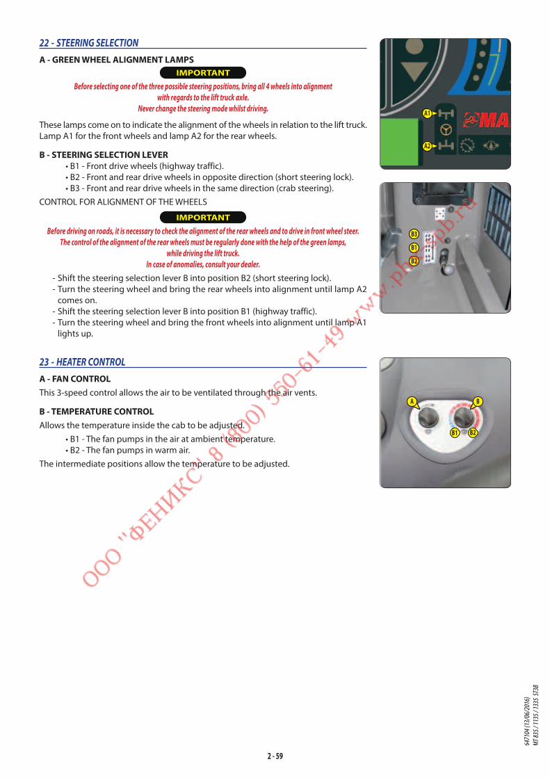
2 - 59
22 - STEERING SELECTION
A - GREEN WHEEL ALIGNMENT LAMPS IMPORTANT
Before selecting one of the three possible steering positions, bring all 4 wheels into alignment
with regards to the lift truck axle.
Never change the steering mode whilst driving.
These lamps come on to indicate the alignment of the wheels in relation to the lift truck.
Lamp A1 for the front wheels and lamp A2 for the rear wheels.
B - STEERING SELECTION LEVER• B1 - Front drive wheels (highway traffic).
• B2 - Front and rear drive wheels in opposite direction (short steering lock).
• B3 - Front and rear drive wheels in the same direction (crab steering).
CONTROL FOR ALIGNMENT OF THE WHEELS
IMPORTANT
Before driving on roads, it is necessary to check the alignment of the rear wheels and to drive in front wheel steer.
The control of the alignment of the rear wheels must be regularly done with the help of the green lamps,
while driving the lift truck.
In case of anomalies, consult your dealer.
- Shift the steering selection lever B into position B2 (short steering lock).
- Turn the steering wheel and bring the rear wheels into alignment until lamp A2
comes on.
- Shift the steering selection lever B into position B1 (highway traffic).
- Turn the steering wheel and bring the front wheels into alignment until lamp A1
lights up.
23 - HEATER CONTROL
A - FAN CONTROLThis 3-speed control allows the air to be ventilated through the air vents.
B - TEMPERATURE CONTROLAllows the temperature inside the cab to be adjusted.
• B1 - The fan pumps in the air at ambient temperature.
• B2 - The fan pumps in warm air.
The intermediate positions allow the temperature to be adjusted.
A B
B1 B2
A1
A2
B3
B1
B2
6471
04 (1
3/06
/201
6)
MT 83
5 / 11
35 / 1
335
ST3B
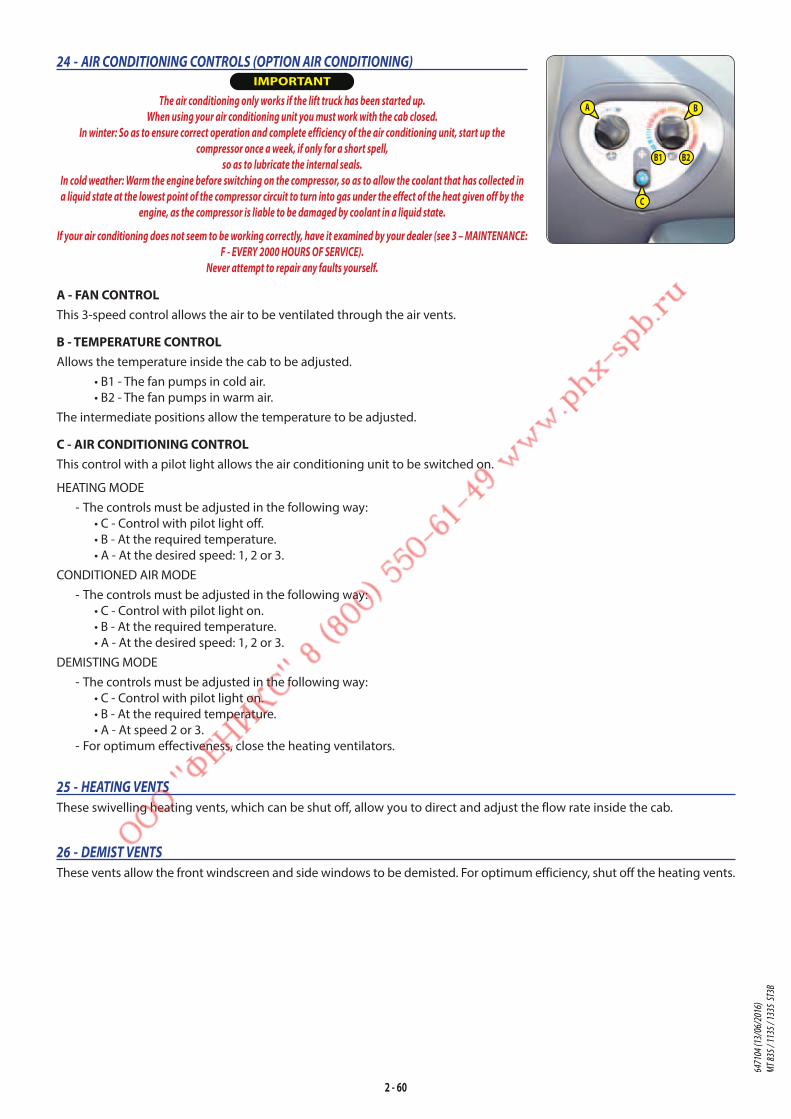
2 - 60
24 - AIR CONDITIONING CONTROLS (OPTION AIR CONDITIONING) IMPORTANT
The air conditioning only works if the lift truck has been started up.
When using your air conditioning unit you must work with the cab closed.
In winter: So as to ensure correct operation and complete efficiency of the air conditioning unit, start up the
compressor once a week, if only for a short spell,
so as to lubricate the internal seals.
In cold weather: Warm the engine before switching on the compressor, so as to allow the coolant that has collected in
a liquid state at the lowest point of the compressor circuit to turn into gas under the effect of the heat given off by the
engine, as the compressor is liable to be damaged by coolant in a liquid state.
If your air conditioning does not seem to be working correctly, have it examined by your dealer (see 3 – MAINTENANCE:
F - EVERY 2000 HOURS OF SERVICE).
Never attempt to repair any faults yourself.
A - FAN CONTROLThis 3-speed control allows the air to be ventilated through the air vents.
B - TEMPERATURE CONTROLAllows the temperature inside the cab to be adjusted.
• B1 - The fan pumps in cold air.
• B2 - The fan pumps in warm air.
The intermediate positions allow the temperature to be adjusted.
C - AIR CONDITIONING CONTROLThis control with a pilot light allows the air conditioning unit to be switched on.
HEATING MODE
- The controls must be adjusted in the following way:
• C - Control with pilot light off.
• B - At the required temperature.
• A - At the desired speed: 1, 2 or 3.
CONDITIONED AIR MODE
- The controls must be adjusted in the following way:
• C - Control with pilot light on.
• B - At the required temperature.
• A - At the desired speed: 1, 2 or 3.
DEMISTING MODE
- The controls must be adjusted in the following way:
• C - Control with pilot light on.
• B - At the required temperature.
• A - At speed 2 or 3.
- For optimum effectiveness, close the heating ventilators.
25 - HEATING VENTS
These swivelling heating vents, which can be shut off, allow you to direct and adjust the flow rate inside the cab.
26 - DEMIST VENTS
These vents allow the front windscreen and side windows to be demisted. For optimum efficiency, shut off the heating vents.
A B
B1 B2
C
6471
04 (1
3/06
/201
6)
MT 83
5 / 11
35 / 1
335
ST3B

2 - 61
34 - HANDLE FOR REAR WINDOW CLOSING
28 - DOOR OPEN LEVER
29 - DOOR CLOSE HANDLE
30 - WINDOW REGULATOR SWITCH
31 - SIDE STORAGE SPACE
32 - CEILING LIGHT
33 - HANDLE FOR REAR WINDOW OPENING
EMERGENCY EXIT - Use the rear window as an emergency exit, if it is impossible to leave the cab
by the door.
27 - LEVEL INDICATORS
A - TILT INDICATORMT 1135 ST3B / MT 1335 ST3B
When the two marks are aligned, the chassis is
parallel with the front axle.
B - SPIRIT LEVELEnables the operator to check that the lift truck
is in the horizontal position.
35 - STEERING WHEEL ADJUSTMENT LEVER
This handle enables the angle and height of the steering wheel to be adjusted.
- Pull the knob backwards.
- Adjust the steering wheel to the desired position.
- Push the knob back to lock the steering wheel in position.
A
B
6471
04 (1
3/06
/201
6)
MT 83
5 / 11
35 / 1
335
ST3B

2 - 62
39 - REAR LIGHTS• A -Left rear indicator light.
• B - Left rear stoplight.
• C - Left rear headlight.
• D - Rear fog light.
• E - Rear reversing light.
• F - Right rear headlight.
• G - Right rear stoplight.
• H - Right rear indicator light.
IMPORTANT
When driving on the road, widen the rear lights by means of the thumbscrews 1.
• I - Handling position.
• J - Road driving position.
36 - DOCUMENT HOLDER NET
Make sure that the operator’s manual is in the right place, i.e. in the document holder net.
NOTE: An OPTION waterproof document-holder exists.
37 - ASHTRAY
38 - FRONT HEADLIGHTS• A - Left front indicator light.
• B - Left front dipped beam headlight.
• C - Left front main beam headlight.
• D - Left front sidelight.
• E - Right front indicator light.
• F - Right front dipped beam headlight.
• G - Right front main beam headlight.
• H - Right front sidelight.
H
E G
F11
A
B D
C1 1
J
I
J
I
A
B
C
DH
F
G
E
6471
04 (1
3/06
/201
6)
MT 83
5 / 11
35 / 1
335
ST3B
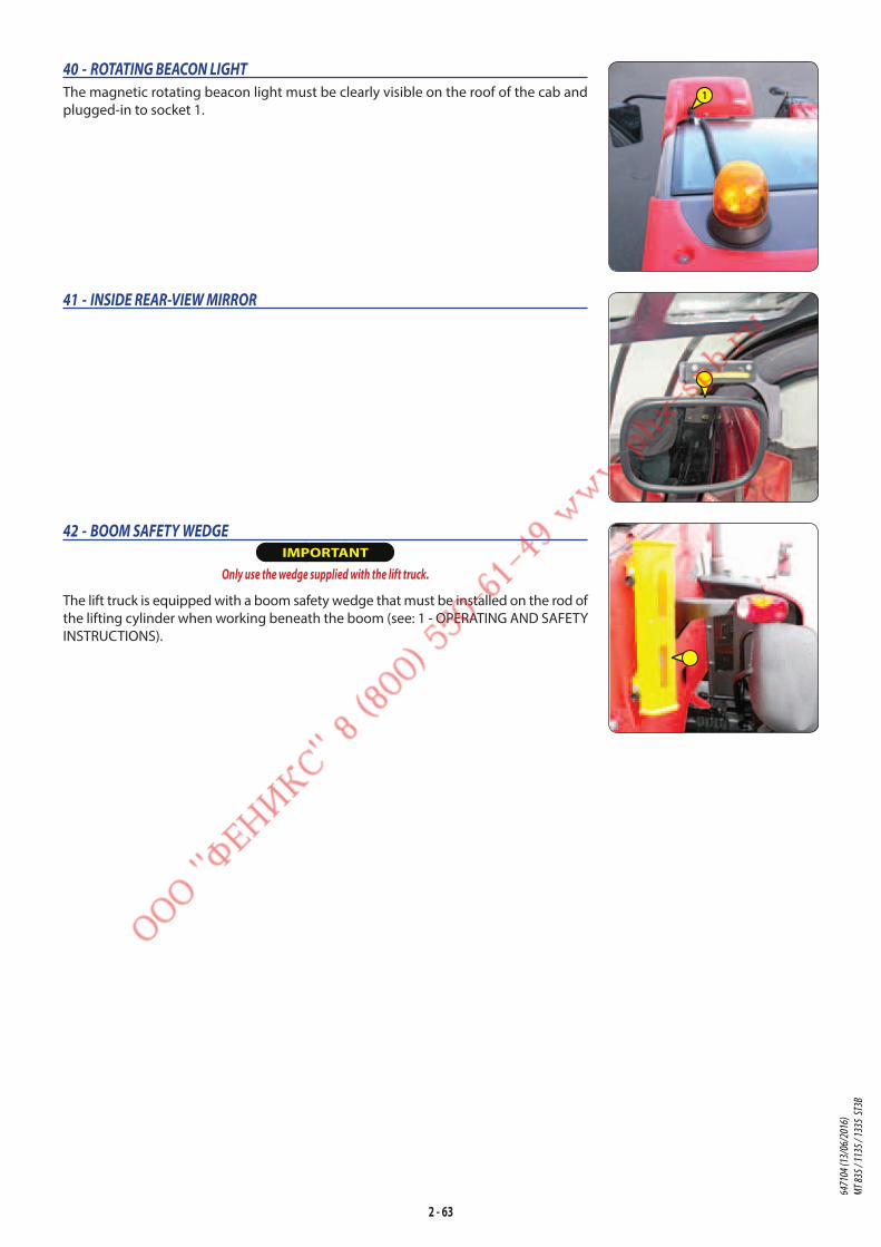
2 - 63
40 - ROTATING BEACON LIGHT
The magnetic rotating beacon light must be clearly visible on the roof of the cab and
plugged-in to socket 1.
41 - INSIDE REAR-VIEW MIRROR
42 - BOOM SAFETY WEDGE IMPORTANT
Only use the wedge supplied with the lift truck.
The lift truck is equipped with a boom safety wedge that must be installed on the rod of
the lifting cylinder when working beneath the boom (see: 1 - OPERATING AND SAFETY
INSTRUCTIONS).
1
6471
04 (1
3/06
/201
6)
MT 83
5 / 11
35 / 1
335
ST3B

2 - 64
TOWING PIN AND HOOK
IMPORTANT
Do not tow a trailer or attachment which is not in perfect working order.
Using a trailer in poor condition may affect the lift truck’s steering and braking, and hence safety.
If a third party helps in coupling or uncoupling the trailer, this person must be permanently visible to the driver and wait until the lift truck has stopped, the handbrake is
on and the I.C. engine is switched off before performing the operation.
Located at the rear of the lift truck, this device is used to attach a trailer. Its capacity is limited for each lift truck by the
authorized gross vehicle weight, tractive effort and maximum vertical force on the coupling point. This information is given
on the manufacturer’s plate fixed to each lift truck (see: 2 - DESCRIPTION: IDENTIFICATION OF THE LIFT TRUCK).
- To use a trailer, see current regulations in your country (maximum running speed, braking, maximum weight of trailer, etc.).
- Verify the trailer’s condition before using it (tyre condition and pressures, electrical connection, hydraulic hose, brake
system…).
1 - TOWING PIN IMPORTANT
Be careful not to get your fingers caught or crushed during this operation.
Do not forget to put pin back in place.
When uncoupling, make sure that the trailer is supported independently.
COUPLING AND UNCOUPLING THE TRAILER - To couple the trailer, position the lift truck as close as possible to the trailer ring.
- Switch off the I.C. engine.
- Remove the pin 1, lift the trailer pin 2 and place or remove the trailer ring.
2 - ADJUSTABLE PROJECTING HOOK (OPTION) IMPORTANT
Be careful not to get your fingers caught or crushed during this operation.
Do not forget to put pin back in place.
When uncoupling, make sure that the trailer is supported independently.
COUPLING AND UNCOUPLING THE TRAILER - To couple the trailer, position the lift truck as close as possible to the trailer ring.
- Switch off the I.C. engine.
- Set the coupling fitting 1 according to the height of the trailer ring.
- Remove pin 2, lift the trailer pin 3 and place or remove the trailer ring.
3 - REAR ELECTRIC SOCKET (OPTION) - Connect the male plug to the female socket 1 on the lift truck and make sure the
lights of the trailer or the light bar are working properly.
• A - Left rear indicator.
• B - OPTION Rear fog lights.
• C - Earth.
• D - Right rear indicator.
• E - Right tail light.
• F - Rear stoplight.
• G - Left rear light + number plate.
A
G
C
B
D
E
F
1
1
2
1
2
3
6471
04 (1
3/06
/201
6)
MT 83
5 / 11
35 / 1
335
ST3B

2 - 65
6471
04 (1
3/06
/201
6)
MT 83
5 / 11
35 / 1
335
ST3B

2 - 66
DESCRIPTION AND USE OF THE OPTIONS
1 - LICENSE PLATE LIGHT
2 - MODCLE ANTI-START SYSTEM
3 - BOOM ELECTRICAL PREDISPOSITION
4 - QUICK-RELEASE COUPLER ON ATTACHMENT CIRCUIT
5 - ANGULAR SECTOR ON BOOM
6 - EXTERIOR DRAIN-BACK
7 - ATTACHMENT HYDRAULIC LOCKING
8 - TELESCOPE HEAD ELECTROVALVE
9 - TELESCOPE HEAD ELECTROVALVE + HYDRAULIC ATTACHMENT LOCKING
10 - SINGLE SIDE-SHIFT CARRIAGE (TSDL)
11 - SINGLE OR DUAL EFFECT REAR HYDRAULIC CONTROL PREDISPOSITION
12 - LIFTING RING ON SINGLE CARRIAGE
1 - LICENSE PLATE LIGHT
2 - MODCLE ANTI-START SYSTEM
OPERATION - Switch on lift truck ignition, red led 1 will flash.
- Apply key 2 to its base 3, and withdraw the moment the system emits a continuous
beep, and led 1 turns green.
- Start the lift truck within the next 20 seconds; otherwise the anti-theft system will
be reactivated and red led 1 will flash.
NOTE: You can restart the lift truck within 20 seconds of stopping it: after this time,
the anti-start system reacts and red LED C flashes.
6471
04 (1
3/06
/201
6)
MT 83
5 / 11
35 / 1
335
ST3B
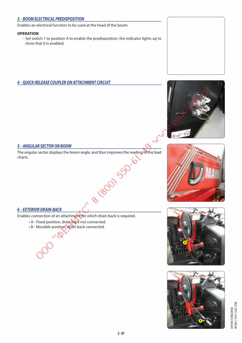
2 - 67
4 - QUICK-RELEASE COUPLER ON ATTACHMENT CIRCUIT
6 - EXTERIOR DRAIN-BACK
Enables connection of an attachment for which drain-back is required.
• A - Fixed position, drain back not connected.
• B - Movable position, drain back connected.
5 - ANGULAR SECTOR ON BOOM
The angular sector displays the boom angle, and thus improves the reading of the load
charts.
3 - BOOM ELECTRICAL PREDISPOSITION
Enables an electrical function to be used at the head of the boom.
OPERATION - Set switch 1 to position A to enable the predisposition, the indicator lights up to
show that it is enabled.
B
A
6471
04 (1
3/06
/201
6)
MT 83
5 / 11
35 / 1
335
ST3B
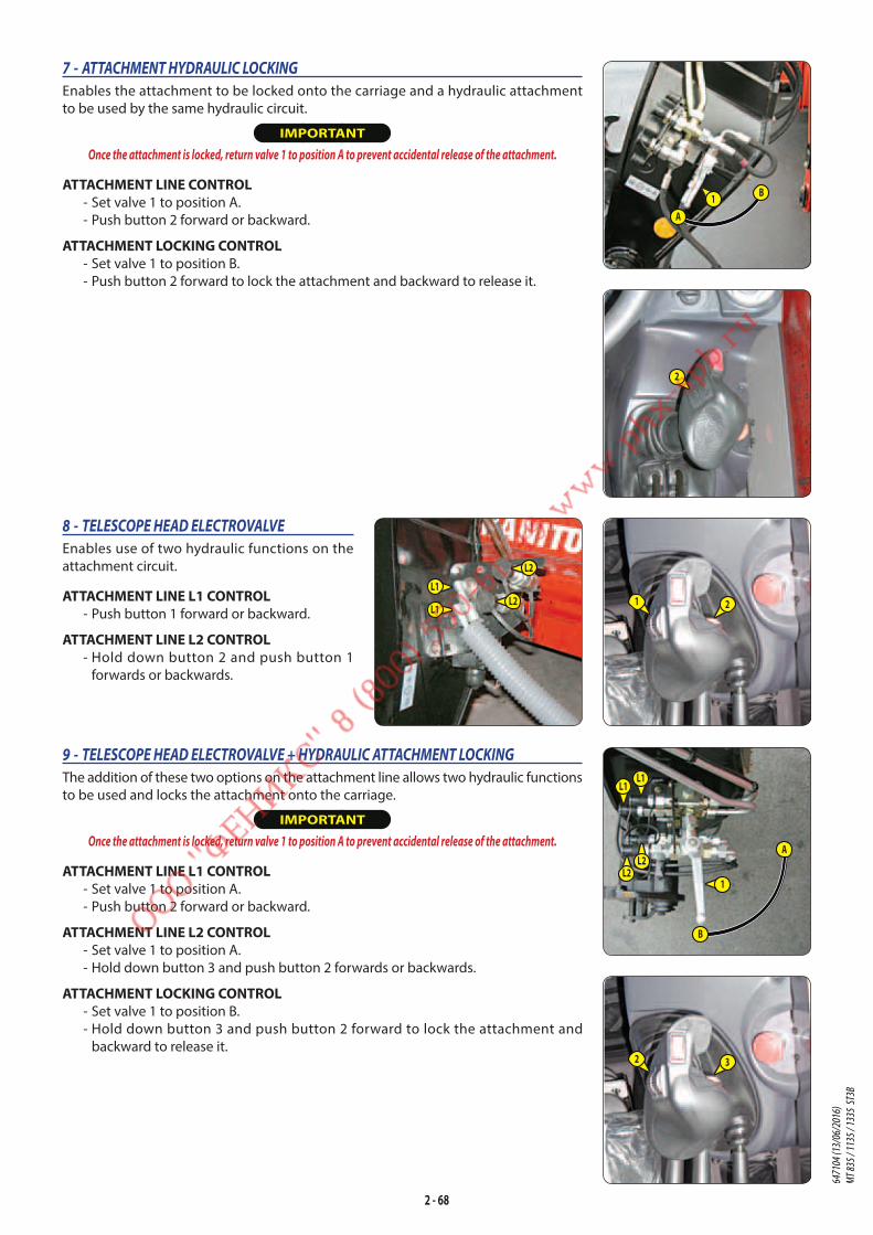
2 - 68
7 - ATTACHMENT HYDRAULIC LOCKING
Enables the attachment to be locked onto the carriage and a hydraulic attachment
to be used by the same hydraulic circuit.
IMPORTANT
Once the attachment is locked, return valve 1 to position A to prevent accidental release of the attachment.
ATTACHMENT LINE CONTROL - Set valve 1 to position A.
- Push button 2 forward or backward.
ATTACHMENT LOCKING CONTROL - Set valve 1 to position B.
- Push button 2 forward to lock the attachment and backward to release it.
8 - TELESCOPE HEAD ELECTROVALVE
Enables use of two hydraulic functions on the
attachment circuit.
ATTACHMENT LINE L1 CONTROL - Push button 1 forward or backward.
ATTACHMENT LINE L2 CONTROL - Hold down button 2 and push button 1
forwards or backwards.
9 - TELESCOPE HEAD ELECTROVALVE + HYDRAULIC ATTACHMENT LOCKING
The addition of these two options on the attachment line allows two hydraulic functions
to be used and locks the attachment onto the carriage.
IMPORTANT
Once the attachment is locked, return valve 1 to position A to prevent accidental release of the attachment.
ATTACHMENT LINE L1 CONTROL - Set valve 1 to position A.
- Push button 2 forward or backward.
ATTACHMENT LINE L2 CONTROL - Set valve 1 to position A.
- Hold down button 3 and push button 2 forwards or backwards.
ATTACHMENT LOCKING CONTROL - Set valve 1 to position B.
- Hold down button 3 and push button 2 forward to lock the attachment and
backward to release it.
B
A1
2
L1
L1
L2
L2 1 2
2 3
B
A
1
L2L2
L1L1
6471
04 (1
3/06
/201
6)
MT 83
5 / 11
35 / 1
335
ST3B
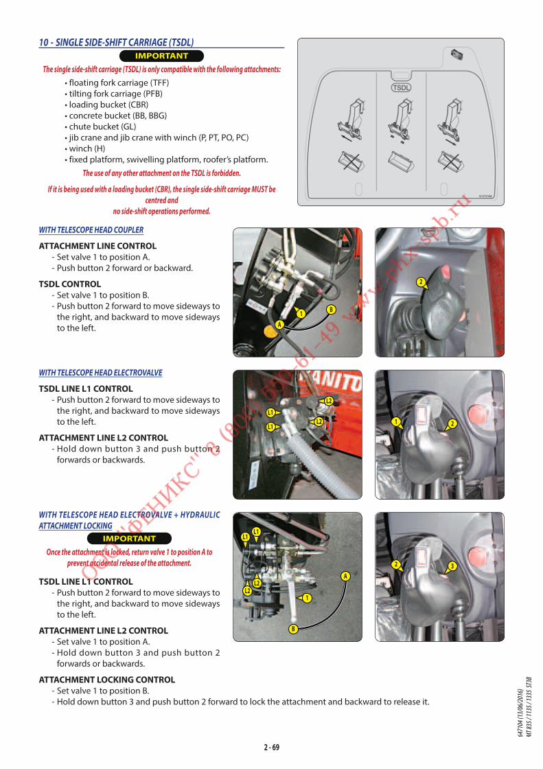
2 - 69
10 - SINGLE SIDE-SHIFT CARRIAGE (TSDL) IMPORTANT
The single side-shift carriage (TSDL) is only compatible with the following attachments:
• floating fork carriage (TFF)
• tilting fork carriage (PFB)
• loading bucket (CBR)
• concrete bucket (BB, BBG)
• chute bucket (GL)
• jib crane and jib crane with winch (P, PT, PO, PC)
• winch (H)
• fixed platform, swivelling platform, roofer’s platform.
The use of any other attachment on the TSDL is forbidden.
If it is being used with a loading bucket (CBR), the single side-shift carriage MUST be
centred and
no side-shift operations performed.
WITH TELESCOPE HEAD COUPLER
ATTACHMENT LINE CONTROL - Set valve 1 to position A.
- Push button 2 forward or backward.
TSDL CONTROL - Set valve 1 to position B.
- Push button 2 forward to move sideways to
the right, and backward to move sideways
to the left.
WITH TELESCOPE HEAD ELECTROVALVE
TSDL LINE L1 CONTROL - Push button 2 forward to move sideways to
the right, and backward to move sideways
to the left.
ATTACHMENT LINE L2 CONTROL - Hold down button 3 and push button 2
forwards or backwards.
WITH TELESCOPE HEAD ELECTROVALVE + HYDRAULIC
ATTACHMENT LOCKING
IMPORTANT
Once the attachment is locked, return valve 1 to position A to
prevent accidental release of the attachment.
TSDL LINE L1 CONTROL - Push button 2 forward to move sideways to
the right, and backward to move sideways
to the left.
ATTACHMENT LINE L2 CONTROL - Set valve 1 to position A.
- Hold down button 3 and push button 2
forwards or backwards.
ATTACHMENT LOCKING CONTROL - Set valve 1 to position B.
- Hold down button 3 and push button 2 forward to lock the attachment and backward to release it.
B
A1
2
L1
L1
L2
L2 1 2
2 3
B
A
1
L2L2
L1L1
6471
04 (1
3/06
/201
6)
MT 83
5 / 11
35 / 1
335
ST3B
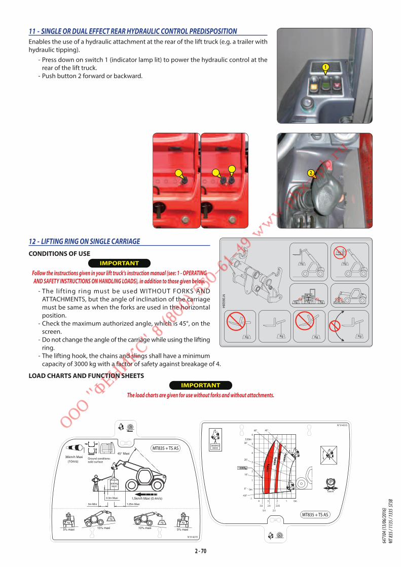
2 - 70
11 - SINGLE OR DUAL EFFECT REAR HYDRAULIC CONTROL PREDISPOSITION
Enables the use of a hydraulic attachment at the rear of the lift truck (e.g. a trailer with
hydraulic tipping).
- Press down on switch 1 (indicator lamp lit) to power the hydraulic control at the
rear of the lift truck.
- Push button 2 forward or backward.
12 - LIFTING RING ON SINGLE CARRIAGE
CONDITIONS OF USE IMPORTANT
Follow the instructions given in your lift truck's instruction manual (see: 1 - OPERATING
AND SAFETY INSTRUCTIONS ON HANDLING LOADS), in addition to those given below.
- The lifting ring must be used WITHOUT FORKS AND
ATTACHMENTS, but the angle of inclination of the carriage
must be same as when the forks are used in the horizontal
position.
- Check the maximum authorized angle, which is 45°, on the
screen.
- Do not change the angle of the carriage while using the lifting
ring.
- The lifting hook, the chains and slings shall have a minimum
capacity of 3000 kg with a factor of safety against breakage of 4.
LOAD CHARTS AND FUNCTION SHEETS IMPORTANT
The load charts are given for use without forks and without attachments.
2N°265284
KgKg KgKg
Kg Kg Kg Kg Kg Kg
Kg Kg
Kg
1
6471
04 (1
3/06
/201
6)
MT 83
5 / 11
35 / 1
335
ST3B

2 - 71
Ground conditions:solid surface
3500KGMAXI
3500KGMAXI
36km/h Maxi (10m/s)
kgkg
kg kg
5% maxi 15% maxi 10% maxi 5% maxi
45° Maxi
1,5km/h Maxi (0,4m/s)
N°319881
N°319881
MT1335 + TS AS
MT1335 + TS AS
3m Mini 1.55m Maxi
0.3m Maxi
8.84m
7.92
6.3
4.85
4.3
3.8
3.35
2.85
2.3 1.45
0m124 35678
0
1
2
3
4
5
6
7
8
9
-1
A
B
C
D
E
200K
G 400K
G 600K
G 800K
G10
00KG
1200
KG16
00KG
2000
KG
3500
KG
3.7°
0°
10°
20°
30°
40° 45°
6471
04 (1
3/06
/201
6)
MT 83
5 / 11
35 / 1
335
ST3B

2 - 72
6471
04 (1
3/06
/201
6)
MT 83
5 / 11
35 / 1
335
ST3B

3 - 1
3 - MAINTENANCE
6471
04 (1
3/06
/201
6)
MT 83
5 / 11
35 / 1
335
ST3B

3 - 2
6471
04 (1
3/06
/201
6)
MT 83
5 / 11
35 / 1
335
ST3B
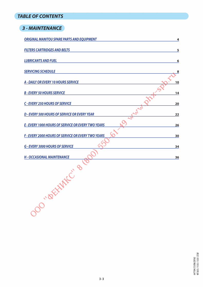
3 - 3
TABLE OF CONTENTS
3 - MAINTENANCE
ORIGINAL MANITOU SPARE PARTS AND EQUIPMENT 4
FILTERS CARTRIDGES AND BELTS 5
LUBRICANTS AND FUEL 6
SERVICING SCHEDULE 8
A - DAILY OR EVERY 10 HOURS SERVICE 10
B - EVERY 50 HOURS SERVICE 14
C - EVERY 250 HOURS OF SERVICE 20
D - EVERY 500 HOURS OF SERVICE OR EVERY YEAR 22
E - EVERY 1000 HOURS OF SERVICE OR EVERY TWO YEARS 26
F - EVERY 2000 HOURS OF SERVICE OR EVERY TWO YEARS 30
G - EVERY 3000 HOURS OF SERVICE 34
H - OCCASIONAL MAINTENANCE 36
6471
04 (1
3/06
/201
6)
MT 83
5 / 11
35 / 1
335
ST3B

3 - 4
ORIGINAL MANITOU SPARE PARTS AND EQUIPMENTOUR LIFT TRUCKS MUST BE SERVICED USING ORIGINAL MANITOU PARTS.
BY ALLOWING THE USE OF NON ORIGINAL MANITOU PARTS, YOU RISK:
• Legally -to be held responsible in the event of an accident.
• Technically - to cause operating malfunctions or shorten the life of the lift truck.
IMPORTANT
THE USE OF COUNTERFEIT PARTS OR COMPONENTS NOT APPROVED BY THE MANUFACTURER,
WILL CAUSE YOU TO LOSE THE BENEFIT OF THE CONTRACTUAL GUARANTEE.
BY USING ORIGINAL MANITOU PARTS FOR MAINTENANCE OPERATIONS, YOU BENEFIT FROM OUR KNOW-HOW
Through its network, MANITOU provides the user with,
• Know-how and competence.
• The guarantee of high-quality work.
• Original replacement parts.
• Help with preventive maintenance.
• Efficient help with diagnosis.
• Improvements due to experience feedback.
• Operator training.
• Only the MANITOU network has detailed knowledge of the design of the lift truck and therefore the best technical
ability to provide maintenance.
IMPORTANT
ORIGINAL REPLACEMENT PARTS ARE DISTRIBUTED EXCLUSIVELY BY MANITOU AND ITS DEALER NETWORK.
The dealer network list is available on the MANITOU web site www.manitou.com
6471
04 (1
3/06
/201
6)
MT 83
5 / 11
35 / 1
335
ST3B
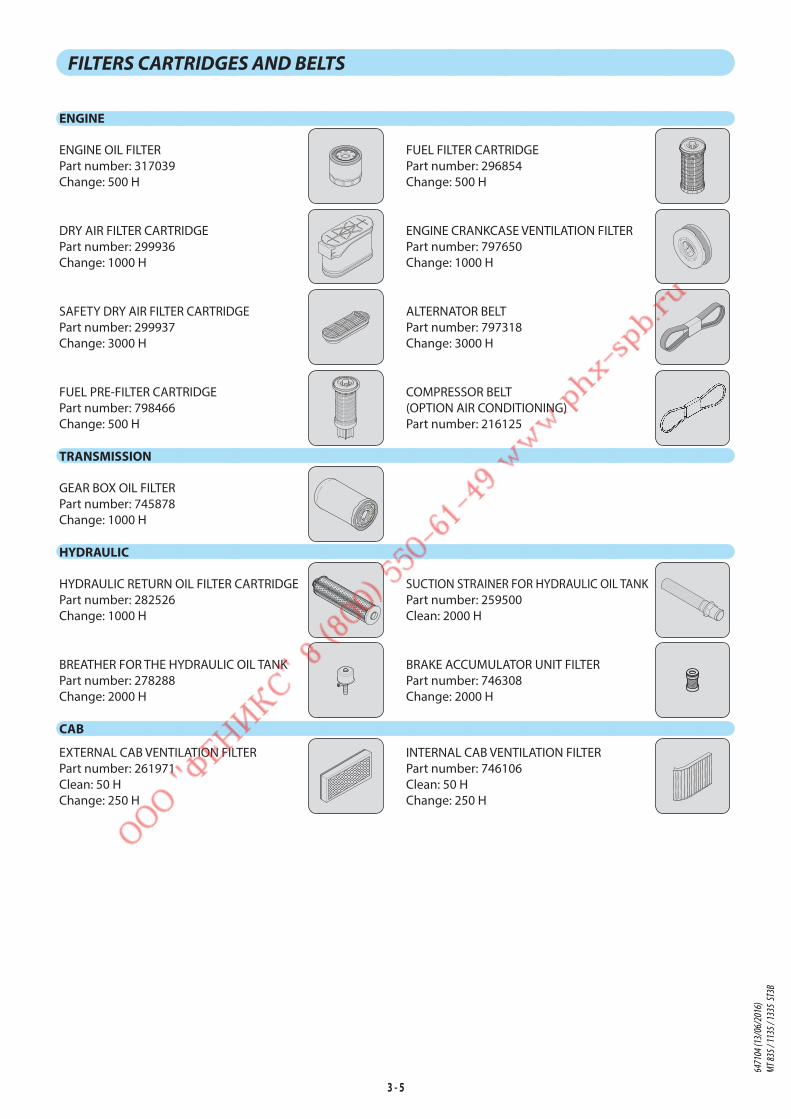
3 - 5
FILTERS CARTRIDGES AND BELTS
ENGINE
ENGINE OIL FILTER
Part number: 317039
Change: 500 H
FUEL FILTER CARTRIDGE
Part number: 296854
Change: 500 H
DRY AIR FILTER CARTRIDGE
Part number: 299936
Change: 1000 H
ENGINE CRANKCASE VENTILATION FILTER
Part number: 797650
Change: 1000 H
SAFETY DRY AIR FILTER CARTRIDGE
Part number: 299937
Change: 3000 H
ALTERNATOR BELT
Part number: 797318
Change: 3000 H
FUEL PRE-FILTER CARTRIDGE
Part number: 798466
Change: 500 H
COMPRESSOR BELT
(OPTION AIR CONDITIONING)
Part number: 216125
TRANSMISSION
GEAR BOX OIL FILTER
Part number: 745878
Change: 1000 H
HYDRAULIC
HYDRAULIC RETURN OIL FILTER CARTRIDGE
Part number: 282526
Change: 1000 H
SUCTION STRAINER FOR HYDRAULIC OIL TANK
Part number: 259500
Clean: 2000 H
BREATHER FOR THE HYDRAULIC OIL TANK
Part number: 278288
Change: 2000 H
BRAKE ACCUMULATOR UNIT FILTER
Part number: 746308
Change: 2000 H
CAB
EXTERNAL CAB VENTILATION FILTER
Part number: 261971
Clean: 50 H
Change: 250 H
INTERNAL CAB VENTILATION FILTER
Part number: 746106
Clean: 50 H
Change: 250 H
6471
04 (1
3/06
/201
6)
MT 83
5 / 11
35 / 1
335
ST3B

3 - 6
LUBRICANTS AND FUEL
IMPORTANT
USE THE RECOMMENDED LUBRICANTS AND FUEL:
- For topping up, oils may not be miscible.
- For oil changes, MANITOU oils are perfectly appropriate.
DIAGNOSTIC ANALYSIS OF OILSIf a service or maintenance contract has been organized with the dealer, a diagnostic analysis of engine, transmission and axle
oils may be requested depending on the rate of use.
(*) REQUIRED FUEL SPECIFICATIONUse a high-quality fuel to obtain optimal performance of the engine.
• EN590 diesel fuel (sulfur content < 10 ppm)
• ASTM D975 diesel fuel (sulfur content < 15 ppm)
RECOMMENDATION
I.C. ENGINEPARTS TO BE LUBRICATED CAPACITY RECOMMENDATION
-40°C -30 -20 -10 0 +10 +20 +30 +40 +50°C
0W200W30
0W405W30
5W4010W30
I.C. ENGINE 7,5 Liters MANITOU EVOLOGY OIL 10W40 API CJ415W40
-40°C -30 -20 -10 0 +10 +20 +30 +40 +50°C
COOLING CIRCUIT 17 Liters COOLING LIQUID -35°C-40°C -30 -20 -10 0 +10 +20 +30 +40 +50°C
FUEL TANK 120 Liters GNR HP DIESEL *
TRANSMISSIONPARTS TO BE LUBRICATED CAPACITY RECOMMENDATION
-40°C -30 -20 -10 0 +10 +20 +30 +40 +50°C
GEAR BOX 21,1 Liters MANITOU AUTOMATIC TRANSMISSION OIL DX IIIG
BOOMPARTS TO BE LUBRICATED RECOMMENDATION
-40°C -30 -20 -10 0 +10 +20 +30 +40 +50°C
BOOM PADS MANITOU BLACK MULTI-USE LUBRICANT-40°C -30 -20 -10 0 +10 +20 +30 +40 +50°C
GREASING THE BOOM MANITOU BLUE MULTI-USE LUBRICANT
HYDRAULICPARTS TO BE LUBRICATED CAPACITY RECOMMENDATION
-40°C -30 -20 -10 0 +10 +20 +30 +40 +50°C
ISO VG 100ISO VG 68
HYDRAULIC OIL TANK 115 Liters MANITOU ISO VG 46 HYDRAULIC OILISO VG 37
ISO VG 32
BRAKEPARTS TO BE LUBRICATED CAPACITY RECOMMENDATION
BRAKING CIRCUIT 0,75 Liter MANITOU MINERAL BRAKE FLUID
CABPARTS TO BE LUBRICATED CAPACITY RECOMMENDATION
WINDSCREEN WASHER TANK 8 Liters WINDSCREEN WASHER LIQUID
6471
04 (1
3/06
/201
6)
MT 83
5 / 11
35 / 1
335
ST3B
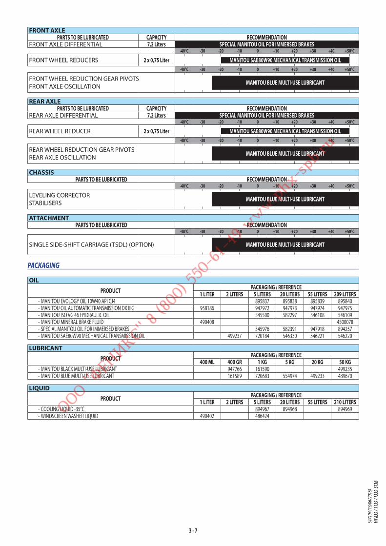
3 - 7
FRONT AXLEPARTS TO BE LUBRICATED CAPACITY RECOMMENDATION
FRONT AXLE DIFFERENTIAL 7,2 Liters SPECIAL MANITOU OIL FOR IMMERSED BRAKES-40°C -30 -20 -10 0 +10 +20 +30 +40 +50°C
FRONT WHEEL REDUCERS 2 x 0,75 Liter MANITOU SAE80W90 MECHANICAL TRANSMISSION OIL-40°C -30 -20 -10 0 +10 +20 +30 +40 +50°C
FRONT WHEEL REDUCTION GEAR PIVOTS
FRONT AXLE OSCILLATIONMANITOU BLUE MULTI-USE LUBRICANT
REAR AXLEPARTS TO BE LUBRICATED CAPACITY RECOMMENDATION
REAR AXLE DIFFERENTIAL 7,2 Liters SPECIAL MANITOU OIL FOR IMMERSED BRAKES-40°C -30 -20 -10 0 +10 +20 +30 +40 +50°C
REAR WHEEL REDUCER 2 x 0,75 Liter MANITOU SAE80W90 MECHANICAL TRANSMISSION OIL-40°C -30 -20 -10 0 +10 +20 +30 +40 +50°C
REAR WHEEL REDUCTION GEAR PIVOTS
REAR AXLE OSCILLATIONMANITOU BLUE MULTI-USE LUBRICANT
CHASSISPARTS TO BE LUBRICATED RECOMMENDATION
-40°C -30 -20 -10 0 +10 +20 +30 +40 +50°C
LEVELING CORRECTOR
STABILISERSMANITOU BLUE MULTI-USE LUBRICANT
ATTACHMENTPARTS TO BE LUBRICATED RECOMMENDATION
-40°C -30 -20 -10 0 +10 +20 +30 +40 +50°C
SINGLE SIDE-SHIFT CARRIAGE (TSDL) (OPTION) MANITOU BLUE MULTI-USE LUBRICANT
PACKAGING
OIL
PRODUCT PACKAGING / REFERENCE1 LITER 2 LITERS 5 LITERS 20 LITERS 55 LITERS 209 LITERS
- MANITOU EVOLOGY OIL 10W40 API CJ4 895837 895838 895839 895840 - MANITOU OIL AUTOMATIC TRANSMISSION DX IIIG 958186 947972 947973 947974 947975 - MANITOU ISO VG 46 HYDRAULIC OIL 545500 582297 546108 546109 - MANITOU MINERAL BRAKE FLUID 490408 4500078 - SPECIAL MANITOU OIL FOR IMMERSED BRAKES 545976 582391 947918 894257 - MANITOU SAE80W90 MECHANICAL TRANSMISSION OIL 499237 720184 546330 546221 546220
LUBRICANT
PRODUCT PACKAGING / REFERENCE400 ML 400 GR 1 KG 5 KG 20 KG 50 KG
- MANITOU BLACK MULTI-USE LUBRICANT 947766 161590 499235 - MANITOU BLUE MULTI-USE LUBRICANT 161589 720683 554974 499233 489670
LIQUID
PRODUCT PACKAGING / REFERENCE1 LITER 2 LITERS 5 LITERS 20 LITERS 55 LITERS 210 LITERS
- COOLING LIQUID -35°C 894967 894968 894969 - WINDSCREEN WASHER LIQUID 490402 486424
6471
04 (1
3/06
/201
6)
MT 83
5 / 11
35 / 1
335
ST3B
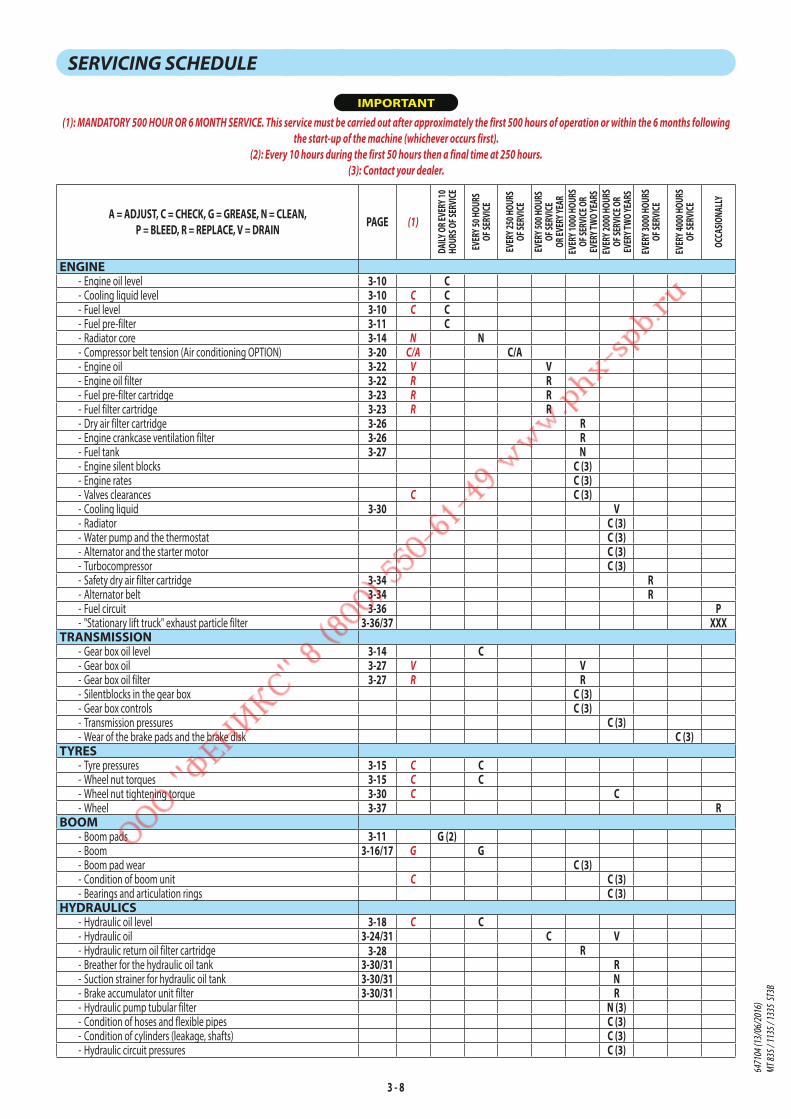
3 - 8
SERVICING SCHEDULE
IMPORTANT
(1): MANDATORY 500 HOUR OR 6 MONTH SERVICE. This service must be carried out after approximately the first 500 hours of operation or within the 6 months following
the start-up of the machine (whichever occurs first).
(2): Every 10 hours during the first 50 hours then a final time at 250 hours.
(3): Contact your dealer.
A = ADJUST, C = CHECK, G = GREASE, N = CLEAN, P = BLEED, R = REPLACE, V = DRAIN PAGE (1)
DAILY
OR E
VERY
10
HOUR
S OF S
ERVI
CE
EVER
Y 50 H
OURS
OF
SERV
ICE
EVER
Y 250
HOU
RS
OF SE
RVICE
EVER
Y 500
HOU
RS
OF SE
RVICE
OR
EVER
Y YEA
REV
ERY 1
000 H
OURS
OF
SERV
ICE O
R EV
ERY T
WO YE
ARS
EVER
Y 200
0 HOU
RS
OF SE
RVICE
OR
EVER
Y TWO
YEAR
S
EVER
Y 300
0 HOU
RS
OF SE
RVICE
EVER
Y 400
0 HOU
RS
OF SE
RVICE
OCCA
SIONA
LLY
ENGINE - Engine oil level 3-10 C - Cooling liquid level 3-10 C C - Fuel level 3-10 C C - Fuel pre-filter 3-11 C - Radiator core 3-14 N N - Compressor belt tension (Air conditioning OPTION) 3-20 C/A C/A - Engine oil 3-22 V V - Engine oil filter 3-22 R R - Fuel pre-filter cartridge 3-23 R R - Fuel filter cartridge 3-23 R R - Dry air filter cartridge 3-26 R - Engine crankcase ventilation filter 3-26 R - Fuel tank 3-27 N - Engine silent blocks C (3) - Engine rates C (3) - Valves clearances C C (3) - Cooling liquid 3-30 V - Radiator C (3) - Water pump and the thermostat C (3) - Alternator and the starter motor C (3) - Turbocompressor C (3) - Safety dry air filter cartridge 3-34 R - Alternator belt 3-34 R - Fuel circuit 3-36 P - "Stationary lift truck" exhaust particle filter 3-36/37 XXX
TRANSMISSION - Gear box oil level 3-14 C - Gear box oil 3-27 V V - Gear box oil filter 3-27 R R - Silentblocks in the gear box C (3) - Gear box controls C (3) - Transmission pressures C (3) - Wear of the brake pads and the brake disk C (3)
TYRES - Tyre pressures 3-15 C C - Wheel nut torques 3-15 C C - Wheel nut tightening torque 3-30 C C - Wheel 3-37 R
BOOM - Boom pads 3-11 G (2) - Boom 3-16/17 G G - Boom pad wear C (3) - Condition of boom unit C C (3) - Bearings and articulation rings C (3)
HYDRAULICS - Hydraulic oil level 3-18 C C - Hydraulic oil 3-24/31 C V - Hydraulic return oil filter cartridge 3-28 R - Breather for the hydraulic oil tank 3-30/31 R - Suction strainer for hydraulic oil tank 3-30/31 N - Brake accumulator unit filter 3-30/31 R - Hydraulic pump tubular filter N (3) - Condition of hoses and flexible pipes C (3) - Condition of cylinders (leakage, shafts) C (3) - Hydraulic circuit pressures C (3)
6471
04 (1
3/06
/201
6)
MT 83
5 / 11
35 / 1
335
ST3B

3 - 9
A = ADJUST, C = CHECK, G = GREASE, N = CLEAN, P = BLEED, R = REPLACE, V = DRAIN PAGE (1)
DAILY
OR E
VERY
10
HOUR
S OF S
ERVI
CE
EVER
Y 50 H
OURS
OF
SERV
ICE
EVER
Y 250
HOU
RS
OF SE
RVICE
EVER
Y 500
HOU
RS
OF SE
RVICE
OR
EVER
Y YEA
REV
ERY 1
000 H
OURS
OF
SERV
ICE O
R EV
ERY T
WO YE
ARS
EVER
Y 200
0 HOU
RS
OF SE
RVICE
OR
EVER
Y TWO
YEAR
S
EVER
Y 300
0 HOU
RS
OF SE
RVICE
EVER
Y 400
0 HOU
RS
OF SE
RVICE
OCCA
SIONA
LLY
BRAKE - Brake oil level 3-18 C C - Brake oil V (3) - Brake system P (3) - Brake system pressure C (3) - Brake A (3)
STEERING - Steering C (3) - Steering swivel joints C (3)
CAB - Windscreen washer liquid level 3-19 C C - Cab ventilation filters 3-19/20 R N R - Condenser core (Air conditioning OPTION) 3-19 C/N C/N - Seat belt 3-29 C - Condition of the rear view mirrors C (3) - Structure C (3) - Air conditioning (OPTION) 3-32 N/C
ELECTRICITY - Longitudinal stability limiter and warning device 3-12/38 C C XXX - Condition of wiring harness and cables C (3) - Lights and signals C (3) - Warning indicators C (3) - Front headlights 3-39 A - Battery failure 3-39 R
FRONT AXLE - Front wheel reduction gear pivots 3-18/19 G G G/C (3) - Front axle oscillation MT 1135 ST3B / MT 1335 ST3B 3-18/19 G G G/C (3) - Front axle differential oil level 3-21 C - Front wheels reduction gear oil level 3-21 C - Front axle differential oil 3-24 V V - Front wheel reduction gear oil 3-29 V V - Wear of front axle brake discs C (3) - Front wheel reduction gear universal joint C (3) - Front wheel reduction gear clearance C (3)
REAR AXLE - Rear wheel reduction gear pivots 3-18/19 G G G/C (3) - Rear axle oscillation 3-18/19 G G G/C (3) - Rear axle differential oil level 3-21 C - Rear wheel reduction gear oil level 3-21 C - Rear axle differential oil 3-24 V V - Rear wheel reduction gear oil 3-29 V V - Wearing of rear axle brake discs C (3) - Rear wheel reduction gear universal joint C (3) - Rear wheels reduction gear clearance C (3)
CHASSIS - Tilting corrector MT 1135 ST3B / MT 1335 ST3B 3-18/19 G G - Stabilisers MT 1135 ST3B / MT 1335 ST3B 3-18/19 G G - Structure C (3) - Bearings and articulation rings C (3)
ATTACHMENTS - Single side-shift carriage (TSDL) (OPTION) 3-18/19 G G - Forks wear C C (3) - Attachment carriage C (3) - Condition of attachments C (3)
LIFT TRUCK - Tow the lift truck 3-40 XXX - Sling the lift truck 3-40 XXX - Transport the lift truck on a platform 3-41 XXX
6471
04 (1
3/06
/201
6)
MT 83
5 / 11
35 / 1
335
ST3B
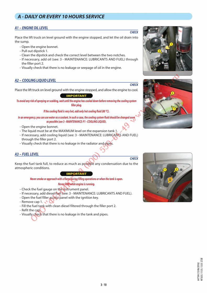
3 - 10
A - DAILY OR EVERY 10 HOURS SERVICE
A1 – ENGINE OIL LEVELCHECK
Place the lift truck on level ground with the engine stopped, and let the oil drain into
the sump.
- Open the engine bonnet.
- Pull out dipstick 1.
- Clean the dipstick and check the correct level between the two notches.
- If necessary, add oil (see: 3 - MAINTENANCE: LUBRICANTS AND FUEL) through
the filler port 2.
- Visually check that there is no leakage or seepage of oil in the engine.
A2 – COOLING LIQUID LEVELCHECK
Place the lift truck on level ground with the engine stopped, and allow the engine to cool.
IMPORTANT
To avoid any risk of spraying or scalding, wait until the engine has cooled down before removing the cooling system
filler plug.
If the cooling fluid is very hot, add only hot cooling fluid (80 °C).
In an emergency, you can use water as a coolant. In such a case, the cooling system fluid should be changed soon
as possible (see 3 - MAINTENANCE: F1 - COOLING LIQUID).
- Open the engine bonnet.
- The liquid must be at the MAXIMUM level on the expansion tank 1.
- If necessary, add cooling liquid (see: 3 - MAINTENANCE: LUBRICANTS AND FUEL)
through the filler port 2.
- Visually check that there is no leakage in the radiator and pipes.
A3 – FUEL LEVELCHECK
Keep the fuel tank full, to reduce as much as possible any condensation due to the
atmospheric conditions.
IMPORTANT
Never smoke or approach with a flame during filling operations or when the tank is open.
Never refill while engine is running.
- Check the fuel gauge on the instrument panel.
- If necessary, add diesel fuel (see: 3 - MAINTENANCE: LUBRICANTS AND FUEL).
- Open the fuel filler access panel with the ignition key.
- Remove cap 1.
- Fill the fuel tank with clean diesel filtered through the filler port 2.
- Refit the cap.
- Visually check that there is no leakage in the tank and pipes.
1
2
1 2
1
2
6471
04 (1
3/06
/201
6)
MT 83
5 / 11
35 / 1
335
ST3B

3 - 11
A4 – FUEL PRE-FILTERCHECK
IMPORTANT
Carefully clean the outside of the pre-filter and its holder, to prevent dust from getting into the system.
- Open the engine bonnet.
- Check for the presence of water in pre-filter tank 1 and drain if necessary.
- Place a receptacle under the drain plug 2 and loosen by two to three turns.
- Open bleed screw 3.
- Allow the diesel fuel to flow out until it is free from impurities and water.
- Retighten drain plug 2 and bleed screw 3.
A5 – BOOM PADSCLEAN - GREASE
To be carried out every 10 hours during the first 50 hours service,
then once at 250 hours.
IMPORTANT
If the lift truck is used in an abrasive environment (dust, sand, coal, etc.) use lubricating
varnish (MANITOU reference: 483536).
Consult your dealer for this varnish.
- Fully extend the boom.
- Apply the grease with a brush (see: 3 - MAINTENANCE:
LUBRICANTS AND FUEL) to the 4 sides of the telescope(s).
- Telescope the boom several times in order to spread the coat
of grease evenly.
- Remove the surplus of grease.
1
2
3
6471
04 (1
3/06
/201
6)
MT 83
5 / 11
35 / 1
335
ST3B

3 - 12
A6 – LONGITUDINAL STABILITY LIMITER AND WARNING DEVICECHECK
IMPORTANT
In case of doubt during the test procedure, exit by briefly pressing the cancel button .
The appearance of the
GAUGE
C a l i b r a t i o ni n c o m p l e t e d
o r f a i l e d screen indicates a failure to obey an instruction, a cancellation request or a late response.
If in doubt, consult your dealer.
- These tests are essential for checking the correct operation and adjustment of the different components of the device.
- Place the lift truck on flat, level ground with the wheels straight.
- Hold down the test button .
STAGE 1 TEST
P r e s s t o E n t e r
S e c u r i t y T e s t M o d e
Start of procedure.
Validate Go to stage 2.
STAGE 2 TEST
F u l l y e x t e n t e dt h e s t a b i l i z e r s
t h e n p r e s s
Place the lift truck with no attachments, set down the left
and right stabilisers, if provided, with the front wheels off the
ground.
Validate
Go to stage 3.
STAGE 3 TEST
R e t r a c t t e l e s c o p eL i f t t h e b o o m t o
m a x p o s i t i o nt h e n p r e s s
Raise the boom and retract the telescopes completely.
Validate
TEST
R e t r a c t T e l e s c o p e O KB o o m S e n s o r N O KS t r a i n G a u g e N O K
TEST OKGo to stage 4.
TEST NON OKValidate or cancel .
Consult your dealer.
STAGE 4 TEST
L o w e r t h e b o o m
a t f u l l s p e e d
Lower the boom with the engine running at full revs and the
hydraulic control at the maximum setting. Lowering slows
until movement is cut-off.
TEST
R e g u l a t i o n N O K
S e c u r i t y V a l v e O K
TEST OKGo to stage 5.
TEST NON OKValidate or cancel .
Consult your dealer.
STAGE 5 TEST
L o w e r t h e b o o m
u n t i l s t o p Continue to lower the boom with the engine running at
full revs and the hydraulic control at the maximum setting.
Lowering slows until movement is next cut-off.
TEST
S e c u r i t y V a l v e N O K
TEST OKGo to stage 6.
TEST NON OKValidate or cancel .
Consult your dealer.
STAGE 6 TEST
T e s t m o v e m e n t st h e n i f t e s t O K :
o r t e s t N O K :
Try in the following order a reverse tilt, a forward tilt and a
telescope extension.
None of these 3 movements should be possible.
TEST OKValidate .
TEST NON OKCancel .
Consult your dealer.
STAGE 7TEST
Security Test
Procedure OKEnd of procedure.
6471
04 (1
3/06
/201
6)
MT 83
5 / 11
35 / 1
335
ST3B

3 - 13
6471
04 (1
3/06
/201
6)
MT 83
5 / 11
35 / 1
335
ST3B
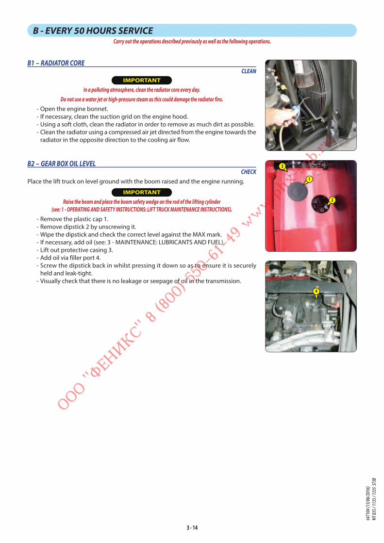
3 - 14
B - EVERY 50 HOURS SERVICECarry out the operations described previously as well as the following operations.
B1 – RADIATOR CORECLEAN
IMPORTANT
In a polluting atmosphere, clean the radiator core every day.
Do not use a water jet or high-pressure steam as this could damage the radiator fins.
- Open the engine bonnet.
- If necessary, clean the suction grid on the engine hood.
- Using a soft cloth, clean the radiator in order to remove as much dirt as possible.
- Clean the radiator using a compressed air jet directed from the engine towards the
radiator in the opposite direction to the cooling air flow.
4
1
2
3B2 – GEAR BOX OIL LEVELCHECK
Place the lift truck on level ground with the boom raised and the engine running.
IMPORTANT
Raise the boom and place the boom safety wedge on the rod of the lifting cylinder
(see: 1 - OPERATING AND SAFETY INSTRUCTIONS: LIFT TRUCK MAINTENANCE INSTRUCTIONS).
- Remove the plastic cap 1.
- Remove dipstick 2 by unscrewing it.
- Wipe the dipstick and check the correct level against the MAX mark.
- If necessary, add oil (see: 3 - MAINTENANCE: LUBRICANTS AND FUEL).
- Lift out protective casing 3.
- Add oil via filler port 4.
- Screw the dipstick back in whilst pressing it down so as to ensure it is securely
held and leak-tight.
- Visually check that there is no leakage or seepage of oil in the transmission.
6471
04 (1
3/06
/201
6)
MT 83
5 / 11
35 / 1
335
ST3B
3 - 15
B3 – TYRE PRESSURE AND WHEEL NUT TORQUESCHECK
IMPORTANT
Check that the air hose is correctly connected to the tyre valve before inflating and keep all persons at a distance during inflation. Respect the recommended
tyre pressures given.
- Check the condition of the tyres, to detect cuts, protuberances, wear, etc.
- Check the torque load of the wheel nuts. Non-compliance with this instruction can cause damage and rupture to the
wheel bolts and distortion to the wheels.
- Check and restore tyre pressures if necessary (see: 2 - DESCRIPTION: TYRES).
NOTE: There is an OPTIONAL wheel toolkit.
6471
04 (1
3/06
/201
6)
MT 83
5 / 11
35 / 1
335
ST3B

3 - 16
B4 – GENERAL GREASINGGREASE
To be carried out weekly, if the lift truck has been operated for less than 50 hours during the week.
IMPORTANT
In the event of prolonged use in an extremely dusty or oxidising atmosphere, reduce this interval to 10 working hours or every day.
Clean and lubricate the following points with grease (see: 3 - MAINTENANCE: LUBRICANTS AND FUEL) and remove the surplus
of grease.
BOOM1 - Lubricators of the boom axle (2 lubricators).
2 - Lubricators of the carriage axle (2 lubricators).
3 - Lubricator of the tilt cylinder foot axle (1 lubricator).
4 - Lubricator of the tilt cylinder head axle (1 lubricator).
5 - Lubricator of the lifting cylinder foot axle (1 lubricator).
6 - Lubricator of the lifting cylinder head axle (1 lubricator).
7 - Lubricator of the compensation cylinder foot axle (1 lubricator).
8 - Lubricator of the compensation cylinder head axle (1 lubricator).
FRONT AND REAR WHEEL REDUCTION GEAR PIVOTS9 - Lubricators of the wheel reduction gear pivot pins (8 lubricators).
AXLE OSCILLATION10 - Front axle oscillation lubricators (2 lubricators). MT 1135 ST3B / MT 1335 ST3B11 - Rear axle oscillation lubricators (2 lubricators).
ROLL CORRECTORMT 1135 ST3B / MT 1335 ST3B
12 - Lubricator of the roll corrector cylinder foot axle (2 lubricators).
13 - Lubricator of the roll corrector cylinder head axle (1 lubricator).
STABILIZERSMT 1135 ST3B / MT 1335 ST3B
14 - Lubricators of the stabiliser cylinders’ foot axle (2 lubricators).
15 - Lubricators of the stabiliser cylinders’ head axle (2 lubricators).
16 - Lubricators of the stabiliser axles (4 lubricators).
SINGLE SIDE-SHIFT CARRIAGE (TSDL) (OPTION)17 - Wear plate lubricators (8 lubricators).
6471
04 (1
3/06
/201
6)
MT 83
5 / 11
35 / 1
335
ST3B
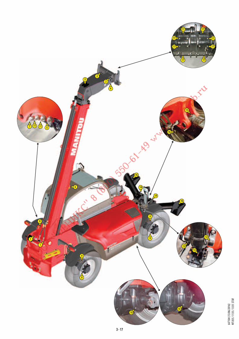
3 - 17
17
17
17
17
17 17
17 17
1
1
9
98
6
3
4
2
2
14
16
16
14
1010
16
15
11 11
12
1312
9
9
7 5
6471
04 (1
3/06
/201
6)
MT 83
5 / 11
35 / 1
335
ST3B

3 - 18
B5 – HYDRAULIC OIL LEVELCHECK
Place the lift truck on level ground with the I.C. engine stopped, and the jib retracted
and lowered as far as possible.
IMPORTANT
Use a clean funnel and clean the underside of the oil drum before filling.
- Check the level on the low level gauge 1. The level is correct when it is situated
above the level of the red point.
- If necessary, add oil (see: 3 - MAINTENANCE: LUBRICANTS AND FUEL).
- Open the hydraulic oil filler access panel with the ignition key.
- Remove the filler cap lock 2.
- Remove cap 3.
- Add oil through filler port 4 up to the black dot on the high level gauge 5.
- Refit the cap and its lock.
- Visually check that there is no leakage in the tank and pipes.
B6 – BRAKE OIL LEVELCHECK
Place the lift truck on level ground.
IMPORTANT
If the braking oil level is abnormally low, consult your dealer.
- Open the protective casing 1 with the ignition key.
- Check tank 2. The level is correct when it is situated at the MAX level on the tank.
- If necessary, add oil (see: 3 - MAINTENANCE: LUBRICANTS AND FUEL).
- Remove cap 3.
- Add oil through filler port 4.
- Refit the cap.
- Visually check that there is no leakage in the tank and pipes.
1
2
3
4
5
1
4
3
2
6471
04 (1
3/06
/201
6)
MT 83
5 / 11
35 / 1
335
ST3B

3 - 19
B7 – WINDSCREEN WASHER LIQUID LEVELCHECK
- Visually check the level in tank 1.
- If necessary add windscreen washer liquid (see: 3 - MAINTENANCE: LUBRICANTS
AND FUEL).
- Remove cap 2.
- Add windscreen washer liquid through filler port 3.
- Refit the cap.
B8 – CAB VENTILATION FILTERSCLEAN
EXTERNAL CAB VENTILATION FILTER - Lift out cab ventilation filter 1.
- Clean the filter with a compressed air jet.
- Check its condition and change if necessary
(see: 3 - MAINTENANCE: FILTERS CARTRIDGES
AND BELTS).
- Reinstall the filter.
- Refit the protective casing 2.
INTERNAL CAB VENTILATION FILTER - Remove the protective grid 3.
- Lift out cab ventilation filter 4
- Clean the filter with a compressed air jet.
- Check its condition and change if necessary
(see: 3 - MAINTENANCE: FILTERS CARTRIDGES
AND BELTS).
- Reinstall the filter.
- Refit the protective grid 3.
B9 – CONDENSER CORE (OPTION AIR CONDITIONING)CHECK - CLEAN
IMPORTANT
In a polluting atmosphere, clean the radiator core every day.
Do not use a water jet or high-pressure steam as this could damage the condenser fins.
- Visually check whether the condenser is clean and clean it if necessary.
- Clean the condenser using a compressed air jet aimed in the same direction as
the air flow.
- Clean with the fans running for best results.
1
23
1
2
34
6471
04 (1
3/06
/201
6)
MT 83
5 / 11
35 / 1
335
ST3B

3 - 20
C - EVERY 250 HOURS OF SERVICECarry out the operations described previously as well as the following operations.
C1 – COMPRESSOR BELT TENSION (OPTION AIR CONDITIONING)CHECK - ADJUST
IMPORTANT
If the compressor belt has to be changed, check the tension again after the first 20 hours of operation.
- Open engine bonnet and the lower cover.
- Unscrew the fastening screws 1.
- Remove the protective casing 2.
- Check the belt for signs of wear and cracks and change if necessary (see: 3 -
MAINTENANCE: FILTERS CARTRIDGES AND BELTS).
- Check the belt tension between the pulleys of the crankshaft and of the compressor.
- Under a normal pressure exerted with the thumb (45 N), the belt should move
approximately 10 mm.
- Adjust if necessary.
- Loosen the screws 3 by two to three turns.
- Swivel the compressor assembly so as to obtain the belt tension required.
- Retighten screws 3 (tightening torque 22 N.m).
C2 – CAB VENTILATION FILTERSCHANGE
EXTERNAL CAB VENTILATION FILTER - Remove protective casing 1 using the ignition
key.
- Lift out cab ventilation filter 2 and replace
it with a new one (see: 3 - MAINTENANCE:
FILTERS, CARTRIDGES AND BELTS).
- Refit the protective casing.
INTERNAL CAB VENTILATION FILTER - Remove the protective grid 3.
- Lift out cab ventilation filter 4 and replace
it with a new one (see: 3 - MAINTENANCE:
FILTERS, CARTRIDGES AND BELTS).
- Refit the protective grid.
2
1
34
1 1
1
1
2
3
3
3
6471
04 (1
3/06
/201
6)
MT 83
5 / 11
35 / 1
335
ST3B

3 - 21
C3 – FRONT AND REAR AXLE DIFFERENTIAL OIL LEVELCHECK
Place the lift truck on level ground with the engine stopped.
- Remove the level plug 1; the oil should be flush with the edge of the hole.
- If necessary, add oil (see: 3 - MAINTENANCE: LUBRICANTS AND FUEL) through the
filler port 2.
- Refit and tighten the level plug 1 (tightening torque 34 to 49 N.m).
C4 – FRONT AND REAR WHEEL REDUCTION GEAR OIL LEVELCHECK
Place the lift truck on level ground with the engine stopped.
- Check the level on each wheel reduction gear.
- Place level plug 1 in a horizontal position.
- Remove the level plug; the oil should be flush with the edge of the opening.
- If necessary, add oil (see: 3 - MAINTENANCE: LUBRICANTS AND FUEL) through the
same opening.
- Refit and tighten the level plug (tightening torque 34 to 49 N.m).
1
2
1
6471
04 (1
3/06
/201
6)
MT 83
5 / 11
35 / 1
335
ST3B

3 - 22
D - EVERY 500 HOURS OF SERVICE OR EVERY YEARCarry out the operations described previously as well as the following operations.
A maintenance warning is displayed at 480 hours on the help screen followed by a 20 hour countdown to reach
the 500 hour maintenance deadline. After this period, the help screen is displayed , followed by the maintenance
key . The maintenance then has to be performed.
NOTE: Once this maintenance has been conducted (D - EVERY 500 HOURS OF SERVICE), reset the maintenance counter
to 500 hours from the “XPRT > RESET > MAINT“ menu in the menu screen.
D1 – ENGINE OILDRAIN
D2 – ENGINE OIL FILTERCHANGE
Place the lift truck on level ground, let the engine run at idle for a few minutes, then
stop the engine.
IMPORTANT
USE THE RECOMMENDED LUBRICANTS: Oil MANITOU GOLD "API CJ-4 ; ACEA E9"
Dispose of the drain oil in an ecological manner.
DRAINING THE OIL - Open engine bonnet and the lower cover.
- Remove access panel 1.
- Place a container under drain plug 2 and unscrew the plug.
- Take drain hose 3.
- Place the end of the drain hose in the container and screw the hose fully to the
drain connector 2.
- Remove level and filling plug 4 to ensure that the oil is drained properly.
REPLACEMENT OF THE FILTER - Unscrew and discard the engine oil filter 5, together with its seal.
- Clean the filter bracket with a clean, lint-free cloth.
- Lightly grease the new seal before refitting the new oil filter (see: 3 - MAINTENANCE:
FILTERS, CARTRIDGES AND BELTS) on its bracket.
- Tighten the oil filter (tightening torque 30 N.m).
FILLING UP THE OIL - Remove, clean and refit drain hose 3.
- Replace and tighten the drain plug 2.
- Fill up with oil (see: 3 - MAINTENANCE: LUBRICANTS AND FUEL) through filler port 4.
- Wait a few minutes to allow the oil to flow into the sump.
- Start the engine and let it run for a few minutes.
- Check for possible leaks from the drain plug and the oil filter.
- Stop the engine, wait a few minutes and check the correct level between the two
level marks on the dipstick 6.
- Top up the level if necessary.
- Refit access panel 1.
NOTE: If the help screen is displayed before the 500 hour maintenance,
replace the engine oil. This is due to a large number of automatic exhaust
particle filter regenerations and “stationary lift truck“ exhaust particle filter
regenerations.
After replacing the oil, delete the help screen from the “XPRT >
RESET > OIL“ menu in the menu screen. 4
6
1
3
2
5
6471
04 (1
3/06
/201
6)
MT 83
5 / 11
35 / 1
335
ST3B

3 - 23
D3 – FUEL PRE-FILTER CARTRIDGECHANGE
IMPORTANT
Carefully clean the outside of the pre-filter and its holder, to prevent dust from getting into the system.
- Open the engine bonnet.
- Scribe a mark A between the head and the housing of the pre-filter.
- Place a receptacle under the drain plug 1 and loosen it by two to three turns.
- Open bleed screw 2 to ensure proper emptying.
- Retighten bleed screw 2 once the pre-filter is emptied.
- Disconnect electrical wiring harness 3 from the fuel pre-filter.
- Unscrew the body of the pre-filter 4.
- Remove cartridge 5 by unscrewing it and discard it together with its seal.
- Clean the inside of the pre-filter head and housing using a brush immersed in
clean diesel oil.
- Refit the assembly with a new cartridge and a new seal lubricated with clean engine
oil beforehand (see: 3 - MAINTENANCE: FILTERS CARTRIDGES AND BELTS).
- Correctly position the cartridge in the pre-filter housing and screw the assembly
by hand only onto the head of the pre-filter until mark A is aligned.
- Replace the fuel filter cartridge.
D4 – FUEL FILTER CARTRIDGECHANGE
IMPORTANT
Carefully clean the outside of the filter and its holder, to prevent dust from getting into the system.
- Open the engine bonnet.
- Scribe a mark A between the head and the housing of the filter.
- Place a receptacle under the drain plug 1 and loosen it by two to three turns.
- Open bleed screw 2 to ensure proper emptying.
- Retighten bleed screw 2 once the filter is emptied.
- Undo the filter housing 3.
- Remove cartridge 4 by unscrewing it and discard it together with its seal.
- Clean the inside of the filter head and housing using a brush immersed in clean
diesel oil.
- Refit the assembly with a new cartridge and a new seal lubricated with clean engine
oil beforehand (see: 3 - MAINTENANCE: FILTERS CARTRIDGES AND BELTS).
- Correctly position the cartridge in the filter housing and screw the assembly by
hand only onto the head of the pre-filter until mark A is aligned.
- Bleed the fuel circuit (see: 3 - MAINTENANCE: H1 - FUEL SYSTEM).
A
1
2
3
4
5
1
3
A
2
4
6471
04 (1
3/06
/201
6)
MT 83
5 / 11
35 / 1
335
ST3B

3 - 24
D6 – FRONT AND REAR AXLE DIFFERENTIAL OILDRAIN
Place the lift truck on level ground with the engine stopped and the differential oil still warm.
IMPORTANT
Dispose of the drain oil in an ecological manner.
- Place a container under the drain plugs 1 and unscrew them.
- Remove level plug 2 and filling plug 3 to ensure that the oil is drained properly.
- Refit and tighten the drain plugs 1 (tightening torque 34 to 49 N.m).
- Fill up with oil (see: 3 - MAINTENANCE: LUBRICANTS AND FUEL) through filler port 3.
- The level is correct when the oil level is flush with the edge of opening 2.
- Check for any possible leaks at the drain plugs.
- Refit and tighten level plug 2 (tightening torque 34 to 49 N.m) and filler plug 3
(tightening torque 34 to 49 N.m).
- Repeat this operation for the rear axle differential.
D5 – HYDRAULIC OILCHECK
MANITOU recommends analyzing the hydraulic oil after the first 500 hours of lift truck
operation. Following that, MANITOU requests that the oil is analyzed every 500 hours
of operation. The results will determine whether or not the hydraulic oil is changed
(contact your dealer).
MANITOU oil analysis kit Part No. 958162.
1 11
2
3
6471
04 (1
3/06
/201
6)
MT 83
5 / 11
35 / 1
335
ST3B

3 - 25
6471
04 (1
3/06
/201
6)
MT 83
5 / 11
35 / 1
335
ST3B
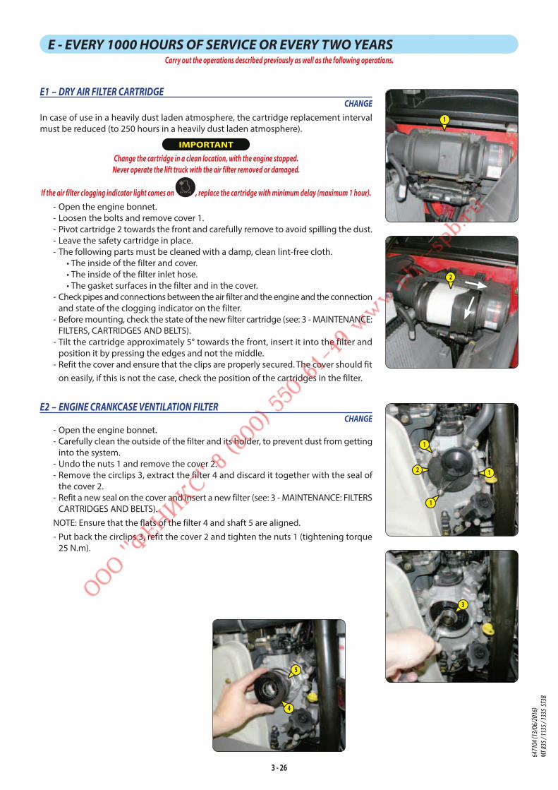
3 - 26
E - EVERY 1000 HOURS OF SERVICE OR EVERY TWO YEARSCarry out the operations described previously as well as the following operations.
E1 – DRY AIR FILTER CARTRIDGECHANGE
In case of use in a heavily dust laden atmosphere, the cartridge replacement interval
must be reduced (to 250 hours in a heavily dust laden atmosphere).
IMPORTANT
Change the cartridge in a clean location, with the engine stopped.
Never operate the lift truck with the air filter removed or damaged.
If the air filter clogging indicator light comes on , replace the cartridge with minimum delay (maximum 1 hour).
- Open the engine bonnet.
- Loosen the bolts and remove cover 1.
- Pivot cartridge 2 towards the front and carefully remove to avoid spilling the dust.
- Leave the safety cartridge in place.
- The following parts must be cleaned with a damp, clean lint-free cloth.
• The inside of the filter and cover.
• The inside of the filter inlet hose.
• The gasket surfaces in the filter and in the cover.
- Check pipes and connections between the air filter and the engine and the connection
and state of the clogging indicator on the filter.
- Before mounting, check the state of the new filter cartridge (see: 3 - MAINTENANCE:
FILTERS, CARTRIDGES AND BELTS).
- Tilt the cartridge approximately 5° towards the front, insert it into the filter and
position it by pressing the edges and not the middle.
- Refit the cover and ensure that the clips are properly secured. The cover should fit
on easily, if this is not the case, check the position of the cartridges in the filter.
E2 – ENGINE CRANKCASE VENTILATION FILTERCHANGE
- Open the engine bonnet.
- Carefully clean the outside of the filter and its holder, to prevent dust from getting
into the system.
- Undo the nuts 1 and remove the cover 2.
- Remove the circlips 3, extract the filter 4 and discard it together with the seal of
the cover 2.
- Refit a new seal on the cover and insert a new filter (see: 3 - MAINTENANCE: FILTERS
CARTRIDGES AND BELTS).
NOTE: Ensure that the flats of the filter 4 and shaft 5 are aligned.
- Put back the circlips 3, refit the cover 2 and tighten the nuts 1 (tightening torque
25 N.m).
1
1
1
2
3
4
5
1
2
6471
04 (1
3/06
/201
6)
MT 83
5 / 11
35 / 1
335
ST3B

3 - 27
E3 – FUEL TANKCLEAN
Place the lift truck on level ground with the engine stopped.
IMPORTANT
While carrying out these operations, do not smoke or work near a flame.
Never try to carry out a weld or any other operation by yourself, this could provoke an explosion or a fire.
- Inspect the parts susceptible to leaks in the fuel circuit and in the tank both visually
and by touch.
- In the event of a leak, contact your dealer.
- Place a container under drain plug 1 and unscrew the plug.
- Open the fuel filler access panel with the ignition key.
- Remove filling plug 2 to ensure that the oil is drained properly.
- Rinse out with ten litres of clean diesel through filler port 3.
- Refit and tighten the drain plug (tightening torque 29 to 39 N.m).
- Fill the fuel tank with clean diesel filtered through the filler port.
- Refit the filler plug.
- If necessary, bleed the fuel supply system (see: 3 - MAINTENANCE: H1 - FUEL SYSTEM).
1
2 3
3
5
1
2
4
E4 – GEAR BOX OILDRAIN
E5 – GEAR BOX OIL FILTERCHANGE
Place the lift truck on level ground with the engine stopped, the gear box oil still warm.
IMPORTANT
Raise the boom and place the boom safety wedge on the rod of the lifting cylinder
(see: 1 - OPERATING AND SAFETY INSTRUCTIONS: LIFT TRUCK MAINTENANCE INSTRUCTIONS).
Dispose of the drain oil in an ecological manner.
Tighten the oil filter by hand pressure only and lock the filter in place by a quarter turn.
DRAINING THE OIL - Remove cover plate 1.
- Place a container under drain plug 2 and unscrew the plug.
- Remove dipstick 3 to ensure proper emptying.
REPLACEMENT OF THE FILTER - Unscrew and discard gear box oil filter 4, together with its seal.
- Clean the filter bracket with a clean, lint-free cloth.
- Lightly grease the new seal before refitting the new oil filter (see: 3 - MAINTENANCE:
FILTERS, CARTRIDGES AND BELTS) on its bracket.
FILLING UP THE OIL - Refit and tighten the drain plug 2 (tightening torque 34 to 54 N.m).
- Unscrew the filler cap 5, and fill up with oil (see: 3 - MAINTENANCE: LUBRICANTS
AND FUEL) through the port, and refit the filler cap 5.
- Start the engine and leave it at idle.
- Check for possible leaks from the drain plug
and the oil filter.
- Check the correct level against the MAX mark
on the dipstick 3.
- Top up the level if necessary.
- Refit cover plate 1.
6471
04 (1
3/06
/201
6)
MT 83
5 / 11
35 / 1
335
ST3B
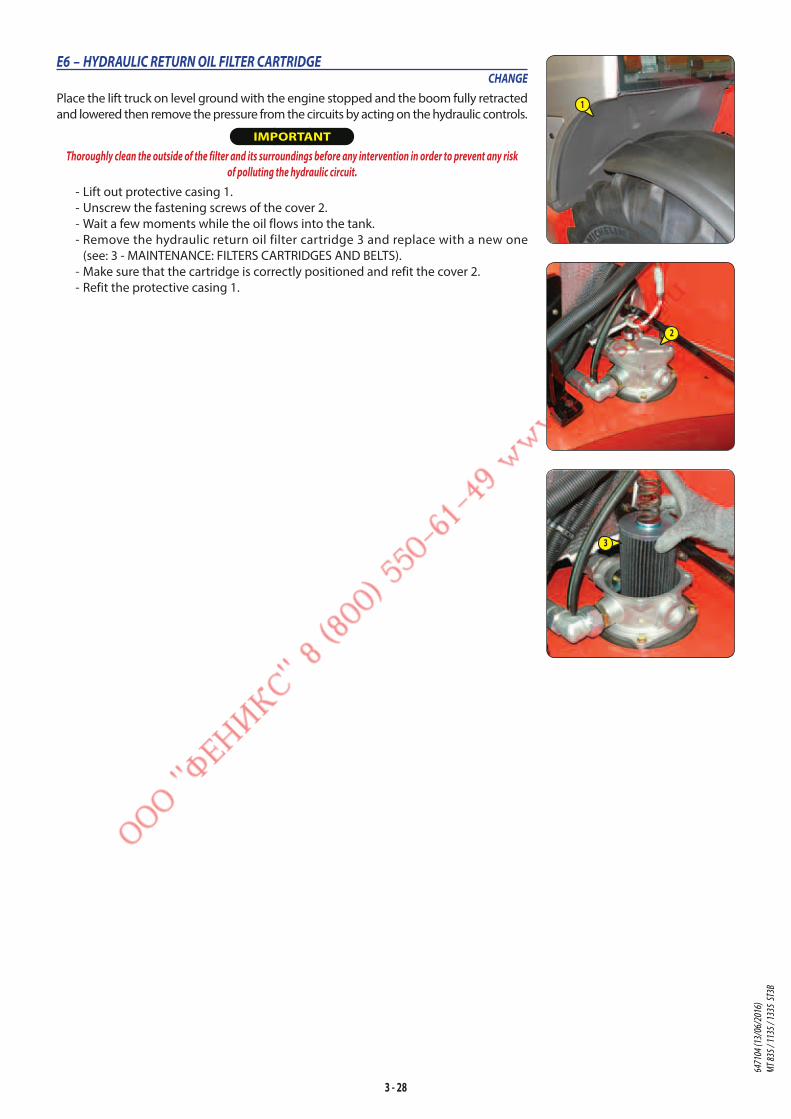
3 - 28
E6 – HYDRAULIC RETURN OIL FILTER CARTRIDGECHANGE
Place the lift truck on level ground with the engine stopped and the boom fully retracted
and lowered then remove the pressure from the circuits by acting on the hydraulic controls.
IMPORTANT
Thoroughly clean the outside of the filter and its surroundings before any intervention in order to prevent any risk
of polluting the hydraulic circuit.
- Lift out protective casing 1.
- Unscrew the fastening screws of the cover 2.
- Wait a few moments while the oil flows into the tank.
- Remove the hydraulic return oil filter cartridge 3 and replace with a new one
(see: 3 - MAINTENANCE: FILTERS CARTRIDGES AND BELTS).
- Make sure that the cartridge is correctly positioned and refit the cover 2.
- Refit the protective casing 1.
2
1
3
6471
04 (1
3/06
/201
6)
MT 83
5 / 11
35 / 1
335
ST3B
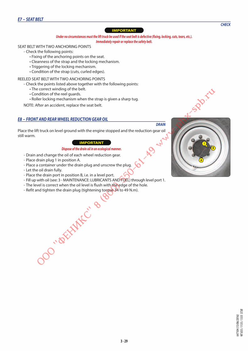
3 - 29
E7 – SEAT BELTCHECK
IMPORTANT
Under no circumstances must the lift truck be used if the seat belt is defective (fixing, locking, cuts, tears, etc.).
Immediately repair or replace the safety belt.
SEAT BELT WITH TWO ANCHORING POINTS
- Check the following points:
• Fixing of the anchoring points on the seat.
• Cleanness of the strap and the locking mechanism.
• Triggering of the locking mechanism.
• Condition of the strap (cuts, curled edges).
REELED SEAT BELT WITH TWO ANCHORING POINTS
- Check the points listed above together with the following points:
• The correct winding of the belt.
• Condition of the reel guards.
• Roller locking mechanism when the strap is given a sharp tug.
NOTE: After an accident, replace the seat belt.
E8 – FRONT AND REAR WHEEL REDUCTION GEAR OILDRAIN
Place the lift truck on level ground with the engine stopped and the reduction gear oil
still warm.
IMPORTANT
Dispose of the drain oil in an ecological manner.
- Drain and change the oil of each wheel reduction gear.
- Place drain plug 1 in position A.
- Place a container under the drain plug and unscrew the plug.
- Let the oil drain fully.
- Place the drain port in position B, i.e. in a level port.
- Fill up with oil (see: 3 - MAINTENANCE: LUBRICANTS AND FUEL) through level port 1.
- The level is correct when the oil level is flush with the edge of the hole.
- Refit and tighten the drain plug (tightening torque 34 to 49 N.m).
1B
A
6471
04 (1
3/06
/201
6)
MT 83
5 / 11
35 / 1
335
ST3B
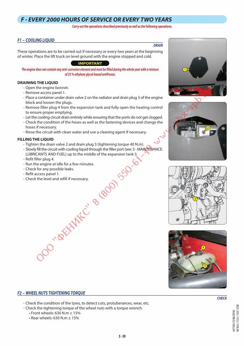
3 - 30
F - EVERY 2000 HOURS OF SERVICE OR EVERY TWO YEARSCarry out the operations described previously as well as the following operations.
F1 – COOLING LIQUIDDRAIN
These operations are to be carried out if necessary or every two years at the beginning
of winter. Place the lift truck on level ground with the engine stopped and cold.
IMPORTANT
The engine does not contain any anti-corrosion element and must be filled during the whole year with a mixture
of 25 % ethylene glycol-based antifreeze.
DRAINING THE LIQUID - Open the engine bonnet.
- Remove access panel 1.
- Place a container under drain valve 2 on the radiator and drain plug 3 of the engine
block and loosen the plugs.
- Remove filler plug 4 from the expansion tank and fully open the heating control
to ensure proper emptying.
- Let the cooling circuit drain entirely while ensuring that the ports do not get clogged.
- Check the condition of the hoses as well as the fastening devices and change the
hoses if necessary.
- Rinse the circuit with clean water and use a cleaning agent if necessary.
FILLING THE LIQUID - Tighten the drain valve 2 and drain plug 3 (tightening torque 40 N.m).
- Slowly fill the circuit with cooling liquid through the filler port (see: 3 - MAINTENANCE:
LUBRICANTS AND FUEL) up to the middle of the expansion tank 5.
- Refit filler plug 4.
- Run the engine at idle for a few minutes.
- Check for any possible leaks.
- Refit access panel 1.
- Check the level and refill if necessary.
1
2
5
4
3
F2 – WHEEL NUTS TIGHTENING TORQUECHECK
- Check the condition of the tyres, to detect cuts, protuberances, wear, etc.
- Check the tightening torque of the wheel nuts with a torque wrench.
• Front wheels: 630 N.m ± 15%
• Rear wheels: 630 N.m ± 15%
6471
04 (1
3/06
/201
6)
MT 83
5 / 11
35 / 1
335
ST3B

3 - 31
F3 – HYDRAULIC OILDRAIN
F4 – BREATHER FOR THE HYDRAULIC OIL TANKREPLACE
F5 – SUCTION STRAINER FOR HYDRAULIC OIL TANKCLEAN
F6 – BRAKE ACCUMULATOR UNIT FILTERREPLACE
Place the lift truck on level ground with the engine stopped and the boom fully retracted
and lowered then remove the pressure from the circuits by acting on the hydraulic controls.
IMPORTANT
Before carrying out any operation, thoroughly clean the area surrounding the drain plug, the suction strainer
and the outside of the filter on the hydraulic tank.
Use a clean container and funnel and clean the top of the oil drum before filling.
Dispose of the drain oil in an ecological manner.
DRAINING THE OIL - Remove the protective casing 1.
- Place a container under drain plug 2 and unscrew the plug.
- Open the hydraulic oil filler access panel with the ignition key.
- Remove the filler cap lock 12.
- Remove the filling plug 3 to ensure that the oil is drained properly.
REPLACING THE BREATHER - Unscrew the breather 4 and replace it with a new one (see: 3 - MAINTENANCE:
FILTERS, CARTRIDGES AND BELTS).
CLEANING THE STRAINER - Disconnect hose 5.
- Remove and clean the suction strainer 6 using a compressed air jet, check its condition
and replace if necessary (see: 3 - MAINTENANCE: FILTERS CARTRIDGES AND BELTS).
- Refit the suction strainer making sure the seal is in the correct position.
REPLACING THE BRAKE ACCUMULATOR UNIT FILTER - Unscrew and remove the two fastening screws 7 and retaining ring screw 8 to free
the accumulator block sufficiently.
- Unscrew plug 9, remove the filter and replace with a new one.
- Refit and tighten plug 9 (tightening torque 70 to 80 N.m).
- Refit and tighten the two fastening screws 7 and retaining ring screw 8.
FILLING UP THE OIL - Refit and tighten the drain plug 2 (tightening torque 29 to 39 N.m).
- Fill up with oil (see: 3 - MAINTENANCE: LUBRICANTS AND FUEL) through filler port 10.
- Observe the oil level on dipstick 11; the oil level should be at the level of the black point.
- Check for any possible leaks at the drain plug.
- Put back the filler plug 3.
HYDRAULIC CIRCUIT DECONTAMINATION - Let the engine run (accelerator pedal at mid position) for 5 minutes without using
any accessories on the lift truck, then for 5 more minutes while using all the hydraulic
movements (except the steering system and the service brakes).
- Accelerate the engine at full speed for 1 minute, then activate the steering system
and the service brakes.
1
2
12
4
5
6
7
78
9
3
10
11
6471
04 (1
3/06
/201
6)
MT 83
5 / 11
35 / 1
335
ST3B
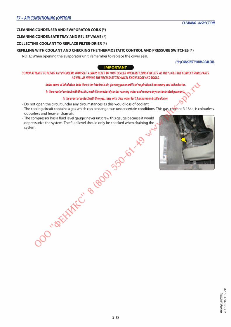
3 - 32
F7 – AIR CONDITIONING (OPTION)CLEANING - INSPECTION
CLEANING CONDENSER AND EVAPORATOR COILS (*)
CLEANING CONDENSATE TRAY AND RELIEF VALVE (*)
COLLECTING COOLANT TO REPLACE FILTER-DRIER (*)
REFILLING WITH COOLANT AND CHECKING THE THERMOSTATIC CONTROL AND PRESSURE SWITCHES (*)NOTE: When opening the evaporator unit, remember to replace the cover seal.
(*): (CONSULT YOUR DEALER).
IMPORTANT
DO NOT ATTEMPT TO REPAIR ANY PROBLEMS YOURSELF. ALWAYS REFER TO YOUR DEALER WHEN REFILLING CIRCUITS, AS THEY HOLD THE CORRECT SPARE PARTS,
AS WELL AS HAVING THE NECESSARY TECHNICAL KNOWLEDGE AND TOOLS.
In the event of inhalation, take the victim into fresh air, give oxygen or artificial respiration if necessary and call a doctor.
In the event of contact with the skin, wash it immediately under running water and remove any contaminated garments.
In the event of contact with the eyes, rinse with clear water for 15 minutes and call a doctor.
- Do not open the circuit under any circumstances as this would loss of coolant.
- The cooling circuit contains a gas which can be dangerous under certain conditions. This gas, coolant R-134a, is colourless,
odourless and heavier than air.
- The compressor has a fluid level gauge; never unscrew this gauge because it would
depressurize the system. The fluid level should only be checked when draining the
system.
6471
04 (1
3/06
/201
6)
MT 83
5 / 11
35 / 1
335
ST3B

3 - 33
6471
04 (1
3/06
/201
6)
MT 83
5 / 11
35 / 1
335
ST3B

3 - 34
G - EVERY 3000 HOURS OF SERVICECarry out the operations described previously as well as the following operations.
G1 – SAFETY DRY AIR FILTER CARTRIDGECHANGE
- For the disassembly and reassembly of the dry air filter cartridge, see: 3 -
MAINTENANCE: E1 - DRY AIR FILTER CARTRIDGE.
- Gently remove the dry air filter safety cartridge 1, taking care to avoid spilling the dust.
- Clean the gasket surface on the filter with a damp, clean lint-free cloth.
- Check the condition of the new safety cartridge before fitting (see: 3 - MAINTENANCE:
FILTERS, CARTRIDGES AND BELTS).
- Place the cartridge into the filter and position it by pressing the edges, not the middle.
NOTE: The periodicity for changing the safety cartridge is given for information only.
It must be changed once for every three changes of the dry air filter.
G2 – ALTERNATOR BELTCHANGE
- Open engine bonnet and the lower cover.
- Remove the protective casing 1.
REMOVING THE BELT - Loosen screws 2 by two to three turns.
- Release lock nut 3, and undo screw 4 sufficiently to be able to swivel the alternator
and release the alternator belt 5.
NOTE: Take advantage of belt removal to check the correct operation of the pulleys
and bearings (noise, rubbing, play, etc.).
REFITTING THE BELT - Refit a new alternator belt if required (see: 3 - MAINTENANCE: FILTERS CARTRIDGES
AND BELTS). Ensure that it is properly seated in the grooves of each pulley.
- Tighten screw 4 to tension the belt until the adjustment lug 6 is in contact with
the fixing screw 2.
- Retighten screws 2 (tightening torque 50 N.m).
- Undo the screws 4 by two turns and block the lock nut 3.
- Refit the protective casing 1.
1
2
2
2
34
5
6
1
6471
04 (1
3/06
/201
6)
MT 83
5 / 11
35 / 1
335
ST3B

3 - 35
6471
04 (1
3/06
/201
6)
MT 83
5 / 11
35 / 1
335
ST3B

3 - 36
H - OCCASIONAL MAINTENANCE
H1 – FUEL SYSTEMBLEEDING
These operations are to be carried out only in the following cases:
• A component of the fuel system replaced.
• A drained tank.
• Running out of fuel.
IMPORTANT
Fuel under high pressure that comes into contact with the skin can penetrate the skin and cause burns.
Spraying fuel under high pressure can cause a fire.
Failure to follow the inspection and maintenance instructions may result in serious injury.
Never work on the high pressure system.
Failure to follow this instruction may result in serious damage to the engine.
The high pressure furl system must be adjusted and repaired only by approved and suitably trained technicians.
Ensure that the level of fuel in the tank is sufficient and bleed in the following order:
- Open the engine bonnet.
- Check the condition of the fuel system.
- Operate the hand pump 1 approximately 80 times to remove air from the low pressure system.
- The engine is ready to be started up.
- Run the engine at idle for 5 minutes immediately after bleeding the fuel feed circuit, in order to ensure that the injection
pump has been bled thoroughly.
NOTE: If the engine functions correctly for a short time then stops or functions irregularly, check for possible leaks in the
low pressure circuit. If in doubt, contact your dealer.
H2 – "STATIONARY LIFT TRUCK" EXHAUST PARTICLE FILTERREGENERATE
IMPORTANT
Exhaust particle filter cleaning is an automated procedure activated by the operator when help
screens or or or are displayed.
- Park the lift truck in a safe and adequately ventilated place.
- Check the following points:
• forward/reverse selector in neutral,
• parking brake applied,
• boom angle less than 5°,
• Stabilisers raised MT1135 ST3B / MT1335 ST3B,
• engine water temperature greater than 70 °C,
• accelerator pedal released,
• high exhaust gas temperature indicator lamp off.
- Check that there is sufficient fuel.
- Start the lift truck and run the engine for a few minutes to bring it up to its operating temperature.
- Press down on the top of switch 1 for more than two seconds to begin the regeneration procedure.
- The help screen will be displayed, the indicator light will come on, then a beep will sound to confirm
that “stationary lift truck” particle filter regeneration is running. Failing this, the help screen will appear and
a beep will sound. Recheck the positioning of the lift truck and contact your dealer if necessary.
- The engine is running at 2000 rpm during the procedure.
IMPORTANT
The exhaust particle filter regeneration procedure must only be stopped in case of necessity.
If the operator presses the accelerator pedal or the forward/reverse selector during regeneration, the procedure will be automatically halted.
1
1
6471
04 (1
3/06
/201
6)
MT 83
5 / 11
35 / 1
335
ST3B
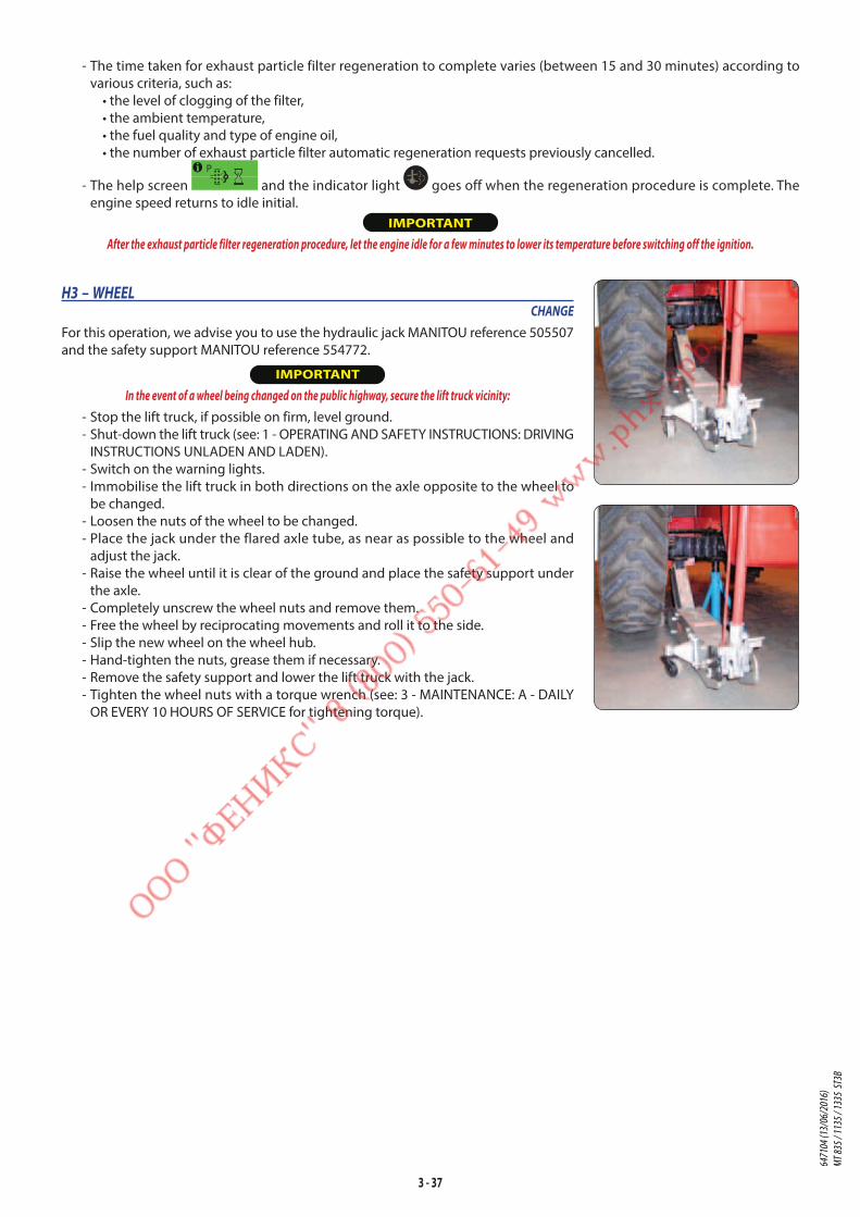
3 - 37
- The time taken for exhaust particle filter regeneration to complete varies (between 15 and 30 minutes) according to
various criteria, such as:
• the level of clogging of the filter,
• the ambient temperature,
• the fuel quality and type of engine oil,
• the number of exhaust particle filter automatic regeneration requests previously cancelled.
- The help screen and the indicator light goes off when the regeneration procedure is complete. The
engine speed returns to idle initial.
IMPORTANT
After the exhaust particle filter regeneration procedure, let the engine idle for a few minutes to lower its temperature before switching off the ignition.
H3 – WHEELCHANGE
For this operation, we advise you to use the hydraulic jack MANITOU reference 505507
and the safety support MANITOU reference 554772.
IMPORTANT
In the event of a wheel being changed on the public highway, secure the lift truck vicinity:
- Stop the lift truck, if possible on firm, level ground.
- Shut-down the lift truck (see: 1 - OPERATING AND SAFETY INSTRUCTIONS: DRIVING
INSTRUCTIONS UNLADEN AND LADEN).
- Switch on the warning lights.
- Immobilise the lift truck in both directions on the axle opposite to the wheel to
be changed.
- Loosen the nuts of the wheel to be changed.
- Place the jack under the flared axle tube, as near as possible to the wheel and
adjust the jack.
- Raise the wheel until it is clear of the ground and place the safety support under
the axle.
- Completely unscrew the wheel nuts and remove them.
- Free the wheel by reciprocating movements and roll it to the side.
- Slip the new wheel on the wheel hub.
- Hand-tighten the nuts, grease them if necessary.
- Remove the safety support and lower the lift truck with the jack.
- Tighten the wheel nuts with a torque wrench (see: 3 - MAINTENANCE: A - DAILY
OR EVERY 10 HOURS OF SERVICE for tightening torque).
6471
04 (1
3/06
/201
6)
MT 83
5 / 11
35 / 1
335
ST3B
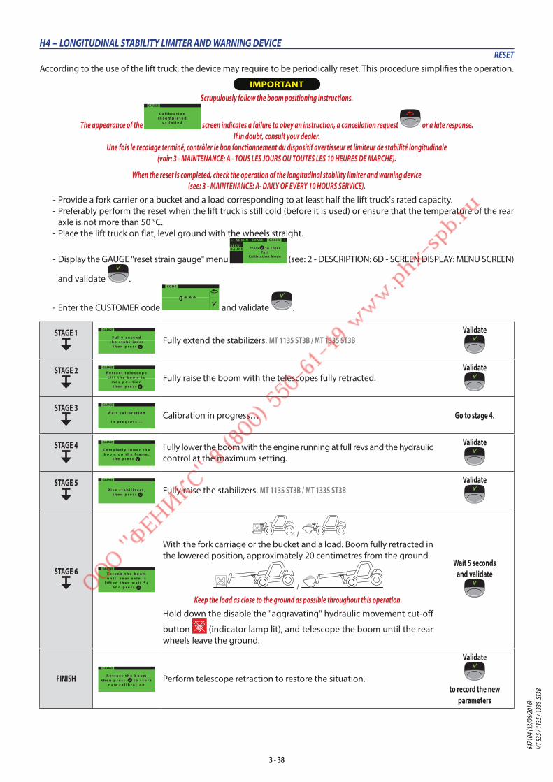
3 - 38
H4 – LONGITUDINAL STABILITY LIMITER AND WARNING DEVICERESET
According to the use of the lift truck, the device may require to be periodically reset. This procedure simplifies the operation.
IMPORTANT
Scrupulously follow the boom positioning instructions.
The appearance of the
GAUGE
C a l i b r a t i o ni n c o m p l e t e d
o r f a i l e d screen indicates a failure to obey an instruction, a cancellation request or a late response.
If in doubt, consult your dealer.
Une fois le recalage terminé, contrôler le bon fonctionnement du dispositif avertisseur et limiteur de stabilité longitudinale
(voir: 3 - MAINTENANCE: A - TOUS LES JOURS OU TOUTES LES 10 HEURES DE MARCHE).
When the reset is completed, check the operation of the longitudinal stability limiter and warning device
(see: 3 - MAINTENANCE: A- DAILY OF EVERY 10 HOURS SERVICE).
- Provide a fork carrier or a bucket and a load corresponding to at least half the lift truck's rated capacity.
- Preferably perform the reset when the lift truck is still cold (before it is used) or ensure that the temperature of the rear
axle is not more than 50 °C.
- Place the lift truck on flat, level ground with the wheels straight.
- Display the GAUGE "reset strain gauge" menu
Press to EnterFast
Calibration Mode
>< ADMIN C ALIBER ASE
GAUGESECU
(see: 2 - DESCRIPTION: 6D - SCREEN DISPLAY: MENU SCREEN)
and validate .
- Enter the CUSTOMER code
CODE
0 * * * and validate .
STAGE 1 GAUGE
F u l l y e x t e n dt h e s t a b i l i z e r s
t h e n p r e s s Fully extend the stabilizers. MT 1135 ST3B / MT 1335 ST3B
Validate
STAGE 2 GAUGE
R e t r a c t t e l e s c o p eL i f t t h e b o o m t o
m a x p o s i t i o nt h e n p r e s s
Fully raise the boom with the telescopes fully retracted.Validate
STAGE 3 GAUGE
W a i t c a l i b r a t i o n
i n p r o g r e s s . . .Calibration in progress… Go to stage 4.
STAGE 4 GAUGE
C o m p l e t l y l o w e r t h eb o o m o n t h e f r a m e .
t h e p r e s s
Fully lower the boom with the engine running at full revs and the hydraulic
control at the maximum setting.
Validate
STAGE 5 GAUGE
R i s e s t a b i l i z e r s ,t h e n p r e s s
Fully raise the stabilizers. MT 1135 ST3B / MT 1335 ST3BValidate
STAGE 6 GAUGE
E x t e n d t h e b o o mu n t i l r e a r a x l e i s
l i f t e d t h e n w a i t 5 sa n d p r e s s
/
With the fork carriage or the bucket and a load. Boom fully retracted in
the lowered position, approximately 20 centimetres from the ground.
/
Keep the load as close to the ground as possible throughout this operation.
Hold down the disable the "aggravating" hydraulic movement cut-off
button (indicator lamp lit), and telescope the boom until the rear
wheels leave the ground.
Wait 5 seconds and validate
FINISHGAUGE
R e t r a c t t h e b o o mt h e n p r e s s t o s t o r e
n e w c a l i b r a t i o nPerform telescope retraction to restore the situation.
Validate
to record the new
parameters
6471
04 (1
3/06
/201
6)
MT 83
5 / 11
35 / 1
335
ST3B

3 - 39
H5 – FRONT HEADLIGHTSADJUSTING
RECOMMENDED SETTING(as per standard ECE-76/756 76/761 ECE20)
Set to - 2% of the dipped beam in relation to the horizontal axis
of the headlamp.
ADJUSTING PROCEDUREPlace the unladen lift truck in the transport position and
perpendicular to a white wall on flat, level ground.
Check the tyre pressures (see: 2 - DESCRIPTION: FRONT AND REAR
TYRES).
Place the forward/reverse selector in neutral.
CALCULATING THE HEIGHT OF THE DIPPED BEAM (H2)• h1 = Height of the dipped beam in relation to the ground.
• h2 = Height of the adjusted beam.
• l = Distance between the dipped beam and the white wall.
H6 – BATTERY FAILURECHANGE
IMPORTANT
Operate the battery cut-out no less than 30 seconds after having switched off the ignition with the ignition key.
Handling and servicing a battery can be dangerous, take the following precautions:
• Wear protective goggles.
• Keep the battery horizontal.
• Never smoke or work near a naked flame.
• Work in a well-ventilated area.
In the event of electrolyte being spilled onto the skin or splashed in the eyes, rinse thoroughly with cold water for
15 minutes and call a doctor.
- Lift out protective casing 1.
- Change the battery 2.
1
2
+%
-%
l
h1h2
-2%
h2 = h1 - (l x 2 / 100)
h1
6471
04 (1
3/06
/201
6)
MT 83
5 / 11
35 / 1
335
ST3B

3 - 40
H7 – LIFT TRUCKTOWING
IMPORTANT
Do not tow the lift truck at more than 6 km/h over a maximum distance of 5 km.
This is a dangerous manoeuvre
Carefully chock the lift truck before towing, as the parking brake system is inoperative.
For adjusting the parking brake, please contact your dealer.
- Place the forward/reverse selection lever and gear shift lever in neutral.
- Chock the lift truck.
- Remove the cap 1.
- Loosen screw 2 with a pin wrench 3 to release the brake disk. Leave a minimum
clearance of 5 mm between the disk 4 and the brake pads 5.
- Put the towing device into place.
- Remove the chocks.
- Switch on the warning lights.
NOTE: Since there will be no steering or braking assistance, operate these controls
slowly. Avoid sudden jerky movements.
H8 – LIFT TRUCKSLINGING
- Take into account the position of the lift truck centre of gravity
for lifting.
A = 1497 mm B = 1383 mm MT 835 ST3BA = 1431mm B = 1449 mm MT 1135 ST3BA = 1491 mm B = 1389 mm MT 1335 ST3B
- Place the hooks in the fastening points 1 provided.
1
2
3
5 mm
5 5
4
1
1
1
1
BA
6471
04 (1
3/06
/201
6)
MT 83
5 / 11
35 / 1
335
ST3B
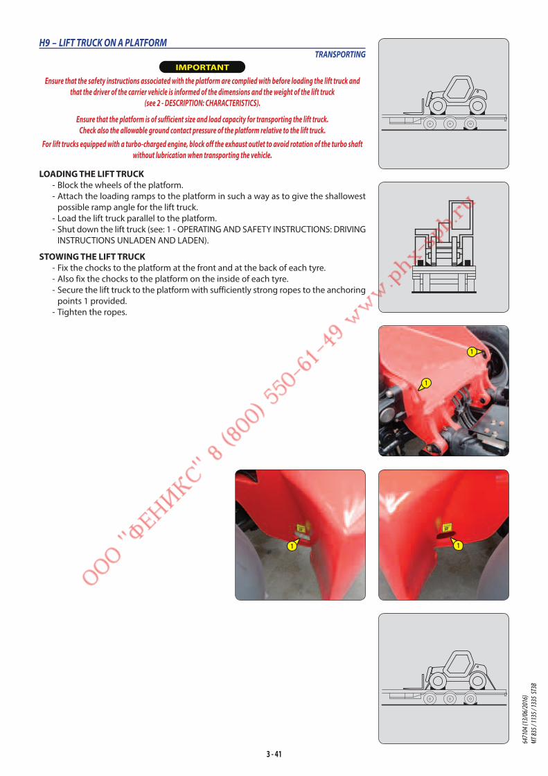
3 - 41
H9 – LIFT TRUCK ON A PLATFORMTRANSPORTING
IMPORTANT
Ensure that the safety instructions associated with the platform are complied with before loading the lift truck and
that the driver of the carrier vehicle is informed of the dimensions and the weight of the lift truck
(see 2 - DESCRIPTION: CHARACTERISTICS).
Ensure that the platform is of sufficient size and load capacity for transporting the lift truck.
Check also the allowable ground contact pressure of the platform relative to the lift truck.
For lift trucks equipped with a turbo-charged engine, block off the exhaust outlet to avoid rotation of the turbo shaft
without lubrication when transporting the vehicle.
LOADING THE LIFT TRUCK - Block the wheels of the platform.
- Attach the loading ramps to the platform in such a way as to give the shallowest
possible ramp angle for the lift truck.
- Load the lift truck parallel to the platform.
- Shut down the lift truck (see: 1 - OPERATING AND SAFETY INSTRUCTIONS: DRIVING
INSTRUCTIONS UNLADEN AND LADEN).
STOWING THE LIFT TRUCK - Fix the chocks to the platform at the front and at the back of each tyre.
- Also fix the chocks to the platform on the inside of each tyre.
- Secure the lift truck to the platform with sufficiently strong ropes to the anchoring
points 1 provided.
- Tighten the ropes.
1
1
1 1
6471
04 (1
3/06
/201
6)
MT 83
5 / 11
35 / 1
335
ST3B

3 - 42
6471
04 (1
3/06
/201
6)
MT 83
5 / 11
35 / 1
335
ST3B

4 - 1
4 - OPTIONAL
ATTACHMENTS
FOR USE WITH
THE RANGE
6471
04 (1
3/06
/201
6)
MT 83
5 / 11
35 / 1
335
ST3B

4 - 2
6471
04 (1
3/06
/201
6)
MT 83
5 / 11
35 / 1
335
ST3B

4 - 3
TABLE OF CONTENTS
4 - OPTIONAL ATTACHMENTS FOR USE WITH THE RANGE
INTRODUCTION 5
PICKING UP THE ATTACHMENTS 6
TECHNICAL SPECIFICATIONS OF ATTACHMENTS 8
ATTACHMENT SHIELDS 14
6471
04 (1
3/06
/201
6)
MT 83
5 / 11
35 / 1
335
ST3B

4 - 4
6471
04 (1
3/06
/201
6)
MT 83
5 / 11
35 / 1
335
ST3B
4 - 5
INTRODUCTION
- Your lift truck must be used with interchangeable equipment. These items are called: ATTACHMENTS.
- A wide range of attachments, specially designed and perfectly suitable for your lift truck is available and guaranteed by
MANITOU.
IMPORTANT
Only attachments approved by MANITOU are to be used on our lift trucks
(see: 4 - ADAPTABLE ATTACHMENTS IN OPTION ON THE RANGE: TECHNICAL SPECIFICATIONS OF ATTACHMENTS).
The manufacturer’s liability will be denied in case of modification or of attachment adaptation carried out without his knowing it.
- The attachments are delivered with a load chart concerning your lift truck. The operator’s manual and the load chart
should be kept in the places provided in the lift truck. For standard attachments, their use is governed by the instructions
contained on this notice.
IMPORTANT
Maximum loads are defined by the capacity of a lift truck taking account of the attachment’s mass and centre of gravity.
In the event of the attachment having less capacity than the lift truck, never exceed this limit.
- Some particular uses require the adaptation of the attachment which is not provided in the price-listed options. Optional
solutions exist, consult your dealer.
IMPORTANT
Depending on their size, certain attachments may, when the boom is lowered and retracted, come into contact with the front tyres and cause damage to them, if reverse
tilt is activated in the forward tilt direction.
TO REMOVE THIS RISK, EXTEND THE TELESCOPE TO A SUFFICIENT EXTENT FOR THE PARTICULAR LIFT TRUCK AND ATTACHMENT SO THAT THIS CONTACT IS NOT POSSIBLE.
SUSPENDED LOAD IMPORTANT
Suspended load MUST be handled with a lift truck designed for that purpose
(see: 1 - OPERATING AND SAFETY INSTRUCTIONS: LOAD HANDLING INSTRUCTIONS: H - TAKING-UP AND SETTING-DOWN A SUSPENDED LOAD).
USE THE SINGLE SIDE-SHIFT CARRIAGE IMPORTANT
The single side-shift carriage (TSDL) is only compatible with the following attachments:
• floating fork carriage (TFF)
• tilting fork carriage (PFB)
• loading bucket (CBR)
• concrete bucket (BB, BBG)
• spout bucket (GL)
• crane jib and crane jib with winch (P, PT, PO, PC)
• winch (H)
• fixed platform, swivelling platform, roofer’s platform.
It is prohibited to use any other attachments on the TSDL.
If it is being used with a loading bucket (CBR), the single side-shift carriage MUST be centred and no side-shift operations performed.
Attachments authorised for use on the TSDL must comply strictly with the applications for which they are designed.
It is prohibited to use them for any other application (for example, earth moving, excavation, desurfacing, back scraping, etc. for the loading bucket CBR) or any
application placing abnormal stress on the structure of the TSDL: risk of deformation which could cause the load to fall.
USE THE BUCKETS IMPORTANT
The MT 835 ST3B, MT 1135 ST3B and MT 1335 ST3B, are lift trucks essentially intended for handling. Occasional use with the buckets CBC/CBR/CB4x1 is authorised (only
with the boom completely retracted, in order to reduce stress on the boom head), but under no circumstances is intensive use for difficult applications (quarry, waste,
cereals, agriculture, etc) permissible.
6471
04 (1
3/06
/201
6)
MT 83
5 / 11
35 / 1
335
ST3B
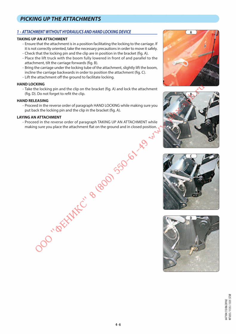
4 - 6
PICKING UP THE ATTACHMENTS
1 - ATTACHMENT WITHOUT HYDRAULICS AND HAND LOCKING DEVICE
TAKING UP AN ATTACHMENT - Ensure that the attachment is in a position facilitating the locking to the carriage. If
it is not correctly oriented, take the necessary precautions in order to move it safely.
- Check that the locking pin and the clip are in position in the bracket (fig. A).
- Place the lift truck with the boom fully lowered in front of and parallel to the
attachment, tilt the carriage forwards (fig. B).
- Bring the carriage under the locking tube of the attachment, slightly lift the boom,
incline the carriage backwards in order to position the attachment (fig. C).
- Lift the attachment off the ground to facilitate locking.
HAND LOCKING - Take the locking pin and the clip on the bracket (fig. A) and lock the attachment
(fig. D). Do not forget to refit the clip.
HAND RELEASING - Proceed in the reverse order of paragraph HAND LOCKING while making sure you
put back the locking pin and the clip in the bracket (fig. A).
LAYING AN ATTACHMENT - Proceed in the reverse order of paragraph TAKING UP AN ATTACHMENT while
making sure you place the attachment flat on the ground and in closed position.
A
B
C
D
6471
04 (1
3/06
/201
6)
MT 83
5 / 11
35 / 1
335
ST3B
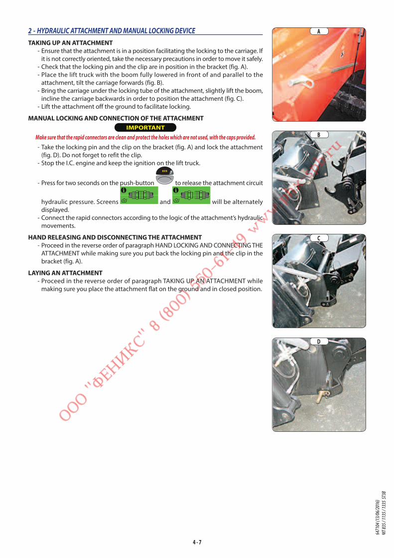
4 - 7
2 - HYDRAULIC ATTACHMENT AND MANUAL LOCKING DEVICE
TAKING UP AN ATTACHMENT - Ensure that the attachment is in a position facilitating the locking to the carriage. If
it is not correctly oriented, take the necessary precautions in order to move it safely.
- Check that the locking pin and the clip are in position in the bracket (fig. A).
- Place the lift truck with the boom fully lowered in front of and parallel to the
attachment, tilt the carriage forwards (fig. B).
- Bring the carriage under the locking tube of the attachment, slightly lift the boom,
incline the carriage backwards in order to position the attachment (fig. C).
- Lift the attachment off the ground to facilitate locking.
MANUAL LOCKING AND CONNECTION OF THE ATTACHMENT IMPORTANT
Make sure that the rapid connectors are clean and protect the holes which are not used, with the caps provided.
- Take the locking pin and the clip on the bracket (fig. A) and lock the attachment
(fig. D). Do not forget to refit the clip.
- Stop the I.C. engine and keep the ignition on the lift truck.
- Press for two seconds on the push-button to release the attachment circuit
hydraulic pressure. Screens and will be alternately
displayed.
- Connect the rapid connectors according to the logic of the attachment’s hydraulic
movements.
HAND RELEASING AND DISCONNECTING THE ATTACHMENT - Proceed in the reverse order of paragraph HAND LOCKING AND CONNECTING THE
ATTACHMENT while making sure you put back the locking pin and the clip in the
bracket (fig. A).
LAYING AN ATTACHMENT - Proceed in the reverse order of paragraph TAKING UP AN ATTACHMENT while
making sure you place the attachment flat on the ground and in closed position.
A
B
C
D
6471
04 (1
3/06
/201
6)
MT 83
5 / 11
35 / 1
335
ST3B
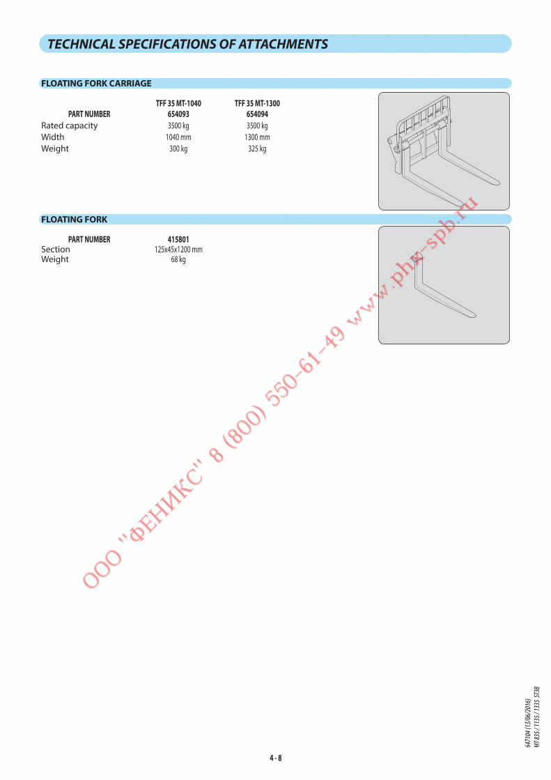
4 - 8
TECHNICAL SPECIFICATIONS OF ATTACHMENTS
FLOATING FORK CARRIAGE
TFF 35 MT-1040 TFF 35 MT-1300PART NUMBER 654093 654094
Rated capacity 3500 kg 3500 kg
Width 1040 mm 1300 mm
Weight 300 kg 325 kg
FLOATING FORK
PART NUMBER 415801Section 125x45x1200 mmWeight 68 kg
6471
04 (1
3/06
/201
6)
MT 83
5 / 11
35 / 1
335
ST3B

4 - 9
STANDARDISED TILTING FORK CARRIAGE
PFB 35 N MT-1260 S2 PFB 35 N MT-1470 S2 PFB 35 N MT-1580 S2PART NUMBER 653744 653745 653746
Rated capacity 3500 kg 3500 kg 3500 kg
Width 1260 mm 1470 mm 1580 mm
Weight 95 kg 120 kg 125 kg
STANDARDISED SIDE-SHIFT CARRIAGE
Use is prohibited with the optional single side-shift carriage (TSDL).TDL 3T5 L1260 FEM3 TDL 5T L1470 FEM3 TDL 5T L1580 FEM3
PART NUMBER 751375 751376 751377Rated capacity 3500 kg 5000 kg 5000 kg
Side-shift 2x100 mm 2x100 mm 2x100 mm
Width 1260 mm 1470 mm 1580 mm
Weight 79 kg 167 kg 177 kg
STANDARDISED FORK
PART NUMBER 415618Section 125x45x1200 mm
Weight 72 kg
LOAD BACK REST
PART NUMBER 556008 555325 556010Width 1260 mm 1470 mm 1580 mm
Weight 39 kg 41 kg 42 kg64
7104
(13/
06/2
016)
MT
835 /
1135
/ 133
5 ST
3B
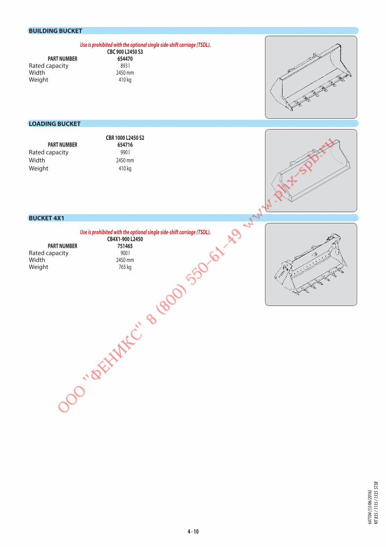
4 - 10
BUILDING BUCKET
Use is prohibited with the optional single side-shift carriage (TSDL).CBC 900 L2450 S3
PART NUMBER 654470Rated capacity 893 lWidth 2450 mmWeight 410 kg
LOADING BUCKET
CBR 1000 L2450 S2PART NUMBER 654716
Rated capacity 990 l
Width 2450 mm
Weight 410 kg
BUCKET 4X1
Use is prohibited with the optional single side-shift carriage (TSDL).CB4X1-900 L2450
PART NUMBER 751465Rated capacity 900 lWidth 2450 mmWeight 765 kg
6471
04 (1
3/06
/201
6)
MT 83
5 / 11
35 / 1
335
ST3B
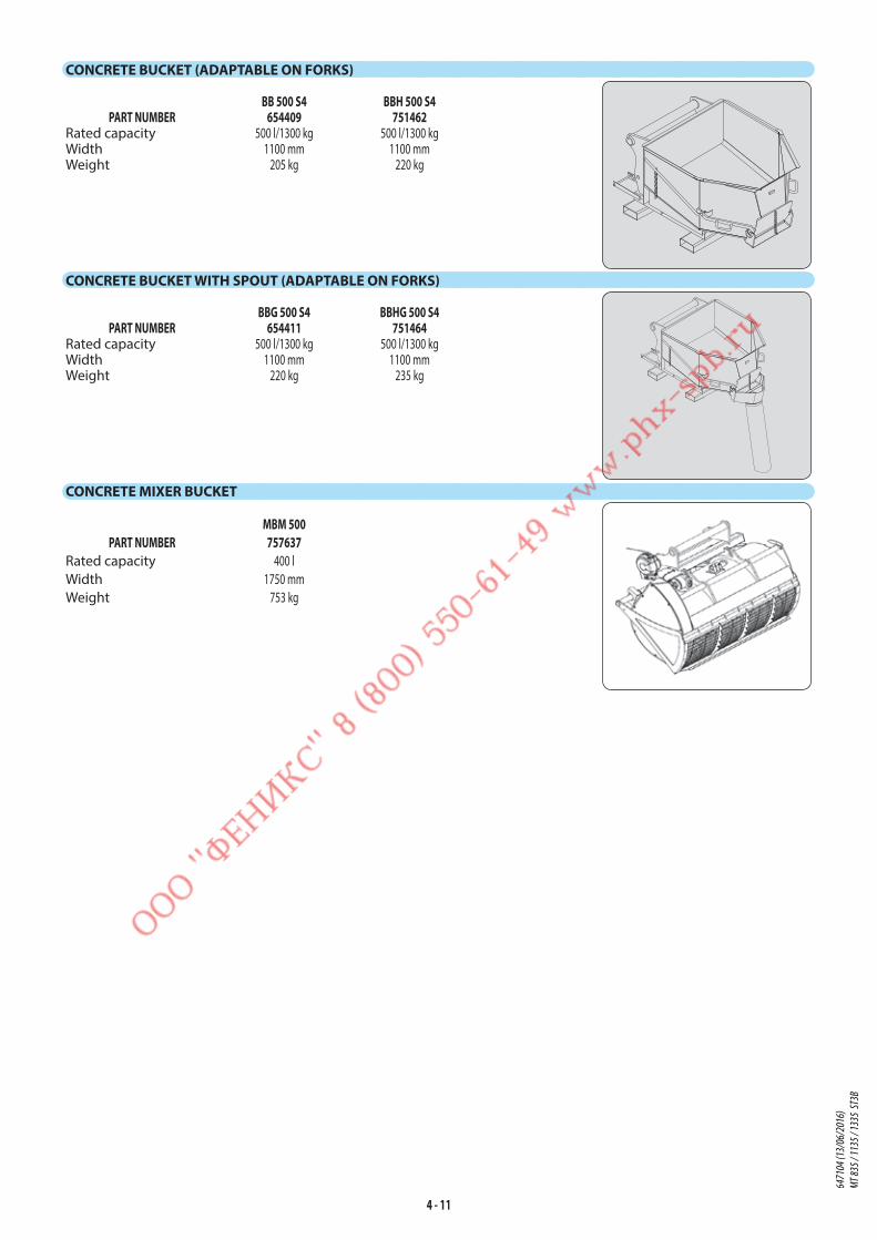
4 - 11
CONCRETE BUCKET (ADAPTABLE ON FORKS)
BB 500 S4 BBH 500 S4PART NUMBER 654409 751462
Rated capacity 500 l/1300 kg 500 l/1300 kgWidth 1100 mm 1100 mmWeight 205 kg 220 kg
CONCRETE BUCKET WITH SPOUT (ADAPTABLE ON FORKS)
BBG 500 S4 BBHG 500 S4PART NUMBER 654411 751464
Rated capacity 500 l/1300 kg 500 l/1300 kgWidth 1100 mm 1100 mmWeight 220 kg 235 kg
CONCRETE MIXER BUCKET
MBM 500PART NUMBER 757637
Rated capacity 400 l
Width 1750 mm
Weight 753 kg
6471
04 (1
3/06
/201
6)
MT 83
5 / 11
35 / 1
335
ST3B

4 - 12
CRANE JIB
P 600 MT S3PART NUMBER 653228
Rated capacity 600 kgWeight 170 kg
CRANE JIB
P 4000 MT S2PART NUMBER 653226
Rated capacity 4000 kg/1200 kgWeight 210 kg
CRANE JIB
PC 40 PC 50PART NUMBER 708553 708544
Rated capacity 4000 kg 5000 kgWeight 120 kg 120 kg
WINCH
H3TPART NUMBER 885236
Rated capacity 3000 kgWeight 310 kg
6471
04 (1
3/06
/201
6)
MT 83
5 / 11
35 / 1
335
ST3B

4 - 13
6471
04 (1
3/06
/201
6)
MT 83
5 / 11
35 / 1
335
ST3B
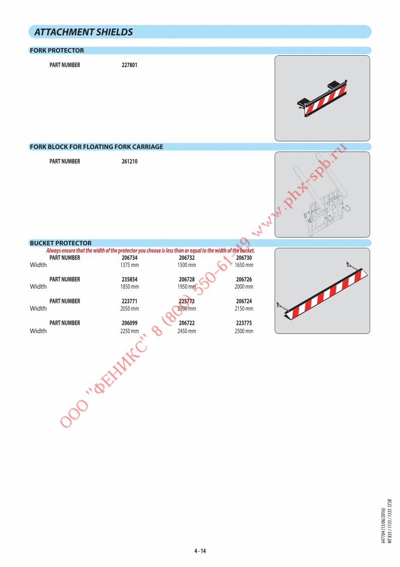
4 - 14
ATTACHMENT SHIELDS
FORK PROTECTOR
PART NUMBER 227801
FORK BLOCK FOR FLOATING FORK CARRIAGE
PART NUMBER 261210
BUCKET PROTECTORAlways ensure that the width of the protector you choose is less than or equal to the width of the bucket.
PART NUMBER 206734 206732 206730Width 1375 mm 1500 mm 1650 mm
PART NUMBER 235854 206728 206726Width 1850 mm 1950 mm 2000 mm
PART NUMBER 223771 223773 206724Width 2050 mm 2100 mm 2150 mm
PART NUMBER 206099 206722 223775Width 2250 mm 2450 mm 2500 mm
6471
04 (1
3/06
/201
6)
MT 83
5 / 11
35 / 1
335
ST3B