implementation of ifc-based web server for collaborative building design between architects and...
TRANSCRIPT
www.elsevier.com/locate/autcon
Automation in Constructio
Implementation of IFC-based web server for collaborative building
design between architects and structural engineers
Po-Han Chena,*, Lu Cuia, Caiyun Wana, Qizhen Yangb, Seng Kiong Tinga,
Robert L.K. Tionga
aSchool of Civil and Environmental Engineering, Nanyang Technological University, Singapore 639798, SingaporebSingapore Institute of Manufacturing Technology, Singapore 638075, Singapore
Accepted 27 August 2004
Abstract
This paper presents the implementation of an Industry Foundation Class-based (IFC-based) information server for web-
enabled collaborative building design between the architect and structural engineer. In this research, the Java 2 Platform,
Enterprise Edition (J2EE) standard is employed to build the framework of a design information server; the web and XML
technologies are used to implement the collaboration and information sharing mechanisms in the server. The Industry
Foundation Classes (IFCs) are adopted as the information model of the server to facilitate the interoperability among
multidisciplinary AEC software applications. The current implementation of the server system supports the automatic
transformation of the design model contents and representations from the architectural domain to the structural domain, and
remote visualization and interaction by Java applet and the Java3D technology. An algorithm that is able to deduce the
topological relationship among different structural elements has been proposed in this paper. A case study is presented at the
end of the paper to illustrate the use of the information server for the architectural and structural design collaboration.
D 2004 Elsevier B.V. All rights reserved.
Keywords: Industry Foundation Classes (IFCs); Information server; Collaborative building design; Web-enabled services
1. Introduction architectural elements, while structural design on
Traditionally, architectural design and structural
design are two separate steps with distinct objectives
in the building design process. Architectural design is
focused on defining the space arrangement of various
0926-5805/$ - see front matter D 2004 Elsevier B.V. All rights reserved.
doi:10.1016/j.autcon.2004.08.013
* Corresponding author. Tel.: +65 6790 4562; fax: +65 6791
0676.
E-mail address: [email protected] (P.-H. Chen).
analyzing the mechanical properties of building ele-
ments and structure. The two design processes are
closely related as architecture design, which defines the
geometric information about building elements, pro-
vides the input information for structural design. Thus,
the success of a building design process is highly
dependent upon effective coordination among diverse
design teams. With the prevalence of information
technology (IT) applications in the AEC industry, the
n 14 (2005) 115–128
P.-H. Chen et al. / Automation in Construction 14 (2005) 115–128116
efficiency and effectiveness of building design could
be achieved through the interoperability and data
exchange among different computer-aided design and
analysis tools. Therefore, an IFC-based web server for
collaborative building design between architects and
structural engineers was proposed to meet this purpose.
Industry Foundation Classes (IFCs) [1,2] are a set
of building product model specifications developed by
the International Alliance for Interoperability (IAI)
[3,4] for product data representation and exchange in
the Architecture, Engineering, Construction/Facilities
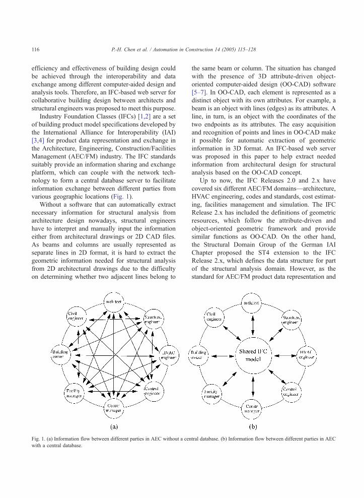
Management (AEC/FM) industry. The IFC standards
suitably provide an information sharing and exchange
platform, which can couple with the network tech-
nology to form a central database server to facilitate
information exchange between different parties from
various geographic locations (Fig. 1).
Without a software that can automatically extract
necessary information for structural analysis from
architecture design nowadays, structural engineers
have to interpret and manually input the information
either from architectural drawings or 2D CAD files.
As beams and columns are usually represented as
separate lines in 2D format, it is hard to extract the
geometric information needed for structural analysis
from 2D architectural drawings due to the difficulty
on determining whether two adjacent lines belong to
Fig. 1. (a) Information flow between different parties in AEC without a cen
with a central database.
the same beam or column. The situation has changed
with the presence of 3D attribute-driven object-
oriented computer-aided design (OO-CAD) software
[5–7]. In OO-CAD, each element is represented as a
distinct object with its own attributes. For example, a
beam is an object with lines (edges) as its attributes. A
line, in turn, is an object with the coordinates of the
two endpoints as its attributes. The easy acquisition
and recognition of points and lines in OO-CAD make
it possible for automatic extraction of geometric
information in 3D format. An IFC-based web server
was proposed in this paper to help extract needed
information from architectural design for structural
analysis based on the OO-CAD concept.
Up to now, the IFC Releases 2.0 and 2.x have
covered six different AEC/FM domains—architecture,
HVAC engineering, codes and standards, cost estimat-
ing, facilities management and simulation. The IFC
Release 2.x has included the definitions of geometric
resources, which follow the attribute-driven and
object-oriented geometric framework and provide
similar functions as OO-CAD. On the other hand,
the Structural Domain Group of the German IAI
Chapter proposed the ST4 extension to the IFC
Release 2.x, which defines the data structure for part
of the structural analysis domain. However, as the
standard for AEC/FM product data representation and
tral database. (b) Information flow between different parties in AEC

Fig. 2. EXPRESS-G for geometric representation of an object.
P.-H. Chen et al. / Automation in Construction 14 (2005) 115–128 117
exchange, IFC does not include the algorithm for
deducing geometric information needed by structural
design from architectural drawings. Thus, this func-
tionality has to be added externally to improve the
efficiency and effectiveness of building design.
Fig. 3. Example of local relative placement.
2. Geometric representation of products in IFC
The definitions of geometric representations in the
IFC Releases 2.0 and 2.x are quite close to the well-
approved STEP geometric definition of ISO 10303-
42:1994 [8]. Any object in IFC with a geometric
representation has two attributes: ObjectPlacement
and Representation. ObjectPlacement has the type of
IfcObjectPlacement and stores the placement infor-
mation of an object. It could be absolute (relative to
the global coordinate), relative (relative to the
ObjectPlacement of another product), or constrained
(relative to the grid axes). Representation has the type
of IfcProductRepresentation and stores the shape
representations of an object. Its location is defined
within the context of ObjectPlacement. Fig. 2 shows
the EXPRESS-G (a graphic notation for EXPRESS)
diagram for the geometric representation of a product,
which could be either a beam or a column.
The default setting for the placement of an object
is relative placement, defined by IfcLocalPlacement
with a PlacementRelTo attribute to specify the
referencing spatial context. For example, point A in
Fig. 3 has a local placement value of (2, 2, 1) with
respect to a coordinate xWyWzW. The origin of the
context xWyWzW has a local placement value of (�1,
5, 3) with respect to another local coordinate xVyVzV.In turn, the origin of context xVyVzV has a local
placement value of (1, 0, 3) with respect to the
global coordinate xyz. In web applications, the local
placement of an object should be transferred to the
global placement for the deduction of topological
relationship.
There are two geometric representations of shape:
the explicit geometric representation of shape and the
attribute-driven representation of shape. Explicit
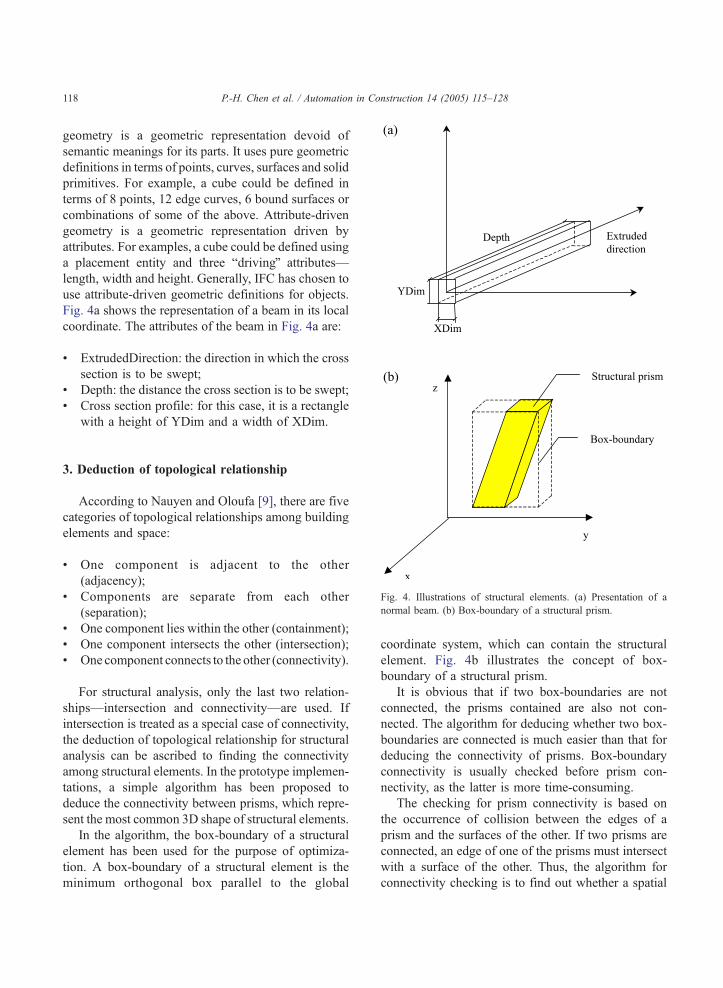
Fig. 4. Illustrations of structural elements. (a) Presentation of a
normal beam. (b) Box-boundary of a structural prism.
P.-H. Chen et al. / Automation in Construction 14 (2005) 115–128118
geometry is a geometric representation devoid of
semantic meanings for its parts. It uses pure geometric
definitions in terms of points, curves, surfaces and solid
primitives. For example, a cube could be defined in
terms of 8 points, 12 edge curves, 6 bound surfaces or
combinations of some of the above. Attribute-driven
geometry is a geometric representation driven by
attributes. For examples, a cube could be defined using
a placement entity and three bdrivingQ attributes—
length, width and height. Generally, IFC has chosen to
use attribute-driven geometric definitions for objects.
Fig. 4a shows the representation of a beam in its local
coordinate. The attributes of the beam in Fig. 4a are:
! ExtrudedDirection: the direction in which the cross
section is to be swept;
! Depth: the distance the cross section is to be swept;
! Cross section profile: for this case, it is a rectangle
with a height of YDim and a width of XDim.
3. Deduction of topological relationship
According to Nauyen and Oloufa [9], there are five
categories of topological relationships among building
elements and space:
! One component is adjacent to the other
(adjacency);
! Components are separate from each other
(separation);
! One component lies within the other (containment);
! One component intersects the other (intersection);
! One component connects to the other (connectivity).
For structural analysis, only the last two relation-
ships—intersection and connectivity—are used. If
intersection is treated as a special case of connectivity,
the deduction of topological relationship for structural
analysis can be ascribed to finding the connectivity
among structural elements. In the prototype implemen-
tations, a simple algorithm has been proposed to
deduce the connectivity between prisms, which repre-
sent the most common 3D shape of structural elements.
In the algorithm, the box-boundary of a structural
element has been used for the purpose of optimiza-
tion. A box-boundary of a structural element is the
minimum orthogonal box parallel to the global
coordinate system, which can contain the structural
element. Fig. 4b illustrates the concept of box-
boundary of a structural prism.
It is obvious that if two box-boundaries are not
connected, the prisms contained are also not con-
nected. The algorithm for deducing whether two box-
boundaries are connected is much easier than that for
deducing the connectivity of prisms. Box-boundary
connectivity is usually checked before prism con-
nectivity, as the latter is more time-consuming.
The checking for prism connectivity is based on
the occurrence of collision between the edges of a
prism and the surfaces of the other. If two prisms are
connected, an edge of one of the prisms must intersect
with a surface of the other. Thus, the algorithm for
connectivity checking is to find out whether a spatial

Fig. 5. Illustrations of connectivity checking algorithm. (a) A spatial
line colliding with a three-vertex facet. (b) Illustration of the
algorithm to determine whether P is inside DPaPbPc.
P.-H. Chen et al. / Automation in Construction 14 (2005) 115–128 119
line segment has a common point with a planar three-
vertex facet (Fig. 5a). The examination of collision
between complex polygons can be started by triangu-
lating them into three-vertex facets.
The coefficients, A, B, C, and D, for the spatial
plane that contains the facet in Fig. 5a can be
calculated from the coordinates of the three vertices
using Eqs. (1) and (2), where Pax, Pay, and Paz refer to
the x, y, and z values of the coordinate of point Pa.
A;B;Cð Þ ¼ Pb � Pað Þ Pc � Pað Þ ð1ÞD ¼ � APax þ BPay þ CPaz
� �ð2Þ
Four steps are summarized below for intersection
checking between a line segment and a facet, as
shown in Fig. 5a:
1. Check whether the line that contains the segment
and the plane that contains the facet are parallel;
2. Find the intersection of the line that contains the
segment and the plane that contains the facet;
3. Check whether the intersection point is inside the
line segment;
4. Check whether the intersection point is inside the
facet.
P in Fig. 5a illustrates the intersection point. Its
position can be determined through the calculation of
coefficient l in Eq. (3), where P1x, P1y, P1z and P2x,
P2y, P2z refer to the x, y and z values of the
coordinates of point P1 and P2, respectively.
l ¼ AP1x þ BP1y þ CP1z þ D
A P1x � P2xð Þ þ B P1y � P2y
� �þ C P1z � P2zð Þ
ð3ÞIf the denominator of Eq. (3) is zero, then the line is
parallel to the facet. If l is between 0 and 1 (inclusive
of 1), the intersection point is inside the line segment.
The final step, which checks whether the inter-
section point is inside the facet, is based on the
calculation of area. If the intersection point is inside
the facet (Fig. 5b), the total area of the three triangles
DPPaPb, DPPbPc, and DPPcPa (Eq. (4)) must equal
the area of DPaPbPc (Eq. (5)).
DPPaPb þ DPPaPc þ DPPcPb
¼ 1
2j Pa � Pð Þ Pb � Pð Þj þ j Pa � Pð Þ Pc � Pð Þjð
þ j Pc � Pð Þ Pb � Pð ÞjÞð4Þ
DPaPbPc ¼1
2j Pc � Pað Þ Pb � Pað Þj ð5Þ
4. Construction of structural model
A mechanical model for architecture should
include idealized structural elements, their mechanical
connectivity, support conditions, mechanical proper-
ties and loadings [10]. Among all the items, only
idealized structural elements and connectivity infor-
mation could be deduced from 3D architectural
models. The others need to be input externally. There
are three steps in the deductive process:
1. Finding the connectivity between structural ele-
ments;
2. Defining the idealized structural elements;
3. Finding the joints between two connected struc-
tural elements.
For a prism, its corresponding idealized structural
element is the line segment connecting the centroids
of the two end cross-sectional surfaces (Fig. 6). A
joint can be defined as the intersection point of two
idealized structural elements if they are on the same
spatial plane or the nearest point of one element to the
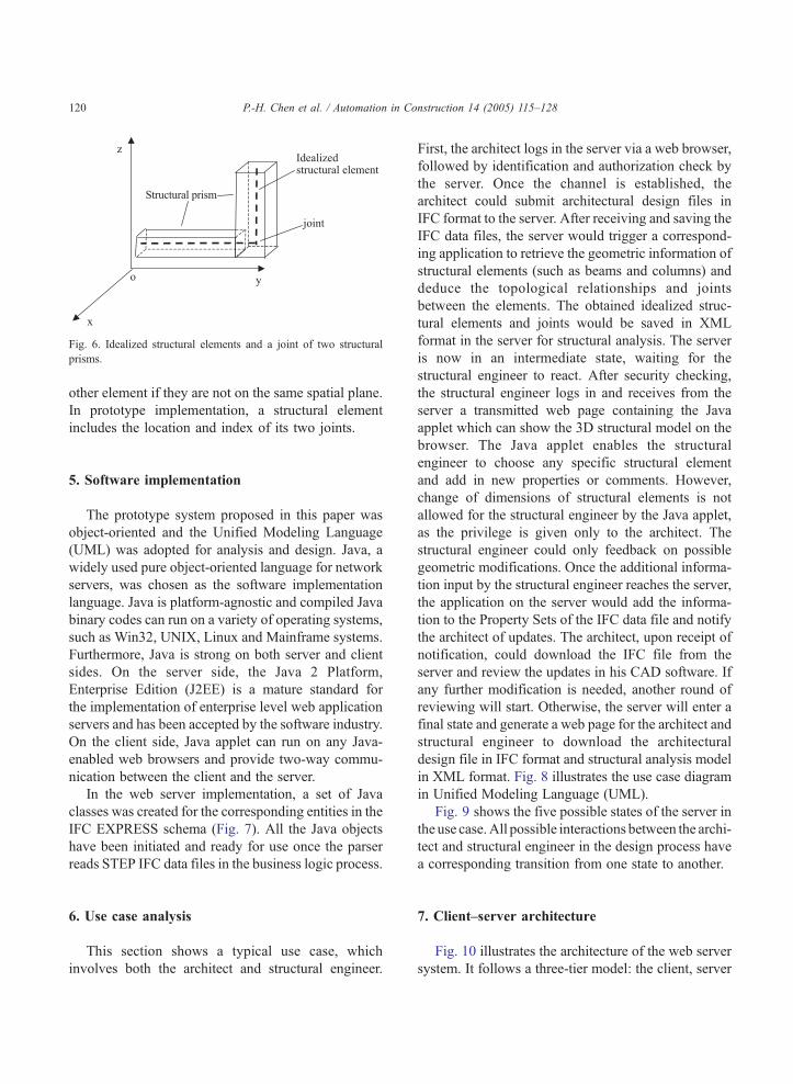
Fig. 6. Idealized structural elements and a joint of two structural
prisms.
P.-H. Chen et al. / Automation in Construction 14 (2005) 115–128120
other element if they are not on the same spatial plane.
In prototype implementation, a structural element
includes the location and index of its two joints.
5. Software implementation
The prototype system proposed in this paper was
object-oriented and the Unified Modeling Language
(UML) was adopted for analysis and design. Java, a
widely used pure object-oriented language for network
servers, was chosen as the software implementation
language. Java is platform-agnostic and compiled Java
binary codes can run on a variety of operating systems,
such as Win32, UNIX, Linux and Mainframe systems.
Furthermore, Java is strong on both server and client
sides. On the server side, the Java 2 Platform,
Enterprise Edition (J2EE) is a mature standard for
the implementation of enterprise level web application
servers and has been accepted by the software industry.
On the client side, Java applet can run on any Java-
enabled web browsers and provide two-way commu-
nication between the client and the server.
In the web server implementation, a set of Java
classes was created for the corresponding entities in the
IFC EXPRESS schema (Fig. 7). All the Java objects
have been initiated and ready for use once the parser
reads STEP IFC data files in the business logic process.
6. Use case analysis
This section shows a typical use case, which
involves both the architect and structural engineer.
First, the architect logs in the server via a web browser,
followed by identification and authorization check by
the server. Once the channel is established, the
architect could submit architectural design files in
IFC format to the server. After receiving and saving the
IFC data files, the server would trigger a correspond-
ing application to retrieve the geometric information of
structural elements (such as beams and columns) and
deduce the topological relationships and joints
between the elements. The obtained idealized struc-
tural elements and joints would be saved in XML
format in the server for structural analysis. The server
is now in an intermediate state, waiting for the
structural engineer to react. After security checking,
the structural engineer logs in and receives from the
server a transmitted web page containing the Java
applet which can show the 3D structural model on the
browser. The Java applet enables the structural
engineer to choose any specific structural element
and add in new properties or comments. However,
change of dimensions of structural elements is not
allowed for the structural engineer by the Java applet,
as the privilege is given only to the architect. The
structural engineer could only feedback on possible
geometric modifications. Once the additional informa-
tion input by the structural engineer reaches the server,
the application on the server would add the informa-
tion to the Property Sets of the IFC data file and notify
the architect of updates. The architect, upon receipt of
notification, could download the IFC file from the
server and review the updates in his CAD software. If
any further modification is needed, another round of
reviewing will start. Otherwise, the server will enter a
final state and generate a web page for the architect and
structural engineer to download the architectural
design file in IFC format and structural analysis model
in XML format. Fig. 8 illustrates the use case diagram
in Unified Modeling Language (UML).
Fig. 9 shows the five possible states of the server in
the use case.All possible interactions between the archi-
tect and structural engineer in the design process have
a corresponding transition from one state to another.
7. Client–server architecture
Fig. 10 illustrates the architecture of the web server
system. It follows a three-tier model: the client, server
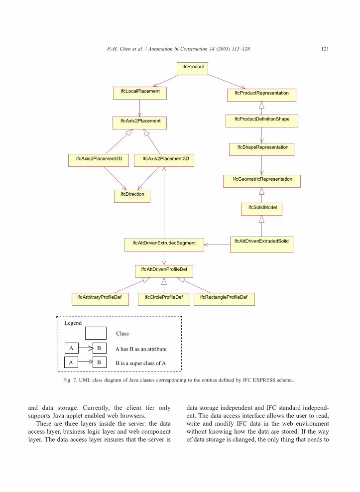
Fig. 7. UML class diagram of Java classes corresponding to the entities defined by IFC EXPRESS schema.
P.-H. Chen et al. / Automation in Construction 14 (2005) 115–128 121
and data storage. Currently, the client tier only
supports Java applet enabled web browsers.
There are three layers inside the server: the data
access layer, business logic layer and web component
layer. The data access layer ensures that the server is
data storage independent and IFC standard independ-
ent. The data access interface allows the user to read,
write and modify IFC data in the web environment
without knowing how the data are stored. If the way
of data storage is changed, the only thing that needs to

Fig. 8. Use case diagram for web server application.
P.-H. Chen et al. / Automation in Construction 14 (2005) 115–128122
be modified is the coding of the data access interface.
As the IFC EXPRESS schema is currently undergoing
some changes, to ensure the reusability of the codes,
Fig. 9. State diagram o
the properties of building components are encapsu-
lated in Java Beans, which could be initiated by
accessing IFC data through the data access interface.
f the web server.
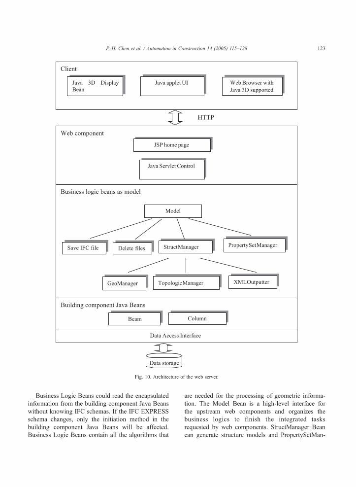
Fig. 10. Architecture of the web server.
P.-H. Chen et al. / Automation in Construction 14 (2005) 115–128 123
Business Logic Beans could read the encapsulated
information from the building component Java Beans
without knowing IFC schemas. If the IFC EXPRESS
schema changes, only the initiation method in the
building component Java Beans will be affected.
Business Logic Beans contain all the algorithms that
are needed for the processing of geometric informa-
tion. The Model Bean is a high-level interface for
the upstream web components and organizes the
business logics to finish the integrated tasks
requested by web components. StructManager Bean
can generate structure models and PropertySetMan-

P.-H. Chen et al. / Automation in Construction 14 (2005) 115–128124
ager Bean can add property sets to IFC files.
GeoManager Bean, TopologicalManager Bean and
XMLOutputter Bean are for special functions like
generating global coordinates, deducing topological
relationships between structural elements and out-
putting structural models in XML format. The
hierarchical structure of Business Logic Beans makes
the software design work easier to manage. The web
component contains JavaServer Pages (JSP), which
could dynamically generate web pages according to
the state of the server, and Java Servlet Control,
which could receive input from the client and
dispatch the client’s request to the Model Bean. This
design follows the popular Model-View-Controller
(MVC) architecture, which is illustrated as the class
diagram in Fig. 11.
The client side comprises a Java-enabled web
browser which supports Java3D. The Java 3D Display
Bean reads XML-format structural models from the
server and displays 3D outcomes on the browser. It
allows the user to input data to an element through a
pop-up window which could be triggered by clicking
on the element. As Java is platform independent, there
Fig. 11. Class diagram of the Mo
are no specific requirements on the operating systems
used by client machines.
8. Case study
This section shows the implementation of collab-
orative building design with the developed web
server.
First, the architect logs in the web site from a
remote computer (Fig. 12a). After identification and
authorization check on the architect, the server would
generate a JSP page that would allow the architect to
upload an IFC-format seven-story building with a
total of 741 beams and 442 columns (Fig. 13a). Upon
receipt of the building file, the server generates a
corresponding structural analysis model and saves it
in XML format.
The structural engineer at another location could
log in the server via a secured channel and view the
structural analysis model on his browser. Although the
structural engineer could not directly modify the
structural analysis model generated by the server, he
del-View-Controller model.
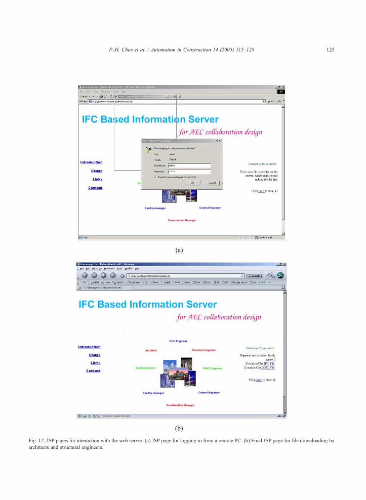
Fig. 12. JSP pages for interaction with the web server. (a) JSP page for logging in from a remote PC. (b) Final JSP page for file downloading by
architects and structural engineers.
P.-H. Chen et al. / Automation in Construction 14 (2005) 115–128 125
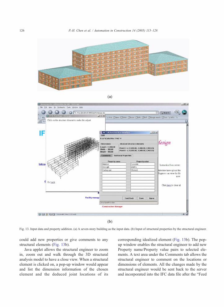
Fig. 13. Input data and property addition. (a) A seven-story building as the input data. (b) Input of structural properties by the structural engineer.
P.-H. Chen et al. / Automation in Construction 14 (2005) 115–128126
could add new properties or give comments to any
structural elements (Fig. 13b).
Java applet allows the structural engineer to zoom
in, zoom out and walk through the 3D structural
analysis model to have a close view. When a structural
element is clicked on, a pop-up window would appear
and list the dimension information of the chosen
element and the deduced joint locations of its
corresponding idealized element (Fig. 13b). The pop-
up window enables the structural engineer to add new
Property name/Property value pairs to selected ele-
ments. A text area under the Comments tab allows the
structural engineer to comment on the locations or
dimensions of elements. All the changes made by the
structural engineer would be sent back to the server
and incorporated into the IFC data file after the bFeed
P.-H. Chen et al. / Automation in Construction 14 (2005) 115–128 127
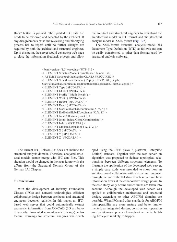
BackQ button is pressed. The updated IFC data file
needs to be reviewed and accepted by the architect. If
any disagreements exist, the reviewing and modifying
process has to repeat until no further changes are
required by both the architect and structural engineer.
Up to this point, the server would generate a web page
to close the information feedback process and allow
the architect and structural engineer to download the
architectural model in IFC format and the structural
analysis model in XML format (Fig. 12b).
The XML-format structural analysis model has
Document Type Definition (DTD) as follows and can
be easily transformed to other data formats used by
structural analysis software.
The current IFC Release 2.x does not include the
structural analysis domain. Therefore, analyzed struc-
tural models cannot merge with IFC data files. This
situation would be changed in the near future with the
efforts from the Structural Domain Group of the
German IAI Chapter.
9. Conclusions
With the development of Industry Foundation
Classes (IFCs) and network technologies, efficient
collaborative design between architects and structural
engineers becomes realistic. In this paper, an IFC-
based web server that could automatically extract
geometric information from OO-CAD (3D attribute-
driven object-oriented computer-aided design) archi-
tectural drawings for structural analyses was devel-
oped using the J2EE (Java 2 platform, Enterprise
Edition) standard. Together with the web server, an
algorithm was proposed to deduce topological rela-
tionships between different structural elements. To
illustrate the application of the developed web server,
a simple case study was provided to show how an
architect could collaborate with a structural engineer
through the use of the IFC-based web server and how
information flows at the collaborative design phase. In
the case study, only beams and columns are taken into
account. Although the developed web server was
applied to collaborative architectural and structural
design, extensions to other AEC/FM domains are
possible. When IFCs and other standards for AEC/FM
interoperability are more mature and better imple-
mented, an integrated design, construction, operation
and maintenance process throughout an entire build-
ing life cycle is likely to happen.

P.-H. Chen et al. / Automation in Construction 14 (2005) 115–128128
References
[1] Jeffery Wix, Thomas Liebich, Industry foundation classes:
some business question examined, Proceedings of 2nd EC-
PPM conference, Watford, UK Oct 19–21, 1998.
[2] International Alliance for Interoperability Modelling Support
Group, Industry Foundation Classes, Release 2.x IFC Object
Model Reference, July 2002.
[3] IAI International official web site, http://www.iai-international.
org/.
[4] M.A. Hassanain, T.M. Froese, D.J. Vanier, Development of a
maintenance management model based on IAI standards,
Artificial Intelligence in Engineering 15 (2001) 177–193.
[5] P. Heck, K. Wassermann, Object-oriented CAD-model for
building design, in: P. Pahl, H. Werner (Eds.), Computing in
Civil and Building Engineering, vol. 1, 1995, pp. S.89–S.95
Rotterdam.
[6] Thomas Liebich, Jeffery Wix, Standard Analysis-Current AEC
Situation-Building Models, edited by Thomas Liebich, AEC 3,
pp. 10–11.
[7] Yang, Q., Cui, L., 2003. Interoperable and Extensible Design
Information Modelling, to appear in Proceedings of CAAD
Futures 2003, Taiwan.
[8] ISO 10303-42 1994 (E), Industrial automation systems and
integration-product data representation and exchange.
[9] Tang-Hung Nauyen, Amr A. Oloufa, Computer-generated
building data: topological information, Journal of Computing
in Civil Engineering (2001 (Oct)) 268–274.
[10] Christoph Hfrenbaum, Lehrstuhl Stahl-und Leichtmetallbau,
IAI Project St-4: structural analysis model and steel con-
structions, University Karlsruhe (TH), Germany, 2003.