imperial and metric systems - wai ying development ltd. 惠 … abs catalogue.pdf · ·...
TRANSCRIPT

Pipes, Fittings & ValvesImperial and Metric Systems
Durapipe ABSincluding Duracool
March 2010

ABS
COLD AND CONTAMINATED WATER
ABS
Durapipe ABS for low temperature fluid transportation.
Durapipe ABS combines corrosion resistance, toughness andeconomic benefits to provide tremendous advantages for lowtemperature fluid transportation.
ABS is a solvent welded, fully matched pipework system incorporating pipe,fittings and valves that is available in both imperial and metric sizes.
ABS provides a wide temperature range and the system remains extremelyductile even at temperatures as low as -40°C.
Furthermore, ABS is extremely lightweight and is much easier to handle on-sitethan traditional materials especially during installation which can significantlyreduce both time and cost, as well as being fully WRAS approved.
Key Product Information
• Size Range: 3/8" to 8" (Imperial), 16mm to 315mm (Metric)
• Pressure Rating: (Imperial) Up to 4" Class E, Up to 6" Class D, Up to 8" Class C
• Pressure Rating: (Metric)PN10 - 16 to 250mm, PN8 - 315mm
• Temperature Rating: -40°C to 70°C
Typical Applications
• Chilled water
• Boosted cold water
• Potable water
• Low temperature cooling
• Demineralised water
• Vacuum systems
• Waste water
Key Product Features
• Lightweight
• Easy to install
• Wide temperature range
• Tough and durable
• Corrosion resistant

email: [email protected] web: www.durapipe.co.uk 3
Index
Durapipe ABS Introduction.........................................................4-7
Technical Information...............................................................8-14Maximum pressure/temperature relationship .....................................8Flow calculations ...........................................................................8Flow nomogram.............................................................................9Fittings .......................................................................................10Pipe routing ................................................................................11Calculating expansion and contraction............................................11
Additional Important Information .................................................15
Durapipe ABS Jointing Guide..................................................16-21Drying times................................................................................18Branch connections......................................................................19The use of bushes, reducers and threaded adaptors ........................20Threaded connections ..................................................................21Tightening torques for flange bolts in ABS piping systems ................21
Comparison of ABS Imperial and Metric Sized Pipe .......................22General Information ...............................................................23-25
Product Specification (Imperial) ...................................................26
Product Specification (Metric)......................................................27
Index to ABS Imperial Fittings ................................................28-29Pipe plain ...................................................................................30Sockets plain ..............................................................................31O-Ring sockets ............................................................................31Reducing bushes plain .................................................................31Reducing sockets plain.................................................................32Elbows 45° plain .........................................................................32Elbows 90° plain .........................................................................32Tees 45° plain .............................................................................32Tees 90° equal plain ....................................................................33Tees 90° swept plain....................................................................33Tees 90° reducing........................................................................33Bends 221⁄2° long radius..............................................................33Bends 45° long radius..................................................................34Bends 90° long radius..................................................................34Bends 90° short radius plain ........................................................34Saddles plain ..............................................................................35End caps plain ............................................................................35Socket unions plain......................................................................35Imperial/metric socket adaptors plain.............................................36Sockets plain female BSP thread ..................................................36Reducing bushes plain female BSP thread.....................................36Elbows 90° plain female BSP thread ............................................36Female threaded adaptors plain spigot end/female BSP thread ........37Hexagon nipples plain spigot/male BSP thread...............................37Male threaded fittings plain/brass male thread ...............................37Female threaded fittings plain/brass female thread .........................37Male threaded adaptors plain/male BSP taper threaded ..................38Barrel nipples plain/BSP taper threaded ........................................38Hose adaptors BSP taper threaded/hose tail ..................................38Tank connectors plain spigot/male BSP parallel thread ...................39Composite unions plain/brass, female BSP parallel thread...............39Composite unions plain/brass, male BSP taper thread.....................39Sockets female BSP taper thread..................................................39Reducing bushes male/female BSP thread .....................................40Elbows 90° female BSP taper thread ............................................40End caps female BSP taper thread ...............................................40Plugs male BSP taper thread........................................................40Hexagon nipples male BSP taper thread ........................................41Back nuts female BSP taper thread ..............................................41Flanges stub plain/serrated...........................................................41Flanges full face plain/drilled ........................................................42Flanges blanking plain/drilled .......................................................43Backing rings galvanised mild steel drilled.....................................44Gaskets flat stub flange EPDM ......................................................45Gaskets full face drilled EPDM ......................................................45Valve support plates galvanised mild steel .....................................46O-Ring for socket unions...............................................................46ValvesVKD Double union ball valves .......................................................47TKD 3-way ball valves..................................................................47EV Double union ball valves..........................................................48UC Ball check valves....................................................................48
UA Air release valves....................................................................48RV Y-Type strainers ......................................................................49VM Diaphragm valves ..................................................................49PR Pressure relief valves...............................................................50FK Butterfly valves.......................................................................50AccessoriesOne-step solvent cement...............................................................51Eco-cleaner .................................................................................51Cobra pipe clips...........................................................................51Saddle clips ................................................................................51Chamfering and de-burring tools....................................................51Pipe cutters.................................................................................51Index to ABS Metric Fittings ...................................................52-53Pipe plain ...................................................................................54Sockets plain ..............................................................................54Reducing bushes plain .................................................................55Reducing sockets plain.................................................................55Elbows 45° plain .........................................................................55Elbows 90° plain .........................................................................56Tees 45° plain .............................................................................56Tees 90° equal ............................................................................56Tees 90° swept plain....................................................................57Tees 90° reducing plain ...............................................................57Bends 90° short radius ................................................................57Bends 90° long radius..................................................................58End caps plain ............................................................................58Socket unions plain......................................................................58Imperial/metric socket adaptors plain.............................................58Male threaded adaptors BSP taper male thread..............................59Female threaded adaptors plain spigot/plain socket/female BSP thread ....................................................................59
Male threaded fittings plain/brass male thread ...............................59Female threaded fittings plain/brass female thread .........................60Half faced unions.........................................................................60Hose adaptors spigot end/hose tail ................................................60Female composite unions plain/brass, female BSP parallel thread ...60Male composite unions plain/brass, male BSP taper thread .............61Flexible hoses..............................................................................61Wall brackets ABS/brass body .......................................................61Flanges stub plain serrated...........................................................62Flanges blanking..........................................................................62Backing rings galvanised mild steel ...............................................63Flat gaskets for use with stub flanges.............................................64Valve support plates galvanised steel.............................................64O-Ring sockets galvanised steel ....................................................64
ValvesVKD Double union ball valves .......................................................65TKD 3-way ball valves..................................................................65EV Double union ball valves..........................................................66UC Ball check valves....................................................................66UA Air release valves....................................................................66RV Y-Type strainers ......................................................................67VM Diaphragm valves ..................................................................67PR Pressure relief valves...............................................................67FK Butterfly valves.......................................................................68
AccessoriesCobra pipe clips...........................................................................69Rubber lined pipe clips.................................................................69One-step solvent cement...............................................................69Eco-cleaner .................................................................................69Pipe trays....................................................................................70Chamfering and de-burring tools....................................................70Pipe cutters.................................................................................70
DuracoolDuracool System Overview............................................................72Technical Considerations when Installing Duracool ..........................73Sealants for use with Duracool ......................................................73Installation of Thermo-Click Shells .................................................74Duracool Pipe Preparation .......................................................75-76Data Sheet Thermo-Click Insulation Shells......................................77Duracool Product Range ..........................................................78-80
Durapipe UK Pipework Systems...................................................81
Conditions of Sale.......................................................................82
page page

Tel: +44 (0)1543 279909 Fax: +44 (0)1543 2794504
• Fully integrated range of pipe, fittings and valves
(manual and actuated)
• Available in both metric and imperial systems
• Easy to install
• Wide temperature range
• Corrosion and limescale resistant
• Reduced installation costs
• Unrivalled level of third party approvals
• 50 year design life
Durapipe ABS Specialist pipework system for low temperature fluid transportation
Where is ABS typically used?• Water and Waste Treatment• Process Engineering• Marine and Shipbuilding• Food and Beverage Manufacturing• Chemical Processing• Offshore• Energy and Power Generation• Building Services• Electronics• Pharmaceuticals
What is ABS typically used for?• Chilled Water• Water Treatment• Sewage Treatment• Process Cooling Water• Pure/Potable Water• Effluent and Chemical Processing• Film Processing• Condensate Discharge• Cooling Mediums- glycol solution- ice slurries- salt solutions
What is ABS?Durapipe ABS combines numerous performance and economicbenefits which make it the ideal solution when there is a requirement for a pipe system to transport lowtemperature fluids at pressure. ABS is a copolymer ofAcrylontrile Butadiene Styrene, blended, to give unrivalledproperties and benefits over traditional pipework materials suchas copper or steel.
Acrylontrile imparts chemical resistance ensuring the pipework does not corrode or scale. The Butadiene contentendows the material with impact strength and toughness,particularly at low temperatures, while the Styrene contentcontributes to lustre, hence the extremely smooth bores, andalso ensures the strength of the material.
Durapipe ABS has been used for the conveyance of low temperaturefluids within different Industrial applications for many years.

email: [email protected] web: www.durapipe.co.uk 5
Introd
uction
Thames Water, HampshireApplication – Effluent Treatment“Durapipe ABS was the mostappropriate solution due to itslightweight material andmaintenance free qualities.”
Darren Brighton, Tuke & Bell
Wessex Water, DorsetApplication – Waste Treatment“The team at Durapipeprovided excellent service from the initial enquiry,continuing throughout theinstallation process.”
Mike Back, Damar Group
Wedge GroupApplication –Contaminated Water“Durapipe ABS was the obvious choice to carry ourcontaminated water, the productis reliable and hard-wearing.”
Andrew MacLean, Newport Galvanisers
Water Purification UnitsApplication – Pure Water“The pipework needs to ensurethe water being carried does not become contaminated. We believe Durapipe ABS is the best performing product on the market for our
requirements.”
Derek Spriggs,EWS
British MuseumApplication – Air Conditioning“We used Durapipe ABS becauseof its long lifespan and costeffectiveness in comparison toother pipework solutions.”
Ashley Pursey, Romec
Atos Origin Data CentreApplication – Boosted Cold Water“Durapipe ABS doesn’t require any hot works, which helps save a lot of time and reduces safetyworries on-site. ABS is alsolimescale resistant and ductile atvery low temperatures, which areimportant factors to consider for asystem that will be carrying coldwater constantly.”
Andy Coles, CW Partnership
North Sea Oil RigApplication – Potable Watervia reverse osmosis “It was imperative that the chosenpipework system could conveyboth seawater and potable waterwithout compromising performanceon either. I firmly believe DurapipeABS is the best product on themarket to achieve this.
George Haworth, Salt Separation Services
Cruise ShipApplication – Chilled Water“ABS pipework was ideal for the sophisticatedrequirements of this large chilled water installation.
Dirk Rötger, Imtech Marine
Process IndustriesWater and Waste Treatment
Marine and Offshore
Durapipe ABS
Case StudyExamples Building Services

Tel: +44 (0)1543 279909 Fax: +44 (0)1543 2794506
Copper pipe vs ABS pipe Copper vs ABS
Steel pipe Plastic pipe
Reduced Installation CostsDue to the many factors that make ABS easier to install on-site, DurapipeABS can deliver installed cost savingswhen compared to a traditional weldedor threaded metal pipe system. This isrecognised by an independent BSRIAreport.
Corrosion and Limescale ResistantBoth limescale and corrosion canbecome a problematic feature of anymetal-based pipework system. However,the smooth bore lining of ABS pipeworkprohibits any limescale build-upthroughout the life of the system,maintaining consistent flow rates.
Furthermore, Durapipe ABS is extremelycorrosion resistant even with a range of moderate chemicals which can meanless maintenance costs and no costlysystem replacement.
Fast, Simple and High Integrity JointingSolvent welding is a simple process which produces a permanent joint of
strength equal to, or exceeding, the pipe itself. No special tools, equipment or hotworks permits are required. Please see Pages 16-19 for full details.
LightweightABS is approximatelyone-sixth the weightof steel pipework.
Therefore, DurapipeABS is much easierto handle, especiallyduring installation on-site.
WideTemperatureRangeA major advantage ofDurapipe ABS overother plastic pipeworksystems is its abilityto perform over awide temperaturerange from -40ºC to+70ºC. (Note: usualprecautions must betaken to preventcontents freezing).
Why use ABS?BSRIA Findings• Simplified installationtechnique
• Installation cost reduction of 43% over traditionalmaterials
• Installation labour reduction of60% over traditional materials
ABS-40° to 70°C
140
0
-40PVC-U
5° to 60°C
Tem
pera
ture
°C
CORZAN5° to 95°C
AirLine Xtra-20° to 50°C
PP0° to 100°C
Comparative temperature rangesThe energy used to make Durapipe ABS from raw material comparesfavourably with, for example, steel pipemanufacture because lower conversiontemperatures are needed. Furthermore,our processes are clean with lowprocess emissions.
Durapipe ABS pipe and fittings arecheaper and easier to transport becausethey are lighter in weight than theequivalent metal products. They can berecycled into other products at the endof their life, and scrap during themanufacturing process can also berecycled and re-used. This minimisesthe need for any thermoplastic pipescrap entering the waste stream.
Sustainab
ility and Enviro
nment
Tough and DurableThe Butadiene element of ABS affordsexceptional resistance to accidentaldamage, even at sub-zerotemperatures. Durapipe ABS istherefore extremely ductile andperforms at temperatures as low asminus 40ºC. In contrast, PVC-U andPVC-C are much less ductile,particularly at temperatures below+5ºC. A sufficiently hard impact cancause them to fracture as shown below.

email: [email protected] web: www.durapipe.co.uk 7
Introd
uction
Valves and Flow ControlA comprehensive range of valves is available to supportthe Durapipe ABS system. These include ball, butterfly,diaphragm, non-return, solenoid and air release valvetypes which can all be either pneumatically or electricallyactuated.
Similarly, we also offer a wide selection of flow controlproducts such as flowmeters and sophisticated measuringdevices which can be easily incorporated into a matchedDurapipe ABS pipeline.
Our in-house Valve department, dedicated to our valvesand flow control products, is able to provide expert adviceabout product selection and system design.
Quality ManufacturingQuality is central to the operation withBS EN ISO9001 certification and withinan environmental management systemwhich operates in accordance with therequirements of ISO14001.
Global Distribution NetworkDurapipe ABS is available from anextensive international network ofdistributors and stockists. Please contact us for details of yournearest outlet.
Company ChemistOur internal company chemist is at yourdisposal. If you have concerns regardingthe chemical combination that apipework system needs to convey, we can evaluate suitability of thechemical you wish to convey and advise on the best material to use forthe system.
Abrasion ResistanceDurapipe ABS offers good resistanceto abrasion and erosion fromaggressive slurries.
No Metallic StabilisersDurapipe ABS does not contain anyharmful metallic stabilisers, and iswidely used to convey high puritydeionised water in semi-conductor andpharmaceutical applications.
Non-ToxicMaterials used are selected for theirtoxicological properties, and suitabilityfor conveying cold potable water.
Why use Durapipe ABS?
Technical SupportWe offer an unrivalled level oftechnical support where ourexperienced team can provideproduct training and installationadvice on any given project. They alsoprovide material take-off advice fromarchitects’ drawings.
Unrivalled Third Party Standards and ApprovalsDurapipe ABS is manufactured to the highest level and meets with the requirements of many international standards and approvals.
Durapipe ABS has a 50 year design life with a residual safety factor of 2:1.
This unrivalled level of third party approval offers totalassurance to the designer, installer and end user that Durapipe ABS is a consistent and reliable pipework system.
Approved for use within public water
supplies and by the Secretary of State.
Durapipe ABS is listed in the “List of
Approved Products” published by the DWI.
*Applies toDurapipe pipesand fittings
- inch series only
*
Certificate No. FM 34819
Germanischer Lloyd

Tel: +44 (0)1543 279909 Fax: +44 (0)1543 2794508
Size OD Class B Class C Class D Class E Class T3/8" 17.1 13.7 10.11/2" 21.4 17.4 14.23/4" 26.7 21.7 19.51" 33.6 29.6 27.4 25.011/4" 42.2 37.2 34.4 31.611/2" 48.3 42.7 39.3 36.32" 60.3 53.1 49.1 45.921/2" 75.2 65.03" 88.9 78.5 72.34" 114.3 101.1 93.15" 140.2 121.86" 168.3 148.5 142.78" 219.1 193.710" 273.1 250.912" 323.9 297.7
Note: Dimensions are given for guidance only, please contact ourTechnical Support Department for accurate information.
Table of Pipe Internal DiametersClasses C to E in accordance with BS 5391 Part 1
Size PN1016 13.020 16.825 21.232 27.840 34.650 43.263 54.675 65.090 78.0110 95.4125 108.6140 121.6160 139.0200 173.6225 195.4250 217.8315* 273.4
*315mm is PN8 rated.
In accordance with ISO 161
0
20 30 40 50 60 70
2.0
4.0
6.0
8.0
10.0
12.0
14.0
16.0
Class B
Class C
Class D
Class E
PN10
Contents Temperature (C)
Max
imum
con
tinuo
us w
orki
ng p
ress
ure
(bar
)
Maximum pressure/temperature relationship When temperature of contents exceeds 20ºC the working pressure of the system must be reducedaccordingly (see table below).
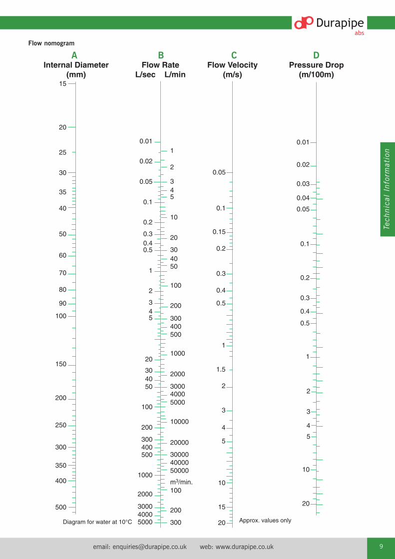
Flow calculationsPressure drop due to friction in pipesconveying water can be determined usingthe Flow Nomogram on page 9.
The pressure drop at a given flow rate canbe determined as follows:1. Obtain the internal diameter of the
pipe to be used by referring to thedimension table right:
2. Mark this diameter on Scale A.
3. Mark the required flow rate in litresper second on Scale B.
4. Draw a straight line connecting thepoints on Scales A and B and extendthis to Scales C and D.
5. The velocity of flow in metres persecond is determined from theintersection with Scale C.
6. The frictional head loss in metres per100 metres of pipe can then be readoff Scale D.
Technical Information
email: [email protected] web: www.durapipe.co.uk 9
Tech
nical Inform
ation
Flow nomogram
0.01
0.02
0.05
0.1
0.2
0.30.40.5
1
2
345
20
304050
100
200
300400500
1000
2000
300040005000 300
200
100
500004000030000
20000
10000
500040003000
2000
1000
500400300
200
100
504030
20
10
543
2
1
m3/min.
0.05
0.1
0.15
0.2
0.3
0.4
0.5
1
1.5
2
3
4
5
10
15
20
0.01
0.02
0.03
0.04
0.05
0.1
0.2
0.3
0.4
0.5
1
2
3
4
5
10
20
Pressure Drop(m/100m)
Flow Velocity(m/s)
Flow RateL/sec L/min
Internal Diameter(mm)
15
20
30
40
50
60
70
80
90
100
150
200
250
300
350
400
500
25
35
A B C D

Tel: +44 (0)1543 279909 Fax: +44 (0)1543 27945010
Fittings The calculation of pressure drop in fittings is more complex butcalculations can be made for equivalent lengths of straight pipeusing the formula E=F x D where:
E = equivalent pipe length (metres)F = fittings constant (see table below)D = fitting internal diameter (mm)
To calculate the total pressure drop in the system, the equivalentstraight pipe lengths for fittings is then added to the total straightpipe length to obtain the total drop.
Fittings constant90º elbow 0.0345º elbow 0.0190º tee - straight through 0.0190º tee - side branch 0.0690º bend 0.0145º bend 0.01Reducing bush (per size reduction) 0.015Butterfly valves 0.13Diaphragm valves 0.23Check valves 0.05
The values are included as a guide to aid calculation of overallsystem performance and should not be used in isolation.

email: [email protected] web: www.durapipe.co.uk 11
Tech
nical Inform
ation
Calculating expansion and contractionTemperature variations in a pipework system will increase ordecrease the length of each pipe. This is the result oftemperature changes in the fluid carried and also fromambient temperature variations.The rate of expansion or contraction of pipework is dependenton its length, its coefficient of expansion and the temperaturedifference.Increase/decrease in pipe length is given by the formula:
Expansion = L x � x �T
where: L = length (mm)� = coefficient of linear expansion �T = temperature difference of the pipe (ºC)
The coefficient of linear expansion for ABS: 10 x 10-5 per ºC
Rule of thumb: ABS expands/contracts 1mm/metre/10 ºCtemperature change:
Example:What is the expansion/contraction of an insulated, 30m long, ABS Condenser water main, installed at 15°C,operating at a maximum temperature of 35°C and a minimumtemperature of 5°C?
Expansion:L = 30,000 mm � = 10 x 10-5
�T = 35 - 15 = 20°C
Expansion = 30,000 x 10 x 10-5 x 20°C= 60mm
Contraction:L = 30,000 mm � = 10 x 10-5
�T = 15 - 5 = 10°C
Contraction = 30,000mm x 10 x 10-5 x 10°C= 30mm
Hence the system must be designed, using expansion loops,the natural flexibility of pipe, or expansion bellows, to cater fora differential movement, with an expansion of 60mm and acontraction of 30mm.
The system should be designed to cater for the greater amountof movement of either expansion or contraction.
Catering for pipe movementSystems installed above ground should be designed to ensure thatthere are sufficient changes in direction to accommodate expansionand contraction. The support method described later will ensure thatthe pipework can move axially without snaking. If sufficient changes in direction are not available within the designof the system, alternative methods of catering for pipe movementcan be considered such as expansion loops or flexible rubberbellows.
Expansion loopsThe length of unrestrained pipe (free leg length) required toaccommodate expansion can be calculated from the graph overleaf.
Pipemovement
Fixed point (anchor point)
Pipe clip
Pipe freeto flex
Anchor Point
A
B
?
30m
Pipe routingSystems installed above ground should be designed such thatthere are sufficient changes in direction to accommodateexpansion or contraction. The support method describedbelow will ensure that the pipework can move axially, withoutsnaking. Utilise all available pipe flexibility. Do not place clipstoo close to changes in direction.

Tel: +44 (0)1543 279909 Fax: +44 (0)1543 27945012
L2
H
H⁄2 max
L2
Example:Calculate the size of expansion loop required for a 90mm diameter pipe expanding 60mm andcontracting 30mm:Based on the worst case ie. 60mm expansion, �L = 30mm
2
Draw a horizontal line from the vertical section to meet the 90mm pipe gradient line. Drop a perpendicular from the intersection point to the horizontal scale. The figure obtained isthe free leg length of the loop required.Hence, in this instance a loop measuring 1400mm long x 700mm wide will cater for ±60mmmovement i.e. the loop will cater for both the expansion and contraction of the pipe.

email: [email protected] web: www.durapipe.co.uk 13
Tech
nical Inform
ation
Expansion bellowsBellows may also be used in place of or in conjunction with thenatural flexibility of the ABS. These must be approved for use bythe bellow manufacturers for use with thermoplastic pipework.Bellows must be installed in accordance with manufacturer’srecommendations.
Pipe supports and clipsPipe supports and clips should provide lateral restraint and allowfree, unrestricted, axial pipe movement. Standard ‘drop rods’ maynot provide sufficient lateral restraint and the ABS pipe could startto ‘snake’. Durapipe Cobra clips are designed to meet these requirements. A suitable alternative would be mild steel saddle clips designedwith a clearance between the pipe and the clip. All steel bracketsin contact with the plastic pipe should be free of sharp edges toavoid damaging the pipe.
Size Support Support Supportmm/imperial distance (m) distance (m) distance (m)
at 20°C at 50°C at 70°C16mm / 3⁄8" 0.8 0.5 0.420mm / 1⁄2" 0.9 0.6 0.525mm / 3⁄4" 1.0 0.7 0.632mm / 1" 1.1 0.8 0.740mm / 11⁄4" 1.2 0.9 0.750mm / 11⁄2" 1.3 1.0 0.763mm / 2" 1.4 1.1 0.875mm / 21⁄2" 1.5 1.2 0.890mm / 3" 1.6 1.2 0.9
110mm / 4" 1.8 1.3 1.0125mm 1.9 1.4 1.0140mm / 5" 2.0 1.5 1.1160mm / 6" 2.1 1.6 1.2200mm 2.2 1.7 1.3225mm / 8" 2.3 1.8 1.5250mm 2.5 2.0 1.7
10" 2.7 2.2 1.9315mm / 12" 2.9 2.4 2.1
Support centresThe recommended distance between supports for ABS pipes filledwith water is given in the table below. This table is based on thethinnest wall pipe in each size. For sizes 1", 11/4", 11/2", 2", 3" and4" the support distance can be increased by 10% for class E pipes.Where the contents have a specific gravity greater than 1, thedistance must be decreased by dividing the recommended centredistances by the specific gravity. The details shown are forhorizontal pipes. For vertical pipes, support centres may beincreased by 50%.
Pipe trays are available for sizes 16mm, 20mm, 25mm and32mm (see page 69). These allow support distances to beincreased to 2.0 metres.
Anchor pointsThe direction of pipe movement can be controlled by the use ofanchor points at strategic positions. There are a number ofmethods of securely anchoring plastic pipes, some of which aredetailed below. However it should be noted that tight fitting pipesupports should not be used since damage to the pipe could occur.Note: See above for advice on anchoring of bellows.
Construction of typical anchor points
1. Small Bore (up to 4" Pipework)
2. Larger pipe (above 4" Pipework)

Tel: +44 (0)1543 279909 Fax: +44 (0)1543 27945014
Recommendations covering essential requirements for installations below ground may be summarised as follows:In general, trenches should not be less than a metre deep.Trenches should be straight sided, approximately 300mm wider than the pipe diameter to allow proper consolidation ofpacking materials.Trench bottoms should be as level as is practical.Large pieces of rock, debris and sharp objects should be removed.Alternatively gravel can be laid approximately 100mm deep on thefloor of the trench. (Sand may be used but subterranean water isliable to wash sand away and leave the pipe unsupported.)If pipes are jointed above ground, they should remain undisturbedfor 2 hours before being lowered into the trench.After laying, pipes should be covered with gravel or similar materialto a depth of 100mm above the crown of the pipe. The gravelshould be extended sideways to both trench walls and compacted.This should be done prior to testing, with joints left exposed.Care should be taken to ensure that sharp objects, stones, etc, areprevented from falling into the trench before covering the pipe.After pressure testing, joints should be covered with gravel orsimilar material, and back filling completed.A section of pipe installed below ground to the aboverecommendations is shown in the illustration.
Anchor blocksFor wholly solvent welded systems the pipework is pressurebalanced and anchor thrust blocks are not required. When rubber ring joints are used it is necessary to provide concreteanchor blocks at all sudden changes in direction such as elbows,bends, tees etc. This is necessary to withstand the forces generatedby system pressurisation.For greater detail, users in the U.K. are recommended to study theCode of Practice CP 312 published by the Pipe and Fittings Groupof the British Standards Institute covering installations above andbelow ground.
Buried pipesSupport of heavy equipmentLarge valves, strainers and other heavy equipmentshould always be independently supported to preventundue loading onto the ABS system. Durapipe valvesupport plates have been designed for this purposeand may be used in place of flange backing rings.

email: [email protected] web: www.durapipe.co.uk 15
Tech
nical Inform
ation
Thermal insulationSome insulation products can contain substances capable of havinga detrimental effect on thermoplastic pipework eg. certain types offoam rubber insulations can cause pipes to fail where the ABS isconveying liquids at temperatures above 30°C.
Recommended insulation - a list of some of the common types ofinsulation materials known to be suitable with ABS pipework are as follows:Fibre wool, such as ‘Rockwool’Armaflex Class 1 HTKoolphen K Phenolic foamPolystyreneNote - the above list is not exhaustive – please contact ourTechnical Support Department if further assistance is required.
Some adhesives can also be detrimental. Do not bond insulation toABS. (This comment also applies to any tapes, adhesives, or othersubstances used to secure the heating tape to the pipework.)
Trace heating tapesThe selection of heating tapes with silicone rubber, woven wire or woven polyester outer sheaths will eliminate the risk ofplasticiser migration. These tapes are therefore preferred for use on thermoplastic systems.
Pipe contents identificationDo not put self-adhesive labels directly on to pipe surfaces as thismay be detrimental to pipe performance. It is recommended thatsome sort of barrier, such as aluminium foil, is placed between pipeand identification label.
Intumescent mastic and mastic sealantsCertain mastic sealants are formulated with phthalates. Phthalatesare known to be extremely aggressive toward ABS materials, andtherefore confirmation of the suitability of any mastic sealantshould be determined before being used in conjunction with ABS pipework.
Pipe clipsIt is important that the composition of pipe clips and their liningsdo not include substances which might have a detrimental effectupon the ABS pipe. Please check for suitability before use.We strongly recommend the use of Durapipe Cobra clips for pipesizes up to and including 160mm OD / 6"NB, wherevercircumstances allow.
Pneumatic testingPneumatic testing is not recommended because of the risk topersonnel or property if, for example, a joint has beentemporarily assembled without solvent cement and has thenbeen mistakenly left in that condition. Such joints could separatesuddenly and violently during the test.Also, leak detection sprays designed to detect air leaks on steelpipework can damage thermoplastics.
Contact with synthetic oilsSome synthetic oils are unsuitable for use with thermoplastic pipesystems. The main types of synthetic oils identified as beingincompatible with thermoplastic pipe systems includes Esters,Polyalkylene Glycols and Organic Phosphates.
Freezing conditionsPrecautions should be taken to prevent contents freezing, as thiscan cause pipework to split.
Mono-ethylene glycol can be added to the system to lower thefreezing point. See opposite for advice on insulation and traceheating.
Contact with fluxesSome fluxes can be detrimental to ABS. Care should be taken when soldering copper pipework directly above, or close to, ABS pipework.
Buried pipesDo not lay ABS in contaminated ground eg. ‘brown-field’ sites. Do not lay ABS in ground where spillages of chemicals may occur.
Thread sealantsSome thread sealants can damage ABS. PTFE tape should be usedwhen making threaded connections. See page 21 for furtherinformation.
Resistance to U.V. (sunlight)Care should be taken to avoid exposure to U.V. light, e.g. sunlight,particularly during storage. This will cause discoloration anddeterioration of the ABS material. Whilst this is a surface effectonly it is recommended that precautions be taken to prevent thishappening. If stored outdoors pipe should be covered with opaquesheeting. If installed outdoors it can be protected from the effects ofU.V. by insulating or painting.
Pressure surgesDurapipe ABS pipework can withstand pressure surges within thelimitations detailed within CP312 Part 2:1973 and its amendmentdated 1977.On no account should pressure surges be allowed to exceed themaximum continuous working pressure calculated using the graphon page 8.
Additional Important Information

Tel: +44 (0)1543 279909 Fax: +44 (0)1543 27945016
Durapipe ABS Jointing Guide
Solvent cement welding offers a simple and quick means ofconstructing high integrity, leak-free joints.
The solvent cement operates by chemically softening the jointsurfaces. Joint integrity will be greatly reduced if these surfaces arenot clean and properly prepared.
Durapipe ABS solvent cement must be used. The jointing procedure detailed below must be followed.
This relates to the new ‘one-step’ solvent cement. With this cementit is not necessary to abrade pipe or fitting (unless making a jointon to old ABS pipe).
No attempt should be made to increase the clearance between thepipes and fittings.
Procedure1. The pipe must be cut clean and square. A suitable wheel cutter
will eliminate swarf. As an alternative (and on larger sizes) acarpenters saw should be used, however this may create dustand swarf which can enter the system.
2. Chamfer the end of the pipe using a coarse file or suitablechamfering tool. The chamfer should be approximately 45° by3mm to 5mm depending on the pipe size. Reducing bushesshould also be chamfered (unless where a moulded chamfer isincluded).
3. Mark the pipe a known distance from the end and clear of thearea to be cleaned. This mark should be used to confirm fullinsertion of pipe into socket of fitting.
4. Ensure joint surfaces are clean and free from moisture. Clean surfaces thoroughly with Durapipe Eco-cleaner using lintfree cloth/paper towel.
5. Using a clean brush apply cement to the pipe and fitting. Thejoint surfaces should be completely covered by cement.
Cement should be applied using an appropriate size brush andtin of cement. It is important to apply cement quickly to enableassembly without excessive force being required.When applying cement with brush, the size of the brush shouldbe approximately half the size of the pipe to be jointed - brushsize up to 21/2" (63mm) for 0.5 litre and up to 3" (75mm) for 1 litre tins.

email: [email protected] web: www.durapipe.co.uk 17
Tech
nical Inform
ation
6. Immediately after applications of cement, push pipe fully homeinto the fitting. Do not twist. Hold the pipe and the fitting fortimes varying from a few seconds on sizes 3/8" or 16mm up to1 minute on sizes 12" or 315mm. The slight taper mouldedinto the fitting may otherwise cause it to slide off the pipe withconsequent loss of joint strength. Application of the correctamount of cement will result in a neat bead of cement at theedge of the fitting and at the edge of the pipe. Excessivedeposits inside the fittings must be avoided as these canweaken the wall, particularly on smaller sizes. When working under cold conditions make sure the joints arefree from frost and moisture.
7. Wipe off excess cement from the outside of the joint.
8. Using the mark previously made, check that the pipe has beenfully inserted.
9. Do not disturb a joint for least 10 minutes. On larger sizes donot subject the joint to bending or twisting forces for at least 4 hours. When making subsequent joints, which can be donewithout waiting, take care not to transmit forces to freshly madejoints in the system.
10. Replace lids on containers.
CAUTION• DO NOT use near naked flames
• DO NOT smoke in the working area
• DO NOT use in confined spaces
• DO NOT joint in the rain or wet conditions
• DO NOT use dirty brushes
• DO NOT use dirty or oily cleaning cloths
• DO NOT use the same brushes for different cements
• DO NOT dilute or decant Durapipe ABS solvent cement
• Follow safety instructions on Durapipe solvent cement and Eco-cleaner containers
• Always wear appropriate personal protective equipment
Notes1. The integrity of Durapipe ABS systems may be affected if
Durapipe ABS One-step solvent cement and Durapipe Eco-cleaner are not used.
Durapipe UK disclaims responsibility for any Durapipe ABSsystem constructed with any other cement or not fabricated inaccordance with the instructions herein.
2. Use the appropriate size of solvent cement tin/container and method of application for the size of pipe and fitting to be assembled.
3. To achieve the correct speed of application on sizes 5"/140mmand above, cement should be applied simultaneously to pipeand fitting, by two people.

Tel: +44 (0)1543 279909 Fax: +44 (0)1543 27945018
Size Range Up to 21/2" 3" to 4" 5" & 6" 8" 10" & 12"75mm 90mm to 125mm 140mm & 160mm 200mm & 225mm 250mm & 315mm
Drying Time 0.5 hour / bar 1.0 hour / bar 1.5 hours / bar 2.0 hours / bar 48 hours minimum
Note - minimum drying period should never be less than 1 hour.
Drying timesThe drying times will vary with fit, amount of solvent cementapplied, ambient temperature and working pressure. It isrecommended that, wherever possible, joints of sizes up to8"/225mm are allowed to dry for at least 24 hours, and sizes 10"and 12"/250mm and 315mm for at least 48 hours. These guidelines are based on an ambient temperature ofbetween 10°C to 40°C. Longer drying times will be required atlower and higher ambient temperatures.
It is recognised that there will be occasions when the system willneed to be put into service within a few hours of being made. A rough but safe working guide where the ambient temperature is between 10°C to 40°C and the contents temperature does notexceed 20°C is as follows:
Size Recommended Joints per litremm inch container size ABS
16 - 32 3/8 - 1 0.5 Litre 40040 - 63 11/4 - 2 0.5 Litre 20075 - 110 21/2 - 4 0.5 Litre 70125 - 140 5 1 Litre 20160 - 225 6 - 8 1 Litre 10250 - 315 10 - 12 1 Litre 5
An indication of the number of joints to be made per litre ofcement is as follows:

email: [email protected] web: www.durapipe.co.uk 19
Tech
nical Inform
ation
Branch connections - reduced boreReduced branch connections can be made as follows:
Imperial range:Bushed equal tees or Y-Pieces, solvent cemented saddles.
Metric range:Bushed equal tees or Y-Pieces, reduced branch tees.
Saddles permit branch connections to be made with the main pipein situ. The following procedure must be followed carefully:
1. After making sure that the pipe is empty, drill a hole in the pipewall to suit the connection. The size of hole and cutter to beused for each size of saddle is indicated below:
Pipe size Hole diameter Cutter size(Imperial) (mm) (Imperial)
2 48 17/83 61 23/84 74 27/86 74 27/8
2. Mark out the area covered by the saddle on the pipe.
3. Clean surfaces with Eco-cleaner.
4. Feed on to pipe two worm drive (Jubilee) clips which willclamp the saddle during fitting. These should be placed eitherside of the socket on the saddles. Apply cement to pipe areaand saddle. It is important to apply cement quickly.
5. Position saddle immediately, ensuring that spigot locates in hole in pipe wall. Clamp in place using worm drive clipswithout delay.
6. Wipe off any excess cement.
7. Replace lids on containers. 8. Clean brush with Eco-cleaner.
Important:1. See page 18 for details of drying times. Allow 24 hours before
removing straps.2. On no account should a branch tee be constructed by drilling
through the wall of a pipe and/or fitting and attempting tosolvent weld a smaller fitting into the hole.

Tel: +44 (0)1543 279909 Fax: +44 (0)1543 27945020
Reducing bushesReducing bushes offer a neat and simple method of reducingsocket size in the minimum of space.Care must be taken to properly prepare all jointing surfaces asrecommended earlier, with the end of the bush being chamfered(unless a moulded chamfer is included).
Example in the use of reducing bushes
The use of reducersAll fittings have female ends, dimensionally controlled for coldfusion jointing. In addition, reducing sockets in the Metric serieshave controlled outside diameter at the larger end. This allows useas a male or female component, as illustrated.
Metric series threaded adaptorsFemale and male threaded adaptors have controlled inside andoutside diameters on the plain end. They can therefore be used as a male or female component.
The use of bushes, reducers and threaded adaptors
110mm tee
90 x 75
110 x 90
25 x 20 x 16 reducer
16mm pipe
20mm pipe
25mm socket
25 x 20 x 16 reducer
16mm pipe

email: [email protected] web: www.durapipe.co.uk 21
Tech
nical Inform
ation
Flanged jointsFull face flanges are available from 1/2" to 6".Stub flanges are available from 2" to 12" and in metric sizes from16mm to 315mm and provide a convenient means of convertingfrom Imperial to Metric systems in sizes 8"/200mm and above.The correct galvanised mild steel backing ring and rubber gasketmust be used with both types.
Flange bolting procedureThe following procedure is recommended for installing DurapipeABS flanges:1. Inspect flange faces and ensure that they are clean and
undamaged.2. Check that the correct backing ring and rubber gaskets have
been supplied. Durapipe supplies a matched system of flangesand backing rings - do not interchange Metric and Imperialcomponents.
3. Loosely assemble flanges. Ensure that flanges and bolt holesalign and that the flange faces are parallel. Ensure that thegasket is correctly positioned between the flanges.
4. Ensure that the appropriate sized washer is placed under bothbolt heads and nuts.
5. Tighten the nuts and bolts in a diagonally opposite sequence(see below) to ensure even loading around the flange to avoiddistortion. It is recommended that the nuts and bolts betightened as uniformly as possible progressively from a fingertight start.
6. Repeat as necessary until tightness of all bolts is achieved.
Connections - plastics to metal There are several recommended methods to connect metal andplastic systems:Composite unionsFlangesMale threaded fittingsFemale threaded fittings
Plastics expand or contract more than metals for any given changein temperature. The practice of connecting plastic threaded fittingsto metal threads is not recommended where the joint is likely toexperience a temperature change of more than +/-5ºC, otherwiseleaks may occur.Composite unions are available with brass male or female BSP threaded adaptors.
Tightening torques for flangebolts in ABS piping systems
Recommended Torque Values (Nm)
1
2
3 4
5
67
8
1
2
3 4
5
6
7
8
11
912
10
1
2
3 4
The tolerance on torque is +/-10%
Size Torque16 1520 1525 1532 1540 2050 3063 3575 4090 40110 40125 50140 50160 60200 70225 70250 80315 100
Tightening sequence
If it is required to cut a thread on to Durapipe ABS pipe, use asharp die especially reserved for plastic pipes and cut full threaddepth without lubricant, in one operation.This should only be attempted on pipe sizes up to 2" n.b. Class Tpipe must be used. Pipes from Durapipe ABS metric range are notsuitable for threading.Assembly should be carried out by hand and final tightening by astrap wrench, if necessary.Extra care must be taken not to overtighten or damage the thread.Pipe wrenches must not be used.It is recommended that PTFE tape be used when making threadedjoints/connections. Any other sealing compound must be confirmed by Durapipe asbeing suitable.‘Boss White’ and anaerobic adhesive sealants, such as Loctite 542and 572, can chemically attack ABS and must not be used.
Connection to instrumentationInstrumentation connections can be made by drilling through pipeand socket where the material is at its thickest and tapping thehole to receive a threaded fitting, as shown below:
Pipe size Connection size16mm-63mm/3⁄8"-2" Use tees, reducing bushes and
threaded fittings75mm-110mm/21⁄2"-4" Max. tapping 1⁄2" BSP.125mm-140mm/5" Max. tapping 3⁄4" BSP.160mm & above/6" & above Max. tapping 1" BSP.
Such connections, if correctly drilled and tapped with full threadform will be limited to Class C/PN10 pressures.
Instrument connection
Threaded connections

Tel: +44 (0)1543 279909 Fax: +44 (0)1543 27945022
Chemical Resistance Typical Unsuitable for the Sizes and jointingand Performance Data applications following uses information
Moderately strong mineral acids Chilled water Applications over 70ºC Metric: 16mm to 315mm OD
Caustic and ammoniacal solutions Low temperature brine Bleaches Imperial: 3/8" to 12" NB
Most inorganic salt solutions Potable water Solvents Jointed by solvent cement welding
Some detergents Process water Domestic hot water Threaded fittings available
Temperature range -40ºC to +70ºC Flammable substances
Properties guide
Tabulated below is a comparison of imperial and metric sizedDurapipe ABS pipe. They are produced to different standards, butcan be joined together using flanges or adaptors.
The systems are also designated differently; the imperial systemrefers to the nominal bore size; the metric system relates to theoutside diameter.
Both systems are produced with the outside diameter as thecontrolled dimension. This enables the same fitting of a particularsize to be joined to all classes of pipe in that size.
Please refer to the pipe section in this brochure for pipe sizes available from Durapipe UK.
Threaded systemsImperial systems Class T ABS pipe can be machined to BSPparallel or BSP taper thread forms. Metric pipe is not producedwith an outside diameter suitable for threading.
Comparison of ABS Imperial and Metric Sized Pipe
3/8 17.0 1.6 3.4 16 16.0 1.41/2 21.2 1.9 3.5 20 20.0 1.53/4 26.6 2.4 3.5 25 25.0 1.81 33.4 1.9 3.0 4.2 32 32.0 2.011/4 42.1 2.4 3.8 5.1 40 40.0 2.511/2 48.1 2.7 4.4 5.8 50 50.0 3.22 60.2 3.4 5.4 7.0 63 63.0 4.021/2 75.0 4.7 75 75.0 4.73 88.7 5.0 8.06 90 90.0 5.74 114.1 6.4 10.3 110 110.0 6.9
125 125.0 7.95 140.0 8.8 140 140.0 8.86 168.0 9.4 12.3 160 160.0 10.0
200 200.0 12.58 218.0 12.2 225 225.0 14.1
10 272.6 10.5 250 250.0 15.612 323.4 12.4 315 315.0 19.7*
21/2" and 5" pipes are PN10 rated.*315mm is rated at PN8.
Size Minimum mean Minimum wall thickness (mm) Size Minimum mean Minimum wall (nominal bore) outside diameter outside diameter outside diameter thickness (mm)
(imperial) (mm) Class B Class C Class D Class E Class T (mm) (mm) PN10
Imperial System (BS 5391) Metric System (ISO 15493)
Note: Temperatures given are for guidance only, please check before specifying.

email: [email protected] web: www.durapipe.co.uk 23
Tech
nical Inform
ation
Handling and storageThe high impact strength of Durapipe ABS systems provides someprotection against damage but care should be taken at all stages ofhandling, transportation and storage.
Pipe must be transported by a suitable vehicle and properly loaded and unloaded, e.g. wherever possible moved by hand ormechanical lifting equipment. It must not be dragged across the ground.
The storage should be flat, level and free from sharp stones.
LengthsPipe lengths stored individually should be stacked in a pyramid notmore than one metre high, with the bottom layer fully restrained bywedges. Where possible, the bottom layer of pipes should be laidon timber battens at one-metre centres. On-site, pipes may be laidout individually in strings. (Where appropriate, protective barriersshould be placed with adequate warning signs and lamps.)
General Information
BundlesBundled packs of pipe should be stored on clear, level ground withthe battens supported from the outside by timbers or concreteblocks. For safety, bundled packs should not be stacked more thanthree metres high.Smaller pipes may be nested inside larger pipes. Side bracingshould be provided to prevent stack collapse.
Similar precautions should be taken with fittings and these shouldbe kept in protective wrappings until required for use.

Tel: +44 (0)1543 279909 Fax: +44 (0)1543 27945024
Health and Safety at Work Act and COSHH RegulationsAttention is drawn to the requirements in the UK of this Act and to the Control of Substances Hazardous to Health (COSHH)Regulations. Durapipe UK cannot accept responsibility for accidentsarising from the misuse of its products because of bad installationor incorrect application.
Material safety dataMaterial Safety Data sheets are available on our website.
Filling and flushingWhen purchasing chemicals for either flushing or long-term system use, suppliers should be advised that this is for ABSmaterial. Guidance on the suitability of various system flushing or filling fluids with ABS can be found in the Durapipe ChemicalData catalogue, 04900004.
TestingIt is suggested that the following test procedure be followed, afterjoints have been allowed to dry for the appropriate minimum time(at least 24 hours up to 8"/225mm, sizes 10"/250mm and12"/315mm require a minimum of 48 hours at 20°C).The system should be divided conveniently into test sections.Fill section with cold water making sure that no air pockets remain. Do not pressurise at this stage.Check system for leaks. If none are apparent, check for and removeany remaining air. Increase pressure up to 3bar. Do not pressurisefurther at this stage.Leave section pressurised for 10 minutes. If pressure decays,inspect for leaks and rectify as necessary. If pressure remainsconstant, slowly increase the hydrostatic pressure to 11/2 timesnominal operating pressure.Leave section pressurised for a period not exceeding 1 hour. During this time pressure should not change.
CautionPersonnel must stand well clear when pressure testing systems. Note: If extended times are required to achieve hydrostaticpressure, either leakage has occurred or air remains in the line.Inspect for leakage and if none is apparent, reduce pressure andcheck for trapped air. This must be removed before furtherpressurisation commences.
ColourDurapipe ABS products are a mid-grey colour, generally inaccordance with BS5252, colour ref. 18 B 21 and RAL 7001.
Auto CAD drawingsTwo dimensional drawings of Imperial and Metric productscontained in this brochure are available on our websitewww.durapipe.co.uk. Available in Fastrack format.
ABS dimensions and standardsImperialThe Durapipe ABS Imperial System is manufactured in accordancewith the relevant British Standards as shown below. Kitemarklicences are also held, where applicable, for both pipes and fittings.BS 5391 (pipe) BS 5392 (fittings).
MetricThe Durapipe ABS Metric System is manufactured generally inaccordance with the relevant international standards as shownbelow:ISO 15493KIWA 49 and 549DIN 8062 and 8063
Threaded fittings conform to the requirements of BS 21/DIN2999/ISO7. Socket dimensions of Durapipe ABS Metric fittings forsolvent welding comply with ISO/DIS 727-1.
MaterialsDurapipe ABS material is UK Water Regulations Advisory Scheme approved for cold water services and is listed in the Water Fittings and Materials Directory.Durapipe ABS formulation does not contain any harmful metallic stabilisers.
Gaskets and sealsGaskets and O-Ring seals are made from EPDM except wherestated otherwise.
InterchangeabilityComponents in the imperial and metric ranges are notinterchangeable, except for 21/2"/ 75mm and 5"/140mm.
ApprovalsDurapipe ABS Imperial series pipe is covered by Kitemark Licence No. KM07961 to BS 5391:Part 1 1976.Durapipe ABS Imperial series fittings are covered by Kitemark LicenceNo. KM07962 to BS 5392:Part 1 1976. Durapipe ABS Imperial series pipe and fittings are UK WaterRegulations Advisory Scheme approved for cold water services. Durapipe ABS Metric series pipe and fittings are UK Water RegulationsAdvisory Scheme approved for cold water services.Durapipe ABS one-step solvent cement is UK Water RegulationsAdvisory Scheme approved. Durapipe Metric pipework is approved for various non-essentialservices on board ships by:Lloyds Register of ShippingDet Norske VeritasBureau VeritasAmerican Bureau of ShippingGermanischer Lloyd

email: [email protected] web: www.durapipe.co.uk 25
Tech
nical Inform
ation
AbbreviationsThe following list of abbreviations is used in this catalogue:ABS - Acrylonitrile Butadiene StyreneBS - British StandardsISO - International Standards OrganisationDIN - Deutsche Industrie Normen (German Industrial Standards)KIWA - Keuringsinstituut Voor Waterleidingartikelen (Netherlands)ANSI - American National Standards InstituteBSP - British Standard Pipe ThreadEPDM - Ethylene Propylene RubberFPM - Fluorine Rubber (e.g. Viton®)PTFE - Polytetraflouroethylene (eg Teflon®)® Dupont registered trade name.
Ordering by codeCode numbers should be used when ordering products e.g.
Imperial
Metric
Mechanical, Physical and Electrical Data Test Method Value
Mechanical
Tensile strength at yield (23ºC) ASTM D635 45MN/m2
Tensile modulus of elasticity ASTM D635 2200MN/m2
Poissons ratio - 0.35
Izod impact strength at 23ºC (notched) ASTM D256 (1/8") 35kJ/m2
Charpy impact strength at 23ºC (notched) - 20kJ/m2
Physical
Specific gravity ASTM D792 1.04
Softening point (BS2782:Part 1 Method120B:1976) ISO R 306 (5kg) (heating rate unknown) 99ºC
Linear co-efficient of thermal expansion - 10.1 x 10⁻⁵/ºC
ISO75 HDT/Ae 1.8Mpa ASTM D648 (unannealed, 1/4", 18.56 Kgf/cm2) 78ºC
Thermal conductivity - 0.157W/mºC
Specific heat - 2.1kJ/kg.K
Self ignition temperature - 540ºC
Electrical
Dielectric constant - 2.9 at 103Hz
2.8 at 106Hz
Volume resistivity IEC 93 - >1.E14ohm m
Range Shape Size
ABS Tee 3"
12201 109Code
Range Shape Size
ABS Tee 90mm
122 31311
Code

Tel: +44 (0)1543 279909 Fax: +44 (0)1543 27945026
Product SpecificationIMPERIAL RANGEDURAPIPE ABS PIPESIn accordance with the dimensional and testing requirements of BS 5391 Third Party Approved with British Standard Kitemark Licence (where applicable).
DURAPIPE ABS FITTINGSIn accordance with the dimensional and testing requirements of BS 5392 Third Party Approved with British Standard Kitemark Licence (where applicable).
MATCHED SYSTEMThe ABS products (see below) shall be from a single manufacturer to ensurecomplete integrity, quality and compatibility between pipes, fittings and valves.Manufacturers warranties may be compromised if a system is installed withmaterials from various manufacturers. Where this is not possible then anyalternative products should be confirmed as being at least equivalent to that whichis normally supplied.
QUALITY SYSTEMPipes, fittings and valves shall be manufactured in an environment, which operatesa Quality Assurance System assessed to ISO 9001.
ENVIRONMENTAL SYSTEMThe manufacturer of pipes, fittings and valves shall be able to demonstratecompliance with applicable environmental legislation and products shall bemanufactured in an environment where documented performance reviews areundertaken and an Environmental Management System is successfully assessed to ISO 14001.The manufacturer shall offer ABS solvent cements and cleaners, specially formulated to minimise any adverse effects on the environment during installation of the ABS system.
THIRD PARTY APPROVALSThe manufacturer shall have the following Third Party Approvals:
British Standard Kitemark LicenceKM07961 for Durapipe Inch pipes to BS 5391KM07962 for Durapipe Inch fittings to BS 5392
WRAS Water Regulations Advisory Scheme0605104 for Durapipe Inch pipes & fittings (1100)0702501 for Durapipe one-step solvent cement (5560)
Department of the EnvironmentM & E 100 Standard Specification for Air Conditioning
Department of Health and Social SecurityRenal Dialysis Applications
APPROVAL FOR USE IN CONTACT WITH DRINKING WATERAll ABS pipes, fittings and solvent cement shall be listed in the Water Fittings and Materials Directory to show compliance with the requirements of the UnitedKingdom Water Regulations Advisory Service.Copies of certification of compliance with these approvals are available for inspection.
DESIGN LIFEPipes, fittings and valves shall be designed to operate continuously for 50 years attheir maximum rated pressure at a working temperature of 20°C.Process Control Testing must be carried out during manufacture and documented oneach and every production batch.Fittings and Pipes will be subjected to a pressure test of 3.2 x maximumrecommended working pressure for 1 hour at 20°C during 1st and 2nd hours ofproduction, then every 6 hours for fittings, and 8 hours for pipes.Pipes are in addition to be impact tested after conditioning at 0°C for 1 hour.Fittings are in addition to be subject to stress relief testing at 150°C.Pipes and fittings shall undergo dimensional, marking and visual inspection at thefrequency outlined above.
CHEMICAL SUITABILITY The manufacturer shall publish detailed chemical resistance data to enable thesuitability of the ABS material, seals and gaskets to be determined by designers and specifiers. The manufacturer shall also employ a qualified and experienced chemist and provide a free-of-charge service advisory service for assessing the suitability of itsABS material, seals and gaskets.
INSTALLATION SPECIFICATIONThe installation must be carried out by competent persons. The contractor shall be required to provide technical documentation relating to themanufacturers recommended Installation procedures.The manufacturer shall publish Installation recommendations, and shall also providea free-of-charge training service for designers and installers, with appropriate writtenconfirmation of attendance.
DURAPIPE ABS BALL VALVESTrue union design, end load resistant with full pressure and shock resistant anti blowout device which conforms to design and endurance testing requirements of BS 5392 Part 1 1976, and DIN 3230 Part 3 Leak Rate One (Water and Air). The following testing will have been successfully conducted:Drop Tight and Bubble Tight test.Hydrostatic Shell Test 1.5 x Maximum Working Pressure.Seat Test 1.1 x Maximum Working Pressure.
PRESSURE RATINGUp to size 2" - PN15 (Class E) at 20°C (VKD series), PN10 (EV series)21/2" to 4" - PN15 at 20°C (VKD series)
SEATS AND SEALSSeats: PTFE material fitted with O-Ring compensators. Seals: Standard size O-Ring type for ease of replacement. Available in EPDM or FPM materials.
END CONNECTIONSPlain socket ends, or BSP threaded.
ACTUATIONOptions: Electric or pneumatic.
DURAPIPE ABS DIAPHRAGM VALVESEquipped with a maintenance free hand wheel actuator with spindle extension toindicate the position of the valve open or closed. The body retaining bolts are fixedfrom the underside, to provide a crevice free outer surface to prevent accumulationof debris or risk of corrosion of exposed steel bolts from chemical spillage.
Valves will have been hydrostatically pressure tested to the requirements of BS 5392 Part 1 1976, BS 5156, ISO 7508 and DIN 3230 Part 3 Leak Rate One.
PRESSURE RATING1/2" to 4" - PN10 at 20°C
DIAPHRAGM TYPEChoice of EPDM, FPM or PTFE will be available.
END CONNECTIONThese may be plain spigot ends or flanged.
ACTUATIONOptions: Pneumatic
DURAPIPE ABS BALL CHECK VALVESThese shall be double union with plain socket or BSP threaded ends.
PRESSURE RATING1/2" to 2" - PN10 at 20°C.
SEALSAvailable in either EPDM or FPM.
DURAPIPE ABS BUTTERFLY VALVESReinforced Polypropylene body, fully lined, with ABS disc.Full flanged design, with oval holes/inserts to suit various standard flange drillings.Lever operated, with 10 x 10° position stops, and locking device.
PRESSURE RATING11/2" to 10" - PN10 at 20°C12" - PN8 at 20°C
PRIMARY LINERAvailable in EPDM, FPM, or NBR.
ACTUATIONElectric, Pneumatic, or Gearbox (standard on sizes over 8").

email: [email protected] web: www.durapipe.co.uk 27
Tech
nical Inform
ation
METRIC RANGEDURAPIPE ABS PIPESKIWA 49, ISO 161/1, and ISO DIS 15493 (where applicable). Pressure rating PN10 at 20°C up to 250 mm. PN8 at 20°C for 315 mm.
DURAPIPE ABS FITTINGSKIWA 549, ISO 727 and ISO DIS 15493 (where applicable). Pressure rating PN10 at 20°C up to 250 mm. PN8 at 20°C for 315 mm.
MATCHED SYSTEMThe ABS products shall be from a single manufacturer to ensure complete integrity,quality and compatibility between pipes, fittings and valves. Manufacturerswarranties may be compromised if a system is installed with materials from variousmanufacturers. Where this is not possible then any alternative products should beconfirmed as being at least equivalent to that which is normally supplied.
QUALITY SYSTEMPipes, fittings and valves shall be manufactured in an environment which operates aQuality Assurance System assessed to ISO 9001.
ENVIRONMENTAL SYSTEMThe manufacturer of pipes, fittings, and valves shall be able to demonstratecompliance with applicable environmental legislation and products shall bemanufactured in an environment where documented performance reviews areundertaken and an Environmental Management System is successfully assessed to ISO 14001.The manufacturer shall offer ABS solvent cements and cleaners, specially formulated to minimise any adverse effects on the environment during installation of the ABS system.
THIRD PARTY APPROVALSThe manufacturer shall have the following Third Party Approvals:
WRAS Water Regulations Advisory Scheme0510074 for Durapipe Metric pipes and fittings0702501 for Durapipe one-step solvent cement (5560)
DEPARTMENT OF HEALTH AND SOCIAL SECURITYRenal Dialysis Applications
DET NORSKE VERITAS
BUREAU VERITAS
APPROVAL FOR USE IN CONTACT WITH DRINKING WATERAll ABS pipes, fittings and solvent cement shall be listed in the Water Fittings and Materials Directory to show compliance with the requirements of the UnitedKingdom Water Regulations Advisory Service.Copies of certification of compliance with these approvals are available for inspection.
DESIGN LIFEPipes, fittings and valves shall be designed to operate continuously for 50 years attheir maximum rated pressure at a working temperature of 20°C.Process Control Testing must be carried out during manufacture and documented oneach and every production batch.Fittings and Pipes will be subjected to a pressure test of 3.2 x maximumrecommended working pressure for 1 hour at 20°C during 1st and 2nd hours ofproduction, then every 6 hours for fittings and 8 hours for pipes.Pipes are in addition to be impact tested after conditioning at 0°C for 1 hour.Fittings are in addition to be subject to stress relief testing at 150°C.Pipes and fittings shall undergo dimensional, marking, and visual inspection at thefrequency outlined above.
CHEMICAL SUITABILITYThe manufacturer shall publish detailed chemical resistance data to enable thesuitability of the ABS material, seals, and gaskets to be determined by designers and specifiers.The manufacturer shall also employ a qualified and experienced Chemist andprovide a free-of-charge advisory service for assessing the suitability of its ABS material, seals, and gaskets.
INSTALLATION SPECIFICATIONThe installation must be carried out by competent persons. The contractor shall be required to provide technical documentation relating to themanufacturers recommended Installation procedures. The manufacturer shall publish Installation recommendations, and shall also providea free-of-charge training service for designers and installers, with appropriate writtenconfirmation of attendance.
DURAPIPE ABS BALL VALVESTrue union design, end load resistant with full pressure and shock resistant anti blowout device which conforms to design and endurance testing requirements of BS 5392 Part 1 1976, and DIN 3230 Part 3 Leak Rate One (Water and Air).
The following testing will have been successfully completed:
Drop Tight and Bubble Tight test.Hydrostatic Shell Test 1.5 x maximum working pressureSeat Test 1.1 x maximum working pressure.
PRESSURE RATING16mm to 63mm - PN 16 at 20°C (VKD series), PN10 (EV series)75mm to 110mm - PN16 at 20°C (VKD series)
SEATS AND SEALSSeats: PTFE material fitted with O-Ring compensators. Seals: Standard size O-Ring type for ease of replacement. Available in EPDM or FPM materials.
END CONNECTIONSPlain socket ends or BSP threaded.
ACTUATIONOptions: Electric or Pneumatic.
DURAPIPE ABS DIAPHRAGM VALVESEquipped with a maintenance free hand wheel actuator with spindle extension toindicate the position of the valve open or closed. The body retaining bolts are fixedfrom the underside, to provide a crevice free outer surface to prevent accumulationof debris or risk of corrosion of exposed steel bolts from chemical spillage.
Valves will have been hydrostatically pressure tested to the requirements of BS 5392 Part 1 1976, BS 5156, ISO 7508 and DIN 3230 Part 3 Leak Rate One.
PRESSURE RATING20mm to 110mm - PN10 at 20°C
DIAPHRAGM TYPEChoice of EPDM, FPM or PTFE will be available.
END CONNECTIONThese may be plain spigot ends or flanged.
ACTUATIONOptions: Pneumatic
DURAPIPE ABS BALL CHECK VALVESThese shall be double union with plain socket or BSP threaded ends.
PRESSURE RATING20mm to 63mm - PN10 at 20°C.
SEALSAvailable in either EPDM or FPM.
DURAPIPE ABS BUTTERFLY VALVESReinforced Polypropylene body, fully lined, with ABS disc.Full flanged design, with oval holes/inserts to suit various standard flange drillings.Lever operated, with 10 x 10° position stops, and locking device
PRESSURE RATING50mm to 250mm - PN 10 at 20°C315mm - PN 8 at 20°C
PRIMARY LINERAvailable in EPDM, FPM, or NBR.
ACTUATIONElectric, Pneumatic, or Gearbox (standard on sizes over 225mm).

Tel: +44 (0)1543 279909 Fax: +44 (0)1543 27945028
Index to ABS Imperial FittingsNote: Two-dimensional Auto-CAD drawings are available on www.durapipe.co.uk
Reducing sockets(plain)page 32
Pipe (plain)page 30
Sockets (plain)page 31
O-Ring socketspage 31
Bends 221⁄2°(long radius)page 33
Bends 45°(long radius)page 34
Bends 90°(long radius)page 34
Bends 90° (short radius plain)page 34
Socket unions (plain)page 35
End caps (plain)page 35
Tees 45° (equal plain)page 32
Sockets(plain female BSP thread)page 36
Imperial/metric socketadaptors (plain)page 36
Sockets (female BSP taperthread) page 39
Elbows 90°(plain female BSP thread)page 36
Male threaded fittings(plain/brass male thread)page 37
Female threaded fittings(plain/brass female thread)page 37
Reducing bushes (plain female BSP thread))page 36
Composite unions (plain/brass, male BSPtaper thread) page 39
Female adaptors(plain spigot end/femaleBSP thread) page 37
Hose adaptors (BSP taper threaded/hose tail) page 38
Male threaded adaptors(plain/male BSP taperthreaded) page 38
Barrel nipples(plain/BSP taper threaded)page 38
Hexagon nipples male(plain spigot/male BSPthread) page 37
Tank connectors(plain spigot/male BSPparallel thread) page 39
Tees 90° (equal plain)page 33
Elbows 90° (plain)page 32
Elbows 45° (plain)page 32
Reducing bushes(plain)page 31
Saddles (plain)page 35
Tees 90° (swept plain)page 33
Tees 90° (reducing)page 33
Reducing bushes(male/female BSPthread) page 40
Elbows 90° (female BSP taperthread) page 40
Composite unions (plain/brass, female BSPparallel thread) page 39

email: [email protected] web: www.durapipe.co.uk 29
Imperial Fittings
Hexagon nipples(male BSP taper thread)page 41
Flanges full face(plain/drilled)page 42
End caps (female BSP taperthread) page 40
Back nuts (female BSP taper thread)page 41
Plugs (male BSP taper thread)page 40
One-step solvent cementpage 51
Cobra pipe clips(polypropylene) page 51
Saddle clips(polypropylene) page 51
Chamfering and de-burringtools page 51
Pipe cutterspage 51
Gaskets full face(drilled EPDM)page 45
O-Ring for socket unions(for use with socket unions) page 46
Valve support plates (galvanised mild steel) page 46
Backing rings(galvanised mild steeldrilled) page 44
Eco-cleaner page 51
Gaskets flat (stub flange EPDM)page 45
VKD Double union ball valves (manual – EPDM seals)page 47
VM Diaphragm valves(manual – plain unionends – EPDM seals)page 49
UC Ball check valves(plain ends – EPDM seals)page 48
UA Air release valves(plain ends – EPDM seals)page 48
RV Y-Type strainers (plain ends – EPDM seals)page 49
PR Pressure relief valves(EPDM seals)page 50
FK Butterfly valves (glassreinforced polypropylene withABS disc and EPDM seals)page 50
Flanges blanking(plain/drilled)page 43
Flanges stub(plain/serrated)page 41
EV Double union ball valves(manual – EPDM seals)page 48
TKD 3-way ball valves(manual – EPDM seals)page 47
Valves
Accessories

Pipe - ABS Class E 217psig (15 bar)Mean OD Thickness Length Weight Code
Size d1 t(mm) (m) kg/m
3/8 17.1 1.7 3 0.09 01 519 1011/2 21.4 2.0 3 0.13 01 519 1023/4 26.7 2.5 3 0.20 01 519 1031 33.6 3.1 3 0.31 01 519 10411/4 42.2 3.9 3 0.49 01 519 10511/2 48.3 4.5 3 0.64 01 519 1062 60.3 5.6 3 1.00 01 519 1073 88.9 8.3 3 2.16 01 519 1094 114.3 10.6 3 3.59 01 519 110
Pipe - ABS Class E 217psig (15 bar)Mean OD Thickness Length Weight Code
Size d1 t(mm) (m) kg/m
3/8 17.1 1.7 6 0.09 01 513 1011/2 21.4 2.0 6 0.13 01 513 1023/4 26.7 2.5 6 0.20 01 513 1031 33.6 3.1 6 0.31 01 513 10411/4 42.2 3.9 6 0.49 01 513 10511/2 48.3 4.5 6 0.64 01 513 1062 60.3 5.6 6 1.00 01 513 1073 88.9 8.3 6 2.16 01 513 1094 114.3 10.6 6 3.59 01 513 110
Pipe - ABS Class D 173psig (12 bar)Mean OD Thickness Length Weight Code
Size d1 t(mm) (m) kg/m
6 168.3 12.8 6 6.50 01 512 112
Pipe - ABS Class C 130psig (9 bar)Mean OD Thickness Length Weight Code
Size d1 t(mm) (m) kg/m
1 33.6 2.0 6 0.21 01 511 10411/4 42.2 2.5 6 0.32 01 511 10511/2 48.3 2.8 6 0.42 01 511 1062 60.3 3.6 6 0.67 01 511 10721/2 75.2 5.0 6 1.14 11 551 3123 88.9 5.2 6 1.40 01 511 1094 114.3 6.6 6 2.32 01 511 1105 140.2 9.3 6 3.97 11 551 3166 168.3 9.9 6 5.12 01 511 1128 219.1 12.7 6 8.57 01 511 113
Tel: +44 (0)1543 279909 Fax: +44 (0)1543 27945030
ABS Pipe imperial system Plain
d1 (mean)
t (mean)
*Note: 21/2" & 5" pipes dimensionally compatible with 75mm and 140mmPN10 Metric series and are manufactured in accordance with the generalrequirements of DIN 8061/8062.
Mean OD Thickness Length Weight CodeSize d1 t
(mm) (m) kg/m3/8 17.1 3.5 6 0.16 01 514 1011/2 21.4 3.6 6 0.22 01 514 1023/4 26.7 3.6 6 0.28 01 514 1031 33.6 4.3 6 0.43 01 514 10411/4 42.2 5.3 6 0.65 01 514 10511/2 48.3 6.0 6 0.85 01 514 1062 60.3 7.2 6 1.28 01 514 107
Pipe - ABS Class T (for threading) 173 psig (12 bar after threading)

email: [email protected] web: www.durapipe.co.uk 31
Imperial Fittings
Sockets Plain
B
Z1
A
Size PN A B Z1 gms Code
3/8 15 21 32 2 4 01 100 101 1/2 15 26 38 2 6 01 100 102 3/4 15 32 43 3 12 01 100 103 1 15 41 50 3 24 01 100 104 11/4 15 52 60 4 41 01 100 105 11/2 15 60 66 2 62 01 100 106 2 15 74 78 4 114 01 100 107 21/2 10 88 94 4 230 11 100 312 3 15 108 104 4 355 01 100 109 4 15 136 135 5 595 01 100 110 5 10 171 163 7 1390 11 100 316 6 12 201 191 9 2269 01 100 112 8 9 257 249 11 3668 01 100 113
O-Ring sockets Size PN A B C Z1 Pressure class gms Code
2 12 74 78 27 4 D 114 01 305 107
3 12 108 104 37 4 D 368 01 305 109
4 12 136 136 49 6 D 632 01 305 110
6 9 201 201 74 8 C 2414 01 305 112
8 6 255 255 94 14 B 3312 01 305 113
Note: O-Rings EPDM.Not end load resistant - for buried pipework only.
Reducing bushes Plain
BZ1
Size PN B Z1 gms Code1/2 x 3/8 15 17 2 7 01 109 1213/4 x 1/2 15 20 3 8 01 109 122
1 x 1/2 15 23 6 23 01 109 123
1 x 3/4 15 24 4 15 01 109 124
*11/4 x 1/2 15 28 12 21 01 109 116
*11/4 x 3/4 15 28 8 24 01 109 117
11/4 x 1 15 28 5 20 01 109 125
*11/2 x 1/2 15 30 13 26 01 109 118
*11/2 x 3/4 15 30 10 37 01 109 119
*11/2 x 1 15 30 7 40 01 109 126
11/2 x 11/4 15 31 4 19 01 109 127
*2 x 3/4 15 38 15 45 01 109 120
*2 x 1 15 38 15 45 01 109 128
*2 x 11/4 15 38 11 57 01 109 129
2 x 11/2 15 37 7 42 01 109 130
21/2 x 2 15 44 8 75 01 109 131
*3 x 11/2 15 51 21 130 01 109 134
*3 x 2 15 51 15 178 01 109 135
3 x 21/2 15 50 6 126 01 109 136
*4 x 3 15 65 12 277 01 109 141
5 x 4 15 78 15 413 01 329 142
*6 x 4 12 93 27 666 01 109 147
6 x 5 15 90 13 641 01 329 148
*8 x 6 9 110 23 1185 01 109 152
*Relief configuration (see drawing insert).

Tel: +44 (0)1543 279909 Fax: +44 (0)1543 27945032
Elbows 45° Plain
Elbows 90° Plain
Z1
A
C
Size PN A C Z1 gms Code
3/8 15 21 20 6 8 01 119 101 1/2 15 27 26 8 9 01 119 102 3/4 15 33 27 12 15 01 119 103 1 15 41 37 13 25 01 119 104 11/4 15 52 44 15 59 01 119 105 11/2 15 60 50 18 86 01 119 106 2 15 82 66 27 160 01 119 107 21/2 10 90 63 17 300 11 119 312 3 15 112 94 40 750 01 119 109 4 15 139 115 50 1300 01 119 110 5 10 173 115 37 1980 11 119 316 6 12 198 134 41 2390 01 119 112 8 9 259 182 65 5620 01 119 113
Size PN A C Z1 gms Code
3/8 15 21 24 9 6 01 115 101 1/2 15 26 29 12 11 01 115 102 3/4 15 32 34 14 19 01 115 103 1 15 41 41 17 35 01 115 104 11/4 15 52 49 21 70 01 115 105 11/2 15 60 56 26 101 01 115 106 2 15 74 68 31 191 01 115 107 21/2 10 90 83 38 385 11 115 312 3 15 111 104 52 720 01 115 109 4 15 141 130 65 1505 01 115 110 5 10 173 153 76 2390 11 115 316 6 12 203 175 85 4075 01 115 112 8 9 256 251 112 6900 01 115 113
A
Z1
C
B
A
Z1
C
Reducing sockets PlainSize PN A B C Z1 gms Code
3/4 x 1/2 15 32 44 26 7 11 01 114 1221 x 3/4 15 41 53 33 9 19 01 114 124
11/4 x 1 15 52 63 41 10 39 01 114 12511/2 x 11/4 15 59 68 51 8 58 01 114 1272 x 11/2 15 74 82 59 12 100 01 114 1303 x 2 15 108 114 75 26 320 01 114 1354 x 3 15 136 136 108 20 558 01 114 1416 x 4 12 205 213 140 55 1975 01 114 1478 x 6 9 256 263 198 50 3410 01 114 152
B
A
Z1
Z3
C
Z2
Tees 45° Plain
Size PN A B C Z1 Z2 Z3 gms Code
1/2 9 28 68 44 34 27 7 30 01 128 102 3/4 9 33 81 52 41 32 8 45 01 128 103 1 9 41 97 63 49 39 9 80 01 128 10411/4 9 50 117 80 61 52 10 194 01 128 10511/2 9 60 140 97 80 67 12 298 01 128 106
2 9 74 170 113 90 73 15 546 01 128 107

email: [email protected] web: www.durapipe.co.uk 33
Imperial Fittings
C
Z1
BAZ1
Tees 90° Equal plain
Size PN A B C Z1 gms Code
3/8 15 21 49 25 10 7 01 122 101 1/2 15 26 58 29 11 13 01 122 102 3/4 15 32 69 34 15 23 01 122 103 1 15 41 83 42 19 43 01 122 104
11/4 15 52 101 50 23 92 01 122 10511/2 15 59 113 53 25 133 01 122 106
2 15 74 137 70 31 249 01 122 10721/2 10 90 172 87 36 510 11 122 312
3 15 113 204 105 44 926 01 122 109 4 15 143 244 121 54 1960 01 122 110 5 10 172 307 153 72 3200 11 122 316 6 12 205 355 175 88 4449 01 122 112 8 9 257 468 240 100 9600 01 122 113
C
Z1
D
A
Z3
Z2B
A
D
Z1
C
Z1B
Tees 90° Reducing
Tees 90° Swept plain
Size PN A B C D Z1 gms Code3/4 x 1/2 15 32 64 32 26 17 22 01 124 1221 x 1/2 15 40 70 36 26 17 40 01 124 1231 x 3/4 15 40 76 38 32 20 41 01 124 124
Size PN A B C D Z1 Z2 Z3 gms Code
1 9 41 115 79 79 57 57 14 85 01 148 104
11/2 9 62 160 105 105 74 74 24 285 01 148 106
2 9 78 195 125 125 87 87 32 515 01 148 107
21/2 9 92 210 125 125 81 81 41 601 11 148 312
4 9 139 315 190 190 127 127 62 2080 01 148 110
Bends 221⁄2° Long radius
Size PN C E R gms Code
1 15 76 38 102 46 01 311 10411/2 15 110 57 152 143 01 311 1062 15 113 73 203 274 01 311 10721/2 15 172 112 300 319 11 311 3123 15 202 114 305 857 01 311 1094 15 262 152 407 1886 01 311 1105 10 322 210 560 2513 11 311 3166 12 385 229 610 5154 01 311 1128 9 503 305 812 8962 01 311 113
Tolerance on angle ±3°
R
C
E

Tel: +44 (0)1543 279909 Fax: +44 (0)1543 27945034
Bends 45° Long radiusC
R
E
Size PN C E R gms Code
1 15 75 37 102 51 01 310 104 11/2 15 113 55 152 156 01 310 106 2 15 152 73 203 322 01 310 107 21/2 15 300 113 300 429 11 310 312 3 15 238 121 305 1100 01 310 109 4 15 300 145 407 2290 01 310 110 5 10 512 280 560 5315 11 310 316 6 12 440 218 610 6290 01 310 112 8 9 592 280 812 11440 01 310 113
Tolerance on angle ±3°
Bends 90° Long radius
CR
E
Size PN C E R gms Code
3 15 403 98 305 1535 01 309 109 4 15 545 138 407 3440 01 309 110 5 10 840 280 560 6696 11 309 316 6 12 817 207 610 9430 01 309 112 8 9 1174 362 812 19070 01 309 113
Tolerance on angle ±3°
Bends 90° Short radius plain
Z1
C
A
Size PN A C Z1 gms Code
1/2 15 26 56 43 20 01 118 102 3/4 15 33 65 45 45 01 118 103 1 15 40 85 63 65 01 118 104 11/4 15 51 108 81 130 01 118 105 11/2 15 62 134 102 290 01 118 106 2 15 73 165 126 560 01 118 107 21/2 10 93 195 150 810 11 118 312 3 15 111 226 172 1445 01 118 109 4 15 140 280 216 2400 01 118 110
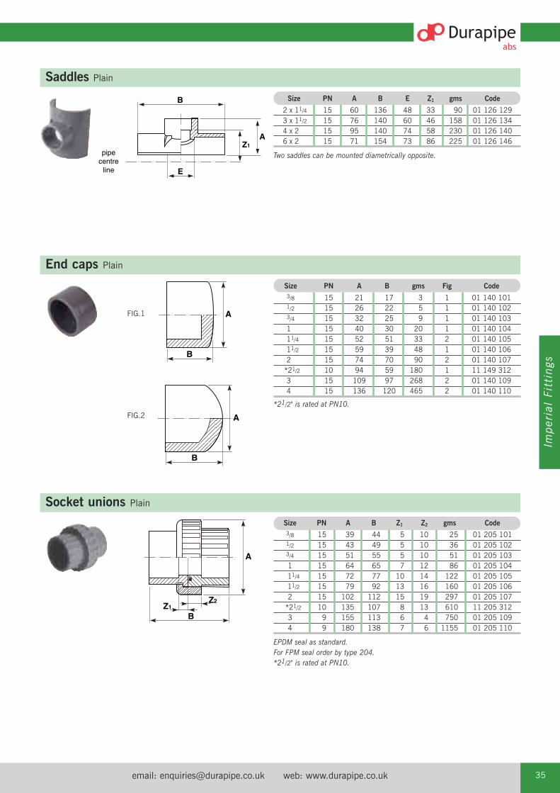
email: [email protected] web: www.durapipe.co.uk 35
Imperial Fittings
End caps Plain
Socket unions Plain
B
Z2Z1
A
B
A
Size PN A B gms Fig Code
3/8 15 21 17 3 1 01 140 101 1/2 15 26 22 5 1 01 140 102 3/4 15 32 25 9 1 01 140 103 1 15 40 30 20 1 01 140 104 11/4 15 52 51 33 2 01 140 105 11/2 15 59 39 48 1 01 140 106 2 15 74 70 90 2 01 140 107 *21/2 10 94 59 180 1 11 149 312 3 15 109 97 268 2 01 140 109 4 15 136 120 465 2 01 140 110
*21/2" is rated at PN10.
Size PN A B Z1 Z2 gms Code
3/8 15 39 44 5 10 25 01 205 101 1/2 15 43 49 5 10 36 01 205 102 3/4 15 51 55 5 10 51 01 205 103 1 15 64 65 7 12 86 01 205 104 11/4 15 72 77 10 14 122 01 205 105 11/2 15 79 92 13 16 160 01 205 106 2 15 102 112 15 19 297 01 205 107
*21/2 10 135 107 8 13 610 11 205 312 3 9 155 113 6 4 750 01 205 109 4 9 180 138 7 6 1155 01 205 110
EPDM seal as standard.For FPM seal order by type 204.*21/2" is rated at PN10.
B
E
AZ1
pipecentre
line
Saddles Plain
Size PN A B E Z1 gms Code
2 x 11/4 15 60 136 48 33 90 01 126 129 3 x 11/2 15 76 140 60 46 158 01 126 134 4 x 2 15 95 140 74 58 230 01 126 140 6 x 2 15 71 154 73 86 225 01 126 146
Two saddles can be mounted diametrically opposite.
FIG.1
B
AFIG.2

Tel: +44 (0)1543 279909 Fax: +44 (0)1543 27945036
BZ1
Reducing bushes Plain female BSP thread
Size PN B Z1 gms Code
1/2 x 3/8 12 17 6 4 01 111 121 3/8 x 1/2 12 20 5 7 01 111 122 1 x 3/4 12 23 6 12 01 111 124
A
Z1
C
Z1
Elbows 90° Plain female BSP thread
Size PN A C Z1 gms Code
1/2 12 26 34 17 26 01 116 102 3/4 12 32 36 20 34 01 116 103 1 12 40 41 23 63 01 116 104 11/2 12 62 57 30 136 01 116 106 2 12 75 66 35 203 01 116 107
B
Z1
A
Imperial/metric socket adaptors Plain Size PN A B Z1 gms Code
1/2 x 20 10 26 37 3 7 11 345 1023/4 x 25 10 31 41 3 12 11 345 1031 x 32 10 40 49 3 25 11 345 104
11/4 x 40 10 50 58 2 45 11 345 10511/2 x 50 10 59 67 3 62 11 345 1062 x 63 10 74 78 2 114 11 345 1073 x 90 10 107 105 3 355 11 345 1094 x 110 10 134 130 6 690 11 345 1106 x 160 10 195 183 8 1660 11 345 112
BC
Z1
A
Sockets Plain female BSP thread Size PN A B C Z1 gms Code
1/2 12 27 38 17 4 8 01 101 102 3/4 12 33 44 20 2 14 01 101 103 1 12 42 51 23 5 30 01 101 104 11/4 12 52 55 22 4 46 01 101 105 11/2 12 60 61 26 2 65 01 101 106 2 12 75 70 29 2 114 01 101 107 3 12 110 107 52 3 378 01 101 109

email: [email protected] web: www.durapipe.co.uk 37
Imperial Fittings
Female threaded adaptors Plain spigot end/female BSP thread
Size PN A B Z1 gms Code
1/2 12 27 38 16 8 01 153 102 3/4 12 36 44 18 14 01 153 103 1 12 43 50 21 24 01 153 104 11/4 12 55 60 22 49 01 153 105 11/2 12 63 66 25 68 01 153 106 2 12 78 78 29 129 01 153 107Z1
B
A
Hexagon nipples Plain spigot/male BSP thread Size PN A B D gms Code
3/8 12 24 36 11 7 01 107 101 1/2 12 30 42 15 12 01 107 102 3/4 12 36 48 16 30 01 107 103 1 12 46 56 20 40 01 107 104 11/4 12 46 60 21 50 01 107 105 11/2 12 55 63 22 58 01 107 106 2 12 72 74 26 91 01 107 107
B
D
A(A/F)
Male threaded fittings Plain/brass male thread Size D D1 l z SW Code
1⁄2 x 1⁄2 35 29 55 40 36 01 228 102 3⁄4 x 3⁄4 43 34 58 42 44 01 228 103 1 x 1 50 43 66 48 51 01 228 104 11⁄4 x 11⁄4 62 52 74 53 63 01 228 105
Size D D1 l z SW Code
1⁄2 x 1⁄2 35 29 40 11 36 01 229 102 3⁄4 x 3⁄4 43 34 42 11 44 01 229 103 1 x 1 50 43 48 12 51 01 229 104 11⁄4 x 11⁄4 62 55 54 13 63 01 229 105
Female threaded fittings Plain/brass female thread
ALL Durapipe Brass Components are manufactured using DZR Brass.
ALL Durapipe Brass Components are manufactured using DZR Brass.

Tel: +44 (0)1543 279909 Fax: +44 (0)1543 27945038
Barrel nipples Plain/BSP taper threaded
Size PN B D gms Code
3 12 128 30 252 01 316 109 4 12 153 36 525 01 316 110
B
D
B D
A(A/F)
C
E
Hose adaptors BSP taper threaded/hose tail Size PN A B C D E gms Code
1/2 12 26 60 41 13 14 8 01 157 102 3/4 12 28 66 41 16 20 15 01 157 103 1 12 40 73 46 19 27 28 01 157 104
Male threaded adaptors Plain/male BSP taper threaded
Size PN A B D Z1 gms Code
3/8 12 22 35 10 20 5 01 151 101 1/2 12 27 45 12 28 9 01 151 102 3/4 12 35 48 14 28 14 01 151 103
Z1
B
A
D
B
Z1
D
A(A/F)
Size PN A B D Z1 gms Code
1 12 46 58 19 35 36 01 151 104 11/4 12 56 66 22 38 70 01 151 105 11/2 12 72 75 22 43 115 01 151 106 2 12 80 85 26 46 150 01 151 107

email: [email protected] web: www.durapipe.co.uk 39
Imperial Fittings
Z1
A(A/F)
B
Z2
B
Z1
A(A/F)
Composite unions Plain/brass, female BSP parallel thread
Composite unions Plain/brass, male BSP taper thread
Size PN A B Z1 Z2 gms Code
1/2 15 40 42 3 7 165 01 212 102 3/4 15 48 49 3 9 290 01 212 103 1 15 55 59 11 12 310 01 212 104 11/4 15 65 68 9 10 450 01 212 105 11/2 15 79 75 12 14 800 01 212 106 2 15 88 90 14 14 950 01 212 107
Fitted with brass retaining nut.Brass material to BS2872, WRAS approved.
Size PN A B Z1 gms Code
1/2 15 40 54 3 175 01 217 102 3/4 15 48 74 3 320 01 217 103 1 15 55 86 8 420 01 217 104 11/4 15 65 94 10 620 01 217 105 11/2 15 78 108 13 1000 01 217 106 2 15 88 129 15 1200 01 217 107
Fitted with brass retaining nut. Brass material to BS2872, WRAS approved.
B
D
A(A/F) F C
Tank connectors Plain spigot/male BSP parallel thread Size A B C D F gms Code
1/2 28 70 38 28 15 26 01 235 102 3/4 33 77 38 38 21 30 01 235 103
B
A
Sockets Female BSP taper thread Size PN A B gms Code
1/2 12 26 38 12 01 102 102 3/4 12 33 43 22 01 102 103 1 12 41 51 34 01 102 104 11/4 12 51 54 60 01 102 105 11/2 12 62 63 87 01 102 106 2 12 75 72 132 01 102 107 3 12 110 107 437 01 102 109
ALL Durapipe Brass Components are manufactured using DZR Brass.
ALL Durapipe Brass Components are manufactured using DZR Brass.

Tel: +44 (0)1543 279909 Fax: +44 (0)1543 27945040
B
D
A(A/F)
Plugs Male BSP taper thread Size PN A B D gms Code
3/8 12 11 19 10 3 01 155 101 1/2 12 13 23 14 5 01 155 102 3/4 12 14 28 15 8 01 155 103 1 12 17 30 17 12 01 155 104 11/4 12 22 35 22 30 01 155 105 11/2 12 27 38 22 36 01 155 106 2 12 37 45 26 50 01 155 107
A
Z1
C
Elbows 90° Female BSP taper thread Size PN A C Z1 gms Code
1/2 12 26 29 17 27 01 117 102 3/4 12 32 33 19 39 01 117 103 1 12 41 41 23 65 01 117 104 11/2 12 63 57 30 141 01 117 106 2 12 75 67 35 212 01 117 107
B
A
D
End caps Female BSP taper thread
Size PN A B D gms Code
3/8 12 26 20 16 5 01 141 101 1/2 12 27 20 16 6 01 141 102 3/4 12 36 23 17 10 01 141 103 1 12 44 28 21 18 01 141 104 11/4 12 55 31 22 33 01 141 105 11/2 12 63 35 25 50 01 141 106 2 12 78 40 28 90 01 141 107 3 12 111 65 53 262 01 141 109
B
D
A(A/F)
Reducing bushes male/female BSP threadReducing bushes Male/female BSP thread
Size PN A B D gms Code
1/2 x 3/8 12 24 25 10 5 01 113 121 3/4 x 1/2 12 30 27 11 10 01 113 122 1 x 3/4 12 36 31 12 13 01 113 124
Male thread taper.Female thread parallel.

email: [email protected] web: www.durapipe.co.uk 41
Imperial Fittings
B
A(A/F)C
Back nuts Female BSP taper thread
Size PN A B C gms Code
3/8 12 25 11 29 5 01 159 101
1/2 12 28 13 38 8 01 159 102
3/4 12 33 13 38 15 01 159 103
1 12 45 16 54 18 01 159 104
11/4 12 50 18 58 19 01 159 105
11/2 12 60 19 69 31 01 159 106
2 12 79 21 91 65 01 159 107
Flanges stub Plain/serratedSize PN A B D Z1 gms Code
2 15 96 40 14 3 90 01 135 107
21/2 10 106 49 10 4 150 11 135 312
3 15 127 57 18 6 200 01 135 109
4 15 159 69 20 6 350 01 135 110
5 15 180 83 14 7 680 11 135 316
6 12 213 104 24 11 805 01 135 112
8 9 269 132 26 14 2075 01 135 113
B
D
A(A/F)
Hexagon nipples Male BSP taper thread Size PN A B D gms Code
3/8 12 24 38 14 6 01 106 101
1/2 12 30 46 18 12 01 106 102
3/4 12 36 50 19 30 01 106 103
1 12 46 59 13 40 01 106 104
11/4 12 46 67 27 55 01 106 105
11/2 12 55 73 29 75 01 106 106
2 12 72 81 33 125 01 106 107
B
D
Z1
A
All Durapipe flanges are designed for use with Durapipe backing rings. Guarantees are null and void if used with incorrect backing ring.

Tel: +44 (0)1543 279909 Fax: +44 (0)1543 27945042
Flanges full face Plain/drilled
BS10 Table D/ENo. of Hole
Size A B D Z1 P.C.D. Holes Diameter gms Code1/2 96 21 10 4 67 4 14 68 01 130 1023/4 105 24 10 4 73 4 14 78 01 130 1031 115 27 10 4 83 4 14 107 01 130 10411/4 140 33 10 5 87 4 14 122 01 130 10511/2 150 37 10 5 98 4 14 154 01 130 1062 166 45 10 6 115 4 18 223 01 130 1073 199 60 11 8 145 4 18 398 01 130 109*4 220 72 14 6 178 8 18 638 01 130 1106 284 98 22 8 235 8 22 1340 01 130 112
*4" BS10 Table D has 4 holes and should be ordered as 01 317 110.
BS4504 Table 16/3-10/3No. of Hole
Size A B D Z1 P.C.D. Holes Diameter gms Code1⁄2 96 21 10 4 65 4 14 68 01 319 1023⁄4 105 24 10 4 75 4 14 78 01 319 1031 115 27 10 4 85 4 14 107 01 319 10411⁄4 140 33 10 5 100 4 18 122 01 319 10511⁄2 150 37 10 5 110 4 18 154 01 319 1062 166 45 10 6 125 4 18 223 01 319 1073 199 60 11 8 160 8 18 398 01 319 1094 220 72 14 6 180 8 18 638 01 319 1106 284 98 22 8 240 8 22 1340 01 319 112
ANSI Class 150No. of Hole
Size A B D Z1 P.C.D. Holes Diameter gms Code1/2 96 21 10 4 60 4 14 68 01 322 1023/4 105 24 10 4 70 4 14 78 01 322 1031 115 27 10 4 80 4 14 107 01 322 10411/2 150 37 10 5 98 4 14 154 01 322 1062 166 45 10 6 121 4 18 223 01 322 1073 199 60 11 8 152 4 18 398 01 322 1094 220 72 14 6 190 8 18 638 01 322 1106 284 98 22 8 241 8 22 1340 01 322 112
Size PN A B D Z1 gms Code
1/2 15 96 21 10 4 75 01 129 102 3/4 15 105 24 10 4 85 01 129 103 1 15 115 27 10 4 111 01 129 104 11/4 15 140 32 10 4 130 01 129 105 11/2 15 150 36 10 5 160 01 129 106 2 15 165 45 11 6 233 01 129 107 3 15 199 60 11 8 414 01 129 109 4 15 220 73 14 6 657 01 129 110 6 12 284 99 22 8 1417 01 129 112
Note: Durapipe backing rings must be used in conjunction with full face flanges.
Undrilled
A
Z1
D B
All Durapipe flanges are designed for use with Durapipe backing rings. Guarantees are null and void if used with incorrect backing ring.

ANSI Class 150No. of Hole
Size A B P.C.D. Holes Diameter gms Code2 165 13 121 4 18 235 01 325 1073 197 19 152 4 18 520 01 325 1094 214 19 190 8 18 720 01 325 1106 286 26 241 8 22 1575 01 325 1128 337 26 298 8 22 2300 01 325 113
email: [email protected] web: www.durapipe.co.uk 43
Imperial Fittings
B
A
BS10 Table D/ENo. of Hole
Size A B P.C.D. Holes Diameter gms Code2 165 13 115 4 18 235 01 313 1073 197 19 145 4 18 520 01 313 109
*4 214 19 178 8 18 720 01 313 1106 286 26 235 8 22 1575 01 313 1128 337 26 292 8 22 2300 01 313 113
*4" BS10 Table D has 4 holes and should be ordered as 01 326 110.
Flanges blanking Plain/drilled
Size PN A B gms Code
1 15 116 13 140 01 131 10411/2 15 150 13 185 01 131 1062 15 166 13 235 01 131 1073 15 197 19 520 01 131 1094 15 214 19 720 01 131 1106 12 286 26 1575 01 131 1128 9 337 26 2300 01 131 113
Note: Durapipe backing rings must be used in conjunction with blank flanges.
Undrilled
BS4504 Table 16/3 (1/2" to 8") 10/3 (1/2" to 6")No. of Hole
Size A B P.C.D. Holes Diameter gms Code2 165 13 125 4 18 235 01 323 10721/2 186 19 145 4 18 568 11 323 3123 197 19 160 8 18 520 01 323 1094 214 19 180 8 18 720 01 323 1105 251 26 210 8 18 1338 11 323 3166 286 26 240 8 22 1575 01 323 1128 337 26 295 12 22 2300 01 323 113
All Durapipe flanges are designed for use with Durapipe backing rings. Guarantees are null and void if used with incorrect backing ring.
DURAPIPE UK MANUFACTURE FULLY MATCHED PIPEWORK SYSTEMS.
AS A RESULT WE DO NOT RECOMMEND THE USE OF NON-DURAPIPE PRODUCTSINCLUDING BACKING RINGS, GASKETS, SOLVENT CEMENT AND CLEANER.
INSIST ON DURAPIPE.

Tel: +44 (0)1543 279909 Fax: +44 (0)1543 27945044
B
AC P
L
Backing rings Galvanised mild steel drilled
BS10 Table D/ENo. of Hole Bolt Weight
Size A B C P Holes Dia. Size gms Code1⁄2 95 6 35 67 4 14 M12x50 270 03 416 1023/4 103 7 45 73 4 14 M12x50 300 03 416 1031 114 6 49 83 4 14 M12x50 380 03 416 10411/4 120 7 60 87 4 14 M12x50 380 03 416 10511⁄2 135 7 68 98 4 14 M12x50 480 03 416 1062 151 8 78 115 4 18 M16x65 880 03 416 1073 187 9 110 145 4 18 M16x70 1040 03 416 109*4 216 9 140 178 8 18 M16x80 1330 03 416 1106 282 11 195 235 8 22 M20x90 2340 03 416 1128 337 10 255 292 8 22 M20x100 2870 03 416 113
*4" BS10 Table D has 4 holes and should be ordered as 03 415 110.
BS4504 Table 16/3 (1/2" to 12") 10/3 (1/2" to 6")
No. of Hole Bolt WeightSize A B C P Holes Dia. Size gms Code1/2 95 6 35 65 4 14 M12x50 310 03 421 1023/4 106 6 45 75 4 14 M12x50 330 03 421 1031 114 6 49 85 4 14 M12x50 390 03 421 10411/4 141 6 60 100 4 18 M16x50 580 03 421 10511/2 150 6 68 110 4 18 M16x50 880 03 421 1062 165 8 78 125 4 18 M16x65 1020 03 421 10721/2 186 9 92 145 4 18 M16x65 1280 13 421 3123 200 8 110 160 8 18 M16x70 1310 03 421 1094 221 8 140 180 8 18 M16x80 1370 03 421 1105 251 11 167 210 8 18 M16x90 2060 13 421 3166 286 11 195 240 8 22 M20x90 2460 03 421 1128 339 11 255 295 12 22 M20x100 2780 03 421 113
BS4504 Table 10/3 (8")
No. of Hole Bolt WeightSize A B C P Holes Dia. Size gms Code8 339 11 255 295 8 22 M20x100 2870 03 404 113
ANSI Class 150No. of Hole Bolt Weight
Size A B C P Holes Dia. Size gms Code1/2 89 6 35 60 4 14 M12x50 240 03 425 1023/4 98 6 45 70 4 14 M12x50 270 03 425 1031 108 6 49 80 4 14 M12x50 330 03 425 10411/2 128 6 68 98 4 14 M12x50 420 03 425 1062 153 8 78 121 4 18 M16x65 790 03 425 1073 191 8 110 152 4 18 M16x65 1200 03 425 1094 230 9 140 190 8 18 M16x70 1580 03 425 1106 280 11 195 241 8 22 M20x90 2230 03 425 1128 340 12 255 298 8 22 M20x100 3060 03 425 113
Note: The 8" backing ring drilled 10/3 is intended for use in conjunction with the 8"FK Butterfly valve, as the PN10 drilling has 8 holes as apposed to the 12 holes on thePN16 drilling.
*Bolt lengths shown are for flange/flange assemblies only.

email: [email protected] web: www.durapipe.co.uk 45
Imperial Fittings
Gaskets full face Drilled EPDM
B
A
BS10 Table D/ENo. of Hole
Size A B P.C.D. Holes Diameter gms Code1/2 95 3.0 67 4 14 31 03 410 1023/4 112 3.0 73 4 14 37 03 410 1031 115 3.0 83 4 14 37 03 410 10411/4 121 3.0 87 4 14 41 03 410 10511/2 133 3.0 98 4 14 55 03 410 1062 153 3.0 115 4 18 56 03 410 1073 184 3.0 145 4 18 98 03 410 109*4 216 3.2 178 8 18 112 03 410 1106 250 3.1 235 8 22 160 03 410 112
*4" BS10 Table D has 4 holes and should be ordered as 03 409 110.
BS4504 Table 16/3-10/3No. of Hole
Size A B P.C.D. Holes Diameter gms Code1/2 95 3.0 65 4 14 31 03 408 1023/4 112 3.0 75 4 14 37 03 408 1031 115 3.0 85 4 14 37 03 408 10411/4 121 3.0 100 4 18 41 03 408 10511/2 133 3.0 110 4 18 55 03 408 1062 153 3.0 125 4 18 56 03 408 1073 184 3.0 160 8 18 98 03 408 1094 216 3.2 180 8 18 112 03 408 1106 280 3.1 240 8 22 160 03 408 112
ANSI Class 150No. of Hole
Size A B P.C.D. Holes Diameter gms Code1/2 95 3.0 60 4 14 31 03 426 1023/4 112 3.0 70 4 14 37 03 426 1031 115 3.0 80 4 14 37 03 426 10411/2 133 3.0 98 4 14 55 03 426 1062 153 3.0 121 4 18 56 03 426 1073 184 3.0 152 4 18 98 03 426 1094 216 3.2 190 8 18 112 03 426 1106 280 3.1 241 8 22 160 03 426 112
B
A
Gaskets flat Stub flange EPDM
Size A B gms Code
2 97 3.0 21 03 431 107 21/2 106 3.0 22 13 411 312 3 128 3.0 23 03 431 109 4 160 3.9 36 03 431 110 5 180 4.0 60 13 411 316 6 214 3.9 74 03 431 112 8 269 4.0 92 03 431 113

Tel: +44 (0)1543 279909 Fax: +44 (0)1543 27945046
C
P
M
L
EB
BS4504 Table 16/3 (1/2" to 8") 10/3 (1/2" to 6")Size B C E L M N P Weight Code
gms1/2 95 86 50 14 16 2 65 370 03 458 1023/4 106 89 75 14 16 2 75 450 03 458 103
1 143 99 75 14 16 2 85 560 03 458 104
11/4 152 105 75 14 16 2 100 950 03 458 105
11/2 151 105 74 14 16 2 110 1150 03 458 106
2 166 127 101 14 17 2 125 1380 03 458 107
21/2 185 144 125 14 22 2 145 2500 31 459 312
3 201 143 127 14 22 2 160 1650 03 458 109
4 222 161 151 14 24 3 180 2550 03 458 110
6 286 217 228 14 33 3 240 4100 03 458 112
8 340 242 280 14 31 3 295 6250 03 458 113
N = No. of holes in base.
Valve support plates Galvanised mild steel
B
O-Ring for socket unions For use with socket unions
EPDM FPM Size B gms Code Code
3/8 3.5 0.5 03 209 101 03 211 101 1/2 3.5 1 03 209 102 03 211 102 3/4 3.5 2 03 209 103 03 211 103 1 3.5 3 03 209 104 03 211 104 11/4 5.2 5 03 209 105 03 211 105 11/2 5.2 6 03 209 106 03 211 106 2 5.3 7 03 209 107 03 211 107

email: [email protected] web: www.durapipe.co.uk 47
Imperial Fittings
VKD Double union ball valves Manual – EPDM seals
Options:FPM seals (plain ends) order H0 DKB***FPM seals (threaded ends) order H0 DKB***
Manual valves can be supplied with locking kits - further information is available from ourValve Department.
d DN PN L Z H E B C gms Code
3/8 10 16 14.5 74 103 55 49 66 195 H0 DKA 1011/2 15 16 16.5 70 103 55 49 66 195 H0 DKA 1023/4 20 16 19 77 115 66 59 75 315 H0 DKA 103
1 25 16 22.5 83 128 75 66 85 435 H0 DKA 104
11/4 32 16 26 94 146 87 75 97 655 H0 DKA 105
11/2 40 16 30 104 164 100 87 110 880 H0 DKA 106
2 50 16 36 127 199 122 101 134 1560 H0 DKA 107
Valves
d DN PN Z L H H1 E B B1 C C1 gms Code
21/2 65 16 147 44 235 133 164 164 87 225 175 4380 H0 DKA 108
3 80 16 168 51 270 149 203 177 105 327 272 7200 H0 DKA 109
4 100 16 186 61 308 167 238 195 129 385 330 11141 H0 DKA 110
Options:FPM seals (plain ends) order H0 DKB***
TKD 3-way ball valves Manual – EPDM seals
Options:FPM seals (plain ends) order H0 TTB***FPM seals (threaded ends) order H0 TTB***
Manual valves can be supplied with locking kits - further information is available from ourValve Department.
d DN PN H Z C C1 B B1 gms Code
1/2 15 16 125 95 67 40 54 29 310 H0 TTA 1023/4 20 16 146 114 85 49 65 34.5 550 H0 TTA 103
1 25 16 166 129 85 49 65.9 39 790 H0 TTA 104
11/4 32 16 195.5 151 108 64 82.5 46 1275 H0 TTA 105
11/2 40 16 211 166 108 64 89 52 1660 H0 TTA 106
2 50 16 253.5 199 134 76 108 62 2800 H0 TTA 107
d DN PN H Z C C1 B B1 gms Code
1/2 15 16 125 95 67 40 54 29 310 H0 LTA 1023/4 20 16 146 114 85 49 65 34.5 550 H0 LTA 103
1 25 16 166 129 85 49 65.9 39 790 H0 LTA 104
11/4 32 16 195.5 151 108 64 82.5 46 1275 H0 LTA 105
2 50 16 253.5 199 134 76 108 62 2800 H0 LTA 107
Options:FPM seals (plain ends) order H0 LTB***
VKD & TKD ball valves can be supplied electrically or pneumatically actuated.
T port design
L port design

Tel: +44 (0)1543 279909 Fax: +44 (0)1543 27945048
Size L Z C E gms Code1/2 17 48 82 50 96 H0 UCA 1023/4 19 55 93 59 99 H0 UCA 1031 22 62 106 68 145 H0 UCA 10411/4 26 75 127 80 234 H0 UCA 10511/2 31 84 146 96 357 H0 UCA 1062 38 99 175 116 937 H0 UCA 107
UC Ball check valves Plain ends – EPDM seals (other options available)
Options:EPDM seals (threaded ends) order H0 UCA B**FPM seals (plain ends) order H0 UCB***FPM seals (threaded ends) order H0 UCB B**
UA Air release valves Plain ends – EPDM seals (other options available)
Size L Z C E gms Code1/2 17 48 82 50 96 H0 UAA 1023/4 19 55 93 59 99 H0 UAA 1031 22 62 106 68 145 H0 UAA 10411/4 26 75 127 80 234 H0 UAA 10511/2 31 84 146 96 357 H0 UAA 1062 38 99 175 116 937 H0 UAA 107
Options:EPDM seals (threaded ends) order H0 UAA B**FPM seals (plain ends) order H0 UAB***FPM seals (threaded ends) order H0 UAB B**
Note: this valve must be installed at a minimum distance of 10 x nominal diameter (eg. 20" for size 2") from pump flange.
EV Double union ball valves Manual – EPDM seals
d DN PN L Z C E H B gms CodePlain Threaded
1/2 15 10 17 47 81 50 50 57 95 H0 EVA 102 H0 EVA B023/4 20 10 19 51 95 59 55 66 156 H0 EVA 103 H0 EVA B03
1 25 10 22 61 105 68 66.5 75 228 H0 EVA 104 H0 EVA B04
11/4 32 10 31 84 146 96 93 103 540 H0 EVA 105 H0 EVA B05
11/2 40 10 31 84 146 96 93 103 540 H0 EVA 106 H0 EVA B06
2 50 10 38 96 172 116 107 121 844 H0 EVA 107 H0 EVA B07
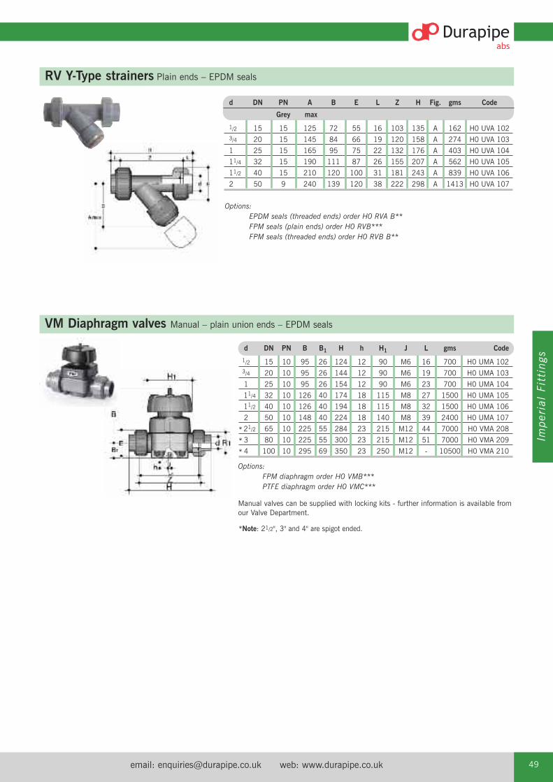
email: [email protected] web: www.durapipe.co.uk 49
Imperial Fittings
RV Y-Type strainers Plain ends – EPDM seals
Options:EPDM seals (threaded ends) order H0 RVA B**FPM seals (plain ends) order H0 RVB***FPM seals (threaded ends) order H0 RVB B**
VM Diaphragm valves Manual – plain union ends – EPDM seals
Options:FPM diaphragm order H0 VMB***PTFE diaphragm order H0 VMC***
Manual valves can be supplied with locking kits - further information is available fromour Valve Department.
d DN PN B B1 H h H1 J L gms Code
1/2 15 10 95 26 124 12 90 M6 16 700 H0 UMA 1023/4 20 10 95 26 144 12 90 M6 19 700 H0 UMA 103
1 25 10 95 26 154 12 90 M6 23 700 H0 UMA 104
11/4 32 10 126 40 174 18 115 M8 27 1500 H0 UMA 105
11/2 40 10 126 40 194 18 115 M8 32 1500 H0 UMA 106
2 50 10 148 40 224 18 140 M8 39 2400 H0 UMA 107
21/2 65 10 225 55 284 23 215 M12 44 7000 H0 VMA 208
3 80 10 225 55 300 23 215 M12 51 7000 H0 VMA 209
4 100 10 295 69 350 23 250 M12 - 10500 H0 VMA 210
d DN PN A B E L Z H Fig. gms Code
Grey max
1/2 15 15 125 72 55 16 103 135 A 162 H0 UVA 1023/4 20 15 145 84 66 19 120 158 A 274 H0 UVA 103
1 25 15 165 95 75 22 132 176 A 403 H0 UVA 104
11/4 32 15 190 111 87 26 155 207 A 562 H0 UVA 105
11/2 40 15 210 120 100 31 181 243 A 839 H0 UVA 106
2 50 9 240 139 120 38 222 298 A 1413 H0 UVA 107
*
*
*
*Note: 21/2", 3" and 4" are spigot ended.

Tel: +44 (0)1543 279909 Fax: +44 (0)1543 27945050
PR Pressure relief valves EPDM sealsC
ZEG
B
A
D
F
Size PN Z A B C D E F G gms Code1⁄2 10 92 143 20.5 35 124 M6 25 12 700 H0 PRA 2023⁄4 10 106 143 20.5 35 144 M6 25 12 700 H0 PRA 203
1 10 108 143 25.0 35 154 M6 25 12 700 H0 PRA 204
11⁄4 10 120 204 36.0 50 174 M8 44.5 16 1500 H0 PRA 205
11⁄2 10 130 204 39.5 50 194 M8 44.5 16 1500 H0 PRA 206
2 10 146 219 49.0 50 224 M8 44.5 16 2400 H0 PRA 207
Options:FPM seals order H0 PRB***
Size DN PN B2 B3 C C1 Z gms U Code
11⁄2 40 16 60 137 175 100 33 900 4 H0 FKA 1062 50 16 70 143 175 100 43 1080 4 H0 FKA 10721⁄2 65 10 80 164 272 110 46 1470 4 H0 FKA 1083 80 10 93 178 272 110 49 1870 8 H0 FKA 1094 100 10 107 192 272 110 56 2220 8 H0 FKA 1105 125 10 120 212 330 110 64 3100 8 H0 FKA 1116 150 10 134 225 330 110 70 3850 8 H0 FKA 1128 200 10 161 272 420 122 71 6750 8 H0 FKA 113
FK Butterfly valves Glass reinforced polypropylene with ABS disc and EPDM seals
Size DN PN B2 B5 B6 G G1 G2 G3 Z gms U Code
21⁄2 65 10 80 174 146 48 135 39 125 46 2400 4 HV FKA 1083 80 10 93 188 160 48 135 39 125 49 2800 8 HV FKA 1094 100 10 107 202 174 48 135 39 125 56 3150 8 HV FKA 1105 125 10 120 222 194 48 144 39 200 64 4450 8 HV FKA 1116 150 10 134 235 207 48 144 39 200 70 5200 8 HV FKA 1128 200 10 161 287 256 65 204 60 200 71 9300 8 HV FKA 11310 250 10 210 317 281 88 236 76 250 114 18600 12 HV FKA 11412 300 8 245 374 338 88 236 76 250 114 25600 12 HV FKA 115
lever operated
with gear box
Options:FPM seals order HV FKB***
Options:FPM seals order H0 FKB***
U = No. of holes
U = No. of holes
Note: Lugged versions available to special order. Please refer to our Valve Departmentfor further details.
Valves can be supplied as electrically or pneumatically actuated. For further details contact our Valve department on 01543 272424.

email: [email protected] web: www.durapipe.co.uk 51
Imperial Fittings
BG
C
A
D
G E
C
F
Cobra pipe clips PolypropyleneSize A B C D G Bolt/Screw size gms Code
3/8 – 35 25 19 16 M.4/3BA/No 8 7 13 434 305 1/2 – 35 30 14 16 M.5/1BA/No 10 8 13 434 306 3/4 – 35 35 16 17 M.5/1BA/No 10 11 13 434 307 1 – 40 40 17 17 M.5/1BA/No 10 14 13 434 30811/4 75 45 45 20 20 M.5/1BA/No 10 21 13 434 30911/2 85 50 50 22 21 M.6/0BA/No 10 30 13 434 310 2 102 60 60 19 21 M.6/0BA/No 10 42 13 434 31121/2 122 70 70 27 31 M.8 94 13 434 312 3 148 80 90 39 31 M.8 121 13 434 313 4 171 90 96 36 35 M.8 185 13 434 314 5 211 156 132 40 40 M.8 252 13 434 316 6 243 170 150 40 40 M.8 330 13 434 317
Clips of size 11/4" and above are fitted with retaining strap. Bolts/screws not supplied.
Saddle clips PolypropyleneSize C E F G Bolt/Screw size gms Code3/8 13 37 – 14 M.4/3BA/No 8 3 03 455 1011/2 18 41 – 14 M.4/3BA/No 8 4 03 455 1023/4 21 45 – 16 M.5/2BA/No 10 6 03 455 1031 23 56 – 16 M.5/2BA/No 10 7 03 455 10411/4 29 65 – 16 M.5/2BA/No 10 11 03 455 10511/2 34 67 – 16 M.5/2BA/No 10 12 03 455 1062 38 87 – 22 M.6/0BA/No 12 25 03 455 1073 50 122 8 34 M.10/3⁄8UNC 45 03 455 1094 65 156 13 38 M.10/3⁄8UNC 70 03 455 110
Backing plate shown dotted supplied with 3" and 4" only.Bolts/screws not supplied. Bolt holes in 3" and 4" clips are not countersunk.
One-step solvent cement
Only Durapipe ABS solvent cement and Durapipe Eco-cleanershould be used for jointing of Durapipe ABS pipework systems.
Eco-cleaner Litres gms Code
0.5 500 03 457 395
Only Durapipe ABS solvent cement and Durapipe Eco-cleanershould be used for jointing of Durapipe ABS pipework systems.
Litres gms Code
0.5 550 03 461 395
1.0 1100 03 461 396
Accessories
Chamfering and de-burring tools
Pipe cutters
Description Product code3/8" to 1" pipe inner and outer milling cutter tool FT 55 72 903/8" to 2" pipe inner and outer milling cutter tool FT 55 65 123/4" to 6" chamfering tool FT 55 05 10
Description Product code3/8" to 2" pipe cutter FT 80 00 0111/2" to 4" pipe cutter FT 80 00 033/8" to 2" spare cutter wheel FT 80 00 0211/2" to 4" spare cutter wheel FT 80 00 04

Tel: +44 (0)1543 279909 Fax: +44 (0)1543 27945052
Elbows 90° (plain)page 56
Elbows 45° (plain)page 55
Reducing sockets (plain)page 55
Pipe (plain)page 54
Bends 90°(short radius)page 57
Bends 90°(long radius)page 58
Sockets (plain)page 54
O-Ring sockets(galvanised mild steel)page 64
Reducing bushes (plain)page 55
Tees 90° (equal)page 56
Tees 90° (swept plain)page 57
Flat gaskets for use withstub flangespage 64
Backing rings(galvanised mild steel)page 63
Valve support plates (galvanised mild steel)page 64
Flanges blankingpage 62
Flanges stub(plain serrated)page 62
Wall brackets(ABS/brass body)page 61
Male composite unions(plain/brass, male BSPparallel thread) page 61
Female composite unions(plain/brass, female BSPparallel thread) page 60
Hose adaptors(spigot end/hose tail)page 60
Male threaded adaptors(BSP taper male thread) page 59
Female threaded adaptors(plain spigot/plainsocket/female BSP thread)page 59
Imperial/metric socketadaptors (plain)page 58
Socket unions (plain)page 58
Tees 45° (plain)page 56
End caps (plain)page 58
Tees 90° (reducing plain)page 57
Index to ABS Metric FittingsNote: Two-dimensional Auto-CAD drawings are available on www.durapipe.co.uk
Male threaded fittings(plain/brass male thread)page 59
Female threaded fittings(plain/brass female thread) page 60
Half faced unionspage 60
Flexible hoses(plain spigot/BSP thread)page 61

email: [email protected] web: www.durapipe.co.uk 53
Metric Fittings
TKD 3-way ball valves(manual – EPDM seals)page 65
UC Ball check valves(EPDM seals)page 66
FK Butterfly valves(glass reinforced polypropylenewith ABS disc) page 68
Pipe trayspage 70
Chamfering and de-burring toolspage 70
Pipe cutterspage 69
VM Diaphragm valves(manual – plain unionends – EPDM seals)page 67
UA Air release valves(EPDM seals)page 66
RV Y-Type strainers(plain ends – EPDMseals) page 67
PR Pressure relief valves(EPDM seals)page 67
VKD Double union ball valves (manual –EPDM seals)page 65
One-step solvent cementpage 69
Eco-cleaner page 69
Cobra pipe clipspage 68
Rubber lined pipe clipspage 69
EV Double union ballvalves (manual – EPDMseals) page 66
Valves
Accessories

Tel: +44 (0)1543 279909 Fax: +44 (0)1543 27945054
ABS Pipe metric system Plain PN10
Size Thickness Weight Length Code t Da mm kg/m m 16 1.5 0.07 3 11 565 305 20 1.6 0.10 3 11 565 306 25 1.9 0.14 3 11 565 307 35 2.1 0.21 3 11 565 308
16 1.5 0.07 5 11 555 305 20 1.6 0.10 5 11 555 306 25 1.9 0.14 5 11 555 307 32 2.1 0.21 5 11 555 308 40 2.7 0.33 5 11 555 309 50 3.4 0.52 5 11 555 310 63 4.2 0.81 5 11 555 311 75 5.0 1.14 5 11 555 312 90 6.0 1.65 5 11 555 313 110 7.3 2.45 5 11 555 314 125 8.2 3.13 5 11 555 315 140 9.3 3.97 5 11 555 316 160 10.5 5.13 5 11 555 317 200 13.2 8.06 5 11 555 318 225 14.8 10.17 5 11 555 319 250 16.1 12.31 5 11 555 320 *315 20.8 20.00 5 11 555 323
16 1.5 0.07 6 11 551 305 20 1.6 0.10 6 11 551 306 25 1.9 0.14 6 11 551 307 32 2.1 0.21 6 11 551 308 40 2.7 0.33 6 11 551 309 50 3.4 0.52 6 11 551 310 63 4.2 0.81 6 11 551 311 75 5.0 1.14 6 11 551 312 90 6.0 1.65 6 11 551 313 110 7.3 2.45 6 11 551 314 125 8.2 3.13 6 11 551 315 140 9.3 3.97 6 11 551 316 160 10.5 5.13 6 11 551 317 200 13.2 8.06 6 11 551 318 225 14.8 10.17 6 11 551 319 250 16.1 12.31 6 11 551 320 *315 20.8 20.00 6 11 551 323*315 is PN8 rated.
Da(min)
t(mean)
B
Z1
A
Sockets Plain Size PN A B Z1 gms Code 16 10 21 31 3 5 11 100 305 20 10 25 37 3 7 11 100 306 25 10 31 42 2 12 11 100 307 32 10 41 49 3 25 11 100 308 40 10 50 58 4 45 11 100 309 50 10 62 68 4 77 11 100 310 63 10 78 81 4 154 11 100 311 75 10 88 93 3 230 11 100 312 90 10 107 108 4 380 11 100 313 110 10 126 131 7 690 11 100 314 125 10 146 149 7 1040 11 100 315 140 10 171 163 7 1390 11 100 316 160 10 182 184 8 1660 11 100 317 200 10 223 220 8 2390 11 100 318 225 10 260 250 11 3470 11 100 319 250 10 286 272 10 5760 11 100 320 315 8 355 339 11 9780 11 100 323
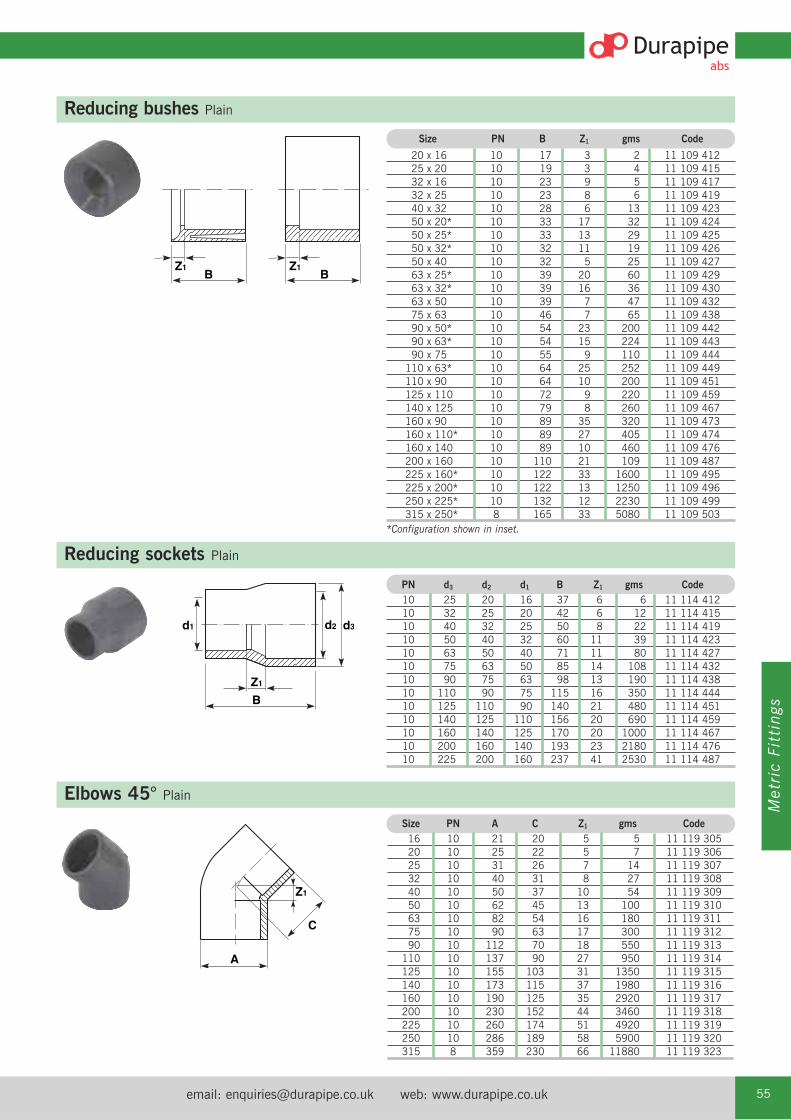
email: [email protected] web: www.durapipe.co.uk 55
Metric Fittings
B
d3
Z1
d1 d2
Reducing sockets Plain
PN d3 d2 d1 B Z1 gms Code10 25 20 16 37 6 6 11 114 41210 32 25 20 42 6 12 11 114 41510 40 32 25 50 8 22 11 114 41910 50 40 32 60 11 39 11 114 42310 63 50 40 71 11 80 11 114 42710 75 63 50 85 14 108 11 114 43210 90 75 63 98 13 190 11 114 43810 110 90 75 115 16 350 11 114 44410 125 110 90 140 21 480 11 114 45110 140 125 110 156 20 690 11 114 45910 160 140 125 170 20 1000 11 114 46710 200 160 140 193 23 2180 11 114 47610 225 200 160 237 41 2530 11 114 487
Z1
A
C
Elbows 45° Plain Size PN A C Z1 gms Code 16 10 21 20 5 5 11 119 305 20 10 25 22 5 7 11 119 306 25 10 31 26 7 14 11 119 307 32 10 40 31 8 27 11 119 308 40 10 50 37 10 54 11 119 309 50 10 62 45 13 100 11 119 310 63 10 82 54 16 180 11 119 311 75 10 90 63 17 300 11 119 312 90 10 112 70 18 550 11 119 313 110 10 137 90 27 950 11 119 314 125 10 155 103 31 1350 11 119 315 140 10 173 115 37 1980 11 119 316 160 10 190 125 35 2920 11 119 317 200 10 230 152 44 3460 11 119 318 225 10 260 174 51 4920 11 119 319 250 10 286 189 58 5900 11 119 320 315 8 359 230 66 11880 11 119 323
BZ1
BZ1
Reducing bushes Plain Size PN B Z1 gms Code 20 x 16 10 17 3 2 11 109 412 25 x 20 10 19 3 4 11 109 415 32 x 16 10 23 9 5 11 109 417 32 x 25 10 23 8 6 11 109 419 40 x 32 10 28 6 13 11 109 423 50 x 20* 10 33 17 32 11 109 424 50 x 25* 10 33 13 29 11 109 425 50 x 32* 10 32 11 19 11 109 426 50 x 40 10 32 5 25 11 109 427 63 x 25* 10 39 20 60 11 109 429 63 x 32* 10 39 16 36 11 109 430 63 x 50 10 39 7 47 11 109 432 75 x 63 10 46 7 65 11 109 438 90 x 50* 10 54 23 200 11 109 442 90 x 63* 10 54 15 224 11 109 443 90 x 75 10 55 9 110 11 109 444 110 x 63* 10 64 25 252 11 109 449 110 x 90 10 64 10 200 11 109 451 125 x 110 10 72 9 220 11 109 459 140 x 125 10 79 8 260 11 109 467 160 x 90 10 89 35 320 11 109 473 160 x 110* 10 89 27 405 11 109 474 160 x 140 10 89 10 460 11 109 476 200 x 160 10 110 21 109 11 109 487 225 x 160* 10 122 33 1600 11 109 495 225 x 200* 10 122 13 1250 11 109 496 250 x 225* 10 132 12 2230 11 109 499 315 x 250* 8 165 33 5080 11 109 503*Configuration shown in inset.

Tel: +44 (0)1543 279909 Fax: +44 (0)1543 27945056
A
Z1
C
Elbows 90° Plain Size PN A C Z1 gms Code 16 10 20 24 10 6 11 115 305 20 10 25 28 11 10 11 115 306 25 10 31 34 15 17 11 115 307 32 10 40 41 18 35 11 115 308 40 10 50 47 20 68 11 115 309 50 10 62 59 26 129 11 115 310 63 10 78 71 31 230 11 115 311 75 10 90 83 38 385 11 115 312 90 10 112 100 49 690 11 115 313 110 10 136 125 63 1220 11 115 314 125 10 155 140 63 1720 11 115 315 140 10 173 153 76 2390 11 115 316 160 10 190 172 79 3600 11 115 317 200 10 235 207 110 4300 11 115 318 225 10 261 240 119 6550 11 115 319 250 10 286 319 188 9560 11 115 320 315 8 359 400 236 17910 11 115 323
C
Z1
BAZ1
Tees 90° Equal
Size PN A B C Z1 gms Code16 10 21 47 25 10 7 11 122 30520 10 25 57 30 12 12 11 122 30625 10 31 67 34 15 24 11 122 30732 10 40 81 43 18 48 11 122 30840 10 50 99 50 23 87 11 122 30950 10 62 119 62 28 160 11 122 31063 10 78 146 70 34 300 11 122 31175 10 90 172 87 36 510 11 122 31290 10 112 205 104 46 900 11 122 313110 10 132 248 128 60 1650 11 122 314125 10 154 276 143 67 2300 11 122 315140 10 172 307 153 72 3200 11 122 316160 10 191 343 172 86 4800 11 122 317200 10 237 413 206 101 5800 11 122 318225 10 262 482 240 120 7700 11 122 319250 10 286 518 259 128 10160 11 122 320315 8 360 652 326 162 19390 11 122 323
B
A
Z3
Z1
C
Z2
Tees 45° PlainSize PN A B C Z1 Z2 Z3 gms Code
20 10 28 68 43 6 26 34 30 11 418 30625 10 33 81 52 7 29 55 45 11 418 30732 10 41 98 65 9 42 52 80 11 418 30840 10 50 117 77 11 51 65 135 11 418 30950 10 60 140 95 12 63 78 195 11 418 31063 10 74 169 114 13 76 93 410 11 418 311
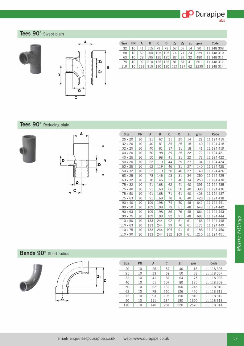
email: [email protected] web: www.durapipe.co.uk 57
Metric Fittings
C
Z1
D
A
Z3
Z2B
Tees 90° Swept plain
Size PN A B C D Z1 Z2 Z3 gms Code
32 10 41 115 79 79 57 57 14 90 11 148 308 50 10 62 160 105 105 74 74 24 259 11 148 310 63 10 78 195 125 125 87 87 32 480 11 148 311 75 10 92 210 125 125 81 81 41 601 11 148 312 110 10 139 315 190 190 127 127 62 2235 11 148 314
A
D
Z1
C
Z1B
Tees 90° Reducing plain
Size PN A B C D Z1 gms Code
25 x 20 10 31 67 31 25 14 22 11 124 41532 x 20 10 40 81 35 25 18 40 11 124 41832 x 25 10 40 81 37 31 18 41 11 124 41940 x 20 10 50 98 39 25 22 72 11 124 42140 x 25 10 50 98 41 31 22 72 11 124 42250 x 20 10 62 119 44 29 27 104 11 124 42450 x 25 10 62 119 46 31 27 140 11 124 42550 x 32 10 62 119 50 40 27 140 11 124 42663 x 25 10 78 146 53 31 34 250 11 124 42963 x 32 10 78 146 57 40 34 250 11 124 43075 x 32 10 91 168 62 41 40 391 11 124 43575 x 40 10 91 168 66 50 40 398 11 124 43675 x 50 10 91 168 71 61 40 406 11 124 43775 x 63 10 91 168 78 76 40 428 11 124 43890 x 40 10 109 198 74 50 48 642 11 124 44190 x 50 10 109 198 79 61 48 649 11 124 44290 x 63 10 109 198 86 76 48 664 11 124 44390 x 75 10 109 198 92 91 48 693 11 124 444110 x 50 10 133 244 92 61 61 1165 11 124 448110 x 63 10 133 244 99 76 61 1173 11 124 449110 x 75 10 133 244 105 91 61 1188 11 124 450110 x 90 10 133 244 112 109 61 1210 11 124 451
Z1
C
A
Bends 90° Short radius
Size PN A C Z1 gms Code
20 10 26 57 40 18 11 118 306 25 10 33 69 50 38 11 118 307 32 10 41 87 64 75 11 118 308 40 10 51 107 80 135 11 118 309 50 10 62 132 100 245 11 118 310 63 10 78 165 126 470 11 118 311 75 10 93 195 150 810 11 118 312 90 10 111 234 180 1350 11 118 313 110 10 140 284 220 2570 11 118 314

Tel: +44 (0)1543 279909 Fax: +44 (0)1543 27945058
CR
E
Bends 90° Long radius
Size C E R gms Code
125 750 250 500 4790 11 309 315 140 840 280 560 6700 11 309 316 160 960 320 640 10040 11 309 317 200 1200 400 800 19480 11 309 318 225 1350 450 900 27850 11 309 319
B
A
B
Z2Z1
A
End caps Plain
Socket unions Plain
Size PN A B Weight Codegms
16 10 21 16 3 11 149 30520 10 25 21 5 11 149 30625 10 31 24 8 11 149 30732 10 41 30 19 11 149 30840 10 50 35 30 11 149 30950 10 62 41 53 11 149 31063 10 78 50 106 11 149 31175 10 94 59 180 11 149 31290 10 112 70 300 11 149 313110 10 136 84 570 11 149 314
Size PN A B Z1 Z2 Weight Code gms
16 10 34 42 3 10 19 11 205 305 20 10 40 47 3 10 29 11 205 306 25 10 50 53 3 10 46 11 205 307 32 10 57 64 8 11 70 11 205 308 40 10 73 78 10 13 140 11 205 309 50 10 80 92 13 15 154 11 205 310 63 10 102 111 14 20 270 11 205 311 75 10 135 107 8 13 720 11 205 312 90 10 157 115 7 4 750 11 205 313 110 10 183 138 8 7 1115 11 205 314
EPDM seal as standard.For FPM seal order by type 204.
B
Z1
A
Imperial/metric socket adaptors PlainSize PN A B Z1 Weight Code
gms
*1/2 - 20 10 26 37 3 11 11 345 102 *3/4 - 25 10 31 41 3 23 11 345 103 *1 - 32 10 40 49 3 40 11 345 104
*11/4 - 40 10 50 58 2 80 11 345 105*11/2 - 50 10 59 67 3 160 11 345 106
*2 - 63 10 74 78 2 230 11 345 107 *3 - 90 10 107 105 3 340 11 345 109 *4 - 110 10 134 130 6 675 11 345 110 *6 - 160 10 195 183 8 1890 11 345 112
*Sizes shown in imperial n.b. designation.

email: [email protected] web: www.durapipe.co.uk 59
Metric Fittings
Z1
Z2
B
d1 d2 AT
Female threaded adaptors Plain spigot/plain socket/female BSP threadSize Weightd2 d1 PN T* A B Z1 Z2 gms Code
16- 12- 10 3⁄8 24 28 11 16 7 11 153 33120- 16- 10 1⁄2 30 35 15 21 14 11 153 33325- 20- 10 3⁄4 38 39 16 22 21 11 153 33532- 25- 10 1 45 45 18 26 42 11 153 33740- 32- 10 11⁄4 56 54 21 31 69 11 153 33950- 40- 10 11⁄2 64 60 21 33 108 11 153 34163- 50- 10 2 78 72 25 41 169 11 153 343
*Thread size designation.
Male threaded adaptors BSP taper male thread
B
Z1
D
A(A/F)d2 d1
Size Weight d2 d1 PN T* A B D Z1 gms Code
16- 12- 10 3⁄8 19 35 11 22 7 11 151 331 20- 16- 10 3⁄8 24 38 12 24 7 11 151 332 20- 16- 10 1⁄2 24 42 15 28 7 11 151 333 20- 16- 10 3⁄4 30 46 16 28 8 11 151 327 25- 20- 10 1⁄2 30 46 15 28 13 11 151 334 25- 20- 10 3⁄4 30 48 16 31 14 11 151 335 32- 25- 10 1⁄2 36 51 15 32 23 11 151 352 32- 25- 10 3⁄4 36 52 16 33 23 11 151 336 32- 25- 10 1 36 55 19 36 23 11 151 337 40- 32- 10 1 46 58 20 36 36 11 151 338 40- 32- 10 11⁄4 46 60 21 37 38 11 151 339 50- 40- 10 11⁄4 55 66 22 39 70 11 151 340 50- 40- 10 11⁄2 55 66 21 39 70 11 151 341 63- 50- 10 11⁄2 72 73 22 41 115 11 151 342 63- 50- 10 2 72 78 26 46 123 11 151 343 75- 63- 10 2 80 84 26 46 150 11 151 345
*Thread size designation.
Male threaded fittings Plain/brass male thread Size D D1 l z SW Code
20 x 1⁄2 35 29 55 40 36 11 228 306
25 x 3⁄4 43 34 58 42 44 11 228 307
32 x 1 50 43 66 48 51 11 228 308
40 x 11⁄4 62 52 74 53 63 11 228 309
ALL Durapipe Brass Components are manufactured using DZR Brass.

Tel: +44 (0)1543 279909 Fax: +44 (0)1543 27945060
Female composite unions Plain/brass, female BSP parallel thread
Z1
A(A/F)
B
Z2
Size PN A B Z1 Z2 Weight Code gms
16 x 3⁄8* 10 32 37 3 7 105 11 216 305
20 x 1⁄2* 10 40 43 3 7 175 11 216 306
25 x 3⁄4* 10 48 47 3 7 320 11 216 307
32 x 1* 10 55 59 8 9 420 11 216 308
40 x 11⁄4* 10 65 68 10 8 620 11 216 309
50 x 11⁄2* 10 78 76 12 9 1000 11 216 310
63 x 2* 10 88 89 12 11 1200 11 216 311
*Thread sizes designation.Fitted with brass retaining nut and EPDM rubber seal.Brass material to BS2872, WRAS approved.
D
B
Hose adaptors Spigot end/hose tail Size PN B D Weight Code gms 16 10 60 25 8 11 158 305 20 10 75 30 13 11 158 306 25 10 80 35 20 11 158 307 32 10 90 40 32 11 158 308
Size D1 L L1 SW SW1 Code
20 x 1⁄2 29 79 65 36 30 11 230 306
25 x 3⁄4 34 88 72 44 37 11 230 307
32 x 1 43 98 80 51 46 11 230 308
40 x 11⁄4 52 113 92 63 52 11 230 309
Half faced unions
Size D D1 l z SW Code
20 x 1⁄2 35 29 40 11 36 11 229 306
25 x 3⁄4 43 34 42 11 44 11 229 307
32 x 1 50 43 48 12 51 11 229 308
40 x 11⁄4 62 55 54 13 63 11 229 309
Female threaded fittings Plain/brass female thread
ALL Durapipe Brass Components are manufactured using DZR Brass.
ALL Durapipe Brass Components are manufactured using DZR Brass.
ALL Durapipe Brass Components are manufactured using DZR Brass.
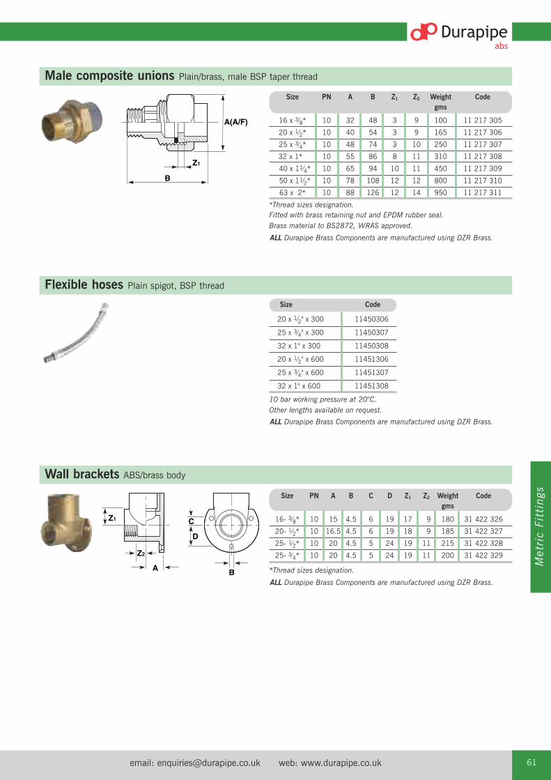
email: [email protected] web: www.durapipe.co.uk 61
Metric Fittings
Male composite unions Plain/brass, male BSP taper thread
Wall brackets ABS/brass body
B
Z1
A(A/F)
BA
Z2
Z1 C
D
Size PN A B Z1 Z2 Weight Code gms
16 x 3⁄8* 10 32 48 3 9 100 11 217 305
20 x 1⁄2* 10 40 54 3 9 165 11 217 306
25 x 3⁄4* 10 48 74 3 10 250 11 217 307
32 x 1* 10 55 86 8 11 310 11 217 308
40 x 11⁄4* 10 65 94 10 11 450 11 217 309
50 x 11⁄2* 10 78 108 12 12 800 11 217 310
63 x 2* 10 88 126 12 14 950 11 217 311
*Thread sizes designation.Fitted with brass retaining nut and EPDM rubber seal.Brass material to BS2872, WRAS approved.
Size PN A B C D Z1 Z2 Weight Code gms
16- 3⁄8* 10 15 4.5 6 19 17 9 180 31 422 326
20- 1⁄2* 10 16.5 4.5 6 19 18 9 185 31 422 327
25- 1⁄2* 10 20 4.5 5 24 19 11 215 31 422 328
25- 3⁄4* 10 20 4.5 5 24 19 11 200 31 422 329
*Thread sizes designation.
Size Code
20 x 1⁄2" x 300 11450306
25 x 3⁄4" x 300 11450307
32 x 1" x 300 11450308
20 x 1⁄2" x 600 11451306
25 x 3⁄4" x 600 11451307
32 x 1" x 600 11451308
10 bar working pressure at 20°C.Other lengths available on request.
Flexible hoses Plain spigot, BSP thread
ALL Durapipe Brass Components are manufactured using DZR Brass.
ALL Durapipe Brass Components are manufactured using DZR Brass.
ALL Durapipe Brass Components are manufactured using DZR Brass.

Tel: +44 (0)1543 279909 Fax: +44 (0)1543 27945062
B
AK
L
B
D
Z1
A
Flanges stub Plain serrated
Flanges blanking
Size PN A B D Z1 Weight gms Code
16 10 29 17 6 3 5 11 135 305 20 10 34 20 6 3 8 11 135 306 25 10 41 22 7 3 13 11 135 307 32 10 50 26 7 3 19 11 135 308 40 10 61 30 8 3 36 11 135 309 50 10 73 35 8 3 60 11 135 310 63 10 90 42 9 4 100 11 135 311 75 10 106 49 10 4 150 11 135 312 90 10 125 59 11 6 240 11 135 313 110 10 149 68 12 6 370 11 135 314 125 10 165 76 13 5 520 11 135 315 140 10 180 83 14 7 680 11 135 316 160 10 205 93 16 5 930 11 135 317 200* 10 252 114 17 6 1520 11 135 318 225 10 273 126 24 6 1360 11 135 319 250 10 306 140 20 9 2140 11 135 320 315 10 375 180 32 14 5000 11 135 323
DIN 2501 16 bar/PN16No. Weight
Size PN A B K L Holes gms Code
32 10 116 13 85 14 4 139 11 323 30840 10 141 13 100 18 4 204 11 323 30950 10 153 13 110 18.5 4 237 11 323 31063 10 166 19 124 18 4 447 11 323 31175 10 186 19 145 18.5 4 568 11 323 31290 10 201 19 159 18 8 645 11 323 313110 10 221 26 180 18 8 715 11 323 314125 10 251 26 210 18 8 1338 11 323 315140 10 251 26 210 18 8 1338 11 323 316160 10 286 27 240 23 8 1720 11 323 317
*The 200mm (NW175) stub flange supplied by Durapipe when used inconjunction with backing ring; code number 421 318 and 420 318 has abolt circle diameter which matches 225mm (NW200) flanges (295mm PCD).
Note: Durapipe backing rings must be used in conjunction with blank flanges.

email: [email protected] web: www.durapipe.co.uk 63
Metric Fittings
Drilled to ANSI CLASS 150 No. Weight Size A B C P L Holes gms Code
20 90 8 28 61 16 4 300 13 448 306 25 100 8 34 70 16 4 380 13 448 307 32 110 9 42 79 16 4 480 13 448 308 40 118 8 51 90 16 4 530 13 448 309 50 129 8 63 99 16 4 590 13 448 310 63 154 10 78 121 19 4 1050 13 448 311 90 192 11 110 153 19 4 1470 13 448 313 110 230 11 133 190 19 8 2080 13 448 314
B
AC P
L
Backing rings Galvanised mild steelDrilled to DIN 2501 (BS4504) PN10/PN16 No. Weight Size A B C P L Holes gms Code
16 90 7 23 61 14 4 240 13 421 305 20 96 6 28 65 14 4 300 13 421 306 25 106 7 34 75 14 4 320 13 421 307 32 116 7 42 85 14 4 350 13 421 308 40 142 7 51 100 18 4 420 13 421 309 50 152 7 62 110 18 4 710 13 421 310 63 165 8 78 125 18 4 1010 13 421 311 75 186 9 92 145 18 4 1280 13 421 312 90 201 9 110 160 18 8 1380 13 421 313 110 220 9 133 180 18 8 1430 13 421 314 125 253 8 150 210 18 8 1960 13 421 315 140 251 11 167 210 18 8 2060 13 421 316 160 286 11 190 240 22 8 2700 13 421 317
Drilled to DIN 2501 (BS4504) PN16 No. Weight Size A B C P L Holes gms Code
200* 340 11 235 295 22 12 3830 13 420 318 225 340 11 249 295 22 12 3190 13 420 319 250 405 20 278 355 26 12 9450 13 420 320 315 460 20 355 410 26 12 8400 13 420 323
Drilled to DIN 2501 (BS4504) PN10 No. Weight Size A B C P L Holes gms Code
200* 340 11 235 295 22 8 3830 13 421 318 225 340 11 249 295 22 8 3190 13 421 319 250 396 20 278 350 22 12 9450 13 421 320 315 448 20 355 402 22 12 8400 13 421 323
*The 200mm (NW175) stub flange supplied by Durapipe when used inconjunction with backing ring; code number 421 318 and 420 318 has a boltcircle diameter which matches 225mm (NW200) flanges (295mm PCD).

Tel: +44 (0)1543 279909 Fax: +44 (0)1543 27945064
B
A
Flat gaskets for use with stub flanges Weight EPDM Size A B gms Code
16 29 3.0 2 13 411 305 20 34 3.5 2 13 411 306 25 41 3.5 3 13 411 307 32 50 3.0 4 13 411 308 40 60 3.0 4 13 411 309 50 72 3.3 5 13 411 310 63 90 4.0 10 13 411 311 75 106 3.0 20 13 411 312 90 125 3.1 30 13 411 313 110 150 4.0 40 13 411 314 125 166 4.0 50 13 411 315 140 180 4.0 60 13 411 316 160 205 4.0 70 13 411 317 200 253 4.0 120 13 411 318 225 274 3.8 165 13 411 319 250 306 4.0 170 13 431 320 280 330 4.0 190 13 411 321 315 379 4.2 220 13 411 323
CM
L
EB
P
Valve support plates Galvanised steelDIN 2501 16 bar/PN16 No. Weight Size B C E L M N P Holes gms Code
16 91 84 50 14 16 2 61 4 370 31 459 305 20 97 86 49 14 16 2 65 4 640 31 459 306 25 105 89 76 14 16 2 75 4 750 31 459 307 32 114 96 77 14 12 2 85 4 860 31 459 308 50 150 125 100 14 22 2 110 4 1480 31 459 310 63 160 134 100 14 24 2 125 4 2100 31 459 311 75 185 144 125 14 22 2 145 4 2500 31 459 312 90 203 150 127 14 23 2 160 8 2660 31 459 313 110 214 160 150 14 22 3 179 8 2960 31 459 314
N = No. of holes in base.
O-Ring sockets Galvanised steel
Weight EPDM FPM Size ID B gms Code Code
16 15.54 2.62 23 23 209 305 23 211 305 20 20.22 3.53 39 23 209 306 23 211 306 25 28.17 3.53 68 23 209 307 23 211 307 32 32.93 3.53 94 23 209 308 23 211 308 40 40.65 5.34 163 23 209 309 23 211 309 50 47.00 5.34 190 23 209 310 23 211 310 63 59.69 5.34 355 23 209 311 23 211 311
Note: O-Rings EPDM.Not end load resistant - for buried pipework only.

email: [email protected] web: www.durapipe.co.uk 65
Metric Fittings
VKD Double union ball valves Manual – EPDM seals
Options:FPM seals (plain ends) order H0 DKB ***
For threaded versions refer to Imperial Valves section.
Manual valves can be supplied with locking kits - further information is available from ourValve Department.
T port configuration
L port configuration
Options:FPM seals (plain ends) order H0 DKB***
d DN PN L Z H E B C Weight gms Code
16 10 16 14 75 103 55 49 66 200 H0 DKA 305
20 15 16 16 71 103 55 49 66 195 H0 DKA 306
25 20 16 19 77 115 66 59 75 310 H0 DKA 307
32 25 16 22 84 128 75 66 85 440 H0 DKA 308
40 32 16 26 94 146 87 75 97 645 H0 DKA 309
50 40 16 31 102 164 100 87 110 880 H0 DKA 310
63 50 16 38 123 199 122 101 134 1490 H0 DKA 311
VKD & TKD ball valves can be supplied electrically or pneumatically actuated.
d DN PN Z L H H1 E B B1 C C1 gms Code
75 65 16 147 44 235 133 164 164 87 225 175 4380 H0 DKA 312
90 80 16 168 51 270 149 203 177 105 327 272 7200 H0 DKA 313
110 100 16 186 61 308 167 238 195 129 385 330 11141 H0 DKA 314
TKD 3-way ball valves Manual – EPDM seals
Options:FPM seals (plain ends) order H0 TTB***FPM seals (threaded ends) order H0 TTB***
Manual valves can be supplied with locking kits - further information is available from ourValve Department.
d DN PN H Z C C1 B B1 gms Code
20 15 16 118 86 67 40 54 29 310 H0 TTA 306
25 20 16 145 107 85 49 65 34.5 550 H0 TTA 307
32 25 16 160 116 85 49 65.9 39 790 H0 TTA 308
40 32 16 188.5 136.5 108 64 82.5 46 1275 H0 TTA 309
50 40 16 219 157 108 64 89 52 1660 H0 TTA 310
63 50 16 266.5 190.5 134 76 108 62 2800 H0 TTA 311
d DN PN H Z C C1 B B1 gms Code
20 15 16 118 86 67 40 54 29 310 H0 LTA 306
25 20 16 145 107 85 49 65 34.5 550 H0 LTA 307
32 25 16 160 116 85 49 65.9 39 790 H0 LTA 308
40 32 16 188.5 136.5 108 64 82.5 46 1275 H0 LTA 309
50 40 16 219 157 108 64 89 52 1660 H0 LTA 310
63 50 16 266.5 190.5 134 76 108 62 2800 H0 LTA 311
Options:FPM seals (plain ends) order H0 LTB***
Valves Premium QualityValve for Demanding
Environments
Premium QualityValve for Demanding
Environments
Premium QualityValve for Demanding
Environments
Premium QualityValve for Demanding
Environments

Tel: +44 (0)1543 279909 Fax: +44 (0)1543 27945066
UC Ball check valves EPDM seals
WeightSize L Z C E gms Code
20 17 48 82 50 96 H0 UCA 30625 19 55 93 59 99 H0 UCA 30732 22 62 106 68 145 H0 UCA 30840 26 75 127 80 234 H0 UCA 30950 31 84 146 96 357 H0 UCA 31063 38 99 175 116 937 H0 UCA 311
Options:FPM seals (plain ends) order H0 UCB***
For threaded versions refer to Imperial Valves section.
UA Air release valves EPDM seals
WeightSize L Z C E gms Code
20 17 48 82 50 96 H0 UAA 306 25 19 55 93 59 99 H0 UAA 307 32 22 62 106 68 145 H0 UAA 30840 26 75 127 80 234 H0 UAA 30950 31 84 146 96 357 H0 UAA 31063 38 99 175 116 937 H0 UAA 311
Options:FPM seals (plain ends) order H0 UAB***
For threaded versions refer to Imperial Valves section.
Note: this valve must be installed at a minimum distance of 10 x nominal diameter (eg. 20" for size 63mm) from pump flange.
EV Double union ball valves Manual – EPDM seals
Weightd DN PN L Z C E H B gms Code
20 15 10 17 47 81 50 50 57 95 H0 EVA 306
25 20 10 19 51 95 59 55 66 156 H0 EVA 307
32 25 10 22 61 105 68 66.5 75 228 H0 EVA 308
40 32 10 31 84 146 96 93 103 540 H0 EVA 309
50 40 10 31 84 146 96 93 103 540 H0 EVA 310
63 50 10 38 96 172 116 107 121 844 H0 EVA 311
For threaded versions refer to Imperial Valves section.

email: [email protected] web: www.durapipe.co.uk 67
Metric Fittings
RV Y-Type strainers Plain ends – EPDM seals
VM Diaphragm valves Manual – plain union ends – EPDM seals
Options:FPM diaphragm order H0 VMB***PTFE diaphragm order H0 VMC***
Manual Valves can be supplied with locking kits - further information is available fromour Valve Department.
d DN PN B B1 H h H1 J L gms Code
20 15 10 95 26 124 12 90 M6 16 700 H0 UMA 306
25 20 10 95 26 144 12 90 M6 19 700 H0 UMA 307
32 25 10 95 26 154 12 90 M6 23 700 H0 UMA 308
40 32 10 126 40 174 18 115 M8 27 1500 H0 UMA 309
50 40 10 126 40 194 18 115 M8 32 1500 H0 UMA 310
63 50 10 148 40 224 18 140 M8 39 2400 H0 UMA 311
75 65 10 225 55 284 23 215 M12 44 7000 H0 VMA 412
90 80 10 225 55 300 23 215 M12 51 7000 H0 VMA 413
110 100 10 295 69 350 23 250 M12 61 10500 H0 VMA 414
D DN PN A B E L Z H Fig. gms CodeGrey max
20 15 16 125 72 55 16 103 135 A 211 H0 UVA 306
25 20 16 145 84 66 19 120 158 A 358 H0 UVA 307
32 25 16 165 95 75 22 132 176 A 256 H0 UVA 308
40 32 16 190 111 87 26 155 207 A 733 H0 UVA 309
50 40 16 210 120 100 31 181 243 A 1095 H0 UVA 310
63 50 10 240 139 120 38 222 298 A 1843 H0 UVA 311
Options:FPM seals (plain ends) order H0 UVB ***
For threaded versions refer to Imperial Valves section.
PR Pressure relief valves EPDM seals
C
ZEG
B
A
D
F
Size PN Z A B C D E F G gms Code
20 10 92 143 20.5 35 124 M6 25 12 700 H0 PRA 406
25 10 106 143 20.5 35 144 M6 25 12 700 H0 PRA 407
32 10 108 143 25.0 35 154 M6 25 12 700 H0 PRA 408
40 10 120 204 36.0 50 174 M8 44.5 16 1500 H0 PRA 409
50 10 130 204 39.5 50 194 M8 44.5 16 1500 H0 PRA 410
63 10 146 219 49.0 50 224 M8 44.5 16 2400 H0 PRA 411
Options:FPM seals order H0 PRB***
*
*
*
*Note: 75mm, 90mm and 110mm are spigot ended.

Tel: +44 (0)1543 279909 Fax: +44 (0)1543 27945068
FK Butterfly valves Glass reinforced polypropylene with ABS disc
Size DN PN B2 B5 B6 G G1 G2 G3 gms U Z Code
75 65 10 80 174 146 48 135 39 125 2400 4 46 HV FKA 10890 80 10 93 188 160 48 135 39 125 2800 8 49 HV FKA 109110 100 10 107 202 174 48 135 39 125 3150 8 56 HV FKA 110140 125 10 120 222 194 48 144 39 200 4450 8 64 HV FKA 111160 150 10 134 235 207 48 144 39 200 5200 8 70 HV FKA 112225 200 10 161 287 256 65 204 60 200 9300 8 71 HV FKA 113250 250 10 210 317 281 88 236 76 250 18600 12 114 HV FKA 114315 300 8 245 374 338 88 236 76 250 25600 12 114 HV FKA 115
with gear box
lever operated
Options:FPM seals order HV FKB***
Options:FPM seals order H0 FKB***
Note: Lugged versions available to special order. Please refer to our Valve Departmentfor further details.
Valves can be supplied as electrically or pneumatically actuated. Contact our Valve department on 01543 272424 for further information.
d DN PN B2 B3 C C1 gms U Z Code
50 40 16 60 137 175 100 900 4 33 H0 FKA 10663 50 16 70 143 175 100 1080 4 43 H0 FKA 10775 65 10 80 164 272 110 1470 4 46 H0 FKA 10890 80 10 93 178 272 110 1870 8 49 H0 FKA 109110 100 10 107 192 272 110 2220 8 56 H0 FKA 110140 125 10 120 212 330 110 3100 8 64 H0 FKA 111160 150 10 134 225 330 110 3850 8 70 H0 FKA 112225 200 10 161 272 420 122 6750 8 71 H0 FKA 113
U = No. of holes
U = No. of holes

email: [email protected] web: www.durapipe.co.uk 69
Metric Fittings
Accessories
Cobra pipe clips
BG
C
A
D
Size A B C D G Bolt/Screw gms Code
*12 – 24 25 15 16 M4/3BA/No 8 5 13 434 304*16 – 35 25 17 16 M4/3BA/No 8 7 13 434 305*20 – 35 30 14 16 M5/1BA/No 10 8 13 434 306*25 – 35 35 16 17 M5/1BA/No 10 11 13 434 30732 65 45 40 17 17 M5/1BA/No 10 14 13 434 30840 75 45 45 20 20 M5/1BA/No 10 21 13 434 30950 85 50 50 22 21 M6/0BA/No 10 30 13 434 31063 102 60 60 19 21 M6/0BA/No 10 42 13 434 31175 122 70 70 27 31 M8 94 13 434 31290 148 80 90 39 31 M8 121 13 434 313110 171 90 96 36 35 M8 184 13 434 314125 204 144 132 40 40 M8 237 13 434 315140 211 156 132 40 40 M8 252 13 434 316160 243 170 150 40 40 M8 330 13 434 317
*Without retaining clips. Bolts/screws not supplied.
One-step solvent cement
Only Durapipe ABS solvent cement and Durapipe Eco-cleanershould be used for jointing of Durapipe ABS pipework systems.
Eco-cleaner Litres gms Code
0.5 500 03 457 395
Only Durapipe ABS solvent cement and Durapipe Eco-cleanershould be used for jointing of Durapipe ABS pipework systems.
Litres gms Code
0.5 550 03 461 395
1.0 1100 03 461 396
Rubber lined pipe clips
Size mm Thread Code
16 M10 FT PC 1600 20 M10 FT PC 2000 25 M10 FT PC 2500 32 M10 FT PC 3200 40 M10 FT PC 4000 50 M10 FT PC 5000 63 M10 FT PC 6300 75 M10 FT PC 7500 90 M10 FT PC 9000 110 M10 FT PC 1100 160 M10 FT PC 1601

Tel: +44 (0)1543 279909 Fax: +44 (0)1543 27945070
Chamfering and de-burring tools
Pipe cutters
Description Product code
E 16-25mm pipe inner and outer milling cutter tool FT 55 72 90
E 16-63mm pipe inner and outer milling cutter tool FT 55 65 12
32-160mm chamfering tool FT 55 05 10
Description Product code
16-63mm pipe cutter FT 80 00 01
50-125mm pipe cutter FT 80 00 03
16-63mm spare cutter wheel FT 80 00 02
50-125mm spare cutter wheel FT 80 00 04
Pipe trays
Pipe dia Standard length Standard pack Productmm in metres quantity in metres code
16 2 50 FT 635 21620 2 50 FT 635 22025 2 50 FT 635 22532 2 50 FT 635 232

PRE-INSULATED PIPEWORK
Duracool
Duracool is a completely innovative pre-insulated ABS pipework systemthat is specially designed to provide reduced installation costs.
Duracool is a complete system of pre-insulated pipe with unique shells for the fittings,
insulation is protected by an attractive polyethylene outer casing.
Fitting is quick and easy, eliminating the need for hot works or manual lagging and
making installation an easy and convenient process.
Key Product Information
• Size Range: 20mm to 225mm
• Pressure Rating: PN10
• Temperature Rating: -40°C to 70°C
Typical Applications
• Chilled water
• Glycol systems
• Brine
Key Product Features
• Lightweight
• Easy to install
• Cost-efficient installation
• Wide temperature range
• Tough and durable
Pre-insulated pipework

Pre-insulated pipework
Tel: +44 (0)1543 279909 Fax: +44 (0)1543 27945072
Duracool System Overview
Straight socket Elbow 90° Tee equal End cap
End cap
End cap
Elbow 90°
Elbow 90°
Elbow 90°
Elbow 90°
Elbow 90
End cap
Elbow 90°
Straightsocket
Straightsocket
Tee equal
TC tapeTo be used for joints
Not all products are included in this schematic.
NB: Pipe should be installed at
least 100mm from the wall in
order for tape to be passed
around.
Fields of Application:• Chilled water• Secondary refrigeration• Air conditioning• Industrial cold/iced water• Pharmaceutical industry• Food and beverage industry• Supermarkets• Chemical industry• Paper production
Advantages:• Easy-strip trimming forclean pipe ends
• Unique Thermo-Click shellsfor pipe fittings
• No hot works• No manual lagging• Lifetime cost savings• No corrosion• Top levels of energyefficiency
• Reduced costs for pipehanging and can be applieddirectly onto the casing
• Simple installation• Hygienic and aestheticallypleasing
• Joints can be opened forinspection.
• High mechanical strength• Resistant to chemicals and UV rays
need for hot works or manual lagging andallowing convenient, simple trimming. Acomplete system of pre-insulated pipe andunique Thermo-Click shells for fittings,insulation is provided by polyurethane foamprotected by an attractive polystyrene outercasing. The insulation is able to performalong the full temperature range of ABS andthe outer can live up to daily cleaning withvarious chemicals (max 50°C on the jacket).
We have various components which make itpossible for you to build a completeinsulated piping system. All our fittings aredelivered complete with the tape and sealantyou will need to complete the installation,more is available if needed.
Duracool is a custom designed insulatedpipework system that offers exceptionalperformance and life. It is the perfect additionto our standard ABS system which includespipe, fittings, valves and a full range oftransition fittings. Designed to enable lowerlifetime and operational costs.
The system can be used to both protect andinsulate the carrier pipe and when installedcorrectly can offer exceptional performancecompared to any type of standard insulation and is therefore ideal for the transportation of chilled water, iced water, salt solutions, glycol solutions and organic salt solutions. Thermo-Click shells are watertight,condensation proof and suitable for outsideuse. Fitting is quick and easy, eliminating the

email: [email protected] web: www.durapipe.co.uk 73
Pre-insulated pipework
Duraco
ol
To avoid unnecessary problems please examine the following before planning/installation of Duracool.
Technical Considerations when Installing Duracool
There is a minimum distance required between two 90° elbows, if your requirements fallbetween H min and H max then standard un-insulated pipe can be used between the elbows.
Sealants for use with Duracool
All Duracool Thermo-Click shells are supplied with the sealant required to make a joint. The sealantsupplied has been tested and approved for use with ABS pipework. However, certain Intumescentmastics, mastic sealants and silicone sealants are formulated with components that can be hazardouswhen in contact with ABS, such as phthalates. Therefore confirmation of the suitability of any masticsealant should be determined before being used in conjunction with ABS pipework or Duracool.
OD of H min H maxOuter Pipe (mm) (mm)
(mm)
90 220 500110 290 560125 340 590140 370 650160 430 710180 440 740200 480 720225 536 830250 604 910280 660 900315 634 910

Pre-insulated pipework
Tel: +44 (0)1543 279909 Fax: +44 (0)1543 27945074
When you receive your Thermo-Click shells you will also receive the appropriate amount of sealant and tape to completethe installation. Please see note on page 71.
*Tees are supplied standard with an L dimension of 440mm,but 875mm product is available as a special order, pleaseenquire for details.
Installation of Thermo-Click Shells
Carrier pipe Thermo-Click d mm Diameter L max L min
D (mm)25, 32 90 250 11040, 50 110 280 14563 125 295 17075 140 325 18590 160 355 215110 200 360 240140 225 415 268160 250 455 302225 315 455 317
Carrier pipe Thermo-Clickd mm Diameter L max L2 min
D (mm)25, 32 90 23040, 50 110 23063 125 23075 140 26090 160 265110 200 285140 225 285160 250 260225 315 275
440or
875*

email: [email protected] web: www.durapipe.co.uk 75
Pre-insulated pipework
Duraco
ol
1. The pre-insulated pipe is supplied with a spigot of carrier pipeprotruding from the end of the insulation. This is to make theinstallation as quick and simple as possible. However, if yourinstallation does not require full lengths you will need toperform the following.
2. Determine the length of pipe you require and cut through theouter skin, insulation and carrier pipe to the required distance.
Duracool Pipe Preparation
3. Perform a shallow cut around the pipe at the required distancefrom the end of the pipe, so that the outer skin can be removed(the distance will be dependent on the type of fitting that isbeing installed (please refer to the tables on page 72).
4. With a blunt instrument remove the remaining insulation so asto reveal the carrier pipe. There is a thin ‘easy-peel’ polythenelayer between the insulation and the pipe to make this easier.
5. Use the appropriate fitting to make the joint, this is describedon pages 16-18 of this technical catalogue. Compete this forthe full system and perform a pressure test while all of thejoints are exposed, so that any leaks can be identified and fixed.
6. Cut the Thermo-Click insulation shells to fit tight between the jacketed pipe and Thermo-Click shells. The plastic edge 25-30mm on the Thermo-Click shells must be removed.
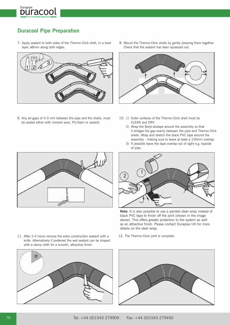
Pre-insulated pipework
Tel: +44 (0)1543 279909 Fax: +44 (0)1543 27945076
Duracool Pipe Preparation
9. Any air-gaps of 0-3 mm between the pipe and the shells, mustbe sealed either with mineral wool, PU-foam or sealant.
10. 1) Outer surfaces of the Thermo-Click shell must be CLEAN and DRY.
2) Wrap the Butyl-alutape around the assembly so that it bridges the gap evenly between the pipe and Thermo-Click shells. Wrap and stretch the black PVC tape around the assembly - making sure to leave at least a 100mm overlap.
3) If possible leave the tape overlap out of sight e.g. topside of pipe.
7. Apply sealant to both sides of the Thermo-Click shell, in a levellayer, ø8mm along both edges.
11. After 2-4 hours remove the extra construction sealant with aknife. Alternatively if preferred the wet sealant can be shapedwith a damp cloth for a smooth, attractive finish.
12. The Thermo-Click joint is complete.
Note: It is also possible to use a painted steel wrap instead ofblack PVC tape to finish off the joint (shown in the imageabove). This offers greater protection to the system as well as an attractive finish. Please contact Durapipe UK for moredetails on the steel wrap.
8. Mount the Thermo-Click shells by gently pressing them together.Check that the sealant has been squeezed out.

email: [email protected] web: www.durapipe.co.uk 77
Pre-insulated pipework
Duraco
ol
This polyurethane system has been specially formulated for production of half shells. The waterbased foam has a fine cell structure,which results in a high strength. The system does not contain any HCFC – it is blown with CO2 – and therefore has zero Ozonedepletion potential (ODP).
Foam Characteristics at 20°C (hand mixed)
Properties Value Test MethodDensity, free rise: 43kg/m³ BS 4370 part 1 meth. 2Density (packed in form) 88kg/m³ BS 4370 part 1 meth. 2
Closed cells 96% ISO 4590
Cell size < 0.2mm EN253Water absorption 2.2 % EN253
Parallel to rise 0.31MPa ISO 844Perpendicular to rise 0.16MPa ISO 844
E-modulus:Parallel to rise 11.7MPa ISO 844Perpendicular to rise 3.9MPa ISO 844
Dimensional stability:(+140ºC/0.02 MPa/48h) < - 5 % DIN 18159-1
Thermal conductivity coefficient:λ10 0,026 W/m°K ISO 8301λ24 0,027 W/m°K ISO 8301λ50 0,030 W/m°K ISO 8301
In Heat Transfer λ is used to denote the heat of vaporisation per mole or latent heat. Burning characteristics: B2 DIN 4102.
Thermo-Click shell outer‘Athpol’ P90UV - extruded UV stabilised high-impact polystyrene (HIPS) sheet.
The following information represents typical property values that are based on information given by polymer raw material suppliers.
Properties Value Test Method
MechanicalTensile Stress at Yield 23MPa ISO 527Flexural Strength 32MPa ISO 178Izod Impact Strength (notched) 23°C 12KJ/M2 ISO 180A
ThermalHeat Deflection Temperature (1.8MPa) 75°C ISO 75Vicat Softening Temperature (5kg - 50c/H) 84°C ISO 306
Density 1.02 ISO 1183Flammability at 1.6mm thickness HB UL94
Chemical Resistance ChartAcids, Inorganic Alcohols E- Weak E Aliphatic Amines E- Strong E Bases E- Strong oxidising F Polyglycols E
Acids, Organic Vegetable oils G- Weak E Pharmaceuticals E- Strong G Salts E
E = Excellent resistant - no attack.G = Good resistant - minor attack.F = Fair - limited resistance. Suitable for short term use only.
Data Sheet Thermo-Click Insulation Shells

Pre-insulated pipework
Tel: +44 (0)1543 279909 Fax: +44 (0)1543 27945078
Duracool Product Range
Pre-Insulated ABS pipe Free spigot end for solvent welding
Carrier Wall Thickness Length Pipe OD CodePipe size of Carrier Pipe (m) (mm)(mm) (mm)
25 1.9 5 90 21 555 307
32 2.1 5 90 21 555 308
40 2.7 5 110 21 555 309
50 3.4 5 110 21 555 310
63 4.2 5 125 21 555 311
75 5 5 140 21 555 312
90 6 5 160 21 555 313
110 7.3 5 200 21 555 314
140 9.3 5 225 21 555 316
160 10.5 5 250 21 555 317
200 13.2 5 280 21 555 318
225 14.8 5 315 21 555 319
Socket straights Thermo-Click Shells
Carrier Pipe Length Thermo-Click CodeSize d (mm) L (mm) D (mm)
25 440 90 21 100 313
32 440 90 21 100 313
40 440 110 21 100 314
50 440 110 21 100 314
63 440 125 21 100 315
75 440 140 21 100 316
90 440 160 21 100 317
110 440 200 21 100 318
140 440 225 21 100 319
160 440 250 21 100 320
225 440 315 21 100 323
Elbows 90° Thermo-Click Shells
Carrier Pipe Dimension Thermo-Click OD CodeSize d (mm) E (mm) D (mm)
25 250 90 21 115 313
32 250 90 21 115 313
40 275 110 21 115 314
50 275 110 21 115 314
63 295 125 21 115 315
75 325 140 21 115 316
90 355 160 21 115 317
110 360 200 21 115 318
140 410 225 21 115 319
160 425 250 21 115 320
225 450 315 21 115 323
Note: ABS Fittings to be ordered separately.
Note: ABS Fittings to be ordered separately.

email: [email protected] web: www.durapipe.co.uk 79
Pre-insulated pipework
Duraco
ol
Note: ABS Fittings to be ordered separately.
Duracool Product Range
Elbows 45° Thermo-Click Shells
Tee equal Thermo-Click Shells
Carrier Pipe Dimension Dimension Thermo-Click OD CodeSize d (mm) G (mm) H (mm) D (mm)
25 440 250 90 21 122 313
32 440 250 90 21 122 313
40 440 260 110 21 122 314
50 440 260 110 21 122 314
63 440 260 125 21 122 315
75 440 290 140 21 122 316
90 440 310 160 21 122 317
110 440 325 200 21 122 318
140 440 320 225 21 122 319
160 440 315 250 21 122 320
225 440 350 315 21 122 323
End caps Thermo-Click Shells
Carrier Pipe Thermo-Click OD Dimension (m) CodeSize d (mm) pipe d (mm) D (mm)
25 90 60 21 149 313
32 90 60 21 149 313
40 110 60 21 149 314
50 110 60 21 149 314
63 125 60 21 149 315
75 140 60 21 149 316
90 160 60 21 149 317
110 200 60 21 149 318
140 225 60 21 149 319
160 250 60 21 149 320
225 315 60 21 149 323
Note: ABS Fittings to be ordered separately.
Carrier Pipe Dimension Thermo-Click OD CodeSize d (mm) F (mm) (D) (mm)
25 250 90 21 119 313
32 250 90 21 119 313
40 260 110 21 119 314
50 260 110 21 119 314
63 260 125 21 119 315
75 290 140 21 119 316
90 310 160 21 119 317
110 325 200 21 119 318
140 320 225 21 119 319
160 315 250 21 119 320
225 350 315 21 119 323
Note: ABS Fittings to be ordered separately.

Pre-insulated pipework
Tel: +44 (0)1543 279909 Fax: +44 (0)1543 27945080
Tees 90° reducing Thermo-Click Shells
Carrier Pipe Dimension Dimension Thermo-Click OD Code Size d (mm) J (mm) K (mm) D (mm)
40 x 25 440 250 110 x 90 21 109 451
40 x 32 440 250 110 x 90 21 109 451
50 x 25 440 250 110 x 90 21 109 451
50 x 32 440 250 110 x 90 21 109 451
63 x 25 440 250 125 x 90 21 109 458
63 x 32 440 250 125 x 90 21 109 458
63 x 40 440 260 125 x 110 21 109 459
63 x 50 440 260 125 x 110 21 109 459
75 x 25 440 250 140 x 90 21 109 465
75 x 32 440 250 140 x 90 21 109 465
75 x 40 440 260 140 x 110 21 109 466
75 x 50 440 260 140 x 110 21 109 466
75 x 63 440 260 140 x 125 21 109 467
90 x 25 440 250 160 x 90 21 109 473
90 x 32 440 250 160 x 90 21 109 473
90 x 40 440 250 160 x 110 21 109 474
90 x 50 440 250 160 x 110 21 109 474
90 x 63 440 250 160 x 125 21 109 475
90 x 75 440 290 160 x 140 21 109 476
110 x 25 440 250 200 x 90 21 109 483
110 x 32 440 250 200 x 90 21 109 483
110 x 40 440 260 200 x 110 21 109 484
110 x 50 440 260 200 x 110 21 109 484
110 x 63 440 260 200 x 125 21 109 485
110 x 75 440 290 200 x 140 21 109 486
110 x 90 440 310 200 x 160 21 109 487
140 x 25 440 250 225 x 90 21 109 491
140 x 32 440 250 225 x 90 21 109 491
140 x 40 440 260 225 x 110 21 109 492
140 x 50 440 260 225 x 110 21 109 492
140 x 75 440 290 225 x 140 21 109 493
140 x 90 440 310 225 x 160 21 109 494
140 x 110 440 325 225 x 200 21 109 495
160 x 25 440 250 250 x 90 21 109 490
160 x 32 440 250 250 x 90 21 109 490
160 x 40 440 260 250 x 110 21 109 469
160 x 50 440 260 250 x 110 21 109 469
160 x 63 440 260 250 x 125 20 109 508
160 x 75 440 290 250 x 140 21 109 516
160 x 90 440 310 250 x 160 21 109 497
160 x 110 440 325 250 x 200 21 109 498
160 x 140 440 320 250 x 225 21 109 499
225 x 25 440 250 315 x 90 21 109 506
225 x 32 440 250 315 x 90 21 109 506
225 x 40 440 260 315 x 110 21 109 505
225 x 50 440 260 315 x 110 21 109 505
225 x 63 440 260 315 x 125 20 109 510
225 x 75 440 290 315 x 140 20 109 518
225 x 90 440 310 315 x 160 20 109 525
225 x 110 440 325 315 x 200 21 109 536
225 x 140 440 320 315 x 225 21 109 502
225 x 160 440 315 315 x 250 21 109 503
Note: ABS Fittings to be ordered separately.
Duracool Product Range

email: [email protected] web: www.durapipe.co.uk 81
Vulcathene• Safe chemical drainage • Two easy jointing methods - Mechanical or Enfusion • Ideal for schools, universities and colleges, hospitals and clinics, pharmaceutical and research organisations
Air-Line Xtra • High performance thermoplastic pipework system for compressed air
Polypropylene • Conveys chemicals at temperatures up to 100ºC• Excellent resistance to a wide range of substances• Available in larger diameters up to 500mm• Full range of valves
Corzan• Solvent weld thermoplastic pipe system for aggressive substances• Designed specifically for use in highly corrosive conditions at temperatures up to 95ºC• Valves range available
PVC-U• Versatile, multi-purpose solvent weld pipework system with an extensive range of valves and fittings• The established system for process and industrial handling of chemicals and water up to 60ºC• Guardian dual contained PVC-U pipework system
PLX• Purpose designed for safe fuel transfer• Suitable for pressure and vacuum applications • Resists fuel permeation
Durapipe UK Pipework Systems
Flow Control• Manual and actuated flow control solutions • For use with all Durapipe systems • Lightweight and easy to install
ABS• Ideal for chilled, potable and waste water• Tough, durable, lightweight and fully approved• Suitable for use from -40°C to +70°C• Fully matched system of pipes, fittings and valves

Tel: +44 (0)1543 279909 Fax: +44 (0)1543 27945082
1. DEFINITIONS:‘Seller’ shall mean Glynwed Pipe Systems Limited, registered in England under number1698059. ‘Buyer’ shall mean any company, organisation or individual to whom a quotationis offered, or whose order is accepted by the Seller.
2. CONDITIONS:All offers, quotations, estimates, acceptances and contracts are subject to theseConditions of Business and any terms or conditions which any other person shall seek toimpose or make part of any contract shall, so far as is inconsistent with these Conditionsof Business, not apply unless expressly agreed by the Seller in writing. The headings inthese conditions are for convenience only and shall not affect their interpretation.
3. QUOTATIONS AND PRICE VARIATION:a) Any quotation given by the Seller is an invitation to the Buyer to make an offer only andno order of the Buyer placed with the Seller in pursuance of a quotation or otherwise shallbe binding on the Seller unless and until it is accepted in writing by the Seller.
b) Unless stated otherwise, all quotations and published price lists are ex works, exclusiveof VAT and shall remain valid for 30 days or such a period as may be quoted butnevertheless the Seller may amend or withdraw any quotation by written or oral notice.Quotations may be varied if the Buyer makes variations in his specifications.
4. STATEMENTS OR REPRESENTATIONS TO THE BUYER:If any statement or representation has been made to the Buyer upon which the Buyerrelies other than in the documents enclosed with the Seller's quotation, the Buyer must setout that statement or representation in a document to be attached to or endorsed on theorder in which case the Seller may submit a new quotation.
5. DELIVERY - TIME:a) Any period for delivery given at any time and in any manner by the Seller is an estimateonly and is not binding on the Seller. Delivery periods are normally calculated from thelater of:
i) acceptance of order; or
ii) where applicable, the receipt by the Seller of a detailed specification or drawings.
b) Time shall not be deemed to be of the essence of the contract. Failure by the Seller tomeet any quoted delivery period for any part or the whole of the order shall not entitle theBuyer to rescind the contract or to claim damages of any nature.
c) The Seller will endeavour to comply with reasonable requests by the Buyer forpostponement of delivery but shall be under no obligation to do so. Where delivery ispostponed otherwise than due to default by the Seller the Buyer shall pay all costs andexpenses including a reasonable charge for storage and transportation occasionedthereby and an extra charge for split delivery if applicable.
d) The Buyer will receive delivery of any consignment between the hours of 8.00am and4.00pm Monday to Friday inclusive, unless otherwise agreed in writing. Cost incurred bythe Seller arising from the Buyer's refusal to accept consignments within the agreed hoursshall be borne by the Buyer.
6. DELIVERY AND RISK:a) Except where stated to the contrary in the contract, delivery shall be made as follows:
i) where the Buyer provides the transport, delivery shall be made ex the Seller's works;
ii) where the Seller provides the transport, delivery shall be made to the premises of theBuyer, or the premises of the Buyer's customer or works site if the Buyer has requested delivery to be so made but where the Buyer has made such a request the Seller will make a first delivery to the Buyer's customer or works site as so much of the goods as is available for that delivery but subsequent deliveries will be made to the premises of the Buyer.
b) The Seller may at its discretion make partial delivery of orders and invoice the same.
c) Risk in the goods shall pass on delivery.
d) Where goods are sent FOB the Seller's responsibility shall cease when the goods areplaced on board ship or aircraft without the need for the Seller to give notice to the Buyerand the provisions of Section 32(3) of the Sale of Goods Act 1979 shall not apply.
7. OWNERSHIP OF GOODS:a) The goods shall remain the sole and absolute property of the Seller as legal andequitable owner until such time as the Buyer shall have paid to the Seller the contract pricetogether with the full price of any other goods the subject of any contract between theSeller and the Buyer.
b) The Buyer acknowledges that until such time as the property in the goods passes to theBuyer he is in possession of the goods as a bailee and fiduciary agent for the Seller andthe Purchaser shall store the goods in such a manner that they are clearly identifiable asthe property of the Seller.
c) Until payment due under all contracts between the Buyer and the Seller had been madein full, in the event of sale of the goods by the Buyer:
i) the Seller shall be entitled to trace all proceeds of sale received by the Buyer through any bank or other account maintained by the Buyer; and
ii) the Buyer shall if requested by the Seller in writing to so assign its rights to recover theselling price of the goods from the third parties concerned. Such monies to be held separately by the Buyer as agent on behalf of the Seller.
d) The Seller may for the purpose of recovery of its goods enter upon any premises wherethey are stored or where they are reasonably thought to be stored and may repossess thesame.
8. TERMS OF PAYMENT:In the event of default in payment according to the agreed payment terms between theSeller and the Buyer – ie: by the end of the month following the month of despatch of thegoods the Seller shall be entitled without prejudice to any other right or remedy to suspendall further deliveries and to charge interest on any amount outstanding at the rate of 2%per month until payment in full is made (a part of a month being treated as a full month forthe purpose of calculating interest).
9. SHORTAGES AND DEFECTS APPARENT ON DELIVERY:a) It shall be the responsibility of the Buyer to inspect or arrange for an inspection of thegoods on delivery whether the goods are delivered to the Buyer's premises or to thepremises of the Buyer's customer or to a works site. If no such inspection is made theBuyer shall be deemed to have accepted the goods.
b) The Buyer shall have no claim for shortages or defects apparent on inspection unless:
i) a written complaint is made to the Seller within three days of receipt of the goods specifying the shortage or defect; and
ii) the Seller is within seven days of receipt of the complaint given an opportunity to inspect the goods and investigate the complaint before any use is made of the goods.
c) If a complaint is not made to the Seller as herein provided then in respect of suchshortages or defects the goods shall be deemed to be in all respects in accordance withthe contract and the Buyer shall be bound to pay for the same accordingly.
10. CLAIMS FOR DEFECTS NOT APPARENT ON INSPECTION:a) The Buyer shall have no claim for defects not apparent on inspection unless the Selleris notified of defective workmanship or materials within twelve months from delivery of thegoods. Provided that the goods have been installed and applied in accordance with anyrelevant recommendations made by the Seller, the Seller will at its option replace thegoods or refund the net invoiced price in respect of the goods which have been shown tobe defective. If the Seller does so supply substitute goods the Buyer shall be bound toaccept such substituted goods in full satisfaction of the obligations of the Seller under thecontract.
b) The Buyer shall in any event have no claim or set-off in respect of defects unless awritten complaint is sent to the Seller as soon as the defect is noticed and no use is madeof the goods thereafter or alteration made thereto by the Buyer before the Seller is givenan opportunity to inspect the goods.
c) The Buyer is responsible for ensuring that the goods are fit for any particular purpose,and no warranty or condition of fitness for any particular purpose is to be implied into thecontract.
11. LIABILITY:Save as stated in Conditions 9 and 10 (and save in respect of death or personal injuryresulting from the negligence of the Seller its servants or agents) the Seller shall not beliable for any claim or claims for direct or indirect consequential or incidental injury loss ordamage made by the Buyer against the Seller whether in contract or in tort (includingnegligence on the part of the Seller its servants or agents) arising out of or in connectionwith any defect in the goods or their fitness or otherwise for any particular purpose or anyact omission neglect or default of the Seller its servants or agents in the performance ofthe contract.
12. FORCE MAJEURE:Notwithstanding anything herein contained neither the Buyer nor the Seller is to be heldliable for any delay or failure to carry out the contract due wholly or in part to an act of Godaction by any Government whether British or foreign civil war strikes and/or lockoutswheresoever occurring fire trade disputes floods or unfavourable weather or any materialbecoming unavailable or irreplaceable (whether at all or at commercially acceptableprices) or any other circumstances beyond the control of the Seller.
13. SUB-CONTRACTING:The Seller reserves the right to sub-contract the fulfilment of any order or any part thereof.
14. INSOLVENCY AND BREACH OF CONTRACT:In the event that:
a) the Buyer commits any breach of the contract and fails to remedy such breach (if capable of remedy) within a period of thirty days from receipt of a notice in writing fromthe Seller requesting such remedy; or
b) any distress or execution is levied upon any of the goods or property of the Buyer; or
c) the Buyer offers to make any arrangements with or for the benefit of its creditors or (if an individual) becomes subject to a petition for a bankruptcy order or (being a limitedcompany) has a receiver appointed of the whole or any part of its undertaking property orassets; or
d) an order is made or a resolution is passed or analogous proceedings are taken for thewinding up of the Buyer (save for the purpose of reconstruction or amalgamation withinsolvency and previously approved in writing by the Seller) the Seller shall thereupon beentitled without prejudice to its other rights hereunder forthwith to suspend all furtherdeliveries until the default has been made good or to determine the contract and anyunfulfilled part thereof or at the Seller's option to make partial deliveries. Notwithstandingany such termination the Buyer shall pay to the Seller at the contract rate for all the goodsdelivered up to and including the date of termination.
15. INDUSTRIAL PROPERTY RIGHTS:If goods supplied by the Seller to the Buyer's design or specifications infringe or arealleged to infringe any patent or registered design right or copyright the Buyer willindemnify the Seller against all damages, costs and expenses incurred by the Seller as aresult of the infringement or allegation. The Buyer will give the Seller all possible help inmeeting any infringement claim brought against the Seller.
16. BUYER'S ERROR IN ORDERING:In the event the Buyer orders incorrectly the Seller will be under no obligation to the Buyerto rectify or assist in rectifying the error.
17. LAW AND JURISDICTION:The contract shall be subject in all respects to English Law and to the jurisdiction of theEnglish Courts.
DURAPIPE UK CONDITIONS OF SALE

Distributor
04900020 March 2010
Registered office:
Durapipe UKWalsall Road Norton CanesCannockStaffordshireWS11 9NSUnited KingdomTel: +44 (0)1543 279909Fax: +44 (0)1543 279450email: [email protected]: www.durapipe.co.uk
Durapipe UK reserves the right to modify the details in this publication as products and specifications are updated and improved.The content of this publication is for general information only and it is the user’s responsibility to determine the suitability of any productfor the purpose intended.
For further information on all Durapipe UK products and services contact our Customer Services Department as detailed below.
Customer Services Tel: 01543 273100 Fax: 0800 317875
Durapipe UK is a trade name of Glynwed Pipe Systems Ltd. Company Number 1698059.