impeller design and multi-stage architecture optimisation
TRANSCRIPT

Impeller design and multi-stage architecture optimisation forturbocompressors operating with a helium-neon gas mixture
Maxime Podeur*1, Damian M. Vogt1, Sebastiano Mauri2, Philipp Jenny2
1Institute of Thermal Turbomachinery (ITSM), University of Stuttgart, Pfaffenwaldring 6, Stuttgart 70550, Germany2MAN Energy Solutions Schweiz AG
ABSTRACTAs part of the design of a new particle accelerator at CERN, a
research is conducted to study the challenges and opportunities ofmulti-stage turbocompressor machines operating with light gasesand more specifically with a mixture of helium and neon. First, a 1Dstage performance prediction model is implemented and coupledwith a genetic algorithm in order to generate an impeller database.Then, a stacking method is developed considering design philoso-phies and technological limitations observed in the industry. Thismodel is coupled with a second loop of the same genetic algorithm,which provides multi-stage architectures optimised for either com-pactness, i.e. number of stages, or efficiency. For both objectives,an ideal number of stages can be determined which increases signif-icantly as the operating gas becomes lighter. The impellers diversitywithin the database also plays an important role on the overall ma-chine architecture. Finally, in alignment with potential technologi-cal improvements, the motor maximum rotational speed is varied tostudy the achievable reduction in the required number of stages.
NOMENCLATUREA, B, C, D, H and G, n = coefficients in equation [-]A1 = inlet flow area [m2]a = speed of sound [m/s]BL = blade loading [-]D2 = impeller tip diameter [m]D1s = impeller inlet shroud diameter [m]D1h = impeller inlet hub diameter [m]Deq = diffusion factor [-]h2 = blade exit width [m]k = impeller shape factor
(1− (D1h/D1s)
2))
[-]
MU2= impeller tip Mach number (U2/
√γRTt1) [-]
m = mass flow rate [kg/s]V1 = inlet volume flow rate [m3/s]OM = operating margin [-] ((mc − ms)/mc)P = pressure [Pa], penalty [-]T = temperature [K], TeslaU2 = impeller tip speed [m/s]xHe = mole fraction of helium [-]Z = number of blades [-]
Greek Symbolsα = absolute flow angle [◦]β = relative flow angle [◦]β ′ = solid blade angle [◦]η = efficiency [-]γ = isentropic exponent [-]λ = work input coefficient (Δh/U2
2 ) [-]Ω = rotational speed [RPM]ψ = pressure rise coefficient (ηλ ) [-]φt1 = inlet flow coefficient (m/ρt1D2
2U2) [-]
φ2 = outlet flow coefficient (Cm2/U2) [-]Π = pressure ratio [-]
Subscripts1 = impeller inlet2 = impeller outletc = choked = designhigh = high rotational speedin = machine inletlow = low rotational speedob j = objectiveopt = optimalout = machine outletp = polytropicreq = requiredred = reducedre f = references = surge
INTRODUCTIONThe current research has been conducted within the framework of
a European project coordinated by CERN in Geneva, Switzerland.As recently advertised, the research centre is currently designing anew particle accelerator aiming at higher energy of particle collisionenabling to explore a new research space for the potential discoveryof unknown particles. To do so, the perimeter of the acceleratingloop as well as the magnetic field of the superconducting magnetsare increased to 100 km and 16 T respectively in comparison to itspredecessor, the so-called Large Hadron Collider (LHC) featuring a27-km perimeter and superconducting magnets reaching a magneticfield of 8 T. A schematic of the Future Circular Collider (FCC) isshown in Figure 1 and compared to the actual LHC.
Fig.1 Scheme of the Future Circular Collider (FCC)
With this novel accelerator architecture, the heat load on thecryogenic cycle used to maintain the superconducting magnet nearabsolute 0 K is significantly increased in comparison to the LHC.
International Journal of Gas Turbine, Propulsion and Power Systems October 2020, Volume 11, Number 4
Presented at International Gas Turbine Congress 2019 Tokyo, November 17-22, Tokyo, Japan Review Completed on July 9, 2020
Copyright © 2020 Gas Turbine Society of Japan
1

One of the objectives of the FCC cryogenic cycle is thus to replacethe original open loop pre-cooling cycle requiring a constant supplyof LN2 with a sustainable and efficient closed cycle with lowacquisition, operating and maintenance cost.
To address this objective, one promising solution is to use amixture of helium and neon, also called nelium, as the processgas. By adding neon, acting as a ballast gas, the use of multi-stageturbocompressor becomes economically more viable, especiallywhen looking at the required number of stages. In fact, whilestandard cycles operating with pure helium use screw compressorwith inherent low efficiencies to maintain the cost at a reasonablelevel, the addition of neon enables to reach higher overall machineefficiency and to increase significantly the maximum pressure ratioper turbocompressor stage. However, it is also worth noting thatadding neon implies several drawbacks, the first one being thegas cost in comparison to a pure helium configuration. Secondly,when neon is added, the gas heat conductivity decreases andother components, which are part of the cryogenic cycle such asheat exchangers or cold box, become larger. Consequently, themanufacturing of these large components could become hinderedor unaffordable. Finally, the theoretical maximal mole fractionof neon in the cycle is limited to 0.8 due to the presence of aliquid phase after the gas expansion for higher neon content.Nevertheless, the whole range of gas mixture, i.e. from pure heliumto pure neon, is taken into consideration hereafter to study theeffect of the widest diversity of fluid properties on the compressorarchitecture and performance.
The purpose of this paper is to focus on the compressor archi-tecture rather than to analyse the effect of the gas mixture over thedifferent cycle components. Hence, the following research aims atstudying the effect of the gas mixture and the available impellerson multi-stage machine architecture. To do so, an optimisationalgorithm is coupled with a model generating preliminary impellergeometries in order to build an impeller database. The sameoptimisation algorithm is subsequently coupled with a modelpredicting the performance of multi-stage machines. Finally, thedatabase is used to obtain an optimised multi-stage architecture forspecific boundary conditions.
In the literature, multiple references can be found to definegeometries and assess performances of radial compressor stagessuch as Aungier [1], Ludtke [2], Dixon [3], Casey and Rusch [4]or Dalbert et. al [6]. In parallel, challenges associated with thedesign of multi-stage architectures are also often described as inLudtke [2] or Dalbert et. al [7]. This study attempts to close the gapbetween these two research topics. Hence, instead of optimisingeach impeller of a specific multi-stage architecture by providingstage design parameters derived from the multi-stage machineoperation (e.g. Al-Busaidi and Pilidis [8, 9], or Romei et. al [10]),an approach closer to the industry’s ways of working is followedhere. Therefore, an impeller database is first created and promisingimpellers are selected according to the needs determined during theelaboration of the multi-stage architecture. In fact, in the industry,new impellers cannot be optimised for each application. Thus,companies often have to rely on their existing impeller designs andadapt them by means of scaling or impeller trimming to fulfil thecustomer specifications.
The paper is organised as follows: Firstly, building on the de-scribed framework, potential challenges associated with the specificapplication under study are highlighted. The model predicting thestage performance as well as the stacking method evaluating themulti-stage machine performance are then introduced. This leadsto the description of the optimisation algorithm coupled with thesemodels. Finally, results of the study are presented for several vari-ables such as design gas mixture, available impellers and potentialtechnological improvements forecasted for the near future.
PROCEDUREThe boundary conditions required for the design of the multi-
stage machine are directly derived from the particle accelerator op-erations. In fact, the heat load distribution on the cryogenic cy-cle can be estimated from FCC operations as well as from the pre-cooling cycle architecture shown in Figure 2, where the location ofthe multi-stage turbocompressor of interest is highlighted.
Nelium turbocompressor
HX 1
HX 2 HX 3
Fig.2 Nelium pre-cooling cryogenic cycle
Based on the pre-cooling cycle architecture and the proportion ofhelium and neon in the process gas, the mass flow rate, dischargepressure and gas inlet properties can be obtained at maximum load.These boundary conditions are provided in Figure 3 for differentgas mixtures and will define the machine design point.
0 0.2 0.4 0.6 0.8 1.0xHe [-]
6.0
6.2
6.4
6.6
6.8
Vol
ume
flow
rat
e [m
3 /s]
0
10
20
30
40
Pin
, Pou
t [bar
]
Volume flow rateP
in
Pout
Fig.3 Design volume flow rate as well as compressor inlet and dis-charge pressure for the whole gas mixture range
In the following research, nelium is treated as a real gas. Hence,a table of required fluid properties is generated following mixinglaws for a specific gas composition. Fluid properties are theninterpolated depending on the gas static temperature and pressure.The models implemented have been validated using results fromcommercial software such as REFPROP [23] and PPDS [24].
The wide variety of flow properties encountered in the wholerange of gas mixtures is illustrated through the gas speed of sounddistribution, here evaluated with an inlet stagnation temperature of300 K and shown in Figure 4. The rapid evolution of the gas speedof sound directly influences the variation of impeller tip Mach num-bers MU2
and in turn the achievable pressure ratios. In fact, sinceneon and helium are both monoatomic gases, the achievable pres-sure ratio per stage is mainly governed by the tip Mach number.Hence, maximum pressure ratios can be derived from the impellerrotational speed threshold imposed by the motor and impeller man-ufacturing process or material. The maximum impeller pressureratio evolution with respect to the mole fraction of helium is dis-played on the same figure for an assumed polytropic efficiency of0.85, a work input coefficient of 0.7 and an impeller tip rotational
JGPP Vol. 11, No. 4
2

speed of 300 m/s. As illustrated, the strong change in gas proper-ties and achievable pressure ratios directly impact the multi-stagemachine architecture, and more specifically, the required number ofstages. An initial trend for the latter can be estimated by assuminga constant pressure ratio per stage. As a result, the required numberof stages is inversely proportional to the logarithm of the stage pres-sure ratio and thus rapidly increases towards high helium content.
0 0.2 0.4 0.6 0.8 1.0
xHe [-]
400
500
600
700
800
900
1000
1100
a [m
/s]
1.0
1.1
1.2
1.3
1.4
1.5
1.6
1.7
[-]
a
Fig.4 Gas speed of sound and impeller pressure ratio estimates forthe whole gas mixture range and U2 = 300 m/s
Moreover, designing a multi-stage machine for such light gasesimposes several technical requirements, the first one being thesealing capability against these particularly low molecular weightgases. The second requirement is the need for high speed motors.As discussed above, given the high gas speed of sound, a certainimpeller tip velocity is required to provide tip Mach numbersmaximising the pressure ratio per stage. Hence, while rotationalspeed limitation for turbocompressors operating with heavier gaspossibly comes from losses inherent to transonic conditions, thelimitation in the case of light gases comes from either the maximumallowable motor speed or the material and manufacturing techniqueused. The last requirement is the capacity to stack a high numberof stages on a single shaft with the same objective of reaching thehighest pressure rise per machine.
For these reasons, the so-called HOFIMTM (High-speed Oil-FreeIntegrated Motor-compressor) developed by MAN Energy Solu-tions was selected as a particularly suitable candidate for the base-line machine. This choice ensures that the subsequent architecturesof multi-stage machines will follow the design boundaries encoun-tered in the industry. Hence, technical limitations such as motormaximum speed, minimum shaft diameters and maximum impellerdiameters are taken into account. Moreover, embedded experiencein the machine rotor dynamics help to define a limitation for themaximum number of impellers per shaft. The HOFIMTM comeseither in single or tandem configuration for one or two casings re-spectively. Machines are then positioned in series with intercoolersin between, as illustrated in Figure 5.
HP LP M M
Tandem Single
Fig.5 Single and tandem HOFIMTM architecture
The objective of this study is to design several multi-stage ma-chines, each of which is based on the HOFIMTM architecture andoptimised for different mixtures of helium and neon. To do so, awide variety of design parameters enables to build a database ofimpellers, which could be required in the multi-stage machine lateron. The architecture of the machine is then developed and opti-mised with respect to compactness, efficiency and range through astacking method. The procedure described above is summarised inFigure 6.
P1d, T1d, xHed, D2d Range: ϕt1d
Range: MU2d
xHe cryogenic cycle
Pin, Tin, V1, Pout
Impeller data base generation
Multi-stage machine architecture
Number of stages, OM, η
Data base: kopt, λopt, ϕ2,opt Dshaft/D2,opt,
Zopt
Impeller optimistation
Machine architecture optimisation
For each ϕt1d and MU2d
.
Fig.6 Overall procedure followed
1D MODELIn order to generate the impeller geometries constituting the
database, a 1D performance evaluation model has been imple-mented. The following boundary conditions are set for each im-peller:
xHed = 0.5, P1d = 1 bar, T1d = 300 K and D2d = 450 mm
Additional variable inputs include: the design inlet flowcoefficient φt1d , the design impeller tip Mach number MU2d , theimpeller shape factor k, the outlet flow coefficient φ2, the workinput coefficient λ , the ratio of shaft to impeller outlet diameterDsha f t/D2 and the impeller blade number Z. All impellers areshrouded and their performance calculated for a vaned diffuser.The diffuser blade as well as the stage return channel geometry arehowever not estimated. The compressor impeller geometry is thenconstructed as described below.
From the impeller inlet shape factor and impeller inlet flowcoefficient, the optimum blade angle and diameter at the impellershroud as well as the inlet flow area are evaluated following Ruschand Casey’s approach [4]. This method assumes a 0◦ incidenceat the impeller shroud. The hub leading edge is then positionedto maintain the inlet flow area. Both hub and shroud contours aredrawn from arcs based on curvature radii suggested by Ludtke [2].
The impeller outlet width is subsequently derived from the outletflow coefficient, the impeller outlet diameter and the mass conser-vation. The outlet flow angle is calculated based on the work inputcoefficient and the outlet blade angle is retrieved using Wiesner’sequation for the flow deviation [11]. Finally, the shroud and hubblade angle distribution suggested by Augnier [1] is followed togenerate the final 3D geometry. A trailing edge rake angle of 30◦is assumed and a ruled blade is generated by connecting hub andshroud contours. Since only a 3D skeleton geometry is required tofulfil the objective of this study, no thickness distribution is addedalong the blade camber line.
The stage efficiency is estimated from the impeller design in-let flow coefficient and tip Mach number following the model pre-sented and described first in Casey and Robinson [12]. The corre-lation is however given in Rusch and Casey [4]. Based on a ex-perimentally obtained performance database of state of the art com-pressors, this model provides an estimate of the stage performance
JGPP Vol. 11, No. 4
3

at design point without any knowledge on the stage geometry. Infact, unlike other models evaluating separately the different sourcesof loss (aerodynamic and parasitic losses), a correlation provides di-rectly the stage polytropic efficiency for a given material roughness,Reynolds number, type of diffuser (vaned or vaneless) and impeller(open or closed). Corrections are then applied to obtain the perfor-mance to be expected for the case of interest. The off-design per-formance of the stage is then evaluated using Casey and Robinson’smodel [13] as well as Casey and Rusch’s findings [14] for vaneddiffusers. Hence, the compressor performance with vaned diffuseris corrected with respect to its vaneless counterpart at design pointand during the off-design performance evaluation. The procedurefollowed to generate the stage performance map together with itsassociated impeller 3D skeleton geometry is summarised below.
Rusch & Casey [4]
A1, β’1s, β’1h, D1s, D1h
Hub and shroud meridional contour
Lüdtke [2]: Hub and shroud curvature radius
Mass conservation and Wiesner [11]
h2, β’2
ηp
Casey & Robinson [13]
Compressor map
Full 3D skeleton geometry
Outputs
Inputs
Lüdtke [2] : β’ distribution + 30° rake at TE
P1d, T1d, xHed, D2d ϕt1d, MU2d,, λ, ϕ2, Z, k, Dshaft/D2
,
Fig.7 Procedure followed to obtain the stage performance and gen-erate the 3D skeleton impeller design
The generic off-design performance prediction model needs tobe tailored to the operation of low pressure ratio impellers. To doso, the model is calibrated using CFD calculations performed for acompressor stage designed at ITSM with the same thermodynamicboundary conditions already mentioned above as well as with adesign inlet flow coefficient of 0.07 and a design impeller tip Machnumber of 0.53.
The above mentioned CFD calculations as well as the otherresults discussed below, have been obtained with NumecaFineTM/Turbo 12.2 [15]. A structured mesh consisting of 1.24 mil-lion elements has been used and the Reynolds-Averaged Navier-Stokes (RANS) equations have been closed with the Spalart-Allmaras turbulence model. The same inlet conditions as providedin the impeller design model have been defined, namely total inletpressure and temperature, and have been set at the inlet boundaryof the discretised domain. Additionally, a mass flow rate has beenimposed at the outlet section and steady state calculations at sev-eral operating points have been conducted for a single passage withvaneless diffuser. On each speed line, surge is defined at the pointwhere the pressure rise coefficient starts decreasing with any furtherreduction of mass flow.
Figure 8 compares the compressor performance map obtainedusing CFD for various speed lines with the model prediction andmeasured up to the diffuser outlet plane, highlighting the off-designpredictive capabilities of the model after calibration.
0 0.05 0.10 0.151.0
1.1
1.2
1.3
1.4
1.5
[-]
30%60%80%90%100%105%modelCFDSurge line
Fig.8 Comparision between CFD results and off-design predictionmodel after calibration for a nelium compressor
It is worth noting that most calibration coefficients used and pre-sented in Table 1 remain within the ranges suggested by authors[13]. Some of them however, have to be corrected for the perfor-mance prediction of low tip Mach number impellers. In fact, thedeveloped model is based on coefficients varying from low to hightip Mach numbers where most of the variation happens justifiablyat tip Mach numbers far above the incompressible fluid case. Thefunctions lack of flexibility in the low tip Mach number range canbe corrected by modifying the associated coefficients. Since the ef-ficiencies near surge and choke as well as the surge margin havea tendency to be underestimated with the suggested values, Dlow,φp/φclow and φs/φclow are corrected. These margins are modifiedonce more for vaned diffusers by taking the values suggested byauthors and other coefficients remain constant.
Table 1 Off-design model calibration coefficients
Coeff. Value Coeff. Value Coeff. Value
A 1.00 As 0 Glow 2.00
B 0.85 Bs 1.25 Ghigh 0.30
C 5.00 Cs 4.75
Dlow 2.30 φs/φclow 0.20
Dhigh 1.70 φs/φchigh 0.84
Hlow 2.00 φp/φclow 0.31
Hhigh 3.50 φp/φchigh 0.90
Since the impellers have sensibly different fluid inlet conditionsand potentially different impeller outlet diameters than the onesused for their design, the Reynolds number effect has to betaken into account and, in this case, Casey’s correction [16]was implemented. This model, similarly to earlier ones suchas Strub et al. [17] and Casey [18], follows the approach usedin fluid flow to evaluate the friction factor in ducts from thefluid Reynolds number using the Moody diagram. However, thecomparison between Casey [16] and earlier models ends at thispoint since a new unified correction equation is derived fromfirst principles. Moreover, a Reynolds number based on theimpeller chord is favoured over a diameter- or exit width-basedReynolds number. The friction coefficients are then directlytranslated into variation of flow or pressure rise coefficients aswell as into efficiency. These results are corrected with empiricalcoefficients Bre f , Cre f and Dre f dependent on the reference specificspeed. To validate the chosen model, additional CFD calculationsare conducted on the above mentioned impeller by varying theinlet pressure with results given in Figure 9 for the 100% speed line.
JGPP Vol. 11, No. 4
4

0.02 0.03 0.04 0.05 0.06 0.07 0.08 0.09 0.100.60
0.65
0.70
0.75
0.80
0.85
0.90p [-
]
P1 = 0.3 bar
P1 = 0.5 bar
P1 = 1 bar
P1 = 2 bar
P1 = 5 bar
CFDmodel
Fig.9 Reynolds number effect on stage performance
As illustrated by this figure, results generated by the modelare in good agreement with the CFD calculations even thoughdeviations exist at low inlet pressure, namely at relatively lowReynolds number, as well as at low and high mass flow rate.These deviations were already observed at design conditions butare amplified depending on the Reynolds number. Moreover, asmentioned by Casey [16], the sensitivity of the Cre f and Dre fcoefficients is relatively high for a given reference specific speed.Even though further refinement of these coefficients would helpimprove the model fit to CFD calculations, stage performancetrends seem well predicted overall.
Besides blade scaling, blade trimming is another geometry al-teration, that can be applied to any impeller. To leverage indus-try competences, this study follows a flow trimming methodology.Consequently, the blade is cut from leading edge to trailing edgealong a streamline going through the impeller initial geometry andending at the desired outlet width, as illustrated in Figure 10.
h2new
/h2baseline
= 1.00
h2new
/h2baseline
= 0.88
h2new
/h2baseline
= 0.76
h2new
/h2baseline
= 0.64
h2new
/h2baseline
= 0.52
0.02 0.03 0.04 0.05 0.06 0.07 0.08 0.09
t1 [-]
0.3
0.4
0.5
0.6
0.7
0.8
0.9
, p,
p [-]
Fig.10 Effect of blade trimming on stage performance
For simplicity, the Root-Mean-Square radius is used to determinethe position of the blade cut. Moreover, a choice has to be madebetween cutting the blade at the hub, at the shroud or at both simul-taneously. This choice is usually guided by a trade-off between lossin efficiency and deterioration of rotor dynamics. Figure 10 illus-trates the model prediction for the baseline impeller and its variantsamong a same family with different outlet widths.
MULTI-STAGE STACKING MODELDesign boundaries to the multi-stage compressor architecture
optimisation described below have been set in alignment withindustrial design philosophy. First, impellers are chosen froma database following the same restrictions faced by an engineerwhen selecting the suitable compressor stage among his companydatabase. The relevance of the impeller database size for themulti-stage machine performance and architecture is addressed inthe results section.
As per the approach described above, the impeller databaseregroups parents and families are generated by either scaling, flowtrimming from the impeller shroud or a combination of both. Then,a geometry variation by steps is applied to limit the diversity ofboth impellers within a family and casing geometries. By doing so,the stage manufacturing process is greatly simplified and the stageperformance uncertainty reduced. Hence, impellers can be scaledto smaller or larger outlet diameters by 6% steps. The impellersize is also limited by the maximum impeller diameter allowed onthe shaft and corresponding motor. Similarly, the impeller can betrimmed from the shroud with an outlet impeller width varyingby 6% steps down to a minimum outlet width corresponding toa reduction by a factor close to 2 of the inlet flow coefficient, asillustrated in Figure 10. This discretisation of outlet diameter andoutlet width has proven to cover the great majority of applicationrequirements and industry experience shows that intermediarysteps are rarely necessary.
Motors with two different maximum rotational speeds of 9’500and 11’500 RPM are chosen for the design of the multi-stage archi-tecture. Moreover, a range of shaft diameters with minimum andmaximum values associated with both motors and the correspond-ing bearings is also used. Similarly to discretisation methods de-scribed above for the impeller outlet width and outlet diameter, theshaft diameters are varied by 5 mm steps. The choice of the finalshaft diameter is made knowing the minimum leading edge radiusamong the impellers mounted on the shaft. An illustration of thepossible variations mentioned above are shown in Figure 11. Thesegeometry alterations result in the generation of a so-called impellerfamily.
Fig.11 Impeller family generated by blade trimming (top) and im-peller scaling (bottom)
The number of impellers per shaft is determined by calibratingthe model using results provided by a pre-design tool developedat MAN Energy Solutions Schweiz AG. The latter combines aero-dynamic performance evaluation with rotor dynamics validationusing the company impeller database. Limitations on the numberof impellers per shaft as well as on maximum impeller tip speedscan be derived from the rotor dynamics evaluation.
JGPP Vol. 11, No. 4
5
Based on a given total number of impellers, stages are distributedon the various shafts following a model derived from results ofa pre-design tool developed at MAN Energy Solutions SchweizAG. The latter combines aerodynamic performance evaluation withrotor dynamics validation using the company impeller database.Hence, depending on the total number of impellers, the modelderives an associated total number of casings and motors leadingto the most cost efficient architecture. Limitations on maximumimpeller tip speeds can be derived from the rotor dynamicsevaluation as well.
Finally, the last design philosophy criterion inspired fromindustry regards the impeller diameter variation on a specific shaft.For each casing, impeller diameters are kept constant across stageswith the exception of the first stage. Since the diameter at this stagevaries independently, a higher design flow coefficient impeller canbe used to swallow as much flow as possible for the downstreamimpellers and will also result in a slight increase in overall effi-ciency. Moreover, this design choice greatly reduces the number ofvariables compared to a multi-stage machine architecture in whichall diameters could vary independently. In the chosen setting withconstant outlet diameters, the stage performance of downstreamimpellers is corrected towards the operating input flow coefficientsby impeller trimming.
Furthermore, inputs of the multi-stage stacking model dependon the number of casings and motors. For the first and downstreamimpellers of each casing, the following inputs are required: theoutlet diameter, the design tip Mach number and inlet flowcoefficient as well as a coefficient related to the surge margin andused to determine the optimised blade trim. An additional in-put per motor is required, namely the motor design rotational speed.
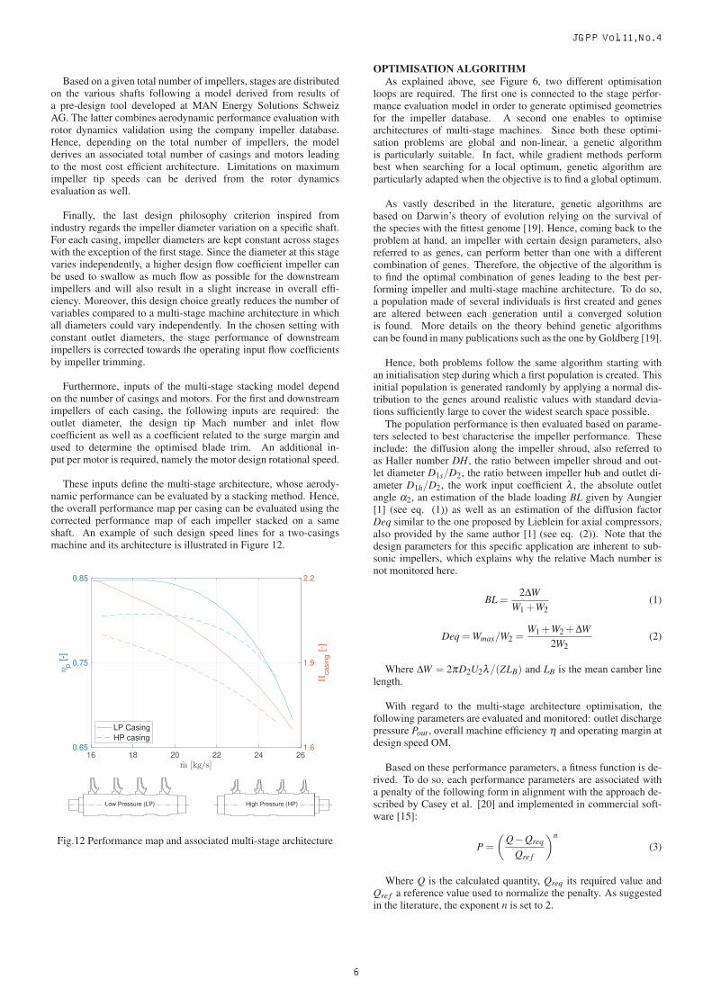
These inputs define the multi-stage architecture, whose aerody-namic performance can be evaluated by a stacking method. Hence,the overall performance map per casing can be evaluated using thecorrected performance map of each impeller stacked on a sameshaft. An example of such design speed lines for a two-casingsmachine and its architecture is illustrated in Figure 12.
16 18 20 22 24 260.65
0.75
0.85
p [-
]
1.6
1.9
2.2
casi
ng [-
]
LP CasingHP casing
Low Pressure (LP) High Pressure (HP)
Fig.12 Performance map and associated multi-stage architecture
OPTIMISATION ALGORITHMAs explained above, see Figure 6, two different optimisation
loops are required. The first one is connected to the stage perfor-mance evaluation model in order to generate optimised geometriesfor the impeller database. A second one enables to optimisearchitectures of multi-stage machines. Since both these optimi-sation problems are global and non-linear, a genetic algorithmis particularly suitable. In fact, while gradient methods performbest when searching for a local optimum, genetic algorithm areparticularly adapted when the objective is to find a global optimum.
As vastly described in the literature, genetic algorithms arebased on Darwin’s theory of evolution relying on the survival ofthe species with the fittest genome [19]. Hence, coming back to theproblem at hand, an impeller with certain design parameters, alsoreferred to as genes, can perform better than one with a differentcombination of genes. Therefore, the objective of the algorithm isto find the optimal combination of genes leading to the best per-forming impeller and multi-stage machine architecture. To do so,a population made of several individuals is first created and genesare altered between each generation until a converged solutionis found. More details on the theory behind genetic algorithmscan be found in many publications such as the one by Goldberg [19].
Hence, both problems follow the same algorithm starting withan initialisation step during which a first population is created. Thisinitial population is generated randomly by applying a normal dis-tribution to the genes around realistic values with standard devia-tions sufficiently large to cover the widest search space possible.
The population performance is then evaluated based on parame-ters selected to best characterise the impeller performance. Theseinclude: the diffusion along the impeller shroud, also referred toas Haller number DH, the ratio between impeller shroud and out-let diameter D1s/D2, the ratio between impeller hub and outlet di-ameter D1h/D2, the work input coefficient λ , the absolute outletangle α2, an estimation of the blade loading BL given by Aungier[1] (see eq. (1)) as well as an estimation of the diffusion factorDeq similar to the one proposed by Lieblein for axial compressors,also provided by the same author [1] (see eq. (2)). Note that thedesign parameters for this specific application are inherent to sub-sonic impellers, which explains why the relative Mach number isnot monitored here.
BL =2ΔW
W1 +W2(1)
Deq =Wmax/W2 =W1 +W2 +ΔW
2W2(2)
Where ΔW = 2πD2U2λ/(ZLB) and LB is the mean camber linelength.
With regard to the multi-stage architecture optimisation, thefollowing parameters are evaluated and monitored: outlet dischargepressure Pout , overall machine efficiency η and operating margin atdesign speed OM.
Based on these performance parameters, a fitness function is de-rived. To do so, each performance parameters are associated witha penalty of the following form in alignment with the approach de-scribed by Casey et al. [20] and implemented in commercial soft-ware [15]:
P =
(Q−Qreq
Qre f
)n(3)
Where Q is the calculated quantity, Qreq its required value andQre f a reference value used to normalize the penalty. As suggestedin the literature, the exponent n is set to 2.
JGPP Vol. 11, No. 4
6

Alternative expressions are used depending on the objectives as-sociated with each performance parameter. These could simply beto maximise/minimise in absolute (referred to as type 1) or until acertain value (referred to as type 2) the parameter value or to main-tain it within a certain target range (referred to as type 3). For bothoptimisation problems, all performance parameters mentioned pre-viously are given in Table 2 together with penalty function types(i.e. 1, 2 or 3), objective values and reasons for choosing these pa-rameters.
Table 2 Performance parameters and associated penalty functions
Param. Type Value Reason
Impeller optimisation
DH 2 ≥ 0.70 Minimise flow separation
D1s/D2 3 ≥ 0.40 Minimise losses≤ 0.75
D1h/D2 3 ≥ 0.35 Shaft stiffness≤ 0.50
λ 1 Maximise Maximise pressure rise
α2 3 ≥ α2ob j −1◦ Minimise losses
≤ α2ob j +1◦ through diffuser
Deq 2 ≤ 1.70 Reasonable surge margin
BL 2 ≤ 0.90 Reasonable blade loading
Z 1 Minimise Minimise polar inertia
Multi-stage architecture optimisation
η 1 Maximise Maximise efficiency
Pout 3 ≥ Poutob j Required pressure rise
≤ Poutob j +1 bar
OM 2 ≥ 0.35 Required minimum OM
The weighted sum of all penalties is then calculated and thefitness function representing the overall penalty is subsequentlyminimised.
Following this evaluation process, a selection is made withinthe population to identify the parents of the next generation. Acrossover and mutation process are thus required to construct thisnew generation. On the one hand, during the crossover step, alsocalled reproduction, genes are exchanged between individuals.On the other hand, during the mutation process, specific genesof individuals can mutate and vary within a certain range. Foreach of these processes, different methods have been implementedand tested. These are listed below for completeness. Moreinformation on these models as well as additional ones can easilybe found in the literature (e.g. Goldberg [19] or Muhlenbein andSchlierkamp-Voosen [21]).
Selection: Uniform, truncation, tournament and roulette wheelCrossover: Single points, two points, uniform and half uniformdiscrete, extended intermediate recombination (EIR), extended linerecombination (ELR)Mutation: Power law uniform distributed and normal distributed
The different selection, crossover and mutation methods havebeen implemented and tested to study their effect on the conver-gence rate and the capacity of finding a global optimum amongmany local optima. Methods leading to what is commonly referredto as a Breeder Genetic Algorithm (BGA) [21] are then appliedto both optimisation problems. Hence, a truncation selection, anormal distributed mutation and an extended line recombination areused. Alternative algorithms such as Adaptive Genetic Algorithm(AGA) have also been analysed but proved to be less effective forsuch optimisation problems.
In addition, a scaling of the fitness function is implemented to en-sure that the algorithm does not converge too rapidly towards a lo-cal optimum. This could be the case when individuals, which seeminitially weak, are disregarded although they could have provided
genes leading to an optimised solution at a later stage. Hence, thisscaling of the fitness function enables to maintain a diversity amongthe pool of candidates. The raw fitness function can be scaled fol-lowing different distributions such as linear, power law, exponentlaw or sigma. After having tested these different methods, the linearscaling appeared be the most effective for the impeller optimisationand the exponent law for the multistage architecture optimisation.An elite selection was also implemented to ensure that the best in-dividual found in previous iterations is kept from one generation toanother.
Finally, a hill climbing process is initiated as soon as either nomore reduction of the fitness function is observed from itecheck it-erations on or after a certain number of iterations. This processenables to realise the latest incremental improvements by focusingon the near vicinity of the last result obtained and thus to reach theglobal optimum of the fitness function. This algorithm and the dif-ferent processes mentioned above are summarised in Figure 13.
Initialisation
Evaluation
Fitness scaling
Selection: Truncation + elite
Crossover: Extended Line
Recombinaition (ELR)
Mutation: Normally distributed
Hill climbing
Final solution
yes
no
ite = itemax ite = ite+1
yes no
ite = 1
F(ite)-F(ite-itecheck) = 0
Fig.13 Genetic algorithm
RESULTSImpeller database generation
To generate an impeller database covering the needs of all gasmixtures, impellers have been designed with following design pa-rameters: design flow coefficients between 0.01 and 0.11 with 0.005steps and for impeller tip Mach numbers between 0.1 and 0.7 with0.05 steps. A meridional view of the results obtained with this op-timisation is given in Figure 14 for a design tip Mach number of0.4. The database generated enables to select the optimum impellerdesign enhancing the performance of the multi-stage architecture.
Fig.14 Impeller geometry variation with respect to the design inletflow coefficient
Figures 15 provides an overview of the performance and geomet-rical parameters of impellers constituting the database for a designtip Mach numbers of 0.4. Hence, the stage polytropic efficiency
JGPP Vol. 11, No. 4
7

obtained from Rusch and Casey’s expression [4] for a low tip Machnumber is displayed together with the predicted polytropic pressurecoefficients. When looking at the literature, these distributionsof performance parameters are in good agreement with the onesprovided by Aungier [1].
Moreover, it can already be deduced that a trade-off between ma-chine efficiency and total number of stages exists. In fact, on theone hand, for a low amount of stages satisfying the total pressureratio requirement, impeller diameters will have to be maintained ashigh as possible, constraining the inlet flow coefficient to decreaserapidly between stages together with the efficiency per stage. Onthe other hand, for a higher amount of stages, the impeller diame-ters can be reduced more severely from one casing to another. Thisresults into impellers with design inlet flow coefficients maintainedat a higher average level, thus leading to higher overall machineefficiencies.
0 0.04 0.08 0.12
t1d [-]
0.4
0.5
0.6
0.7
0.8
0.9
p [-],
p [-]
p
p
0 0.04 0.08 0.12
t1d [-]
-90
-70
-50
-30
-10
' 2 [°],
' 1s [°
], ' 1h
[°]
'2
'1s
'1h
Fig.15 Performance (on the left) and geometrical (on the right) pa-rameters of impellers within the database for MU2d = 0.4
Since all the designs of interest are for tip Mach numbers below0.8, the stage performance does not vary with this design parameterand only depends on the inlet flow coefficient. Moreover, design-ing impellers for these high speed of sound gases also explains thecomparatively low shroud inlet blade angle β ′
1s in comparison to themore conventional air impellers. In fact, as explained by Rusch andCasey [4], by assuming a zero incidence at the impeller shroud, anoptimal blade angle can be determined resulting in a minimum inletrelative Mach number Mw1 and thus, lower losses explained by alower diffusion along the impeller shroud.
To do so, an expression for a modified mass flow function result-ing in equation (4) is derived and written with respect to the impellerinlet relative Mach number and shroud flow angle:
4φt1M3U2
kπ=
M3w1s sin2 β1s cos β1s[
1+ γ−12 M2
w1s cos2 β1s
]1/(γ−1)+3/2(4)
This function is plotted in Figure 5 of Rusch and Casey [4] fordifferent inlet relative Mach numbers and shows that for each mod-ified flow coefficient a minimum inlet relative Mach number can bedetermined with an optimal inlet fluid angle. Moreover, for low in-let relative Mach numbers such as for light gases application, thesecond term of equation (4) can be reduced to tan2(β1s). Hence, inthis specific case, the function maximum corresponding to the min-imum inlet relative Mach number is reached at β1s = 54.74◦. Thisresult can be observed in Figure 16, where the impeller shroud inletsolid angle is displayed for different tip Mach numbers. Passed thedesign cases with the highest gas speed of sound, the absolute valueof this angle increases mainly with the tip Mach number but the in-fluence of the design inlet flow coefficient also grows in magnitude.
0 0.02 0.04 0.06 0.08 0.10 0.12
t1d [-]
-59.0
-58.5
-58.0
-57.5
-57.0
-56.5
-56.0
-55.5
-55.0
-54.5
' 1s [°
]
MU
2d = 0.1
MU
2d = 0.2
MU
2d = 0.3
MU
2d = 0.4
MU
2d = 0.5
MU
2d = 0.6
MU
2d = 0.7
Fig.16 Influence of impeller design tip Mach number and inlet flowcoefficient on impeller inlet shroud angle
Moreover, since the inlet shape factor increases with the designinlet flow coefficient, the hub diameter is also reduced as it can beseen in Figure 14. This also results in short and large diametershaft for the low flow coefficient impellers and thinner and longershaft for the high flow coefficient impellers. This observation alsoimplies that the absolute hub blade angle decreases for higher flowcoefficients in order to compensate for the lower rotational speedwhile maintaining a reasonable flow incidence (see Figure 15).
Finally, the absolute outlet blade angle also has a tendency to de-crease as the inlet flow coefficient increases. In fact, by increasingthe design inlet flow coefficient at a constant impeller tip speed, theoutlet blade angle has to be reduced if the objective is to maintaina high work input coefficient maximising the pressure rise per stage.
Multi-stage architecture at a fixed gas composition (xHe = 0.5)Results of the multi-stage architecture optimisation are first pre-
sented for a constant operating gas mixture with a helium mole frac-tion of 0.5 and then for the whole gas mixture range. Starting with aconstant operating gas mixture, the convergence of the multi-stagearchitecture optimisation is illustrated below. This calculation aimsat maximising both the efficiency and the operating margin. More-over, penalties associated to these parameters are also provided. Asexpected, results show that the efficiency and operating margin pro-gressively increase with iterations while their associated penaltiesdecrease. Additionally, the penalty associated with the dischargepressure enables to keep the latter inside the desired range.
00.5
11.5
2
PP
out [-
]
3234363840
Pou
t [bar
]
PenaltyP
out
0
2
4
6
Pp [-
]
0.75
0.8
0.85
0.9
p [-]Penalty
0 200 400 600 800iterations [-]
10
20
30
PO
M [-
]
0.3
0.4
0.5
OM
[-]Penalty
OM
Fig.17 Convergence of the multi-stage architecture optimisation
JGPP Vol. 11, No. 4
8

Following the same optimisation calculation as shown in Figure17, the population performance evolves through iterations until ithits a Pareto front trading efficiency for range (see Figure 18).
0.6 0.7 0.8 0.9
p [-]
0.1
0.2
0.3
0.4
0.5
0.6
0.7
OM
[-]
1st to 10th generation
11th to 50th generation
50th to 100th generation
101th to 1000th generationPareto front
0.85 0.88
p [-]
0.35
0.40
0.45
0.50
OM
[-]
Fig.18 Pareto front between efficiency and operating margin
In order to understand the factors influencing the previously men-tioned performance parameters, an impact analysis of the modelinputs is conducted using optiSLang [22]. This tool assesses themodel quality through the Coefficient of Progonosis (CoP), calcu-lated from the squared error obtained with a yet unused data set. ACoP value is given for the complete model as well as for each indi-vidual input computed with their sensitivity indices and indicatingtheir respective impacts. Since only the overall machine efficiencycould be predicted in a short time using a polynomial model leadingto reasonable accuracy (i.e. above 90% of CoP), only the effect ofthe input parameters on the latter is analysed. A comparable accu-racy could be obtained for the operating margin but required timeconsuming models. The analysis was conducted for architecturesdesigned at seven different gas mixtures between pure helium andpure neon each time with a sample size greater than 3’000. Figure19 displays the average CoP of the input parameters for a represen-tative case obtained at xHe = 0.5. The same order of importancebetween input parameters is observed for other gas mixtures.
D2
h2 t1d
MU
2d
Input parameter
0
20
40
60
80
100
Coe
ffici
ent o
f Pro
gnos
is (
CoP
) [%
]
Fig.19 Impact of input parameters on overall machine efficiency
These results are inherent to the approach followed in themulti-stage optimisation model as well as to the strong relationbetween inlet flow coefficient and stage efficiency. In fact, in orderto select impellers with suitable design inlet flow coefficient and tipMach number from the database, a distribution of these parametersthrough the machine is first estimated using the impeller diametersand shaft rotational speed. Changes to the selected design inlet flow
coefficient and tip Mach number with respect to this inital guesscan then be applied for each impeller using two of the model inputparameters, namely Δφt1d and ΔMU2d . Moreover, since the inlet
flow coefficient evolves with D32 but is only proportional to 1/Ω
a step change in impeller diameter has a comparatively strongerimpact on the flow coefficient than a change in rotational speed.However, for heavier gas application, a more pronounced impactof the rotational speed would be anticipated due to the tip Machnumber effect on the stage efficiency.
The second parameters influencing strongly the efficiency is theone defining the reduction of impeller outlet width due to bladetrimming. Its effect on the stage performance and consequentlyon the overall machine efficiency can be easily explained by theperformance correction illustrated in Figure 10.
Finally, the effect of a variation of design inlet flow coefficientand tip Mach number on the machine overall efficiency resultsmainly from an off-design drop in stage efficiency. In addition,the variation of design inlet flow coefficient also impacts the stageefficiency at design point. This is however not the case for the tipMach number since the latter is too low for this specific applicationto have any effect on the stage performance at design point.
As previously explained, these first optimisations aim at max-imising both the efficiency and the operating margin. However,since the operating margin is not critical for the application understudy, only the efficiency is now maximised and a minimum oper-ating margin is defined (Table 2). The impact of this constraint onthe operating margin and of the number of stages on efficiency isshown in Figure 20.
9 11 13 15 17
Number of stages [-]
0.80
0.85
0.90
p [-]
0.3
0.4
0.5
OM
[-]
p
OMMaximum OMRequire minimum OM
Fig.20 Effect of the operating margin constraint and the number ofstages on overall efficiency
As already illustrated by the Pareto front, removing the operatingmargin maximisation constraint leaves some room for improvementof the efficiency. Hence, regardless of the number of stages, theoverall machine efficiency at a maximised operating margin isalways lower than the one at an operating margin set above aspecific threshold. Moreover, for both optimisation objectives, itcan be observed that adding more stages contributes to increasingthe overall machine efficiency but only up to a certain value. Passthis limit, adding additional stages penalises efficiency but can stillimprove the operating margin further.
The number of available impeller families also impacts the ma-chine performance and architecture. Figure 21 displays the over-all machine efficiency evolution as the number of impeller familiesused in architectures increases. Results are given for architecturesproviding the required discharge pressure, i.e. machines constitutedof 9 to 13 stages.
JGPP Vol. 11, No. 4
9

2 3 4 5 6 7
Number of impeller family used [-]
0.78
0.80
0.82
0.84
0.86
0.88
p [-]
9 Stages10 Stages11 Stages12 Stages13 StagesMinimum OM not achievedMinimum OM achieved
Fig.21 Effect of the impeller family variety on overall efficiency
Firstly, it can be observed that a too small number of impellerfamilies does not guarantee the minimum required operatingmargin. Once the first configuration respecting the constraint onthe operating margin is identified, the overall machine efficiencyprogressively increases with the number of impeller families.Hence, instead of designing the machine with a limited number ofimpeller families and thus relying on blade trimming to obtain theright flow coefficient, increasing the number of available familiesenables to provide each stage with an impeller designed as closeas possible to the machine operation requirement. This improvedefficiency reaches its limit above a certain number of families,stays roughly constant and can even decrease if a too diverse set ofimpellers is used. This decrease in efficiency after a certain numberof impeller families is strongly correlated with the discretisation ofthe design inlet flow coefficient and tip Mach number inside thedatabase. In fact, by forcing the multi-stage architecture to includea high amount of different impeller families in comparison with theimpeller diversity of the database, suboptimal impellers are placedin the architecture. As a result, from an efficiency perspective, itis recommended to define an optimal number of impeller fami-lies above which no additional gain in overall efficiency is observed.
When one compares different architectures with different num-ber of stages at a constant number of impeller families, results sim-ilar to the ones presented in Figure 20 can be observed. In fact,the overall machine efficiency improves as the number of stages in-creases. However, the incremental efficiency decreases until addingmore stages does not contribute anymore to the overall machine ef-ficiency and even leads to its deterioration. This could be replicatedfor other gas mixtures and therefore, an optimised multi-stage ar-chitecture can also be obtained in order to either:
• minimise the number of required stages, risking to compro-mise the overall efficiency, or
• maximise the overall efficiency, risking to require several ad-ditional stages.
Multi-stage architecture: from pure helium to pure neonThe following section focuses on the results obtained for the
whole gas mixture range, i.e. from pure helium to pure neon.Firstly, as already mentioned, multi-stage architectures can beoptimised to either minimise the number of required stages ormaximise their overall efficiency while maintaining a reasonableoperating margin. Figure 22 highlights the difference in numberof stages between these two optimisation objectives for the gasmixtures of interest. The first observable trend is that, whateverthe objective, the number of required stages increases with highercontent of helium following a quadratic distribution with a sharp
increase in the required number of stages above a 0.5 helium molefraction. This observation was already foreseen in the pressureratio per stage estimation given for different gas mixtures in Figure4. This result also explains the current difficulty of turbomachinemanufacturers to design a sealed, compact and economicallyaffordable machine for pure helium due to the high number ofrequired stages associated with this application.
Another observation, which can be inferred from Figure 22, isthat the architecture with the highest overall efficiency requires thehighest number of stages and significantly more so at high con-tent of helium compared to architectures with minimum number ofstages. Therefore, at pure helium a significant number of stageshas to be added, in comparison to the pure neon case, to reach thehighest efficiencies. Designing a multi-stage turbocompressor re-specting the target discharge pressure is already costly and financialchallenges are accentuated for heavier operating gases if the objec-tive is to design a highly efficient machine.
0 0.2 0.4 0.6 0.8 1.0
xHe [-]
10
15
20
25
30
35
40
Num
ber
of s
tage
s [-
]
Minimum number of stagesMaximum efficiencyTrends
Fig.22 Required number of stages with respect to the helium molefraction
To explain the variations in number of stages and efficienciesbetween different gas mixtures, it is worth looking at the design im-peller inlet flow coefficients and tip Mach numbers chosen for thedifferent architectures. Figure 23 shows for several gas mixtures theaverage value of the previously mentioned parameters per architec-ture when the required number of stages is minimised.
0.035 0.045 0.055 0.0650.10
0.15
0.20
0.25
0.30
0.35
0.40
0.45xHe = 0xHe = 0.2xHe = 0.4xHe = 0.5xHe = 0.6xHe = 0.8xHe = 1
Fig.23 Average φt1d and MU2d in multi-stage machine architecturefor different operating gas compositions
JGPP Vol. 11, No. 4
10

As expected, the design impeller tip Mach numbers chosen forthe architectures decreases as the gas becomes lighter and the gasspeed of sound increases. Moreover, the inlet flow coefficients alsodecrease as the mole fraction of helium increases. This is causedby a lower operating mass flow rate for pure helium than for pureneon operation and cannot be compensated by the impeller diameteror rotational speed due to the objective of maximising the pressurerise per stage.
Another particularly important aspect to consider is the effectof impeller database limitations on the performance of the over-all machine. The results discussed above have been obtained us-ing a relatively diversified impeller database with a wide range ofdesign tip Mach numbers and inlet flow coefficients. Hence, Fig-ure 24 compares the minimum number of required stages obtainedusing the diversified impeller database with the ones obtained us-ing two databases containing impellers designed for respectively apure neon (MU2d = 0.4) and a heavier hypothetic monoamotic gas(MU2d = 0.7) application. Moreover, both databases include six im-pellers designed for input flow coefficients between 0.02 and 0.09.
0 0.2 0.4 0.5 0.6 0.8 1
xHe [-]
0
1
2
3
4
5
6
Add
ition
al n
umbe
r of
sta
ges
[-]
MU
2d = 0.4
MU
2d = 0.7
Fig.24 Effect of available impellers on the number of stages
As illustrated by Figure 24, an impeller database designed witha tip Mach number tailored to a gas molecular weight deviatinggreatly from the operating gas significantly impacts the multi-stagearchitecture. For instance, selecting only impellers with tip Machnumbers characteristic of pure neon (MU2d = 0.4) to be part of anew database leads to an architecture with three additional stageswhen the machine is operated with pure helium. This effectis emphasised when the database is optimised for even heaviergases. This can be explained by the fact that the two databasesare designed at constant tip Mach numbers but the multi-stagemachines are stacked with impellers operating within a rangearound the average tip Mach numbers given in Figure 23. Thisrestricted flexibility in the available MU2d as well as φt1d alsocontributes to needing additional stages. Figure 24 thus highlightsthe need of using impellers with suitable design tip Mach numberstailored to the operating gas, especially when the objective is toreduce the number of required stages.
The last effect of interest comes from potential technological im-provements, which can be anticipated in the near future. Amongthese, the access to lighter materials or the development of mo-tors both with increased maximum rotational speeds and maintainedhigh input power are particularly promising. These technologicaladvancements would enable to reach higher impeller tip speeds.Higher maximum rotational speeds and increased maximum allow-able impeller tip speeds constrained by the rotor dynamics result invariations of the multi-stage architecture as illustrated in Figure 25.
0 0.2 0.4 0.5 0.6 0.8 1.0
xHe [-]
0
1
2
3
4
5
6
7
8
Num
ber
of s
tage
s sp
ared
[-]
(Ref
eren
ce
max
= 1
1500
RP
M) max
= 12500 RPM
max = 13500 RPM
max = 14500 RPM
Fig.25 Effect of the maximum motor rotational speed on the numberof stages
It can be noted that this impact appears for gases with a heliummole fraction above 0.5. Beyond this threshold, increasing the max-imum rotational speed enables to reduce the required number ofstages. Consequently, this effect becomes more pronounced as thethe gas density is reduced. All in all, the highest the maximum ro-tational speed unlocked by technological progress, the strongest thepotential improvements in multi-stage architecture compactness.
CONCLUSIONSThis paper takes the industrial perspective of multi-stage turbo-
compressor design and applies it to a light gas application (i.e. amixture of helium and neon) resulting from CERN’s specificationsfor the new cryogenic cycle of their Future Circular Collider.Hence, a stage performance prediction and a stage stacking modelare coupled to a same optimisation algorithm in order to build animpeller database and design a multi-stage machine at a specificgas mixture. A model predicting the performance correction of ascaled or trimmed impeller is also implemented. Design boundaryconditions observed in industry and resulting from design philoso-phies, impeller material or manufacturing techniques available aswell as rotor dynamics limitations are taken into account.
The stage performance and geometry of impellers constitutingthe database is first presented and compared to the literature fordifferent design flow coefficients and tip Mach numbers. Results ofthe multi-stage design optimisation are then described for a specificgas mixture together with the Pareto front leveraging efficiency forrange. The influence of the different parameters defining the archi-tecture on the overall machine efficiency is also analysed. Then,results show that an optimal number of stages for either the mostcompact or efficient machine can be determined. Moreover, for agiven gas mixture, the diversity of impeller family in the machinearchitecture also contributes to its overall performance. Thus, aminimum number of family is required to achieve the minimumdesired operating range. Imposing a stronger diversity leads to anincrease in overall machine performance until an excess in diversitybecomes detrimental. Results are then provided for the whole rangeof gas mixture, highlighting how the number of required stagesincreases exponentially with helium content. As the gas becomeslighter, the average machine flow coefficient and tip Mach numberalso decrease. The available impeller in the database as well as theforeseen technological improvements greatly influence the finalmulti-stage architecture. Relying on a compressor database witha limited number of design flow coefficients and optimised forheavier gases than the application requires leads to less compactarchitectures in comparison to a machine with fully tailored-designstages. Finally, enhancing the motor performance by increasing
JGPP Vol. 11, No. 4
11

its maximum rotational speed together with its rated power alsocontributes to reducing the required number of stages especially forhigh helium content.
In future work, several improvements of the models would helpmake the latter suited for a wider range of applications. The multi-stage design model would gain in additional degrees of freedomby implementing different ways of impeller trimming together withtheir effect on the stage performance. Moreover, it would be worthextending the models to heavier gases such as air or even heavy gasmixtures such as the ones encountered in the oil and gas industry. Aperformance correction capturing the change in specific heat ratiowould also come fine tune the model prediction. This would enableto further validate the results with existing multi-stage machines.An experimental validation of the off-design model using an indus-trial compressor stage with vaned diffuser and designed for lightgases is also scheduled for the near future. The coefficients respon-sible for the surge and choke margins prediction could therefore becalibrated for this specific application instead of being restricted tothe literature-recommended values.Furthermore, one limitation of the current model is the inherent linkwith the baseline machine used. Even if MAN Energy Solutions ex-perience with the HOFIMTM architecture enables to provide designboundaries such as limitations for the required number of stages andmaximum impeller tip speeds, it also restricts the application to thisspecific machine. This limitation could be lifted by implementinga model directly connecting shaft and impeller geometry as well asrotational speed to the allowable number of stages per shaft. More-over, by doing so, the impeller database would be comprised of ge-ometries optimised not only for aerodynamic performance but alsofor rotor dynamics restrictions. Finally, with such a model takinginto account the effect of impeller material on the rotor dynamics,a more accurate estimation of the gain coming from technologicalimprovements would be possible.
ACKNOWLEDGMENTSThe valuable technical discussions and email exchanges with
Chirstoph Andris and Dr. Bob Mischo from MAN Energy Solu-tions are gratefully acknowledged. Moreover, the first author wouldlike to thank MAN Energy Solutions for having provided in houseresources and tools as well as valuables informations on their prod-ucts and engineering experience. Finally, the author would also liketo thank the ITSM for providing the computing tools and the MarieSkodolwska-Curie Action (MSCA) for its financial support, whichmade this work possible.
EASITrain - European Advanced Superconductivity In-novation and Training. This Marie Sklodowska-CurieAction (MSCA) Innovative Training Networks (ITN)
has received funding from the European Union’s H2020 FrameworkProgramme under Grant Agreement no. 764879
References[1] Aungier, R. H., 2000, “Centrifugal Compressors - A Strategy
for Aerodynamic Design and Analysis“, ASME, New York.
[2] Ludtke, K. H., 2004, “Process Centrifugal Compressors“,Springer, Berlin.
[3] Dixon, S. L., 2005, “Fluid mechanics and thermodynamicsof turbomachinery, 5th edition“, Butterworth-Heinemann, Ox-ford.
[4] Rusch, D. and Casey, M., 2013, “The Design Space Boundariesfor High Flow Capacity Centrifugal Compressors”, Journal ofTurbomachinery, Vol. 135.
[5] Casey, M. V., and Schlegel, M., 2010, “Estimation of thePerformance of Turbocharger Compressors at Extremely LowPressure Ratios,” Proceedings of the Institution of MechanicalEngineers, Part A: Journal of Power and Energy, Vol. 224, pp.239–250.
[6] Dalbert, P., Casey, M.V., and Schurter, E., 1988, “Develop-ment, testing and performance prediction of radial stages formulti-stage industrial Compressors”, Journal of Turbomachin-ery, Vol. 110, pp. 283-292.
[7] Dalbert, P., Ribi, B. and Casey, M. V., 1999, “Radial compres-sor design for industrial compressors“, Proceedings of the Insti-tution of Mechanical Engineers, Part C: Journal of MechanicalEngineering Science, Vol. 213, pp. 71-83.
[8] Al-Busaidi, W., and Pilidis, P., 2016 “A new method for reli-able performance prediction of multi-stage industrial centrifu-gal compressors based on stage stacking technique: Part I – ex-isting models evaluation“, Applied Thermal Engineering, Vol.98, pp. 10-28.
[9] Al-Busaidi, W., and Pilidis, P., 2015, “A new method for re-liable performance prediction of multi-stage industrial cen-trifugal compressors based on stage stacking technique: PartII–New integrated model verification“, Applied Thermal Engi-neering, Vol. 90, pp. 927-936.
[10] Romei, A., Maffulli, R., Sanchez, C. G., and Lavagnoli, S.,2017, “Design and Optimization of Multi-Stage CentrifugalCompressors With Uncertainty Quantification of Off DesignPerformance“, ASME Turbo Expo 2017.
[11] Wiesner, F. J., 1967, “A review of slip factors for centrifugalimpellers“, Journal of Engineering for Power, Vol. 89, pp. 558-566.
[12] Casey M.V., Robinson C.J., 2006, “A guide to turbochargercompressor characteristics”, Dieselmotoren- technik.
[13] Casey, M. and Robinson, C.J., 2013, “A Method to Estimatethe Performance Map of a Centrifugal Compressor Stage”,Journal of Turbomachinery, Vol. 135.
[14] Casey, M. and Rusch, D., 2014, “The matching of a vaneddiffuser with a radial compressor impeller and its effect on thestage performance. Journal of Turbomachinery“, Vol. 136.
[15] NUMECA International, 2009, ”FINE/Turbo v8. 7, user man-ual”, Brussels.
[16] Casey, M. V. and Robinson, C. J., 2011, “A unified correc-tion method for Reynolds number, size, and roughness effectson the performance of compressors“, Proceedings of the Insti-tution of Mechanical Engineers, Part A: Journal of Power andEnergy,Vol. 225, pp. 864–876.
[17] Strub, R. A., et al., 1987, “Influence of the Reynolds Numberon the Performance of Centrifugal Compressors”, ASME Jour-nal of Turbomachinery, Vol. 109, pp. 541-544.
[18] Casey, M.V., 1985, ”The effects of Reynolds number on theefficiency of centrifugal compressor stages”, Journal of Engi-neering for Gas Turbines and Power, Vol. 107, pp. 541-548.
[19] Goldberg, D.E., 1989, “A genetic Algorithms in Search, Opti-misation and Machine Learning“, Addison, Wesley.
[20] Casey, M.V., Gersbach, F., and Robinson, C.J, 2008, “Anew optimisation technique for radial compressor impellers”,ASME Turbo Expo 2008.
[21] Muhlenbein, H., and Schlierkamp-Voosen, D., 1993, ”Predic-tive models for the breeder genetic algorithm”, Evolutionarycomputation, Vol. 1, pp. 25-49.
[22] DYNARDO GmbH, 2012, “Methods for multi-disciplinaryoptimization and robustness analysis“, Weimar.
[23] Lemmon, E. W., Bell, I. H., Huber, M. L., and McLin-den, M. O., 2018, NIST Standard Reference Database 23:Reference Fluid Thermodynamic and Transport Properties-REFPROP, Version 10.0, National Institute of Standards andTechnology.
[24] TUV SUD NEL PPDS Software [Computer software]. Re-trieved from: http://www.tuvnel.com.
JGPP Vol. 11, No. 4
12