imo modu-89.pdf
DESCRIPTION
Modu Codes 89TRANSCRIPT

Schlumberge Sedco Forex
Engineering Department
IMPORTANT NOTICEThis document is obtained from :
- the IMO 1989 MODU code and its 1991 amendments,- the SOLAS 1992 consolidated from the 1974 edition (1978 protocol
and attachments included) with its 1994 amendments.It contains, under the PDF format, the complete 1989 IMO MODU code, itsrelated 1991 amendments, and extracts from SOLAS 1992 and its 1994amendments. Direct access to the relevant SOLAS regulations (extracts) areavailable when referred to in the IMO MODU code. PDF Tool/Find options andbookmarks allow easy search through the text. Tables of contents of therelevant SOLAS chapters are also shown…
All above IMO publications are protected by copyrights. Accordingly, no part ofthis consolidated document shall be reproduced in any form or by any meansfor any official purpose : any copy shall be ordered from the InternationalMaritime Organization, 4 Albert Embankment, London SE1 7SR - UnitedKingdom (sales number for English versions : 811 90.05.E for the MODU code,IMO-863E for its 1991 amendments, IMO-110E for the 1992 SOLAS and IMO-190E for its 1994 amendments) or from the nearest national standardisationagency or technical library. Several copies are available within the ENGMontrouge department and its central library.
However, as this document is a basic document for the Sedco Forex offshorefleet, its access through the Sedco Forex Montrouge Web server has beenmade available for reference purpose only, in very specific cases: this facility isreserved to ENG personnel, for internal use when no official copies areeasily available.A password is required to open these documents : any request shall bedirected to the ENG Quality Manager..
Notes :1- Basic documents are the genuine IMO hard copies. Accordingly, if you notice
any discrepancy or if you have any comment, please inform by E-mail theENG Quality Assurance Manager at address :
2-Refer also to the IMO 1979 MODU code and the comparison table between1979 and 1989 codes available at the same location.Note : The PDF Tool/Find options are not operational for these two documents.
UNAUTHORIZED USER, PLEASE LOG OUT IMMEDIATELY
The ENG Quality Manager15 January 1998


CODE FOR THECONSTRUCTION AND EQUIPMENT
OF MOBILE OFFSHOREDRILLING UNITS, 1989
(1989 MODU CODE)

2
First published in 1980by the INTERNATIONAL MARITIME ORGANIZATION
4 Albert Embankment, London SE1 7SR
Revised edition 1990
Printed by Ashford Press Ltd., England
ISBN 92-801-1258-9Copyright © IMO 1990
IMO PUBLICATION
Sales number: 811 90.05.E
All rights reserved.No part of this publication may, for sales purposes,
be reproduced, stored in a retrieval system or transmittedin any form or by any means, electronic, electrostatic,
magnetic tape, mechanical, photocopying or otherwise,without the prior permission in writing from the
International Maritime Organization.

3
CODE FOR THE CONSTRUCTION AND EQUIPMENT OFMOBILE OFFSHORE DRILLING UNITS, 1989
(Resolution A.649(16) adopted on 19 October 1989 by theIMO Assembly at its sixteenth session)
THE ASSEMBLY,
RECALLING Article 15(j) of the Convention on the International Maritime Organizationconcerning the functions of the Assembly in relation to regulations and guidelines concerning maritimesafety,
NOTING that mobile offshore drilling units continue to be moved and operated internationally,
RECOGNIZING that the design criteria for such units are often quite different from those ofconventional ships and that, by virtue of this, the application of international conventions, such as theInternational Convention for the Safety of Life at Sea, 1974, as amended, and the InternationalConvention on Load Lines, 1966, as amended, is inappropriate in respect of mobile offshore drillingunits,
RECALLING that when the Code for the Construction and Equipment of Offshore Drilling Units(MODU Code) was adopted in 1979 by resolution A.414(XI) it was recognized that the designtechnology of mobile offshore drilling units was rapidly evolving and that new features of mobileoffshore drilling units would be introduced to improve technical and safety standards,
RECALLING ALSO that the Maritime Safety Committee was authorized to amend the Code asnecessary after due consultations with the relevant organizations, as the Committee deemed necessary,
NOTING that since the 1979 edition of the MODU Code was adopted there have been a numberof tragic MODU casualties which have emphasized the need for a review of the international safetystandards developed by the Organization,
HAVING CONSIDERED the recommendation made by the Maritime Safety Committee at itsfifty-seventh session,
1 ADOPTS the Code for the Construction and Equipment of Mobile Offshore DrillingUnits, 1989 (1989 MODU Code), the text of which is set out in the Annex to this resolution, whichsupersedes the existing MODU Code adopted by Assembly resolution A.414(XI) for mobile offshoredrilling units whose keels are laid or which are at a similar stage of construction on or after 1 May1991;
2. INVITES all Governments concerned:
(a) to take appropriate steps to give effect to the Code;
(b) to consider the Code as an equivalent, for purposes of application to mobile offshoredrilling units, to the technical requirements of the above-mentioned Conventions;

4
(c) to inform IMO of measures taken in this respect;.
3. AUTHORIZES the Maritime Safety Committee to amend the 1989 MODU Code,when appropriate, taking into consideration the developing design and safety features afterdue consultation with appropriate organizations.
5
ANNEX
CODE FOR THE CONSTRUCTION AND EQUIPMENT OFMOBILE OFFSHORE DRILLING UNITS, 1989
CONTENTS
Page
Preamble 9
Chapter 1 - GeneralSection 1 - Purpose 9Section 2 - Application 9Section 3 - Definitions 10Section 4 - Exemptions 14Section 5 - Equivalents 14Section 6 - Surveys and certification 14Section 7 - Control 16Section 8 - Casualties 16Section 9 - Review of the Code 17
Chapter 2 - Construction, strength and materialsSection 1 .........- General 17Section 2 .........- Design loads 17Section 3 .........- Structural analysis 18Section 4 .........- Special considerations for surface units 19Section 5 .........- Special considerations for self-elevating units 19Section 6 .........- Special considerations for column-stabilized units 20Section 7 .........- Fatigue analysis 21Section 8 .........- Materials 21Section 9 .........- Construction portfolio 21Section 10 .......- Welding 22Section 11 .......- Testing 22
Chapter 3 - Subdivision, stability and freeboardSection 1 - Inclining test 22Section 2 - Righting moment and heeling moment curves 22Section 3 - Intact stability criteria 25Section 4 - Subdivision and damage stability 26Section 5 - Extent of damage 28Section 6 - Watertight integrity 29Section 7 - Freeboard 30
Chapter 4 - Machinery installations for all types of unitsSection 1 - General 33Section 2 - Machinery requirements 34Section 3 - Steam boilers and boiler feed systems 35Section 4 - Steam pipe systems 35

6
Page
Section 5 - Machinery controls 35Section 6 - Air pressure systems 36Section 7 - Arrangements for oil fuel, lubricating oil and other
flammable oils 36Section 8 - Bilge pumping arrangements 36Section 9 - Ballast pumping arrangements on column-stabilized
units 37Section 10 - Protection against flooding 39Section 11 - Anchoring arrangements for surface and column-
stabilized units 40Section 12 - Dynamic positioning systems 41
Chapter 5 - Electrical installations for all types of unitsSection 1 - General electrical requirements 41Section 2 - Main source of electrical power 41Section 3 - Emergency source of electrical power 42Section 4 - Starting arrangements for emergency generators 45Section 5 - Precautions against shock, fire and other hazards of
electrical origin 46Section 6 - Internal communication 48
Chapter 6 - Machinery and electrical installations in hazardousareas for all types of units
Section 1 - Zones 48Section 2 - Classification of hazardous areas 49Section 3 - Openings, access and ventilation conditions affecting
the extent of hazardous areas 50Section 4 - Ventilation of spaces 50Section 5 - Emergency conditions due to drilling operations 51Section 6 - Electrical installations in hazardous areas 51Section 7 - Machinery installations in hazardous areas 52
Chapter 7 - Machinery and electrical installations forself-propelled units
Section 1 - General 53Section 2 - Means of going astern 53Section 3 - Steam boilers and boiler feed systems 54Section 4 - Machinery controls 54Section 5 - Steering gear 55Section 6 - Electric and electrohydraulic steering gear 57Section 7 - Communication between the navigating bridge and
the engine-room 57Section 8 - Engineers' alarm 57Section 9 - Main source of electrical power 57Section 10 - Emergency source of electrical power 58

7
Page
Chapter 8 - Periodically unattended machinery spaces forall types of units
Section 1 - General 58Section 2 - Application 59Section 3 - Fire safety 59Section 4 - Protection against flooding 61Section 5 - Bridge control of propulsion machinery 61Section 6 - Communication 62Section 7 - Alarm system 62Section 8 - Special requirements for machinery, boiler and
electrical installations 62Section 9 - Safety systems 63
Chapter 9 - Fire safetySection 1 - Structural fire protection 64Section 2 - Protection of accommodation spaces, service spaces
and control stations 67Section 3 - Means of escape 70Section 4 - Fire pumps, fire mains, hydrants and hoses 71Section 5 - Fire-extinguishing systems in machinery spaces and
in spaces containing fired processes 73Section 6 - Portable fire extinguishers in accommodation, service
and working spaces 74Section 7 - Fire detection and alarm system 74Section 8 - Gas detection and alarm system 74Section 9 - Firemen's outfits 74Section 10 - Arrangements in machinery and working spaces 75Section 11 - Provisions for helicopter facilities 75Section 12 - Storage of gas cylinders 76Section 13 - Miscellaneous items 77
Chapter 10 - Life-saving appliances and equipmentSection 1 - General 77Section 2 - Survival craft 78Section 3 -Survival craft muster and embarkation arrangements . 78Section 4 - Survival craft launching stations 79Section 5 - Stowage of survival craft 79Section 6 - Survival craft launching and recovery arrangements . .80Section 7 - Rescue boats 81Section 8 - Stowage of rescue boats 81Section 9 - Rescue boat embarkation, launching and recovery
arrangements 81Section 10 - Lifejackets 82Section 11 - Immersion suits 82Section 12 - Lifebuoys 82Section 13 - Radio life-saving appliances 83Section 14 - Distress flares 83

8
Page
Section 15 - Line-throwing appliances 83Section 16 - Emergency warnings 83Section 17 - Operating instructions 84Section 18 - Operational readiness, maintenance and inspections 84
Chapter 11- Radio communication installationsSection 1 - Application 85Section 2 - General 86Section 3 - Self-propelled units under way 86Section 4 - Units when towed, or self-propelled and accompanied
by escort ships 86Section 5 - Units stationary at the site or engaged in drilling
operations 86Section 6 - Helicopter communications 86Section 7 - Technical specifications for equipment 86Section 8 - Gas explosion danger 86Section 9 - Accommodation for radio personnel 87Section 10 - Survey of the radio station 87
Chapter 12 - Lifting devicesSection 1 - Cranes 87Section 2 - Personnel lifts 88Section 3 - Drilling derricks 88
Chapter 13 - Helicopter facilitiesSection 1 - General 89Section 2 - Construction 89Section 3 - Arrangements 89Section 4 - Visual aids 90
Chapter 14 - Operating requirementsSection 1 - Operating manuals 91Section 2 - Dangerous goods 93Section 3 - Pollution prevention 94Section 4 - Towing 94Section 5 - Transfer of material, equipment or personnel 94Section 6 - Diving systems 94Section 7 - Safety of navigation 95Section 8 - Emergency procedures 95Section 9 - Emergency instructions 96Section 10 - Training manuals 97Section 11 - Practice musters and drills 97Section 12 - On-board training and instructions 98Section 13 - Records 98
AppendixModel form of Mobile Offshore Drilling Unit Safety Certificate (1989) 99

9
PREAMBLE
1 This Code has been developed to provide an international standard for mobile off-shoredrilling units of new construction which will facilitate the international movement and operation ofthese units and ensure a level of safety for such units, and for personnel on board, equivalent to thatrequired by the International Convention for the Safety of Life at Sea, 1974, as amended, and theInternational Convention on Load Lines, 1966, for c6nventional ships engaged on internationalvoyages.
2 Throughout the development of the Code, it was recognized that it must be based upon sounddesign and engineering principles and experience gained from operating such units; it was furtherrecognized that design technology of mobile offshore drilling units Is not only a complex technologybut is rapidly evolving and that the Code should not remain static but be re-evaluated and revised asnecessary. To this end the Organization will periodically review the Code, taking into account bothexperience and future development.
3 Any existing unit which complies with the provisions of this Code should be consideredeligible for issuance of a certificate in accordance with this Code.
4 The Code is not intended to prohibit the use of an existing unit simply because its design,construction and equipment do not conform to the requirements of this Code. Many existing mobileoffshore drilling units have operated successfully and safely for extended periods of time and theiroperating history should be considered in evaluating their suitability to conduct internationaloperations.
5 The coastal State may permit any unit designed to a lower standard than that of the Code toengage in operations having taken account of the local environmental conditions. Any such unitshould, however, comply with safety requirements which in the opinion of the coastal State areadequate for the intended operation and ensure the overall safety of the unit and the personnel onboard.
6 The Code does not include requirements for the drilling of subsea wells or the procedures fortheir control. Such drilling operations are subject to control by the coastal State.
CHAPTER 1 - GENERAL
1.1 Purpose
The purpose of the Code for the Construction and Equipment of Mobile Offshore DrillingUnits, 1989, hereinafter referred to as the Code, is to recommend design criteria, constructionstandards and other safety measures for mobile offshore drilling units so as to minimize the risk tosuch units, to the personnel on board and to the environment.
1.2 Application
1.2.1 The Code applies to mobile offshore drilling units as defined in 1.3.1 to 1.3.4, the keels of whichare laid or which are at a similar stage of construction on or after 1 May 1991.
1.2.2 The coastal State may impose additional requirements regarding the operation of industrialsystems not dealt with by the Code.

10
1.3 Definitions
For the purpose of this Code, unless expressly provided otherwise, the terms used therein have themeanings defined in the following paragraphs.
1.3.1 Mobile offshore drilling unit or unit is a vessel capable of engaging in drilling operations forthe exploration for or exploitation of resources beneath the sea-bed such as liquid or gaseoushydrocarbons, sulphur or salt.
1.3.2 Surface unit is a unit with a ship- or barge-type displacement hull of single or multiple hullconstruction intended for operation in the floating condition.
1.3.3 Self-elevating unit is a unit with movable legs capable of raising its hull above the surface ofthe sea.
1.3.4 Column-stabilized unit is a unit with the main deck connected to the underwater hull or footingsby columns or caissons
1.3.5 Administration means the Government of the State whose flag the unit is entitled to fly.
1.3.6 Coastal State means the Government of the State exercising administrative control over thedrilling operations of the unit.
1.3.7 Organization means the International Maritime Organization (IMO).
1.3.8 Certificate means Mobile Offshore Drilling Unit Safety Certificate.
1.3.9 1974 SOLAS Convention means the International Convention for the Safety of Life at Sea,1974, as amended.
1.3.10 1966 Load Line Convention means the International Convention on Load Lines, 1966.
1.3.11 Mode of operation means a condition or manner in which a unit may operate or function whileon location or in transit. The modes of operation of a unit include the following:
l Operating conditions - conditions wherein a unit is on location for the purpose of conductingdrilling operations, and combined environmental and operational loading are within the appropriatedesign limits established for such operations. The unit may be either afloat or supported on the sea-bed, as applicable.
2 Severe storm conditions - conditions wherein a unit may be subjected to the most severeenvironmental loading for which the unit is designed. Drilling operations are assumed to have beendiscontinued due to the severity of the environmental loading. The unit may be either afloat orsupported on the sea-bed, as applicable.
.3 Transit conditions - conditions wherein a unit is moving from one geographical location toanother.
1.3.12 Freeboard is the distance measured vertically downwards amidships from the upper edge of thedeck line to the upper edge of the related load line.

11
1.3.13 Length (L) means 96% of the total length on a waterline at 85% of the least moulded depth (D)measured from the top of the keel, or the length from the foreside of the stem to the axis of the rudderstock on that waterline, if that be greater. In units designed with a rake of keel the waterline on whichthis length is measured should be parallel to the designed waterline.
1.3.14 Weathertight means that in any sea conditions water will not penetrate into the unit.
1.3.15 Watertight means the capability of preventing the passage of water through the structure in anydirection under a head of water for which the surrounding structure is designed.
1.3.16 Downflooding means any flooding of the interior of any part of the buoyant structure of a unitthrough openings which cannot be closed watertight or weathertight, as appropriate, in order to meetthe intact or damage stability criteria, or which are required for operational reasons to be left open.
1.3.17 Normal operational and habitable conditions means:.l conditions under which the unit as a whole, its machinery, services, means and aids ensuring
safe navigation when under way, safety when in the industrial mode, fire and flooding safety,internal and external communications and signals, means of escape and winches for rescueboats, as well as the means of ensuring the minimum comfortable conditions of habitability,are in working order and functioning normally; and
.2 drilling operations.
1.3.18 Gas-tight door is a solid, close-fitting door designed to resist the passage of gas under normalatmospheric conditions.
1.3.19 Main source of electrical power is a source intended to supply electrical power for all servicesnecessary for maintaining the unit in normal operational and habitable conditions.
1.3.20 Dead ship condition is the condition under which the main propulsion plant, boilers andauxiliaries are not in operation due to the absence of power.
1.3.21 Main switchboard is a switchboard directly supplied by the main source of electrical powerand intended to distribute electrical energy to the unit's services.
1.3.22 Emergency switchboard is a switchboard which, in the event of failure of the main system ofelectrical power supply, is directly supplied by the emergency source of electrical power and/or thetransitional source of emergency power and is intended to distribute electrical energy to the emergencyservices.
1.3.23 Emergency source of electrical power is a source of electrical power intended to supply thenecessary services in the event of failure of the main source of electrical power.
1.3.24 Main steering gear is the machinery, the steering gear power units, if any, and ancillaryequipment and the means of applying torque to the rudder stock, e.g. tiller or quadrant, necessary foreffecting movement of the rudder for the purpose of steering the unit under normal service conditions.

12
1.3.25 Auxiliary steering gear is the equipment which is provided for effecting movement of therudder for the purpose of steering the unit in the event of failure of the main steering gear.
1.3.26 Steering gear power unit means, in the case of:.l electric steering gear, an electric motor and its associated electrical equipment;
.2 electrohydraulic steering gear, an electric motor and its associated electrical equipment andconnected pump;
.3 other hydraulic gear, a driving engine and connected pump.
1.3.27 Maximum ahead service speed is the greatest speed which the unit is designed to maintain inservice at sea at its deepest seagoing draught.
1.3.28 Maximum astern speed is the speed which it is estimated the unit can attain at the designedmaximum astern power at its deepest seagoing draught.
1.3.29 Machinery spaces of category A are all spaces which contain internal combustion-typemachinery used either:
1 for main propulsion; or
.2 for other purposes where such machinery has in the aggregate a total power of not less than375 kW;
or which contain any oil-fired boiler or oil fuel unit; and trunks to such spaces.
1.3.30 Machinery spaces are all machinery spaces of category A and all other spaces containingpropelling machinery, boilers and other fired processes, oil fuel units, steam and internal combustionengines, generators and major electrical machinery, oil filling stations, refrigerating, stabilizing,ventilation and air-conditioning machinery and similar spaces; and trunks to such spaces.
1.3.31 Control stations are those spaces in which the unit's radio or main navigating equipment or theemergency source of power is located or where the fire recording or fire control equipment or thedynamical positioning control system is centralized or where a fire-extinguishing system servingvarious locations is situated. In the case of column-stabilized units a centralized ballast control stationis a "control station". However, for purposes of the application of chapter 9, the space where theemergency source of power is located is not considered as being a control station.
1.3.32 Hazardous areas are all those areas where, due to the possible presence of a flammableatmosphere arising from the drilling operations, the use without proper consideration of machinery orelectrical equipment may lead to fire hazard or explosion.
1.3.33 Enclosed spaces are spaces delineated by floors, bulkheads and/or decks which may havedoors or windows.
1.3.34 Semi-enclosed locations are locations where natural conditions of ventilation are notablydifferent from those on open decks due to the presence of structures such as roofs, windbreaks andbulkheads and which are so arranged that dispersion of gas may not occur.
1.3.35 Industrial machinery and components are the machinery and components which are used inconnection with the drilling operation.

13
1.3.36 Non-combustible material 1 means a material which neither burns nor gives off flammablevapours in sufficient quantity for self-ignition when heated to approximately 750°C, this beingdetermined to the satisfaction of the Administration by an established test procedure 2. Any othermaterial is a combustible material.
1.3.37 A standard fire test is a test as defined in regulation II-2/3.2 of the 1974 SOLAS Convention.
1.3.38 "A" class divisions are those divisions as defined in regulation II-2/3.3 of the 1974 SOLASConvention.
1.3.39 "B" class divisions are those divisions as defined in regulation II-2/3.4 of the 1974 SOLASConvention.
1.3.40 "C" class divisions are divisions constructed of approved non-combustible materials. Theyneed meet neither requirements relative to the passage of smoke and flame nor limitations relative tothe temperature rise.
1.3.41 Steel or equivalent material. Where the words "steel or equivalent material" occur, "equivalentmaterial" means any non-combustible material which, by itself or due to insulation provided, hasstructural and integrity properties equivalent to steel at the end of the applicable standard fire test (e.g.aluminium alloy with appropriate insulation).
1.3.42 Low flame spread means that the surface thus described will adequately restrict the spread offlame, this being determined to the satisfaction of the Administration by an established test procedure.
1.3.43 Continuous "B" class ceilings or linings are those "B" class ceilings or linings whichterminate only at an "A" or "B" class division.
1.3.44 Working spaces are those open or enclosed spaces containing equipment and processes,associated with drilling operations, which are not included in 1.3.30 or 1.3.32.
1.3.45 Accommodation spaces are those used for public spaces, corridors, lavatories, cabins, offices,hospitals, cinemas, games and hobbies rooms, pantries containing no cooking appliances and similarspaces. Public spaces are those portions of the accommodation which are used for halls, dining rooms,lounges and similar permanently enclosed spaces.
1.3.46 Service spaces are those used for galleys, pantries containing cooking appliances, lockers andstore-rooms, workshops other than those forming part of the machinery spaces, and similar spaces andtrunks to such spaces.
1.3.47 Fuel oil unit is the equipment used for the preparation of oil fuel for delivery to an oil-firedboiler, or equipment used for the preparation for delivery of heated oil to an internal combustionengine, and includes any oil pressure pumps, filters and heaters dealing with oil at a pressure morethan 0.18 N/mm².
1 If a material passes the test as specified in resolution A.270(VIII) it should be considered as "non-combustible" even if it consists of a mixtureof inorganic and organic substances. (Interpretation approved by the MSC at its forty-sixth session, SLS.14/Circ.17.)2 Reference is made to the Improved recommendation on test method for qualifying marine construction materials as non-combustible, adoptedby the Organization by resolution A.472(XII).

14
1.3.48 Survival craft are craft capable of removing persons from a unit to be abandoned and capableof sustaining persons until retrieval is completed.
1.3.49 Rescue boat is an easily manoeuvred power boat capable of rapid launching and adequate forquick recovery of a man overboard and towing a liferaft away from immediate danger.
1.3.50 Diving system is the plant and equipment necessary for the safe conduct of diving operationsfrom a mobile offshore drilling unit.
1.4 Exemptions
An Administration may exempt any unit which embodies features of a novel kind from any of theprovisions of the Code the application of which might impede research into the development of suchfeatures. Any such unit should, however, comply with safety requirements which, in the opinion ofthat Administration, are adequate for the service intended and are such as to ensure the overall safetyof the unit. The Administration which allows any such exemption should list such exemptions on theCertificate and communicate to the Organization the particulars, together with the reasons therefor, sothat the Organization may circulate the same to other Governments for the information of theirofficers.
1.5 Equivalents
1.5.1 Where the Code requires that a particular fitting, material, appliance, apparatus, item ofequipment or type thereof should be fitted or carried in a unit, or that any particular provision shouldbe made, or any procedure or arrangement should be complied with, the Administration may allow anyother fitting, material, appliance, apparatus, item of equipment or type thereof to be fitted or carried,or any other provision, procedure or arrangement to be made in that unit, if it is satisfied by trialthereof or otherwise that such fitting, material, appliance, apparatus, item of equipment or type thereofor that any particular provision, procedure or arrangement is at least as effective as that, required bythe Code.
1.5.2 When an Administration so allows any fitting, material, appliance, apparatus, item of equipmentor type thereof, or provision, procedure, arrangement, novel design or application to be substituted, itshould communicate to the Organization the particulars thereof, together with a report on the evidencesubmitted, so that the Organization may circulate the same to other Governments for the informationof their officers.
1.6 Surveys and certification
1.6.1 Each unit should be subject to the surveys specified below:
.1 An initial survey before the unit is put into service or before the Certificate required under thissection of the Code is issued for the first time, which should include a complete survey of itsstructure, safety equipment and other equipment, fittings, arrangements and material in so far asthe unit is covered by the Code. This survey should be such as to ensure that the structure,equipment, fittings, arrangements and material fully comply with the applicable provisions ofthe Code.
.2 Periodical surveys at intervals specified by the Administration, but not exceeding 15 years,which should be such as to ensure that the structure, safety equipment and other equipment,fittings, arrangements and material fully comply with the applicable provisions of the Code. Theperiodical survey may be carried out while
15
the unit is dry-docked or as otherwise indicated in 1.6.1.5. When the periodical survey iscompleted within 3 months before the expiration date of the existing Certificate, the newCertificate should be valid for a period of 5 years starting from the date of expiration of theexisting Certificate.
.3 Annual surveys carried out within 3 months before or after each anniversary date of the initialsurvey. The annual survey should be such as to ensure that the structure, fittings, arrangements,safety equipment and other equipment have been maintained in accordance with the applicableprovisions of the Code and are in good working order. The annual surveys should be endorsedon the Certificate issued under the provisions of this section.
.4 Intermediate surveys be carried out within 3 months before or after the second or thirdanniversary date of the initial periodic survey, which may take the place of one of the annualsurveys, or more frequently as may be specified by the Administration. The intermediate surveyshould be such as to ensure that the structure, fittings, arrangements, safety equipment andother equipment fully comply with the applicable provisions of the Code and are in goodworking order. That portion, or portions, of the intermediate survey addressing structure may becarried out during the dry-dock survey. Such intermediate surveys should be endorsed on theCertificate issued under the provisions of this section.
.5 Dry-dock surveys for the purpose of determining the condition of the outside of the underwaterportion of the unit, and those portions of a unit not readily accessible except in dry-dock, carriedout twice within any 5~year period. However, the interval between any two dry-dock surveysshould not exceed 36 months. An Administration may allow underwater inspections in lieu ofdry-docking provided it is satisfied that such inspections are equivalent to a dry-dock survey.Dry-dock surveys or equivalent underwater inspections should be endorsed on the Certificateissued under the provisions of this section.
.6 As an alternative to the periodical and intermediate surveys addressed in 1.6.1.2 and 1.6.1.4,respectively, the Administration may, at the owner's request, approve a continuous surveyprogramme provided the extent and frequency of such surveys are the same as those of thesurveys required by 1.6.1.2 and 1.6.1.4. A copy of the approved continuous survey programme,together with the record of the surveys, should be retained on board the unit and the Certificateissued in accordance with 1.6.4 should be annotated accordingly.
.7 Radio stations surveys in accordance with 11.10.
.8 A survey, either general or partial according to the circumstances, should be made every time adefect is discovered or an accident occurs which affects the safety of the unit or whenever anysignificant repairs or alterations are made. The survey should be such as to ensure that therepairs or alterations have been effectively made, are in all respects satisfactory and fullycomply with the applicable provisions of the Code.
1.6.2 These surveys should be carried out by officers of the Administration. The Administration may,however, entrust the surveys either to surveyors nominated for the purpose for to organizationsrecognized by it. In every case the Administration concerned should fully guarantee the completenessand efficiency of the surveys.
1.6.3 After any survey under this section has been completed no significant change should be made inthe structure, equipment, fittings, arrangements or materials covered by the survey, without thesanction of the Administration, except the direct replacement of such equipment and fittings for thepurpose of repair or maintenance.

16
1.6.4 A Certificate may be issued, after survey in accordance with this section, either by officers of theAdministration or by any person or Organization duly authorized by it. In every case theAdministration assumes full responsibility for the Certificate.
1.6.5 The Certificate should be drawn up in the official language of the issuing country in the formcorresponding to the model given in the appendix to the Code. If the language used is neither Englishnor French, the text should include a translation into one of these languages.
1.6.6 Any exemptions granted under 1.4 should be clearly noted on the Certificate.
1.6.7 A Certificate should be issued for a period specified by the Administration but not exceeding 5years from the date of issue.
1.6.8 No extension of the 5-year period of validity of the Certificate should be permitted.
1.6.9 A Certificate should cease to be valid if significant alterations have been made in theconstruction, equipment, fittings, arrangements or material specified by the Code without the sanctionof the Administration, except the direct replacement of such equipment or fittings for the purpose ofrepair or maintenance, or if surveys as specified by the Administration under the provisions of 1.6.1are not carried out.
1.6.10 A Certificate issued to a unit should cease to be valid upon transfer of such a unit to the flag ofanother country.
1.6.11 The privileges of the Code may not be claimed in favour of any unit unless it holds a validCertificate.
1.7 Control
1.7.1 Every unit holding a Certificate issued under 1.6 is subject, while under the jurisdiction of otherGovernments, to control by officers duly authorized by such Governments in so far as this control isdirected towards verifying that there is on board a valid Certificate. Such Certificate should beaccepted unless there are clear grounds for believing that the condition of the unit or its equipmentdoes not correspond substantially with the particulars of that Certificate and the operating manual. Inthat case, the officer carrying out the control may take such steps as will allow the unit to operate on atemporary basis without undue risk to the unit and the personnel on board. In the event of this controlgiving rise to intervention of any kind, the officer carrying out the control should inform theAdministration or the Consul of the country in which the unit is registered in writing forthwith of allthe circumstances in which intervention was deemed to be necessary, and the facts should be reportedto the Organization.
1.7.2 Notwithstanding 1.7.1, the provisions of 1.6 are without prejudice to any rights of the coastalState under international law to impose its own requirements relating to the regulation, surveying andinspection of units engaged, or intending to engage, in the exploration for or exploitation of the naturalresources of those parts of the sea-bed and subsoil over which that State is entitled to exercisesovereign rights.
1.8 Casualties
Each Administration should supply the Organization with pertinent information concerning thefindings of investigations of any casualty occurring to any of its units subject to the provisions of theCode. No reports or recommendations of the Organization based

17
upon such information should disclose the identity or nationality of the units concerned or in anymanner fix or imply responsibility upon any unit or person.
1.9 Review of the Code
1.9.1 The Code will be reviewed by the Organization as necessary to consider the revision of existingprovisions and the formulation of provisions for new developments in design, equipment ortechnology.
1.9.2 Where a new development in design, equipment or technology has been found acceptable to anAdministration, that Administration may submit particulars of such development to the Organizationfor consideration of its incorporation into the Code.
CHAPTER 2 - CONSTRUCTION, STRENGTH AND MATERIALS
2.1 General
2.1.1 Administrations should take appropriate action to ensure uniformity in the implementation andapplication of the provisions of this chapter.
2.1.2 The review and approval of the design of each unit should be carried out by officers of theAdministration. However, the Administration may entrust this function to certifying authoritiesnominated for this purpose or to organizations recognized by it. In every case the Administrationconcerned should fully guarantee the completeness and efficiency of the design evaluation.
2.2 Design loads
2.2.1 The modes of operation for each unit are to be investigated using realistic loading conditionsincluding gravity loading with relevant environmental loading. The following environmentalconsiderations should be included where applicable: wind, wave, current, ice, sea-bed conditions,temperature, fouling, and earthquake.
2.2.2 Where possible, the above design environmental conditions should be based upon significantdata with a period of recurrence of at least 50 years for the most severe anticipated environment.
2.2.3 Results from relevant model tests may be used to substantiate or amplify calculations.
2.2.4 Limiting design data for each mode of operation should be stated in the operating manual.
Wind loading
2.2.5 Sustained and gust wind velocities, as relevant, should be considered when determining windloading. Pressures and resultant forces should be calculated by the method referred to in 3.2 or bysome other method to the satisfaction of the Administration.

18
Wave loading
2.2.6 Design wave criteria should be described by design wave energy spectra or deterministic designwaves having appropriate shape and size. Consideration should be given to waves of lesser height,where, due to their period, the effects on structural elements may be greater.
2.2.7 The wave forces utilized in the design analysis should include the effects of immersion, heelingand accelerations due to motion. Theories used for the calculation of wave forces and the selection ofcoefficients should be to the satisfaction of the Administration.
Current loading
2.2.8 Consideration should be given to the interaction of current and waves. Where necessary, the twoshould be superimposed by adding the current velocity vectorially to the wave particle velocity. Theresultant velocity should be used in calculating the structural loading due to current and waves.
Loading due to vortex shedding
2.2.9 Consideration should be given to loading induced in structural members due to vortex shedding.
Deck loading
2.2.10 A loading plan should be prepared to the satisfaction of the Administration showing themaximum design uniform and concentrated deck loading for each area for each mode of operation.
Other loadings
2.2.11 Other relevant loadings should be determined in a manner to the satisfaction of theAdministration.
2.3 Structural analysis
2.3.1 Sufficient loading conditions for all modes of operation should be analysed to enable the criticaldesign cases for all principal structural components to be evaluated. This design analysis should be tothe satisfaction of the Administration.
2.3.2 The scantlings should be determined on the basis of criteria which combine, in a rationalmanner, the individual stress components in each structural element. The allowable stresses should beto the satisfaction of the Administration.
2.3.3 Local stresses, including stresses caused by circumferential loading on tubular members, shouldbe added to primary stresses in evaluating combined stress levels.
2.3.4 The buckling strength of structural members should be evaluated where appropriate.
2.3.5 Where deemed necessary by the Administration, a fatigue analysis based on intended operatingareas or environments should be provided.
19
2.3.6 The effect of notches, local stress concentrations and other stress raisers should be allowed for inthe design of primary structural elements.
2.3.7 Where possible, structural joints should not be designed to transmit primary tensile stressesthrough the thickness of plates integral with the joint. Where such joints are unavoidable, the platematerial properties and inspection procedures selected to prevent lamellar tearing should be to thesatisfaction of the Administration.
2.4 Special considerations for surface units
2.4.1 The required strength of the unit should be maintained in way of the drilling well, and particularattention should be given to the transition between fore-and-aft members. The plating of the wellshould also be suitably stiffened to prevent damage when the unit is in transit.
2.4.2 Consideration should be given to the scantlings necessary to maintain strength in way of largehatches.
2.4.3 The structure in way of components of the position mooring system such as fairleads andwinches should be designed to withstand the stresses imposed when a mooring line is loaded to itsbreaking strength.
2.5 Special considerations for self-elevating units
2.5.1 The hull strength should be evaluated in the elevated position for the specified environmentalconditions with maximum gravity loads aboard and with the unit supported by all legs. Thedistribution of these loads in the hull structure should be determined by a method of rational analysis.Scantlings should be calculated on the basis of this analysis, but should not be less than those requiredfor other modes of operation.
2.5.2 The unit should be so designed as to enable the hull to clear the highest design wave includingthe combined effects of astronomical and storm tides. The minimum clearance may be the lesser ofeither 1.2 m or 10% of the combined storm tide, astronomical tide and height of the design wave abovethe mean low water level.
2.5.3 Legs should be designed to withstand the dynamic loads which may be encountered by theirunsupported length while being lowered to the bottom, and also to withstand the shock of bottomcontact due to wave action on the hull. The maximum design motions, sea state and bottom conditionsfor operations to raise or lower the hull should be clearly stated in the operating manual.
2.5.4 When evaluating leg stresses with the unit in the elevated position, the maximum overturningmoment on the unit due to the most adverse combination of applicable environmental and gravityloadings should be considered.
2.5.5 Legs should be designed for the most severe environmental transit conditions anticipatedincluding wind moments, gravity moments and accelerations resulting from unit motions. TheAdministration should be provided with calculations, an analysis based on model tests, or acombination of both. Acceptable transit conditions should be included in the operating manual. Forsome transit conditions, it may be necessary to reinforce or support the legs, or to remove sections toensure their structural integrity.
2.5.6 Structural members which transmit loads between the legs and the hull should be designed forthe maximum loads transmitted and so arranged as to diffuse the loads into the hull structure.

20
2.5.7 When a mat is utilized to transmit the bottom bearing loads, attention should be given to theattachment of the legs so that the loads are diffused into the mat.
2.5.8 Where tanks in the mat are not open to the sea, the scantlings should be based on a design headusing the maximum water depth and tidal effects.
2.5.9 Mats should be designed to withstand the loads encountered during lowering including the shockof bottom contact due to wave action on the hull.
2.5.10 The effect of possible scouring action (loss of bottom support) should be considered. The effectof skirt plates, where provided, should be given special consideration.
2.5.11 Except for those units utilizing a bottom mat, the capability should be provided to pre-loadeach leg to the maximum applicable combined load after initial positioning at a site. The pre-loadingprocedures should be included in the operating manual.
2.5.12 Deckhouses located near the side shell of a unit may be required to have scantlings similar tothose of an unprotected house front. Other deckhouses should have scantlings suitable for their size,function and location.
2.6 Special considerations for column-stabilized units
2.6.1 Unless deck structures are designed for wave impact, a clearance acceptable to theAdministration should be maintained between passing wave crests and the deck structure. TheAdministration should be provided with model test data, reports on past operating experience withsimilar configurations or calculations showing that adequate provision is made to maintain thisclearance.
2.6.2 For units operating while supported by the sea-bed the clearance required in 2.5.2 should bemaintained.
2.6.3 The structural arrangement of the upper hull is to be considered with regard to the structuralintegrity of the unit after the assumed failure of any primary girder. The Administration may require astructural analysis showing satisfactory protection against overall collapse of the unit after such anassumed failure when exposed to environmental loading corresponding to a one-year return period forthe intended area of operation.
2.6.4 The scantlings of the upper structure should not be less than those required for the loadingshown in the deck loading plan.
2.6.5 When an approved mode of operation or damage condition in accordance with the stabilityrequirements allows the upper structure to become waterborne, special consideration should be givento the resulting structural loading.
2.6.6 The scantlings of columns, lower hulls and footings should be based on the evaluation ofhydrostatic pressure loading and combined loading including wave and current considerations.
2.6.7 Where a column, lower hull or footing is a part of the overall structural frame of a unit,consideration should also be given to stresses resulting from deflections due to the applicablecombined loading.

21
2.6.8 Particular consideration should be given to structural arrangements and details in areas subjectto high local loading resulting from, for example, external damage, wave impact, partially filled tanksor bottom bearing operations.
2.6.9 When a unit is designed for operations while supported by the sea-bed, the footings should bedesigned to withstand the shock of bottom contact due to wave action on the hull. Such units shouldalso be evaluated for the effects of possible scouring action (loss of bottom support). The effect ofskirt plates, where provided, should be given special consideration.
2.6.10 The structure in way of components of the position mooring system such as fairleads andwinches should be designed to withstand the stresses imposed when a mooring line is loaded to itsbreaking strength.
2.6.11 Bracing members should be designed to make the structure effective against applicablecombined loading and, when the unit is supported by the sea-bed, against the possibility of unevenbottom bearing loading. Bracing members should also be investigated, where applicable, for combinedstresses including local bending stresses due to buoyancy, wave forces and current forces.
2.6.12 The unit's structure should be able to withstand the loss of any slender bracing member withoutcausing overall collapse when exposed to environmental loading corresponding to a one-year returnperiod for the intended area of operation.
2.6.13 Where applicable, consideration should be given to local stresses caused by wave impact.
2.6.14 Where bracings are watertight they should be designed to prevent collapse from hydrostaticpressure. Underwater bracing should normally be made watertight and have a leak detection system tomake it possible to detect fatigue cracks at an early stage.
2.6.15 Consideration should be given to the need for ring frames to maintain stiffness and shape intubular bracing members.
2.7 Fatigue analysis
2.7.1 The possibility of fatigue damage due to cyclic loading should be considered in the design ofself-elevating and column-stabilized units.
2.7.2 The fatigue analysis should be based on the intended mode and area of operations to beconsidered in the unit's design.
2.7.3 The fatigue analysis should take into account the intended design life and the accessibility ofindividual structural members for inspection.
2.8 Materials
Units should be constructed from steel or other suitable material having properties acceptable tothe Administration.
2.9 Construction portfolio
A construction portfolio should be prepared and a copy placed on board the unit. It should includeplans showing the location and extent of application of different grades and strengths of materials,
22
together with a description of the materials and welding procedures employed, and any other relevantconstruction information. Restrictions or prohibitions regarding repairs or modifications should beincluded.
2.10 Welding
The Welding procedures employed during construction should be to the satisfaction of theAdministration. Welders should be qualified in the welding Processes and procedures utilized. Theselection of welds for testing and the methods utilized should be to the satisfaction of theAdministration.
2.11 Testing
Upon Completion, boundaries of tanks should be tested to the satisfaction of the Administration.
CHAPTER 3 - SUBDIVISION, STABILITY AND FREEBOARD
3.1 Inclining test
3.1.1 An inclining test should be required for the first unit of a design, when the unit is as near tocompletion as possible, to determine accurately the light ship data (weight and position of centre ofgravity).
3.1.2 For successive units which are identical by design, the light ship data of the first unit of theseries may be accepted by the Administration in lieu of an inclining test, provided the difference inlight ship displacement or position of centre of gravity due to weight changes for minor differences inmachinery, outfitting or equipment, confirmed by the results of a deadweight survey, are less than 1%of the values of the light ship displacement and principal horizontal dimensions as determined for thefirst of the series. Extra care should be given to the detailed weight calculation and comparison withthe original unit of a series of column-stabilized, semisubmersible types as these, even though identicalby design, are recognized as being unlikely to attain an acceptable similarity of weight or centre ofgravity to warrant a waiver of the inclining test.
3.1.3 The results of the inclining test, or deadweight survey and inclining experiment adjusted forweight differences, should be indicated in the operating manual.
3.1.4 A record of all changes to machinery, structure, outfitting and equipment that affect the lightship data, should be maintained in the operating manual or in a light ship data alterations log and betaken into account in daily operations.
3.1.5 For column-stabilized units, a deadweight survey should be conducted at intervals not exceeding5 years. Where the deadweight survey indicates a change from the calculated light ship displacementin excess of 1% of the operating displacement, an inclining test should be conducted.
3.1.6 The inclining test or deadweight survey should be carried out in the presence of an officer of theAdministration, or a duly authorized person or representative of an approved organization.
3.2 Righting moment and heeling moment curves
3.2.1 Curves of righting moments and of wind heeling moments similar to figure 3-1 withsupporting calculations should be prepared covering the full range of operating draughts,

23
including those in transit conditions, taking into account the maximum deck cargo and equipment inthe most unfavourable position applicable. The righting moment curves and wind heeling momentcurves should be related to the most critical axes. Account should be taken of the free surface ofliquids in tanks.
3.2.2 Where equipment is of such a nature that it can be lowered and stowed, additional wind heelingmoment curves may be required and such data should clearly indicate the position of such equipment.
3.2.3 The curves of wind heeling moments should be drawn for wind forces calculated by thefollowing formula:
F = 0.5CSCHPV²Awhere:F = the wind force (Newtons)CS = the shape coefficient depending on the shape of the structural member exposed to the wind
(see table 3-1)CH = the height coefficient depending on the height above sea level of the structural member
exposed to wind (see table 3-2)P = the air mass density (1.222 kg/m³)V = the wind velocity (metres per second)A = the projected area of all exposed surfaces in either the upright or the heeled condition
(square metres)
3.2.4 Wind forces should be considered from any direction relative to the unit and the value of thewind velocity should be as follows:
.l In general a minimum wind velocity of 36 m/s (70 knots) for offshore service should beused for normal operating conditions and a minimum wind velocity of 51.5 m/s (100 knots)should be used for the severe storm conditions.
.2 Where a unit is to be limited in operation to sheltered locations (protected inland waterssuch as lakes, bays, swamps, rivers, etc.) consideration should be given to a reduced windvelocity of not less than 25.8 m/s (50 knots) for normal operating conditions.
3.2.5 In calculating the projected areas to the vertical plane, the area of surfaces exposed to wind dueto heel or trim, such as under-deck surfaces, etc., should be included using the appropriate shapefactor. Open truss work may be approximated by taking 30% of the projected block area of both thefront and back section, i.e. 60% of the projected area of one side.
3.2.6 In calculating the wind heeling moments, the lever of the wind overturning force should be takenvertically from the centre of pressure of all surfaces exposed to the wind to the centre of lateralresistance of the underwater body of the unit. The unit is to be assumed floating free of mooringrestraint.
3.2.7 The wind heeling moment curve should be calculated for a sufficient number of heel angles todefine the curve. For ship-shaped hulls the curve may be assumed to vary as the cosine function ofvessel heel.
3.2.8 Wind heeling moments derived from wind tunnel tests on a representative model of the unit maybe considered as alternatives to the method given in 3.2.3 to 3.2.7. Such heeling moment determinationshould include lift and drag effects at various applicable heel angles.

24
TABLE 3-1Values of the coefficient CS
Shape CS
SphericalCylindricalLarge flat surface (hull, deckhouse, smooth under-deck areas)Drilling derrickWiresExposed beams and girders under deckSmall partsIsolated shapes (crane, beam, etc.)Clustered deckhouses or similar structure
0.40.51.01.251.21.31.41.51.1
TABLE 3-2Values of the coefficient CH
Height above sea level (metres) CH
0 - 15.315.3 - 30.530.5 - 46.046.0 - 61.061.0 - 76.076.0 - 91.591.5 - 106.5106.5 - 122.0122.0 - 137.0137.0 - 152.5152.5 - 167.5167.5 - 183.0183.0 - 198.0198.0 - 213.5213.5 - 228.5228.5 - 244.0244.0 - 256.0
above 256
1.001.101.201.301.371.431.481.521.561.601.631.671.701.721.751.771.791.80
25
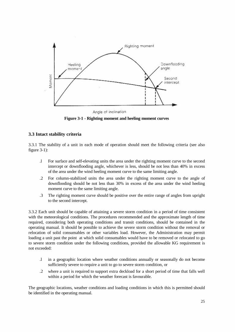
Figure 3-1 - Righting moment and heeling moment curves
3.3 Intact stability criteria
3.3.1 The stability of a unit in each mode of operation should meet the following criteria (see alsofigure 3-1):
.l For surface and self-elevating units the area under the righting moment curve to the secondintercept or downflooding angle, whichever is less, should be not less than 40% in excessof the area under the wind heeling moment curve to the same limiting angle.
.2 For column-stabilized units the area under the righting moment curve to the angle ofdownflooding should be not less than 30% in excess of the area under the wind heelingmoment curve to the same limiting angle.
.3 The righting moment curve should be positive over the entire range of angles from uprightto the second intercept.
3.3.2 Each unit should be capable of attaining a severe storm condition in a period of time consistentwith the meteorological conditions. The procedures recommended and the approximate length of timerequired, considering both operating conditions and transit conditions, should be contained in theoperating manual. It should be possible to achieve the severe storm condition without the removal orrelocation of solid consumables or other variables load. However, the Administration may permitloading a unit past the point at which solid consumables would have to be removed or relocated to goto severe storm condition under the following conditions, provided the allowable KG requirement isnot exceeded:
.l in a geographic location where weather conditions annually or seasonally do not becomesufficiently severe to require a unit to go to severe storm condition, or
.2 where a unit is required to support extra deckload for a short period of time that falls wellwithin a period for which the weather forecast is favourable.
The geographic locations, weather conditions and loading conditions in which this is permitted shouldbe identified in the operating manual.

26
3.3.3 Alternative stability criteria may be considered by the Administration provided an equivalentlevel of safety is maintained and if they are demonstrated to afford adequate positive initial stability. Indetermining the acceptability of such criteria, the Administration should consider at least the followingand take into account as appropriate:
.l environmental conditions representing realistic winds (including gusts) and wavesappropriate for world-wide service in various modes of operation;
.2 dynamic response of a unit. Analysis should include the results of wind tunnel tests, wavetank model tests, and non-linear simulation, where appropriate. Any wind and wave spectraused should cover sufficient frequency ranges to ensure that critical motion responses areobtained;
.3 potential for flooding taking into account dynamic responses in a seaway;
.4 susceptibility to capsizing considering the unit's restoration energy and the static inclinationdue to the mean wind speed and the maximum dynamic response;
.5 an adequate safety margin to account for uncertainties.
3.4 Subdivision and damage stability
Surface and self-elevating units
3.4.1 The unit should have sufficient freeboard and be subdivided by means of watertight decks andbulkheads to provide sufficient buoyancy and stability to withstand in general the flooding of any onecompartment in any operating or transit condition consistent with the damage assumptions set out in3.5.
3.4.2 The unit should have sufficient reserve stability in a damaged condition to withstand the windheeling moment based on a wind velocity of 25.8 m/s (50 knots) superimposed from any direction. Inthis condition the final waterline, after flooding, should be below the lower edge of any downfloodingopening.
Column-stabilized units
3.4.3 The unit should have sufficient freeboard and be subdivided by means of watertight decks andbulkheads to provide sufficient buoyancy and stability to withstand a wind heeling moment induced bya wind velocity of 25.8 m/s (50 knots) superimposed from any direction in any operating or transitcondition, taking the following considerations into account:
.l the angle of inclination after the damage set out in 3.5.10.2 should not be greater than 17°;
.2 any opening below the final waterline should be made watertight, and openings within 4 mabove the final waterline should be made weathertight;
.3 the righting moment curve, after the damage set out above, should have, from the firstintercept to the lesser of the extent of weathertight integrity required by 3.4.3.2 and thesecond intercept, a range of at least 7°. Within this range, the righting moment curve shouldreach a value of at least twice the wind heeling moment curve, both being measured at thesame angle. See figure 3-2 below.

27
Figure 3-2 - Righting moment and wind heeling moment curves
3.4.4 The unit should provide sufficient buoyancy and stability in any operating or transit condition towithstand the flooding of any watertight compartment wholly or partially below the waterline inquestion, which is a pump-room, a room containing machinery with a salt water cooling system or acompartment adjacent to the sea, taking the following considerations into account:
.1 the angle of inclination after flooding should not be greater than 25°;
.2 any opening below the final waterline should be made watertight;
.3 a range of positive stability should be provided, beyond the calculated angle of inclination inthese conditions, of at least 7°.
All types of units
3.4.5 Compliance with the requirements of 3.4.1 to 3.4.4 should be determined by calculations whichtake into consideration the proportions and design characteristics of the unit and the arrangements andconfiguration of the damaged compartments. In making these calculations, it should be assumed thatthe unit is in the worst anticipated service condition as regards stability and is floating free of mooringrestraints.
3.4.6 The ability to reduce angles of inclination by pumping out or ballasting compartments orapplication of mooring forces, etc., should not be considered as justifying any relaxation of therequirements.

28
3.4.7 Alternative subdivision and damage stability criteria may be considered for approval by theAdministration provided an equivalent level of safety is maintained. In determining the acceptability ofsuch criteria, the Administration should consider at least the following and take into account:
.1 extent of damage as set out in 3.5;
.2 on column-stabilized units, the flooding of any one compartment as set out in 3.4.4;
.3 the provision of an adequate margin against capsizing.
3.5 Extent of damage
Surface units
3.5.1 In assessing the damage stability of surface units, the following extent of damage should beassumed to occur between effective watertight bulkheads:
.l horizontal penetration: 1.5 m; and
.2 vertical extent: from the base line upwards without limit.
3.5.2 The distance between effective watertight bulkheads or their nearest stepped portions which arepositioned within the assumed extent of horizontal penetration should be not less than 3.0 m; wherethere is a lesser distance, one or more of the adjacent bulkheads should be disregarded.
3.5.3 Where damage of a lesser extent than in 3.5.1 results in a more severe condition, such lesserextent should be assumed.
3.5.4 All piping, ventilation systems, trunks, etc., within the extent of damage referred to in 3.5.1should be assumed to be damaged. Positive means of closure should be provided at watertightboundaries to preclude the progressive flooding of other spaces which are intended to be intact.
Self-elevating units
3.5.5 In assessing the damage stability of self-elevating units, the following extent of damage shouldbe assumed to occur between effective watertight bulkheads:
.l horizontal penetration: 1.5 m; and
.2 vertical extent: from the base line upwards without limit.
3.5.6 The distance between effective watertight bulkheads or their nearest stepped portions which arepositioned within the assumed extent of horizontal penetration should be not less than 3.0 m; wherethere is a lesser distance, one or more of the adjacent bulkheads should be disregarded.
3.5.7 Where damage of a lesser extent than in 3.5.5 results in a more severe condition, such lesserextent should be assumed.
3.5.8 Where a mat is fitted, the above extent of damage should be applied to both the platform andthe mat but not simultaneously, unless deemed necessary by the Administration due to their closeproximity to each other.

29
3.5.9 All piping, ventilation systems, trunks, etc. within the extent of damage referred to in 3.5.5should be assumed to be damaged. Positive means of closure should be provided at watertightboundaries to preclude the progressive flooding of other spaces which are intended to be intact.
Column-stabilized units
3.5.10 In assessing the damage stability of column-stabilized units, the following extent of damageshould be assumed:
.l Only those columns, underwater hulls and braces on the periphery of the unit should beassumed to be damaged and the damage should be assumed in the exposed portions of thecolumns, underwater hulls and braces.
.2 Columns and braces should be assumed to be flooded by damage having a vertical extent of3.0 m occurring at any level between 5.0 m above and 3.0 m below the draughts specified inthe operating manual. Where a watertight flat is located within this region, the damage shouldbe assumed to have occurred in both compartments above and below the watertight flat inquestion. Lesser distances above or below the draughts may be applied to the satisfaction ofthe Administration, taking into account the actual operating conditions. However, the requireddamage region should extend at least 1.5 m above and below the draught specified in theoperating manual.
.3 No vertical bulkhead should be assumed to be damaged, except where bulkheads are spacedcloser than a distance of one eighth of the column perimeter at the draught underconsideration, measured at the periphery, in which case one or more of the bulkheads shouldbe disregarded.
.4 Horizontal penetration of damage should be assumed to be 1.5 m.
.5 Underwater hull or footings should be assumed to be damaged when operating in a transitcondition in the same manner as indicated in 3.5.10.1, 3.5.10.2, 3.5.10.4 and either 3.5.10.3or 3.5.6, having regard to their shape.
.6 All piping, ventilation systems, trunks, etc., within the extent of damage should be assumed tobe damaged. Positive means of closure should be provided at watertight boundaries topreclude the progressive flooding of other spaces which are intended to be intact.
3.6 Watertight integrity
3.6.1 The number of openings in watertight subdivisions should be kept to a minimum compatiblewith the design and proper working of the unit. Where penetrations of watertight decks and bulkheadsare necessary for access, piping, ventilation, electrical cables, etc., arrangements should be made tomaintain the watertight integrity of he enclosed compartments.
3.6.2 Where valves are provided at watertight boundaries to maintain watertight integrity, these valvesshould be capable of being operated from a pump-room or other normally manned space, a weatherdeck, or a deck which is above the final waterline after flooding. In the case of a column-stabilizedunit this would be the central ballast control station. Valve position indicators should be provided atthe remote control station.

30
3.6.3 For self-elevating units the ventilation system valves required to maintain watertight integrityshould be kept closed when the unit is afloat. Necessary ventilation in this case should be arranged byalternative approved methods.
Internal openings
3.6.4 The means to ensure the watertight integrity of internal openings should comply with thefollowing:
.l Doors and hatch covers which are used during the operation of the unit while afloat should beremotely controlled from the central ballast control station and should also be operable locallyfrom each side. Open/shut indicators should be provided at the control station.
.2 Doors or hatch covers which are normally closed while the unit is afloat should be providedwith an alarm system (e.g. light signals) showing personnel both locally and at the centralballast control station whether the doors or hatch covers in question are open or closed. Anotice should be affixed to each such door or hatch cover stating that it Is not to be left openwhile the unit is afloat.
3.6.5 The means to ensure the watertight integrity of internal openings which are kept permanentlyclosed during the operation of the unit, while afloat, should comply with the following:
l A notice should be affixed to each such closing appliance stating that it is to be kept closedwhile the unit is afloat; however, manholes fitted with close bolted covers need not be somarked.
.2 On self-elevating units, an entry should be made in the official log-book or tour report, asapplicable, stating that all such openings have been witnessed closed before the unit becomeswaterborne.
External openings
3.6.6 All downflooding openings the lower edge of which is submerged when the unit is inclined to thefirst intercept between the righting moment and wind heeling moment curves in any intact or damagedcondition should be fitted with a suitable watertight closing appliance, such as closely spaced boltedcovers.
3.6.7 Where flooding of chain lockers or other buoyant volumes may occur, the openings to thesespaces should be considered as downflooding points.
3.7 Freeboard
General
3.7.1 The requirements of the 1966 Load Line Convention, including those relating to certification,should apply to ail units and certificates should be issued as appropriate. The minimum freeboard ofunits which cannot be computed by the normal methods laid down by that Convention should bedetermined on the basis of meeting the applicable intact stability, damage stability and structuralrequirements for transit conditions and drilling operations while afloat. The freeboard should not beless than that computed from the Convention where applicable.

31
3.7.2 The requirements of the 1966 Load Line Convention with respect to weathertightness andwatertightness of decks, superstructures, deckhouses, doors, hatchway covers, other openings,ventilators, air pipes, scuppers, inlets and discharges, etc., should be taken as a basis for all units inthe afloat condition.
3.7.3 In general, heights of hatch and ventilator coamings, air pipes, door sills, etc., in exposedpositions and their means of closing should be determined by consideration of both intact and damagestability requirements.
3.7.4 All downflooding openings which may become submerged before the angle of inclination atwhich the required area under the intact righting arm curve is achieved should be fitted withweathertight closing appliances.
3.7.5 With regard to damage stability, the requirements in 3.4.3.2, 3.4.4 and 3.6.6 should apply.
3.7.6 Administrations should give special consideration to the position of openings which cannot beclosed in emergencies, such as air intakes for emergency generators, having regard to the intactrighting arm curves and the final waterline after assumed damage.
Surface units
3.7.7 Load lines should be assigned to surface units as calculated under the terms of the 1966 LoadLine Convention and should be subject to all the conditions of assignment of that Convention.
3.7.8 Where it is necessary to assign a greater than minimum free board to meet intact or damagestability requirements or on account of any other restriction imposed by the Administration, regulation6(6) of the 1966 Load Line Convention should apply. When such a freeboard is assigned, seasonalmarks above the centre of the ring should not be marked and any seasonal marks below the centre ofthe ring should be marked. If a unit is assigned a greater than minimum freeboard at the request of theowner, regulation 6(6) need not apply.
3.7.9 Where moonpools are arranged within the hull in open communication with the sea, the volumeof the moonpool should not be included in the calculation of any hydrostatic properties. If themoonpool has a larger cross-sectional area above the waterline at 0.85D than below, an additionshould be made to the geometric freeboard corresponding to the lost buoyancy. This addition for theexcess portion above the waterline at 0.85D should be made as prescribed below for wells or recesses.If an enclosed superstructure contains part of the moonpool, deduction should be made for theeffective length of the superstructure. Where open wells or recesses are arranged in the freeboarddeck, a correction equal to the volume of the well or recess to the freeboard deck divided by thewaterplane area at 0.85D should be made to the freeboard obtained after all other corrections, exceptbow height correction, have been made. Free surface effects of the flooded well or recess should betaken into account in stability calculations.
3.7.10 The procedure described in 3.7.9 should also apply in cases of small notches or relativelynarrow cut-outs at the stern of the unit.
3.7.11 Narrow wing extensions at the stern of the unit should be considered as appendages andexcluded for the determination of length (L) and for the calculation of freeboards. The Administrationshould determine the effect of such wing extensions with regard to the requirements for the strength ofunit based upon length (L).
32
Self-elevating units
3.7.12 Load lines should be assigned to self-elevating units as calculated under the terms of the 1966Load Line Convention. When floating or when in transit from one operational area to another unitsshould be subject to all the conditions of assignment of that Convention unless specifically excepted.However, these units should not be subject to the terms of that Convention while they are supported bythe sea-bed or are in the process of lowering or raising their legs.
3.7.13 The minimum freeboard of units which due to their configuration cannot be computed by thenormal methods laid down by the 1966 Load Line Convention should be determined on the basis ofmeeting applicable intact stability, damage stability and structural requirements in the afloat condition.
3.7.14 Where it is necessary to assign a greater than minimum freeboard to meet intact or damagestability requirements or on account of any other restriction imposed by the Administration, regulation6(6) of the 1966 Load Line Convention should apply. When such a freeboard is assigned, seasonalmarks above the centre of the ring should not be marked and any seasonal marks below the centre ofthe ring should be marked. If a unit is assigned a greater than minimum freeboard at the request of theowner, regulation 6(6) need not apply.
3.7.15 Where moonpools are arranged within the hull in open communication with the sea, the volumeof the moonpool should not be included in the calculation of any hydrostatic properties. If themoonpool has a larger cross-sectional area above the waterline at 0.85D than below, an additionshould be made to the geometric freeboard corresponding to the lost buoyancy. This addition for theexcess portion above the waterline at 0.85D should be made as prescribed below for wells or recesses.If an enclosed superstructure contains part of the moonpool, deduction should be made for theeffective length of the superstructure. Where open wells or recesses are arranged in the freeboarddeck, a correction equal to the volume of the well or recess to the freeboard deck divided by thewaterplane area at 0.85D, should be made to the freeboard obtained after all other corrections, exceptbow height correction have been made. Free surface effects of the flooded well or recess should betaken into account in stability calculations.
3.7.16 The procedure described in 3.7.15 should apply in cases of small notches or relatively narrowcut-outs at the stern of the unit.
3.7.17 Narrow wing extensions at the stern of the unit should be considered as appendages andexcluded for the determination of length (L) and for the calculation of freeboards. The Administrationshould determine the effect of such wing extensions with regard to the requirements for the strength ofunit based upon length (L).
3.7.18 Self-elevating units may be manned when under tow. In such cases a unit would be subject to abow height requirement which may not always be possible to achieve. In such circumstances, theAdministration should consider the extent of application of regulation 39(3) of the 1966 Load LineConvention to such units, having regard to the occasional nature of such voyages on predeterminedroutes and to prevailing weather conditions.
3.7.19 Some self-elevating units utilize a large mat or similar supporting structure which contributesto the buoyancy when the unit is floating. In such cases the mat or similar supporting structure shouldbe ignored in the calculation of freeboard. The mat or similar supporting structure should, however,always be taken into account in the evaluation of the stability of the unit when floating since itsvertical position relative to the upper hull may be critical.

33
Column-stabilized units,
37.20 The hull form of this type of unit makes the calculation of geometric freeboard in accordancewith the provisions of chapter III of the 1966 Load Line Convention impracticable. Therefore theminimum freeboard of each column-stabilized unit should be determined by meeting the applicablerequirements for:
.1 the strength of the unit's structure;
.2 the minimum clearance between passing wave crests and deck structure (see 2.6.1 to2.6.3); and
.3 intact and damage stability requirements.
3.7.21 The minimum freeboard should be marked in appropriate locations on the structure.
3.7.22 The enclosed deck structure of each column-stabilized unit should be made weathertight.
3.7.23 Windows, sidescuttles and portlights, including those of the non-opening type, or other similaropenings should not be located below the deck structure of column-stabilized units.
3.7.24 Administrations should give special consideration to the position of openings which cannot beclosed in emergencies, such as air intakes for emergency generators, having regard to the intactrighting arm curves and the final waterline after assumed damage.
CHAPTER 4 - MACHINERY INSTALLATIONS FOR ALL TYPES OF UNITS
4.1 General
4.1.1 The machinery and electrical requirements contained in chapters 4 to 8 provide an acceptabledegree of protection for personnel from fire, electric shock or other physical injuries. The requirementsapply to both marine and industrial equipment.
4.1.2 Codes and standards of practice which have been proven to be effective by actual application bythe offshore drilling industry which are not in conflict with this Code, and which are acceptable to theAdministration, may be applied in addition to these requirements.
4.1.3 All machinery, electrical equipment, boilers and other pressure vessels, associated pipingsystems, fittings and wiring should be of a design and construction adequate for the service for whichthey are intended and should be so, installed and protected as to reduce to a minimum any danger topersons on board, due regard being paid to moving parts, hot surfaces and other hazards. The designshould have regard to materials used in construction, and to the marine and industrial purposes forwhich the equipment is intended, the working conditions and the environmental conditions to which itwill be subjected. Consideration should be given to the consequences of the failure of systems andequipment essential to the safety of the unit.
4.1.4 All machinery, components and systems essential to the safe operation of a unit should bedesigned to operate under the following static conditions of inclination:

34
.1 when column-stabilized units are upright and inclined to an angle up to 15° in anydirection;
.2 when self-elevating units are upright and inclined to an angle up to 10° in any direction;
.3 when surface units are upright and in level trim and when inclined to an angle of list up to15° either way and simultaneously trimmed to an angle up to 5° by the bow or stern.
The Administration may permit or require deviations from these angles, taking into consideration thetype, size and service conditions of the unit.
4.1.5 Jacking mechanisms for self-elevating units are in general to be arranged with redundancy sothat a single failure of any component does not cause an uncontrolled descent of the unit.
4.2 Machinery requirements
4.2.1 All boilers, all parts of machinery, all steam, hydraulic, pneumatic and other systems and theirassociated fittings which are under internal pressure should be subjected to appropriate tests includinga pressure test before being put into service for the first time.
4.2.2 Adequate provisions should be made to facilitate cleaning, inspection and maintenance ofmachinery including boilers and pressure vessels.
4.2.3 Where risk from overspeeding of machinery exists, means should be provided to ensure that thesafe speed is not exceeded.
4.2.4 Where machinery including pressure vessels or any parts of such machinery are subject tointernal pressure and may be subject to dangerous overpressure, means should, where applicable, beprovided which will protect against such excessive pressure.
4.2.5 All gearing and every shaft and coupling used for transmission of power to machinery essentialfor the safety of the unit or persons on board should be designed and constructed so that they willwithstand the maximum working stresses to which they may be subjected in all service conditions,taking into account the type of engines by which they are driven or of which they form part.
4.2.6 Internal combustion engines of a cylinder diameter of 200 mm or a crankcase volume of 0.6 m³and above should be provided with crankcase explosion relief valves of an approved type withsufficient relief area. The relief valves should be arranged or provided with means to ensure thatdischarge from them is directed so as to minimize the possibility of injury to personnel.
4.2.7 Machinery, where applicable, should be provided with automatic shutoff arrangements or alarmsin the case of failures, such as lubricating oil supply failure, which could lead rapidly to completebreakdown, damage or explosion. The Administration may permit revisions for overriding automaticshutoff devices.
4.2.8 Means should be provided whereby normal operation of vital systems, such as ballast systems insemisubmersible units, jacking systems in self-elevating units or control of blow-out preventers, can besustained or restored even though one of the essential auxiliaries becomes inoperable.

35
4.2.9 Means should be provided to ensure that machinery can be brought into operation from the"dead ship" condition without external aid.
4.3 Steam boilers and boiler feed systems
4.3.1 Every steam boiler and every unfired steam generator should be provided with not less than twosafety valves of adequate capacity. However, the Administration may, having regard to the output orany other features of any boiler or unfired steam generator, permit only one safety valve to be fitted ifit is satisfied that adequate protection against overpressure is provided.
4.3.2 Every oil-fired boiler which is intended to operate without manual supervision should havesafety arrangements which shut off the fuel supply and give an alarm at an attended location in thecase of low water level, air supply failure or flame failure.
4.3.3 Every steam generating system which could be rendered dangerous by the failure of its feedwatersupply, should be provided with not less than two separate feedwater systems from and including thefeed pumps, noting that a single penetration of the steam drum is acceptable. For those services notessential for the safety of the unit, only one feedwater system is required if automatic shutdown of thesteam generating system upon loss of the feedwater supply is provided. Means should be providedwhich will prevent overpressure in any part of the feedwater system.
4.3.4 Boilers should be provided with means to supervise and control the quality of the feedwater. Asfar as practicable, means should be provided to preclude the entry of oil or other contaminants whichmay adversely affect the boiler.
4.3.5 Every boiler essential for the safety of the unit and which is designed to have a water levelshould be provided with at least two means for indicating its water level, at least one of which shouldbe a direct reading gauge glass.
4.4 Steam pipe systems
4.4.1 Every steam pipe and every fitting connected thereto through which steam may pass should be sodesigned, constructed and installed as to withstand the maximum working stresses to which it may besubjected.
4.4.2 Efficient means should be provided for draining every steam pipe where dangerous waterhammer action might otherwise occur.
4.4.3 If a steam pipe or fitting may receive steam from any source at a higher pressure than that forwhich it is designed, a suitable reducing valve, relief valve and pressure gauge should be fitted.
4.5 Machinery controls
4.5.1 Machinery essential for the safety of the unit should be provided with effective means for itsoperation and control.
4.5.2 Automatic starting, operational and control systems for machinery essential for the safety of theunit should, in general, include provisions for manually overriding the automatic controls. Failure ofany part of the automatic and remote control system should not prevent the use of the manual override.Visual indication should be provided to show whether or not the override has been actuated.

36
4.6 Air pressure systems
4.6.1 In every unit means should be provided to prevent excess pressure in any part of compressed airsystems and where water jackets or casings of air compressors and coolers might be subjected todangerous excess pressure due to leakage into them from air pressure parts. Suitable pressure reliefarrangements should be provided for all systems.
4.6.2 The starting air arrangements for internal combustion engines should be adequately protectedagainst the effects of backfiring and internal explosions in the starting air pipes.
4.6.3 Starting air pipes from the air receivers to internal combustion engines should be entirelyseparate from the compressor discharge pipe system.
4.6.4 Provision should be made to reduce to a minimum the entry of oil into the starting air pressuresystems and to drain these systems.
4.7 Arrangements for oil fuel, lubricating oil and other flammable oils.
4.7.1 Arrangements for the storage, distribution and utilization of oil fuel should be such as to ensurethe safety of the unit and persons on board.
4.7.2 Arrangements for the storage, distribution and utilization of oil used in pressure lubricationsystems should be such as to ensure the safety of the unit and persons on board.
4.7.3 Arrangements for the storage, distribution and utilization of other flammable oils employedunder pressure in power transmission systems, control and activating systems and heat transfersystems should be such as to ensure the safety of the unit and persons on board.
4.7.4 In machinery spaces pipes, fittings and valves carrying flammable oils should be of a materialapproved by the Administration, having regard to the risk of fire.
4.8 Bilge pumping arrangements
4.8.1 An efficient bilge pumping system should be provided, capable of pumping from and drainingwatertight compartments other than spaces permanently appropriated for the carriage of fresh water,water ballast, oil fuel or liquid cargo and for which other efficient means of pumping are provided,under all practical conditions whether the unit is upright or inclined, as specified in 4.1.4. Additionalsuctions should be provided in large compartments or compartments of unusual form, as deemednecessary by the Administration. Arrangements should be made whereby water in the compartmentmay find its way to the suction pipes. Compartments not provided with a bilge suction may be drainedto other spaces provided with bilge pumping capability. Means should be provided to detect thepresence of water in such compartments which are adjacent to the sea or adjacent to tanks containingliquids and in void compartments through which pipes conveying liquids pass. If the Administration issatisfied that the safety of the unit is not impaired, the bilge pumping arrangements and the means todetect the presence of water may be dispensed with in particular compartments.
4.8.2 At least two self-priming power pumps connected to each bilge main should be provided.Sanitary, ballast and general service pumps may be accepted as independent power bilge pumps iffitted with the necessary connections to the bilge pumping system.

37
4.8.3 All bilge pipes should be of steel or other suitable material having properties acceptable to theAdministration. Special consideration should be given to the design of bilge lines passing throughballast tanks taking into account effects of corrosion or other deterioration.
4.8.4 The arrangement of the bilge pumping system should be such as to prevent the possibility ofwater passing from the sea into dry spaces, or inadvertently from one compartment to another.
4.8.5 All distribution boxes and manually operated valves in connection with the bilge pumpingarrangements should be in positions which are accessible under ordinary circumstances. Where suchvalves are located in normally unmanned spaces below the assigned load line and not provided withhigh bilge water level alarms, they should be operable from outside the space.
4.8.6 A means to indicate whether a valve is open or closed should be provided at each location fromwhich the valve can be controlled. The indicator should rely on movement of the valve spindle.
4.8.7 Drainage of hazardous areas should be given special consideration having regard to the risk ofexplosion (see 6.3.2).
4.8.8 The following additional requirements are applicable to column-stabilized units:
.1 Chain lockers which, if flooded, could substantially affect the unit's stability should beprovided with a remote means to detect flooding and a permanently installed means ofdewatering. Remote indication of flooding should be provided at the central ballast controlstation.
.2 At least one of the pumps referred to in 4.8.2 and pump-room bilge suction valves shouldbe capable of both remote and local operation.
.3 Propulsion rooms and pump-rooms in lower hulls should be provided with two independentsystems for high bilge water level detection providing an audible and visual alarm at thecentral ballast control station.
4.9 Ballast pumping arrangements on column-stabilized units
Ballast pumps and piping
4.9.1 Units should be provided with an efficient pumping system capable of ballasting anddeballasting any ballast tank under normal operating and transit conditions. Alternatively,Administrations may permit controlled gravity ballasting.
4.9.2 The ballast system should provide the capability to bring the unit, while in an intact condition,from the maximum normal operating draught to a severe storm draught, or to a greater distance, asmay be specified by the Administration, within 3 hours.
4.9.3 The ballast system should be arranged to provide at least two independent pumps so that thesystem remains operational in the event of failure of any one such pump. The pumps provided neednot be dedicated ballast pumps, but should be readily available for such use at all times.
4.9.4 The ballast system should be capable of operating after the damage specified in 3.5.10 and havethe capability of restoring the unit to a level trim and safe draught condition without taking onadditional ballast, with any one pump inoperable. The Administration may permit counter-flooding asan operational procedure.

38
4.9.5 The ballast system should be arranged and operated so as to prevent inadvertent transfer ofballast water from one tank or hull to another, which could result in moment shifts leading toexcessive angles of heel or trim.
4.9.6 It should be possible to supply each ballast pump required by 4.9.3 from the emergency sourceof power. The arrangements should be such that the system is capable of restoring the unit from aninclination specified in 4.1.4.1 to a level trim and safe draught condition after loss of any singlecomponent in the power supply system.
4.9.7 All ballast pipes should be of steel or other suitable material having properties acceptable to theAdministration. Special consideration should be given to the design of ballast lines passing throughballast tanks, taking into account effects of corrosion or other deterioration.
4.9.8 All valves and operating controls should be clearly marked to identify the function they serve.Means should be provided locally to indicate whether a valve is open or closed.
4.9.9 Air pipes should be provided on each ballast tank sufficient in number and cross sectional areato permit the efficient operation of the ballast pumping system under the conditions referred to in 4.9.1to 4.9.9. In order to allow deballasting of the ballast tanks intended to be used to bring the unit back tonormal draught and to ensure no inclination after damage, air pipe openings for these tanks should beabove the worst damage waterline specified in chapter 3. Such air pipes should be positioned outsidethe extent of damage, as defined in chapter 3.
Control and indicating systems
4.9.10 A central ballast control station should be provided. It should be located above the worstdamage waterline and in a space not within the assumed extent of damage referred to in chapter 3 andadequately protected from weather. It should be provided with the following control and indicatingsystems where applicable:
.l ballast pump control system;
.2 ballast pump status-indicating system;
.3 ballast valve control system;
.4 ballast valve position-indicating system;
.5 tank level indicating system;
.6 draught indicating system;
.7 heel and trim indicators;
.8 power availability indicating system (main and emergency);
.9 ballast system hydraulic/pneumatic pressure-indicating system.
4.9.11 In addition to remote control of the ballast pumps and valves from the central ballast controlstation, all ballast pumps and valves should be fitted with independent local control operable in theevent of remote control failure. The independent local control of each ballast pump and of itsassociated ballast tank valves should be in the same location.
4.9.12 The control and indicating systems listed in 4.9.10 should function independently of oneanother, or have sufficient redundancy, such that a failure in one system does not jeopardize theoperation of any of the other systems.

39
4.9.13 Each power-actuated ballast valve should fail to the closed position upon loss of control power.Upon reactivation of control power, each such valve should remain closed until the ballast controloperator assumes control of the reactivated system. The Administration may accept ballast valvearrangements that do not fail to the closed position upon loss of power provided the Administration issatisfied that the safety of the unit is not impaired.
4.9.14 The tank level indicating system required by 4.9.10.5 should provide means to:
.1 indicate liquid levels in all ballast tanks. A secondary means of determining levels inballast tanks, which may be a sounding pipe, should be provided. Tank level sensorsshould not be situated in the tank suction lines;
.2 indicate liquid levels in other tanks, such as fuel oil, fresh water, drilling water or liquidstorage tanks, the filling or emptying of which, in the view of the Administration couldaffect the stability of the unit. Tank level sensors should not be situated in the tank suctionlines.
4.9.15 The draught indicating system should indicate the draught at each corner of the unit or atrepresentative positions as required by the Administration.
4.9.16 Enclosures housing ballast system electrical components, the failure of which would causeunsafe operation of the ballast system upon liquid entry into the enclosure, should comply with 5.5.21.
4.9.17 A means to indicate whether a valve is open or closed should be provided at each location fromwhich the valve can be controlled. The indicators should rely on movement of the valve spindle..
4.9.18 Means should be provided at the central ballast control station to isolate or disconnect theballast pump control and ballast valve control systems from their sources of electrical, pneumatic orhydraulic power.
Internal communication
4.9.19 A permanently installed means of communication, independent of the unit's main source ofelectrical power, should be provided between the central ballast control station and spaces that containballast pumps or valves, or other spaces that may contain equipment necessary for the operation of theballast system.
4.10 Protection against flooding
4.10.1 Each seawater inlet and discharge in spaces below the assigned load line should be providedwith a valve operable from an accessible position outside the space on:
.1 all column-stabilized units;
.2 all other units where the space containing the valve is normally unattended and is notprovided with high bilge water level detection.
4.10.2 The control systems and indicators provided in 3.6.4.1 should be operable in both normalconditions and in the event of main power failure. Where stored energy is provided for this purpose, itscapacity should be to the satisfaction of the Administration.

40
4.11 Anchoring arrangements for surface and column-stabilized units
4.11.1 Anchoring arrangements, where fitted as the sole means for position keeping, should beprovided with adequate factors of safety and be designed to maintain the unit on station in all designconditions. The arrangements should be such that a failure of any single component should not causeprogressive failure of the remaining anchoring arrangements.
4.11.2 The anchors, cables, shackles and other associated connecting equipment should be designed,manufactured and tested in accordance with a recognized standard. Evidence, to the satisfaction of theAdministration, that the equipment has been so tested and approved should be readily available.Provisions should be made on board for the recording of changes to and inspection of the equipment.
4.11.3 Anchor cables may be of wire, rope, chain or any combination thereof.
4.11.4 Means should be provided to enable the anchor cable to be released from the unit after loss ofmain power.
4.11.5 Fairleads and sheaves should be designed to prevent excessive bending and wear of the anchorcable. The attachments to the hull or structure should be such as to adequately withstand the stressesimposed when an anchor cable is loaded to its breaking strength.
4.11.6 Suitable anchor stowage arrangements should be provided to prevent movement of the anchorsin a seaway.
4.11.7 Each windlass should be provided with two independent power-operated brakes. Each brakeshould be capable of holding against a static load in the anchor cable of at least 50% of its breakingstrength. Where the Administration so allows, one of the brakes may be replaced by a manuallyoperated brake.
4.11.8 The design of the windlass should provide for adequate dynamic braking capacity to controlnormal combinations of loads from the anchor, anchor cable and anchor handling vessel during thedeployment of the anchors at the maximum design payout speed of the windlass.
4.11.9 On loss of power to the windlasses, the power-operated braking system should be automaticallyapplied and be capable of holding against 50% of the total static braking capacity of the windlass
4.11.10 Each windlass should be capable of being controlled from a position which provides a goodview of the operation.
4.11.11 Means should be provided at the windlass control position to monitor cable tension andwindlass power load and to indicate the amount of cable paid out.
4.11.12 A manned control station should be provided with means to indicate cable tensions and speedand direction of wind.
4.11.13 Reliable means should be provided to communicate between locations critical to the anchoringoperation.
4.11.14 Special consideration should be given to arrangements where the anchoring systems providedare used in conjunction with thrusters to maintain the unit on station.

41
4.12 Dynamic positioning systems
Dynamic positioning systems used as a sole means of position keeping should provide a level ofsafety equivalent to that provided for anchoring arrangements, to the satisfaction of theAdministration.
CHAPTER 5 - ELECTRICAL INSTALLATIONS FOR ALL TYPES OF UNITS
5.1 General electrical requirements
5.1.1 Electrical installations should be such that:
.1 all electrical services necessary for maintaining the unit in normal operational habitableconditions will be assured without recourse to the emergency source of power;
.2 electrical services essential for safety will be assured in case of failure of the main sourceof electrical power; and
.3 the safety of personnel and unit from electrical hazards will be assured.
5.1.2 Administrations should take appropriate steps to ensure uniformity in the implementation andapplication of the provisions of these requirements in respect of electrical installations 3.
5.2 Main source of electrical power
5.2.1 Every unit should be provided with a main source of electrical power which should include atleast two generating sets.
5.2.2 The power of these sets should be such that it is still possible to ensure the functioning of theservices referred to in 5.1.1.1 except for services referred to in 1.3.17.2, in the event of any one ofthese generating sets being stopped.
5.2.3 Where transformers or converters constitute an essential part of the supply system, the systemshould be so arranged as to ensure the same continuity of the supply as stated in 5.2.2.
5.2.4 A main electrical lighting system which should provide illumination throughout those parts ofthe unit normally accessible to and used by personnel should be supplied from the main source ofpower.
5.2.5 The arrangement of the main lighting system should be such that a fire or other casualty in thespace or spaces containing the main source of power, including transformers or converters, if any, willnot render the emergency lighting system required by 5.3 inoperative.
5.2.6 The arrangement of the emergency lighting system should be such that a fire or other casualty inthe space or spaces containing the emergency source of power, including transformers or converters, ifany, will not render the main lighting system required by this section inoperative.
3 Reference is made to the recommendations published by the International Electrotechnical Commission.

42
5.3 Emergency source of electrical power
5.3.1 Every unit should be provided with a self-contained emergency source of electrical power.
5.3.2 The emergency source of power, the transitional source of emergency power and the emergencyswitchboard should be located above the worst damage waterline and in a space not within theassumed extent of damage referred to in chapter 3, and be readily accessible. They should not beforward of the collision bulkhead, if any.
5.3.3 The location of the emergency source of power, the transitional source of emergency power andemergency switchboard in relation to the main source of electrical power should be such as to ensureto the satisfaction of the Administration that a fire or other casualty in the space containing the mainsource of electrical power or in any machinery space of category A will not interfere with the supplyor distribution of emergency power. As far as practical, the space containing the emergency source ofpower, the transitional source of emergency power and the emergency switchboard should not becontiguous to boundaries of machinery spaces of category A or of those spaces containing the mainsource of electrical power. Where the emergency source of power, the transitional source ofemergency power, and the emergency switchboard are contiguous to the boundaries of machineryspaces of category A or to those spaces containing the main source of electrical power, or to spaces ofzone 1 or zone 2, the contiguous boundaries should be in compliance with 9.1.
5.3.4 Provided that suitable measures are taken for safeguarding independent emergency operationunder all circumstances, the emergency switchboard may be used to supply non-emergency circuits,and the emergency generator may be used exceptionally and for short periods to supply non-emergency circuits.
5.3.5 For units where the main source of electrical power is located in two or more spaces which havetheir own systems, including power distribution and control systems, completely independent of thesystems in the other spaces and such that a fire or other casualty in any one of the spaces will notaffect the power distribution from the others, or to the services required by 5.3.6, the requirements of5.3.1 may be considered satisfied without an additional emergency source of electrical power,provided that the Administration is satisfied that:
.l there are at least two generating sets, meeting the requirements of 5.3.15 and each ofsufficient capacity to meet the requirements of 5.3.6, in each of at least two spaces;
.2 the arrangements required by 5.3.5.1 in each such space are equivalent to those required by5.3.8, 5.3.1 1 to 5.3.14 and 5.4 so that a source of electrical power is available at all timesto the services required by 5.3.6;
.3 the location of each of the spaces referred to in 5.3.5.1 Is in compliance with 5.3.2 and theboundaries meet the requirements of 5.3.3 except that contiguous boundaries shouldconsist of an "A-60" bulkhead and a cofferdam, or a steel bulkhead insulated to class "A-60" on both sides.
5.3.6 The power available should be sufficient to supply all those services that are essential for safetyin an emergency, due regard being paid to such services as may have to be operated simultaneously.The emergency source of power should be capable, having regard to starting currents and thetransitory nature of certain loads, of supplying simultaneously at least the following services for theperiods specified hereinafter, if they depend upon an electrical source for their operation:

43
.1 For a period of 18 hours, emergency lighting:
.1.1 at every embarkation station on deck and over sides;
.1.2 in all service and accommodation alleyways, stairways and exits, personnel lift cars, andpersonnel lift trunks;
.1.3 in the machinery spaces and main generating stations including their control positions;
.1.4 in all control stations and in all machinery control rooms;
.1.5 in all spaces from which control of the drilling process is performed and where controlsof machinery essential for the performance of this process, or devices for emergencyswitching-off of the power plant are located;
.1.6 at the stowage position or positions for firemen's outfits;
.1.7 at the sprinkler pump, if any, at the fire pump referred to in 5.3.6.5, at the emergencybilge pump, if any, and at their starting positions;
.1.8 on helicopter landing decks;
.2 For a period of 18 hours, the navigation lights, other lights and sound signals, required bythe International Regulations for the Prevention of Collisions at Sea, in force;
.3 For a period of 4 days any signalling lights or sound signals which may be required formarking of offshore structures;
.4 For a period of 18 hours:
.4.1 all internal communication equipment that is required in an emergency;
.4.2 fire and gas detection and their alarm systems;
.4.3 intermittent operation of the manual fire alarms and all internal signals that are requiredin an emergency; and
.4.4 the capability of closing the blow-out preventer and of disconnecting the unit from thewell head arrangement, if electrically controlled;
unless they have an independent supply from an accumulator battery suitably located foruse in an emergency and sufficient for the period of 18 hours;
.5 For a period of 18 hours, one of the fire pumps, if dependent upon the emergencygenerator for its source of power;
.6 For a period of at least 18 hours, permanently installed diving equipment, if dependentupon the unit's electrical power;
.7 On column-stabilized units, for a period of 18 hours:
.7.1 ballast control and indicating systems required by 4.9.10; and
.7.2 any of the ballast pumps required by 4.9.3; only one of the connected pumps need beconsidered to be in operation at any time;
.8 For a period of half an hour:
.8.1 power to operate the watertight doors as provided by 3.6.4.1, but not necessarily all ofthem simultaneously, unless an independent temporary source of stored energy isprovided;

44
.8.2 power to operate the controls and indicators required by 3.6.4.1.
5.3.7 The emergency source of power may be either a generator or an accumulator battery.
5.3.8 Where the emergency source of power is a generator it should be:
.l driven by a suitable prime mover with an independent supply of fuel, having a flashpoint ofnot less than 43°
.2 started automatically upon failure of the normal electrical supply unless a transitionalsource of emergency power in accordance with 5.3.8.3 is provided; where the emergencygenerator is automatically started, it should be automatically connected to the emergencyswitchboard; those services referred to in 5.3.10 should then be connected automatically tothe emergency generator; and unless a second independent means of starting the emergencygenerator is provided, the single source of stored energy should be protected to preclude itscomplete depletion by the automatic starting system; and
.3 provided with a transitional source of emergency power, as specified in 5.3.10, unless theemergency generator is capable of supplying the services mentioned in 5.3.10 and of beingautomatically started and supplying the required load as quickly as is safe and practicablebut in not more than 45 seconds.
5.3.9 Where the emergency source of power is an accumulator battery it should be capable of:
.1 carrying the emergency load without recharging while maintaining the voltage of thebattery throughout the discharge period within plus or minus 12% of its nominal voltage;
.2 automatically connecting to the emergency switchboard in the event of failure of the mainpower supply; and
.3 immediately supplying at least those services specified in 5.3.10.
5.3.10 The transitional source or sources of emergency power, where required by 5.3.8.3, shouldconsist of an accumulator battery suitably located for use in an emergency, which should operatewithout recharging whilst maintaining the voltage of the battery throughout the discharge periodwithin plus or minus 12% of its nominal voltage, and be of sufficient capacity and so arranged as tosupply automatically, in the event of failure of either the main or the emergency source of power, thefollowing services for half an hour at least if they depend upon an electrical source for their operation:
.l the lighting required by 5.3.6.1 and 5.3.6.2. For this transitional phase, the requiredemergency lighting, in respect of the machinery space and accommodation and serviceareas, may be provided by permanently fixed, individual accumulator lamps which areautomatically charged and operated;
.2 all essential Internal communication equipment required by 5.3.6.4.1 and 5.3.6.4.2; and
.3 intermittent operation of the services referred to in 5.3.6.4.3 and 5.3.6.4.4,
unless, in the case of 5.3.10.2 and 5.3.10.3, they have an independent supply from an accumulatorbattery suitably located for use in an emergency and sufficient for the period specified.

45
5.3.11 The emergency switchboard should be installed as near as is practicable to the emergencysource of power and, where the emergency source of power is a generator, the emergency switchboardshould preferably be located in the same space.
5.3.12 No accumulator battery fitted in accordance with this requirement for emergency or transitionalpower supply should be installed in the same space as the emergency switchboard, unless appropriatemeasures to the satisfaction of the Administration are taken to extract the gases discharged from thesaid batteries. An indicator should be mounted in a suitable place on the main switchboard or in themachinery control room to indicate when the batteries constituting either the emergency source ofpower or the transitional source of power, referred to in 5.3.9 or 5.3.10, are being
5.3.13 The emergency switchboard should be supplied in normal operation from the main switchboardby an interconnector feeder which should be adequately protected at the main switchboard againstoverload and short circuit. The arrangement at the emergency switchboard should be such that theinterconnector feeder is disconnected automatically at the emergency switchboard upon failure of themain power supply. Where the system is arranged for feedback operation, the interconnector feedershould also be protected at the emergency switchboard at least against short circuit.
5.3.14 In order to ensure ready availability of emergency supplies, arrangements should be madewhere necessary to disconnect non-emergency circuits automatically from the emergency switchboardto ensure that power is available automatically to the emergency circuits.
5.3.15 The emergency generator and its prime mover and any emergency accumulator battery shouldbe designed to function at full rated power when upright and when inclined up to the maximum angleof heel in the intact and damaged condition, as determined in accordance with chapter 3. In no caseneed the equipment be designed to operate when inclined more than:
.1 25° in any direction on a column-stabilized unit;
.2 15° in any direction on a self-elevating unit; and
.3 22.5° about the longitudinal axis and/or when inclined 10° about the transverse axis on asurface unit.
5.3.16 Provision should be made for the periodic testing of the complete emergency system. Thisshould include the testing of automatic starting arrangements.
5.4 Starting arrangements for emergency generators
5.4.1 Emergency generators should be capable of being readily started in their cold condition down toa temperature of 0°C. If this is impracticable, or if lower temperatures are likely to be encountered,consideration should be given to the provision and maintenance of heating arrangements, acceptable tothe Administration, so that ready starting will be assured.
5.4.2 Each emergency generator which is arranged to be automatically started should be equipped withstarting arrangements acceptable to the Administration with a storage energy capability of at leastthree consecutive starts. A second source of energy should be provided for an additional three startswithin 30 minutes unless hand (manual) starting can be demonstrated to be effective.
5.4.3 Provision should be made to maintain the stored energy at all times.

46
5.4.4 Electricalandhydraulicstartingsystemsshouldbemaintainedfromtheemergency switchboard.
5.4.5 Compressed air starting systems may be maintained by the main or auxiliary compressed airreceivers, through a suitable non-return valve or by an emergency air compressor energized by theemergency switchboard.
5.4.6 All of these starting, charging and energy storing devices should be located in the emergencygenerator room; these devices should not be used for any purpose other than the operation of theemergency generator set. This does not preclude the supply to the air receiver of the emergencygenerator set from the main or auxiliary compressed air system through a non-return valve fitted in theemergency generator room.
5.4.7 When automatic starting is not required by these requirements and where it can be demonstratedas being effective, hand (manual) starting is permissible, such as manual cranking, inertia starters,manual hydraulic accumulators, or powder cartridges.
5.4.8 When hand (manual) starting is not practicable, the provisions in 5.4.2 and 5.4.3 to 5.4.6 shouldbe complied with, except that starting may be manually initiated.
5.5 Precautions against shock, fire and other hazards of electrical origin
5.5.1 Exposed metal parts of electrical machines or equipment which are not intended to be live butwhich are liable under fault conditions to become live should be earthed (grounded) unless themachines or equipment are:
.l supplied at a voltage not exceeding 55 V direct current or 55 V, root mean square betweenconductors; auto-transformers should not be used for the purpose of achieving this voltage;or
.2 supplied at a voltage not exceeding 250 V by safety isolating transformers supplying onlyone consuming device; or
.3 constructed in accordance with the principle of double insulation.
5.5.2 The Administration may require additional precautions for portable electrical equipment for usein confined or exceptionally damp spaces where particular risks due to conductivity may exist.
5.5.3 All electrical apparatus should be so constructed and so installed that it does not cause injurywhen handled or touched in the normal manner.
5.5.4 Where not obtained through normal construction, arrangements should be provided to effectivelyearth (ground) all permanently installed machinery, metal structures of derricks, masts and helicopterdecks.
5.5.5 Switchboards should be so arranged as to give easy access, where needed, to apparatus andequipment, in order to minimize danger to personnel. The sides and backs and, where necessary, thefronts of switchboards, should be suitably guarded. Exposed live parts having voltages to earth -(ground). exceeding a voltage to be specified by the Administration should not be installed on the frontof such switchboards. There should be non-conducting mats or gratings at the front and rear, wherenecessary.
5.5.6 Distribution systems with hull return should not be installed, but this does not preclude, underconditions approved by the Administration, the installation of:

47
.1 impressed current cathodic protective systems;
.2 limited and locally earthed systems (e.g. engine starting systems);
.3 limited and locally earthed welding systems; where the Administration is satisfied that theequipotential of the structure is assured in a satisfactory manner, welding systems with hullreturn may be installed without this restriction; and
.4 insulation level monitoring devices provided the circulation current does not exceed 30 mAunder the most unfavourable conditions.
5.5.7 When a distribution system, whether primary or secondary, for power, heating or lighting, withno connection to earth is used, a device capable of continuously monitoring the insulation level to earthand of giving an audible or visual indication of abnormally low insulation values should be provided.
5.5.8 Except as permitted by the Administration in exceptional circumstances, all metal sheaths andarmour of cables should be electrically continuous and should be earthed (grounded).
5.5.9 All electric cables and wiring external to equipment should be at least of a flame-retardant typeand should be so installed as not to impair their original flame-retarding properties 4. Where necessaryfor particular applications, the Administration may permit the use of special types of cables such asradio frequency cables, which do not comply with the foregoing.
5.5.10 Cables and wiring serving essential or emergency power, lighting, internal communications orsignals should, so far as practicable, be routed clear of galleys, machinery spaces of category A andtheir casings and other high fire risk areas. Cables connecting fire pumps to the emergencyswitchboard should be of a fire-resistant type where they pass through high fire risk areas. Wherepracticable all such cables should be run in such a manner as to preclude their being renderedunserviceable by heating of the bulkheads that may be caused by a fire in an adjacent space 4 .
5.5.11 Cables and wiring should be installed and supported in such a manner as to avoid chafing orother damage.
5.5.12 Terminations and joints in all conductors should be so made that they retain the originalelectrical, mechanical, flame-retarding and, where necessary, fire-resisting properties of the cable.
5.5.13 Each separate circuit should be protected against short circuit and against overload, except aspermitted in 7.6, or where the Administration may exceptionally otherwise permit.
5.5.14 The rating or appropriate setting of the overload protection device for each circuit should bepermanently indicated at the location of the protection device.
5.5.15 Lighting fittings should be so arranged as to prevent temperature rises which could damage thecables and wiring, and to prevent surrounding material from becoming excessively hot.
4 Reference is made to the recommendations published by the International Electrotechnical Commission and, inparticular, publication 92 - Electrical installations in ships, concerning flame-retarding properties of bunched cables andcharacteristics of cables of a fire-resistant type.4
48
5.5.16 Accumulator batteries should be suitably housed, and compartments used primarily for theiraccommodation should be properly constructed and efficiently ventilated.
5.5.17 Electrical or other equipment which may constitute a source of ignition of flammable vapoursshould not be permitted in these compartments except as permitted in 5.5.19.
5.5.18 Accumulator batteries, except for batteries of self-contained battery operated lights, should notbe located in sleeping quarters. Administrations may permit relaxations from this requirement wherehermetically sealed batteries are installed.
5.5.19 In paint lockers, acetylene stores, and similar spaces where flammable mixtures are liable tocollect as well as any compartment assigned principally to accumulator batteries, no electricalequipment should be installed unless the Administration is satisfied that such equipment is:
.l essential for operational purposes;
.2 of a type which will not ignite the mixture concerned;
.3 appropriate to the space concerned; and
.4 appropriately certified for safe usage in the vapours or gases likely to be encountered.
5.5.20 Electrical apparatus and cables should, where practicable, be excluded from any compartmentin which explosives are stored. Where lighting is required, the light should come from outside, throughthe boundaries of the compartment. If electrical equipment cannot be excluded from such acompartment it should be so designed and used as to minimize the risk of fire or explosion.
5.5.21 Where spilling or impingement of liquids could occur upon any electrical control or alarmconsole, or similar electrical enclosure essential to the safety of the unit, such equipment should havesuitable protection against the ingress of liquids 5.
5.6 Internal communication
Internal means of communication should be available for transfer of information between all spaceswhere action may be necessary in case of an emergency.
CHAPTER 6 - MACHINERY AND ELECTRICAL INSTALLATIONSIN HAZARDOUS AREAS FOR ALL TYPES OF UNITS
6.1 Zones
Hazardous areas are divided into zones as follows:
Zone 0: in which an explosive gas/air mixture is continuously present or present for long periods.Zone 1: in which an explosive gas/air mixture is likely to occur In normal operation.
5 Reference is made to IEC publication 529: 1976. A standard of at least IP x 2 is suitable. Other arrangements for theenclosures of electrical components may be fitted provided the Administration is satisfied that an equivalent protection isachieved.

49
Zone 2: in which an explosive gas/air mixture is not likely to occur, or in which such a mixture, ifit does occur, will only exist for a short time.
6.2 Classification of hazardous areas 6
6.2.1 For the purpose of machinery and electrical installations, hazardous areas are classified as in6.2.2 to 6.2.4. Hazardous areas not covered in this paragraph should be classified in accordance with6.1.
6.2.2 Hazardous areas zone 0
The internal spaces of closed tanks and pipes for active drilling mud, as well as oil and gasproducts, e.g. escape gas outlet pipes, or spaces in which an oil/gas/air mixture is continuously presentor present for long periods.
6.2.3 Hazardous areas zone 1
.1 Enclosed spaces containing any part of the mud circulating system that has an opening intothe spaces and is between the well and the final degassing discharge.
.2 Enclosed spaces or semi-enclosed locations that are below the drill floor and contain apossible source of release such as the top of a drilling nipple.
.3 Enclosed spaces that are on the drill floor and which are not separated by a solid floorfrom the spaces in 6.2.3.2.
.4 In outdoor or semi-enclosed locations, except as provided for in 6.2.3.2, the area within 1.5m from the boundaries of any openings to equipment which is part of the mud system asspecified in 6.2.3.1, any ventilation outlets of zone 1 spaces, or any access to zone 1spaces.
.5 Pits, ducts or similar structures in locations which would otherwise be zone 2 but whichare so arranged that dispersion of gas may not occur.
6.2.4 Hazardous areas zone 2
.l Enclosed spaces which contain open sections of the mud circulating system from the finaldegassing discharge to the mud pump suction connection at the mud pit.
.2 Outdoor locations within the boundaries of the drilling derrick up to a height of 3 m abovethe drill floor.
.3 Semi-enclosed locations below and contiguous to the drill floor and to the boundaries of thederrick or to the extent of any enclosure which is liable to trap gases.
.4 Outdoor locations below the drill floor and within a radius of 3 m from a possible sourceof release such as the top of a drilling nipple.
.5 The areas 1.5 m beyond the zone 1 areas specified in 6.2.3.4 and beyond the semi-enclosedlocations specified in 6.2.3.2.
6 The identification and extent of hazardous areas in this chapter have been determined taking into account currentpractice.

50
.6 Outdoor areas within 1.5 m of the boundaries of any ventilation outlet from or access to azone 2 space.
.7 Semi-enclosed derricks to the extent of their enclosure above the drill floor or to a height of3 m above the drill floor, whichever is greater.
.8 Air locks between a zone 1 and a non-hazardous area.
6.3 Openings, access and ventilation conditions affecting the extent of hazardous areas
6.3.1 Except for operational reasons, access doors or other openings should not be provided between anon-hazardous space and a hazardous area or between a zone 2 space and a zone 1 space. Where suchaccess doors or other openings are provided, any enclosed space not referred to under 6.2.3 or 6.2.4and having a direct access to any zone 1 location or zone 2 location becomes the same zone as thelocation except that:
.l an enclosed space with direct access to any zone 1 location can be considered as zone 2 if:
.1.1 the access is fitted with a gastight door opening into the zone 2 space, and
.1.2 ventilation is such that the air flow with the door open is from the zone 2 space intothe zone 1 location, and
.1.3 loss of ventilation is alarmed at a manned station;
.2 an enclosed space with direct access to any zone 2 location is not considered hazardous if:
.2.1 the access is fitted with a self-dosing gastight door that opens into the non-hazardouslocation, and
.2.2 ventilation is such that the air flow with the door open is from the non-hazardousspace into the zone 2 location, and
.2.3 loss of ventilation is alarmed at a manned station;
.3 an enclosed space with direct access to any zone 1 location is not considered hazardous if:
.3.1 the access is fitted with self-closing gastight doors forming an air lock, and
.3.2 the space has ventilation overpressure in relation to the hazardous space, and
.3.3 loss of ventilation overpressure is alarmed at a manned station.
Where ventilation arrangements of the intended safe space are considered sufficient by theAdministration to prevent any ingress of gas from the zone 1 location, the two self-closing doorsforming an airlock may be replaced by a single self-closing gastight door which opens into the non-hazardous location and has no hold-back device.
6.3.2 Piping systems should be designed to preclude direct communication between hazardous areas ofdifferent classifications and between hazardous and non-hazardous areas.
6.4 Ventilation of spaces
6.4.1 Hazardous enclosed spaces should be ventilated. Where mechanical ventilation is

51
applied it should be such that the hazardous enclosed spaces are maintained with under pressure inrelation to the less hazardous spaces or areas and non-hazardous enclosed spaces are maintained inoverpressure in relation to adjacent hazardous locations.
6.4.2 All air inlets for hazardous enclosed spaces should be taken from non-hazardous areas. Wherethe inlet duct passes through a more hazardous area the inlet duct should have overpressure in relationto this area.
6.4.3 Each air outlet should be located in an outdoor area which, in the absence of the consideredoutlet, is of the same or lesser hazard than the ventilated space.
6.5 Emergency conditions due to drilling operations
6.5.1 In view of exceptional conditions in which the explosion hazard may extend outside the above-mentioned zones, special arrangements should be provided to facilitate the selective disconnection orshutdown of:
.1 ventilation systems, except fans necessary for supplying combustion air to prime moversfor the production of electrical power;
.2 main generator prime movers, including the ventilation systems for these;
.3 emergency generator prime movers.
6.5.2 Disconnection or shutdown should be possible from at least two strategic locations, one of whichshould be outside hazardous areas.
6.5.3 Shutdown systems that are provided to comply with 6.5.1 should be so designed that the risk ofunintentional stoppages caused by malfunction in a shutdown system and the risk of inadvertentoperation of a shutdown are minimized.
6.5.4 Equipment which is located in spaces other than enclosed spaces and which is capable ofoperation after shutdown as given in 6.5.1 should be suitable for installation in zone 2 locations. Suchequipment which is located in enclosed spaces should be suitable for its intended application to thesatisfaction of the Administration. At least the following facilities should be operable after anemergency shutdown:
- emergency lighting required by 5.3.6.1.1 to 5.3.6.1.4 for half an hour;- blow-out preventer control system;- general alarm system;- public address system; and- battery supplied radiocommunication installations.
6.6 Electrical installations in hazardous areas
6.6.1 Electrical equipment and wiring installed in hazardous areas should be limited to that necessaryfor operational purposes. Only the cables and types of equipment described in this chapter may beinstalled.
6.6.2 Where, in the following, reference is made to certified types of equipment, such equipmentshould be certified as suitable for the flammable gas/air mixture which may be encountered.

52
6.6.3 Cables and types of electrical equipment permitted in hazardous areas are as follows:
.1 Zone 0Certified intrinsically safe circuits or equipment and associated wiring.
.2 Zone 1
.2.1 Certified intrinsically safe circuits or equipment and associated wiring.
.2.2 Certified flameproof (explosion proof) equipment.
.2.3 Certified increased safety equipment; for increased safety motors, due considerationshould be given to the protection against overcurrent.
.2.4 Pressurized-enclosure type equipment which is certified safe or which is to thesatisfaction of the Administration.
.2.5 Through runs of cables.
.3 Zone 2
.3.1 Certified instrinsically safe circuits or equipment and associated wiring.
.3.2 Certified flameproof (explosion proof) equipment.
.3.3 Certified increased safety equipment; for increased safety motors, due considerationshould be given to the protection against overcurrent.
.3.4 Pressurized-enclosure type equipment which is to the satisfaction of the Administration.
.3.5 Any equipment of a type which ensures absence of sparks or arcs and of "hot spots"during normal operation and which is to the satisfaction of the Administration.
.3.6 Through runs of cables.
6.6.4 Permanently installed, fixed cables passing through zone 1 hazardous areas should be fitted witha conductive covering, braiding or sheath for earth detection. Flexible cables passing through suchareas should be to the satisfaction of the Administration.
6.7 Machinery installations in hazardous areas
6.7.1 Mechanical equipment should be limited to that necessary for operational purposes.
6.7.2 Mechanical equipment and machinery in hazardous areas should be so constructed and installedas to reduce the risk of ignition from sparking due to the formation of static electricity or frictionbetween moving parts and from high temperatures of exposed parts due to exhausts or otheremissions.
6.7.3 The installation of internal combustion machinery may be permitted in zone 1 and zone 2hazardous areas, provided that the Administration is satisfied that sufficient precautions have beentaken against the risk of dangerous ignition.
6.7.4 The installation of fired equipment may be permitted in zone 2 hazardous areas, provided thatthe Administration is satisfied that sufficient precaution has been taken 7 against the risk of dangerousignition.
53
CHAPTER 7 - MACHINERY AND ELECTRICAL INSTALLATIONSFOR SELF-PROPELLED UNITS
7.1 General
7.1.1 The requirements of this chapter apply to units which are designed to undertake self-propelledpassages without external assistance and are not applicable to units which are fitted only with meansfor the purpose of positioning or of assistance in towing operations. These requirements are additionalto those in chapters 4, 5 and 6.
7.1.2 Means should be provided whereby normal operation of propulsion machinery can be sustainedor restored even though one of the essential auxiliaries becomes inoperative. Special considerationshould be given to the malfunction of:
.1 a generator set which serves as a main source of electrical power;
.2 the sources of steam supply;
.3 the arrangements for boiler feedwater;
.4 the arrangements which supply fuel oil for boilers or engines;
.5 the sources of lubricating oil pressure;
.6 the sources of water pressure;
.7 a condensate pump and the arrangements to maintain vacuum in condensers;
.8 the mechanical air supply for boilers;
.9 an air compressor and receiver for starting or control purposes; and
.10 the hydraulic, pneumatic or electrical means for control in main propulsion machineryincluding controllable pitch propellers.
However, the Administration, having regard to overall safety considerations, may accept a partialreduction in capability from full normal operation.
7.1.3 Main propulsion machinery and all auxiliary machinery essential to the propulsion and thesafety of the unit should, as fitted in the unit, be capable of operating under the static conditionsrequired by 4.1.4 and the following dynamic conditions:
.1 column-stabilized units 22.5° in any direction;
.2 self-elevating units 15° in any direction;
.3 surface units 22.5° rolling and simultaneously pitching 7.5° by bow or stern.
The Administration may permit deviation from these angles, taking into consideration the type, sizeand service conditions of the unit.
7.1.4 Special consideration should be given to the design, construction and installation of propulsionmachinery systems so that any mode of their vibrations should not cause undue stresses in thismachinery in the normal operating ranges.
7.2 Means of going astern
7.2.1 Units should have sufficient power for going astern to secure proper control of the unit in allnormal circumstances.

54
7.2.2 The ability of the machinery to reverse the direction of thrust of the propeller in sufficient timeand so to bring the unit to rest within a reasonable distance from maximum ahead service speed shouldbe demonstrated.
7.2.3 The stopping times, unit headings and distances recorded on trials, together with the results oftrials to determine the ability of units having multiple propellers to navigate and manoeuvre with oneor more propellers inoperative, should be available on board for the use of the master or otherdesignated personnel 7.
7.2.4 Where the unit is provided with supplementary means for manoeuvring or stopping, these shouldbe demonstrated and recorded as referred to In 7.2.2 and 7.2.3.
7.3 Steam boilers and boiler feed systems
7.3.1 Water tube boilers serving turbine propulsion machinery should be fitted with a high-water-levelalarm.
7.3.2 Every steam generating system which provides services essential for the propulsion of the unitshould be provided with not less than two separate feedwater systems from and including the feedpumps, noting that a single penetration of the steam drum is acceptable. Means should be providedwhich will prevent overpressure in any part of the systems.
7.4 Machinery controls
7.4.1 Main and auxiliary machinery essential for the propulsion of the unit should be provided witheffective means for its operation and control. A pitch indicator should be provided on the navigatingbridge for controllable pitch propellers.
7.4.2 Where remote control of propulsion machinery from the navigating bridge is provided and themachinery spaces are intended to be manned, the following should apply:
.l the speed, direction of thrust and, if applicable, the pitch of the propeller should be fullycontrollable from the navigating bridge under all sailing conditions, includingmanoeuvring;
.2 the remote control should be per-formed, for each independent propeller, by a controldevice so designed and constructed that its operation does not require particular attentionto the operational details of the machinery. Where more than one propeller is designed tooperate simultaneously, these propellers may be controlled by one control device;
.3 the main propulsion machinery should be provided with an emergency stopping device onthe navigating bridge and independent from the bridge control system -
.4 propulsion machinery orders from the navigating bridge should be indicated in the mainmachinery control station or at the manoeuvring platform as appropriate;
7 Reference is made to the Recommendation on the provision and display of manoeuvring information on board ships,adopted by the Organization by resolution A.601(15).

55
.5 remote control of the propulsion machinery should be possible from only one station at atime; at one control station interconnected control units are permitted. There should be ateach station an indicator showing which station is in control of the propulsion machinery.The transfer of control between navigating bridge and machinery spaces should be possibleonly in the machinery space or machinery control room;
.6 it should be possible to control the propulsion machinery locally, even in the case of failurein any part of the remote control system;
.7 the design of the remote control system should be such that in case of its failure an alarmwill be given and the preset speed and direction of thrust be maintained until local controlis in operation, unless the Administration considers it Impracticable;
.8 indicators should be fitted on the navigating bridge for:
.8.1 propeller speed and direction in case of fixed pitch propellers;
.8.2 propeller speed and pitch position in case of controllable pitch propellers;
.9 an alarm should be provided at the navigating bridge and in the machinery space toindicate low starting air pressure set at a level which still permits main engine startingoperations. If the remote control system of the propulsion machinery is designed forautomatic starting, the number of automatic consecutive attempts which fail to produce astart should be limited to safeguard sufficient starting air pressure for starting locally.
7.4.3 Where the main propulsion and associated machinery including sources of main electrical supplyare provided with various degrees of automatic or remote control and are under continuous mannedsupervision from a control room, this control room should be designed, equipped and installed so thatthe machinery operation will be as safe and effective as if it were under direct supervision; for thispurpose 8.3 to 8.6 should apply as appropriate. Particular consideration should be given to protectionagainst fire and flooding.
7.5 Steering gear
7.5.1 Except as provided in 7.5.18, units should be provided with a main steering gear and anauxiliary steering gear to the satisfaction of the Administration. The main steering gear and theauxiliary steering gear should be so arranged that a single failure in one of them so far as is reasonableand practicable will not render the other one inoperative.
7.5.2 The main steering gear should be of adequate strength and sufficient to steer the unit atmaximum service speed and this should be demonstrated. The main steering gear and rudder stockshould be so designed that they will not be damaged at maximum astern speed but this designrequirement need not be proved by trials at maximum astern speed and maximum rudder angle.
7.5.3 The main steering gear should, with the unit at its deepest seagoing draught, be capable ofputting the rudder over from 35° on one side to 35° on the other side with the unit running ahead atmaximum service speed. The rudder should be capable of being put over from 35° on either side to30° on the other side in not more than 28 seconds, under the same conditions.
7.5.4 The main steering gear should be operated by power where necessary to fulfil the requirementsof 7.5.3 and in any case in which the Administration would require a rudder stock of over 120 mmdiameter in way of the tiller.
56
7.5.5 The main steering gear power unit or units should be arranged to start automatically when poweris restored after a power failure.
7.5.6 The auxiliary steering gear should be of adequate strength and sufficient to steer the unit atnavigable speed and capable of being brought speedily into action in an emergency.
7.5.7 The auxiliary steering gear should be capable of putting the rudder over from 15° on one side to15° on the other side in not more than 60 seconds with the unit at its deepest seagoing draught whilerunning at one half of its maximum speed ahead or seven knots, whichever is the greater.
7.5.8 The auxiliary steering gear should be operated by power where necessary to fulfil therequirements of 7.5.7, and in any case in which the Administration would require a rudder stock ofover 230 mm diameter in way of the tiller.
7.5.9 Where the main steering gear comprises two or more identical power units an auxiliary steeringgear need not be fitted if the main steering gear is capable of operating the rudder as required by 7.5.3while operating with all power units. As far as is reasonable and practicable the main steering gearshould be so arranged that a single failure in its piping or in one of the power units will not impair theintegrity of the remaining part of the steering gear.
7.5.10 Control of the main steering gear should be provided both on the navigating bridge and in thesteering gear compartment. If the steering gear control system which provides for control from thenavigating bridge is electric, it should be supplied from the steering gear power circuit from a pointwithin the steering gear compartment.
7.5.11 When the main steering gear is arranged according to 7.5.9 two independent control systemsshould be provided, each of which can be operated from the navigating bridge. Where the controlsystem comprises a hydraulic telemotor, the Administration may waive the requirements for a secondindependent control system.
7.5.12 Where the auxiliary steering gear is power operated, it should be provided with a controlsystem operated from the navigating bridge and this should be independent of the control system forthe main steering gear.
7.5.13 Means should be provided in the steering gear compartment to disconnect the steering gearcontrol system from the power circuit.
7.5.14 A means of communication should be provided between the navigating bridge and the steeringgear compartment.
7.5.15 The exact angular position of the rudder, if power operated, should be indicated on thenavigating bridge. The rudder angle indication should be independent of the steering gear controlsystem.
7.5.16 The angular position of the rudder should be recognizable in the steering gear compartment.
7.5.17 An alternative power supply, sufficient at least to supply a steering gear power unit whichcomplies with the requirement of 7.5.7 and also its associated control system and the rudder angleindicator, should be provided, automatically, within 45 seconds, either from the emergency source ofelectrical power, or from another independent source of power located in the steering gearcompartment. This independent source of power should be used only for this purpose and should havea capacity sufficient for 10 minutes of continuous operation.

57
7.5.18 Where a non-conventional rudder is installed, or where a unit is steered by means other than arudder, the Administration should give special consideration to the steering system so as to ensure thatan acceptable degree of reliability and effectiveness, which is based on 7.5.1, is provided.
7.6 Electric and electrohydraulic steering gear
7.6.1 Indicators for running indication of the motors of electric and electrohydraulic steering gearshould be installed on the navigating bridge and at a suitable machinery control position.
7.6.2 Each electric or electrohydraulic steering gear comprising one or more power units should beserved by at least two circuits fed from the main switchboard. One of the circuits may pass throughthe emergency switchboard. An auxiliary electric or electrohydraulic steering gear associated with amain electric or electrohydraulic steering gear may be connected to one of the circuits supplying thismain steering gear. The circuits supplying an electric or electrohydraulic steering gear should haveadequate rating for supplying all motors which can be simultaneously connected to it and have tooperate simultaneously.
7.6.3 Short-circuit protection and an overload alarm should be provided for these circuits and motors.Protection against excess current, if provided, should be for not less than twice the full load current ofthe motor or circuit so protected, and should be arranged to permit the passage of the appropriatestarting currents. Where a three-phase supply is used, an alarm should be provided that will indicatefailure of any one of the supply phases. The alarms required in the subparagraph should be bothaudible and visual and be situated In a position on the navigating bridge where they can be readilyobserved.
7.7 Communication between the navigating bridge and the engine-room
Units should be provided with at least two independent means for communicating orders from thenavigating bridge to the position in the machinery space or control room from which the engines arenormally controlled. One of these should be an engine-room telegraph providing visual indication ofthe orders and responses both in the engine-room and on the navigating bridge. Consideration shouldbe given to providing a means of communication to any other positions from which the engines may becontrolled.
7.8 Engineers' alarm
An engineers' alarm should be provided to be operated from the engine control room or at themanoeuvring platform, as appropriate, and clearly audible in the engineers’ accommodation.
7.9 Main source of electrical power
7.9.1 In addition to complying with 5.2, the main source of electrical power should comply with thefollowing:
.l The arrangement of the unit's main source of power should be such that the servicesreferred to in 5.1.1.1 can be maintained regardless of the speed and direction of the mainpropelling engines or shafting.

58
.2 The generating plant should be such as to ensure that with any one generator or its primarysource of power out of operation, the remaining generator or generators will be capable ofproviding the electrical services necessary to start the main propulsion plant from a deadship condition. The emergency generator may be used for the purpose of starting from adead ship condition if its capability either alone or combined with that of any generator issufficient to provide at the same time those services required by 5.3.6.1 to 5.3.6.4.
.3 For electrically self-propelled units the application of 5.2.2 need only include forpropulsion sufficient power to ensure safe navigation when under way.
7.9.2 The main switchboard should be so placed relative to one main generating station that, as far asis practicable, the integrity of the normal supply may be affected only by a fire or other casualty in onespace. An environmental enclosure for the main switchboard, such as may be provided by a machinerycontrol room situated within the main boundaries of the space, is not to be considered as separating theswitchboards from the generators.
7.9.3 In every unit where the total installed electrical power of the main generators is in excess of 3MW, the main busbars should be subdivided into at least two parts which should normally beconnected by removable links or other approved means; so far as is practicable, the connection ofgenerators and any other duplicated equipment should be equally divided between the parts.Equivalent alternative arrangements should be permitted.
7.10 Emergency source of electrical power
In addition to complying with 5.3, the emergency source of power should provide:
·1 For a period of 18 hours, emergency lighting at the steering gear;
.2 For a period of 18 hours:
.2.1 navigational aids as required by regulation V/12 of the 1974 SOLAS Convention
.2.2 Intermittent operation of the daylight signalling lamp and the unit's whistle;
unless they have an independent supply from an accumulator battery suitably located foruse in an emergency and sufficient for the period of 18 hours;
.3 For the period of 10 minutes, the steering gear where it is required to be so supplied by7.5.4.
CHAPTER 8 ~ PERIODICALLY UNATTENDED MACHINERYSPACES FOR ALL TYPES OF UNITS
8.1 General
The requirements of this chapter are additional to the requirements of chapters 4 to 7 and apply toperiodically unattended machinery spaces specified herein. The arrangements should ensure that thesafety of the unit in the marine mode, including manoeuvring, and in machinery spaces of category Aduring drilling operations, where applicable, is equivalent to that of a unit having manned machineryspaces.

59
8.2 Application
8.2.1 The requirements of 8.3 to 8.9 apply to units which are designed to undertake self-propelledpassages without external assistance.
8.2.2 Units other than those designed for unassisted passages, having periodically unattended spaces inwhich machinery associated with the marine mode is located, should comply with the applicable partsof 8.3, 8.4, 8.7, 8.8 and 8.9.
8.2.3 Where in any unit machinery spaces of category A for drilling purposes are intended to beperiodically unattended the application of 8.3 and 8.9 to machinery spaces of category A should beconsidered by the Administration, due consideration being given to the characteristics of the machineryconcerned and to the supervision envisaged to ensure safety.
8.2.4 Measures should be taken to the satisfaction of the Administration to ensure that the equipmentof every unit is functioning in a reliable manner and that satisfactory arrangements are made forregular inspections and routine tests to ensure continuous reliable operation.
8.2.5 Every unit should be provided with documentary evidence, to the satisfaction of theAdministration, of its fitness to operate with periodically unattended machinery spaces.
8.3 Fire safety
Fire prevention
8.3.1 Where necessary, oil fuel and lubricating oil pipes should be screened or otherwise suitablyprotected to avoid, as far as practicable, oil spray or oil leakages on to hot surfaces or into machineryair intakes. The number of joints in such piping systems should be kept to a minimum and, wherepracticable, leakages from high-pressure oil fuel pipes should be collected and arrangements providedfor an alarm to be given.
8.3.2 Where daily service oil fuel tanks are filled automatically, or by remote control, means should beprovided to prevent overflow spillages. Other equipment which treats flammable liquids automatically,e.g. oil fuel purifiers, which, whenever practicable, should be installed in a special space reserved forpurifiers and their heaters, should have arrangements to prevent overflow spillages.
8.3.3 Where daily service oil fuel tanks or settling tanks are fitted with heating arrangements, a high-temperature alarm should be provided if the flashpoint of the oil fuel can be exceeded.
Fire detection
8.3.4 An approved fire detection system based on the self-monitoring principle and including facilitiesfor periodical testing should be installed in periodically unattended machinery spaces.
8.3.5 The fire detection system, required by 8.3.4, should comply with the following generalrequirements:

60
.1 This fire detection system should be so designed and the detectors so positioned as to detectrapidly the onset of fire in any part of those spaces and under any normal conditions ofoperation of the machinery and variations of ventilation as required by the possible rangeof ambient temperatures. Except in spaces of restricted height and where their use isspecially appropriate, detection systems using only thermal detectors should not bepermitted. The detection system should initiate audible and visual alarms distinct in bothrespects from the alarms of any other system not indicating fire, in sufficient places toensure that the alarms are heard and observed at the locations required by 8.7.1.
.2 After installation the system should be tested under varying conditions of engine operationand ventilation.
.3 The fire detection system, where electrically supplied, should be fed automatically from anemergency source of power by a separate feeder if the main source of power fails.
8.3.6 Means should be provided in case of fire:
.1 in boiler air supply casings and exhausts (uptakes); and
.2 in scavenging air belts of propulsion machinery,
to detect fires and give alarms at an early stage, unless the Administration considers this to beunnecessary in a particular case.
8.3.7 internal combustion engines of 2,250 kW and above or having cylinders of more than 300 mmbore should be provided with crankcase oil mist detectors or engine bearing temperature monitors orequivalent devices.
Fire fighting
8.3.8 An approved fixed fire-extinguishing system should be provided in units that are not required tohave this provision by 9.5.
8.3.9 Provision should be made for immediate water delivery from the fire main system at a suitablepressure, due regard being paid to the possibility of freezing, either:
.l by remote starting arrangements for one of the main fire pumps. The starting positionsshould be provided at strategic locations including the navigating bridge; or
.2 by permanent pressurization of the fire main system, either
.2.1 by one of the main fire pumps; or
.2.2 by a dedicated pump for the purpose with automatic starting of one of the main firepumps on reduction of the pressure.
8.3.10 The Administration should give special consideration to maintaining the fire integrity of themachinery spaces, to the location and centralization of the fire-extinguishing system controls and tothe required shutdown arrangements (e.g. ventilation, fuel pumps, etc.); it may require additional fire-extinguishing appliances and other fire-fighting equipment and breathing apparatus.

61
8.4 Protection against flooding
Bilge-water level detection
8.4.1 High bilge-water level in periodically unattended machinery spaces below the assigned load lineshould activate an audible and visual alarm at the locations required by 8.7.1.
8.4.2 Bilge wells should be provided, where practicable, in periodically unattended machinery spacesand should be large enough to accommodate easily the normal drainage during unattended periods.They should be located and monitored in such a way that the accumulation of liquids is detected atpre-set levels, at normal angles of inclination.
8.4.3 Where the bilge pumps are capable of being started automatically, means should be provided toindicate at the locations required by 8.7.1 when the influx of liquid is greater than the pump capacityor when the pump is operating more frequently than would normally be expected. In these cases,smaller bilge wells to cover a reasonable period of time may be permitted. Where automaticallycontrolled bilge pumps are provided, special attention should be given to oil pollution preventionrequirements.
8.5 Bridge control of propulsion machinery
8.5.1 In the marine mode, including manoeuvring, the speed, direction of thrust and, if applicable, thepitch of the propeller should be fully controllable from the navigating bridge.
8.5.2 Such remote control should be performed by a single control device for each independentpropeller, with automatic performance of all associated services, including, where necessary, means ofpreventing overload of the propulsion machinery. However, where more than one propeller isdesigned to operate simultaneously, these propellers may be controlled by a single control device.
8.5.3 The main propulsion machinery should be provided with an emergency stopping device on thenavigating bridge which should be independent of the navigating bridge control system referred to in8.5.2.
8.5.4 Propulsion machinery orders from the navigating bridge should be indicated in the mainmachinery control station or at the propulsion machinery control position, as appropriate.
8.5.5 Remote control of the propulsion machinery should be possible only from one location at a time;at such locations interconnected control positions are permitted. At each location there should be anindicator showing which location is in control of the propulsion machinery. The transfer of controlbetween the navigating bridge and machinery spaces should be possible only in the main machineryspace or in the main machinery control station. The system should include means to prevent thepropelling thrust from altering significantly when transferring control from one location to another.
8.5.6 It should be possible for all machinery essential for propulsion and manoeuvring to be controlledfrom a local position, even in the case of failure in any part of the automatic or remote controlsystems.
8.5.7 The design of the remote automatic control system should be such that in case of its failure analarm will be given on the navigating bridge and at the main machinery control station. Unless theAdministration considers it impracticable, the pre-set speed and direction of thrust of the propellershould be maintained until local control is in operation.

62
8.5.8 Indicators should be fitted on the navigating bridge for:
.l propeller speed and direction of rotation in the case of fixed pitch propellers; or
.2 propeller speed and pitch position in the case of controllable pitch propellers.
8.5.9 The number of consecutive automatic attempts which fail to produce a start should be limited tosafeguard sufficient starting air pressure. An alarm should be provided to indicate low starting airpressure,. set at a level which still permits starting operations of the propulsion machinery.
8.6 Communication
A reliable means of vocal communication should be provided between the main machinery controlstation or the propulsion machinery control position as appropriate, the navigating bridge, the engineerofficers' accommodation and, on column-stabilized units, the central ballast control station.
8.7 Alarm system
8.7.1 An alarm system should be provided in the main machinery control station giving audible andvisual indication of any fault requiring attention. It should also:
.l activate an audible and visual alarm at another normally manned control station;
.2 activate the engineers' alarm required by 7.8, or an equivalent alarm acceptable to theAdministration, if an alarm function has not received attention locally within a limitedtime;
.3 as far as is practicable be designed on the fail-to-safety principle; and
.4 when in the marine mode, activate an audible and visual alarm on the navigating bridge forany situation which requires action by the officer on watch or which should be brought tohis attention.
8.7.2 The alarm system should be continuously powered with automatic change-over to a stand-bypower supply in case of loss of normal power supply.
8.7.3 Failure of the normal power supply of the alarm system should be alarmed.
8.7.4 The alarm system should be able to indicate at the same time more than one fault and theacceptance of any alarm should not inhibit another alarm.
8.7.5 Acceptance at the position mentioned in 8.7.1 of any alarm condition should be indicated at thepositions where it has been shown. Alarms should be maintained until they are accepted and the visualindications should remain until the fault has been corrected, when the alarm system shouldautomatically reset to the normal operating condition.
8.8 Special requirements for machinery, boiler and electrical installations
8.8.1 The special requirements for the machinery, boiler and electrical installations should be to thesatisfaction of the Administration and should include at least the requirements of this section.
8.8.2 The main source of electrical power should comply with the following:

63
.1 Where the electrical power can normally be supplied by one generator, suitable load-shedding arrangements should be provided to ensure the integrity of supplies to servicesrequired for propulsion and steering as well as the safety of the unit. In the case of loss ofthe generator in operation, adequate provision should be made for automatic starting andconnecting to the main switchboard of a stand-by generator of sufficient capacity to ensuresafe navigation when under way and to ensure the safety of the unit with automaticrestarting of the essential auxiliaries including, where necessary, sequential operations. TheAdministration may dispense with this requirement for a unit where the power necessary toensure the functioning of the service referred to in 5.1.1.1, except for services referred to in1.3.17.2, is 250 kW or less.
.2 If the electrical power is normally supplied by more than one generator simultaneously inparallel operation, provision should be made, for instance, by load shedding to ensure that,in case of loss of one of these generating sets, the remaining ones are kept in operationwithout overload to ensure safe navigation when under way and to ensure the safety of theunit.
Change-over function
8.8.3 Where stand-by machines are required for other auxiliary machinery essential to propulsion,automatic change-over devices should be provided. An alarm should be given on automatic change-over.
Automatic control and alarm systems
8.8.4 The control systems should be such that the services needed for the operation of the mainpropulsion machinery and its auxiliaries are ensured through the necessary automatic arrangements.
8.8.5 Means should be provided to keep the starting air pressure at the required level where internalcombustion engines are used for main propulsion.
8.8.6 An alarm system complying with 8.7 should be provided for all important pressures,temperatures and fluid levels and other essential parameters.
8.9 Safety systems
A safety system should be provided to ensure that serious malfunction in machinery or boileroperations, which presents an immediate danger, should initiate the automatic shutdown of that part ofthe plant and that an alarm should be given at the locations required by 8.7.1. Shutdown of thepropulsion system should not be automatically activated except in cases which could lead to seriousdamage, complete breakdown, or explosion. Where arrangements for overriding the shutdown of themain propelling machinery are fitted, these should be such as to preclude inadvertent operation. Visualmeans should be provided to indicate when the override has been activated.

64
CHAPTER 9 - FIRE SAFETY
9.1 Structural fire protection
9.1.1 These requirements have been formulated principally for units having their hull superstructure,structural bulkheads, decks and deckhouses constructed of steel.
9.1.2 Units constructed of other materials may be accepted, provided that, in the opinion of theAdministration, they provide an equivalent standard of safety.
Fire integrity of bulkheads and decks
9.1.3 In addition to complying with the specific provisions for fire integrity of bulkheads and decks inthis section and in 9.2, the minimum fire integrity of bulkheads and decks should be as prescribed intables 9-1 and 9-2. Exterior boundaries of superstructures and deckhouses enclosing accommodation,including any overhanging decks which support such accommodation, should be constructed to "A-60"standard for the whole of the portion which faces and is within 30 m of the centre of the rotary table.For units that have a movable substructure the 30 m should be measured with the substructure at itsclosest drilling position to the accommodation. The Administration may accept equivalentarrangements.
9.1.4 The following requirements should govern application of the tables:
1 Tables 9-1 and 9-2 should apply respectively to the bulkheads and decks separatingadjacent spaces.
.2 For determining the appropriate fire integrity standards to be applied to divisions betweenadjacent spaces, such spaces are classified according to their fire risk, as shown incategories (1) to (11) below. The title of each category is intended to be typical rather thanrestrictive. The number in parenthesis preceding each category refers to the applicablecolumn or row in the tables:
(1) "Control stations" are spaces as defined in 1.3.31.(2) "Corridors" means corridors and lobbies.(3) "Accommodation spaces" are spaces as defined in 1.3.45, excluding corridors, lavatories
and pantries containing no cooking appliances.(4) "Stairways" are interior stairways, lifts and escalators (other than those wholly contained
within the machinery spaces) and enclosures thereto. In this connection a stairway whichis enclosed only at one level should be regarded as part of the space from which it 'is notseparated by a fire door.
(5) "Service spaces (low risk)" are lockers, store-rooms and working spaces in whichflammable materials are not stored, drying rooms and laundries.
(6) "Machinery spaces of category A" are spaces as defined in 1.3.29.(7) "Other machinery spaces" are spaces as defined in 1.3.30 other than machinery spaces of
category A.(8) "Hazardous areas" are areas as defined in 1.3.32.(9) "Service spaces (high risk)" are lockers, store-rooms and working spaces in which
flammable materials are stored, galleys, pantries containing cooking appliances, paintrooms and workshops other than those forming part of the machinery space.

65
(10) "Open decks" are open deck spaces, excluding hazardous areas.
(11) "Sanitary and similar spaces" are communal sanitary facilities such as showers, baths,lavatories, etc., and isolated pantries containing no cooking appliances. Sanitary facilitieswhich serve a space and with access only from that space shall be considered a portionof the space in which they are located.
9.1.5 Continuous "B" class ceilings or linings in association with the relevant decks or bulkheads maybe accepted as contributing wholly or in part to the required insulation and integrity of a division.
9.1.6 In approving structural fire protection details, the Administration should have regard to the riskof heat transmission at intersections and terminal points of required thermal barriers.
TABLE 9-1Fire integrity of bulkheads separating adjacent spaces
Spaces (1) (2) (3) (4) (5) (6) (7) (8) (9) (10) (11)Control stations (1) A-0(d) A-0 A-60 A-0 A-15 A-60 A-15 A-60 A-60 * A-0
Corridors (2) C B-0 B-0A-0(b)
B-0 A-60 A-0 A-0 A-0 * B-0
Accommodation (3)Spaces
C B-0A-0(b)
B-0 A-60 A-0 A-0 A-0 * C
Stairways (4) B-0A-0(b)
B-0A-0(b)
A-60 A-0 A-0 A-0 **
B-0A-0(b)
Service spaces (5)(low risk)
C A-60 A-0 A-0 A-0 * B-0
Machinery spaces (6)of category A
* (a) A-0(a) A-60 A-60 * A-0
Other machinery (7)spaces
A-0(a) A-0 A-0 * A-0
Hazardous areas (8) - A-0 - A-0
Service spaces (9)(high risk)
A-0(c) * A-0
Open decks (10) - *
Sanitary and (11)similar spaces
C
See notes under table 9-2

66
TABLE 9-2Fire integrity of decks separating adjacent spaces
Spaces Spacebelow Above
(1) (2) (3) (4) (5) (6) (7) (8) (9) (10) (11)
Control stations (1) A-0 A-0 A-0 A-0 A-0 A-60 A-0 A-0 A-0 * A-0
Corridors (2) A-0 * * A-0 * A-60 A-0 A-0 A-0 * *
Accommodation (3)Spaces
A-60 A-0 * A-0 * A-60 A-0 A-0 A-0 * *
Stairways (4) A-0 A-0 A-0 * A-0 A-60 A-0 A-0 A-0 * A-0
Service spaces (5)(low risk)
A-15 A-0 A-0 A-0 * A-60 A-0 A-0 A-0 * A-0
Machinery spaces (6)of category A
A-60 A-60 A-60 A-60 A-60 * (a) A-60 A-60 A-60 * A-0
Other machinery (7)spaces
A-15 A-0 A-0 A-0 A-0 A-0(a) * (a) A-0 A-0 * A-0
Hazardous areas (8) A-60 A-0 A-0 A-0 A-0 A-60 A-0 - A-0 - A-0
Service spaces (9)(high risk)
A-60 A-0 A-0 A-0 A-0 A-0 A-0 A-0 A-0(c) * A-0
Open decks (10) * * * * * * * - * - *
Sanitary and (11)similar spaces
A-0 A-0 * A-0 * A-0 A-0 A-0 A-0 * *
Notes: To be applied to tables 9-1 and 9-2, as appropriate.
(a) Where the space contains an emergency power source or components of an emergency power source adjoining aspace containing a ship's service generator or the components of a ship's service generator, the boundarybulkhead or deck between those spaces should be an "A-60" class division.
(b) For clarification as to which note applies see 9.2.1 and 9.2.3.
(c) Where spaces are of the same numerical category and superscript "c" appears, a bulkhead or deck of the ratingshown in the tables is only required when the adjacent spaces are for a different purpose, e.g. in category (9). Agalley next to a galley does not require a bulkhead but a galley next to a paint room requires an "A-0" bulkhead.
(d) Bulkheads separating the navigating bridge, chartroom and radio room from each other may be "B-0" rating.
* Where an asterisk appears in the tables, the division should be of steel or equivalent material, but need not beof "A" class standard. However, where a deck is penetrated for the passage of electric cables, pipes and ventducts, such penetrations should be made tight to prevent the passage of flame and smoke.
9.1.7 Windows and sidescuttles, with the exception of navigating bridge windows, should be ofthe non-opening type. Navigating bridge windows may be of the opening type provided the design ofsuch windows permits rapid closure. The Administration may permit windows and sidescuttles outsidehazardous areas to be of the opening type.

67
9.1.8 The fire resistance of doors should, as far as practicable, be equivalent to that of the division inwhich they are fitted. External doors in superstructures and deckhouses should be constructed to atleast "A-O" class standard and be self-closing, where practicable.
9.2 Protection of accommodation spaces, service spaces and control stations
9.2.1 All bulkheads required to be "B" class divisions should extend from deck to deck and to thedeckhouse side or other boundaries, unless continuous "B" class ceilings or linings are fitted on bothsides of the bulkhead, in which case bulkhead may terminate at the continuous ceiling or lining. Incorridor bulkheads, ventilation openings may be permitted only in and under the doors of cabins,public spaces, offices and sanitary spaces. door. The openings should be provided only in the 1owerhalf of the door. Where such an opening is in or under a door, the total net area of any such opening oropenings should not exceed 0.05 m². When such an opening is cut in a door it should be fitted with agrille made of non-combustible material. Such openings should not be provided in a door in a divisionforming a stairway enclosure.
9.2.2 Stairs should be constructed of steel or equivalent material.
9.2.3 Stairways which penetrate only a single deck should be protected at least at one level by "A" or"B" class divisions and self-closing doors so as to limit the rapid spread of fire from one deck toanother. Personnel lift trunks should be protected by "A" class divisions. Stairways and lift trunkswhich penetrate more than a single deck should be surrounded by "A" class divisions and protected byself-closing doors at all levels. Self-dosing doors should not be fitted with hold-back hooks. However,hold-back arrangements incorporating remote release fittings of the fail-safe type may be utilized.
9.2.4 Air spaces enclosed behind ceilings, panellings or linings should be divided by close fittingdraught stops spaced not more than 14 m apart.
9.2.5 Except for insulation in refrigerated compartments, insulation material, pipe and vent ductlagging, ceilings, linings and bulkheads should be of non-combustible material Insulation of pipefittings for cold service systems and vapour barriers and adhesives used in conjunction with insulationneed not be non-combustible but they should be kept to a minimum and their exposed surfaces shouldhave low flame spread characteristics 8. In spaces where penetration of oil products is possible, thesurfaces of the insulation should be impervious to oil or oil vapours.
9.2.6 The framing, including grounds and the joint pieces of bulkheads, linings, ceilings and draughtstops, should be of non-combustible material.
9.2.7 All exposed surfaces in corridors and stairway enclosures and surfaces in concealed orinaccessible spaces in accommodation and service spaces and control stations should have low flamespread characteristics. Exposed surfaces of ceilings in accommodation and service spaces and controlstations should have low flame spread characteristics 8 .
8 Reference is made to IMO resolutions A.166(ES.IV) Guidelines on the evaluation of fire hazard properties of materials;A.472(XII) Improved recommendation on test method for qualifying construction materials as non-combustible; andA.564(14) Revised recommendation on fire test procedures for surface flammability of bulkhead and deck finishmaterials.8

68
9.2.8 Bulkheads, linings and ceilings may have combustible veneers provided that the thickness ofsuch veneers should not exceed 2 mm within any space other than corridors, stairway enclosures andcontrol stations where the thickness should not exceed 1.5 mm. Alternatively, veneers which have acalorific value not exceeding 45 MJ/M² of the area for the thickness used may be accepted by theAdministration, irrespective of the thickness of those veneers.
9.2.9 Primary deck coverings, if applied, should be of approved material which will not readily ignite,or give rise to toxic or explosive hazards at elevated temperatures *.
9.2.10 Paints, varnishes and other finishes used on exposed interior surfaces should not offer an unduefire hazard in the judgement of the Administration and should not be capable of producing excessivequantities of smoke.
9.2.11 Ventilation ducts should be of non-combustible material. Short ducts, however, not generallyexceeding 2 m in length and with a cross-sectional area not exceeding 0.02 m² need not be non-combustible, subject to the following conditions:
.1 these ducts should be of a material which, in the opinion of the Administration, has a lowfire risk;
.2 they may only be used at the end of the ventilation device;
.3 they should not be situated less than 600 mm, measured along the duct, from where itpenetrates any "A" or "B" class division including continuous "B" class ceilings
9.2.12 Where ventilation ducts with a cross-sectional area exceeding 0.02 m² pass through class "A"bulkheads or decks, the opening should be lined with a steel sheet sleeve unless the ducts passingthrough the bulkheads or decks are of steel in the vicinity of penetrations through the deck orbulkhead; the ducts and sleeves at such places should comply with the following:
.1 The ducts or sleeves should have a thickness of at least 3 mm and a length of at least 900mm. When passing through bulkheads, this length should be divided preferably into 450mm on each side of the bulkhead. These ducts, or sleeves lining such ducts, should beprovided with fire insulation. The insulation should have at least the same fire integrity asthe bulkhead or deck through which the duct passes. Equivalent penetration protection maybe provided to the satisfaction of the Administration.
.2 Ducts with a cross-sectional area exceeding 0.075 m² , except those serving hazardousareas, should be fitted with fire dampers in addition to meeting the requirements of 2.1.The fire damper should operate automatically but should also be capable of being closedmanually from both sides of the bulkhead or deck. The damper should be provided with anindicator which shows whether the damper is open or closed. Fire dampers are notrequired, however, where ducts pass through spaces surrounded by "A" class divisions,without serving those spaces, provided those ducts have the same fire integrity as thedivisions which they pierce. The Administration may, given special considerations, permitoperation from one side of a division only.
* Reference is made to the Improved provisional guidelines on test procedures for primary deck coverings, adopted by theOrganization by resolution A.214(VII).

69
9.2.13 Ducts provided for the ventilation of machinery spaces of category A, galleys and hazardousareas should not pass through accommodation spaces, service spaces or control stations. However, theAdministration may permit a relaxation from this requirement, except for the ducts serving hazardousareas passing through accommodation spaces, control stations and galleys, provided that the ducts are:
.1 constructed of steel having a thickness of at least 3 mm for ducts of 300 mm in width orless and of at least 5 mm for ducts of 760 mm in width and over; in the case of ducts thewidth or diameter of which is between 300 mm and 760 mm, the thickness should beobtained by interpolation;
.2 fitted with automatic fire dampers close to the boundaries penetrated; and
.3 insulated to "A-60" standard from the machinery spaces or galleys to a point at least 5 mbeyond each fire damper;
or
.4 constructed of steel in accordance with .1; and
.5 insulated to "A-60" standard throughout the accommodation spaces, service spaces orcontrol stations.
9.2.14 Ducts provided for the ventilation of accommodation spaces, service spaces or control stationsshould not pass through machinery spaces of category A, galleys or hazardous areas. However, theAdministration may permit a relaxation from this requirement, except for the ducts passing throughhazardous areas, provided that:
.l the ducts where they pass through a machinery space of category A or a galley areconstructed of steel in accordance with 9.2.13.1;
.2 automatic fire dampers are fitted close to the boundaries penetrated; and
.3 the integrity of the machinery space or galley boundaries is maintained at the penetrations;
or
.4 the ducts where they pass through a machinery space of category A or a galley areconstructed of steel in accordance with 9.2.13.1; and
.5 are insulated to "A-60" standard within the machinery space or galley.
9.2.15 Ventilation ducts with a cross-sectional area exceeding 0.02 m² passing through "B" classbulkheads should be lined with steel sheet sleeves of 900 mm in length divided preferably into 450 mmon each side of the bulkhead unless the duct is of steel for this length.
9.2.16 Where they pass through accommodation spaces or spaces containing combustible materials,the exhaust ducts from galley ranges should be of equivalent fire integrity to "A" class divisions. Eachsuch exhaust duct should be fitted with:
.l a grease trap readily removable for cleaning;
.2 a fire damper located in the lower end of the duct;
.3 arrangements, operable from within the galley, for shutting off the exhaust fans; and
.4 fixed means for extinguishing a fire within the duct.

70
9.2.17 The main inlets and outlets of all ventilation systems should be capable of being closed fromoutside the spaces being ventilated.
9.2.18 Power ventilation of accommodation spaces, service spaces, control stations, machinery spacesand hazardous areas should be capable of being stopped from an easily accessible position outside thespace being served. The accessibility of this position in the event of a fire in the spaces served shouldbe specially considered. The means provided for stopping the power ventilation serving machineryspaces or hazardous areas should be entirely separate from the means provided for stoppingventilation of other spaces.
9.2.19 Windows and sidescuttles in boundaries which are required to meet an "A-60" standard whichface the drill floor area should be:
.1 constructed to an "A-60" standard; or
.2 protected by a water curtain; or
.3 fitted with shutters of steel or equivalent material.
9.2.20 The ventilation of the accommodation spaces and control stations should be arranged in such away as to prevent the ingress of flammable, toxic or noxious gases, or smoke from surrounding areas.
9.3 Means of escape
9.3.1 Within the accommodation spaces, service spaces and control stations the followingrequirements should be applied:
.l In every general area which is likely to be regularly manned or in which personnel areaccommodated at least two separate escape routes should be provided, situated as far apartas practicable, to allow ready means of escape to the open decks and embarkation stations.Exceptionally, the Administration may permit only one means of escape, due regard beingpaid to the nature and location of spaces and to the number of persons who might normallybe accommodated or employed there.
.2 Stairways should normally be used for means of vertical escape; however, a vertical laddermay be used for one of the means of escape when the installation of a stairway is shown tobe impracticable.
.3 Every escape route should be readily accessible and unobstructed and all exit doors alongthe route should be readily operable. Dead-end corridors exceeding 7m in length should notbe permitted.
9.3.2 Two means of escape should be provided from every machinery space of category A by one ofthe following:
.l two sets of steel ladders, as widely separated as possible, leading to doors in the upper partof the space similarly separated and from which access is provided to the open deck. Ingeneral, one of these ladders should provide continuous fire shelter from the lower part ofthe space to a safe position outside the space. However, the Administration may not requirethe shelter 'If, due to the special arrangement or dimensions of the machinery space, a safeescape route from the lower part of this space is provided. This shelter should be of steel,insulated, where necessary, to the satisfaction of the Administration and be provided with aself-closing steel door at the lower end; or
71
.2 one steel ladder leading to a door in the upper part of the space from which access isprovided to the open deck and additionally, in the lower part of the space and in a positionwell separated from the ladder referred to, a steel door capable of being operated from eachside and which provides access to a safe escape route from the lower part of the space tothe open deck. Exceptionally, the Administration may require only one means of escape,due regard being paid to the nature and location of spaces and to number of persons whomight normally be employed there
9.3.3 From machinery spaces other than those of category A, escape routes should be provided to thesatisfaction of the Administration having regard to the nature and location of the space and whetherpersons are normally employed there.
9.3.4 Lifts should not be considered as forming one of the required means of escape.
9.3.5 Consideration should be given by the Administration to the siting of superstructures anddeckhouses such that in the event of fire at the drill floor at least one escape route to the embarkationposition and survival craft is protected against radiation effects of that fire as far as practicable.
9.4 Fire pumps, fire mains, hydrants and hoses
9.4.1 At least two independently driven power pumps should be provided, each arranged to drawdirectly from the sea and discharge into a fixed fire main. However, in units with high suction lifts,booster pumps and storage tanks may be installed, provided such arrangements will satisfy all therequirements of 9.4.1 to 9.4.9.
9.4.2 At least one of the required pumps should be dedicated for fire-fighting duties and be availablefor such duties at all times.
9.4.3 The arrangements of the pumps, sea suctions and sources of power should be such as to ensurethat a fire in any one space would not put both the required pumps out of action.
9.4.4 The capacity of the required pumps should be appropriate to the fire-fighting services suppliedfrom the fire main. Where more pumps than required are installed, their capacity should be to thesatisfaction of the Administration.
9.4.5 Each pump should be capable of delivering at least one jet simultaneously from each of any twofire hydrants, hoses and 19 mm nozzles while maintaining a minimum pressure of 0.35 N/mm² at anyhydrant. In addition, where a foam system is provided for protection of the helicopter deck, the pumpshould be capable of maintaining a pressure of 0.7 N/mm² at the foam installation. If the waterconsumption for any other fire protection or fire-fighting purpose should exceed the rate of thehelicopter deck foam installation, this consumption should be the determining factor in calculating therequired capacity of the fire pumps.
9.4.6 Where either of the required pumps is located in a space not normally manned and, in theopinion of the Administration, is relatively far removed from working areas, suitable provision shouldbe made for remote start-up of that pump and remote operation of associated suction and dischargevalves,
9.4.7 Except as provided in 9.4.2, sanitary, ballast, bilge or general service pumps may be accepted asfire pumps, provided that they are not normally used for pumping oil.

72
9.4.8 Every centrifugal pump which is connected to the fire main should be fitted with a nonreturnvalve.
9.4.9 Relief valves should be provided in conjunction with all pumps connected to the fire main if thepumps are capable of developing a pressure exceeding the design pressure of the fire main, hydrantsand hoses. Such valves should be so placed and adjusted as to prevent excessive pressure in the firemain system.
9.4.10 A fixed fire main should be provided and be so equipped and arranged as to meet therequirements of 9.4.10 to 9.4.20.
9.4.11 The diameter of the fire main and water service pipes should be sufficient for the effectivedistribution of the maximum required discharge from the required fire pumps operatingsimultaneously.
9.4.12 With the required fire pumps operating simultaneously, the pressure maintained in the firemains should be to the satisfaction of the Administration and be adequate for the safe and efficientoperation of all equipment supplied therefrom.
9.4.13 The fire main should, where practicable, be routed clear of hazardous areas and be arranged insuch a manner as to make maximum use of any thermal shielding or physical protection afforded bythe structure of the unit.
9.4.14 The fire main should be provided with isolating valves located so as to permit optimumutilization in the event of physical damage to any part of the main.
9.4.15 The fire main should not have connections other than those necessary for fire-fighting purposes.
9.4.16 All practical precautions consistent with having water readily available should be taken toprotect the fire main against freezing.
9.4.17 Materials readily rendered ineffective by heat should not be used for fire mains and hydrantsunless adequately protected. The pipes and hydrants should be so placed that the fire hoses may beeasily coupled to them.
9.4.18 A cock or valve should be fitted to serve each fire hose so that any fire hose may be removedwhile the fire pumps are operating.
9.4.19 The number and position of the hydrants should be such that at least two jets of water, notemanating from the same hydrant, one of which should be from a single length of fire hose, may reachany part of the unit normally accessible to those on board while the unit is being navigated or isengaged in drilling operations. A hose should be provided for every hydrant.
9.4.20 Fire hoses should be of material approved by the Administration and be sufficient in length toproject a jet of water to any of the spaces in which they may be required to be used. Their maximumlength should be to the satisfaction of the Administration. Every fire hose should be provided with adual purpose nozzle and the necessary couplings. Fire hoses, together with any necessary fittings andtools, should be ready for use at any time and should be kept in conspicuous positions near the waterservice hydrants or connections.
9.4.21 Nozzles should comply with the following requirements:

73
.1 Standard nozzle sizes should be 12 mm, 16 mm and 19 mm or as near thereto as possible.Larger diameter nozzles may be permitted at the discretion of the Administration.
.2 For accommodation and service spaces, a nozzle size greater than 12 mm need not be used.
.3 For machinery spaces and exterior locations, the nozzle size should be such as to obtain themaximum discharge possible from two jets at the pressure specified in 9.4.5 from thesmallest pump, provided that a nozzle size greater than 1 9 mm need not be used.
9.4.22 The surface unit should be provided with at least one international shore connection complyingwith regulation II-2/19.3 and 19.4 of the 1974 SOLAS Convention.
9.4.23 Facilities should be available enabling such a connection to be used on any side of the unit.
9.5 Fire-extinguishing systems in machinery spaces and in spaces containing firedprocesses
9.5.1 In spaces where main or auxiliary oil-fired boilers and other fired processes of equivalentthermal rating are situated, or in spaces containing oil fuel units or settling tanks, the unit should beprovided with the following:
.l One of the following fixed fire-extinguishing systems:
.1.1 a fixed pressure water-spraying system complying with regulation II-2/10 of the 1974SOLAS Convention;
.1.2 a fixed fire-extinguishing system complying with regulation II-2/5 of the 1974 SOLASConvention;
.1.3 a fixed high expansion foam installation complying with regulation II-2/9 of the 1974SOLAS Convention.
Where the machinery space and spaces containing fired processes are not entirely separate,or if fuel oil can drain from the latter spaces into the machinery space, the combinedmachinery space and fired process space should be considered as one compartment.
.2 At least two approved portable foam extinguishers or equivalent in each space containing afired process and each space in which a part of the oil fuel installation is situated. Inaddition, at least one extinguisher of the same description with a capacity of 9l for eachburner, provided that the total capacity of the additional extinguisher or extinguishers neednot exceed 45l for any one space.
.3 A receptacle containing sand, sawdust impregnated with soda, or other approved drymaterial in such quantity as may be required by the Administration. An approved portableextinguisher may be provided as an alternative.
9.5.2 Spaces containing internal combustion machinery used either for main propulsion or for otherpurposes, when such machinery has a total power output of not less than 750 kW, should be providedwith the following arrangements:
.1 One of the fixed arrangements required by 9.5.1.1; and
74
.2 One approved foam-type extinguisher of not less than 45l capacity or equivalent in everyengine space and one approved portable foam extinguisher for each 750 kW of engine poweroutput or part thereof. The total number of portable extinguishers so supplied should be notless than two and need not exceed six.
9.5.3 The Administration should give special consideration to the fire-extinguishing arrangements tobe provided in spaces not fitted with fixed fire-extinguishing installations containing steam turbineswhich are separated from boiler rooms by watertight bulkheads.
9.5.4 Where, in the opinion of the Administration, a fire hazard exists in any machinery space forwhich no specific provisions for fire-extinguishing appliances are prescribed in 9.5.1 to 9.5.3, thereshould be provided in, or adjacent to, that space a number of approved portable fire extinguishers orother means of fire extinction to the satisfaction of the Administration.
9.6 Portable fire extinguishers in accommodation, service and working spaces
The accommodation, service and working spaces should be provided with approved portable fireextinguishers to the satisfaction of the Administration. Approved extinguishers should comply withregulation II-2/6 of the 1974 SOLAS Convention.
9.7 Fire detection and alarm system
9.7.1 An automatic fire detection and alarm system should be provided in all accommodation andservice spaces. Sleeping quarters should be fitted with smoke detectors. All systems or equipmentinstalled to conform with this paragraph should comply with regulation II-2/13 of the 1974 SOLASConvention.
9.7.2 Sufficient manual fire alarm stations should be installed at suitable locations throughout the unit.
9.8 Gas detection and alarm system
9.8.1 A fixed automatic gas detection and alarm system should be provided to the satisfaction of theAdministration so arranged as to monitor continuously all enclosed areas of the unit in which anaccumulation of flammable gas may be expected to occur and capable of indicating at the main controlpoint by aural and visual means the presence and location of an accumulation.
9.8.2 At least two portable gas monitoring devices should be provided, each capable of accuratelymeasuring a concentration of flammable gas.
9.9 Firemen's outfits
9.9.1 At least two firemen’s outfits complying with the requirements of regulation II-2/17.1 and 17.2and two sets of personal equipment, each set comprising the items stipulated in regulation II-2/17.1.1.1, 17.1.1.2 and 17.1.1.3 of the 1974 SOLAS Convention should be provided.
9.9.2 Spare charges should be provided for each breathing apparatus to the satisfaction of theAdministration.
75
9.9.3 The firemen's outfits should In general be stored so as to be easily accessible and ready for useand, where applicable, one of the outfits should be located at a position readily accessible from anyhelicopter deck.
9.10 Arrangements in machinery and working spaces
9.10.1 Means should be provided for stopping ventilating fans serving machinery and working spacesand for closing all doorways, ventilators, annular spaces around funnels and other openings to suchspaces. These means should be capable of being operated from outside such spaces in case of fire.
9.10.2 Machinery driving forced and induced draught fans, electric motor pressurization fans, oil fueltransfer pumps, oil fuel unit pumps and other similar fuel pumps should be fitted with remote controlssituated outside the space concerned so that they may be stopped in the event of a fire arising in thespace in which they are located.
9.10.3 Every oil fuel suction pipe from a storage, settling or daily service tank situated above thedouble bottom should be fitted with a cock or valve capable of being closed from outside the spaceconcerned in the event of a fire arising in the space in which such tanks are situated. In the specialcase of deep tanks situated in any shaft or pipe tunnel, valves on the tanks should be fitted but controlin the event of fire may be effected by means of an additional valve on the pipeline or lines outside thetunnel or tunnels.
9.11 Provisions for helicopter facilities
9.11.1 Helicopter decks of steel, aluminium or other non-combustible materials are to be constructedto the satisfaction of the Administration and should be of at least "A-0" class, identified in 1.3.38.Means should be provided to prevent the collection of liquids on the helicopter deck and to preventliquids from spreading to or falling on other parts of the unit. The Administration may accept an airgap of at least 1 m between the deckhouse top and the underside of the helicopter deck as analternative to the "A-0" requirement. Deckhouse tops directly below helicopter decks should have noopenings.
9.11.2 On any helicopter deck there should be provided and stored near to the means of access to thatdeck:
.1 at leas two dry powder extinguishers having a total capacity of not less than 45 kg;
.2 a suitable foam application system consisting of monitors or foam-making branch pipescapable of delivering foam solution to all parts of the helicopter deck at a rate of not lessthan 6l/min for at least 5 min for each square metre of the area contained within a circle ofdiameter "D", where "D" is the distance in metres across the main rotor and tail rotor in thefore and aft line of a helicopter with a single main rotor and across both rotors for atandem rotor helicopter. The Administration may accept other fire-fighting systems whichprovide a fire-extinguishing capability at least as effective as the required foam applicationsystem;
.3 carbon dioxide extinguishers of a total capacity of not less than 18 kg or equivalent, one ofthese extinguishers being so equipped as to enable it to reach the engine area of anyhelicopter using the deck; and
.4 at least two dual purpose nozzles and hoses sufficient to reach any part of the helicopterdeck.

76
9.11.3 A designated area should be provided for the storage of fuel tanks which should be:
.l as remote as is practicable from accommodation spaces, escape routes and embarkationstations; and
.2 suitably isolated from areas containing a source of vapour ignition.
9.11.4 The fuel storage area should be provided with arrangements whereby fuel spillage may becollected and drained to a safe location.
9.11.5 Tanks and associated equipment should be protected against physical damage and from a firein an adjacent space or area.
9.11.6 Where portable fuel storage tanks are used, special attention should be given to:
.l design of the tank for its intended purpose;
.2 mounting and securing arrangements;
.3 electrical bonding; and
.4 inspection procedures.
9.11.7 Storage tank fuel pumps should be provided with means which permit shutdown from a saferemote location in the event of a fire. Where a gravity fed fuelling system Is installed, equivalentclosing arrangements should be provided.
9.11.8 The fuel pumping unit should be connected to one tank at a time and the piping between thetank and the pumping unit should be of steel or equivalent material, as short as possible and protectedagainst damage.
9.11.9 Fire-extinguishing arrangements for protection of the designated area should be to thesatisfaction of the Administration.
9.11.1 0 Electrical fuel pumping units and associated control equipment should be of a type suitablefor the location and potential hazard.
9.11.11 Fuel pumping units should 'incorporate a device which will prevent over-pressurization of thedelivery or filling hose.
9.11.12 The procedures and precautions during refuelling operations should be in accordance withgood recognized practice.
9.11.13 Attention should be paid to the electrical bonding of all equipment used in refuellingoperations.
9.11.14 "NO SMOKING" signs should be displayed at appropriate locations.
9.12 Storage of gas cylinders
9.12.1 Where more than one cylinder of oxygen and more than one cylinder of acetylene are carriedsimultaneously, such cylinders should be arranged in accordance with the fol1owing:
.l Permanent piping systems for oxyacetylene systems are acceptable provided that they aredesigned having due regard to standards and codes of practice to the satisfaction of theAdministration.

77
.2 Where two or more cylinders of each gas are intended to be carried in enclosed spaces,separate dedicated storage rooms should be provided for each gas.
.3 Storage rooms should be constructed of steel, and be well ventilated and accessible fromthe open deck.
.4 Provision should be made for the expeditious removal of cylinders in the event of fire.
.5 "NO SMOKING" signs should be displayed at the gas cylinder storage rooms.
.6 Where cylinders are stowed in open locations means should be provided to:
.6.1 protect cylinders and associated piping from physical damage;
.6.2 minimize exposure to hydrocarbons; and
.6.3 ensure suitable drainage.
9.12.2 Fire-extinguishing arrangements for the protection of areas or spaces where suchcylinders are stored should be to the satisfaction of the Administration.
9.13 Miscellaneous items
9.13.1 A fire control plan complying with regulation II-2/20 of the 1974 SOLAS Convention shouldbe permanently exhibited.
9.13.2 Fire-extinguishingappliancesshouldbekeptingoodorderandbeavailablefor immediate use at alltimes.
CHAPTER 10 - LIFE-SAVING APPLIANCES AND EQUIPMENT
10.1 General
Definitions
10.1.1 Forthe purpose of this chapter, unless expressly provided otherwise, the terms used, relating tolife-saving appliances, are as defined in regulation III/3 * .
"Visitors" are personnel not regularly assigned to the unit.
Evaluation, testing and approval of life-saving appliances
10.1.2 Life-saving appliances should be evaluated, tested and approved, as provided in regulationsIII/4 and III/5.
Life-saving appliances
10.1.3 All life-saving appliances should comply with regulation III/30.2.
* Each reference to a regulation in this chapter means a regulation in the 1974 SOLAS Convention.

78
10.2 Survival craft
10.2.1 Each unit should carry on each side of the unit, one or more lifeboats complying with therequirements of regulation III/46 of such aggregate capacity as will accommodate the total number ofpersons on board.
10.2.2 In addition, each unit should carry a liferaft or liferafts, complying with the requirements ofregulations III/39 or III/40, capable of being launched on either side of the unit and of such aggregatecapacity as will accommodate the total number of persons on board. If the liferaft or liferafts cannotbe readily transferred for launching on either side of the unit, the total capacity available on each sideshould be sufficient to accommodate the total number of persons on board.
10.2.3 Where the survival craft are stowed in a position which is more than 100 m from the stem orstern, each unit should carry, in addition to the liferafts as provided in 10.2.2, a liferaft stowed as farforward or aft, or one as far forward and another as far aft, as is reasonable and practicable.Notwithstanding 10.5.6 such liferaft or liferafts may be securely fastened so as to permit manualrelease.
Self-elevating and column-stabilized unit
10.2.4 Each unit should carry lifeboats complying with the requirements of regulation III/46, installedin at least two widely separated locations on different sides or ends of the unit. The arrangement of thelifeboats should provide sufficient capacity to accommodate the total number of persons on board if:
.l all the lifeboats in any one location are lost or rendered unusable; or
.2 all the lifeboats on any one side, any one end, or any one corner of the unit are lost orrendered unusable.
10.2.5 In addition, each unit should carry liferafts complying with the requirements of regulationIII/39 or III/40, of such aggregate capacity as will accommodate the total number of persons on board.
10.2.6 In the case of a self-elevating unit where, due to Its size or configuration, lifeboats cannot belocated in widely separated locations to satisfy 10.2.4, the Administration may permit the aggregatecapacity of the lifeboats to accommodate only the total number of persons on board. However, theliferafts under 10.2.5 should be served by launching appliances complying with the requirements ofregulation III/48.5 or III/48.6.
10.3 Survival craft muster and embarkation arrangements
10.3.1 If separate, muster stations should be provided close to the embarkation stations. Each musterstation should have sufficient space to accommodate all persons assigned to muster at that station.
10.3.2 Muster and embarkation stations should be readily accessible from accommodation and workareas.
10.3.3 Muster and embarkation stations should be adequately illuminated by emergency lighting.

79
10.3.4 Alleyways, stairways and exits giving access to the muster and embarkation stations should beadequately illuminated by emergency lighting.
10.3.5 Davit-launched survival craft muster and embarkation stations should be so arranged as toenable stretcher cases to be placed in survival craft.
10.3.6 Survival craft embarkation arrangements should be so designed that:
.l lifeboats can be boarded by their full complement of persons within 3 min from the timethe instruction to board is given;
.2 lifeboats can be boarded and launched directly from the stowed position;
.3 davit-launched liferafts can be boarded and launched from a position immediately adjacentto the stowed position or from a position to which the liferaft is transferred prior tolaunching in compliance with 10.5.5; and
.4 where necessary, means should be provided for bringing the davit-launched liferaft againstthe unit's side and holding it alongside so that persons can be safely embarked.
10.3.7 At least two widely separated fixed metal ladders or stairways should be provided extendingfrom the deck to the surface of the water. The fixed metal ladders or stairways and sea areas in theirvicinity should be adequately illuminated by emergency lighting.
10.3.8 If fixed ladders cannot be installed, alternative means of escape with sufficient capacity topermit all persons on board to descend safely to the waterline should be provided.
10.4 Survival craft launching stations
Launching stations should be in such positions as to ensure safe launching having particular regardto clearance from any exposed propeller. As far as possible, launching stations should be located sothat survival craft can be launched down a straight side of the unit, except for:
.l survival craft specially designed for free-fall launching; and
.2 survival craft mounted on structures intended to provide clearance from lower structures.
10.5 Stowage of survival craft
10.5.1 Each survival craft should be stowed:
.l so that neither the survival craft nor its stowage arrangements will interfere with theoperation of any other survival craft or rescue boat at any other launching station;
.2 as near the water surface as is safe and practicable;
.3 in a state of continuous readiness so that two crew rpen-4ers can carry out preparations forembarkation and launching in less than 5 min;
.4 fully equipped as required by chapter III of the 1974 SOLAS Convention; however, in thecase of units operating in areas such that, in the opinion of the Administration, certainitems of equipment are unnecessary, the Administration may allow these items to bedispensed with;

80
.5 as far as practicable, in a secure and-sheltered position and protected from damage by fireand explosion.
10.5.2 Where appropriate, the unit should be so arranged that lifeboats, in their stowed positions, areprotected from damage by heavy seas.
10.5.3 Lifeboats should be stowed attached to launching appliances.
10.5.4 Liferafts should be so stowed as to permit manual release from their securingarrangements.
10.5.5 Davit-launched liferafts should be stowed within reach of the lifting hooks, unless some meansof transfer is provided which is not rendered inoperable within the limits of trim and list prescribed inchapter 3 for any damaged condition or by unit motion or power failure.
10.5.6 Every liferaft, other than those in 10.2.3, should be stowed with the weak link of its painterpermanently attached to the unit and with a float-free arrangement complying with the requirements ofregulation III/38.6 so that the liferaft floats free and, if inflatable, inflates automatically when the unitsinks.
10.6 Survival craft launching and recovery arrangements
10.6.1 Launching appliances complying with the requirements of regulation III/48.1 and III/48.2,III/48.4 or III/48.6, as applicable, should be provided for all lifeboats and davit-launched liferafts.Notwithstanding regulation III/48.1.1, for column-stabilized units, launching appliances should becapable of operating at the list and trim resulting from any damaged condition under chapter 3.
10.6.2 Launching and recovery arrangements should be such that the appliance operator on the unit isable to observe the survival craft at all times during launching and lifeboats during recovery.
10.6.3 Only one type of release mechanism should be used for similar survival craft carried on boardthe unit.
10.6.4 Preparation and handling of survival craft at any one launching station should not interfere withthe prompt preparation and handling of any other survival craft or rescue boat at any other station.
10.6.5 Fails, where used, should be long enough for the survival craft to reach the water with the unitunder unfavourable conditions, such as maximum air-gap, lightest transit or operational condition orany damaged condition, as described in chapter 3.
10.6.6 During preparation and launching, the survival craft, its launching appliance and the area ofwater into which it Is to be launched should be adequately illuminated by emergency lighting.
10.6.7 Means should be available to prevent any discharge of fluids on to survival craft duringabandonment.
10.6.8 All lifeboats required for abandonment by the total number of persons permitted on board,should be capable of being launched with their full complement of persons and equipment within 10min from the time the signal to abandon the unit is given.

81
10.6.9 Manual brakes should be so arranged that the brake is always applied unless the operator, or amechanism activated by the operator, holds the brake control in the "off" position.
10.6.10 Each survival craft should be so arranged as to clear each leg, column, footing, brace, matand each similar structure below the hull of a self-elevating unit and below the upper hull of a column-stabilized unit, with the unit In an intact condition. The Administration may allow a reduction in thetotal number of survival craft meeting this requirement when the unit is in the transit mode and thenumber of personnel on board has been reduced. In such cases, sufficient survival craft to meet therequirements of this chapter, including 10.2, should be available for use by those personnel remainingon board.
10.6.11 In any case of damage specified in chapter 3, lifeboats with an aggregate capacity of not lessthan 100% of persons on board should, in addition to meeting all other requirements of launching andstowage contained in this chapter, be capable of being launched clear of any obstruction.
10.6.12 Consideration should be given to the location and orientation of the survival craft withreference to MODU design such that clearance of the unit is achieved in an efficient and safe mannerhaving due regard to the capabilities of the survival craft.
10.6.13 Notwithstanding the requirements of regulation III/48.2.6, the speed of lowering need not begreater than 1m/s.
10.7 Rescue boats
Each unit should carry at least one rescue boat complying with regulation III/47. A lifeboat may beaccepted as a rescue boat, provided that it also meets the requirements for a rescue boat.
10.8 Stowage of rescue boats
Rescue boats should be stowed:
.l in a state of continuous readiness for launching in not more than 5 min;
.2 in a position suitable for launching and recovery;
.3 so that neither the rescue boats nor their stowage arrangements will interfere with theoperation of any survival craft at any other launching station;
.4 in compliance with 10.5, if they are also lifeboats.
10.9 Rescue boat embarkation, launching and recovery arrangements
10.9.1 The rescue boat embarkation and launching arrangements should be such that the rescue boatcan be boarded and launched in the shortest possible time.
10.9.2 Launching arrangements should comply with 10.6.
10.9.3 Rapid recovery of the rescue boat should be possible when loaded with its full complement ofpersons and equipment. If the rescue boat is also a lifeboat, rapid recovery should be possible whenloaded with its lifeboat equipment and the approved rescue boat complement of at least six persons.

82
10.10 Lifejackets
10.10.1 A lifejacket complying with the requirements of regulation III/32.1 or III/32.2 should beprovided for every person on board the unit. In addition, a sufficient number of lifejackets should bestowed in suitable locations for those persons who may be on duty in locations where their lifejacketsare not readily accessible.
10.10.2 Each lifejacket should be fitted with a light complying with the requirements of regulationIII/32.3.
10.11 Immersion suits
10.11.1 Each unit should carry an immersion suit complying with the requirements of regulation III/33for each person on board. In addition, a sufficient number of immersion suits should be stowed insuitable locations for those persons who may be on duty in locations where their immersion suits arenot readily accessible.
10.11.2 Immersion suits need not be carried if the unit is constantly in operation in warm climateswhere, in the opinion of the Administration, immersion suits are unnecessary.
10.12 Lifebuoys
10.12.1 At least eight lifebuoys of a type complying with the requirements of regulation III/31 shouldbe provided on each unit. The number and placement of lifebuoys should be such that a lifebuoy isaccessible from exposed locations. Surface units over 100 m in length should carry not less than thenumber of lifebuoys prescribed in the following table:
LENGTH OF UNIT MINIMUM NUMBER OFIN METRES LIFEBUOYS
100 and under 150 10150 and under 200 12200 and over 14
10..12.2 Not less than one-half of the total number of lifebuoys should be provided with self-ignitinglights of an approved electric battery type complying with the requirements of regulation III/31.2. Notless than two of these should also be provided with self-activating smoke signals complying with therequirements of regulation III/31.3 and be capable of quick release from the navigating bridge, maincontrol station, or a location readily available to operating personnel. Lifebuoys with lights and thosewith lights and smoke signals should be equally distributed on both sides of the unit and should not bethe lifebuoys provided with lifelines in compliance with the requirements of 10.12.3.
10.12.3 At least two lifebuoys in widely separated locations should each be fitted with a buoyantlifeline, the length of which should be at least one-and-a-half times the distance from the deck ofstowage to the waterline at light draught, or 30 m, whichever is greater.
10.12.4 Each lifebuoy should be marked in block capitals of the Roman alphabet with the name andport of registry of the unit on which it is carried.

83
10.13 Radio life-saving appliances
Two-way VHF radiotelephone apparatus
10.13.1 At least three two-way VHF radiotelephone apparatus should be provided on each unit. Suchapparatus should conform to performance standards not inferior to those adopted by theOrganization*. If a fixed two-way VHF radiotelephone apparatus is fitted in a survival craft it shouldconform to performance standards not inferior to those adopted by the Organization* .
Radar transponder
10.13.2 At least one radar transponder should be carried on each side of a surface unit and at leasttwo radar transponders on self-elevating and column-stabilized units each stowed in one of the twowidely separated locations required by 10.2.4. The radar transponders should either be stowed inlocations from which they can be rapidly placed in any survival craft other than the liferaft or liferaftsrequired by 10.2.3 or, alternatively, one radar transponder should be stowed in each survivor craftother than those required by 10.2.3. Such radar transponders should conform to performancestandards not inferior to those adopted by the Organization** .
10.14 Distress flares
Not less than 12 rocket parachute flares complying with the requirements of regulation III/35should be carried and be stowed on or near the navigating bridge. If the unit does not have anavigating bridge, the flares should be stowed in a location approved by the Administration.
10.15 Line-throwing appliances
A line-throwing appliance complying with the requirements of regulation III/49 should be provided.
10.16 Emergency warnings
10.16.1 Each unit should be provided with a general alarm system so installed as to be clearlyperceptible in all parts of the unit. Control stations for activating the alarm should be installed to thesatisfaction of the Administration. The number of signals used should be limited to the following:general emergency signal, fire alarm signal and abandon unit signal. These signals should be describedin the muster list.
10.16.2 The warning signals given over the general alarm system should be supplemented byinstructions over a public address system.
* Reference is made to the Performance standards for survival craft two-way VHF radiotelephone apparatus, adopted bythe Organization by resolution A.605(15) and to regulation III/6.2.1.2 of the 1988 SOLAS amendments which may beapplied to units.
* Reference is made to the Performance standards for survival craft two-way VHF radiotelephone apparatus, adopted bythe Organization by resolution A.605(15) and to regulation III/6.2.1.2 of the 1988 SOLAS amendments which may beapplied to units.
** Reference is made to the Performance standards for survival craft radar transponders for use in search and rescueoperations, adopted by the Organization by resolution A.604(15).

84
10.17 Operating instructions
Illustrations and instructions should be provided on or in the vicinity of survival craft and theirlaunching controls and should:
.l illustrate the purpose of controls and the procedures for operating the appliance and giverelevant instructions or warnings;
.2 be easily seen under emergency lighting conditions; and
.3 use symbols in accordance with the recommendations of the Organization.
10.18 Operational readiness, maintenance and inspections
Operational readiness
10.18.1 Before the unit leaves port and at all times during operation and transit, all lifesavingappliances should be in working order and ready for immediate use.
Maintenance
10.18.2 Instructions for on-board maintenance of life-saving appliances complying with therequirements of regulation III/52 should be provided and maintenance should be carried outaccordingly.
10.18.3 The Administration may accept, in lieu of the instructions in 10.18.2, a planned maintenanceprogramme which includes the requirements of regulation III/52.
10.18.4 Fails used in launching should be turned end for end at intervals of not more than 30 monthsand be renewed when necessary due to deterioration of the fails or at intervals of not more than 5years, whichever is the earlier. Where a fall cannot be turned end for end a careful inspection shouldtake place after 24 months. If the inspection shows that the fall is faultless it need not be changed foranother period of 24 months. However, a fall which cannot be turned end for end should always bechanged at intervals of not more than 4 years.
Spares and repair equipment
10.18.5 Spares and repair equipment should be provided for life-saving appliances and theircomponents which are subject to excessive wear or consumption and need to be replaced regularly.
Weekly inspections
10.18.6 The following tests and inspections should be carried out weekly:
.l all survival craft, rescue boats and launching appliances should be visually inspected toensure that they are ready for use;
.2 all engines in lifeboats and rescue boats should be run ahead and astern for a total periodof not less than 3 min;
.3 the general alarm system should be tested.
85
Monthly inspections
10.18.7 Inspection of the life-saving appliances, including lifeboat equipment and emergency lighting,should be carried out monthly using the checklist required by regulation III/52.1 to ensure that theyare complete and in good order. A report of the inspection should be entered in the log-book.
Servicing of inflatable liferafts, inflatable lifejackets and inflated rescue boats
10.18.8 Every inflatable liferaft and inflatable lifejacket should be serviced:
.l at intervals not exceeding 12 months. However, in cases where it appears proper andreasonable, the Administration may extend this period to 17 months;
.2 at an approved servicing station which is competent to service them, maintains properservicing facilities and uses only properly trained personnel *.
10.18.9 All repairs and maintenance of inflated rescue boats should be carried out in accordance withthe manufacturer's instructions. Emergency repairs may be carried out on board the unit; however,permanent repairs should be effected at an approved servicing station.
Periodic servicing of hydrostatic release units
10.18.10 Hydrostatic release units should be serviced:
.l at Intervals not exceeding 12 months. However, in cases where it appears proper andreasonable, the Administration may extend this period to 17 months;
.2 at a servicing station which is competent to service them, maintains proper servicingfacilities and uses only properly trained personnel.
CHAPTER 11 -RADIOCOMMUNICATION INSTALLATIONS
11.1 Application
11.1.1 The purpose of this chapter is to provide minimum requirements for distress and safetyradiocommunications between mobile offshore drilling units and coast stations, ships and supportingaircraft in the maritime mobile service.
11.1.2 The requirements are applicable to the following modes of operation of mobile offshore drillingunits:
.l when under way self-propelled;
.2 when towed, or self-propelled and accompanied by escort ships; and
.3 when stationary at the site or engaged in drilling operations. * Reference is made to the Recommendation on the conditions for the approval of servicing stations for inflatableliferafts, adopted by the Organization by resolutiqdA.333(IX).

86
11.2 General
Coastal States in common areas of interest should, to the extent possible, establish similarradiocommunication requirements to avoid confusion in case any ancillary craft have to divert toanother coastal State in an emergency.
11.3 Self-propelled units under way
Each unit while under way at sea should comply with the applicable provisions concerning radiostations for cargo ships in chapter IV of the 1974 SOLAS Convention.
11.4 Units when towed, or self-propelled and accompanied by escort ships
11.4.1 Each unit, when manned and under tow, should be provided with:
.l a radiotelephone station complying with the provisions of chapter IV of the 1974 SOLASConvention.
.2 an efficient means of communication between the radiotelephone station and the controlroom of the unit;
.3 at least one satellite emergency position-indicating radio beacon (satellite EPIRB); and
.4 an adequate means of communication with the towing ships.
11.4.2 Each self-propelled unit accompanied by one or more escort vessels should comply with theprovisions of 11.3.
11.5 Units stationary at the site or engaged in drilling operations
Each unit, while stationary at the site or engaged in drilling operations, should comply with theprovisions of 11.4.1 and any additional radiocommunication requirements of the coastal State.
11.6 Helicopter communications
Each unit serviced by helicopters should be provided with the radiocommunication equipmentrequired for flight safety as determined by the coastal State.
11.7 Technical specifications for equipment
The radio station equipment should be type-approved to the technical specifications of theAdministration issuing the licence. Where there is common agreement, equipment type-approved byone Administration should be accepted by the other Administration.
11.8 Gas explosion danger
Any radio equipment installed in a zone, as defined in 6.1, should comply with regulation IV/14 of the1988 SOLAS amendments.

87
11.9 Accommodation for radio personnel
On each unit the accommodation of at least one of the radiotelephone operators should be situatedas near as practicable to the radiotelephone operating position.
11.10 Survey of the radio station
11.10.1 The radio station of a unit should be subject to survey as specified below:
.1 by the Administration which issues the licence or its authorized representative before theradio station is put into service;
.2 when the unit is moved and comes under the administrative control of another coastal Statea survey may be carried out by that State or its authorized representative;
.3 once every 12 months, carried out by an officer of the Administration and/or the coastalState or their respective authorized representative.
11.10.2 The Administration may recognize the coastal State as its authorized representative.
11.10.3 In every case when an authorized representative of the coastal State carries out an inspection,a report should be issued and kept with the radio documents, and a copy, if requested, should beforwarded to the Administration.
CHAPTER 12 - LIFTING DEVICES
12.1 Cranes
12.1.1 Each crane, including its supporting structure, which is used for the transfer of material,equipment or personnel between the unit and attending vessels, should be of a design and constructionto the satisfaction of the Administration and adequate for the service intended in accordance with therequirements of a recognized classification society or with national or international standards or codes.
12.1.2 Cranes should be so located and protected as to reduce to a minimum any danger to personnel,due regard being paid to moving parts or other hazards. Their design should have regard to thematerials used in construction, the working conditions to which they will be subjected and theenvironmental conditions. Adequate provisions should be made to facilitate cleaning, inspection andmaintenance.
12.1.3 Consideration should be given to the failure mode for each crane in the event of extremeoverload so that the crane operator is exposed to minimum danger.
12.1.4 An officer of the Administration or a duly authorized person or organization should survey theinstallation of each crane, with particular regard to Its supporting structure.
12.1.5 After each crane has been erected on board, and before it is placed in service, operational andload tests should be conducted. These tests should be witnessed and verified by an officer of theAdministration or a duly authorized person or organization. A record of these tests and otherinformation concerning initial certification should be readily available.

88
12.1.6 Each crane should be examined at intervals not exceeding 12 months. It should be further testedand recertified, at intervals not exceeding 5 years, or after substantial alteration or repairs. These testsshould be witnessed and by an officer of the Administration or a duly authorized person ororganization. A record of these examinations, tests and certifications should be readily available.
12.1.7 Cranes used for loading and discharging of offshore supply vessels should be furnished withrating tables or curves which take into account the dynamics associated with unit's and vessel'smotions.
12.1.8 Except when loads are determined and marked prior to lifting, each crane should be fitted, tothe satisfaction of the Administration, with a safety device to give the crane operator a continuousindication of hook load and rated load for each radius. The indicator should give a clear andcontinuous warning when approaching the rated capacity of the crane.
12.1.9 The Administration should give consideration to the installation of limit switches to provide forthe safe operation of the crane.
12.1.10 A crane manual should be provided for each crane and should be readily available. Thismanual should contain full information concerning:
.l design standard, operation, erection, dismantling and transportation;
.2 all limitations during normal and emergency operations with respect to safe working load,safe working moment, maximum wind, maximum heel and trim, design temperatures andbraking systems;
.3 all safety devices;
.4 diagrams for electrical, hydraulic and pneumatic systems and equipment;
.5 materials used 'in construction, welding procedures and extent of non-destructive testing;and
.6 guidance on maintenance and periodic inspection.
12.2 Personnel lifts
12.2.1 Personnel lifts should be of a design acceptable to the Administration and adequate for theservice intended.
12.2.2 The construction and installation should be surveyed by an officer of the Administration or aduly authorized person or organization. The inspections should be carried out on installation and atintervals not exceeding 12 months and certificates or reports should be readily available.
12.2.3 Each lift car in a column of a column-stabilized unit should provide for emergency exit with anescape ladder in the hoistway.
12.3 Drilling derricks
The design of each drilling derrick and its supporting structure should be to the satisfaction of theAdministration. The rated capacity for each reeving should be included in the operating manual.

89
CHAPTER 13 - HELICOPTER FACILITIES *
13.1 General
Each helicopter deck on a unit should be of sufficient size and located so as to provide a clearapproach to enable the largest helicopter using the deck to operate under the most severe conditionsanticipated for helicopter operations.
13.2 Construction
13.2.1 The helicopter deck should be of a design and construction adequate for the intended service tothe satisfaction of the Administration.
13.2.2** In general, the helicopter deck should be of sufficient size to contain a circle of a diameterequal to at least the rotor diameter of the largest helicopter intended to use the facility. The helicopterdeck should have an approach/departure sector of at least 180' free of obstructions. The base of thissector should be tangent to the periphery of the circle described above, as shown in figure 13-1.Outside the approach/departure sector, obstructions within one third of the rotor diameter from theperiphery of the circle described above should not extend above a plane measured vertically from theedge of the deck with a rise equal to half of the horizontal distance from the periphery of the abovecircle.
13.2.3** Where adverse climatic conditions are prevalent, as in the North Sea, a coastal State may, forunits operating in its territorial sea or on its continental shelf, specify a helicopter deck of sufficientsize to contain a circle of a diameter equal to at least the overall length of the largest helicopterintended to use the facility. The approach/departure sector should be not less than 210° free ofobstruction and should intersect the periphery of the circle described above, as shown in figure 13-1.Outside the approach/departure sector, obstructions within one third of the helicopter overall lengthfrom the periphery of the circle described above should not extend more than 1/20 of the helicopteroverall length above the level of the helicopter deck.. The overall length of a helicopter is the distancefrom the tip of the main rotor blade to the tip of the tail rotor when the rotor blades are aligned alongthe longitudinal axis of the helicopter.
13.2.4 The helicopter deck should have a non-skid surface.
13.2.5 The helicopter deck should have drainage facilities to prevent the collection of liquids andprevent liquids from spreading to or falling on other parts of the unit having regard to the use of fire-fighting equipment and the possible spillage of fuel.
13.3 Arrangements
13.3.1 The helicopter deck should be free of projections except that landing lights or other essentialprojections may be installed around the periphery of the deck provided they do not rise more than 15cm above the level of the helicopter deck.
* Reference is made to regulations of national civil aviation authorities in the unit's area of operation, applicableinternational standards of the International Civil Aviation Organization (ICAO) and recommended practices developed inaccordance with the Memorandum of Understanding between IMO and ICAO.**The deck size as described in 13.2.2 and 13.2.3 is applicable to helicopters with a single main rotor Administrationsmay specify different requirements if tandem rotor helicopters are to be utilized.

90
13.3.2 The helicopter deck should have recessed tie-down points for securing a helicopter.
13.3.3 The helicopter deck should be protected by a safety net at least 1.5 m wide. The outer edgeshould not rise more than 15 cm above the edge of the deck.
13.3.4 The helicopter deck should have both a main and an emergency personnel access route locatedas far apart from each other as practicable.
13.4 Visual aids
13.4.1 A wind direction indicator located in an unobstructed area readily visible to helicoptersapproaching the helicopter deck should be provided.
13.4.2 The helicopter deck should be marked (figure 13-1) in a contrasting colour as follows:
.l the perimeter with a continuous line of 40 cm width;
.2 unit identification; and
.3 aiming circles, taking into account deck configuration, helicopter type and operationalrequirements.
13.4.3 Each helicopter deck should be fitted with alternate yellow and blue lights to enable the landingarea to be easily identified at night. These lights should be positioned around the perimeter of the decknot more than 3 m apart.
Figure 13-1 Example of helicopter deck arrangement
Notes:1 Approach/departure sector and limited obstruction areadefined in 1 3.2.2 shown by solid line
2 Approach/departure sector and limited obstruction areadefined in 13.2.3 shown by broken line
3 Although a square helicopter deck is shown, otherconfigurations are commonly used.
91
CHAPTER 14 - OPERATING REQUIREMENTS
14.1 Operating manuals
14.1.1 Operating manuals containing guidance for the safe operation of the unit for both normal andenvisaged emergency conditions, to the satisfaction of the Administration, should be provided on boardand be readily available to all concerned. The manuals should, in addition to providing the necessarygeneral information about the unit, contain guidance on and procedures for the operations that are vitalto the safety of personnel and the unit. The manuals should be concise and be compiled in such amanner that they are easily understood. Each manual should be provided with a contents list, an indexand wherever possible be cross-referenced to additional detailed information which should be readilyavailable on board.
14.1.2 The operating manual for normal operations should include the following general descriptiveinformation, where applicable:
.l a description and particulars of the unit;
.2 a chain of command with general responsibilities during normal operation;
.3 limiting design data for each mode of operation, including draughts, air gap, wave height,wave period, wind, current, sea and air temperatures, assumed sea-bed conditions, and anyother applicable environmental factors, such as icing;
.4 a description of any inherent operational limitations for each mode of operation and foreach change in mode of operation;
.5 the location of watertight and weathertight boundaries, the location and type of watertightand weathertight closures and the location of downflooding points;
.6 the location, type and quantities of permanent ballast installed on the unit;
.7 a description of the signals used in the general alarm, public address, fire and gas alarmsystems;
.8 for self-elevating units, information regarding the preparation of the unit to avoid structuraldamage during the setting or retraction of legs on or from the sea-bed or during extremeweather conditions while in transit, including the positioning and securing of legs,cantilever drill floor structures and heavy cargo which might shift position;
.9 light ship data together with a comprehensive listing of the inclusions and exclusions ofsemi-permanent equipment;
.10 stability information setting forth the allowable maximum height of the centre of gravity inrelation to draught data or other parameters based upon compliance with the intact anddamage criteria;

92
.11 a capacity plan showing the capacities and the vertical, longitudinal and transverse centresof gravity of tanks and bulk material stowage spaces;
.12 tank sounding tables or curves showing capacities, the vertical, longitudinal and transversecentres of gravity in graduated intervals and the free surface data of each tank;
.13 acceptable structural deck loadings;
.14 identification of helicopters suited for the design of the helideck and any limiting conditionsof operation;
.15 identification and classification of hazardous areas on the unit;
l 6 description and limitations of any on-board computer used in operations such as ballasting,anchoring, dynamic positioning and in trim and stability calculations;
.17 description of towing arrangements and limiting conditions of operation;
.18 description of the main power system and limiting conditions of operation;
.19 a list of key plans and schematics.
14.1.3 The operating manual for normal operations should also include, where applicable:
.l guidance for the maintenance of adequate stability and the use of the stability data;
.2 guidance for the routine recording of lightweight alterations;
.3 examples of loading conditions for each mode of operation and instructions for developingother acceptable loading conditions, including the vertical components of the forces in theanchor cables;
.4 for column-stabilized units, a description, schematic diagram and guidance for theoperation of the ballast system and of the alternative means of ballast system operation,together with a description of its limitations, such as pumping capacities at various anglesof heel and trim;
.5 a description, schematic diagram, guidance for the operation of the bilge system and of thealternative means of bilge system operation, together with a description of its limitations,such as draining of spaces not directly connected to the bilge system;
.6 fuel oil storage and transfer procedures;
.7 procedures for changing modes of operation;
.8 guidance on severe weather operations and time required to meet severe storm conditionsand any inherent operational limitations;
.9 description of the anchoring arrangements and anchoring or mooring procedures and anylimiting factors;
.10 personnel transfer procedures;
.11 procedures for the arrival, departure and fuelling of helicopters;
.12 limiting conditions of crane operations;

93
.13 description of the dynamic positioning systems and limiting conditions of operation;
.14 procedures for ensuring that the requirements of applicable international codes for thestowage and handling of dangerous and radioactive materials are met;
.15 guidance for the placement and safe operation of the well testing equipment. The areasaround possible sources of gas release should be classified in accordance with 6.1 for theduration of well test operations;
.16 procedures for receiving vessels alongside;
.17 guidance on safe towing operations.
14.1.4 The operating manual for operations should include, where applicable:
.1 description of fire-extinguishing systems and equipment;
.2 description of the life-saving appliances and means of escape;
.3 description of the emergency power system and limiting conditions of operation;
.4 a list of key plans and schematics which may be useful during emergency situations;
.5 general procedures for deballasting or counterflooding and the closure of all openingswhich may lead to progressive flooding in the event of damage;
.6 guidance for the person in charge in determining the cause of unexpected list and trim andassessing the potential affects of corrective measures on unit survivability, i.e. strength,stability, buoyancy, etc.;
.7 special procedures in the event of an uncontrolled escape of hydrocarbons or hydrogensulphide, including emergency shutdown;
.8 guidance on the restoration of mechanical, electrical and ventilation systems after mainpower failure or emergency shutdown;
.9 ice alert procedures.
14.1.5 The information provided in the operating manuals should, where necessary, be supported byadditional material provided in the form of plans, manufacturers' manuals and other data necessary forthe efficient operation and maintenance of the unit. Detailed information provided in manufacturers'manuals need not be repeated in the operating manuals. The information should be referenced in theoperating manual, readily identified, located in an easily accessible place on the unit and be availableat all times.
14.2 Dangerous goods
14.2.1 Dangerous goods should be stored safely and appropriately according to the nature of thegoods. Incompatible goods should be segregated from one another.
14.2.2 Explosives which present a serious risk should be stored in a suitable magazine which shouldbe kept securely closed. Such explosives should be segregated from ' detonators. Electrical apparatusand cables in any compartment in which it is intended to store explosives should be designed and usedso as to minimize the risk of fire or explosion.
14.2.3 Flammable liquids which give off dangerous vapours and flammable gases should be stored ina well-ventilated space or on deck.

94
14.2.4 Substances which are liable to spontaneous heating or combustion should not be carried unlessadequate precautions have been taken to prevent the outbreak of fire.
14.2.5 Radioactive substances should be stored and handled in a safe manner.
14.3 Pollution prevention
Provision should be made such that the unit can comply with the requirements of internationalconventions in force.
14.4 Towing
Towing arrangements and procedures should be such as to reduce to a minimum any danger topersonnel during towing operations. The design and arrangement of towing fittings should have regardto both normal and emergency conditions.
14.5 Transfer of material, equipment or personnel
14.5.1 Transfer operations, including the weights of loads to be handled, any limiting conditions ofoperation and emergency procedures should be discussed and agreed between personnel on the unitand on attending vessels prior to commencement of such transfers. Direct communications should bemaintained with the crane operator throughout such operations.
14.5.2 The unit should be equipped with at beasts two independent means for mooring attendingvessels. The mooring positions should be such that sufficient crane capacity in terms of lift andoutreach is available to handle loads in a safe manner.
14.5.3 The arrangement of mooring attachments on the unit to facilitate transfer operations shouldhave regard to the risk of damage should the attending vessel come in contact with the unit.
14.5.4 The mooring arrangements and procedures should be such as to reduce to a minimum anydanger to personnel during mooring operations.
14.5.5 The mooring lines between the unit and the attending vessel should, as far as practicable, bearranged so that if a line breaks, danger to personnel on both the attending vessel and the unit isminimized.
14.5.6 Discharges from the unit, such as those from the sewage system or ventilation from bulk tanks,should be arranged so that they minimize danger to personnel on the deck of attending vessels.
14.6 Diving systems
14.6.1 Diving systems, if provided, should be installed, protected and maintained so as to minimize, sofar as practicable, any danger to personnel or the unit, due regard being pal id to fire, explosion orother hazards.
14.6.2 Diving systems should be designed, constructed, maintained and certified in accordance with anational or international standard or code acceptable to the Administration, such as the Code of Safetyfor Diving Systems (resolution A.536(13)), which may be employed for fixed diving systems, ifprovided.

95
14.7 Safety of navigation
14.7.1 The requirements of the Convention on the International Regulations for Preventing Collisionsat Sea in force should apply to each unit except when stationary and engaged in drilling operations.
14.7.2 Each unit when stationary and engaged in drilling operations should comply with therequirements for the safety of navigation of the coastal State in whose territorial sea or on whosecontinental shelf the unit is operating.
14.7.3 Each unit when stationary and engaged in drilling operations should inform the nationalhydrographic office concerned about its position in latitude and longitude, together with theapproximate duration of the operation so as to facilitate the promulgation of a temporary notice tomariners. Details of future movements of units should also be passed to national hydrographic officesso that temporary notices may be promulgated before a unit gets under way.
14.8 Emergency procedures
Person in charge
14.8.1 The person on each unit to whom all personnel on board are responsible in an emergencyshould be clearly defined. This person should be designated by title by the owner or operator of theunit or the agent of either of them.
14.8.2 The person in charge should be well acquainted with the characteristics, capabilities andlimitations of the unit. This person should be fully cognizant of his responsibilities for emergencyorganization and action, for conducting emergency drills and training, and for keeping records of suchdrills.
Manning of survival craft and supervision
14.8.3 There should be a sufficient number of trained persons on board for mustering and assistinguntrained persons.
14.8.4 There should be a sufficient number of certificated persons on board for launching andoperating the survival craft to which personnel are assigned.
14.8.5 Certificated persons should be placed in command and as second-in-command of each lifeboat.
14.8.6 The person in command of the lifeboat and the second-in-command should have a list of allpersons assigned to the boat and should see that persons under their command are acquainted withtheir duties.
14.8.7 Every lifeboat should have a person assigned who is capable of operating the lifeboat radioequipment.
14.8.8 Every lifeboat should have a person assigned who is capable of operating the engine andcarrying out minor adjustments.
14.8.9 The person in charge of the unit should ensure the equitable distribution of persons referred toin 14.8.3, 14.8.4 and 14.8.5 among the unit's survival craft.

96
Muster list
14.8.10 Muster lists should be exhibited in conspicuous places throughout the unit including thecontrol rooms and accommodation spaces.
14.8.11 The muster list should specify details of the general alarm system signals and also the actionto be taken in all operating modes by every person when these alarms are sounded, indicating thelocation to which they should go and the general duties, if any, they would be expected to perform.
14.8.12 The following duties should be included in the muster list:
.l closing of the watertight doors, fire doors, valves, vent inlets and outlets, scuppers,sidescuttles, skylights, portholes and other similar openings in the unit;
.2 equipping of the survival craft and other life-saving appliances;
.3 preparation and launching of survival craft;
.4 general preparation of other life-saving appliances;
.5 muster of visitors;
.6 use of communication equipment;
.7 manning of fire par-ties assigned to deal with fires;
.8 special duties assigned in respect to the use of f ire-fighting equipment and installations;
.9 emergency duties on the helicopter deck;
.10 special duties assigned in the event of an uncontrolled escape of hydrocarbons orhydrogen sulphide, including emergency shutdown.
14.8.13 The muster list should specify substitutes for key persons who may become disabled, takinginto account that different emergencies may call for different actions.
14.8.14 The muster list should show the duties assigned to regularly assigned personnel in relation tovisitors in case of emergency.
14.8.15 Each unit should have a current muster list revised as necessary to reflect any proceduralchanges.
14.8.16 In deciding on the level of detail to be included in the muster list, account should be taken ofinformation available in other documents, e.g. operating manual.
14.9 Emergency instructions
14.9.1 Illustrations and instructions should be conspicuously displayed at muster stations, controlpositions, working spaces and accommodation spaces to inform all on board of:
.1 the method of donning life jackets; and
.2 the method of donning immersion suits, if applicable.
14.9.2 All persons arriving on a unit for the first time, including visitors, should upon arrival on boardthe unit be properly instructed in the following:

97
.1 the need to be prepared for an emergency;
.2 the need to observe strictly the requirements of the muster list, in particular those relatingto:- their specific conduct in any emergency,- their survival craft station,- the general emergency and fire alarm signals calling all personnel to their assigned
stations,- how the order to abandon the unit will be given;
.3 the need to be alert for the sounding of alarm signals and to respond to them inemergencies;
.4 the location of their own and spare lifejackets and, if provided, immersion suits and themethod of properly donning them;
.5 the dangers and preferred method of jumping into the sea from a height, particularly whenwearing a lifejacket;
.6 the location of means of escape including those leading to survival craft stations;
.7 the need to participate in any drills held during the time they are on board; and
.8 essential fire precautions.
14.10 Training manuals
A training manual complying with the requirements of regulation III/51 of the 1974 SOLASConvention should be provided and relevant information made available to each person on board.
14.11 Practice musters and drills
14.11.1 One abandon unit drill and one fire drill should be conducted every week. Drills should be soarranged that all personnel participate in a drill at least once a month. A drill should take place within24 hours after a personnel change if more than 25% of the personnel have not participated in abandonunit and fire drills on board that particular unit in the previous month. The Administration may acceptother arrangements that are at least equivalent for those units for which this is impracticable.
14.11.2 Each abandon unit drill should include:
.l summoning of all on board to muster stations with the general emergency signal andensuring that they are aware of how the order to abandon the unit will be given;
.2 reporting to stations and preparing for the duties described in the muster list;
.3 checking that every person is suitably dressed;
.4 checking that lifejackets and immersion suits are correctly donned;
.5 lowering of at least one lifeboat as far as reasonably practicable, after any necessarypreparation for launching;

98
.6 starting and operating the lifeboat engine; and
.7 operation of davits used for launching liferafts.
14.11.3 Different lifeboats should, as far as practicable, be lowered in compliance with therequirements of 14.11.2.5 at successive drills.
14.11.4 Drills should, as far as practicable, be conducted as if there were an actual emergency.
14.11.5 Each lifeboat should, as far as reasonably practicable, be launched with its assigned operatingcrew aboard and manoeuvred in the water at least once every 3 months.
14.11.6 As far as is reasonably practicable, rescue boats, including lifeboats which are also rescueboats, should be launched each month with their assigned crew aboard and manoeuvred in the water.In all cases this requirement should be complied with at least once every 3 months.
14.12 On-board training and instructions
14.12.1 On-board training in the use of the unit's life-saving appliances, including survival craftequipment, should be given as soon as possible but not later than one week after a person joins theunit. However, if the person is on a regularly scheduled rotating assignment to the unit, such trainingshould be given not later than one week after the time of first joining the unit.
14.12.2 Instructions in the use of the unit's life-saving appliances and in survival at sea should begiven at the same interval as the drills. Individual instruction may cover different parts of the unit'slife-saving system, but all the unit's life-saving equipment and appliances should be covered within anyperiod of 2 months. Each regularly assigned person should be given instructions which should includebut not necessarily be limited to:
.l operation and use of the unit's inflatable liferafts;
.2 problems of hypothermia, first-aid treatment for hypothermia and other appropriate first-aid procedures;
.3 special instructions necessary for use of the unit's life-saving appliances in severe weatherand severe sea conditions.
14.12.3 On-board training in the use of davit-launched liferafts should take place at intervals of notmore than 4 months on every unit fitted with such appliances. Whenever practicable this shouldinclude the inflation and lowering of a liferaft. This liferaft may be a special liferaft intended fortraining purposes only, which is not part of the unit's life-saving equipment; such a special liferaftshould be conspicuously marked.
14.13 Records
The date when musters are held, details of abandonment drills, drills of other lifesaving appliancesand on-board training should be recorded in such log-book as may be prescribed by theAdministration. If a full muster, drill or training session is not held at the appointed time, an entryshould be made in the log-book stating the circumstances and the extent of the muster, drill or trainingsession held.

99
APPENDIX
Model form of Mobile Offshore Drilling Unit Safety Certificate (1989)
MOBILE OFFSHORE DRILLING UNIT SAFETY CERTIFICATE (1 989)
(Official seal)
Issued under the provisions of the
IMO CODE FOR THE CONSTRUCTION AND EQUIPMENTOF MOBILE OFFSHORE DRILLING UNITS, 1989
Under the authority of the Government of
...................................................................................................................................… … … … … … .(full official designation of the country)
by.............................................................................................................................… … … … … … ...(full official designation of the competent person or organization
authorized by the Administration)
Distinctive identification(name or number
Type(1.3 of the Code)
Port of registry
Date on which keel was laid or unit was ata similar stage of construction or on whichmajor conversion was commenced..................................................… … … … … … ...........................
THIS IS TO CERTIFY:
1 That the above-mentioned unit has been duly surveyed in accordance with the applicableprovisions of the Code for the Construction and Equipment of Mobile Offshore Drilling Units, 1989.
2 That the survey showed that the structure, equipment, fittings, radio station arrangements andmaterials of the unit and the condition thereof are In all respects satisfactory and that the unit complieswith the relevant provisions of the Code.

100
3 That the life-saving appliances provide for a total number of ... persons and no more as follows:
4 That, in accordance with 1.4 of the Code, the provisions of the Code are modified in respect ofthe unit in the following manner:
5 That this unit has been issued with an approval for the use of continuous survey techniquesunder 1.6.1.6 of the Code in lieu of periodical and intermediate surveys.
Hull
Machinery
............................................................... ...............................................................signature and seal of approving authority date of continuous survey programme
approval
This Certificate is valid until the … … … … … ..… … … … … ..day of … … … … … … … … … .19… … …
Issued at… … … … … … … … … … … … … … … … … … … … … … … … … … … … … … … … … … … … ..(place of issue of Certificate)
The undersigned declares that he is duly authorized by the said Government to issue this Certificate.
… … .............................................................(signature of official issuing the Certificateand/or seal of issuing authority)
… … .........................................................(seal or stamp of the issuing authority, asappropriate)

101
SURVEYS
This is to certify that, at a survey required by 1.6 of the 1989 MODU Code, this unit was found tocomply with the relevant provisions of the Code.
First annual surveyPlace … … … … … … … … … … … … … … … … … … .. Date… … … … … … … … … … … …Signature and seal of issuing authority
Second annual surveyPlace … … … … … … … … … … … … … … … … … … .. Date… … … … … … … … … … … …Signature and seal of issuing authority
Third annual surveyPlace … … … … … … … … … … … … … … … … … … .. Date… … … … … … … … … … … …Signature and seal of issuing authority
Fourth annual surveyPlace … … … … … … … … … … … … … … … … … … .. Date… … … … … … … … … … … …Signature and seal of issuing authority
Intermediate surveyPlace … … … … … … … … … … … … … … … … … … .. Date… … … … … … … … … … … …Signature and seal of certifying authority
Drydock surveyPlace … … … … … … … … … … … … … … … … … … .. Date… … … … … … … … … … … …Signature and seal of certifying authority
Drydock surveyPlace … … … … … … … … … … … … … … … … … … .. Date… … … … … … … … … … … …Signature and seal of certifying authority

INTERNATIONAL MARITIME ORGANIZATION
CODE FOR THE CONSTRUCTIONAND EQUIPMENT OF MOBILEOFFSHORE DRILLING UNITS(MODU Code)
1991 amendments to the 1979 and 1989 Codes

CODE FOR THE CONSTRUCTIONAND EQUIPMENT OF MOBILEOFFSHORE DRILLING UNITS(MODU Code)
1991 amendments to the 1979 and 1989 Codes
International Maritime OrganizationLondon, 1992

Published in 1992by the INTERNATIONAL MARITIME ORGANIZATION
4 Albert Embankment, London SEI 7SR
Printed by the International Maritime Organization, London
2 4 6 8 10 9 7 5 3 1
ISBN 92-801-1282-1
IMO PUBLICATION
Sales number: IMO-863E
Copyright @ IMO 1992
All rights reserved.No part of this publication may, for sales purposes,
be reproduced, stored in a retrieval system or transmittedin any form or by any means, electronic, electrostatic,magnetic tape, mechanical, photocopying or otherwise,
without prior permission in writing from theInternational Maritime Organization.

Foreword
The Maritime Safety Committee at its fifty-ninth session (13-24 May 1991) adopted amendments tothe 1979 and 1989 editions of the Code for the Construction and Equipment of Mobile OffshoreDrilling Units (MODU Code),* originally adopted by Assembly resolutions A.414(XI) and A.649(16),respectively.
The Committee decided that, to maintain compatibility with SOLAS, the amendments should enterinto force on 1 February 1992.
The Committee also decided that the amendments to the 1979 Code should apply to all mobileoffshore drilling units (MODUS) the keels of which were laid or were at a similar stage ofconstruction on or after 31 December 1981 but before I May 1991, with new section 10.7, "Radio life-saving appliances", applying in the same way as regulation III/6.1 of the 1988 (GMDSS) amendmentsto SOLAS applies to ships, while the amendments to the 1989 Code should apply to all MODUs thekeels of which were laid or were at a similar stage of construction on or after I May 1991, with newsection 10.13, "Radio life-saving appliances", applying in the same way as regulation III/6.1 of the1988 (GMDSS) amendments to SOLAS applies to ships. In both cases, new chapter I 1,"Radiocommunications installations", applies in the same way as regulation IV/1 of the 1988(GMDSS) amendments to SOLAS applies to ships.
The Committee also recommended that Member Governments encourage the fitting of all MODUswith the GMDSS equipment specified in the amendments to the Code and ensure that all MODUscomply with section 10. 13 of the amendments to the 1989 Code not later than I February 1995 andwith chapter 11 of the amendments, as applicable to their mode of operation, not later than I February1999.
* Refer to MSC/Circ.561.

Amendments to the 1989 MODU Code
CHAPTER 10 - LIFE-SAVING APPLIANCES
No change, except that section 10.13, "Radio life-saving appliances", should be replaced as follows:
"10.13 Radio life-saving appliances
Two-way VHF radiotelephone apparatus
10.13.1 All lifeboats should carry a two-way VHF radiotelephone apparatus. In addition, at least twosuch apparatuses should be available on the MODU, so stowed that they can be rapidly placed in anyliferaft. All two-way VHF radiotelephone apparatus should conform to performance standards notinferior to those adopted by the Organization.
Radar transponder
10.13.2 All lifeboats should carry a radar transponder. In addition, at least two radar transpondersshould be available on the MODU, so stowed that they can be rapidly placed in any liferaft. All radartransponders should conform to performance standards not inferior to those adopted by theOrganization."
CHAPTER 11 - RADIOCOMMUNICATIONS INSTALLATIONS
The text of chapter 11 should be replaced by:
11.1 Application
11.1.1 The 'purpose of the chapter is to provide minimum requirements for distress and safetyradiocommunications between mobile offshore drilling units and coast stations, ships and supportingaircraft in the maritime mobile service.
7

11.1.2 The requirements are applicable to the following modes of operation of mobile offshore drillingunits:
.l when under way self-propelled;
.2 when towed, or self-propelled and accompanied by escort ships; and
.3 when stationary at the site or engaged in drilling operations.
11.2 General
Coastal States in common areas of interest should, to the extent possible, establish similarradiocommunication requirements to avoid confusion in case any ancillary craft have to divert toanother coastal State in an emergency.
11.3 Self-propelled units under way
Each unit, while under way at sea, should comply with the applicable provisions concerningradiocommunications for ships prescribed in chapter IV of the 1988 SOLAS amendments. *
11.4 Units when towed, or self-propelled and accompanied by escort ships
11.4.1 The requirements for non-self propelled units under tow when manned depend upon the radioinstallations fitteed in the towing ship, as set out in paragraphs 11.4.2 and 11.4.3.
11.4.2 In cases where the towing ship complies fully with all applicable requirements concerningradiocommunications for ships prescribed in chapter IV of the 1988 SOLAS amendments, the non-self-propelled unit under tow when manned should:
.l be fitted with VHF facilities as required by regulations IV/7.1.1 ** and 7.1.2 of the 1988SOLAS amendments and with MF facilities as required by regulations IV/9.1.1 and9.1.2;
* All requirements of chapter IV of the 1988 SOLAS amendments referred to "from the position the ship is normally
navigated" should be applied as meaning "from the position the MODU is normally navigated".
** All requirements of chapter IV of the 1988 SOLAS amendments referring to "from the position the ship is normallynavigated" should be applied as meaning "from a position which is continuously manned and which is controlling theMODU while under two".
.2 be fitted with the satellite EPIRB or EPIRB required by regulation IV/7.1.6, asappropriate, for the area in which the MODU is being towed; and
.3 be fitted with equipment for automatic reception of navigational and meteorologicalwarnings in accordance with regulations IV/7.1.4 and IV/7.1.5, as appropriate, of the1988 SOLAS amendments.
11.4.3 In cases where the towing ship does not comply fully with the applicable requirementsconcerning radiocommunications for ships prescribed in chapter IV of the 1988 SOLAS amendments,the MODU under tow when manned should comply with all the applicable provisions concerningradiocommunications prescribed in chapter IV of the 1988 SOLAS amendments.*
11.4.4 Each self-propelled unit accompanied by one or more escort vessels should comply with theprovisions of 11.3.
11. 5 Units stationary at the site or engaged in drilling operations
11.5.1 Each unit while stationary at he site, including when engaged in drilling operations, shouldcomply with all requirements prescribed in chapter IV of the 1988 SOLAS amendments that areapplicable to a ship sailing through the same area.**
11.5.2 Taking into account the different types of accident which may occur on the MODU, additionalradio equipment should be installed in a room or position, which could be the bridge or an emergencycontrol room, situated as far as practicable from the radio equipment fitted in compliance with section11.5.1, so that no single accident in any part of the MODU could deprive the MODU of all facilitiesfor radiocommunications.
The additional radio equipment should comply with the following regulations of the 1988 SOLASamendment for MODUs drilling in:
.l sea area Al, the equipment prescribed by regulation IV/7.1.1;
* All requirements of chapter IV of the 1988 SOLAS amendments referring to "from the position the ship is normallynavigated" should be applied as meaning "from a position which is continuously manned and which is controlling theMODU while under tow".
** All requirements of chapter IV of the 1988 SOLAS amendments referring to "from the position at which the ship isnormally navigated 01 should be applied as meaning "from a position (or from the positions), which is continuouslymanned and which is controlling the MODU while stationary at the site including its drilling operations (i.e. normally thecontrol room)".

.2 sea area A2, the equipment prescribed by regulation IV/7.1.1 and IV/9.1.1;
.3 sea area A3, the equipment prescribed in regulations IV/7.1.1 and IV/10.1.1, plus 10.1.2;or alternatively, as required by regulations IV/7.1.1 and 10.2.1;
.4 sea area A4, the equipment prescribed by regulations IV/7.1.1 and IV/10.2.1.
11.5.3 If the acoustic noise level in a room fitted with operating controls for radio equipment is sohigh or could be so high, during particular operating conditions, that it may disturb or prevent properuse of the radio equipment, then adequate noise protection should be provided by mechanical or othermeans, in association with the operating controls for the radio equipment.
1 1.6 Helicopter communications
In order to ensure communication with helicopters, MODUs serviced by helicopters should carry anaeromobile VHF radiotelephone station complying with the relevant requirements of ICAO.
11.7 Internal communications
All types of MODUs should be fitted with efficient means of communication between the controlroom, the bridge (if provided) and position or positions fitted with facilities for operation of radioequipment.
1 1. 8 Performance standards
11.8.1 All radio equipment should be of a type approved by the Administration issuing the licence.Subject to section 11.8.2, such equipment should conform to appropriate performance standards notinferior to those adopted by the Organization. *
* Refer to the following performance standards adopted by the Organization by the resolutions indicated:
.l Narrow-band direct-printing equipment for the reception of navigational and meteorological warnings andurgent information to ships (resolutionA.525 (13));
.2 General requirements for shipborne radio equipment forming part of the global maritime distress andsafety system and for electronic navigational aids (resolution A.694(17));

11.8.2 Equipment installed prior to 1 February 1992 may be exempted from full compliance with theappropriate performance standards at the discretion of the Administration, provided that the equipmentis compatible with equipment complying with the performance standards, having due regard to thecriteria which the Organization may adopt in connection with such standards.
11.9 Gas explosion danger
Any radio equipment installed in a zone as defined in section 6.1 should comply with regulation IV/14of the 1988 SOLAS amendments.
11.10 Survey of the radio station
11.10.1 The radio station of a unit should be subject to survey as specified below:
.l by the Administration which issues the licence or its authorized representative before theradio station is put into service;
-
- (footnote continued)
.3 Performance standards for ship earth stations capable of two-way communications (resolution A.698(17));
.4 VHF radio installations capable of voice communications and digital selective calling (resolutionA.609(15));
.5 Shipborne MF radio installations capable of voice communications and digital selective calling(resolution A.610(15));
.6 Shipborne MFIHF radio installations capable of voice communication, narrow-band direct-printing anddigital selective calling (resolution A.613(15));
.7 Performance standards for float-free satellite emergency position-indicating radio beacons operating on406 MHz (resolution A.695(17));
.8 Performance standards for survival craft radar transponders for use in search and rescue operations(resolution A.697 (17));
· Float-free VHF emergency position-indicating radio beacons (resolutionA.612 (15));
.10 INMARSAT Standard-C ship earth stations capable of transmitting and receiving direct-printingcommunications (resolution A.663(16));
.11 Enhanced group call equipment (resolution A.664(16));
.l 2 Float-free satellite emergency position-indicating radio beacons operating through the geostationaryINMARSAT satellite system on 1.6 GHz (resolution A.661(16));
.13 Float free release and activation arrangements for emergency radio equipment (resolution A.662(16)).

.2 when the unit is moved and comes under the administrative control of another coastalState a survey may be carried out by that State or its authorized representative;
.3 once every 12 months, carried out by an officer of the Administration and/or the coastalState or their respective authorized representative.
11.10.2 The Administration may recognize the coastal State as its authorized representative.
11.10.3 In every case when an authorized representative of the coastal State carries out aninspection, a report should be issued and kept with the radio documents, and a copy, if requested,should be forwarded to the Administration."

Schlumberger Sedco Forex
Engineering Department
IMPORTANT NOTICE and REMINDER
This document is extracted from the complete IMO 1989 MODU code and the1991 amendment; both documents are protected by copyrights. Accordingly, nopart of this publication should be reproduced or utilized in any form or by anymeans : any copy shall be ordered from the International MaritimeOrganization, 4 Albert Embankment, London SE1 7SR --United Kingdom (salesnumber 811 90.05.E) or from the nearest national standardisation agency (suchas AFNOR in France, etc.). Several copies are available within the ENGMontrouge department and its central library.
As this IMO 1989 MODU code is, together with the previous 1980 edition, thereference document for the Sedco Forex offshore fleet, its access through theSedco Forex Montrouge Web server has been made available in very specificcases and for viewing purpose only : this facility is reserved to ENGpersonnel, for internal use in remote areas.A password is required to open these documents : any request shall bedirected to the ENG Quality Manager..
UNAUTHORIZED USER, PLEASE LOG OUT IMMEDIATELY
Note : Refer also to the IMO 1980 MODU code and the comparison tablebetween 1980 and 1989 codes available on the same location andunder the same restricted conditions.
The ENG Quality Manager