imaging targets moving in formation using parametric compensation
TRANSCRIPT

RESEARCH Open Access
Imaging targets moving in formation usingparametric compensationJie Chen*, Huaitie Xiao, Zhiyong Song and Hongqi Fan
Abstract
When conventional motion compensation algorithms that are fit for a single target are applied to cooperativetargets imaging, a well-focused image cannot be obtained due to the low correlation between adjacent returnedsignals. In this paper, a parametric compensation method is proposed for the imaging of cooperative targets. First,the problem of the imaging is formulated by analyzing the translational motion of the target moving along arectilinear fight path and by assuming a signal model of cooperative targets imaging. A bulk image is then obtainedby parametric compensation of the linear and quadratic phase terms, which is performed by means of estimatingthe translational motion parameters through the fractional Fourier transform. Next, the number of targets in thebulk image is estimated by clustering number estimation, and the segmented images from the bulk image areseparated by the normalized cuts. Finally, well-focused images are obtained by refined parametric compensation of theresidual quadratic and cubic phase terms, which is carried out by estimating the parameters through maximizing theimage contrast. Simulation results demonstrate the effectiveness of the proposed method.
Keywords: Formation fight; Radar imaging; Image segmentation; Parameter estimation; Keystone transform
1. IntroductionHigh-resolution radar imaging has been a widely ad-dressed topic in recent years [1-3]. It has the ability toproduce well-focused images under all weather condi-tions and day-and-night. When high-resolution radarimaging is applied to imaging of multiple targets movingin the same radar beam, the conventional motion com-pensation algorithms, which are suitable for a singlemoving target, cannot obtain a well-focused image dueto the low correlation between adjacent returned signals[4-7]. Currently, high-resolution radar imaging of mul-tiple targets has been an important issue in the radar im-aging field.The current techniques of multiple targets imaging
can be categorized into two classes: direct imaging andseparated imaging. The former method is based on time-frequency transformation [2,8,9]. However, this methodhas a heavy computational burden and needs to solvecross terms. The latter method is based on the separationof the returned signals. In this method, there are two basictechniques for signal separation. In the first type, the
returned signal of each target is obtained by parameterseparation [10-13]. However, this method is likely to failwhen the differences between motion parameters aresmall in the formation flying. In the second type, thereturned signals are separated from the region of target inthe image domain [14,15]. However, the trajectory iscoarsely estimated owing to without using phase informa-tion in [14] and the error of the first-order phase termcompensation would be seriously increased when theblind velocity is large in [15].For concise expression, multiple targets moving in a
formation with almost identical velocity and accelerationare defined as cooperative targets. In the situation of co-operative target imaging, motion compensation for co-operative targets inherently confronts with difficultiesdue to the returned signals have low correlation as wellas being overlapped in time. Therefore, motion compen-sation of the cooperative targets is important to theimage quality. In order to reconstruct a well-focusedimage of cooperative targets, this paper proposes an im-aging method using parametric compensation. The pro-posed method is carried out by three steps. In the firststep, the translational motion of the target moving alonga rectilinear fight path is analyzed and the translational
* Correspondence: [email protected] Key Laboratory, National University of Defense Technology, Changsha410073, China
© 2014 Chen et al.; licensee Springer. This is an open access article distributed under the terms of the Creative CommonsAttribution License (http://creativecommons.org/licenses/by/2.0), which permits unrestricted use, distribution, and reproductionin any medium, provided the original work is properly cited.
Chen et al. EURASIP Journal on Advances in Signal Processing 2014, 2014:8http://asp.eurasipjournals.com/content/2014/1/8

motion parameters are estimated by means of the frac-tional Fourier transform (FrFT). The linear and quad-ratic phase compensations are then carried out to obtaina bulk image of the cooperative targets. The second stepis image segmentation. In this step, the region of eachtarget in the bulk image is determined by clusteringnumber estimation and the normalized cuts. The thirdstep consists in refined parametric compensation. In thisstep, well-focused images are obtained by refined com-pensation of the residual quadratic and cubic phaseterms, which is carried out by estimating the parametersthrough maximizing the image contrast. Compared withthe existing imaging methods by parameter separation,the proposed method can yield well-focused images ofcooperative targets. Meanwhile, since the quadraticphase term is coarsely compensated and the cubic phaseterm is small, there is no large searching range for theresidual quadratic and cubic parameters, which reducesthe computational burden.The remainder of this paper is organized as follows.
Section 2 analyzes the translational motion and intro-duces the signal model of cooperative targets imaging.Section 3 describes the proposed imaging method. InSection 4, simulation results are presented to prove theeffectiveness of the proposed method. Section 5 providesthe conclusions.
2. Signal model2.1. Analysis of translational motionIn the imaging interval, supposing the target is in uni-formly accelerative rectilinear motion. At time t = 0, thedistance from the radar to the target is R(0). By referringto the geometry shown in Figure 1, the distance between
the target and the radar at a generic instant t can beexpressed as
R tð Þ ¼ffiffiffiffiffiffiffiffiffiffiffiffiffiffiffiffiffiffiffiffiffiffiffiffiffiffiffiffiffiffiffiffiffiffiffiffiffiffiffiffiffiffiffiffiffiffiffiffiffiffiffiffiffiffiffiffiffiffiffiffiffiffiffiffiffiffiffiffiffiffiffiffiffiffiffiffiffiffiffiffiffiffiR 0ð Þ þ vt sin θ þ 1
2at2 sin θ
� �2
þ vt cos θ þ 12at2 cos θ
� �2
;
vuuuuutð1Þ
where v and a denote the target's velocity and acceler-ation, respectively.The target's radial velocity vR(t) and acceleration aR(t)
can be expressed as
vR tð Þ ¼ _R tð Þ≈v sin θ þ a sin θ þ v2 cos2θR 0ð Þ
� �t
aR tð Þ ¼ €R tð Þ≈a sin θ þ v2 cos2θR 0ð Þ
8>><>>: ð2Þ
When a = 0, that is to say, the target is in uniform rec-tilinear motion, Equation (2) is given by
vR tð Þ ¼ v sin θ þ v2 cos2θR 0ð Þ t
aR tð Þ ¼ v2 cos2θR 0ð Þ
:
8>><>>: ð3Þ
From Equations (2) and (3), it is worth noting that thetranslational motion of the target can be viewed as auniformly accelerative rectilinear motion regardless ofthe target is in uniform rectilinear motion or in uni-formly accelerative rectilinear motion. In the imaginginterval, R(t) can be approximated with its second-orderTaylor polynomial calculated around t = 0 and it can beexpressed as
R tð Þ≈R 0ð Þ þ vR0t þ 12aR0t
2 ð4Þ
where vR0 ¼ _R 0ð Þ and aR0 ¼ €R 0ð Þ are the initial radialtarget's velocity and acceleration, respectively.
2.2. Signal modelThe imaging geometry is shown in Figure 2. Coordinate(U, V) is the radar coordinate system. The target is de-scribed in coordinate (x, y) with its origin located at thegeometric center of the target, called the target coordin-ate. A scatterer P locates on the target. (X, Y) is the co-ordinate system translated from the radar and is used todescribe rotations of the target, ϕ is the azimuth angleof the target with respect to the (U,V) coordinate.When ϕ = 0, the range from the radar to the scatterer
P is [8]
RP tð Þ ¼ R tð Þ þ x cos θ tð Þð Þ−y sin θ tð Þð Þ≈ R tð Þ þ x−yωt;
ð5ÞFigure 1 Geometry of the radar imaging of a target.
Chen et al. EURASIP Journal on Advances in Signal Processing 2014, 2014:8 Page 2 of 9http://asp.eurasipjournals.com/content/2014/1/8

where ω is the target angular velocity in the imaginginterval.In the case of cooperative targets, we assume that the
returned signals in fast-slow time can be expressed as
SR t ; tm� � ¼
XKi¼1
Xqij¼1
Ai;jpt−2Ri;j tmð Þ=c
T 0
� �rect
tmTa
� �
exp j2π f c t−2Ri;j tmð Þ=c� �� �;
�ð6Þ
where p tð Þ ¼ rect tT 0
� �exp jπγt2ð Þ denotes the chirp pulse,
γ is the chirp rate, t ¼ t−tm and tm =mTr are known asthe fast time and slow time, respectively, K is the numberof targets, qi is the number of scatterers of the target i, Ai,j
is the strength of the scatterer j in the target i, fc is the car-rier frequency, Ri,j(tm) = Ri,0(tm) + xi,j − yi,jωtm is the dis-tance between the radar and the scatterer j of the target i,T0 is the pulse length, Ta is the imaging interval, c is thelight speed.After downconversion, in the range frequency-slow
time domain, Equation (6) can be expressed as
SR f ; tmð Þ ¼XKi¼1
Xqij¼1
Ai;jrectfB
� �rect
tmTa
� �
exp −j4π f c þ fð Þ
cRi;j tmð Þ
� �;
ð7Þ
where B is the bandwidth.
If Equation (4) is used in Equation (7), we obtain
SR f ; tmð Þ ¼XKi¼1
Xqij¼1
Ai;jrectfB
� �rect
tmTa
� �
exp
�−j
4π f c þ fð Þc
�Ri;0 0ð Þ þ vi;R0tm
þ 12ai;R0t
2m þ xi;j−yi;jωtm
��
;
ð8Þ
For f = f0, that is, in the special range cell, the Dopplerfrequency shift induced by the translational motion ofthe target i is
f i;d tð Þ ¼ −2 f c þ f 0ð Þ
cvi;R0−yi;jωþai;R0t� �
;
¼ f i;d0 þ ki;0tð9Þ
where f i;d0 ¼ − 2 f cþf 0ð Þc vi;R0−yi;jω
� �is the initial fre-
quency, ki;0 ¼ − 2 f cþf 0ð Þc ai;R0 denotes the chirp rate. It is
worth pointing out that the Doppler frequency shift in-duced by the translational motion is approximated asthe linear frequency modulation signal (LFM signal) inrange cell. If the initial frequency and the chirp rate areestimated, the translational motion parameters can alsobe coarsely estimated.
By performing the Fourier transformation on Equation(8) with respect to tm and applying the principle of sta-tionary phase, we have
SR f ; f azið Þ ¼XKi¼1
Xqij¼1
A′i;jrect
fB
� �rect
f azic4ai;R0 f c þ fð ÞTa
þ vi;R02ai;R0Ta
� �
exp
−j
−πc
4ai;R0 f c þ fð Þ f2azi−
π vi;R0−yi;jω� �
ai;R0f azi
−π vi;R0−yi;jω� �2
ai;R0cf c þ fð Þ þ 4π
cRi;0 0ð Þ þ xi;j� �
f c þ fð Þ!!
:
ð10Þ
The first phase term is the Doppler chirp term as wellas the range-Doppler coupling term which should becompensated to eliminate the image defocusing. Thesecond phase term is the Doppler term and reflects thecross range of the scatterer j of the target i. The thirdphase term is the range shift term which should be com-pensated to reduce the image deformation. The fourthphase term is the range term and reflects the range ofthe scatterer j of the target i. Therefore, in order to ob-tain a well-focused image, it is necessary to estimate thetranslational parameters and eliminate their influenceson the image.
Figure 2 Geometry of target motion analysis.
Chen et al. EURASIP Journal on Advances in Signal Processing 2014, 2014:8 Page 3 of 9http://asp.eurasipjournals.com/content/2014/1/8

3. Imaging algorithm3.1. Parameters estimation by the FrFTThe FrFT of signal x(t) with angle α is defined by [16]
Xα uð Þ ¼ Fα x tð Þ½ � ¼ ∫∞−∞x tð ÞKα t;uð Þdt; ð11Þ
where Kα(t,u) represents the transformation kernelwhich can be defined as
Kα t; uð Þ ¼
ffiffiffiffiffiffiffiffiffiffiffiffiffiffiffiffiffiffi1−j cot α
2π
rexp j
t2 þ u2
2cotα−jtu csc α
� �α≠nπ
δ t−uð Þ α ¼ 2nπδ t þ uð Þ α ¼ 2n þ 1ð Þπ ;
8><>:
ð12Þwhere δ(t) denotes the Dirac function.Supposing that the LFM signal x(t) is
x tð Þ ¼ A exp j2π f dct þ12kdt
2
� �� �; ð13Þ
where fdc and kd denote the initial frequency and thechirp rate, respectively. They can be estimated from thepeak position of its fractional Fourier spectrum asfollows
α; u½ � ¼ arg maxα;u
Xα uð Þj j2f dc ¼ u csc αk d ¼ − cot α
:
8><>: ð14Þ
In the case of cooperative targets imaging, it can benoted that the differences in radial velocities of differenttargets are small, and the radial accelerations of differ-ent targets can be considered as the same value fromEquation (2). From Equation (9), it is known that thereturned signals in range cell can be approximated asLFM signal. In the case of proper angle α, the spectrumvalues of the returned signals in a range cell almost en-tirely reach a maximum owing to the almost identicalradial acceleration. If we choose the strong spectrumvalue, the initial frequency and the chirp can be esti-mated by the FrFT. Meanwhile, the radial accelerationcan be obtained as follows
ai;R0 ¼ −c
2 f c þ f 0ð Þ k i;0: ð15Þ
Since yi,jω is always on the order of one [15], (vi,R0 − yi,jω)can be approximated as vi,R0. Consequently, the radialvelocity can be coarsely estimated by
vi;R0≈−c
2 f c þ f 0ð Þ f i;dc: ð16Þ
Therefore, the radial acceleration aR0 and velocity vR0of the cooperative targets can be coarsely equated withai;R0 and vi;R0, respectively.
3.2 Parametric compensationIgnoring the higher order terms, the phase term inthe imaging interval is a second-order polynomial inEquation (10). In order to obtain the bulk image of thecooperative targets, compensation of the linear and quad-ratic phase terms should be carried out to eliminate theinfluences of translational motion.
3.2.1. The linear phase term compensationTo eliminate the influence of the linear phase term, theradial velocity of the cooperative targets is used to thelinear phase term compensation and the correspondingcompensation term can be expressed as
ϕ1 ¼ exp j4π f c þ fð Þ
cvR0tm
� �: ð17Þ
After compensation, we obtain
S′R f ; tmð Þ ¼
XKi¼1
Xqij¼1
Ai;jrectfB
� �rect
tmTa
� �
exp�−j
4π f c þ fð Þc
�Ri;0 0ð Þ þ Δvi−yi;jω
� �tm
þ 12ai;R0t
2m þ xi;j
�;
ð18Þ
where Δvi ¼ vi;R0−vR0 is the residual radial velocity,which still induces range shift. The keystone transformis then utilized to eliminate the influence of the residualradial velocity. The keystone transform is [17]
tm ¼ f cf þ f c
� �τm: ð19Þ
If Equation (19) is used in Equation (18), we obtain
S′R f ; τmð Þ ¼
XKi¼1
Xqij¼1
Ai;jrectfB
� �rect
tmTa
� �
exp −j4π f c þ fð Þ
cRi;j 0ð Þ þ xi;j� �� �
⋅ exp −j4πf cc
Δvi−yi;jω� �
τm
� �
exp −j2πc
1 þ ff c
� �−1f cai;R0τ
2m
� �:
ð20Þ
Thus, the linear coupling between f and tm can be re-moved. However, residual coupling still exists in thequadratic phase term, which induces image defocusingand should be compensated.
Chen et al. EURASIP Journal on Advances in Signal Processing 2014, 2014:8 Page 4 of 9http://asp.eurasipjournals.com/content/2014/1/8

3.2.2. The quadratic phase term compensationAfter the linear phase term compensation, the quad-ratic phase term can be compensated by the followingexpression
ϕ2 ¼ exp j2πf caR0τ2mc 1 þ f =f cð Þ
� �: ð21Þ
Then, the returned signals can be written as follows
S″R f ; τmð Þ ¼
XKi¼1
Xqij¼1
Ai;jrectfB
� �rect
tmTa
� �
exp −j4π f c þ fð Þ
cRi;j 0ð Þ þ xi;j� �� �
⋅ exp −j4πf cc
Δvi−yi;jω� �
τm
� �
exp −j2πc
1 þ ff c
� �−1Δai;R0τ
2m
� �;
ð22Þwhere Δai;R0 ¼ ai;R0−aR0 denotes the residual radial accel-eration. The last phase term in Equation (22) representsthe uncorrected quadratic phase term which will induceimage blur. However, this image blur can be negligibleif the residual radial acceleration Δai,R0 is such that Δai;R0T 2
a < 2λc , where λc is the carrier wavelength [18]. In thissituation, the image in range-Doppler domain is
I0 r; f dð Þ ¼ ∫∞−∞∫∞−∞S
″R f ; τmð Þ exp j
4πfc
r þ j2πf dτm
� �dfdτm
¼ BTa
XKi¼1
Xqij¼1
Ai;jsinc2πBc
r−Ri;j 0ð Þ−xi;j� �� �
sinc πTa f d−2πf cc
Δvi−yi;jω� �� �� �
;
ð23Þwhere r denotes range, fd denotes Doppler.
After compensation of the linear and quadratic phaseterms, we can obtain the bulk image of cooperative targetsand denote the absolute value of the image by |I0(r, fd)|.
3.3. Image segmentationSince the residual quadratic and higher order phaseterms are not entirely eliminated in the parametric com-pensation, the image is not well-focused and cannot beused to target identification. Refined parametric com-pensation is necessarily used to improve the image qual-ity. Considering the differences in the residual quadraticand higher order motion parameters, refined parametriccompensation should be carried out to target one byone. Therefore, in order to perform refined parametriccompensation, the bulk image is segmented by clusteringnumber estimation and the normalized cuts.
3.3.1. Clustering number estimationCooperative targets cannot generally be resolved inrange domain. However, they can be resolved in azimuth
Figure 3 Flowchart of cooperative targets imaging.
Figure 4 Target model.
Figure 5 RMS errors of the estimated parameters of target 2.
Chen et al. EURASIP Journal on Advances in Signal Processing 2014, 2014:8 Page 5 of 9http://asp.eurasipjournals.com/content/2014/1/8

domain due to large distances exist in azimuth domain.According to estimating the number of the target cen-ters in the bulk image, the clustering number can be de-termined as follows [15]
Step 1: Calculate normalized histograms of |I0(r, fd)|along r and fd, respectively.
Step 2: For each histogram, obtain its smoothedenvelope by low-pass filtering.
Step 3: Calculate the positions Pr; Pf d
� � of local
maxima of smoothed envelopes.Step 4. For each Pr; Pf d
� �, if the average of pixel values
around it is above the threshold, it can be viewed asa true target center. Finally, the clustering number isequal to the number of true target centers.
3.3.2. Normalized cutsA graph G = (V,E) is composed of two disjoint sets A ∩B =∅, A ∪ B =V. In graph theoretic language, the degreeof dissimilarity between these two sets is called the cuts
cut A;Bð Þ ¼X
u∈A;v∈B
w u; vð Þ; ð24Þ
where w(u,v) is the graph edge weight between nodes uand v. The normalized cuts Ncut(A,B) can be defined by [19]
Ncut A;Bð Þ ¼ cut A;Bð Þassoc A;Vð Þ þ cut A;Bð Þ
assoc B;Vð Þ
¼
Xu∈A;v∈B
w u; vð ÞX
u∈A;t∈V
w u; tð Þ þ
Xu∈A;v∈B
w u; vð ÞX
u∈B;t∈V
w u; tð Þ :ð25Þ
Figure 6 ISAR image using the proposed method.
Figure 7 ISAR image using the conventional method.
Figure 8 Normalized histogram and its envelope along range.
Figure 9 Normalized histogram and its envelope alongazimuth.
Chen et al. EURASIP Journal on Advances in Signal Processing 2014, 2014:8 Page 6 of 9http://asp.eurasipjournals.com/content/2014/1/8

Shi and Malik addressed that the optimal partition canbe found by computing
y ¼ argminNcut A; Bð Þ
¼ argminy
yT D−Wð ÞyyTDy
ð26Þ
where y = {a, b}N is a binary indicator vector and yi = a ifpixel i ∈A and yi = b if pixel j ∈ B. N is the number ofpixels. W is the association matrix with Wij =w(i, j). D isthe diagonal matrix with Dii = ∑ jWij.According to the image segmentation, the region of
each target can be determined from the bulk image andthe range-slow time data of each target can be obtainedby taking IFFT in each range bin of each segmentedrange-Doppler image. Therefore, refined parametriccompensation for each target can be carried out to ob-tain a well-focused image.
3.4. Enhancement of imageThe image contrast will reach a maximum if the imageis well-focused [20]. Therefore, the image contrast canbe utilized to compensate the residual second-order andhigher order phase terms. Since the fourth-order phaseterm to the imaging quality can be ignorable [14], thecompensation phase term can be written as follows
H ′ mTr; β; γ� �
¼ exp
�j4πcf c 1 þ f
f c
� �−1� 12β mTrð Þ2
þ 16γ mTrð Þ3
��;
ð27Þ
where β is a estimation of residual radial acceleration βand γ is a estimation of the radial jerk γ.The image contrast is defined as follows
C β; γ� �
¼
ffiffiffiffiffiffiffiffiffiffiffiffiffiffiffiffiffiffiffiffiffiffiffiffiffiffiffiffiffiffiffiffiffiffiffiffiffiffiffiffiffiffiffiffiffiffiffiffiffiffiffiffiffiffiffiffiffiffiffiffiffiffiffiffiffiffiffiffiffiffiffiffiffiffiffiffiffiffiffiffiffiffiffiffiffiA I20 r; f d; β; γ
� �−A I20 r; f d; β; γ
� �n oh i2� �s
A I20 r; f d; β; γ� �n o ;
ð28Þ
where I0 r; f d; β; γ� �
is obtained by compensating thereturned signals through Equation (27), the operator A(⋅)denotes the image spatial mean. When C β; γ
� �reaches a
maximum, it indicates that β and γ are accurately esti-mated and then the image can be well-focused. Accordingto the above imaging process, the flowchart of cooperativetargets imaging is shown in Figure 3.
3.5. Computational complexity analysesIn this part, the computational complexity of majorsteps in the proposed method will be analyzed in termsof the number of operation. Suppose that the number ofpulses, range sampling cells, searching residual radial ac-celeration, searching the radial jerk, and searching rangefrequency cells are N, M, Nβ, Nγ, and W, respectively. Asto the FrFT, WMN multiplications and WM(N–1) addi-tions are needed and the computational complexity is O(WMN). For the parametric compensation, 2MN multi-plications and 2M(N − 1) additions are needed and thecomputational complexity is O(MN). As to the imagesegmentation, the computational complexity is O(kMN),where k is the number of steps Lanczos takes to con-verge. As to the image contrast, NβNγ(8MN + 2MN log2MN) multiplications and NβNγ(4MN + 3MN log 2MN)additions are needed and the computational complexityis O(MN log 2MN).
4. Simulation resultsIn this section, the returned signals of three targets sepa-rated along the x-axis on the same xy plane are gener-ated to prove the effectiveness of the proposed method.
Table 1 Coordinates of potential target centers and theaverage of pixel values
Center index Coordinates Average value
1 (143, 895) 0.6962
2 (143, 1,022) 0.8173
3 (143, 1,137) 0.8739
Figure 10 Image contrast. (a) Image contrast of target 1; (b) image contrast of target 2; (c) image contrast of target 3.
Chen et al. EURASIP Journal on Advances in Signal Processing 2014, 2014:8 Page 7 of 9http://asp.eurasipjournals.com/content/2014/1/8
We assume that the initial velocity and acceleration ofthree targets moving in a formation are v1 = 268 m/s, a1 =11 m/s2, v2 = 270 m/s, a2 = 10 m/s2, v3 = 272 m/s, and a3= 9 m/s2, respectively. The angle θ is 10°. Target 1, target2, and target 3 are located at (−65 m, 0 m), (−10 m, 0 m),and (40 m, 0 m), respectively. The radar is located at (0 m,−8,000 m). The pulse repetition frequency (PRF) is 2,000Hz, the carried frequency is 9 GHz, the bandwidth is 300MHz, the number of sampling data is 1,024 and the echonumber for coherent imaging processing is 2,000. The tar-get model is shown in Figure 4. Complex white Gaussiannoise is added to the returned signals.Monte Carlo simulation was performed to verify the
performance of the parameter estimated method. Thenumber of Monte Carlo simulation is 500. The root-mean-square errors (RMS errors) of the radial velocityand acceleration of the target 2 are shown in Figure 5. Itcan be seen from Figure 5 that the RMS errors of the es-timated radial velocity is large, while that of the esti-mated radial acceleration are close to zero with differentSNRs. The reason is that the radial acceleration can beaccurately estimated and the radial velocity was coarselyestimated. Fortunately, the influence of the residual ofthe radial velocity can be eliminated by the keystonetransform. When the signal-to-noise ratio (SNR) is 10dB, the averages of the radial velocity and accelerationestimated by the FrFT are 45.6752 m/s, 10.5218 m/s2,respectively.
After the linear and quadratic phase term compensa-tions, a resolved bulk image is shown in Figure 6. Whenapplying the conventional imaging method using enve-lope cross-correlation and the phase gradient autofocusalgorithm, this method yields an image in Figure 7. It isevident that the image in Figure 7 does not yield a re-solved image, which demonstrates the conventional im-aging method does not work well for cooperative targetsimaging.Figures 8 and 9 show normalized histograms along
range and azimuth by solid line and their envelops bydashed line, respectively. According to Figures 8 and 9,coordinates of local maxima of envelops are (143, 895),(143, 1,022), and (143, 1,137), which are likely to the tar-get centers. Table 1 lists coordinates of potential targetcenters and the average of pixel values around each co-ordinate of local maxima. According to the normalizedaverage, the number of target centers is three, so theclustering number is three.After image segmentation, image contrasts of the seg-
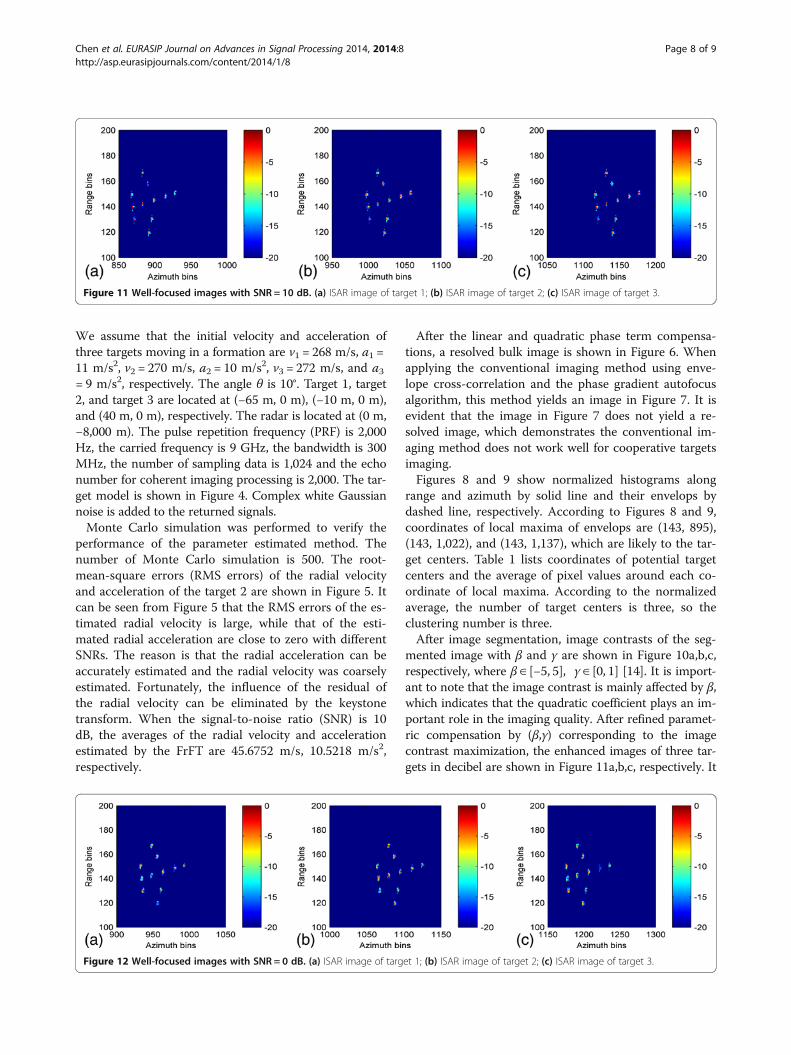
mented image with β and γ are shown in Figure 10a,b,c,respectively, where β ∈ [−5, 5], γ ∈ [0, 1] [14]. It is import-ant to note that the image contrast is mainly affected by β,which indicates that the quadratic coefficient plays an im-portant role in the imaging quality. After refined paramet-ric compensation by (β,γ) corresponding to the imagecontrast maximization, the enhanced images of three tar-gets in decibel are shown in Figure 11a,b,c, respectively. It
Figure 11 Well-focused images with SNR = 10 dB. (a) ISAR image of target 1; (b) ISAR image of target 2; (c) ISAR image of target 3.
Figure 12 Well-focused images with SNR = 0 dB. (a) ISAR image of target 1; (b) ISAR image of target 2; (c) ISAR image of target 3.
Chen et al. EURASIP Journal on Advances in Signal Processing 2014, 2014:8 Page 8 of 9http://asp.eurasipjournals.com/content/2014/1/8

is evident that each image has better focus than its originalimage in Figure 6.When the SNR is 0 dB, the averages of the radial vel-
ocity and acceleration estimated by the FrFT are 49.8649m/s, 10.3582 m/s2, respectively. The well-focused imagesof three targets in decibel are shown in Figure 12a,b,c,respectively. From this simulation, we believe that theproposed method can still image cooperative targets inthe low SNR scenario.
5. ConclusionsIn this paper, we have proposed a method to solve theradar imaging problem of cooperative targets. The methodutilizes the parametric compensation of the linear andquadratic phase terms to obtain a bulk image. Image seg-mentation is used to separate the bulk image into differentimages. Refined parametric compensation of the residualquadratic and cubic phase terms is then carried out to ob-tain well-focused images. The simulation results demon-strate that the proposed method can successfully imagecooperative targets.In future work, an experiment to generate well-focused
images of cooperative targets will be conducted based onmeasured data. Furthermore, our further study will focuson the imaging of cooperative targets that have morecomplicated motion forms.
Competing interestsThe authors declare that they have no competing interests.
AcknowledgementsThe authors are grateful to the anonymous reviewers for the providedfeedback. This work was supported by the National Natural ScienceFoundation of China under grant no. 61372159.
Received: 2 September 2013 Accepted: 18 January 2014Published: 24 January 2014
References1. Q Zhang, YQ Jin, Aspects of radar imaging using frequency-stepped chirp
signals. EURASIP J. Adv. Sig. Pr. 2006, 43–43 (2006)2. VC Chen, Q Shie, Joint time-frequency transform for radar range-Doppler
imaging. IEEE T Aero. Elec. Sys. 34, 486–499 (1998)3. L Zhang, JL Sheng, J Duan, MD Xing, Z-J Qiao, Z Bao, Translational motion
compensation for ISAR imaging under low SNR by minimum entropy.EURASIP J. Adv. Sig. Pr. 2013, 1–19 (2013)
4. CC Chen, CC Andrews, Target-motion-induced radar imaging. IEEE T Aero.Elec. Sys. 16, 1–14 (1980)
5. T Itoh, H Sueda, Y Watanabe, Motion compensation for ISAR via centroidtracking. IEEE T Aero. Elec. Sys. 32, 1191–1197 (1996)
6. J Li, R Wu, VC Chen, Robust autofocus algorithm for ISAR imaging ofmoving targets. IEEE T aero. Elec. Sys. 37, 1056–1069 (2001)
7. H Wu, D Grenier, GY Delisle, DG Fang, Translational motion compensationin ISAR image processing. IEEE Trans. Image Pr. 4, 1561–1571 (1995)
8. VC Chen, Time-frequency transforms for radar imaging and signal analysis(Artech House Radar Library, Boston, 2002)
9. VC Chen, ZZ Lu, Radar imaging of multiple moving targets, in Proceedings ofthe SPIE Radar Processing, Technology, and Application (San Diego, 1997).31 July–1 August
10. YN Li, YW Fu, X Li, L Le, L Wei, ISAR imaging of multiple targets usingparticle swarm optimisation-adaptive joint time frequency approach. IET Sig.Pr. 4, 343–351 (2010)
11. K Yamamoto, M Iwamoto, T Fujisaka, An ISAR imaging algorithm formultiple targets of different radial velocity. ELECTR Commun. JPN 86, 1–10(2003)
12. SH Park, KK Park, JH Jung, HT Kim, KT Kim, ISAR imaging of multiple targetsusing edge detection and Hough transform. J. Electromagnet. Wave.2, 365–373 (2008)
13. G Choi, S Park, H Kim, K Kim, ISAR imaging of multiple targets based onparticle swarm optimization and Hough transform. J. Electromagnet. Wave.23, 1825–1834 (2009)
14. SH Park, HT Kim, KT Kim, Segmentation of ISAR images of targets moving information. IEEE T Geosci. Remote. 48, 2099–2108 (2010)
15. XR Bai, F Zhou, MD Xing, Z Bao, A novel method for imaging of grouptargets moving in a formation. IEEE T Geosci. Remote. 50, 221–231 (2012)
16. E Sejdić, I Djurović, L Stanković, Fractional Fourier transform as a signalprocessing tool: an overview of recent developments. Sig Pr. 91, 1351–1369(2011)
17. RP Perry, RC DiPietro, RL Fante, SAR imaging of moving targets. IEEE T Aero.Elec. Sys. 35, 188–200 (1999)
18. G Franceschetti, J Tatoian, B Dutt, Aberrations in the SAR image of amoving target. Alta. Frequenza. 58, 175–183 (1989)
19. J Shi, J Malik, Normalized cuts and image segmentation. IEEE T Pattern Anal.22, 888–905 (2000)
20. M Martorella, F Berizzi, B Haywood, Contrast maximisation based techniquefor 2-D ISAR autofocusing. IET Sig. Pr. 152, 253–262 (2005)
doi:10.1186/1687-6180-2014-8Cite this article as: Chen et al.: Imaging targets moving in formationusing parametric compensation. EURASIP Journal on Advances in SignalProcessing 2014 2014:8.
Submit your manuscript to a journal and benefi t from:
7 Convenient online submission
7 Rigorous peer review
7 Immediate publication on acceptance
7 Open access: articles freely available online
7 High visibility within the fi eld
7 Retaining the copyright to your article
Submit your next manuscript at 7 springeropen.com
Chen et al. EURASIP Journal on Advances in Signal Processing 2014, 2014:8 Page 9 of 9http://asp.eurasipjournals.com/content/2014/1/8