iiiiiiiiiiiiiiiiiiiiiiiiiiiiiiiiiiiiiiiiiiiiiiiiiiiiiiiiii ....… ·...
TRANSCRIPT
IIIIIIIIIIIIIIIIIIIIIIIIIIIIIIIIIIIIIIIIIIIIIIIIIIIIIIIIIIIIIIIIIIIIIIIIIIIUS007142948B2
<12~ United States PatentMetz
(10) Patent No.: US 7,142,948 B2(45) Date of Patent: Nov. 28,2006
(54) CONTROLLER INTERFACE WITHDYNAMIC SCHEDULE DISPLAY
(75) Inventor: Stephen V. Metz, St. Paul, MN (US)
(73) Assignee: Honeywell International Inc.,Morristown, NJ (US)
( * ) Notice: Subject to any disclaimer, the term of thispatent is extended or adjusted under 35U.S.C. 154(b) by 168 days.
(21) Appl. Noz 10/753,917
(22) Filed: Jan. 7, 2004(Continued)
FOREIGN PATENT DOCUMENTS(65) Prior Publication Data
US 2005/0149233 Al JUI. 7, 20053334117.6 4/1985DE
(51) Int. Cl.GO5D 23IOOGO58 13IOO
(52) U.S. Cl......
(Continued)
OTHER PUBLICATIONS(2006.01)(2006.01)
700/276; 236/91 D; 236/94;700/52
(58) Field of Classification Search .................. 700/83,700/276, 17, 52; 236/91 R, 91 D, 94
See application file for complete search history.
Aprilaire Electronic Thermostats Models 8344, 8346, 8348, 8363,8365, 8366 Operating Instructions, 8 pages, prior to filing date ofpresent application.
(Continued)
Primary Examiner~harles R. Kasenge(56) References Cited
U.S. PATENT DOCUMENTS (57) ABSTRACT
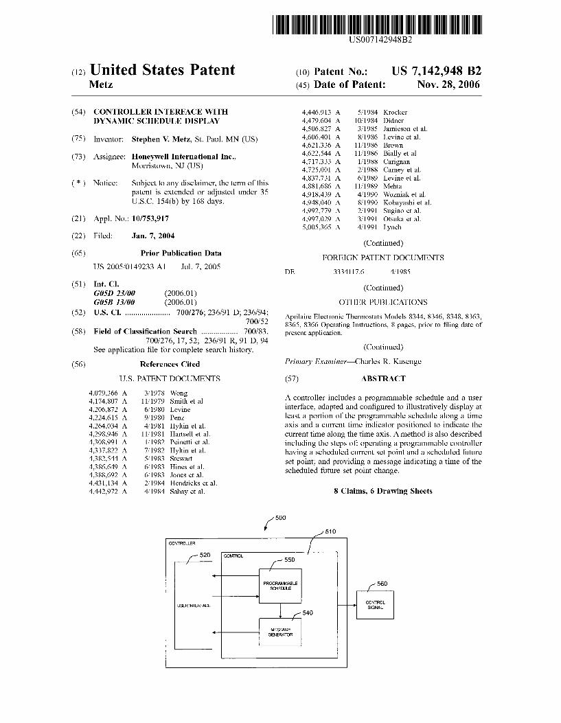
A controller includes a programmable schedule and a userinterface, adapted and configured to illustratively display atleast a portion of the programmable schedule along a timeaxis and a current time indicator positioned to indicate thecurrent time along the time axis. A method is also describedincluding the steps of: operating a programmable controllerhaving a scheduled current set point and a scheduled futureset point; and providing a message indicating a time of thescheduled future set point change.
S Claims, 6 Drawing Sheets
500
4,079,366 A4,174,807 A4,206,872 A4,224,615 A4,264,034 A4,298,946 A4,308,991 A4,337,822 A4,382,544 A4,386,649 A4,388,692 A4,431,134 A4,442,972 A
3/197811/19796/19809/19804/1981
11/1981I/19827/19825/19836/19836/19832/19844/1984
WongSmith et al.LevinePenzHyltin et al.Hartsell et al.Peinetti et al.Hyltin et al.StewartHines et al.Jones et al.Hendricks et al.Sahay et al.
4,446,913 A4,479,604 A4,506,827 A4,606,401 A4,621,336 A4,622,544 A4,717,333 A4,725,001 A4,837,731 A4,881,686 A4,918,439 A4,948,040 A4,992,779 A4,997,029 A5,005,365 A
5/198410/19843/19858/1986
11/198611/1986I/19 8 82/19 8 86/1989
11/19894/19908/19902/19913/19914/1991
KrockerDidnerJamieson et al.Levine et al.BrownBially et al.CarignanCarney et al.Levine et al.MehtaWozniak et al.Kobayashi et al.Sugino et al.Otsuka et al.Lynch
US 7,142,948 B2Page 2
U.S. PATENT DOCUMENTS... 236/91 R
3/20003/20003/20002/20017/20013/1997
10/199710/19977/2001
10/2001
EPEPEPEPEPWOWOWOWOWO
06782040985994
0985994010740091074009
WO 97/1144 gWO 97/3939
WO 97/39392WO 01/52515WO 01/79952
... 700/g3
OTHER PUBLICATIONS
5,012,9735,03g,g515,053,7525,065,8135,086,3855,0gg,6455,140,3105,161,6065,170,9355,181,6535,230,4825,23g, I g45,251,8135,259,4455,329,9915,348,07g5,386,5775,482,2095,526,4225,537,1065,566,8795,570,8375,673,8505,782,2965,g 1g,42g5,873,5195,gg6,6975,901,1835,902,1835,937,9425,947,3726,020,ggl6,032,8676,059,1956,081,1976,121,8756,140,9876,192,2826,196,4676,208,3316,236,3266,285,9126,290,1406,315,2116,318,6396,330,8066,344,8616,351,6936,39g, I lg6,478,2336,502,75g6,518,9576,578,7706,580,9506,5gl,g466,595,4306,619,5556,621,5076,786,421
2001/00295852001/00426842001/00524592002/00054352002/00927792003/00348972003/003489g2003/01216522003/01232242003/01421212003/01509262003/0150927
A A A A A A A A A A A A A A A A A A A A A A A A A A A A A A A A A A A A A BlBlBlBlBlBlBlBlBlBlBlBlBlBlBlBlBlBlBlBlBlBlAlAlAlAlAlAlAlAlAlAlAlAl
5/1991g/1991
10/199111/19912/19922/1992g/1992
11/199212/1992I/19937/1993g/1993
10/199311/19937/19949/1994I/1995I/19966/19967/1996
10/199611/199610/19977/199 g
10/199 g2/19993/19995/19995/1999g/19999/19992/20003/20005/20006/20009/2000
10/20002/20013/20013/20015/20019/20019/2001
11/200111/200112/20012/20022/20026/2002
11/2002I/20032/20036/20036/20036/20037/20039/20039/20039/2004
10/200111/200112/2001I/20027/20022/20032/20037/20037/20037/2003g/2003g/2003
Dick et al.MethaEpstein et al.Berkeley et al.Launey et al.......BellDeLuca et al.Berkeley et al.Federspiel et al.Foster et al.Ratz et al.AdamsKniepkampPratt et al.Metha et al.Dushane et al.ZendaCochran et al.KeenMitcuhashiLongtinBrown et al.Upte graphMethaEisenbrandt et al.BeilfussNaughton et al.D'SouzaD'SouzaBias et al.TiernanNaughton et al.Dushane et al.Adams et al.Garrick et al.Hamm et al.Stein et al.Smith et al.Dushane et al.Singh et al.MurphyEllison et al.Pesko et al.Sartain et al.TothBeaverson et al.Naughton et al.Monie et al.Rosen et al.ShahCottrellLehtinen et al.RosenJohnson et al.RosenShahRosenShahRosenSimon et al.Essalik et al.Essalik et al.CottrellEssalik et al.Shamoon et al.Shamoon et al.Carey et al.LaCroix et al.RosenRosenRosen
2004/007497g Al 4/2004 Rosen2004/0262410 Al* 12/2004 Hull .....
FOREIGN PATENT DOCUMENTS
Aube Technologies, Electronic Thermostat for Heating SystemModel TH135-01, 5 pages, Aug. 14, 2001.Aube Technologies, TH140-2g Electronic Thermostat, InstallationInstructions and User Guide, pp. 1-4, Jan. 22, 2004.Braeburn Model 3000 Owner's Manual, pp. 1-13, 2001.Braeburn Model 5000 Owner's Manual, pp. 1-17, 2001.BRK First Alert, User's Manual, Smoke and Fire Alarms, pp. 1-7,Nov. 2002.BRK Electronics Maximum Protection Plus Ultimate ConvenienceSmoke Alarm, 24 pages, prior to filing date of present application.Carrier Microelectronic Programmable Thermostat Owner'sManual, pp. 1-24, May 1994.Carrier TSTATCCRF01 Programmable Digital Thermostat, pp.1-21, prior to filing date of present application.Danfoss RT51/51RF & RT52/52RF User Instructions, 2 pages, Jun.2004.Firex Smoke Alarm, Ionization Models AD, ADC PhotoelectricModel Pad, 4 pages, prior to filing date of present application.Gentex Corporation, HD135, 135' Fixed Temperature Heat Detec-tor AC Pwered, 120V, 60Hz With Battery Backup, InstallationInstructions~wner's Information, pp. 1-5, Jun. I, 199g.Gentex Corporation, 9000 Series, Photoelectric Type Single Station/Multi-Station Smoke Alarms AC Powered With Battery Backup,Installation Instructions~wner's Information, pp. 9-1 to 9-6, Jan.I, 1993.Honeywell Brivis Deluxe Programmable Thermostat, pp. 1-20,2002.Honeywell Brivis Tg602C Chronotherm IV Deluxe ProgrammableThermostats, Installation Instructions, pp. 1-12, 2002.Honeywell CTg602C Professional Fuel Saver Thermostat, pp. 1-6,1995.Honeywell Electronic Programmable Thermostat, Owner's Guide,pp. 1-20, 2003.Honeywell Electric Programmable Thermostats, InstallationInstructions, pp. I-g, 2003.Honeywell Tg002 Programmable Thermostat, Installation Instruc-tions, pp. I-g, 2002.Honeywell Tg602A,B,C,D and TSg602A,C Chronotherm HI FuelSaver Thermostats, Installation Instructions, pp. 1-12, 1995.Honeywell Tg602D Chronotherm IV Deluxe Programmable Ther-mostats, Installation Instructions, pp. 1-12, 2002.Honeywell THg000 Series Programmable Thermostats, Owner'sGuide, pp. 1-44, 2004.Honeywell, MagicStat® CT3200 Programmable Thermostat,Installation and Programming Instructions, pp. 1-24, 2001.Invensys Deluxe Programmable Thermostats 9700, 9701, 9715,9720, User's Manual, 21 pages, prior to filing date of presentapplication.Lux TX9000 Installation, 3 pages, prior to filing date of presentapplication.Ritetemp Operation g029, 3 pages, Jun. 19, 2002.Ritetemp Operation g050, 5 pages, Jun. 26, 2002.Ritetemp Operation g085, pp. 1-6, prior to filing date of presentapplication.

US 7,142,948 B2Page 3
Sealed Unit Parts Co., Inc., Supco & CTC Thermostats... loadedwith features, designed for value!, 6 pages, prior to filing date ofpresent application.Totaline Model P474-1035 Owner's Manual Programmable 5-2Day Digital Thermostat, pp. 1-21, prior to filing date of presentapplication.Totaline Star CPE230RF, Commercial Programmable ThermostatWireless Transmitter, Owner's Manual, pp. 1-16, Oct. 1998.Totaline Star P/N P474-0130 Non-Programmable Digital Thermo-stat Owner's Manual, pp. 1-22, prior to filing date of presentapplication.White-Rogers IF SO-224 Programmable Electronic Digital Thermo-stat, Installation and Operation Instructions, g pages, prior to filingdate of present application.White-Rodgers Installation Instructions for Heating & Air Condi-tioning IF7g Non-Programmable Thermostat, 6 pages, prior to filingof present application.White-Rodgers, Comfort-Set 90 Series Premium, 4 pages, prior tofiling date of present application.ADI, "Leopard User Manual," 93 pages, 2001.Adicon 2500, "The Automator," 4 pages, Oct.-Dec. 2000.ADT Security Service, "iCenter Advanced User Interface8 142ADT," Installation and Setup Guide, 5 pages, May 2001; FirstSale Feb. 2001.Business Wire, "MicroTouch Specialty Products Group to Capital-ize on Growing Market for Low-Cost Digital Matrix Touchscreens,"p. 1174 (2 pages), Jan. 6, 1999.Climatouch, User Manual, Climatouch CT03TSB Thermostat,Climatouch CT03TSHB Thermostat with Humidity Control, Out-door UHF Temperature Transmitter 217S31, 19 pages, Printed Sep.15, 2004.DeKoven et al., "Designing Collaboration in Consumer Products,"2 pages, 2001.Freudenthal et al., "Communicating extensive smart home func-tionality to users of all ages: the design of a mixed-initiativemultidodal thermostat-interface," pp. 34-39, Mar. 12-13, 2001.Honeywell News Release, "Honeywell's New Sysnet FacilitiesIntegration System For Boiler Plant and Combustion Safety Pro-cesses," 4 pages, Dec. 15, 1995.Honeywell, "Introduction of the S7350A Honeywell WebPADInformation Appliance," Home and Building Control Bulletin, 2pages, Aug. 29, 2000; Picture of WebPad Device with touch screen,I Page; and screen shots of WebPad Device, 4 pages.Honeywell, "W7006A Home Controller Gateway User Guide," 31pages, Jul. 2001."Mark of Excellence Award Finalist Announced," http://64. 233. 167.104/search? Q=cache: ciOA2YtYaBI I; www hometoys.corn/re-leased/mar..., 6 pages, Leopard Touchscreen on page 2, datedprior to Mar. 4, 2000, printed Aug. 20, 2004."High-tech options take hold in new homes 200-08-2g DallasBusiness Journal," http;//bizjournals.corn/dallas/stories/2000/Og/2g/focus4, 3 pages, dated Aug. 2g, 2000, printed Aug. 19, 2004."Product Review Philips Pronto Remote Control," http: //hometheaterhifi.corn/volume 6 2/philipsprontoremotecontrol.html, 5 pages, dated May 1999, printed Aug. 20, 2004."CorAccess Systems/In Home," http: //web.archive.org/web20011212084427/www.coraccess.corn/home. html, I page,copyright 2001, printed Aug. 19, 2004."A Full Range of Alternative User Interfaces For Building Occu-pants and Operators," http: //www.automatedbuildings.corn/news/jan00/articles/andover/andover.htm, 5 pages, dated Jan. 2000,printed Sep. 20, 2004.http;//www.cc.gatech.edu/computing/classes/cs6751 94 fall/groupc/climate-2/nodel.html, "Contents," 53 pages, printed Sep.20, 2004."HAI Company Background," http: //www.homeauto.corn/AboutHAI/abouthai main.htm, 2 pages, printed Aug. 19, 2004.Cardio, by Secant; http;//www.hometoys.corn/htinews/apr9g/re-views/cardio.htm, "HTINews Review," Feb. 1998, 5 pages, printedSep. 14, 2004.Cardio Manual, available at http: //www.secant.ca/En/Documenta-tion/Cardio2e-Manual.pdf, Cardio Home Automation Inc., 55pages, printed Sep. 2g, 2004.
Domotique Secant Home Automation Web Page, available athttp: //www.secant.ca/En/Company/Default.asp, I page, printedSep. 2g, 2004."Vantage Expands Controls For Audio&ideo, HVAC and Security,"http: //www.hometoys.corn/htinews/aug99/releases/vantage03.htm,2 pages, dated Aug. 3, 1999, printed Aug. 20, 2004.Visor Handheld User Guide, Copyright 1999-2000."Home Toys Review TouchLinc", http: //www.hometoys.corn/htinews/aug99/reviews/touchlinc/touchlinc.htm, 3 pages, datedAug. 1999, printed Aug. 20, 2004."RC X10 Automation Forum: Control your Heating and CoolingSystem with Pronto(1/1)," http;//www.remotecentral.corn/cgi-bin/mboard/rc-x 10/thread.cgi? 12, 2 pages, dated Apr. 23, 1999, printedAug. 20, 2004.Blake et al., "Seng 310 Final Project" Report, dated Apr. 6, 2001.Blake et al., "Seng 310 Final Project Demo Program" Illustration,3 pages, Apr. 6, 2001."Spotlight on integrated systems," Custom Builder, Vg, N2, p.66(6), Mar.-Apr. 1993.AutomatedBuildings.corn Article "Thin Client" Solutions, "Pres-sure, Air Flow, Temperature, Humidity & Valves," Dwyer Instru-ments, Inc., 5 pages, printed Sep. 20, 2004.ADT Security Services, "iCenter Advanced User Interface8 142ADT," Installation and Setup Guide, 5 pages, May 2001; FirstSale Feb. 2001.Cardio, by Secant; http;//www.hometoys.corn/htinews/apr9g/re-views/cardio.htm, "HTINews Review," Feb. 1998, 5 pages, printedSep. 14, 2004.Carrier, "Programmable Dual Fuel Thermostat," Installation, Start-Up & Operating Instructions, pp. 1-12, Oct. 1998.Carrier, "Programmable Thermostats," Installation, Start-Up &Operating Instructions, pp. 1-16, Sep. 1998.Carrier, "Standard Programmable Thermostat," Homeowner'sManual, pp. I-g pages, 1998.Carrier, "Thermidistat Control," Installation, Start-Up, and Operat-ing Instructions, pp. 1-12, Aug. 1999.CorAccess, "Companion 6," User Guide, pp. 1-20, Jun. 17, 2002.http:/.www.ritetemp.info/rtMenu 13.html, Rite Temp 8082, gpages, printed Jun. 20, 2003.http;//www.thermo statsales.corn, Robertshaw, "9610 DigitalProgammable Thermostat," 3 pages, printed Jun. 17, 2004.http: //www.thermostatsales.corn, Robertshaw, "9700 Deluxe Pro-grammable Thermostat" 3 pages, printed Jun. 17, 2004.http: //www.thermostatsales.corn, Robertshaw, "9710 Deluxe Pro-grammable Thermostat," 3 pages, printed Jun. 17, 2004.http: //www.thermostatsales.corn, Robertshaw, "9720 Deluxe Pro-grammable Thermostat," 3 pages, printed Jun. 17, 2004.Hunter, "44200/44250," Owner's Manual, 32 pages, printed prior tofiling date.Hunter, "44300/44350," Owner's Manual, 35 pages, printed prior tofiling date.Hunter, "Auto Saver 550", Owner's Manual Model 44550, 44pages, printed prior to filing date.Invensysâ„¢, "9700i 9701i 9715i 9720i Deluxe ProgrammableThermostats," User's Manual, pp. 1-2g, printed prior to filing date.Lux, "ELVI Programmable Line Voltage Thermostat," Owner'sManual, 3 pages, printed prior to filing date.Lux, "511 Series Smart Temp Electronic Thermostat," Owner'sManual, 3 pages, printed prior to filing date.Lux, "600 Series Smart Temp Electronic Thermostat," Owner'sManual, 3 pages, printed prior to filing date.Lux, "602 Series Multi-Stage Programmable Thermostat," Owner'sManual, 2 pages, printed prior to filing date.Lux, "605/2110 Series Programmable Heat Pump Thermostat,"Owner's Manual, 3 pages, printed prior to filing date.Lux, "700/9000 Series Smart Temp Electronic Thermostat," Own-er's Manual, 3 pages, printed prior to filing date.Lux, "PSPH521 Series Programmable Heat Pump Thermostat,"Owner's Manual, 3 pages, printed prior to filing date.Lux, "TX1500 Series Smart Temp Electronic Thermostat," Owner'sManual, 6 pages, printed prior to filing date.Lux, "TX500 Series Smart Temp Electronic Thermostat," Owner'sManual, 3 pages, printed prior to filing date.
US 7,142,948 B2Page 4
METASYS, "HVAC Pro for Windows User's Manual," 308 pages,1998.Totaline, "I For All programmable Digital Thermostat," Owner'sManual P/N P374-1100FM, 23 pages, Nov. 1998.Totaline, "I For All Programmable Digital Thermostat," Owner'sManual P/N P474-1050, 21 pages, Nov. 1998.Totaline, "I For All Programmable Digital Thermostat," Owner'sManual P/N P374-1100, 24 pages, Apr. 2001.Totaline, "Intellistat Combination Temperature and Humidity Con-trol," Owner's Manual P/N P374-1600, 25 pages, Jun. 2001.Totaline, "Programmable Thermostat Configurable for AdvancedHeat Pump or Dual Fuel Operation," Owner's Manual P/N P374-1500, 24 pages, Jun. 1999.Totaline, "Instructions P/N P474-1010", Manual, 2 pages, Dec.1998.Totaline, "Programmable Thermostat", Homeowner's Guide, 27pages, Dec. 1998.Totaline, "Wireless Programmable Digital Thermostat," Owner'sManual 474-1100RF, 21 pages, 2000.Warmly Yours, "Model THIIIGFCI-P (120 VACi," Manual, pp.1-4, printed prior to filing date.White-Rogers, "Installation Instructions for Heating & Air Condi-tioning IF72 5/2 Day Programmable Heat Pump Thermostat," gpages, printed prior to filing date.White-Rodgers, "Installation Instructions for Heating & Air Con-ditioning IF7g 5/2 Day Programmable Thermostat," 7 pages,printed prior to filing date.White-Rodgers, "Comfort-Set 90 Series Thermostat," Manual, pp.1-24, printed prior to filing date.White-Rodgers, "Comfort-Set HI Thermostat," Manual, pp. 1-44,printed prior to filing date.White-Rodgers, IFSO-240 "(for Heating Only systems) Program-mable Electronic Digital Thermostat," Installation and OperationInstructions, g pages, printed prior to filing date.White-Rodgers, IF SO-241 "Programmable Electronic Digital Ther-mostat," Installation and Operation Instructions, 6 pages, printedprior to filing date.White-Rodgers, IF SO-261 "Programmable Electronic Digital Ther-mostat," Installation and Operation Instructions, g pages, printedprior to filing date.White-Rodgers, I F8 1-261 "Programmable Electronic DigitalMulti-Stage Thermostat," Installation and Operation Instructions, gpages, printed prior to filing date.
White-Rodgers, IFS2-261 "Programmable Electronic Digital HeatPump Thermostat," Installation and Operation Instructions, g pages,printed prior to filing date.
www.icmcontrols.corn, Simplecomfort, SC3000 Single State Heat/Single Stage Cool or Single Stage Heat Pump/Manual Changeover,I page, printed prior to filing date.
www.icmcontrols.corn, Simplecomfort, SC3001 Single Stage Heat/Single Stage Cool or Single Stage Heat Pump/Manual Changeover,I page, printed prior to filing date.www.icmcontrols.corn, Simplecomfort, SC3006 Single Stage Heat/Single Stage Cool or Single Stage Heat Pump/Manual Changeover,I page, printed prior to filing date.www.icmcontrols.corn, Simplecomfort, SC3201 2 Stage Heat PumpManual Changeover, I page, printed prior to filing date.www.icmcontrols.corn, Simplecomfort, SC3801 2 Stage Heat/2Stage Cool 2 Stage Heat Pump/Audio Changeover, I page, printedprior to filing date.Prolifix Inc., "Web Enabled IP Thermo stats," 2 pages, prior to filingdate of present application.ADT Security Systems, "iCenter Advanced User InterfacegI42ADT User Guide," pp. 1-136, 2001.
DeKoven et al., "Measuring Task Models in Designing IntelligentProducts," pp. I gg-1 89, 2002.
http;//www.hometoys.corn/htinews/apr99/releases/ha101.htm, HTINews Release, pp. 1-3, printed Oct. 2g, 2004.U.S. Appl. No. 10/440,474, filed May IS, 2003, entitled "ReverseImages in a Dot Matrix LCD for an Environmental ControlDevice.".
U.S. Appl. No. IO/654,230, filed Sep. 3, 2003, entitled "Program-mable Thermostat Incorporating a Liquid Crystal Display andHaving a Feature for Mounting Horizontally, Vertically and anyIntermediate Orientation".
U.S. Appl. No. IO/654/235, filed Sep. 3, 2003, entitled "Program-mable Thermostat Incorporating a Liquid Crystal Display Selec-tively Presenting Adaptable System Menus Including ChangeableInteractive Vitual Buttons.".
* cited by examiner

U.S. Patent Nov. 28, 2006 Sheet 1 of 6
100
F ig.l
US 7,142,948 B2

U.S. Patent Nov. 28, 2006 Sheet 2 of 6
Fig.2
US 7,142,948 B2
200
U.S. Patent Nov. 28, 2006 Sheet 3 of 6
Fig.3
US 7,142,948 B2
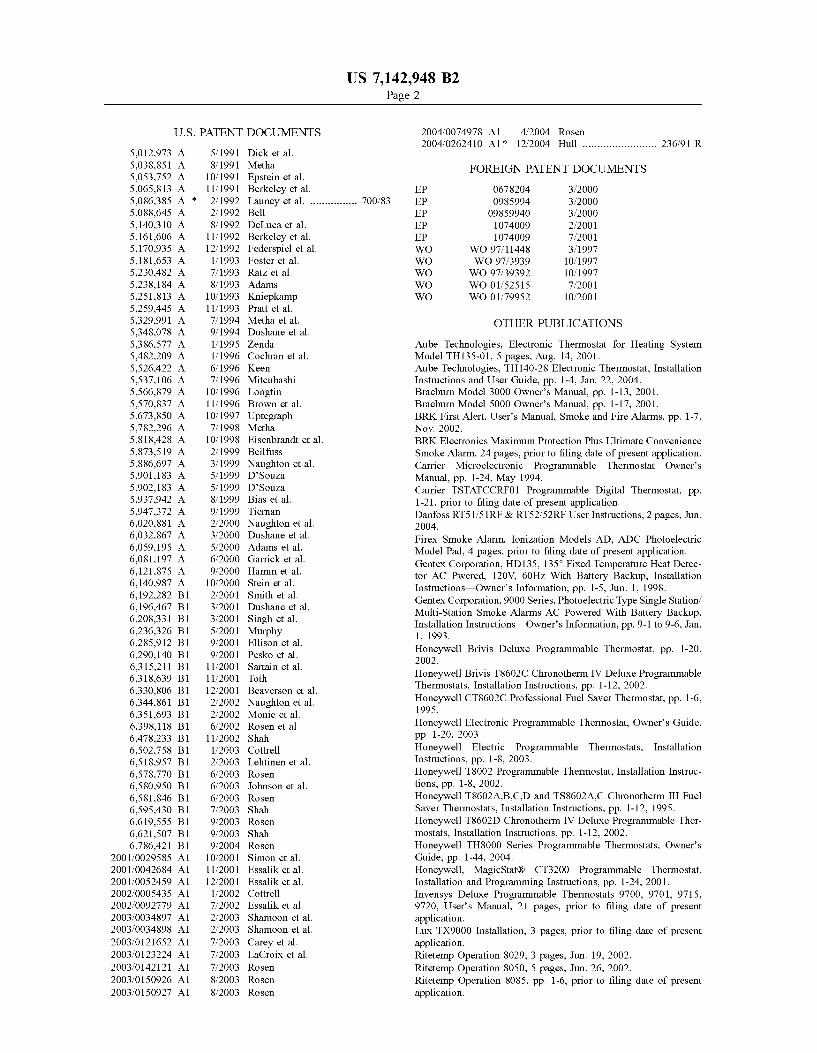
300
U.S. Patent Nov. 28, 2006
Sta~
Sheet 4 of 6 US 7,142,948 B2
400
450

U.S. Patent Nov. 28, 2006 Sheet 5 of 6
500
F ig.5
US 7,142,948 B2

U.S. Patent Nov. 28, 2006 Sheet 6 of 6
Fig.6
US 7,142,948 B2
600
US 7,142,948 B2
10
65
1CONTROLLER INTERFACE WITH
DYNAMIC SCHEDULE DISPLAY
FIELD OF THE INVENTION
The present invention relates generally to the field ofprogrammable controllers for devices. More specifically, thepresent invention pertains to simplified interfaces for devicecontrollers having a dynamic schedule display.
BACKGROUND OF THE INVENTION
Controllers are used on a wide variety of devices andsystems. Some controllers have schedule programming thatmodifies schedule parameters such as set points as a functionof date and/or time. Some device or system controllers thatutilize schedule programming include, for example, HVACcontrollers, security system controllers, lawn sprinkler con-trollers, and lighting system controllers.
In one example, HVAC controllers are often employed inmonitoring and, if necessary, controlling various environ-mental conditions within a home, office or other enclosedspace. Such devices are useful, for example, in regulatingthe temperature, humidity, venting, air quality, etc., within aparticular space. The controller may include a microproces-sor that interacts with other components in the HVACsystem. For example, in many modem thermostats for use inthe home or office setting, a controller unit may be providedto interact with a heater, blower, flue vent, air compressor,humidifier and/or other components, to control the tempera-ture, humidity or other environmental conditions at variouslocations within the home or office. One or more sensorslocated within the controller unit and/or one or more remotesensors may be employed to sense when the temperatureand/or humidity (or other environmental conditions) reachesa certain threshold level, causing the controller unit to senda signal to activate or deactivate one or more component inthe system.
The controller may be equipped with an interface thatallows the user to monitor and adjust the environmentalconditions at one or more locations within the building. Withmore modem designs, the interface typically includes aliquid crystal display (LCD) panel inset within a housingthat contains a microprocessor as well as other componentsof the controller. In some designs, the interface may permitthe user to program the controller to activate on a certainschedule determined by the user. For example, the interfacemay include a menu routine that permits the user to changethe temperature at one or more times during a particular day.Once the settings for that day have been programmed, theuser can repeat the process to change the settings for theother remaining days.
In some cases, the interface is simply too complex orcumbersome to be conveniently used to inform the user ofwhere the schedule is in relation to the current time and issimply by-passed or programmed by the user to a tempera-ture set point beyond the desired value in an attempt toachieve a desired temperature quickly. Accordingly, there isan ongoing need in the art to improve the ease of use andunderstanding of the current schedule in a programmablecontroller.
SUMMARY OF THE INVENTION
Generally, the present invention pertains to simplifiedinterfaces for controllers having a dynamic schedule display.
15
20
25
30
35
40
45
50
55
60
In one illustrative embodiment, a controller includes aprogrammable schedule and a user interface, adapted andconfigured to illustratively display at least a portion of theprogrammable schedule along a time axis and a current timeindicator positioned to indicate the current time along thetime axis.
In a further illustrative embodiment, a method isdescribed including the steps of: operating a programmablecontroller having a scheduled current set point and a sched-uled future set point; and providing a message indicating atime of the scheduled future set point change.
In another illustrative embodiment, a method includes thesteps of: operating a programmable controller to cause anHVAC system to change an environmental condition of aninside space from a first initial set point to a second desiredset point, the HVAC system achieving the change in theenvironmental condition to the second desired set point in anamount of time; and providing a message during the amountof time indicating when the desired second set point isanticipated to be achieved in the inside space.
In another illustrative embodiment, a method includes thesteps of: operating a programmable controller to cause anHVAC system to change an environmental condition of aninside space from a first initial set point to a second desiredset point, the HVAC system achieving the change in theenvironmental condition to the second desired set point in anamount of time; allowing a user to change the second desiredset point to a third over-controlling set point; and informingthe user that changing the second desired set point to thethird over-controlling set point will not decrease the amountof time needed to achieve the second desired set point.Controllers adapted to provide the above methods are alsocontemplated.
The above summary of the present invention is notintended to describe each disclosed embodiment or everyimplementation of the present invention. The Figures,Detailed Description and Examples which follow moreparticularly exemplify these embodiments.
BRIEF DESCRIPTION OF THE DRAWINGS
The invention may be more completely understood inconsideration of the following detailed description of vari-ous embodiments of the invention in connection with theaccompanying drawings, in which:
FIG. I is a block diagram of an illustrative controller;
FIG. 2 is a schematic drawing of an illustrative userinterface in accordance with the present invention;
FIG. 3 is a schematic drawing of another illustrative userinterface in accordance with the present invention;
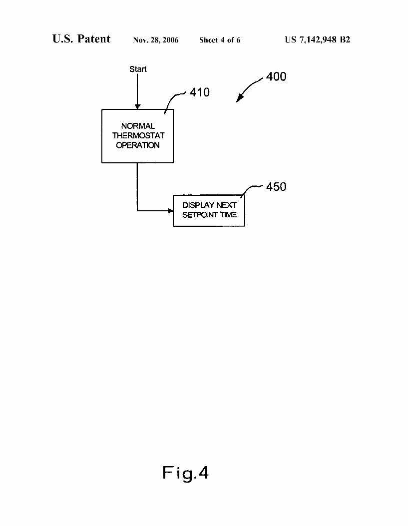
FIG. 4 is a flow diagram of an illustrative controllerprogram;
FIG. 5 is a block diagram of the illustrative controllerprogram shown in FIG. 4; and
FIG. 6 is a schematic drawing of another illustrative userinterface in accordance with the present invention.
While the invention is amenable to various modificationsand alternative forms, specifics thereof have been shown byway of example in the drawings and will be described indetail. It should be understood, however, that the intention isnot to limit the invention to the particular embodimentsdescribed. On the contrary, the intention is to cover allmodifications, equivalents, and alternatives falling withinthe spirit and scope of the invention.
US 7,142,948 B2
3DETAILED DESCRIPTION OF THE
INVENTION
The following description should be read with referenceto the drawings, in which like elements in difierent drawingsare numbered in like fashion. The drawings, which are notnecessarily to scale, depict selected embodiments and arenot intended to limit the scope of the invention. Althoughexamples of construction, dimensions, and materials areillustrated for the various elements, those skilled in the artwill recognize that many of the examples provided havesuitable alternatives that may be utilized.
Generally, the present invention pertains to simplifiedinterfaces for controllers having schedule override program-ming capabilities. These controllers can be used in a varietyof systems such as, for example, HVAC systems, sprinklersystems, security systems, lighting systems, and the like.The Figures depict illustrative HVAC controllers. While thepresent invention is not so limited, an appreciation ofvarious aspects of the invention will be gained through adiscussion of the examples provided below.
HVAC controllers can regulate environmental conditionssuch as, for example, temperature within an enclosed space.The controller can regulate the environmental condition as afunction of time by using, for example, a programmableschedule. That is, the programmed schedule may cause thecontroller to activate one or more components of an HVACsystem such that the desired environmental condition fol-lows the programmed schedule.
In some cases, a user interface may include a separatemenu routine that builds and/or modifies a schedule topermit the user to change the temperature at one or moretimes during a particular day such as, for example, atemperature setting for a "wake" time interval, a "leave"time interval, a "return" time interval and/or a "sleep" timeinterval. The user can program a start time and/or end time(and/or time duration) for each and a heat and/or cooltemperature for each desired time interval. Once the settingsfor that day have been programmed, the user can oftenrepeat the process to change the settings for the otherremaining days of the week with the schedule. In somecases, the programmable controller may include a featurethat allows the user to set a separate schedule for weekdayand weekend use, and/or to copy the settings from a par-ticular day to another day, as desired. Other methods forprogramming the schedule are also contemplated.
FIG. 1 is a block diagram of an illustrative controller 100.Controller 100 includes a control module 110 that can be amicroprocessor or the like. The control module 110 caninclude a programmable schedule 250 as described above,for example. The control module 110 communicates with auser interface 120. The control module can also generate oneor more control signals 260 to a device (not shown), such asan HVAC system or device.
In the illustrative embodiment, the user interface 120 isadapted and configured to display at least a portion of theprogrammable schedule 150 along a time axis. A currenttime indicator can be positioned to indicate the current timein relation to the time axis, and thus the schedule. Thecurrent time indicator may allow a user to easily identify thecurrent schedule setting, the duration of the current schedulesetting, the prior schedule setting and/or the next schedulesetting, for example.
FIG. 2 is a schematic drawing of an illustrative userinterface 200. The user interface 200 can illustrativelydisplay at least a portion of the programmable schedule 225along a time axis 22S. A current time indicator 224 can be
5
10
15
20
25
30
35
40
45
50
55
60
65
positioned to indicate the current time in relation to the timeaxis 22S, and thus the schedule. This embodiment illustratesa current time indicator 224 superimposed on the time axis22S, however, this is not required in all embodiments.
This embodiment also illustrates a programmable sched-ule 225 displayed as a block bar graph. The block bar graphcan display the programmable schedule 225 as a block barbroken into segments 229 and 230. The segments 229 and230 can represent difi'erent schedule set points. The seg-ments 229 and 230 can be graphically contrasting such asfirst segment 229 may be a lighter color or shade than thesecond segment 330, for example. Alternatively or in addi-tion, each segment 229 and 230 can display a numerical ortextual message 226 and/or 227, informing the user of thename of the block bar segment 229 and 230 or a particularnumerical value associated with the block bar segment 229and 230. For example, block bar segment 229 message 226could display "Wake," "68"' or "Wake-68"' and block barsegment 230 message 227 could display "Leave," "72"', or"Leave-72'."
In some cases, any portion of the programmable schedule225 may be displayed on the user interface 200. Theillustrative embodiment of FIG. 2 shows an approximate 4hour time window, however any length of time can bedisplayed such as, for example, 24 hour or more, 12 hour, 8hour, 4 hour, 2 hour or less, as desired. The programmableschedule 225 may move or scroll in relation to the currenttime indicator 224. Alternatively, the current time indicator224 may move or scroll in relation to the programmableschedule 225.
Additional information may be displayed on the userinterface 200 at, for example block 215. This additionalinformation may include a current scheduled parametersetting (e.g., temperature, humidity), a current parameterreading, and/or any other information as desired.
FIG. 3 is another illustrative user interface 300 in accor-dance with the present invention. Like above, the userinterface 300 can illustratively display at least a portion ofthe programmable schedule 325 along a time axis 32S. Acurrent time indicator 324 can be positioned to indicate thecurrent time in relation to the time axis 32S, and thus theschedule. This embodiment illustrates a current time indi-cator 324 positioned below the time axis 22S and a currenttime indicator 324 above the programmable schedule 325.
This embodiment also illustrates a programmable sched-ule 325 displayed as a line graph. The line graph can displaythe programmable schedule 325 as step segments 329 and330. The segments 329 and 330 can represent difierentschedule set points. The step segments 329 and 330 can begraphically contrasting such as first line segment 329 may bea lighter color or shade than the second line segment 330, forexample. Alternatively or in addition, each segment 329 and330 can display a numerical or textual message 326 and/or327, informing the user of the name of the step segment 329and 330 or a particular numerical value associated with thestep segment 329 and 330. For example, step segment 229message 226 may display "Wake," "68"', or "Wake-68"'and step segment 230 message 227 could display "Leave,""72"', or "Leave-72'."
In some cases, any portion of the programmable schedule325 may be displayed on the user interface 300. Theillustrative embodiment shows an approximate 4 hour timewindow, however any length of time can be displayed suchas, for example, 24 hour or more, 12 hour, 8 hour, 4 hour, 2hour or less. The programmable schedule 325 may move orscroll in relation to the current time indicator 324. Alterna-

US 7,142,948 B2
tively, the current time indicator 324 may move or scroll inrelation to the programmable schedule 325.
Additional information could be displayed on the userinterface 300 at, for example block 315. This additionalinformation may include a current scheduled parametersetting (e.g., temperature, humidity), a current parameterreading, and/or other information as desired.
FIG. 4 is a flow diagram of an illustrative controllerprogram 400. The program starts at a normal thermostatoperation block 410, although this is not required in allembodiments. In the illustrative embodiment, when operat-ing in normal thermostat operation block 410, a pro-grammed thermostat schedule may be followed to regulateone or more environmental conditions of an inside space.The programmed schedule can activate the controller to sendone or more control signals to HVAC equipment on a certainschedule having at least a current set point and a future setpoint, as described above.
In the illustrative embodiment, a message 450 is providedvia the user interface indicating a time of a scheduled nextfuture set point change. The message 450 can be graphical,textual, aural or any other suitable message. The message450 may provide a time of day and/or duration of time untilthe controller changes set points or the inside space envi-ronmental condition changes to the desired set point. Alter-natively or in addition, the message 450 may provided aname or title of the current and/or next set point interval,such as, for example, "Wake," "Leave," "Return," and/or"Sleep", as described above. Alternatively or in addition, themessage 450 may provide the next set point value and/or thatthe inside room environmental condition will be increasingor decreasing to a desired next set point such as displayingthat the inside space will be cooling or heating to a desiredset point in a predicted or anticipated amount of time.
The message 450 may be displayed continuously, or at apredetermined time before a next scheduled future set pointchange occurs. For example, the message 450 can be dis-played 12 hours, 8 hours, 4 hours, 2 hours, I hour, 30minutes or less before a next scheduled future set pointchange occurs. The message 450 may also be displayedduring an amount of time that an inside space is rampingfrom a first set point to a next scheduled set point.
In some cases, a user may try to over-control the control-ler by entering an over-controlling set point in an attempt toincrease the rate of temperature change and/or decrease theamount of time required to change the temperature in aninside space. However, if the HVAC device is a simpleon/ofl' device, as is typically the case, the over-controllingset point does not aflect the rate of temperature change froma first set point to a desired second set point. Thus, themessage 450 can be adapted to inform the user that enteringan over-controlling set point will not increase the rate oftemperature change and/or decrease the amount of timerequired to change the temperature of the inside space. Insome embodiments, the message 450 can continue to informthe user of the time and/or duration of time until the insidespace reaches the next scheduled set point value, even if theuser modifies the current temperature setting.
FIG. 5 is a block diagram of the illustrative controllerprogram shown in FIG. 4. In the illustrative embodiment, acontroller 500 includes a control module 510 than can be amicroprocessor or the like. The control module 510 caninclude a programmable schedule 550 as described above,for example. The control module 510 communicates with auser interface 520 and a message generator 540. The controlmodule can also generate one or more control signals 560 toa device (not shown), such as an HVAC system or device.
5
10
15
20
25
30
35
40
45
50
55
60
65
The message generator 540 provides a message to the userinterface 520 indicating when the next set point is scheduledto occur, as described above.
FIG. 6 is a schematic drawing of an illustrative userinterface 600 in accordance with the present invention. Inthe illustrative embodiment, the user interface 600 candisplay a message at block 635 on the user interface 600indicating when the next set point change is scheduled tooccur, as described above. For example, the message dis-played at block 635 can be "Cooling in 10 min," "65' F. in10 min," "Cooling to 65' F. in 10 min," "Heating in 5 min""70' in 5 min," "Heating to 70' in 5 min," and the like.
Additional information could be displayed on the userinterface 600 at, for example block 615. This additionalinformation may include a current scheduled parametersetting (e.g., temperature, humidity), a current parameterreading, and/or other information as desired.
The present invention should not be considered limited tothe particular examples described above, but rather shouldbe understood to cover all aspects of the invention as fairlyset out in the attached claims. Various modifications, equiva-lent processes, as well as numerous structures to which thepresent invention can be applicable will be readily apparentto those of skill in the art to which the present invention isdirected upon review of the instant specification.
What is claimed is:1. A method comprising the steps of:operating a programmable controller to cause an HVAC
system to change an environmental condition of aninside space from a first initial set point to a seconddesired set point, the HVAC system achieving thechange in the environmental condition to the seconddesired set point in an amount of time; and
providing a message during the amount of time indicatingwhen the desired second set point is anticipated to beachieved in the inside space.
2. The method according to claim 1, further comprisingentering a third over-controlling set point and still providinga message during the amount of time indicating when thedesired second set point is anticipated to be achieved in theinside space.
3. The method according to claim 1, wherein the provid-ing a message comprises providing a message of a durationof time until the desired second set point is anticipated to beachieved in the inside space.
4. The method according to claim 1, wherein the provid-ing a message comprises providing a message of a time ofday when the desired second set point is anticipated to beachieved in the inside space.
5. The method according to claim 1, wherein the provid-ing a message comprises providing a message of when thedesired second set point is anticipated to be achieved in theinside space and what the desired second set point is.
6. A controller comprising:a programmable controller arranged and configured to
cause an HVAC system to change an environmentalcondition of an inside space from a first initial set pointto a second desired set point, the HVAC system achiev-ing the change in the environmental condition to thesecond desired set point in an amount of time; and
a message displayed during the amount of time indicatingwhen the desired second set point is anticipated to beachieved in the inside space.
7. A method comprising the steps of:operating a programmable controller to cause an HVAC
system to change an environmental condition of aninside space from a first initial set point to a second
US 7,142,948 B2
desired set point, the HVAC system achieving thechange in the environmental condition to the seconddesired set point in an amount of time;
allowing a user to change the set point to a third over-controlling set point during the amount of time; and 5
informing the user that changing the set point to the thirdover-controlling set point will not decrease the amountof time needed to achieve the second desired set point.
S. A method comprising the steps of:operating a programmable controller to cause an HVAC to
system to change an environmental condition of an
inside space from a first initial set point to a seconddesired set point; and
selectively displaying a message when the HVAC systemis attempting to change the environmental condition ofan inside space from the first initial set point to thesecond desired set point, the message indicating whenthe second desired set point is anticipated to beachieved in the inside space.