ii year b. tech i- semester mechanical engineering
TRANSCRIPT

MALLA REDDY COLLEGE OF ENGINEERING & TECHNOLOGY
DEPARTMENT OF MECHANICAL ENGINEERING (Autonomous Institution-UGC, Govt. of India) Secunderabad-500100,Telangana State, India.
www.mrcet.ac.in
II Year B. Tech I- Semester
MECHANICAL ENGINEERING
QUESTION BANK
ENGINEERING MECHANICS
www.mrcet.ac.in
MALLA REDDY COLLEGE OF ENGINEERING & TECHNOLOGY (Autonomous Institution – UGC, Govt. of India)
DEPARTMENT OF MECHANICAL ENGINEERING
EM QUESTION BANK
UNIT-1:
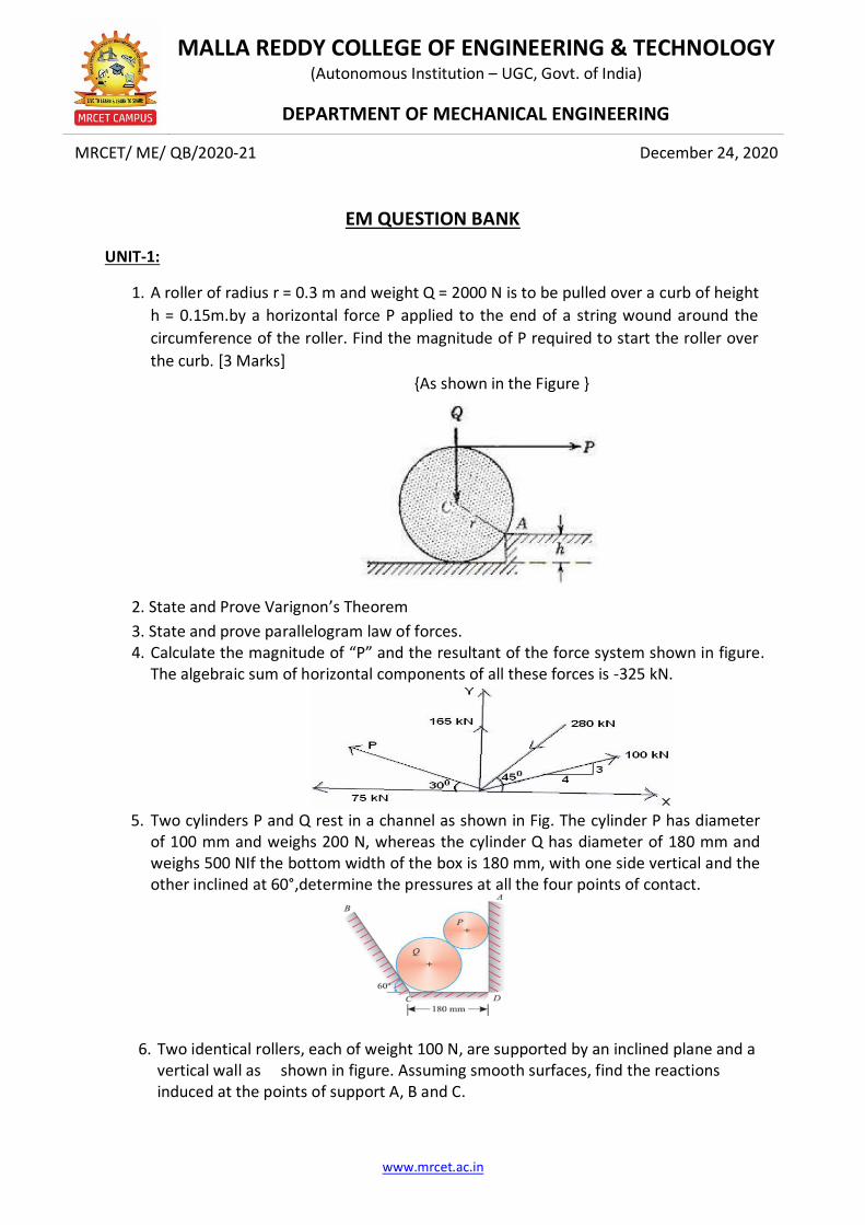
1. A roller of radius r = 0.3 m and weight Q = 2000 N is to be pulled over a curb of height
h = 0.15m.by a horizontal force P applied to the end of a string wound around the
circumference of the roller. Find the magnitude of P required to start the roller over
the curb. [3 Marks]
{As shown in the Figure }
2. State and Prove Varignon’s Theorem
3. State and prove parallelogram law of forces. 4. Calculate the magnitude of “P” and the resultant of the force system shown in figure.
The algebraic sum of horizontal components of all these forces is -325 kN.
5. Two cylinders P and Q rest in a channel as shown in Fig. The cylinder P has diameter
of 100 mm and weighs 200 N, whereas the cylinder Q has diameter of 180 mm and weighs 500 NIf the bottom width of the box is 180 mm, with one side vertical and the other inclined at 60°,determine the pressures at all the four points of contact.
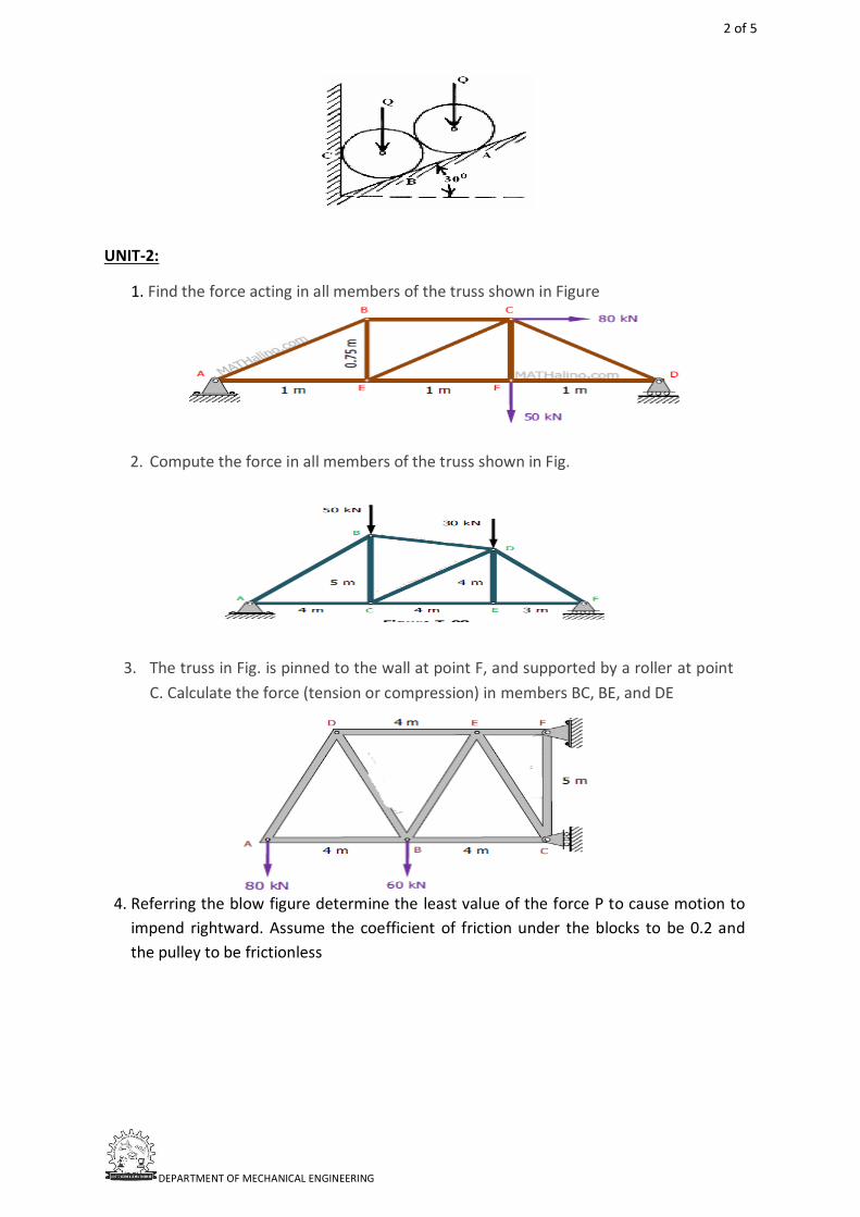
6. Two identical rollers, each of weight 100 N, are supported by an inclined plane and a vertical wall as shown in figure. Assuming smooth surfaces, find the reactions induced at the points of support A, B and C.
MRCET/ ME/ QB/2020-21
December 24, 2020
2 of 5
DEPARTMENT OF MECHANICAL ENGINEERING
UNIT-2:
1. Find the force acting in all members of the truss shown in Figure
2. Compute the force in all members of the truss shown in Fig.
3. The truss in Fig. is pinned to the wall at point F, and supported by a roller at point
C. Calculate the force (tension or compression) in members BC, BE, and DE
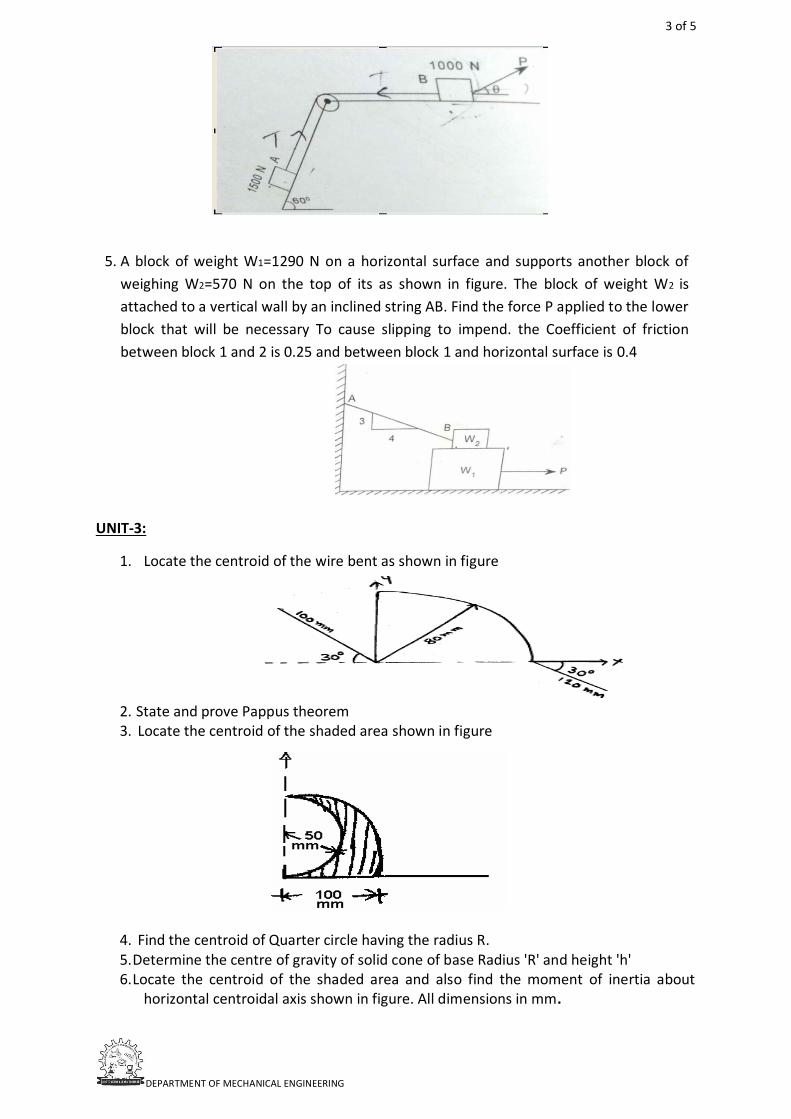
4. Referring the blow figure determine the least value of the force P to cause motion to
impend rightward. Assume the coefficient of friction under the blocks to be 0.2 and
the pulley to be frictionless
3 of 5
DEPARTMENT OF MECHANICAL ENGINEERING
5. A block of weight W1=1290 N on a horizontal surface and supports another block of
weighing W2=570 N on the top of its as shown in figure. The block of weight W2 is
attached to a vertical wall by an inclined string AB. Find the force P applied to the lower
block that will be necessary To cause slipping to impend. the Coefficient of friction
between block 1 and 2 is 0.25 and between block 1 and horizontal surface is 0.4
UNIT-3:
1. Locate the centroid of the wire bent as shown in figure
2. State and prove Pappus theorem 3. Locate the centroid of the shaded area shown in figure
4. Find the centroid of Quarter circle having the radius R. 5. Determine the centre of gravity of solid cone of base Radius 'R' and height 'h' 6. Locate the centroid of the shaded area and also find the moment of inertia about
horizontal centroidal axis shown in figure. All dimensions in mm.
4 of 5
DEPARTMENT OF MECHANICAL ENGINEERING
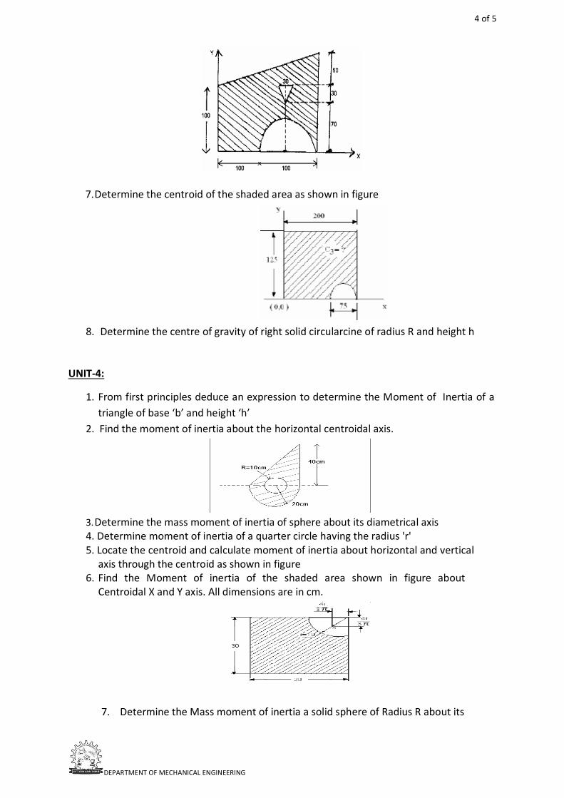
7. Determine the centroid of the shaded area as shown in figure
8. Determine the centre of gravity of right solid circularcine of radius R and height h
UNIT-4:
1. From first principles deduce an expression to determine the Moment of Inertia of a
triangle of base ‘b’ and height ‘h’
2. Find the moment of inertia about the horizontal centroidal axis.
3. Determine the mass moment of inertia of sphere about its diametrical axis
4. Determine moment of inertia of a quarter circle having the radius 'r' 5. Locate the centroid and calculate moment of inertia about horizontal and vertical
axis through the centroid as shown in figure 6. Find the Moment of inertia of the shaded area shown in figure about
Centroidal X and Y axis. All dimensions are in cm.
7. Determine the Mass moment of inertia a solid sphere of Radius R about its
5 of 5
DEPARTMENT OF MECHANICAL ENGINEERING
UNIT-5:
1. Derive the Expression for the Equations of motion of the body when it is accelerated uniformly.
2. State and Explain D’Alemberts principle
3. The motion of a particle in a rectilinear motion is defined by the relation s=2t3-9t2+12t-10 Where s is metres and t in seconds i) Find the acceleration of the particle when velocity is zero ii)the position and total distance travelled when the acceleration is zero
4. A stone is dropped into a well while splash is heard after 4.5 seconds. Another stone is dropped with an initial velocity, v and the splash is heard after 4 seconds. If the velocity of the sound is 336m/s, determine the initial velocity of second stone motorist is travelling at 90 kmph, when he observes a traffic light 250m ahead of him turns red. The traffic light is timed to stay red for 12 sec. If the motorist wishes to pass the light without stopping, just as it turns green. Determine i) The required uniform deceleration of motor and (ii) The speed of the motor as it passes the traffic light
5. Two bodies of weights 40N and 25N are connected to the two ends of a light in extensible spring passing over a smooth pulley. The weight of 40N is placed on a rough horizontal surface while the weight of 25N is hanging free in air. The angle of plane is 150. Determine a) the acceleration of the system b) The tension (µ=0.2) in the string. c) The distance moved by the weight 25N in 3 seconds starting from rest
6. Blocks A and B weighing 500 N and 1500 N respectively are connected by a weightless rope passing over a frictionless pulley as shown in the figure. The coefficient of friction is 0.3 on all contact surfaces. Determine the following using D'Alembert's principle:
i) Tension in the rope. ii) Velocity of the system 5 sec after starting from rest.

THERMODYNAMICS
www.mrcet.ac.in
MALLA REDDY COLLEGE OF ENGINEERING & TECHNOLOGY (Autonomous Institution – UGC, Govt. of India)
DEPARTMENT OF MECHANICAL ENGINEERING
TD QUESTION BANK
UNIT-1:
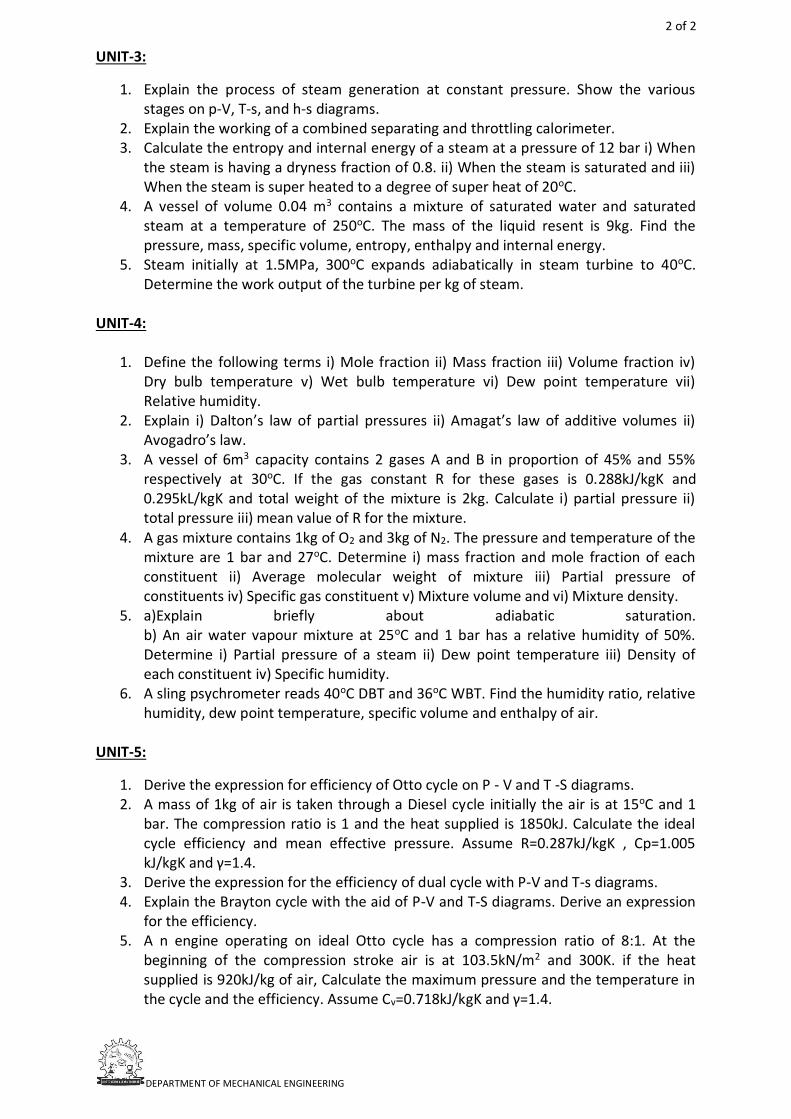
1. Explain first law of thermodynamics with its corollaries. 2. With a neat sketch explain briefly about constant volume gas thermometer. 3. A piston and cylinder machine contains a fluid system which passes through a
complete cycle of four processes. During a cycle, the sum of all heat transfers is -170kJ. The system completes 100 cycles per minute. Complete the following table showing the method for each item and compute the net rate of work output in kW.
Process
Q, kJ/min
w, kJ/min U, kJ/min a-b 0 2170 ----- b-c 21000 0 ------ c-d 2100 ------ -36600 d-a ------ ------ ------
4. A closed system of constant volume experiences a temperature rise of 25°C when a
certain process occurs. The heat transferred in the process is 30 kJ. The specific heat at constant volume for the pure substance comprising the system is 1.2 kJ/kg°C, and the system contains 2.5 kg of this substance. Determine: (i) The change in internal energy ; (ii) The work done.
5. a) Differentiate between Microscopic view and Macroscopic view of study. b) Describe briefly about the quasi-static process.
UNIT-2:
1. State the limitations of second law of thermodynamics. Explain second law of thermodynamics with its corollaries.
2. A heat engine is supplied with 300kJ/s of heat at constant fixed temperature of 3270C with rejection of heat at 70C at the rates of i) 210 ii) 140 and iii) 70kJ/s. Comment on the nature of cycle in each case.
3. Explain the Carnot cycle on p-V and T-s diagrams also derive the expression for the efficiency of Carnot cycle.
4. 2kg of air at a pressure of 7 bar occupies a volume of 0.28m3 This air is then expanded to a volume of 1.4m3. This expansion takes place according to the law pV1.2 = constant. Find work done, change in internal energy, heat absorbed or rejected during the process, change in enthalpy and change in entropy during the process. For air Cp = 1 kJ/kgK and Cv = 0.72 kJ/kg K
5. A Spherical balloon has a diameter of 0.3m and contains a pressure of 147kPa The diameter of the balloon increases to 0.4m due to heating and during this process the pressure proportional to diameter. Calculate the work done during this process.
MRCET/ ME/ QB/2020-21
December 23, 2020
2 of 2
DEPARTMENT OF MECHANICAL ENGINEERING
UNIT-3:
1. Explain the process of steam generation at constant pressure. Show the various stages on p-V, T-s, and h-s diagrams.
2. Explain the working of a combined separating and throttling calorimeter. 3. Calculate the entropy and internal energy of a steam at a pressure of 12 bar i) When
the steam is having a dryness fraction of 0.8. ii) When the steam is saturated and iii) When the steam is super heated to a degree of super heat of 20oC.
4. A vessel of volume 0.04 m3 contains a mixture of saturated water and saturated steam at a temperature of 250oC. The mass of the liquid resent is 9kg. Find the pressure, mass, specific volume, entropy, enthalpy and internal energy.
5. Steam initially at 1.5MPa, 300oC expands adiabatically in steam turbine to 40oC. Determine the work output of the turbine per kg of steam.
UNIT-4:
1. Define the following terms i) Mole fraction ii) Mass fraction iii) Volume fraction iv) Dry bulb temperature v) Wet bulb temperature vi) Dew point temperature vii) Relative humidity.
2. Explain i) Dalton’s law of partial pressures ii) Amagat’s law of additive volumes ii) Avogadro’s law.
3. A vessel of 6m3 capacity contains 2 gases A and B in proportion of 45% and 55% respectively at 30oC. If the gas constant R for these gases is 0.288kJ/kgK and 0.295kL/kgK and total weight of the mixture is 2kg. Calculate i) partial pressure ii) total pressure iii) mean value of R for the mixture.
4. A gas mixture contains 1kg of O2 and 3kg of N2. The pressure and temperature of the mixture are 1 bar and 27oC. Determine i) mass fraction and mole fraction of each constituent ii) Average molecular weight of mixture iii) Partial pressure of constituents iv) Specific gas constituent v) Mixture volume and vi) Mixture density.
5. a)Explain briefly about adiabatic saturation. b) An air water vapour mixture at 25oC and 1 bar has a relative humidity of 50%. Determine i) Partial pressure of a steam ii) Dew point temperature iii) Density of each constituent iv) Specific humidity.
6. A sling psychrometer reads 40oC DBT and 36oC WBT. Find the humidity ratio, relative humidity, dew point temperature, specific volume and enthalpy of air.
UNIT-5:
1. Derive the expression for efficiency of Otto cycle on P - V and T -S diagrams. 2. A mass of 1kg of air is taken through a Diesel cycle initially the air is at 15oC and 1
bar. The compression ratio is 1 and the heat supplied is 1850kJ. Calculate the ideal cycle efficiency and mean effective pressure. Assume R=0.287kJ/kgK , Cp=1.005 kJ/kgK and γ=1.4.
3. Derive the expression for the efficiency of dual cycle with P-V and T-s diagrams. 4. Explain the Brayton cycle with the aid of P-V and T-S diagrams. Derive an expression
for the efficiency. 5. A n engine operating on ideal Otto cycle has a compression ratio of 8:1. At the
beginning of the compression stroke air is at 103.5kN/m2 and 300K. if the heat supplied is 920kJ/kg of air, Calculate the maximum pressure and the temperature in the cycle and the efficiency. Assume Cv=0.718kJ/kgK and γ=1.4.
FLUID MECHANICS & HYDRAULIC MACHINES
www.mrcet.ac.in
MALLA REDDY COLLEGE OF ENGINEERING & TECHNOLOGY (Autonomous Institution – UGC, Govt. of India)
DEPARTMENT OF MECHANICAL ENGINEERING
FMHM QUESTION BANK
UNIT-1:
1. a) Define terms, Weight density, Sp gravity, Viscosity. b) Differentiate between i) Absolute and gauge pressure, ii) simple manometers and differential manometers, and iii) Piezometer and pressure gauge.
2. A U- tube mercury manometer is used to measure the pressure of oil flowing through a pipe whose specific gravity is 0.85. The center of the pipe is 15 cm below the level of mercury. The mercury level difference in the manometer is 25 cm, determine the absolute pressure of the oil flowing through the pipe. Atmospheric pressure is 750 mm of Hg.
3. Find the height through which water rises by capillary action in a glass tube of 2mm diameter, if the surface tension is 0.075N/m. b)A plate 0.05mm distant from a fixed plate moves at 1.2m/s and requires a force of 2.2 N/m to maintain this speed. Find the viscosity of the fluid between the plates.
4. State and Explain Newton’s law of viscosity. Also briefly explain different types of fluids.
5. The space between two parallel square plates each of side 0.8 m is filled with an oil of specific gravity 0.8. If the space between the plates is 12.5mm and the upper plate which moves with velocity of 1.25m/s requires a force of 51.2N. Determine i. Dynamic viscosity of the oil in poise ii. Kinematic viscosity in stokes.
UNIT-2:
1. a) Differentiate the following i. Laminar flow and Turbulent flow. ii. Compressible flow and incompressible flow. b) Derive an equation of continuity of liquid flow. c) Water is flowing through a pipe of 100 mm diameter with an average Velocity of 10 m/s. Determine the rate of discharge of the water in liters/s. Also determine the velocity of water at the other end of the pipe, if the diameter of the pipe is 200 mm.
2. a) State and Prove Bernoulli’s equation from Euler’s equation of motion. Also state its assumptions b) A pipe 300m has a slope of 1 in 100 and tapers from 1m diameter at the higher end to 0.5 m at the lower end. The quantity of water flowing is 900Ltrs/sec. If the pressure at the higher end is 70kPa, find the pressure at lower end.
3. a) What is meant by one-dimensional, two-dimensional and three- dimensional flows? b) Distinguish between: i) Steady flow and un-steady flow ii) Uniform and non-uniform flow iii) Compressible and Incompressible flow iv) Laminar and turbulent flow.
4. A pipe 1 of 450mm in diameter branches into two pipes (2&3) of diameter 300mm and 200mm as shown in fig 2. If average velocity in 450mm diameter pipe is 3m/s.
MRCET/ ME/ QB/2020-21
December 22, 2020
2 of 3
DEPARTMENT OF MECHANICAL ENGINEERING
Find a) Discharge through 450mm diameter pipe. b) Velocity in 200mm diameter pipe if the velocity in 300mm pipe is 2.5m/s.
5. a) How are fluid flows classified? Explain. b) What are the applications of Momentum equation? Explain.
UNIT-3:
1. a) What are the losses in pipes? State and explain Reynold’s experiment. b) Determine the difference in the elevations between the water surfaces in the two tanks which are connected by a horizontal pipe of diameter 400 mm and length 500m. The rate of flow of water through the pipe is 200 litres/s. Consider all the losses and take the value of f=0.009.
2. a) Define and explain the terms: i) Hydraulic gradient line and ii) Total energy line. b) A venturimeter has its axis vertical, the inlet and throat diameters being 150mm and 75mm respectively. The throat is 225mm above inlet and Cd=0.96 and petrol of specific gravity 0.78 flows up through the water meter at a rate of 0.029m3/sec. Find the pressure difference between inlet and throat.
3. A horizontal venturimeter with inlet and throat diameters 30cm and 15cm respectively is used to measure the flow of water. The reading of the differential manometer connected to inlet and throat is 10cm of mercury. Determine the rate of flow. Take Cd= 0.98.
4. a) Derive Darcy Weisbach equation. b) A bend in pipe line conveying water gradually reduces from 0.6 to 0.3mts diameter and deflects through the angle of 600. At the large end the gauge pressure is 171.675KN/m2. Determine the magnitude and direction of force exerted on bend when there is no flow.
5. Two reservoirs are connected by a pipe line consisting of two pipes, one of 15 cm diameter and length 6m and other diameter 22.5cm and 16m length. If the difference of the water levels in the two reservoirs is 6m. Calculate the discharge and draw the energy gradient line. Take f=0.04.
UNIT-4:
1. A Pelton wheel is to be designed for the following specifications. Power= 735.75 kW S.P head= 200m, Speed=800rpm, overall efficiency=0.86 and jet diameter is not to exceed one-tenth the wheel diameter. Determine: (i) Wheel diameter, (ii) the no of jets required and (iii) diameter of the jet. Take Cv=0.98 and speed ratio=0.45
2. A francis turbine with an overall efficiency of 70% is required to produce 147.15 kW. It is working under a head of 8m. The peripheral velocity=0.30√2𝑔ℎ and the radial velocity of flow at inlet is 0.96√2𝑔ℎ. The wheel runs at 200 rpm and the hydraulic losses in the turbine are 20% of the available energy. Assume radial discharge, determine: (i) the guide blade angle, (ii) the wheel vane angle at inlet (iii) the diameter of wheel at inlet and (iv) width of wheel at inlet.
3. One of the Kaplan turbine, installed at Ganguwal power house is rated at 25000 kW when working under 30 m of head at 180 rpm. Find the diameter of the runner, if the overall efficiency of the turbine is 0.91. Assume flow ratio of 0.65 and diameter of runner hub equal to 0.3 times the external diameter of runner. Also find specific speed of the turbine.
3 of 3
DEPARTMENT OF MECHANICAL ENGINEERING
4. a) Derive an equation for force exerted on an unsymmetrical moving curved plate when a jet of water is striking the plate tangentially at one end. b) Define & derive Unit Power, Unit speed, unit discharge.
5. a) Explain performance characteristics curves of turbines? b) Explain with neat sketch parts and working of a Pelton wheel turbine
UNIT-5:
1. a) Define a centrifugal pump. Explain the working of a single stage centrifugal pump with neat sketches. b) Define slip, percentage slip and negative slip of reciprocating pump.
2. A Centrifugal pump delivers water against a net head of 10 m at a design speed of 800 rpm. The vanes are curved backwards and make an angle of 300 with the tangent at the outer periphery. The impeller diameter is 30cm and has a width of 5 cm at the outlet. Determine the discharge of the pump if the manometric efficiency is 85%.
3. a) Define cavitation. What are the effects of cavitation? b) A single acting Reciprocating pump running at 30rpm delivers 0.012 m3 /s of water. The diameter of the piston is 25cm and stroke length is 50 cm. Determine: i) The theoretical discharge of the pump, ii) Co-efficient of discharge, and iii) slip and percentage slip of the pump.
4. A fluid is to be lifted against a head of 120m. The pumps that run at a speed of 1200 rpm with rated capacity of 300litres/sec are available. How many pumps are required to pump the water if specific speed is 70.
5. a) Explain the performance of a centrifugal pump using performance characteristic curves. b) A single acting reciprocating pump having cylinder diameter of 150 mm and stroke 300 mm is used to raise water through a total height of 30m. Find the power required to drive the pump, if the crank rotates at 60 rpm.

MATERIALS ENGINEERING
www.mrcet.ac.in
MALLA REDDY COLLEGE OF ENGINEERING & TECHNOLOGY (Autonomous Institution – UGC, Govt. of India)
DEPARTMENT OF MECHANICAL ENGINEERING
ME QUESTION BANK
UNIT-1:
1. Write in detail about an atom and atomic models? 2. What is a bond and types of bonding's with proper examples? 3. Explain the detail about Ionic and Covalent bonding. Also explain about the strongest
bonding with proper justification. 4. Find the atomic packing factors of BCC, FCC & HCP 5. a) Write short notes on Bravais Lattices.
b) Write in detail about the Pervoskite crystal structure and diamond structure?
UNIT-2:
1. a) What is imperfection in crystal? Explain their effect on properties. b) Explain solidification defects.
2. a) Explain unary and binary equilibrium phase diagram. b) Explain Gibb’s phase rule
3. a) Explain lever rule and different reaction like eutectic, eutectoid & peritectic. b) Explain allotropy of iron.
4. a) Explain iron carbon diagram with critical reactions. b) Explain iron – iron carbon diagram for hypo eutectoid steel and hyper eutectoid steel.
5. a) State Hume-Rothery ’s rules for the formation of substitution solid solution. b) How do you determine the Miller Indices? Explain it with suitable example
UNIT-3:
1. a) Explain about the structure and properties of plain carbon steel. b) Discuss about the structure and properties of Aluminium and its alloys.
2. a) Explain briefly about classification of steels? b) Explain briefly about classification of cast iron?
3. a) Explain super hard materials? b) Explain the ferrous alloys and applications?
4. a) Explain annealing and Normalizing Process? b) Explain difference between annealing and normalizing.
5. a) What is surface hardening process? b) What is Flame hardening & Induction hardening?
MRCET/ ME/ QB/2020-21
December 25, 2020
2 of 2
DEPARTMENT OF MECHANICAL ENGINEERING
UNIT-4:
1. a) Explain briefly types of Ceramic Materials? b) What are the applications and advantages of Ceramic Materials?
2. What is the significance of polymers matrix material in fibre-reinforced composites? Explain briefly.
3. What are carbon composites? Discuss about their micro structure and properties. 4. Define composite material. List the functions of the following: (i) Matrix material. (ii)
Reinforcement materials 5. What are the Classification of composite material (Based on Matrix)?
UNIT-5:
1. Enumerate the characteristics, properties and applications of Polymers. 2. a) Explain the differences between crystallization of polymers and other solids
b) What factors affect the crystallization of polymers? 3. Differentiate between thermoplastic polymers and thermosetting polymers. Give
minimum two examples of each type. 4. What is vulcanization of rubber? Why it is done? 5. a) Explain the differences between crystallization of polymers and other solids
b) What factors affect the crystallization of polymers?

MACHINE DRAWING
www.mrcet.ac.in
MALLA REDDY COLLEGE OF ENGINEERING & TECHNOLOGY (Autonomous Institution – UGC, Govt. of India)
DEPARTMENT OF MECHANICAL ENGINEERING
MD QUESTION BANK
PART-A:
1. Draw the conventional representation all materials?
2. Draw any two views of a hexagonal headed bolt of nominal diameter 25 mm
and length 100mm
3. Sketch the following thread profiles for a nominal diameter of 25 mm and pitch 3
mm and give their applications: (a) BSW thread, (b) Buttress thread (c) Square
thread, (d) ACME thread and (e) Worm thread
4. Draw the three views of a hexagonal headed bolt of nominal diameter 25 mm and
length 100 mm; with a hexagonal nut and washer.
5. Sketch the following types of keys in two views, as fitted in position between a shaft
and the mounting. Choose the shaft diameter as 30 mm and the hub diameter of the
mounting as 60 mm: (a) hollow saddle key, (b) flat saddle key, (c) taper sunk key, (d)
single headed feather key, (e) splines and (f) woodruff key.
6. Draw the sectional view from the front, and view from the side of a cotter joint with
sleeve used to connect two rods of 50 mm diameter each.
7. Draw (a) half sectional view from the front, top half in section and (b) half sectional
view from the side, left half in section, of a split-muff coupling, indicating
proportions to connect two shafts, each of diameter 50 mm.
8. Sketch the sectional view from the front and view from the side of a butt-muff
coupling; indicating proportions for connecting two shafts, each of diameter 30 mm.
9. Sketch the required views of oldham coupling each of diameter 30 mm.
10. Draw (a) sectional view from the front and (b) view from above, of the following
riveted joints, to join plates of thickness 10 mm: (i) single riveted lap joint, (ii) double
riveted chain lap joint, (iii) double riveted zig-zag lap joint, (iv) single riveted, single
strap butt joint, (v) single riveted, double strap butt joint (vi) double riveted, double
strap, chain butt joint and (vii) double riveted, double strap, zig-zag butt joint.
11. Sketch the necessary views of a foot-step bearing, for supporting a shaft of diameter
50mm. Give all important proportionate dimensions.
MRCET/ ME/ QB/2020-21
December 23, 2020
2 of 8
DEPARTMENT OF MECHANICAL ENGINEERING
PART-B:
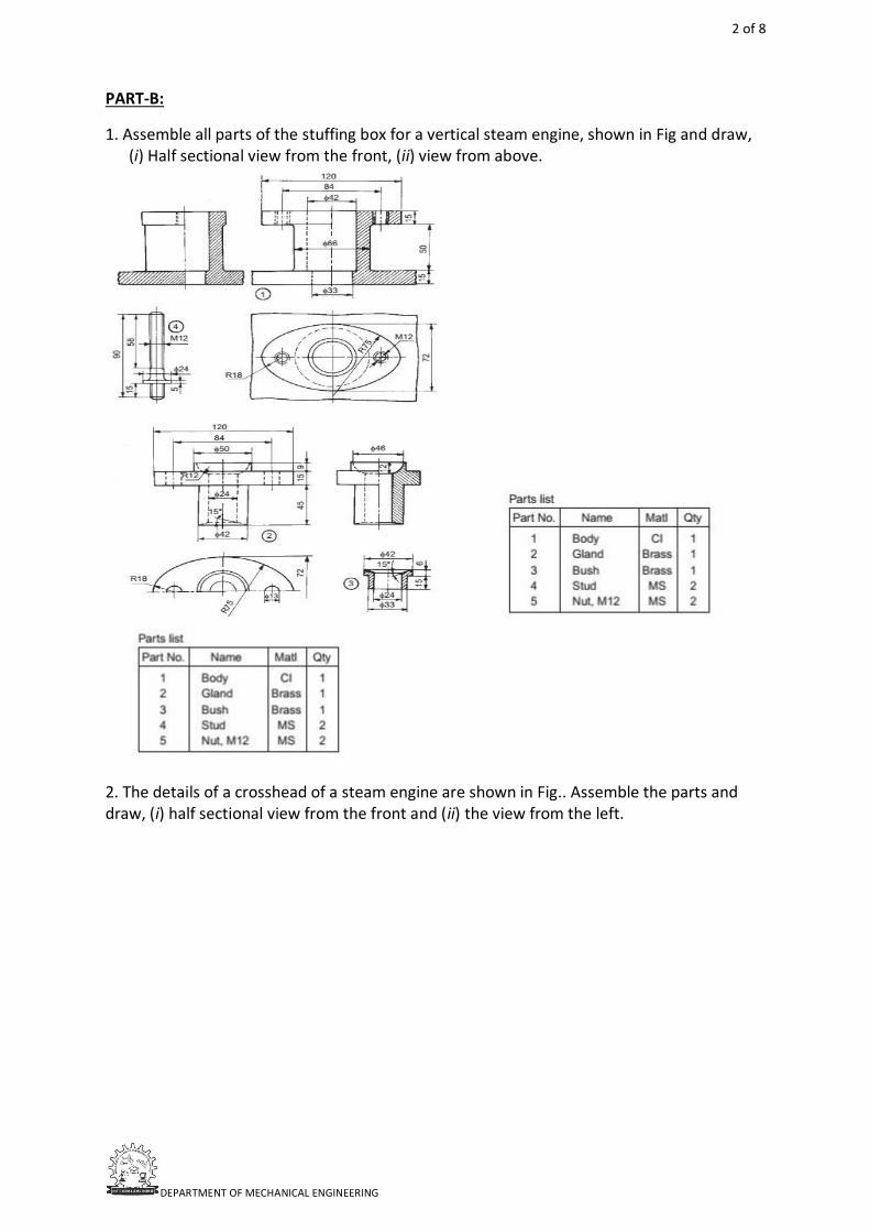
1. Assemble all parts of the stuffing box for a vertical steam engine, shown in Fig and draw, (i) Half sectional view from the front, (ii) view from above.
2. The details of a crosshead of a steam engine are shown in Fig.. Assemble the parts and draw, (i) half sectional view from the front and (ii) the view from the left.
3 of 8
DEPARTMENT OF MECHANICAL ENGINEERING
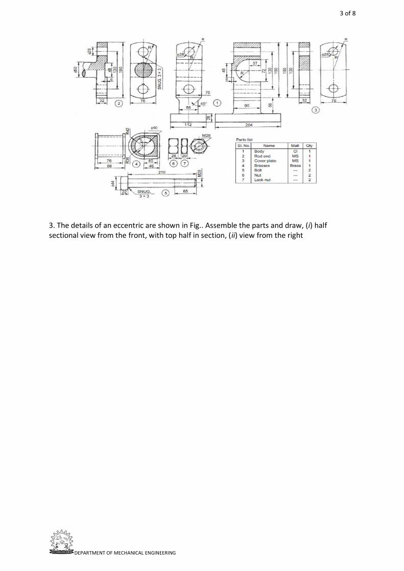
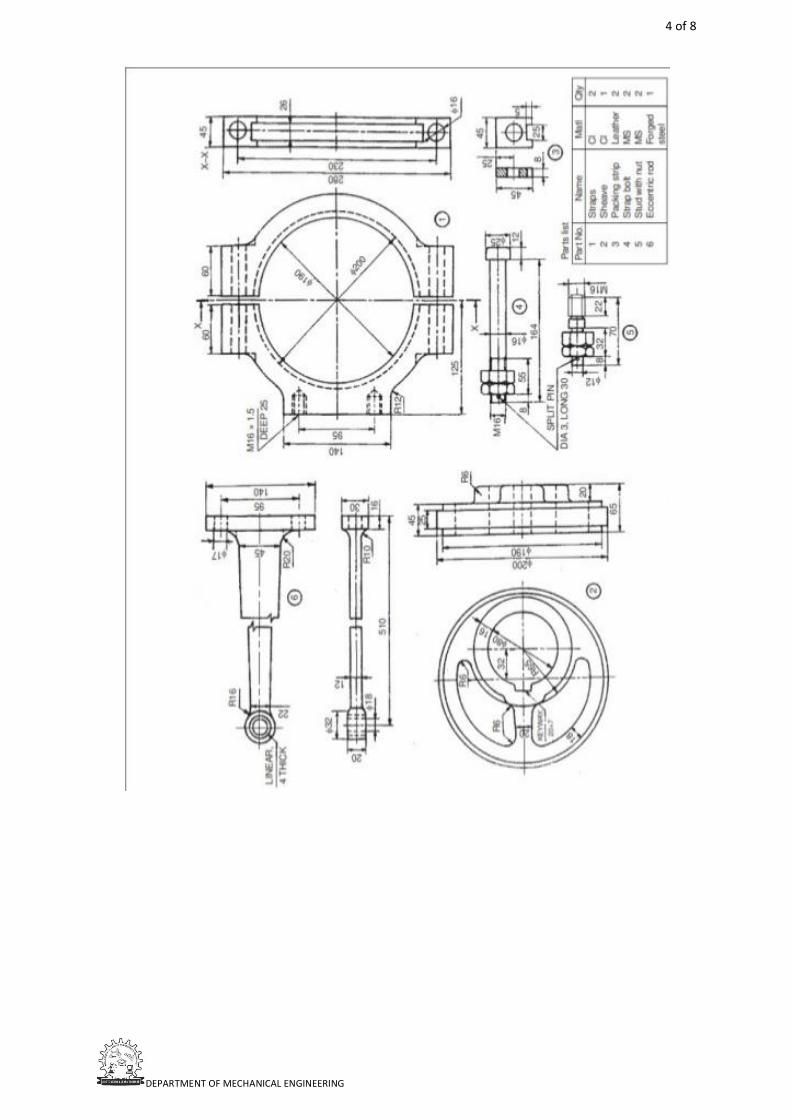
3. The details of an eccentric are shown in Fig.. Assemble the parts and draw, (i) half sectional view from the front, with top half in section, (ii) view from the right
4 of 8
DEPARTMENT OF MECHANICAL ENGINEERING
5 of 8
DEPARTMENT OF MECHANICAL ENGINEERING
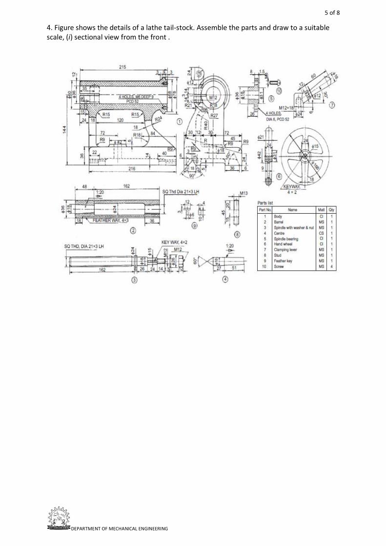
4. Figure shows the details of a lathe tail-stock. Assemble the parts and draw to a suitable scale, (i) sectional view from the front .
6 of 8
DEPARTMENT OF MECHANICAL ENGINEERING
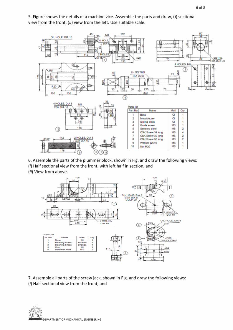
5. Figure shows the details of a machine vice. Assemble the parts and draw, (i) sectional view from the front, (ii) view from the left. Use suitable scale.
6. Assemble the parts of the plummer block, shown in Fig. and draw the following views: (i) Half sectional view from the front, with left half in section, and (ii) View from above.
7. Assemble all parts of the screw jack, shown in Fig. and draw the following views: (i) Half sectional view from the front, and
7 of 8
DEPARTMENT OF MECHANICAL ENGINEERING
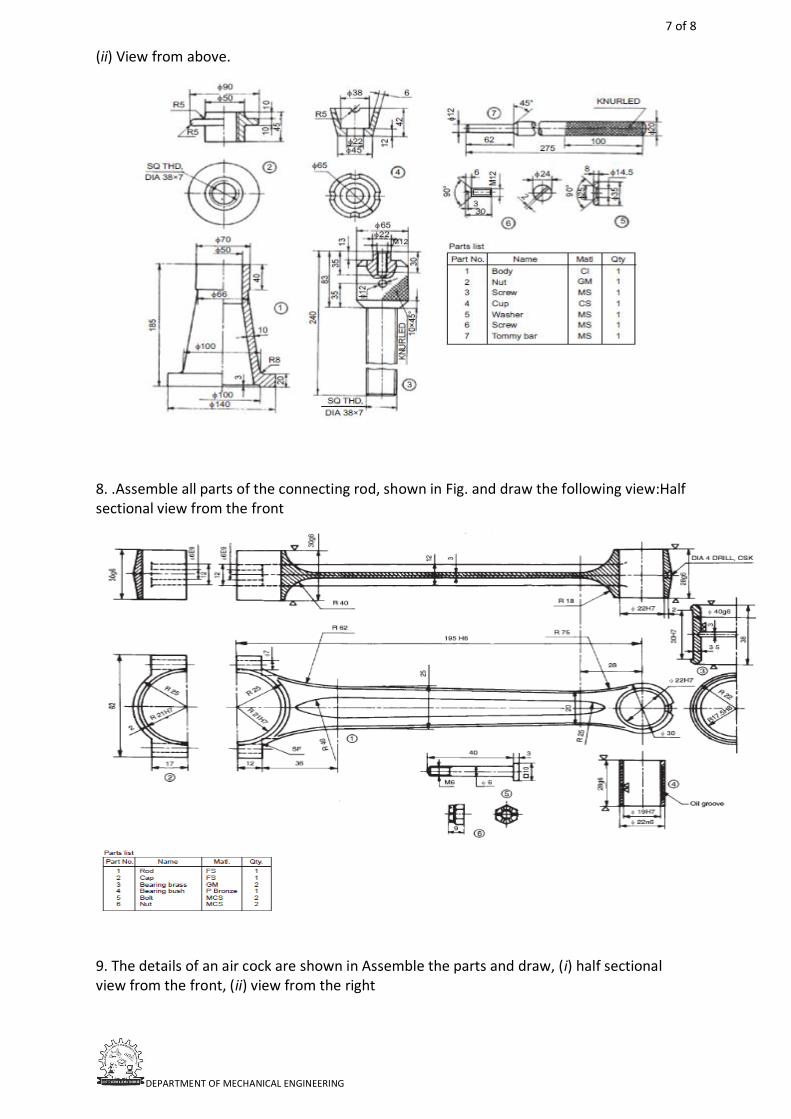
(ii) View from above.
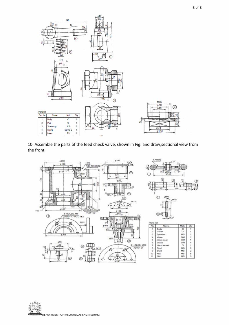
8. .Assemble all parts of the connecting rod, shown in Fig. and draw the following view:Half sectional view from the front
9. The details of an air cock are shown in Assemble the parts and draw, (i) half sectional view from the front, (ii) view from the right
8 of 8
DEPARTMENT OF MECHANICAL ENGINEERING
10. Assemble the parts of the feed check valve, shown in Fig. and draw,sectional view from the front

KINEMATICS OF MACHINERY
www.mrcet.ac.in
MALLA REDDY COLLEGE OF ENGINEERING & TECHNOLOGY (Autonomous Institution – UGC, Govt. of India)
DEPARTMENT OF MECHANICAL ENGINEERING
KOM QUESTION BANK
UNIT-1:
1. Explain different kinds of kinematic pairs giving example for each one of them. 2. Sketch and explain any two inversions of a double slider crank chain. 3. Show that slider crank mechanism is a modification of the basic four bar mechanism. 4. Sketch and describe the four bar chain mechanism. Why it is considered to be the
basic chain? 5. Explain the terms: 1. Lower pair, 2. Higher pair, 3. Kinematic chain, and 4. Inversion.
UNIT-2:
1. What are straight line mechanisms? Describe one type of exact straight line motion mechanism with the help of a sketch.
2. Describe the Watt’s parallel mechanism for straight line motion and derive the condition under which the straight line is traced.
3. Give a neat sketch of the straight line motion ‘Hart mechanism’ Prove that it produces an exact straight line motion.
4. What is the condition for correct steering? Sketch and show the two main types of steering gears and discuss their relative advantages.
5. Explain why two Hooke’s joints are used to transmit motion from the engine to the differential of an automobile.
UNIT-3:
1. In a four bar chain ABCD, AD is fixed and is 150mm long. The crank AB is 40mm long and rotates at 120 rpm clockwise while the link CD=80mm oscillates about D. BC and AD are of equal length. Find the angular velocity and angular acceleration of link CD when angle BAD=600.
2. Locate all the instantaneous centres of the slider crank mechanism. The length of the crank OB and connecting rod AB are 100 mm and 400 mm respectively. If the crank rotates with an angular velocity of 10 rad/s, find: 1) Velocity of the slider A, 2. Angular velocity of the connecting rod AB.
3. In a small steam engine running at 600 rad/min clockwise, length of crank is 80 mm and ratio of connecting rod length to crank radius is 3.For the position when crank makes 450 to horizontal, Determine: A) The velocity and acceleration of pistonB) The angular velocity and angular acceleration of the connecting rod.
4. In a slider crank mechanism, the length of crank OB and connecting rod AB are 125 mm and 500 mm respectively. The centre of gravity G of the connecting rod is 275 mm from the slider A. The crank speed is 600 r.p.m. clockwise. When the crank has turned 45° from the inner dead centre position, determine: 1. velocity of the slider A, 2. velocity of the point G, and 3. angular velocity of the connecting rod AB.
MRCET/ ME/ QB/2020-21
December 24, 2020
2 of 3
DEPARTMENT OF MECHANICAL ENGINEERING
5. In a four bar chain ABCD, link AD is fixed and the crank AB rotates at 10 radians per second clockwise. Lengths of the links are AB= 60 mm; BC= CD= 70 mm; DA= 120 mm. When angle DAB= 60° and both B and C lie on the same side of AD, find 1. angular velocities (magnitude and direction) of BC and CD; and 2. angular acceleration of BC and CD. 4. Describe the Watt’s parallel mechanism for straight line motion and derive the condition under which the straight line is traced.
UNIT-4:
1. A cam is to give the following motion to a knife-edged follower: a) Outstroke during 60° of cam rotation; b) Dwell for the next 30° of cam rotation; c) Return stroke during next 60° of cam rotation, and d) Dwell for the remaining 210° of cam rotation. The stroke of the follower is 40 mm and the minimum radius of the cam is 50 mm. The follower moves with uniform velocity during both the outstroke and return strokes. Draw the profile of the cam when (a) the axis of the follower passes through the axis of the cam shaft, and (b) the axis of the follower is offset by 20 mm from the axis of the cam shaft.
2. A cam is to be designed for a knife edge follower with the following data: 1. Cam lift = 40 mm during 90° of cam rotation with simple harmonic motion. 2. Dwell for the next 30°. 3. During the next 60° of cam rotation, the follower returns to its original position with simple harmonic motion. 4. Dwell during the remaining 180°.Draw the profile of the cam when (a) the line of stroke of the follower passes through the axis of the cam shaft, and (b) the line of stroke is offset 20 mm from the axis of the cam shaft. The radius of the base circle of the cam is 40 mm. Determine the maximum velocity and acceleration of the follower during its ascent and descent, if the cam rotates at 240 r.p.m.
3. Draw the cam profile for the following data: Basic circle radius of cam = 50mm, Lift = 40mm,Angle of ascent with cycloidal = 60°, angle of dwell = 90°, angle of descent with uniform velocity = 90°, speed of cam = 300rpm, Follower offset = 10mm, Type of follower = knife –Edge.
4. Draw the cam profile for the following data: Basic circle radius of cam = 50mm, Lift = 40mm,Angle of ascent with SHM = 90°, Angle of Dwell = 90°, Angle of descent with uniform acceleration and deceleration = 90°, speed of cam = 300 rpm, Type of follower = Roller follower(With roller radius = 10mm).
5. Draw a cam profile which would impart motion to a flat faced follower in the following desired way. The stroke of the follower being 5 cm. (i) The follower to move with uniform acceleration upward for 900 , dwell for next 900, (ii) The follower to return downward with uniform retardation for 1200 and dwell for next 600. The minimum radius of the cam being 3cm.
UNIT-5:
1. Make a comparison of cycloidal and involute tooth forms. b) Two 200 pressure angle involute gears in mesh have a module of 10mm. Addendum is module. Large gear has 50 teeth and the pinion has 13 teeth. Does interference occur? Ifit occurs, to what value should the pressure angle be changed to eliminate interference?
2. Sketch two teeth of a gear and show the following: face, flank, top land, bottomland, addendum, dedendum, tooth thickness, space width, face width and circular pitch. Derive a relation for minimum number of teeth on the gear wheel and the pinion to avoid interference.
3 of 3
DEPARTMENT OF MECHANICAL ENGINEERING
3. Two gears in mesh have a module of 10 mm and a pressure angle of 250. The pinion has 20 teeth and the gear has 52. The addendum on both the gears is equal to one module. Determine (i) The number of pairs of teeth in contact (ii) The angles of action of the pinion and the wheel (iii) The ratio of the sliding velocity to the rolling velocity at the pitch point and at the beginning and end of engagement.
4. What is a worm and worm wheel? Where is it used? Two 200 involute spur gears mesh externally and give a velocity ratio of 3. Module is 3 mm and the addendum is equal to 1.1 module. If the pinion rotates at 120 r.p.m. find: (i) The minimum number of teeth on each wheel to avoid interference. (ii) The number of pairs of teeth in contact.
5. Two involute gears of 20° pressure angle are in mesh. The number of teeth on pinion is 20 and the gear ratio is 2. If the pitch expressed in module is 5 mm, and the pitch line speed is 1.2 m/s, assuming addendum as standard and equal to one module, find (i) the angle turned through by pinion when one pair of teeth is in mesh; and (ii) the maximum velocity of sliding.