levelonedownload.level1.com/level1/manual/gsw-2692(ig).pdf · rfi emission: • limit class a ......
TRANSCRIPT

LevelOne
GSW-2692
24-Port 10/100M + 2G Combo L2 Stackable Switch
Installation Guide
Version 1.0-0608


Compliances and Safety Warnings
FCC - Class AThis equipment generates, uses, and can radiate radio frequency energy and, if not installed and used in accordance with the instruction manual, may cause interference to radio communications. It has been tested and found to comply with the limits for a Class A computing device pursuant to Subpart B of Part 15 of FCC Rules, which are designed to provide reasonable protection against such interference when operated in a commercial environment. Operation of this equipment in a residential area is likely to cause interference, in which case the user, at his own expense, will be required to take whatever measures may be required to correct the interference. You are cautioned that changes or modifications not expressly approved by the party responsible for compliance could void your authority to operate the equipment.
You may use unshielded twisted-pair (UTP) for RJ-45 connections - Category 3 or better for 10 Mbps connections, Category 5 or better for 100 Mbps connections, Category 5, 5e, or 6 for 1000 Mbps connections. For fiber optic connections, you may use 50/125 or 62.5/125 micron multimode fiber or 9/125 micron single-mode fiber.
i

CE Mark Declaration of Conformance for EMI and Safety (EEC)This information technology equipment complies with the requirements of the Council Directive 89/336/EEC on the Approximation of the laws of the Member States relating to Electromagnetic Compatibility and 73/23/EEC for electrical equipment used within certain voltage limits and the Amendment Directive 93/68/EEC. For the evaluation of the compliance with these Directives, the following standards were applied:
Caution: Do not plug a phone jack connector in the RJ-45 port. This may damage this device.
RFI Emission: • Limit class A according to EN 55022:1998
• Limit class A for harmonic current emission according to EN 61000-3-2/1995
• Limitation of voltage fluctuation and flicker in low-voltage supply system according to EN 61000-3-3/1995
Immunity: • Product family standard according to EN 55024:1998
• Electrostatic Discharge according to EN 61000-4-2:1995 (Contact Discharge: ±4 kV, Air Discharge: ±8 kV)
• Radio-frequency electromagnetic field according to EN 61000-4-3:1996 (80 - 1000 MHz with 1 kHz AM 80% Modulation: 3 V/m)
• Electrical fast transient/burst according to EN 61000-4-4:1995 (AC/DC power supply: ±1 kV, Data/Signal lines: ±0.5 kV)
• Surge immunity test according to EN 61000-4-5:1995 (AC/DC Line to Line: ±1 kV, AC/DC Line to Earth: ±2 kV)
• Immunity to conducted disturbances, Induced by radio-frequency fields: EN 61000-4-6:1996 (0.15 - 80 MHz with 1 kHz AM 80% Modulation: 3 V/m)
• Power frequency magnetic field immunity test according to EN 61000-4-8:1993 (1 A/m at frequency 50 Hz)
• Voltage dips, short interruptions and voltage variations immunity test according to EN 61000-4-11:1994 (>95% Reduction @10 ms, 30% Reduction @500 ms, >95% Reduction @5000 ms)
LVD: • EN 60950-1:2001
ii

Safety Compliance
Warning: Fiber Optic Port Safety
Avertissment: Ports pour fibres optiques - sécurité sur le plan optique
Warnhinweis: Faseroptikanschlüsse - Optische Sicherheit
Please read the following safety information carefully before installing the switch:WARNING: Installation and removal of the unit must be carried out by qualified personnel only.
• The unit must be connected to an earthed (grounded) outlet to comply with international safety standards.
• Do not connect the unit to an A.C. outlet (power supply) without an earth (ground) connection.
• The appliance coupler (the connector to the unit and not the wall plug) must have a configuration for mating with an EN 60320/IEC 320 appliance inlet.
• The socket outlet must be near to the unit and easily accessible. You can only remove power from the unit by disconnecting the power cord from the outlet.
• This unit operates under SELV (Safety Extra Low Voltage) conditions according to IEC 60950. The conditions are only maintained if the equipment to which it is connected also operates under SELV conditions.
France and Peru onlyThis unit cannot be powered from IT† supplies. If your supplies are of IT type, this unit must be powered by 230 V (2P+T) via an isolation transformer ratio 1:1, with the secondary connection point labelled Neutral, connected directly to earth (ground).
When using a fiber optic port, never look at the transmit laser while it is powered on. Also, never look directly at the fiber TX port and fiber cable ends when they are powered on.
Ne regardez jamais le laser tant qu'il est sous tension. Ne regardez jamais directement le port TX (Transmission) à fibres optiques et les embouts de câbles à fibres optiques tant qu'ils sont sous tension.
Niemals ein Übertragungslaser betrachten, während dieses eingeschaltet ist. Niemals direkt auf den Faser-TX-Anschluß und auf die Faserkabelenden schauen, während diese eingeschaltet sind.
CLASS I
LASER DEVICE
DISPOSITIF LASER
DE CLASSE I
LASERGER
DER KLASSE I
ÄT
iii

•
Power Cord Set
U.S.A. and Canada The cord set must be UL-approved and CSA certified.
The minimum specifications for the flexible cord are:- No. 18 AWG - not longer than 2 meters, or 16 AWG.- Type SV or SJ- 3-conductor
The cord set must have a rated current capacity of at least 10 A
The attachment plug must be an earth-grounding type with NEMA 5-15P (15 A, 125 V) or NEMA 6-15P (15 A, 250 V) configuration.
Denmark The supply plug must comply with Section 107-2-D1, Standard DK2-1a or DK2-5a.
Switzerland The supply plug must comply with SEV/ASE 1011.
U.K. The supply plug must comply with BS1363 (3-pin 13 A) and be fitted with a 5 A fuse which complies with BS1362.
The mains cord must be <HAR> or <BASEC> marked and be of type HO3VVF3GO.75 (minimum).
Europe The supply plug must comply with CEE7/7 (“SCHUKO”).
The mains cord must be <HAR> or <BASEC> marked and be of type HO3VVF3GO.75 (minimum).
IEC-320 receptacle.
iv

Warnings and Cautionary Messages
Environmental StatementThe manufacturer of this product endeavours to sustain an environmentally-friendly policy throughout the entire production process. This is achieved though the following means:
• Adherence to national legislation and regulations on environmental production standards.
• Conservation of operational resources.• Waste reduction and safe disposal of all harmful un-recyclable by-products. • Recycling of all reusable waste content.• Design of products to maximize recyclables at the end of the product’s life span.• Continual monitoring of safety standards.
End of Product Life SpanThis product is manufactured in such a way as to allow for the recovery and disposal of all included electrical components once the product has reached the end of its life.
Manufacturing MaterialsThere are no hazardous nor ozone-depleting materials in this product.
Warning: This product does not contain any serviceable user parts.Warning: Installation and removal of the unit must be carried out by qualified
personnel only.Warning: When connecting this device to a power outlet, connect the field ground lead
on the tri-pole power plug to a valid earth ground line to prevent electrical hazards.
Warning: This switch uses lasers to transmit signals over fiber optic cable. The lasers are compliant with the requirements of a Class 1 Laser Product and are inherently eye safe in normal operation. However, you should never look directly at a transmit port when it is powered on.
Caution: Wear an anti-static wrist strap or take other suitable measures to prevent electrostatic discharge when handling this equipment.
Caution: Do not plug a phone jack connector in the RJ-45 port. This may damage this device. Les raccordeurs ne sont pas utilisé pour le système téléphonique!
Caution: Use only twisted-pair cables with RJ-45 connectors that conform to FCC standards.
DocumentationAll printed documentation for this product uses biodegradable paper that originates from sustained and managed forests. The inks used in the printing process are non-toxic.
v

PurposeThis guide details the hardware features of the switch, including Its physical and performance-related characteristics, and how to install the switch.
AudienceThis guide is for system administrators with a working knowledge of network management. You should be familiar with switching and networking concepts.
Related PublicationsThe following publication gives specific information on how to operate and use the management functions of the switch:
The Stackable Fast Ethernet Switch Management Guide
Also, as part of the switch’s firmware, there is an online web-based help that describes all management related features.
vi

Contents
Chapter 1: Introduction 1-1Overview 1-1
Switch Architecture 1-2Network Management Options 1-2
Description of Hardware 1-210BASE-T/100BASE-TX Ports 1-21000BASE-T/SFP Ports 1-3Stacking Ports 1-3Port and System Status LEDs 1-4Power Supply Receptacles 1-6
Features and Benefits 1-6Connectivity 1-6Expandability 1-7Performance 1-7Management 1-7
Chapter 2: Network Planning 2-1Introduction to Switching 2-1Application Examples 2-2
Collapsed Backbone 2-2Network Aggregation Plan 2-3Remote Connections with Fiber Cable 2-4Making VLAN Connections 2-5
Application Notes 2-6
Chapter 3: Installing the Switch 3-1Selecting a Site 3-1Ethernet Cabling 3-1Equipment Checklist 3-2
Package Contents 3-2Optional Rack-Mounting Equipment 3-2
Mounting 3-3Rack Mounting 3-3Desktop or Shelf Mounting 3-5
Installing an Optional SFP Transceiver 3-6Connecting Switches in a Stack 3-6Connecting to a Power Source 3-8Connecting to the Console Port 3-8
Wiring Map for Serial Cable 3-9
vii

Contents
Chapter 4: Making Network Connections 4-1Connecting Network Devices 4-1Twisted-Pair Devices 4-1
Cabling Guidelines 4-1Connecting to PCs, Servers, Hubs and Switches 4-2Network Wiring Connections 4-2
Fiber Optic SFP Devices 4-4Connectivity Rules 4-5
1000BASE-T Cable Requirements 4-51000 Mbps Gigabit Ethernet Collision Domain 4-5100 Mbps Fast Ethernet Collision Domain 4-610 Mbps Ethernet Collision Domain 4-6
Cable Labeling and Connection Records 4-6
Appendix A: Troubleshooting A-1Diagnosing Switch Indicators A-1
Diagnosing Power Problems with the LEDs A-1Power and Cooling Problems A-2Installation A-2In-Band Access A-2Stack Troubleshooting A-2
Appendix B: Cables B-1Twisted-Pair Cable and Pin Assignments B-1
10BASE-T/100BASE-TX Pin Assignments B-1Straight-Through Wiring B-2Crossover Wiring B-21000BASE-T Pin Assignments B-3
Fiber Standards B-4
Appendix C: Specifications C-1Switch Features C-2Management Features C-2Standards C-3Compliances C-3
Glossary
Index
viii

ix
Tables
Table 1-1 Port Status LEDs 1-4Table 1-2 System Status LEDs 1-5Table 3-1 Serial Cable Wiring 3-9Table 4-1 Maximum 1000BASE-T Gigabit Ethernet Cable Length 4-5Table 4-2 Maximum 1000BASE-SX Gigabit Ethernet Cable Lengths 4-5Table 4-3 Maximum 1000BASE-LX Gigabit Ethernet Cable Length 4-6Table 4-4 Maximum 1000BASE-ZX Gigabit Ethernet Cable Length 4-6Table 4-5 Maximum Fast Ethernet Cable Length 4-6Table 4-6 Maximum Ethernet Cable Length 4-6Table A-1 Troubleshooting Chart A-1Table A-2 Power/RPU LEDs A-1Table B-1 10/100BASE-TX MDI and MDI-X Port Pinouts B-2Table B-2 1000BASE-T MDI and MDI-X Port Pinouts B-3

x
Figures
Figure 1-1 Front and Rear Panels 1-1Figure 1-2 Stacking Ports 1-3Figure 1-3 Port LEDs 1-4Figure 1-4 System LEDs 1-5Figure 1-5 Power Supply Receptacles 1-6Figure 2-1 Collapsed Backbone 2-2Figure 2-2 Network Aggregation Plan 2-3Figure 2-3 Remote Connections with Fiber Cable 2-4Figure 2-4 Making VLAN Connections 2-5Figure 3-1 RJ-45 Connections 3-2Figure 3-2 Attaching the Brackets 3-3Figure 3-3 Installing the Switch in a Rack 3-4Figure 3-4 Attaching the Adhesive Feet 3-5Figure 3-5 Installing an SFP Transceiver into a slot 3-6Figure 3-6 Connecting Switches in a Ring-topology Stack 3-7Figure 3-7 Power Receptacles 3-8Figure 3-8 Serial Port (DB-9 DTE) Pin-Out 3-8Figure 4-1 Making Twisted-Pair Connections 4-2Figure 4-2 Network Wiring Connections 4-3Figure 4-3 Making Fiber Port Connections 4-4Figure B-1 RJ-45 Connector Pin Numbers B-1Figure B-2 Straight-through Wiring B-2Figure B-3 Crossover Wiring B-3
Chapter 1: Introduction
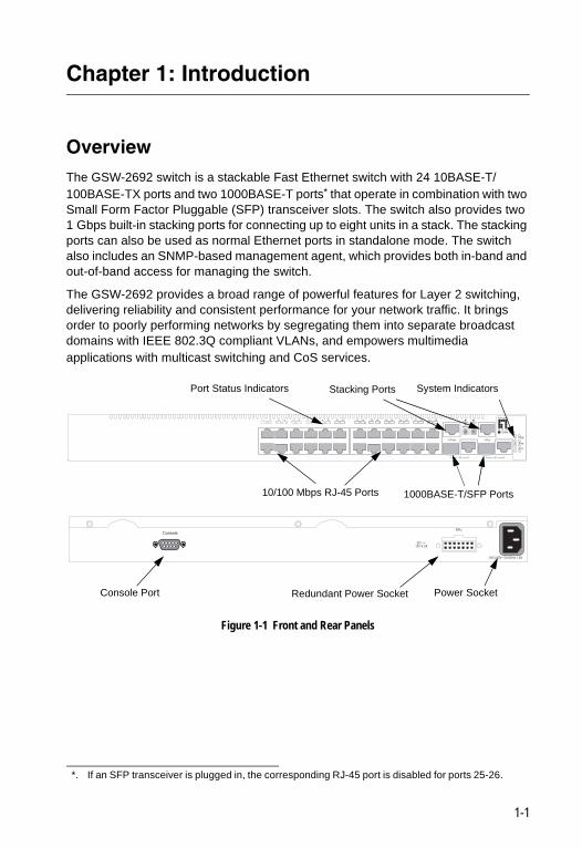
OverviewThe GSW-2692 switch is a stackable Fast Ethernet switch with 24 10BASE-T/100BASE-TX ports and two 1000BASE-T ports* that operate in combination with two Small Form Factor Pluggable (SFP) transceiver slots. The switch also provides two 1 Gbps built-in stacking ports for connecting up to eight units in a stack. The stacking ports can also be used as normal Ethernet ports in standalone mode. The switch also includes an SNMP-based management agent, which provides both in-band and out-of-band access for managing the switch.
The GSW-2692 provides a broad range of powerful features for Layer 2 switching, delivering reliability and consistent performance for your network traffic. It brings order to poorly performing networks by segregating them into separate broadcast domains with IEEE 802.3Q compliant VLANs, and empowers multimedia applications with multicast switching and CoS services.**
Figure 1-1 Front and Rear Panels
*. If an SFP transceiver is plugged in, the corresponding RJ-45 port is disabled for ports 25-26.
Slave Stack
Master UplinkUplink
PWR
Diag
RPU
1 2 3 4 5 6 7 8 9 10 11 12 13 14 15 16 17 18 19 20 21 22 23 24
27/Down 28/Up
25 26
o n e
level®
GSW-2692
100-240V~ 50-60Hz 1.5A
RPU
DC12V 4.5A
Console
10/100 Mbps RJ-45 Ports
Port Status Indicators Stacking Ports
1000BASE-T/SFP Ports
System Indicators
Power SocketRedundant Power SocketConsole Port
1-1

Introduction1
Switch ArchitectureThe GSW-2692 employs a wire-speed, non-blocking switching fabric. This permits simultaneous wire-speed transport of multiple packets at low latency on all ports. The switch also features full-duplex capability on all ports, which effectively doubles the bandwidth of each connection.The switch uses store-and-forward switching to ensure maximum data integrity. With store-and-forward switching, the entire packet must be received into a buffer and checked for validity before being forwarded. This prevents errors from being propagated throughout the network.
The switch includes built-in stacking ports that enable up to eight units to be connected together through a 4 Gbps stack backplane. The switch stack can be managed from a master unit using a single IP address.
Network Management OptionsWith a comprehensive array of LEDs, the GSW-2692 switch provides “at a glance” monitoring of network and port status. The switch can be managed over the network with a web browser or Telnet application, or via a direct connection to the console port. The switch includes a built-in network management agent that allows it to be managed in-band using SNMP or RMON (Groups 1, 2, 3, 9) protocols. It also has an RS-232 serial port (DB-9 connector) on the front panel for out-of-band management. A PC may be connected to this port for configuration and monitoring out-of-band via a null-modem serial cable. (See Appendix B for wiring options.)
For a detailed description of the advanced features, refer to the Management Guide.
Description of Hardware
10BASE-T/100BASE-TX PortsThe GSW-2692 switch base unit contains 24 10BASE-T/100BASE-TX RJ-45 ports. All ports support automatic MDI/MDI-X operation, so you can use straight-through cables for all network connections to PCs or servers, or to other switches or hubs. (See “10BASE-T/100BASE-TX Pin Assignments” on page B-1.)
Each of these ports support auto-negotiation, so the optimum transmission mode (half or full duplex), and data rate (10 or 100 Mbps) can be selected automatically. If a device connected to one of these ports does not support auto-negotiation, the communication mode of that port can be configured manually.
Each port also supports IEEE 802.3x auto-negotiation of flow control, so the switch can automatically prevent port buffers from becoming saturated.
1-2
Description of Hardware 1
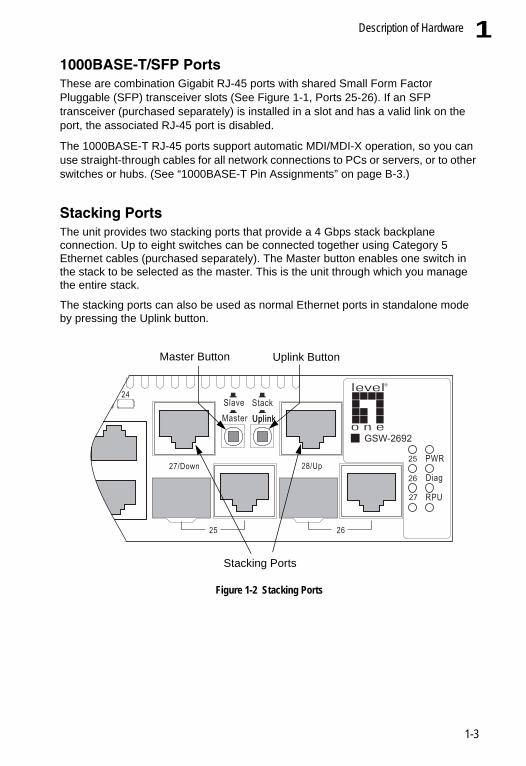
1000BASE-T/SFP PortsThese are combination Gigabit RJ-45 ports with shared Small Form Factor Pluggable (SFP) transceiver slots (See Figure 1-1, Ports 25-26). If an SFP transceiver (purchased separately) is installed in a slot and has a valid link on the port, the associated RJ-45 port is disabled.The 1000BASE-T RJ-45 ports support automatic MDI/MDI-X operation, so you can use straight-through cables for all network connections to PCs or servers, or to other switches or hubs. (See “1000BASE-T Pin Assignments” on page B-3.)
Stacking Ports The unit provides two stacking ports that provide a 4 Gbps stack backplane connection. Up to eight switches can be connected together using Category 5 Ethernet cables (purchased separately). The Master button enables one switch in the stack to be selected as the master. This is the unit through which you manage the entire stack.
The stacking ports can also be used as normal Ethernet ports in standalone mode by pressing the Uplink button.
Figure 1-2 Stacking Ports
Slave Stack
Master UplinkUplink
PWR
Diag
RPU
23 24
27/Down 28/Up
25 26
o n e
level®
GSW-2692
Master Button Uplink Button
Stacking Ports
1-3

Introduction1
Port and System Status LEDs The GSW-2692 includes a display panel for key system and port indications that simplify installation and network troubleshooting. The LEDs, which are located on the front panel for easy viewing, are shown below and described in the following tables.Figure 1-3 Port LEDs
Table 1-1 Port Status LEDsLED Condition StatusFast Ethernet Ports (Ports 1-24)(Link/Activity) On/Flashing
AmberPort has established a valid 10 Mbps network connection. Flashing indicates activity.
On/Flashing Green
Port has established a valid 100 Mbps network connection. Flashing indicates activity.
Off There is no valid link on the port.Gigabit Ethernet Ports (Ports 25-26, and Ports 27-28 when stacking is not implemented)(Link/Activity) On/Flashing
AmberPort has established a valid 10/100 Mbps network connection. Flashing indicates activity.
On/Flashing Green
Port has established a valid 1000 Mbps network connection. Flashing indicates activity.
Off There is no valid link on the port.
1 2 3 4 5 6 7 8 9 10 11 12
Port Status LEDs
1-4
Description of Hardware 1
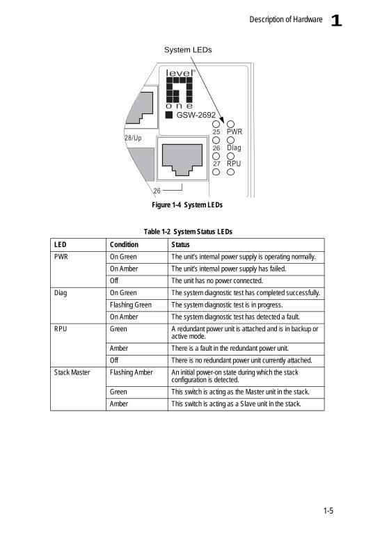
Figure 1-4 System LEDs
Table 1-2 System Status LEDsLED Condition StatusPWR On Green The unit’s internal power supply is operating normally.
On Amber The unit’s internal power supply has failed.Off The unit has no power connected.
Diag On Green The system diagnostic test has completed successfully.Flashing Green The system diagnostic test is in progress.On Amber The system diagnostic test has detected a fault.
RPU Green A redundant power unit is attached and is in backup or active mode.
Amber There is a fault in the redundant power unit.Off There is no redundant power unit currently attached.
Stack Master Flashing Amber An initial power-on state during which the stack configuration is detected.
Green This switch is acting as the Master unit in the stack.Amber This switch is acting as a Slave unit in the stack.
PWR
Diag
RPU
28/Up
26
o n e
level®
GSW-2692
System LEDs
1-5
Introduction1
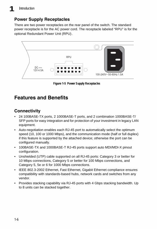
Power Supply ReceptaclesThere are two power receptacles on the rear panel of the switch. The standard power receptacle is for the AC power cord. The receptacle labeled “RPU” is for the optional Redundant Power Unit (RPU).Figure 1-5 Power Supply Receptacles
Features and Benefits
Connectivity• 24 100BASE-TX ports, 2 1000BASE-T ports, and 2 combination 1000BASE-T/
SFP ports for easy integration and for protection of your investment in legacy LAN equipment.
• Auto-negotiation enables each RJ-45 port to automatically select the optimum speed (10, 100 or 1000 Mbps), and the communication mode (half or full duplex) if this feature is supported by the attached device; otherwise the port can be configured manually.
• 100BASE-TX and 1000BASE-T RJ-45 ports support auto MDI/MDI-X pinout configuration.
• Unshielded (UTP) cable supported on all RJ-45 ports: Category 3 or better for 10 Mbps connections, Category 5 or better for 100 Mbps connections, and Category 5, 5e or 6 for 1000 Mbps connections.
• IEEE 802.3-2002 Ethernet, Fast Ethernet, Gigabit Ethernet compliance ensures compatibility with standards-based hubs, network cards and switches from any vendor.
• Provides stacking capability via RJ-45 ports with 4 Gbps stacking bandwidth. Up to 8 units can be stacked together.
100-240V~ 50-60Hz 1.5A
RPU
DC12V 4.5A
1-6

Features and Benefits 1
Expandability• 2 Small Form Factor Pluggable (SFP) transceiver slots (shared with 1000BASE-Tports)• Supports 1000BASE-SX, 1000BASE-LX and 1000BASE-ZX SFP transceivers.
Performance• Transparent bridging• Aggregate duplex bandwidth of up to 12.8 Gbps• Switching table with a total of 8K MAC address entries• Provides store-and-forward switching• Wire-speed filtering and forwarding• Supports flow control, using back pressure for half duplex and IEEE 802.3x for full
duplex• Broadcast storm control
Management• “At-a-glance” LEDs for easy troubleshooting• Network management agent:
- Manages switch in-band or out-of-band- Supports SSH, Telnet, SNMP (v1/v2), RMON (4 groups) and web-based
interface
1-7

Introduction1
1-8

Chapter 2: Network Planning
Introduction to SwitchingA network switch allows simultaneous transmission of multiple packets via non-crossbar switching. This means that it can partition a network more efficiently than bridges or routers. The switch has, therefore, been recognized as one of the most important building blocks for today’s networking technology.
When performance bottlenecks are caused by congestion at the network access point (such as the network card for a high-volume file server), the device experiencing congestion (server, power user, or hub) can be attached directly to a switched port. And, by using full-duplex mode, the bandwidth of the dedicated segment can be doubled to maximize throughput.
When networks are based on repeater (hub) technology, the distance between end stations is limited by a maximum hop count. However, a switch turns the hop count back to zero. So subdividing the network into smaller and more manageable segments, and linking them to the larger network by means of a switch, removes this limitation.
A switch can be easily configured in any Ethernet, Fast Ethernet, or Gigabit Ethernet network to significantly boost bandwidth while using conventional cabling and network cards.
2-1

Network Planning2
Application ExamplesThe GSW-2692 is not only designed to segment your network, but also to provide a wide range of options in setting up network connections. Some typical applications are described below.Collapsed BackboneThe GSW-2692 is an excellent choice for mixed Ethernet, Fast Ethernet, and Gigabit Ethernet installations where significant growth is expected in the near future. You can easily build on this basic configuration, adding direct full-duplex connections to workstations or servers. When the time comes for further expansion, just connect to another hub or switch using one of the Fast Ethernet or Gigabit Ethernet ports.
In the figure below, the switch is operating as a collapsed backbone for a small LAN. It is providing dedicated 10 Mbps full-duplex connections to workstations, 100 Mbps full-duplex connections to power users, and 1 Gbps full-duplex connections to servers.
Figure 2-1 Collapsed Backbone
Servers1 GbpsFull Duplex
Workstations100 MbpsFull Duplex
Workstations10 MbpsFull Duplex
... ... ...
Slave Stack
Master UplinkUplink
PWR
Diag
RPU
1 2 3 4 5 6 7 8 9 10 11 12 13 14 15 16 17 18 19 20 21 22 23 24
27/Down 28/Up
25 26
o n e
level®
GSW-2692
2-2
Application Examples 2
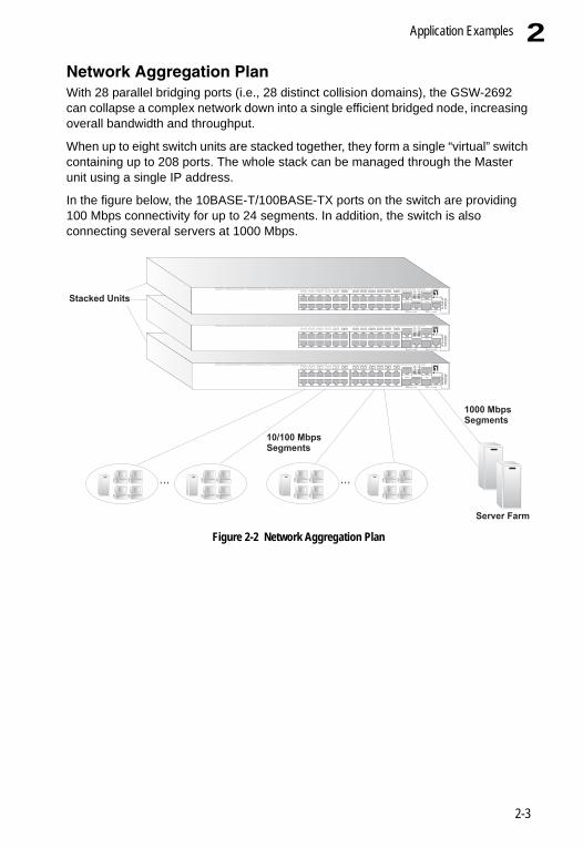
Network Aggregation PlanWith 28 parallel bridging ports (i.e., 28 distinct collision domains), the GSW-2692 can collapse a complex network down into a single efficient bridged node, increasing overall bandwidth and throughput.When up to eight switch units are stacked together, they form a single “virtual” switch containing up to 208 ports. The whole stack can be managed through the Master unit using a single IP address.
In the figure below, the 10BASE-T/100BASE-TX ports on the switch are providing 100 Mbps connectivity for up to 24 segments. In addition, the switch is also connecting several servers at 1000 Mbps.
Figure 2-2 Network Aggregation Plan
Server Farm
10/100 MbpsSegments
... ...
Stacked Units
1000 MbpsSegments
Slave Stack
Master UplinkUplink
PWR
Diag
RPU
1 2 3 4 5 6 7 8 9 10 11 12 13 14 15 16 17 18 19 20 21 22 23 24
27/Down 28/Up
25 26
o n e
level®
GSW-2692
Slave Stack
Master UplinkUplink
PWR
Diag
RPU
1 2 3 4 5 6 7 8 9 10 11 12 13 14 15 16 17 18 19 20 21 22 23 24
27/Down 28/Up
25 26
o n e
level®
GSW-2692
Slave Stack
Master UplinkUplink
PWR
Diag
RPU
1 2 3 4 5 6 7 8 9 10 11 12 13 14 15 16 17 18 19 20 21 22 23 24
27/Down 28/Up
25 26
o n e
level®
GSW-2692
2-3

Network Planning2
Remote Connections with Fiber CableFiber optic technology allows for longer cabling than any other media type. A 1000BASE-SX (MMF) link can connect to a site up to 550 meters away, a 1000BASE-LX (SMF) link up to 10 km, and a 1000BASE-ZX link up to 70 km. This allows a Gigabit Ethernet Switch to serve as a collapsed backbone, providing direct connectivity for a widespread LAN.The figure below illustrates this switch connecting multiple segments with fiber cable.
Figure 2-3 Remote Connections with Fiber Cable
... ...
Headquarters
1000BASE-LX SMF(10 kilometers)
Remote Switch
10/100 Mbps Segments
(70 kilometers)
Remote SwitchC
Server Farm
Slave Stack
Master UplinkUplink
PWR
Diag
RPU
1 2 3 4 5 6 7 8 9 10 11 12 13 14 15 16 17 18 19 20 21 22 23 24
27/Down 28/Up
25 26
o n e
level®
GSW-2692
Slave Stack
Master UplinkUplink
PWR
Diag
RPU
1 2 3 4 5 6 7 8 9 10 11 12 13 14 15 16 17 18 19 20 21 22 23 24
27/Down 28/Up
25 26
o n e
level®
GSW-2692
Slave Stack
Master UplinkUplink
PWR
Diag
RPU
1 2 3 4 5 6 7 8 9 10 11 12 13 14 15 16 17 18 19 20 21 22 23 24
27/Down 28/Up
25 26
o n e
level®
GSW-2692
1000BASE-ZX SMF
2-4

Application Examples 2
Making VLAN ConnectionsThis switch supports VLANs which can be used to organize any group of network nodes into separate broadcast domains. VLANs confine broadcast traffic to the originating group, and can eliminate broadcast storms in large networks. This provides a more secure and cleaner network environment.VLANs can be based on untagged port groups, or traffic can be explicitly tagged to identify the VLAN group to which it belongs. Untagged VLANs can be used for small networks attached to a single switch. However, tagged VLANs should be used for larger networks, and all the VLANs assigned to the inter-switch links.
Figure 2-4 Making VLAN Connections
Note: When connecting to a switch that does not support IEEE 802.1Q VLAN tags, use untagged ports.
Finance
Untagged Ports
VLANunawareswitch
Tagged Port
R&D
Testing
VLAN 1
VLAN 2
Marketing
VLAN 3
Finance
VLAN 3
VLAN 4
VLANawareswitch
R&D
VLAN 2Testing
VLAN 1
TaggedPorts
Slave Stack
Master UplinkUplink
PWR
Diag
RPU
StackMaster
1 2 3 4 5 6 7 8 9 10 11 12 13 14 15 16 17 18 19 20 21 22 23 24
27/Down 28/Up
25 26
o n e
level®
GSW-2692
2-5

Network Planning2
Application Notes1. Full-duplex operation only applies to point-to-point access (such as when aswitch is attached to a workstation, server or another switch). When the switch is connected to a hub, both devices must operate in half-duplex mode.
2. Avoid using flow control on a port connected to a hub unless it is actually required to solve a problem. Otherwise back pressure jamming signals may degrade overall performance for the segment attached to the hub.
3. As a general rule the length of fiber optic cable for a single switched link should not exceed:
• 1000BASE-SX: 550 m (1805 ft) for multimode fiber.• 1000BASE-LX: 10 km (6.2 miles) for singlemode fiber.• 1000BASE-ZX: 70 km (43.5 miles) for singlemode fiber.However, power budget constraints must also be considered when calculating the maximum cable length for your specific environment.
2-6
Chapter 3: Installing the Switch
Selecting a SiteSwitch units can be mounted in a standard 19-inch equipment rack or on a flat surface. Be sure to follow the guidelines below when choosing a location.
• The site should:- be at the center of all the devices you want to link and near a power outlet.
- be able to maintain its temperature within 0 to 40 °C (32 to 104 °F) and its humidity within 5% to 95%, non-condensing
- provide adequate space (approximately two inches) on all sides for proper air flow
- be accessible for installing, cabling and maintaining the devices
- allow the status LEDs to be clearly visible
• Make sure twisted-pair cable is always routed away from power lines, fluorescent lighting fixtures and other sources of electrical interference, such as radios and transmitters.
• Make sure that the unit is connected to a separate grounded power outlet that provides 100 to 240 VAC, 50 to 60 Hz, is within 2 m (6.6 feet) of each device and is powered from an independent circuit breaker. As with any equipment, using a filter or surge suppressor is recommended.
Ethernet CablingTo ensure proper operation when installing the switch into a network, make sure that the current cables are suitable for 10BASE-T, 100BASE-TX or 1000BASE-T operation. Check the following criteria against the current installation of your network:
• Cable type: Unshielded twisted pair (UTP) or shielded twisted pair (STP) cables with RJ-45 connectors; Category 3 or better for 10BASE-T, Category 5 or better for 100BASE-TX, and Category 5, 5e or 6 for 1000BASE-T.
• Protection from radio frequency interference emissions• Electrical surge suppression• Separation of electrical wires (switch related or other) and electromagnetic fields
from data based network wiring• Safe connections with no damaged cables, connectors or shields
3-1

Installing the Switch3
Figure 3-1 RJ-45 Connections
Equipment ChecklistAfter unpacking this switch, check the contents to be sure you have received all the components. Then, before beginning the installation, be sure you have all other necessary installation equipment.
Package Contents• GSW-2692• Four adhesive foot pads• Bracket Mounting Kit containing two brackets and eight screws for attaching the
brackets to the switch• Power Cord• RS-232 console cable• CD Manual/Management Guide
Optional Rack-Mounting EquipmentIf you plan to rack-mount the switch, be sure to have the following equipment available:
• Four mounting screws for each device you plan to install in a rack—these are not included
• A screwdriver
RJ-45 Connector
3-2
Mounting 3
MountingThis switch can be mounted in a standard 19-inch equipment rack or on a desktop or shelf. Mounting instructions for each type of site follow.Rack MountingBefore rack mounting the switch, pay particular attention to the following factors:
• Temperature: Since the temperature within a rack assembly may be higher than the ambient room temperature, check that the rack-environment temperature is within the specified operating temperature range. (See page C-1.)
• Mechanical Loading: Do not place any equipment on top of a rack-mounted unit.• Circuit Overloading: Be sure that the supply circuit to the rack assembly is not
overloaded.• Grounding: Rack-mounted equipment should be properly grounded. Particular
attention should be given to supply connections other than direct connections to the mains.
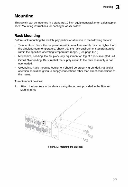
To rack-mount devices:
1. Attach the brackets to the device using the screws provided in the Bracket Mounting Kit.
Figure 3-2 Attaching the Brackets
Slave StackMaster UplinkUplink
PWR
Diag
RPU
27/Down
28/Up
25
26
o n e
level®
GSW-2692
3-3

Installing the Switch3
2. Mount the device in the rack, using four rack-mounting screws (not provided).Figure 3-3 Installing the Switch in a Rack
3. If installing a single switch only, turn to “Connecting to a Power Source” at the end of this chapter.
4. If installing multiple switches, mount them in the rack, one below the other, in any order.
5. If also installing RPUs, mount them in the rack below the other devices.
Slave StackMaster UplinkUplink
PWR
Diag
RPU
1920
2122
2324
27/Down
28/Up
25
26
o n e
level®
GSW-2692
3-4

Mounting 3
Desktop or Shelf Mounting1. Attach the four adhesive feet to the bottom of the first switch.Figure 3-4 Attaching the Adhesive Feet
2. Set the device on a flat surface near an AC power source, making sure there are at least two inches of space on all sides for proper air flow.
3. If installing a single switch only, go to “Connecting to a Power Source” at the end of this chapter.
4. If installing multiple switches, attach four adhesive feet to each one. Place each device squarely on top of the one below, in any order.
5. If also installing RPUs, place them close to the stack.
SlaveStack MasterUplinkUplink
PWR
Diag
RPU
12
34
56
78
910
1112
1314
1516
1718
1920
2122
2324
27/Down
28/Up
25
26
o n e
level®
GSW-2692
3-5

Installing the Switch3
Installing an Optional SFP TransceiverFigure 3-5 Installing an SFP Transceiver into a slot
This switch supports 1000BASE-SX, 1000BASE-LX, and 1000BASE-ZX SFP transceivers. To install an SFP transceiver, do the following:
1. Consider network and cabling requirements to select an appropriate SFP transceiver type.
2. Insert the transceiver with the optical connector facing outward and the slot connector facing down. Note that SFP transceivers are keyed so they can only be installed in one orientation.
3. Slide the SFP transceiver into the slot until it clicks into place.
Note: SFP transceivers are hot-swappable. The switch does not need to be powered off before installing or removing a transceiver. However, always first disconnect the network cable before removing a transceiver.
Note: SFP transceivers are not provided in the switch package.
Connecting Switches in a StackFigure 3-6 shows how the stack cables are connected between switches in a stack. The connection is based on Gigabit Ethernet, using Category 5 or better cables. The switch supports a line- and ring-topology stacking configuration, or can be used stand alone.
In line-topology stacking there is a single stack cable connection between each switch that carries two-way communications across the stack. In ring-topology stacking, an extra cable is connected between the top and bottom switches forming a “ring” or “closed-loop.” The closed-loop cable provides a redundant path for the stack link, so if one link fails, stack communications can be maintained. Figure 3-6 illustrates a ring-topology stacking configuration.
Slave StackMaster UplinkUplink
PWR
Diag
RPU
1314
1516
1718
1920
2122
2324
27/Down
28/Up
25
26
o n e
level®
GSW-2692
3-6

Connecting Switches in a Stack 3
To connect up to eight switches in a stack, perform the following steps:1. Enable the stacking ports on each unit (i.e., the Stack button pushed out)
Note: Pressing the Stack button during normal operation will cause the system to reboot.
2. Plug one end of a stack cable (ordered separately) into the Down (left) port of the top unit.
3. Plug the other end of the stack cable into the Up (right) port of the next unit.
4. Repeat steps 1 and 2 for each unit in the stack. Form a simple chain starting at the Down port on the top unit and ending at the Up port on the bottom unit (stacking up to 8 units).
5. (Optional) To form a wrap-around topology, plug one end of a stack cable into the Down port on the bottom unit and the other end into the Up port on the top unit.
Figure 3-6 Connecting Switches in a Ring-topology Stack
6. Select the Master unit in the stack by pressing in the Master button on only one of the switches. Only one switch in the stack can operate as the Master, all other units operate in slave mode. If more than one switch in the stack is selected as Master, or if no switches are selected, the stack will not function.
19/20 21/22 23/24
19 20 21 22 23 24 27 28
25 26
19/20 21/22 23/24
19 20 21 22 23 24 27 28
25 26
19/20 21/22 23/24
19 20 21 22 23 24 27 28
25 26
PWR
Diag
RPU
StackMaster
PWR
Diag
RPU
StackMaster
PWR
Diag
RPU
StackMaster
o n e
level®
GSW-2692
o n e
level®
GSW-2692
o n e
level®
GSW-2692
3-7

Installing the Switch3
Connecting to a Power SourceTo connect a switch to a power source:1. Insert the power cable plug directly into the AC receptacle located at the back of the switch.
Figure 3-7 Power Receptacles
2. Plug the other end of the cable into a grounded, 3-pin, AC power source.
Note: For International use, you may need to change the AC line cord. You must use a line cord set that has been approved for the receptacle type in your country.
3. Check the front-panel LEDs as the device is powered on to be sure the PWR LED is lit. If not, check that the power cable is correctly plugged in.
4. If you have purchased a Redundant Power Unit, connect it to the switch and to an AC power source now, following the instructions included with the package.
Connecting to the Console Port The DB-9 serial port on the switch’s back panel is used to connect to the switch for out-of-band console configuration. The command-line-driven configuration program can be accessed from a terminal or a PC running a terminal emulation program. The pin assignments used to connect to the serial port are provided in the following table.
Figure 3-8 Serial Port (DB-9 DTE) Pin-Out
100-240V~ 50-60Hz 1.5A
RPU
DC12V 4.5A
1 5
6 9
3-8

Connecting to the Console Port 3
Wiring Map for Serial CableThe serial port’s configuration requirements are as follows:• Default Baud rate—9,600 bps• Character Size—8 Characters• Parity—None• Stop bit—One• Data bits—8
Table 3-1 Serial Cable Wiring
Switch’s 9-Pin Serial Port
Null Modem PC’s 9-Pin DTE Port
2 RXD (receive data) <---------------------------- 3 TXD (transmit data)3 TXD (transmit data) -----------------------------> 2 RXD (receive data)5 SGND (signal ground) ------------------------------ 5 SGND (signal ground)No other pins are used.
3-9

Installing the Switch3
3-10

Chapter 4: Making Network Connections
Connecting Network DevicesThe GSW-2692 is designed to be connected to 10, 100 or 1000 Mbps network cards in PCs and servers, as well as to other switches and hubs. It may also be connected to remote devices using optional 1000BASE-SX, 1000BASE-LX, or 1000BASE-ZX SFP transceivers.
Twisted-Pair DevicesEach device requires an unshielded twisted-pair (UTP) cable with RJ-45 connectors at both ends. Use Category 5, 5e or 6 cable for 1000BASE-T connections, Category 5 or better for 100BASE-TX connections, and Category 3 or better for 10BASE-T connections.
Cabling GuidelinesThe RJ-45 ports on the switch support automatic MDI/MDI-X pinout configuration, so you can use standard straight-through twisted-pair cables to connect to any other network device (PCs, servers, switches, routers, or hubs).
See Appendix B for further information on cabling.
Caution: Do not plug a phone jack connector into an RJ-45 port. This will damage the switch. Use only twisted-pair cables with RJ-45 connectors that conform to FCC standards.
4-1

Making Network Connections4
Connecting to PCs, Servers, Hubs and Switches1. Attach one end of a twisted-pair cable segment to the device’s RJ-45connector.
Figure 4-1 Making Twisted-Pair Connections
2. If the device is a network card and the switch is in the wiring closet, attach the other end of the cable segment to a modular wall outlet that is connected to the wiring closet. (See the section “Network Wiring Connections.”) Otherwise, attach the other end to an available port on the switch.
Make sure each twisted pair cable does not exceed 100 meters (328 ft) in length.
Note: Avoid using flow control on a port connected to a hub unless it is actually required to solve a problem. Otherwise back pressure jamming signals may degrade overall performance for the segment attached to the hub.
3. As each connection is made, the Link LED (on the switch) corresponding to each port will light to indicate that the connection is valid.
Network Wiring ConnectionsToday, the punch-down block is an integral part of many of the newer equipment racks. It is actually part of the patch panel. Instructions for making connections in the wiring closet with this type of equipment follows.
1. Attach one end of a patch cable to an available port on the switch, and the other end to the patch panel.
2. If not already in place, attach one end of a cable segment to the back of the patch panel where the punch-down block is located, and the other end to a modular wall outlet.
4-2
Twisted-Pair Devices 4
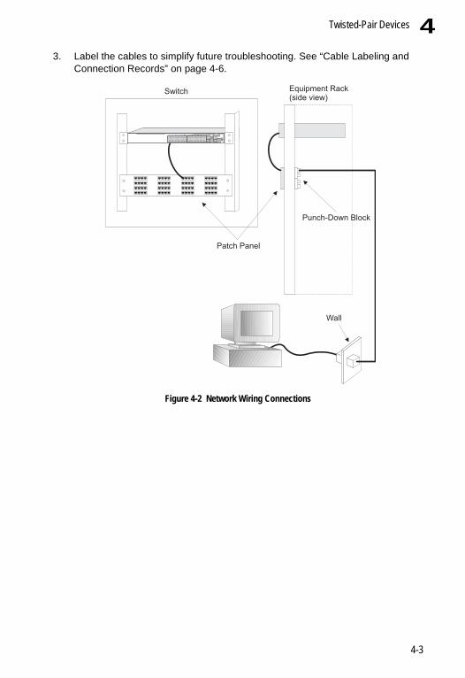
3. Label the cables to simplify future troubleshooting. See “Cable Labeling andConnection Records” on page 4-6.
Figure 4-2 Network Wiring Connections
Equipment Rack(side view)
Switch
Patch Panel
Punch-Down Block
Wall
Slave Stack
Master UplinkUplink
PWR
Diag
RPU
1 2 3 4 5 6 7 8 9 10 11 12 13 14 15 16 17 18 19 20 21 22 23 24
27/Down 28/Up
25 26
o n e
level®
GSW-2692
4-3

Making Network Connections4
Fiber Optic SFP DevicesAn optional Gigabit SFP transceiver (1000BASE-SX, 1000BASE-LX, or 1000BASE-ZX) can be used for a backbone connection between switches, or for connecting to a high-speed server.Each single-mode fiber port requires 9/125 micron single-mode fiber optic cable with an LC connector at both ends. Each multimode fiber optic port requires 50/125 or 62.5/125 micron multimode fiber optic cabling with an LC connector at both ends.
Warning: This switch uses lasers to transmit signals over fiber optic cable. The lasers are compliant with the requirements of a Class 1 Laser Product and are inherently eye safe in normal operation. However, you should never look directly at a transmit port when it is powered on.
Note: When selecting a fiber SFP device, considering safety, please make sure that it can function at a temperature that is not less than the recommended maximum operational temperature of the product. You must also use an approved Laser Class 1 SFP transceiver.
1. Remove and keep the LC port’s rubber plug. When not connected to a fiber cable, the rubber plug should be replaced to protect the optics.
2. Check that the fiber terminators are clean. You can clean the cable plugs by wiping them gently with a clean tissue or cotton ball moistened with a little ethanol. Dirty fiber terminators on fiber optic cables will impair the quality of the light transmitted through the cable and lead to degraded performance on the port.
3. Connect one end of the cable to the LC port on the switch and the other end to the LC port on the other device. Since LC connectors are keyed, the cable can be attached in only one orientation.
Figure 4-3 Making Fiber Port Connections
Slave StackMaster UplinkUplink
PWR
Diag
RPU
1516
1718
1920
2122
2324
27/Down
28/Up
25
26
o n e
level®
GSW-2692
46
4-4
Connectivity Rules 4
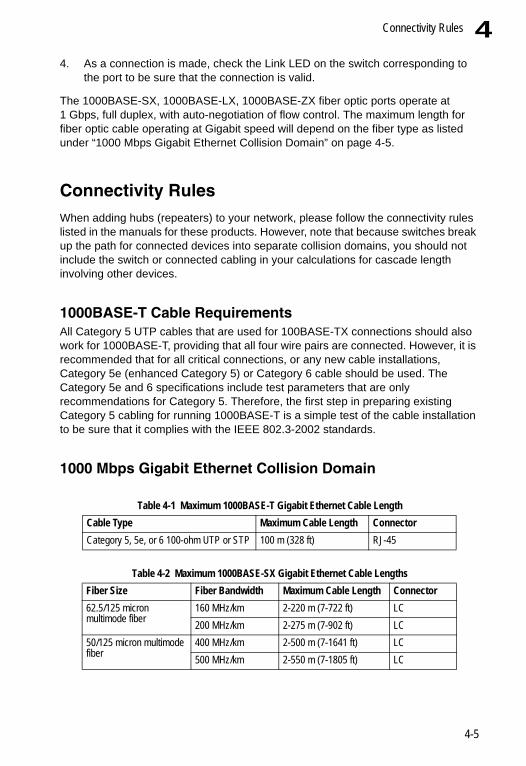
4. As a connection is made, check the Link LED on the switch corresponding tothe port to be sure that the connection is valid.
The 1000BASE-SX, 1000BASE-LX, 1000BASE-ZX fiber optic ports operate at 1 Gbps, full duplex, with auto-negotiation of flow control. The maximum length for fiber optic cable operating at Gigabit speed will depend on the fiber type as listed under “1000 Mbps Gigabit Ethernet Collision Domain” on page 4-5.
Connectivity RulesWhen adding hubs (repeaters) to your network, please follow the connectivity rules listed in the manuals for these products. However, note that because switches break up the path for connected devices into separate collision domains, you should not include the switch or connected cabling in your calculations for cascade length involving other devices.
1000BASE-T Cable RequirementsAll Category 5 UTP cables that are used for 100BASE-TX connections should also work for 1000BASE-T, providing that all four wire pairs are connected. However, it is recommended that for all critical connections, or any new cable installations, Category 5e (enhanced Category 5) or Category 6 cable should be used. The Category 5e and 6 specifications include test parameters that are only recommendations for Category 5. Therefore, the first step in preparing existing Category 5 cabling for running 1000BASE-T is a simple test of the cable installation to be sure that it complies with the IEEE 802.3-2002 standards.
1000 Mbps Gigabit Ethernet Collision Domain
Table 4-1 Maximum 1000BASE-T Gigabit Ethernet Cable LengthCable Type Maximum Cable Length ConnectorCategory 5, 5e, or 6 100-ohm UTP or STP 100 m (328 ft) RJ-45
Table 4-2 Maximum 1000BASE-SX Gigabit Ethernet Cable LengthsFiber Size Fiber Bandwidth Maximum Cable Length Connector62.5/125 micron multimode fiber
160 MHz/km 2-220 m (7-722 ft) LC200 MHz/km 2-275 m (7-902 ft) LC
50/125 micron multimode fiber
400 MHz/km 2-500 m (7-1641 ft) LC500 MHz/km 2-550 m (7-1805 ft) LC
4-5

Making Network Connections4
100 Mbps Fast Ethernet Collision Domain
10 Mbps Ethernet Collision Domain
Cable Labeling and Connection RecordsWhen planning a network installation, it is essential to label the opposing ends of cables and to record where each cable is connected. Doing so will enable you to easily locate inter-connected devices, isolate faults and change your topology without need for unnecessary time consumption.
To best manage the physical implementations of your network, follow these guidelines:
• Clearly label the opposing ends of each cable.• Using your building’s floor plans, draw a map of the location of all
network-connected equipment. For each piece of equipment, identify the devices to which it is connected.
• Note the length of each cable and the maximum cable length supported by the switch ports.
• For ease of understanding, use a location-based key when assigning prefixes to your cable labeling.
• Use sequential numbers for cables that originate from the same equipment.
Table 4-3 Maximum 1000BASE-LX Gigabit Ethernet Cable LengthFiber Size Fiber Bandwidth Maximum Cable Length Connector9/125 micron single-mode fiber
N/A 2 m - 10 km (7 ft - 6.4 miles) LC
Fiber Size Fiber Bandwidth Maximum Cable Length ConnectorN/A 2 m - 70 km (7 ft - 43.5 miles) LC
Table 4-5 Maximum Fast Ethernet Cable LengthType Cable Type Max. Cable Length Connector100BASE-TX Category 5 or better 100-ohm UTP or STP 100 m (328 ft) RJ-45
Table 4-6 Maximum Ethernet Cable LengthType Cable Type Max. Cable Length Connector10BASE-T Category 3 or better 100-ohm UTP 100 m (328 ft) RJ-45
Table 4-4 Maximum 1000BASE-ZX Gigabit Ethernet Cable Length
4-6

Cable Labeling and Connection Records 4
• Differentiate between racks by naming accordingly.• Label each separate piece of equipment.• Display a copy of your equipment map, including keys to all abbreviations at eachequipment rack.
4-7

Making Network Connections4
4-8

Appendix A: Troubleshooting
Diagnosing Switch Indicators
Diagnosing Power Problems with the LEDsThe Power and RPU LEDs work in combination to indicate power status as follows.
Table A-1 Troubleshooting ChartSymptom ActionPWR LED is Off • Check connections between the switch, the power cord and the wall
outlet.• Contact your dealer for assistance
PWR LED is Amber • Internal power supply has failed. Contact your local dealer for assistance.
Diag LED is Amber • Power cycle the switch to try and clear the condition• If the condition does not clear, contact your dealer for assistance
Stack Master LED is Flashing Amber
• The stack has not completed its initial configuration. Wait a few minutes for the process to complete.
• If flashing continues, check that the Master Select button is pressed in on only one switch.
• Check that all stacking cables are properly connected.Link LED is Off • Verify that the switch and attached device are powered on.
• Be sure the cable is plugged into both the switch and corresponding device.
• If the switch is installed in a rack, check the connections to the punch-down block and patch panel.
• Verify that the proper cable type is used and its length does not exceed specified limits.
• Check the adapter on the attached device and cable connections for possible defects. Replace the defective adapter or cable if necessary.
Table A-2 Power/RPU LEDsPower LED RPU LED StatusGreen Green Internal power functioning normally; RPU is present.Green Off Internal power functioning normally; RPU not plugged in or faulty.Off Off Both internal power and RPU unplugged or not functioning.
A-1

TroubleshootingA
Power and Cooling ProblemsIf the power indicator does not turn on when the power cord is plugged in, you may have a problem with the power outlet, power cord, or internal power supply. However, if the unit powers off after running for a while, check for loose power connections, power losses or surges at the power outlet. If you still cannot isolate the problem, the internal power supply may be defective.InstallationVerify that all system components have been properly installed. If one or more components appear to be malfunctioning (such as the power cord or network cabling), test them in an alternate environment where you are sure that all the other components are functioning properly.
In-Band AccessYou can access the management agent in the switch from anywhere within the attached network using Telnet, a web browser, or other network management software tools. However, you must first configure the switch with a valid IP address, subnet mask, and default gateway. If you have trouble establishing a link to the management agent, check to see if you have a valid network connection. Then verify that you entered the correct IP address. Also, be sure the port through which you are connecting to the switch has not been disabled. If it has not been disabled, then check the network cabling that runs between your remote location and the switch.
Note: The management agent accepts up to four simultaneous Telnet sessions. If the maximum number of sessions already exists, an additional Telnet connection will not be able to log into the system.
Stack TroubleshootingIf a stack fails to initialize or function, first check the following items:
• Check that all stacking cables are properly connected.• Check if any stacking cables appear damaged.• Check that the Master select button is pressed in on only one unit in the stack.• Check that each unit has the stacking ports enabled (the Stack button pushed out).• Check that all switches in the stack are powered on.
After checking all items, reboot all the switches in the stack.
A-2

Appendix B: Cables
Twisted-Pair Cable and Pin AssignmentsFor 10/100BASE-TX connections, the twisted-pair cable must have two pairs of wires. For 1000BASE-T connections the twisted-pair cable must have four pairs of wires. Each wire pair is identified by two different colors. For example, one wire might be green and the other, green with white stripes. Also, an RJ-45 connector must be attached to both ends of the cable.
Caution: DO NOT plug a phone jack connector into any RJ-45 port. Use only twisted-pair cables with RJ-45 connectors that conform with FCC standards.
Caution: Each wire pair must be attached to the RJ-45 connectors in a specific orientation. (See “Cabling Guidelines” on page 4-1 for an explanation.)
The figure below illustrates how the pins on the RJ-45 connector are numbered. Be sure to hold the connectors in the same orientation when attaching the wires to the pins.
Figure B-1 RJ-45 Connector Pin Numbers
10BASE-T/100BASE-TX Pin AssignmentsUse unshielded twisted-pair (UTP) or shielded twisted-pair (STP) cable for RJ-45 connections: 100-ohm Category 3 or better cable for 10 Mbps connections, or 100-ohm Category 5 or better cable for 100 Mbps connections. Also be sure that the length of any twisted-pair connection does not exceed 100 meters (328 feet).
The RJ-45 ports on the switch base unit support automatic MDI/MDI-X operation, so you can use straight-through cables for all network connections to PCs or servers, or to other switches or hubs. In straight-through cable, pins 1, 2, 3, and 6, at one end of the cable, are connected straight through to pins 1, 2, 3, and 6 at the other end of the cable. When using any RJ-45 port on this switch, you can use either straight-through or crossover cable.
811
8
B-1

CablesB
Straight-Through WiringIf the twisted-pair cable is to join two ports and only one of the ports has an internal crossover (MDI-X), the two pairs of wires must be straight-through. (When auto-negotiation is enabled for any RJ-45 port on this switch, you can use either straight-through or crossover cable to connect to any device type.)
You must connect all four wire pairs as shown in the following diagram to support Gigabit Ethernet.
Figure B-2 Straight-through Wiring
Crossover WiringIf the twisted-pair cable is to join two ports and either both ports are labeled with an “X” (MDI-X) or neither port is labeled with an “X” (MDI), a crossover must be implemented in the wiring. (When auto-negotiation is enabled for any RJ-45 port on this switch, you can use either straight-through or crossover cable to connect to any device type.)
Table B-1 10/100BASE-TX MDI and MDI-X Port PinoutsPin MDI Signal Name MDI-X Signal Name
1 Transmit Data plus (TD+) Receive Data plus (RD+)2 Transmit Data minus (TD-) Receive Data minus (RD-)3 Receive Data plus (RD+) Transmit Data plus (TD+)6 Receive Data minus (RD-) Transmit Data minus (TD-)4,5,7,8 Not used Not usedNote: The “+” and “-” signs represent the polarity of the wires that make
up each wire pair.
White/Orange Stripe
Orange
White/Green Stripe
Green
1
2
3
4
5
6
7
8
1
2
3
4
5
6
7
8
EIA/TIA 568B RJ-45 Wiring Standard
10/100BASE-TX Straight-through Cable
End A End BBlue
White/Blue Stripe
Brown
White/Brown Stripe
B-2

Twisted-Pair Cable and Pin AssignmentsB
You must connect all four wire pairs as shown in the following diagram to support Gigabit Ethernet.Figure B-3 Crossover Wiring
1000BASE-T Pin AssignmentsAll 1000BASE-T ports support automatic MDI/MDI-X operation, so you can use straight-through cables for all network connections to PCs or servers, or to other switches or hubs.
The table below shows the 1000BASE-T MDI and MDI-X port pinouts. These ports require that all four pairs of wires be connected. Note that for 1000BASE-T operation, all four pairs of wires are used for both transmit and receive.
Use 100-ohm Category 5, 5e or 6 unshielded twisted-pair (UTP) or shielded twisted-pair (STP) cable for 1000BASE-T connections. Also be sure that the length of any twisted-pair connection does not exceed 100 meters (328 feet).
Table B-2 1000BASE-T MDI and MDI-X Port PinoutsPin MDI Signal Name MDI-X Signal Name1 Bi-directional Data One Plus (BI_D1+) Bi-directional Data Two Plus (BI_D2+)
2 Bi-directional Data One Minus (BI_D1-) Bi-directional Data Two Minus (BI_D2-)
3 Bi-directional Data Two Plus (BI_D2+) Bi-directional Data One Plus (BI_D1+)
4 Bi-directional Data Three Plus (BI_D3+) Bi-directional Data Four Plus (BI_D4+)
5 Bi-directional Data Three Minus (BI_D3-) Bi-directional Data Four Minus (BI_D4-)
6 Bi-directional Data Two Minus (BI_D2-) Bi-directional Data One Minus (BI_D1-)
7 Bi-directional Data Four Plus (BI_D4+) Bi-directional Data Three Plus (BI_D3+)
8 Bi-directional Data Four Minus (BI_D4-) Bi-directional Data Three Minus (BI_D3-)
White/Orange Stripe
Orange
White/Green Stripe1
2
3
4
5
6
7
8
1
2
3
4
5
6
7
8
EIA/TIA 568B RJ-45 Wiring Standard
10/100BASE-TX Crossover Cable
End A End B
Green
Blue
White/Blue Stripe
Brown
White/Brown Stripe
B-3

CablesB
Cable Testing for Existing Category 5 CableInstalled Category 5 cabling must pass tests for Attenuation, Near-End Crosstalk (NEXT), and Far-End Crosstalk (FEXT). This cable testing information is specified in the ANSI/TIA/EIA-TSB-67 standard. Additionally, cables must also pass test parameters for Return Loss and Equal-Level Far-End Crosstalk (ELFEXT). These tests are specified in the ANSI/TIA/EIA-TSB-95 Bulletin, “The Additional Transmission Performance Guidelines for 100 Ohm 4-Pair Category 5 Cabling.”Note that when testing your cable installation, be sure to include all patch cables between switches and end devices.
Adjusting Existing Category 5 Cabling to Run 1000BASE-TIf your existing Category 5 installation does not meet one of the test parameters for 1000BASE-T, there are basically three measures that can be applied to try and correct the problem:
1. Replace any Category 5 patch cables with high-performance Category 5e or Category 6 cables.
2. Reduce the number of connectors used in the link.3. Reconnect some of the connectors in the link.
Fiber StandardsThe current TIA (Telecommunications Industry Association) 568-A specification on optical fiber cabling consists of one recognized cable type for horizontal subsystems and two cable types for backbone subsystems.
Horizontal 62.5/125 micron multimode (two fibers per outlet).Backbone 62.5/125 micron multimode or single-mode.
TIA 568-B will allow the use of 50/125 micron multimode optical fiber in both the horizontal and backbone in addition to the types listed above. All optical fiber components and installation practices must meet applicable building and safety codes.
B-4
Appendix C: Specifications
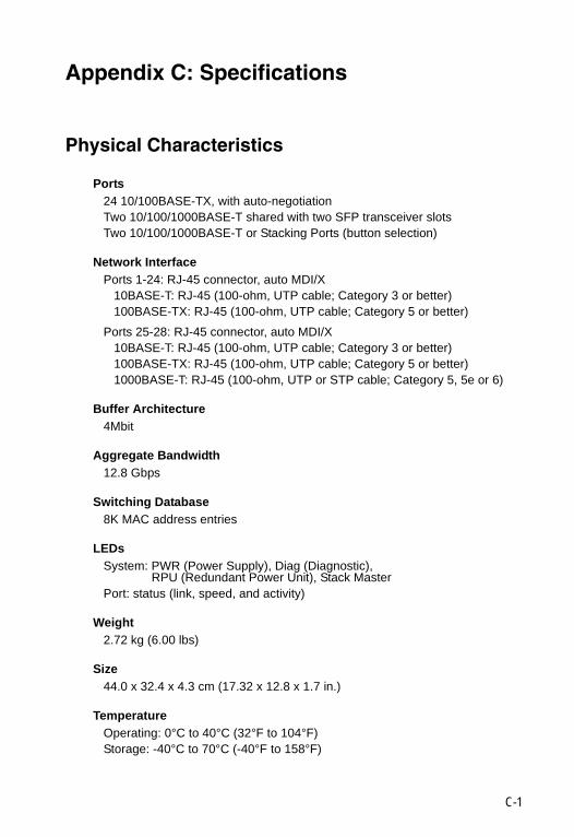
Physical Characteristics
Ports24 10/100BASE-TX, with auto-negotiationTwo 10/100/1000BASE-T shared with two SFP transceiver slotsTwo 10/100/1000BASE-T or Stacking Ports (button selection)
Network InterfacePorts 1-24: RJ-45 connector, auto MDI/X
10BASE-T: RJ-45 (100-ohm, UTP cable; Category 3 or better)100BASE-TX: RJ-45 (100-ohm, UTP cable; Category 5 or better)
Ports 25-28: RJ-45 connector, auto MDI/X10BASE-T: RJ-45 (100-ohm, UTP cable; Category 3 or better)100BASE-TX: RJ-45 (100-ohm, UTP cable; Category 5 or better)1000BASE-T: RJ-45 (100-ohm, UTP or STP cable; Category 5, 5e or 6)
Buffer Architecture4Mbit
Aggregate Bandwidth12.8 Gbps
Switching Database8K MAC address entries
LEDs System: PWR (Power Supply), Diag (Diagnostic),
RPU (Redundant Power Unit), Stack MasterPort: status (link, speed, and activity)
Weight2.72 kg (6.00 lbs)
Size44.0 x 32.4 x 4.3 cm (17.32 x 12.8 x 1.7 in.)
TemperatureOperating: 0°C to 40°C (32°F to 104°F)Storage: -40°C to 70°C (-40°F to 158°F)
C-1

SpecificationsC
HumidityOperating: 5% to 95% (non-condensing)
Power SupplyInternal, auto-ranging transformer: 100 to 240 VAC, 50 to 60 HzExternal, supports connection for redundant power supply
Power Consumption25 Watts maximum
Maximum Current1.5 A @ 100 VAC 0.6 A @ 240 VAC
Switch Features
Forwarding ModeStore-and-forward
ThroughputWire speed
Flow ControlFull Duplex: IEEE 802.3xHalf Duplex: Back pressure
Management Features
In-Band ManagementSSH, Telnet, SNMP, RMON (4-group), or HTTP
Out-of-Band ManagementRS-232 DB-9 console port
Software LoadingTFTP in-band, or XModem out-of-band
C-2

StandardsC
StandardsIEEE 802.3-2002 Ethernet, Fast Ethernet, Gigabit EthernetFull-duplex flow controlLink Aggregation Control Protocol
IEEE 802.1D Spanning Tree ProtocolIEEE 802.1w Rapid Spanning Tree ProtocolISO/IEC 8802-3
Compliances
EmissionsEN55022 (CISPR 22) Class AEN 61000-3-2/3FCC Class A
ImmunityEN 61000-4-2/3/4/5/6/8/11
Safety(EN60950)
C-3

SpecificationsC
C-4

Glossary
10BASE-TIEEE 802.3 specification for 10 Mbps Ethernet over two pairs of Category 3, 4, or 5 UTP cable.
100BASE-FXIEEE 802.3 specification for 100 Mbps Ethernet over two strands of 50/125, 62.5/125 micron, or 9/125 micron core fiber cable.
100BASE-TXIEEE 802.3u specification for 100 Mbps Ethernet over two pairs of Category 5 UTP cable.
1000BASE-LXIEEE 802.3z specification for Gigabit Ethernet over two strands of 50/125, 62.5/125 or 9/125 micron core fiber cable.
1000BASE-SXIEEE 802.3z specification for Gigabit Ethernet over two strands of 50/125 or 62.5/125 micron core fiber cable.
1000BASE-TIEEE 802.3ab specification for Gigabit Ethernet over 100-ohm Category 5, 5e or 6 twisted-pair cable (using all four wire pairs).
Auto-NegotiationSignalling method allowing each node to select its optimum operational mode (e.g., speed and duplex mode) based on the capabilities of the node to which it is connected.
BandwidthThe difference between the highest and lowest frequencies available for network signals. Also synonymous with wire speed, the actual speed of the data transmission along the cable.
CollisionA condition in which packets transmitted over the cable interfere with each other. Their interference makes both signals unintelligible.
Collision DomainSingle CSMA/CD LAN segment.
Glossary-1
Glossary
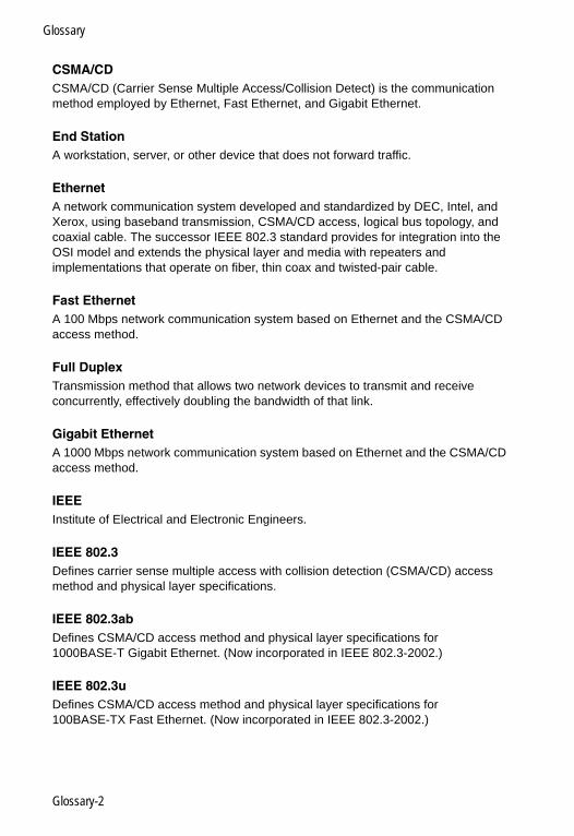
CSMA/CDCSMA/CD (Carrier Sense Multiple Access/Collision Detect) is the communication method employed by Ethernet, Fast Ethernet, and Gigabit Ethernet.
End StationA workstation, server, or other device that does not forward traffic.
EthernetA network communication system developed and standardized by DEC, Intel, and Xerox, using baseband transmission, CSMA/CD access, logical bus topology, and coaxial cable. The successor IEEE 802.3 standard provides for integration into the OSI model and extends the physical layer and media with repeaters and implementations that operate on fiber, thin coax and twisted-pair cable.
Fast EthernetA 100 Mbps network communication system based on Ethernet and the CSMA/CD access method.
Full DuplexTransmission method that allows two network devices to transmit and receive concurrently, effectively doubling the bandwidth of that link.
Gigabit EthernetA 1000 Mbps network communication system based on Ethernet and the CSMA/CD access method.
IEEEInstitute of Electrical and Electronic Engineers.
IEEE 802.3Defines carrier sense multiple access with collision detection (CSMA/CD) access method and physical layer specifications.
IEEE 802.3abDefines CSMA/CD access method and physical layer specifications for 1000BASE-T Gigabit Ethernet. (Now incorporated in IEEE 802.3-2002.)
IEEE 802.3uDefines CSMA/CD access method and physical layer specifications for 100BASE-TX Fast Ethernet. (Now incorporated in IEEE 802.3-2002.)
Glossary-2
Glossary
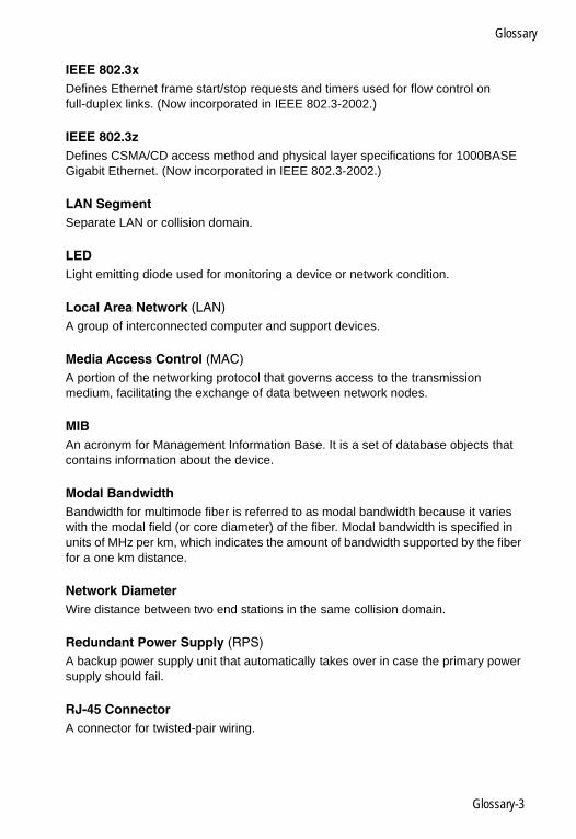
IEEE 802.3xDefines Ethernet frame start/stop requests and timers used for flow control on full-duplex links. (Now incorporated in IEEE 802.3-2002.)
IEEE 802.3zDefines CSMA/CD access method and physical layer specifications for 1000BASE Gigabit Ethernet. (Now incorporated in IEEE 802.3-2002.)
LAN SegmentSeparate LAN or collision domain.
LEDLight emitting diode used for monitoring a device or network condition.
Local Area Network (LAN) A group of interconnected computer and support devices.
Media Access Control (MAC)A portion of the networking protocol that governs access to the transmission medium, facilitating the exchange of data between network nodes.
MIBAn acronym for Management Information Base. It is a set of database objects that contains information about the device.
Modal BandwidthBandwidth for multimode fiber is referred to as modal bandwidth because it varies with the modal field (or core diameter) of the fiber. Modal bandwidth is specified in units of MHz per km, which indicates the amount of bandwidth supported by the fiber for a one km distance.
Network DiameterWire distance between two end stations in the same collision domain.
Redundant Power Supply (RPS)A backup power supply unit that automatically takes over in case the primary power supply should fail.
RJ-45 ConnectorA connector for twisted-pair wiring.
Glossary-3

Glossary
Switched PortsPorts that are on separate collision domains or LAN segments.
TIATelecommunications Industry Association
Transmission Control Protocol/Internet Protocol (TCP/IP)Protocol suite that includes TCP as the primary transport protocol, and IP as the network layer protocol.
UTPUnshielded twisted-pair cable.
Virtual LAN (VLAN)A Virtual LAN is a collection of network nodes that share the same collision domain regardless of their physical location or connection point in the network. A VLAN serves as a logical workgroup with no physical barriers, allowing users to share information and resources as though located on the same LAN.
Glossary-4
Index
Numerics10 Mbps connectivity rules 4-6100 Mbps connectivity rules 4-61000 Mbps connectivity rules 4-51000BASE-LX fiber cable length 4-61000BASE-SX fiber cable length 4-61000BASE-ZX fiber cable length 4-51000BASE-T
pin assignments B-3ports 1-3
100BASE-TXcable length 4-6ports 1-2
10BASE-Tcable length 4-6ports 1-2
Aadhesive feet, attaching 3-5air flow requirements 3-1applications
central wiring closet 2-3collapsed backbone 2-2remote connections with fiber 2-4VLAN connections 2-5
Bbrackets, attaching 3-3buffer size C-1buffers, saturation of 1-2
Ccable
Ethernet cable compatibility 3-1fiber standards B-4labeling and connection records 4-6lengths 4-5
cleaning fiber terminators 4-4compliances
EMC C-3connectivity rules
10 Mbps 4-6100 Mbps 4-6
1000 Mbps 4-5console port, pin assignments 3-8contents of package 3-2cooling problems A-2cord sets, international 3-8
Ddesktop mounting 3-5device connections 4-1
Eelectrical interference, avoiding 3-1equipment checklist 3-2Ethernet connectivity rules 4-6
FFast Ethernet connectivity rules 4-6features C-2
management 1-7switch 1-6
fiber cables 4-4flow control, IEEE 802.3x 1-2front panel of switch 1-1full duplex connectivity 2-1
GGigabit Ethernet cable lengths 4-5grounding for racks 3-3
IIEEE 802.3x flow control 1-2indicators, LED 1-4installation
connecting devices to the switch 4-2desktop or shelf mounting 3-5network wiring connections 4-2port connections 4-1, 4-4power requirements 3-1problems A-2rack mounting 3-3site requirements 3-1
Index-1
Index
Llaser safety 4-4LC port connections 4-4LED indicators
Diag 1-5Power 1-5problems A-1Stack 1-5
location requirements 3-1
Mmanagement
agent 1-2features 1-7, C-2out-of-band 1-2SNMP 1-2web-based 1-2
Maximum Fast Ethernet Cable Distance 4-6
mounting the switchin a rack 3-3on a desktop or shelf 3-5
multimode fiber optic cables 4-4
Nnetwork
connections 4-1, 4-4examples 2-2
Oout-of-band management 1-2
Ppackage contents 3-2pin assignments B-1
1000BASE-T B-310BASE-T/100BASE-TX B-1console port 3-8DB-9 3-8
port saturation 1-2ports, connecting to 4-1, 4-4power, connecting to 3-8problems, troubleshooting A-1
Rrack mounting 3-3rear panel of switch 1-1rear panel receptacles 1-6RJ-45 port
connections 4-1pinouts B-3
RMON 1-2RS-232 port 1-2rubber foot pads, attaching 3-5
Sscrews for rack mounting 3-2serial
cable 1-2port 1-2
single-mode fiber optic cables 4-4site selelction 3-1SNMP agent 1-2specifications
compliances C-2environmental C-1physical C-1power C-2
standardscompliance C-2IEEE C-3
status LEDs 1-4surge suppressor, using 3-1switch architecture 1-2switching
introduction to 2-1method 1-2
TTelnet A-2temperature within a rack 3-3troubleshooting
in-band access A-2power and cooling problems A-2switch indicators A-1
twisted-pair connections 4-1
VVLANs
Index-2

Index
tagging 2-5
Wweb-based management 1-2
Index-3

Index
Index-4


GSW-2692E072006-JC-R01