ifc 100ifc 100ifc 100ifc 100 …1 safety instructions 6 ifc 100 07/2014 - 4000041005 - ma ifc 100...
TRANSCRIPT
Signal converter for electromagnetic flowmeters
Electronic revision:ER 3.1.x
IFC 100IFC 100IFC 100IFC 100 HandbookHandbookHandbookHandbook
© KROHNE 07/2014 - 4000041005 - MA IFC 100 R05 en
The documentation is only complete when used in combination with the relevant documentation for the flow sensor.

All rights reserved. It is prohibited to reproduce this documentation, or any part thereof, without
the prior written authorisation of KROHNE Messtechnik GmbH.
Subject to change without notice.
2 www.krohne.com 07/2014 - 4000041005 - MA IFC 100 R05 en
Copyright 2014 by
KROHNE Messtechnik GmbH - Ludwig-Krohne-Str. 5 - 47058 Duisburg (Germany)
: IMPRINT :::::::::::::::::::::::::::::::::::::::
CONTENTS
3www.krohne.com07/2014 - 4000041005 - MA IFC 100 R05 en
IFC 100
1 Safety instructions 6
1.1 Software history ............................................................................................................... 61.2 Intended use ..................................................................................................................... 71.3 Certifications .................................................................................................................... 71.4 Safety instructions from the manufacturer ..................................................................... 8
1.4.1 Copyright and data protection ................................................................................................ 81.4.2 Disclaimer ............................................................................................................................... 81.4.3 Product liability and warranty ................................................................................................ 91.4.4 Information concerning the documentation........................................................................... 91.4.5 Warnings and symbols used................................................................................................. 10
1.5 Safety instructions for the operator............................................................................... 10
2 Device description 11
2.1 Scope of delivery............................................................................................................. 112.2 Device description .......................................................................................................... 122.3 Nameplates .................................................................................................................... 13
2.3.1 Nameplate (example)............................................................................................................ 13
3 Installation 14
3.1 General notes on installation ......................................................................................... 143.2 Storage ........................................................................................................................... 143.3 Transport ........................................................................................................................ 143.4 Installation specifications .............................................................................................. 143.5 Mounting of the compact version................................................................................... 153.6 Mounting the wall-mounted housing, remote version .................................................. 15
3.6.1 Wall mounting ....................................................................................................................... 15
4 Electrical connections 17
4.1 Safety instructions.......................................................................................................... 174.2 Important notes on electrical connection...................................................................... 174.3 Electrical cables for remote device versions, notes...................................................... 18
4.3.1 Notes on signal cable A ........................................................................................................ 184.3.2 Notes on field current cable C.............................................................................................. 184.3.3 Requirements for signal cables provided by the customer ................................................. 19
4.4 Preparing the signal and field current cables ............................................................... 204.4.1 Signal cable A (type DS 300), construction........................................................................... 204.4.2 Preparing signal cable A, connection to signal converter ................................................... 214.4.3 Length of signal cable A........................................................................................................ 224.4.4 Preparing field current cable C, connection to signal converter......................................... 234.4.5 Preparing signal cable A, connection to measuring sensor ................................................ 254.4.6 Preparing field current cable C, connection to measuring sensor ..................................... 26
4.5 Connecting the signal and field current cables............................................................. 274.5.1 Connecting the signal and field current cables to the signal converter, remote version... 284.5.2 Connection diagram for signal and field current cable ....................................................... 30
4.6 Grounding the measuring sensor .................................................................................. 314.6.1 Classical method................................................................................................................... 31
CONTENTS
4 www.krohne.com 07/2014 - 4000041005 - MA IFC 100 R05 en
IFC 100
4.7 Connecting the power supply......................................................................................... 324.8 Inputs and outputs, overview ......................................................................................... 34
4.8.1 Description of the CG number .............................................................................................. 344.8.2 Fixed, non-alterable output versions ................................................................................... 34
4.9 Description of the inputs and outputs............................................................................ 364.9.1 Current output ...................................................................................................................... 364.9.2 Pulse output and frequency output ...................................................................................... 374.9.3 Status output and limit switch .............................................................................................. 384.9.4 Control input ......................................................................................................................... 39
4.10 Electrical connection of the outputs ............................................................................ 404.10.1 Electrical connection of the outputs................................................................................... 404.10.2 Laying electrical cables correctly....................................................................................... 41
4.11 Connection diagrams of outputs .................................................................................. 414.11.1 Important notes................................................................................................................... 414.11.2 Description of the electrical symbols................................................................................. 424.11.3 Basic outputs....................................................................................................................... 434.11.4 Ex i outputs.......................................................................................................................... 474.11.5 HART® connection .............................................................................................................. 49
5 Start-up 50
5.1 Switching on the power .................................................................................................. 505.2 Starting the signal converter ......................................................................................... 50
6 Operation 51
6.1 Display and operating elements .................................................................................... 516.1.1 Display in measuring mode with 2 or 3 measured values ................................................... 526.1.2 Display for selection of sub-menu and functions, 3 lines.................................................... 526.1.3 Display when setting parameters, 4 lines ............................................................................ 536.1.4 Display when previewing parameters, 4 lines...................................................................... 53
6.2 Menu structure ............................................................................................................... 546.3 Function tables ............................................................................................................... 56
6.3.1 Menu A, quick setup.............................................................................................................. 566.3.2 Menu B, test .......................................................................................................................... 586.3.3 Menu C, setup ....................................................................................................................... 606.3.4 Set free units......................................................................................................................... 76
6.4 Description of functions ................................................................................................. 766.4.1 Reset counter in the menu "quick setup" ............................................................................ 766.4.2 Deleting error messages in the menu "quick setup"........................................................... 77
6.5 Status messages and diagnostic information................................................................ 77
7 Service 82
7.1 Spare parts availability................................................................................................... 827.2 Availability of services .................................................................................................... 827.3 Returning the device to the manufacturer..................................................................... 82
7.3.1 General information.............................................................................................................. 827.3.2 Form (for copying) to accompany a returned device............................................................ 83
7.4 Disposal .......................................................................................................................... 83
CONTENTS
5www.krohne.com07/2014 - 4000041005 - MA IFC 100 R05 en
IFC 100
8 Technical data 84
8.1 Measuring principle........................................................................................................ 848.2 Technical data................................................................................................................. 858.3 Dimensions and weights ................................................................................................ 94
8.3.1 Housing ................................................................................................................................. 948.3.2 Mounting plate, wall-mounted version ................................................................................ 97
8.4 Flow tables ..................................................................................................................... 988.5 Measuring accuracy ..................................................................................................... 100
9 Description of HART interface 101
9.1 General description ...................................................................................................... 1019.2 Software history ........................................................................................................... 1019.3 Connection variants...................................................................................................... 102
9.3.1 Point-to-Point connection - analogue / digital mode......................................................... 1039.3.2 Multi-Drop connection (2-wire connection) ....................................................................... 1049.3.3 Multi-Drop connection (3-wire connection) ....................................................................... 105
9.4 Outputs and HART® dynamic variables and device variables ..................................... 1069.5 Parameter for the basic configuration......................................................................... 1079.6 Field Communicator 375/475 (FC 375/475) ................................................................. 108
9.6.1 Installation .......................................................................................................................... 1089.6.2 Operation............................................................................................................................. 1089.6.3 Parameter for the basic configuration ............................................................................... 108
9.7 Asset Management Solutions (AMS)............................................................................ 1099.7.1 Installation .......................................................................................................................... 1099.7.2 Operation............................................................................................................................. 1099.7.3 Parameter for the basic configuration ............................................................................... 109
9.8 Field Device Manager (FDM) ........................................................................................ 1109.8.1 Installation .......................................................................................................................... 1109.8.2 Operation............................................................................................................................. 110
9.9 Process Device Manager (PDM)................................................................................... 1109.9.1 Installation .......................................................................................................................... 1109.9.2 Operation............................................................................................................................. 1119.9.3 Parameter for the basic configuration ............................................................................... 111
9.10 Field Device Tool / Device Type Manager (FDT / DTM) .............................................. 1129.10.1 Installation ........................................................................................................................ 1129.10.2 Operation........................................................................................................................... 112
9.11 Appendix A: HART® menu tree for Basic-DD ............................................................ 1129.11.1 Overview Basic-DD menu tree (positions in menu tree).................................................. 1139.11.2 Basic-DD menu tree (details for settings)........................................................................ 114
9.12 Appendix B: HART® menu tree for AMS .................................................................... 1179.12.1 Overview AMS menu tree (positions in menu tree) .......................................................... 1179.12.2 AMS menu tree (details for settings)................................................................................ 118
9.13 Appendix C: HART® menu tree for PDM.................................................................... 1229.13.1 Overview PDM menu tree (positions in menu tree).......................................................... 1229.13.2 PDM menu tree (details for settings) ............................................................................... 124

1 SAFETY INSTRUCTIONS
6
IFC 100
www.krohne.com 07/2014 - 4000041005 - MA IFC 100 R05 en
1.1 Software history
The "Electronic Revision" (ER) is consulted to document the revision status of electronic equipment according to NE 53 for all GDC devices. It is easy to see from the ER whether troubleshooting or larger changes in the electronic equipment have taken place and how that has affected the compatibility.
Changes and effect on compatibility
1 Downwards compatible changes and fault repair with no effect on operation (e.g. spelling mistakes on display)
2-_ Downwards compatible hardware and/or software change of interfaces:
H HART®
P PROFIBUS
F Foundation Fieldbus
M Modbus
X all interfaces
3-_ Downwards compatible hardware and/or software change of inputs and outputs:
I Current output
F, P Frequency / pulse output
S Status output
C Control input
CI Current input
X all inputs and outputs
4 Downwards compatible changes with new functions
5 Incompatible changes, i.e. electronic equipment must be changed.
INFORMATION!In the table below, "x" is a placeholder for possible multi-digit alphanumeric combinations, depending on the available version.
Release date Electronic Revision Changes and compatibility
Documentation
2007-12-11 ER 2.0.0(SW.REV. 2.00 (2.00))
- -
2008-02-29 ER 2.0.1(SW.REV. 2.00 (2.00))
1 MA IFC 100 R03
2008-05-07 ER 2.0.2(SW.REV. 2.00 (2.00))
1 MA IFC 100 R04
2008-06-27 ER 2.0.3(SW.REV. 2.00 (2.00))
1 MA IFC 100 R04
2010-01-04 ER 2.0.4(SW.REV. 2.00 (2.00))
1 MA IFC 100 R04
2010-01-04 ER 2.1.0(SW.REV. 2.10 (3.00))
1; 2-H MA IFC 100 R04
2010-07-08 ER 2.1.1(SW.REV. 2.11 (3.00))
1 MA IFC 100 R04
2011-12-12 ER 3.0.0(SW.REV. 3.00 (4.00))
1; 2-X; 3-X, 5-S 1 MA IFC 100 R05
2013-04-26 ER 3.0.1 1 MA IFC 100 R05
SAFETY INSTRUCTIONS 1
7
IFC 100
www.krohne.com07/2014 - 4000041005 - MA IFC 100 R05 en
1.2 Intended use
The electromagnetic flowmeters are designed exclusively to measure the flow and conductivity of electrically conductive, liquid media.
1.3 Certifications
The device fulfils the statutory requirements of the following EC directives:• Low Voltage Directive 2006/95/EC• EMC Directive 2004/108/EC
as well as
• EN 61010• EMC specification acc. to EN 61326/A1• NAMUR recommendations NE 21 and NE 43
The manufacturer certifies successful testing of the product by applying the CE marking.
2014-02-14 ER 3.0.2 1 MA IFC 100 R05
2014-08-01 ER 3.1.0 1; 2-H; 2-M; 3-F; 3-P; 3-C
MA IFC 100 R05
1 Incompatible change on status output: de-energised status reversed
Release date Electronic Revision Changes and compatibility
Documentation
DANGER!For devices used in hazardous areas, additional safety notes apply; please refer to the Ex documentation.
WARNING!If the device is not used according to the operating conditions (refer to chapter "Technical data"), the intended protection could be affected.
CE marking
DANGER!For devices used in hazardous areas, additional safety notes apply; please refer to the Ex documentation.

1 SAFETY INSTRUCTIONS
8
IFC 100
www.krohne.com 07/2014 - 4000041005 - MA IFC 100 R05 en
1.4 Safety instructions from the manufacturer
1.4.1 Copyright and data protection
The contents of this document have been created with great care. Nevertheless, we provide no guarantee that the contents are correct, complete or up-to-date.
The contents and works in this document are subject to copyright. Contributions from third parties are identified as such. Reproduction, processing, dissemination and any type of use beyond what is permitted under copyright requires written authorisation from the respective author and/or the manufacturer.
The manufacturer tries always to observe the copyrights of others, and to draw on works created in-house or works in the public domain.
The collection of personal data (such as names, street addresses or e-mail addresses) in the manufacturer's documents is always on a voluntary basis whenever possible. Whenever feasible, it is always possible to make use of the offerings and services without providing any personal data.
We draw your attention to the fact that data transmission over the Internet (e.g. when communicating by e-mail) may involve gaps in security. It is not possible to protect such data completely against access by third parties.
We hereby expressly prohibit the use of the contact data published as part of our duty to publish an imprint for the purpose of sending us any advertising or informational materials that we have not expressly requested.
1.4.2 Disclaimer
The manufacturer will not be liable for any damage of any kind by using its product, including, but not limited to direct, indirect or incidental and consequential damages.
This disclaimer does not apply in case the manufacturer has acted on purpose or with gross negligence. In the event any applicable law does not allow such limitations on implied warranties or the exclusion of limitation of certain damages, you may, if such law applies to you, not be subject to some or all of the above disclaimer, exclusions or limitations.
Any product purchased from the manufacturer is warranted in accordance with the relevant product documentation and our Terms and Conditions of Sale.
The manufacturer reserves the right to alter the content of its documents, including this disclaimer in any way, at any time, for any reason, without prior notification, and will not be liable in any way for possible consequences of such changes.
SAFETY INSTRUCTIONS 1
9
IFC 100
www.krohne.com07/2014 - 4000041005 - MA IFC 100 R05 en
1.4.3 Product liability and warranty
The operator shall bear responsibility for the suitability of the device for the specific purpose. The manufacturer accepts no liability for the consequences of misuse by the operator. Improper installation and operation of the devices (systems) will cause the warranty to be void. The respective "Standard Terms and Conditions" which form the basis for the sales contract shall also apply.
1.4.4 Information concerning the documentation
To prevent any injury to the user or damage to the device it is essential that you read the information in this document and observe applicable national standards, safety requirements and accident prevention regulations.
If this document is not in your native language and if you have any problems understanding the text, we advise you to contact your local office for assistance. The manufacturer can not accept responsibility for any damage or injury caused by misunderstanding of the information in this document.
This document is provided to help you establish operating conditions, which will permit safe and efficient use of this device. Special considerations and precautions are also described in the document, which appear in the form of underneath icons.
1 SAFETY INSTRUCTIONS
10
IFC 100
www.krohne.com 07/2014 - 4000041005 - MA IFC 100 R05 en
1.4.5 Warnings and symbols used
Safety warnings are indicated by the following symbols.
• HANDLINGHANDLINGHANDLINGHANDLINGThis symbol designates all instructions for actions to be carried out by the operator in the specified sequence.
i RESULTRESULTRESULTRESULTThis symbol refers to all important consequences of the previous actions.
1.5 Safety instructions for the operator
DANGER!This warning refers to the immediate danger when working with electricity.
DANGER!This warning refers to the immediate danger of burns caused by heat or hot surfaces.
DANGER!This warning refers to the immediate danger when using this device in a hazardous atmosphere.
DANGER!These warnings must be observed without fail. Even partial disregard of this warning can lead to serious health problems and even death. There is also the risk of seriously damaging the device or parts of the operator's plant.
WARNING!Disregarding this safety warning, even if only in part, poses the risk of serious health problems. There is also the risk of damaging the device or parts of the operator's plant.
CAUTION!Disregarding these instructions can result in damage to the device or to parts of the operator's plant.
INFORMATION!These instructions contain important information for the handling of the device.
LEGAL NOTICE!This note contains information on statutory directives and standards.
WARNING!In general, devices from the manufacturer may only be installed, commissioned, operated and maintained by properly trained and authorized personnel. This document is provided to help you establish operating conditions, which will permit safe and efficient use of this device.
DEVICE DESCRIPTION 2
11
IFC 100
www.krohne.com07/2014 - 4000041005 - MA IFC 100 R05 en
2.1 Scope of delivery
INFORMATION!Inspect the packaging carefully for damages or signs of rough handling. Report damage to the carrier and to the local office of the manufacturer.
INFORMATION!Do a check of the packing list to make sure that you have all the elements given in the order.
INFORMATION!Look at the device nameplate to ensure that the device is delivered according to your order. Check for the correct supply voltage printed on the nameplate.
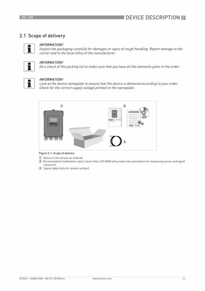
Figure 2-1: Scope of delivery
1 Device in the version as ordered2 Documentation (calibration report, Quick Start, CD-ROM with product documentation for measuring sensor and signal
converter)3 Signal cable (only for remote version)
2 DEVICE DESCRIPTION
12
IFC 100
www.krohne.com 07/2014 - 4000041005 - MA IFC 100 R05 en
2.2 Device description
Electromagnetic flowmeters are designed exclusively to measure the flow and conductivity of electrically conductive, liquid media.
Your measuring device is supplied ready for operation. The factory settings for the operating data have been made in accordance with your order specifications.
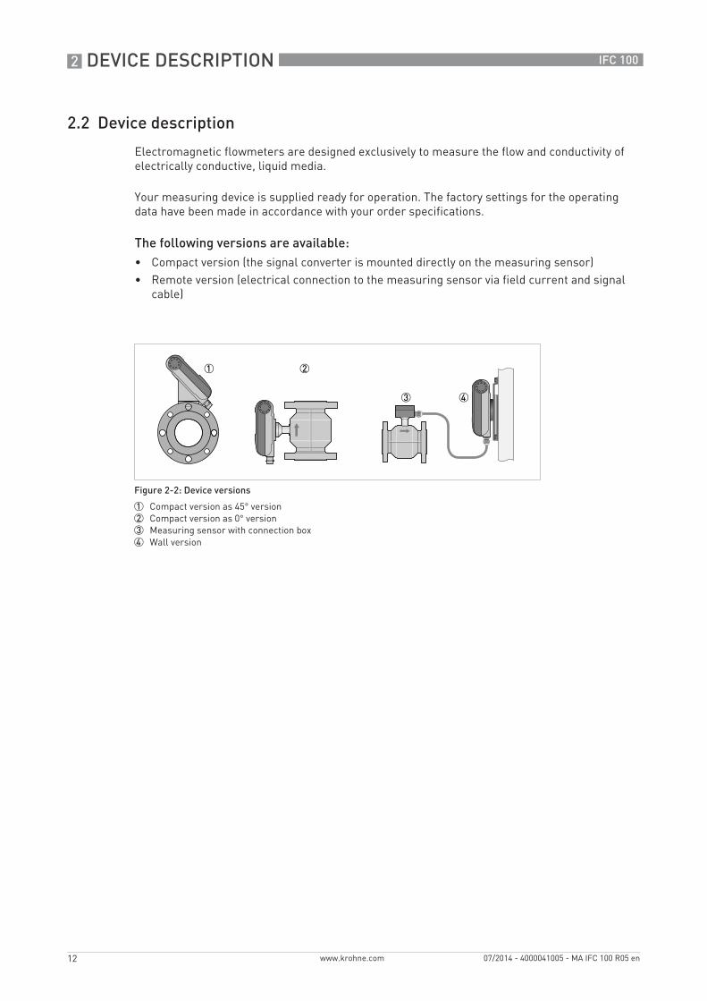
The following versions are available:• Compact version (the signal converter is mounted directly on the measuring sensor)• Remote version (electrical connection to the measuring sensor via field current and signal
cable)
Figure 2-2: Device versions
1 Compact version as 45° version2 Compact version as 0° version3 Measuring sensor with connection box4 Wall version

DEVICE DESCRIPTION 2
13
IFC 100
www.krohne.com07/2014 - 4000041005 - MA IFC 100 R05 en
2.3 Nameplates
2.3.1 Nameplate (example)
INFORMATION!Look at the device nameplate to ensure that the device is delivered according to your order. Check for the correct supply voltage printed on the nameplate.
Figure 2-3: Example of a nameplate
1 Manufacturer2 Power supply data3 Software version4 Tag name5 Approvals-related pressure and temperature thresholds6 GK/GKL values (measuring sensor constants); size (mm /inches); field frequency; protection category; materials of
wetted parts7 Product designation, serial number and manufacturing date
3 INSTALLATION
14
IFC 100
www.krohne.com 07/2014 - 4000041005 - MA IFC 100 R05 en
3.1 General notes on installation
3.2 Storage
• Store the device in a dry, dust-free location.• Avoid continuous direct sunlight.• Store the device in its original packing.• Storage temperature: -40...+70°C / -40...+158°F
3.3 Transport
Signal converter• No special requirements.
Compact version• Do not lift the device by the signal converter housing.• Do not use lifting chains.• To transport flange devices, use lifting straps. Wrap these around both process connections.
3.4 Installation specifications
INFORMATION!Inspect the packaging carefully for damages or signs of rough handling. Report damage to the carrier and to the local office of the manufacturer.
INFORMATION!Do a check of the packing list to make sure that you have all the elements given in the order.
INFORMATION!Look at the device nameplate to ensure that the device is delivered according to your order. Check for the correct supply voltage printed on the nameplate.
INFORMATION!The following precautions must be taken to ensure reliable installation.• Make sure that there is adequate space to the sides.• Protect the signal converter from direct sunlight and install a sun shade if necessary.• Signal converters installed in control cabinets require adequate cooling, e.g. by fan or heat
exchanger.• Do not expose the signal converter to intense vibrations. The measuring devices are tested
for a vibration level in accordance with IEC 68-2-64.
INSTALLATION 3
15
IFC 100
www.krohne.com07/2014 - 4000041005 - MA IFC 100 R05 en
3.5 Mounting of the compact version
3.6 Mounting the wall-mounted housing, remote version
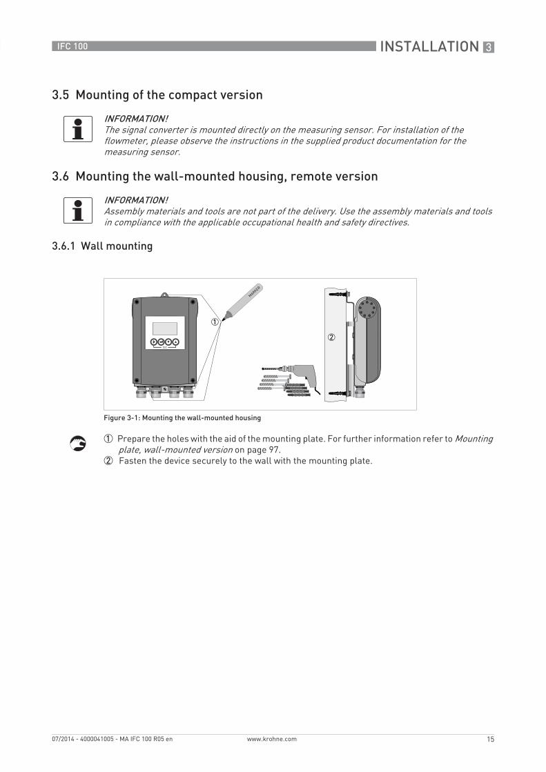
3.6.1 Wall mounting
1 Prepare the holes with the aid of the mounting plate. For further information refer to Mounting plate, wall-mounted version on page 97.
2 Fasten the device securely to the wall with the mounting plate.
INFORMATION!The signal converter is mounted directly on the measuring sensor. For installation of the flowmeter, please observe the instructions in the supplied product documentation for the measuring sensor.
INFORMATION!Assembly materials and tools are not part of the delivery. Use the assembly materials and tools in compliance with the applicable occupational health and safety directives.
Figure 3-1: Mounting the wall-mounted housing
3 INSTALLATION
16
IFC 100
www.krohne.com 07/2014 - 4000041005 - MA IFC 100 R05 en
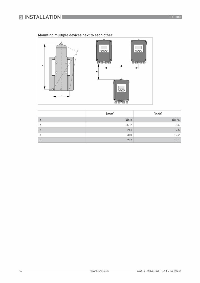
Mounting multiple devices next to each other
[mm] [inch]
a Ø6.5 Ø0.26
b 87.2 3.4
c 241 9.5
d 310 12.2
e 257 10.1
ELECTRICAL CONNECTIONS 4
17
IFC 100
www.krohne.com07/2014 - 4000041005 - MA IFC 100 R05 en
4.1 Safety instructions
4.2 Important notes on electrical connection
DANGER!All work on the electrical connections may only be carried out with the power disconnected. Take note of the voltage data on the nameplate!
DANGER!Observe the national regulations for electrical installations!
DANGER!For devices used in hazardous areas, additional safety notes apply; please refer to the Ex documentation.
WARNING!Observe without fail the local occupational health and safety regulations. Any work done on the electrical components of the measuring device may only be carried out by properly trained specialists.
INFORMATION!Look at the device nameplate to ensure that the device is delivered according to your order. Check for the correct supply voltage printed on the nameplate.
DANGER!Electrical connection is carried out in conformity with the VDE 0100 directive "Regulations for electrical power installations with line voltages up to 1000 V" or equivalent national regulations.
CAUTION!• Use suitable cable entries for the various electrical cables.• The measuring sensor and signal converter have been configured together at the factory. For
this reason, please connect the devices in pairs. Ensure that the measuring sensor constant GK/GKL (see nameplates) are identically set.
• If delivered separately or when installing devices that were not configured together, set the signal converter to the DN size and GK/GKL of the measuring sensor, refer to Function tables on page 56.

4 ELECTRICAL CONNECTIONS
18
IFC 100
www.krohne.com 07/2014 - 4000041005 - MA IFC 100 R05 en
4.3 Electrical cables for remote device versions, notes
4.3.1 Notes on signal cable A
Observe the following notes:• Lay the signal cable with fastening elements.• It is permissible to lay the signal cable in water or in the ground.• The insulating material is flame-retardant to EN 50265-2-1: 1997 and IEC 60322-1-2: 2005.• The signal cable does not contain any halogens and is unplasticized, and remains flexible at
low temperatures.• The connection of the inner shield (10) is carried out via the stranded drain wire (1).• The connection of the outer shield (60) is carried out via the stranded drain wire (6).
4.3.2 Notes on field current cable C
INFORMATION!Signal cable A (type DS 300) with double shield ensures proper transmission of measured values.
DANGER!A shielded 2-wire copper cable is used for the field current cable. The shielding MUSTMUSTMUSTMUST be connected in the housing of the measuring sensor and signal converter.
INFORMATION!The field current cable is not part of the scope of delivery.
ELECTRICAL CONNECTIONS 4
19
IFC 100
www.krohne.com07/2014 - 4000041005 - MA IFC 100 R05 en
4.3.3 Requirements for signal cables provided by the customer
Electrical safety• To EN 60811 (Low Voltage Directive) or equivalent national regulations.
Capacitance of the insulated conductors• Insulated conductor / insulated conductor < 50 pF/m• Insulated conductor / shield < 150 pF/m
Insulation resistance• Riso > 100 GΩ x km
• Umax < 24 V
• Imax < 100 mA
Test voltages• Insulated conductor / inner shield 500 V• Insulated conductor / insulated conductor 1000 V• Insulated conductor / outer shield 1000 V
Twisting of the insulated conductors• At least 10 twists per meter, important for screening magnetic fields.
INFORMATION!If the signal cable was not ordered, it is to be provided by the customer. The following requirements regarding the electrical values of the signal cable must be observed:
4 ELECTRICAL CONNECTIONS
20
IFC 100
www.krohne.com 07/2014 - 4000041005 - MA IFC 100 R05 en
4.4 Preparing the signal and field current cables
4.4.1 Signal cable A (type DS 300), construction
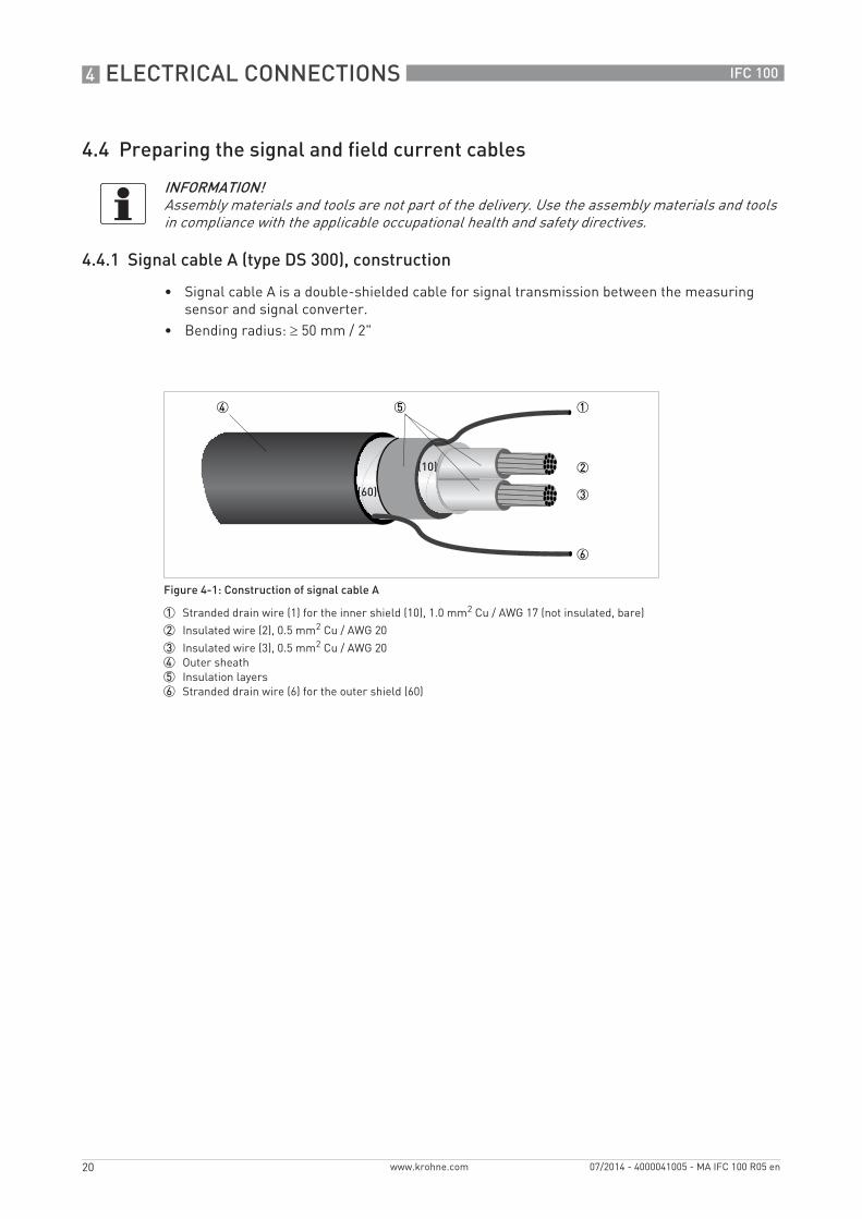
• Signal cable A is a double-shielded cable for signal transmission between the measuring sensor and signal converter.
• Bending radius: ≥ 50 mm / 2"
INFORMATION!Assembly materials and tools are not part of the delivery. Use the assembly materials and tools in compliance with the applicable occupational health and safety directives.
Figure 4-1: Construction of signal cable A
1 Stranded drain wire (1) for the inner shield (10), 1.0 mm2 Cu / AWG 17 (not insulated, bare)
2 Insulated wire (2), 0.5 mm2 Cu / AWG 20
3 Insulated wire (3), 0.5 mm2 Cu / AWG 204 Outer sheath5 Insulation layers6 Stranded drain wire (6) for the outer shield (60)
ELECTRICAL CONNECTIONS 4
21
IFC 100
www.krohne.com07/2014 - 4000041005 - MA IFC 100 R05 en
4.4.2 Preparing signal cable A, connection to signal converter
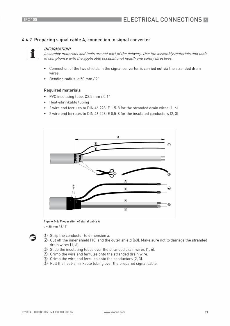
• Connection of the two shields in the signal converter is carried out via the stranded drain wires.
• Bending radius: ≥ 50 mm / 2"
Required materials• PVC insulating tube, Ø2.5 mm / 0.1"• Heat-shrinkable tubing• 2 wire end ferrules to DIN 46 228: E 1.5-8 for the stranded drain wires (1, 6)• 2 wire end ferrules to DIN 46 228: E 0.5-8 for the insulated conductors (2, 3)
1 Strip the conductor to dimension a.2 Cut off the inner shield (10) and the outer shield (60). Make sure not to damage the stranded
drain wires (1, 6).3 Slide the insulating tubes over the stranded drain wires (1, 6).4 Crimp the wire end ferrules onto the stranded drain wire.5 Crimp the wire end ferrules onto the conductors (2, 3).6 Pull the heat-shrinkable tubing over the prepared signal cable.
INFORMATION!Assembly materials and tools are not part of the delivery. Use the assembly materials and tools in compliance with the applicable occupational health and safety directives.
Figure 4-2: Preparation of signal cable A
a = 80 mm / 3.15"
4 ELECTRICAL CONNECTIONS
22
IFC 100
www.krohne.com 07/2014 - 4000041005 - MA IFC 100 R05 en
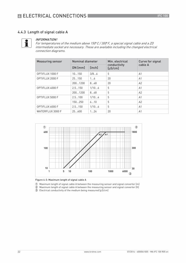
4.4.3 Length of signal cable A
INFORMATION!For temperatures of the medium above 150°C / 300°F, a special signal cable and a ZD intermediate socket are necessary. These are available including the changed electrical connection diagrams.
Measuring sensor Nominal diameter Min. electrical conductivity[µS/cm]
Curve for signal cable A
DN [mm] [inch]
OPTIFLUX 1000 F 10...150 3/8...6 5 A1
OPTIFLUX 2000 F 25...150 1...6 20 A1
200...1200 8...48 20 A2
OPTIFLUX 4000 F 2.5...150 1/10...6 5 A1
200...1200 8...48 5 A2
OPTIFLUX 5000 F 2.5...100 1/10...4 5 A1
150...250 6...10 5 A2
OPTIFLUX 6000 F 2.5...150 1/10...6 5 A1
WATERFLUX 3000 F 25...600 1...24 20 A1
Figure 4-3: Maximum length of signal cable A
1 Maximum length of signal cable A between the measuring sensor and signal converter [m]2 Maximum length of signal cable A between the measuring sensor and signal converter [ft]3 Electrical conductivity of the medium being measured [μS/cm]
ELECTRICAL CONNECTIONS 4
23
IFC 100
www.krohne.com07/2014 - 4000041005 - MA IFC 100 R05 en
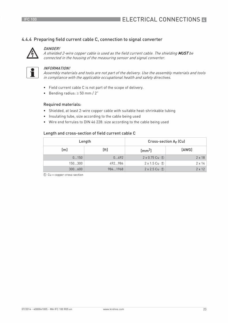
4.4.4 Preparing field current cable C, connection to signal converter
• Field current cable C is not part of the scope of delivery.• Bending radius: ≥ 50 mm / 2"
Required materials:• Shielded, at least 2-wire copper cable with suitable heat-shrinkable tubing• Insulating tube, size according to the cable being used• Wire end ferrules to DIN 46 228: size according to the cable being used
Length and cross-section of field current cable C
DANGER!A shielded 2-wire copper cable is used as the field current cable. The shielding MUSTMUSTMUSTMUST be connected in the housing of the measuring sensor and signal converter.
INFORMATION!Assembly materials and tools are not part of the delivery. Use the assembly materials and tools in compliance with the applicable occupational health and safety directives.
Length Cross-section AF (Cu)
[m] [ft] [mm2] [AWG]
0...150 0...492 2 x 0.75 Cu 1 2 x 18
150...300 492...984 2 x 1.5 Cu 1 2 x 14
300...600 984...1968 2 x 2.5 Cu 1 2 x 12
1 Cu = copper cross-section
4 ELECTRICAL CONNECTIONS
24
IFC 100
www.krohne.com 07/2014 - 4000041005 - MA IFC 100 R05 en
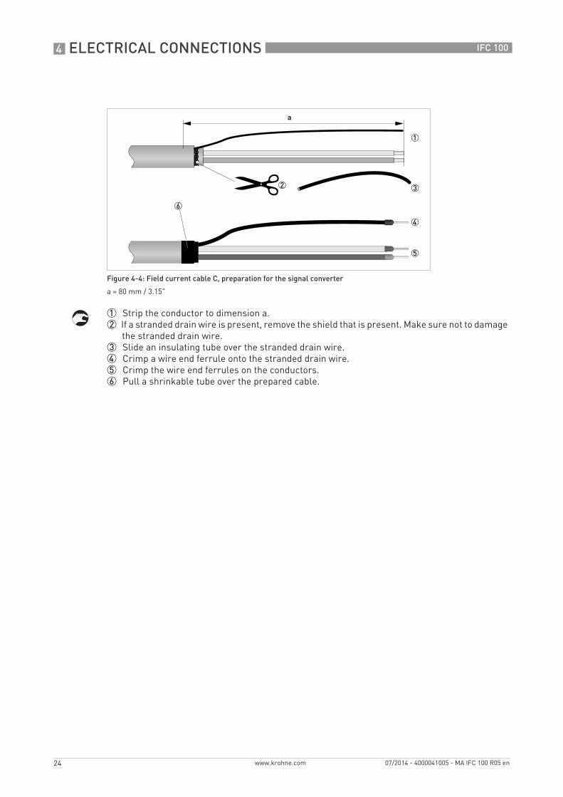
1 Strip the conductor to dimension a.2 If a stranded drain wire is present, remove the shield that is present. Make sure not to damage
the stranded drain wire.3 Slide an insulating tube over the stranded drain wire.4 Crimp a wire end ferrule onto the stranded drain wire.5 Crimp the wire end ferrules on the conductors.6 Pull a shrinkable tube over the prepared cable.
Figure 4-4: Field current cable C, preparation for the signal converter
a = 80 mm / 3.15"
ELECTRICAL CONNECTIONS 4
25
IFC 100
www.krohne.com07/2014 - 4000041005 - MA IFC 100 R05 en
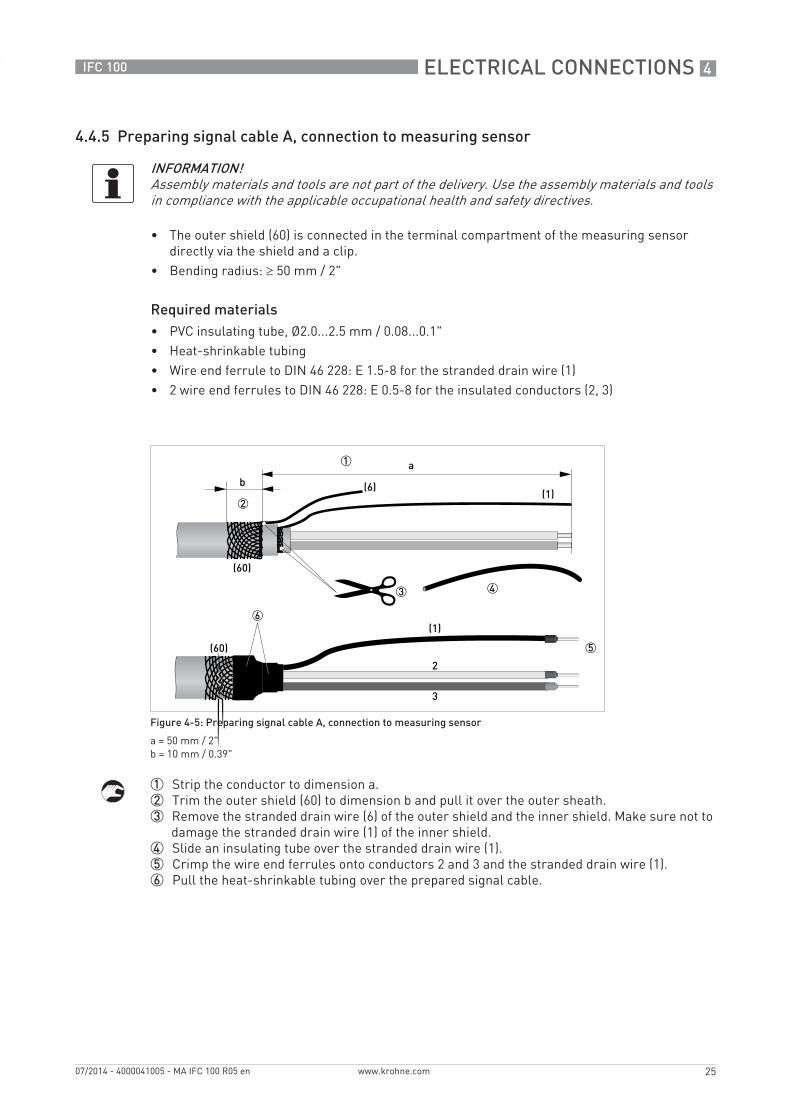
4.4.5 Preparing signal cable A, connection to measuring sensor
• The outer shield (60) is connected in the terminal compartment of the measuring sensor directly via the shield and a clip.
• Bending radius: ≥ 50 mm / 2"
Required materials• PVC insulating tube, Ø2.0...2.5 mm / 0.08...0.1"• Heat-shrinkable tubing• Wire end ferrule to DIN 46 228: E 1.5-8 for the stranded drain wire (1)• 2 wire end ferrules to DIN 46 228: E 0.5-8 for the insulated conductors (2, 3)
1 Strip the conductor to dimension a.2 Trim the outer shield (60) to dimension b and pull it over the outer sheath.3 Remove the stranded drain wire (6) of the outer shield and the inner shield. Make sure not to
damage the stranded drain wire (1) of the inner shield.4 Slide an insulating tube over the stranded drain wire (1).5 Crimp the wire end ferrules onto conductors 2 and 3 and the stranded drain wire (1).6 Pull the heat-shrinkable tubing over the prepared signal cable.
INFORMATION!Assembly materials and tools are not part of the delivery. Use the assembly materials and tools in compliance with the applicable occupational health and safety directives.
Figure 4-5: Preparing signal cable A, connection to measuring sensor
a = 50 mm / 2"b = 10 mm / 0.39"
4 ELECTRICAL CONNECTIONS
26
IFC 100
www.krohne.com 07/2014 - 4000041005 - MA IFC 100 R05 en
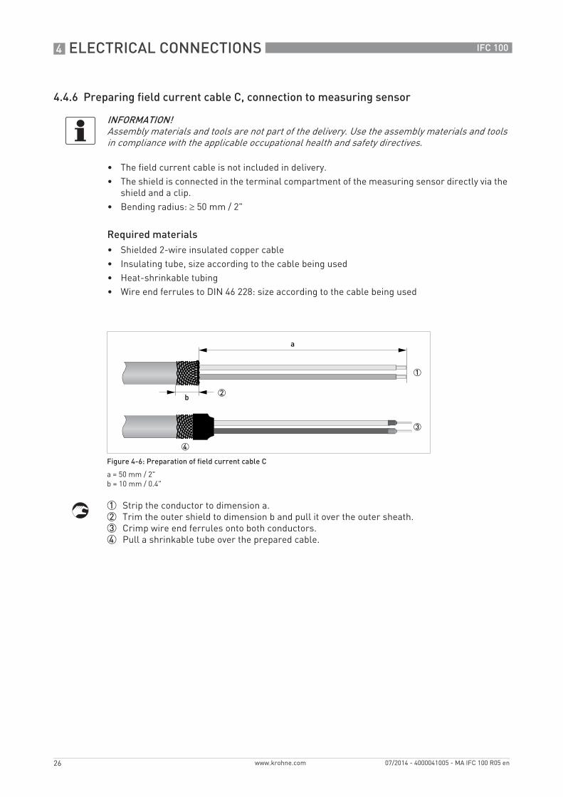
4.4.6 Preparing field current cable C, connection to measuring sensor
• The field current cable is not included in delivery.• The shield is connected in the terminal compartment of the measuring sensor directly via the
shield and a clip.• Bending radius: ≥ 50 mm / 2"
Required materials• Shielded 2-wire insulated copper cable• Insulating tube, size according to the cable being used• Heat-shrinkable tubing• Wire end ferrules to DIN 46 228: size according to the cable being used
1 Strip the conductor to dimension a.2 Trim the outer shield to dimension b and pull it over the outer sheath.3 Crimp wire end ferrules onto both conductors.4 Pull a shrinkable tube over the prepared cable.
INFORMATION!Assembly materials and tools are not part of the delivery. Use the assembly materials and tools in compliance with the applicable occupational health and safety directives.
Figure 4-6: Preparation of field current cable C
a = 50 mm / 2"b = 10 mm / 0.4"
ELECTRICAL CONNECTIONS 4
27
IFC 100
www.krohne.com07/2014 - 4000041005 - MA IFC 100 R05 en
4.5 Connecting the signal and field current cables
DANGER!Cables may only be connected when the power is switched off.
DANGER!The device must be grounded in accordance with regulations in order to protect personnel against electric shocks.
DANGER!For devices used in hazardous areas, additional safety notes apply; please refer to the Ex documentation.
WARNING!Observe without fail the local occupational health and safety regulations. Any work done on the electrical components of the measuring device may only be carried out by properly trained specialists.

4 ELECTRICAL CONNECTIONS
28
IFC 100
www.krohne.com 07/2014 - 4000041005 - MA IFC 100 R05 en
4.5.1 Connecting the signal and field current cables to the signal converter, remote version
Open housing
1 Loosen the 4 screws with a suitable tool.2 Lift the housing at the top and bottom at the same time.3 Slide the housing cover upward.4 The housing cover is guided and held by the inside hinge.
INFORMATION!The compact version is supplied preassembled from the factory.
Figure 4-7: Open housing

ELECTRICAL CONNECTIONS 4
29
IFC 100
www.krohne.com07/2014 - 4000041005 - MA IFC 100 R05 en
Connecting the signal and field current cables
Connect the electrical conductors as follows:1 Push the lever downwards with a screwdriver in good condition (blade: 3.5 mm wide and
0.5 mm thick).2 Insert the electrical conductor into the plug.3 The conductor will be clamped as soon as the lever is released.
Figure 4-8: Function of the electrical connection terminal
Figure 4-9: Connecting the signal and field current cables
1 Cable entry for field current cable2 Cable entry for signal cable3 Connecting the field current cable shield4 Electrical conductor (7)5 Electrical conductor (8)6 Stranded drain wire (1) of the inner shield (10) of the signal cable7 Electrical conductor (2)8 Electrical conductor (3)9 Stranded drain wire (S) of the outer shield (60)
4 ELECTRICAL CONNECTIONS
30
IFC 100
www.krohne.com 07/2014 - 4000041005 - MA IFC 100 R05 en
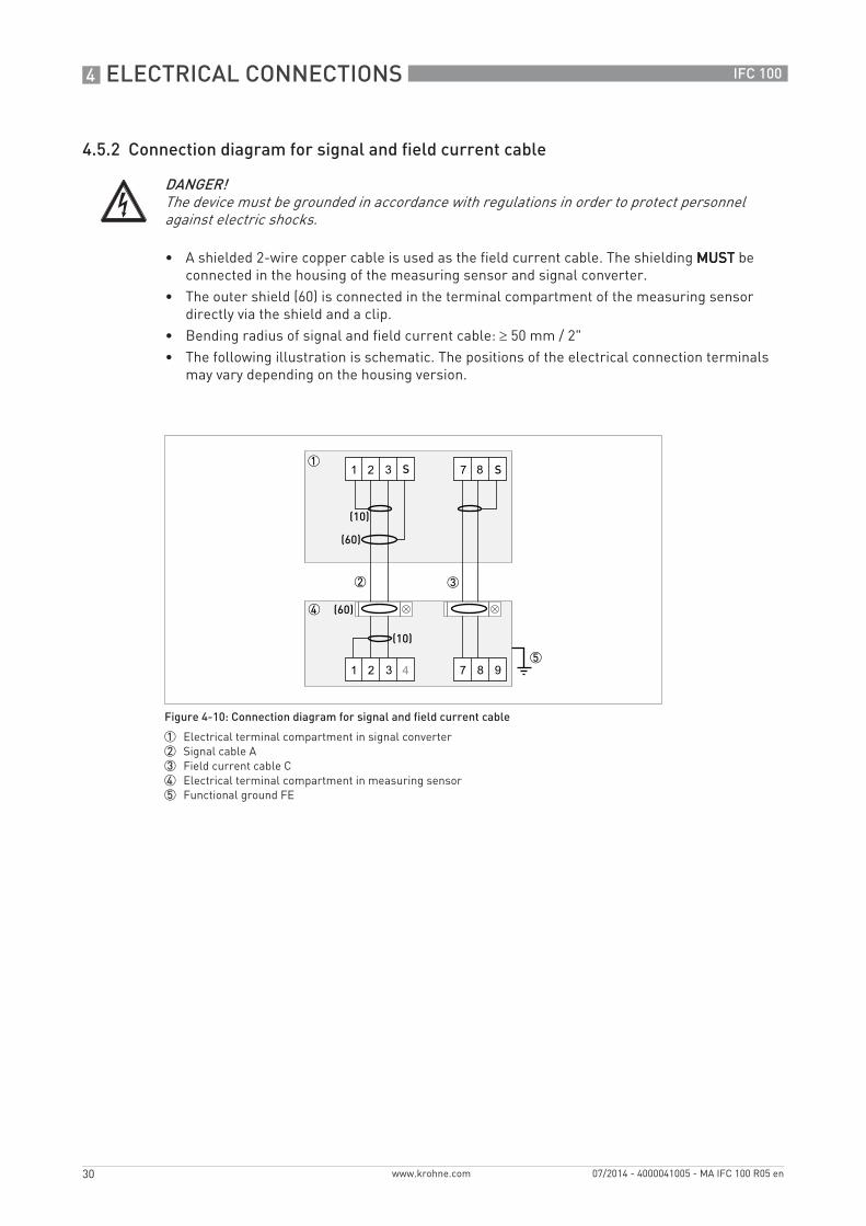
4.5.2 Connection diagram for signal and field current cable
• A shielded 2-wire copper cable is used as the field current cable. The shielding MUSTMUSTMUSTMUST be connected in the housing of the measuring sensor and signal converter.
• The outer shield (60) is connected in the terminal compartment of the measuring sensor directly via the shield and a clip.
• Bending radius of signal and field current cable: ≥ 50 mm / 2"• The following illustration is schematic. The positions of the electrical connection terminals
may vary depending on the housing version.
DANGER!The device must be grounded in accordance with regulations in order to protect personnel against electric shocks.
Figure 4-10: Connection diagram for signal and field current cable
1 Electrical terminal compartment in signal converter2 Signal cable A3 Field current cable C4 Electrical terminal compartment in measuring sensor5 Functional ground FE
ELECTRICAL CONNECTIONS 4
31
IFC 100
www.krohne.com07/2014 - 4000041005 - MA IFC 100 R05 en
4.6 Grounding the measuring sensor
4.6.1 Classical method
• The measuring sensor must be properly grounded.• The grounding cable should not transmit any interference voltages.• Do not use the grounding cable to connect any other electrical devices to ground at the same
time.• The measuring sensors are connected to ground by means of a functional grounding
conductor FE.• Special grounding instructions for the various measuring sensors are provided in the
separate documentation for the measuring sensor.• The documentation for the measuring sensor also contain descriptions on how to use
grounding rings and how to install the measuring sensor in metal or plastic pipes or in pipes which are coated on the inside.
CAUTION!There should be no difference in potential between the measuring sensor and the housing or protective earth of the signal converter!
4 ELECTRICAL CONNECTIONS
32
IFC 100
www.krohne.com 07/2014 - 4000041005 - MA IFC 100 R05 en
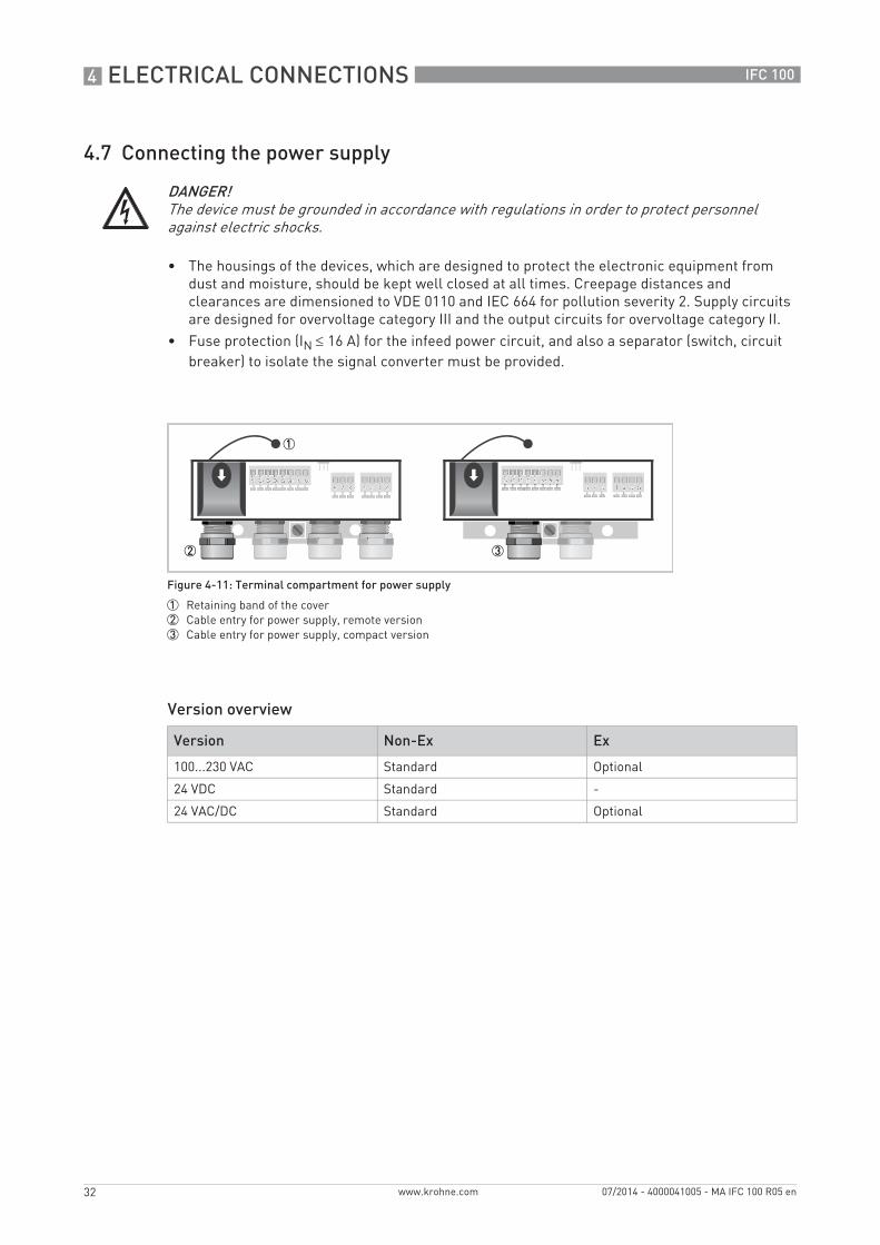
4.7 Connecting the power supply
• The housings of the devices, which are designed to protect the electronic equipment from dust and moisture, should be kept well closed at all times. Creepage distances and clearances are dimensioned to VDE 0110 and IEC 664 for pollution severity 2. Supply circuits are designed for overvoltage category III and the output circuits for overvoltage category II.
• Fuse protection (IN ≤ 16 A) for the infeed power circuit, and also a separator (switch, circuit breaker) to isolate the signal converter must be provided.
Version overview
DANGER!The device must be grounded in accordance with regulations in order to protect personnel against electric shocks.
Figure 4-11: Terminal compartment for power supply
1 Retaining band of the cover2 Cable entry for power supply, remote version3 Cable entry for power supply, compact version
Version Non-Ex Ex
100...230 VAC Standard Optional
24 VDC Standard -
24 VAC/DC Standard Optional
ELECTRICAL CONNECTIONS 4
33
IFC 100
www.krohne.com07/2014 - 4000041005 - MA IFC 100 R05 en
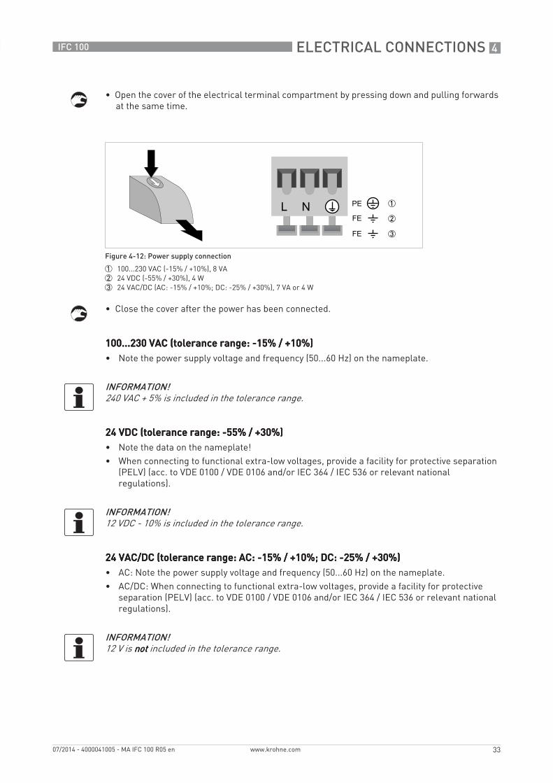
• Open the cover of the electrical terminal compartment by pressing down and pulling forwards at the same time.
• Close the cover after the power has been connected.
100...230 VAC (tolerance range: -15% / +10%)100...230 VAC (tolerance range: -15% / +10%)100...230 VAC (tolerance range: -15% / +10%)100...230 VAC (tolerance range: -15% / +10%)• Note the power supply voltage and frequency (50...60 Hz) on the nameplate.
24 VDC (tolerance range: -55% / +30%)24 VDC (tolerance range: -55% / +30%)24 VDC (tolerance range: -55% / +30%)24 VDC (tolerance range: -55% / +30%)• Note the data on the nameplate!• When connecting to functional extra-low voltages, provide a facility for protective separation
(PELV) (acc. to VDE 0100 / VDE 0106 and/or IEC 364 / IEC 536 or relevant national regulations).
24 VAC/DC (tolerance range: AC: -15% / +10%; DC: -25% / +30%)24 VAC/DC (tolerance range: AC: -15% / +10%; DC: -25% / +30%)24 VAC/DC (tolerance range: AC: -15% / +10%; DC: -25% / +30%)24 VAC/DC (tolerance range: AC: -15% / +10%; DC: -25% / +30%)• AC: Note the power supply voltage and frequency (50...60 Hz) on the nameplate.• AC/DC: When connecting to functional extra-low voltages, provide a facility for protective
separation (PELV) (acc. to VDE 0100 / VDE 0106 and/or IEC 364 / IEC 536 or relevant national regulations).
Figure 4-12: Power supply connection
1 100...230 VAC (-15% / +10%), 8 VA2 24 VDC (-55% / +30%), 4 W3 24 VAC/DC (AC: -15% / +10%; DC: -25% / +30%), 7 VA or 4 W
INFORMATION!240 VAC + 5% is included in the tolerance range.
INFORMATION!12 VDC - 10% is included in the tolerance range.
INFORMATION!12 V is notnotnotnot included in the tolerance range.
4 ELECTRICAL CONNECTIONS
34
IFC 100
www.krohne.com 07/2014 - 4000041005 - MA IFC 100 R05 en
4.8 Inputs and outputs, overview
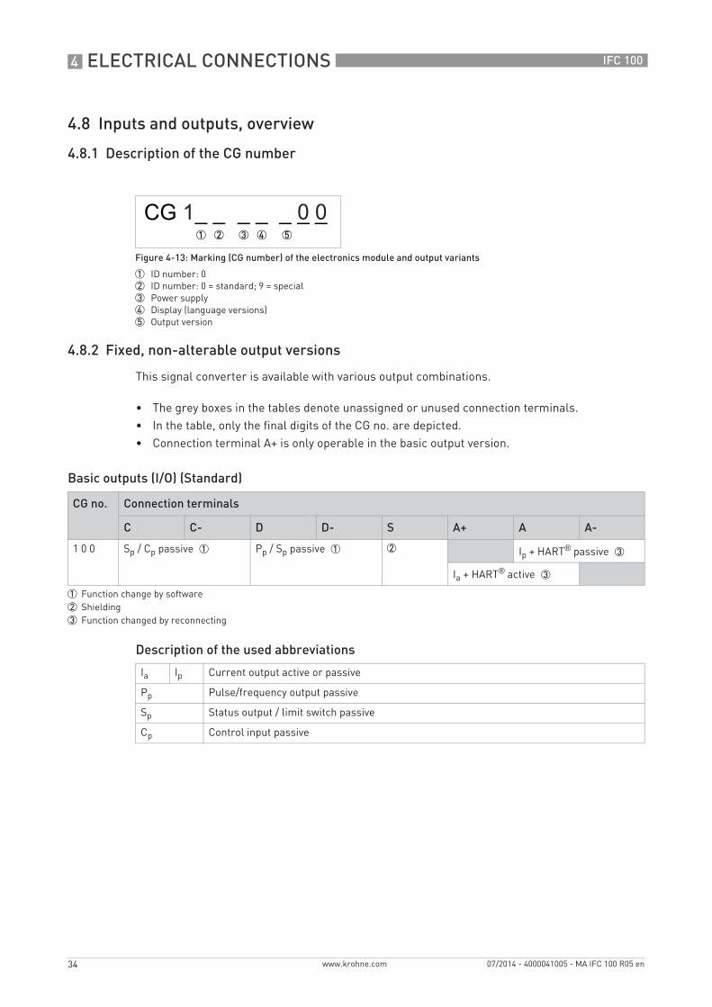
4.8.1 Description of the CG number
4.8.2 Fixed, non-alterable output versions
This signal converter is available with various output combinations.
• The grey boxes in the tables denote unassigned or unused connection terminals.• In the table, only the final digits of the CG no. are depicted.• Connection terminal A+ is only operable in the basic output version.
Basic outputs (I/O) (Standard)
Description of the used abbreviations
Figure 4-13: Marking (CG number) of the electronics module and output variants
1 ID number: 02 ID number: 0 = standard; 9 = special3 Power supply4 Display (language versions)5 Output version
CG no. Connection terminals
C C- D D- S A+ A A-
1 0 0 Sp / Cp passive 1 Pp / Sp passive 1 2 Ip + HART® passive 3
Ia + HART® active 3
1 Function change by software2 Shielding3 Function changed by reconnecting
Ia Ip Current output active or passive
Pp Pulse/frequency output passive
Sp Status output / limit switch passive
Cp Control input passive
ELECTRICAL CONNECTIONS 4
35
IFC 100
www.krohne.com07/2014 - 4000041005 - MA IFC 100 R05 en
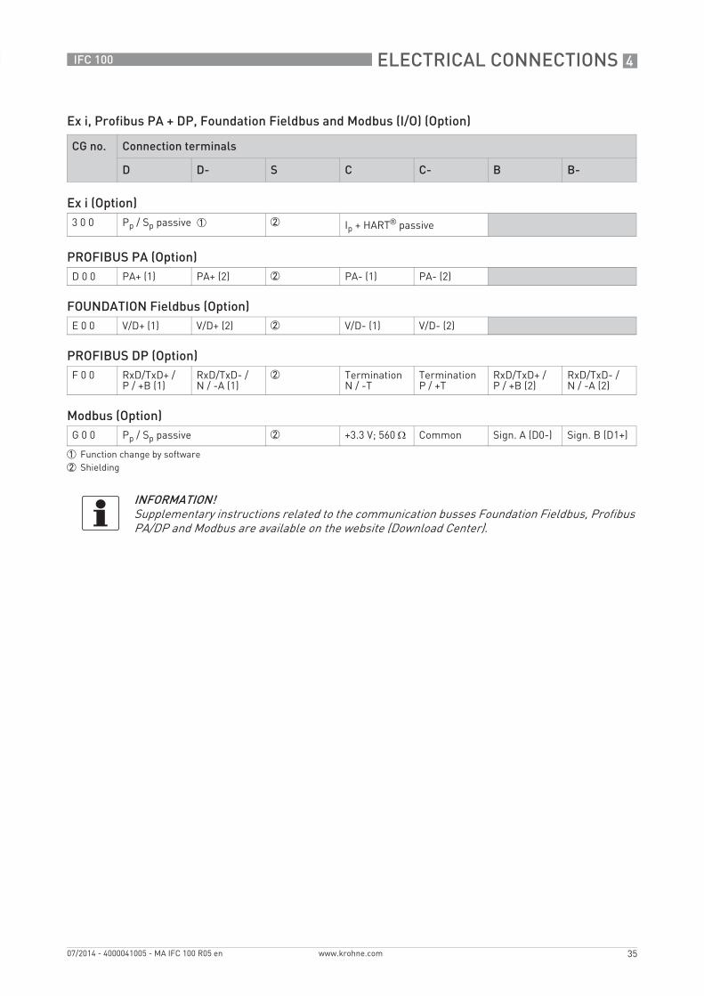
Ex i, Profibus PA + DP, Foundation Fieldbus and Modbus (I/O) (Option)
CG no. Connection terminals
D D- S C C- B B-
Ex i (Option)3 0 0 Pp / Sp passive 1 2 Ip + HART® passive
PROFIBUS PA (Option)D 0 0 PA+ (1) PA+ (2) 2 PA- (1) PA- (2)
FOUNDATION Fieldbus (Option)E 0 0 V/D+ (1) V/D+ (2) 2 V/D- (1) V/D- (2)
PROFIBUS DP (Option)F 0 0 RxD/TxD+ /
P / +B (1)RxD/TxD- / N / -A (1)
2 Termination N / -T
Termination P / +T
RxD/TxD+ / P / +B (2)
RxD/TxD- / N / -A (2)
Modbus (Option)G 0 0 Pp / Sp passive 2 +3.3 V; 560 Ω Common Sign. A (D0-) Sign. B (D1+)
1 Function change by software2 Shielding
INFORMATION!Supplementary instructions related to the communication busses Foundation Fieldbus, Profibus PA/DP and Modbus are available on the website (Download Center).

4 ELECTRICAL CONNECTIONS
36
IFC 100
www.krohne.com 07/2014 - 4000041005 - MA IFC 100 R05 en
4.9 Description of the inputs and outputs
4.9.1 Current output
• All outputs are electrically isolated from each other and from all other circuits.• All operating data and functions can be adjusted.• Passive mode:
External power Uext ≤ 32 VDC at I ≤ 22 mA
• Active mode:Load impedance RL ≤ 750 Ω at I ≤ 22 mA
• Self-monitoring: interruption or load impedance too high in the current output loop• Error message possible via status output, error indication on LC display.• Current value error detection can be adjusted.• Automatic range conversion via threshold. The setting range for the threshold is between 5
and 80% of Q100%, ± 0...5% hysteresis (corresponding ratio from smaller to larger range of 1:20 to 1:1.25).Signaling of the active range possible via a status output (adjustable).
• Forward/reverse flow measurement (F/R mode) is possible.
INFORMATION!For further information refer to Connection diagrams of outputs on page 41 and refer to Technical data on page 85.
DANGER!For devices used in hazardous areas, additional safety notes apply; please refer to the Ex documentation.
ELECTRICAL CONNECTIONS 4
37
IFC 100
www.krohne.com07/2014 - 4000041005 - MA IFC 100 R05 en
4.9.2 Pulse output and frequency output
• All outputs are electrically isolated from each other and from all other circuits.• All operating data and functions can be adjusted.• Passive mode:
External power supply required: Uext ≤ 32 VDC
For the basic I/O signal converter:For the basic I/O signal converter:For the basic I/O signal converter:For the basic I/O signal converter:I ≤ 20 mA at f ≤ 10 kHz (over range up to fmax ≤ 12 kHz)I ≤ 100 mA at f ≤ 100 Hz
For the Ex i I/O signal converter:For the Ex i I/O signal converter:For the Ex i I/O signal converter:For the Ex i I/O signal converter:NAMUR characterictic 4.7 mA / 0.77 mA at f ≤ 10 kHz (over range up to fmax ≤ 12 kHz)
For the Modbus I/O signal converter:For the Modbus I/O signal converter:For the Modbus I/O signal converter:For the Modbus I/O signal converter:I ≤ 100 mA at f ≤ 1 kHz (over range up to fmax ≤ 1.2 kHz)
• Scaling:Frequency output: in pulses per time unit (e.g. 1000 pulses/s at Q100%);Pulse output: quantity per pulse.
• Pulse width:symmetric (pulse duty factor 1:1, independent of output frequency)automatic (with fixed pulse width, duty factor approx. 1:1 at Q100%)fixed (pulse width adjustable as required from 0.05 ms...2 s)
• Forward/reverse flow measurement (F/R mode) is possible.• The pulse output and frequency output can also be used as a status output / limit switch.
INFORMATION!For further information refer to Connection diagrams of outputs on page 41 and refer to Technical data on page 85.
DANGER!For devices used in hazardous areas, additional safety notes apply; please refer to the Ex documentation.

4 ELECTRICAL CONNECTIONS
38
IFC 100
www.krohne.com 07/2014 - 4000041005 - MA IFC 100 R05 en
4.9.3 Status output and limit switch
• The status outputs / limit switches are electrically isolated from each other and from all other circuits.
• The output stages of the status outputs / limit switches behave like relay contacts.• All operating data and functions can be adjusted.• Passive mode:
External power supply required: Uext ≤ 32 VDC; I ≤ 100 mA
For the Ex i I/O signal converter:For the Ex i I/O signal converter:For the Ex i I/O signal converter:For the Ex i I/O signal converter:NAMUR characterictic 4.7 mA / 0.77 mA
• For information on the adjustable operating states refer to Function tables on page 56.
INFORMATION!For further information refer to Connection diagrams of outputs on page 41 and refer to Technical data on page 85.
DANGER!For devices used in hazardous areas, additional safety notes apply; please refer to the Ex documentation.
ELECTRICAL CONNECTIONS 4
39
IFC 100
www.krohne.com07/2014 - 4000041005 - MA IFC 100 R05 en
4.9.4 Control input
• All control inputs are electrically isolated from each other and from all other circuits.• All operating data and functions can be adjusted.• Passive mode:
External power supply required: Uext ≤ 32 VDC
• For information on the adjustable operating states refer to Function tables on page 56.
INFORMATION!Which I/O version and inputs/outputs are installed in your signal converter are indicated on the sticker in the cover of the terminal compartment.
INFORMATION!For further information refer to Connection diagrams of outputs on page 41 and refer to Technical data on page 85.
4 ELECTRICAL CONNECTIONS
40
IFC 100
www.krohne.com 07/2014 - 4000041005 - MA IFC 100 R05 en
4.10 Electrical connection of the outputs
4.10.1 Electrical connection of the outputs
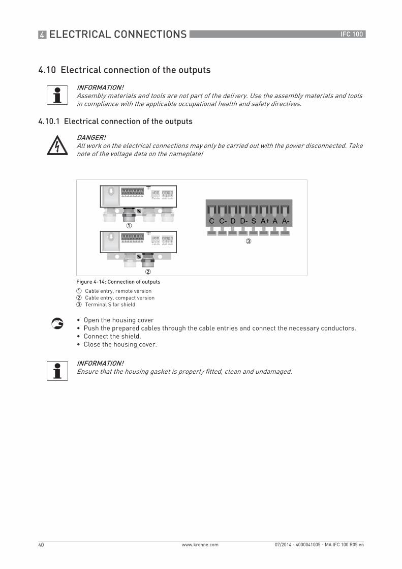
• Open the housing cover• Push the prepared cables through the cable entries and connect the necessary conductors.• Connect the shield.• Close the housing cover.
INFORMATION!Assembly materials and tools are not part of the delivery. Use the assembly materials and tools in compliance with the applicable occupational health and safety directives.
DANGER!All work on the electrical connections may only be carried out with the power disconnected. Take note of the voltage data on the nameplate!
Figure 4-14: Connection of outputs
1 Cable entry, remote version2 Cable entry, compact version3 Terminal S for shield
INFORMATION!Ensure that the housing gasket is properly fitted, clean and undamaged.
ELECTRICAL CONNECTIONS 4
41
IFC 100
www.krohne.com07/2014 - 4000041005 - MA IFC 100 R05 en
4.10.2 Laying electrical cables correctly
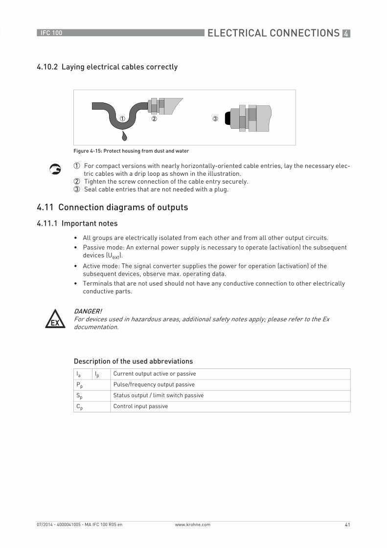
1 For compact versions with nearly horizontally-oriented cable entries, lay the necessary elec-tric cables with a drip loop as shown in the illustration.
2 Tighten the screw connection of the cable entry securely.3 Seal cable entries that are not needed with a plug.
4.11 Connection diagrams of outputs
4.11.1 Important notes
• All groups are electrically isolated from each other and from all other output circuits.• Passive mode: An external power supply is necessary to operate (activation) the subsequent
devices (Uext).
• Active mode: The signal converter supplies the power for operation (activation) of the subsequent devices, observe max. operating data.
• Terminals that are not used should not have any conductive connection to other electrically conductive parts.
Description of the used abbreviations
Figure 4-15: Protect housing from dust and water
DANGER!For devices used in hazardous areas, additional safety notes apply; please refer to the Ex documentation.
Ia Ip Current output active or passive
Pp Pulse/frequency output passive
Sp Status output / limit switch passive
Cp Control input passive
4 ELECTRICAL CONNECTIONS
42
IFC 100
www.krohne.com 07/2014 - 4000041005 - MA IFC 100 R05 en
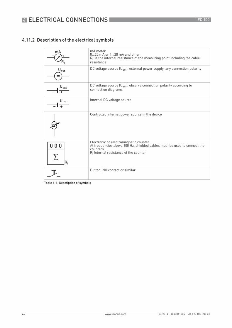
4.11.2 Description of the electrical symbols
mA meter0...20 mA or 4...20 mA and otherRL is the internal resistance of the measuring point including the cable resistance
DC voltage source (Uext), external power supply, any connection polarity
DC voltage source (Uext), observe connection polarity according to connection diagrams
Internal DC voltage source
Controlled internal power source in the device
Electronic or electromagnetic counterAt frequencies above 100 Hz, shielded cables must be used to connect the counters.Ri Internal resistance of the counter
Button, NO contact or similar
Table 4-1: Description of symbols
ELECTRICAL CONNECTIONS 4
43
IFC 100
www.krohne.com07/2014 - 4000041005 - MA IFC 100 R05 en
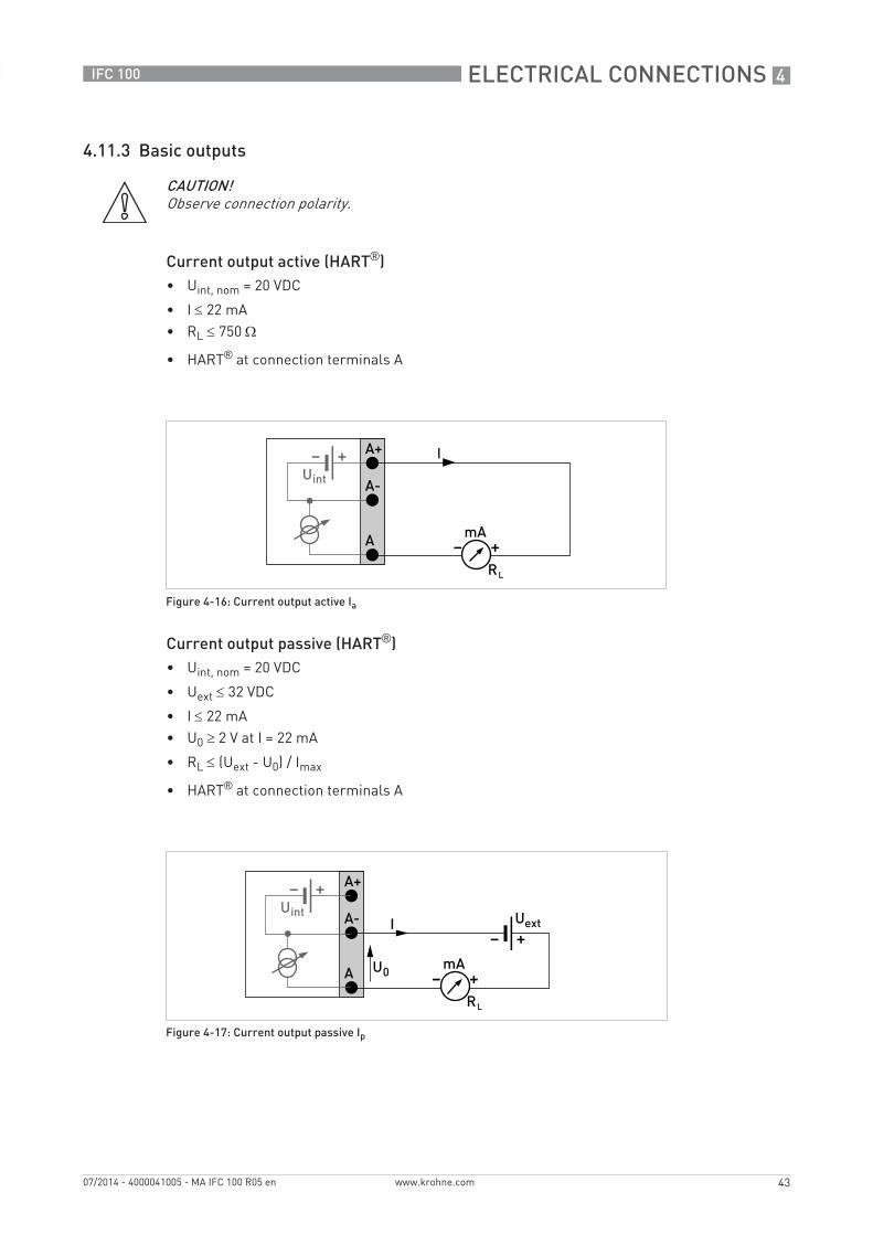
4.11.3 Basic outputs
Current output active (HART®)• Uint, nom = 20 VDC
• I ≤ 22 mA• RL ≤ 750 Ω
• HART® at connection terminals A
Current output passive (HART®)• Uint, nom = 20 VDC
• Uext ≤ 32 VDC
• I ≤ 22 mA• U0 ≥ 2 V at I = 22 mA
• RL ≤ (Uext - U0) / Imax
• HART® at connection terminals A
CAUTION!Observe connection polarity.
Figure 4-16: Current output active Ia
Figure 4-17: Current output passive Ip
4 ELECTRICAL CONNECTIONS
44
IFC 100
www.krohne.com 07/2014 - 4000041005 - MA IFC 100 R05 en
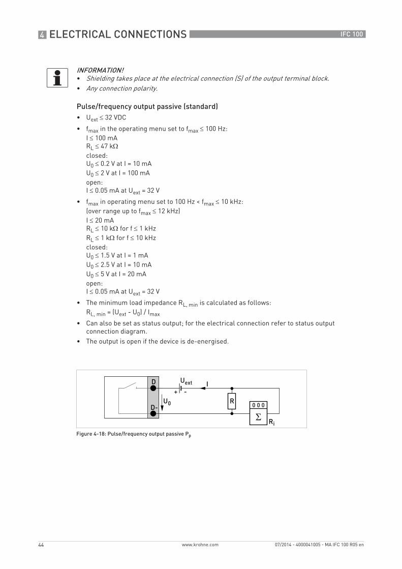
Pulse/frequency output passive (standard)• Uext ≤ 32 VDC
• fmax in the operating menu set to fmax ≤ 100 Hz: I ≤ 100 mARL ≤ 47 kΩclosed:U0 ≤ 0.2 V at I = 10 mAU0 ≤ 2 V at I = 100 mAopen:I ≤ 0.05 mA at Uext = 32 V
• fmax in operating menu set to 100 Hz < fmax ≤ 10 kHz:(over range up to fmax ≤ 12 kHz)I ≤ 20 mARL ≤ 10 kΩ for f ≤ 1 kHzRL ≤ 1 kΩ for f ≤ 10 kHzclosed:U0 ≤ 1.5 V at I = 1 mAU0 ≤ 2.5 V at I = 10 mAU0 ≤ 5 V at I = 20 mAopen:I ≤ 0.05 mA at Uext = 32 V
• The minimum load impedance RL, min is calculated as follows:RL, min = (Uext - U0) / Imax
• Can also be set as status output; for the electrical connection refer to status output connection diagram.
• The output is open if the device is de-energised.
INFORMATION!• Shielding takes place at the electrical connection (S) of the output terminal block.• Any connection polarity.
Figure 4-18: Pulse/frequency output passive Pp
ELECTRICAL CONNECTIONS 4
45
IFC 100
www.krohne.com07/2014 - 4000041005 - MA IFC 100 R05 en
Pulse/frequency output passive (Modbus)• Uext ≤ 32 VDC
• fmax in the operating menu set to fmax ≤ 1 kHz:I ≤ 100 mARL ≤ 47 kΩclosed:U0, max = 0.2 V at I ≤ 10 mAU0, max = 2 V at I ≤ 100 mAopen:I ≤ 0.05 mA at Uext = 32 VDC
• The minimum load impedance RL, min is calculated as follows:RL, min = (Uext - U0) / Imax
• Can also be set as status output; for the electrical connection refer to status output connection diagram.
• The output is open if the device is de-energised.
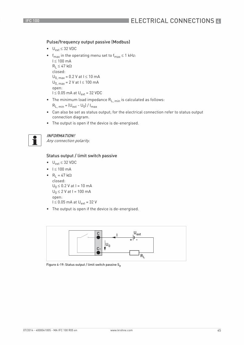
Status output / limit switch passive• Uext ≤ 32 VDC
• I ≤ 100 mA• RL = 47 kΩ
closed:U0 ≤ 0.2 V at I = 10 mAU0 ≤ 2 V at I = 100 mAopen:I ≤ 0.05 mA at Uext = 32 V
• The output is open if the device is de-energised.
INFORMATION!Any connection polarity.
Figure 4-19: Status output / limit switch passive Sp
4 ELECTRICAL CONNECTIONS
46
IFC 100
www.krohne.com 07/2014 - 4000041005 - MA IFC 100 R05 en
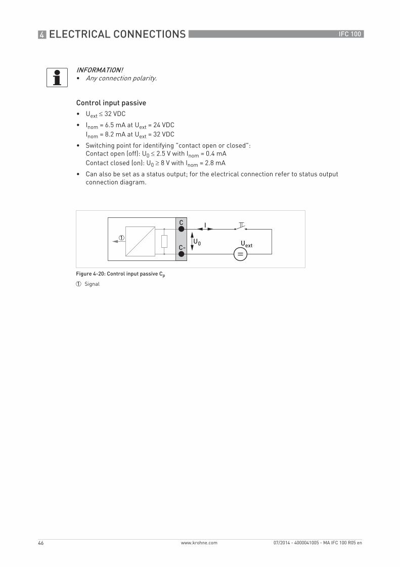
Control input passive• Uext ≤ 32 VDC
• Inom = 6.5 mA at Uext = 24 VDCInom = 8.2 mA at Uext = 32 VDC
• Switching point for identifying "contact open or closed":Contact open (off): U0 ≤ 2.5 V with Inom = 0.4 mAContact closed (on): U0 ≥ 8 V with Inom = 2.8 mA
• Can also be set as a status output; for the electrical connection refer to status output connection diagram.
INFORMATION!• Any connection polarity.
Figure 4-20: Control input passive Cp
1 Signal
ELECTRICAL CONNECTIONS 4
47
IFC 100
www.krohne.com07/2014 - 4000041005 - MA IFC 100 R05 en
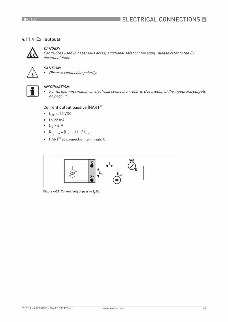
4.11.4 Ex i outputs
Current output passive (HART®)• Uext ≤ 32 VDC
• I ≤ 22 mA• U0 ≥ 4 V
• RL, min = (Uext - U0) / Imax
• HART® at connection terminals C
DANGER!For devices used in hazardous areas, additional safety notes apply; please refer to the Ex documentation.
CAUTION!• Observe connection polarity.
INFORMATION!• For further information on electrical connection refer to Description of the inputs and outputs
on page 36.
Figure 4-21: Current output passive Ip Exi
4 ELECTRICAL CONNECTIONS
48
IFC 100
www.krohne.com 07/2014 - 4000041005 - MA IFC 100 R05 en
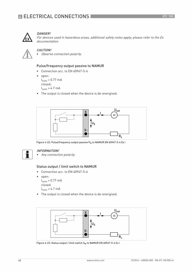
Pulse/frequency output passive to NAMUR• Connection acc. to EN 60947-5-6• open:
Inom = 0.77 mAclosed:Inom = 4.7 mA
• The output is closed when the device is de-energised.
Status output / limit switch to NAMUR• Connection acc. to EN 60947-5-6• open:
Inom = 0.77 mAclosed:Inom = 4.7 mA
• The output is closed when the device is de-energised.
DANGER!For devices used in hazardous areas, additional safety notes apply; please refer to the Ex documentation.
CAUTION!• Observe connection polarity.
Figure 4-22: Pulse/frequency output passive PN to NAMUR EN 60947-5-6 Ex i
INFORMATION!• Any connection polarity.
Figure 4-23: Status output / limit switch SN to NAMUR EN 60947-5-6 Ex i
ELECTRICAL CONNECTIONS 4
49
IFC 100
www.krohne.com07/2014 - 4000041005 - MA IFC 100 R05 en
4.11.5 HART® connection
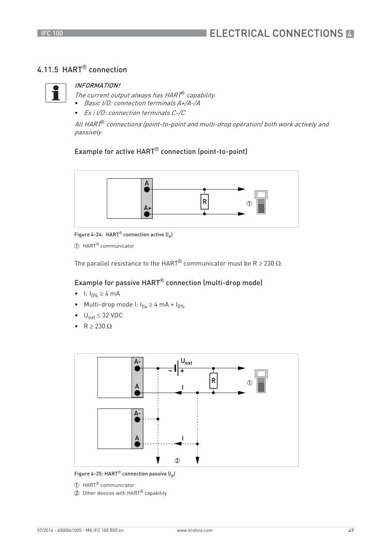
Example for active HART® connection (point-to-point)
The parallel resistance to the HART® communicator must be R ≥ 230 Ω.
Example for passive HART® connection (multi-drop mode)• I: I0% ≥ 4 mA
• Multi-drop mode I: Ifix ≥ 4 mA = I0%
• Uext ≤ 32 VDC
• R ≥ 230 Ω
INFORMATION!The current output always has HART® capability.• Basic I/O: connection terminals A+/A-/A• Ex i I/O: connection terminals C-/C
All HART® connections (point-to-point and multi-drop operation) both work actively and passively.
Figure 4-24: HART® connection active (Ia)
1 HART® communicator
Figure 4-25: HART® connection passive (Ip)
1 HART® communicator
2 Other devices with HART® capability
5 START-UP
50
IFC 100
www.krohne.com 07/2014 - 4000041005 - MA IFC 100 R05 en
5.1 Switching on the power
Before connecting to power, please check that the system has been correctly installed. This includes:• The device must be mechanically safe and mounted in compliance with the regulations.• The power connections must have been made in compliance with the regulations.• The electrical terminal compartments must be secured and the covers have been screwed
on.• Check that the electrical operating data of the power supply are correct.
• Switching on the power.
5.2 Starting the signal converter
The measuring device, consisting of the measuring sensor and the signal converter, is supplied ready for operation. All operating data have been set at the factory in accordance with your order specifications.
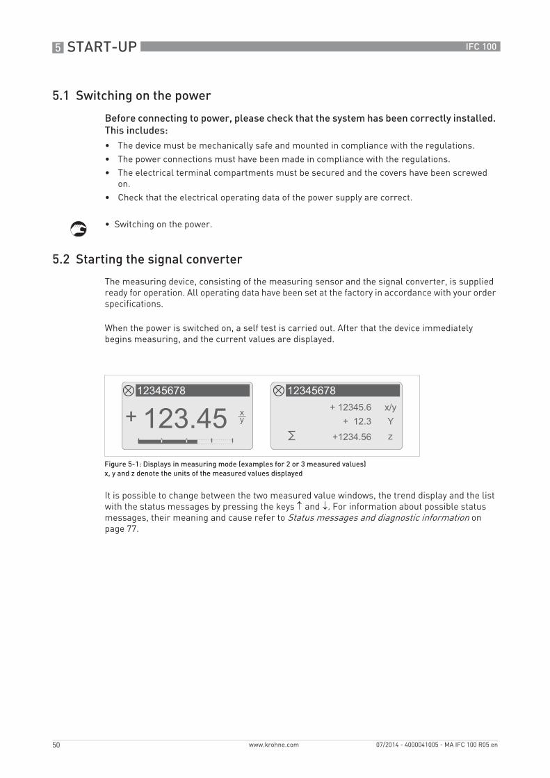
When the power is switched on, a self test is carried out. After that the device immediately begins measuring, and the current values are displayed.
It is possible to change between the two measured value windows, the trend display and the list with the status messages by pressing the keys ↑ and ↓. For information about possible status messages, their meaning and cause refer to Status messages and diagnostic information on page 77.
Figure 5-1: Displays in measuring mode (examples for 2 or 3 measured values)x, y and z denote the units of the measured values displayed
OPERATION 6
51
IFC 100
www.krohne.com07/2014 - 4000041005 - MA IFC 100 R05 en
6.1 Display and operating elements
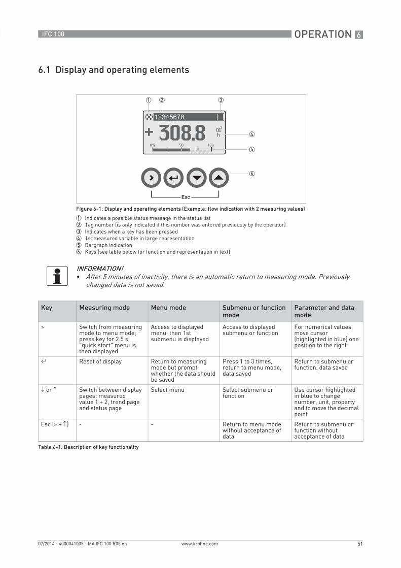
Figure 6-1: Display and operating elements (Example: flow indication with 2 measuring values)
1 Indicates a possible status message in the status list2 Tag number (is only indicated if this number was entered previously by the operator)3 Indicates when a key has been pressed4 1st measured variable in large representation5 Bargraph indication6 Keys (see table below for function and representation in text)
INFORMATION!• After 5 minutes of inactivity, there is an automatic return to measuring mode. Previously
changed data is not saved.
Key Measuring mode Menu mode Submenu or function mode
Parameter and data mode
> Switch from measuring mode to menu mode; press key for 2.5 s, "quick start" menu is then displayed
Access to displayed menu, then 1st submenu is displayed
Access to displayed submenu or function
For numerical values, move cursor (highlighted in blue) one position to the right
^ Reset of display Return to measuring mode but prompt whether the data should be saved
Press 1 to 3 times, return to menu mode, data saved
Return to submenu or function, data saved
↓ or ↑ Switch between display pages: measured value 1 + 2, trend page and status page
Select menu Select submenu or function
Use cursor highlighted in blue to change number, unit, property and to move the decimal point
Esc (> + ↑) - - Return to menu mode without acceptance of data
Return to submenu or function without acceptance of data
Table 6-1: Description of key functionality
6 OPERATION
52
IFC 100
www.krohne.com 07/2014 - 4000041005 - MA IFC 100 R05 en
6.1.1 Display in measuring mode with 2 or 3 measured values
6.1.2 Display for selection of sub-menu and functions, 3 lines
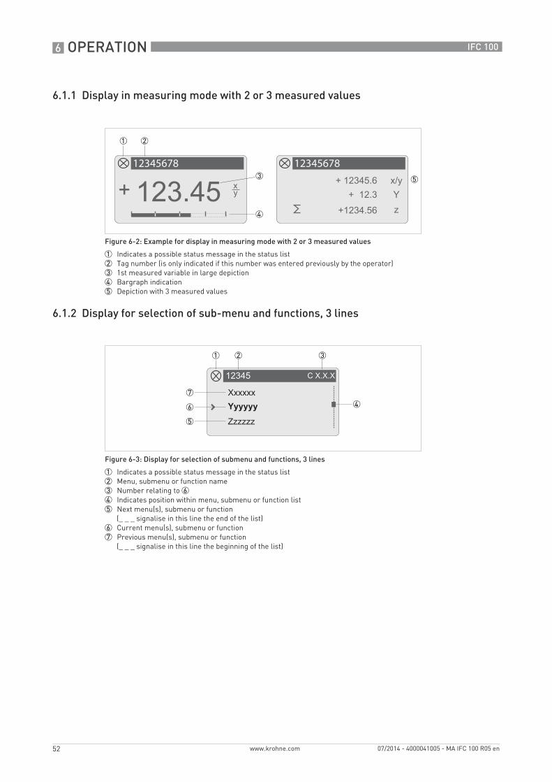
Figure 6-2: Example for display in measuring mode with 2 or 3 measured values
1 Indicates a possible status message in the status list2 Tag number (is only indicated if this number was entered previously by the operator)3 1st measured variable in large depiction4 Bargraph indication5 Depiction with 3 measured values
Figure 6-3: Display for selection of submenu and functions, 3 lines
1 Indicates a possible status message in the status list2 Menu, submenu or function name3 Number relating to 64 Indicates position within menu, submenu or function list5 Next menu(s), submenu or function
(_ _ _ signalise in this line the end of the list)6 Current menu(s), submenu or function7 Previous menu(s), submenu or function
(_ _ _ signalise in this line the beginning of the list)
OPERATION 6
53
IFC 100
www.krohne.com07/2014 - 4000041005 - MA IFC 100 R05 en
6.1.3 Display when setting parameters, 4 lines
6.1.4 Display when previewing parameters, 4 lines
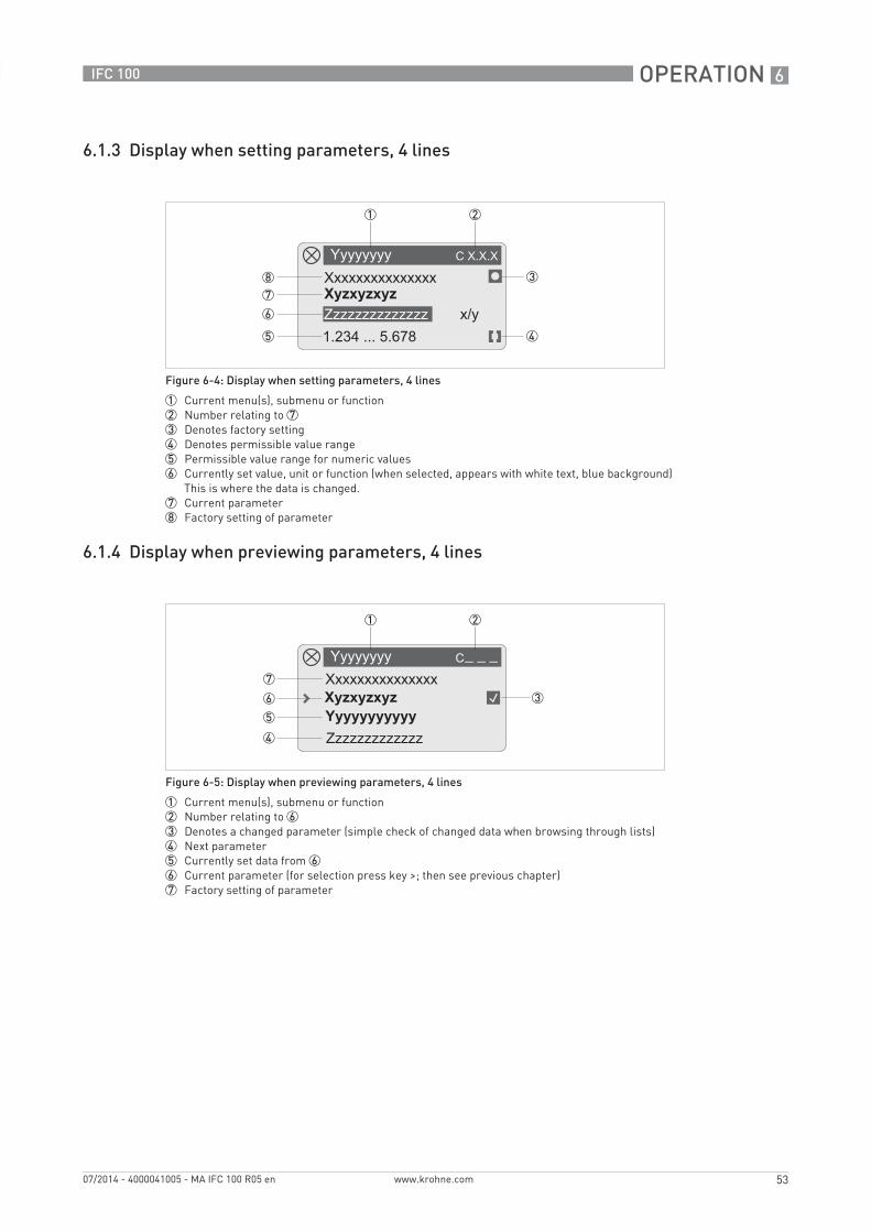
Figure 6-4: Display when setting parameters, 4 lines
1 Current menu(s), submenu or function 2 Number relating to 73 Denotes factory setting4 Denotes permissible value range5 Permissible value range for numeric values6 Currently set value, unit or function (when selected, appears with white text, blue background)
This is where the data is changed.7 Current parameter8 Factory setting of parameter
Figure 6-5: Display when previewing parameters, 4 lines
1 Current menu(s), submenu or function 2 Number relating to 63 Denotes a changed parameter (simple check of changed data when browsing through lists)4 Next parameter5 Currently set data from 66 Current parameter (for selection press key >; then see previous chapter)7 Factory setting of parameter
6 OPERATION
54
IFC 100
www.krohne.com 07/2014 - 4000041005 - MA IFC 100 R05 en
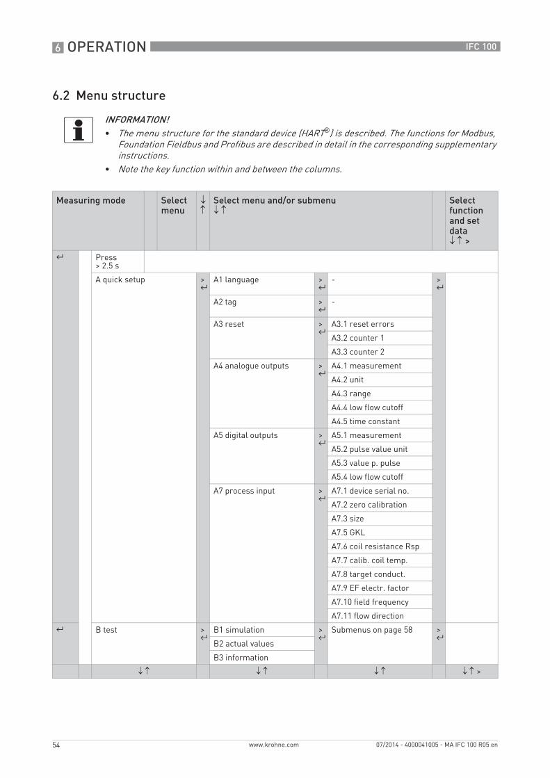
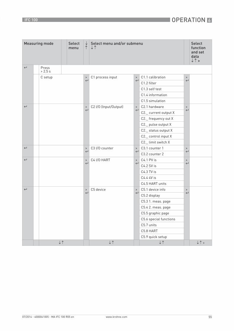
6.2 Menu structure
INFORMATION!• The menu structure for the standard device (HART®) is described. The functions for Modbus,
Foundation Fieldbus and Profibus are described in detail in the corresponding supplementary instructions.
• Note the key function within and between the columns.
Measuring mode Select menu
↓ ↑
Select menu and/or submenu↓ ↑
Select function and set data↓ ↑ >
^ Press > 2.5 s
A quick setup > ^
A1 language > ^
- > ^
A2 tag > ^
-
A3 reset > ^
A3.1 reset errors
A3.2 counter 1
A3.3 counter 2
A4 analogue outputs > ^
A4.1 measurement
A4.2 unit
A4.3 range
A4.4 low flow cutoff
A4.5 time constant
A5 digital outputs > ^
A5.1 measurement
A5.2 pulse value unit
A5.3 value p. pulse
A5.4 low flow cutoff
A7 process input > ^
A7.1 device serial no.
A7.2 zero calibration
A7.3 size
A7.5 GKL
A7.6 coil resistance Rsp
A7.7 calib. coil temp.
A7.8 target conduct.
A7.9 EF electr. factor
A7.10 field frequency
A7.11 flow direction
^ B test > ^
B1 simulation > ^
Submenus on page 58 > ^
B2 actual values
B3 information
↓ ↑ ↓ ↑ ↓ ↑ ↓ ↑ >
OPERATION 6
55
IFC 100
www.krohne.com07/2014 - 4000041005 - MA IFC 100 R05 en
Measuring mode Select menu
↓ ↑
Select menu and/or submenu↓ ↑
Select function and set data↓ ↑ >
^ Press > 2.5 s
C setup > ^
C1 process input > ^
C1.1 calibration > ^
C1.2 filter
C1.3 self test
C1.4 information
C1.5 simulation
^ > ^
C2 I/O (Input/Output) > ^
C2.1 hardware > ^
C2._ current output X
C2._ frequency out X
C2._ pulse output X
C2._ status output X
C2._ control input X
C2._ limit switch X
^ > ^
C3 I/O counter > ^
C3.1 counter 1 > ^
C3.2 counter 2
^ > ^
C4 I/O HART > ^
C4.1 PV is > ^
C4.2 SV is
C4.3 TV is
C4.4 4V is
C4.5 HART units
^ > ^
C5 device > ^
C5.1 device info > ^
C5.2 display
C5.3 1. meas. page
C5.4 2. meas. page
C5.5 graphic page
C5.6 special functions
C5.7 units
C5.8 HART
C5.9 quick setup
↓ ↑ ↓ ↑ ↓ ↑ ↓ ↑ >
6 OPERATION
56
IFC 100
www.krohne.com 07/2014 - 4000041005 - MA IFC 100 R05 en
6.3 Function tables
6.3.1 Menu A, quick setup
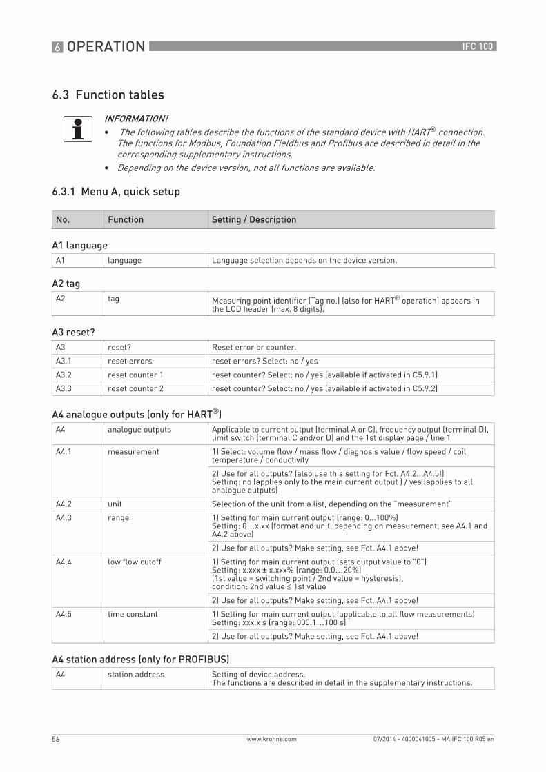
INFORMATION!• The following tables describe the functions of the standard device with HART® connection.
The functions for Modbus, Foundation Fieldbus and Profibus are described in detail in the corresponding supplementary instructions.
• Depending on the device version, not all functions are available.
No. Function Setting / Description
A1 languageA1 language Language selection depends on the device version.
A2 tagA2 tag Measuring point identifier (Tag no.) (also for HART® operation) appears in
the LCD header (max. 8 digits).
A3 reset?A3 reset? Reset error or counter.
A3.1 reset errors reset errors? Select: no / yes
A3.2 reset counter 1 reset counter? Select: no / yes (available if activated in C5.9.1)
A3.3 reset counter 2 reset counter? Select: no / yes (available if activated in C5.9.2)
A4 analogue outputs (only for HART®)A4 analogue outputs Applicable to current output (terminal A or C), frequency output (terminal D),
limit switch (terminal C and/or D) and the 1st display page / line 1
A4.1 measurement 1) Select: volume flow / mass flow / diagnosis value / flow speed / coil temperature / conductivity
2) Use for all outputs? (also use this setting for Fct. A4.2...A4.5!)Setting: no (applies only to the main current output ) / yes (applies to all analogue outputs)
A4.2 unit Selection of the unit from a list, depending on the "measurement"
A4.3 range 1) Setting for main current output (range: 0...100%)Setting: 0…x.xx (format and unit, depending on measurement, see A4.1 and A4.2 above)
2) Use for all outputs? Make setting, see Fct. A4.1 above!
A4.4 low flow cutoff 1) Setting for main current output (sets output value to "0")Setting: x.xxx ± x.xxx% (range: 0.0…20%) (1st value = switching point / 2nd value = hysteresis), condition: 2nd value ≤ 1st value
2) Use for all outputs? Make setting, see Fct. A4.1 above!
A4.5 time constant 1) Setting for main current output (applicable to all flow measurements)Setting: xxx.x s (range: 000.1…100 s)
2) Use for all outputs? Make setting, see Fct. A4.1 above!
A4 station address (only for PROFIBUS)A4 station address Setting of device address.
The functions are described in detail in the supplementary instructions.

OPERATION 6
57
IFC 100
www.krohne.com07/2014 - 4000041005 - MA IFC 100 R05 en
A4 slave address (only for MODBUS)A4 slave address Setting of device address.
The functions are described in detail in the supplementary instructions.
A5 digital outputs (only for HART®)A5 digital outputs Valid for pulse output (terminal D) and counter 1.
A5.1 measurement 1) Select the "measurement": volume flow / mass flow
2) Use for all outputs? (also use this setting for Fct. A5.2...A5.4!)Setting: no (only for pulse output D) / yes (for all digital outputs)
A5.2 pulse value unit Selection of the unit from a list, depending on the measurement
A5.3 value p. pulse 1) Setting for pulse output D (volume or mass value per pulse)Setting: xxx.xxx in l or kg or in the unit selected in A5.2
2) Use for all outputs? Make setting, see Fct. A5.1 above!
A5.4 low flow cutoff 1) Setting for pulse output D (sets output value to "0")Setting: x.xxx ± x.xxx% (range: 0.0…20%)(1st value = switching point / 2nd value = hysteresis), condition: 2nd value ≤ 1st value
2) Use for all outputs? Make setting, see Fct. A5.1 above!
A7 process inputA7.1 device serial no. Shows the serial no. of the system.
The following process input parameters are only available, if the quick access has been activated in the menu "setup / device / quick setup".
A7.2 zero calibration Display of actual zero calibration value.
Query: calibrate zero?
Settings see Fct. C1.1.1.
A7.3 size Select from the size table.
A7.5 GKL Set value acc. to information on nameplate; range: 0.5…20
A7.6 coil resistance Rsp Field coil resistance at 20°C; range: 10.00...220 Ω
A7.7 calib. coil temp. The coil temperature is derived from the coil resistance at the reference temperature.
Settings see Fct. C1.1.8.
A7.8 target conduct. Reference value for on-site calibration; range: 1.000...50000 μS/cm
A7.9 EF electr. factor For calculation of the conductivity based on the electrode impedance.
Settings see Fct. C1.1.11.
A7.10 field frequency Setting as on the nameplate of the measuring sensor =line frequency x value (from the following list):
1/2; 1/4; 1/6; 1/8; 1/12; 1/18; 1/36; 1/50
A7.11 flow direction Define the polarity of the flow direction.
Select:normal direction (according to the arrow on the measuring sensor) /reverse direction (in the opposite direction to the arrow)
No. Function Setting / Description
6 OPERATION
58
IFC 100
www.krohne.com 07/2014 - 4000041005 - MA IFC 100 R05 en
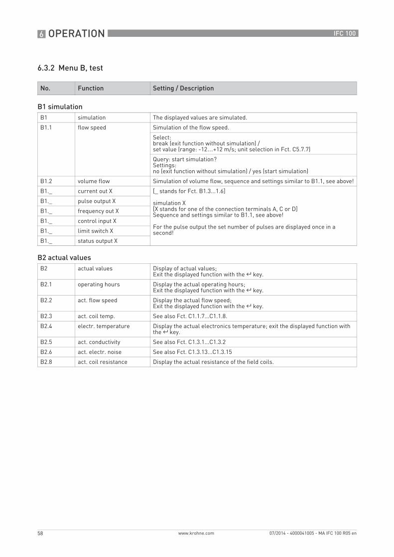
6.3.2 Menu B, test
No. Function Setting / Description
B1 simulationB1 simulation The displayed values are simulated.
B1.1 flow speed Simulation of the flow speed.
Select:break (exit function without simulation) /set value (range: -12…+12 m/s; unit selection in Fct. C5.7.7)
Query: start simulation?Settings:no (exit function without simulation) / yes (start simulation)
B1.2 volume flow Simulation of volume flow, sequence and settings similar to B1.1, see above!
B1._ current out X [_ stands for Fct. B1.3...1.6]
simulation X[X stands for one of the connection terminals A, C or D]Sequence and settings similar to B1.1, see above!
For the pulse output the set number of pulses are displayed once in a second!
B1._ pulse output X
B1._ frequency out X
B1._ control input X
B1._ limit switch X
B1._ status output X
B2 actual valuesB2 actual values Display of actual values;
Exit the displayed function with the ^ key.
B2.1 operating hours Display the actual operating hours;Exit the displayed function with the ^ key.
B2.2 act. flow speed Display the actual flow speed;Exit the displayed function with the ^ key.
B2.3 act. coil temp. See also Fct. C1.1.7...C1.1.8.
B2.4 electr. temperature Display the actual electronics temperature; exit the displayed function with the ^ key.
B2.5 act. conductivity See also Fct. C1.3.1...C1.3.2
B2.6 act. electr. noise See also Fct. C1.3.13...C1.3.15
B2.8 act. coil resistance Display the actual resistance of the field coils.
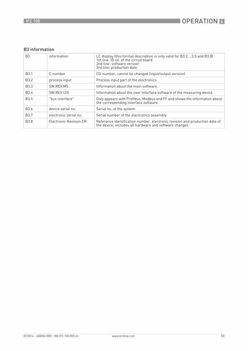
OPERATION 6
59
IFC 100
www.krohne.com07/2014 - 4000041005 - MA IFC 100 R05 en
B3 informationB3 information LC display (this format description is only valid for B3.2....3.5 and B3.8)
1st line: ID no. of the circuit board2nd line: software version3rd line: production date
B3.1 C number CG number, cannot be changed (input/output version)
B3.2 process input Process input part of the electronics
B3.3 SW.REV.MS Information about the main software
B3.4 SW.REV.UIS Information about the user interface software of the measuring device
B3.5 "bus interface" Only appears with Profibus, Modbus and FF and shows the information about the corresponding interface software.
B3.6 device serial no. Serial no. of the system
B3.7 electronic serial no. Serial number of the electronics assembly
B3.8 Electronic Revision ER Reference identification number, electronic revision and production date of the device; includes all hardware and software changes
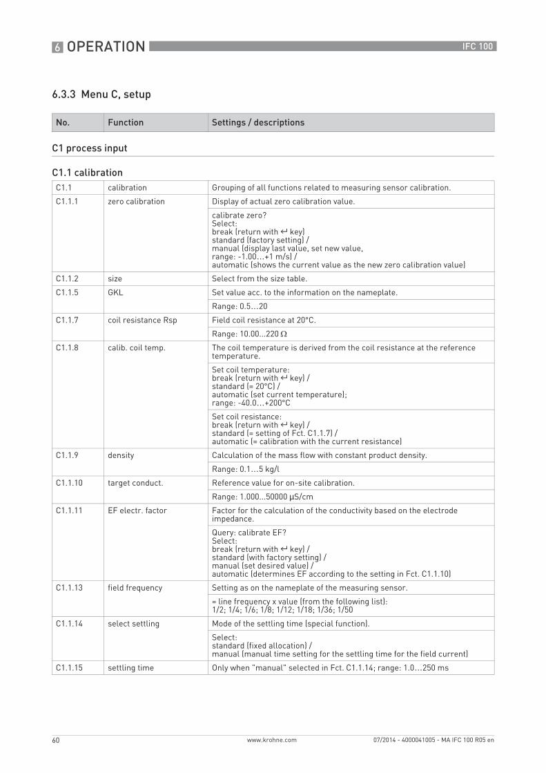
6 OPERATION
60
IFC 100
www.krohne.com 07/2014 - 4000041005 - MA IFC 100 R05 en
6.3.3 Menu C, setup
No. Function Settings / descriptions
C1 process input
C1.1 calibrationC1.1 calibration Grouping of all functions related to measuring sensor calibration.
C1.1.1 zero calibration Display of actual zero calibration value.
calibrate zero?Select:break (return with ^ key)standard (factory setting) /manual (display last value, set new value,range: -1.00…+1 m/s) / automatic (shows the current value as the new zero calibration value)
C1.1.2 size Select from the size table.
C1.1.5 GKL Set value acc. to the information on the nameplate.
Range: 0.5…20
C1.1.7 coil resistance Rsp Field coil resistance at 20°C.
Range: 10.00...220 Ω
C1.1.8 calib. coil temp. The coil temperature is derived from the coil resistance at the reference temperature.
Set coil temperature:break (return with ^ key) /standard (= 20°C) /automatic (set current temperature);range: -40.0…+200°C
Set coil resistance:break (return with ^ key) /standard (= setting of Fct. C1.1.7) /automatic (= calibration with the current resistance)
C1.1.9 density Calculation of the mass flow with constant product density.
Range: 0.1…5 kg/l
C1.1.10 target conduct. Reference value for on-site calibration.
Range: 1.000...50000 µS/cm
C1.1.11 EF electr. factor Factor for the calculation of the conductivity based on the electrode impedance.
Query: calibrate EF?Select:break (return with ^ key) /standard (with factory setting) /manual (set desired value) /automatic (determines EF according to the setting in Fct. C1.1.10)
C1.1.13 field frequency Setting as on the nameplate of the measuring sensor.
= line frequency x value (from the following list):1/2; 1/4; 1/6; 1/8; 1/12; 1/18; 1/36; 1/50
C1.1.14 select settling Mode of the settling time (special function).
Select:standard (fixed allocation) / manual (manual time setting for the settling time for the field current)
C1.1.15 settling time Only when "manual" selected in Fct. C1.1.14; range: 1.0…250 ms
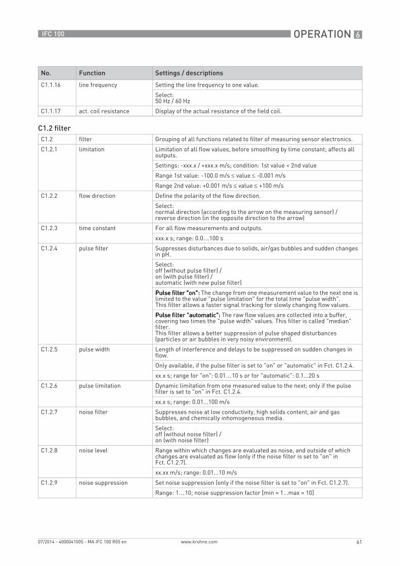
OPERATION 6
61
IFC 100
www.krohne.com07/2014 - 4000041005 - MA IFC 100 R05 en
C1.1.16 line frequency Setting the line frequency to one value.
Select:50 Hz / 60 Hz
C1.1.17 act. coil resistance Display of the actual resistance of the field coil.
C1.2 filterC1.2 filter Grouping of all functions related to filter of measuring sensor electronics.
C1.2.1 limitation Limitation of all flow values, before smoothing by time constant; affects all outputs.
Settings: -xxx.x / +xxx.x m/s; condition: 1st value < 2nd value
Range 1st value: -100.0 m/s ≤ value ≤ -0.001 m/s
Range 2nd value: +0.001 m/s ≤ value ≤ +100 m/s
C1.2.2 flow direction Define the polarity of the flow direction.
Select:normal direction (according to the arrow on the measuring sensor) /reverse direction (in the opposite direction to the arrow)
C1.2.3 time constant For all flow measurements and outputs.
xxx.x s; range: 0.0…100 s
C1.2.4 pulse filter Suppresses disturbances due to solids, air/gas bubbles and sudden changes in pH.
Select:off (without pulse filter) /on (with pulse filter) /automatic (with new pulse filter)
Pulse filter "on":Pulse filter "on":Pulse filter "on":Pulse filter "on": The change from one measurement value to the next one is limited to the value "pulse limitation" for the total time "pulse width".This filter allows a faster signal tracking for slowly changing flow values.
Pulse filter "automatic":Pulse filter "automatic":Pulse filter "automatic":Pulse filter "automatic": The raw flow values are collected into a buffer, covering two times the "pulse width" values. This filter is called "median" filter.This filter allows a better suppression of pulse shaped disturbances (particles or air bubbles in very noisy environment).
C1.2.5 pulse width Length of interference and delays to be suppressed on sudden changes in flow.
Only available, if the pulse filter is set to "on" or "automatic" in Fct. C1.2.4.
xx.x s; range for "on": 0.01…10 s or for "automatic": 0.1...20 s
C1.2.6 pulse limitation Dynamic limitation from one measured value to the next; only if the pulse filter is set to "on" in Fct. C1.2.4.
xx.x s; range: 0.01...100 m/s
C1.2.7 noise filter Suppresses noise at low conductivity, high solids content, air and gas bubbles, and chemically inhomogeneous media.
Select:off (without noise filter) /on (with noise filter)
C1.2.8 noise level Range within which changes are evaluated as noise, and outside of which changes are evaluated as flow (only if the noise filter is set to "on" in Fct. C1.2.7).
xx.xx m/s; range: 0.01...10 m/s
C1.2.9 noise suppression Set noise suppression (only if the noise filter is set to "on" in Fct. C1.2.7).
Range: 1…10; noise suppression factor [min = 1...max = 10]
No. Function Settings / descriptions
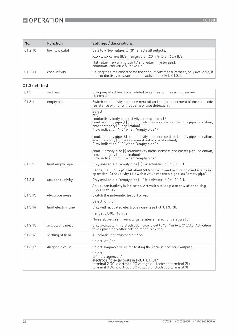
6 OPERATION
62
IFC 100
www.krohne.com 07/2014 - 4000041005 - MA IFC 100 R05 en
C1.2.10 low flow cutoff Sets low flow values to "0"; affects all outputs.
x.xxx ± x.xxx m/s (ft/s); range: 0.0…20 m/s (0.0...65.6 ft/s)
(1st value = switching point / 2nd value = hysteresis), condition: 2nd value ≤ 1st value
C1.2.11 conductivity Setting the time constant for the conductivity measurement; only available, if the conductivity measurement is activated in Fct. C1.3.1.
C1.3 self testC1.3 self test Grouping of all functions related to self test of measuring sensor
electronics.
C1.3.1 empty pipe Switch conductivity measurement off and on (measurement of the electrode resistance with or without empty pipe detection).
Select:off /conductivity (only conductivity measurement) /cond. + empty pipe [F] (conductivity measurement and empty pipe indication, error category [F] application);Flow indication "= 0" when "empty pipe" /
cond. + empty pipe [S] (conductivity measurement and empty pipe indication, error category [S] measurement out of specification);Flow indication "= 0" when "empty pipe" /
cond. + empty pipe [I] (conductivity measurement and empty pipe indication, error category [I] information);Flow indication "= 0" when "empty pipe"
C1.3.2 limit empty pipe Only available if "empty pipe [..]" is activated in Fct. C1.3.1.
Range: 0.0…9999 μS (set about 50% of the lowest occurring conductivity in operation. Conductivity below this value means a signal as "empty pipe".
C1.3.3 act. conductivity Only available if "empty pipe [..]" is activated in Fct. C1.3.1.
Actual conductivity is indicated. Activation takes place only after setting mode is exited!
C1.3.13 electrode noise Switch the automatic test off or on.
Select: off / on
C1.3.14 limit electr. noise Only with activated electrode noise (see Fct. C1.3.13).
Range: 0.000…12 m/s
Noise above this threshold generates an error of category [S].
C1.3.15 act. electr. noise Only available if the electrode noise is set to "on" in Fct. C1.3.13. Activation takes place only after setting mode is exited!
C1.3.16 settling of field Automatic test switched off / on.
Select: off / on
C1.3.17 diagnosis value Select diagnosis value for testing the various analogue outputs.
Select:off (no diagnosis) /electrode noise (activate in Fct. C1.3.13) /terminal 2 DC (electrode DC voltage at electrode terminal 2) /terminal 3 DC (electrode DC voltage at electrode terminal 3)
No. Function Settings / descriptions
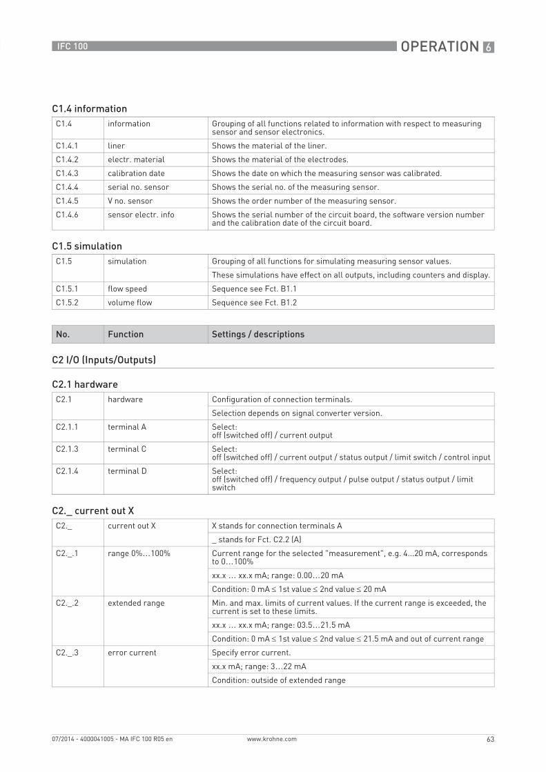
OPERATION 6
63
IFC 100
www.krohne.com07/2014 - 4000041005 - MA IFC 100 R05 en
C1.4 informationC1.4 information Grouping of all functions related to information with respect to measuring
sensor and sensor electronics.
C1.4.1 liner Shows the material of the liner.
C1.4.2 electr. material Shows the material of the electrodes.
C1.4.3 calibration date Shows the date on which the measuring sensor was calibrated.
C1.4.4 serial no. sensor Shows the serial no. of the measuring sensor.
C1.4.5 V no. sensor Shows the order number of the measuring sensor.
C1.4.6 sensor electr. info Shows the serial number of the circuit board, the software version number and the calibration date of the circuit board.
C1.5 simulationC1.5 simulation Grouping of all functions for simulating measuring sensor values.
These simulations have effect on all outputs, including counters and display.
C1.5.1 flow speed Sequence see Fct. B1.1
C1.5.2 volume flow Sequence see Fct. B1.2
No. Function Settings / descriptions
C2 I/O (Inputs/Outputs)
C2.1 hardwareC2.1 hardware Configuration of connection terminals.
Selection depends on signal converter version.
C2.1.1 terminal A Select:off (switched off) / current output
C2.1.3 terminal C Select:off (switched off) / current output / status output / limit switch / control input
C2.1.4 terminal D Select:off (switched off) / frequency output / pulse output / status output / limit switch
C2._ current out XC2._ current out X X stands for connection terminals A
_ stands for Fct. C2.2 (A)
C2._.1 range 0%…100% Current range for the selected "measurement", e.g. 4...20 mA, corresponds to 0…100%
xx.x … xx.x mA; range: 0.00…20 mA
Condition: 0 mA ≤ 1st value ≤ 2nd value ≤ 20 mA
C2._.2 extended range Min. and max. limits of current values. If the current range is exceeded, the current is set to these limits.
xx.x … xx.x mA; range: 03.5…21.5 mA
Condition: 0 mA ≤ 1st value ≤ 2nd value ≤ 21.5 mA and out of current range
C2._.3 error current Specify error current.
xx.x mA; range: 3…22 mA
Condition: outside of extended range
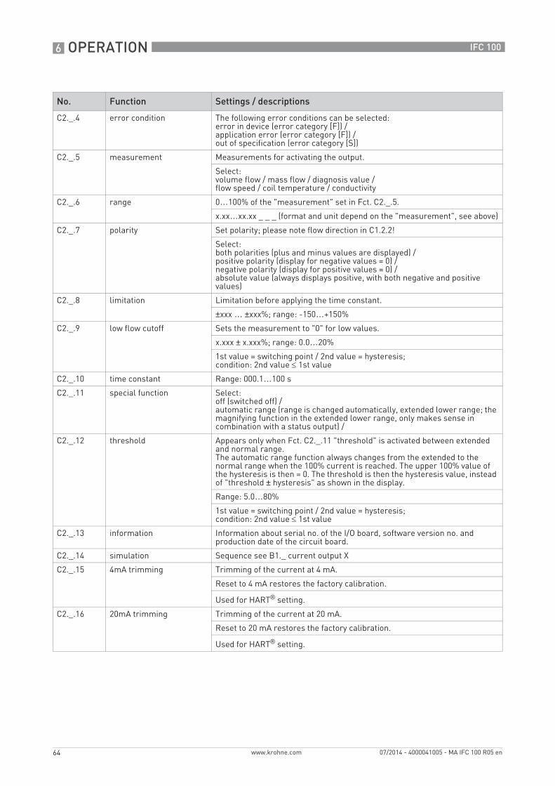
6 OPERATION
64
IFC 100
www.krohne.com 07/2014 - 4000041005 - MA IFC 100 R05 en
C2._.4 error condition The following error conditions can be selected:error in device (error category [F]) /application error (error category [F]) /out of specification (error category [S])
C2._.5 measurement Measurements for activating the output.
Select:volume flow / mass flow / diagnosis value /flow speed / coil temperature / conductivity
C2._.6 range 0…100% of the "measurement" set in Fct. C2._.5.
x.xx…xx.xx _ _ _ (format and unit depend on the "measurement", see above)
C2._.7 polarity Set polarity; please note flow direction in C1.2.2!
Select:both polarities (plus and minus values are displayed) /positive polarity (display for negative values = 0) /negative polarity (display for positive values = 0) /absolute value (always displays positive, with both negative and positive values)
C2._.8 limitation Limitation before applying the time constant.
±xxx … ±xxx%; range: -150…+150%
C2._.9 low flow cutoff Sets the measurement to "0" for low values.
x.xxx ± x.xxx%; range: 0.0…20%
1st value = switching point / 2nd value = hysteresis;condition: 2nd value ≤ 1st value
C2._.10 time constant Range: 000.1…100 s
C2._.11 special function Select:off (switched off) /automatic range (range is changed automatically, extended lower range; the magnifying function in the extended lower range, only makes sense in combination with a status output) /
C2._.12 threshold Appears only when Fct. C2._.11 "threshold" is activated between extended and normal range.The automatic range function always changes from the extended to the normal range when the 100% current is reached. The upper 100% value of the hysteresis is then = 0. The threshold is then the hysteresis value, instead of "threshold ± hysteresis" as shown in the display.
Range: 5.0…80%
1st value = switching point / 2nd value = hysteresis;condition: 2nd value ≤ 1st value
C2._.13 information Information about serial no. of the I/O board, software version no. and production date of the circuit board.
C2._.14 simulation Sequence see B1._ current output X
C2._.15 4mA trimming Trimming of the current at 4 mA.
Reset to 4 mA restores the factory calibration.
Used for HART® setting.
C2._.16 20mA trimming Trimming of the current at 20 mA.
Reset to 20 mA restores the factory calibration.
Used for HART® setting.
No. Function Settings / descriptions
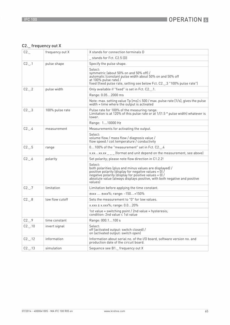
OPERATION 6
65
IFC 100
www.krohne.com07/2014 - 4000041005 - MA IFC 100 R05 en
C2._ frequency out XC2._ frequency out X X stands for connection terminals D
_ stands for Fct. C2.5 (D)
C2._.1 pulse shape Specify the pulse shape.
Select:symmetric (about 50% on and 50% off) /automatic (constant pulse width about 50% on and 50% offat 100% pulse rate) /fixed (fixed pulse rate, setting see below Fct. C2._.3 "100% pulse rate")
C2._.2 pulse width Only available if "fixed" is set in Fct. C2._.1.
Range: 0.05…2000 ms
Note: max. setting value Tp [ms] ≤ 500 / max. pulse rate [1/s], gives the pulse width = time where the output is activated
C2._.3 100% pulse rate Pulse rate for 100% of the measuring range.Limitation is at 120% of this pulse rate or at 1/(1.5 * pulse width) whatever is lower.
Range: 1…10000 Hz
C2._.4 measurement Measurements for activating the output.
Select:volume flow / mass flow / diagnosis value /flow speed / coil temperature / conductivity
C2._.5 range 0…100% of the "measurement" set in Fct. C2._.4
x.xx…xx.xx _ _ _ (format and unit depend on the measurement, see above)
C2._.6 polarity Set polarity; please note flow direction in C1.2.2!
Select:both polarities (plus and minus values are displayed) /positive polarity (display for negative values = 0) /negative polarity (display for positive values = 0) /absolute value (always displays positive, with both negative and positive values)
C2._.7 limitation Limitation before applying the time constant.
±xxx … ±xxx%; range: -150…+150%
C2._.8 low flow cutoff Sets the measurement to "0" for low values.
x.xxx ± x.xxx%; range: 0.0…20%
1st value = switching point / 2nd value = hysteresis;condition: 2nd value ≤ 1st value
C2._.9 time constant Range: 000.1…100 s
C2._.10 invert signal Select:off (activated output: switch closed) /on (activated output: switch open)
C2._.12 information Information about serial no. of the I/O board, software version no. and production date of the circuit board.
C2._.13 simulation Sequence see B1._ frequency out X
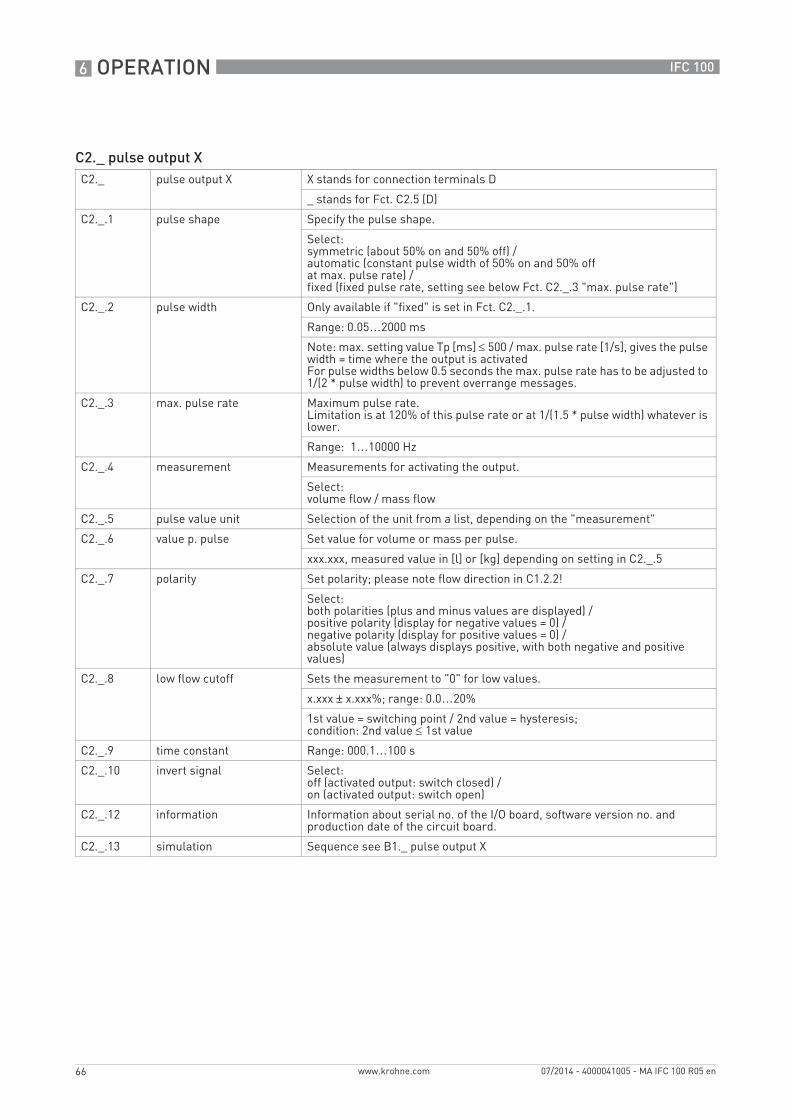
6 OPERATION
66
IFC 100
www.krohne.com 07/2014 - 4000041005 - MA IFC 100 R05 en
C2._ pulse output XC2._ pulse output X X stands for connection terminals D
_ stands for Fct. C2.5 (D)
C2._.1 pulse shape Specify the pulse shape.
Select:symmetric (about 50% on and 50% off) /automatic (constant pulse width of 50% on and 50% offat max. pulse rate) /fixed (fixed pulse rate, setting see below Fct. C2._.3 "max. pulse rate")
C2._.2 pulse width Only available if "fixed" is set in Fct. C2._.1.
Range: 0.05…2000 ms
Note: max. setting value Tp [ms] ≤ 500 / max. pulse rate [1/s], gives the pulse width = time where the output is activatedFor pulse widths below 0.5 seconds the max. pulse rate has to be adjusted to 1/(2 * pulse width) to prevent overrange messages.
C2._.3 max. pulse rate Maximum pulse rate.Limitation is at 120% of this pulse rate or at 1/(1.5 * pulse width) whatever is lower.
Range: 1…10000 Hz
C2._.4 measurement Measurements for activating the output.
Select:volume flow / mass flow
C2._.5 pulse value unit Selection of the unit from a list, depending on the "measurement"
C2._.6 value p. pulse Set value for volume or mass per pulse.
xxx.xxx, measured value in [l] or [kg] depending on setting in C2._.5
C2._.7 polarity Set polarity; please note flow direction in C1.2.2!
Select:both polarities (plus and minus values are displayed) /positive polarity (display for negative values = 0) /negative polarity (display for positive values = 0) /absolute value (always displays positive, with both negative and positive values)
C2._.8 low flow cutoff Sets the measurement to "0" for low values.
x.xxx ± x.xxx%; range: 0.0…20%
1st value = switching point / 2nd value = hysteresis;condition: 2nd value ≤ 1st value
C2._.9 time constant Range: 000.1…100 s
C2._.10 invert signal Select:off (activated output: switch closed) /on (activated output: switch open)
C2._.12 information Information about serial no. of the I/O board, software version no. and production date of the circuit board.
C2._.13 simulation Sequence see B1._ pulse output X
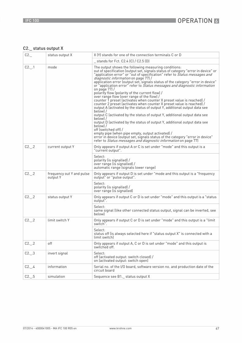
OPERATION 6
67
IFC 100
www.krohne.com07/2014 - 4000041005 - MA IFC 100 R05 en
C2._ status output XC2._ status output X X (Y) stands for one of the connection terminals C or D
_ stands for Fct. C2.4 (C) / C2.5 (D)
C2._.1 mode The output shows the following measuring conditions:out of specification (output set, signals status of category "error in device" or "application error" or "out of specification" refer to Status messages and diagnostic information on page 77) /application error (output set, signals status of the category "error in device" or "application error" refer to Status messages and diagnostic information on page 77) /polarity flow (polarity of the current flow) /over range flow (over range of the flow) /counter 1 preset (activates when counter X preset value is reached) /counter 2 preset (activates when counter X preset value is reached) /output A (activated by the status of output Y, additional output data see below) /output C (activated by the status of output Y, additional output data see below) /output D (activated by the status of output Y, additional output data see below) /off (switched off) /empty pipe (when pipe empty, output activated) /error in device (output set, signals status of the category "error in device" refer to Status messages and diagnostic information on page 77)
C2._.2 current output Y Only appears if output A or C is set under "mode" and this output is a "current output".
Select:polarity (is signalled) /over range (is signalled) /automatic range (signals lower range)
C2._.2 frequency out Y and pulse output Y
Only appears if output D is set under "mode and this output is a "frequency output" or "pulse output".
Select:polarity (is signalled) /over range (is signalled)
C2._.2 status output Y Only appears if output C or D is set under "mode" and this output is a "status output".
Select:same signal (like other connected status output, signal can be inverted, see below)
C2._.2 limit switch Y Only appears if output C or D is set under "mode" and this output is a "limit switch".
Select:status off (is always selected here if "status output X" is connected with a limit switch)
C2._.2 off Only appears if output A, C or D is set under "mode" and this output is switched off.
C2._.3 invert signal Select:off (activated output: switch closed) /on (activated output: switch open)
C2._.4 information Serial no. of the I/O board, software version no. and production date of the circuit board
C2._.5 simulation Sequence see B1._ status output X
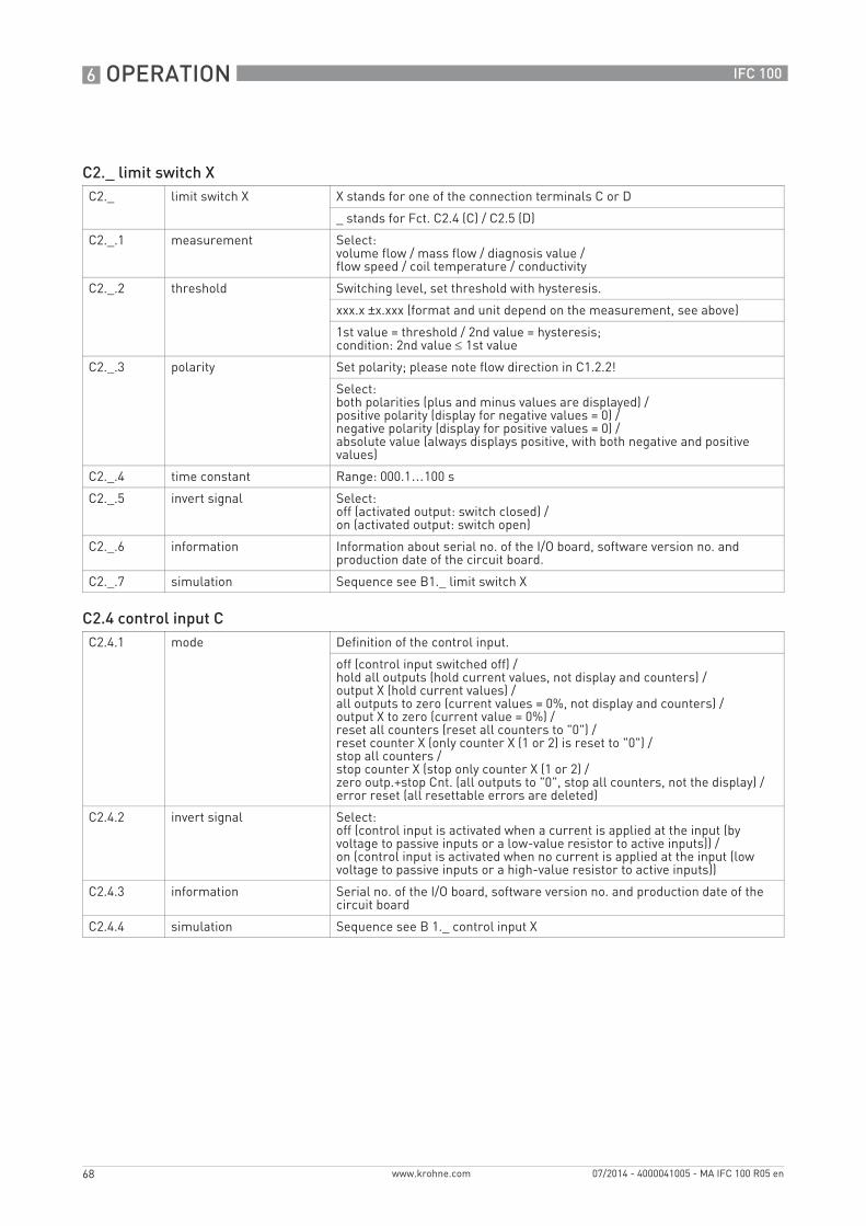
6 OPERATION
68
IFC 100
www.krohne.com 07/2014 - 4000041005 - MA IFC 100 R05 en
C2._ limit switch XC2._ limit switch X X stands for one of the connection terminals C or D
_ stands for Fct. C2.4 (C) / C2.5 (D)
C2._.1 measurement Select:volume flow / mass flow / diagnosis value /flow speed / coil temperature / conductivity
C2._.2 threshold Switching level, set threshold with hysteresis.
xxx.x ±x.xxx (format and unit depend on the measurement, see above)
1st value = threshold / 2nd value = hysteresis;condition: 2nd value ≤ 1st value
C2._.3 polarity Set polarity; please note flow direction in C1.2.2!
Select:both polarities (plus and minus values are displayed) /positive polarity (display for negative values = 0) /negative polarity (display for positive values = 0) /absolute value (always displays positive, with both negative and positive values)
C2._.4 time constant Range: 000.1…100 s
C2._.5 invert signal Select: off (activated output: switch closed) /on (activated output: switch open)
C2._.6 information Information about serial no. of the I/O board, software version no. and production date of the circuit board.
C2._.7 simulation Sequence see B1._ limit switch X
C2.4 control input CC2.4.1 mode Definition of the control input.
off (control input switched off) /hold all outputs (hold current values, not display and counters) /output X (hold current values) /all outputs to zero (current values = 0%, not display and counters) /output X to zero (current value = 0%) /reset all counters (reset all counters to "0") /reset counter X (only counter X (1 or 2) is reset to "0") /stop all counters /stop counter X (stop only counter X (1 or 2) /zero outp.+stop Cnt. (all outputs to "0", stop all counters, not the display) /error reset (all resettable errors are deleted)
C2.4.2 invert signal Select:off (control input is activated when a current is applied at the input (by voltage to passive inputs or a low-value resistor to active inputs)) /on (control input is activated when no current is applied at the input (low voltage to passive inputs or a high-value resistor to active inputs))
C2.4.3 information Serial no. of the I/O board, software version no. and production date of the circuit board
C2.4.4 simulation Sequence see B 1._ control input X
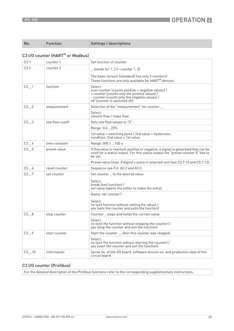
OPERATION 6
69
IFC 100
www.krohne.com07/2014 - 4000041005 - MA IFC 100 R05 en
No. Function Settings / descriptions
C3 I/O counter (HART® or Modbus)C3.1 counter 1 Set function of counter.
_ stands for 1, 2 (= counter 1, 2)
The basic version (standard) has only 2 counters!These functions are only available for HART® devices.
C3.2 counter 2
C3._.1 function Select:sum counter (counts positive + negative values) /+ counter (counts only the positive values) /- counter (counts only the negative values) /off (counter is switched off)
C3._.2 measurement Selection of the "measurement" for counter _.
Select:volume flow / mass flow
C3._.3 low flow cutoff Sets low flow values to "0".
Range: 0.0…20%
1st value = switching point / 2nd value = hysteresis;condition: 2nd value ≤ 1st value
C3._.4 time constant Range: 000.1…100 s
C3._.5 preset value If this value is reached, positive or negative, a signal is generated that can be used for a status output. For this status output the "preset counter X" has to be set.
Preset value (max. 8 digits) x.xxxxx in selected unit (see C5.7.10 and C5.7.13).
C3._.6 reset counter Sequence see Fct. A3.2 and A3.3.
C3._.7 set counter Set counter _ to the desired value.
Select:break (exit function) /set value (opens the editor to make the entry)
Query: set counter?
Select:no (exit function without setting the value) /yes (sets the counter and exits the function)
C3._.8 stop counter Counter _ stops and holds the current value.
Select:no (exit the function without stopping the counter) /yes (stop the counter and exit the function)
C3._.9 start counter Start the counter _, after this counter was stopped.
Select:no (exit the function without starting the counter) /yes (start the counter and exit the function)
C3._.10 information Serial no. of the I/O board, software version no. and production date of the circuit board
C3 I/O counter (Profibus)For the detailed description of the Profibus functions refer to the corresponding supplementary instructions.
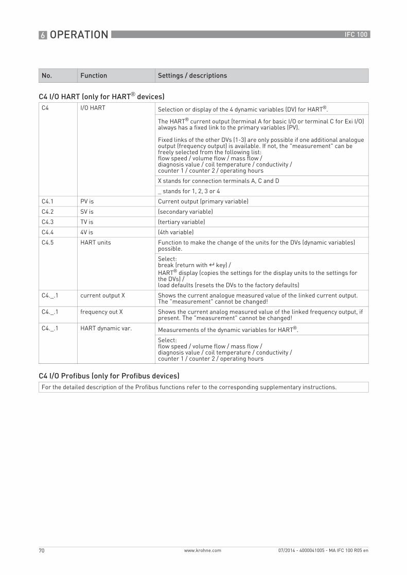
6 OPERATION
70
IFC 100
www.krohne.com 07/2014 - 4000041005 - MA IFC 100 R05 en
No. Function Settings / descriptions
C4 I/O HART (only for HART® devices)C4 I/O HART Selection or display of the 4 dynamic variables (DV) for HART®.
The HART® current output (terminal A for basic I/O or terminal C for Exi I/O) always has a fixed link to the primary variables (PV).
Fixed links of the other DVs (1-3) are only possible if one additional analogue output (frequency output) is available. If not, the "measurement" can be freely selected from the following list:flow speed / volume flow / mass flow /diagnosis value / coil temperature / conductivity /counter 1 / counter 2 / operating hours
X stands for connection terminals A, C and D
_ stands for 1, 2, 3 or 4
C4.1 PV is Current output (primary variable)
C4.2 SV is (secondary variable)
C4.3 TV is (tertiary variable)
C4.4 4V is (4th variable)
C4.5 HART units Function to make the change of the units for the DVs (dynamic variables) possible.
Select:break (return with ^ key) /HART® display (copies the settings for the display units to the settings for the DVs) /load defaults (resets the DVs to the factory defaults)
C4._.1 current output X Shows the current analogue measured value of the linked current output. The "measurement" cannot be changed!
C4._.1 frequency out X Shows the current analog measured value of the linked frequency output, if present. The "measurement" cannot be changed!
C4._.1 HART dynamic var. Measurements of the dynamic variables for HART®.
Select:flow speed / volume flow / mass flow /diagnosis value / coil temperature / conductivity /counter 1 / counter 2 / operating hours
C4 I/O Profibus (only for Profibus devices)For the detailed description of the Profibus functions refer to the corresponding supplementary instructions.
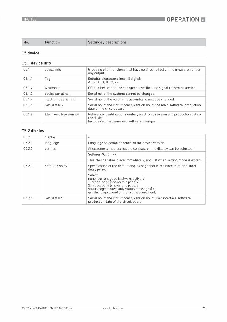
OPERATION 6
71
IFC 100
www.krohne.com07/2014 - 4000041005 - MA IFC 100 R05 en
No. Function Settings / descriptions
C5 device
C5.1 device infoC5.1 device info Grouping of all functions that have no direct effect on the measurement or
any output.
C5.1.1 Tag Settable characters (max. 8 digits): A…Z; a…z; 0…9; / - , .
C5.1.2 C number CG number, cannot be changed; describes the signal converter version
C5.1.3 device serial no. Serial no. of the system; cannot be changed.
C5.1.4 electronic serial no. Serial no. of the electronic assembly; cannot be changed.
C5.1.5 SW.REV.MS Serial no. of the circuit board, version no. of the main software, production date of the circuit board
C5.1.6 Electronic Revision ER Reference identification number, electronic revision and production date of the deviceIncludes all hardware and software changes.
C5.2 displayC5.2 display -
C5.2.1 language Language selection depends on the device version.
C5.2.2 contrast At extreme temperatures the contrast on the display can be adjusted.
Setting: -9…0…+9
This change takes place immediately, not just when setting mode is exited!
C5.2.3 default display Specification of the default display page that is returned to after a short delay period.
Select:none (current page is always active) /1. meas. page (shows this page) /2. meas. page (shows this page) /status page (shows only status messages) /graphic page (trend of the 1st measurement)
C5.2.5 SW.REV.UIS Serial no. of the circuit board, version no. of user interface software, production date of the circuit board
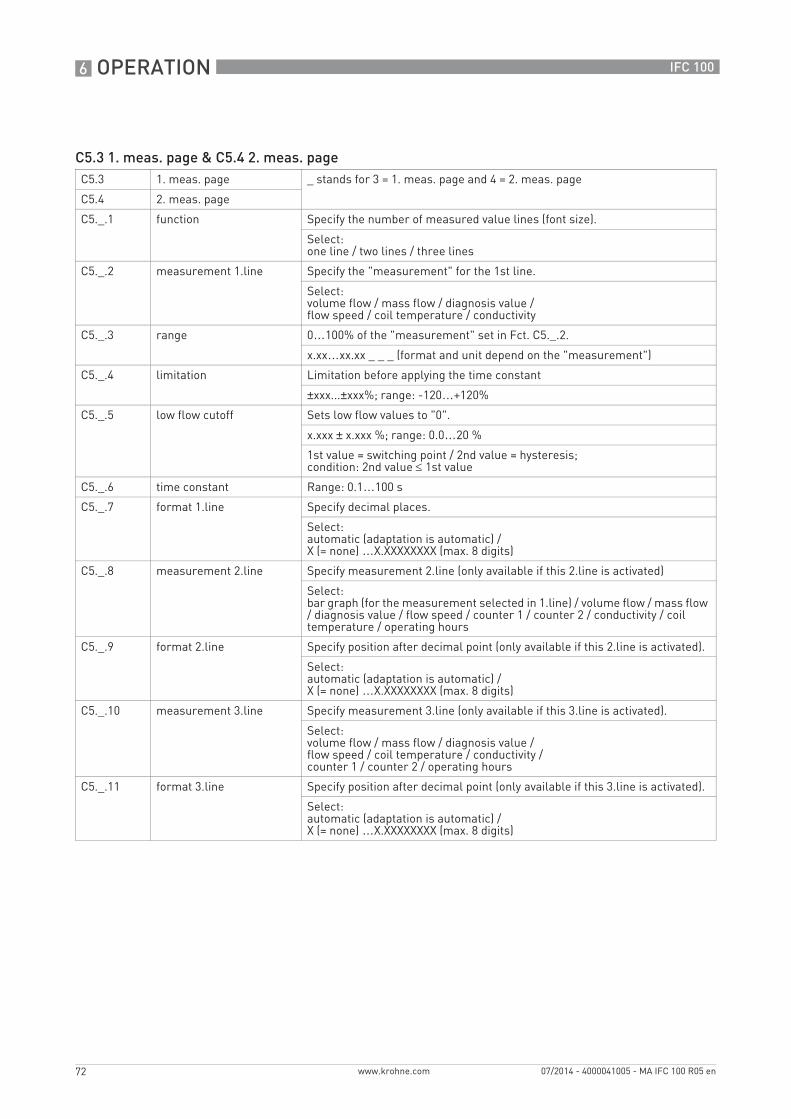
6 OPERATION
72
IFC 100
www.krohne.com 07/2014 - 4000041005 - MA IFC 100 R05 en
C5.3 1. meas. page & C5.4 2. meas. pageC5.3 1. meas. page _ stands for 3 = 1. meas. page and 4 = 2. meas. page
C5.4 2. meas. page
C5._.1 function Specify the number of measured value lines (font size).
Select:one line / two lines / three lines
C5._.2 measurement 1.line Specify the "measurement" for the 1st line.
Select:volume flow / mass flow / diagnosis value /flow speed / coil temperature / conductivity
C5._.3 range 0…100% of the "measurement" set in Fct. C5._.2.
x.xx…xx.xx _ _ _ (format and unit depend on the "measurement")
C5._.4 limitation Limitation before applying the time constant
±xxx...±xxx%; range: -120…+120%
C5._.5 low flow cutoff Sets low flow values to "0".
x.xxx ± x.xxx %; range: 0.0…20 %
1st value = switching point / 2nd value = hysteresis;condition: 2nd value ≤ 1st value
C5._.6 time constant Range: 0.1…100 s
C5._.7 format 1.line Specify decimal places.
Select:automatic (adaptation is automatic) /X (= none) …X.XXXXXXXX (max. 8 digits)
C5._.8 measurement 2.line Specify measurement 2.line (only available if this 2.line is activated)
Select:bar graph (for the measurement selected in 1.line) / volume flow / mass flow / diagnosis value / flow speed / counter 1 / counter 2 / conductivity / coil temperature / operating hours
C5._.9 format 2.line Specify position after decimal point (only available if this 2.line is activated).
Select:automatic (adaptation is automatic) /X (= none) …X.XXXXXXXX (max. 8 digits)
C5._.10 measurement 3.line Specify measurement 3.line (only available if this 3.line is activated).
Select:volume flow / mass flow / diagnosis value /flow speed / coil temperature / conductivity /counter 1 / counter 2 / operating hours
C5._.11 format 3.line Specify position after decimal point (only available if this 3.line is activated).
Select:automatic (adaptation is automatic) /X (= none) …X.XXXXXXXX (max. 8 digits)
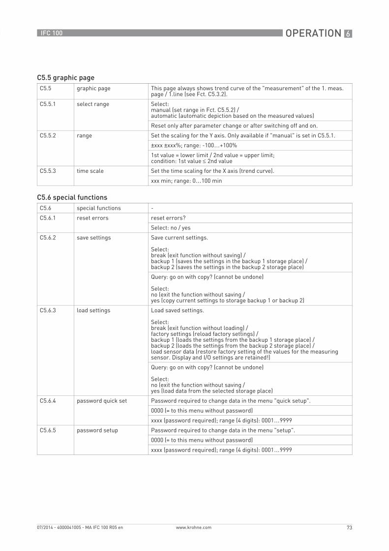
OPERATION 6
73
IFC 100
www.krohne.com07/2014 - 4000041005 - MA IFC 100 R05 en
C5.5 graphic pageC5.5 graphic page This page always shows trend curve of the "measurement" of the 1. meas.
page / 1.line (see Fct. C5.3.2).
C5.5.1 select range Select:manual (set range in Fct. C5.5.2) /automatic (automatic depiction based on the measured values)
Reset only after parameter change or after switching off and on.
C5.5.2 range Set the scaling for the Y axis. Only available if "manual" is set in C5.5.1.
±xxx ±xxx%; range: -100…+100%
1st value = lower limit / 2nd value = upper limit;condition: 1st value ≤ 2nd value
C5.5.3 time scale Set the time scaling for the X axis (trend curve).
xxx min; range: 0…100 min
C5.6 special functionsC5.6 special functions -
C5.6.1 reset errors reset errors?
Select: no / yes
C5.6.2 save settings Save current settings.
Select:break (exit function without saving) /backup 1 (saves the settings in the backup 1 storage place) /backup 2 (saves the settings in the backup 2 storage place)
Query: go on with copy? (cannot be undone)
Select:no (exit the function without saving /yes (copy current settings to storage backup 1 or backup 2)
C5.6.3 load settings Load saved settings.
Select:break (exit function without loading) /factory settings (reload factory settings) /backup 1 (loads the settings from the backup 1 storage place) /backup 2 (loads the settings from the backup 2 storage place) /load sensor data (restore factory setting of the values for the measuring sensor. Display and I/O settings are retained!)
Query: go on with copy? (cannot be undone)
Select:no (exit the function without saving /yes (load data from the selected storage place)
C5.6.4 password quick set Password required to change data in the menu "quick setup".
0000 (= to this menu without password)
xxxx (password required); range (4 digits): 0001…9999
C5.6.5 password setup Password required to change data in the menu "setup".
0000 (= to this menu without password)
xxxx (password required); range (4 digits): 0001…9999
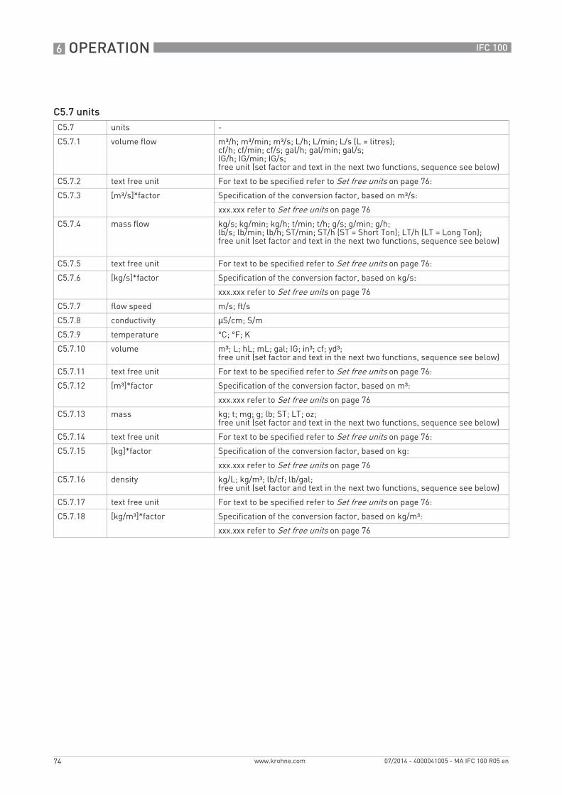
6 OPERATION
74
IFC 100
www.krohne.com 07/2014 - 4000041005 - MA IFC 100 R05 en
C5.7 unitsC5.7 units -
C5.7.1 volume flow m³/h; m³/min; m³/s; L/h; L/min; L/s (L = litres); cf/h; cf/min; cf/s; gal/h; gal/min; gal/s;IG/h; IG/min; IG/s;free unit (set factor and text in the next two functions, sequence see below)
C5.7.2 text free unit For text to be specified refer to Set free units on page 76:
C5.7.3 [m³/s]*factor Specification of the conversion factor, based on m³/s:
xxx.xxx refer to Set free units on page 76
C5.7.4 mass flow kg/s; kg/min; kg/h; t/min; t/h; g/s; g/min; g/h; lb/s; lb/min; lb/h; ST/min; ST/h (ST = Short Ton); LT/h (LT = Long Ton);free unit (set factor and text in the next two functions, sequence see below)
C5.7.5 text free unit For text to be specified refer to Set free units on page 76:
C5.7.6 [kg/s]*factor Specification of the conversion factor, based on kg/s:
xxx.xxx refer to Set free units on page 76
C5.7.7 flow speed m/s; ft/s
C5.7.8 conductivity µS/cm; S/m
C5.7.9 temperature °C; °F; K
C5.7.10 volume m³; L; hL; mL; gal; IG; in³; cf; yd³;free unit (set factor and text in the next two functions, sequence see below)
C5.7.11 text free unit For text to be specified refer to Set free units on page 76:
C5.7.12 [m³]*factor Specification of the conversion factor, based on m³:
xxx.xxx refer to Set free units on page 76
C5.7.13 mass kg; t; mg; g; lb; ST; LT; oz;free unit (set factor and text in the next two functions, sequence see below)
C5.7.14 text free unit For text to be specified refer to Set free units on page 76:
C5.7.15 [kg]*factor Specification of the conversion factor, based on kg:
xxx.xxx refer to Set free units on page 76
C5.7.16 density kg/L; kg/m³; lb/cf; lb/gal;free unit (set factor and text in the next two functions, sequence see below)
C5.7.17 text free unit For text to be specified refer to Set free units on page 76:
C5.7.18 [kg/m³]*factor Specification of the conversion factor, based on kg/m³:
xxx.xxx refer to Set free units on page 76
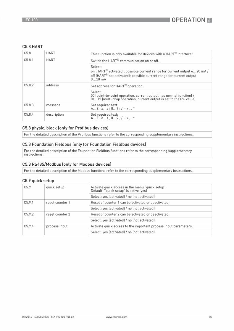
OPERATION 6
75
IFC 100
www.krohne.com07/2014 - 4000041005 - MA IFC 100 R05 en
C5.8 HARTC5.8 HART This function is only available for devices with a HART® interface!
C5.8.1 HART Switch the HART® communication on or off.
Select:on (HART® activated); possible current range for current output 4…20 mA /off (HART® not activated); possible current range for current output 0…20 mA
C5.8.2 address Set address for HART® operation.
Select:00 (point-to-point operation, current output has normal function) /01...15 (multi-drop operation, current output is set to the 0% value)
C5.8.3 message Set required text:A…Z ; a…z ; 0…9 ; / - + , . *
C5.8.4 description Set required text:A…Z ; a…z ; 0…9 ; / - + , . *
C5.8 physic. block (only for Profibus devices)For the detailed description of the Profibus functions refer to the corresponding supplementary instructions.
C5.8 Foundation Fieldbus (only for Foundation Fieldbus devices)For the detailed description of the Foundation Fieldbus functions refer to the corresponding supplementary instructions.
C5.8 RS485/Modbus (only for Modbus devices)For the detailed description of the Modbus functions refer to the corresponding supplementary instructions.
C5.9 quick setupC5.9 quick setup Activate quick access in the menu "quick setup".
Default: "quick setup" is active (yes)
Select: yes (activated) / no (not activated)
C5.9.1 reset counter 1 Reset of counter 1 can be activated or deactivated.
Select: yes (activated) / no (not activated)
C5.9.2 reset counter 2 Reset of counter 2 can be activated or deactivated.
Select: yes (activated) / no (not activated)
C5.9.4 process input Activate quick access to the important process input parameters.
Select: yes (activated) / no (not activated)
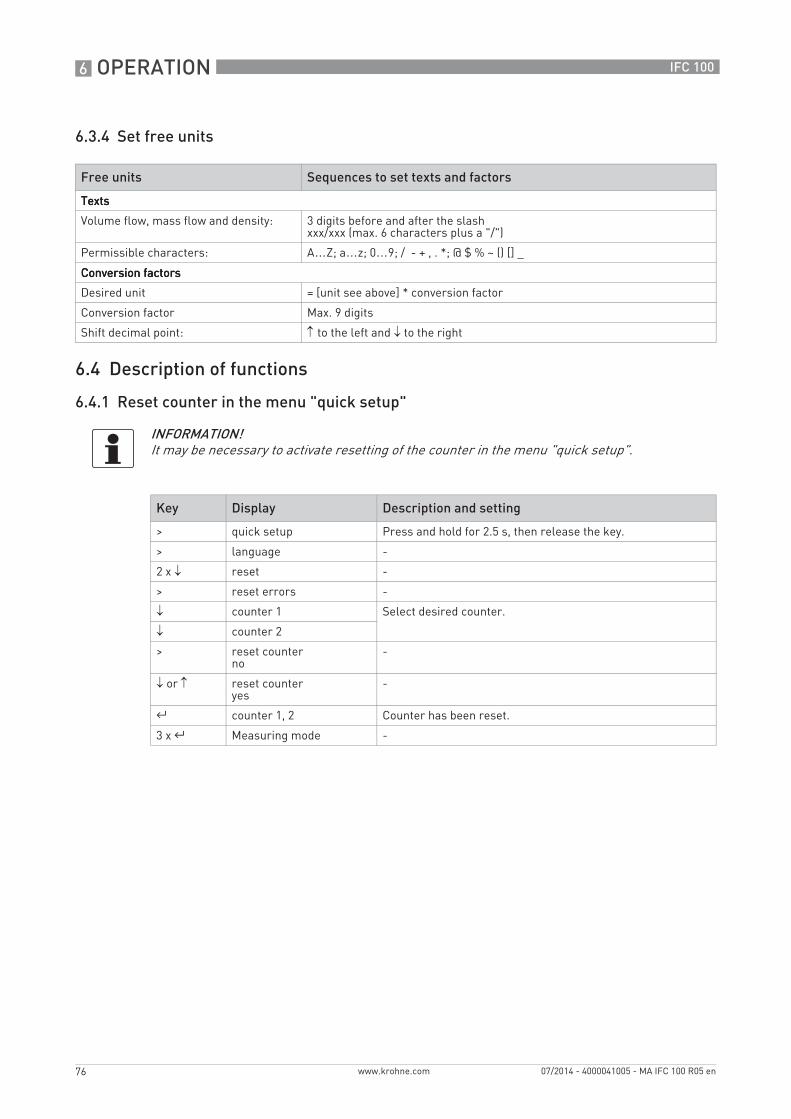
6 OPERATION
76
IFC 100
www.krohne.com 07/2014 - 4000041005 - MA IFC 100 R05 en
6.3.4 Set free units
6.4 Description of functions
6.4.1 Reset counter in the menu "quick setup"
Free units Sequences to set texts and factors
TextsTextsTextsTexts
Volume flow, mass flow and density: 3 digits before and after the slashxxx/xxx (max. 6 characters plus a "/")
Permissible characters: A…Z; a…z; 0…9; / - + , . *; @ $ % ~ () [] _
Conversion factorsConversion factorsConversion factorsConversion factors
Desired unit = [unit see above] * conversion factor
Conversion factor Max. 9 digits
Shift decimal point: ↑ to the left and ↓ to the right
INFORMATION!It may be necessary to activate resetting of the counter in the menu "quick setup".
Key Display Description and setting
> quick setup Press and hold for 2.5 s, then release the key.
> language -
2 x ↓ reset -
> reset errors -
↓ counter 1 Select desired counter.
↓ counter 2
> reset counterno
-
↓ or ↑ reset counteryes
-
^ counter 1, 2 Counter has been reset.
3 x ^ Measuring mode -

OPERATION 6
77
IFC 100
www.krohne.com07/2014 - 4000041005 - MA IFC 100 R05 en
6.4.2 Deleting error messages in the menu "quick setup"
6.5 Status messages and diagnostic information
Each status message (= status signal) has a specific symbol, determined by NAMUR, which is displayed with the message. The length of each message is limited to one line.
INFORMATION!For the detailed list of the possible error messages refer to Status messages and diagnostic information on page 77.
Key Display Description and setting
> quick setup Press and hold for 2.5 s, then release the key.
> language -
2 x ↓ reset -
> reset errors -
> reset?no
-
↓ or ↑ reset?yes
-
^ reset errors Error has been reset.
3 x ^ Measuring mode -
INFORMATION! As status message always the name of the relevant status group and the status signal is displayed.
Symbol Symbol background colour
Letter Status signal Description and consequence
white FFFF(bold)
Error in device No measurement possible.
blue F Application error No measurement possible due to process/application conditions.The device is still OK.
blue S Out of specification Measurements are available but are no longer sufficiently accurate and should be checked.
blue C Checks in progress A test function is active. The displayed or transferred measured value does not correspond to the actual measured value.
- - I Information No direct influence on the measurements.
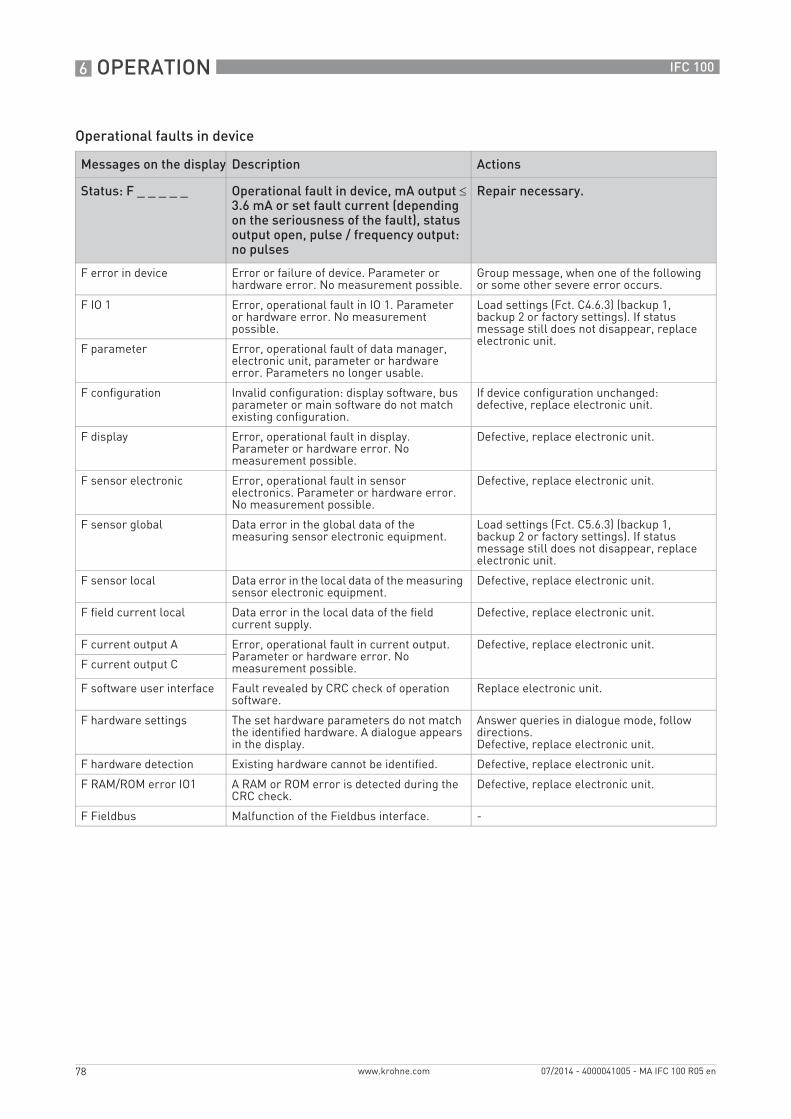
6 OPERATION
78
IFC 100
www.krohne.com 07/2014 - 4000041005 - MA IFC 100 R05 en
Operational faults in device
Messages on the display Description Actions
Status: F _ _ _ _ _ Operational fault in device, mA output ≤ 3.6 mA or set fault current (depending on the seriousness of the fault), status output open, pulse / frequency output: no pulses
Repair necessary.
F error in device Error or failure of device. Parameter or hardware error. No measurement possible.
Group message, when one of the following or some other severe error occurs.
F IO 1 Error, operational fault in IO 1. Parameter or hardware error. No measurement possible.
Load settings (Fct. C4.6.3) (backup 1, backup 2 or factory settings). If status message still does not disappear, replace electronic unit.
F parameter Error, operational fault of data manager, electronic unit, parameter or hardware error. Parameters no longer usable.
F configuration Invalid configuration: display software, bus parameter or main software do not match existing configuration.
If device configuration unchanged: defective, replace electronic unit.
F display Error, operational fault in display. Parameter or hardware error. No measurement possible.
Defective, replace electronic unit.
F sensor electronic Error, operational fault in sensor electronics. Parameter or hardware error. No measurement possible.
Defective, replace electronic unit.
F sensor global Data error in the global data of the measuring sensor electronic equipment.
Load settings (Fct. C5.6.3) (backup 1, backup 2 or factory settings). If status message still does not disappear, replace electronic unit.
F sensor local Data error in the local data of the measuring sensor electronic equipment.
Defective, replace electronic unit.
F field current local Data error in the local data of the field current supply.
Defective, replace electronic unit.
F current output A Error, operational fault in current output. Parameter or hardware error. No measurement possible.
Defective, replace electronic unit.
F current output C
F software user interface Fault revealed by CRC check of operation software.
Replace electronic unit.
F hardware settings The set hardware parameters do not match the identified hardware. A dialogue appears in the display.
Answer queries in dialogue mode, follow directions.Defective, replace electronic unit.
F hardware detection Existing hardware cannot be identified. Defective, replace electronic unit.
F RAM/ROM error IO1 A RAM or ROM error is detected during the CRC check.
Defective, replace electronic unit.
F Fieldbus Malfunction of the Fieldbus interface. -

OPERATION 6
79
IFC 100
www.krohne.com07/2014 - 4000041005 - MA IFC 100 R05 en
Application error
Measurements out of specification
Messages on the display Description Actions
Status: F _ _ _ _ _ Application-dependent fault, device OK, but measured values affected.
Application test or operator action necessary.
F application error Application-dependent fault, but device is okay.
Group message, when errors as described below or other application errors occur.
F empty pipe 1 or 2 measuring electrodes are not in contact with the medium; measured value is set to zero. No measurement possible.
Measuring pipe not filled, function dependent on C1.3.2. Check installation. Or electrodes completely insulated e.g. by oil film. Clean!
F flow exceeding limit Measuring range exceeded, filter setting limits measured values. No message if empty pipe.
Limitation Fct. C1.2.1, increase values.
If this limit occurs sporadically in processes with air pockets, solid contents or low conductivity, then either the limit has to be increased or a pulse filter used so as to quell the error messages and also reduce the measurement errors.
F field frequency too high Field frequency is not reaching steady state, a measured flow value is still being supplied but may have errors. Measured values are still supplied, but they are always too low. No message if coil broken or bridged.
If Fct. C1.1.14 settling time is on "manual", increase the value in Fct. C1.1.15. If it is set to "standard", set the field frequency in Fct. C1.1.13 according to the signal converter nameplate.
F DC offset ADC over-ranged by DC offsets. No measurement can be performed, the flow is set to zero. No message if empty pipe.
For remote signal converters, check the connection of the signal cable.
F open circuit A Load on current output A too high, effective current too low.
Current not correct, mA output cable has open circuit or load too high. Check cable, reduce load (set < 750 ohm).F open circuit C
F over range A The current or the corresponding measured value is limited by a filter setting.
Check with Fct. C2.1 hardware or sticker in terminal compartment, which output is connected to the terminal.If current output: extend Fct. C2.x.6 range and Fct. C2.x.8 limitation.If frequency output: extend values in Fct. C2.x.5 and Fct. C2.x.7.
F over range C
F over range D The pulse rate or the corresponding measured value is limited by a filter setting. Or the demanded pulse rate is too high.
F active settings Error during the CRC check of the active settings.
Upload backup 1 or backup 2 settings, check and adjust if necessary.
F factory settings Error during the CRC check of the factory settings.
-
F backup 1 settings Error during the CRC check of the backup 1 or 2 settings.
Save active settings in backup 1 or 2.
F backup 2 settings
Messages on the display Description Actions
Status: S _ _ _ _ _ Out of specification, measurement continues, accuracy possibly less.
Maintenance required.
S uncertain measurement Device maintenance necessary; measured values only conditionally usable.
Group message, when errors as described below or other influences occur.
S empty pipe 1 or 2 measuring electrodes are not in contact with the medium; measured value is set to zero. No measurement possible.
Measuring pipe not filled, function dependent on C1.3.2. Check installation. Or electrodes completely insulated e.g. by oil film. Clean!
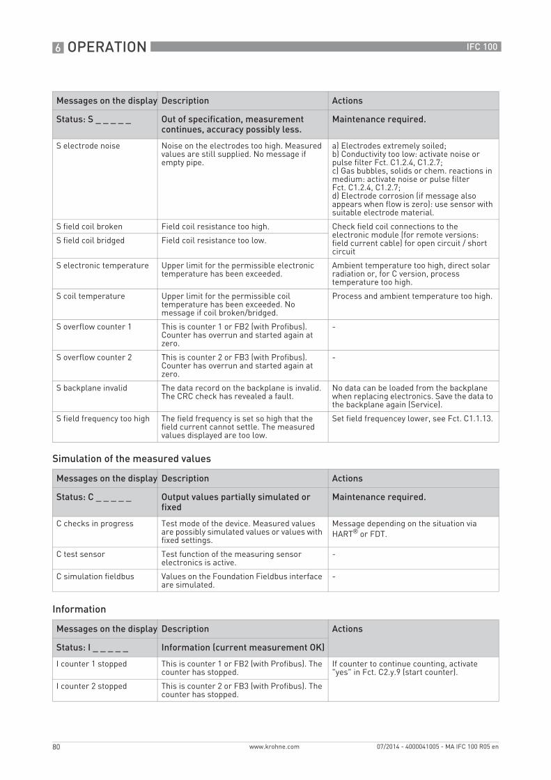
6 OPERATION
80
IFC 100
www.krohne.com 07/2014 - 4000041005 - MA IFC 100 R05 en
Simulation of the measured values
Information
S electrode noise Noise on the electrodes too high. Measured values are still supplied. No message if empty pipe.
a) Electrodes extremely soiled;b) Conductivity too low: activate noise or pulse filter Fct. C1.2.4, C1.2.7;c) Gas bubbles, solids or chem. reactions in medium: activate noise or pulse filter Fct. C1.2.4, C1.2.7;d) Electrode corrosion (if message also appears when flow is zero): use sensor with suitable electrode material.
S field coil broken Field coil resistance too high. Check field coil connections to the electronic module (for remote versions: field current cable) for open circuit / short circuit
S field coil bridged Field coil resistance too low.
S electronic temperature Upper limit for the permissible electronic temperature has been exceeded.
Ambient temperature too high, direct solar radiation or, for C version, process temperature too high.
S coil temperature Upper limit for the permissible coil temperature has been exceeded. No message if coil broken/bridged.
Process and ambient temperature too high.
S overflow counter 1 This is counter 1 or FB2 (with Profibus). Counter has overrun and started again at zero.
-
S overflow counter 2 This is counter 2 or FB3 (with Profibus). Counter has overrun and started again at zero.
-
S backplane invalid The data record on the backplane is invalid. The CRC check has revealed a fault.
No data can be loaded from the backplane when replacing electronics. Save the data to the backplane again (Service).
S field frequency too high The field frequency is set so high that the field current cannot settle. The measured values displayed are too low.
Set field frequencey lower, see Fct. C1.1.13.
Messages on the display Description Actions
Status: C _ _ _ _ _ Output values partially simulated or fixed
Maintenance required.
C checks in progress Test mode of the device. Measured values are possibly simulated values or values with fixed settings.
Message depending on the situation via HART® or FDT.
C test sensor Test function of the measuring sensor electronics is active.
-
C simulation fieldbus Values on the Foundation Fieldbus interface are simulated.
-
Messages on the display Description Actions
Status: I _ _ _ _ _ Information (current measurement OK)
I counter 1 stopped This is counter 1 or FB2 (with Profibus). The counter has stopped.
If counter to continue counting, activate "yes" in Fct. C2.y.9 (start counter).
I counter 2 stopped This is counter 2 or FB3 (with Profibus). The counter has stopped.
Messages on the display Description Actions
Status: S _ _ _ _ _ Out of specification, measurement continues, accuracy possibly less.
Maintenance required.
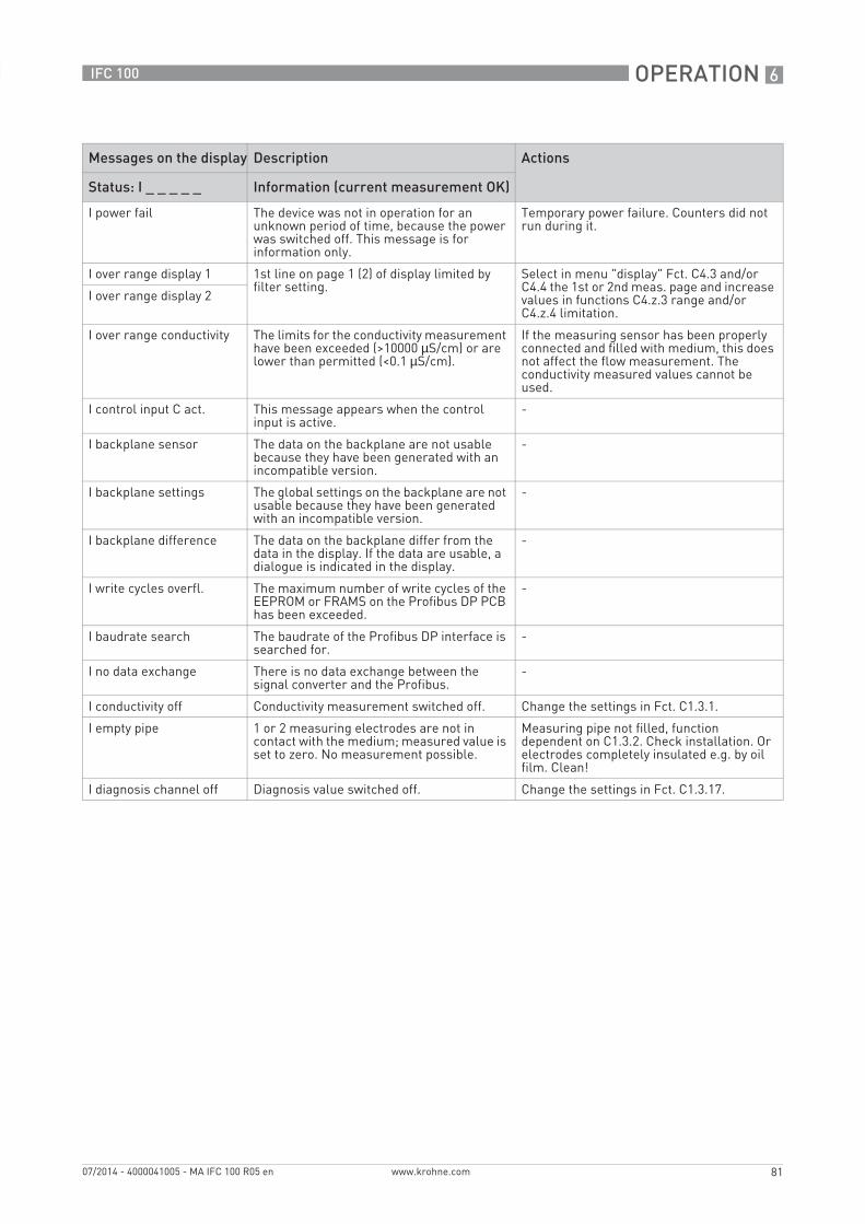
OPERATION 6
81
IFC 100
www.krohne.com07/2014 - 4000041005 - MA IFC 100 R05 en
I power fail The device was not in operation for an unknown period of time, because the power was switched off. This message is for information only.
Temporary power failure. Counters did not run during it.
I over range display 1 1st line on page 1 (2) of display limited by filter setting.
Select in menu "display" Fct. C4.3 and/or C4.4 the 1st or 2nd meas. page and increase values in functions C4.z.3 range and/or C4.z.4 limitation.
I over range display 2
I over range conductivity The limits for the conductivity measurement have been exceeded (>10000 µS/cm) or are lower than permitted (<0.1 µS/cm).
If the measuring sensor has been properly connected and filled with medium, this does not affect the flow measurement. The conductivity measured values cannot be used.
I control input C act. This message appears when the control input is active.
-
I backplane sensor The data on the backplane are not usable because they have been generated with an incompatible version.
-
I backplane settings The global settings on the backplane are not usable because they have been generated with an incompatible version.
-
I backplane difference The data on the backplane differ from the data in the display. If the data are usable, a dialogue is indicated in the display.
-
I write cycles overfl. The maximum number of write cycles of the EEPROM or FRAMS on the Profibus DP PCB has been exceeded.
-
I baudrate search The baudrate of the Profibus DP interface is searched for.
-
I no data exchange There is no data exchange between the signal converter and the Profibus.
-
I conductivity off Conductivity measurement switched off. Change the settings in Fct. C1.3.1.
I empty pipe 1 or 2 measuring electrodes are not in contact with the medium; measured value is set to zero. No measurement possible.
Measuring pipe not filled, function dependent on C1.3.2. Check installation. Or electrodes completely insulated e.g. by oil film. Clean!
I diagnosis channel off Diagnosis value switched off. Change the settings in Fct. C1.3.17.
Messages on the display Description Actions
Status: I _ _ _ _ _ Information (current measurement OK)

7 SERVICE
82
IFC 100
www.krohne.com 07/2014 - 4000041005 - MA IFC 100 R05 en
7.1 Spare parts availability
The manufacturer adheres to the basic principle that functionally adequate spare parts for each device or each important accessory part will be kept available for a period of 3 years after delivery of the last production run for the device.
This regulation only applies to spare parts which are subject to wear and tear under normal operating conditions.
7.2 Availability of services
The manufacturer offers a range of services to support the customer after expiration of the warranty. These include repair, maintenance, technical support and training.
7.3 Returning the device to the manufacturer
7.3.1 General information
This device has been carefully manufactured and tested. If installed and operated in accordance with these operating instructions, it will rarely present any problems.
INFORMATION!For more precise information, please contact your local sales office.
CAUTION!Should you nevertheless need to return a device for inspection or repair, please pay strict attention to the following points:• Due to statutory regulations on environmental protection and safeguarding the health and
safety of our personnel, manufacturer may only handle, test and repair returned devices that have been in contact with products without risk to personnel and environment.
• This means that the manufacturer can only service this device if it is accompanied by the following certificate (see next section) confirming that the device is safe to handle.
CAUTION!If the device has been operated with toxic, caustic, flammable or water-endangering products, you are kindly requested:• to check and ensure, if necessary by rinsing or neutralising, that all cavities are free from
such dangerous substances,• to enclose a certificate with the device confirming that is safe to handle and stating the
product used.
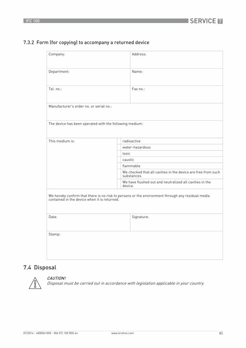
SERVICE 7
83
IFC 100
www.krohne.com07/2014 - 4000041005 - MA IFC 100 R05 en
7.3.2 Form (for copying) to accompany a returned device
7.4 Disposal
Company: Address:
Department: Name:
Tel. no.: Fax no.:
Manufacturer's order no. or serial no.:
The device has been operated with the following medium:
This medium is: radioactive
water-hazardous
toxic
caustic
flammable
We checked that all cavities in the device are free from such substances.
We have flushed out and neutralized all cavities in the device.
We hereby confirm that there is no risk to persons or the environment through any residual media contained in the device when it is returned.
Date: Signature:
Stamp:
CAUTION!Disposal must be carried out in accordance with legislation applicable in your country.

8 TECHNICAL DATA
84
IFC 100
www.krohne.com 07/2014 - 4000041005 - MA IFC 100 R05 en
8.1 Measuring principle
An electrically conductive fluid flows inside an electrically insulated pipe through a magnetic field. This magnetic field is generated by a current, flowing through a pair of field coils.Inside of the fluid, a voltage U is generated:
U = v * k * B * DU = v * k * B * DU = v * k * B * DU = v * k * B * D
in which:v = mean flow velocityk = factor correcting for geometryB = magnetic field strengthD = inner diameter of flow meter
The signal voltage U is picked off by electrodes and is proportional to the mean flow velocity v and thus the flow rate q. A signal converter is used to amplify the signal voltage, filter it and convert it into signals for totalising, recording and output processing.
Figure 8-1: Measuring principle
1 Induced voltage (proportional to flow velocity)2 Electrodes3 Magnetic field4 Field coils
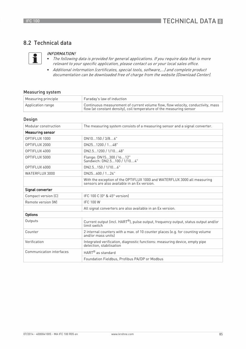
TECHNICAL DATA 8
85
IFC 100
www.krohne.com07/2014 - 4000041005 - MA IFC 100 R05 en
8.2 Technical data
INFORMATION!• The following data is provided for general applications. If you require data that is more
relevant to your specific application, please contact us or your local sales office.• Additional information (certificates, special tools, software,...) and complete product
documentation can be downloaded free of charge from the website (Download Center).
Measuring systemMeasuring principle Faraday's law of induction
Application range Continuous measurement of current volume flow, flow velocity, conductivity, mass flow (at constant density), coil temperature of the measuring sensor
DesignModular construction The measuring system consists of a measuring sensor and a signal converter.
Measuring sensorMeasuring sensorMeasuring sensorMeasuring sensor
OPTIFLUX 1000 DN10...150 / 3/8…6"
OPTIFLUX 2000 DN25...1200 / 1…48"
OPTIFLUX 4000 DN2.5...1200 / 1/10…48"
OPTIFLUX 5000 Flange: DN15...300 / ½…12"Sandwich: DN2.5...100 / 1/10…4"
OPTIFLUX 6000 DN2.5...150 / 1/10…6"
WATERFLUX 3000 DN25...600 / 1...24"
With the exception of the OPTIFLUX 1000 and WATERFLUX 3000 all measuring sensors are also available in an Ex version.
Signal converterSignal converterSignal converterSignal converter
Compact version (C) IFC 100 C (0° & 45° version)
Remote version (W) IFC 100 W
All signal converters are also available in an Ex version.
OptionsOptionsOptionsOptions
Outputs Current output (incl. HART®), pulse output, frequency output, status output and/or limit switch
Counter 2 internal counters with a max. of 10 counter places (e.g. for counting volume and/or mass units)
Verification Integrated verification, diagnostic functions: measuring device, empty pipe detection, stabilisation
Communication interfaces HART® as standard
Foundation Fieldbus, Profibus PA/DP or Modbus
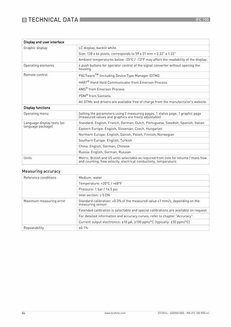
8 TECHNICAL DATA
86
IFC 100
www.krohne.com 07/2014 - 4000041005 - MA IFC 100 R05 en
Display and user interfaceDisplay and user interfaceDisplay and user interfaceDisplay and user interface
Graphic display LC display, backlit white.
Size: 128 x 64 pixels, corresponds to 59 x 31 mm = 2.32" x 1.22"
Ambient temperatures below -25°C / -13°F may affect the readability of the display.
Operating elements 4 push buttons for operator control of the signal converter without opening the housing.
Remote control PACTwareTM (including Device Type Manager (DTM))
HART® Hand Held Communicator from Emerson Process
AMS® from Emerson Process
PDM® from Siemens
All DTMs and drivers are available free of charge from the manufacturer's website.
Display functionsDisplay functionsDisplay functionsDisplay functions
Operating menu Setting the parameters using 2 measuring pages, 1 status page, 1 graphic page (measured values and graphics are freely adjustable)
Language display texts (as language package)
Standard: English, French, German, Dutch, Portuguese, Swedish, Spanish, Italian
Eastern Europe: English, Slovenian, Czech, Hungarian
Northern Europe: English, Danish, Polish, Finnish, Norwegian
Southern Europe: English, Turkish
China: English, German, Chinese
Russia: English, German, Russian
Units Metric, British and US units selectable as required from lists for volume / mass flow and counting, flow velocity, electrical conductivity, temperature
Measuring accuracyReference conditions Medium: water
Temperature: +20°C / +68°F
Pressure: 1 bar / 14.5 psi
Inlet section: ≥ 5 DN
Maximum measuring error Standard calibration: +0.3% of the measured value +1 mm/s, depending on the measuring sensor
Extended calibration is selectable and special calibrations are available on request.
For detailed information and accuracy curves, refer to chapter "Accuracy".
Current output electronics: ±10 µA; ±100 ppm/°C (typically: ±30 ppm/°C)
Repeatability ±0.1%
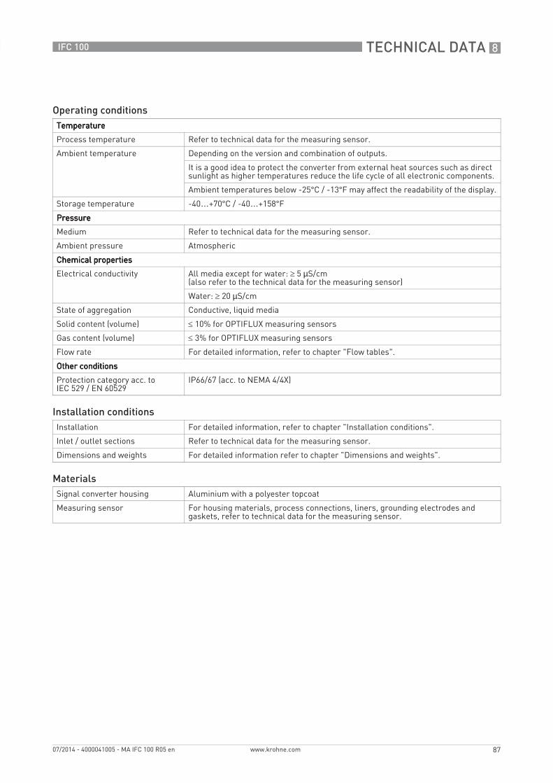
TECHNICAL DATA 8
87
IFC 100
www.krohne.com07/2014 - 4000041005 - MA IFC 100 R05 en
Operating conditionsTemperatureTemperatureTemperatureTemperature
Process temperature Refer to technical data for the measuring sensor.
Ambient temperature Depending on the version and combination of outputs.
It is a good idea to protect the converter from external heat sources such as direct sunlight as higher temperatures reduce the life cycle of all electronic components.
Ambient temperatures below -25°C / -13°F may affect the readability of the display.
Storage temperature -40…+70°C / -40…+158°F
PressurePressurePressurePressure
Medium Refer to technical data for the measuring sensor.
Ambient pressure Atmospheric
Chemical propertiesChemical propertiesChemical propertiesChemical properties
Electrical conductivity All media except for water: ≥ 5 µS/cm(also refer to the technical data for the measuring sensor)
Water: ≥ 20 µS/cm
State of aggregation Conductive, liquid media
Solid content (volume) ≤ 10% for OPTIFLUX measuring sensors
Gas content (volume) ≤ 3% for OPTIFLUX measuring sensors
Flow rate For detailed information, refer to chapter "Flow tables".
Other conditionsOther conditionsOther conditionsOther conditions
Protection category acc. to IEC 529 / EN 60529
IP66/67 (acc. to NEMA 4/4X)
Installation conditionsInstallation For detailed information, refer to chapter "Installation conditions".
Inlet / outlet sections Refer to technical data for the measuring sensor.
Dimensions and weights For detailed information refer to chapter "Dimensions and weights".
MaterialsSignal converter housing Aluminium with a polyester topcoat
Measuring sensor For housing materials, process connections, liners, grounding electrodes and gaskets, refer to technical data for the measuring sensor.
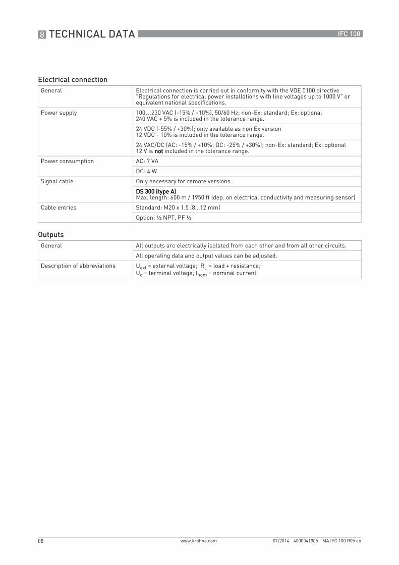
8 TECHNICAL DATA
88
IFC 100
www.krohne.com 07/2014 - 4000041005 - MA IFC 100 R05 en
Electrical connectionGeneral Electrical connection is carried out in conformity with the VDE 0100 directive
"Regulations for electrical power installations with line voltages up to 1000 V" or equivalent national specifications.
Power supply 100…230 VAC (-15% / +10%), 50/60 Hz; non-Ex: standard; Ex: optional240 VAC + 5% is included in the tolerance range.
24 VDC (-55% / +30%); only available as non Ex version12 VDC - 10% is included in the tolerance range.
24 VAC/DC (AC: -15% / +10%; DC: -25% / +30%); non-Ex: standard; Ex: optional12 V is notnotnotnot included in the tolerance range.
Power consumption AC: 7 VA
DC: 4 W
Signal cable Only necessary for remote versions.
DS 300 (type A)DS 300 (type A)DS 300 (type A)DS 300 (type A)Max. length: 600 m / 1950 ft (dep. on electrical conductivity and measuring sensor)
Cable entries Standard: M20 x 1.5 (8...12 mm)
Option: ½ NPT, PF ½
OutputsGeneral All outputs are electrically isolated from each other and from all other circuits.
All operating data and output values can be adjusted.
Description of abbreviations Uext = external voltage; RL = load + resistance; Uo = terminal voltage; Inom = nominal current
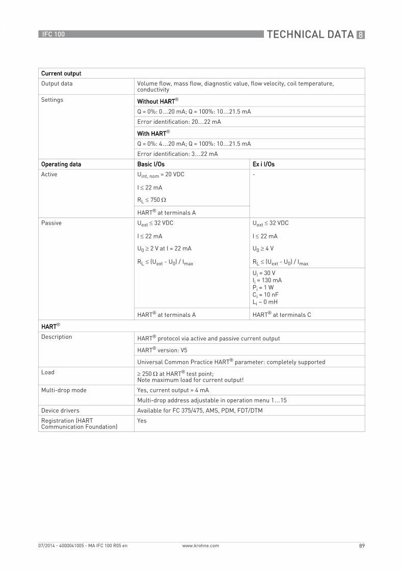
TECHNICAL DATA 8
89
IFC 100
www.krohne.com07/2014 - 4000041005 - MA IFC 100 R05 en
Current outputCurrent outputCurrent outputCurrent output
Output data Volume flow, mass flow, diagnostic value, flow velocity, coil temperature, conductivity
Settings Without HARTWithout HARTWithout HARTWithout HART®
Q = 0%: 0…20 mA; Q = 100%: 10…21.5 mA
Error identification: 20…22 mA
With HARTWith HARTWith HARTWith HART®
Q = 0%: 4…20 mA; Q = 100%: 10…21.5 mA
Error identification: 3…22 mA
Operating dataOperating dataOperating dataOperating data Basic I/OsBasic I/OsBasic I/OsBasic I/Os Ex i I/OsEx i I/OsEx i I/OsEx i I/Os
Active Uint, nom = 20 VDC
I ≤ 22 mA
RL ≤ 750 Ω
-
HART® at terminals A
Passive Uext ≤ 32 VDC
I ≤ 22 mA
U0 ≥ 2 V at I = 22 mA
RL ≤ (Uext - U0) / Imax
Uext ≤ 32 VDC
I ≤ 22 mA
U0 ≥ 4 V
RL ≤ (Uext - U0) / Imax
Ui = 30 VIi = 130 mAPi = 1 WCi = 10 nFLi ~ 0 mH
HART® at terminals A HART® at terminals C
HARTHARTHARTHART®
Description HART® protocol via active and passive current output
HART® version: V5
Universal Common Practice HART® parameter: completely supported
Load ≥ 250 Ω at HART® test point;Note maximum load for current output!
Multi-drop mode Yes, current output = 4 mA
Multi-drop address adjustable in operation menu 1…15
Device drivers Available for FC 375/475, AMS, PDM, FDT/DTM
Registration (HART Communication Foundation)
Yes
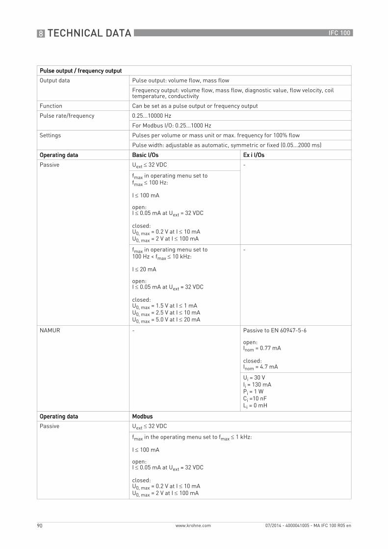
8 TECHNICAL DATA
90
IFC 100
www.krohne.com 07/2014 - 4000041005 - MA IFC 100 R05 en
Pulse output / frequency outputPulse output / frequency outputPulse output / frequency outputPulse output / frequency output
Output data Pulse output: volume flow, mass flow
Frequency output: volume flow, mass flow, diagnostic value, flow velocity, coil temperature, conductivity
Function Can be set as a pulse output or frequency output
Pulse rate/frequency 0.25...10000 Hz
For Modbus I/O: 0.25...1000 Hz
Settings Pulses per volume or mass unit or max. frequency for 100% flow
Pulse width: adjustable as automatic, symmetric or fixed (0.05...2000 ms)
Operating dataOperating dataOperating dataOperating data Basic I/OsBasic I/OsBasic I/OsBasic I/Os Ex i I/OsEx i I/OsEx i I/OsEx i I/Os
Passive Uext ≤ 32 VDC -
fmax in operating menu set to fmax ≤ 100 Hz:
I ≤ 100 mA
open:I ≤ 0.05 mA at Uext = 32 VDC
closed:U0, max = 0.2 V at I ≤ 10 mAU0, max = 2 V at I ≤ 100 mA
fmax in operating menu set to100 Hz < fmax ≤ 10 kHz:
I ≤ 20 mA
open:I ≤ 0.05 mA at Uext = 32 VDC
closed:U0, max = 1.5 V at I ≤ 1 mAU0, max = 2.5 V at I ≤ 10 mAU0, max = 5.0 V at I ≤ 20 mA
-
NAMUR - Passive to EN 60947-5-6
open:Inom = 0.77 mA
closed:Inom = 4.7 mA
Ui = 30 VIi = 130 mAPi = 1 WCi =10 nFLi = 0 mH
Operating dataOperating dataOperating dataOperating data ModbusModbusModbusModbus
Passive Uext ≤ 32 VDC
fmax in the operating menu set to fmax ≤ 1 kHz:
I ≤ 100 mA
open:I ≤ 0.05 mA at Uext = 32 VDC
closed:U0, max = 0.2 V at I ≤ 10 mAU0, max = 2 V at I ≤ 100 mA
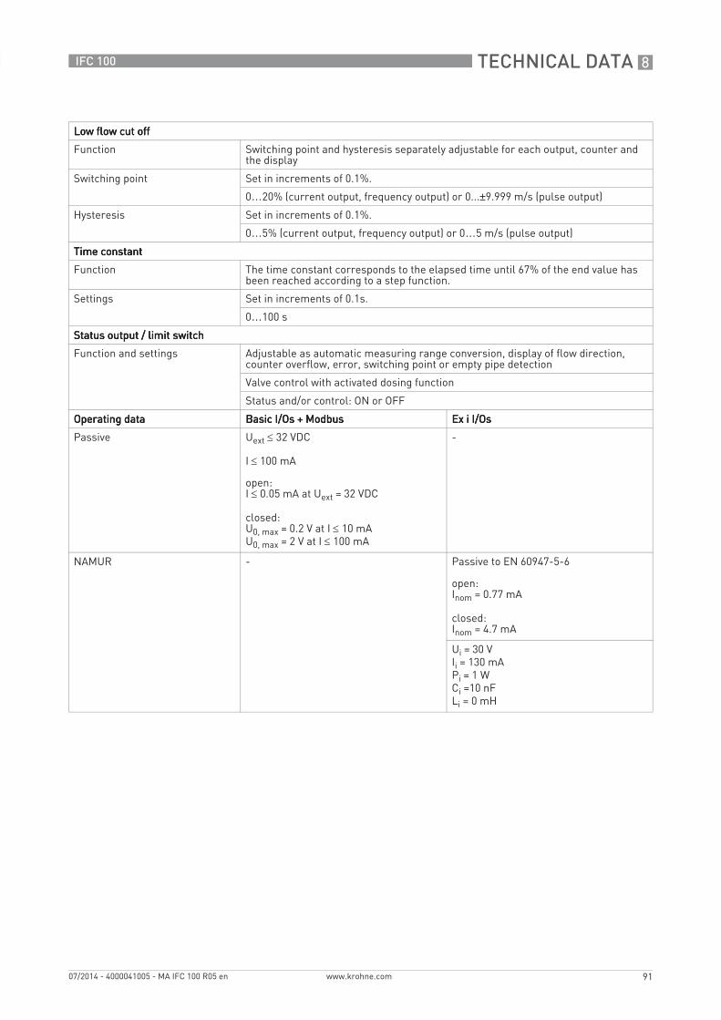
TECHNICAL DATA 8
91
IFC 100
www.krohne.com07/2014 - 4000041005 - MA IFC 100 R05 en
Low flow cut offLow flow cut offLow flow cut offLow flow cut off
Function Switching point and hysteresis separately adjustable for each output, counter and the display
Switching point Set in increments of 0.1%.
0…20% (current output, frequency output) or 0...±9.999 m/s (pulse output)
Hysteresis Set in increments of 0.1%.
0…5% (current output, frequency output) or 0…5 m/s (pulse output)
Time constantTime constantTime constantTime constant
Function The time constant corresponds to the elapsed time until 67% of the end value has been reached according to a step function.
Settings Set in increments of 0.1s.
0…100 s
Status output / limit switchStatus output / limit switchStatus output / limit switchStatus output / limit switch
Function and settings Adjustable as automatic measuring range conversion, display of flow direction, counter overflow, error, switching point or empty pipe detection
Valve control with activated dosing function
Status and/or control: ON or OFF
Operating dataOperating dataOperating dataOperating data Basic I/Os + ModbusBasic I/Os + ModbusBasic I/Os + ModbusBasic I/Os + Modbus Ex i I/OsEx i I/OsEx i I/OsEx i I/Os
Passive Uext ≤ 32 VDC
I ≤ 100 mA
open:I ≤ 0.05 mA at Uext = 32 VDC
closed:U0, max = 0.2 V at I ≤ 10 mAU0, max = 2 V at I ≤ 100 mA
-
NAMUR - Passive to EN 60947-5-6
open:Inom = 0.77 mA
closed:Inom = 4.7 mA
Ui = 30 VIi = 130 mAPi = 1 WCi =10 nFLi = 0 mH
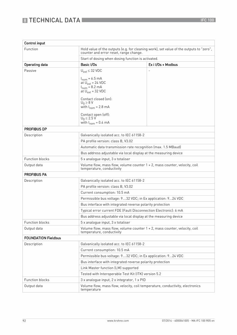
8 TECHNICAL DATA
92
IFC 100
www.krohne.com 07/2014 - 4000041005 - MA IFC 100 R05 en
Control inputControl inputControl inputControl input
Function Hold value of the outputs (e.g. for cleaning work), set value of the outputs to "zero", counter and error reset, range change.
Start of dosing when dosing function is activated.
Operating dataOperating dataOperating dataOperating data Basic I/OsBasic I/OsBasic I/OsBasic I/Os Ex i I/Os + ModbusEx i I/Os + ModbusEx i I/Os + ModbusEx i I/Os + Modbus
Passive Uext ≤ 32 VDC
Inom = 6.5 mAat Uext = 24 VDCInom = 8.2 mAat Uext = 32 VDC
Contact closed (on):U0 ≥ 8 Vwith Inom = 2.8 mA
Contact open (off):U0 ≤ 2.5 Vwith Inom = 0.4 mA
-
PROFIBUS DPPROFIBUS DPPROFIBUS DPPROFIBUS DP
Description Galvanically isolated acc. to IEC 61158-2
PA profile version: class B, V3.02
Automatic data transmission rate recognition (max. 1.5 MBaud)
Bus address adjustable via local display at the measuring device
Function blocks 5 x analogue input, 3 x totaliser
Output data Volume flow, mass flow, volume counter 1 + 2, mass counter, velocity, coil temperature, conductivity
PROFIBUS PAPROFIBUS PAPROFIBUS PAPROFIBUS PA
Description Galvanically isolated acc. to IEC 61158-2
PA profile version: class B, V3.02
Current consumption: 10.5 mA
Permissible bus voltage: 9…32 VDC; in Ex application: 9...24 VDC
Bus interface with integrated reverse polarity protection
Typical error current FDE (Fault Disconnection Electronic): 6 mA
Bus address adjustable via local display at the measuring device
Function blocks 5 x analogue input, 3 x totaliser
Output data Volume flow, mass flow, volume counter 1 + 2, mass counter, velocity, coil temperature, conductivity
FOUNDATION FieldbusFOUNDATION FieldbusFOUNDATION FieldbusFOUNDATION Fieldbus
Description Galvanically isolated acc. to IEC 61158-2
Current consumption: 10.5 mA
Permissible bus voltage: 9…32 VDC; in Ex application: 9...24 VDC
Bus interface with integrated reverse polarity protection
Link Master function (LM) supported
Tested with Interoperable Test Kit (ITK) version 5.2
Function blocks 3 x analogue input, 2 x integrator, 1 x PID
Output data Volume flow, mass flow, velocity, coil temperature, conductivity, electronics temperature
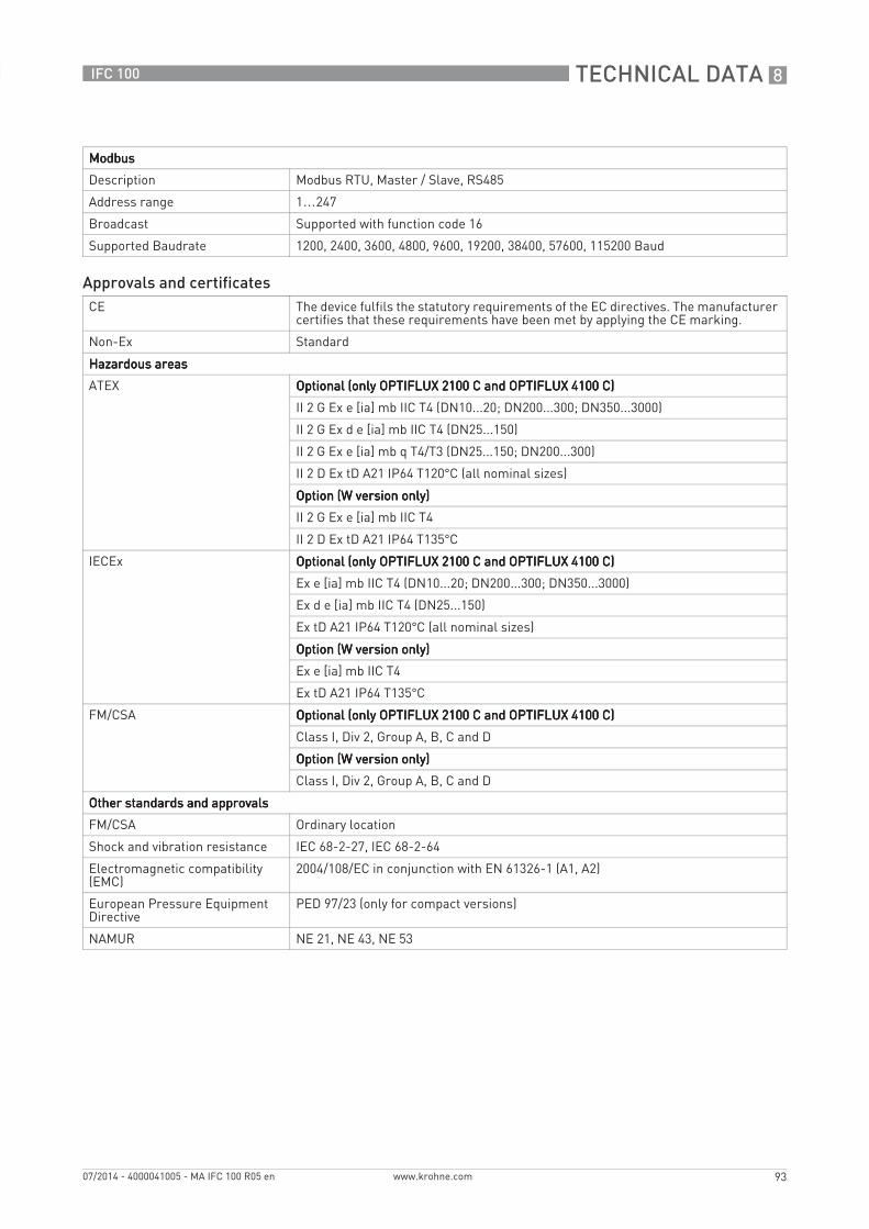
TECHNICAL DATA 8
93
IFC 100
www.krohne.com07/2014 - 4000041005 - MA IFC 100 R05 en
ModbusModbusModbusModbus
Description Modbus RTU, Master / Slave, RS485
Address range 1…247
Broadcast Supported with function code 16
Supported Baudrate 1200, 2400, 3600, 4800, 9600, 19200, 38400, 57600, 115200 Baud
Approvals and certificatesCE The device fulfils the statutory requirements of the EC directives. The manufacturer
certifies that these requirements have been met by applying the CE marking.
Non-Ex Standard
Hazardous areasHazardous areasHazardous areasHazardous areas
ATEX Optional (only OPTIFLUX 2100 C and OPTIFLUX 4100 C)Optional (only OPTIFLUX 2100 C and OPTIFLUX 4100 C)Optional (only OPTIFLUX 2100 C and OPTIFLUX 4100 C)Optional (only OPTIFLUX 2100 C and OPTIFLUX 4100 C)
II 2 G Ex e [ia] mb IIC T4 (DN10...20; DN200...300; DN350...3000)
II 2 G Ex d e [ia] mb IIC T4 (DN25...150)
II 2 G Ex e [ia] mb q T4/T3 (DN25...150; DN200...300)
II 2 D Ex tD A21 IP64 T120°C (all nominal sizes)
Option (W version only)Option (W version only)Option (W version only)Option (W version only)
II 2 G Ex e [ia] mb IIC T4
II 2 D Ex tD A21 IP64 T135°C
IECEx Optional (only OPTIFLUX 2100 C and OPTIFLUX 4100 C)Optional (only OPTIFLUX 2100 C and OPTIFLUX 4100 C)Optional (only OPTIFLUX 2100 C and OPTIFLUX 4100 C)Optional (only OPTIFLUX 2100 C and OPTIFLUX 4100 C)
Ex e [ia] mb IIC T4 (DN10...20; DN200...300; DN350...3000)
Ex d e [ia] mb IIC T4 (DN25...150)
Ex tD A21 IP64 T120°C (all nominal sizes)
Option (W version only)Option (W version only)Option (W version only)Option (W version only)
Ex e [ia] mb IIC T4
Ex tD A21 IP64 T135°C
FM/CSA Optional (only OPTIFLUX 2100 C and OPTIFLUX 4100 C)Optional (only OPTIFLUX 2100 C and OPTIFLUX 4100 C)Optional (only OPTIFLUX 2100 C and OPTIFLUX 4100 C)Optional (only OPTIFLUX 2100 C and OPTIFLUX 4100 C)
Class I, Div 2, Group A, B, C and D
Option (W version only)Option (W version only)Option (W version only)Option (W version only)
Class I, Div 2, Group A, B, C and D
Other standards and approvalsOther standards and approvalsOther standards and approvalsOther standards and approvals
FM/CSA Ordinary location
Shock and vibration resistance IEC 68-2-27, IEC 68-2-64
Electromagnetic compatibility (EMC)
2004/108/EC in conjunction with EN 61326-1 (A1, A2)
European Pressure Equipment Directive
PED 97/23 (only for compact versions)
NAMUR NE 21, NE 43, NE 53
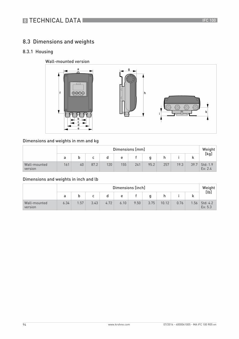
8 TECHNICAL DATA
94
IFC 100
www.krohne.com 07/2014 - 4000041005 - MA IFC 100 R05 en
8.3 Dimensions and weights
8.3.1 Housing
Dimensions and weights in mm and kg
Dimensions and weights in inch and lb
Wall-mounted version
Dimensions [mm] Weight [kg]
a b c d e f g h i k
Wall-mounted version
161 40 87.2 120 155 241 95.2 257 19.3 39.7 Std: 1.9Ex: 2.4
Dimensions [inch] Weight [lb]
a b c d e f g h i k
Wall-mounted version
6.34 1.57 3.43 4.72 6.10 9.50 3.75 10.12 0.76 1.56 Std: 4.2Ex: 5.3
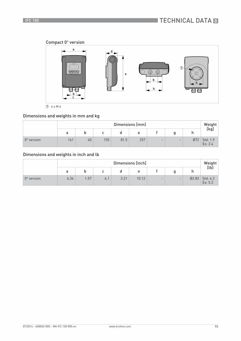
TECHNICAL DATA 8
95
IFC 100
www.krohne.com07/2014 - 4000041005 - MA IFC 100 R05 en
Dimensions and weights in mm and kg
Dimensions and weights in inch and lb
Compact 0° version
1 4 x M 6
Dimensions [mm] Weight [kg]
a b c d e f g h
0° version 161 40 155 81.5 257 - - Ø72 Std: 1.9Ex: 2.4
Dimensions [inch] Weight [lb]
a b c d e f g h
0° version 6.34 1.57 6.1 3.21 10.12 - - Ø2.83 Std: 4.2Ex: 5.3
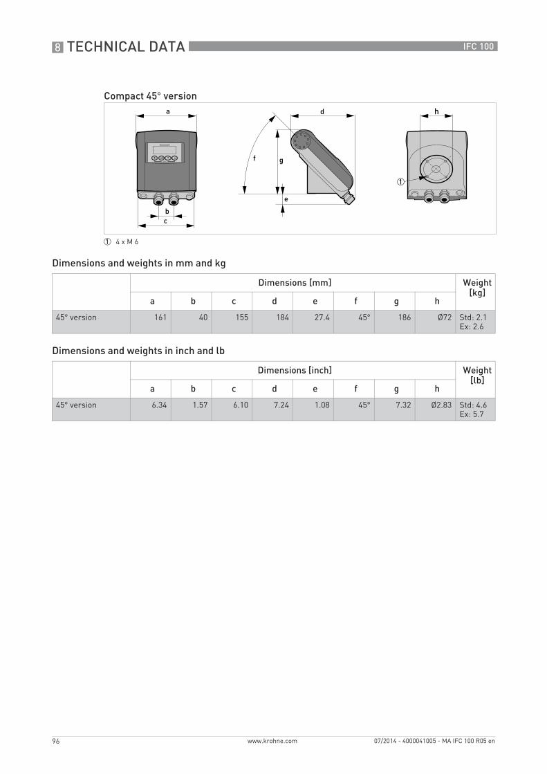
8 TECHNICAL DATA
96
IFC 100
www.krohne.com 07/2014 - 4000041005 - MA IFC 100 R05 en
Dimensions and weights in mm and kg
Dimensions and weights in inch and lb
Compact 45° version
1 4 x M 6
Dimensions [mm] Weight [kg]
a b c d e f g h
45° version 161 40 155 184 27.4 45° 186 Ø72 Std: 2.1Ex: 2.6
Dimensions [inch] Weight [lb]
a b c d e f g h
45° version 6.34 1.57 6.10 7.24 1.08 45° 7.32 Ø2.83 Std: 4.6Ex: 5.7
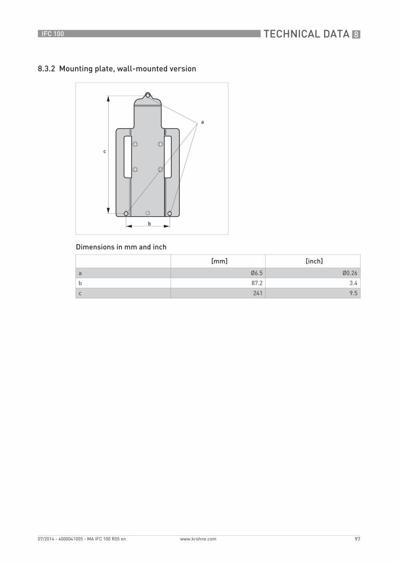
TECHNICAL DATA 8
97
IFC 100
www.krohne.com07/2014 - 4000041005 - MA IFC 100 R05 en
8.3.2 Mounting plate, wall-mounted version
Dimensions in mm and inch
[mm] [inch]
a Ø6.5 Ø0.26
b 87.2 3.4
c 241 9.5
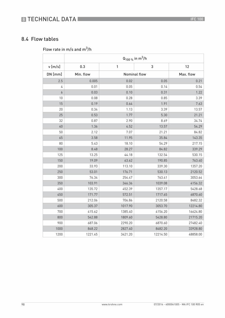
8 TECHNICAL DATA
98
IFC 100
www.krohne.com 07/2014 - 4000041005 - MA IFC 100 R05 en
8.4 Flow tables
Flow rate in m/s and m3/h
Q100 % in m3/h
v [m/s] 0.3 1 3 12
DN [mm] Min. flow Nominal flow Max. flow
2.5 0.005 0.02 0.05 0.21
4 0.01 0.05 0.14 0.54
6 0.03 0.10 0.31 1.22
10 0.08 0.28 0.85 3.39
15 0.19 0.64 1.91 7.63
20 0.34 1.13 3.39 13.57
25 0.53 1.77 5.30 21.21
32 0.87 2.90 8.69 34.74
40 1.36 4.52 13.57 54.29
50 2.12 7.07 21.21 84.82
65 3.58 11.95 35.84 143.35
80 5.43 18.10 54.29 217.15
100 8.48 28.27 84.82 339.29
125 13.25 44.18 132.54 530.15
150 19.09 63.62 190.85 763.40
200 33.93 113.10 339.30 1357.20
250 53.01 176.71 530.13 2120.52
300 76.34 254.47 763.41 3053.64
350 103.91 346.36 1039.08 4156.32
400 135.72 452.39 1357.17 5428.68
450 171.77 572.51 1717.65 6870.60
500 212.06 706.86 2120.58 8482.32
600 305.37 1017.90 3053.70 12214.80
700 415.62 1385.40 4156.20 16624.80
800 542.88 1809.60 5428.80 21715.20
900 687.06 2290.20 6870.60 27482.40
1000 848.22 2827.40 8482.20 33928.80
1200 1221.45 3421.20 12214.50 48858.00
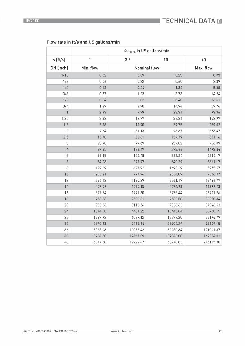
TECHNICAL DATA 8
99
IFC 100
www.krohne.com07/2014 - 4000041005 - MA IFC 100 R05 en
Flow rate in ft/s and US gallons/min
Q100 % in US gallons/min
v [ft/s] 1 3.3 10 40
DN [inch] Min. flow Nominal flow Max. flow
1/10 0.02 0.09 0.23 0.93
1/8 0.06 0.22 0.60 2.39
1/4 0.13 0.44 1.34 5.38
3/8 0.37 1.23 3.73 14.94
1/2 0.84 2.82 8.40 33.61
3/4 1.49 4.98 14.94 59.76
1 2.33 7.79 23.34 93.36
1.25 3.82 12.77 38.24 152.97
1.5 5.98 19.90 59.75 239.02
2 9.34 31.13 93.37 373.47
2.5 15.78 52.61 159.79 631.16
3 23.90 79.69 239.02 956.09
4 37.35 124.47 373.46 1493.84
5 58.35 194.48 583.24 2334.17
6 84.03 279.97 840.29 3361.17
8 149.39 497.92 1493.29 5975.57
10 233.41 777.96 2334.09 9336.37
12 336.12 1120.29 3361.19 13444.77
14 457.59 1525.15 4574.93 18299.73
16 597.54 1991.60 5975.44 23901.76
18 756.26 2520.61 7562.58 30250.34
20 933.86 3112.56 9336.63 37346.53
24 1344.50 4481.22 13445.04 53780.15
28 1829.92 6099.12 18299.20 73196.79
32 2390.23 7966.64 23902.29 95609.15
36 3025.03 10082.42 30250.34 121001.37
40 3734.50 12447.09 37346.00 149384.01
48 5377.88 17924.47 53778.83 215115.30

8 TECHNICAL DATA
100
IFC 100
www.krohne.com 07/2014 - 4000041005 - MA IFC 100 R05 en
8.5 Measuring accuracy
Reference conditions• Medium: water• Temperature: +20°C / +68°F• Pressure: 1 bar / 14.5 psi• Inlet section: ≥ 5 DN
X [m/s]: flow velocityY [%]: deviation from the actual measured value (mv)
Standard calibration DN [mm] DN [inch] Accuracy Curve
OPTIFLUX 2100 / 4100 / 5100 / 6100 10…1200 3/8…48 0.3% of mv + 1 mm/s 1
OPTIFLUX 1100 10…150 3/8…6 0.4% of mv + 1 mm/s as 1 + 0.1%
OPTIFLUX 4100 / 5100 / 6100 2.5…6 1/10…1/4
WATERFLUX 3100 25...600 1...24 0.3% of mv + 1 mm/s 1
Extended calibration DN [mm] DN [inch] Accuracy Curve
OPTIFLUX 2100 / 4100 / 5100 / 6100 10…1200 3/8…48 0.2% of mv + 1 mm/s as 1 - 0.1%
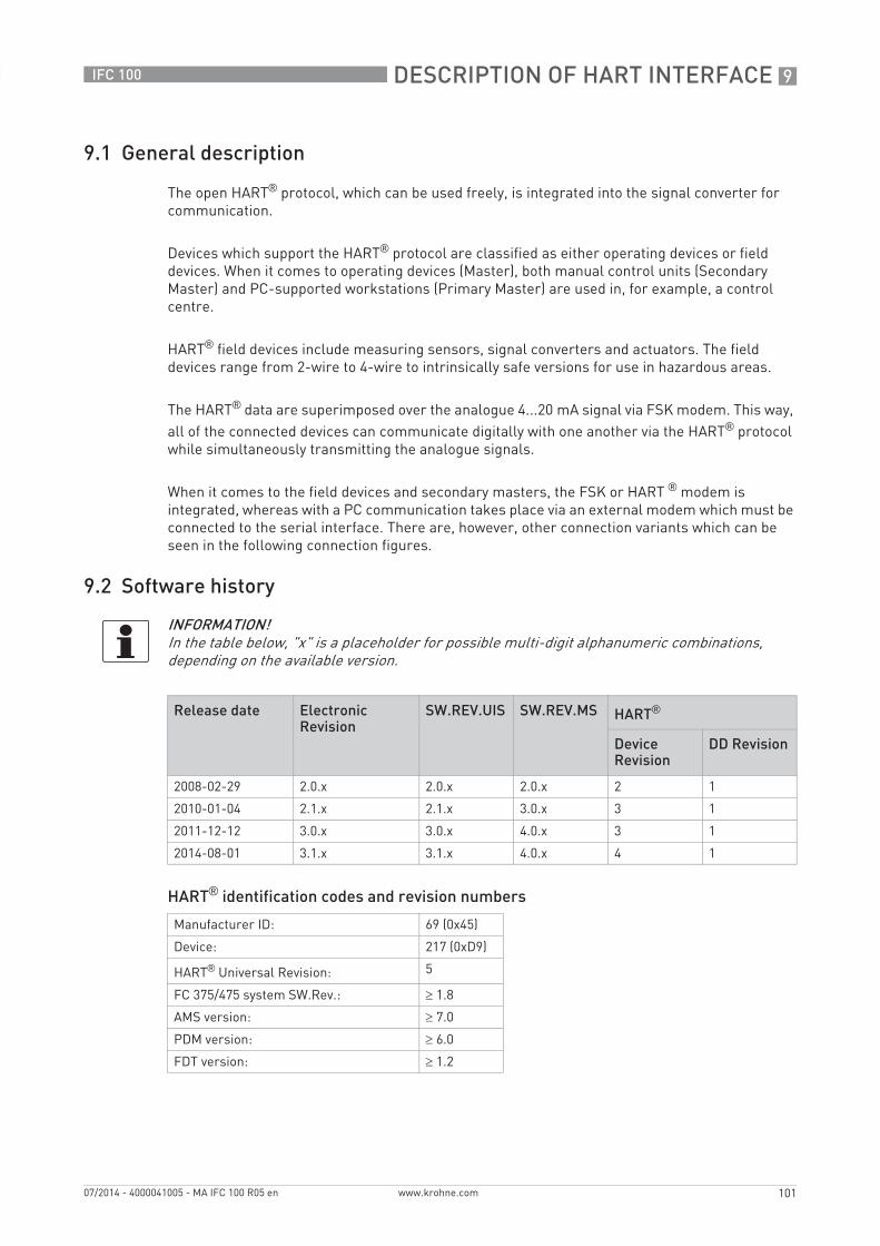
DESCRIPTION OF HART INTERFACE 9
101
IFC 100
www.krohne.com07/2014 - 4000041005 - MA IFC 100 R05 en
9.1 General description
The open HART® protocol, which can be used freely, is integrated into the signal converter for communication.
Devices which support the HART® protocol are classified as either operating devices or field devices. When it comes to operating devices (Master), both manual control units (Secondary Master) and PC-supported workstations (Primary Master) are used in, for example, a control centre.
HART® field devices include measuring sensors, signal converters and actuators. The field devices range from 2-wire to 4-wire to intrinsically safe versions for use in hazardous areas.
The HART® data are superimposed over the analogue 4...20 mA signal via FSK modem. This way, all of the connected devices can communicate digitally with one another via the HART® protocol while simultaneously transmitting the analogue signals.
When it comes to the field devices and secondary masters, the FSK or HART ® modem is integrated, whereas with a PC communication takes place via an external modem which must be connected to the serial interface. There are, however, other connection variants which can be seen in the following connection figures.
9.2 Software history
HART® identification codes and revision numbers
INFORMATION!In the table below, "x" is a placeholder for possible multi-digit alphanumeric combinations, depending on the available version.
Release date Electronic Revision
SW.REV.UIS SW.REV.MS HART®
Device Revision
DD Revision
2008-02-29 2.0.x 2.0.x 2.0.x 2 1
2010-01-04 2.1.x 2.1.x 3.0.x 3 1
2011-12-12 3.0.x 3.0.x 4.0.x 3 1
2014-08-01 3.1.x 3.1.x 4.0.x 4 1
Manufacturer ID: 69 (0x45)
Device: 217 (0xD9)
HART® Universal Revision: 5
FC 375/475 system SW.Rev.: ≥ 1.8
AMS version: ≥ 7.0
PDM version: ≥ 6.0
FDT version: ≥ 1.2

9 DESCRIPTION OF HART INTERFACE
102
IFC 100
www.krohne.com 07/2014 - 4000041005 - MA IFC 100 R05 en
9.3 Connection variants
The signal converter is a 4-wire device with 4...20 mA current output and HART® interface. Depending on the version, the settings and the wiring, the current output can operate as passive or active output.
• Multi-Drop Mode is supportedMulti-Drop Mode is supportedMulti-Drop Mode is supportedMulti-Drop Mode is supportedIn a Multi-Drop communication system, more than 2 devices are connected to a common transmission cable.
• Burst Mode is not supportedBurst Mode is not supportedBurst Mode is not supportedBurst Mode is not supportedIn the Burst Mode a slave device transfers cyclic pre-defined response telegrams, to get a higher rate of data transfer.
There are two ways of using the HART® communication:
• as Point-to-Point connection and• as multi-drop connection, with 2-wire connection or
as multi-drop connection, with 3-wire connection.
INFORMATION!For detailed information about the electrical connection of the signal converter for HART®, refer to the section "Electrical connection".
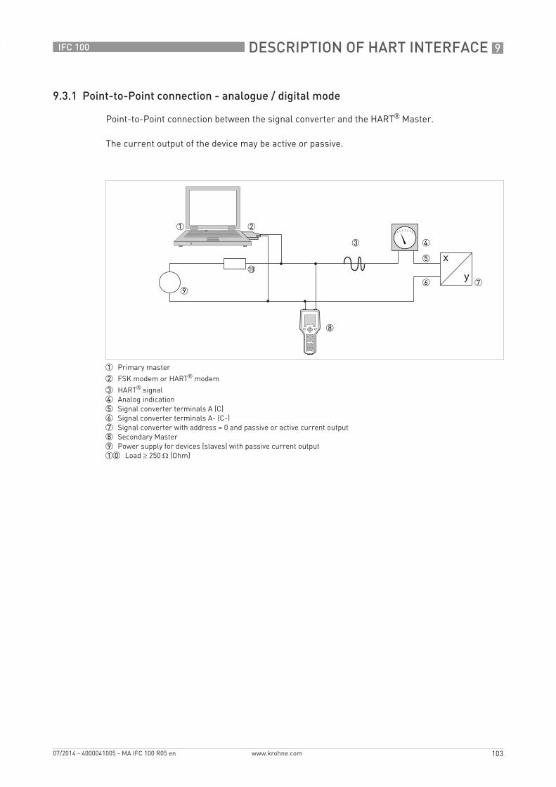
DESCRIPTION OF HART INTERFACE 9
103
IFC 100
www.krohne.com07/2014 - 4000041005 - MA IFC 100 R05 en
9.3.1 Point-to-Point connection - analogue / digital mode
Point-to-Point connection between the signal converter and the HART® Master.
The current output of the device may be active or passive.
1 Primary master
2 FSK modem or HART® modem
3 HART® signal4 Analog indication5 Signal converter terminals A (C)6 Signal converter terminals A- (C-)7 Signal converter with address = 0 and passive or active current output8 Secondary Master9 Power supply for devices (slaves) with passive current output10 Load ≥ 250 Ω (Ohm)
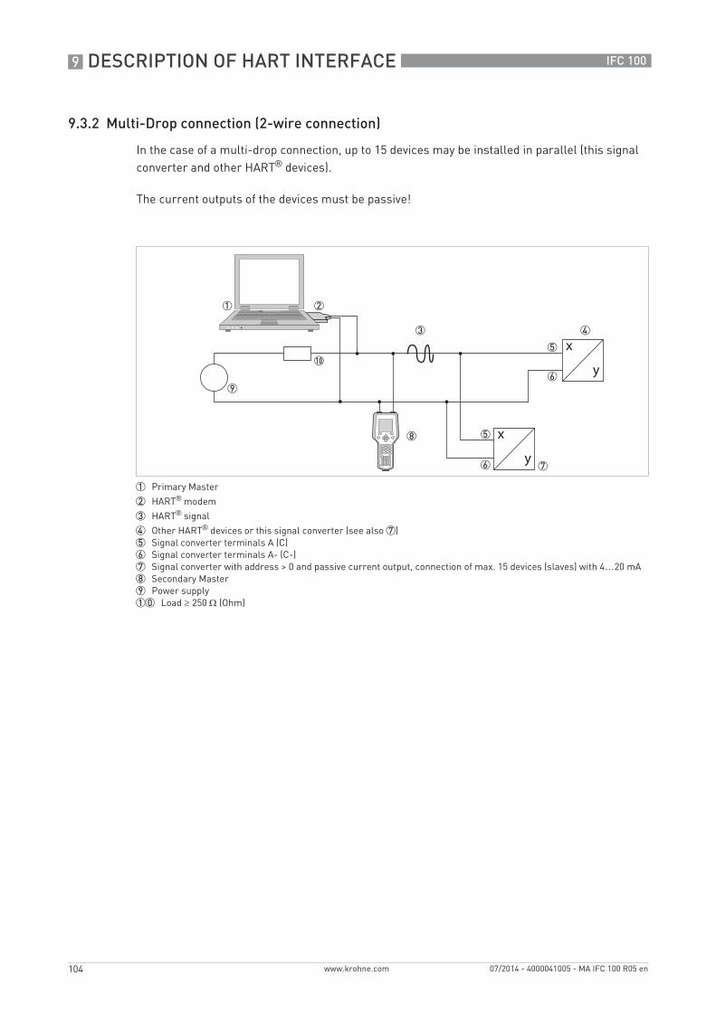
9 DESCRIPTION OF HART INTERFACE
104
IFC 100
www.krohne.com 07/2014 - 4000041005 - MA IFC 100 R05 en
9.3.2 Multi-Drop connection (2-wire connection)
In the case of a multi-drop connection, up to 15 devices may be installed in parallel (this signal converter and other HART® devices).
The current outputs of the devices must be passive!
1 Primary Master
2 HART® modem
3 HART® signal
4 Other HART® devices or this signal converter (see also 7)5 Signal converter terminals A (C)6 Signal converter terminals A- (C-)7 Signal converter with address > 0 and passive current output, connection of max. 15 devices (slaves) with 4…20 mA8 Secondary Master9 Power supply10 Load ≥ 250 Ω (Ohm)
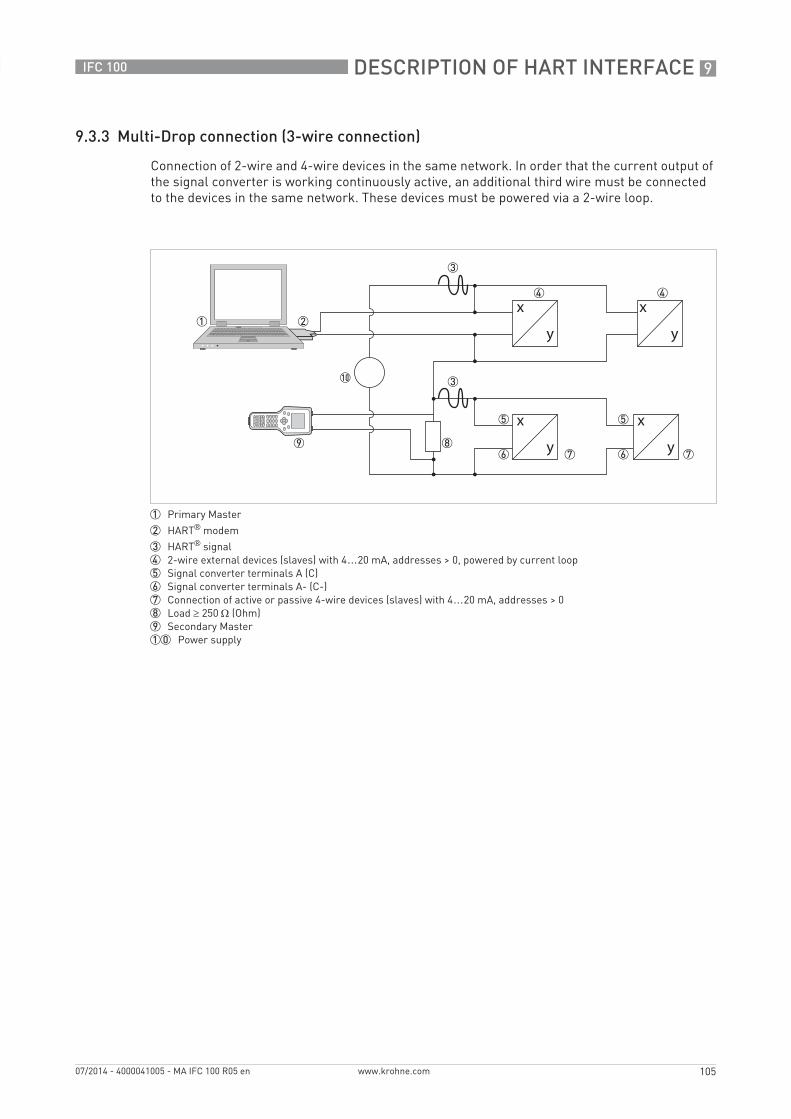
DESCRIPTION OF HART INTERFACE 9
105
IFC 100
www.krohne.com07/2014 - 4000041005 - MA IFC 100 R05 en
9.3.3 Multi-Drop connection (3-wire connection)
Connection of 2-wire and 4-wire devices in the same network. In order that the current output of the signal converter is working continuously active, an additional third wire must be connected to the devices in the same network. These devices must be powered via a 2-wire loop.
1 Primary Master
2 HART® modem
3 HART® signal4 2-wire external devices (slaves) with 4…20 mA, addresses > 0, powered by current loop5 Signal converter terminals A (C)6 Signal converter terminals A- (C-)7 Connection of active or passive 4-wire devices (slaves) with 4…20 mA, addresses > 08 Load ≥ 250 Ω (Ohm)9 Secondary Master10 Power supply
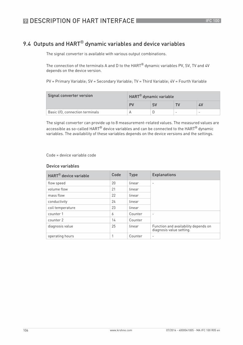
9 DESCRIPTION OF HART INTERFACE
106
IFC 100
www.krohne.com 07/2014 - 4000041005 - MA IFC 100 R05 en
9.4 Outputs and HART® dynamic variables and device variables
The signal converter is available with various output combinations.
The connection of the terminals A and D to the HART® dynamic variables PV, SV, TV and 4V depends on the device version.
PV = Primary Variable; SV = Secondary Variable; TV = Third Variable; 4V = Fourth Variable
The signal converter can provide up to 8 measurement-related values. The measured values are accessible as so-called HART® device variables and can be connected to the HART® dynamic variables. The availability of these variables depends on the device versions and the settings.
Code = device variable code
Device variables
Signal converter version HART® dynamic variable
PV SV TV 4V
Basic I/O, connection terminals A D - -
HART® device variable Code Type Explanations
flow speed 20 linear -
volume flow 21 linear
mass flow 22 linear
conductivity 24 linear
coil temperature 23 linear
counter 1 6 Counter -
counter 2 14 Counter
diagnosis value 25 linear Function and availability depends on diagnosis value setting.
operating hours 1 Counter -
DESCRIPTION OF HART INTERFACE 9
107
IFC 100
www.krohne.com07/2014 - 4000041005 - MA IFC 100 R05 en
For the dynamic variables connected to the linear analogue outputs for current and/or frequency, the assignment of the device variables takes place by selecting the linear measurement for these outputs under the appropriate function of the signal converter. It follows that the dynamic variables connected to current or frequency outputs can only be assigned to the linear HART® device variables.
The HART® dynamic variable PV is always connected to the HART® current output which is, for example, assigned to the volume flow.
A totaliser device variable can thus not be assigned to the dynamic variable PV because the PV is always connected to the HART® current output.
Such correlations do not exist for dynamic variables not connected to linear analogue outputs. Both linear and totaliser device variables can be assigned.
The totaliser device variables can only be assigned to the dynamic variables SV, TV and 4V if the connected output is not a current or frequency output.
9.5 Parameter for the basic configuration
There are parameters, such as counter 1 or 2, and a selection of the diagnosis values, that require a warm start for the device following data changes in order to update dependent unit parameters, for example, before other parameters are written.
Depending on the characteristic of the HART® host system, e.g. online/offline mode, these parameters are treated differently. See the following section for more detailed information.
9 DESCRIPTION OF HART INTERFACE
108
IFC 100
www.krohne.com 07/2014 - 4000041005 - MA IFC 100 R05 en
9.6 Field Communicator 375/475 (FC 375/475)
The Field Communicator is a hand terminal from Emerson Process Management that is designed to configure HART® and Foundation Fieldbus devices. Device Descriptions (DDs) are used to integrate different devices into the Field Communicator.
9.6.1 Installation
The HART® Device Description for the signal converter must be installed on the Field Communicator. Otherwise only the functions of a generic DD are available to the user and the entire device control is not possible. A "Field Communicator Easy Upgrade Programming Utility" is required to install the DDs on the Field Communicator.
The Field Communicator must be equipped with a system card with "Easy Upgrade Option". For details consult the Field Communicator User’s Manual.
9.6.2 Operation
Operating the signal converter via the Field Communicator is very similar to manual device control using the keyboard.
Limitation: The service menu parameters for the device are not supported and a simulation is only possible for current outputs. The online help for each parameter contains its function number as a reference to the local device display.
Parameter protection for custody transfer is the same as on the device's local display. Other specific protective functions such as the passwords for the quick setup menu and the setup menu are not supported with HART®.
The Field Communicator always saves a complete configuration for the exchange with AMS, see Appendix A. However, in the offline configuration and when sending to the device, the Field Communicator only takes into account a partial parameter set (like the standard configuration of the old HART® Communicator 275).
9.6.3 Parameter for the basic configuration
In online mode, counter measurements and the diagnosis value can be set using special methods, see Appendix A. In offline mode, these parameters are read-only. However, when transferring the offline configuration, this data is also written to the device.
INFORMATION!For more detailed information see Appendix A, Menu tree for Basic DD.
DESCRIPTION OF HART INTERFACE 9
109
IFC 100
www.krohne.com07/2014 - 4000041005 - MA IFC 100 R05 en
9.7 Asset Management Solutions (AMS)
The Asset Management Solutions Device Manager (AMS) is a PC program from Emerson Process Management which is designed to configure and manage HART®, PROFIBUS and Foundation-Fieldbus devices. Device Descriptions (DDs) are used to integrate different devices into the AMS.
9.7.1 Installation
If the signal converter Device Description has not yet been installed on the AMS system, a so-called Installation Kit HART® AMS is required. It is available for download from the website or on CD ROM.
For installation with the Installation Kit refer to the "AMS Intelligent Device Manager Books Online" section "Basic Functionality / Device Information / Installing Device Types".
9.7.2 Operation
Due to AMS requirements and conventions, there are differences when operating the signal converter with AMS and operating using the local keyboard. The service menu parameters are not supported and simulation is only possible for current outputs. The online help for each parameter contains its function number as a reference to the local device display.
Parameter protection for custody transfer is the same as on the device's local display. Other specific protective functions such as the passwords for the "quick setup" menu and the "setup" menu are not supported with HART®.
9.7.3 Parameter for the basic configuration
In online mode, the measurements for counters and diagnosis values can be changed by using the appropriate methods in the basic configuration menu. These parameters are read-only in offline mode.
INFORMATION!Please read the "readme.txt", which is also contained in the Installation Kit.
INFORMATION!For more detailed information see Appendix B, Menu tree for AMS.
9 DESCRIPTION OF HART INTERFACE
110
IFC 100
www.krohne.com 07/2014 - 4000041005 - MA IFC 100 R05 en
9.8 Field Device Manager (FDM)
A Field Device Manager (FDM) is basically a PC program from Honeywell used to configure HART®, PROFIBUS and Foundation Fieldbus devices. Device Descriptions (DDs) are used to integrate different devices into the FDM.
9.8.1 Installation
If the signal converter Device Description has not yet been installed on the FDM system, the Device Description is required in binary format and is available for download from the website or on CD ROM.
See the section regarding Managing DDs in the FDM User Guide for information on installing the Device Descriptions in binary format.
9.8.2 Operation
Operating the signal converter via the Field Device Manager is very similar to manual device control using the keyboard.
Limitation: The Service Menu parameters for the device are not supported and a simulation is only possible for current outputs. The online help for each parameter contains its function number as a reference to the local device display.
Parameter protection for custody transfer is the same as on the device's local display. Other specific protective functions such as the passwords for the quick setup menu and the setup menu are not supported with HART®.
9.9 Process Device Manager (PDM)
The Process Device Manager (PDM) is a Siemens PC program designed to configure HART® and PROFIBUS devices. Device Descriptions (DDs) are used to integrate different devices into the PDM.
9.9.1 Installation
If the signal converter Device Description has not yet been installed on the PDM system, a so-called Device Install HART® PDM is required for the signal converter. This is available for download from the website or on CD-ROM.
For installation under PDM V 5.2, see PDM manual, section 11.1 - Install device / Integrate device into SIMATIC PDM with Device Install.
For installation under PDM V 6.0, see PDM manual, Section 13 - Integrating devices.
Please also read the "readme.txt", which is also contained in the Installation Kit.
INFORMATION!For more detailed information see Appendix A, Menu tree for Basic DD.
DESCRIPTION OF HART INTERFACE 9
111
IFC 100
www.krohne.com07/2014 - 4000041005 - MA IFC 100 R05 en
9.9.2 Operation
Due to PDM requirements and conventions, there are differences when operating the signal converter with PDM and operating using the local keyboard. The service menu parameters are not supported and simulation is only possible for current outputs. The online help for each parameter contains its function number as a reference to the local device display.
Parameter protection for custody transfer is the same as on the device's local display. Other specific protective functions such as the passwords for the "quick setup" menu and the "setup" menu are not supported with HART®.
9.9.3 Parameter for the basic configuration
The counter measurements and the diagnosis values can be set directly in the PDM offline table. The dependent unit parameters are automatically updated. However, automatic updating is not possible in online dialogues of the PDM parameter table.
INFORMATION!For more detailed information see Appendix C, Menu tree for PDM.
9 DESCRIPTION OF HART INTERFACE
112
IFC 100
www.krohne.com 07/2014 - 4000041005 - MA IFC 100 R05 en
9.10 Field Device Tool / Device Type Manager (FDT / DTM)
A Field Device Tool Container (FDT Container) is basically a PC program used to configure HART®, PROFIBUS and Foundation Fieldbus devices. To adapt to different devices, an FDT container uses a so-called Device Type Manager (DTM).
9.10.1 Installation
If the Device Type Manager for the signal converter has not yet been installed on the Field Device Tool Container, setup is required and is available for download from the website or on CD-ROM. See the supplied documentation for information on how to install and set up the DTM.
9.10.2 Operation
Operating the signal converter via DTM is very similar to manual device control using the keyboard. See also local device display.
9.11 Appendix A: HART® menu tree for Basic-DD
Abbreviations of the following tables:
• Opt Optional, depending on device version and configuration
• Rd Read only
• Cust Custody lock protection
• Loc Local, affects only DD host views
INFORMATION!The numbering in the following table may change depending on the version of the signal converter!
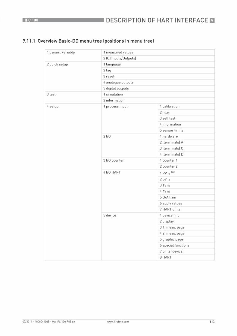
DESCRIPTION OF HART INTERFACE 9
113
IFC 100
www.krohne.com07/2014 - 4000041005 - MA IFC 100 R05 en
9.11.1 Overview Basic-DD menu tree (positions in menu tree)
1 dynam. variable 1 measured values
2 IO (Inputs/Outputs)
2 quick setup 1 language
2 tag
3 reset
4 analogue outputs
5 digital outputs
3 test 1 simulation
2 information
4 setup 1 process input 1 calibration
2 filter
3 self test
4 information
5 sensor limits
2 I/O 1 hardware
2 (terminals) A
3 (terminals) C
4 (terminals) D
3 I/O counter 1 counter 1
2 counter 2
4 I/O HART 1 PV is Rd
2 SV is
3 TV is
4 4V is
5 D/A trim
6 apply values
7 HART units
5 device 1 device info
2 display
3 1. meas. page
4 2. meas. page
5 graphic page
6 special functions
7 units (device)
8 HART

9 DESCRIPTION OF HART INTERFACE
114
IFC 100
www.krohne.com 07/2014 - 4000041005 - MA IFC 100 R05 en
9.11.2 Basic-DD menu tree (details for settings)
1 dynam. variable1 measurements 1 volume flow / 2 mass flow / 3 flow speed /
4 conductivity / 5 coil temperature / 6 counter 1 Opt / 7 counter 2 Opt /8 diagnosis value Opt
2 IO (Inputs/Outputs) 1 A Opt / 2 % range A Opt / 3 D Opt / 4 % range D Opt
2 quick setup1 language -
2 tag -
3 reset 1 reset errors / 2 reset counter 1 Cust /3 reset counter 2 Cust
4 analogue outputs 1 measurement A Cust / 2 unit Cust / 3 range min A Cust /4 range max A Cust / 5 lfc threshold Cust / 6 lfc hysteresis Cust /7 time constant Cust
5 digital outputs 1 measurement D Opt, Cust / 2 pulse value unit Opt, Cust /3 value p. pulse D Opt, Cust / 4 lfc threshold Opt, Cust / 5 lfc hysteresis Opt, Cust
3 test1 simulation 1 simul. current A Opt / 2 simul. frequency D Opt
2 information 1 C number / 2 info process input / 3 SW.REV.MS / 4 SW.REV.UIS
4 setup1 process input 1 calibration 1 autom. zero calib. Cust / 2 zero calibration Cust /
3 size Cust / 4 GKL Opt, Cust /5 coil resistance Rsp Cust / 6 density Cust /7 target conduct. Cust / 8 EF electr. factor Cust /9 field frequency Cust / 10 select settling Cust /11 settling time Opt Cust / 12 line frequency Cust
2 filter 1 limitation min Cust / 2 limitation max Cust /3 flow direction Cust / 4 time constant /5 pulse filter Cust / 6 pulse width Opt, Cust /7 pulse limitation Opt, Cust / 8 noise filter Cust /9 noise level Opt, Cust / 10 noise suppression Opt, Cust /11 lfc threshold Cust / 12 lfc hysteresis Cust
3 self test 1 empty pipe Cust / 2 limit empty pipe Opt, Cust /3 electrode noise Cust /4 limit electr. noise Opt, Cust /5 settling of field Cust /6 diagnosis value Rd / 7 select diagnosis

DESCRIPTION OF HART INTERFACE 9
115
IFC 100
www.krohne.com07/2014 - 4000041005 - MA IFC 100 R05 en
4 information 1 liner / 2 electr. material /3 serial no. sensor Rd / 4 V no. sensor Rd /5 sensor electr. info
5 sensor limits 1 volume flow 1 upper snsr limit Rd /2 lower snsr limit Rd /3 minimum span Rd
2 mass flow
3 flow speed
4 conductivity
5 coil temperature
2 I/O 1 hardware 1 terminals A Cust / 2 terminals C Cust / 3 terminals D Cust
2 A3 C4 D
Current Output Current Output Current Output Current Output OptOptOptOpt:1 range 0% Cust / 2 range 100% Cust /3 extended range min Cust / 4 extended range max Cust /5 error current Cust / 6 error condition Cust /7 measurement Cust / 8 range min Cust /9 range max Cust / 10 polarity Cust /11 limitation min Cust / 12 limitation max Cust /13 lfc threshold Cust / 14 lfc hysteresis Cust /15 time constant Cust / 16 special function Cust /17 rc threshold Opt, Cust / 18 rc hysteresis Opt, Cust /19 information
frequency output frequency output frequency output frequency output OptOptOptOpt:1 pulse shape Cust / 2 pulse width Cust /3 100% pulse rate Cust / 4 measurement Cust /5 range min Cust / 6 range max Cust /7 polarity Cust / 8 limitation min Cust /9 limitation max Cust / 10 lfc threshold Cust /11 lfc hysteresis Cust / 12 time constant Cust /13 invert signal Cust / 14 special function Opt, Cust /15 information
pulse output pulse output pulse output pulse output OptOptOptOpt:1 pulse shape Cust / 2 pulse width Cust /3 max. pulse rate Cust / 4 measurement Cust /5 pulse value unit / 6 value p. pulse /7 polarity Cust / 8 lfc threshold Cust /9 lfc hysteresis Cust / 10 time constant /11 Invert Signal Cust / 12 Special Function Opt, Cust /13 information
status output status output status output status output OptOptOptOpt:1 mode / 2 output A Opt /2 output C Opt / 2 output D Opt /3 invert signal / 4 information
limit switch limit switch limit switch limit switch OptOptOptOpt:1 measurement / 2 threshold / 3 hysteresis /4 polarity / 5 time constant / 6 invert signal / 7 information
control input control input control input control input OptOptOptOpt:1 mode Cust / 2 invert signal / 3 information
3 I/O counter 1 counter 1 1 funct. of counter Cust / 2 measurement Cust, Rd /3 select measurement Opt, Cust / 4 lfc threshold Opt, Cust /5 lfc hysteresis Opt, Cust / 6 time constant Opt, Cust /7 preset value Opt, Cust / 8 reset counter Opt, Cust /9 set counter Opt, Cust / 10 information
2 Totaliser 2
4 I/O HART 1 PV is Rd / 2 SV is / 3 TV is / 4 4V is / 5 D/A trim Cust /6 apply values Cust / 7 HART units
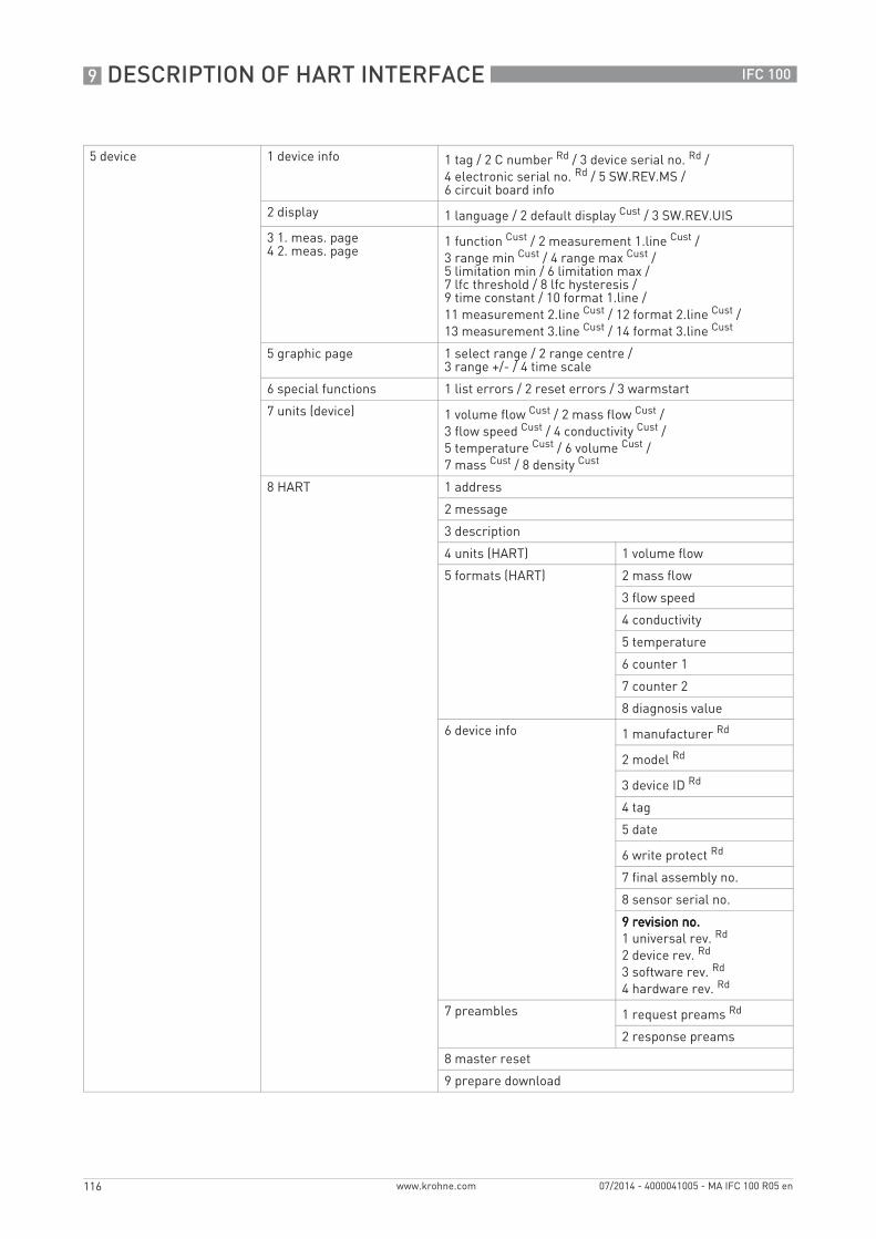
9 DESCRIPTION OF HART INTERFACE
116
IFC 100
www.krohne.com 07/2014 - 4000041005 - MA IFC 100 R05 en
5 device 1 device info 1 tag / 2 C number Rd / 3 device serial no. Rd /4 electronic serial no. Rd / 5 SW.REV.MS /6 circuit board info
2 display 1 language / 2 default display Cust / 3 SW.REV.UIS
3 1. meas. page4 2. meas. page
1 function Cust / 2 measurement 1.line Cust /3 range min Cust / 4 range max Cust /5 limitation min / 6 limitation max /7 lfc threshold / 8 lfc hysteresis /9 time constant / 10 format 1.line /11 measurement 2.line Cust / 12 format 2.line Cust /13 measurement 3.line Cust / 14 format 3.line Cust
5 graphic page 1 select range / 2 range centre /3 range +/- / 4 time scale
6 special functions 1 list errors / 2 reset errors / 3 warmstart
7 units (device) 1 volume flow Cust / 2 mass flow Cust /3 flow speed Cust / 4 conductivity Cust /5 temperature Cust / 6 volume Cust /7 mass Cust / 8 density Cust
8 HART 1 address
2 message
3 description
4 units (HART) 1 volume flow
5 formats (HART) 2 mass flow
3 flow speed
4 conductivity
5 temperature
6 counter 1
7 counter 2
8 diagnosis value
6 device info 1 manufacturer Rd
2 model Rd
3 device ID Rd
4 tag
5 date
6 write protect Rd
7 final assembly no.
8 sensor serial no.
9 revision no.9 revision no.9 revision no.9 revision no.1 universal rev. Rd
2 device rev. Rd
3 software rev. Rd
4 hardware rev. Rd
7 preambles 1 request preams Rd
2 response preams
8 master reset
9 prepare download
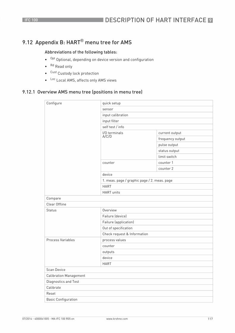
DESCRIPTION OF HART INTERFACE 9
117
IFC 100
www.krohne.com07/2014 - 4000041005 - MA IFC 100 R05 en
9.12 Appendix B: HART® menu tree for AMS
Abbreviations of the following tables:
• Opt Optional, depending on device version and configuration
• Rd Read only
• Cust Custody lock protection
• Loc Local AMS, affects only AMS views
9.12.1 Overview AMS menu tree (positions in menu tree)
Configure quick setup
sensor
input calibration
input filter
self test / info
I/O terminalsA/C/D
current output
frequency output
pulse output
status output
limit switch
counter counter 1
counter 2
device
1. meas. page / graphic page / 2. meas. page
HART
HART units
Compare
Clear Offline
Status Overview
Failure (device)
Failure (application)
Out of specification
Check request & Information
Process Variables process values
counter
outputs
device
HART
Scan Device
Calibration Management
Diagnostics and Test
Calibrate
Reset
Basic Configuration
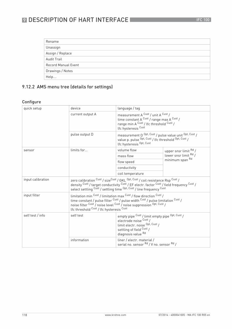
9 DESCRIPTION OF HART INTERFACE
118
IFC 100
www.krohne.com 07/2014 - 4000041005 - MA IFC 100 R05 en
9.12.2 AMS menu tree (details for settings)
Rename
Unassign
Assign / Replace
Audit Trail
Record Manual Event
Drawings / Notes
Help…
Configurequick setup device language / tag
current output A measurement A Cust / unit A Cust /time constant A Cust / range max A Cust /range min A Cust / lfc threshold Cust /lfc hysteresis Cust
pulse output D measurement D Opt, Cust / pulse value unit Opt, Cust /value p. pulse Opt, Cust / lfc threshold Opt, Cust /lfc hysteresis Opt, Cust
sensor limits for... volume flow upper snsr limit Rd /lower snsr limit Rd /minimum span Rd
mass flow
flow speed
conductivity
coil temperature
input calibration zero calibration Cust / sizeCust / GKL Opt, Cust / coil resistance Rsp Cust /density Cust / target conductivity Cust / EF electr. factor Cust / field frequency Cust /select settling Cust / settling time Opt, Cust / line frequency Cust
input filter limitation min Cust / limitation max Cust / flow direction Cust /time constant / pulse filter Cust / pulse width Cust / pulse limitation Cust /noise filter Cust / noise level Cust / noise suppression Opt, Cust /lfc threshold Cust / lfc hysteresis Cust
self test / info self test empty pipe Cust / limit empty pipe Opt, Cust /electrode noise Cust /limit electr. noise Opt, Cust /settling of field Cust /diagnosis value Rd
information liner / electr. material /serial no. sensor Rd / V no. sensor Rd /
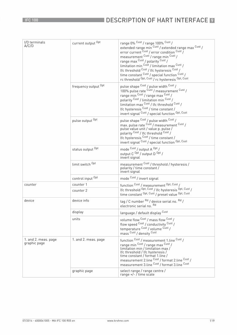
DESCRIPTION OF HART INTERFACE 9
119
IFC 100
www.krohne.com07/2014 - 4000041005 - MA IFC 100 R05 en
I/O terminalsA/C/D
current output Opt range 0% Cust / range 100% Cust /extended range min Cust / extended range max Cust /error current Cust / error condition Cust /measurement Cust / range min Cust /range max Cust / polarity Cust /limitation min Cust / limitation max Cust /lfc threshold Cust / lfc hysteresis Cust /time constant Cust / special function Cust /rc threshold Opt, Cust / rc hysteresis Opt, Cust
frequency output Opt pulse shape Cust / pulse width Cust /100% pulse rate Cust / measurement Cust /range min Cust / range max Cust /polarity Cust / limitation min Cust /limitation max Cust / lfc threshold Cust /lfc hysteresis Cust / time constant /invert signal Cust / special function Opt, Cust
pulse output Opt pulse shape Cust / pulse width Cust /max. pulse rate Cust / measurement Cust /pulse value unit / value p. pulse /polarity Cust / lfc threshold Cust /lfc hysteresis Cust / time constant /invert signal Cust / special function Opt, Cust
status output Opt mode Cust / output A Opt /output C Opt / output D Opt /invert signal
limit switch Opt measurement Cust / threshold / hysteresis /polarity / time constant /invert signal
control input Opt mode Cust / invert signal
counter counter 1 function Cust / measurement Opt, Cust /lfc threshold Opt, Cust / lfc hysteresis Opt, Cust /time constant Opt, Cust / preset value Opt, Cust
counter 2
device device info tag / C number Rd / device serial no. Rd /electronic serial no. Rd
display language / default display Cust
units volume flow Cust / mass flow Cust /flow speed Cust / conductivity Cust /temperature Cust / volume Cust /mass Cust / density Cust
1. and 2. meas. pagegraphic page
1. and 2. meas. page function Cust / measurement 1.line Cust /range min Cust / range max Cust /limitation min / limitation max /lfc threshold / lfc hysteresis /time constant / format 1.line /measurement 2.line Cust / format 2.line Cust /measurement 3.line Cust / format 3.line Cust
graphic page select range / range centre /range +/- / time scale
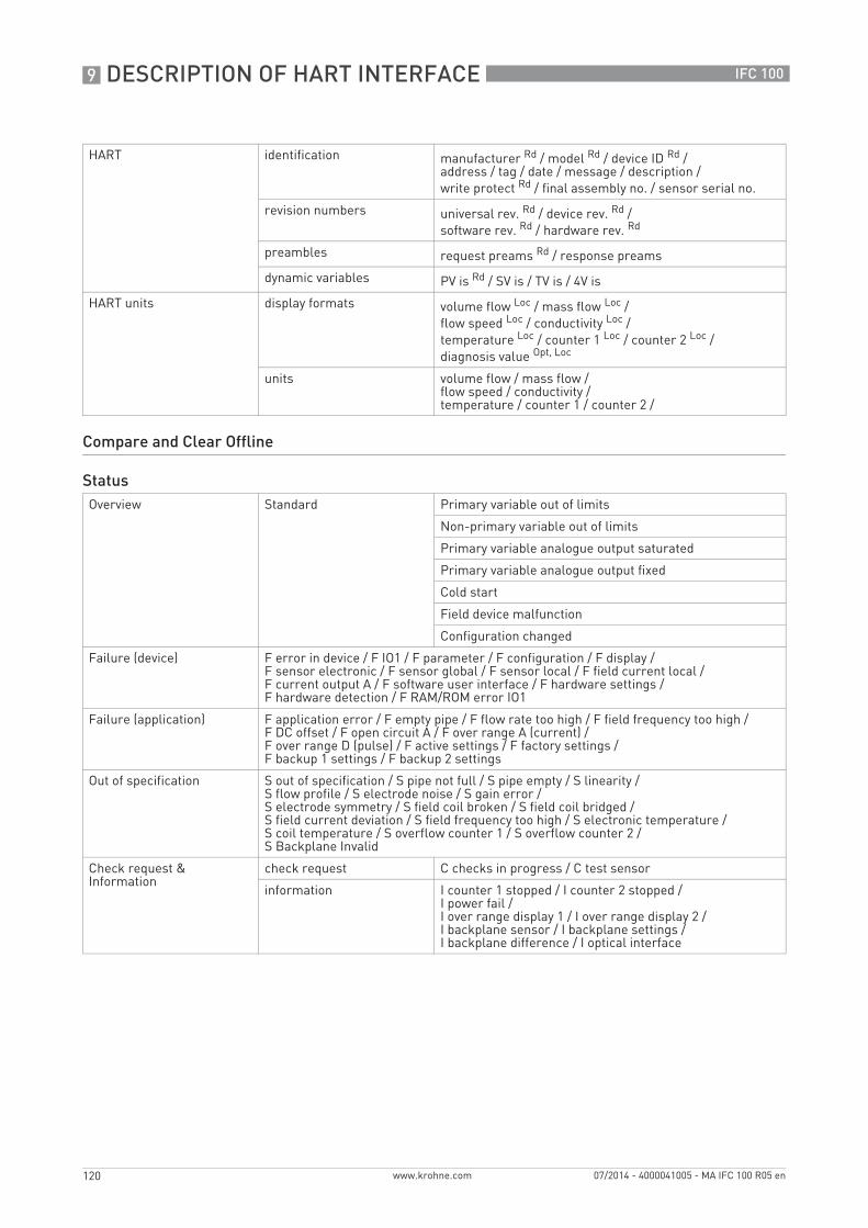
9 DESCRIPTION OF HART INTERFACE
120
IFC 100
www.krohne.com 07/2014 - 4000041005 - MA IFC 100 R05 en
HART identification manufacturer Rd / model Rd / device ID Rd /address / tag / date / message / description /write protect Rd / final assembly no. / sensor serial no.
revision numbers universal rev. Rd / device rev. Rd /software rev. Rd / hardware rev. Rd
preambles request preams Rd / response preams
dynamic variables PV is Rd / SV is / TV is / 4V is
HART units display formats volume flow Loc / mass flow Loc /flow speed Loc / conductivity Loc /temperature Loc / counter 1 Loc / counter 2 Loc /diagnosis value Opt, Loc
units volume flow / mass flow /flow speed / conductivity /temperature / counter 1 / counter 2 /
Compare and Clear Offline
StatusOverview Standard Primary variable out of limits
Non-primary variable out of limits
Primary variable analogue output saturated
Primary variable analogue output fixed
Cold start
Field device malfunction
Configuration changed
Failure (device) F error in device / F IO1 / F parameter / F configuration / F display /F sensor electronic / F sensor global / F sensor local / F field current local /F current output A / F software user interface / F hardware settings /F hardware detection / F RAM/ROM error IO1
Failure (application) F application error / F empty pipe / F flow rate too high / F field frequency too high /F DC offset / F open circuit A / F over range A (current) /F over range D (pulse) / F active settings / F factory settings /F backup 1 settings / F backup 2 settings
Out of specification S out of specification / S pipe not full / S pipe empty / S linearity /S flow profile / S electrode noise / S gain error /S electrode symmetry / S field coil broken / S field coil bridged /S field current deviation / S field frequency too high / S electronic temperature /S coil temperature / S overflow counter 1 / S overflow counter 2 /S Backplane Invalid
Check request & Information
check request C checks in progress / C test sensor
information I counter 1 stopped / I counter 2 stopped /I power fail /I over range display 1 / I over range display 2 /I backplane sensor / I backplane settings /I backplane difference / I optical interface

DESCRIPTION OF HART INTERFACE 9
121
IFC 100
www.krohne.com07/2014 - 4000041005 - MA IFC 100 R05 en
Process Variablesprocess values volume flow / mass flow / flow speed / conductivity / coil temperature / diagnosis value
Opt
counter counter 1 Opt / counter 2 Opt
outputs A Opt / % range A Opt / D Opt / % range D Opt
device tag Rd / description Rd
HART polling address Rd / device ID Rd
Scan Device
Calibration Management
Diagnostics and Test
simulation A Opt, Cust / simulation D Opt, Cust / circuit board info
Calibrate
autom. zero calibration Cust / D/A trim Cust / apply values Cust
Resetreset errors / reset configuration changed flag / master reset / warmstart / reset counter 1Cust / set counter 1 Cust / reset counter 2 Cust / set counter 2 Cust
Basic Configurationselect measurement counter 1 / select measurement counter 2 / select diagnosis value
Rename
Unassign
Assign / Replace
Audit Trail
Record Manual Event
Drawings / Notes
Help…
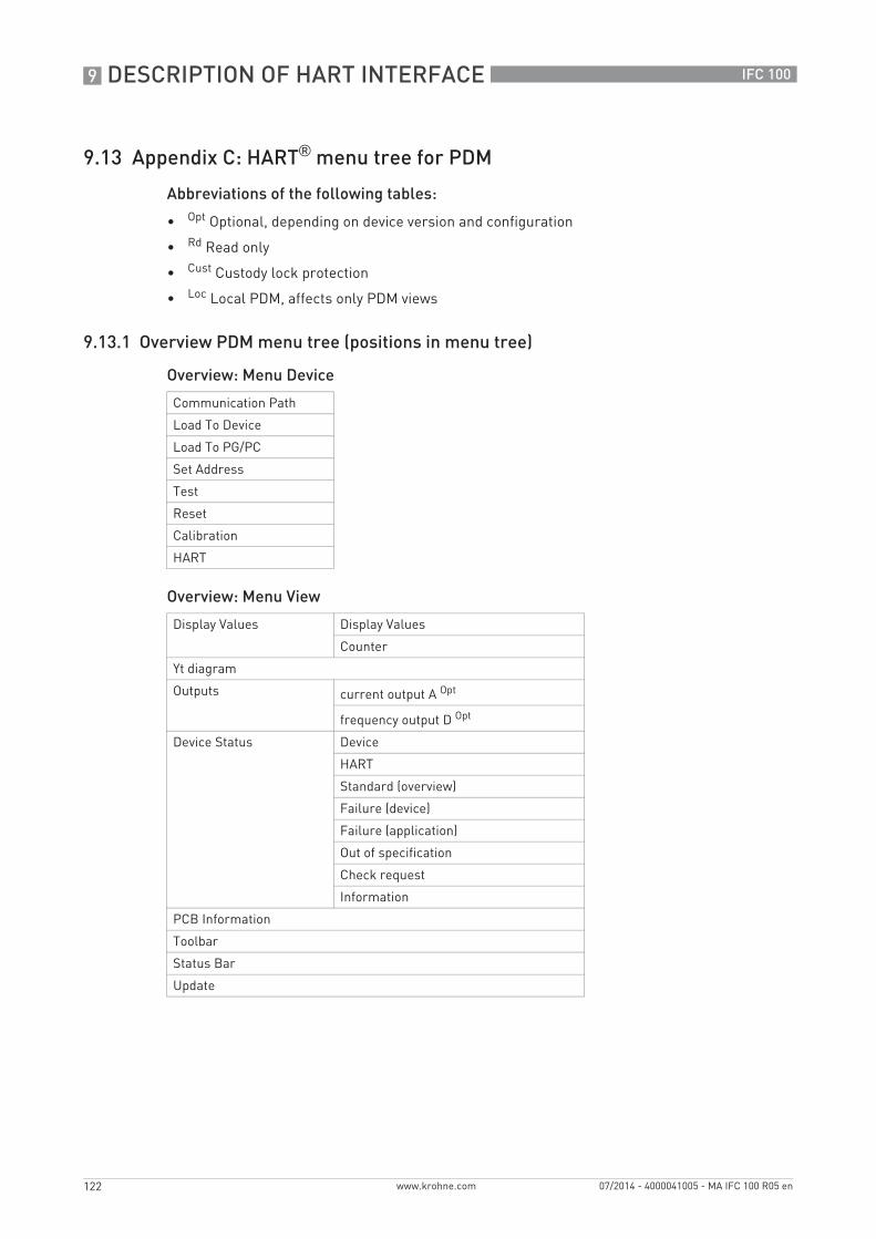
9 DESCRIPTION OF HART INTERFACE
122
IFC 100
www.krohne.com 07/2014 - 4000041005 - MA IFC 100 R05 en
9.13 Appendix C: HART® menu tree for PDM
Abbreviations of the following tables:
• Opt Optional, depending on device version and configuration
• Rd Read only
• Cust Custody lock protection
• Loc Local PDM, affects only PDM views
9.13.1 Overview PDM menu tree (positions in menu tree)
Overview: Menu Device
Overview: Menu View
Communication Path
Load To Device
Load To PG/PC
Set Address
Test
Reset
Calibration
HART
Display Values Display Values
Counter
Yt diagram
Outputs current output A Opt
frequency output D Opt
Device Status Device
HART
Standard (overview)
Failure (device)
Failure (application)
Out of specification
Check request
Information
PCB Information
Toolbar
Status Bar
Update
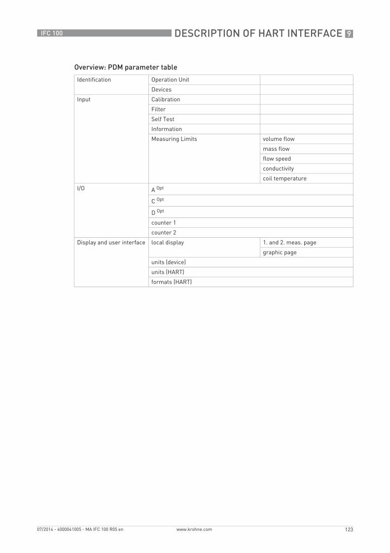
DESCRIPTION OF HART INTERFACE 9
123
IFC 100
www.krohne.com07/2014 - 4000041005 - MA IFC 100 R05 en
Overview: PDM parameter table
Identification Operation Unit
Devices
Input Calibration
Filter
Self Test
Information
Measuring Limits volume flow
mass flow
flow speed
conductivity
coil temperature
I/O A Opt
C Opt
D Opt
counter 1
counter 2
Display and user interface local display 1. and 2. meas. page
graphic page
units (device)
units (HART)
formats (HART)
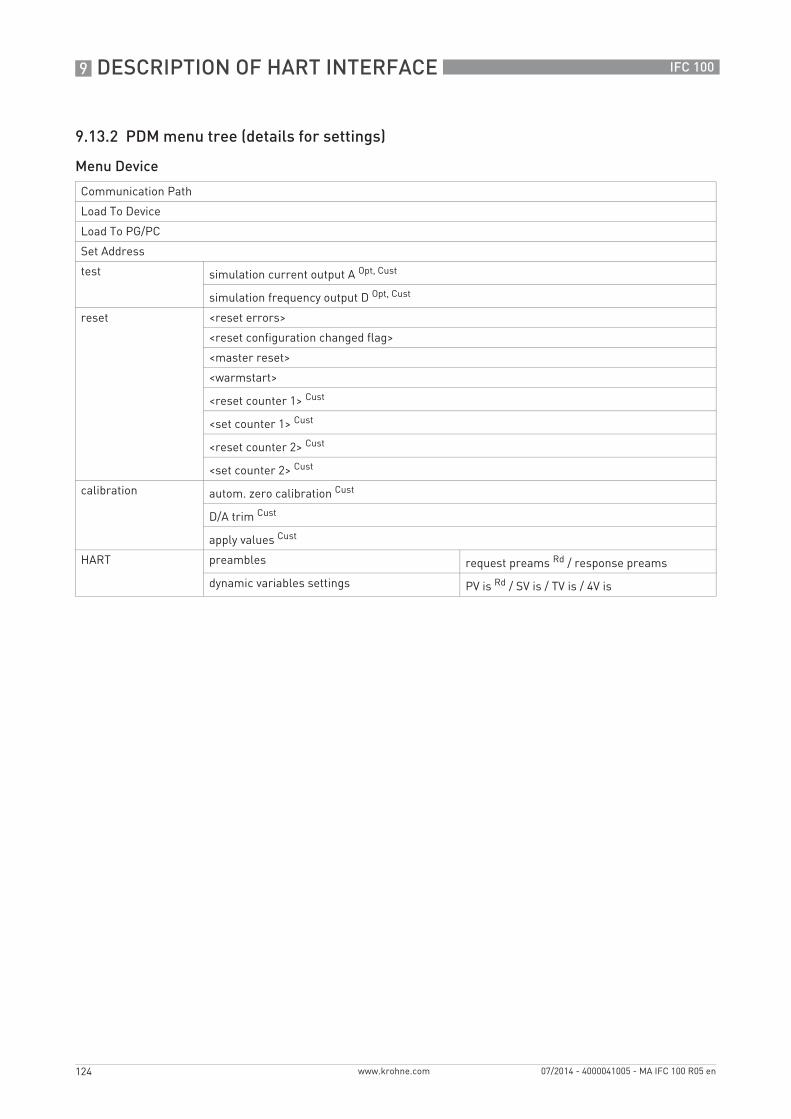
9 DESCRIPTION OF HART INTERFACE
124
IFC 100
www.krohne.com 07/2014 - 4000041005 - MA IFC 100 R05 en
9.13.2 PDM menu tree (details for settings)
Menu Device
Communication Path
Load To Device
Load To PG/PC
Set Address
test simulation current output A Opt, Cust
simulation frequency output D Opt, Cust
reset <reset errors>
<reset configuration changed flag>
<master reset>
<warmstart>
<reset counter 1> Cust
<set counter 1> Cust
<reset counter 2> Cust
<set counter 2> Cust
calibration autom. zero calibration Cust
D/A trim Cust
apply values Cust
HART preambles request preams Rd / response preams
dynamic variables settings PV is Rd / SV is / TV is / 4V is
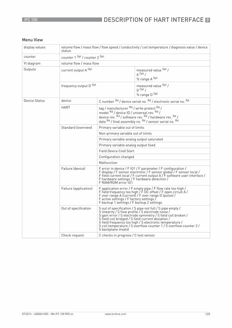
DESCRIPTION OF HART INTERFACE 9
125
IFC 100
www.krohne.com07/2014 - 4000041005 - MA IFC 100 R05 en
Menu View
display values volume flow / mass flow / flow speed / conductivity / coil temperature / diagnosis value / device status
counter counter 1 Opt / counter 2 Opt
Yt diagram volume flow / mass flow
Outputs current output A Opt measured value Opt /A Opt /% range A Opt
frequency output D Opt measured value Opt /D Opt /% range D Opt
Device Status device C number Rd / device serial no. Rd / electronic serial no. Rd
HART tag / manufacturer Rd / write protect Rd /model Rd / device ID / universal rev. Rd /device rev. Rd / software rev. Rd / hardware rev. Rd /date Rd / final assembly no. Rd / sensor serial no. Rd
Standard (overview) Primary variable out of limits
Non-primary variable out of limits
Primary variable analog output saturated
Primary variable analog output fixed
Field Device Cold Start
Configuration changed
Malfunction
Failure (device) F error in device / F IO1 / F parameter / F configuration /F display / F sensor electronic / F sensor global / F sensor local /F field current local / F current output A / F software user interface /F hardware settings / F hardware detection /F RAM/ROM error IO1
Failure (application) F application error / F empty pipe / F flow rate too high /F field frequency too high / F DC offset / F open circuit A /F over range A (current) / F over range D (pulse) /F active settings / F factory settings /F backup 1 settings / F backup 2 settings
Out of specification S out of specification / S pipe not full / S pipe empty /S linearity / S flow profile / S electrode noise /S gain error / S electrode symmetry / S field coil broken /S field coil bridged / S field current deviation /S field frequency too high / S electronic temperature /S coil temperature / S overflow counter 1 / S overflow counter 2 /S backplane invalid
Check request C checks in progress / C test sensor
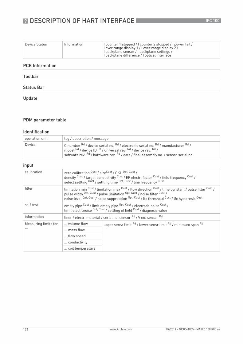
9 DESCRIPTION OF HART INTERFACE
126
IFC 100
www.krohne.com 07/2014 - 4000041005 - MA IFC 100 R05 en
PDM parameter table
Device Status Information I counter 1 stopped / I counter 2 stopped / I power fail /I over range display 1 / I over range display 2 /I backplane sensor / I backplane settings /I backplane difference / I optical interface
PCB Information
Toolbar
Status Bar
Update
Identificationoperation unit tag / description / message
Device C number Rd / device serial no. Rd / electronic serial no. Rd / manufacturer Rd / model Rd / device ID Rd / universal rev. Rd / device rev. Rd /software rev. Rd / hardware rev. Rd / date / final assembly no. / sensor serial no.
inputcalibration zero calibration Cust / sizeCust / GKL Opt, Cust /
density Cust / target conductivity Cust / EF electr. factor Cust / field frequency Cust /select settling Cust / settling time Opt, Cust / line frequency Cust
filter limitation min Cust / limitation max Cust / flow direction Cust / time constant / pulse filter Cust / pulse width Opt, Cust / pulse limitation Opt, Cust / noise filter Cust /noise level Opt, Cust / noise suppression Opt, Cust / lfc threshold Cust / lfc hysteresis Cust
self test empty pipe Cust / limit empty pipe Opt, Cust / electrode noise Cust /limit electr.noise Opt, Cust / settling of field Cust / diagnosis value
information liner / electr. material / serial no. sensor Rd / V no. sensor Rd
Measuring limits for ...
... volume flow upper sensr limit Rd / lower sensr limit Rd / minimum span Rd
... mass flow
... flow speed
... conductivity
... coil temperature

DESCRIPTION OF HART INTERFACE 9
127
IFC 100
www.krohne.com07/2014 - 4000041005 - MA IFC 100 R05 en
I/OI/O terminals A Cust / terminals C Cust / terminals D Cust
A / C / D Opt current output Opt range 0% Cust / range 100% Cust / extended range min Cust /extended range max Cust / error current Cust / error condition Cust /measurement Cust / range min Cust / range max Cust /polarity Cust / limitation min Cust / limitation max Cust /lfc threshold Cust / lfc hysteresis Cust / time constant /special function Cust / rc threshold Opt, Cust / rc hysteresis Opt, Cust
frequency output Opt pulse shape Cust / pulse width Cust /100% pulse rate Cust / measurement Cust /range min Cust / range max Cust /polarity Cust / limitation min Cust / limitation max Cust /lfc threshold Cust / lfc hysteresis Cust / time constant /invert signal Cust / special function Opt, Cust
pulse output Opt pulse shape Cust / pulse width Cust /max pulse rate Cust / measurement Cust /pulse value unit / value p. pulse / polarity Cust /lfc threshold Cust / lfc hysteresis Cust / time constant /invert signal Cust / special function Opt, Cust
status output Opt mode / output A Opt / output C Opt /output D Opt / invert signal
limit switch Opt measurement / threshold / hysteresis / polarity /time constant / invert signal
control input Opt mode Cust / invert signal
counter counter 1 function Cust / measurement Opt /lfc threshold Cust /lfc hysteresis Cust /time constant Opt / preset value Opt
counter 2
Display and user interfacelocal display language / default display Opt
1. and 2. meas. page function Cust / measurement 1.line Cust / range min Cust / range max Cust /limitation min / limitation max / lfc threshold / lfc hysteresis / time constant /format 1.line / measurement 2.line Cust / format 2.line Cust / measurement 3.line Cust /format 3.line Cust
graphic page select range / range centre / range +/- / time scale
Units (device) unit for ... volume flow Cust / mass flow Cust /flow speed / conductivity /temperature / volume Cust / mass Cust / density Cust
Units (HART) unit for ... volume flow / mass flow /flow speed / conductivity /coil temperature / counter 1 / counter 2
Formats (HART) format for ... volume flow Loc / mass flow Loc /flow speed Loc / conductivity Loc /coil temperature Loc / counter 1 Loc /counter 2 Loc / diagnosis value Opt, Loc

KROHNE product overview
• Electromagnetic flowmeters
• Variable area flowmeters
• Ultrasonic flowmeters
• Mass flowmeters
• Vortex flowmeters
• Flow controllers
• Level meters
• Temperature assemblies
• Pressure transmitters
• Analysis products
• Products and systems for the oil & gas industry
• Measuring systems for the marine industry
Head Office KROHNE Messtechnik GmbHLudwig-Krohne-Str. 547058 Duisburg (Germany)Tel.:+49 203 301 0Fax:+49 203 301 103 89 [email protected]
© K
RO
HN
E 07
/201
4 -
4000
0410
05 -
MA
IFC
100
R05
en
- Su
bjec
t to
chan
ge w
ithou
t not
ice.
The current list of all KROHNE contacts and addresses can be found at:www.krohne.com