identification for industrial control panels and...
TRANSCRIPT
IDENTIFICATION FOR INDUSTRIAL CONTROL PANELS AND INDUSTRIAL AUTOMATION
November 2016 | By Todd Fries
2
W h i t e P a p e r : IDENT I F ICAT ION FOR INDUSTR IAL CONTROL PANELS AND INDUSTR IAL AUTOMAT ION
IDENTIFICATION FOR INDUSTRIAL CONTROL PANELS AND INDUSTRIAL AUTOMATION Todd FriesMarketing Manager, Identification Systems – HellermannTyton North America
1.1 RELATED DOCUMENTSNational Electrical Code (NEC)
National Fire Protection Association (NFPA)
Occupational Safety and Health Administration (OSHA)
American National Standards Institute (ANSI)
NEC 2014 / NEC 2017
NFPA 70E -2012
NFPA 70B – 2010
NFPA 77 – 2007
NFPA 79 - 2012
ANSI Z535 - 2011
ANSI Z535.1 American National Standard for Safety Colors
ANSI Z535.2 American National Standard for Environmental and Facility Safety Signs
ANSI Z535.3 American National Standard for Criteria for Safety Symbols
ANSI Z535.4 American National Standard for Product Safety Signs and Labels
ANSI Z535.5 American National Standard for Safety Tags and Barricade Tapes (for Temporary Hazards)
ANSI Z535.6 American National Standard for Product Safety Information in Product Manuals, Instructions,
and other collateral materials
All OSHA 1910 - 2012 related regulations
Guide to application of the Machinery Directive 2006/42/IEC – 2nd edition – June 2010
UL 508A
DIVISION 01 SPECIFICATION
01 00 00
This document is designed to meet the requirements of the Authority Having Jurisdiction (AHJ) which
includes City, Electrical, Plumbing and Fire Protection inspectors.
PART 1 – DESCRIPTION
3
W h i t e P a p e r : IDENT I F ICAT ION FOR INDUSTR IAL CONTROL PANELS AND INDUSTR IAL AUTOMAT ION
1.2 SUMMARY
A. This document includes the following:
1. Bill of Materials
2. Quality Assurance
3. Coordination
4. General Materials
5. Equipment Labeling Instructions
6. Installation of Labels
7. Applications
8. Maintenance
1.3 BILL OF MATERIALS
A. This section includes the most common labeling items used in this standard.
1. 596-00412 .88” hole diameter white button label
2. 596-00414 1.2” hole diameter white button label
3. 596-00417 3” X 4” white foam nameplate rating label
4. 558-00309 1” wide white continuous vinyl roll for printing nameplates
5. 558-00307 1” wide black continuous vinyl roll for printing nameplates
6. 558-00313 2” wide white continuous vinyl roll for printing nameplates
7. 558-00311 2” wide black continuous vinyl roll for printing nameplates
8. 558-00312 2” wide red continuous vinyl roll for printing nameplates
9. 558-00330 3” total width pre-printed/ .75” wide orange header panel continuous vinyl roll
10. 558-00327 2” total width pre-printed/.5” wide orange header panel continuous vinyl roll
11. 558-00328 2” total width pre-printed/.5” wide yellow header panel continuous vinyl roll
12. 558-00331 3” total width pre-printed/.75” wide yellow header panel continuous vinyl roll
13. 558-00203 4” X 6” Pre-printed DANGER label with blank message panel
14. 596-00424 3” X 2” Pre-printed DANGER label with blank message panel
15. 596-00621 4” X 6” Pre-Printed WARNING label with blank message panel
16. 596-00622 3” X 2” Pre-printed WARNING label with blank message panel
17. 558-00204 4” X 6” Pre-printed NOTICE label with blank message panel
18. 558-00426 3” X 2” Pre-printed NOTICE label with blank message panel
19. 558-00247 4” X 6” Pre-printed CAUTION label with blank message panel
20. 558-00425 3” X 2” Pre-printed CAUTION label with blank message panel
21. 558-00336 1” wide orange continuous vinyl roll for voltage marking
22. 558-00337 2” wide orange continuous vinyl roll for voltage marking
23. 558-00338 3” wide orange continuous vinyl roll for voltage marking
24. 596-00378 1.35” X 2.75” Orange WARNING header with blank yellow triangle
25. 596-00379 1.35” X 2.75” Red DANGER header with blank yellow triangle
26. 596-00376 2.75” X 5.5” Orange WARNING header with blank yellow triangle
27. 596-00377 2.75” X 5.5” Red DANGER header with blankyellow triangle
4
W h i t e P a p e r : IDENT I F ICAT ION FOR INDUSTR IAL CONTROL PANELS AND INDUSTR IAL AUTOMAT ION
28. 556-00022 TagPrint Pro 3.0 label design software
29. 556-00022 TTM430 thermal transfer printer
30. 556-00189 White ribbon for TTM430 printer
31. TT822OUT Black ribbon for TTM430 printer
32. 556-00431 Cutter for TTM430 printer (needed to cut continuous label rolls)
33. TAG22T3-100B Self-laminating label for control panel wire marking
34. TAG26T6-100B Self-laminating label for control panel wire marking
35. TAG2T5-100B Self-laminating label for control panel wire marking
36. TAG51T3-100B Self-laminating label for control panel wire marking
37. 553-50002 .125”printable heat shrink tubing for control panel wire marking
38. 553-50004 .125”printable heat shrink tubing for control panel wire marking (slit)
39. 553-50009 .187”printable heat shrink tubing for control panel wire marking
40. 553-50011 .187”printable heat shrink tubing for control panel wire marking (slit)
41. 553-50016 .25” printable heat shrink tubing for control panel wire marking
42. 553-50019 .25”printable heat shrink tubing for control panel wire marking (slit)
43. 596-00380 .375”wide terminal block label
44. 596-00381 .50”wide terminal block label
45. 596-00382 1” X .5” white “Phase” label
46. 596-00383 1” X .5” black “Phase” label
47. 596-00000 3” X 5” Danger Lock Out Tag printable in two areas.
48. TCWM10 10 NEMA colors for color coding phases and conductors
49. RO175: Rite-on markers for conductors to be extended in the future.
1.4 QUALITY ASSURANCE
A. Comply with 2014 or 2017 National Electrical Code (NEC)
B. Comply with 2012 National Fire Protection Association (NFPA 70E)
C. Comply with ANSI Z535 – 2011 Requirements
D. Comply with OSHA requirements for electrical labeling
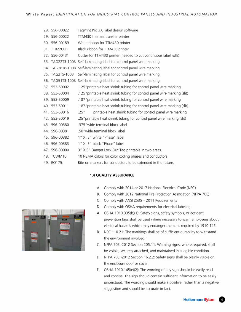
A. OSHA 1910.335(b)(1): Safety signs, safety symbols, or accident
prevention tags shall be used where necessary to warn employees about
electrical hazards which may endanger them, as required by 1910.145.
B. NEC 110.21: The markings shall be of sufficient durability to withstand
the environment involved.
C. NFPA 70E -2012 Section 205.11: Warning signs, where required, shall
be visible, securely attached, and maintained in a legible condition.
D. NFPA 70E -2012 Section 16.2.2: Safety signs shall be plainly visible on
the enclosure door or cover.
E. OSHA 1910.145(e)(2): The wording of any sign should be easily read
and concise. The sign should contain sufficient information to be easily
understood. The wording should make a positive, rather than a negative
suggestion and should be accurate in fact.
5
W h i t e P a p e r : IDENT I F ICAT ION FOR INDUSTR IAL CONTROL PANELS AND INDUSTR IAL AUTOMAT ION
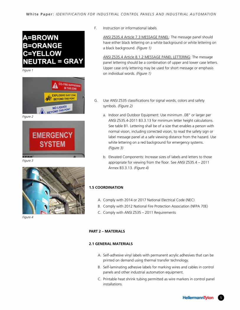
F. Instruction or informational labels
ANSI Z535.4 Article 7.3 MESSAGE PANEL: The message panel should
have either black lettering on a white background or white lettering on
a black background. (Figure 1)
ANSI Z535.4 Article 8.1.2 MESSAGE PANEL LETTERING: The message
panel lettering should be a combination of upper and lower case letters.
Upper case only lettering may be used for short message or emphasis
on individual words. (Figure 1)
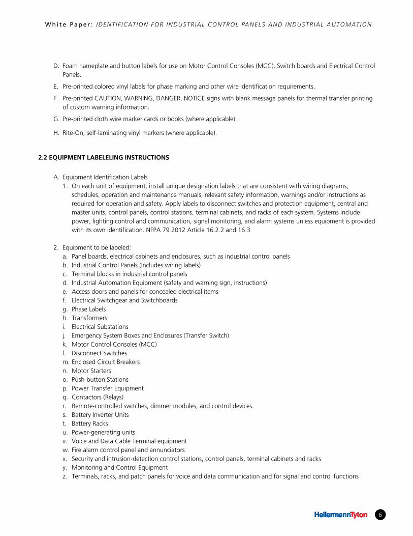
G. Use ANSI Z535 classifications for signal words, colors and safety
symbols. (Figure 2)
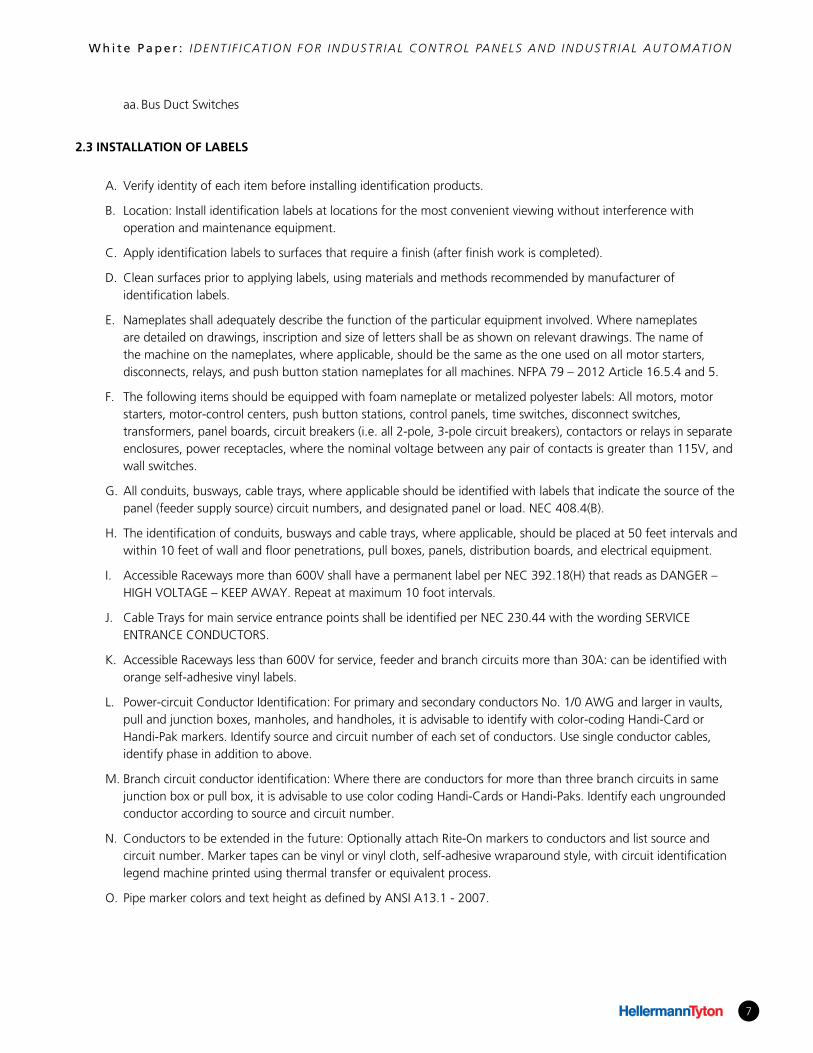
a. Indoor and Outdoor Equipment: Use minimum .08” or larger per
ANSI Z535.4-2011 B3.3.13 for minimum letter height calculations.
See table B1. Lettering shall be of a size that enables a person with
normal vision, including corrected vision, to read the safety sign or
label message panel at a safe viewing distance from the hazard. Use
white lettering on a red background for emergency systems.
(Figure 3)
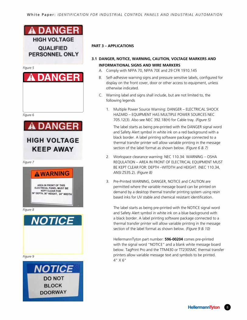
b. Elevated Components: Increase sizes of labels and letters to those
appropriate for viewing from the floor. See ANSI Z535.4 – 2011
Annex B3.3.13. (Figure 4)
1.5 COORDINATION
A. Comply with 2014 or 2017 National Electrical Code (NEC)
B. Comply with 2012 National Fire Protection Association (NFPA 70E)
C. Comply with ANSI Z535 – 2011 Requirements
PART 2 – MATERIALS
2.1 GENERAL MATERIALS
A. Self-adhesive vinyl labels with permanent acrylic adhesives that can be printed on demand using thermal transfer technology.
B. Self-laminating adhesive labels for marking wires and cables in control panels and other industrial automation equipment.
C. Printable heat shrink tubing permitted as wire markers in control panel installations.
Figure 1
Figure 2
Figure 3
Figure 4
6
W h i t e P a p e r : IDENT I F ICAT ION FOR INDUSTR IAL CONTROL PANELS AND INDUSTR IAL AUTOMAT ION
D. Foam nameplate and button labels for use on Motor Control Consoles (MCC), Switch boards and Electrical Control Panels.
E. Pre-printed colored vinyl labels for phase marking and other wire identification requirements.
F. Pre-printed CAUTION, WARNING, DANGER, NOTICE signs with blank message panels for thermal transfer printing of custom warning information.
G. Pre-printed cloth wire marker cards or books (where applicable).
H. Rite-On, self-laminating vinyl markers (where applicable).
2.2 EQUIPMENT LABELELING INSTRUCTIONS
A. Equipment Identification Labels1. On each unit of equipment, install unique designation labels that are consistent with wiring diagrams,
schedules, operation and maintenance manuals, relevant safety information, warnings and/or instructions as required for operation and safety. Apply labels to disconnect switches and protection equipment, central and master units, control panels, control stations, terminal cabinets, and racks of each system. Systems include power, lighting control and communication, signal monitoring, and alarm systems unless equipment is provided with its own identification. NFPA 79 2012 Article 16.2.2 and 16.3
2. Equipment to be labeled:a. Panel boards, electrical cabinets and enclosures, such as industrial control panelsb. Industrial Control Panels (Includes wiring labels)c. Terminal blocks in industrial control panelsd. Industrial Automation Equipment (safety and warning sign, instructions)e. Access doors and panels for concealed electrical itemsf. Electrical Switchgear and Switchboardsg. Phase Labels h. Transformersi. Electrical Substationsj. Emergency System Boxes and Enclosures (Transfer Switch)k. Motor Control Consoles (MCC)l. Disconnect Switchesm. Enclosed Circuit Breakersn. Motor Starterso. Push-button Stationsp. Power Transfer Equipmentq. Contactors (Relays)r. Remote-controlled switches, dimmer modules, and control devices.s. Battery Inverter Unitst. Battery Racksu. Power-generating unitsv. Voice and Data Cable Terminal equipmentw. Fire alarm control panel and annunciatorsx. Security and intrusion-detection control stations, control panels, terminal cabinets and racksy. Monitoring and Control Equipmentz. Terminals, racks, and patch panels for voice and data communication and for signal and control functions
6
7
W h i t e P a p e r : IDENT I F ICAT ION FOR INDUSTR IAL CONTROL PANELS AND INDUSTR IAL AUTOMAT ION
aa. Bus Duct Switches
2.3 INSTALLATION OF LABELS
A. Verify identity of each item before installing identification products.
B. Location: Install identification labels at locations for the most convenient viewing without interference with operation and maintenance equipment.
C. Apply identification labels to surfaces that require a finish (after finish work is completed).
D. Clean surfaces prior to applying labels, using materials and methods recommended by manufacturer of identification labels.
E. Nameplates shall adequately describe the function of the particular equipment involved. Where nameplates are detailed on drawings, inscription and size of letters shall be as shown on relevant drawings. The name of the machine on the nameplates, where applicable, should be the same as the one used on all motor starters, disconnects, relays, and push button station nameplates for all machines. NFPA 79 – 2012 Article 16.5.4 and 5.
F. The following items should be equipped with foam nameplate or metalized polyester labels: All motors, motor starters, motor-control centers, push button stations, control panels, time switches, disconnect switches, transformers, panel boards, circuit breakers (i.e. all 2-pole, 3-pole circuit breakers), contactors or relays in separate enclosures, power receptacles, where the nominal voltage between any pair of contacts is greater than 115V, and wall switches.
G. All conduits, busways, cable trays, where applicable should be identified with labels that indicate the source of the panel (feeder supply source) circuit numbers, and designated panel or load. NEC 408.4(B).
H. The identification of conduits, busways and cable trays, where applicable, should be placed at 50 feet intervals and within 10 feet of wall and floor penetrations, pull boxes, panels, distribution boards, and electrical equipment.
I. Accessible Raceways more than 600V shall have a permanent label per NEC 392.18(H) that reads as DANGER – HIGH VOLTAGE – KEEP AWAY. Repeat at maximum 10 foot intervals.
J. Cable Trays for main service entrance points shall be identified per NEC 230.44 with the wording SERVICE ENTRANCE CONDUCTORS.
K. Accessible Raceways less than 600V for service, feeder and branch circuits more than 30A: can be identified with orange self-adhesive vinyl labels.
L. Power-circuit Conductor Identification: For primary and secondary conductors No. 1/0 AWG and larger in vaults, pull and junction boxes, manholes, and handholes, it is advisable to identify with color-coding Handi-Card or Handi-Pak markers. Identify source and circuit number of each set of conductors. Use single conductor cables, identify phase in addition to above.
M. Branch circuit conductor identification: Where there are conductors for more than three branch circuits in same junction box or pull box, it is advisable to use color coding Handi-Cards or Handi-Paks. Identify each ungrounded conductor according to source and circuit number.
N. Conductors to be extended in the future: Optionally attach Rite-On markers to conductors and list source and circuit number. Marker tapes can be vinyl or vinyl cloth, self-adhesive wraparound style, with circuit identification legend machine printed using thermal transfer or equivalent process.
O. Pipe marker colors and text height as defined by ANSI A13.1 - 2007.
8
W h i t e P a p e r : IDENT I F ICAT ION FOR INDUSTR IAL CONTROL PANELS AND INDUSTR IAL AUTOMAT ION
PART 3 – APPLICATIONS
3.1 DANGER, NOTICE, WARNING, CAUTION, VOLTAGE MARKERS AND
INFORMATIONAL SIGNS AND WIRE MARKERSA. Comply with NFPA 70, NFPA 70E and 29 CFR 1910.145
B. Self-adhesive warning signs and pressure sensitive labels, configured for display on the front cover, door or other access to equipment, unless otherwise indicated.
C. Warning label and signs shall include, but are not limited to, the following legends
1. Multiple Power Source Warning: DANGER – ELECTRICAL SHOCK HAZARD – EQUIPMENT HAS MULTIPLE POWER SOURCES NEC 705.12(3). Also see NEC 392.18(H) for Cable tray. (Figure 5)
The label starts as being pre-printed with the DANGER signal word and Safety Alert symbol in white ink on a red background with a black border. A label printing software package connected to a thermal transfer printer will allow variable printing in the message section of the label format as shown below. (Figure 6 & 7)
2. Workspace clearance warning: NEC 110.34: WARNING – OSHA REQULATION – AREA IN FRONT OF ELECTRICAL EQUIPMENT MUST BE KEPT CLEAR FOR: DEPTH –WITDTH and HEIGHT. (NEC 110.34, ANSI Z535.2). (Figure 8)
3. Pre-Printed WARNING, DANGER, NOTICE and CAUTION are permitted where the variable message board can be printed on demand by a desktop thermal transfer printing system using resin based inks for UV stable and chemical resistant identification.
The label starts as being pre-printed with the NOTICE signal word and Safety Alert symbol in white ink on a blue background with a black border. A label printing software package connected to a thermal transfer printer will allow variable printing in the message section of the label format as shown below. (Figure 9 & 10)
HellermannTyton part number: 596-00204 comes pre-printed
with the signal word “NOTICE” and a blank white message board below. TagPrint Pro and the TTM430 or TT230SMC thermal transfer printers allow variable message text and symbols to be printed. 4” X 6”
DANGERFigure 5
Figure 6
Figure 7
Figure 8
Figure 9
9
W h i t e P a p e r : IDENT I F ICAT ION FOR INDUSTR IAL CONTROL PANELS AND INDUSTR IAL AUTOMAT ION
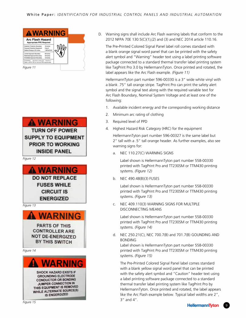
D. Warning signs shall include Arc Flash warning labels that conform to the 2012 NFPA 70E 130.5(C)(1),(2) and (3) and NEC 2014 article 110.16.
The Pre-Printed Colored Signal Panel label roll comes standard with a blank orange signal word panel that can be printed with the safety alert symbol and “Warning” header text using a label printing software package connected to a standard thermal transfer label printing system like TagPrint Pro 3.0 by HellermannTyton. Once printed and rotated, the label appears like the Arc Flash example. (Figure 11)
HellermannTyton part number 596-00330 is a 3” wide white vinyl with a blank .75” tall orange stripe. TagPrint Pro can print the safety alert symbol and the signal text along with the required variable text for Arc Flash Boundary, Nominal System Voltage and at least one of the following:
1. Available incident energy and the corresponding working distance
2. Minimum arc rating of clothing
3. Required level of PPD
4. Highest Hazard Risk Category (HRC) for the equipment
HellermannTyton part number 596-00327 is the same label but 2” tall with a .5” tall orange header. As further examples, also see warning signs for:
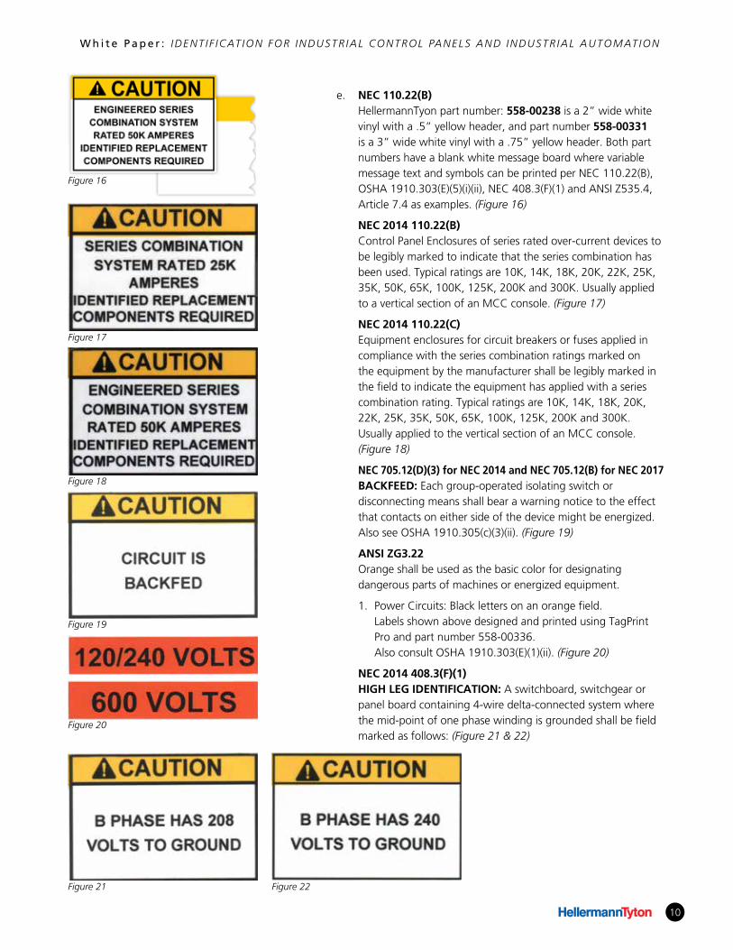
a. NEC 110.27(C) WARNING SIGNS
Label shown is HellermannTyton part number 558-00330 printed with TagPrint Pro and TT230SM or TTM430 printing systems. (Figure 12)
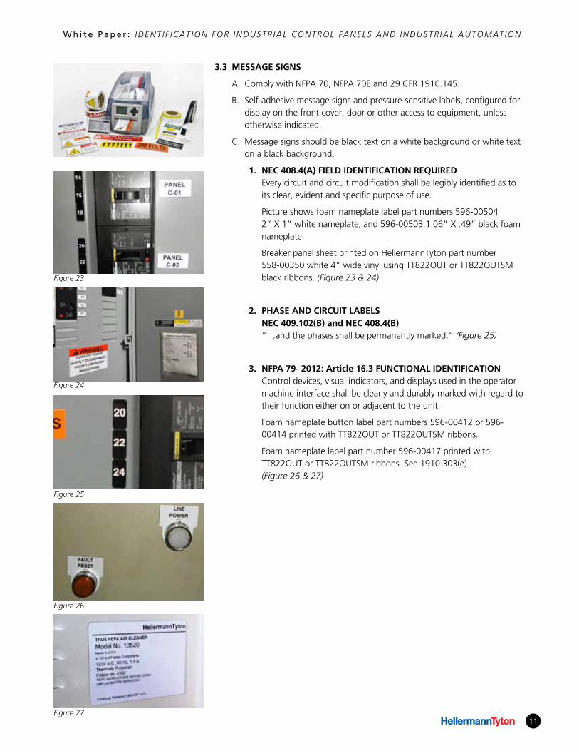
b. NEC 490.48(B)(3) FUSES
Label shown is HellermannTyton part number 558-00330 printed with TagPrint Pro and TT230SM or TTM430 printing systems. (Figure 13)
c. NEC 409.110(3) WARNING SIGNS FOR MULTIPLE DISCONNECTING MEANS
Label shown is HellermannTyton part number 558-00330 printed with TagPrint Pro and TT230SM or TTM430 printing systems. (Figure 14)
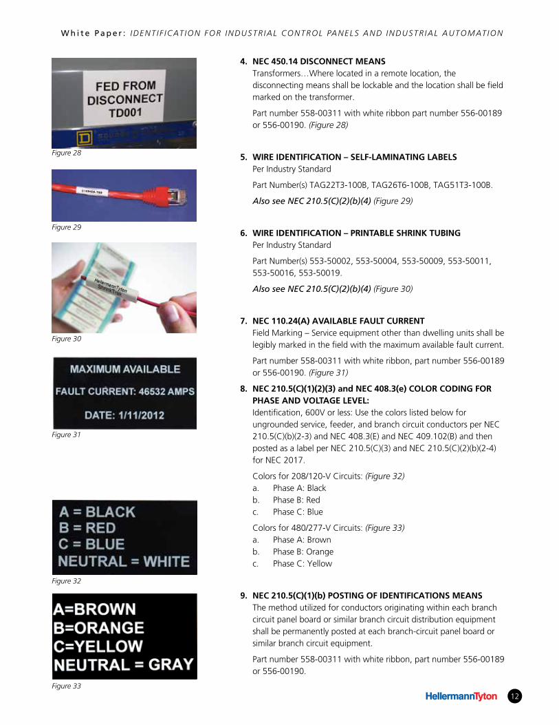
d. NEC 250.21(C), NEC 700.7(B) and 701.7(B) GOUNDING AND BONDING Label shown is HellermannTyton part number 558-00330 printed with TagPrint Pro and TT230SM or TTM430 printing systems. (Figure 15)
The Pre-Printed Colored Signal Panel label comes standard with a blank yellow signal word panel that can be printed with the safety alert symbol and “Caution” header text using a label printing software package connected to a standard thermal transfer label printing system like TagPrint Pro by HellermannTyton. Once printed and rotated, the label appears like the Arc Flash example below. Typical label widths are 2”, 3” and 4”.
Figure 11
Figure 12
Figure 13
Figure 14
Figure 15
10
W h i t e P a p e r : IDENT I F ICAT ION FOR INDUSTR IAL CONTROL PANELS AND INDUSTR IAL AUTOMAT ION
e. NEC 110.22(B) HellermannTyon part number: 558-00238 is a 2” wide white
vinyl with a .5” yellow header, and part number 558-00331 is a 3” wide white vinyl with a .75” yellow header. Both part numbers have a blank white message board where variable message text and symbols can be printed per NEC 110.22(B), OSHA 1910.303(E)(5)(i)(ii), NEC 408.3(F)(1) and ANSI Z535.4, Article 7.4 as examples. (Figure 16)
NEC 2014 110.22(B) Control Panel Enclosures of series rated over-current devices to
be legibly marked to indicate that the series combination has been used. Typical ratings are 10K, 14K, 18K, 20K, 22K, 25K, 35K, 50K, 65K, 100K, 125K, 200K and 300K. Usually applied to a vertical section of an MCC console. (Figure 17)
NEC 2014 110.22(C) Equipment enclosures for circuit breakers or fuses applied in
compliance with the series combination ratings marked on the equipment by the manufacturer shall be legibly marked in the field to indicate the equipment has applied with a series combination rating. Typical ratings are 10K, 14K, 18K, 20K, 22K, 25K, 35K, 50K, 65K, 100K, 125K, 200K and 300K. Usually applied to the vertical section of an MCC console. (Figure 18)
NEC 705.12(D)(3) for NEC 2014 and NEC 705.12(B) for NEC 2017 BACKFEED: Each group-operated isolating switch or
disconnecting means shall bear a warning notice to the effect that contacts on either side of the device might be energized. Also see OSHA 1910.305(c)(3)(ii). (Figure 19)
ANSI ZG3.22 Orange shall be used as the basic color for designating
dangerous parts of machines or energized equipment.
1. Power Circuits: Black letters on an orange field. Labels shown above designed and printed using TagPrint Pro and part number 558-00336. Also consult OSHA 1910.303(E)(1)(ii). (Figure 20)
NEC 2014 408.3(F)(1) HIGH LEG IDENTIFICATION: A switchboard, switchgear or panel board containing 4-wire delta-connected system where the mid-point of one phase winding is grounded shall be field marked as follows: (Figure 21 & 22)
Figure 16
Figure 17
Figure 18
Figure 19
Figure 20
Figure 21 Figure 22
11
W h i t e P a p e r : IDENT I F ICAT ION FOR INDUSTR IAL CONTROL PANELS AND INDUSTR IAL AUTOMAT ION
3.3 MESSAGE SIGNS
A. Comply with NFPA 70, NFPA 70E and 29 CFR 1910.145.
B. Self-adhesive message signs and pressure-sensitive labels, configured for display on the front cover, door or other access to equipment, unless otherwise indicated.
C. Message signs should be black text on a white background or white text on a black background.
1. NEC 408.4(A) FIELD IDENTIFICATION REQUIRED Every circuit and circuit modification shall be legibly identified as to its clear, evident and specific purpose of use.
Picture shows foam nameplate label part numbers 596-00504 2” X 1” white nameplate, and 596-00503 1.06” X .49” black foam nameplate.
Breaker panel sheet printed on HellermannTyton part number 558-00350 white 4” wide vinyl using TT822OUT or TT822OUTSM black ribbons. (Figure 23 & 24)
2. PHASE AND CIRCUIT LABELS NEC 409.102(B) and NEC 408.4(B) “…and the phases shall be permanently marked.” (Figure 25)
3. NFPA 79- 2012: Article 16.3 FUNCTIONAL IDENTIFICATION Control devices, visual indicators, and displays used in the operator machine interface shall be clearly and durably marked with regard to their function either on or adjacent to the unit.
Foam nameplate button label part numbers 596-00412 or 596-00414 printed with TT822OUT or TT822OUTSM ribbons.
Foam nameplate label part number 596-00417 printed with TT822OUT or TT822OUTSM ribbons. See 1910.303(e). (Figure 26 & 27)
Figure 23
Figure 24
Figure 25
Figure 26
Figure 27
12
W h i t e P a p e r : IDENT I F ICAT ION FOR INDUSTR IAL CONTROL PANELS AND INDUSTR IAL AUTOMAT ION
4. NEC 450.14 DISCONNECT MEANS Transformers…Where located in a remote location, the disconnecting means shall be lockable and the location shall be field marked on the transformer.
Part number 558-00311 with white ribbon part number 556-00189 or 556-00190. (Figure 28)
5. WIRE IDENTIFICATION – SELF-LAMINATING LABELS Per Industry Standard
Part Number(s) TAG22T3-100B, TAG26T6-100B, TAG51T3-100B.
Also see NEC 210.5(C)(2)(b)(4) (Figure 29)
6. WIRE IDENTIFICATION – PRINTABLE SHRINK TUBING Per Industry Standard
Part Number(s) 553-50002, 553-50004, 553-50009, 553-50011, 553-50016, 553-50019.
Also see NEC 210.5(C)(2)(b)(4) (Figure 30)
7. NEC 110.24(A) AVAILABLE FAULT CURRENT Field Marking – Service equipment other than dwelling units shall be legibly marked in the field with the maximum available fault current.
Part number 558-00311 with white ribbon, part number 556-00189 or 556-00190. (Figure 31)
8. NEC 210.5(C)(1)(2)(3) and NEC 408.3(e) COLOR CODING FOR PHASE AND VOLTAGE LEVEL: Identification, 600V or less: Use the colors listed below for ungrounded service, feeder, and branch circuit conductors per NEC 210.5(C)(b)(2-3) and NEC 408.3(E) and NEC 409.102(B) and then posted as a label per NEC 210.5(C)(3) and NEC 210.5(C)(2)(b)(2-4) for NEC 2017.
Colors for 208/120-V Circuits: (Figure 32) a. Phase A: Black b. Phase B: Red c. Phase C: Blue
Colors for 480/277-V Circuits: (Figure 33) a. Phase A: Brown b. Phase B: Orange c. Phase C: Yellow
9. NEC 210.5(C)(1)(b) POSTING OF IDENTIFICATIONS MEANS The method utilized for conductors originating within each branch circuit panel board or similar branch circuit distribution equipment shall be permanently posted at each branch-circuit panel board or similar branch circuit equipment.
Part number 558-00311 with white ribbon, part number 556-00189 or 556-00190.
Figure 28
Figure 29
Figure 30
Figure 31
Figure 32
Figure 33
13
W h i t e P a p e r : IDENT I F ICAT ION FOR INDUSTR IAL CONTROL PANELS AND INDUSTR IAL AUTOMAT ION
10. NEC 230.72(A) GROUPING OF DISCONNECT The two to six disconnects as permitted in 230.71 shall be grouped. Each disconnect shall be marked to indicate load served.
Part number 558-00311 with white ribbon, part number 556-00189 or 556-00190. (Figure 34)
11. NEC 408.4(B) SOURCE OF SUPPLY All switchboards and panel boards supplied by a feeder in other than one or two family dwellings shall be marked to indicate the device or equipment where the power supply originates.
Part number 558-00307 with white ribbon part number 556-00189 or 556-00190. (Figure 35 & 36)
.
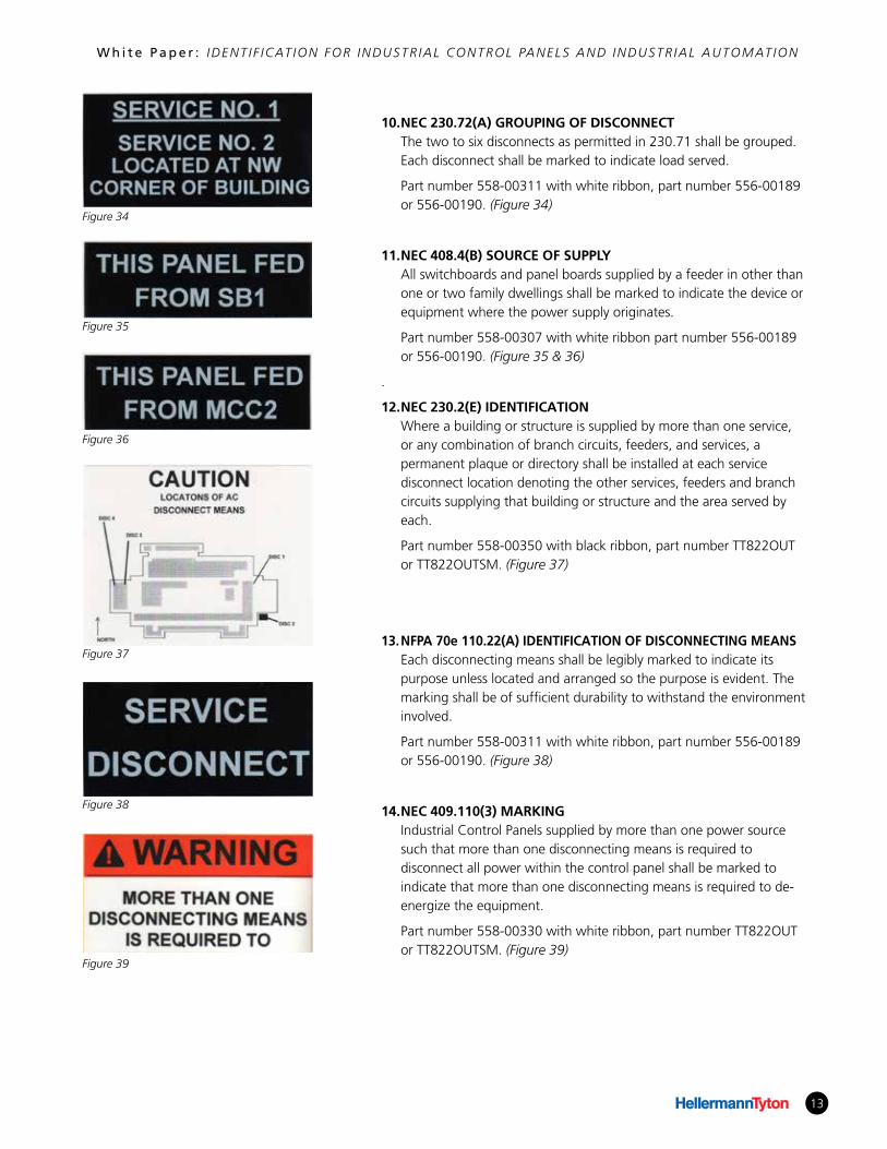
12. NEC 230.2(E) IDENTIFICATION Where a building or structure is supplied by more than one service, or any combination of branch circuits, feeders, and services, a permanent plaque or directory shall be installed at each service disconnect location denoting the other services, feeders and branch circuits supplying that building or structure and the area served by each.
Part number 558-00350 with black ribbon, part number TT822OUT or TT822OUTSM. (Figure 37)
13. NFPA 70e 110.22(A) IDENTIFICATION OF DISCONNECTING MEANS Each disconnecting means shall be legibly marked to indicate its purpose unless located and arranged so the purpose is evident. The marking shall be of sufficient durability to withstand the environment involved.
Part number 558-00311 with white ribbon, part number 556-00189 or 556-00190. (Figure 38)
14. NEC 409.110(3) MARKING Industrial Control Panels supplied by more than one power source such that more than one disconnecting means is required to disconnect all power within the control panel shall be marked to indicate that more than one disconnecting means is required to de-energize the equipment.
Part number 558-00330 with white ribbon, part number TT822OUT or TT822OUTSM. (Figure 39)
Figure 34
Figure 35
Figure 36
Figure 37
Figure 38
Figure 39
14
W h i t e P a p e r : IDENT I F ICAT ION FOR INDUSTR IAL CONTROL PANELS AND INDUSTR IAL AUTOMAT ION
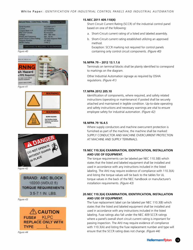
15. NEC 2011 409.110(4) Short Circuit Current Rating (SCCR) of the industrial control panel based on one of the following:
a. Short-Circuit current rating of a listed and labeled assembly.
b. Short-Circuit current rating established utilizing an approved method. Exception: SCCR marking not required for control panels containing only control circuit components. (Figure 40)
16. NFPA 79 – 2012 13.1.1.6 Terminals on terminal blocks shall be plainly identified to correspond to markings on the diagram.
Other Industrial Automation signage as required by OSHA regulations. (Figure 41)
17. NFPA 2012 205.10 Identification of components, where required, and safety related instructions (operating or maintenance) if posted shall be securely attached and maintained in legible condition. Up-to-date operating and safety instructions and necessary warnings are vital to ensure employee safety for industrial automation. (Figure 42)
18. NFPA 79 16.4.5 Where supply conductors and machine overcurrent protection is furnished as part of the machine, the machine shall be marked: SUPPLY CONDUCTOR AND MACHINE OVERCURRENT PROTECTION AT MACHINE AND SUPPLY TERMINALS.
19. NEC 110.3(A) EXAMINATION, IDENTIFICATION, INSTALLATION AND USE OF EQUIPMENT. The torque requirements can be labeled per NEC 110.3(B) which states that the listed and labeled equipment shall be installed and used in accordance with any instructions included in the listed labeling. The AHJ may require evidence of compliance with 110.3(A) and listing the torque values will tie back to the tables for UL torque values in the back of the NEC handbook or manufacturer’s installation requirements. (Figure 43)
20. NEC 110.3(A) EXAMINATION, IDENTIFICATION, INSTALLATION AND USE OF EQUIPMENT. The fuse replacement label can be labeled per NEC 110.3(B) which states that the listed and labeled equipment shall be installed and used in accordance with any instructions included in the listed labeling. Fuse ratings also fall under the NEC 409 SCCR ratings where a panel’s overall short circuit current rating is important for passing inspection. The AHJ may require evidence of compliance with 110.3(A) and listing the fuse replacement number and type will ensure that the SCCR rating does not change. (Figure 44)
Figure 40
Figure 41
Figure 42
Figure 43
Figure 44
15
W h i t e P a p e r : IDENT I F ICAT ION FOR INDUSTR IAL CONTROL PANELS AND INDUSTR IAL AUTOMAT ION
PART 4 – MAINTENANCE
4.1 WARNING LABELS AND SIGNS
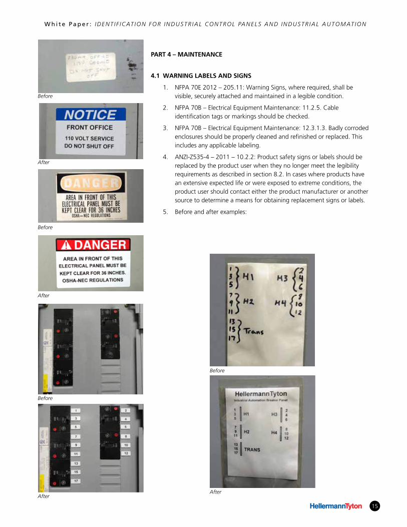
1. NFPA 70E 2012 – 205.11: Warning Signs, where required, shall be visible, securely attached and maintained in a legible condition.
2. NFPA 70B – Electrical Equipment Maintenance: 11.2.5. Cable identification tags or markings should be checked.
3. NFPA 70B – Electrical Equipment Maintenance: 12.3.1.3. Badly corroded enclosures should be properly cleaned and refinished or replaced. This includes any applicable labeling.
4. ANZI-Z535-4 – 2011 – 10.2.2: Product safety signs or labels should be replaced by the product user when they no longer meet the legibility requirements as described in section 8.2. In cases where products have an extensive expected life or were exposed to extreme conditions, the product user should contact either the product manufacturer or another source to determine a means for obtaining replacement signs or labels.
5. Before and after examples:
Before
Before
Before
Before
After
After
AfterAfter
16
W h i t e P a p e r : IDENT I F ICAT ION FOR INDUSTR IAL CONTROL PANELS AND INDUSTR IAL AUTOMAT ION
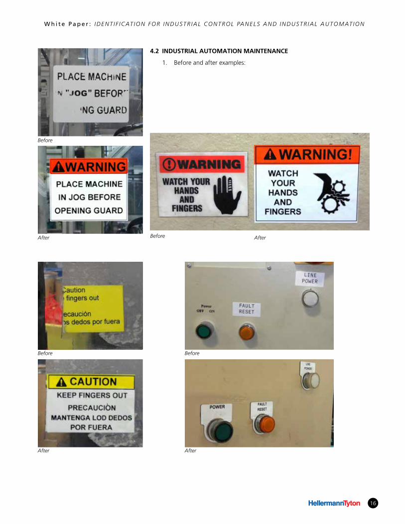
4.2 INDUSTRIAL AUTOMATION MAINTENANCE
1. Before and after examples:
Before
Before
Before Before
After
After After
After
17
W h i t e P a p e r : IDENT I F ICAT ION FOR INDUSTR IAL CONTROL PANELS AND INDUSTR IAL AUTOMAT ION
17© HellermannTyton Corporation
HellermannTyton North AmericanCorporate Headquarters7930 N. Faulkner Rd, PO Box 245017Milwaukee, WI 53224-9517Phone: (800) 822-4352Fax: (414) 355-7341email: [email protected], ISO 9001, and ISO 14001 Certified
About HellermannTytonHellermannTyton is a global manufacturer of identification, cable management
and connectivity solutions for the commercial data, telecommunications,
electrical, and industrial markets. HellermannTyton offers an integrated approach
to design, operation, and delivery to optimize service and solutions for local and
global customers. The company’s engineered solutions and innovative products
are designed and constructed to meet the strictest quality standards while
delivering reliable implementation at the lowest cost.
For more information, call HellermannTyton at 800.537.1512 or visit
www.hellermann.tyton.com for published details.
This information contained in the document represents the current view of HellermannTyton with respect to the subject matter contained herein as of the date of the publication. HellermannTyton makes no commitment to keep the information presented up to date and the facts in this document are subject to change without notice. As HellermannTyton must respond to the changing market conditions, HellermannTyton cannot guarantee the accuracy of any information presented after the date of the issuance. This document is presented for informational purposes only.
All rights reserved. No part of these pages, either text or image may be used for any purpose other than personal use. Therefore, reproduction, modification, storage in a retrieval system or retransmission, in any form or by any means, electronic, mechanical or otherwise, for reasons other than personal use, is strictly prohibited without prior written permission.
Copyright 2016, All rights reserved. May not be reproduced without the consent of HellermannTyton.
AuthorTodd FriesMarketing Manager, Identification Systems
Todd Fries is the Marketing Manager of Identification Systems with HellermannTyton, a
recognized manufacturer and supplier of products and solutions which help connect, protect,
manage and identify wire and cable components. HellermannTyton is a global manufacturer
located in 34 countries with North American headquarters in Milwaukee, Wisconsin.