icold small dams sept 2011
TRANSCRIPT
8/12/2019 ICOLD Small Dams Sept 2011
http://slidepdf.com/reader/full/icold-small-dams-sept-2011 1/149
1
SMALL DAMSDesign, Survei l lance and Rehab i l i tat ion
PETITS BARRAGESConceptio n , Survei llance etRéhab il i tat ion
2011
BULLETIN No ...

8/12/2019 ICOLD Small Dams Sept 2011
http://slidepdf.com/reader/full/icold-small-dams-sept-2011 2/149
2
AD HOC COMMITTEE ON SMALL DAMS(2005-2010)
Chairman/PrésidentBrazil J.F.A. SILVEIRA
Members/MembresBulgaria C. B. ABADJIEVCanada G. VERZENI
P. MITCHELMORE (1)China J. SHENGCzech Republic J. POLACEKFrance P. ROYETIndia G. N. MATHUR(2)
V.K.KANJLIA
Iran J. ATTARI (3) A. SOROUSH (4)
Japan Y. MATSUURALebanon A. MEOUCHY (5)Morroco A. LABRAIMI (6)Nigeria OLA, SAMUELPakistan I. B. SHAIKH (7)Russia S. A. SHMANENKOVSouth Africa D. BADENHORSTSpainSweden
F.J.S.CABEZAS (8)Y. HELMFRID (9)
The United States D. MILLER
United Kingdom A. HUGHES Australia (corresp. member) P. CUMMINS
(1) Member since May 2009(2) Member until December 2008(3) Member until June 2007(4) Member since Jan 2008(5) Member since June 2008(6) Member since June 2006(7) Member since June 2006(8) Member since June 2008(9) Member since June 2010

8/12/2019 ICOLD Small Dams Sept 2011
http://slidepdf.com/reader/full/icold-small-dams-sept-2011 3/149
3
FOREWORD
The ICOLD – International Committee on Large Dams decided to prepare a bulletin on small
dams in consideration to the great number of this type of dams, that represents generally morethan 90% of the total number of dams.
There are clear evidences of the construction of the first small dams about 5000 years ago inJordan, about 4600 years ago in Egypt and Baluchistan, and from 3250 to 3500 in Turkey,Yemen and Greece. These data and other with a “Historical Review on Ancient Dams” arepresented at the ICOLD Bulletin No 143, to be published in 2011 by ICOLD.
This bulletin was prepared as a guide for small dam owners, engineering, Governmentagencies, developers and contractors who are in charge with the design, construction,operation, maintenance and safety of small dams. This bulletin was developed mainly to theembankment dams which represent the very large majority of small dam. It is howeverimportant to point out that laws and regulations vary with different countries, and may even be
stricter than the guidelines in this bulletin.
In this bulletin “Small Dams” are defined as having the following characteristics:
o 2,5 m < H < 15 m and V H .2 < 200o H is height in meters above river bed level to maximum crest levelo V is storage volume in million m3 at maximum operating level = full supply level.
Design criteria and typical features for small dams are generally different from those for highdams, because the construction methods focus upon economy. So the risk may increase andcorresponding accidents may cause significant victims. The basic principle of design is toproduce a satisfactory functional structure at a minimum total cost. At the “Features of theDesign of Small Embankment Dams” are presented the important contributions from China,
United States, France, South Africa, Australia, Czech Republic and Japan, related to therecommended embankment slopes for small dams based on the experience with theconstruction of a large number of those small structures.“Guidelines on Surveillance of Small Dams” presents the main recommendations in order toassure that the dams will behave appropriately and with a minimum cost. The construction of adam can involve a significant investment and dam owners need to ensure that their money iswell spent and that their dam becomes an asset.
Ageing of embankment dams, updating of design standards and criteria and the deteriorationof conditions affecting the safety of small dams are analyzed in detail at the “RehabilitationPractices for Small Dams”, emphasizing the main remedial measures related to embankmentdams.
At the “Emergency Action Plan (EAP)” are emphasized the main points concerned theapplication of such plan to minimize the consequences of a dam failure or malfunction,regarding the population living downstream, presenting some recommendation about how todevelop an EAP, evaluating the possible dam risks and the management of the dam safety.
At the “Legislation & Decommissioning” chapter are pointed out the dam safety and securityof people, property and environment downstream of dams and the important responsibility ofthe Government, who must legislate and enforce the rules through administrative agencies,departments and offices.

8/12/2019 ICOLD Small Dams Sept 2011
http://slidepdf.com/reader/full/icold-small-dams-sept-2011 4/149
4
It is important to be in charge with the performance of our large dams, but also with theperformance of the small one, as a consequence of the large number of these dams. We hadthe opportunity to learn that in most countries more than 90 % are small dams, which failureconsequences can be catastrophic to the downstream residents, infrastructure and theenvironment.
JOÃO FRANCISCO A. SILVEIRAChairman of the Ad Hoc Committee on Small Dams

8/12/2019 ICOLD Small Dams Sept 2011
http://slidepdf.com/reader/full/icold-small-dams-sept-2011 5/149
5
ACKNOWLEDGEMENT
The Ad Hoc Committee on Small Dams and the ICOLD Executive gratefully acknowledge,initially, the suggestion of Mr. C.V.J. Varma from India, to create this committee, during the72nd Annual ICOLD Meeting, in Seoul, 2004, when he was the ICOLD President, and also toMr. C.B. Viotti from Brasil, the next ICOLD President, for its creation at the 73 rd Annual ICOLDMeeting, in Tehran, 2005.
In the elaboration of the “Historical Review on Ancient Dams”, that is just the Volume I ofour ICOLD Committee, we received the special collaboration from the following members: Mr.Mathur, from India, Mr. Matsuura, from Japan, Mrs. Miller, from The United States, Mr.Polacek, from Czech Republic, Mr. Royet, from France, Mr. Sheng, from China, Mr. Attari,from Iran, and Mr. Yong-Nam, from Korea.
In the elaboration of the “Small Dams – Design, Surveillance and Rehabilitation”, that is theVolume II of our ICOLD Committee, we received collaborations from all our members, butsome very important one from Mr. Royet, from France, Mr. Badenhorst, from South Africa, Mr.
Abadjiev, from Bulgaria, Mr. Matsuura, from Japan, Mr. Polacek, from Czech Republic and MrSánchez, from Spain.
8/12/2019 ICOLD Small Dams Sept 2011
http://slidepdf.com/reader/full/icold-small-dams-sept-2011 6/149
6
TABLE OF CONTENTS
-FOREWORD 03
- ACKNOWLEDGEMENT 05
1SMALL DAMS DEFINITON AND
CLASSIFICATION13
2
TYPES OF SMALL DAMS
18
3 SAFETY OF SMALL DAMS 31
4 LEGISLATION & DECOMMISSIONING 40
5 FEATURES OF THE DESIGN OF SMALLEMBANKMENT DAMS
49
6GUIDELINES ON SURVEILLANCE OF
SMALL DAMS93
7 REHABILITATION PRACTICES FORSMALL DAMS
114
8 EMERGENCY ACTION PLAN FORSMALL DAMS
140
TOTAL149
8/12/2019 ICOLD Small Dams Sept 2011
http://slidepdf.com/reader/full/icold-small-dams-sept-2011 7/149
7
TABLE OF CONTENTS
FOREWORD
ACKNOWLEDGEMENT
SUMMARY
1. SMALL DAMS DEFINITION AND CLASSIFICATION
1.1 Classification
1.2 Definition of small dams
1.3 References
2. TYPES OF SMALL DAMS
2.1 Introduction
2.2 Homogeneous earthfill dams
2.3 Zoned earthfill dams
2.3.1 Central clay core dams
2.3.2 Sloping core dams
2.3.3 Zhaogushe dams
2.4 Stone masonry dams
2.5 Concrete gravity dams
2.6 Concrete buttress dams
2.7 Gabion dams
2.8 Inflatable dam type
2.9 References
3. SAFETY OF SMALL DAMS
3.1 Introduction
3.2 Conditions affecting the safety
3.3 Causes of dam failures
3.3.1 General

8/12/2019 ICOLD Small Dams Sept 2011
http://slidepdf.com/reader/full/icold-small-dams-sept-2011 8/149
8
3.3.2 Overtopping caused by flood
3.3.3 Internal erosion
3.3.4 Slope instability
3.4 References
4. LEGISLATION & DECOMMISSIONING
4.1 Introduction
4.2 The regulation
4.3 The supervising authority
4.4 The owner
4.5 Decommissioning
4.6 Conclusion
4.7 References
5. FEATURES OF THE DESIGN OF SMALL EMBANKMENT DAMS
5.1 Introduction
5.2 Design floods
5.3 Homogenous and zoned embankments design
5.3.1 Homogenous type
5.3.2 Zoned embankment type
5.4 Freeboard
5.4.1 Definitions of freeboard
5.4.2 Freeboard design considerations
5.4.3 Freeboard design for wave run-up and wind setup
5.4.4 First approximations for freeboard requirements
5.4.5 Camber
5.5 Soil compaction
5.5.1 Compaction standards
5.5.2 Water content variation and effect on geomechanical properties
5.5.3 Layer thicknesses
5.5.4 Quality control during compaction

8/12/2019 ICOLD Small Dams Sept 2011
http://slidepdf.com/reader/full/icold-small-dams-sept-2011 9/149
9
5.5.5 Compaction in confined areas
5.5.6 Testing of the pipe
5.5.7 Compaction of filters
5.6 Dam foundation treatment
5.6.1 Foundation watertightness
5.6.2 Foundation drainage
5.7 Drainage system for earthfill dams
5.7.1 Seepage control measures
5.7.1.1 Measures for pervious ground
5.7.1.2 Blanket grouting method
5.7.1.3 Artificial blanket
5.7.1.4 Practical considerations
5.7.1.5 Filter material criteria
5.7.1.6 Piping prevention criteria
5.7.1.7 Criteria regarding permeability
5.7.1.8 Uniform criteria
5.7.1.9 Criteria for the inherent stability of a filter
5.7.1.10 Cohesion clay criteria
5.7.1.11 Criteria regarding dispersive clay
5.7.1.12 Organic material criteria
5.7.1.13 Criteria and practice regarding synthetic materials
5.8 Slope stability
5.8.1 Introduction
5.8.2 Critical cases for analysis
5.8.3 Limiting equilibrium methods
5.8.4 Minimum safety factors against slipe circle failures
5.9 Surface drainage
5.9.1 Principles
5.9.2 Possible mechanical solution of the surface dewatering
8/12/2019 ICOLD Small Dams Sept 2011
http://slidepdf.com/reader/full/icold-small-dams-sept-2011 10/149
10
5.10 Slope protection
5.10.1 Upstream slope protection
5.10.2 Selecting the type of upstream protection
5.10.3 Dowstream slope protection with grass
5.10.4 Dowstream slope protection with gravel
5.10.5 Protection from seepage piping
5.11 Crest design
5.11.1 Width
5.11.2 Drainage
5.11.3 Allowance for settlement
5.11.4 Surfacing
5.11.5 Traffic safety requirements
5.12 Construction techniques for the foundation and the fill
5.13 References
6. GUIDELINES ON SURVEILLANCE OF SMALL DAMS
6.1 Introduction
6.2 Safety surveillance
6.3 Surveillance practices
6.3.1 Inspection procedures
6.3.2 Dam inspection and performance evaluation
6.3.3 Inspections after earthquakes
6.4 Monitoring system
6.4.1 Monitoring instruments for small dams
6.4.2 Guidelines on dam monitoring
6.4.3 Data analysis and reporting
6.5 References
7. REHABILITATION PRACTICES FOR SMALL DAMS
7.1 Introduction
7.2 Techniques for improving spillway safety

8/12/2019 ICOLD Small Dams Sept 2011
http://slidepdf.com/reader/full/icold-small-dams-sept-2011 11/149
11
7.2.1 Introduction
7.2.2 Spillway capacity
7.2.3 Backward erosion control
7.2.4 Spillway chute or spillway return channel alignment
7.2.5 Deformation of spillway structures provided over embankments
7.2.6 Erosion of the abutment wall between the embankment and the spillway
7.2.7 Gabions used as sill in by-pass channels
7.3 Techniques for improving embankment safety
7.3.1 Techniques to overcome flood handling problem
7.3.1.1 Parapet wall
7.3.1.2 Raise embankment crest
7.3.1.3 Protection of embankment from erosion during overtopping
7.3.2 Slope stability
7.3.3 Piping control measures
7.3.4 Seepage control measures
7.3.4.1 Seepage barriers and cutoff systems
7.3.4.2 Seepage interception and exit control with filters and drains
7.3.5 Slope protection measures
7.3.5.1 Vegetal protection
7.3.5.2 Rip-rap or gravel protection of the downstream face of the embankment
7.3.6 Techniques for the rehabilitation of bottom outlets on embankment dams
7.3.6.1 Renovation of conduits
7.3.6.2 Filter around conduits
7.3.6.3 Pipe abandonment
7.3.7 Techniques for rehabilitation of hydromechanical components
7.3.8 Restoring reservoir capacity in case of siltation
7.4 References
8. GUIDELINES ON EMERGENCY ACTION PLAN (EAP)
8.1 Introduction

8/12/2019 ICOLD Small Dams Sept 2011
http://slidepdf.com/reader/full/icold-small-dams-sept-2011 12/149
12
8.2 How to develop an emergency action plan
8.3 Evaluation of possible risks
8.3.1 Overtopping during extremes floods
8.3.2 Piping and internal erosion
8.3.3 Earthquake
8.3.4 Failure of upstream dams
8.3.5 Failure of slopes in the reservoir
8.3.6 Sabotage
8.4 Small dam risk management
8.5 Dam site access during severe storms
8.6 Dam break and inundation map
8.7 Permanent file for emergency purposes
8.8 Emergency exercising and updating
8.9 References
8/12/2019 ICOLD Small Dams Sept 2011
http://slidepdf.com/reader/full/icold-small-dams-sept-2011 13/149
13
1. SMALL DAMS DEFINITION AND CLASSIFICATION
The term “small dams” has various meanings and perceptions in the world. For some a20m high dam will be the largest of the small dams category, while others see it as thesmallest large dam. Dams are being defined as having a safety risk when the dam height ishigher than 2m in America and 5m in South Africa, and having a storage capacity of a 30 000m3 and 50 000 m3 respectively.
Furthermore, the concept of consequential damages and loss of life for the case of adam failure is widely used for classification of all dams into hazard classes, normally as low,medium and high. The consequential damages are determined for the inundated area causedby a dam break flooding event. Dam storage volume, depth of water at the dam wall and timeof the development of the breach are the most important parameters for the determination ofthe dam break flood.
Large dams are being defined by ICOLD as any dam with:
maximum height (H), measured from deepest foundation level to highest structurecrest level, more than 15m, or
10m < H < 15m, and the following conditions:• dam length more than 500 m,• reservoir storage capacity more than 3 million m3,• flood discharge more than 2 000 m3/s, and• unusual characteristics in dam type or foundation.• suggestions and references
1.1 CLASSIFICATION
The French Committee on Dams and Reservoirs has developed a classification systemfor dams [1] with two of the main parameters usually used in the determination of a dam break
flood, height and storage volume of dam. These two parameters are combined as V H .2 with H = maximum height of dam wall in meters, measured from river bed level and V =storage volume of reservoir at full supply level in million cubic meters. It has no particularscientific significance, but it is an applicable deterministic “factor” for weighing potential risk ofdamages and loss of lives in the dam break flooding area in event of a dam breach. Thiscombined parameter is used for the classification into low medium and high classes and for
the identification of design criteria applicable to the classes for various design componentsmentioned in this bulletin.
The relationship on a log of storage volume to normal dam height scale and some valuesare being shown on Figure 1.1.

8/12/2019 ICOLD Small Dams Sept 2011
http://slidepdf.com/reader/full/icold-small-dams-sept-2011 14/149
14
Fig. 1.1 – Relationship V H .2 for small dams
Using this relationship and related associated weighted breakdowns for risk to loss oflives, economy, environmental and social “damages” this small dams bulletin uses thefollowing Potential Hazard Classification (PHC) system as shown in Table 1.1:
Table 1.1 – Potential Hazard Classification (PHC).
Component Potential Hazard Classification (PHC)Low – (I) Medium - (II) High - (III)
V H .2 parameter V H .2 <2020 < V H .2
<200V H .2
≥ 200
Life Safety Risk(number of lives)
~ 0 < 10 ≥ 10
Economic Risk low moderate high or extremeEnvironment Risk low or moderate high extremeSocial Disruption low (rural area) regional national
The PHC is related to the highest criterion. For example, a dam with V H .2 < 200 but
with more than 10 people exposed to risk should be classified as PIC = III.
However, in the bulletin, only the V H .2
parameter is used. The classification in termsof the parameter is shown in Figure 1.2. A few Brazilian, Spain and South African dams areindicated on the figure.

8/12/2019 ICOLD Small Dams Sept 2011
http://slidepdf.com/reader/full/icold-small-dams-sept-2011 15/149
15
Fig. 1.2 – Relationship V H .2 with the indication of the PHC – Potential Hazard Classification(Examples of small dams in Brazil, Spain and South Africa shown)
1.2 DEFINITION OF SMALL DAMS
For this bulletin “Small Dams” are defined as having the following characteristics:
o 2,5 m < H < 15 m and V H .2 < 200 (*)o H is height in meters above river bed level to maximum crest levelo V is storage volume in million m3 at Maximum Operating Level = Full Supply
Level in most cases.(*) Minimum dam height can be changed to 2 or 3 m in the case of dams in residential or verypopulated areas.
Dams with 5 < H < 15 m and V > 3 hm 3 (million cubic meters) are classified as largedams according the ICOLD.
For flood retention dams holding no water the storage volume at crest of spillway level
(design storage volume) should be used.The classification of small dams as well as large dams is shown on Figure 1.3.

8/12/2019 ICOLD Small Dams Sept 2011
http://slidepdf.com/reader/full/icold-small-dams-sept-2011 16/149
16
Fig. 1.3 – Classification of small and large dams
From the right hand side of Figure 1.3 it is clear that the definition of large dams isslightly adapted. The red line represents the original definition of large dams.
The reason why the river bed level must be used is that the dam break flood empiricalformula uses the water depth influencing the dam break water wave causing the damagedownstream as the parameter. If a 10m high dam is founded on a foundation 8m deep, the
18m height of the structure cannot be used to classify the dam as a large dam, because the8m below river bed level has no influence on the dam break flood, as illustrate in Figure 1.4.
Figure 1.4 – Illustration about Small Dam Height

8/12/2019 ICOLD Small Dams Sept 2011
http://slidepdf.com/reader/full/icold-small-dams-sept-2011 17/149
17
1.3 REFERENCES
[1] French Committe on Dams and Reservoirs (1997) Guidelines for Design, Construction,and Monitoring. Coordinator Gerard Degoutte. ISBN 2-85362-448.
[2] ICOLD (1983) – Deterioration of Dams and Reservoir, Report prepared by a team ofPortuguese engineers of the “Laboratory of a Civil Engineering, LNEC, Lisboa;
[3] ICOLD (1986) – Soil-Cement for Embankment Dams / Sol-Ciment Pour les Barrages enRemblai, Bulletin 54 ;
[4] ICOLD (1988) – Dam Monitoring General Considerations / Auscultation des BarragesConsidérations Générales, Bulletin 60.
[5] ICOLD (1988) – Inspection of Dams Following Earthquake – Guidelines / Inspection desBarrages Après Séisme - Recommandations, Bulletin 62.
[6] ICOLD (1990) – Dispersive Soils in Embankment Dams / Sols Dispersifs Dans lesBarrages en Remblai, Bulletin 77.
[7] ICOLD (1992) – Improvement of Existing Dam Monitoring, Recommendations and CaseHistories / Amelioration de L’Auscultation des Barrages, Recommandations et
Exemples, Bulletin 87.
[8] ICOLD (1993) – Embankment Dams Upstream Slope Protection / Barrages en RemblaiProtection du Talus Amont, Bulletin 91.
[9] ICOLD (1994) – Ageing of Dams and Appurtenant Works / Vieillissement des Barrages
et des Ouvrages Annexes, Bulletin 93.
[10] ICOLD (1997) – Dams Less Than Thirty Meters High; Barrages de Moins de 30 m deHauteur, Bulletin 109.
[11] ICOLD (2000) – Monitoring of Dams and Their Foundation / Auscultation des Barrageset des Leurs Fondations, Bulletin 78.
[12] ICOLD (2005) – Risk Assessment in Dam Safety Management / Évaluation du Risquedans la Gestion de la Sécurité du Barrage, Bulletin 130.
[13] ICOLD (2007) – Dam Surveillance / La Surveillance des Barrages, TCDS Draft Bulletin
No 1 (Rev. 0 - Fev 2007).
[14] CSN 752410 (1997) – "Small Water Reservoirs" , Czech Republic Standard CSN 752410.

8/12/2019 ICOLD Small Dams Sept 2011
http://slidepdf.com/reader/full/icold-small-dams-sept-2011 18/149
18
2. TYPES OF SMALL DAMS
2.1 INTRODUCTION
Small dams may be grouped into different categories, such as: Use Hydraulic Design Type of Materials
In this bulletin it will be adopted that dam types are defined in accordance with thematerial used in their construction, as illustrated in the following examples. Most of the typesare the traditional, while others are the new ones, like the inflatable dam using a specialrubber.
2.2 HOMOGENEOUS EARTHFILL DAMS
Earthfill dams are the most common type of dam, principally because their constructioninvolves the use of materials from the required excavations and the use of locally availablenatural materials requiring a minimum of processing. Homogeneous dams are mostly adoptedwhere cohesive soils are found abundant. They are also preferable for gravelly cohesive soils(residual soils) as well as loess. However, such dams have a flatter slope, consequently, agreater volume of embankment, as illustrated bellow with some small dams built in China [1]and USA [2].
Fig. 2.1 – Hongshiyan homogeneous dam, China [1].
Fig. 2.2 – Crane Prairie Dam (1939 - 40), USA [2].
1 Rip-rap2 Silty clay3 Grass sod
8/12/2019 ICOLD Small Dams Sept 2011
http://slidepdf.com/reader/full/icold-small-dams-sept-2011 19/149
19
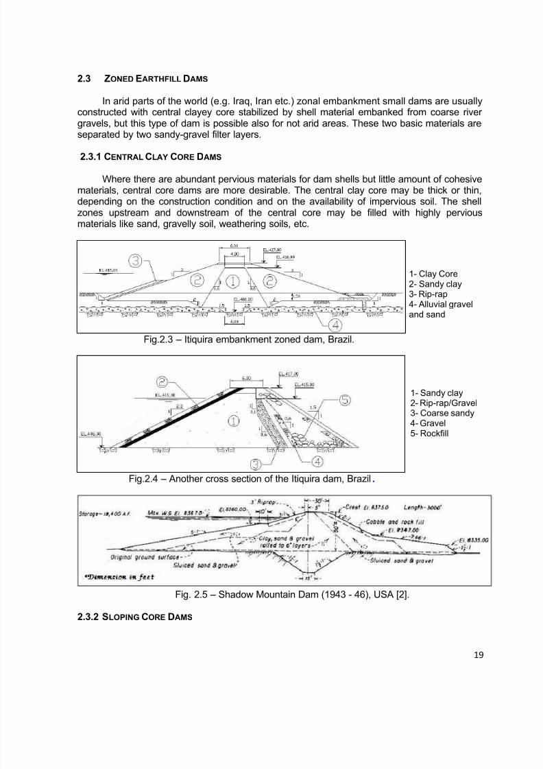
2.3 ZONED EARTHFILL DAMS
In arid parts of the world (e.g. Iraq, Iran etc.) zonal embankment small dams are usuallyconstructed with central clayey core stabilized by shell material embanked from coarse rivergravels, but this type of dam is possible also for not arid areas. These two basic materials are
separated by two sandy-gravel filter layers.
2.3.1 CENTRAL CLAY CORE DAMS
Where there are abundant pervious materials for dam shells but little amount of cohesivematerials, central core dams are more desirable. The central clay core may be thick or thin,depending on the construction condition and on the availability of impervious soil. The shellzones upstream and downstream of the central core may be filled with highly perviousmaterials like sand, gravelly soil, weathering soils, etc.
Fig.2.3 – Itiquira embankment zoned dam, Brazil.
Fig.2.4 – Another cross section of the Itiquira dam, Brazil.
Fig. 2.5 – Shadow Mountain Dam (1943 - 46), USA [2].
2.3.2 SLOPING CORE DAMS
1- Clay Core2- Sandy clay3- Rip-rap4- Alluvial graveland sand
1- Sandy clay
2- Rip-rap/Gravel3- Coarse sandy4- Gravel5- Rockfill
8/12/2019 ICOLD Small Dams Sept 2011
http://slidepdf.com/reader/full/icold-small-dams-sept-2011 20/149
20
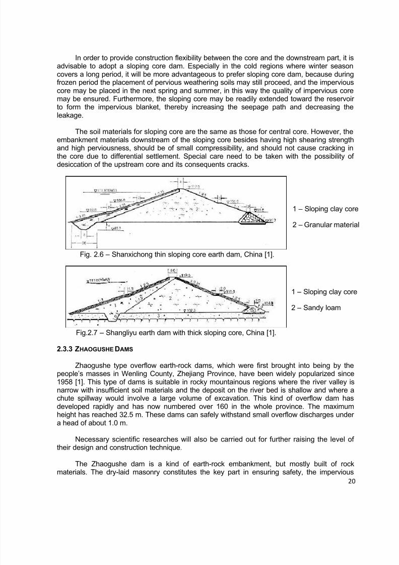
In order to provide construction flexibility between the core and the downstream part, it isadvisable to adopt a sloping core dam. Especially in the cold regions where winter seasoncovers a long period, it will be more advantageous to prefer sloping core dam, because duringfrozen period the placement of pervious weathering soils may still proceed, and the imperviouscore may be placed in the next spring and summer, in this way the quality of impervious core
may be ensured. Furthermore, the sloping core may be readily extended toward the reservoirto form the impervious blanket, thereby increasing the seepage path and decreasing theleakage.
The soil materials for sloping core are the same as those for central core. However, theembankment materials downstream of the sloping core besides having high shearing strengthand high perviousness, should be of small compressibility, and should not cause cracking inthe core due to differential settlement. Special care need to be taken with the possibility ofdesiccation of the upstream core and its consequents cracks.
Fig. 2.6 – Shanxichong thin sloping core earth dam, China [1].
Fig.2.7 – Shangliyu earth dam with thick sloping core, China [1].
2.3.3 ZHAOGUSHE DAMS
Zhaogushe type overflow earth-rock dams, which were first brought into being by thepeople’s masses in Wenling County, Zhejiang Province, have been widely popularized since1958 [1]. This type of dams is suitable in rocky mountainous regions where the river valley isnarrow with insufficient soil materials and the deposit on the river bed is shallow and where a
chute spillway would involve a large volume of excavation. This kind of overflow dam hasdeveloped rapidly and has now numbered over 160 in the whole province. The maximumheight has reached 32.5 m. These dams can safely withstand small overflow discharges undera head of about 1.0 m.
Necessary scientific researches will also be carried out for further raising the level oftheir design and construction technique.
The Zhaogushe dam is a kind of earth-rock embankment, but mostly built of rockmaterials. The dry-laid masonry constitutes the key part in ensuring safety, the impervious
1 – Sloping clay core
2 – Granular material
1 – Sloping clay core
2 – Sandy loam

8/12/2019 ICOLD Small Dams Sept 2011
http://slidepdf.com/reader/full/icold-small-dams-sept-2011 21/149
21
sloping core guarantees water impoundment of the dam, the rockfill improves the stability ofthe masonry, and the filter layers ensure effective and long term functioning of the clay core.The Zhaogushe dam has a cross section composed of five parts as shown in Fig. 2.8.
Fig. 2.8 – Cross section of Zhaogushe type overflow dam, China [1].
2.4 STONE MASONRY DAMS
Large pieces of stones have been used in the construction of dams since theconstruction of Sadd El Khafara dam, in Egypt, about 20km south-east Cairo, 4.600 years ago,one of the oldest dams ever registered. In this dam it is estimated that about 17 000 revetmentblocks on both outer faces, each weighing 300 kg, had been carefully placed and part of themstill exist until our days.
Ancient large stone masonry dams, however, are scarce, and most of the large stonemasonry dams in China were built more recently. All together, 1,000 stone masonry dams ofvarious types were completed from 1949 to 1977.
The reasons for the rapid development of stone masonry dams in China are many. In thefirst place, they favor the use of local materials in mountainous regions where rock materialsare available in greater quantity than soils. The volume of a masonry dam is smaller than thatof an earth dam. Masonry dams can save on timber, steel and cement. Moreover, the crest ofa stone masonry dam permits overflowing, thereby solution is rendered easier for river flowdiversion and passage of floods during construction.
Fig. 2.9 – Straw-raincoat dam, China [1].
1 – Dry-laid masonry
2 – Sloping clay core
3 – Rockfill
4 – Filters
5 – Rough interface
6 – Cutoff
7 – Rock foundation
1 – Dumped rockfill
2 – Earthfill clay
3 – Foundation of
sand and gravel

8/12/2019 ICOLD Small Dams Sept 2011
http://slidepdf.com/reader/full/icold-small-dams-sept-2011 22/149
22
2.5 CONCRETE GRAVITY DAMS
Concrete gravity dams are suitable for sites where there is a reasonable sound rockfoundation, although low structures may be founded on saprolite soils or alluvial foundations ifadequate cutoffs are provided. They are well suited for use as overflow spillway crests and are
often used as spillways for earthfill or rockfill dams or as overflow sections of diversion dams.Gravity dams may be either straight (Fig. 2.10) or curved in plan. The curved dam may offersome advantage in both cost and safety.
Fig. 2.10 – Lopyan Concrete Gravity dam, 11.60 m height, built in 2004 in Bulgaria

8/12/2019 ICOLD Small Dams Sept 2011
http://slidepdf.com/reader/full/icold-small-dams-sept-2011 23/149
23
Fig. 2.11 – Hlinky Concrete Gravity dam, height 11m, Czech Republic.
RCC DAMS
The term “roller compacted concrete” describes concrete used in the constructionprocess, which combines economical and rapid placing techniques of embankment materialwith those excellent mechanical properties of concrete, such as strength and durability. This
technique is best suited to multi-layer constructions with a high ratio of surface to thickness,that is to say, pavements and dams.
Today, roller compacted concrete dams are being discussed, designed, and constructedin many of the developed and developing countries throughout the world. Its use in arch damconstruction has increased mainly in China, South Africa and Brazil.
Interest in this type of dam has increased for several reasons, the most prominent beingeconomics and construction speed. In many countries the costs of conventional concretedams have increased significantly faster than corresponding costs for embankment dams. Butthe fact that concrete is such a good and long-lasting construction material, has stimulateddesigners to seek new ways of using it in dam construction. They succeeded with the adoption
of RCC technology.
Several Brazilian RCC dams either built, under construction or being designed werepreviously embankment dams. The change in dam types, owes much to the flexibility ofdesigners:
Usually taking into consideration the special requirements of the constructionmethodology, trying to avoid embedded parts;
Maintaining a close link with those responsible for the layout and projectplanning, thus adapting the design to the construction phases;
Taking advantage of the concrete characteristics.
8/12/2019 ICOLD Small Dams Sept 2011
http://slidepdf.com/reader/full/icold-small-dams-sept-2011 24/149
24
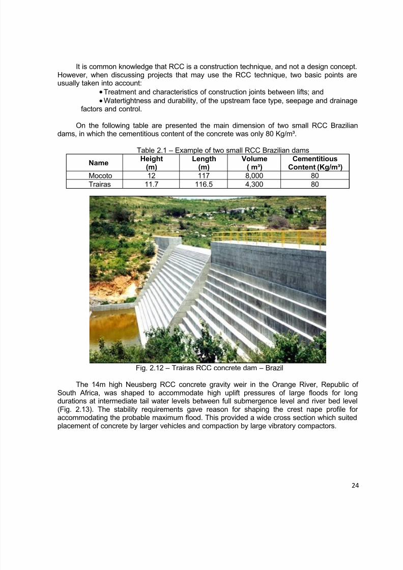
It is common knowledge that RCC is a construction technique, and not a design concept.However, when discussing projects that may use the RCC technique, two basic points areusually taken into account:
Treatment and characteristics of construction joints between lifts; and
Watertightness and durability, of the upstream face type, seepage and drainagefactors and control.
On the following table are presented the main dimension of two small RCC Braziliandams, in which the cementitious content of the concrete was only 80 Kg/m³.
Table 2.1 – Example of two small RCC Brazilian dams
NameHeight
(m)Length
(m)Volume
( m³)Cementitious
Content (Kg/m³)
Mocoto 12 117 8,000 80Trairas 11.7 116.5 4,300 80
Fig. 2.12 – Trairas RCC concrete dam – Brazil
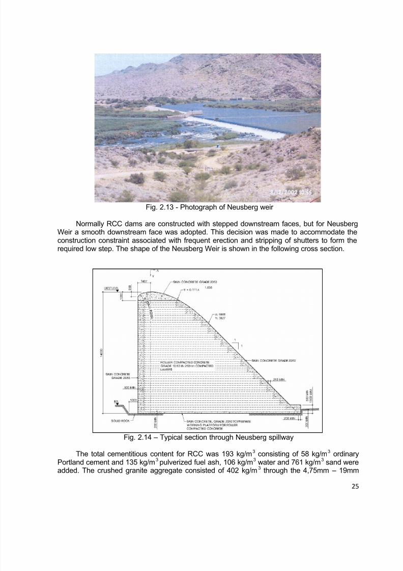
The 14m high Neusberg RCC concrete gravity weir in the Orange River, Republic ofSouth Africa, was shaped to accommodate high uplift pressures of large floods for long
durations at intermediate tail water levels between full submergence level and river bed level(Fig. 2.13). The stability requirements gave reason for shaping the crest nape profile foraccommodating the probable maximum flood. This provided a wide cross section which suitedplacement of concrete by larger vehicles and compaction by large vibratory compactors.
8/12/2019 ICOLD Small Dams Sept 2011
http://slidepdf.com/reader/full/icold-small-dams-sept-2011 25/149
25
Fig. 2.13 - Photograph of Neusberg weir
Normally RCC dams are constructed with stepped downstream faces, but for NeusbergWeir a smooth downstream face was adopted. This decision was made to accommodate theconstruction constraint associated with frequent erection and stripping of shutters to form therequired low step. The shape of the Neusberg Weir is shown in the following cross section.
Fig. 2.14 – Typical section through Neusberg spillway
The total cementitious content for RCC was 193 kg/m3 consisting of 58 kg/m3 ordinaryPortland cement and 135 kg/m3 pulverized fuel ash, 106 kg/m3 water and 761 kg/m3 sand wereadded. The crushed granite aggregate consisted of 402 kg/m3 through the 4,75mm – 19mm

8/12/2019 ICOLD Small Dams Sept 2011
http://slidepdf.com/reader/full/icold-small-dams-sept-2011 26/149
26
sieves, 598 kg/m3 through the 19 – 38mm sieves and 481 kg/m3 through the 38-53mm sizes.The 28 day 150mm cube strength of RCC was tested at 24.6 MPa. Drilled core resultsrevealed test strengths varying from 62.6 MPa to 30.9 MPa. The average density was 2443kg/m3, average tensile strength 3.3 MPa, Average Elasticity Modulus 36.2 GPa, an averagePoisson’s ratio 0.16 and the average permeability 6.7 x 10⁻⁷ cm/s.
2.6 CONCRETE BUTTRESS DAMS
Buttress dams are comprised of a flat deck and multiple arch structures or transversalconcrete buttresses as showed in Fig. 2.15, with only 7 m in height. They require about 60percent less concrete than solid gravity dams, but the increased formwork and reinforcementsteel require usually offset the savings in concrete. A number of buttress dams were built inthe 1930’s, in United States, when the ratio of labor costs to material costs was comparativelylow. The cost of this type of construction is usually not competitive with that of other types ofdams when labor costs are high.
Approximately 400 concrete buttress dams of all types were constructed in the UnitedStates. Of that number only 207 are in existence today, many of which are less than 9 m inheight.
Fig. 2.15 – Barra Buttress Concrete dam, Brazil.
2.7 GABION DAMS
First gabion retaining structures project was constructed in 1893 to retain the river banksof the River Reno, in Italy. The use of gabion for the construction of small dams is morerecent, but the Chinese employ this technique with bamboo mesh baskets probably for a longtime.

8/12/2019 ICOLD Small Dams Sept 2011
http://slidepdf.com/reader/full/icold-small-dams-sept-2011 27/149
27
The gabion dam as the gabion retaining structures employ generally wire mesh basketsfilled with rock at the downstream part of the dam to form a flexible, permeable, monolithicstructure similar to a gabion retaining wall. At the upstream part is compacted an earthfill asthe impervious element.
In Fig. 2.16 is presented an example of a small dam which have been built in Brazil inthe last years using gabion as construction material. It is a dam with 12 m height that ispresenting a good performance in the last ten years.
Fig. 2.16 – Gabion dam 12 m high - Brazil
2.8 INFLATABLE DAM T YPE
In recent years, inflatable dam technology has significantly advanced and has becomean economical solution for installing new and replacing old spillway crest gates up to 5.4 m.The hydraulic and environmental advantages of inflatable dams have also made them anattractive solution for constructing new and replacing old run of the river low-head gravitydams. In the United States, over 200 inflatable dams have been installed since 1980, and therate of their use on dam projects is increasing rapidly. Inflatable dam types have been installedin a wide variety of conditions, configurations and environments, according to [3]. The firstinflatable dam system known as the “Fabridam” was introduced in the mid 1950s.
In the following table is presented a summary of the main inflatable dam manufactures inthe world.
Table 2.2 - Summary of Inflatable Dam Worldwide [3]
8/12/2019 ICOLD Small Dams Sept 2011
http://slidepdf.com/reader/full/icold-small-dams-sept-2011 28/149
28
Country Year
IntroducedType of inflation
Number InstalledWorld (Area ft²) ¹
USA 1956 Air & Water -Japan 1968/1978 Air & Water or Air 1,900France 1972 Water 25
Austria 1977 Water 60Japan 1978 Air or Water > 700 (302,000)
Germany 1984 Air or Water 40USA 1988 Air 111
Australia 1997 Air or Water 3Czech Republic 1980 Water 20
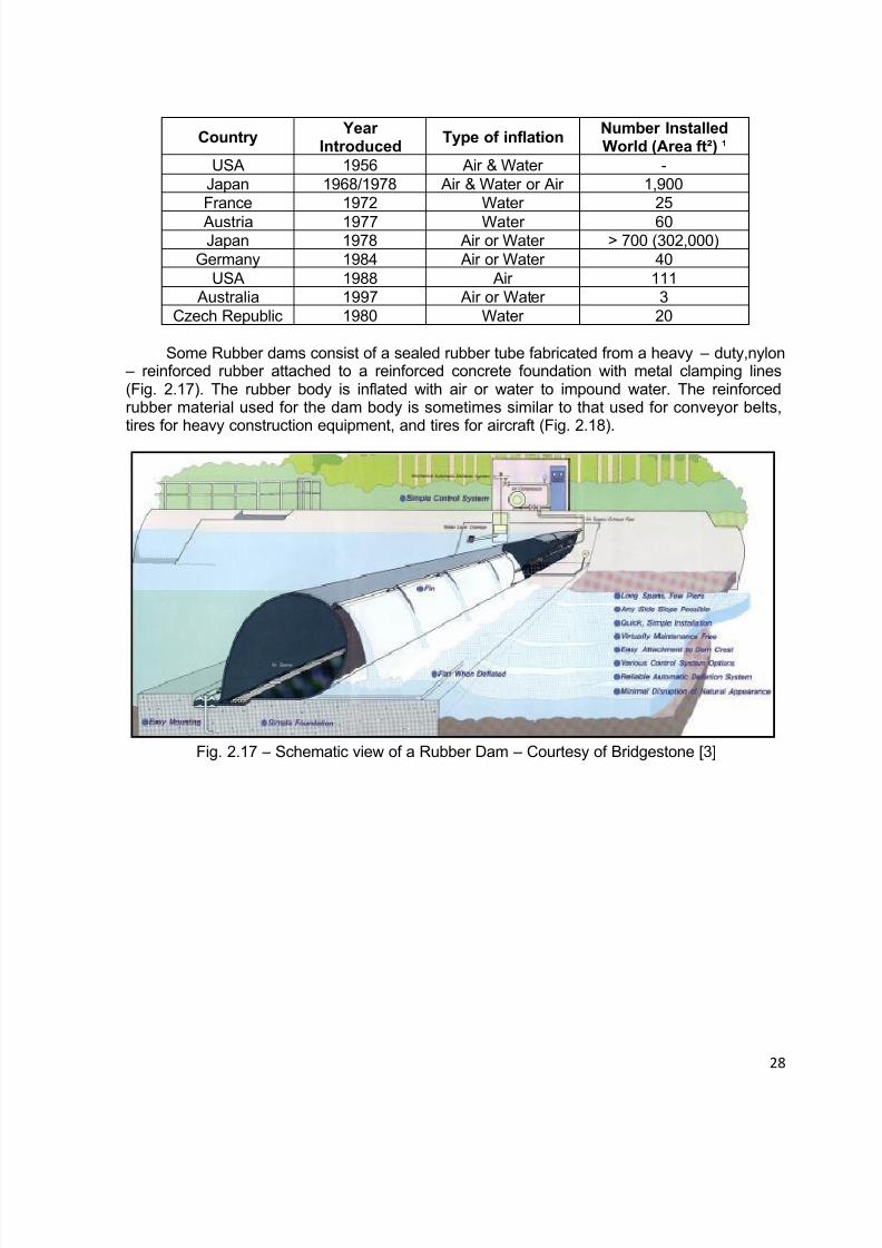
Some Rubber dams consist of a sealed rubber tube fabricated from a heavy – duty,nylon – reinforced rubber attached to a reinforced concrete foundation with metal clamping lines(Fig. 2.17). The rubber body is inflated with air or water to impound water. The reinforcedrubber material used for the dam body is sometimes similar to that used for conveyor belts,tires for heavy construction equipment, and tires for aircraft (Fig. 2.18).
Fig. 2.17 – Schematic view of a Rubber Dam – Courtesy of Bridgestone [3]

8/12/2019 ICOLD Small Dams Sept 2011
http://slidepdf.com/reader/full/icold-small-dams-sept-2011 29/149
29
Fig. 2.18 – Photo of an inflatable dam at Sunbury, PA, USA [3]
Fig. 18a – Inflatable Small Dam, Mlada Boleslav, Czech Republic
Some hydro gate system is similar to a hydraulically operated steel bascule dam, exceptinstead of hydraulically operated piston controls, the hinged metal panels are raised andlowered using inflatable rubber bladders. The Obermeyer Hydro Gate System consists of arow of bottom hinged steel gate panels supported on their downstream side by inflatable airbladders (Fig. 2.19)
Some inflatable dams areoperated by low-pressureair, typically between 2and 10 psi.

8/12/2019 ICOLD Small Dams Sept 2011
http://slidepdf.com/reader/full/icold-small-dams-sept-2011 30/149
30
Fig.2.19 – Spillway gates with inflatable air bladders
2.9 REFERENCES
[1] CHINCOLD (1979) – “Dam Construction by The Chinese People”, The Chinese NationalCommittee on Large Dams;
[2] BUREAU (1987) – “Design of Small Dams”, United States Department of the Interior,Bureau of Reclamation, 3rd Edition;
[3] SCHWEIGER, P.G., BINGHAM, W.B. (2003) – “Reliability and Performance of InflatableDams”, Proceedings ASDSO Annual Conference, Minneapolis, USA.
8/12/2019 ICOLD Small Dams Sept 2011
http://slidepdf.com/reader/full/icold-small-dams-sept-2011 31/149
31
3. SAFETY OF SMALL DAMS
3.1 INTRODUCTION
In this chapter are discussed the peculiarities and conditions affecting the safety of smalldams. In comparison with large dams most dam engineering criteria and practices apply tosmall dams. The following differences between large and small dam practices are applicable:
Lower water, sedimentation and gravitational loads are applicable and thereforelower stresses and strains in the structures and on the foundation are to be takeninto consideration in the design;
Economics play a very important role because decisions are taken with financialconstraints as background. This could lead to design criteria and construction
methods with higher risk, more maintenance problems and in some cases tocatastrophic failure.
The time required by engineers for small dam design and construction monitoring isas time consuming as for large dam activities, although due to cost constraints significantly less time is approved for technical services by clients of small dams.This leads to savings in investigation, design and site monitoring costs, which leadsto substandard designs and construction quality achieved during construction.Proper designs must therefore be done and construction monitoring ensuring qualitymust not be limited.
Foundation and construction materials investigations are normally limited due to
financial constraints, with normally higher cost to the structure due to unknownconditions. Proper investigations tailored to the specific foundation and constructionmaterials for the required dams are therefore necessary.
Flood Hydrological investigations are sometimes limited with catastrophicconsequences if the dams are overtopped.
Normal seepage rates may impact on the yield of small dams. And low water depthmakes small reservoirs more sensitive to evaporation. Higher care must therefore betaken to seepage control (reduction) measures.
Often inexperienced small contractors are used to construct small dams. These
contractors have limited resources and sometimes use “farm dam” practices toconstruct with a low quality structure and poor performance.
Dambreak floods caused by smaller dams are lower in size due to the lower waterhead and water volume in the dams. The potential loss of life and damages arelower. Due to this, lower design standards are applied for many aspects e.g. spillwaysizing. Despite this fact, the number of victims is generally significant as aconsequence of the great number of small dams and the large number of failuresduring extreme floods.

8/12/2019 ICOLD Small Dams Sept 2011
http://slidepdf.com/reader/full/icold-small-dams-sept-2011 32/149
32
One dam failing in a cascade of dams in a river system may cause the otherdownstream dams to fail.
It is acceptable to design for higher risk of failure for floods, e.g. overtopping withflood occurrences associated with lower recurrence intervals.
3.2 CONDITIONS AFFECTING THE SAFETY
Examples of conditions affecting the safety of existing small dams as well as reasonsfor dam failure are summarized in Table 3.1.
Table 3.1 - Examples of conditions affecting the safety of existing embankment dams
Condition Effect on safety
1. Inadequate spillway capacity (dam floodhandling capacity) caused by too small
spillway, heightening of the spillway crestby owners not aware of the hydrologicrisks, too little freeboard or obstructions inspillway e.g. tree growth.
Embankment can be overtopped andbreached.
2. Backward erosion of erodible by-washspillways.
Erosion channel can extend into damreservoir with consequential dam failurethrough the spillway.
3. Uneven crest of embankment (it may beconstructed uneven or settle). Cattlefootpath provides low point on crest ofembankment.
Embankment can be overtopped andbreached due to concentration of water in thelow crest areas.
4. Wet areas or seepage throughembankment or foundation, as identified on
downstream face or in area downstream ofembankment.
Saturated conditions in the downstream shellcan cause slope failure. Piping failure of
embankment can occur.5. Obstruction of the internal drainage
system.Phreatic surface may be raised by blockeddrains.
6. No internal drains and filters provided – especially for embankments constructedwith dispersive clays.
Piping failure can occur, most of them duringthe first reservoir filling
7. High seepage water along or into outletpipe – conduit pipes may crack due tosettlement or the pipe materials maydegrade e.g. wooden pipes exposed to airand water.
Piping failure of embankment along bottomoutlet can occur.
8. Piping (or internal erosion) at the interfaceof an embankment and retaining wall forthe spillway control section and/or “start” ofthe spillway return channel.
Embankment can breach at that point
9. Embankment cracks or slope failures occur Embankment breaching failure can occur.
10. Tree growth on embankments – rootsdamaging the embankment especiallywhen dead.
Piping failure of embankment can occur.
11. Burrowing animals excavate tunnels inembankment.
Embankment slope failure or seepage failuremay occur.
12. Compaction of earthfill not meetingstandard
Uncompacted embankments experiencesettlement, seepage and slope failure
8/12/2019 ICOLD Small Dams Sept 2011
http://slidepdf.com/reader/full/icold-small-dams-sept-2011 33/149
33
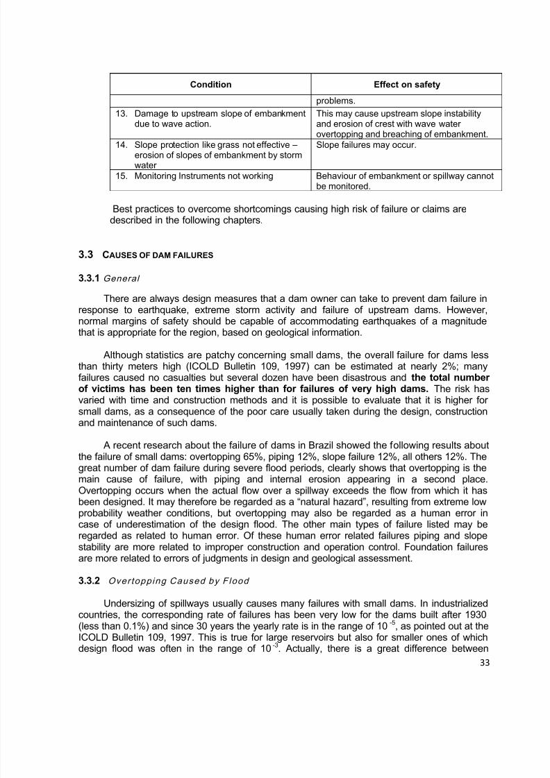
Condition Effect on safety
problems.
13. Damage to upstream slope of embankmentdue to wave action.
This may cause upstream slope instabilityand erosion of crest with wave water
overtopping and breaching of embankment.14. Slope protection like grass not effective – erosion of slopes of embankment by stormwater
Slope failures may occur.
15. Monitoring Instruments not working Behaviour of embankment or spillway cannotbe monitored.
Best practices to overcome shortcomings causing high risk of failure or claims aredescribed in the following chapters.
3.3 CAUSES OF DAM FAILURES
3.3.1 General
There are always design measures that a dam owner can take to prevent dam failure inresponse to earthquake, extreme storm activity and failure of upstream dams. However,normal margins of safety should be capable of accommodating earthquakes of a magnitudethat is appropriate for the region, based on geological information.
Although statistics are patchy concerning small dams, the overall failure for dams lessthan thirty meters high (ICOLD Bulletin 109, 1997) can be estimated at nearly 2%; manyfailures caused no casualties but several dozen have been disastrous and the total numberof victims has been ten times higher than for failures of very high dams. The risk hasvaried with time and construction methods and it is possible to evaluate that it is higher for
small dams, as a consequence of the poor care usually taken during the design, constructionand maintenance of such dams.
A recent research about the failure of dams in Brazil showed the following results aboutthe failure of small dams: overtopping 65%, piping 12%, slope failure 12%, all others 12%. Thegreat number of dam failure during severe flood periods, clearly shows that overtopping is themain cause of failure, with piping and internal erosion appearing in a second place.Overtopping occurs when the actual flow over a spillway exceeds the flow from which it hasbeen designed. It may therefore be regarded as a “natural hazard”, resulting from extreme low probability weather conditions, but overtopping may also be regarded as a human error incase of underestimation of the design flood. The other main types of failure listed may beregarded as related to human error. Of these human error related failures piping and slope
stability are more related to improper construction and operation control. Foundation failuresare more related to errors of judgments in design and geological assessment.
3.3.2 Overtopping Caused by Flood
Undersizing of spillways usually causes many failures with small dams. In industrializedcountries, the corresponding rate of failures has been very low for the dams built after 1930(less than 0.1%) and since 30 years the yearly rate is in the range of 10 -5, as pointed out at theICOLD Bulletin 109, 1997. This is true for large reservoirs but also for smaller ones of whichdesign flood was often in the range of 10-3. Actually, there is a great difference between

8/12/2019 ICOLD Small Dams Sept 2011
http://slidepdf.com/reader/full/icold-small-dams-sept-2011 34/149
34
specific exceptional flood around the world and the following table lists order of magnitude (butnot maximum) 10 000 year flood flows for different climates and catchment area.
Table 3.2 – Order-of-magnitude ten thousand year flood discharge in m3/s (Bulletin 109, 1997)
Catchment Area (km2) 2 km2 10 km2 50 km2
Climates with moderate rainfall (Northern Europe,Russia, Canada, North-West USA)
10 30 100
Intermediate climates (Mediterranean, Central America, South America)
30 100 300
Climates with extreme rainfall (South and East Asia) 100 300 1000
Worldwide Maximum of registered values 200 700 2000
In some cases, the overtopping causes a general sliding of the downstream part of the
dam embankment then a rather large initial breach. But in most cases, the initial breachresulting from the toe erosion is relatively narrow, as in case of piping, and may or not widenaccording to cross section and materials characteristics. For a same dam and same initial planof breach, breach flow is higher for overtopping than for piping, due to higher water level andarriving flow.
Over 3% of dam failures occurred due to the failure of a dam further upstream. This riskshould not be overlooked in the coming years for both existing and new dams. Nor shouldpartial obstruction of the spillways by vegetation or floating debris be forgotten.
During extreme flood occurred in Czech Republic in 2002, there were 23 small damsfailed after dam overtopping. About 50 others small dams had been strongly damaged at this
time. At Figures 3.1 (A) and (B) are presented some photos of small dams breached byovertopping during this time at the Czech Republic.
(A) (B)Fig. 3.1 – A small dam during the overtopping (A) and after the failure(B). (Czech Republic).

8/12/2019 ICOLD Small Dams Sept 2011
http://slidepdf.com/reader/full/icold-small-dams-sept-2011 35/149
35
Fig. 3.2 – Massive dam break overtopping, during extremely high floods in the CzechRepublic.
(A) (B)Fig. 3.3 – (A) Paraguaçu embankment dam failure by overtopping, after severe flooding in
Brazil. (B) Downstream erosion damages at an embankment road access, in January, 2007.
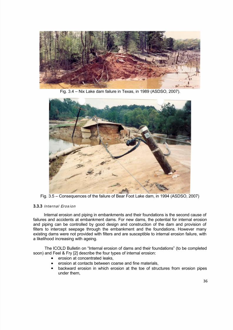
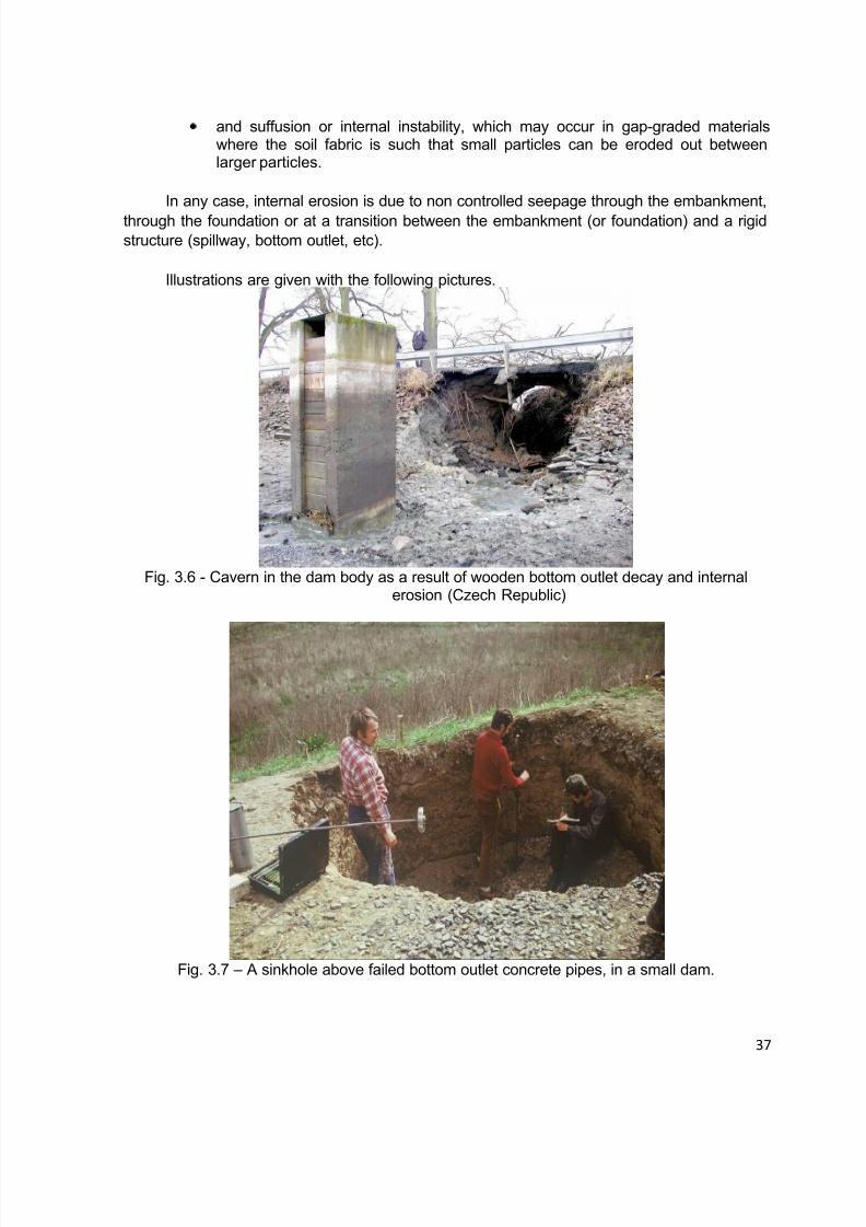
At Figures 3.4 and 3.5 are presented the failures of small dams Nix Lake and Bear Foot Lake,
in Texas, USA, by overtopping, as presented by Purkeypile and Samuelson, at the ASDSO Annual Conference, in Sept/ 2007 [1].
8/12/2019 ICOLD Small Dams Sept 2011
http://slidepdf.com/reader/full/icold-small-dams-sept-2011 36/149
36
Fig. 3.4 – Nix Lake dam failure in Texas, in 1989 (ASDSO, 2007).
Fig. 3.5 – Consequences of the failure of Bear Foot Lake dam, in 1994 (ASDSO, 2007)
3.3.3 Internal Eros ion
Internal erosion and piping in embankments and their foundations is the second cause offailures and accidents at embankment dams. For new dams, the potential for internal erosionand piping can be controlled by good design and construction of the dam and provision of
filters to intercept seepage through the embankment and the foundations. However manyexisting dams were not provided with filters and are susceptible to internal erosion failure, witha likelihood increasing with ageing.
The ICOLD Bulletin on “Internal erosion of dams and their foundations” (to be completedsoon) and Feel & Fry [2] describe the four types of internal erosion:
erosion at concentrated leaks,erosion at contacts between coarse and fine materials,backward erosion in which erosion at the toe of structures from erosion pipesunder them,
8/12/2019 ICOLD Small Dams Sept 2011
http://slidepdf.com/reader/full/icold-small-dams-sept-2011 37/149
37
and suffusion or internal instability, which may occur in gap-graded materialswhere the soil fabric is such that small particles can be eroded out betweenlarger particles.
In any case, internal erosion is due to non controlled seepage through the embankment,
through the foundation or at a transition between the embankment (or foundation) and a rigidstructure (spillway, bottom outlet, etc).
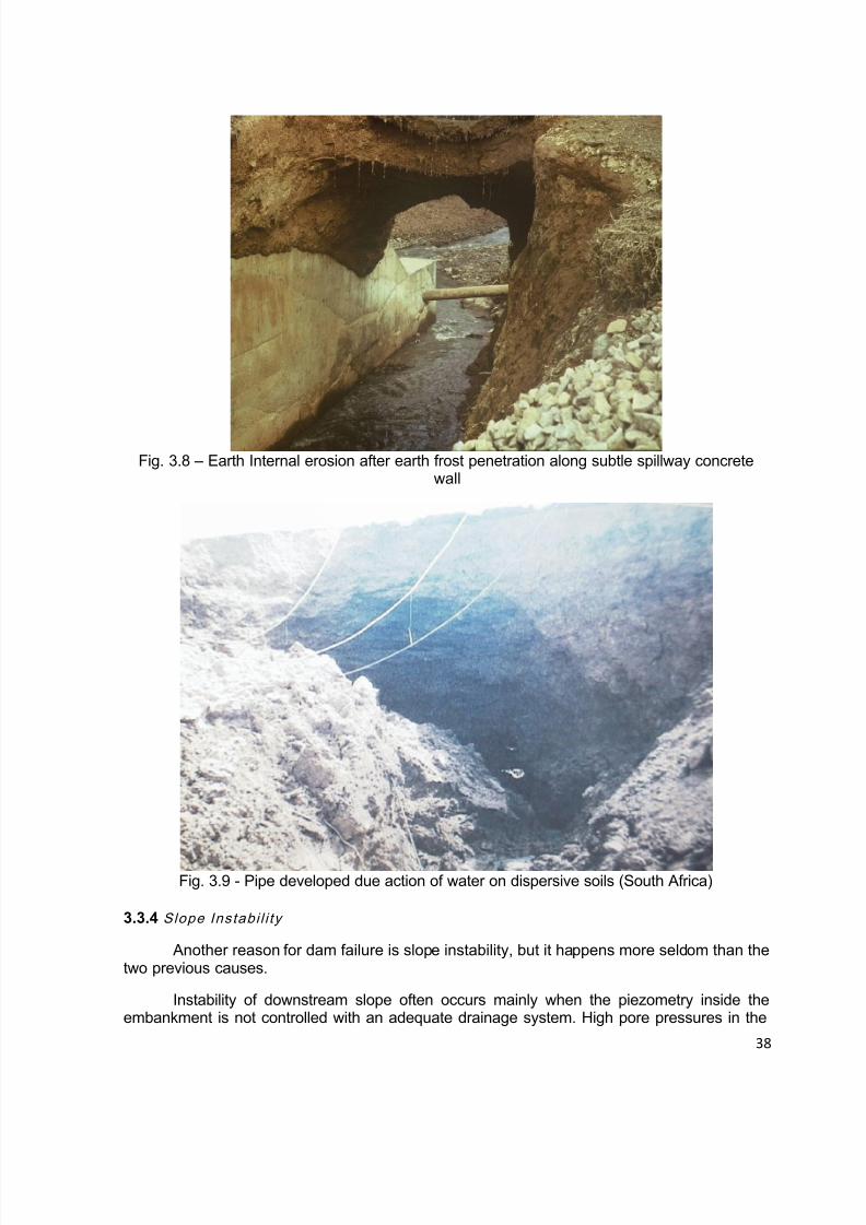
Illustrations are given with the following pictures.
Fig. 3.6 - Cavern in the dam body as a result of wooden bottom outlet decay and internalerosion (Czech Republic)
Fig. 3.7 – A sinkhole above failed bottom outlet concrete pipes, in a small dam.
8/12/2019 ICOLD Small Dams Sept 2011
http://slidepdf.com/reader/full/icold-small-dams-sept-2011 38/149
38
Fig. 3.8 – Earth Internal erosion after earth frost penetration along subtle spillway concretewall
Fig. 3.9 - Pipe developed due action of water on dispersive soils (South Africa)
3.3.4 Slope Instabi l i ty
Another reason for dam failure is slope instability, but it happens more seldom than thetwo previous causes.
Instability of downstream slope often occurs mainly when the piezometry inside theembankment is not controlled with an adequate drainage system. High pore pressures in the

8/12/2019 ICOLD Small Dams Sept 2011
http://slidepdf.com/reader/full/icold-small-dams-sept-2011 39/149
39
downstream part of the embankment may lead to circular rupture of this face, especially incase of a steep slope.
Instability of upstream slope often occurs after a rapid drawdown of the reservoir, whenpermeability of the material is too low to allow dissipation of pore pressure (Fig. 3.10).
Fig. 3.10 – Sliding of upstream slope of a homogeneous embankment dam after rapiddrawdown (France)
3.4 REFERENCES
[1] PURKEYPILE, D.; SAMUELSON, W. D. (2007) - “Historical Dam Failure in Texas”,
Annual Conference ASDSO, Austin, Texas, USA.
[2] FELL, R. and FRY, J.J. (2007). The state of the art of assessing the likelihood of internalerosion of embankment dams, water retaining structures and their foundations. InInternal Erosion of Dams and their Foundations. Editors R.Fell and J.J Fry . Taylor andFrancis, London. 1-24.

8/12/2019 ICOLD Small Dams Sept 2011
http://slidepdf.com/reader/full/icold-small-dams-sept-2011 40/149
40
4. LEGISLATION & DECOMMISSIONING
4.1 INTRODUCTION
As a general rule, protection of persons and property is a responsibility of the Government,who must legislate (create regulation) and enforce the rules through administrative bodies(agency, department, office etc) to provide for the safety and security of the people, propertyand environment. That is why dam design, construction, rehabilitation, enlargement, alteration,operation, monitoring, maintenance, repair, breach, abandonment and removal must rely on alegal frame that establishes rights, responsibilities and duties of the parties involved [1].
Failure of a dam, even a small one, can result in fatalities, loss of water supply, propertydestruction and environmental damage.
Fig. 4.1 – Busek pond in Czech Republic – dam break after overtopping in August 1991(extreme summer raining) [2].
International experience shows higher risk from small, rural dams rather than fromlarger, well-engineered dams [3]. According to the Bureau of Reclamation of the USA, 87% ofthe victims of dam disasters were related to small dam failures, between 1970 and 1997.
Therefore, it is paramount that Governments clearly define the responsibilities of theowner and establish a regulatory body with dam safety as its primary concern, completelyindependent from entities currently owning, operating or using dams.
4.2 THE REGULATION
Regulation must cover dams and levees in a coherent manner, and the basic frameworkshould be the same for all dams, regardless of whether they are for electricity production,water supply, irrigation, flood control or other purposes.
Requirements for dams should vary on the basis of dam and reservoir size. Size isbased on criteria combining dam height and reservoir capacity, being intuitively true that a

8/12/2019 ICOLD Small Dams Sept 2011
http://slidepdf.com/reader/full/icold-small-dams-sept-2011 41/149
41
small dam impounding a lot of water may be as much of a danger as a high dam impoundinglittle water.
Recent changes in French regulation changed in 2007 the dam classification system,introducing a graded system with four classes of dams [4]:
A: m20 H B: 10 < H < 20 m and 200V H 2 (V in hm3)
C: 5 < H < 10 m and 20V H 2 D: 2 < H < 5 m
The authorities may in some cases modify the classification if there are specialcircumstances.
The new French classification replaces the all-or-nothing system, whereby dams listedas a potential danger to public safety absorb massive supervision and monitoring resources,while others are frequently ignored. It must be acknowledged by Governments that even small
dams are not without risks.
According to the above referred graded system, responsibilities and requirements aredefined as it will be further explained.
The USA Model Law for State Supervision of Safety of Dams and Reservoirs adopts adifferent classification system. According to this Model Law, the Dams are defined as anyartificial barrier with ability to impound water and which is: H ≥ 7,5 m and V > 18,450 m3, or V ≥61,500 m3 and H > 2 m (please note that in the USA this type of dam regulation is a Statematter, not a Federal one, and in some States we may find different definitions according totheir own experience and needs).
The American Model establishes a Hazard Potential classification that does not reflect inany way on the current condition of the dam (safety, structural integrity etc), but in the possibleadverse consequences of the release of stored water due to failure or mis-operation of thedam [6]:
I) High Hazard Potential Dam: dam’s failure or mis-operation will probably cause lossof human life (even if it is only one person);
II) Significant Hazard Potential Dam: no probable loss of human life but can causemajor economic loss, environmental damage, disruption of lifeline facilities, or impact otherconcerns;
III) Low Hazard Potential Dam: no probable loss of human life and low economicand/or environmental losses (losses mostly limited to owner’s property).
Regardless of which classification system each country adopts, it is important that theRegulation establishes a Risk Prioritization Criteria and based on this classification, definesresponsibilities and requirements.
4.3 THE SUPERVISING AUTHORITY
A unit of the Government must be designated by law to be responsible forimplementation and administration of the Regulation. The Supervising Authority shall be

8/12/2019 ICOLD Small Dams Sept 2011
http://slidepdf.com/reader/full/icold-small-dams-sept-2011 42/149
42
administered and directed by someone clearly qualified by training and experience in the issueof dam safety.
The Supervising Authority is responsible for enforcing the Regulation and ensuring thatthe Owner complies with his responsibilities; this means that the staff in charge of the
supervision must possess sufficient skills and knowledge to be able to judge if the Owner’sefforts are commensurate to his duties.
Initially the Supervising Authority or the Owners (depending of the country regulation)should conduct an inventory of dams to determine:
a) name and address of the owner;b) the location, type, size, purpose and height of the dam;c) storage capacity;d) as accurately as may be readily obtained, the area of the drainage basin, rainfalland stream flow records, flood-flow records and estimates;e) classification of the dam according to the hazard potential risk.
Based on this inventory, the Supervising Authority shall classify the dams according totheir risk (potential and present) and identify the small dams with a high risk accordingly to theRisk Prioritization Criteria.
The total number of small dams to be submitted to surveillance by an inspector cannotbe excessive, in order that each dam shall have its safety conditions appropriately checked.
Also, it is suggested that the dam inspectors exchange their experience, periodicallyparticipating in workshops and seminars.
In France, the regional supervisors shall have the support of teams of specialists(engineers with experience in civil, geotechnical, hydraulic, hydrological and risk engineeringapplied to water-retaining works) operating nationwide[4].
Table 4.1 – Duties involved according into the French dam classesITEM A B C D
Technical and administrativeapproval
yes yes yes yes
Attendance at foundationexcavation acceptance inspection
recommended recommended possible no
Inspection of completed schemeand verification of conformity
yes yes yes no
Approval of operating surveillanceprocedures
yes yes yes no
Periodic inspection 1 year 1 to 5 years 1 to 10 years noObs. - Please see item 4.2 above for the French dam classification system.
The Supervising Authority also shall have the power to adopt rules, standards andrequirements for the design, construction, reconstruction, enlargement, alteration, operation,monitoring, maintenance, modification, repair, breach, abandonment and removal of dams andreservoirs to carry out the purpose of the Regulation.
To exemplify some of the responsibilities of this Authority in practical terms, the followingtable presents the duties of this body in France regarding their four dam classes [4]:
8/12/2019 ICOLD Small Dams Sept 2011
http://slidepdf.com/reader/full/icold-small-dams-sept-2011 43/149
43
Whenever the Supervising Authority finds that any owner or person has violated aprovision of the Regulation it may [5]:
i) issue an administrative order requiring any such person or company to comply with
his/hers/its duties;ii) bring a civil action against the violator;iii) levy a civil administrative penalty (fine);iv) petition the Attorney General (or its equivalent) to bring a criminal action.
The use or application of any of these remedies shall not preclude recourse to any of theother remedies prescribed.
4.4 THE OWNER
The responsibility for constructing, operating and maintaining a safe dam rests with the
owner. Dam owners should be aware of their legal responsibilities for the continued safeoperation of their dams and the structure's maintenance and inspection requirements.Negligence by owners in fulfilling these responsibilities can lead to the creation of extremelyhazardous conditions which may lead to a potential dam failure and thereby threatendownstream residents and properties.
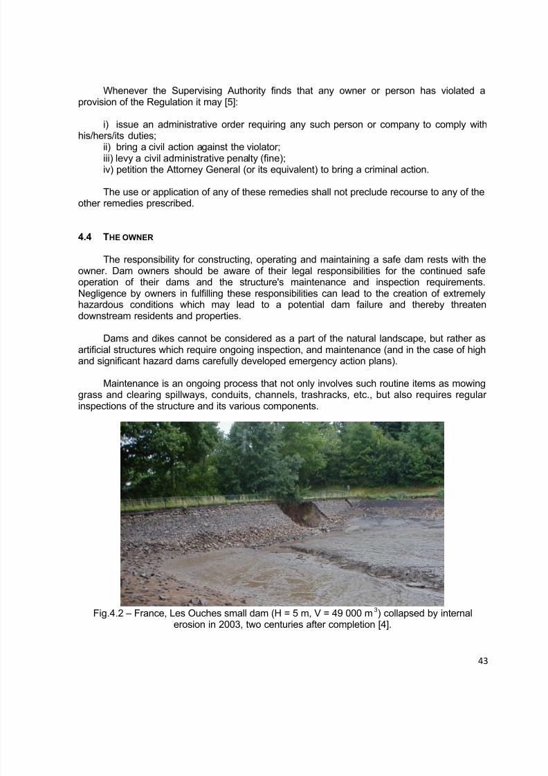
Dams and dikes cannot be considered as a part of the natural landscape, but rather asartificial structures which require ongoing inspection, and maintenance (and in the case of highand significant hazard dams carefully developed emergency action plans).
Maintenance is an ongoing process that not only involves such routine items as mowinggrass and clearing spillways, conduits, channels, trashracks, etc., but also requires regular
inspections of the structure and its various components.
Fig.4.2 – France, Les Ouches small dam (H = 5 m, V = 49 000 m3) collapsed by internalerosion in 2003, two centuries after completion [4].

8/12/2019 ICOLD Small Dams Sept 2011
http://slidepdf.com/reader/full/icold-small-dams-sept-2011 44/149

8/12/2019 ICOLD Small Dams Sept 2011
http://slidepdf.com/reader/full/icold-small-dams-sept-2011 45/149
8/12/2019 ICOLD Small Dams Sept 2011
http://slidepdf.com/reader/full/icold-small-dams-sept-2011 46/149
46
The suspended solids contained in runoff tend to settle in the quiescent reservoir waters.In industrialized areas these sediments may contain contamination such as metals, oil andgrease and many other chemicals. In rural areas these sediments may contain contaminantssuch as pesticides and herbicides from agricultural operations. The quantity and concentrationof sediments, and the rate at which they will be returned to the fluvial system are also a major
concern.
Sediment disposal is a significant issue to be resolved when considering damdecommissioning. The sediments regularly concentrated in the bottom of the reservoir couldrequire adequate treatment or removal to avoid environmental damage downstream.
Removal of the saturated sediments from the reservoir and disposing of it on land isexpensive. Therefore, allowing the sediments to be flushed downstream as a dam is removedhas been the most common practice to-date in the USA. This method has a detrimental effecton the water quality; however, the streams restore themselves after a period of time after theflushing has been allowed. This method has been used on small dams and has also beenproposed for large dam decommissioning [9].
The decommissioning can be proposed by the owner or by the regulator and should beapproved by the competent Authority responsible for dam safety. After the approval, a projectplan must be prepared in accordance to the regulation.
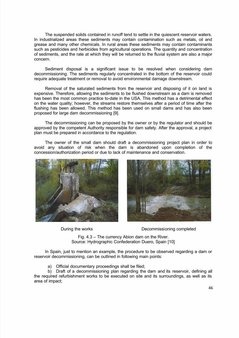
The owner of the small dam should draft a decommissioning project plan in order toavoid any situation of risk when the dam is abandoned upon completion of theconcession/authorization period or due to lack of maintenance and conservation.
During the works Decommissioning completed
Fig. 4.3 – The currency Abion dam on the River.Source: Hydrographic Confederation Duero, Spain [10]
In Spain, just to mention an example, the procedure to be observed regarding a dam orreservoir decommissioning, can be outlined in following main points:
a) Official documentary proceedings shall be filed;b) Draft of a decommissioning plan regarding the dam and its reservoir, defining all
the required refurbishment works to be executed on site and its surroundings, as well as itsarea of impact;

8/12/2019 ICOLD Small Dams Sept 2011
http://slidepdf.com/reader/full/icold-small-dams-sept-2011 47/149
47
c) The decommissioning plan should include the necessary measures to be taken toguarantee the safety of the area, especially the capacity of outflow of water as well as toguarantee the stability of permanent structures without causing any adverse impact upstreamand downstream and without affecting the fixed structures which might be in service;
d) The project shall require the processing of an Environmental Impact Evaluation
clearance which varies from case to case;e) This project should be preapproved by the competent Authority for safety of damsand reservoirs.
Once the decommissioning project is executed, the competent authority for safety ofdams and reservoirs will carry out an inspection of the site and its area of impact beforeissuing the concerned report which will be required for the final approval of thedecommissioning procedure.
In Spain, about 25 decommissioning works have been implemented up to this date. All ofthem are small dams with 1 to 8 meters of height.
In the USA over 450 dams have been decommissioned and their experience in this fieldshould be taken into account by anyone researching the topic.
Decommissioning is often not adequately considered when evaluating dam safetyupgrades, but it is a reality that engineers and dam owners will be facing more and more in thenext few decades.
There are many aspects to a dam decommissioning that must be considered by anyoneinterested on the subject, whether it is for the purpose of decommissioning an actual dam or toset a regulation regarding dam decommissioning. These aspects are thoroughly examined inthe bulletin on decommissioning guidelines, developed by the Operations, Monitoring andDecommissioning of Dams Committee, that is under publication by the ICOLD.
4.6 CONCLUSION
Formal regulation by Government play an essential role in promoting increased physicaland environmental safety, responding to a social need and requirement. The regulation shallconsider the four main phases regarding a dam: planning-approval, construction, operationand eventual closure.
Governments must focus on supervision and monitoring of dams, small and large, sincepotential losses in lives and property damage caused by flooding are increasing asdevelopment progresses bottomland alongside rivers. Considering the large number of small
dams in each country it is essential to establish a dam risk prioritization criteria, andconcentrate attention and efforts on the high hazard small dams, in a first stage.
It is paramount that the supervision and monitoring activities are conducted with thenecessary skill, according to the size and potential risk of the dam, in a context of clearassignment of roles and duties of the Owners, Concession Holders and Supervising Authority

8/12/2019 ICOLD Small Dams Sept 2011
http://slidepdf.com/reader/full/icold-small-dams-sept-2011 48/149
48
4.7 REFERENCES
[1] ABADJIEV,C.B. (2009)- “Small Dams Legislation”, Personal contribution received fromBulgaria;
[2] POLACEK, J. (2008) – Personal Contribution received from Czech Republic;
[3] WORLD BANK GOOD PRACTICES NOTES (2008) - “Safety of Small/Rural Dams andBarrier Lake Management”, July 2008
[4] CRUCHON P., DEGOUTTE G., LE DELLIOU P., MONIÉ N., ROYET P. (2009) – “Newregulations on the safety of dams and levees in France”, ICOLD-CIGB XXXII Congress,Brasilia, May 2009
[5] ASDSO – “Dam ownership – Responsibility and Liability”, Association of State DamSafety Officials, USA
[6] USCOLD (1970) – “Model Law for State Supervision of Safety of Dams and Reservoirs”,United States Committee on Large Dams, USA, 1970
[7] USSD – “Committee on Dam Decommissioning”, United States Society on Dams, USA, August 2001.
[8] OLDHAM K. (2009) – “Decommissioning Dams – Costs and Trends”, Water PowerMagazine, February 2009.
[9] DeHeer, Lee (2001) – “Bridging the Gap: Meeting the World's Water and EnvironmentalResources Challenges 2001”, American Society of Civil Engineers, USA, June 2001.
[10] Restauración de Ríos – “Guía metodológica para la elaboración de proyectos”.Ministerio de Medio Ambiente, Spain, 2007.
[11] Water Act No 254/2001 (renewed at 2010), Czech Republic, § 61 and 62 concerning ofDam Safety.
[12] Notice No 471/2001 (renewed at 2010), Czech Republic, concern to Dam Surveillanceand Supervision and Classification.

8/12/2019 ICOLD Small Dams Sept 2011
http://slidepdf.com/reader/full/icold-small-dams-sept-2011 49/149
49
5. FEATURES OF THE DESIGN OF SMALLEMBANKMENT DAMS
5.1 INTRODUCTION
As many ICOLD bulletins have been drafted for large dams, the application to smalldams is documented in this bulletin. As 85% to 95% of the small dams built in the differentcountries are earthfill dams, this item the design of earthfill and rockfill dams are presented,trying to point out the best practice to be used in the different countries. More recently, with theboom of construction of small water power stations, small dams are usually been built forpower generation.
The prime purpose of these dams is storage, mainly for irrigation or water supply. Acommon multipurpose project involving small dams combines storage, flood control and
recreational uses.
Design criteria and typical features for small dams are generally different from those ofhigh dams, because the construction methods focus upon economy. So the risks mayincrease and corresponding accidents may cause significant victims. Little attention is given todownstream hazard from floods caused by the failure of small dams; yet this is frequently themajor the case during the severe rainy season.
It is important to emphasize that for new dams, no high risk can be accepted foreconomical reasons. The knowledge is available to build safe dams.
Criteria for Design: The basic principle of design is to produce a satisfactory functional
structure at a minimum total cost. Consideration must be given to maintenance requirementsso that economies achieved in the initial cost of construction will not result in excessivemaintenance costs. For minimum cost the dam must be designed for maximum utilization ofthe most economical materials available, including materials which must be excavated for itsfoundation and for appurtenant structures.
An earthfill dam must be safe and stable during all phases of construction and operationof the reservoir. To accomplish this, the following criteria must be met:
The embankment must be safe against overtopping during occurrence of the inflowdesign flood by the provision of sufficient spillway and outlet capacity;
The slopes of the embankment must be stable during construction and all conditionsof operation, including rapid drawdown of the reservoir;
Seepage flow through the embankment foundation and abutment must be controlled,so that no internal erosion takes place and so there is no sloughing in the area where theseepage emerges. The amount of water lost through seepage must be controlled so that isdoes not interfere with planned project functions;
The embankment must be safe against overtopping by wave action;
8/12/2019 ICOLD Small Dams Sept 2011
http://slidepdf.com/reader/full/icold-small-dams-sept-2011 50/149
50
The upstream slope must be protected against erosion by wave action, and crest and thedownstream slope must be protected against erosion due to wind, rain and cattle.
Summary of Wrong Practices Followed for Small Dams
Summary of wrong practices, too often used, are summarized below:
Foundations not investigated or investigated to a limited standard; Hydrology study not done. Furthermore for smaller catchment areas less data is
available and empirical methods are usually used; Freeboard not determined; No camber provided; Soil not appropriately compacted; Seepage control not designed to standard; Wrong material sometime used (e.g. dispersive clays); Wrong equipment used during construction;
Erodible by-wash spillways, cutback erosion of spillway; No slope protection; No adequate features around outlet pipes; Part time (and not full time) construction monitoring to confirm quality; No routine inspections of the dam during its life; No monitoring instruments installed; Adoption of lower cost with higher risk.
Summary of Good Practices to be Followed for Small Dams
Summary of the best practices normally used are summarized below:
Investigation of foundations (to a minimum depth of 4-5m or the height of the dam)and excavation of the organic and others inappropriate soils at the dam foundation;
Hydrology study, using at minimum empirical methods; Choose cohesive materials for embankment, which are more stable during
overtopping; Use appropriate and durable material for slope protection; Adopt a standard design for filters and drains; Use appropriate equipment for construction (especially for compaction) and monitor
construction quality; Embed outlet pipes into concrete;
Access to outlet works necessary during floods and for maintenance; Cattle not allowed on dam slopes and abutments; Pipes are not allowed through or over embankments as they may cause piping
through removal of fines or pipe bursts. Install some monitoring instruments and perform routine inspections during dam
operation.

8/12/2019 ICOLD Small Dams Sept 2011
http://slidepdf.com/reader/full/icold-small-dams-sept-2011 51/149
51
5.2 DESIGN FLOODS
Inadequate flood handling capacity not meeting design standards is normally caused byunderestimating the design flood, not acknowledging the effect of the upstream approachchannel on the hydraulic gradient or not ensuring that the dam was constructed with its total
freeboard over the entire crest length of the dam. The hydraulic control must be correctlydefined for the design flow by determining the hydraulic flow and energy lines based on thecorrect sectional information.
In rural areas, in which usually is very seldom inhabitants downstream, it is applicable thedesign floods indicated in Table 5.1, like in South Africa.
Table 5.1 – Suggested Minimum Design FloodsPotential Hazard Classification -
PHCPHC = 1 PHC = 2
Recommended design flood 1:20 year 1:100 year
Safety evaluation check flood 1:50 year 1:200 year
The following are important regarding Table 5.1:
No overtopping to occur for this flood and freeboard remaining for protection againstwave run-upOverflowing is acceptable, but very limited in duration and depth, and risk ofcatastrophic failure must be very low.Floods to be reduced when upstream control is applicable.Flood attenuation in the reservoir above full supply level studies will determine thedischarge flood.
The owner may adopt a lower risk as indicated and in any case when the incrementalcost for upgrading to a higher standard is low.
In more populated areas and countries like France, for instance, the draft Guidelines for thedesign of dams spillways contains the following recommendations for small embankmentdams.
Table 5.2 – Suggested Minimum Design Floods in France (April, 2011)
Potential Hazard Classification –
PHCPHC = 1 PHC = 2
Recommended Design Flood 1:300 year 1:1000 year
Safety Evaluation Check Flood 1:1000 year 1:10000 year
It is possible to see that the safety considerations could differ from one country to another,depending to the attitude of the society in regards to acceptable risk and on the level ofeconomic development. But is always important to increase the requirements related to thedam safety, in order to reduce the risk and avoid any possible dam overtopping during severestorms. Most of the small dams are embankment dams, and this type of structure not acceptsovertopping without the risk of failure.

8/12/2019 ICOLD Small Dams Sept 2011
http://slidepdf.com/reader/full/icold-small-dams-sept-2011 52/149
52
During the life of the dam the potential hazard due to developments in the dam break floodingarea can change. Upgrading to a higher Potential Hazard Classification (PHC) class is thennecessary.
5.3 HOMOGENOUS AND ZONED EMBANKMENTS DESIGN
Essentially, designing an earthfill dam embankment primarily involves determining thecross section that, when constructed with the available material, will fulfill its required functionwith adequate safety at minimum cost.
Where considerations is given to the possible loss of life, to the possibility of costlyproperty damage, and to the waste of money incidental to the failure of a dam, ample
justification is provided for conservative procedures. For small dams, where the cost ofexplorations and laboratory testing of the embankment material for analytical studies togetherwith the cost of the engineering constitutes an inordinate proportion of the total cost of thestructure, the practice of designing on the basis of successful structures and past experience
becomes even more appropriate.
In China, for instance, as can be seen in publication [1], the dam slopes are to bedetermined mainly based on the nature of the foundation, the strength of soil material, the drydensity, the dam height and the downstream drainage condition. But for small dams (H<15 m)stability analyses are not required, and reference may then be made to the available data fromexisting dams, as can be seen in Appendix I.
Considerable progress has been made in investigations and studies directed toward thedevelopment of methods that will offer a comprehensive analysis of embankment stability.Present practice in determining the required cross section of an earth dam consists largely ofdesigning to the slopes and characteristics of existing successful dams, making analytical and
experimental studies for unusual conditions, and controlling closely the selection andplacement of embankment materials.
Although the above practice may be criticized as being overly cautious and extravagant,no better method has been conclusively demonstrated. Where considerations is given to thepossible loss of life, to the possibility of costly properly damage, and to the waste of moneyincidental to the failure of a constructed dam, ample justification is provided for conservativeprocedures, as pointed out by the Bureau of Reclamation, 1987(3rd Edition).
Most small dams (85% to 95%) involves the construction of embankment dams as aconsequence of a method that is simple, straightforward and suitable for those sites wherethere is sufficient and properly material. Protection from seepage and slipping is provided by
flattening the slopes, that is from a 2:1 to 3:1 gradient (H:V), and providing a thick covering oftopsoil to carry any seepage to the toe of the dam.
5.3.1 Homo geneou s Type
Embankment materials vary widely from place to place, particularly in respect togradation and permeability. If the difference in permeability between the impervious core andthe downstream batter is great, no internal drainage is required. If the variation of thepermeability between the inner core and the outer zones is not sufficient, then theembankment will become saturated after prolonged storage at full supply. Consequently, the
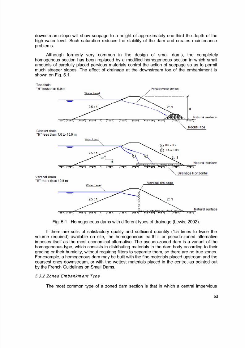
8/12/2019 ICOLD Small Dams Sept 2011
http://slidepdf.com/reader/full/icold-small-dams-sept-2011 53/149
53
downstream slope will show seepage to a height of approximately one-third the depth of thehigh water level. Such saturation reduces the stability of the dam and creates maintenanceproblems.
Although formerly very common in the design of small dams, the completely
homogenous section has been replaced by a modified homogeneous section in which smallamounts of carefully placed pervious materials control the action of seepage so as to permitmuch steeper slopes. The effect of drainage at the downstream toe of the embankment isshown on Fig. 5.1.
Fig. 5.1 – Homogeneous dams with different types of drainage (Lewis, 2002).
If there are soils of satisfactory quality and sufficient quantity (1.5 times to twice thevolume required) available on site, the homogeneous earthfill or pseudo-zoned alternative
imposes itself as the most economical alternative. The pseudo-zoned dam is a variant of thehomogeneous type, which consists in distributing materials in the dam body according to theirgrading or their humidity, without requiring filters to separate them, so there are no true zones.For example, a homogenous dam may be built with the fine materials placed upstream and thecoarsest ones downstream, or with the wettest materials placed in the centre, as pointed outby the French Guidelines on Small Dams.
5.3.2 Zoned Embankm ent Type
The most common type of a zoned dam section is that in which a central impervious

8/12/2019 ICOLD Small Dams Sept 2011
http://slidepdf.com/reader/full/icold-small-dams-sept-2011 54/149
54
core is flanked by zones of materials considered more pervious, called shells. These perviouszones or shells enclose, support and protect the impervious core, the upstream pervious zoneaffords stability against rapid drawdown; and the downstream pervious zone acts as a drain tocontrol seepage and lower the phreatic surface. In many cases, a filter between theimpervious zone and downstream shell and a drainage layer beneath the downstream are
necessary. In Table 5.4 are presented some examples of zoned and homogeneous smalldams in Japan, illustrating their typical sections and also some rehabilitation measures underway in order to improve their safety conditions.
5.4 FREEBOARD
5.4.1 Defini t ion s of Freeboard
Freeboard is the vertical distance between the crest of the dam and a specified still-water reservoir water surface elevation. Common definitions of freeboard are as follows:
Normal freeboard – vertical distance from dam crest elevation to normal operatingreservoir still-water surface elevation.
Minimum freeboard – vertical distance from dam crest elevation to maximum reservoirstill-water surface elevation during inflow design flood with spillway operating
5.4.2 Freeboard Design Con siderat ion s
Freeboard must be sufficient to prevent overtopping of the dam that could result fromreasonable combinations of a number of factors, as illustrated on Figure 5.2:
Wind-generated wave action, wind setup, and wave runup;
Earthquake and/or landslide-generated waves and runup; Post-construction settlement of embankment dams and foundations; Provision for malfunction of spillways (especially gated structures) and outlet works,
and Site-specific uncertainties including flood hydrology.
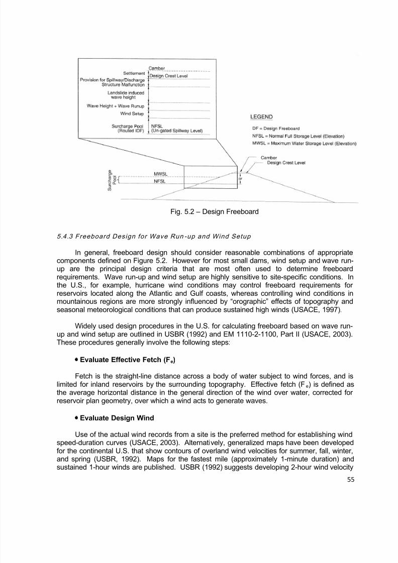
8/12/2019 ICOLD Small Dams Sept 2011
http://slidepdf.com/reader/full/icold-small-dams-sept-2011 55/149
55
Fig. 5.2 – Design Freeboard
5.4.3 Freeboard Design for Wave Run -up and Wind Setup
In general, freeboard design should consider reasonable combinations of appropriatecomponents defined on Figure 5.2. However for most small dams, wind setup and wave run-up are the principal design criteria that are most often used to determine freeboardrequirements. Wave run-up and wind setup are highly sensitive to site-specific conditions. Inthe U.S., for example, hurricane wind conditions may control freeboard requirements for
reservoirs located along the Atlantic and Gulf coasts, whereas controlling wind conditions inmountainous regions are more strongly influenced by “orographic” effects of topography andseasonal meteorological conditions that can produce sustained high winds (USACE, 1997).
Widely used design procedures in the U.S. for calculating freeboard based on wave run-up and wind setup are outlined in USBR (1992) and EM 1110-2-1100, Part II (USACE, 2003).These procedures generally involve the following steps:
Evaluate Effective Fetch (Fe)
Fetch is the straight-line distance across a body of water subject to wind forces, and islimited for inland reservoirs by the surrounding topography. Effective fetch (Fe) is defined as
the average horizontal distance in the general direction of the wind over water, corrected forreservoir plan geometry, over which a wind acts to generate waves.
Evaluate Design Wind
Use of the actual wind records from a site is the preferred method for establishing windspeed-duration curves (USACE, 2003). Alternatively, generalized maps have been developedfor the continental U.S. that show contours of overland wind velocities for summer, fall, winter,and spring (USBR, 1992). Maps for the fastest mile (approximately 1-minute duration) andsustained 1-hour winds are published. USBR (1992) suggests developing 2-hour wind velocity
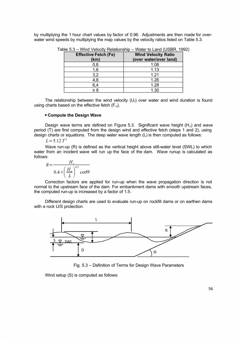
8/12/2019 ICOLD Small Dams Sept 2011
http://slidepdf.com/reader/full/icold-small-dams-sept-2011 56/149
56
by multiplying the 1 hour chart values by factor of 0.96. Adjustments are then made for over-water wind speeds by multiplying the map values by the velocity ratios listed on Table 5.3.
Table 5.3 – Wind Velocity Relationship – Water to Land (USBR, 1992)Effective Fetch (Fe)
(km)
Wind Velocity Ratio
(over water/over land)0,8 1.081,6 1.133,2 1.214,8 1.266,4 1.28≥ 8 1.30
The relationship between the wind velocity (Uf ) over water and wind duration is foundusing charts based on the effective fetch (Fe).
Compute the Design Wave
Design wave terms are defined on Figure 5.3. Significant wave height (Hs) and waveperiod (T) are first computed from the design wind and effective fetch (steps 1 and 2), usingdesign charts or equations. The deep water wave length (L) is then computed as follows:
212.5 T L
Wave run-up (R) is defined as the vertical height above still-water level (SWL) to whichwater from an incident wave will run up the face of the dam. Wave runup is calculated asfollows:
cot4.0
5.0
L
H
H R
s
s
Correction factors are applied for run-up when the wave propagation direction is notnormal to the upstream face of the dam. For embankment dams with smooth upstream faces,the computed run-up is increased by a factor of 1.5.
Different design charts are used to evaluate run-up on rockfill dams or on earthen damswith a rock U/S protection.
Fig. 5.3 – Definition of Terms for Design Wave Parameters
Wind setup (S) is computed as follows:
R
L
SWLS
DѲ
8/12/2019 ICOLD Small Dams Sept 2011
http://slidepdf.com/reader/full/icold-small-dams-sept-2011 57/149
57
D
F U S
e f
1400
2
Where Uf is the design wind velocity over water, and D = average water depth along thefetch.
The freeboard requirement for wind-generated waves is the sum of the wave run-up (R)and wind setup (S). Freeboard is generally based on maximum probable wind conditionswhen the reference elevation is the normal operating level. When estimating the freeboard tobe used with the probable maximum reservoir level, a lesser wind condition is used because itis improbable that maximum wind conditions will occur simultaneously with the maximum floodlevel (USACE, 1997).
5.4.4 First Appro ximatio ns for Freeboard Requirements
As a first estimate, the U.S. Bureau of Reclamation (USBR, 1992) uses the empiricalguidelines summarized on Table 5.3 for preliminary studies of small dams. The values shown
on Table 5.3 were based on wind velocities of 160 km/hour (100 miles/hour) for estimatingnormal freeboard and 80 km/hour (50 miles/hour) for minimum freeboard.
Table 5.4 – Freeboard Requirements for Preliminary Studies of Small Dams for rock facedslope (USBR, 1987, 1992)
Longest fetch(km)
Normal Freeboard(m)
Freeboard – MFL(*)(m)
< 1.6 1.2 0.91.6 1.5 1.24.0 1.8 1.58.0 2.4 1.816.0 3.0 2.1
(*) MFL = Maximum flood level.
A large number of dams have failed due to overtopping and consequently greaterattention must be paid to this feature. Freeboard should not be less than 1,0 m, even for smalldams, as pointed out by Lewis (2002).[4]
In the French Guidelines for Small Dams, 2006, it is recommended that the minimumfreeboard for fill (providing a safety margin from maximum water level, settlement andupstream cracking of the crest) depending on the parameter V H
2 , in which the minimumvalues are presented in Table 5.5. Of course, if calculations using more detailed formula give ahigher value for freeboard, that higher value should be used. In such a case a less rigid wavewall (e.g. gabions) can provide protection between minimum freeboard (Table 4) andcalculated freeboard.
Table 5.5 – Minimum freeboard for fill dams according to parameter V H 2
V H 2 5 30 100 200
Rmin (m) 0,40 0,60 0,80 0,70
According to practice in Czech Republic, and considering that the breakwater at some smalldams with large reservoir and long run-up of water waves can be considered.
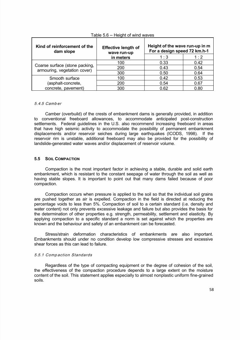
8/12/2019 ICOLD Small Dams Sept 2011
http://slidepdf.com/reader/full/icold-small-dams-sept-2011 58/149
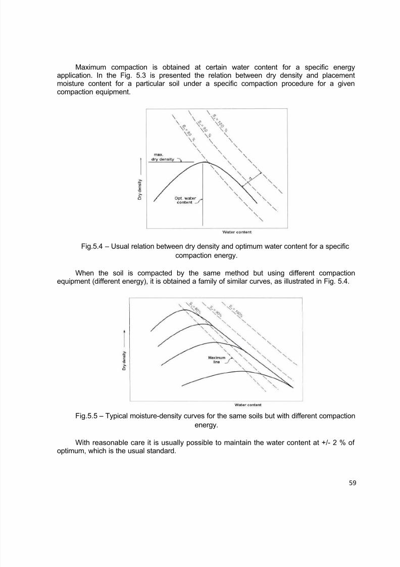
8/12/2019 ICOLD Small Dams Sept 2011
http://slidepdf.com/reader/full/icold-small-dams-sept-2011 59/149
59
Maximum compaction is obtained at certain water content for a specific energyapplication. In the Fig. 5.3 is presented the relation between dry density and placementmoisture content for a particular soil under a specific compaction procedure for a givencompaction equipment.
Fig.5.4 – Usual relation between dry density and optimum water content for a specificcompaction energy.
When the soil is compacted by the same method but using different compactionequipment (different energy), it is obtained a family of similar curves, as illustrated in Fig. 5.4.
Fig.5.5 – Typical moisture-density curves for the same soils but with different compactionenergy.
With reasonable care it is usually possible to maintain the water content at +/- 2 % ofoptimum, which is the usual standard.

8/12/2019 ICOLD Small Dams Sept 2011
http://slidepdf.com/reader/full/icold-small-dams-sept-2011 60/149
60
If the moisture content of the soil in the field is greater than the optimum, the soil shouldbe given an opportunity to dry out in storage after spreading.
If it is less, water should be added in the borrow pit or by sprinkling before compaction.The addition of water can be undertaken by:
Mixing water into the soil by cultivation with a disc plough or rotary hoe; Irrigating as the soil is spread out on the embankment; Deep ripping and irrigating the soil before excavation, also known as “borrow pit
irrigation”.
Borrow pit irrigation is usually more economical than adding water directly to theconstruction surface. It results in more even distribution of water, and saves time by avoidingthe necessity to water the construction surface between each layer.
The water content at which a soil is compacted has an effect on all the physicalproperties of the compacted soil, including the permeability. Experience indicates that an
increase in initial water content from a value somewhat below the optimum to a valuesomewhat above is likely to cause a large decrease in the coefficient of permeability.
5.5.2 Water Content Variat ion and Effect on Geomech anical Propert ies
For the core of an embankment, sealing and therefore elasticity and cohesion aredominant and strength is second in line. For the outer zones of an embankment, stability andtherefore strength is most important and elasticity not a priority.
The above provides the motivation for specification of water variation 0% to 2% ofoptimum for core impervious materials and –1% to +2% or +3% for semi-pervious materials.
The strength and elasticity values obtained in the laboratory at the specified density andoptimum moisture content of a material can be taken as design parameters if water contentand density control were done during construction in accordance with the mentioned criteria.
5.5.3 Layer Thic kness es
Layer thicknesses are to be tested with the placement and construction machines to beused during construction. Special care for proper mixing with water and effective compactionthrough the complete layer must be investigated. Test sections must also be constructed,opened and checked visually.
If layer thickness cannot be determined experimentally then layer thicknesses must be
limited to 20 cm after compaction, depending on the material. Maximum thickness aftercompaction must always be limited to 30 cm.
5.5.4 Qual i ty Control During Com pactio n
This is very important. The frequency of testing per layer and per volume placed must bespecified. A test section is normally specified with more frequent testing by Troxler and sandreplacement methods. Troxler machines must be calibrated. When soil materials in borrowareas change a new Standard Proctor maximum dry density and optimum water content

8/12/2019 ICOLD Small Dams Sept 2011
http://slidepdf.com/reader/full/icold-small-dams-sept-2011 61/149
61
characteristic must be determined. This must be used as standard to compare thecharacteristics of the placed and compacted materials.
When during compaction a layer dries out before the next layer is placed the layer mustbe reworked and recompacted at the correct water content after watering and mixing. Badly
compacted layers can cause high seepage rates and possible piping failures.
5.5.5 Compaction in Con fined Areas
In areas inaccessible to large compaction machines compaction by smaller machines inthinner layers have to be performed. If necessary compaction by hand can be used but then at2% of optimum water content to ensure proper wetting of all soil particles. Quality assurancehere is of most importance as many failures of earthfill dams occurred due to piping along saythe bottom outlet pipe caused by below standard compaction (Oosthuizen 1985).
Figure 5.6 shows a pipe with intact seepage collars, with the photograph taken after aninternal erosion failure of a small dam. The fact that anti-seep collars have not prevented many
failures implies that most of the crack features causing the failure occurred in the earthfilloutside the collars, probably as a consequence of the poor compaction of the soil between thecollars.
In some cases internal erosion occurred through hydraulic fractures in surroundingembankment soils that were dispersive clays, but not along the conduit as is often presumed.
Fig. 5.6 – Pipe with intact anti-seepage collars shortly after failure of a small dam(McCook/2004).
Seepage and piping along outlet pipes are a major cause of failure of small dams. Aspipes become larger in diameter it becomes more difficult to compact the soil properly, downthe sides of the pipe. A good precaution consists in placing draining or filtering granularmaterial on either side of the pipe over its downstream third, in order to block or drainagestrips in the fill.
5.5.6 Testin g of The Pipe

8/12/2019 ICOLD Small Dams Sept 2011
http://slidepdf.com/reader/full/icold-small-dams-sept-2011 62/149
8/12/2019 ICOLD Small Dams Sept 2011
http://slidepdf.com/reader/full/icold-small-dams-sept-2011 63/149
63
5.6.1 Found ation Watert ightness
The three following cases can be considered for homogeneous and zoned dams, aspointed out by the French Guidelines on Small Dams.
● Foundation consisting of relatively impermeable materials
It is recommended that a cut-off trench be built of compacted clay materials in order todeal with any surface cracking or heterogeneous zones. The dimensions of such a trenchshould be:
Minimum width at the base: 3 meters; Side slopes of the order of 1/1; Some meters depth with a minimum of 2 meters below natural ground level.
● Foundation with permeable layers to a depth of a few meters
The trench must cut through those layers and be anchored in a watertight layer. If thelatter is unaltered rock, after it has been cleaned and possibly its surface has been smoothed,sweeping or washing of the surface and infilling the opening joints with cement mortar, andplacing a first layer of wet (optimum moisture content (+ 2 or 3%) clay a few decimeters thick,is placed to guarantee good contact, it may be necessary to set a filter between thedownstream face of the trench and the permeable foundation materials.
● Permeable foundation to a significant depth
Grouting can be used both for a loose foundation and for a more or less cracked rockmass, with the grout adapted to the material being treated (bentonite-cement grout, speciallydesigned grouts); the cut-off will usually involve three lines of staggered drill holes; as grouting
cannot be effective at the surface, either the first few meters of grouting are relayed by the cut-off trench, or treatment is started at a certain height in the fill.
As concerning dams with an artificial water tightening element, the connection betweenthis structure in the fill and the water tightening in the foundation is a difficult point.
When the reservoir cannot be water tightened by a cut-off at the dam, the solutionconsists in sealing the reservoir basin totally or partially with a geomembrane or with a blanketof compacted clay materials (at least two layers about 0.20 meters thick each), with the latterprotected from any risk of drying out. Such techniques always result in a high price per cubicmeter of water stored, and it is always very hard to avoid any superficial cracks along theimpervious layer.
As concerns the support for these systems, it is necessary to:
Meet filter conditions for an upstream blanket; Eliminate any rough areas that might puncture the geomembrane; Avoid any risk of uplift, in particular due to gases under the geomembrane.
Flattening of steep slopes especially at the river banks to slopes meeting differentialsettlement criteria of above soils. Maximum slopes of 1V:1H is recommended where
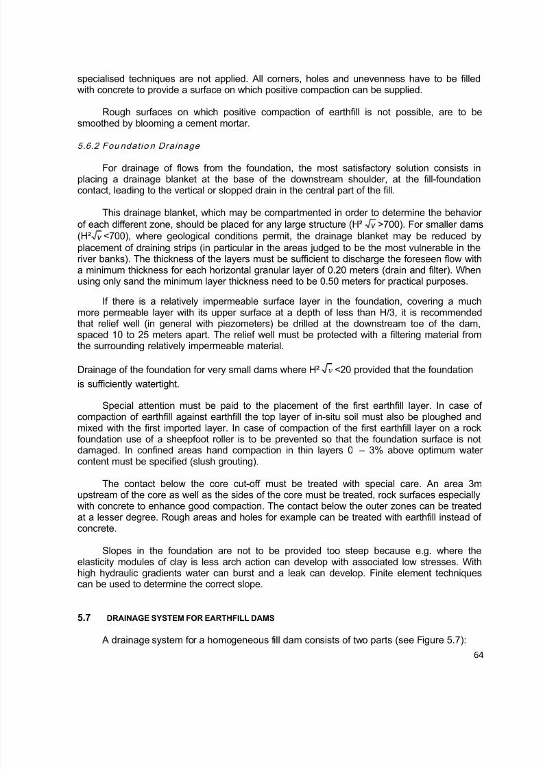
8/12/2019 ICOLD Small Dams Sept 2011
http://slidepdf.com/reader/full/icold-small-dams-sept-2011 64/149
64
specialised techniques are not applied. All corners, holes and unevenness have to be filledwith concrete to provide a surface on which positive compaction can be supplied.
Rough surfaces on which positive compaction of earthfill is not possible, are to besmoothed by blooming a cement mortar.
5.6.2 Fou ndatio n Drainage
For drainage of flows from the foundation, the most satisfactory solution consists inplacing a drainage blanket at the base of the downstream shoulder, at the fill-foundationcontact, leading to the vertical or slopped drain in the central part of the fill.
This drainage blanket, which may be compartmented in order to determine the behaviorof each different zone, should be placed for any large structure (H² v >700). For smaller dams(H² v <700), where geological conditions permit, the drainage blanket may be reduced byplacement of draining strips (in particular in the areas judged to be the most vulnerable in theriver banks). The thickness of the layers must be sufficient to discharge the foreseen flow with
a minimum thickness for each horizontal granular layer of 0.20 meters (drain and filter). Whenusing only sand the minimum layer thickness need to be 0.50 meters for practical purposes.
If there is a relatively impermeable surface layer in the foundation, covering a muchmore permeable layer with its upper surface at a depth of less than H/3, it is recommendedthat relief well (in general with piezometers) be drilled at the downstream toe of the dam,spaced 10 to 25 meters apart. The relief well must be protected with a filtering material fromthe surrounding relatively impermeable material.
Drainage of the foundation for very small dams where H² v <20 provided that the foundation
is sufficiently watertight.
Special attention must be paid to the placement of the first earthfill layer. In case ofcompaction of earthfill against earthfill the top layer of in-situ soil must also be ploughed andmixed with the first imported layer. In case of compaction of the first earthfill layer on a rockfoundation use of a sheepfoot roller is to be prevented so that the foundation surface is notdamaged. In confined areas hand compaction in thin layers 0 – 3% above optimum watercontent must be specified (slush grouting).
The contact below the core cut-off must be treated with special care. An area 3mupstream of the core as well as the sides of the core must be treated, rock surfaces especiallywith concrete to enhance good compaction. The contact below the outer zones can be treatedat a lesser degree. Rough areas and holes for example can be treated with earthfill instead ofconcrete.
Slopes in the foundation are not to be provided too steep because e.g. where theelasticity modules of clay is less arch action can develop with associated low stresses. Withhigh hydraulic gradients water can burst and a leak can develop. Finite element techniquescan be used to determine the correct slope.
5.7 DRAINAGE SYSTEM FOR EARTHFILL DAMS
A drainage system for a homogeneous fill dam consists of two parts (see Figure 5.7):
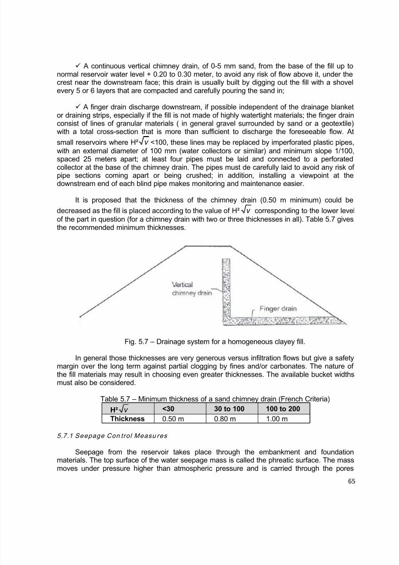
8/12/2019 ICOLD Small Dams Sept 2011
http://slidepdf.com/reader/full/icold-small-dams-sept-2011 65/149

8/12/2019 ICOLD Small Dams Sept 2011
http://slidepdf.com/reader/full/icold-small-dams-sept-2011 66/149
66
around soil particles, through fractured zones or cracks etc. Hydraulic gradient refers to non-dimensional unit change in hydraulic potential between two points in the flow medium (water).
The basic practice in seepage control design is to provide a number of seepage controlmeasures to ensure maximum water storage capability of a dam. Defensive design is
necessary to accommodate a series of unknown factors which can be as follows:
Unknown characteristics of geological and foundation materials due to limitedavailable data.
Degradation or ageing of seepage control measures or materials.
Change in the operations method of a dam.
Non conforming quality control during construction e.g. below standard compaction.
Dispersive clay materials susceptible to piping can be used in the central part of the
embankment as core to provide an impervious medium and be protected with semi-perviousmaterials not susceptible to piping in the shells.
5.7.1.1 Measures for Pervious Ground
In a case where it is impossible for engineering reasons or uneconomical to insert animpervious zone to seepage resistant ground, the quantity of seepage must be maintained inthe allowed range and seepage water must be safely discharged outside the dam withreference to Table 5.8 considering on-site conditions.
The blanket method is an example of this Seepage Control Measures.
Table 5.8 – Treatment of Pervious Ground (Japanese Criteria)Thickness of
pervious layerDesign
methodSketch Applications
ThinImpervious
zone
Provides completeimpervious effects. But it isused when the perviouslayer thickness is within 1/3of the present dam heightabove the ground.
Medium Sheet pile
Provides incompleteimpervious effects. It is not
suitable for a layercontaining pebbles. It iseffective in fine sand andsilt layers.
Impervious zone
Impervious zone
Pervious layer
Sheet pile
Sheet pilePervious layer
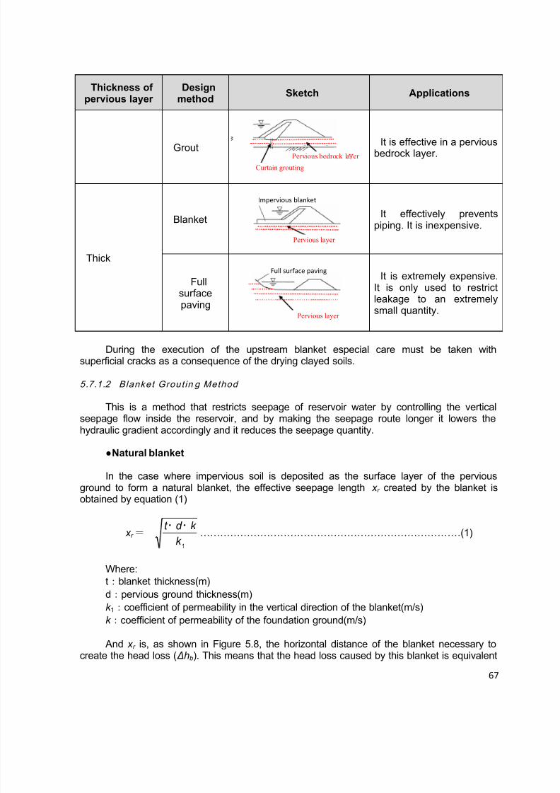
8/12/2019 ICOLD Small Dams Sept 2011
http://slidepdf.com/reader/full/icold-small-dams-sept-2011 67/149
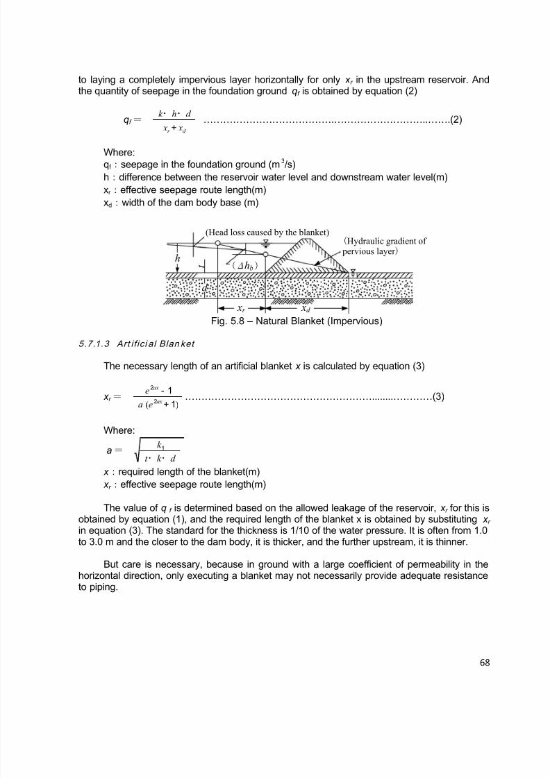
8/12/2019 ICOLD Small Dams Sept 2011
http://slidepdf.com/reader/full/icold-small-dams-sept-2011 68/149
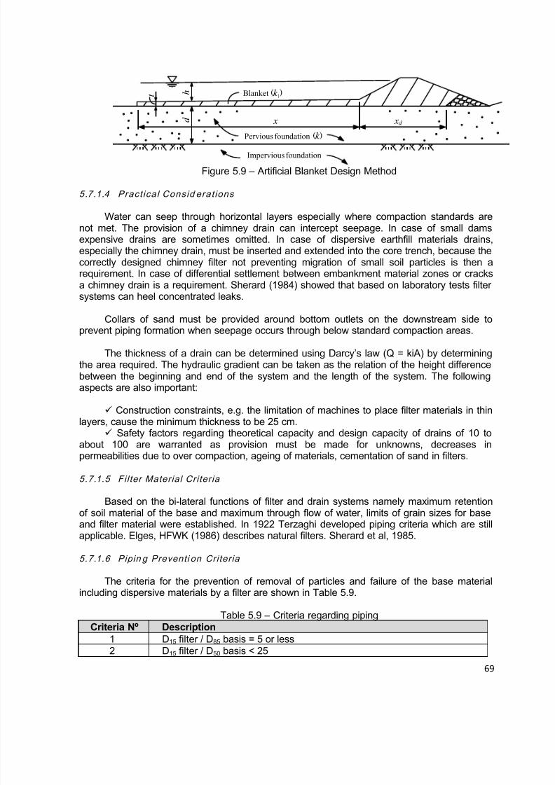
8/12/2019 ICOLD Small Dams Sept 2011
http://slidepdf.com/reader/full/icold-small-dams-sept-2011 69/149
69
Blanket (k 1)
Pervious foundation (k )
Impervious foundation
x xd d
t h
Figure 5.9 – Artificial Blanket Design Method
5.7.1.4 Pract ical Consid erat ions
Water can seep through horizontal layers especially where compaction standards arenot met. The provision of a chimney drain can intercept seepage. In case of small damsexpensive drains are sometimes omitted. In case of dispersive earthfill materials drains,especially the chimney drain, must be inserted and extended into the core trench, because thecorrectly designed chimney filter not preventing migration of small soil particles is then a
requirement. In case of differential settlement between embankment material zones or cracksa chimney drain is a requirement. Sherard (1984) showed that based on laboratory tests filtersystems can heel concentrated leaks.
Collars of sand must be provided around bottom outlets on the downstream side toprevent piping formation when seepage occurs through below standard compaction areas.
The thickness of a drain can be determined using Darcy’s law (Q = kiA) by determiningthe area required. The hydraulic gradient can be taken as the relation of the height differencebetween the beginning and end of the system and the length of the system. The followingaspects are also important:
Construction constraints, e.g. the limitation of machines to place filter materials in thinlayers, cause the minimum thickness to be 25 cm.
Safety factors regarding theoretical capacity and design capacity of drains of 10 toabout 100 are warranted as provision must be made for unknowns, decreases inpermeabilities due to over compaction, ageing of materials, cementation of sand in filters.
5.7.1.5 Filter Material Criteria
Based on the bi-lateral functions of filter and drain systems namely maximum retentionof soil material of the base and maximum through flow of water, limits of grain sizes for baseand filter material were established. In 1922 Terzaghi developed piping criteria which are stillapplicable. Elges, HFWK (1986) describes natural filters. Sherard et al, 1985.
5.7.1.6 Pipin g Preventi on Criteria
The criteria for the prevention of removal of particles and failure of the base materialincluding dispersive materials by a filter are shown in Table 5.9.
Table 5.9 – Criteria regarding pipingCriteria Nº Description
1 D15 filter / D85 basis = 5 or less2 D15 filter / D50 basis < 25

8/12/2019 ICOLD Small Dams Sept 2011
http://slidepdf.com/reader/full/icold-small-dams-sept-2011 70/149
70
3 D15 / D85 < 5 for sandy silt and clay (D85 of 0,1 to 0,5)4 D15<0,5 for fine clay (D85 from 0,3 to 0,1)5 D15<0,3 for fine silts with low cohesion and plasticity (LL<30 (D85 from 0,3
to 0,1)6 D15 < 0,2 for fine soil (D85 of 0,02)
5.7.1.7 Criteria Regard ing Permeab il ity
Criteria ensuring sufficient flow in the filter/drain are shown in Table 5.10.
Table 5.10 – Criteria for drainsCriteria number Details
1 5 < D15 filter / D15 base < 40
2The grain size associated with the 0,075 sieve size based on the
washed grading of sand must be less than 5%
Note: Laboratory studies showed that the permeability of filter sand significantly (in
portions of 100) decreases with the fines more than 5% through the 0,075 sieve size. Thewashed grading test must be used to remove the fine fraction (Cedergren, 1977).
5.7.1.8 Unifo rm Criteria
Depending on the uniform characteristics of the materials the limits for criteria number 1in Table 5.8 must be used as those shown in Table 5.11.
Table 5.11 – Filter uniformity criteriaCharacteristic Lower limit Higher limit
Uniform: D60/D10 = 3 to 4 5 40Non-uniform: rounded grains 12 40Non-uniform: sharp edge grains 6 18
5.7.1.9 Criteria for the Inh erent Stabil ity of a Filter
The Stability Relation defined as D15 (coarse) / D85 (fine) applied to 5% intervals on theparticle grain size distribution must always be smaller than 5. Sherard showed in 1984 that thecoefficient of uniformity Cu = D60 / D10 should satisfy the following conditions:
Table 5.12 – Criteria for inherent stability of a filter layerCu-value Guidelines
10 Inherent instability possible
10 < Cu < 20Inherent stability only possible in soils with grading curves with
sharp changes in bends
20 < Cu < 75The soil will be stable when the grading curve is smooth without
sharp changes in directions or significant flat zones.
5.7.1.10 Cohesio n Clay Crit eria
8/12/2019 ICOLD Small Dams Sept 2011
http://slidepdf.com/reader/full/icold-small-dams-sept-2011 71/149

8/12/2019 ICOLD Small Dams Sept 2011
http://slidepdf.com/reader/full/icold-small-dams-sept-2011 72/149
72
5.8.1 Int roduct ion
To prevent failures that can develop through the slopes of embankment dams the slopesmust be flattened to acceptable grades which provide acceptable safety factors, based on the
characteristics of the soil from which it is built.
Stability analysis of a fill dam concerns the determination of the forces exerted on thedam and analysis of combinations of those forces; of those combinations, the worst casescenarios are considered in terms of the envisaged failure mechanism.
5.8.2 Cri t ical Cases for Analys is
During construction and life of an earthfill embankment structure the following cases mayoccur:
During construction temporary slopes must always be stable. Furthermore, the outer
slopes must also be stable during development of hydrostatic pore pressures.
During full reservoir conditions and developed seepage conditions the stability of thedownstream shell is critical. Sufficient drainage systems will improve the stability.
In case of sudden draw down of water in the reservoir the upstream slope can failunder saturated earthfill conditions.
Dynamic forces can also develop and must be considered in seismic zones.
5.8.3 Lim it ing Equi l ibr ium Method s
The two dimensional equilibrium methods are based on the following:
An embankment cross section is evaluated.
The earthfill above the slip failure is divided into blocks.
Each block is analysed for weight and shear resistance and the final safety factordetermined.
For all methods except for the wedge method vertical blocks are selected. For the wedgemethod a series of levels are selected and is applicable to the following:
where a horizontal earth layer with lower shear resistance (e.g. clay with highplasticity) is situated in the foundation.
where the foundation consists of rock, the core consists of material with small grainsand the outer zones consist of material with rough grains.
Methods
Various methods as follows were developed in years indicated:
8/12/2019 ICOLD Small Dams Sept 2011
http://slidepdf.com/reader/full/icold-small-dams-sept-2011 73/149
73
Simple Bishop (1955)
Spencer (1967)
Janbu (1957)
Morgestern and Price (1965)
Determination of most critical slope surface
The following approach must be followed to select the most critical surface:
Determine a series of safety factors with various radii but same centre point and ploton scale.
Redo above with different centre points encroaching to the lowest safety factor. Plot ofsafety factors contours to be made.
More than one critical surface must be identified for e.g. rockfill dams where surfaceslopes are occurring.
Selection of shear parameter
The selection of shear parameter to be tested meeting site conditions is normally basedon specific test methods. A summary and explanation are given in Table 5.13.
Table 5.13 – Summary of Triaxial TestsTest method Application in stability analysis Remark
UU(Undrained,
Unconsolidated)
Test represents end of construction conditionfor core zones. Also applicable to imperviousfoundations where consolidation is slow incomparison with rate of earthfill placement.
At low test pressure
cavitation occur duringshear. Stress curvesmay have curves ifmaterials aresaturated.
CU(Consolidated,
Undrained)
Test represents behaviour of impervious orsemi-pervious materials of embankments orfoundations which consolidated duringconstruction and which were exposed to stresschange during sudden draw down conditions.Test also used to analyse stationary conditionsin downstream slope.
Undrained stressincreases withdecreasing moisturecontent and increasesin consolidationstresses.
CD(Consolidated,
Drained)
Test applicable to impervious and semi-pervious soils with hydrostatic pore pressures,before or after shear, under slow increase inload is revealed. Also used to evaluate shearvalues under setting out conditions whereexcess hydrostatic pressure during the life of thedam is determined.
CU strength is higherin value than CDstrength for expansionsoils.
5.8.4 Minimum Safety Factors A gainst Sl ip Circle Fai lures
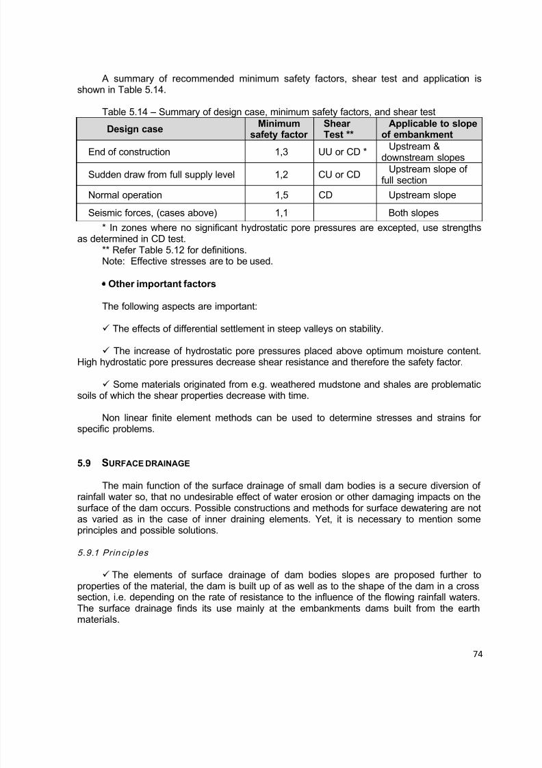
8/12/2019 ICOLD Small Dams Sept 2011
http://slidepdf.com/reader/full/icold-small-dams-sept-2011 74/149

8/12/2019 ICOLD Small Dams Sept 2011
http://slidepdf.com/reader/full/icold-small-dams-sept-2011 75/149
75
The elements for surface drainage are usually applied at dams higher than 6 m. Atlower dams, the fundamental condition of a good drainage is a good and maintained grassingover of the downstream slope or an effective and stabile fortification of the upstream slope.
For the design of the surface drainage, knowledge of the filtering environment (mutual
relations regarding the permeability of the dam and the background) is important. It isunnecessary to use the surface drainage in a case, when a permeable sandy dam is foundedupon a permeable (sandy or gravelly) and more than 3 m thick background.
At dams higher than 10 m the slopes are usually divided by berms, which in a case ofdownstream slope use to be 5 ÷ 10 m vertically from each other, are min. 1,5 m wide (better 3m) and have a longitudinal inclination 1 ÷ 2 %. The berms restrict the flow velocity of rainfallwaters on the slopes and contribute to the protection of the dam surface against the watererosion.
From the dam crest, upon which a road surface is solidificated by asphalt, blocks etc.,the rain-fall waters are drained to both abutments of the dam by a surface-water sewerage
system.
5.9.2 Poss ible Mechanical Solut io n of th e Surface Dewatering
Upon the lower part of the downstream slope and to the area of downstream toe, intoa partly digged out adjoining downstream area (ditch-shaped), it is possible to put layers ofpermeable materials in a configuration of a inverted filter (Figure 5.10).
Figure 5.10 – Configuration of a inverted filter.
By this modification the surface water will be drained into a downsloped permeableelement. The construction is suitable for earthy or earthy-sandy homogenous dams forterritories with mild winters (without a risk of freezing), with a dam height approx. to 10 m.
The formation of longitudinal strengthened open ditches, draining gravitationallythe rainfall water running upon the grassy downstream slope along the downstream toe to thechannels from outlets or from spillways. For to limit the expansion of energy of the flowingwater it is convenient to place the dewatering ditches or rills also upon the berms, as long asthe dam has them. The waters are then safely deflected into the downstream area upon aslope with a strengthened slope in the dam abutment.
In case of concerns for a local damage of the construction by a concentrated rain-fallwater at other dam types (especially made of concrete and masonry) it is possible to utilisecommon elements of a surface-water sewerage system (e.g. plumber’s downcomers etc.).

8/12/2019 ICOLD Small Dams Sept 2011
http://slidepdf.com/reader/full/icold-small-dams-sept-2011 76/149
76
The mentioned dewatering elements must be regularly maintained if a reliable functionshould be secured steadily. It is especially necessary to clean the foot ditches of fallen leaves,accumulated dry grass and of other undesirable stuff, which could restrict their function.However, due to their good accessibility in comparison with the inner dewatering systems, the
main advantage of the elements for surface drainage is their easy checking, trouble-freemaintenance and relatively easy repairs.
Other technical solutions of surface dewatering of dams are used in various countrieslocally, according to the local conditions. It is rather a question of unique constructions whichshould not be generalized.
5.10 SLOPE PROTECTION
5.10.1 Upstream Slope Protect ion
The upstream slopes of earthfill dams must be protected against destructive waveaction. In some instances, provision must be made against burrowing animals. The usualtypes of surface protection for upstream slopes are rock riprap, either dry dumped or handplaced, and concrete pavement. ICOLD Bulletin 91, published in June 1993 specifically dealswith protection of upstream slopes for fill dams and it is important to be consulted.
Other types of protection for small dams that have been used are soil cement pavement,and (on small and relatively unimportant structures) wood and sacked concrete. The upstreamslope protection should extend from the crest of the dam to a safe distance below minimumwater level (usually several feet). In some cases, it is advantageous to terminate the slopeprotection on a supporting berm, but it is generally not required.
Where the water level in the dam can be expected to fluctuate widely, or where a highdegree of protection is required, the use of a rock layer, usually called “rip-rap” is the mosteffective method of control, as illustrated in Fig. 5.11.[4]
Fig. 5.11 – Typical rip-rap layer for the protection of the upstream slope (Lewis, 2002).

8/12/2019 ICOLD Small Dams Sept 2011
http://slidepdf.com/reader/full/icold-small-dams-sept-2011 77/149
77
The supporting layer for the rip-rap is intended to protect the fill from the hydrodynamiceffects of waves and from erosion. The U.S. Corps of Engineers recommends the followingrockfill diameter (D50) and thickness of rip-par layer presented at the following table [3].
Table 5.15 – Rip-Rap layer recommended by U.S. Corps of Engineers.
Wave height(m)
Average rockfill diameter – D50 (m)
Layer thickness(m)
0 – 0.60 0.25 0.300.60 – 1.20 0.30 0.461.20 – 1.80 0.38 0.611.80 – 2.40 0.46 0.762.40 – 3.00 0.53 0.91
The same corporation recommends the following filter layer or bedding thicknessbetween the rip-rap and the earthfill.
Table 5.16 – Transition thickness layer recommend by U.S. Corps of EngineersMaximum wave height (m) Bedding thickness layer (m)
0 – 1.20 0.151.20 – 2.40 0.252.40 – 3.00 0.30
For wave height from 0.30 to 1.55 m it is also possible to use the following table, presentby the French Guidelines [5].
Table 5.17 – Dimensions of upstream rip-rap (French Guidelines on Small Dams)Wave height
(m) Thickness - e
(m) Block diameter – D50
(m) 0.30 0.30 0.200.55 0.40 0.250.80 0.50 0.301.05 0.60 0.401.30 0.70 0.451.55 0.80 0.50
The supporting layer may be replaced by a puncture-resistant geotextile in cases inwhich the fill material is fairly resistant to erosion.
5.10.2 Select ing the Type of Upstream Protect ion
Experience has shown that in most cases, dumped riprap furnishes the best upstreamslope protection at the lowest ultimate cost. Approximately 100 dams, located in varioussections of the United States with a wide variety of climate conditions and wave severity, wereexamined by the Corps of Engineers. The results of this survey were used as a basis forestablishing the most practical and economical means for slope protection. The dams werefrom 5 to 50 years old and were constructed by various agencies. This survey found that:
Dumped riprap failed in only 5 percent of the cases it was used; and failures were dueto improper size of stones.
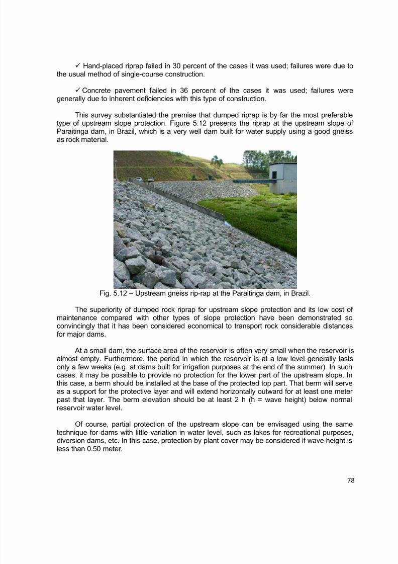
8/12/2019 ICOLD Small Dams Sept 2011
http://slidepdf.com/reader/full/icold-small-dams-sept-2011 78/149
78
Hand-placed riprap failed in 30 percent of the cases it was used; failures were due tothe usual method of single-course construction.
Concrete pavement failed in 36 percent of the cases it was used; failures were
generally due to inherent deficiencies with this type of construction.
This survey substantiated the premise that dumped riprap is by far the most preferabletype of upstream slope protection. Figure 5.12 presents the riprap at the upstream slope ofParaitinga dam, in Brazil, which is a very well dam built for water supply using a good gneissas rock material.
Fig. 5.12 – Upstream gneiss rip-rap at the Paraitinga dam, in Brazil.The superiority of dumped rock riprap for upstream slope protection and its low cost of
maintenance compared with other types of slope protection have been demonstrated soconvincingly that it has been considered economical to transport rock considerable distancesfor major dams.
At a small dam, the surface area of the reservoir is often very small when the reservoir isalmost empty. Furthermore, the period in which the reservoir is at a low level generally lastsonly a few weeks (e.g. at dams built for irrigation purposes at the end of the summer). In suchcases, it may be possible to provide no protection for the lower part of the upstream slope. Inthis case, a berm should be installed at the base of the protected top part. That berm will serveas a support for the protective layer and will extend horizontally outward for at least one meterpast that layer. The berm elevation should be at least 2 h (h = wave height) below normalreservoir water level.
Of course, partial protection of the upstream slope can be envisaged using the sametechnique for dams with little variation in water level, such as lakes for recreational purposes,diversion dams, etc. In this case, protection by plant cover may be considered if wave height isless than 0.50 meter.
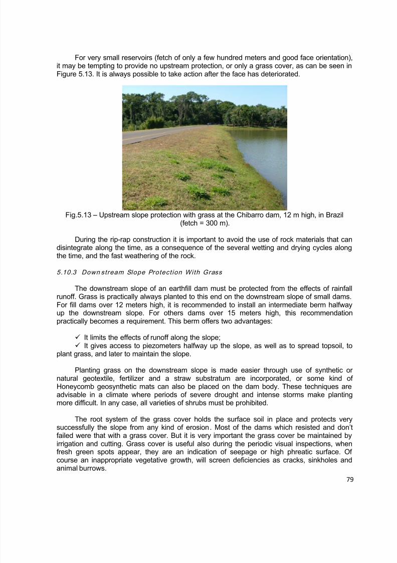
8/12/2019 ICOLD Small Dams Sept 2011
http://slidepdf.com/reader/full/icold-small-dams-sept-2011 79/149
8/12/2019 ICOLD Small Dams Sept 2011
http://slidepdf.com/reader/full/icold-small-dams-sept-2011 80/149
80
The grass cover must be maintained by irrigation and cutting. Irrigation by sprinklers isnecessary to prevent withering of the grass. For this reason grass cover is not fitted in aridregions. Grass cover is useful also during the periodic visual inspections; when fresh greenspots appear, they are an indication of seepage or high phreatic surface.
The grass must be cut from time to time to prevent high and inappropriate vegetativegrowth, which will screen deficiencies as cracks, sinkholes and animal burrows. Excessivevegetation can obscure large area of the slope and prevent good visual inspection. Problemsthat threaten the dam integrity can develop and remain undetected if they are obscured byhigh vegetation. Excessive vegetation can provide habitat for rodent and burrowing animals,which burrows are a threat to the embankment dam by causing piping.
Although grass cover is desirable as slope protection, growth of deep rooted largeshrubs and trees is undesirable. Their deep root system could shorten the seepage path,providing seepage pats and initiate piping, especially on the decaying root system whenvegetation dies.
5.10.4 Down stream Slope Protect ion With Gravel
The riprap slope protection is made up of at least two layers:
The outer layer consists of broken rock or boulders which prevent erosion.
The inner layer is the filter or bedding and could consist of one or two layers. If it isone layer it consists of a sand-gravel mixture. If it is of two layers, the inner layer is of coarsesand and the outer is of gravel. The relation between the coarseness of the grains of twoadjacent layers must be the filter rules in order to prevent the removing of material from theunderlying inner layer through the pores of the outer material. If these rules are not regarded,
the surface runoff can erode the under layer, undermine the rockfill layer, damage all thesurface protection and form gullies in the protected embankment.
The slope upon which the riprap is placed must be flat to prevent rockfill from movingdown the slope. Hand-placed rockfill, providing usually good protection, is a thin blanket. Mostmodern rockfill is dumped in place, resulting in a thicker blanket of protection. Vegetation onthe riprap must be weeded out, because it could move and replace the stones and damagethe protection.
A berm on the mid height of the slope will stop the flowing down rain water and decreaseits velocity. It will also increase the slope stability. A ditch on the interface of the berm with theslope to collect the flowing down water is very useful. The berm will also support the upper
slope protection.
5.10.5 Protect ion From Seepage Piping
The downstream slope protection of embankment dams serves to protect the slope notonly from surface erosion, but also from erosion due to inner seepage from the dam. For thisreason it is advisable the filter under the rockfill and the concrete protection to have thepossibility to avoid erosion from any uncontrolled seepage.
8/12/2019 ICOLD Small Dams Sept 2011
http://slidepdf.com/reader/full/icold-small-dams-sept-2011 81/149
81
The junction of the downstream slope with the ground surface is protected from seepageand piping with a downstream toe. It is a small rockfill zone, divided from the main dam by oneor two filter layers and acting as drain. Except of horizontal blanket drain and chimney drainwith blanket, the toe zone of rock material is a good internal drain to control seepage. Damswithout internal drains have seepage problems, because the seepage (phreatic) surface
emerges on the slope surface. The toe dam protects the dam also from tail water if any.
The part of the valley side against which the dam is built is the abutment. Surface runofffrom the abutment could cause rapid erosion on the slope-abutment interface. To avoid thisthere must be provided a concrete ditch to collect all rain surface water from the abutment andthe dam slope.
Seepage is also often coming out on the lower part of the slope-abutment interface. Thiscontact is prone to seepage because the embankment fill near the abutment is less dense andless watertight. The embankment fill near the abutments is less dense because compaction isdifficult along the interface. A toe drain is to be put on the slope-abutment interface to carry theinternal seepage water away from the dam. It must be met by filter under the slope protection
to avoid any seepage erosion.
5.11 CREST DESIGN
Placing a layer of gravel on the crest will in particular avoid the formation of ruts due totraffic and desiccation of the last layers of compacted clay materials. If the crest is notprotected, it can experience severe erosion. Crest erosion protection is usually the roadsurfacing such as gravel, concrete pavement or asphalt and depends on the amount of theanticipated traffic. If no traffic is expected, a grass cover could be enough. In designing thedam crest of a small earthfill dam the following items should be considered:
Width Drainage Camber Surfacing Safety requirements
5.11.1 Width
The crest width of an earthfill dam depends on considerations such as nature ofembankment materials and minimum allowable percolation distance through the embankmentat normal reservoir level, height and importance of structure, possible roadway requirementsand allowable materials at the site.
Because of practical difficulties in determining these factors, the crest width is, as a rule,determined empirically and largely by precedent experience. According to the Bureau ofReclamation, in the United States, the following formula is suggested for crest width for smallearthfill dams:
w = z/5 + 10
where: w = width of crest in feetz = height of dam, in feet, above the streambed.
8/12/2019 ICOLD Small Dams Sept 2011
http://slidepdf.com/reader/full/icold-small-dams-sept-2011 82/149
82
For dams with 5 to 15 m height, the following crest width are then recommended.
Table 5.18 – Crest width recommended for small dams – Bureau of Reclamation/87 [3]Dam Height (m) Crest Width (m)
5 4
10 515 6
Many successful small dams have been constructed with crest less than 6 m wide. Nodam should have a crest width of less than 3 m, because this is the minimum needed for anaccess road to permit maintenance works.
The French Guidelines for Small Dams observed that for zoned dams their width alsodepend on the number of zones at the crest. The following minimum widths are proposed,
depending on their safety parameter V H 2 :
Table 5.19 – Minimum crest widths proposed for small dams (French Guidelines) [5]
Parameter V H 2 < 100 100 to 300 > 300
L minimum 3 m 4 m 5 m
Lewis, 2002 [4] observed that the crest width increases as the height of the damincreases, and presents the following empirical formula for crest width:
Crest width (m) = H0,5 + 1
Where H is the height of the crest above the bed stream. Table 5.16 presents the Australian recommended top width for dams of various heights based on the above formula.
Table 5.20 – Crest width recommended for small dams (Lewis, 2002)Dam Height(m)
Crest Width(m)
4 3.005 3.256 3.507 3.658 3.859 4.00
In China, at the Hongshiyan homogenous dam, 12 m maximum height, in HubeiProvince, a crest width 5 m had been used, as can be seen in Fig. 5.14.
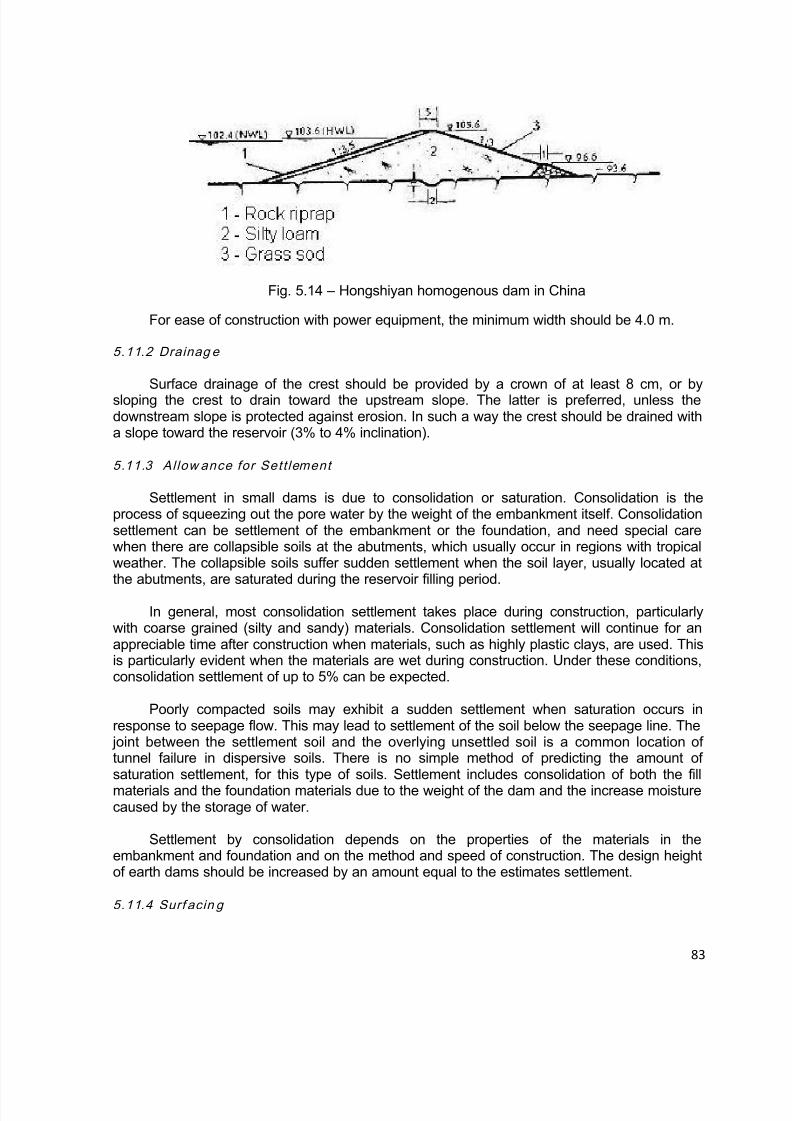
8/12/2019 ICOLD Small Dams Sept 2011
http://slidepdf.com/reader/full/icold-small-dams-sept-2011 83/149
83
Fig. 5.14 – Hongshiyan homogenous dam in China
For ease of construction with power equipment, the minimum width should be 4.0 m.
5.11.2 Drainag e
Surface drainage of the crest should be provided by a crown of at least 8 cm, or bysloping the crest to drain toward the upstream slope. The latter is preferred, unless thedownstream slope is protected against erosion. In such a way the crest should be drained witha slope toward the reservoir (3% to 4% inclination).
5.11.3 Allow ance for Sett lement
Settlement in small dams is due to consolidation or saturation. Consolidation is theprocess of squeezing out the pore water by the weight of the embankment itself. Consolidationsettlement can be settlement of the embankment or the foundation, and need special carewhen there are collapsible soils at the abutments, which usually occur in regions with tropicalweather. The collapsible soils suffer sudden settlement when the soil layer, usually located atthe abutments, are saturated during the reservoir filling period.
In general, most consolidation settlement takes place during construction, particularlywith coarse grained (silty and sandy) materials. Consolidation settlement will continue for anappreciable time after construction when materials, such as highly plastic clays, are used. Thisis particularly evident when the materials are wet during construction. Under these conditions,consolidation settlement of up to 5% can be expected.
Poorly compacted soils may exhibit a sudden settlement when saturation occurs inresponse to seepage flow. This may lead to settlement of the soil below the seepage line. The
joint between the settlement soil and the overlying unsettled soil is a common location oftunnel failure in dispersive soils. There is no simple method of predicting the amount ofsaturation settlement, for this type of soils. Settlement includes consolidation of both the fillmaterials and the foundation materials due to the weight of the dam and the increase moisturecaused by the storage of water.
Settlement by consolidation depends on the properties of the materials in theembankment and foundation and on the method and speed of construction. The design heightof earth dams should be increased by an amount equal to the estimates settlement.
5.11.4 Surf acin g
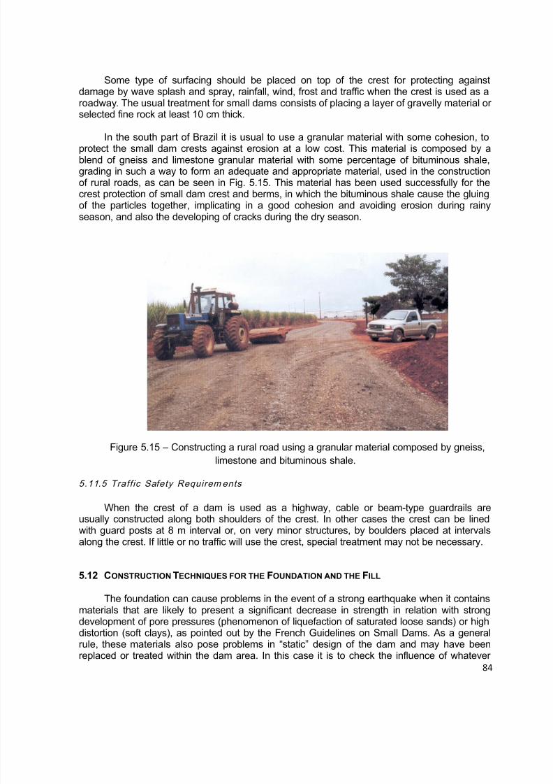
8/12/2019 ICOLD Small Dams Sept 2011
http://slidepdf.com/reader/full/icold-small-dams-sept-2011 84/149
84
Some type of surfacing should be placed on top of the crest for protecting againstdamage by wave splash and spray, rainfall, wind, frost and traffic when the crest is used as aroadway. The usual treatment for small dams consists of placing a layer of gravelly material orselected fine rock at least 10 cm thick.
In the south part of Brazil it is usual to use a granular material with some cohesion, toprotect the small dam crests against erosion at a low cost. This material is composed by ablend of gneiss and limestone granular material with some percentage of bituminous shale,grading in such a way to form an adequate and appropriate material, used in the constructionof rural roads, as can be seen in Fig. 5.15. This material has been used successfully for thecrest protection of small dam crest and berms, in which the bituminous shale cause the gluingof the particles together, implicating in a good cohesion and avoiding erosion during rainyseason, and also the developing of cracks during the dry season.
Figure 5.15 – Constructing a rural road using a granular material composed by gneiss,limestone and bituminous shale.
5.11.5 Traffic Safety Requirem ents
When the crest of a dam is used as a highway, cable or beam-type guardrails areusually constructed along both shoulders of the crest. In other cases the crest can be linedwith guard posts at 8 m interval or, on very minor structures, by boulders placed at intervalsalong the crest. If little or no traffic will use the crest, special treatment may not be necessary.
5.12 CONSTRUCTION TECHNIQUES FOR THE FOUNDATION AND THE FILL
The foundation can cause problems in the event of a strong earthquake when it containsmaterials that are likely to present a significant decrease in strength in relation with strongdevelopment of pore pressures (phenomenon of liquefaction of saturated loose sands) or highdistortion (soft clays), as pointed out by the French Guidelines on Small Dams. As a generalrule, these materials also pose problems in “static” design of the dam and may have beenreplaced or treated within the dam area. In this case it is to check the influence of whatever

8/12/2019 ICOLD Small Dams Sept 2011
http://slidepdf.com/reader/full/icold-small-dams-sept-2011 85/149

8/12/2019 ICOLD Small Dams Sept 2011
http://slidepdf.com/reader/full/icold-small-dams-sept-2011 86/149
86
APPENDIX - RECOMMENDED EMBANKMENT SLOPES FOR EARTHFILL DAMS
1. Experience of China
In China the completed earth dams are mainly of rolled-fill type, and comprise up to date
over 95% of the entire large dams. There are many causes of slope failure. The major onesare the improper control of the placement water content, the low dry density and the lowshearing strength.
Practice has shown that for a homogeneous dam of poor placement quality, suddendrawdown of reservoir level from full height to one third of the full height may easily causesliding of the upstream slope, and that the high position of phreatic line during the first filling ofthe reservoir or the saturation of the embankment by submergence after continual raining mayalso lead to sliding of the downstream slope. In some cases, the dam slopes duringconstruction or reservoir drawdown often slid along the weak layers interbedded in thefoundation.
In the Hubei Province, the dam slopes are specified within the limit as shown in Table5.21. This method provides convenience for the masses and also ensures the dam safety.
Table 5.21 – Range of embankment slopes for dams below 15 m.[1]
H o m o g e n e o s D a m s
Sand Clay Silty loam
BermUpstream
slope(from topto bottom)
Downstream slope
(from top tobottom)
BermUpstream slope(from topto bottom)
Downstream slope
(from top tobottom)
Width of
berms(m)
Nº ofBerms
Width ofberms(m)
Nº ofBerms
1.5 11:2.5
1:2.751:2.251:2.5
1:2.251:2.5
1:2.01:2.25
S l o p i n g - c o r e
E a r t h D a m s
Embankment Sloping-core and cutoff trenchBerm
Upstreamslope (from
top tobottom)
Downstream slope
(from top tobottom)
Topthickness(normalto damslope)
Bottomthickness(normalto damslope)
Bottomwidth of
foundationcutofftrench
Bottomwidth of
abutmentcutoff trench
Width of
berms(m)
Nº ofBerms
1.5 11:2.501:2.75
1:2.01:2.25
0.8 m¼ ofdam
height
¼ of damheight
¼ of damheight
E a r t h d a m s w i t h
c e n t r a l c
o r e
Dam Shell Central core and cutoff trench
BermUpstream
slope (from
top tobottom)
Downstream slope
(from top tobottom)
Top
width Slope
Bottomwidth of
foundationcutofftrench
Bottomwidth of
abutmentcutoff trench
Widt
h ofberms(m)
Nº ofBerms
1.5 11:2~1:2.25
1:2.25~1:2.50
1:1.75~1:2.0
1:2~1:2.251.5 1:0.2
¼ waterhead
½ waterhead
2. Experience of United States
•Homogeneous Dam

8/12/2019 ICOLD Small Dams Sept 2011
http://slidepdf.com/reader/full/icold-small-dams-sept-2011 87/149
87
The homogeneous dam is recommended only where the lack of free-draining materialsmake the construction of a zoned embankment uneconomical, with the further qualificationthat for storage dams the homogeneous dam must be modified to include internal drainagefacilities.
Even in the construction of a homogeneous embankment, there is likely to be somevariation in the nature of borrow material. It is important that the coarse and more perviousmaterial be placed at the outer slopes to approach, as much as possible, the advantages ofzoned embankment. It is also important to avoid segregation of the larger particles when thefill is dumped. Segregation leads to the formation of layers of much greater permeability thanthe other embankment; these layers tend to form drainage channels for percolating water andto increase the possibility of piping.
Because of the possibility of oversights during construction and of cracking, dispersivesoil, etc., as discussed previously, consideration should be given to providing an inclined filter-drain to intercept any seepage along defects in the embankment.
The recommended slopes for small homogeneous earthfill dams are shown in Table 6for detention and storage dams on stable foundations with and without rapid drawdown as adesign condition. Where more than one soil classification is shown for a set of slopes, thetable indicates that the dam can be constructed to the slopes shown by using any of the soil orcombinations thereof.
Zoned embankments
The zoned embankment dam consists of a central impervious core flanked by zones ofmaterial that are considerably more pervious. The recommended slopes for small zonedembankment dams are shown in Table 5.23. An excellent example of a zoned dam from the
1950 era is Carter Lake Dam. An excellent example of a more recent era is Ute Dam Dike.This type of embankment should always be constructed where there is a variety of soils readilyavailable because its inherent advantages lead to savings in the costs of construction. Threemajor advantages in using zoned embankments are listed below:
Steeper slopes may be used with consequent reduction in total volume ofembankment materials;
A wide variety of materials may be used;
Maximum use can be made of material excavated from the foundation, spillway,outlet works, and other appurtenant structures.
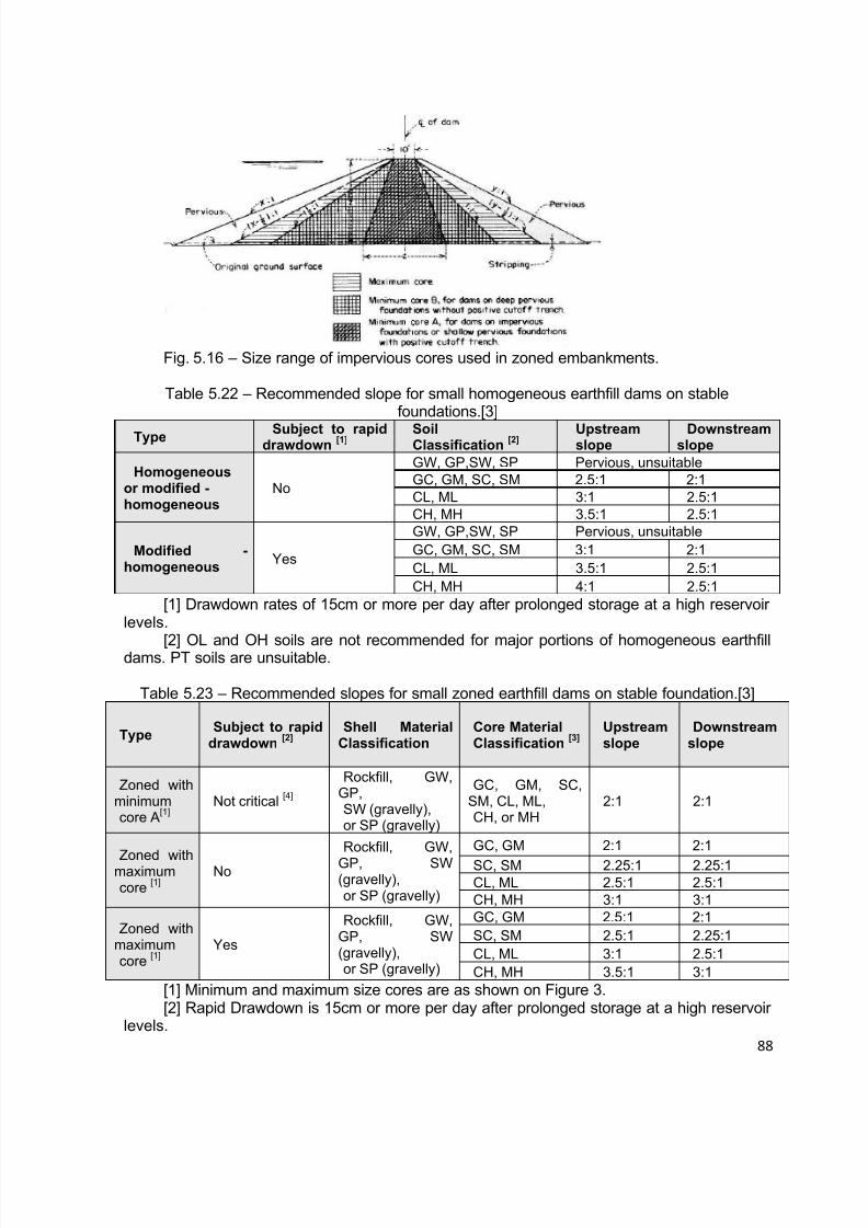
8/12/2019 ICOLD Small Dams Sept 2011
http://slidepdf.com/reader/full/icold-small-dams-sept-2011 88/149
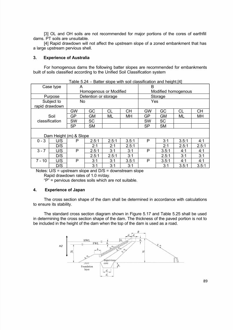
8/12/2019 ICOLD Small Dams Sept 2011
http://slidepdf.com/reader/full/icold-small-dams-sept-2011 89/149
89
[3] OL and OH soils are not recommended for major portions of the cores of earthfilldams. PT soils are unsuitable.
[4] Rapid drawdown will not affect the upstream slope of a zoned embankment that hasa large upstream pervious shell.
3. Experience of Australia
For homogenous dams the following batter slopes are recommended for embankmentsbuilt of soils classified according to the Unified Soil Classification system
Table 5.24 – Batter slope with soil classification and height.[4]Case type A
Homogenous or ModifiedBModified homogenous
Purpose Detention or storage StorageSubject to
rapid drawdownNo Yes
Soilclassification
GW GC CL CH GW GC CL CH
GP GM ML MH GP GM ML MHSW SC SW SCSP SM SP SM
Dam Height (m) & Slope0 - 3 U/S P 2.5:1 2.5:1 3.5:1 P 3:1 3.5:1 4:1
D/S 2:1 2:1 2.5:1 2:1 2.5:1 2.5:13 - 7 U/S P 2.5:1 3:1 3:1 P 3.5:1 4:1 4:1
D/S 2.5:1 2.5:1 3:1 2.5:1 3:1 3:17 - 10 U/S P 3:1 3:1 3.5:1 P 3.5:1 4:1 4:1
D/S 3:1 3:1 3:1 3:1 3.5:1 3.5:1Notes: U/S = upstream slope and D/S = downstream slope
Rapid drawdown rates of 1.0 m/day.“P” = pervious denotes soils which are not suitable.
4. Experience of Japan
The cross section shape of the dam shall be determined in accordance with calculationsto ensure its stability.
The standard cross section diagram shown in Figure 5.17 and Table 5.25 shall be usedin determining the cross section shape of the dam. The thickness of the paved portion is not tobe included in the height of the dam when the top of the dam is used as a road.
B
H H 1
HWLFWL h
1
h2
d 4 d
1
h3
b
h4
d 3
d 2
Foundationlayer
Imperviouscore
1 : n
1 : n
1 : n
1
2 3
1 : n 1
n
n n
n
1 : n
4
H2
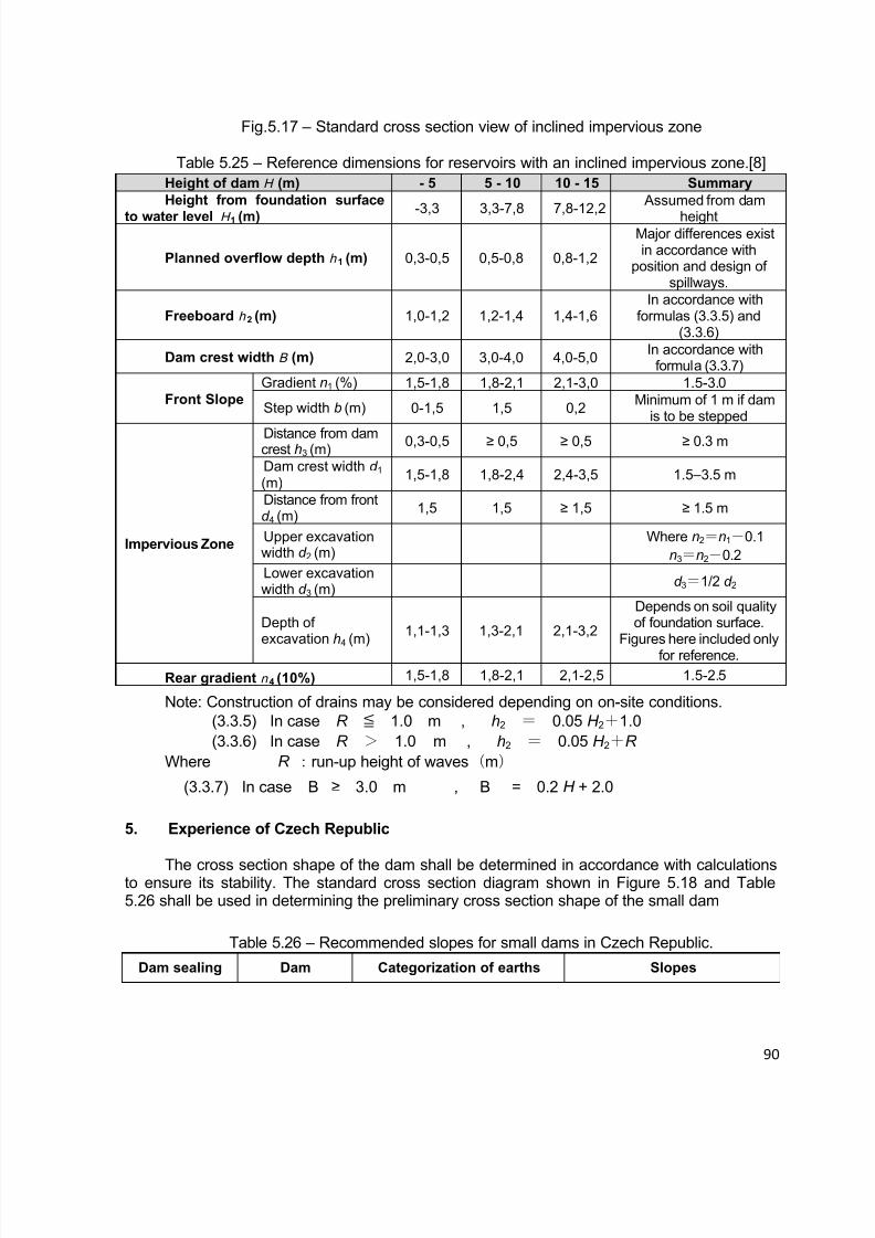
8/12/2019 ICOLD Small Dams Sept 2011
http://slidepdf.com/reader/full/icold-small-dams-sept-2011 90/149
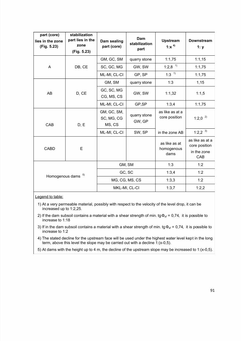
8/12/2019 ICOLD Small Dams Sept 2011
http://slidepdf.com/reader/full/icold-small-dams-sept-2011 91/149
91
part (core)
lies in the zone
(Fig. 5.23)
stabilization
part lies in the
zone
(Fig. 5.23)
Dam sealing
part (core)
Dam
stabilization
part
Upstream
1:x4)
Downstream
1: y
A DB, CEGM, GC, SM quarry stone 1:1,75 1:1,15SC, GC, MG GW, SW 1:2,8 1) 1:1,75
ML-MI, CL-CI GP, SP 1:3 1) 1:1,75
AB D, CE
GM, SM quarry stone 1:3 1,15
GC, SC, MG
CG, MS, CSGW, SW 1:1,32 1:1,5
ML-MI, CL-CI GP,SP 1:3,4 1:1,75
CAB D, E
GM, GC, SM,
SC, MG, CGMS, CS
quarry stone
GW, GP
as like as at acore position
in the zone AB
1:2,02)
ML-MI, CL-CI SW, SP 1:2,2 3)
CABD Eas like as athomogenous
dams
as like as at acore position
in the zoneCAB
Homogenous dams 5)
GM, SM 1:3 1:2
GC, SC 1:3,4 1:2
MG, CG, MS, CS 1:3,3 1:2
MKL-MI, CL-CI 1:3,7 1:2,2
Legend to table:
1) At a very permeable material, possibly with respect to the velocity of the level drop, it can beincreased up to 1:2,25.
2) If the dam subsoil contains a material with a shear strength of min. tgΦsf = 0,74, it is possible toincrease to 1:18
3) If in the dam subsoil contains a material with a shear strength of min. tgΦsf = 0,74, it is possible toincrease to 1:2
4) The stated decline for the upstream face will be used under the highest water level kept in the longterm, above this level the slope may be carried out with a decline 1:(x-0,5).
5) At dams with the height up to 4 m, the decline of the upstream slope may be increased to 1:(x-0,5).
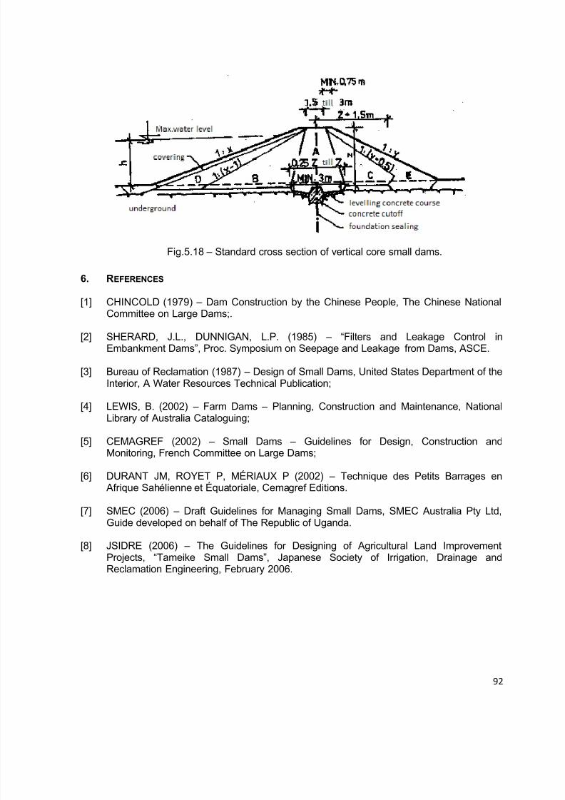
8/12/2019 ICOLD Small Dams Sept 2011
http://slidepdf.com/reader/full/icold-small-dams-sept-2011 92/149
92
Fig.5.18 – Standard cross section of vertical core small dams.
6. REFERENCES
[1] CHINCOLD (1979) – Dam Construction by the Chinese People, The Chinese NationalCommittee on Large Dams;.
[2] SHERARD, J.L., DUNNIGAN, L.P. (1985) – “Filters and Leakage Control inEmbankment Dams”, Proc. Symposium on Seepage and Leakage from Dams, ASCE.
[3] Bureau of Reclamation (1987) – Design of Small Dams, United States Department of theInterior, A Water Resources Technical Publication;
[4] LEWIS, B. (2002) – Farm Dams – Planning, Construction and Maintenance, National
Library of Australia Cataloguing;
[5] CEMAGREF (2002) – Small Dams – Guidelines for Design, Construction andMonitoring, French Committee on Large Dams;
[6] DURANT JM, ROYET P, MÉRIAUX P (2002) – Technique des Petits Barrages en Afrique Sahélienne et Équatoriale, Cemagref Editions.
[7] SMEC (2006) – Draft Guidelines for Managing Small Dams, SMEC Australia Pty Ltd,Guide developed on behalf of The Republic of Uganda.
[8] JSIDRE (2006) – The Guidelines for Designing of Agricultural Land Improvement
Projects, “Tameike Small Dams”, Japanese Society of Irrigation, Drainage andReclamation Engineering, February 2006.
8/12/2019 ICOLD Small Dams Sept 2011
http://slidepdf.com/reader/full/icold-small-dams-sept-2011 93/149
93
6. GUIDELINES ON SURVEILLANCE OF SMALL DAMS
6.1 INTRODUCTION
The owners and project engineers, who are responsible for the safe and economicoperation of dams need to be adequately informed about the following:
How to detect, measure, evaluate and remedy problems which may adversely affectsafe and economic performance of the dam, its appurtenances and equipment?
How to comply with governmental regulations pertaining to dam safety? How to integrate inspection and Dam Performance Evaluation Program activities, with
operation and maintenance of the project? What type of organization and assignment of responsibility for inspection, data
collection and reporting would be practical and effective in promoting safe and economical
project operation? What are the desired qualifications of a dam safety inspector? What should be the frequency and scope of visual inspections? When the inspection reports and monitoring data are received, how to evaluate and
analyze the data and what follow-up actions to take? What are the remedial actions which could be taken to alleviate or correct certain
problems to restore the structure to an acceptable operating condition?
6.2 SAFETY SURVEILLANCE
It is always important to a dam owner to play an important role in the dam safety
process. Frequent visits to the dam are needed to enable to observe any problem that may bedeveloping and affecting the dam safety.
If the dam fails, the dam owner are likely to be liable for any loss of life, injury ordamage which results from the accident;
Even if a failure does not cause damage outside his property, the cost of remedialwork can easily exceed the original construction cost of the dam.
A property owner who is planning to build a new dam must minimize the possibility offailure, attached liability and could also contribute to the safety of the dam by:
Having the dam designed, constructed and supervised by a qualified and experienced
professional engineer; Establishing a program of regular inspections (surveillance) and periodicmaintenance, including the keeping of appropriate records;
Monitoring conditions that may affect the safety of dams, be able to recognize thesigns of potential problems and imminent failure;
Having an experienced dam engineer investigating any unusual conditions whichcould result in total or particle failure;
Knowing what to do and who to contact when such problem appear.
8/12/2019 ICOLD Small Dams Sept 2011
http://slidepdf.com/reader/full/icold-small-dams-sept-2011 94/149
94
6.3 SURVEILLANCE PRACTICES
Safety surveillance of a dam is a program of regular visual inspection using simpleequipment and technique. It is the most economically efficient means of ensuring the long-term safety and survival of the dam. Its primary purpose is to monitor the condition and
performance of the dam and its surroundings, and to ensure maintenance before thedevelopment of potential hazards.
The procedure is unique to each dam but essentially it consists of:
Regular and close examination of the entire dam surface and its immediatesurroundings;
Appropriate measurements of cracks, surface erosion, soil transported by leakage,etc.
Keeping concise and accurate records of observations.
For continuity and consistency of approach, it is recommended that the same person
should normally carry out each type of inspection. When necessary, an experienced engineerneed to be brought in, to inspect or advice about particular problems.
To be effective, surveillance requires a good knowledge of the dam (data onconstruction, reports on all work done and inspections, etc.), and the guarantee of goodmaintenance and surveillance of any work already done. It is very important to gather allknown data about the dam concerning both its construction (surveys, design, construction, as-built documents) and its later life (operation, reports on inspections, reports on maintenancework, monitoring data, typical incidents, etc.).
The following items are useful when conducting an inspection:
Notebook or diary and pencil to write down observations about the main points; Digital camera to provide photos of the particular anomalies and deteriorations; A tape to take some measurement allowing the location of wet areas, cracks and
slumps for future comparisons.
The quality of the visual observations, and therefore dam safety can only be achieved bysufficient motivation and some technical training for the personnel involved.
6.3.1 Inspect ion Procedures
The procedure for dam safety surveillance is unique to each dam but consists essentiallyof regular, close and systematic examination of the entire surface of the dam and it immediate
surroundings. In the case of small dams, especially those dams in which owner have notsought appropriate advice, there may be a perception that above procedure are unnecessary,or an unproductive use of time. There may also be a lack of knowledge of what needs to bedone.
For a small dam it is prudent to obtain professional engineering advice to set up the firstprogram, using a simple set of pro-forma check-list to record observations.
Smaller utility companies or municipal entities that own and operate small dams may nothave in-house engineering capability and staff to form their own performance program. In such
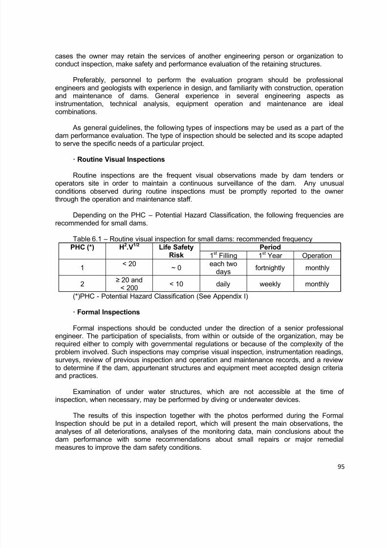
8/12/2019 ICOLD Small Dams Sept 2011
http://slidepdf.com/reader/full/icold-small-dams-sept-2011 95/149
95
cases the owner may retain the services of another engineering person or organization toconduct inspection, make safety and performance evaluation of the retaining structures.
Preferably, personnel to perform the evaluation program should be professionalengineers and geologists with experience in design, and familiarity with construction, operation
and maintenance of dams. General experience in several engineering aspects asinstrumentation, technical analysis, equipment operation and maintenance are idealcombinations.
As general guidelines, the following types of inspections may be used as a part of thedam performance evaluation. The type of inspection should be selected and its scope adaptedto serve the specific needs of a particular project.
· Routine Visual Inspections
Routine inspections are the frequent visual observations made by dam tenders oroperators site in order to maintain a continuous surveillance of the dam. Any unusual
conditions observed during routine inspections must be promptly reported to the ownerthrough the operation and maintenance staff.
Depending on the PHC – Potential Hazard Classification, the following frequencies arerecommended for small dams.
Table 6.1 – Routine visual inspection for small dams: recommended frequencyPHC (*) H2.V1/2 Life Safety
RiskPeriod
1st Filling 1st Year Operation
1< 20
~ 0each two
daysfortnightly monthly
2≥ 20 and
< 200< 10 daily weekly monthly
(*)PHC - Potential Hazard Classification (See Appendix I)
· Formal Inspections
Formal inspections should be conducted under the direction of a senior professionalengineer. The participation of specialists, from within or outside of the organization, may berequired either to comply with governmental regulations or because of the complexity of theproblem involved. Such inspections may comprise visual inspection, instrumentation readings,surveys, review of previous inspection and operation and maintenance records, and a reviewto determine if the dam, appurtenant structures and equipment meet accepted design criteriaand practices.
Examination of under water structures, which are not accessible at the time ofinspection, when necessary, may be performed by diving or underwater devices.
The results of this inspection together with the photos performed during the FormalInspection should be put in a detailed report, which will present the main observations, theanalyses of all deteriorations, analyses of the monitoring data, main conclusions about thedam performance with some recommendations about small repairs or major remedialmeasures to improve the dam safety conditions.
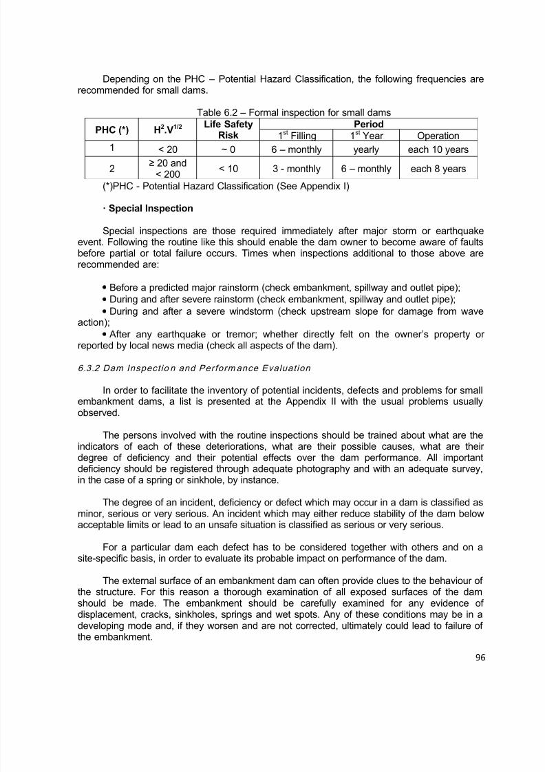
8/12/2019 ICOLD Small Dams Sept 2011
http://slidepdf.com/reader/full/icold-small-dams-sept-2011 96/149

8/12/2019 ICOLD Small Dams Sept 2011
http://slidepdf.com/reader/full/icold-small-dams-sept-2011 97/149
97
Surface displacement on an embankment often can be detected by visual examination.Sighting along the line of embankment roads, parapet walls, utility lines, guardrails,longitudinal conduits, or other lineaments parallel or concentric to the embankment axis cansometimes identify surface movements of the embankment. The crest should be examined for
depressions and crack patterns that could indicate sliding settlement, or bulging movements.The upstream and downstream slopes and areas downstream of the embankment should beexamined for any sign of bulging, depression, or other variance from smooth, uniform faceplanes.
Cracks on the surface of an embankment can be indicative of potentially unsafeconditions. Surface cracks are often caused by desiccation and shrinkage of materials nearthe surface of the embankment; however, the depth and orientation of the cracks should bedetermined for a better understanding of their cause. Openings or escarpments on theembankment crest or slopes can identity slides and a close examination of these areas shouldbe made to outline the location and extent of the slide mass. Surface cracks near theembankment abutment contact, and contacts with other structures can be an indication of
settlement of the embankment and, if severe enough, a path for seepage can develop alongthe contact. Therefore, these locations must be thoroughly examined. Cracks can also indicatedifferential settlement between embankment zones.
The downstream face and toe of the dam areas downstream of the embankment, andnatural abutment should be examined for wet spots, boils, depressions, sinkholes, or springswhich may indicate concentrated or excessive seepage through the dam and abutment.
Drainage systems should be inspected for increased or decreased flow and for anyobstructions which could plug the drains. In addition to verifying anticipated embankment andfoundation performance, instrumentation also can be an indicator of developing unsafeconditions.
6.3.3 Inspect io ns A fter Earthqu akes
If an earthquake is observed at or near a dam, or one has been reported to haveoccurred, with a Richter magnitude greater than and within a radial distance as set out in thetable below, a detailed visual inspection of the dam have to be performed, according to theICOLD Bulletin 62, in revision at 2009, according to the following list:
Richter Magnitude Distance to Dam> 4.0 ≤ 25 km > 5.0 ≤ 50 km > 6.0 ≤ 80 km
> 7.0 ≤ 125 km> 8.0 ≤ 200 km
Note: these combinations have been chosen such that a significant intensity level isexpected to have been experienced at the dam site. An alternative trigger for inspection couldfor example be an intensity of shaking of greater than MMI 4 experienced at a dam site.

8/12/2019 ICOLD Small Dams Sept 2011
http://slidepdf.com/reader/full/icold-small-dams-sept-2011 98/149
98
6.4 MONITORING S YSTEM
The present chapter only looks at aspects related to the design of a monitoring systemfor small earthfill and rockfill dams, both new constructions and operating dams with no suchsystem.
However, it must always be remembered that visual inspection is as important as themonitoring system as part of dam surveillance: that is often the means to detect problems andanomalies that affect the dam. Monitoring is the quantitative method based on the use ofmeasuring instruments, selected and positioned to give information on how the dam behaviorchanges. The monitoring system must therefore be designed according to the type, thedimensions and the specific technical features of the dam and its foundation.
For small dams, the monitoring system should consist of simple, robust and easy toinstall instruments.
6.4.1 Monito r ing Instrum ents for Small Dams
Surveillance of a small dam is essentially intended to reveal, and if possible prevent anydeterioration, in order to keep the structure in good condition for safety and also apt to fulfill itsfunctions.
Monitoring should provide the means to detect anomalies, and evaluate how fast areoccurring and how they will probably end. The monitoring data will be very useful, helping theengineer or entity responsible for the dam to decide on the nature and urgency of the requiredremedial measures.
Reservoir Water Level
This measurement helps in meeting three objectives:
Improving reservoir management through continuous knowledge of the volumes ofwater that are available;
Participating in dam monitoring by allowing examination of the influence of reservoirwater level on measurements taken by certain instruments (in particular flows and upliftpressures);
Enriching hydrological data trough measurement of flood flows.
Leakage Measurement
Monitoring of seepage - both visually for any cloudiness or fines in the seepage water,
and for unusual changes in flow rates – is the most common method used to detect for internalerosion and piping. Seepage rate is monitored by several methods, ranging from simple tomore technically complex. Some examples include:
collect seepage emerging from a toe drain or other collector pipe with a calibratedcatch container (bucket) and time the fill rate with a stopwatch (Fig. 6.1),
Parshall or other types of flumes installed in seepage collection trenches or manholesWeirs installed in open channels (Fig. 6.2).

8/12/2019 ICOLD Small Dams Sept 2011
http://slidepdf.com/reader/full/icold-small-dams-sept-2011 99/149
99
Fig. 6.1 – Leakage measurement using a vessel and a chronometer.
Fig. 6.2 – Leakage measurement using a triangular weir gauge.
Comparing the turbidity, temperature and water quality of the seepage water with the
reservoir water are potentially useful indicators of potential problems developing. Sedimenttraps built in conjunction with manholes and weirs will facilitate visual observations, and can beused to collect samples for chemical analyses. A large increase in turbidity, for example,could indicate internal erosion is occurring.
These systems are installed on new dams at the outlet from drainage elements and onoperating dams in areas where leakage is observed. Every effort must be made to ensure thatthe point of measurement collects all leakage flows, as well as possible, with no flow aroundthe measuring point and, if possible, free of any influence of rainfall.
Weirs must be kept clean and the approach channels to weirs must be regularly clearedof any material deposited or floating one (Fig. 6.3). If granular materials are observed, a
specialized engineering firm should be alerted in order to study whether there is any risk ofinternal erosion.
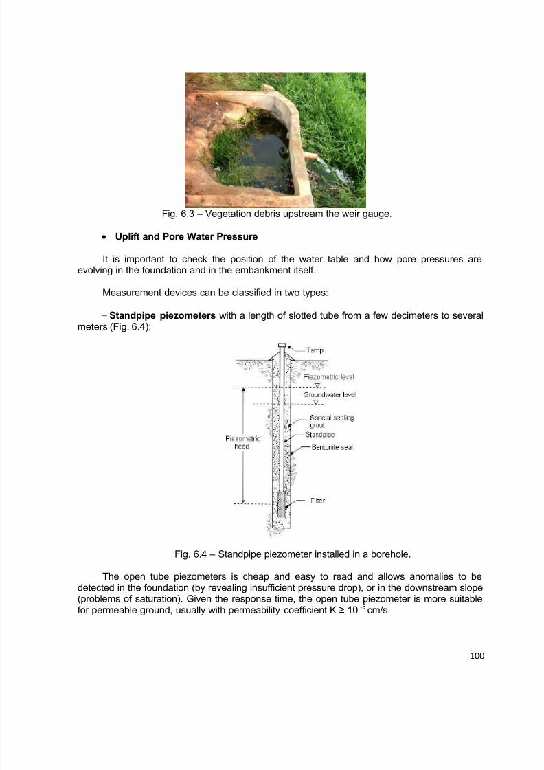
8/12/2019 ICOLD Small Dams Sept 2011
http://slidepdf.com/reader/full/icold-small-dams-sept-2011 100/149
100
Fig. 6.3 – Vegetation debris upstream the weir gauge.
Uplift and Pore Water Pressure
It is important to check the position of the water table and how pore pressures are
evolving in the foundation and in the embankment itself.
Measurement devices can be classified in two types:
Standpipe piezometers with a length of slotted tube from a few decimeters to severalmeters (Fig. 6.4);
Fig. 6.4 – Standpipe piezometer installed in a borehole.
The open tube piezometers is cheap and easy to read and allows anomalies to bedetected in the foundation (by revealing insufficient pressure drop), or in the downstream slope(problems of saturation). Given the response time, the open tube piezometer is more suitablefor permeable ground, usually with permeability coefficient K ≥ 10 -5 cm/s.

8/12/2019 ICOLD Small Dams Sept 2011
http://slidepdf.com/reader/full/icold-small-dams-sept-2011 101/149
101
Water Level Sounder - Details of the water level sounder are shown on Fig. 6.5 and6.6. This device is comprised of a suitable length of ¼ inch coaxial cable or tape, fitted at theends to contact the water surface in the plastic riser tube and for connection to an ohmmeter.
Fig. 6.5 – Water level sounder for standpipe piezometers.
Pore pressure cells give precise localized measurement and offer faster responsetimes than standpipe piezometers.
Fig. 6.6 – Different models of vibrating wire piezometers.
The vibrating wire piezometers has usually a thick-wallet stainless steel housing toprevent the vibrating wire transducer from responding to total stresses acting on the housing, avery robust and water-blocked signal cable, heavy-duty seals, and long high air entry filters.
They are good instruments to measure the pore water pressures at the foundation or at theearth embankment with permeability coefficient equal or lower than 10-6 cm/s, for long-termsurvivability, usually about 30 years.
Displacement Measurement
Measurement of the absolute displacements of the dam’s survey targets with respect tofixed benchmarks (Fig. 6.7) set up in zones that are not likely to be affected by any significantmovement; altimetric measurements (settlement) and planimetric measurements (upstream-
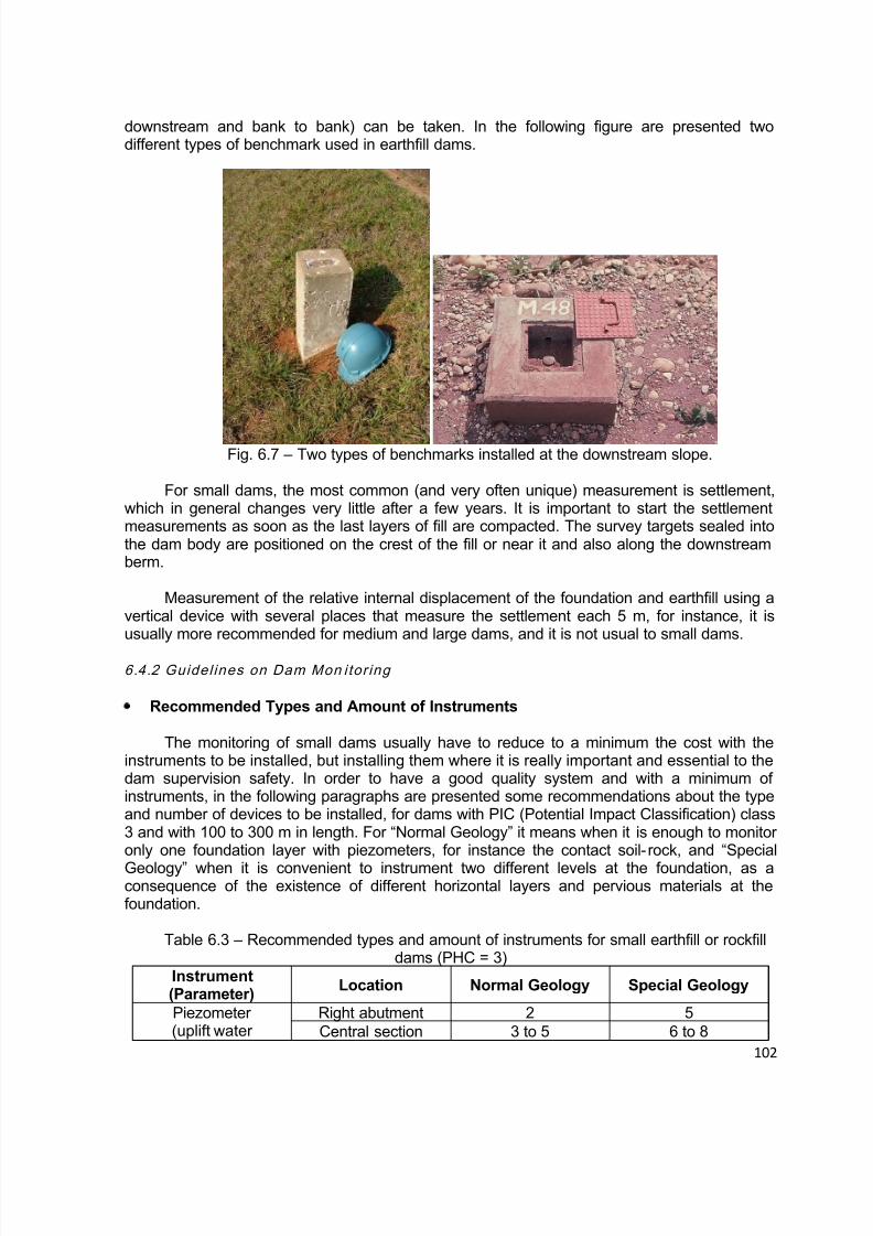
8/12/2019 ICOLD Small Dams Sept 2011
http://slidepdf.com/reader/full/icold-small-dams-sept-2011 102/149
102
downstream and bank to bank) can be taken. In the following figure are presented twodifferent types of benchmark used in earthfill dams.
Fig. 6.7 – Two types of benchmarks installed at the downstream slope.
For small dams, the most common (and very often unique) measurement is settlement,which in general changes very little after a few years. It is important to start the settlementmeasurements as soon as the last layers of fill are compacted. The survey targets sealed intothe dam body are positioned on the crest of the fill or near it and also along the downstreamberm.
Measurement of the relative internal displacement of the foundation and earthfill using avertical device with several places that measure the settlement each 5 m, for instance, it isusually more recommended for medium and large dams, and it is not usual to small dams.
6.4.2 Guidel ines on Dam Mon itor ing
Recommended Types and Amount of Instruments
The monitoring of small dams usually have to reduce to a minimum the cost with theinstruments to be installed, but installing them where it is really important and essential to thedam supervision safety. In order to have a good quality system and with a minimum ofinstruments, in the following paragraphs are presented some recommendations about the typeand number of devices to be installed, for dams with PIC (Potential Impact Classification) class3 and with 100 to 300 m in length. For “Normal Geology” it means when it is enough to monitoronly one foundation layer with piezometers, for instance the contact soil-rock, and “Special
Geology” when it is convenient to instrument two different levels at the foundation, as aconsequence of the existence of different horizontal layers and pervious materials at thefoundation.
Table 6.3 – Recommended types and amount of instruments for small earthfill or rockfilldams (PHC = 3)
Instrument(Parameter)
Location Normal Geology Special Geology
Piezometer(uplift water
Right abutment 2 5Central section 3 to 5 6 to 8

8/12/2019 ICOLD Small Dams Sept 2011
http://slidepdf.com/reader/full/icold-small-dams-sept-2011 103/149
103
pressure) Left abutment 2 5Weir gauge
(seepage water)Right abutment - 1Central section 2 2Left abutment - 1
Bench marks
(Displacements)
Crest Lc/50 Lc/20
Berm (eventual) Lb/50 Lb/20(*) Obs. Lc and Lb correspond to the length of the crest and the downstream berm in
meters.
It is important to point out that the total amount of instruments recommended in this tableis the minimum, and in the case of dams with foundations deserving special attention, with anintricate geology incorporating faults and folds directly under the dam, it is important to installsome more instruments.
Considering that for small dams there are usually small support for their monitoringmaintenance it is recommended to install standpipe piezometers, if possible, which normallypresent a performance compatible with that of the dam itself. These instruments can be
successfully installed in soils with a permeability coefficient higher or equal to 10 -6 cm/s, asalready discussed. It is also important to install one or more weir gauge to monitor theleakage.
Recommendations for Piezometer Measurements
In the location of the piezometers at the dam foundation, impervious core or horizontalfilter, the following recommendations are important to be attended:
To install foundation piezometers upstream and downstream of the grout curtain orthe cutoff trench, in order to calculate its performance;
Perform the installation of a piezometer at the upstream drain blanket, in order toknow the water head at the drainage system;
In dams with PHC = 3 install some piezometers at the central core, near the axis ofthe dam, to evaluate the maximum pore pressures and the phreatic line location;
If the geological investigations showed a fault crossing the foundation from upstreamto downstream it is very important to install some foundation piezometers along this fault,which usually implies in a preferential seepage way.
In the following sketch and expressions are presented the location of a grout curtain orthe cutoff trench at the foundation of an earthfill dam, and how it is possible to calculate its
efficiency considering the water head drop.
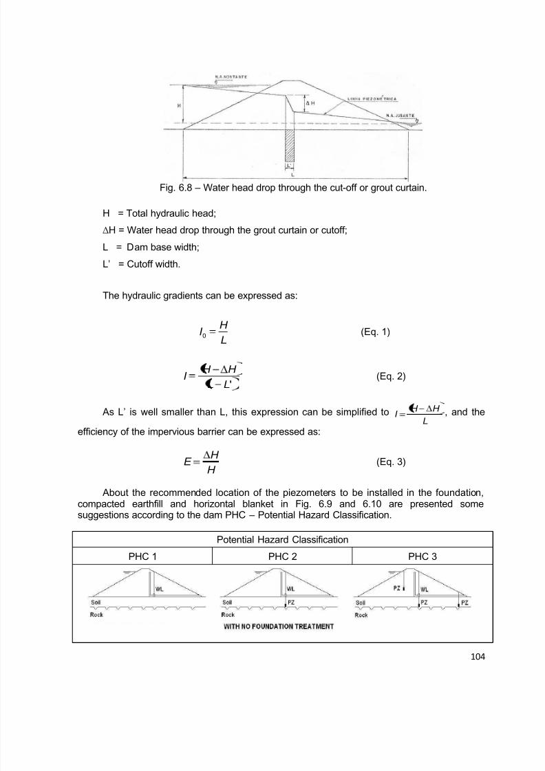
8/12/2019 ICOLD Small Dams Sept 2011
http://slidepdf.com/reader/full/icold-small-dams-sept-2011 104/149

8/12/2019 ICOLD Small Dams Sept 2011
http://slidepdf.com/reader/full/icold-small-dams-sept-2011 105/149
105
Fig. 6.9 – Recommended standpipe piezometer location for small earthfill damsaccording the PHC.
Potential Hazard Classification PHC 1 PHC 2 PHC 3
Fig. 6.10 – Recommended piezometer location for small rockfill dams according to thePHC.
In Figure 6.9, some piezometers have their chamber located in the horizontal drain. Thatallows controlling efficiency of the drainage system and measuring hydraulic gradient insidethe horizontal drain. Another solution is to have piezometers not reaching the drain, with thechamber inside the downstream embankment. That allows measuring piezometry in the
embankment and, indirectly, controlling the efficiency of the drainage system.
Recommendations for Leakage Measurements
During the design of the dam and the internal drained system it is important to considerhow the seepage water will be measured, because sometime it is important to incorporatesome especial details at the horizontal blanket, in order to allow a more precise monitoringsystem. At the small dams it is usually recommendable installing a triangular weir gauge at thedownstream toe, at the central section of the dam, when possible, as illustrated in Fig. 6.11
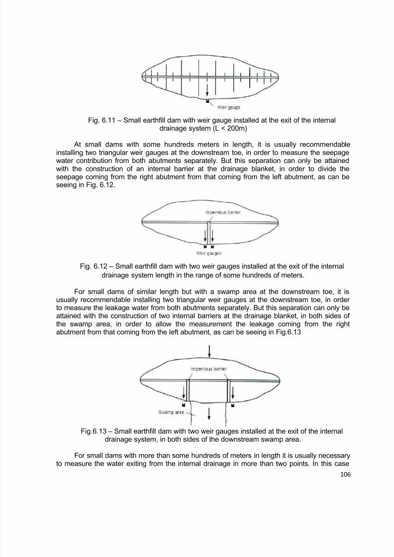
8/12/2019 ICOLD Small Dams Sept 2011
http://slidepdf.com/reader/full/icold-small-dams-sept-2011 106/149
106
Fig. 6.11 – Small earthfill dam with weir gauge installed at the exit of the internaldrainage system (L < 200m)
At small dams with some hundreds meters in length, it is usually recommendableinstalling two triangular weir gauges at the downstream toe, in order to measure the seepagewater contribution from both abutments separately. But this separation can only be attainedwith the construction of an internal barrier at the drainage blanket, in order to divide theseepage coming from the right abutment from that coming from the left abutment, as can beseeing in Fig. 6.12.
Fig. 6.12 – Small earthfill dam with two weir gauges installed at the exit of the internaldrainage system length in the range of some hundreds of meters.
For small dams of similar length but with a swamp area at the downstream toe, it isusually recommendable installing two triangular weir gauges at the downstream toe, in orderto measure the leakage water from both abutments separately. But this separation can only beattained with the construction of two internal barriers at the drainage blanket, in both sides ofthe swamp area, in order to allow the measurement the leakage coming from the rightabutment from that coming from the left abutment, as can be seeing in Fig.6.13
Fig.6.13 – Small earthfill dam with two weir gauges installed at the exit of the internaldrainage system, in both sides of the downstream swamp area.
For small dams with more than some hundreds of meters in length it is usually necessaryto measure the water exiting from the internal drainage in more than two points. In this case

8/12/2019 ICOLD Small Dams Sept 2011
http://slidepdf.com/reader/full/icold-small-dams-sept-2011 107/149
107
the others weir gauges need to be installed at the lower points of the foundation, along thelongitudinal section, in which there are the possibility of water leakage, after the reservoirfilling. Usually it is not possible to evaluate correctly all the places in which it will have water atthe dam toe previously, then it is recommended to install the weir gauges of the central sectionbefore the reservoir filling, and the other during or after the reservoir filling.
6.4.3 Data Analysis an d Report in g
Data management and analysis are fundamental to understanding the behavior of themonitored dam, for detecting unsafe development, and for determining the performance of theinstrument system. The plan should indicate the frequency of data collection, the extent andtimeliness of processing, the level of analysis and the reporting requirements.
Data Management
The management of data consists of data collection, reduction and processing, andreporting. Data collection should begin with a well-defined established schedule. Data
collection procedures should adhere to the following guidelines:
Data will be most consistent if collected by the same person;
Using the same device or readout unit to read an instrument every time give the mostconsistent readings;
Instrumentation data should include the instrument reading and also any informationthat identifies the project, instrument, reader, date, visual observations, climate, remarks, andany site conditions that might affect the value of the reading;
Recording reading in field books allows for comparison of current readings with
previous readings at the time the readings are collected. The readings in field books should betransferred to data sheets or computer files as soon as possible after being obtained;
Readings that exceed established levels should be reported immediately. The firstaction should be to control the condition of the measuring device and to perform a newmeasurement. If the measurement is confirmed, appropriate personnel should be notifiedbecause a change in instrument reading or in visual observation reveals that a problem ordangerous situation has occurred, or is occurring.
Data processing and reduction consists of converting the raw data into meaningfulengineering parameters necessary for graphical presentation, analysis and interpretation.Calibration constants may be needed to convert the field reading to engineering values.
Checking for errors in instrumentation data should be accomplished at each level ofcollection and processing, from reading of instruments in the field to final interpretation of theinstrumentation data. Instrumentation readings should be compared with ranges specified bythe design office and with previous readings under similar conditions. Conformance withprevious established trends should be determined.
Data Presentation – Numerically tabulated data are not conducive to detectingtrends, evaluating unanticipated behavior, and comparison with design values. Plots of thedata are needed to provide visual comparisons between actual and predicted behavior, a
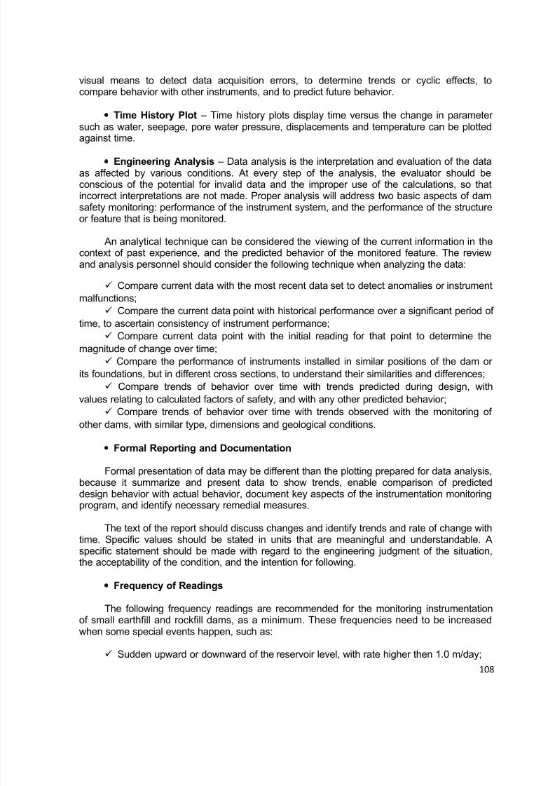
8/12/2019 ICOLD Small Dams Sept 2011
http://slidepdf.com/reader/full/icold-small-dams-sept-2011 108/149
108
visual means to detect data acquisition errors, to determine trends or cyclic effects, tocompare behavior with other instruments, and to predict future behavior.
Time History Plot – Time history plots display time versus the change in parametersuch as water, seepage, pore water pressure, displacements and temperature can be plotted
against time.
Engineering Analysis – Data analysis is the interpretation and evaluation of the dataas affected by various conditions. At every step of the analysis, the evaluator should beconscious of the potential for invalid data and the improper use of the calculations, so thatincorrect interpretations are not made. Proper analysis will address two basic aspects of damsafety monitoring: performance of the instrument system, and the performance of the structureor feature that is being monitored.
An analytical technique can be considered the viewing of the current information in thecontext of past experience, and the predicted behavior of the monitored feature. The reviewand analysis personnel should consider the following technique when analyzing the data:
Compare current data with the most recent data set to detect anomalies or instrumentmalfunctions;
Compare the current data point with historical performance over a significant period oftime, to ascertain consistency of instrument performance;
Compare current data point with the initial reading for that point to determine themagnitude of change over time;
Compare the performance of instruments installed in similar positions of the dam orits foundations, but in different cross sections, to understand their similarities and differences;
Compare trends of behavior over time with trends predicted during design, withvalues relating to calculated factors of safety, and with any other predicted behavior;
Compare trends of behavior over time with trends observed with the monitoring ofother dams, with similar type, dimensions and geological conditions.
Formal Reporting and Documentation
Formal presentation of data may be different than the plotting prepared for data analysis,because it summarize and present data to show trends, enable comparison of predicteddesign behavior with actual behavior, document key aspects of the instrumentation monitoringprogram, and identify necessary remedial measures.
The text of the report should discuss changes and identify trends and rate of change withtime. Specific values should be stated in units that are meaningful and understandable. A
specific statement should be made with regard to the engineering judgment of the situation,the acceptability of the condition, and the intention for following.
Frequency of Readings
The following frequency readings are recommended for the monitoring instrumentationof small earthfill and rockfill dams, as a minimum. These frequencies need to be increasedwhen some special events happen, such as:
Sudden upward or downward of the reservoir level, with rate higher then 1.0 m/day;
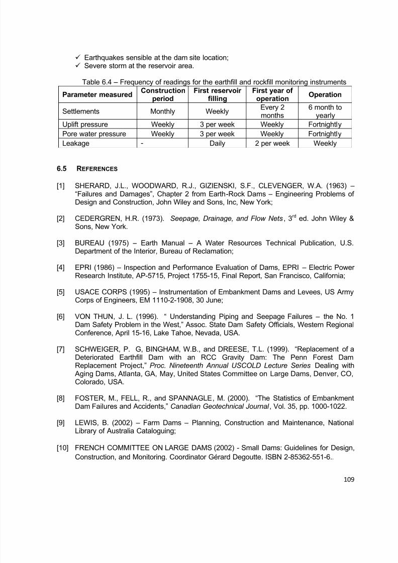
8/12/2019 ICOLD Small Dams Sept 2011
http://slidepdf.com/reader/full/icold-small-dams-sept-2011 109/149
109
Earthquakes sensible at the dam site location; Severe storm at the reservoir area.
Table 6.4 – Frequency of readings for the earthfill and rockfill monitoring instruments
Parameter measuredConstruction
period
First reservoir
filling
First year of
operationOperation
Settlements Monthly WeeklyEvery 2months
6 month toyearly
Uplift pressure Weekly 3 per week Weekly FortnightlyPore water pressure Weekly 3 per week Weekly FortnightlyLeakage - Daily 2 per week Weekly
6.5 REFERENCES
[1] SHERARD, J.L., WOODWARD, R.J., GIZIENSKI, S.F., CLEVENGER, W.A. (1963) –
“Failures and Damages”, Chapter 2 from Earth-Rock Dams – Engineering Problems ofDesign and Construction, John Wiley and Sons, Inc, New York;
[2] CEDERGREN, H.R. (1973). Seepage, Drainage, and Flow Nets, 3rd ed. John Wiley &Sons, New York.
[3] BUREAU (1975) – Earth Manual – A Water Resources Technical Publication, U.S.Department of the Interior, Bureau of Reclamation;
[4] EPRI (1986) – Inspection and Performance Evaluation of Dams, EPRI – Electric PowerResearch Institute, AP-5715, Project 1755-15, Final Report, San Francisco, California;
[5] USACE CORPS (1995) – Instrumentation of Embankment Dams and Levees, US ArmyCorps of Engineers, EM 1110-2-1908, 30 June;
[6] VON THUN, J. L. (1996). “ Understanding Piping and Seepage Failures – the No. 1Dam Safety Problem in the West,” Assoc. State Dam Safety Officials, Western RegionalConference, April 15-16, Lake Tahoe, Nevada, USA.
[7] SCHWEIGER, P. G, BINGHAM, W.B., and DREESE, T.L. (1999). “Replacement of aDeteriorated Earthfill Dam with an RCC Gravity Dam: The Penn Forest DamReplacement Project,” Proc. Nineteenth Annual USCOLD Lecture Series Dealing with
Aging Dams, Atlanta, GA, May, United States Committee on Large Dams, Denver, CO,Colorado, USA.
[8] FOSTER, M., FELL, R., and SPANNAGLE, M. (2000). “The Statistics of EmbankmentDam Failures and Accidents,” Canadian Geotechnical Journal , Vol. 35, pp. 1000-1022.
[9] LEWIS, B. (2002) – Farm Dams – Planning, Construction and Maintenance, NationalLibrary of Australia Cataloguing;
[10] FRENCH COMMITTEE ON LARGE DAMS (2002) - Small Dams: Guidelines for Design,Construction, and Monitoring. Coordinator Gérard Degoutte. ISBN 2-85362-551-6..

8/12/2019 ICOLD Small Dams Sept 2011
http://slidepdf.com/reader/full/icold-small-dams-sept-2011 110/149
110
[11] DURAND J.M., ROYET P, MERIAUX P (2002) – Technique des Petits Barrages en Afrique Sahélienne et Équatoriale, Cemagref Editions;
[12] FELL, R., C.F. WAN, CYGANIEWICZ, J., and FOSTER, M. (2003). “Time for
Development of Internal Erosion and Piping in Embankment Dams,” Journal ofGeotechnical and Geoenvironmental Engineering, Vol. 129, No. 5, April, pp. 301-315.
[13] MCCOOK, D. (2005). “A Comprehensive Discussion of Piping and Internal ErosionFailure Mechanisms,” Proc. Assoc. State Dam Safety Officials, Annual Meeting , Sept 26-30, Phoenix, Arizona, USA.
[14] SMEC (2006) – Draft Guidelines for Managing Small Dams, SMEC Australia Pty Ltd,Guide developed on behalf of The Republic of Uganda;
[15] ROYET P.(2006) – La Surveillance et l’Entretien des Petits Barrages.
[16] CSN 752410 (1997) – Standards for Small Dams Sesign, Construction, Operation andReconstruction, in Czech Republic.
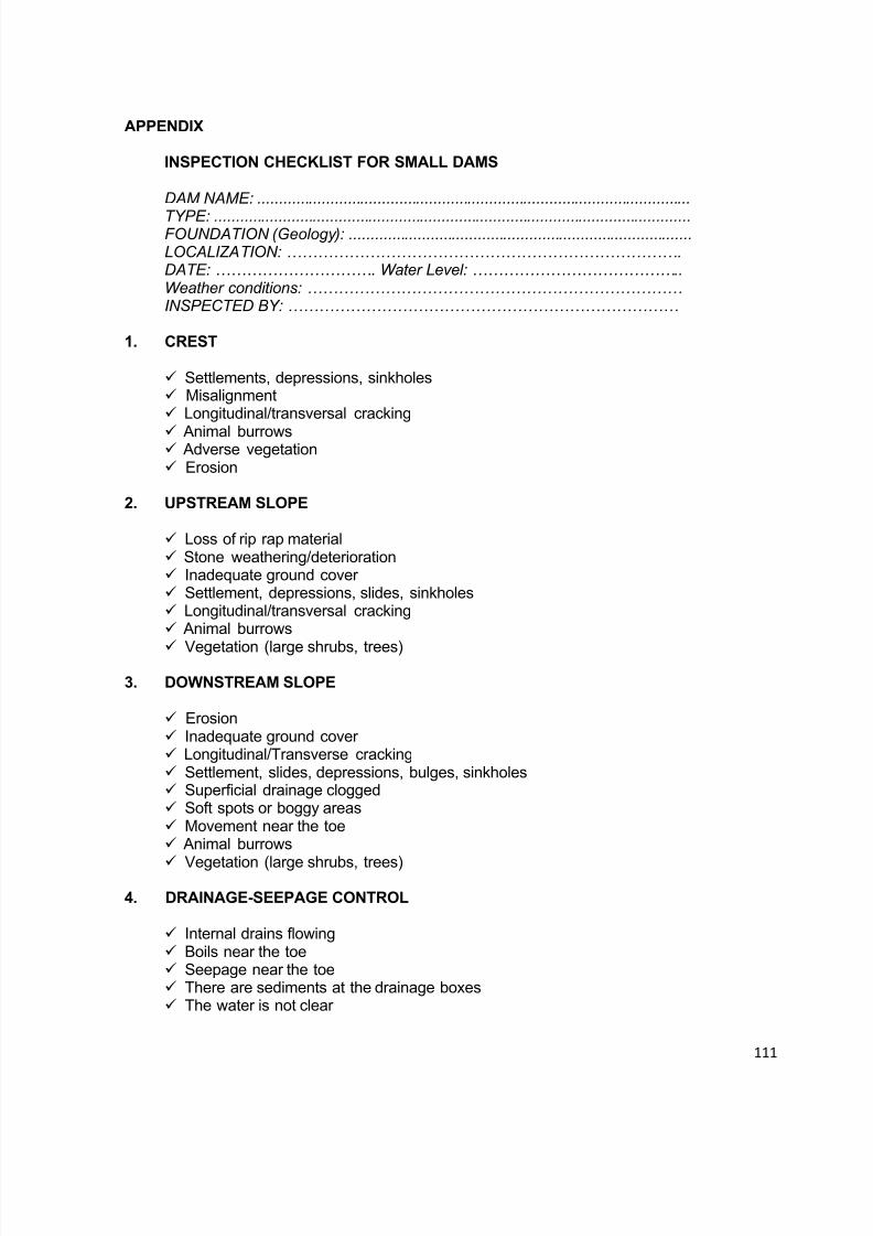
8/12/2019 ICOLD Small Dams Sept 2011
http://slidepdf.com/reader/full/icold-small-dams-sept-2011 111/149
111
APPENDIX
INSPECTION CHECKLIST FOR SMALL DAMS
DAM NAME: .....................................................................................................
TYPE: ...............................................................................................................FOUNDATION (Geology): ................................................................................LOCALIZATION: …………………………………………………………………. DATE: …………………………. Water Level: …………………………………..Weather conditions: ……………………………………………………………… INSPECTED BY: …………………………………………………………………
1. CREST
Settlements, depressions, sinkholes Misalignment Longitudinal/transversal cracking
Animal burrows Adverse vegetation Erosion
2. UPSTREAM SLOPE
Loss of rip rap material Stone weathering/deterioration Inadequate ground cover Settlement, depressions, slides, sinkholes Longitudinal/transversal cracking Animal burrows
Vegetation (large shrubs, trees)
3. DOWNSTREAM SLOPE
Erosion Inadequate ground cover Longitudinal/Transverse cracking Settlement, slides, depressions, bulges, sinkholes Superficial drainage clogged Soft spots or boggy areas Movement near the toe Animal burrows
Vegetation (large shrubs, trees)
4. DRAINAGE-SEEPAGE CONTROL
Internal drains flowing Boils near the toe Seepage near the toe There are sediments at the drainage boxes The water is not clear

8/12/2019 ICOLD Small Dams Sept 2011
http://slidepdf.com/reader/full/icold-small-dams-sept-2011 112/149

8/12/2019 ICOLD Small Dams Sept 2011
http://slidepdf.com/reader/full/icold-small-dams-sept-2011 113/149
113
Exposed reinforcement The conduit joints show:
Displacement or offsetLoss of joint materialLeakage
Are the trash racks:Broken or bentCorroded or rustedObstructed
Each of these deterioration possibilities need to be addressed in terms of:
( ) Not applicable( ) No( ) Yes( ) Need to be monitored( ) Need to be investigated( ) Need to be repaired( ) Need to be registered
Observation: All important deteriorations need to be registered with one or morephotographs taken during the inspection.
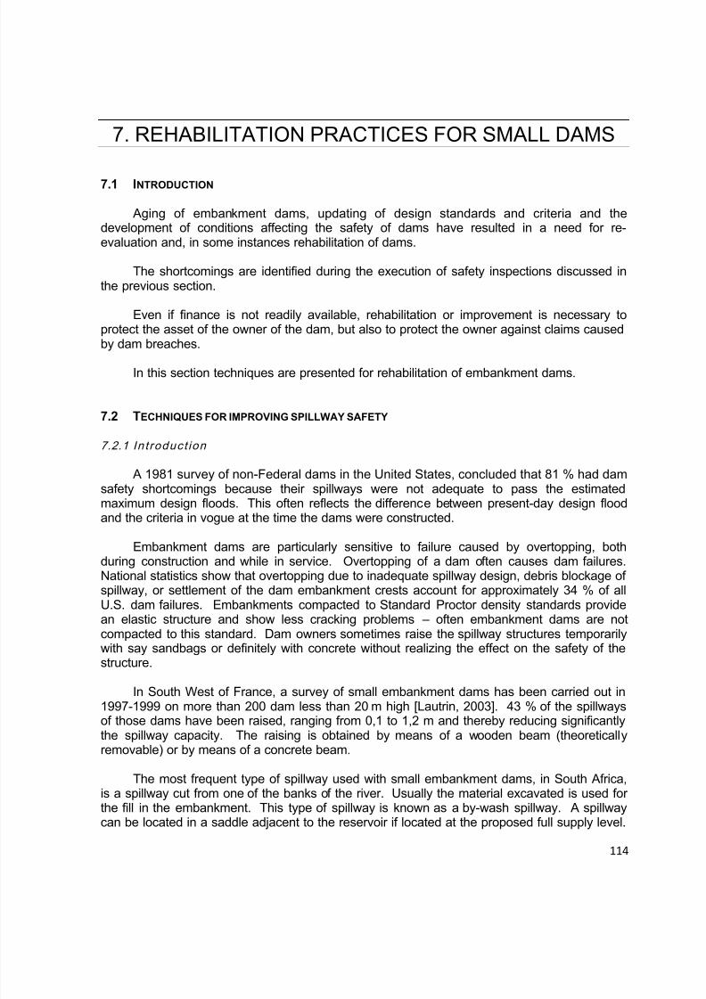
8/12/2019 ICOLD Small Dams Sept 2011
http://slidepdf.com/reader/full/icold-small-dams-sept-2011 114/149
114
7. REHABILITATION PRACTICES FOR SMALL DAMS
7.1 INTRODUCTION
Aging of embankment dams, updating of design standards and criteria and thedevelopment of conditions affecting the safety of dams have resulted in a need for re-evaluation and, in some instances rehabilitation of dams.
The shortcomings are identified during the execution of safety inspections discussed inthe previous section.
Even if finance is not readily available, rehabilitation or improvement is necessary toprotect the asset of the owner of the dam, but also to protect the owner against claims caused
by dam breaches.In this section techniques are presented for rehabilitation of embankment dams.
7.2 TECHNIQUES FOR IMPROVING SPILLWAY SAFETY
7.2.1 Int roduct ion
A 1981 survey of non-Federal dams in the United States, concluded that 81 % had damsafety shortcomings because their spillways were not adequate to pass the estimatedmaximum design floods. This often reflects the difference between present-day design floodand the criteria in vogue at the time the dams were constructed.
Embankment dams are particularly sensitive to failure caused by overtopping, bothduring construction and while in service. Overtopping of a dam often causes dam failures.National statistics show that overtopping due to inadequate spillway design, debris blockage ofspillway, or settlement of the dam embankment crests account for approximately 34 % of allU.S. dam failures. Embankments compacted to Standard Proctor density standards providean elastic structure and show less cracking problems – often embankment dams are notcompacted to this standard. Dam owners sometimes raise the spillway structures temporarilywith say sandbags or definitely with concrete without realizing the effect on the safety of thestructure.
In South West of France, a survey of small embankment dams has been carried out in1997-1999 on more than 200 dam less than 20 m high [Lautrin, 2003]. 43 % of the spillwaysof those dams have been raised, ranging from 0,1 to 1,2 m and thereby reducing significantlythe spillway capacity. The raising is obtained by means of a wooden beam (theoreticallyremovable) or by means of a concrete beam.
The most frequent type of spillway used with small embankment dams, in South Africa,is a spillway cut from one of the banks of the river. Usually the material excavated is used forthe fill in the embankment. This type of spillway is known as a by-wash spillway. A spillwaycan be located in a saddle adjacent to the reservoir if located at the proposed full supply level.

8/12/2019 ICOLD Small Dams Sept 2011
http://slidepdf.com/reader/full/icold-small-dams-sept-2011 115/149
115
These spillways can be lined or unlined. Normally the following problems are identified forexisting by-wash spillways.
7.2.2 Spil lway Capacit y
Inadequate flood handling capacity not meeting design standards is normally caused byunderestimating the design flood, not acknowledging the effect of the upstream approachchannel on the hydraulic gradient or not ensuring that the dam was constructed with its total freeboard over the entire crest length of the dam. The hydraulic control must be correctlydefined for the design flow by determining the hydraulic flow and energy lines based on thecorrect sectional information. Furthermore, the design floods associated with the classificationshown in section 5.2 can be used as a guide.
7.2.3 Backward Erosion Contro l
Backward erosion of a spillway channel occurs due to fast flowing water over soil andweathered rockfill materials. An example is shown in Figure 7.1.
Fig. 7.1 – Backward erosion of the by-wash Spillway of Toleni Dam in South Africa
This may lead to undermining of the hydraulic control structure e.g. a concrete sill or aweir if that structure is also founded on erodible material. Backward erosion can be preventedby providing a control structure e.g. concrete weir founded on a solid unerodible foundation.Erosion can be controlled by limiting the depth and the velocity of the water depending on thetype of gravel or soil medium between grasses in the case of grass lined channels. In aridareas care must be taken not to use grass as the grass will die and provide no resistance to
erosion i.e. it will not be eff ective. A “better practice” is to protect the soil with a liner or rockfillas described in the following sections. The erodibility of spillways in unweathered tomoderately weathered rock can be evaluated in accordance with water power and the rockstrength using the chart shown in Figure 7.1 (Van Schalkwyk, 1994). The following formulaapplies:
P = ρw * Q1:100/b * sWhere
P = Power per unit area (kW/m2)

8/12/2019 ICOLD Small Dams Sept 2011
http://slidepdf.com/reader/full/icold-small-dams-sept-2011 116/149
116
ρw = Density of water in kg/m3 Q = Discharge in m3/sb = Width of channel in ms = Slope of channel (m/m)
7.2.4 Spil lway Chute or Spi l lway Return Chann el Al ignment
Change of direction in the spillway chute or spillway return channel during supercriticalflow conditions provides problems regarding erosion of materials. Water in supercritical flowdoes not change direction and tends to carry on straight except if the floor is elevatedcorrectly. Straight chutes for supercritical flow conditions must be provided.
7.2.5 Deformation of Spi l lway Structu res Provided Over Emb ankm ents
It is possible to construct the spillway over the embankment, with two conditions:
Expected settlement of the foundation must be very low or must occur mostly duringconstruction of the original embankment (short-term settlement).
Expected settlement of the original embankment must be very low, that means goodcompaction of the material.
A concrete spillway constructed over an earthfill embankment on soft foundations willtherefore settle with movement of the concrete panels. Failure may be caused due to ingressof overflowing water and uplift of concrete panels. Although often expensive, (or costly)minimum risks and best solutions for the improvement of spillways include the “tried and
tested” approach of location of spillways on solid foundations.
Nevertheless, construction of an additional spillway over the embankment of an existingdam may be a solution to consider, as settlement has often ceased after some decades.
7.2.6 Erosio n of the Abutment Wall Between the Emb ankm ent and the Spi l lway
The solution recommended for the transition between the embankment and the spillwayis a concrete wall i.e. mass gravity or cantilever (depending on foundation, height andeconomics).
If the protection of an earthfill abutment (or the training wall of one side of a spillwayreturn channel) comprises a layer (or layers) of rock (or rip-rap), it may be damaged (orwashed away) after cracking of soil and erosion by storm water or high powered flowing water.Materials used for this type of erosion protection must be carefully designed to accommodatethe unit power of the flowing water. The protection must also be designed to accommodatethe safety evaluation check discharge.
7.2.7 Gabion s Used as Sil l in by-pass Chan nels
Gabion baskets must be considered with care as they have shortcomings:
Very often the galvanized steel wire that makes up the rectangular (or square) panelsof the baskets corrodes and results in individual stones in the baskets being exposed to

8/12/2019 ICOLD Small Dams Sept 2011
http://slidepdf.com/reader/full/icold-small-dams-sept-2011 117/149
117
flowing water. Flowing water with high power (kW/m2) can remove stones if too small. Wherethere has been poor maintenance, total breakdown of a Gabion will take place if most of apanel has corroded and “broken down” before repair (or rehabilitation to its original functionalcondition)
Stones and the “upper panels” of Gabions may be removed by vandalism.
A cut-off structure connected to rock should be considered.
7.3 TECHNIQUES FOR IMPROVING EMBANKMENT SAFETY
7.3.1 Techniqu es to Overcome Flood Handl ing Prob lem
7.3.1.1 Parapet Wall
A parapet wall can be used to raise the crest of a consolidated embankment crest. The
concrete parapet must be designed to accommodate water loads including uplift but the safetyfactors against overtopping and shear failure if exposed to the PHC 3 floods can be selectedclose to 1 in this case. An impermeable membrane must be designed between the imperviouscore of the embankment and the base (or underside) of the parapet wall. The footing normallyhave to be imbedded into the embankment crest.
7.3.1.2 Raise Emb ankm ent Crest
Generally (but not always) the lowest cost option to overcome inadequate flood handlingproblem is to increase the total freeboard of the dam by raising the crest of the embankment.This is normally achieved by adding earthfill to the downstream face of the embankmentstarting from the toe of the embankment (see Figure 7.2). In addition to the fact that the
spillway must be designed to accommodate higher “recommended design and safetyevaluation check floods”, respectively, the three (3) topics that are listed below must beaddressed in the context of the structural integrity of the embankment:
The stability of the downstream slope (and “in-situ” foundation) must be analyzedtaking into account that the existing embankment (or portions thereof) are structural zones(or components) of the raised embankment. The engineering properties of the earthfillmaterials of the existing embankment and the “new” earthfill section should be determined withreasonable confidence (i.e. a representative (or appropriate) sampling and laboratory testingprogram) and used in any analyses.
A “sand chimney drain” must be considered at the interface between the downstream
face of the existing embankment and the “new” earthfill section (or zone). This will draw downthe phreatic surface and intercept any possible seepage through the embankment.
A new toe drain possibly connected to the existing toe drain must be considered.
An example is shown in Figure 7.2.
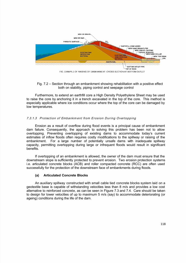
8/12/2019 ICOLD Small Dams Sept 2011
http://slidepdf.com/reader/full/icold-small-dams-sept-2011 118/149
118
Fig. 7.2 – Section through an embankment showing rehabilitation with a positive effectboth on stability, piping control and seepage control
Furthermore, to extend an earthfill core a High Density Polyethylene Sheet may be usedto raise the core by anchoring it in a trench excavated in the top of the core. This method isespecially applicable where ice conditions occur where the top of the core can be damaged bylow temperatures.
7.3.1.3 Protect ion of Embankm ent from Erosion Dur ing Overtopping
Erosion as a result of overflow during flood events is a principal cause of embankmentdam failure. Consequently, the approach to solving this problem has been not to allowovertopping. Preventing overtopping of existing dams to accommodate today’s current
estimates of inflow floods often requires costly modifications to the spillway or raising of theembankment. For a large number of potentially unsafe dams with inadequate spillwaycapacity, permitting overtopping during large or infrequent floods would result in significantbenefits.
If overtopping of an embankment is allowed, the owner of the dam must ensure that thedownstream slope is sufficiently protected to prevent erosion. Two erosion protection systemsi.e. articulated concrete blocks (ACB) and roller compacted concrete (RCC) are often usedsuccessfully for the protection of the downstream face of embankments during floods.
(a) Articulated Concrete Blocks
An auxiliary spillway constructed with small cable tied concrete blocks system laid on ageotextile base is capable of withstanding velocities less than 8 m/s and provides a low costalternative to reinforced concrete, as can be seen in Figure 7.3 and 7.4. Care should be takento design for lower velocities of up to maximum 5 m/s (say) to accommodate deteriorating (orageing) conditions during the life of the dam.
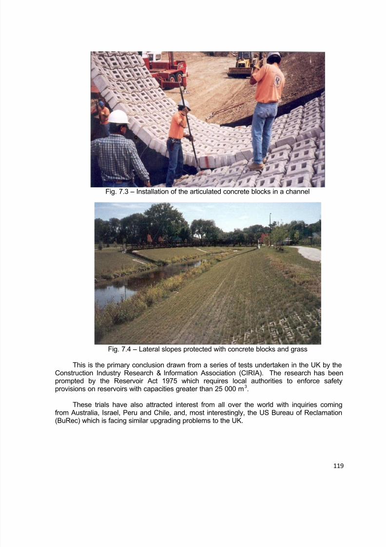
8/12/2019 ICOLD Small Dams Sept 2011
http://slidepdf.com/reader/full/icold-small-dams-sept-2011 119/149
119
Fig. 7.3 – Installation of the articulated concrete blocks in a channel
Fig. 7.4 – Lateral slopes protected with concrete blocks and grass
This is the primary conclusion drawn from a series of tests undertaken in the UK by theConstruction Industry Research & Information Association (CIRIA). The research has been
prompted by the Reservoir Act 1975 which requires local authorities to enforce safetyprovisions on reservoirs with capacities greater than 25 000 m3.
These trials have also attracted interest from all over the world with inquiries comingfrom Australia, Israel, Peru and Chile, and, most interestingly, the US Bureau of Reclamation(BuRec) which is facing similar upgrading problems to the UK.
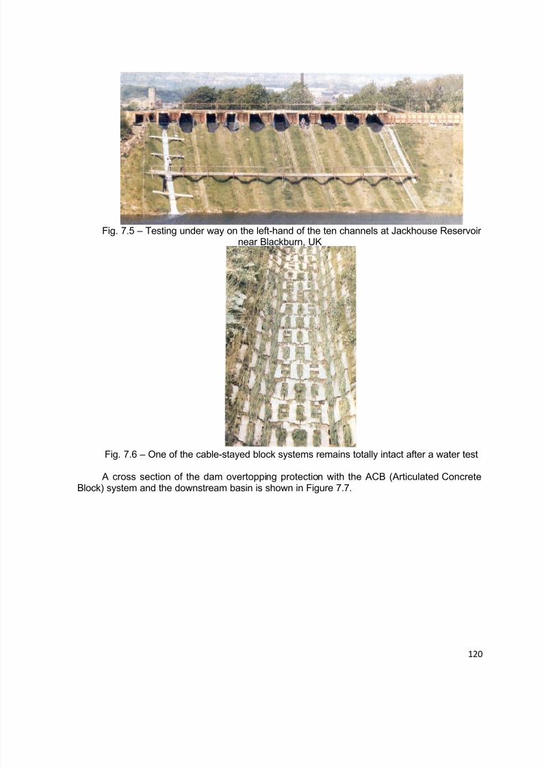
8/12/2019 ICOLD Small Dams Sept 2011
http://slidepdf.com/reader/full/icold-small-dams-sept-2011 120/149
120
Fig. 7.5 – Testing under way on the left-hand of the ten channels at Jackhouse Reservoirnear Blackburn, UK
Fig. 7.6 – One of the cable-stayed block systems remains totally intact after a water test
A cross section of the dam overtopping protection with the ACB (Articulated ConcreteBlock) system and the downstream basin is shown in Figure 7.7.
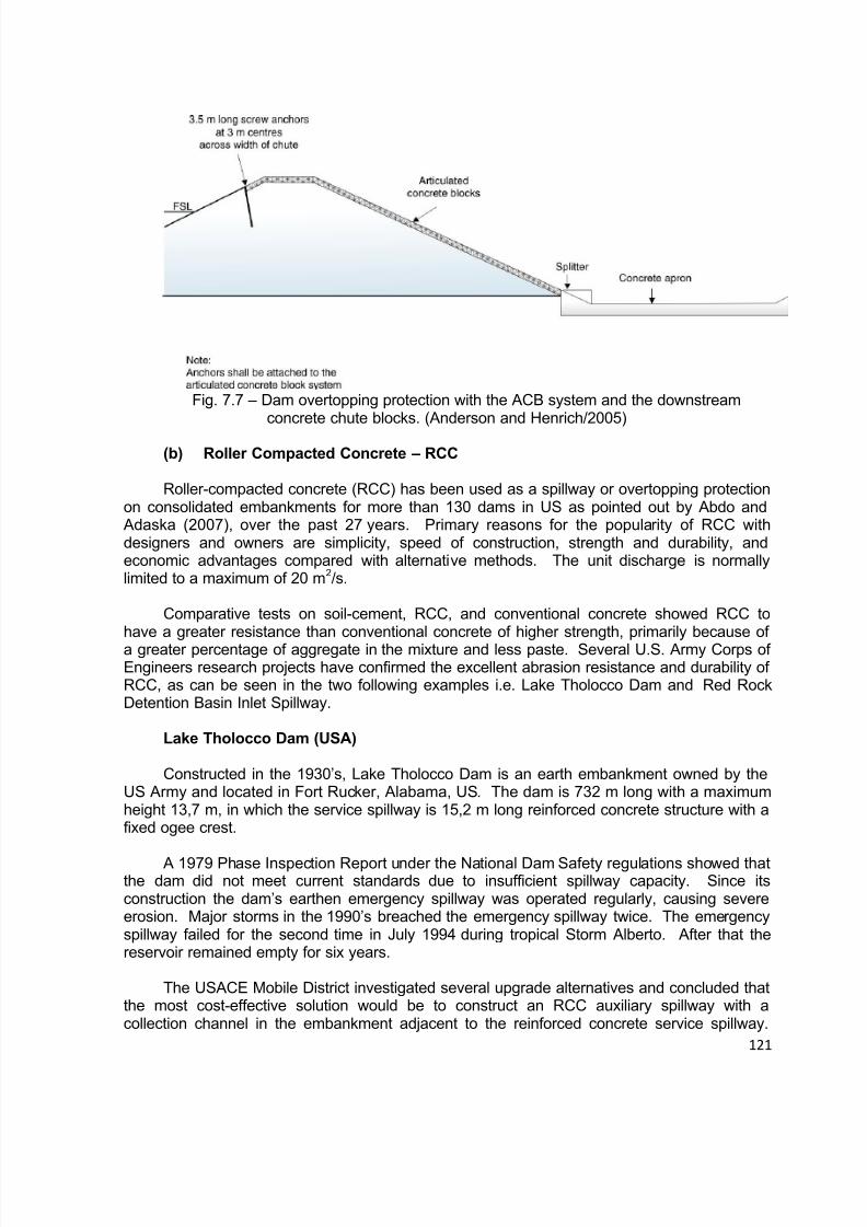
8/12/2019 ICOLD Small Dams Sept 2011
http://slidepdf.com/reader/full/icold-small-dams-sept-2011 121/149
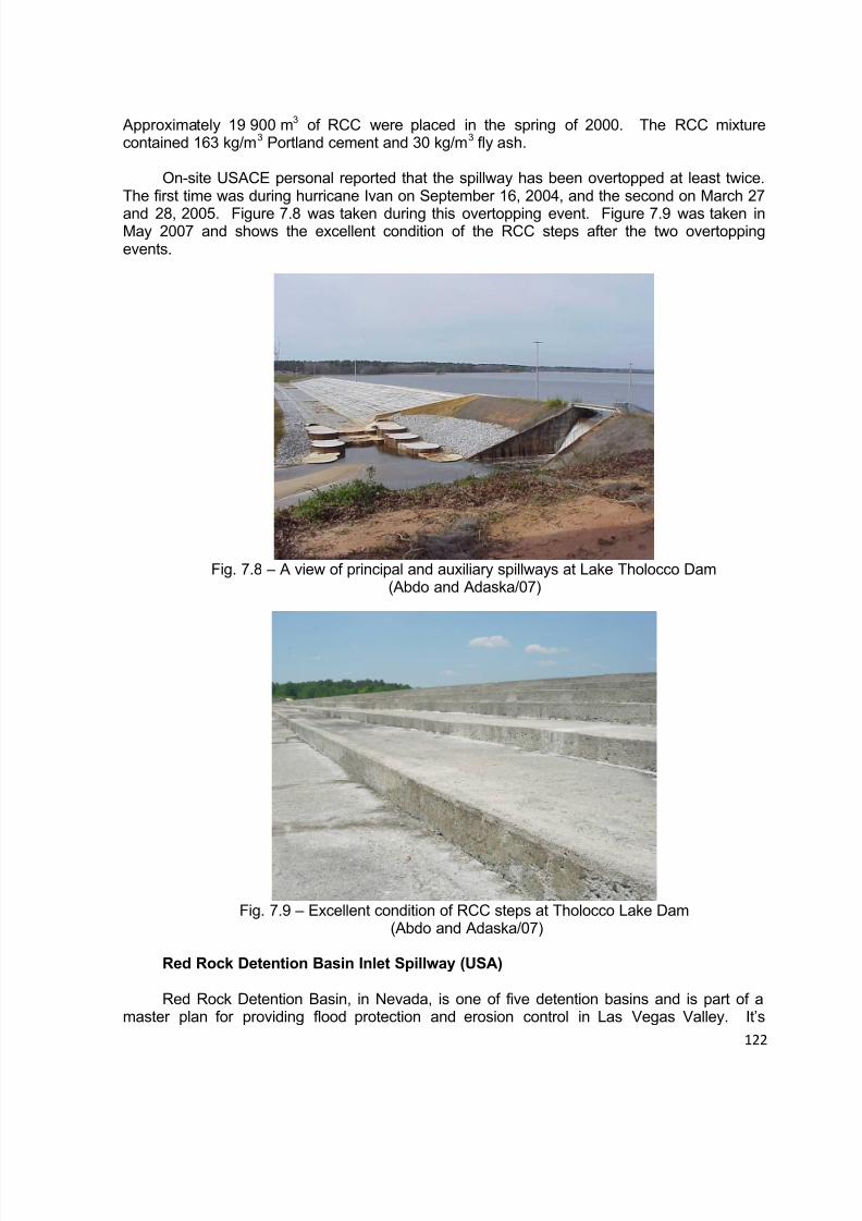
8/12/2019 ICOLD Small Dams Sept 2011
http://slidepdf.com/reader/full/icold-small-dams-sept-2011 122/149
122
Approximately 19 900 m3 of RCC were placed in the spring of 2000. The RCC mixturecontained 163 kg/m3 Portland cement and 30 kg/m3 fly ash.
On-site USACE personal reported that the spillway has been overtopped at least twice.The first time was during hurricane Ivan on September 16, 2004, and the second on March 27
and 28, 2005. Figure 7.8 was taken during this overtopping event. Figure 7.9 was taken inMay 2007 and shows the excellent condition of the RCC steps after the two overtoppingevents.
Fig. 7.8 – A view of principal and auxiliary spillways at Lake Tholocco Dam(Abdo and Adaska/07)
Fig. 7.9 – Excellent condition of RCC steps at Tholocco Lake Dam(Abdo and Adaska/07)
Red Rock Detention Basin Inlet Spillway (USA)
Red Rock Detention Basin, in Nevada, is one of five detention basins and is part of amaster plan for providing flood protection and erosion control in Las Vegas Valley. It’s
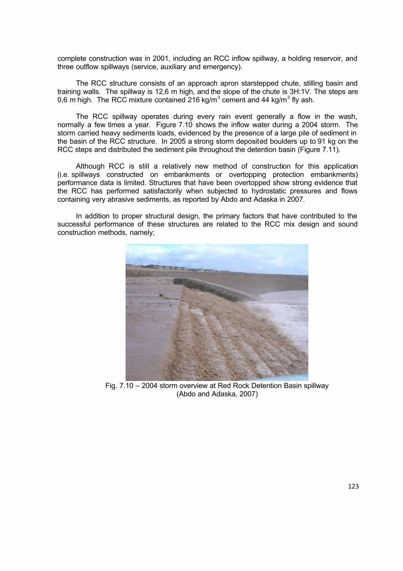
8/12/2019 ICOLD Small Dams Sept 2011
http://slidepdf.com/reader/full/icold-small-dams-sept-2011 123/149
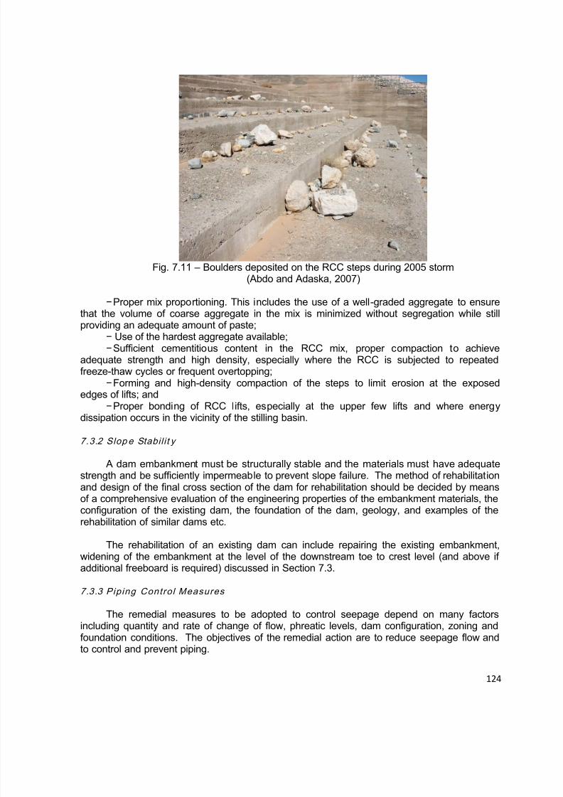
8/12/2019 ICOLD Small Dams Sept 2011
http://slidepdf.com/reader/full/icold-small-dams-sept-2011 124/149

8/12/2019 ICOLD Small Dams Sept 2011
http://slidepdf.com/reader/full/icold-small-dams-sept-2011 125/149

8/12/2019 ICOLD Small Dams Sept 2011
http://slidepdf.com/reader/full/icold-small-dams-sept-2011 126/149
126
7.3.4.1 Seepage Barr iers and Cutoff Systems
This section provides a brief overview of commonly used seepage control systems.
Seepage cutoffs and barriers are intended to reduce the amount of seepage and
minimize downstream pressures and exit gradients. Depending on the site and foundationconditions, seepage cutoff systems may provide either:
Positive cutoff that completely penetrates pervious zones and ties into impervious soillayers or bedrock in the dam foundation and abutments, or
− Partial cutoff, which is sometimes used for deep pervious foundations to lengthen theseepage path and reduce exit gradients to acceptable levels.
There are many different types of cutoff systems that are used for dam rehabilitation.The primary objective is to provide a low permeability element within the dam and/or itsfoundation, either as the primary seepage barrier or to supplement existing barriers. Cutoffs
may be classified according to their stiffness, the type of materials used, or constructionmethods used.
The terms cutoff “wall” or “diaphragm” are often used to distinguish seepage barriers thatare thin compared to the surrounding embankment. Barriers employed for dam rehabilitationmay be constructed through the dam and foundation from the existing dam crest (diaphragmor wall).
Alternatively barriers may be constructed using a liner system on the upstream face ofthe dam in combination with vertical or horizontal seepage barriers extending from theupstream toe.
Some of the seepage barriers that are commonly used for dam rehabilitation are listed inTable 7.1 .Most of those solutions require lowering of the reservoir level significantly, in orderto reduce hydraulic gradients during rehabilitation and the risk of wash-out of cement andbentonite. In case of construction of rehabilitation works on the upstream face of the dam, thereservoir must be emptied.
Table 7.1 – Common Seepage cut-off measures identified for Alluvium and EarthfillFoundations of small dams
Type of cutoff Method Materials usedRemarks and
References
Core trench:
Open trench isexcavated and, ifstable, filling with one ofthe materials is done
EarthfillSoil-bentoniteConcrete-bentonite
Depth limited to some
metres
Slurry trench: Slurrywall, concrete wall,
tremmy
Open trench byextended backhoe, keptopen and stabilizedwith bentonite slurry
Concrete by tremmypipe. Primary andsecondary panels areinserted once sufficientstrength has beenidentified
Figure 7.4 andFigure 7.9 and 7.10
Sheet piles curtain Inserted by vibratory Steel Curtain not taken to
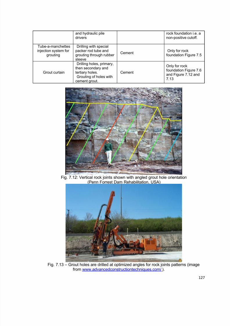
8/12/2019 ICOLD Small Dams Sept 2011
http://slidepdf.com/reader/full/icold-small-dams-sept-2011 127/149
127
and hydraulic piledrivers
rock foundation i.e. anon-positive cutoff.
Tube-a-manchettesinjection system for
grouting
Drilling with specialpacker rod tube andgrouting through rubbersleeve
CementOnly for rock
foundation Figure 7.5
Grout curtain
Drilling holes, primary,then secondary andtertiary holes.Grouting of holes with
cement grout.
Cement
Only for rockfoundation Figure 7.6and Figure 7.12 and7.13
Fig. 7.12: Vertical rock joints shown with angled grout hole orientation(Penn Forrest Dam Rehabilitation, USA)
Fig. 7.13 – Grout holes are drilled at optimized angles for rock joints patterns (imagefrom www.advancedconstructiontechniques.com/ ).

8/12/2019 ICOLD Small Dams Sept 2011
http://slidepdf.com/reader/full/icold-small-dams-sept-2011 128/149
128
7.3.4.2 Seepage Intercept io n and Exit Contro l With Fi l ters and Drains
Filters are typically the first line of defense against piping and internal erosion. Filtersand drains are often incorporated as remedial systems to control seepage in existing
embankment dams.
For small embankment dams that can be dewatered, it is possible to install centralvertical filters in open trenches. In the southwestern US, for example, hundreds of smallhomogeneous earth dams were constructed for flood control under a federal governmentwatershed protection program that was initiated in 1954. Many of these flood controlstructures were subsequently found to have developed severe cracking caused by desiccationshrinkage, differential settlement, and collapse on inundation of metastable soils in the damfoundations. However, recognizing the potential risks associated with piping and internalerosion failure modes in cracked homogeneous embankment dams, NRCS retrofitted a largenumber of the cracked dams with central sand and gravel filters, as shown on Figure 7.14.NRCS also performed landmark research studies that advanced the general understanding of
the performance and design requirements for granular filters (Sherard et al., 1984a, 1984b;Sherard and Dunnigan, 1985, 1989).
For water retention dams, or dams that are too high for open trenching from the crest,the filter and drain zones can be constructed as weighted berms and wedges of fill on thedownstream side of the dam.
Fig. 7.14 – Central sand filter installed by open trenching from the crest of an existinglow-height flood control dam in southwestern USA
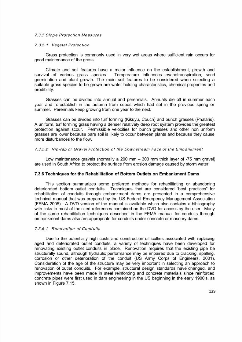
8/12/2019 ICOLD Small Dams Sept 2011
http://slidepdf.com/reader/full/icold-small-dams-sept-2011 129/149
129
7.3.5 Slop e Protect ion Measu res
7.3.5.1 Vegetal Protec tio n
Grass protection is commonly used in very wet areas where sufficient rain occurs for
good maintenance of the grass.
Climate and soil features have a major influence on the establishment, growth andsurvival of various grass species. Temperature influences evapotranspiration, seedgermination and plant growth. The main soil features to be considered when selecting asuitable grass species to be grown are water holding characteristics, chemical properties anderodibility.
Grasses can be divided into annual and perennials. Annuals die off in summer eachyear and re-establish in the autumn from seeds which had set in the previous spring orsummer. Perennials keep growing from one year to the next.
Grasses can be divided into turf forming (Kikuyu, Couch) and bunch grasses (Phalaris). A uniform, turf forming grass having a denser relatively deep root system provides the greatestprotection against scour. Permissible velocities for bunch grasses and other non uniformgrasses are lower because bare soil is likely to occur between plants and because they causemore disturbances to the flow.
7.3.5.2 Rip-rap or Gravel Protect ion of the Dow nstream Face of the Emb ankment
Low maintenance gravels (normally a 200 mm – 300 mm thick layer of -75 mm gravel)are used in South Africa to protect the surface from erosion damage caused by storm water.
7.3.6 Techniques for the Rehabilitation of Bottom Outlets on Embankment Dams
This section summarizes some preferred methods for rehabilitating or abandoningdeteriorated bottom outlet conduits. Techniques that are considered “best practices” forrehabilitation of conduits through embankment dams are presented in a comprehensivetechnical manual that was prepared by the US Federal Emergency Management Association(FEMA 2005). A DVD version of the manual is available which also contains a bibliographywith links to most of the cited references contained on the DVD for access by the user. Manyof the same rehabilitation techniques described in the FEMA manual for conduits throughembankment dams also are appropriate for conduits under concrete or masonry dams.
7.3.6.1 Renovation of Cond uits
Due to the potentially high costs and construction difficulties associated with replacingaged and deteriorated outlet conduits, a variety of techniques have been developed forrenovating existing outlet conduits in place. Renovation requires that the existing pipe bestructurally sound, although hydraulic performance may be impaired due to cracking, spalling,corrosion or other deterioration of the conduit (US Army Corps of Engineers, 2001).Consideration of the age of the structure may be very important in selecting an approach torenovation of outlet conduits. For example, structural design standards have changed, andimprovements have been made in steel reinforcing and concrete materials since reinforcedconcrete pipes were first used in dam engineering in the US beginning in the early 1900’s, asshown in Figure 7.15.
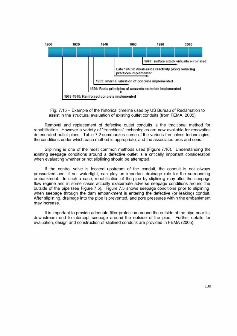
8/12/2019 ICOLD Small Dams Sept 2011
http://slidepdf.com/reader/full/icold-small-dams-sept-2011 130/149

8/12/2019 ICOLD Small Dams Sept 2011
http://slidepdf.com/reader/full/icold-small-dams-sept-2011 131/149
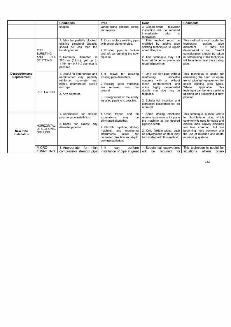
8/12/2019 ICOLD Small Dams Sept 2011
http://slidepdf.com/reader/full/icold-small-dams-sept-2011 132/149

8/12/2019 ICOLD Small Dams Sept 2011
http://slidepdf.com/reader/full/icold-small-dams-sept-2011 133/149
133
Conditions Pros Cons Comments
types only, such as clay,reinforced fiberglass, andconcrete pipes.
2. Useful for any diameter,152 mm (6 in.) or greater.
depths and tunnel throughvarious soils and rocksizes.
2. Gradient and alignmentof newly installed pipe isprecisely controlled.
insertion and extraction ofthe micro-tunnelingmachine.
2. Unexpected groundconditions can lead to ablocked machine, requiringan expensive removal.
trench installation of pipe isnot economical or possible.
Also, it is very useful forinstallation of gravitypipelines that require strictcontrol of gradient anddirection.

8/12/2019 ICOLD Small Dams Sept 2011
http://slidepdf.com/reader/full/icold-small-dams-sept-2011 134/149
134
Fig. 7.16 – Example of sliplining – insertion of plastic (high density polyethylene) pipe intolarger diameter concrete pipe (from FEMA, 2005)
Need filter at downstream
when sliplining
Seepage before slipliner
Seepage after slipliner
(without filter)(with filter)
Filter diaphragm
Fig. 7.17 – Possible effect of a slip-liner on pore pressure in an embankment dam, illustratingthe need for a downstream filter diaphragm (courtesy of Maryland (USA) Dam Safety Division)
7.3.6.2 Filter Ar ound Cond uits
Filters are generally accepted as the preferred method to protect against seepage orleakage around the outside of conduits that penetrate the dam or its foundation. Use of anti-seep (cutoff) collars on conduits is no longer considered acceptable practice due to the highincidence of historic failures attributed to poor compaction control around these protrusions onthe conduits. Filters used in conjunction with conduits generally fall under three categories:chimney filters, filter diaphragms, and filter collars. Detailed design recommendations for filtersaround conduits are provided in FEMA (2005), and some key points are summarized in this
section.

8/12/2019 ICOLD Small Dams Sept 2011
http://slidepdf.com/reader/full/icold-small-dams-sept-2011 135/149
135
Embankment dams that have properly designed and constructed chimney filters normallydo not require a separate filter zone to control seepage around the outlet conduit. When fullhydraulic height filters are installed as a seepage remedy for the embankment (see Figure 7.16and Figure 7.17, for example), care should be taken to incorporate the filter zone around theoutlet conduit as well.
A filter diaphragm is a zone of engineered filter sand placed around the conduit tospecified dimensions. The dimensions shown in Figure 7.18 are based on guidance providedby NRCS (1989, 1990). Normally a minimum width of 1 m around the conduit is provided.Other details for positioning and designing filter diaphragms are provided in FEMA (2005).Filter diaphragms are economical and effective seepage rehabilitation features that can beincorporated on dam embankments that do not have chimney filters, or which may havedefective filter zones.
Fig. 7.18 – Typical configuration of a filter diaphragm for conduits through embankment dams(after FEMA, 2005; NRCS 1989, 1990)
A filter collar is a zone of filter material (typically sand) that completely surrounds aspecified length of the outlet conduit. The lateral dimensions beyond the outside of the conduitare limited in extent compared to a filter diaphragm. It is recommended that filter collars beused only for special conditions when the only seepage considered likely is flow around theperiphery of the pipe, and soil conditions are less conducive to erosion.
Sometimes it is difficult to construct the collar in the “downstream zone” of anembankment when the reservoir is full, or partially full. In such cases the conduit pipe can belengthened and covered with a berm of soil on the downstream side of the dam. Specialattention must be paid to the control valve at the downstream end of the existing outlet pipe if itis to be left in place “as a spacer” so that sufficient space is added for the connection by bolts.
7.3.6.3 Pipe Ab ando nment
Outlet pipe must sometimes be abandoned, such as where the conduit has deterioratedto the point that it is no longer safe to operate. It is often considered technically andeconomically more feasible to abandon the conduit in place, rather than excavate and remove
it. If it is necessary for an “abandoned conduit” to remain in place in the dam or its foundation,the conduit must filled with grout. A filter diaphragm should be installed around the grouted

8/12/2019 ICOLD Small Dams Sept 2011
http://slidepdf.com/reader/full/icold-small-dams-sept-2011 136/149
136
conduit to protect against possible seepage (or flow) around the periphery of the grouted (orsealed) pipe/conduit. Some considerations relating to the abandonment of conduits include(FEMA, 2005):
Complete or partial filling of the conduit with grout: Normally, complete backfilling ofthe pipe with grout is recommended. However, it may be difficult to completely fill the pipe fullof grout if the pipe is long and access is limited to one end of the pipe. It may be possible toaccess the pipe by drilling through the dam from the crest to intersect the conduit.
There are inherent risks associated with hydraulic fracturing both from drilling into thedam and injection of grout from the crest of the dam. These potential risks must be weighedagainst the desire to completely fill the pipe with grout. If drilling into the dam is necessary to fillthe pipe, the preferred method is dry augering to avoid risk of hydraulic fracturing due to drillingfluids.
If water is flowing into the conduit and cannot be stopped by lowering the reservoir, itmay be necessary to seal the pipe with a temporary bulkhead or inflatable bladder.
7.3.7 Techniq ues for Rehabi l i tat ion o f Hydrom echanical Compo nents
All valves and hydromechanical equipment used for releasing water from a dam must beproperly maintained. It is important to remember that under certain circumstances an unsafecondition could develop at a dam and there may be a requirement to empty the reservoir (ordraw down the reservoir to a “ safe level ” ) as quickly as possible. It is important to service andexercise the valve and other mechanical components regularly to ensure that they areoperational at all times. For example, it is recommended that for a dam with basic outlet works,that the control valve be operated at least four times per year to make sure it is functioningproperly.
If a valve is difficult to operate, for example a tight handwheel, or one which requiresexcessive force to turn it for its full range, this is a clear indication of a developing problem that
requires attention. It is possible to exercise a valve without losing water stored in the reservoirwhen the spillway is flowing because water is being passed downstream anyway. This “mode ofoperation” is recommended at the tail end of flow over a spillway because opening a valve atthe beginning of spillway discharge may worsen the natural increase in discharge downstreamof the dam.
Fig. 7.19 – What are the chances that this valve will work in an emergency? (SMEC/2006)
Provision should be made at the discharge end of an outlet pipe to reduce the velocity ofthe water and to dissipate energy. Heavy (and suitably dimensioned) rock placed on a layer ofcrushed rock will minimize erosion. Construction of an effective concrete outlet structure e.g.
“Impact-Type Stilling Basin” (Design of Small Dams, 1987) will dissipate the energy of the water
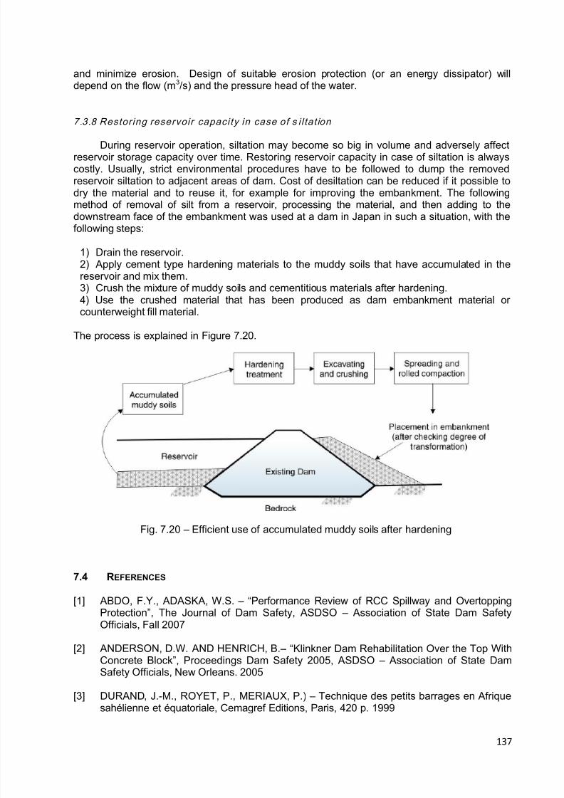
8/12/2019 ICOLD Small Dams Sept 2011
http://slidepdf.com/reader/full/icold-small-dams-sept-2011 137/149
137
and minimize erosion. Design of suitable erosion protection (or an energy dissipator) willdepend on the flow (m3/s) and the pressure head of the water.
7.3.8 Restoring reservoir capacity in case of s i l tat ion
During reservoir operation, siltation may become so big in volume and adversely affectreservoir storage capacity over time. Restoring reservoir capacity in case of siltation is alwayscostly. Usually, strict environmental procedures have to be followed to dump the removedreservoir siltation to adjacent areas of dam. Cost of desiltation can be reduced if it possible todry the material and to reuse it, for example for improving the embankment. The followingmethod of removal of silt from a reservoir, processing the material, and then adding to thedownstream face of the embankment was used at a dam in Japan in such a situation, with thefollowing steps:
1) Drain the reservoir.2) Apply cement type hardening materials to the muddy soils that have accumulated in the
reservoir and mix them.3) Crush the mixture of muddy soils and cementitious materials after hardening.4) Use the crushed material that has been produced as dam embankment material orcounterweight fill material.
The process is explained in Figure 7.20.
Fig. 7.20 – Efficient use of accumulated muddy soils after hardening
7.4 REFERENCES
[1] ABDO, F.Y., ADASKA, W.S. – “Performance Review of RCC Spillway and OvertoppingProtection”, The Journal of Dam Safety, ASDSO – Association of State Dam SafetyOfficials, Fall 2007
[2] ANDERSON, D.W. AND HENRICH, B. – “Klinkner Dam Rehabilitation Over the Top WithConcrete Block”, Proceedings Dam Safety 2005, ASDSO – Association of State DamSafety Officials, New Orleans. 2005
[3] DURAND, J.-M., ROYET, P., MERIAUX, P.) – Technique des petits barrages en Afriquesahélienne et équatoriale, Cemagref Editions, Paris, 420 p. 1999
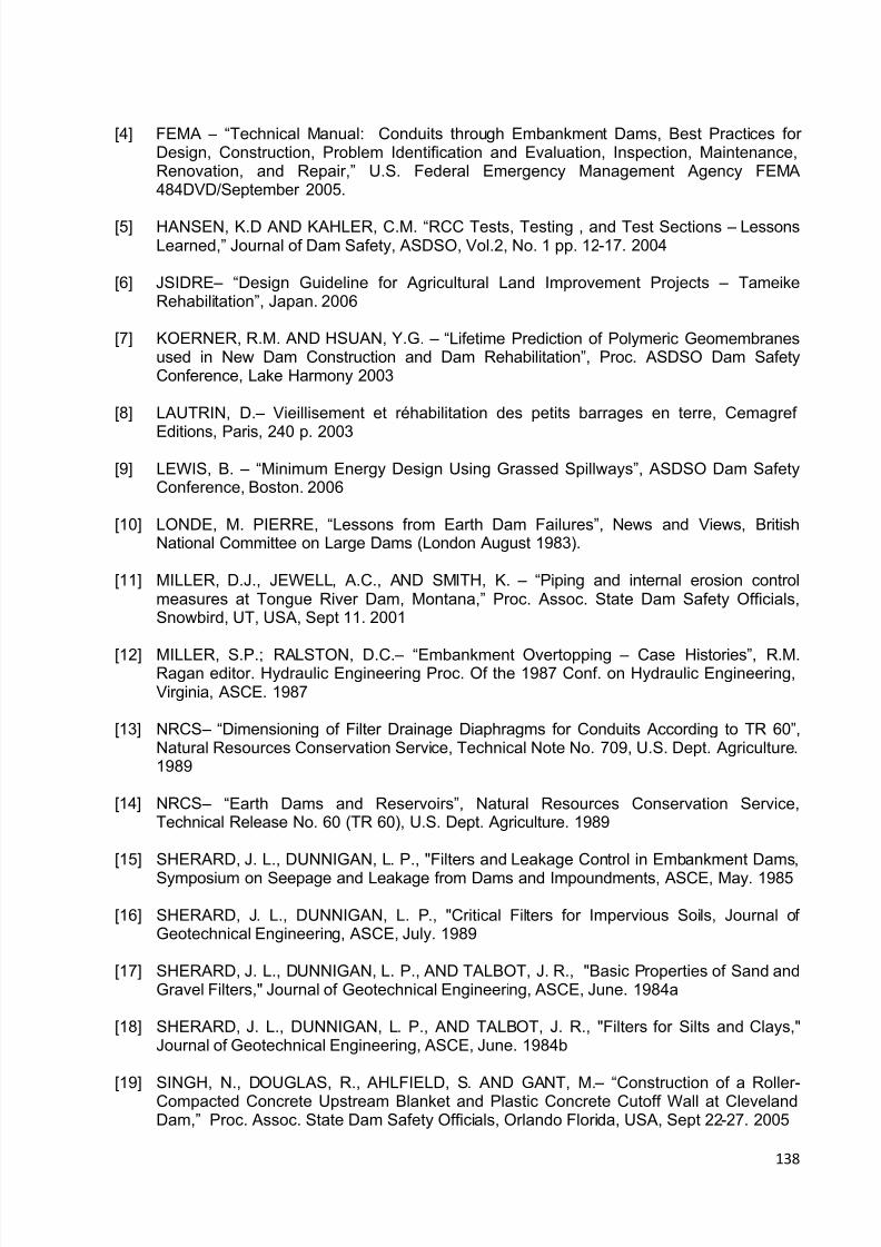
8/12/2019 ICOLD Small Dams Sept 2011
http://slidepdf.com/reader/full/icold-small-dams-sept-2011 138/149
138
[4] FEMA – “Technical Manual: Conduits through Embankment Dams, Best Practices forDesign, Construction, Problem Identification and Evaluation, Inspection, Maintenance,Renovation, and Repair,” U.S. Federal Emergency Management Agency FEM A484DVD/September 2005.
[5] HANSEN, K.D AND KAHLER, C.M. “RCC Tests, Testing , and Test Sections – LessonsLearned,” Journal of Dam Safety, ASDSO, Vol.2, No. 1 pp. 12-17. 2004
[6] JSIDRE – “Design Guideline for Agricultural Land Improvement Projects – TameikeRehabilitation”, Japan. 2006
[7] KOERNER, R.M. AND HSUAN, Y.G. – “Lifetime Prediction of Polymeric Geomembranesused in New Dam Construction and Dam Rehabilitation”, Proc. ASDSO Dam SafetyConference, Lake Harmony 2003
[8] LAUTRIN, D. – Vieillisement et réhabilitation des petits barrages en terre, Cemagref
Editions, Paris, 240 p. 2003
[9] LEWIS, B. – “Minimum Energy Design Using Grassed Spillways”, ASDSO Dam SafetyConference, Boston. 2006
[10] LONDE, M. PIERRE, “Lessons from Earth Dam Failures”, News and Views, BritishNational Committee on Large Dams (London August 1983).
[11] MILLER, D.J., JEWELL, A.C., AND SMITH, K. – “Piping and internal erosion controlmeasures at Tongue River Dam, Montana,” Proc. Assoc. State Dam Safety Officials,Snowbird, UT, USA, Sept 11. 2001
[12] MILLER, S.P.; RALSTON, D.C. – “Embankment Overtopping – Case Histories”, R.M.Ragan editor. Hydraulic Engineering Proc. Of the 1987 Conf. on Hydraulic Engineering,Virginia, ASCE. 1987
[13] NRCS – “Dimensioning of Filter Drainage Diaphragms for Conduits According to TR 60”,Natural Resources Conservation Service, Technical Note No. 709, U.S. Dept. Agriculture.1989
[14] NRCS – “Earth Dams and Reservoirs”, Natural Resources Conservation Service,Technical Release No. 60 (TR 60), U.S. Dept. Agriculture. 1989
[15] SHERARD, J. L., DUNNIGAN, L. P., "Filters and Leakage Control in Embankment Dams,
Symposium on Seepage and Leakage from Dams and Impoundments, ASCE, May. 1985
[16] SHERARD, J. L., DUNNIGAN, L. P., "Critical Filters for Impervious Soils, Journal ofGeotechnical Engineering, ASCE, July. 1989
[17] SHERARD, J. L., DUNNIGAN, L. P., AND TALBOT, J. R., "Basic Properties of Sand andGravel Filters," Journal of Geotechnical Engineering, ASCE, June. 1984a
[18] SHERARD, J. L., DUNNIGAN, L. P., AND TALBOT, J. R., "Filters for Silts and Clays,"Journal of Geotechnical Engineering, ASCE, June. 1984b
[19] SINGH, N., DOUGLAS, R., AHLFIELD, S. AND GANT, M. – “Construction of a Roller -Compacted Concrete Upstream Blanket and Plastic Concrete Cutoff Wall at ClevelandDam,” Proc. Assoc. State Dam Safety Officials, Orlando Florida, USA, Sept 22-27. 2005

8/12/2019 ICOLD Small Dams Sept 2011
http://slidepdf.com/reader/full/icold-small-dams-sept-2011 139/149
139
[20] SMEC – “Draft Guidelines for Managing Small Dams”, SMEC Australia Pty Ltd. 2006
[21] TANI AND FUKUSHIMA – “Sampling Studies of Rehabilitation Works for Aged FillDams,” 2007, The Agricultural Research Institute Report, Japan. 2007
[22] BUREAU OF RECLAMATION – “Design of Small Dams”, United States Department ofthe Interior, A Water Resources Technical Publication, Third Edition, 1987. Pages 463 to464. 1987
[23] USACE – “Technologies and Techniques for Drainage Pipe Maintenance and Repair – APractical Guide for Technology Selection”, prepared by Civil Engineering ResearchFoundation, U.S. Army Corps of Engineers, May. 2001
[24] VELLONE, D.A. AND STIER, M.A. – “Rehabilitation an Aging Embankment Dam withRCC for Overtopping Protection”, Proc. ASDSO Dam Safety Conference, New Orleans.2005
[25] WEAVER, K. AND BRUCE, D. – “Dam Foundation Grouting”, American Soc. CivilEngineers Press No. 0-7844-0764-9, Reston, Virginia, U.S.A. 2007
[26] VAN SCHALKWYK, A. – “Erosion of rock in unlined spillways” Paper Release 37 as partof The Eighteenth Congress on Large Dams, Durban 1994, Volume IV, Question 71.1994
[27] KIRSTEN, H.A.D. – A classification system for excavation in natural materials. The CivilEngineer of South Africa, July 1982. Pages 293 – 308. 1982

8/12/2019 ICOLD Small Dams Sept 2011
http://slidepdf.com/reader/full/icold-small-dams-sept-2011 140/149
140
8. GUIDELINES ON EMERGENCY ACTION PLAN (EAP)
8.1 INTRODUCTION
The EAP is a useful tool intended to minimize the consequences of a dam failure ormalfunction, regarding the population living downstream. In the last 30 years, several countriesbecame aware of the new approach requested by modern society and developed regulationson this matter, creating a dam classification system according to potential downstream hazardand establishing the EAP for dams with a high significant risk
Initially the EAP was applied to medium and large dams, and nowadays it is also applied tosmall dams as a consequence of the great number of such structures and that 87% of thevictims related to dam failures have been caused by small dams, according to the experience inthe United States - Bureau of Reclamation, along the period from 1970 to 1997. It is interestingto point out from this experience, that 99% of the victims were situated along the 24 kmdownstream of the dams.
The Emergency Action Plan typically falls under the preventive measures to be taken regardingdams safety. For many years these aspects have been taken into account in differentregulations and more demanding safety criteria has been established for those dams in whichfailure or malfunction, even with a very low probability, may cause severe consequences to thedownstream population.
The purpose of this document is to provide findings, recommendations and strategies tosignificantly increase the application of Emergency Action Plans to high hazard small dams.The recommendations and strategies can be implemented by policymakers, state and localdam safety officials and dam owners, with the collaboration of the state and local emergencyagencies. An EAP is essential for small dam owners and first responders in the event of a damfailure resulting from a natural event (such as a big storm or earthquake), from an accident orfrom a manmade event.
8.2 HOW TO DEVELOP AN EMERGENCY ACTION PLAN
The process of developing an EAP for a small dam generally follows the next steps, as pointedout by Abadjiev [2]:
Determine the potential inundated area downstream in case of a dam failure. Two scenarios
are to be considered: inundation at maximum probable flood through the spillway withoutdam failure, and inundation with dam failure. Different failures according to their reasons anddevelopment are to be considered as overtopping, piping, etc.Prepare inundation maps clearly indicating the flooded areas and the time at which the wavewill reach the downstream settlement or important area.Determine and identify the situations and events that could initiate an emergency action andspecify the corresponding actions to be taken and by whom. Develop clear instructions toexplain how the operation staff must react before and during emergency.Identify all entities, jurisdictions, agencies and individuals, who will be involved in theemergency actions. Coordinate the development of the EAP with all parties. This interactionshould include the discussion of an emergency operation center and discussion of the
evacuation with destinations, priorities and procedures, post-flood actions (recovery andcleanup) and all other measures. These discussions must be concise and productive, and

8/12/2019 ICOLD Small Dams Sept 2011
http://slidepdf.com/reader/full/icold-small-dams-sept-2011 141/149
141
present visual information. It must be underlined that the development of an EAP does notmean that the dam is not safe. It is advisable that all parties and the public are invited toparticipate in a visual inspection of the dam because they can bring practical suggestionsthat could be taken into account. All parties, including the public, must feel involved in theEAP.Identify all primary and auxiliary communication systems for continuously internal andexternal communication.List and prioritize all persons and entities involved in the notification process and create thenotification flowchart.Develop a draft of the EAP. The list of the tasks must be complete (nothing should beomitted) and easy to understand so that it can be readily followed.Determine the responsibilities under the plan:
- owner responsibility- responsibility for notification- responsibility for evacuation- EAP coordinator responsibility
The EAP should foresee actions prior to and following the development of emergencyconditions. These actions include:- surveillance- access to the site- response during periods of darkness- response during periods of adverse weather- emergency supplies, resources and transport means- alternative means of communication- coordinating information on flows
Review and discuss the EAP draft with all parties included in the notification list. The EAPmust be clearly understood by everyone. The public (community) should also be invited toparticipate in the EAP revision meeting because their involvement helps in the elaboration ofa better EAP and also gives support to the emergency actions.
In the following paragraphs the main points of the establishment of an EAP are analyzed.
8.3 EVALUATION OF POSSIBLE RISKS
In the event of a dam failure, the potential energy of the water stored behind even a small damis capable of causing loss of life, serious property damage and an extended period of absenceof the services that dams provide.
The EAP should be applied to all small dams with a high hazard potential, which is directlycorrelated to the population, properties and the environment downstream. It is important toanalyze and evaluate the possible dam hazards, in order to perform a more rational approachto the EAP establishment.
8.3.1 Overtopping During Extremes Floods
Considering that about 90% of all small dams are embankment dams, and that 2/3 of thosedams have failed as a consequence of extreme floods, it is very important to perform athorough revision of the spillway or outlet structures, in order to evaluate its maximumdischarge and compare it with the maximum flood calculated based on more up to data values
from the dam site and the basin contribution area.

8/12/2019 ICOLD Small Dams Sept 2011
http://slidepdf.com/reader/full/icold-small-dams-sept-2011 142/149
142
It is important to emphasize that most old farm dams have been built without a good evaluationof the maximum discharge, what explains the large number of small dams’ failure during severefloods, in some areas of several countries. Therefore, when developing an EAP it is veryimportant to initially check the real capacity of the dam outlet or spillway, in order to evaluatethe probability of the dam to endure severe storms.
8.3.2 Pipin g and Internal Erosio n
Several terms and classification systems have been used to describe failures and accidentscaused by water flowing through or under an embankment. Piping is usually defined wheninternal seepage occurs through a soil causing the progressive removal of soil particles bypercolating water, leading to development of internal channels.
An embankment dam can fail or experience serious distress if water flows without adequatecontrols through the embankment itself or through the foundation soil and bedrock on which itrests. Small dams are more vulnerable to internal erosion, related to large dams, as aconsequence of the inexistence of internal filters and transitions, or filters poorly constructed.Internal erosion in a dam can breaches the embankment when it creates a tunnel through theembankment that is large enough to empty the reservoir suddenly, resulting in the uncontrolledrelease of the reservoir.
The analyses of the piping mechanism have to concentrate on the type of soil, the hydraulicgradient and the confining stresses, at the dam base and along the interfaces betweenembankment and the concrete structures.
8.3.3 Earthquake
Earthquakes are the second natural event that have to be considered in the application of anEAP, through the analysis of the location of the small dam over a seismological map. With suchanalysis it is possible to predict the intensity of the maximum probable earthquake, and its
frequency along the time.
Considering that most small dams are of the embankment type, it is recommended to check thepossibility of liquefaction of the dam foundation or of the dam embankment itself, which occursmore frequently with well graduated sands and silts. In second place it is important to check theactual level of the dam crest and make a prediction of its settlement after a strong earthquake,to avoid dam overtopping in case of severe storms.
8.3.4 Failure of Upstr eam Dams
It is very usual to have several dams built along a determined river, as can be seen on Fig. 1, inwhich the farm used to stock water for cattle, for irrigation purposes, for human supply etc. In
such cases it is very important not only to consider the safety of a determined dam alone, but itssafety as a consequence of the failure of another dam upstream. This scenario would usuallytake place during severe storms, that can cause dam overtopping if its reservoir is already at itsmaximum.
A probable solution to improve the safety of the downstream dam is to protect the downstreamslope with gabion, RCC, articulated concrete blocks, as already presented in Chapter 5 – Rehabilitation Practices for Existing Small Dams.

8/12/2019 ICOLD Small Dams Sept 2011
http://slidepdf.com/reader/full/icold-small-dams-sept-2011 143/149
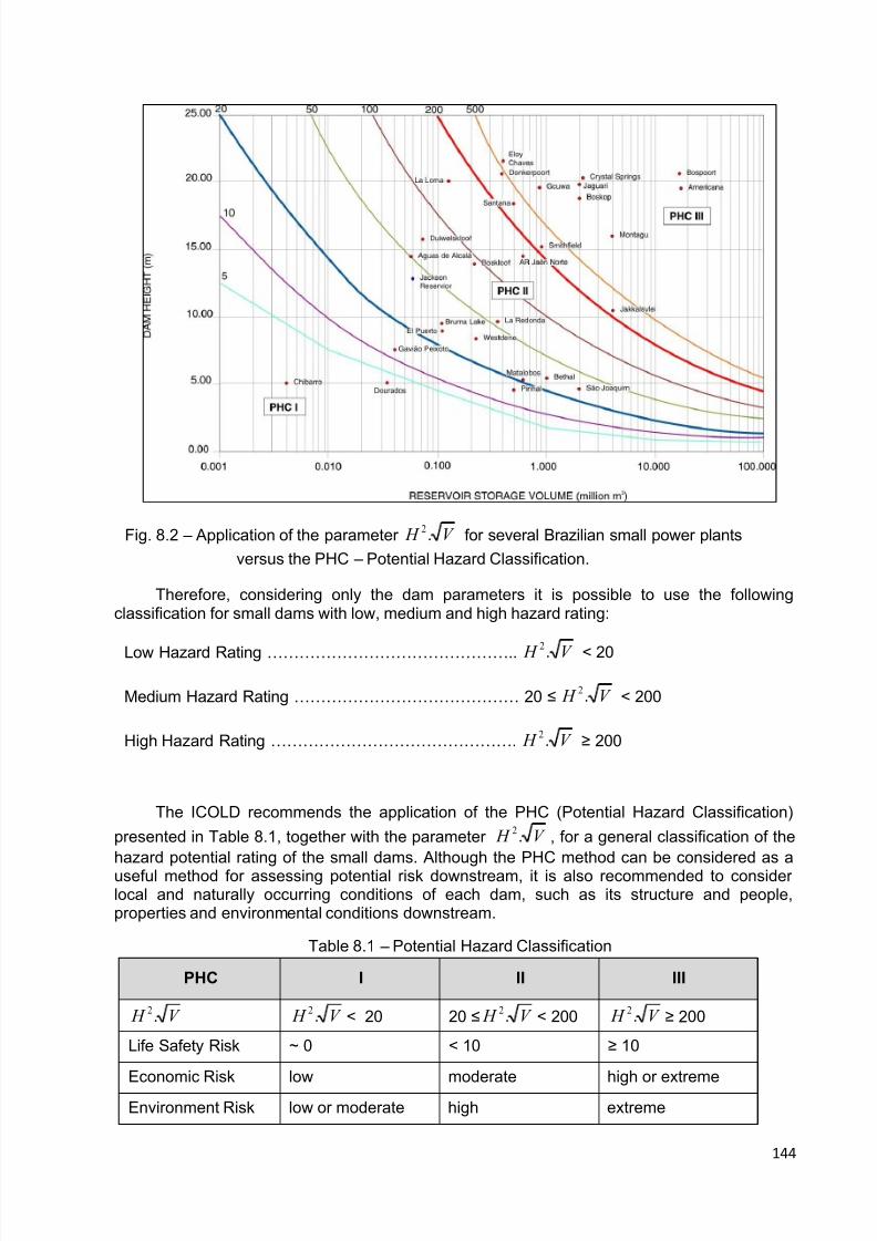
8/12/2019 ICOLD Small Dams Sept 2011
http://slidepdf.com/reader/full/icold-small-dams-sept-2011 144/149

8/12/2019 ICOLD Small Dams Sept 2011
http://slidepdf.com/reader/full/icold-small-dams-sept-2011 145/149
145
Social Disruption low (rural area) regional national
The PHC is related to the highest criterion. For example, a dam with V H .2 <200 butwith more than 10 people exposed to risk should be classified as PHC = III.
8.5 DAM SITE ACCESS DURING SEVERE STORMS
A very important point to be considered in an Emergency Action Plan for a small dam with ahigh hazard rating is the access conditions to the dam site during extreme floods. Particularlyfor dams located in mountainous region, it is usual to observe slope failures or broken bridgesduring severe storms, which can prevent people which are outside of the dam place to get to it.
It is important to analyze the behavior of the dam access during severe storms, in order todetect all possible problems that can occur along the access roads, and what can be done inorder to avoid them during new similar or worst climate conditions. For instance, in the case ofslope failures it is important to evaluate the amount of soil and rock to be removed, how longthis operation would take and what type of equipment are available in the nearby to do it.
When the existing bridges are not able to support great floods, the possibility of reinforcingthem with a more resistant structure like that shown in Figure 8.3 must be considered. This typeof bridge is being used in the south part of Brazil, and it can resist high floods after beingsubmerged for some hours.
Fig. 8.3 – Type of bridge in the south of Brazil, with a resistant concrete structure, that is able tosupport high floods underwater.
The possibility of rupture of a bridge like that one is negligible, based on the Brazilian practicalexperience with this type of bridge in a mountainous region in the Rio Grande do Sul State. Thistype of bridge has a structure of reinforced concrete that is sufficiently resistant, and it does notuse salient keep-body along the borders, in order to be able to remain submerged during greatfloods and come back to normal conditions right after that. The transit of vehicles through these
bridges can return to normality as soon as the high flood decreases.

8/12/2019 ICOLD Small Dams Sept 2011
http://slidepdf.com/reader/full/icold-small-dams-sept-2011 146/149
146
8.6 DAM BREAK AND INUNDATION MAP
The analytical requirements for an EAP include the information necessary to conduct dambreakanalyses and to prepare inundation maps. The process of developing a workable EAP mustnecessarily begin with the knowledge of what areas will be flooded as a result of a dam failure,so that the jurisdictions and agencies and individuals involved in the implementation of the EAPcan be identified.
The tools for identifying the areas flooded and developing the notification procedures areusually dambreak analyses and inundation mapping for large dams. Considering, therefore, thegreat number of small dams, such technology can be applied only for the small dams withextremely high hazard potential rating, using a more simplified way for the others small dams,as will be presented at the end of this item.
Several different inflow conditions may need to be investigated to determine the appropriatecondition prevailing at the time of a dam failure in order to ensure that the EAP includes allcommunities that need to be notified. A “fair weather” dam failure, that means reservoir atnormal full elevation, normal stream flow prevailing, is generally considered to have the mostpotential for human life loss, primarily due to the element surprise. However, a failure of a damduring flood flow conditions will result in flooding downstream areas to higher elevations thanduring “fair weather” failure.
Experience has shown that the emergency management agencies will use the inundation mapsto develop their evacuation procedures, using both the “fair weather” breach and also a failureduring a flood level approaching the inflow design flood. Usually basic or hydrological maps of1:10 000 scale are used for inundation line depiction.
One of the most thoroughly documented failures is the Teton Dam Failure, that took place onJune 5th of 1977, and the work presented by Graham/2008 [9] presents detailed signs of its
consequences and the water level hit by the flood. Downstream from the Teton dam, the rivergoes along a Canyon for approximately 8 kilometers (km), and then meanders through arelatively flat plain and divides into two forks about 7.4 km downstream from the end of thecanyon.
Based on the data about this accident, Figure 8.4 presents the estimated water leveldownstream of small dams with 5, 10 and 15 m high, after a dam break . Considering that theTeton dam had a canyon in the first 8 km, it is possible to conclude that in cases where thevalley is not so narrow, the water level would be below those plots. Anyway, these data will bevaluable in estimating the maximum water level downstream, with some safety factor alreadycomputed.
Thus for small dams with 5 to 15 m high the water level will be higher than 0.5 m, below that itis possible to consider that the damages will be minimum at the following distancesdownstream the dam:
Dam 5 m high ……………………………. 4.7 km Dam 10 m high ………………………….. 7.0 km Dam 15 m high ………………………….. 7.0 km
These data are important in order to show us that in the case of small dams, we usually have totake care of persons, structures, highways and industries located up to 5 to 7 km downstream,in case of a dam break.
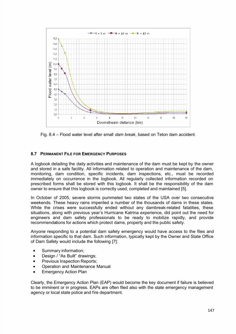
8/12/2019 ICOLD Small Dams Sept 2011
http://slidepdf.com/reader/full/icold-small-dams-sept-2011 147/149
147
Fig. 8.4 – Flood water level after small dam break , based on Teton dam accident.
8.7 PERMANENT FILE FOR EMERGENCY PURPOSES
A logbook detailing the daily activities and maintenance of the dam must be kept by the ownerand stored in a safe facility. All information related to operation and maintenance of the dam,
monitoring, dam condition, specific incidents, dam inspections, etc., must be recordedimmediately on occurrence in the logbook. All regularly collected information recorded onprescribed forms shall be stored with this logbook. It shall be the responsibility of the damowner to ensure that this logbook is correctly used, completed and maintained [5].
In October of 2005, severe storms pummeled two states of the USA over two consecutiveweekends. These heavy rains imperiled a number of the thousands of dams in these states.While the crises were successfully ended without any dambreak-related fatalities, thesesituations, along with previous year’s Hurricane Katrina experience, did point out the need forengineers and dam safety professionals to be ready to mobilize rapidly, and providerecommendations for actions which protect dams, property and the public safety.
Anyone responding to a potential dam safety emergency would have access to the files andinformation specific to that dam. Such information, typically kept by the Owner and State Officeof Dam Safety would include the following [7]:
Summary information;Design / “As Built” drawings; Previous Inspection Reports;Operation and Maintenance ManualEmergency Action Plan
Clearly, the Emergency Action Plan (EAP) would become the key document if failure is believedto be imminent or in progress. EAPs are often filed also with the state emergency management
agency or local state police and fire department.

8/12/2019 ICOLD Small Dams Sept 2011
http://slidepdf.com/reader/full/icold-small-dams-sept-2011 148/149
148
Realistically however, in many response situations, as concluded by Cox/2007 based onpractical experience, an engineer or inspector will not have quick access to these files. And insome cases, even when the files are available not all critical information may be included.
It is very important to arrive on site with the right equipment, as pointed out by Cox/2007 [7]. Itshould not be expected that the first engineer or inspector on site will come equipped to repair
problems, but the following is a list of equipment which might prove useful when responding atop dam safety emergency, and then need to be prepared previously:
Filed book and pencilsClip boardDigital camera (extra batteries)Cell phone (with important number of batteries);Measuring tapeFlashlight (extra batteries)Rain gear and umbrellaCalculator
Laptop (with wireless internet connection)Stake or ruler for staff gaugeGPS UnitTracer dye.
Since the collection of such equipment takes time, it is generally a good idea to preassemble a“ready bag” or plastic tube with all necessary equipment so that it is ready to be loaded into avehicle on short notice.
Personal safety gear such as high-visibility clothing, flotation devices and hard hats should beavailable.
8.8 EMERGENCY EXERCISING AND UPDATING
Emergency incidents at dams and dam failures are not common events. Training exercises arenecessary to maintain operation readiness, timeliness and responsiveness. This mayaccomplished through development and conduct of an emergency exercise program. It isrecommended that detailed guidelines on developing and implementing Emergency Action Planwill be used in these situations.
Warning and evacuation plans should be considered “living” documents, as pointed out by theBureau of Reclamation [1]. This means that:
1. They will never be completed;2. They should be reviewed not less than each five years for small dams;3. Review should include participation of personnel of the dam operating organization, and
local authorities when possible;4. All updates should be made promptly.
Changes that may frequently require revision and update of emergency action plans includechanges in personnel of involved organizations and changes in communications systems. As aminimum, review of office telephone numbers and appropriate personnel included in notificationflowcharts should be conducted.
During the review of warning and evacuating plan, a comprehensive evaluation of the adequacy
of the plan should be made as well.

8/12/2019 ICOLD Small Dams Sept 2011
http://slidepdf.com/reader/full/icold-small-dams-sept-2011 149/149
8.9 REFERENCES
[1] BURREC (1994) – “Emergency Action Planning Guidelines For Dams and Reservoirs”,
U.S. Department of the Interior, Bureau of Reclamation;
[2] ABADJIEV, C.B. (2009) – Personal contribution received from Bulgaria;[3] FEMA (2007) – “Emergency Action Planning for State Regulated High-Hazard Potential
Dams, Findings, Recommendations and Strategies”, FEMA 708, August 2007;
[4] LOPEZ, L.A., MARTINEZ, F.J.S., CORDBA, J.Y. (2004) – “The Emergency Action Plans
in Spain”, Annual Conference from the ASDSO – Association of State Dam SafetyOfficials, Sept 2004;
[5] SMEC (2007) – “Draft Guidelines for Managing Small Dams”, The Republic of Uganda – Appendix D, SMEC Australia Pty Ltd, Feb 2007;
[6] BADENHORST, D.B. (2004) – “Vygeboom Dam: Operation, Maintenance Manual andEmergency Plan”, South Africa;
[7] COX, C.W. (2007) – “Dam Emergency Response Suggestions for a Dam Safety
Engineer’s Toolkit and Checklist ”, Annual Conference from the ASDSO – Association ofState Dam Safety Officials, Sept 2007, Boston;
[8] JINBAO, S., LEI, L.,ZHAOSHENG, W., XUEHUI, P., SHICHEN, Z. (2007) – “Small Dam
Safety and Risk Management in China”, ICOLD 75 th Annual Meeting, Saint Petersburg,Russia;
[9] GRAHAM W J (2008) – “The Teton Dam Failure: Factors Affecting the Warning and