i&c signal interface - static.iter.orgstatic.iter.org/codac/pcdh7/folder...
TRANSCRIPT

PDF generated on 18-Mar-2013DISCLAIMER : UNCONTROLLED WHEN PRINTED – PLEASE CHECK THE STATUS OF THE DOCUMENT IN IDM
Technical Specification
I&C signal interface
This document addresses the following topics:Plant system I&C cubicle configurations.I&C signal cabling configurations.Mesh bonding for I&C signals.I&C signal standards.I&C signal interfacing with controllers. This technical document is a reference document associated to PCDH.
Approval Process Name Action AffiliationAuthor Journeaux J.- Y. 11-Jan-2013:signed IO/DG/DIP/CHD/CSD/PCICoAuthorReviewers Yonekawa I.
Wallander A. 17-Jan-2013:recommended21-Jan-2013:recommended
IO/DG/DIP/CHD/CSD/PCIIO/DG/DIP/CHD/CSD
Approver Thomas P. 18-Mar-2013:approved IO/DG/DIP/CHDDocument Security: level 1 (IO unclassified)
RO: Journeaux Jean-YvesRead Access AD: ITER, AD: External Collaborators, AD: Division - Control System Division - EXT, AD: Section -
CODAC - EXT, AD: Section - CODAC, project administrator, RO, LG: Cubicle configuration, LG: CODAC team
IDM UID
3299VTVERSION CREATED ON / VERSION / STATUS
11 Jan 2013 / 5.0/ Approved
EXTERNAL REFERENCE

PDF generated on 18-Mar-2013DISCLAIMER : UNCONTROLLED WHEN PRINTED – PLEASE CHECK THE STATUS OF THE DOCUMENT IN IDM
Change Log
Title (Uid) Version
Latest Status Issue Date Description of Change
I&C signal interface (3299VT_v5_0)
v5.0 Approved 11 Jan 2013
Version issued in scope of PCDH v7. Main changes:
Alignment with EDH part 4 v3.0 and removal of overlaps
Sections 4, 5
Clarification of plant system I&C HW signal interface
Section 2
I&C signal interface (3299VT_v4_4)
v4.4 Approved 09 Feb 2011
Version issued after external review of PCDH v6
I&C signal interface (3299VT_v4_3)
v4.3 Signed 05 Jan 2011
John Poole review for PCDH v6
I&C signal interface (3299VT_v4_2)
v4.2 Signed 03 Jan 2011
New version for review in scope of PCDH v6.
I&C signal interface (3299VT_v4_1)
v4.1 Signed 23 Sep 2010
Small changes / V4.0
I&C signal interface (3299VT_v4_0)
v4.0 Signed 23 Sep 2010
IEC 61000-5-2 introduced plus AEMC review

PDF generated on 18-Mar-2013DISCLAIMER : UNCONTROLLED WHEN PRINTED – PLEASE CHECK THE STATUS OF THE DOCUMENT IN IDM
I&C signal interface (3299VT_v3_1)
v3.1 Approved 29 Jan 2010
Update after PCDH v5.0 review
I&C signal interface (3299VT_v3_0)
v3.0 Signed 29 Jan 2010
Update after PCDH v5.0 review
I&C signal interface (3299VT_v2_1)
v2.1 Signed 28 Jan 2010
PCDH v5 review included
I&C signal interface (3299VT_v2_0)
v2.0 Signed 28 Jan 2010
PCDH v5 review included
I&C signal interface (3299VT_v1_4)
v1.4 Signed 28 Jan 2010
Version after official PCDH review
I&C signal interface (3299VT_v1_3)
v1.3 Signed 10 Dec 2009
PCDH figure change
I&C signal interface (3299VT_v1_2)
v1.2 Signed 10 Dec 2009
Update after comments taken in account
I&C signal interface (3299VT_v1_1)
v1.1 Signed 22 Oct 2009
Comments from Fabio and Lennart added
I&C signal interface (3299VT_v1_0)
v1.0 Signed 15 Oct 2009

Records of revisions
Revision Date Description Modified Pages
1.0 08/07/2009 First draft
1.1 01/07/2009 Version submitted to review by short committee The whole doc
1.4 22/10/2009 Version submitted to IO review The whole doc
1.5 19/11/2009 Quality review plus adds on earthing policy The whole doc
3.0 25/01/2010 Update after PVDH v5.0 review Whole doc
4.0 14/10/2010 Update for PCDH v6, CAPSIM review introduced Sections: 1.7, 1.8, 2.2, 3.3, 4.5
4.1 15/11/2010 Alignment with cabling rules Sections 4, 5
Alignment with EDH part 4 v3.0 and removal of overlaps
Sections 4, 55.0 31/08/2012
Clarification of plant system I&C HW signal interface
Section 2

TABLE of CONTENTS
1. INTRODUCTION .............................................................................................................................4
1.1. PCDH context...........................................................................................................................4
1.2. Document scope .......................................................................................................................4
1.3. Topics remaining to be addressed ..........................................................................................5
1.4. Acronyms..................................................................................................................................6
1.5. Glossary ....................................................................................................................................7
1.6. Reference documents...............................................................................................................7
2. PLANT SYSTEM I&C CUBICLES CONFIGURATIONS.............................................................8
2.1. Plant system I&C HW scope and interfaces .........................................................................8
2.2. I&C cubicle configuration types.............................................................................................9
2.3. Rules and guidelines applicable to I&C cubicle configuration .........................................10
3. I&C CONTROLLERS CONFIGURATIONS ................................................................................11
3.1. Slow controllers......................................................................................................................11
3.2. Fast controllers.......................................................................................................................12
4. I&C SIGNAL CABLING CONFIGURATIONS............................................................................13
4.1. I&C signals cabling schemas between PSE and I&C cubicles ..........................................13
4.2. Cabling rules and guidelines applicable between PSE and I&C cubicles ........................14
4.3. Cabling rules and guidelines applicable in between plant system I&C............................15
5. I&C SIGNAL EARTHING and CABLING PRACTICE for EMC...............................................16
5.1. Principles ................................................................................................................................16
5.2. Earthing into I&C cubicles ...................................................................................................16
5.3. Electrical isolation and earthing: schemas for I&C signals...............................................17
6. I&C SIGNALS STANDARDS ........................................................................................................24
7. I&C CUBICLE WIRING CONFIGURATION..............................................................................25
7.1. I&C controller obsolescence .................................................................................................25
7.2. 24 V DC power for I&C signals............................................................................................25
FIGURES
Figure 1-1: PCDH documents structure_________________________________________________________4Figure 2-1: Plant System I&C HW interfaces ____________________________________________________8Figure 2-2: Configurations proposed for I&C cubicles: ____________________________________________9Figure 3-1: S7-400 PLC with remote IO rack serial configuration ___________________________________11Figure 3-2: S7-400 PLC with remote IO rack star and serial configuration mixed. ______________________11Figure 3-3: example of fast controller hardware configuration _____________________________________12Figure 4-1: PSE direct connection ____________________________________________________________13Figure 4-2: PSE connection through I&C junction box. ___________________________________________13Figure 4-3: PSE connection for complex PSE.___________________________________________________14Figure 4-4: PSE connection through a plant system field-bus. ______________________________________14Figure 4-5: Illustration of 4.20, the link with a red cross is not recommended. _________________________15Figure 4-6: Illustration of 4.2 for PSE connection to different plant systems I&Cs ______________________15Figure 5-1: I&C signal transmission, sensor configuration with differential amplifier at receiver
level. _____________________________________________________________________17Figure 5-2: I&C signal transmission, sensor configuration with isolated receiver. ______________________17Figure 5-3: I&C signal transmission, sensor configuration with isolated source. _______________________18Figure 5-4: I&C signal transmission in truly differential configuration _______________________________18Figure 5-5: I&C signal cabling, sensor configuration without transmitter and with isolated receiver. _______19Figure 5-6: Alternative for an isolated sensor with a passive low-pass filter ___________________________19Figure 5-7: Optical transmission of single or multiplexed signals ___________________________________19Figure 5-8: Differential receiver at actuator end. ________________________________________________20Figure 5-9: Differential receiver plus galvanic isolation at actuator end. _____________________________20Figure 5-10: Galvanic isolation at I&C controller end. ___________________________________________20Figure 5-11: Configuration suitable for proportional valve control in harsh environments________________21Figure 5-12: Digital configuration with isolated receiver at controller end. ___________________________21Figure 5-13: Digital configuration with isolated sensor.___________________________________________21Figure 5-14: Digital configuration with isolated transmitter. _______________________________________22Figure 5-15: Digital configuration with isolated actuator. _________________________________________22Figure 5-16: Configuration for valve control in a harsh environment using compressed air. ______________22Figure 7-1: Connection of I/O through terminal blocks. ___________________________________________25

1. INTRODUCTION
1.1.PCDH contextThe Plant Control Design Handbook (PCDH) 1.6.1 defines methodology, standards, specifications and interfaces applicable to ITER Plant Systems Instrumentation & Control (I&C) system life cycle. I&C standards are essential for ITER to:
• Integrate all plant systems into one integrated control system.• Maintain all plant systems after delivery acceptance.• Contain cost by economy of scale.
PCDH comprises a core document which presents the plant system I&C life cycle and recaps the main rules to be applied to the plant system I&Cs for conventional controls, interlocks and safety controls. Some I&C topics will be explained in greater detail in dedicated documents associated with PCDH as presented in Figure 1-1. This document is one of them.
Core PCDH (27LH2V)Plant system control philosophyPlant system control Life CyclePlant system control specificationsCODAC interface specificationsInterlock I&C specificationSafety I&C specification
PCDH core and satellite documents: v7PS CONTROL DESIGN
Plant system I&C architecture (32GEBH)
Methodology for PS I&C specifications (353AZY)
CODAC Core System Overview (34SDZ5) INTERLOCK CONTROLS
Guidelines PIS design (3PZ2D2)
Guidelines for PIS integration & config.Management of local interlock functionsPIS Operation and Maintenance
I&C CONVENTIONSI&C Signal and variable naming (2UT8SH)
ITER CODAC Glossary (34QECT)
ITER CODAC Acronym list (2LT73V)
PS SELF DESCRIPTION DATASelf description schema documentation (34QXCP)
CATALOGUES for PS CONTROLSlow controllers products (333J33)
Fast controller products (345X28)
Cubicle products (35LXVZ)
Integration kit for PS I&C
PS CONTROL INTEGRATIONThe CODAC -PS Interface (34V362)
PS I&C integration plan (3VVU9W)
ITER alarm system management (3WCD7T)
ITER operator user interface (3XLESZ)
Guidelines for PON archivingPS Operating State management (AC2P4J)
Guidelines for Diagnostic data structure (354SJ3)PS CONTROL DEVELOPMENT
I&C signal interface (3299VT)
PLC software engineering handbook (3QPL4H)
Guidelines for fast controllers (333K4C)
CODAC software development environment (2NRS2K)
Guidelines for I&C cubicle configurations (4H5DW6)
CWS case study specifications (35W299)
NUCLEAR PCDH (2YNEFU)
OCCUPATIONAL SAFETY CONTROLSGuidelines for PSS design
Available and approvedExpected
Legend
This document
(XXXXXX) IDM ref.
I&C signal interface (3299VT)
Figure 1-1: PCDH documents structure
1.2.Document scopeI&C Signal interface in general mainly addresses the following topics:
1) Plant system I&C cubicle configurations.2) I&C signal cabling configurations.3) I&C signal earthing and cabling practices for EMC.4) I&C signal standards.5) I&C signal conditioning and powering.6) I&C cubicle wiring configurations7) I&C signal interfacing with controllers.
This document addresses points 1) to 5) (conditioning is not addressed since out of scope of PCDH); Points 6) and 7) are addressed by the document [RD4].Safety control configurations are out of scope of this document.Most of the standards which are proposed in this document were extracted and adapted to ITER I&C from working practices used in the design and documentation of other fusion facilities which are still in operation.Table 1 provides the full list of identifiers used in this document. The recommendations raised in this document as for the other PCDH satellite documents are mainly guidelines; some are rules, in such a
case they are identified by a star symbol.As a general rule, the release of this document, like all the documents associated with PCDH mentioned in Figure 1-1, will be followed by an immediate update of the core PCDH so that the core PCDH is a single document containing all the mandatory rules applicable to plant system I&C. In this way it will be easier for the reader to understand the requirements.
Table 1: Paragraph identifiers
AD Applicable DocumentGL Glossary itemRD Reference Document Rules referenced in core PCDH
1.3.Topics remaining to be addressedThe details of the following topics will be addressed in a next version of this document:
Sensor and actuator connections to controllers using a field-bus. Multiplexed transmission of signals.
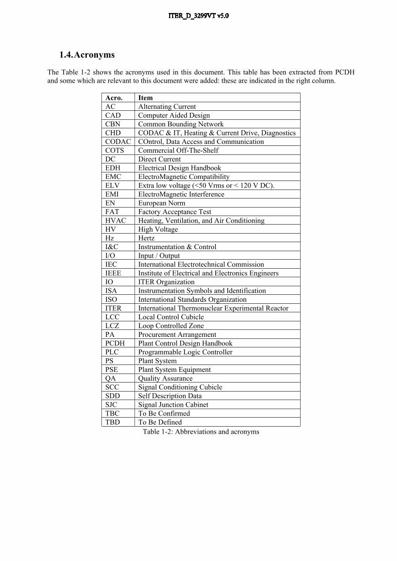
1.4.Acronyms
The Table 1-2 shows the acronyms used in this document. This table has been extracted from PCDH and some which are relevant to this document were added: these are indicated in the right column.
Acro. ItemAC Alternating CurrentCAD Computer Aided DesignCBN Common Bounding NetworkCHD CODAC & IT, Heating & Current Drive, DiagnosticsCODAC COntrol, Data Access and CommunicationCOTS Commercial Off-The-ShelfDC Direct CurrentEDH Electrical Design Handbook EMC ElectroMagnetic CompatibilityELV Extra low voltage (<50 Vrms or < 120 V DC).EMI ElectroMagnetic InterferenceEN European NormFAT Factory Acceptance TestHVAC Heating, Ventilation, and Air ConditioningHV High VoltageHz HertzI&C Instrumentation & ControlI/O Input / OutputIEC International Electrotechnical CommissionIEEE Institute of Electrical and Electronics EngineersIO ITER OrganizationISA Instrumentation Symbols and IdentificationISO International Standards OrganizationITER International Thermonuclear Experimental ReactorLCC Local Control CubicleLCZ Loop Controlled ZonePA Procurement ArrangementPCDH Plant Control Design HandbookPLC Programmable Logic ControllerPS Plant SystemPSE Plant System EquipmentQA Quality AssuranceSCC Signal Conditioning CubicleSDD Self Description DataSJC Signal Junction CabinetTBC To Be ConfirmedTBD To Be Defined
Table 1-2: Abbreviations and acronyms

1.5.Glossary CBN: see [AD2] definition. EMI - Electromagnetic Interference. is the degradation of the performance of a device,
equipment or system by an electromagnetic disturbance EMC - The usual definition (IEC) of this abbreviation is: “ElectroMagnetic Compatibility: The
ability of an equipment or system to function satisfactorily in its electromagnetic environment without introducing intolerable electromagnetic disturbances to anything in that environment”
I&C cables may be signal cables, field-bus cables or network cables. They may be copper or optical fibre. A signal cable may carry either analogue, digital or waveform signals. An I&C component may generate or use one or many signals.
I&C component. I&C component include sensors, actuators, controllers, PLCs, IOCs, servers, any central CODAC equipment and the associated software of all these equipment.
I&C cubicle. I&C cubicle is a local control cubicle, a signal conditioning cubicle or a combination of both.
I&C signal: is analogue, binary or waveform state or command information that comes on a physical wire from/to a plant system sensor or actuator to/from a I/O interface.
Local Control Cubicles (LCC). LCCs house the plant system I&C controllers. An LCC may house signal conditioning to improve integration of I&C equipment.
Signal Junction Cabinet (SJC). A signal junction cabinet is a box or cabinet dedicated to I&C signal cable interfaces between PSE and the plant system I&C cubicles.
Plant System Equipment (PSE). Plant system equipment is any plant system device which is controlled or monitored by the plant system I&C. They range from a single sensor/actuator up to a fully integrated set of components including embedded interfaces for powering, local controls, safety and interlocks. For example, a compressor or a power supply with associated auxiliaries provided by the equipment supplier. Plant system equipment may have local panels , local controller for local control or local monitoring, but no dedicated SCADA system.
Plant system I&C: see PCDH definition. The plant system I&C does not include PSEs. Remote I/O: A remote I/O is an I&C controller chassi dedicated to I/O interface only. The I/O
chassi is connected to the central CPU chassi through a fast multiplexed link. Signal Conditioning Cubicles (SCC). SCCs house the I/O interfaces dedicated to signal
conditioning. An SCC may include remote I/O, but there is no intelligence for controls in SCCs.
1.6. Reference documents1.6.1. Applicable documents
[AD1] Plant Control Design Handbook (PCDH). (27LH2V)[AD2] EDH Part 4: Electromagnetic Compatibility (EMC) (4B523E) [AD3] IO cabling rules (335VF9) [AD4] ITER Policy on EEE in Tokamak Complex (6ZX6S3)
1.6.2. Reference documents
[RD1] ITER catalogue for I&C products - Slow controllers PLC (333J63) [RD2] Guideline for Fast Controllers, I/O Bus Systems and Communication Methods between
Interconnected Systems (333K4C) [RD3] ITER Catalogue of I&C products - Fast Contollers (345X28)[RD4] I&C cubicle internal configuration (4H5DW6)

2. PLANT SYSTEM I&C CUBICLES CONFIGURATIONS
2.1. Plant system I&C HW scope and interfacesSee PCDH [AD1] for detailed definition of a plant system I&C.Any plant system I&C is interfaced physically and functionally to the Central I&C by functional and physical CODAC network interfaces. See PCDH for further details about Central I&C interfaces.In addition, the plant system I&C is interfaced to plant system equipment by physical and functional interfaces. It is assumed these interfaces are implemented by signals and field-buses. See Figure 2-1.
Central I&C: PBS 45, 46, 47, 48
CPU
Remote I/O
PS equipment
Central I&C networks: are specified in PCDH
I&C controller configured with CPU chassis and remote I/O chassis: are specified in PCDH and catalogues of products
Signal and filed-buses: scope of this document. In addition EDH part 4 [AD2], cabling rules [AD3] and ITER policy on EEE apply.
Plant system equipment interfaces for I&C controllers: are out of scope of PCDH
Procurement boundary
PS
I&C
bou
ndar
y
Figure 2-1: Plant System I&C HW interfaces
These signals and field-buses interfaces are connected to I&C controller signal interface boards installed in remote I/O chassis. See section 3 for further details. I&C controllers chassis are installed in I&C cubicles; the I&C cubicles are one of the deliverables to be procured in scope of the Procurement Arrangement (PA). This deliverable package is identified as [D18] in the PCDH, section 3.Following rules apply to this deliverable:Rules attached to the CODAC system design and related to signals and cubicles:
An I&C cubicle belongs to one and only one plant system I&C. This rule is required to get Self Description Data (SDD) consistent with the plant system I&C concept. See PCDH.
A plant system equipment signal is connected to one plant system I&C and only one. Same purpose as previous one.
Recommendation attached to the procurement scheme and related to signals and cubicles: No I&C cubicle sharing over several procurements. This recommendation is for simplification
of the procurement and clarification of responsibilities. It is assumed there some optimisation might be performed by IO after the hand-over of the procurement from the supplier to IO.

2.2.I&C cubicle configuration typesThis section aims at defining the different configurations which are proposed for I&C cubicles. These I&C cubicles are of two types:
Signal Conditioning Cubicles (SCC). SCCs house the I/O interface dedicated to signal conditioning. A SCC may include remote I/O, but there is no intelligence for controls in SCCs.
Local Control Cubicles (LCC). LCCs house the plant system I&C controllers. A LCC may house signal conditioning to improve integration of I&C equipment.
Figure 2-2: Configurations proposed for I&C cubicles:
Configuration1: The I/O interfaces (I/O cards) of the I&C controllers are connected to Plant System Equipment (PSE) through signal conditioning interfaces housed in an SCC. The length of LCC – SCC and SCC – PSE cables have to be compliant with signal levels regarding EMC.
SCC LCC
PSE1
1A1
PSE2
LCC + SCC
PSE1
1A1
PSE2
Configuration2: This configuration is similar to configuration 1, but LCC and SCC are merged in order to optimise the space allocation. Length of LCC/SCC– PSE cables have to be compliant with signal levels regarding EMC again.
Configuration3: In this configuration, the I&C controller of LCC is configured with a remote I/O chassis installed in the SCC. The link between the LCC controller and the remote I/O chassis may be fibre optic in the case of a long distance connection, strong EMI issues or any voltage isolation issue.
SCC + remote IO
LCC
PSE1
1A1
PSE2
LCC
Field bus
PSE1
1A1
PSE2
Configuration4: In this configuration, the PSE are connected to the I&C controller by a plant system I&C field-bus. The medium may be fibre optic. In this configuration, there is no need for signal conditioning at controller level.

2.3. Rules and guidelines applicable to I&C cubicle configuration
Segregation from safety: safety controls are housed in independent safety cubicles in order to get a clear segregation of safety controls. Specific Safety rules apply for these safety cubicles.
Interlocks: plant system interlock functions are preferably installed in Interlock cubicles but may share cubicles used for conventional control functions.
The cubicle location and configurations shall comply with the EMC policy [AD4] within the Tokamak complex.
All I&C cubicles shall be monitored for temperature, cooling and door state. The document [RD1] for enclosure configuration applies for I&C cubicle enclosure
configuration The document [RD4] for I&C cubicle internal configuration applies as a guideline for cubicle
manufacture.

3. I&C CONTROLLERS CONFIGURATIONS
3.1.Slow controllersThe document “ITER catalogue of PLC products” referenced [RD1] provides the details of hardware configurations of slow controllers.The policy for slow control is to connect the signals to standard remote I/O chassis connected to a CPU chassis. Several type of CPU are proposed to get some flexibility and adjust the CPU performance to the plant system need. For the highest range of PLC, the CPU chassis may be configured with several CPU boards. Scalability is achieved by adding additional chassis.PLC topologyThe connection of the remote IO chassis to the CPU rack may be as either serial, star or a combination of both, depending on the I&C cubicle configurations and relevant outcomes of the plant system I&C risk analysis if any.The remote I/O chassis distance to the CPU chassis is not considered to determine the controller topology: Only the link technology will change: copper cables for short distance and normal environment; fibre optic cables for long distance or harsh environments.
I/O BoardsThe central PLC CPU chassis may include I/O boards for S7-300 PLCs, but no I/O boards for S7-400 PLCs. No I/O boards from the S7-400 product line have been selected for the ITER catalogue firstly in order to reduce the range of ITER standards and secondly because these boards do not bring additional features compared to the equivalent S7-300 I/O boards.The PLC remote I/O chassis will be the same whatever the two PLC types, refer to [RD1] for details on products.
Next Rack
Figure 3-1: S7-400 PLC with remote IO chassis serial configuration
Switch
Other Rack
Figure 3-2: S7-400 PLC with remote IO chassis star and serial configuration mixed.

3.2.Fast controllersThe documents referenced [RD2] and [RD3] provide the details of technology and hardware configurations of fast controllers. The policy for fast controller’s topology is similar to slow controller’s policy, but with following
PXI, Compact PCI and PXI Express I/O boards will be used as the main, recommended items of the ITER Instrumentation and Control System Fast Controller catalogue.
A PXI Express chassis is used to carry the I/O boards. PXI Express I/O chassis is separated from the CPU chassis which will be a standard industrial
computer. Two systems are interconnected using a PCI Express link. Performance upgrades will be easier because the I/O chassis will never been touched; only the
industrial computer with CPU/Networking will be replaced, thus preserving the cabling from modifications and manipulation.
I/O:- PXI- CompactPCI- PXI Express (PCIe)
Example of 2 chassis- PXIe Chassis (hybrid)- PXIe Chassis (PCIe)
4U PICMG 1.3 chassis
1 Gb/s Ethernet
Optional10 Gb/s EthernetBus Extension
2 x PCI-Express x4
Figure 3-3: example of fast controller hardware configuration

4. I&C SIGNAL CABLING CONFIGURATIONS
4.1. I&C signals cabling schemas between PSE and I&C cubiclesI&C signal cabling addresses the electrical and optical connections which are required to transport I&C signals from the plant system equipment (PSE) to the I&C cubicles and between I&C cubicles. Following guidelines are applicable for plant system cabling:
There are four types of connection of PSE to I&C cubicles: direct connection, connection through a SJC, connection on a PSE interface and connection through a plant system field-bus. These four configurations can be mixed for flexibility.
Figure 4-1: PSE direct connection
This is the simplest way to connect PSE and I&C cubicles. I&C signal cables are shielded single or multi-twisted pairs cables. This configuration is suitable for PSE spread out in the vicinity of the plant system I&C cubicles without a high density of PSE.
In this configuration, PSE are first cabled to a Signal Junction Cabinet (SJC). Then the SJC is cabled to the plant system I&C cubicle. This configuration is preferred for the case of high density of PSE of the same signal range. In such a case similar signals are gathered in the same cable for facilitating on-site cabling.
PSE1
Shielded twisted pairs
I&C cubicle
PSE2
1A1
PSE3
PSE1
Shielded twisted pairs
I&C cubicle
PSE2
PSE3
Shilded multi-twisted pair
SJC
Figure 4-2: PSE connection through I&C junction box.

Figure 4-3: PSE connection for complex PSE. This configuration addresses complex PSE which require the operation of additional auxiliaries or specific embedded I&C. In such a case, the I&C signals are made available to be cabled to the I&C cubicle directly or through a SJC. This configuration is required in particular when power amplification of the control signals is required by the PSE. As for the previous configuration, similar signals are gathered in the same cable in order to facilitate on-site cabling.
Figure 4-4: PSE connection through a plant system field-bus.This connection addresses PSE connection to the plant system I&C controllers through a plant system I&C field-bus. Any field-bus can be selected provided it connects the IO standard controllers.
4.2.Cabling rules and guidelines applicable between PSE and I&C cubicles
Direct connections of I&C signals between PSE of the same plant system I&C are not recommended. This guideline aims to avoid any hidden common mode or dependence which could not be managed easily by the plant system I&C. If required by several plant PSE, associated data can be transmitted to the PSEs through the plant system I&C controllers. See Figure 4-5.
A particular PSE signal shall not be connected to different plant system I&Cs. If requested by several plant system I&Cs, the corresponding data shall be transmitted through the CODAC networks.
The I&C signals coming from PSEs are presented to I&C cubicles in such a way that high voltage insulation issues ( > 1 kV) are handled outside I&C cubicles. Deviations from this rule may be managed as exceptions for SCC equipped with remote I/O only.
Shielded multi-twisted pairs
PSE
I&C cubicle
I&C cubicle
1A1
PSE1
1A1
PSE2
1A1
PSE1
Field-bus

Figure 4-5: Illustration of section 4.2, the link with a red cross is not recommended.
4.3.Cabling rules and guidelines applicable in between plant system I&C Direct cabled connections of I&C signals from a plant system I&C to another plant system I&C
inside the same plant system or between two different plant systems are not allowed. The aim of this rule is to clarify the plant system I&C boundary and delivery. See Figure 4-6. If required such connections have to be considered as exceptions to PCDH. See PCDH exception management.
PSE1
I&C cubiclePlant system 1
I&C cubiclePlant system 2
Not allowed: link to be handled as exception to PCDH rules
Figure 4-6: Illustration of section 4.2 for PSE connection to different plant systems I&Cs
PSE1
I&C cubicle
PSE2
Not recommended: link to be handled by the PS I&C controller

5. I&C SIGNAL EARTHING and CABLING PRACTICE for EMC
5.1. Principles Fluxes created by high currents or magnetic field variations may interfere by inducing a voltage which is added directly to the signal being measured. Electrostatic shielding is ineffective in this situation. However, by using a twisted pair, the induced voltage will have opposite signs in adjacent twists and will therefore be balanced out. Consequently, the following rule applies:
All the electrical cables used for transport of I&C signals will be single or multiple twisted pairs. Exception to this rule may apply for high frequency and high voltage analogue signals transmitted on short distance. For such signals coaxial cables are recommended.
If there is a capacitance between a metal object whose voltage is changing rapidly and a signal conductor, a current will be generated in the signal conductor. The degree of coupling is proportional to the voltage variation as a function of time. The best solution to avoid such a current is to add an earthed electrostatic shield so that the capacitance is minimised. The currents then flow harmlessly to earth. Therefore, the following rules and guideline apply:
All I&C signal cables shall be shielded and the shield shall be connected to earth at both ends, except in the Loop Controlled Zone (LCZ) where a single earthing path shall be implemented, see [AD2].
For analogue signals multi pair I&C cables shall be composed of individually screened twisted pairs. Analogue signal multi-pair cables should be shielded by an overall shield too. This outer shield should be at least a braid, not an aluminium foil and shall be circumferentially (no pig-tail) bonded to the connector panels at both ends, with no breaks or gaps in their shields along their lengths. An aluminium foil should only be used to reduce crosstalk between internal pairs (protected by the same outer braid). Digital signal multi-pair cables may be shielded by an overall shield.
5.2. Earthing into I&C cubiclesFor I&C cubicles, one bonding strap is generally enough. But if electromagnetic interference sources are such that the highest frequencies they produce have wavelengths shorter than the greatest dimension of the cubicle, then multiple bonding straps should be used. In such a case, a typical distance between every bonding strap is one-tenth of the shortest wavelength of interest, with a minimum of 0,3 m for the distance. An earth is distributed in the I&C cubicles through an earth bar. This bar is directly connected to the CBN in the shortest way and is installed at the cubicle cable entrance, using plain copper saddle clamps. This cubicle earth bar is used to provide:
An electronic voltage reference for the I&C signals. The I&C earth is also used to reference the output of the isolation transformer for mains supply if any and the output of every power supply (24 V DC) for instrumentation. See section 7.2.
Signal-cable shielding. For I&C cables it is important that the shield should only be terminated once and then to earth. The termination of the shields must be made at the terminal blocks fitted to I&C cubicles for I&C earthing if connected to the I&C earth.
Cubicle metallic frame earthing. Every panel of the cubicle including doors shall be connected individually to the I&C earth.
I&C component earthing. Every metallic frame of components installed in I&C cubicles shall be connected individually to the I&C earth.
Safety earth: Even with a correct earth grid, protective earth cables (the PE “green-yellow cables”) coming with the main power cable shall be connected to the cubicle earth bar to insure in any case the workers safety at low frequency.

5.3.Electrical isolation and earthing: schemas for I&C signals
5.3.1. I&C signal transmission schemas for sensors with embedded transmitters delivering analogue signals.
This section presents three configurations which may be used for sensors that are connected to I&C controllers and which are equipped with a transmitter for signal amplification. The configuration to be chosen depends on the characteristics of the sensor, the controller input board and on the measurement environment. The differential receiver, isolated receiver and isolated source configuration should be used in normal environment (similar to the industry).
The full differential configuration shall be used for sensitive analogue signals within harsh environment.
Differential receiver configuration:The use of a differential amplifier at receiver level (see Figure 5-1) is a way to avoid any effects which may spoil the measurement. However the signal must stay within the amplifier input range. The differential amplifier may be a signal conditioner installed in the SCC or may be embedded in the I&C controller input board. Such a configuration assumes that the powering of the sensor plus transmitter is provided at sensor level and it is referenced to a local earth at that point. In the case where the differential amplifier is embedded in the I&C controller board, the negative point of the amplifier may be a common point for all channels of the board. This configuration is acceptable if the local earth which references the sensor signals is unique for all the board channels. It is then recommended that all sensors connected to the same I&C controller board must come from the same SJC.
TransmitterSensor I&C
controller
+
-
CBN
360° contacts
DC
0 v
0 v
0 v
Figure 5-1: I&C signal transmission, sensor configuration with differential amplifier at receiver level.
Isolated receiver configuration:By using galvanic isolation coupling, an isolation amplifier achieves the same effect as described above in addition to tolerating 1 kV. This galvanic isolation may be performed by a common conditioning device installed in the SCC and which is readily available in industry. This configuration is recommended when the signals connected on the same controller board are coming from broadly spread out locations. This configuration assumes that the power for the transmitter is provided at the sensor level. The guard of the insulating amplifier is optional. See Figure 5-2.
+-
I&C controller
TransmitterSensor
CBN360° contacts
DC
0 v
0 v0 v
Figure 5-2: I&C signal transmission, sensor configuration with isolated receiver.

Isolated source configuration:The voltage isolation is done at the sensor. This configuration is compliant with a wide distribution of sensors within the plant system, even when they are connected to the same I&C controller board. The power for the transmitters may be provided at either end. For I&C cubicle end, transmitter powering is achieved through the signal loop and then referenced to the I&C cubicle earth. The screen of the cable is earthed at both end and the guard (optional) of the insulating amplifier is connected to the I&C cubicle earth with a third wire, see Figure 5-3. The sensor / transmitter earth shield shown is optional.
I&C controller receiver
Sensor
CBN360° contacts
DC 0 v
Figure 5-3: I&C signal transmission, sensor configuration with isolated source.
Full differential configuration:A full differential signal transmission (differential receiver and transmitter, one side of the cable shield earthed) is the preferred configuration for sensitive analogue signals to ensure that the signal is transmitted without degradation even through a harsh environment. Resistors are introduced to limit the voltage gap with earth with respect to what is acceptable by the transmitter and receiver.
TransmitterSensor
I&C controller
+
-
CBN360° contacts
DC
2 resistors 1 MΩ ± 1%0 v
0 v
Figure 5-4: I&C signal transmission in truly differential configuration
5.3.2. I&C signal cabling schemas for sensors without any embedded transmitter.This section presents configurations which may be used for sensors that are connected to I&C controllers but which are not equipped with transmitters. These are commonly used for temperature measurements, e.g. thermocouples, PT100 and Cernox sensors, and also for magnetic flux measurements.Measurement signals provided by these sensors may be directly connected to suitable I&C controller boards, but are usually first conditioned by specific devices. In such a case, the conditioning devices are installed in the SCC.The cabling schema shown in Figure 5-5 applies. The voltage isolation is galvanic and may be embedded in the conditioning device. The voltage isolation is typically less than 1.5 kV and the conditioning device is powered from the I&C cubicle.

Sensor+-
I&C controller
CBN
360° contacts 0 v
Figure 5-5: I&C signal cabling, sensor configuration without transmitter and with isolated receiver.
Obviously, the third wire (“guard wire”) in Figure 5-5 is not necessary if the common mode voltage at low frequency is maintained at a low value, in the 10 mV or 100 mV range, or if the shielded cable is short (less than 100 m).
Even with a correct connection to earth, a passive input filter is recommended. For instance, for a usual thermocouple, 2 resistors of 4.7 kΩ, 2 common mode capacitors of 100 pF (±5% in NPO or COG) connected to I&C ground and a 47 µF tantalum cap (in differential mode). See Figure 5-6.
+-
CBN
360° contacts
Low pass filter
0 v
Sensor
I&C controller
Figure 5-6: Alternative for an isolated sensor with a passive low-pass filter
5.3.3. I&C analogue signal cabling schemas for sensors with optical transmissionThe two following signal transmission configuration is not supported by CODAC standards but may be suitable to deal with EMI or high voltage issues.The configuration illustrated in Figure 5-7, relies on conversion of the electric signal provided by the sensor into an optical signal transmitted by a fibre optic cable. This configuration makes it possible to transmit multiplexed signals on the same medium. The same functionality may be achieved using standard ITER hardware for a remote I/O configuration with a fibre optic link between the remote I/O chassis and I&C controller.
ReceiverSensor (s) I&C controller
F.O.Transmitter
DCDC
CBN
0 v 0 v
Figure 5-7: Optical transmission of single or multiplexed signals
Any way a great attention has to be paid to check the ambient magnetic induction before to install a DC/DC converter. Up to 10 mT, any Switch Mode Power Supply can work properly. From 10 to 30 mT, its reliability is degraded (due to increase of the current ripple). Over 30 mT, a possibly spectacular failure may occur in few minutes. In addition, the commercial receivers (without complementary shield) may be upset over 500 V of electrical fast transient in burst (EFT/B), according to the IEC 61000-4-4 standard.

5.3.4. I&C signal cabling schemas for actuators with embedded receivers supplied by analogue signals.
The configurations suitable for analogue actuator signal transmission are similar to those proposed for the sensors. The techniques proposed for sensors in section 5.3.1 are therefore also suitable for actuators.
Differential receiver at actuator end; see Figure 5-8. Differential receiver plus galvanic isolation; see Figure 5-9. Galvanic isolation at I&C controller end; see Figure 5-10.
The optical transmission proposed in Figure 5-7 for sensors is acceptable for actuators for the same reasons, but is not supported by CODAC standardisation.In some cases (valves for examples), the actuator may be remotely controlled and powered through a pneumatic control, see Figure 5-11.
Actuator Transmitter
I&C controller+
-
CBN CBN
360° contacts
DC0 v
0 v0 v
Figure 5-8: Differential receiver at actuator end.
+-
I&C controller
TransmitterActuator
CBN CBN
360° contacts
DC
0 v0 v
0 v
Figure 5-9: Differential receiver plus galvanic isolation at actuator end.
I&C controller receiverActuator
CBN CBN360° contacts
DC
0 v
Figure 5-10: Galvanic isolation at I&C controller end.

Compressed air (dry and oil free)
I&C controller
`Position: Plastic tube
Pneumatic positioner
Control: plastic tube
Figure 5-11: Configuration suitable for proportional valve control in harsh environments
On the example illustrated above, the valve is remotely controlled using a position feedback loop through air signals. The pneumatic positioner is located in a protected area.
5.3.5. I&C signal cabling schemas for sensors delivering digital signals.Even if EMI issues are less important for digital signals than for analogue signals, the same policy applies for signal transmission. Two configurations are considered for digital inputs: one where the DC power supply for signal powering is located at the sensor end and the other one where the power supply is located at I&C cubicle end.
An opto-coupler for electrical isolation (1 kV) is required at the I&C cubicle for both configurations. This opto-coupler will be integrated to the cabling interface within I&C cubicles as a standard ITER component. See [RD4] for further details.
The configuration with DC power supply at sensor end (isolated receiver) is preferred for complex PSE. The digital sensor is connected to the positive outlet of this power supply (not the outlet referenced to earth).
I&C controllerDC
Sensor
Opto-coupler
DC
CBN
0 v
Figure 5-12: Digital configuration with isolated receiver at controller end.
The configuration with isolated sensor may be used. In this case, the DC power supply used to power the input signal coming from the sensor shall be separate from that used to power the I&C controller input. This additional DC power supply is located in the I&C cubicle, is a ELV for safety reasons and is referenced on 0V outlet to the local earth. The digital sensor is connected to the positive outlet of the power supply (not the outlet referenced to earth). The opto-coupler remains needed for the protection of the controller in case of loss of voltage isolation at sensor side. Recommended voltage is 24 V DC for this power supply, but other voltages may be used if compliant with above recommendations.
I&C controller
DC
Sensor
Opto-coupler
DC
CBN
0 v
Figure 5-13: Digital configuration with isolated sensor.

5.3.6. I&C signal cabling schemas for actuators controlled by digital signals.Similar configurations as those used for digital sensors will be used for digital actuators, with similar comments: The configuration with DC power supply at the actuator end (isolated receiver) is preferred for complex PSE.A configuration with an isolated actuator may be used. In this case, the DC power supply used to power the output signal going to the actuator shall be separate from that used to power the I&C controller output. This additional DC power supply is located in the I&C cubicle and for safety reasons and supplies a ELV.
I&C controllerDC
Actuator or pre-actuator Opto-
coupler
CBN
0 v
Figure 5-14: Digital configuration with isolated transmitter. DC power supply on actuator end.
I&C controller
DC Opto-coupler
Actuator or pre-actuator
CBN
0 v
Figure 5-15: Digital configuration with isolated actuator. DC power supply on controller end.
In harsh environments a configuration with a pneumatic actuator controlled by an electric pre-actuator is recommended for the valves.
Plastic tube Compressed air (dry and oil free)
I&C controller
Electrical powered valve
Pneumatic powered valve
Figure 5-16: Configuration for valve control in a harsh environment using compressed air.
5.3.7. I&C signal cabling schemas with field buses and serial links.For connection plant system equipment, any field-bus may be selected provided it can connect the IO standard controllers. [AD2] and [AD3] apply for cabling.

5.4. Summary for I&C signals earthing and cabling The [AD2] EDH part 4 applies for EMC. The [AD3] cabling rules applies for cabling. All I&C signal cables shall be shielded and the shield shall be connected to earth at both ends,
except in the Loop Controlled Zone (LCZ) where a single earthing path shall be implemented. All analogue and digital signals shall be cabled with twisted pairs as far as high frequency
losses are not a concern. Otherwise, coaxial cables are needed. For analogue signals, configurations with differential amplifiers, isolation receivers or full
differential provide the best results against EMI. ELV (<50 Vrms or < 120 V DC) voltage (24 V DC recommended) shall be used for digital
signals.

6. I&C SIGNALS STANDARDSThe main target of standard definitions for I&C signals is standardisation of I&C controller hardware to satisfy cost saving and maintenance issues. These standard hardware products will be detailed in separate and specific documents such as catalogues of standard products for slow, fast, interlock and safety controllers. This section gives the inputs which will be used for this selection in addition to those related to cubicle configurations proposed in previous sections of this document.It is assumed that any I&C signal which would not comply with these I&C signal standards would be handled by a signal conditioning device to be installed in the SCC cubicle. For this reason, the I&C signal standards listed in this section are to be considered as only guidelines for signals coming to SCC and as rules for signals directly connected to the I&C controllers or connected through remote I/O devices.Measurements/controls transmitted through field-buses from sensors/actuators are not considered in this section, since they have no impact on the selection of the controller hardware.
6.1. Analogue signalsSensors- Voltage range: 0V to +10V unipolar, -5V to +5V bipolar, -10V to +10V bipolar.- Current range: 4mA to 20mA (16mA span). Signal polarity: positive with respect to signal common.
Actuators- Output Current: 4mA to 20mA (16mA span). Signal polarity: positive with respect to signal
common. Load resistance: 500 max. Preferred 250 .- Output voltage: 0V to +10V unipolar or: -10V to +10V bipolar.
6.2. Digital signalsFor sensors and actuators:- Signal logic: positive for process control, negative for fail safe logics (interlocks and safety
controls)- Range: 24V DC referenced to plant system I&C cubicle earth. Maximum current depends on the
galvanic isolation interface.
6.3. T sensors- Resistance thermometers: Pt100, 4 wires.- Thermocouples: type K, type N.A passive low-pass input filter may be recommended for any T sensor.
6.4. Pneumatic signals- Range: 0.2 to 1 bar for the I/P converters of pneumatic proportional valves.- 0 to 6-8 bars for on/off valves.

7. I&C CUBICLE WIRING CONFIGURATION
7.1. I&C controller obsolescenceI&C controllers are supposed to be upgraded during the life span of ITER. In order to ease hardware replacement, standard terminal blocks shall be used within the LCC for I/O wiring within the LCC and I/O cabling outside LCC . These terminal blocks shall be connected to the I/O boards by standard strap cables.These terminal blocks are supposed to be kept during the controller upgrade in order to limit the hardware upgrade to the controller hardware replacement only, avoiding any re-cabling of the cables entering the LCC.This assumes that the new controller I/O boards will be compatible with the previous I/O wiring; This is often the case for industrial controllers and new products from the same supplier. If not, the strap cables would be changed for a new one fitted to the terminal block on one side and to the I/O boards on the other. See [RD4] for further information on terminal blocks for I&C cubicles.
7.2. 24 V DC power for I&C signalsDistribution of 24V DC is provided within SCC and LCC for powering of I/O of PLC, fast controllers, PIS and PSS and signal conditioning devices. Following recommendations apply:
Supply the analogue I/O and digital I/O from separate and dedicated 24 V DC power supplies in order to avoid any interference on analogue signals created by digital switching.
The decision to supply the interlocks I/O by separate and dedicated 24 V DC power supply or not shall be the result of a risk analysis of a common mode failure in the case of common 24 V DC use.
The 0 V of every DC power supply output shall be referenced to the I&C cubicle earth. The 24 V DC power supplies shall be provided with an electronic limitation on supplied
current. This will be adapted to what is needed to power the I/O with a safety margin of 20 %. If required, several 24 V DC power supplies will be used. If so, the design of the 24 V distribution will take into account the failure of one power supply and the impact that this will have on the plant system.
Every output of a DC power supply in the I&C cubicles shall be monitored. This monitoring shall be performed at a point beyond any protection systems such as a fuses or circuit breakers of the DC power distribution (details TBD).
The distribution of DC power shall be done through a separate dedicated terminal block.
I&C controller
Terminal block
Strap cable
Figure 7-1: Connection of I/O through terminal blocks.
