©ian sommerville 2000software engineering, 6th edition. chapter 9 slide 1 formal specification l...
TRANSCRIPT
©Ian Sommerville 2000 Software Engineering, 6th edition. Chapter 9 Slide 1
Formal Specification
Techniques for the unambiguous specification of software
©Ian Sommerville 2000 Software Engineering, 6th edition. Chapter 9 Slide 2
Formal methods Formal specification is part of a more general
collection of techniques that are known as ‘formal methods’
These are all based on mathematical representation and analysis of software
Formal methods include• Formal specification
• Specification analysis and proof
• Transformational development
• Program verification
©Ian Sommerville 2000 Software Engineering, 6th edition. Chapter 9 Slide 3
Acceptance of formal methods Formal methods have not become mainstream
software development techniques as was once predicted• Other software engineering techniques have been successful at
increasing system quality. Hence the need for formal methods has been reduced
• Market changes have made time-to-market rather than software with a low error count the key factor. Formal methods do not reduce time to market
• The scope of formal methods is limited. They are not well-suited to specifying and analysing user interfaces and user interaction
• Formal methods are hard to scale up to large systems
©Ian Sommerville 2000 Software Engineering, 6th edition. Chapter 9 Slide 4
Use of formal methods Formal methods have limited practical
applicability Their principal benefits are in reducing the
number of errors in systems so their mai area of applicability is critical systems
In this area, the use of formal methods is most likely to be cost-effective

©Ian Sommerville 2000 Software Engineering, 6th edition. Chapter 9 Slide 5
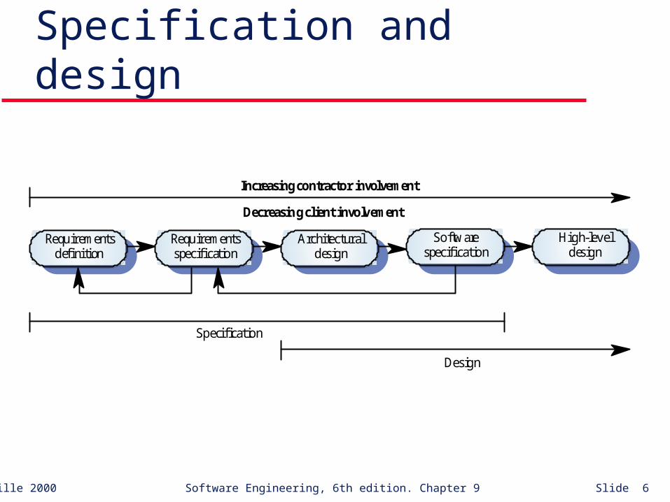
Specification in the software process Specification and design are inextricably
intermingled. Architectural design is essential to structure a
specification. Formal specifications are expressed in a
mathematical notation with precisely defined vocabulary, syntax and semantics.
©Ian Sommerville 2000 Software Engineering, 6th edition. Chapter 9 Slide 6
Specification and design
Architecturaldesign
Requirementsspecification
Requirementsdefinition
Softwarespecification
High-leveldesign
Increasing contractor involvement
Decreasing client involvement
Specification
Design

©Ian Sommerville 2000 Software Engineering, 6th edition. Chapter 9 Slide 7
Specification in the software process
Requirementsspecification
Formalspecification
Systemmodelling
Architecturaldesign
Requirementsdefinition
High-leveldesign
©Ian Sommerville 2000 Software Engineering, 6th edition. Chapter 9 Slide 8
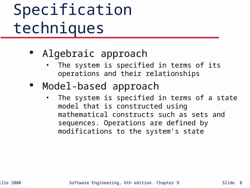
Specification techniques Algebraic approach
• The system is specified in terms of its operations and their relationships
Model-based approach• The system is specified in terms of a state model that is
constructed using mathematical constructs such as sets and sequences. Operations are defined by modifications to the system’s state

©Ian Sommerville 2000 Software Engineering, 6th edition. Chapter 9 Slide 9
Formal specification languages
©Ian Sommerville 2000 Software Engineering, 6th edition. Chapter 9 Slide 10
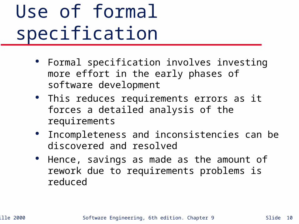
Use of formal specification Formal specification involves investing more
effort in the early phases of software development This reduces requirements errors as it forces a
detailed analysis of the requirements Incompleteness and inconsistencies can be
discovered and resolved Hence, savings as made as the amount of rework
due to requirements problems is reduced
©Ian Sommerville 2000 Software Engineering, 6th edition. Chapter 9 Slide 11
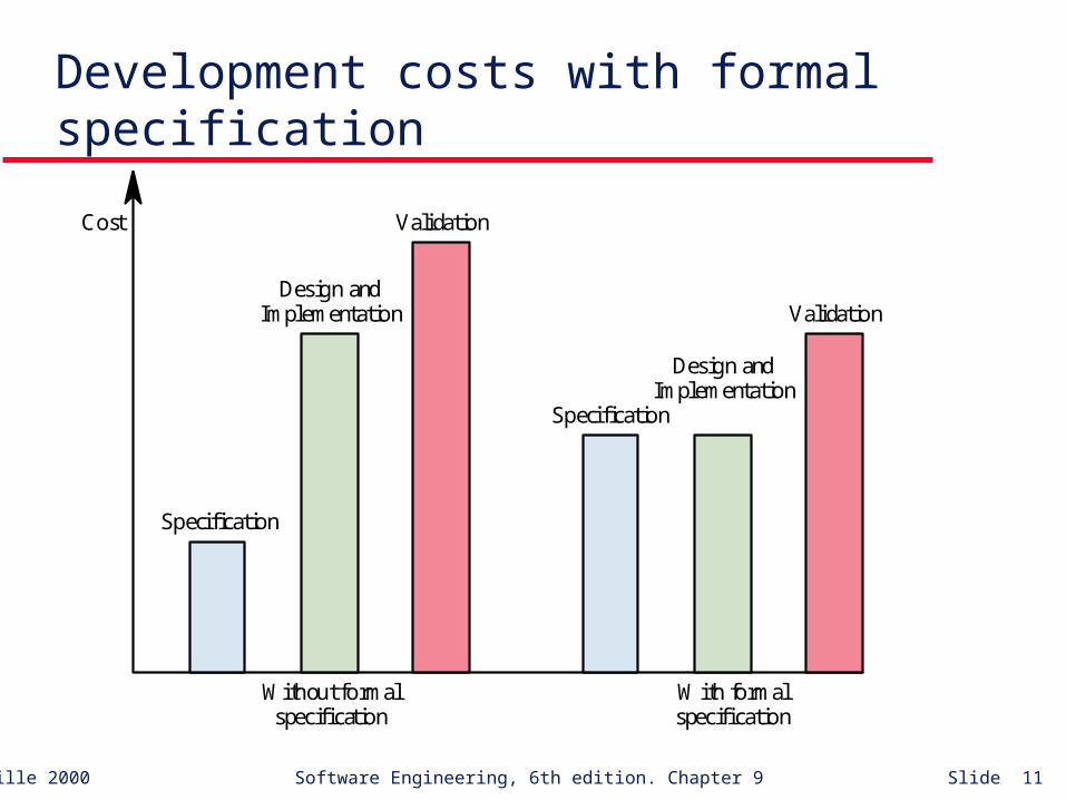
Development costs with formal specification
Specification
Design andImplementation
Validation
Specification
Design andImplementation
Validation
Cost
Without formalspecification
With formalspecification

©Ian Sommerville 2000 Software Engineering, 6th edition. Chapter 9 Slide 12
Interface specification Large systems are decomposed into subsystems with
well-defined interfaces between these subsystems Specification of subsystem interfaces allows
independent development of the different subsystems Interfaces may be defined as abstract data types or
object classes The algebraic approach to formal specification is
particularly well-suited to interface specification

©Ian Sommerville 2000 Software Engineering, 6th edition. Chapter 9 Slide 13
Sub-system interfaces
Sub-systemA
Sub-systemB
Interfaceobjects

©Ian Sommerville 2000 Software Engineering, 6th edition. Chapter 9 Slide 14
The structure of an algebraic specification
sort < name >imports < LIST OF SPECIFICATION NAMES >
Informal descr iption of the sor t and its oper ations
Operation signatures setting out the names and the types ofthe parameters to the operations defined over the sort
Axioms defining the oper ations o ver the sor t
< SPECIFICATION NAME > (Gener ic Parameter)

©Ian Sommerville 2000 Software Engineering, 6th edition. Chapter 9 Slide 15
Specification components Introduction
• Defines the sort (the type name) and declares other specifications that are used
Description• Informally describes the operations on the type
Signature• Defines the syntax of the operations in the interface and their
parameters
Axioms• Defines the operation semantics by defining axioms which
characterise behaviour

©Ian Sommerville 2000 Software Engineering, 6th edition. Chapter 9 Slide 16
Systematic algebraic specification Algebraic specifications of a system may be
developed in a systematic way• Specification structuring.
• Specification naming.
• Operation selection.
• Informal operation specification
• Syntax definition
• Axiom definition
©Ian Sommerville 2000 Software Engineering, 6th edition. Chapter 9 Slide 17
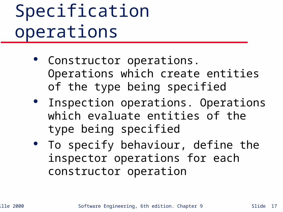
Specification operations Constructor operations. Operations which create
entities of the type being specified Inspection operations. Operations which evaluate
entities of the type being specified To specify behaviour, define the inspector
operations for each constructor operation

©Ian Sommerville 2000 Software Engineering, 6th edition. Chapter 9 Slide 18
Operations on a list ADT Constructor operations which evaluate to sort List
• Create, Cons and Tail
Inspection operations which take sort list as a parameter and return some other sort• Head and Length.
Tail can be defined using the simpler constructors Create and Cons. No need to define Head and Length with Tail.

©Ian Sommerville 2000 Software Engineering, 6th edition. Chapter 9 Slide 19
List specification
Head (Create) = Undefined exception (empty list)Head (Cons (L, v)) = if L = Create then v else Head (L)Length (Create) = 0Length (Cons (L, v)) = Length (L) + 1Tail (Create ) = CreateTail (Cons (L, v)) = if L = Create then Create else Cons (Tail (L), v)
sort Listimports INTEGER
Defines a list where elements are added at the end and removedfrom the front. The oper ations are Create, which brings an empty listinto existence, Cons, which creates a new list with an added member,Length, which evaluates the list size, Head, which evaluates the frontelement of the list, and Tail, which creates a list by removing the head from itsinput list. Undefined represents an undefined value of type Elem.
Create ListCons (List, Elem) ListHead (List) ElemLength (List) IntegerTail (List) List
LIST ( Elem )

©Ian Sommerville 2000 Software Engineering, 6th edition. Chapter 9 Slide 20
Recursion in specifications Operations are often specified recursively Tail (Cons (L, v)) = if L = Create then Create
else Cons (Tail (L), v)• Cons ([5, 7], 9) = [5, 7, 9]
• Tail ([5, 7, 9]) = Tail (Cons ( [5, 7], 9)) =
• Cons (Tail ([5, 7]), 9) = Cons (Tail (Cons ([5], 7)), 9) =
• Cons (Cons (Tail ([5]), 7), 9) =
• Cons (Cons (Tail (Cons ([], 5)), 7), 9) =
• Cons (Cons ([Create], 7), 9) = Cons ([7], 9) = [7, 9]

©Ian Sommerville 2000 Software Engineering, 6th edition. Chapter 9 Slide 21
Interface specification in critical systems
Consider an air traffic control system where aircraft fly through managed sectors of airspace
Each sector may include a number of aircraft but, for safety reasons, these must be separated
In this example, a simple vertical separation of 300m is proposed
The system should warn the controller if aircraft are instructed to move so that the separation rule is breached

©Ian Sommerville 2000 Software Engineering, 6th edition. Chapter 9 Slide 22
A sector object Critical operations on an object representing a
controlled sector are• Enter. Add an aircraft to the controlled airspace
• Leave. Remove an aircraft from the controlled airspace
• Move. Move an aircraft from one height to another
• Lookup. Given an aircraft identifier, return its current height

©Ian Sommerville 2000 Software Engineering, 6th edition. Chapter 9 Slide 23
Primitive operations It is sometimes necessary to introduce additional
operations to simplify the specification The other operations can then be defined using
these more primitive operations Primitive operations
• Create. Bring an instance of a sector into existence
• Put. Add an aircraft without safety checks
• In-space. Determine if a given aircraft is in the sector
• Occupied. Given a height, determine if there is an aircraft within 300m of that height

Sector specification
Enter (S, CS, H) = if In-space (S, CS ) then S exception (A ircraft already in sector) elsif Occupied (S, H) then S exception (Height conflict) else Put (S, CS, H)
Leave (Create, CS) = Create exception (A ircraft not in sector)Leave (Put (S, CS1, H1), CS) = if CS = CS1 then S else Put (Leave (S, CS), CS1, H1)
Move (S, CS, H) = if S = Create then Create exception (No aircraft in sector) elsif not In-space (S, CS) then S exception (A ircraft not in sector) elsif Occupied (S, H) then S exception (Height conflict) else Put (Leave (S, CS), CS, H)
-- NO-HEIGHT is a constant indicating that a valid height cannot be returned
Lookup (Create, CS) = NO-HEIGHT exception (A ircraft not in sector)Lookup (Put (S, CS1, H1), CS) = if CS = CS1 then H1 else Lookup (S, CS)
Occupied (Create, H) = falseOccupied (Put (S, CS1, H1), H) = if (H1 > H and H1 - H Š 300) or (H > H1 and H - H1 Š 300) then true else Occupied (S, H)
In-space (Create, CS) = falseIn-space (Put (S, CS1, H1), CS ) = if CS = CS1 then true else In-space (S, CS)
sort Sectorimports INTEGER, BOOLEAN
Enter - adds an aircraft to the sector if safety conditions are satisfedLeave - removes an aircraft from the sectorMove - moves an aircraft from one height to another if safe to do soLookup - Finds the height of an aircraft in the sector
Create - creates an empty sectorPut - adds an aircraft to a sector with no constraint checksIn-space - checks if an aircraft is already in a sectorOccupied - checks if a specified height is available
Enter (Sector, Call-sign, Height) SectorLeave (Sector, Call-sign) SectorMove (Sector, Call-sign, Height) SectorLookup (Sector, Call-sign) Height
Create SectorPut (Sector, Call-sign, Height) SectorIn-space (Sector, Call-sign) BooleanOccupied (Sector, Height) Boolean
SECTOR
©Ian Sommerville 2000 Software Engineering, 6th edition. Chapter 9 Slide 25
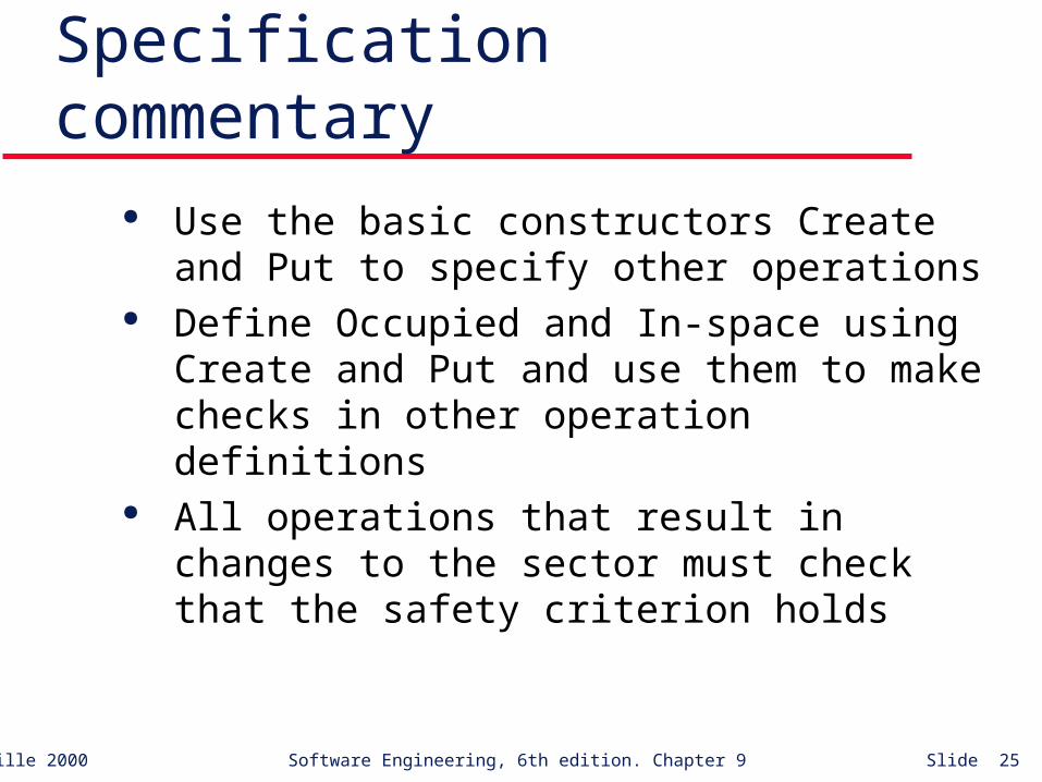
Specification commentary Use the basic constructors Create and Put to
specify other operations Define Occupied and In-space using Create and
Put and use them to make checks in other operation definitions
All operations that result in changes to the sector must check that the safety criterion holds

©Ian Sommerville 2000 Software Engineering, 6th edition. Chapter 9 Slide 26
Behavioural specification Algebraic specification can be cumbersome when the
object operations are not independent of the object state
Model-based specification exposes the system state and defines the operations in terms of changes to that state
The Z notation is a mature technique for model-based specification. It combines formal and informal description and uses graphical highlighting when presenting specifications
©Ian Sommerville 2000 Software Engineering, 6th edition. Chapter 9 Slide 27
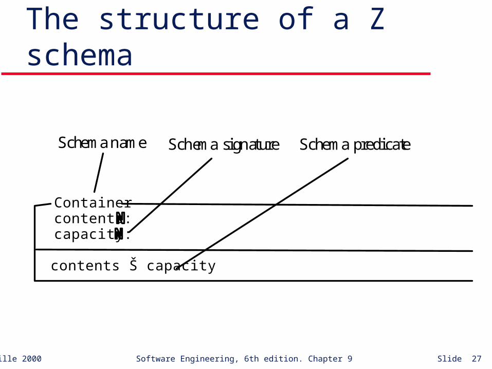
The structure of a Z schema
contents Š capacity
Containercontents: capacity:
Schema name Schema signature Schema predicate
©Ian Sommerville 2000 Software Engineering, 6th edition. Chapter 9 Slide 28
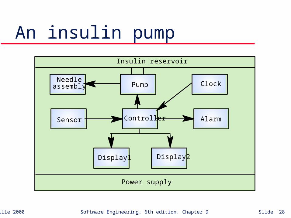
An insulin pump
Needleassembly
Sensor
Display1 Display2
Alarm
Pump Clock
Power supply
Insulin reservoir
Controller
©Ian Sommerville 2000 Software Engineering, 6th edition. Chapter 9 Slide 29
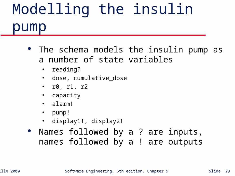
Modelling the insulin pump The schema models the insulin pump as a number
of state variables• reading?
• dose, cumulative_dose
• r0, r1, r2
• capacity
• alarm!
• pump!
• display1!, display2!
Names followed by a ? are inputs, names followed by a ! are outputs

©Ian Sommerville 2000 Software Engineering, 6th edition. Chapter 9 Slide 30
Schema invariant Each Z schema has an invariant part which
defines conditions that are always true For the insulin pump schema it is always true that
• The dose must be less than or equal to the capacity of the insulin reservoir
• No single dose may be more than 5 units of insulin and the total dose delivered in a time period must not exceed 50 units of insulin. This is a safety constraint (see Chapters 16 and 17)
• display1! shows the status of the insulin reservoir.
©Ian Sommerville 2000 Software Engineering, 6th edition. Chapter 9 Slide 31
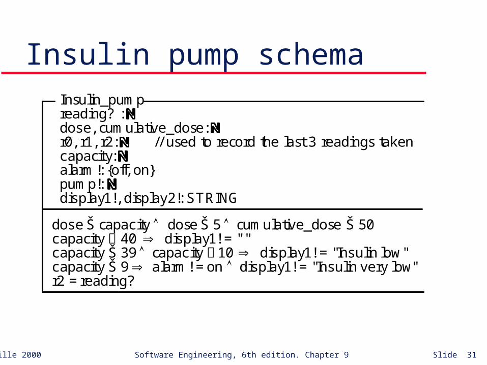
Insulin pump schemaInsulin_pumpreading? : dose, cumulative_dose: r0, r1, r2: // used to record the last 3 readings takencapacity: alarm!: {off, on}pump!: display1!, display2!: STRING
dose Š capacity dose Š 5 cumulative_dose Š 50capacity 40 display1! = " "capacity Š 39 capacity 10 display1! = "Insulin low"capacity Š 9 alarm! = on display1! = "Insulin very low"r2 = reading?

©Ian Sommerville 2000 Software Engineering, 6th edition. Chapter 9 Slide 32
The dosage computation The insulin pump computes the amount of insulin
required by comparing the current reading with two previous readings
If these suggest that blood glucose is rising then insulin is delivered
Information about the total dose delivered is maintained to allow the safety check invariant to be applied
Note that this invariant always applies - there is no need to repeat it in the dosage computation

©Ian Sommerville 2000 Software Engineering, 6th edition. Chapter 9 Slide 33
DOSAGE schemaDOSAGEInsulin_Pump
(dose = 0 (
r1 r0) ( r2 = r1)) (( r1 > r0) (r2 Š r1)) (( r1 < r0) ((r1-r2) > (r0-r1)))
) dose = 4 ( (( r1 Š r0) (r2=r1)) (( r1 < r0) ((r1-r2) Š (r0-r1))) ) dose =(r2 -r1) * 4 (
(( r1 Š r0) (r2 > r1)) (( r1 > r0) ((r2 - r1) (r1 - r0)))
))capacity' = capacity - dosecumulative_dose' = cumulative_dose + doser0' = r1 r1 ' = r2

©Ian Sommerville 2000 Software Engineering, 6th edition. Chapter 9 Slide 34
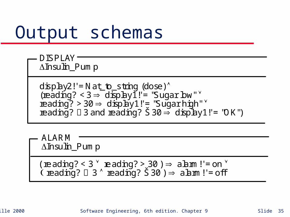
Output schemas The output schemas model the system displays
and the alarm that indicates some potentially dangerous condition
The output displays show the dose computed and a warning message
The alarm is activated if blood sugar is very low - this indicates that the user should eat something to increase their blood sugar level
©Ian Sommerville 2000 Software Engineering, 6th edition. Chapter 9 Slide 35
Output schemasDISPLAYInsulin_Pump
display2!' = Nat_to_string (dose) (reading? < 3 display1!' = "Sugar low" reading? > 30 display1!' = "Sugar high" reading? 3 and reading? Š 30 display1!' = "OK")
ALARMInsulin_Pump
( reading? < 3 reading? > 30 ) alarm!' = on reading? 3 reading? Š 30 ) alarm!' = off
©Ian Sommerville 2000 Software Engineering, 6th edition. Chapter 9 Slide 36
Schema consistency It is important that schemas are consistent.
Inconsistency suggests a problem with the system requirements
The INSULIN_PUMP schema and the DISPLAYare inconsistent• display1! shows a warning message about the insulin reservoir
(INSULIN_PUMP)
• display1! Shows the state of the blood sugar (DISPLAY)
This must be resolved before implementation of the system