i j e e volume 5 • number 1 • january-june 2013 pp. 9 … · rectangular microstrip antenna...
TRANSCRIPT
Effect of Slits and Parasitic Strip on RectangularMicrostrip Antenna - A Comparative Study
Nagraj Kulkarni1*, and S. N. Mulgi2
1,2Department of PG Studies and Research in Applied Electronics, Gulbarga University,Gulbarga-585106, Karnataka, India
Abstract: In this paper, a comparative study is made between the microstrip antenna consisting of a parasitic strip around theradiating patch and slits on the ground plane with respect to a conventional rectangular microstrip antenna designed for thesame resonant frequency. The proposed antenna operates between 3.2 to 10.6 GHz and gives five independent frequencybands and shows virtual size reduction of 5.28 %. The antenna is excited by microstripline feed arrangement at the center. Apeak gain of 5.26 dB is achieved with broadside and linearly polarized radiation characteristic. The experimental and simulatedresults of the antenna are in good agreement with each other. The design concept of the antenna is described and experimentalresults are presented and discussed. This antenna may find applications in wireless interoperability microwave access(WiMax), C and X band microwave communication systems.
Keywords: Microstrip antenna, slits, parasitic strip, high gain.
Serials Publications, ISSN : 0973-7383
1. INTRODUCTION
In recent years the microstrip antennas (MSAs) have attainedvery significant place in modern communication systems dueto their inherent attractive features like light weight, lowprofile, easy installation, low fabrication cost, compatibilitywith other microwave and millimeter wave components,conformability to curved surfaces [1] etc. The microstripantenna designers strived hard to put forth many methodsand techniques such as cutting slots of different geometrieslike triangular, bow-tie, rectangular, square ring, annular ringetc. on the radiating patch [2-7], use of corner truncatedpatches, implementing parasitic strips, use of stubs andshorts on the patches [ 8-10] etc. are used to achieve dual,triple and multiband antennas. It is the need of the hour toselect the antenna which suits for a particular application.Hence a novel geometry of rectangular microstrip antennahas been proposed consisting of a simple slits and a parasiticstrip that can be used for a specific application. This kind ofstudy is found to rare in the literature. By varying theparameters of parasitic strip and slits on the ground plane,there is freedom to the designer to achieve even betterantenna results.
2. DESIGNING
The low cost glass epoxy substrate material of area A × B,thickness h = 0.16 cm and dielectric constant �r = 4.2 is usedto fabricate the proposed antenna. The artwork of theantenna is sketched using computer software Auto CAD toachieve better accuracy. Photolithography process is usedto fabricate the antenna.
I J E E Volume 5 • Number 1 • January-June 2013 pp. 9-12
*Corresponding author: E-mail: [email protected]
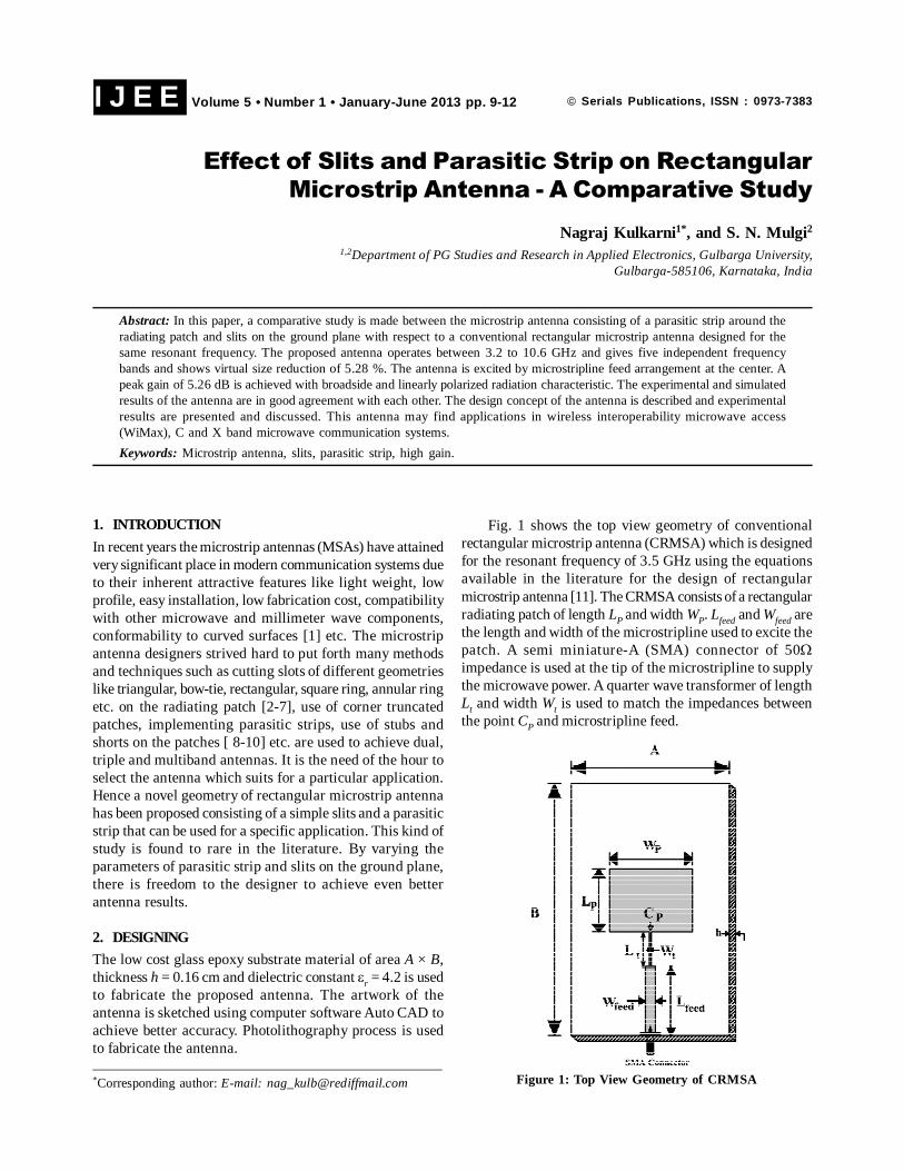
Fig. 1 shows the top view geometry of conventionalrectangular microstrip antenna (CRMSA) which is designedfor the resonant frequency of 3.5 GHz using the equationsavailable in the literature for the design of rectangularmicrostrip antenna [11]. The CRMSA consists of a rectangularradiating patch of length LP and width WP. Lfeed and Wfeed arethe length and width of the microstripline used to excite thepatch. A semi miniature-A (SMA) connector of 50�impedance is used at the tip of the microstripline to supplythe microwave power. A quarter wave transformer of lengthLt and width Wt is used to match the impedances betweenthe point CP and microstripline feed.
Figure 1: Top View Geometry of CRMSA
10
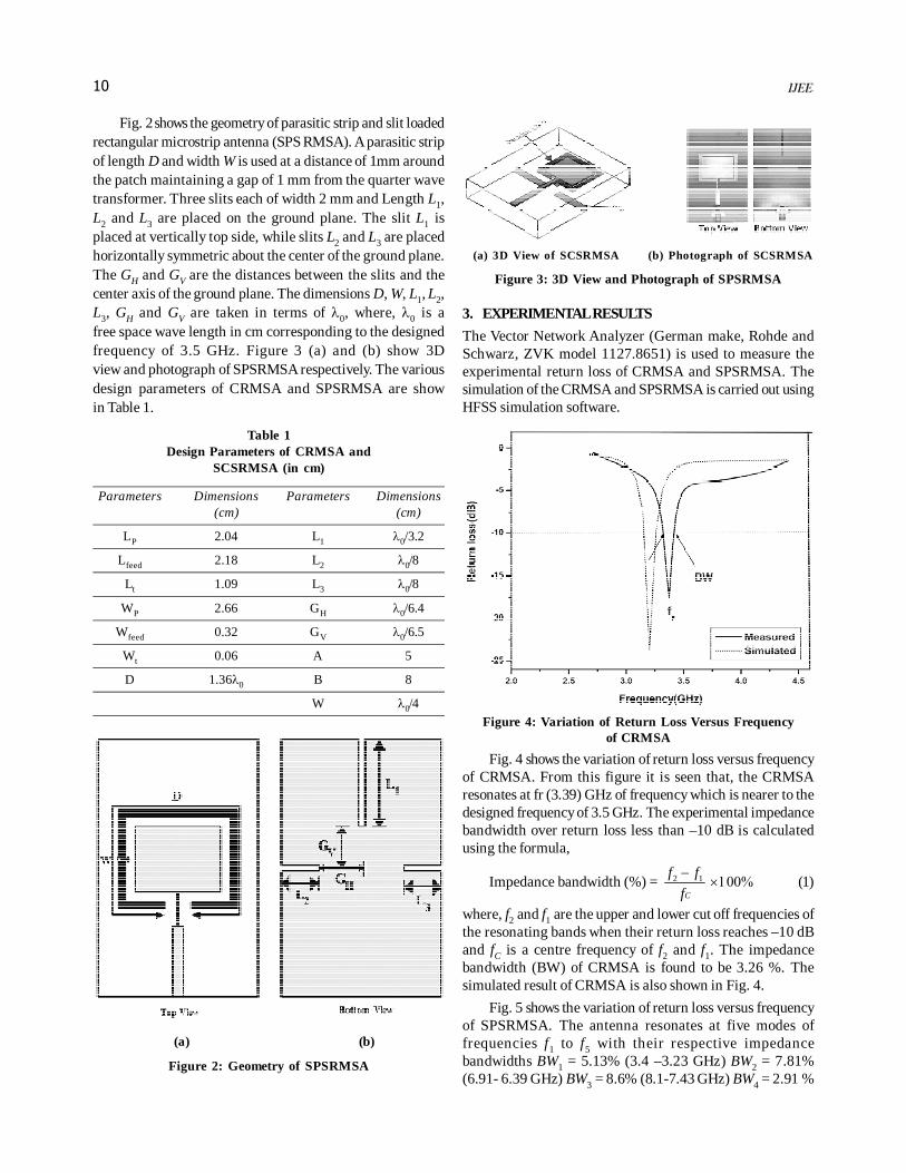
Fig. 2 shows the geometry of parasitic strip and slit loadedrectangular microstrip antenna (SPS RMSA). A parasitic stripof length D and width W is used at a distance of 1mm aroundthe patch maintaining a gap of 1 mm from the quarter wavetransformer. Three slits each of width 2 mm and Length L1,L2 and L3 are placed on the ground plane. The slit L1 isplaced at vertically top side, while slits L2 and L3 are placedhorizontally symmetric about the center of the ground plane.The GH and GV are the distances between the slits and thecenter axis of the ground plane. The dimensions D, W, L1, L2,L3, GH and GV are taken in terms of �0, where, �0 is afree space wave length in cm corresponding to the designedfrequency of 3.5 GHz. Figure 3 (a) and (b) show 3Dview and photograph of SPSRMSA respectively. The variousdesign parameters of CRMSA and SPSRMSA are showin Table 1.
Table 1Design Parameters of CRMSA and
SCSRMSA (in cm)
Parameters Dimensions Parameters Dimensions(cm) (cm)
LP 2.04 L1 �0/3.2
Lfeed 2.18 L2 �0/8
Lt 1.09 L3 �0/8
WP 2.66 GH �0/6.4
Wfeed 0.32 GV �0/6.5
Wt 0.06 A 5
D 1.36�0 B 8
W �0/4
(a) (b)
Figure 2: Geometry of SPSRMSA
(a) 3D View of SCSRMSA (b) Photograph of SCSRMSA
Figure 3: 3D View and Photograph of SPSRMSA
3. EXPERIMENTAL RESULTS
The Vector Network Analyzer (German make, Rohde andSchwarz, ZVK model 1127.8651) is used to measure theexperimental return loss of CRMSA and SPSRMSA. Thesimulation of the CRMSA and SPSRMSA is carried out usingHFSS simulation software.
Figure 4: Variation of Return Loss Versus Frequencyof CRMSA
Fig. 4 shows the variation of return loss versus frequencyof CRMSA. From this figure it is seen that, the CRMSAresonates at fr (3.39) GHz of frequency which is nearer to thedesigned frequency of 3.5 GHz. The experimental impedancebandwidth over return loss less than –10 dB is calculatedusing the formula,
Impedance bandwidth (%) = 2 1
C
f f
f
�������� (1)
where, f2 and f1 are the upper and lower cut off frequencies ofthe resonating bands when their return loss reaches –10 dBand fC is a centre frequency of f2 and f1. The impedancebandwidth (BW) of CRMSA is found to be 3.26 %. Thesimulated result of CRMSA is also shown in Fig. 4.
Fig. 5 shows the variation of return loss versus frequencyof SPSRMSA. The antenna resonates at five modes offrequencies f1 to f5 with their respective impedancebandwidths BW1 = 5.13% (3.4 –3.23 GHz) BW2 = 7.81%(6.91- 6.39 GHz) BW3 = 8.6% (8.1-7.43 GHz) BW4 = 2.91 %

11
(9.06- 8.8 GHz) and BW5 = 11.8 % (10.6-9.42 GHz). The firstband BW1 is due to the fundamental resonance of the patchand the bands BW2 to BW5 are due to the use of slits on theground plane. The enhancement of gain of each operatingbands is mainly due to the use of parasitic strip around thepatch. Further it is noted that, the resonant mode of primaryband BW1 of SPSRMSA shifts to 3.15 GHz when comparedto the resonant mode fr of CRMSA. This shows the virtualsize reduction of about 5.28 % when compared to the size ofCRMSA. The simulated result of SPSRMSA is also shownin Fig. 5.
Figure 5: Variation of Return Loss Versus Frequencyof SPSRMSA
The co-polar and cross-polar radiation patterns ofCRMSA and SPSRMSA measured in their operating bandsare shown in Fig 6 and 7 respectively. From these figures, itcan be seen that, the patterns are broadside and linearlypolarized.
The gain of CRMSA and SPSRMSA is calculated usingthe absolute gain method given by the relation,
(G)dB = 010log ( ) 20log4
rt
t
PG dB dB
P R
� � �� �� �� � � ��� �� �(2)
where, Gt is the gain of the pyramidal horn antenna and R isthe distance between the transmitting antenna and theantenna under test (AUT). The power received by AUT, ‘Pr’and the power transmitted by standard pyramidal hornantenna ‘Pt’ are measured independently. The maximum gainobtained for CRMSA measured in BW is found to be 0.9 dBand the peak gain of SPSRMSA is found to be 5.26 dB in itsprimary band BW1. Hence the novel geometry of SPSRMSAincreases the gain by nearly 5.84 times when compared tothe gain of CRMSA and decreases the half power beamwidth(HPBW) from 1060 to 700 as shown in Fig 6 and 7. Thecomparative applications of the CRMSA and SPSRMSA arelisted in Table 2.
Table 2Comparative Results of CRMSA and SPSRMSA
Parameter CRMSA SPSRMSA
Resonating modes 1 5
BW WiMax -
BW1 - WiMax
BW2 to BW5 - Applications in C and Xband microwave communication
systems
Frequency ratio - 2
Gain 0.9 dB 5.26 dB
HPBW 106º 70º
Virtual size reduction - 5.28%
Figure 6: Radiation Pattern of CRMS Measuredat 3.39 GHz
Figure 7 : Radiation Pattern of SPSRMSA Measuredat 3.39 GHz
4. CONCLUSION
From this detailed comparative study, it is concluded that,SPSRMSA, which is constructed by placing a parasitic striparound the patch and slits on the ground plane of CRMSA,is quite capable in enhancing the gain from 0.9 dB to 5.26 dBwhich is nearly 5.84 times more and decreases the HPBWfrom 106º to 70º when compared to the gain and HPBW of

12
CRMSA. The insertion of three slits reduces the virtual sizeof the antenna by 5.28 % and makes the antenna to operatefor five independent frequency bands between 3.2 to 10.6GHz retaing the primary band BW1. The radiationcharacteristics of CRMSA and SPSRMSA are broadside andlinearly polarized. The proposed antenna has simplegeometry and construction using low cost glass epoxysubstrate material. The SPSRMSA may be used for wirelessinteroperability microwave access (WiMax), C and X bandmicrowave communication systems .
Acknowledgements
The authors would like to thank the Dept. of Science &Technology (DST), Govt. of India, New Delhi, for sanctioningVector Network Analyzer to this Department under FIST project.
References[1] G. Kumar and K. P. Ray, “Broadband Microstrip Antennas”,
MA : Artech House, Norwood, (2003).
[2] A.A. Eldek., A.Z. Elsherbeni, and C.E. Smith, “Characteristicsof Bow-tie Slot Antenna with Tapered Tuning Stubs forWideband Operation”, Progress in ElectromagneticResearch PIER 49, (2004), pp. 53-69.
[3] Jia-Yi Sze, Chung-I G. Hsu, and Sheng-Chin Hsu , “Studiesof Small Dualband Annular-Ring Slot Antenna with A Pairof Implanted Spur-Like Slits”, Microwave Opt. Technol Lett,49, No.7 (2007), pp. 1578-1581.
[4] Kin-Lu Wong, Jian -Yi Wu and Chun - Kun Wu, “A CircularlyPolarized Patch - Loaded Square-slot Antenna”, Microwaveand Optical Technology Letters, 23, No.6 (1999), 363-365.
[5] M. Elsdon, A. Sambell, S. C. Gao, and Y. Qin, “Planar-FedCompact Circular Polarized Microstrip Antenna withTriangular-Slot Loading”, Microwave Opt. Technol Lett, 41,No.3 (2005), pp. 226-228.
[6] S. Sadat,., M. Fardis., F. Geran, and G. Dadashzadeh, “ACompact Microstrip Square-Ring Slot Antenna for UWBApplications”, Progress In Electromagnetic Research PIER67, (2007), pp. 173-179.
[7] F.J Wang, and J. S .Zhang, “Wideband Cavity backed patchantenna for PCS/IMT2000/2.4 GHz WLAN,” Progress InElectromagnetic Research PIER 74, (2007), 39-46.
[8] Dong-Hyuk Choi and Seong-Ook Park, “Active IntegratedAntenna Using T-Shaped Microstip-Line-Fed SlotAntenna”, Microwave Opt. Technol Lett, 48, No.2 (2006),pp. 367-370.
[9] K.P. Ray. and Deepti Das Krishna, “Compact DualBand Suspended Semicircular Microstrip Antenna withHalf U Slot”, Microwave Opt. Technol Lett, 48, Oct. (2006),pp. 2021-2024,
[10] J. A. Tirado-Mendez, H. Jardon - Aguilar and F. Iturbide -Sanchez, “Application of the Defected Microstrip Structureas a Tuning Technique for Rectangular Printed Antennas”,Microwave Opt. Echnol Lett, 48 (2006), pp. 370-373.
[11] Jui-Han Lu and Kin Lu Wong, “Single Feed CircularlyPolarized Equilateral Triangular Microstrip Antenna with aTuning Stub”, IEEE Trans. Ant and Propagat, 48 (2000).pp. 1869-1872,
[12] Theodore G. Vasiliadis and George D. Sergiadis, “WidebandPrinted Dipole Antenna Parasitically Enhanced withOver-an-Octave Bandwidth. Dual-Band Variant for WLANApplications”, Microwave Opt. Technol Lett, 48 (2006),pp. 370-373.
[13] Yuan Li, R. Chair, K. M. Luk, and K. F. Lee, “ShortedWideband Low-Profile Patch Antenna with two ShortingPins”, Microwave Opt. Technol Lett, 41 (2004), pp. 135-137.
[14] I.J Bahl and P. Bhartia, “Microstrip Antennas”, ArtechHouse, New Delhi, (1980).