i-flow 6000 series - peak scientific
TRANSCRIPT

i-Flow 6000 SeriesUser Manual
Copyright © Peak Scientific Instruments Ltd 2021 — i-Flow 6000 Series User Manual Rev 15 RSID 175 PN UM00018 EN copy —30/11/2021

Page 2
Contents
Change History 3How to use this Manual 3Introduction 4Technical Description 5Basic Concept 5i-Flow 6000 Model Number Breakdown 6Warranties and Liabilities 7Warranty & Liability Coverage 7Safety Notices 9EU Declaration of Conformity 10Environmental Declaration 11Technical Specification 12Unpacking 14Installation 15Generator Environment 15Generator 16General Dimensions 16Inlet / Outlet Connections 17Unit Controls 17Compressed Air Quality 18Class 1 – Particulate 18Class 2 – Water 18Class 1 – Oil 18Electrical Connection 20Recommended Piping Layout 21Commissioning & Safe Start-Up Sequence 22Normal Operation 23Safe Isolation Process 23Service Requirements 24Service Schedule 24Peak Protected 25Cleaning 26

Page 3
Change HistoryRev Comment Name Date3 Declarations Update L. Couttie 03/03/2017
4 Correction L. Couttie 26/09/2017
5 Declarations Update L. Couttie 10/10/2017
6 Declarations Update L. Couttie 16/01/2018
7 Declarations Update L. Couttie 15/01/2019
8 Update to Peak Gas Generation Branding L. Couttie 26/09/2019
9 Air Quality Update L. Couttie 10/12/201910 Declarations Update L. Couttie 22/10/202011 Declarations Update L. Couttie 04/11/202012 Declarations Update L. Couttie 10/11/202013 Declarations Update L. Couttie 18/12/2020
14 Declarations Update D.Lai 12/10/2021
How to use this Manual
This manual is intended for end users and has been written as a reference document where you can skip to the relevant information.
Users can refer to the contents page to find the relevant information.
Please review each of the following sections carefully.
Thank you for selecting Peak Gas Generation to meet your gas generation needs, and should you require any further assistance or support please do not hesitate to contact Peak Gas Generation or the Peak Partner from which you purchased your generator.

Page 4
Introduction
The Peak Gas Generation i-Flow 6000 Generator is designed to cater for a wide variety of industrial and scientific applications. Your generator will have been carefully selected to meet your specific pressure, flow, and purity requirements, if you have any questions regarding the sizing of your system please do not hesitate to contact Peak Gas Generation or the Peak Partner from which you purchased your Generator.
Peak Gas Generation is a Trading Name of Peak Scientific Instruments Ltd. All Peak Gas Generation products are manufactured by Peak Scientific Instruments Ltd.

Page 5
Technical DescriptionBasic ConceptThe i-Flow is a modular range of Carbon Molecular Sieve (CMS) nitrogen gas generators, that operate based on Pressure Swing Adsorption (PSA) technology. Essentially this requires two separate columns or “beds” of granular carbon pellets.
The unit requires a compressed air supply to operate, ultimately works on very similar principles to many standard air filtration / drying products. The inlet compressed air is passed into the first “bed”, as the air passes across the carbon bed the oxygen is adsorbed, allowing the nitrogen to carry on through the bed for collection and further use. After a certain time the online carbon bed will become saturated with oxygen so the control system will operate various valves to bring the second carbon bed online. Whilst the second bed comes online, the first bed is vented to atmosphere to release the adsorbed oxygen and regenerate the bed in preparation for the next cycle. This will continue to alternate and repeat until the user stops consuming nitrogen.
Should the demand for nitrogen be less than the rated output flow, or indeed should the demand stop, the generator will automatically go into ECO Mode and the front panel LED will illuminate. In ECO mode the changeover of the columns is suspended which will stop the consumption of inlet compressed air. The control system will automatically detect when the demand resumes and the generator will start to produce nitrogen again.
General ConstructionThe range consists of 10 different product sizesm, demonstrated below:
The front end cabinet, control system and valves are consistent across the range. To increase the outlet capacity, as you go up the range of generators, additional banks of CMS columns will be added. (Note: for 6 to 10 banks additional vent valves and silenc-ers are required and are fitted to the rear of the CMS columns)
Base unit with minimum single bank of dual CMS columns.
Base unit with maximum 10 banks of dual CMS columns.

Page 6
i-Flow 6000 Model Number Breakdown
01 1 Bank02 2 Banks03 3 Banks04 4 Banks05 5 Banks06 6 Banks07 7 Banks08 8 Banks09 9 Banks10 10 Banks
0 None - Basic Unit1 i-Flow - % Oxygen Analyser2 i-Flow - PPM Oxygen Analyser3 Inlet/Outlet Filter - No Oxygen Analyser4 Inlet/Outlet Filter - % Oxygen Analyser5 Inlet/Outlet Filter - PPM Oxygen Analyser6 i-Flow Lab - % Oxygen Analyser7 i-Flow Lab - PPM Oxygen Analyser8 Currently unassigned9 Currently unassigned
Model Numbering 6 01 2
No. of Banks Customer Option
Peak Range

Page 7
Warranties and LiabilitiesWarranty & Liability Coverage
1. Peak warrants that, subject to the provisions in this statement, purchased Peak generators, whether purchased directly from Peak or indirectly via an approved, certified and trained distributor or partner (referred to hereafter as a “Peak Partner”) will comply in all material respects with any specifications referred to in your customer order confirmation and, subject to installation and operational guidelines being followed as described in applicable product manuals, shall be free from any defects in quality of materials or workmanship for a period of one year from the date of installation, provided this takes place within 3 months of factory dispatch.
2. Where the purchased generator is from the Precision Hydrogen series, Peak further warrants that, subject to installation and operational guidelines being followed as described in applicable product manuals, the hydrogen cell shall be free from any defects in quality of materials or workmanship for a total period of three years (inclusive of warranty period specified in clause 1) from date of installation, provided this takes place within 3 months of factory dispatch.
3. Where the purchased generator is from the i-Flow 6000 series, Peak further warrants that, subject to installation and operational guidelines being followed as described in applicable product manuals, the generator shall be free from any defects in quality of materials or workmanship for a total period of two years (inclusive of warranty period specified in clause 1) from the date of installation, provided this takes place within 3 months of factory dispatch and the following provisions have also been met: a. you must purchase a service plan, ensuring the generator is serviced by Peak or a Peak Partner on or before the end of the first 12 months of your ownership, and serviced at least once during each subsequent 12 month period thereafter; b. the generator (and any associated equipment) must have been commissioned by Peak or a Peak Partner; c. the feed air or inlet air supply to the generator must comply with ISO 8573-1:2010 Class 1.2.1 at all times; d. your air compressor, dryer, filtration and oil removal systems must be deemed suitable for use by Peak or a Peak Partner, and must be changed and serviced regularly, in line with the equipment manufacturer’s recommended guidelines; and e. any generator failure or fault that is deemed to have been caused by the failure of any upstream equipment, component, part or system (such as air compressor, air treatment or filtration) will be excluded from the warranty described herein.
4. Peak also warrants that any replacement parts whether purchased (directly from Peak, or via a Peak Partner) or supplied as part of any remedial action undertaken in line with the provisions of clauses 12 and 13, shall be free from any defects in quality of materials or workmanship for a period of 180 days from the date of factory dispatch, provided its installation is performed by Peak or a Peak Partner.
5. This warranty does not exclude Peak’s liability in respect of any claim for death or personal injury to any person, in so far as such can be attributed to negligence or breach of duty of care directly resulting from failure of Peak to comply with the provisions in clauses 1, 2, 3 & 4. Exclusions & Limitations
6. This warranty does not cover: a. damage, deterioration or malfunction resulting from an alteration or modification to a generator which has not been carried out by Peak or a Peak Partner; b. damage, deterioration or malfunction resulting from what Peak reasonably believes to be abuse, or misuse of a generator by you or any third party; c. liability for accident or neglect (other than pursuant to clause 5); d. maintenance or repairs which have not been carried out by Peak or a Peak Partner; e. operation of a generator or exposure of a generator to environmental conditions that fall out-with operational guidelines as specified in the applicable product user manual; and f. lightning, power surges or any other acts of God or nature.
7. This warranty is non-transferrable. Only the original owner of the generator may benefit from the terms within this statement.

Page 8
8. Peak shall not be liable in respect of any claim made for costs, damages, losses or expenses (whether consequential, direct, indirect or otherwise) or in any respect howsoever arising including, but not limited to, liability from accident or negligence (other than pursuant to clause 5) that may be suffered by you or any third party.
9. No person or entity is authorised to change the terms and conditions outlined in this warranty statement in any respect, or to create any additional obligations or liabilities for any party involved.
10. This warranty statement supersedes any and all prior warranty agreements between the parties and constitutes the complete, final and exclusive understanding of the parties with respect to the subject matter. All prior negotiations, representations, or promises, whether oral or written, of either party shall be deemed to have been merged herein.
11. If any part of this warranty statement is invalidated, for whatever reason, such part will be deleted and the rest shall remain unaffected, continuing to be in full force and effect. Delivery of Warranty Service
12. Subject to clause 13, and: a. Peak being notified by you, within the duration of the applicable warranty period, of any defect that you think is subject to any warranty valid under clauses 1, 2, 3 or 4; and b. Peak being permitted to inspect the generators, parts and their installation (along with any relevant packaging) Peak shall at its option repair or replace defective generators or parts (including, if necessary, any moving parts and irrespective of runtime). No additional charges will apply, for parts or delivery and, where applicable, labour or travel. Peak will endeavour to deliver this service within 3 working days of your notification.
13. Where, in Peak’s reasonable opinion, a defect is subject to an exclusion described in clause 6, Peak reserves the right to charge for parts or delivery and, where applicable, you may also be charged by Peak for call out, labour or travel in respect of any repair or replacement which you authorize Peak to carry out.
WARNING
WARNING
WARNING
WARNING
CAUTION
Page 9
WARNING
Safety NoticesPeak Scientific Instruments cannot anticipate every possible circumstance which may represent a potential hazard. The warnings detailed within this manual detail the most known potential hazards, but by definition cannot be all inclusive. If the user employs an operating procedure, item of equipment or a method of working which is not specifically recommended by Peak Scientific, the user must ensure that the equipment will not be damaged or become hazardous to persons or property.
Symbols
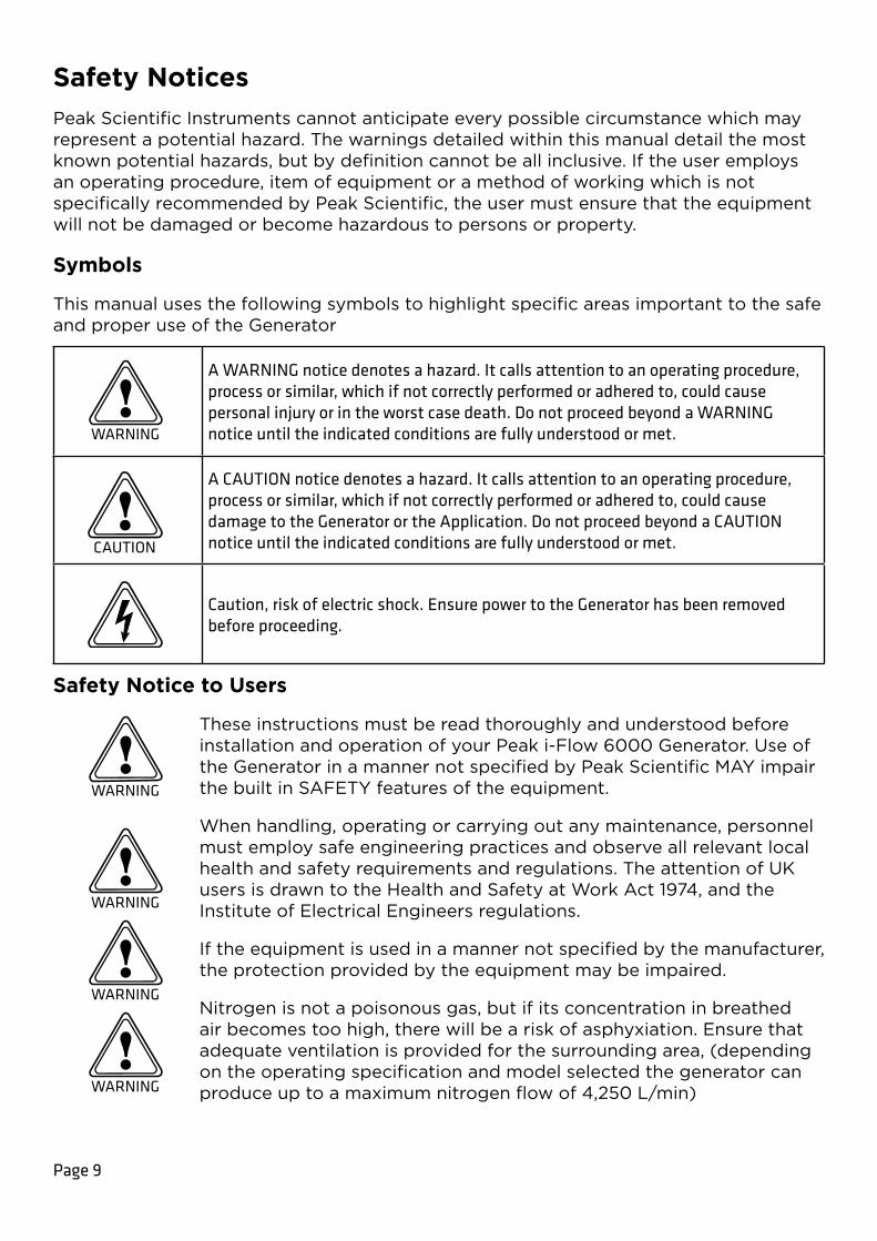
This manual uses the following symbols to highlight specific areas important to the safe and proper use of the Generator
A WARNING notice denotes a hazard. It calls attention to an operating procedure, process or similar, which if not correctly performed or adhered to, could cause personal injury or in the worst case death. Do not proceed beyond a WARNING notice until the indicated conditions are fully understood or met.
A CAUTION notice denotes a hazard. It calls attention to an operating procedure, process or similar, which if not correctly performed or adhered to, could cause damage to the Generator or the Application. Do not proceed beyond a CAUTION notice until the indicated conditions are fully understood or met.
Caution, risk of electric shock. Ensure power to the Generator has been removed before proceeding.
Safety Notice to Users
These instructions must be read thoroughly and understood before installation and operation of your Peak i-Flow 6000 Generator. Use of the Generator in a manner not specified by Peak Scientific MAY impair the built in SAFETY features of the equipment.
When handling, operating or carrying out any maintenance, personnel must employ safe engineering practices and observe all relevant local health and safety requirements and regulations. The attention of UK users is drawn to the Health and Safety at Work Act 1974, and the Institute of Electrical Engineers regulations.
If the equipment is used in a manner not specified by the manufacturer, the protection provided by the equipment may be impaired.
Nitrogen is not a poisonous gas, but if its concentration in breathed air becomes too high, there will be a risk of asphyxiation. Ensure that adequate ventilation is provided for the surrounding area, (depending on the operating specification and model selected the generator can produce up to a maximum nitrogen flow of 4,250 L/min)

No. 4 EU PED DOCEU Declaration of Conformity
We Peak Scientific Instruments Ltd.
Of Fountain Crescent, Inchinnan, Renfrewshire, PA4 9RE
Hereby declare that, this declaration of conformity is issued under the sole responsibility of the manufacturer.
Equipment: Pressure Swing Adsorption Gas Generator
Models: i-Flow 6000 Series & i-Flow O2 8000 Series
PED Module B Certificate No : CE 608102
PED Module D Certificate No : CE 608103
Pressure assembly consisting of the following key parts :
Piping Spec or Description Fluid PhasePED Hazard Cat.
Quality ModuleFluid Chart Cat
08-0700 CMS Assemblies 08-0700 CMS Assemblies (1 to 10 Model Dependant)(1 to 10 Model Dependant) Air/NAir/N22 GasGas 2G2G 22 IIII B+DB+D
3303560 Sieve Assemblies 3303560 Sieve Assemblies (1 to 6 model dependent)(1 to 6 model dependent) Air/0Air/022 GasGas 1G1G 11 IIII B+DB+D
Output Pressure Relief ValveOutput Pressure Relief Valve Air/NAir/N22/O/O22 GasGas 2G/1G2G/1G 2/12/1 IVIV B+DB+D
Front End Control Cabinet inc. associated valves & pipingFront End Control Cabinet inc. associated valves & piping Air/NAir/N22/O/O22 GasGas 2G/1G2G/1G 2/12/1 SEPSEP Not ApplicableNot Applicable
To which this declaration relates, is in conformity with the following applicable EU Directives, harmonized standards, and other normative requirements.
• Low Voltage Directive 2014/35/EU EN 61010-1: 2010 Safety Requirements for Electrical Equipment for Measurement, Control and Laboratory Use.
• Electromagnetic Compatibility Directive 2014/30/EU EN 61326-1: 2013 Electrical Equipment for Measurement, Control and Laboratory Use – EMC Requirements. (Class A)
• Restriction on the use of certain hazardous substances in electronic equipment (RoHS) Directive 2011/65/EU as amended by EU 2015/863.
• FCC 47 CFR Part 15 class A Unintentional radiators; Conducted and Radiated emissions limits.
Name and address of Notified body conducting the PED conformity assessment :
BSI Group The Netherlands B.V.Say Building, John M Keynesplein 9,1066 EP , Amsterdam,NetherlandsEC Number - 2797
Signed for and on behalf of Peak Scientific by
Signed:
Name: Fraser Dunn
Position: Design Engineering Manager
Peak Scientific Instruments ltd,
Inchinnan, Renfrew, Scotland, PA4 9RE, UK.
Date: 30th Novermber 2021

No. 5 UK PED DOCUK Declaration of Conformity
We Peak Scientific Instruments Ltd.
Of Fountain Crescent, Inchinnan, Renfrewshire, PA4 9RE
Hereby declare that, this declaration of conformity is issued under the sole responsibility of the manufacturer.
Equipment: Pressure Swing Adsorption Gas Generator
Models: i-Flow 6000 Series & i-Flow O2 8000 Series
PED Module B Certificate No : UKCA 753392
PED Module D Certificate No : UKCA 753395
Pressure assembly consisting of the following key parts :
Piping Spec or Description Fluid PhasePED Hazard Cat.
Quality ModuleFluid Chart Cat
08-0700 CMS Assemblies 08-0700 CMS Assemblies (1 to 10 Model Dependant)(1 to 10 Model Dependant) Air/NAir/N22 GasGas 2G2G 22 IIII B+DB+D
3303560 Sieve Assemblies 3303560 Sieve Assemblies (1 to 6 model dependent)(1 to 6 model dependent) Air/0Air/022 GasGas 1G1G 11 IIII B+DB+D
Output Pressure Relief ValveOutput Pressure Relief Valve Air/NAir/N22/O/O22 GasGas 2G/1G2G/1G 2/12/1 IVIV B+DB+D
Front End Control Cabinet inc. associated valves & pipingFront End Control Cabinet inc. associated valves & piping Air/NAir/N22/O/O22 GasGas 2G/1G2G/1G 2/12/1 SEPSEP Not ApplicableNot Applicable
To which this declaration relates, is in conformity with the following applicable EU Directives, harmonized standards, and other normative requirements.
• Low Voltage Directive 2014/35/EU EN 61010-1: 2010 Safety Requirements for Electrical Equipment for Measurement, Control and Laboratory Use.
• Electromagnetic Compatibility Directive 2014/30/EU EN 61326-1: 2013 Electrical Equipment for Measurement, Control and Laboratory Use – EMC Requirements. (Class A)
• Restriction on the use of certain hazardous substances in electronic equipment (RoHS) Directive 2011/65/EU as amended by EU 2015/863.
• FCC 47 CFR Part 15 class A Unintentional radiators; Conducted and Radiated emissions limits.
Name and address of Notified body conducting the PED conformity assessment :
BSI Group The Netherlands B.V.Say Building, John M Keynesplein 9,1066 EP , Amsterdam,NetherlandsEC Number - 2797
Signed for and on behalf of Peak Scientific by
Signed:
Name: Fraser Dunn
Position: Design Engineering Manager
Peak Scientific Instruments ltd,
Inchinnan, Renfrew, Scotland, PA4 9RE, UK.
Date: 30th Novermber 2021

No. 6 EU PED DOCWEEE Compliance Statement
The Waste Electrical and Electronic Equipment (WEEE) Regulations SI 2013 No 3113 and or the Waste Electrical and Electronic Equipment (WEEE) Directive 2012/19/EU apply to all electrical and electronic equipment placed on the market in the UK and EU covered by the scope of regulations which can be found in the Government Guidance Notes (PDF) produced by the Department for Business Innovation and skills for the UK and here for Europe.
All PEAK products that are subject to the WEEE directive are compliant with the WEEE marking requirement. Such products are marked with the “crossed-out wheelie bin” symbol (shown below) in accordance with European standard EN50419. All old electrical equipment can be recycled. Please do not dispose of any electrical equipment (including those marked with this symbol) in general rubbish bins. Please contact your dealer or distributor for clarity.

Page 13
Technical SpecificationEnvironment
Minimum Operating Ambient Temperature +5°C (41°F)Maximum Operating Ambient Temperature +50°C (122°F)Maximum Altitude 2000mMaximum Relative Humidity 80% non-condensing
When taken out of storage, the Generator should be allowed to acclimatize at room temperature for a minimum of 3 hours before operation.
Compressed Air Supply
Depending on your specific application, the pressure and flow required from the compressed air supply to the generator will vary. For your specific requirements please refer to your quotation documents, or contact Peak Gas Generation for further information. However all installations must meet the following conditions:
Minimum Air Quality IS0 8573-1:2010 class 1.4.1 or 1.2.1†Minimum Inlet Air Pressure 87 psig (6barg)Maximum Inlet Air Pressure 145 psig (10barg)Minimum Inlet Air Temperature +5°C (41°F)Maximum Inlet Air Temperature +35°C (95°F)
If you are in any doubt over the quality of your inlet compressed air DO NOT CONNECT to the generator, and contact Peak Gas Generation or the Peak Partner from which you purchased your Generator. Peak Gas Generation can offer a full range of compressors and air preparation equipment if required, which can be backed up by our global service support network.
It is the User / Installer’s responsibility to ensure the generator is connected to a suitably rated air supply, the air supply must also provide suitable protection to prevent over pressurization of the Nitrogen Gas Generator.
Electrical Requirements
Voltage 100 - 240 VAC ±10%Frequency 50/60 HzCurrent 2.0 – 1.0 AInput connection C20 PlugPower cord (Supplied) C19 socket to local connectionPollution degree 2Installation category Class I Protection Transient Overvoltage Category II
WARNING

Page 14
General
Model 601* 602* 603* 604* 605*Width mm(in) 500 (19.68)Height mm(in) 1738 (68.42)Depth mm(in) 760(29.92) 920(36.22) 1080(42.52) 1240(48.82) 1400(55.12)Weight kg(lbs) 197(433) 282(620) 367(807) 452(994) 537(1181)Shipping weight kg(lbs) 277(609) 364(801) 451(992) 538(1184) 625(1375)Noise level 59 dBA @ 1m
Model 606* 607* 608* 609* 610*Width mm(in) 500 (19.68)Height mm(in) 1738 (68.42)Depth mm(in) 1560(61.42) 1720(67.72) 1880(74.02) 2040(80.31) 2200(86.61)Weight kg(lbs) 622(1368) 707(1555) 792(1742) 877(1929) 962(2116)Shipping weight kg(lbs) 712(1566) 799(1758) 886(1949) 973(2141) 1060(2332)Noise level 59 dBA @ 1m
† (NOTE: Selection is application dependent – please confirm suitability via your local technical specialist).

Page 15
UnpackingAlthough Peak Gas Generation takes every precaution with safe transit and packaging, it is advisable to fully inspect the unit for any sign of transit damage.
Check ‘SHOCKWATCH’ and ‘TIP-N-TELL’ labels for signs of rough handling prior to unpacking.
Any damage should be reported immediately to the carrier and Peak Gas Generation or the Peak Partner from where the unit was purchased.
Page 15

Page 16
InstallationIt is the user/installer’s responsibility to ensure that the generator is located and protected against any external influences such as vibration, shock, wind, snow loading, earthquake or fire. The installation should conform to all local regulations and should be leak tight and completed by technically competent personnel.
Final Location of the generator should be carefully considered, the largest model in the range will weigh 1060 kg / 2332 lbs. Equipment is only to be installed on floor with a weight rating of min 1000kg/m2 or 200 lbs per Sq.ft.
Once in position the foot plate of the generator should be secured to the floor with fixings suitable to the materials of construction of the floor. 13mm diameter holes are provided adjacent to the levelling bolts to allow the unit to be fixed to the floor. Depending on the generator model you will have 4 or 8 fixing positions. Typically 10mm or 3/8” floor fixings approx. 75mm or 3” in length will be suitable on most concrete floors.
Generator EnvironmentThe Generator is designed for indoor use only. It should be installed adjacent to the application it is supplying. If this is not convenient then the unit can be sited elsewhere, however, consideration should be made of the lengths of pipe runs as pressure drops can result from extended runs of pipe.
Consideration should be given to the location of the generator to ensure it is protected from extreme fluctuations in ambient temperature. Ensure that adequate ventilation is provided for the surrounding area, (depending on the operating specification and model selected the generator can produce up to a maximum flow of 4,250 L/min). Installation in a confined space or poorly ventilated space is not recommended, however if you choose to do so ambient oxygen monitoring equipment is recommended.
WARNING
WARNING
CAUTION

Page 17
Generator General Dimensions
Note: Each additional bank assembly = 160mm / 6.3”
The Generator must always be placed on a level surface. Failure to do so
will affect the stability of the Generator.
2200 mm / 86.6”
1738
mm
/ 6
8.4
”
WARNING
760 mm / 29.9”500 mm / 19.7”

Page 18
Inlet / Outlet ConnectionsAll of the Generator output ports are located on the output panel on the Left hand side of the Generator. See below for recommended piping layout.
Unit Controls
Power Inlet
Nitrogen Output¾” BSP
Air Inlet 1” BSP
Tank Supply¾” BSP
Tank Return¾” BSP
Pressure GaugePressure Gauge
Control Screen
Pressure GaugePressure GaugePower SwitchEco mode LEDService LED

Page 19
Compressed Air QualityThe i-Flow 6000 Generator is an air purification system, it does not generate any gas pressure. Gas pressure is created and supplied to the generator by the user’s compressed air system. It is the user / installer’s responsibility to ensure that all components connected to the gas generator comply with local health and safety regulations and that the compressed air system is suitably protected from over pressure, including appropriately sized safety relief devices for both the compressed air and nitrogen process tanks.
No pressure greater than 10 barg should be applied to the inlet of the iFlow product.
The i-Flow 6000 Generator will typically be the last stage in a complete air compression and filtration system, the inlet air quality must meet a minimum of IS0 8573-1:2010 class 1.2.1. Class 1.2.1. is further defined as:
Class 1 – Particulate Per cubic meter of air the particulate count should not exceed 20,000 particles in the 0.1 to 0.5 micron range, 400 particles in the 0.5 to 1 micron range and 10 particles in the 1 to 5 micron range.
Class 2 – WaterA minimum pressure dewpoint (PDP) of -40°degC (-40°degF) is required, no liquid water is permitted.
Class 1 – OilPer cubic meter of air the maximum permissible oil content is 0.01mg, total level for liquid, aerosol and vapor.
A typical installation will consist of the following items:
• Oil Lubricated Screw – Air Compressor
• Compressed Air Storage Tank (with automatic condensate drain)
• Water Separator
• Pre-filter
• Active Carbon Filter
• Line Air Regulator
• Desiccant Air Dryer
• Dust Filter
• Active Carbon Tower
• Dust Filter
• i-Flow 6000 Series Nitrogen Generator
• Nitrogen Process Gas Tank
WARNING

Page 20
Sizing of all components in this line will have a critical effect on the performance of the Nitrogen Gas Generator, in particular the Nitrogen process Gas Tank. Please refer to your quotation documents for details of the items we have recommended to meet your specific requirements. Should you require any further assistance or support please do not hesitate to contact Peak Gas Generation or the Peak Partner from which you purchased your Generator. A full installation and commissioning service can be provided through the Peak Global Service network.

Page 21
WARNING
Electrical ConnectionConnect the Generator to a single-phase AC voltage supply using the power cord provided. The generator is fitted with an internal transformer that can accept any supply from 100 to 240 volts AC. If the appropriate power cord is not supplied; a new plug, rated to at least 5 amps, can be fitted by a qualified electrician.
DO NOT USE inadequately rated detachable Mains cords.
This unit is classified as SAFETY CLASS 1. THIS UNIT MUST BE EARTHED. Before connecting the unit to the mains supply, please check the information on the serial plate. The mains supply must be of the stated AC voltage and frequency.
EARTH/GROUND (E):- Green & Yellow or Green
LIVE (L):- Brown or Black
Neutral (N):- Blue or White
If the equipment is used in a manner not specified by the manufacturer, the protection provided by the equipment maybe impaired.
WARNING

Page 22
Recommended Piping LayoutTo allow proper operation and commissioning of the generator it is important to include bypass valves at the generator inlet / nitrogen outlet of the system. It is also recommended that a non-return valve be fitted on the exit of the system to prevent downstream pressure from returning to the system and damaging the generator. Please see below for recommended piping layout.

Page 23
Commissioning & Safe Start-Up SequenceWith reference to the diagram in the Recommended Piping Layout section.
Once the generator has been installed, DO NOT Switch on the power immediately. It is recommended that the inlet compressed air supply valve (1) remains closed, and that the inlet bypass valve (2) is opened slightly to sufficiently allow the inlet compressed air to vent and purge any remaining moisture from the newly installed pipework (if this is the first operation of the compressed air supply, it is recommended that the air be vented for a minimum of 2hrs to allow the air filtration and dryer to stabilise).
Once the inlet pipework has been purged, the inlet bypass valve (2) can then be closed and the pressure gradually introduced to the generator by slowly opening the compressed air inlet (1) valve. The outlet bypass valve (3) should now be open to atmosphere, and the delivery valve (4) to the customer application should be closed. Ensure that both Process Tank Isolation valves (5) are both fully open.
The power can then be turned on. On first start up air will be introduced to Column 1 and the front panel gauge will slowly start to rise. The front panel display will show a message “COLUMN 1” and a timer counting up. After approx. 30 to 80 seconds (timing will vary depending on your specific performance requirements) the front panel display will briefly show an “EQUALIZING” message and the pressure on Column 1 and 2 gauges should level out. Column 1 will then vent rapidly to zero and column 2 will continue to rise slowly. During this process the TANK pressure gauge should continue to slowly rise. Allow the Nitrogen Process Gas Tank to reach pressure, then continue to vent the outlet gas through the bypass valve (3) for a minimum of 4 hours (ideally this should be done overnight to fully purge all the remaining oxygen/moisture in the system).
The Generator has been pre-set in the factory to give the specified output flow-rate and pressure. Failure to achieve the factory specification after maintenance may be as a result of an incorrect service procedure, please review any maintenance carried out. If unable to achieve specification contact Peak Gas Generation for further assistance. After this time the outlet bypass valve (3) can be closed, and the delivery valve (4) to the customer application should be slowly opened to pressurize the line.
The design of the generator is that it will deliver up to your specific output pressure and flow of nitrogen. Should the demand for Nitrogen be less than the rated output flow, or indeed should the demand stop the generator will automatically go into ECO Mode and the front panel LED will illuminate. In ECO mode the changeover of the columns is suspended which will stop the consumption of inlet compressed air. The control system will automatically detect when the demand resumes and the generator will start to produce nitrogen again.

Page 24
Normal OperationThe i-Flow 6000 Gas Generator is designed specifically to minimize operator involvement. As long as the system is installed as described in earlier sections and is serviced in accordance with the specified maintenance recommendations (see Service Requirements), then it should simply be a matter of turning the Generator on. Note: the generator will only produce nitrogen gas based on demand, so should typically be left in a powered state, live compressed air supply. If the system is shutdown, or suffers a power failure, it will restart automatically. However, if left without inlet air pressure for a prolonged period and the Nitrogen Process tank is allowed to vent all pressure, then the commissioning process above should be repeated to purge the oxygen from the system before high quality nitrogen gas can be produced again.
The Generator will automatically produce the factory set flow and pressure.
Note: The side panels of the generator should not be removed during operation unless you have received training and are technically competent to manage the potential risks present. Located inside the cabinet are the vent silencers and safety relief valve, which periodically release gas at pressure and could cause injury.
Inspection plugs are located on the rear and top of the generator. These plugs must NOT be removed whilst the system is under pressure. If removed, it is likely that pressure will be released violently and cause injury.
Safe Isolation ProcessTo shut the system down, close the inlet air supply valve (1), BUT leave the electrical power on to the generator. Close the nitrogen outlet valve (4) to the application, and slowly open the bypass / commissioning valve (3) to allow the nitrogen product gas to vent to atmosphere. NOTE: do not isolate the Process Tank valves (5) as this will trap pressure in the tank. For the product to be completely safe to continue work, ALL pressure must be fully dissipated. Ensure ALL front panel gauges read zero before turning off the power on the front panel and removing the mains cord from the left hand side of the generator before proceeding. Note: Due to the nature of the Carbon Molecular Sieve it could take considerable time for the generator to release all the trapped oxygen. The bypass valve (3) should remain open at all times, allowing the CMS to release oxygen and pressure can build again if closed.
Once service operations have been completed, the generator can be re-connected to the mains supply and the Commissioning process described in earlier sections should be repeated.
Due to the simplicity of the design and the small number of moving parts the i-Flow 6000 Series Nitrogen Generators will have a long and trouble free life. However as with all scientific and technical equipment it should be regularly inspected and serviced as below.
WARNING
WARNING

Page 25
Service RequirementsService Schedule
Purchase Interval Component Part No.Quantity.
601*-605* 606*-610*
12 months
Vent Silencer Element 02-5710 2 4
Pneumatic Valve Exhaust Silencer 02-1016 5 7
N2 Supply NRV 02-5620 2 2
48 months
O2 Analyser %* 04-4571 1 1
O2 Analyser PPM* 04-4572 1 1
*Analyzer service is dependent on selected model.

Page 26
Peak ProtectedWith Peak Gas Generation you invest in not only a product but peace of mind. With a network of certified Peak engineers stationed throughout the globe, Peak’s rapid response team are never far away and our commitment is to keep your generator running day in, day out, protecting your productivity.
[Peak Protected] can provide…
Installation A dedicated Peak engineer will visit
your site to install and setup your generator
IQ/OQCertified assurance for applications requiring documented qualification
Complete planSwift response by a Peak Service
Engineer within 72 hours & planned preventative maintenance
SparesGenuine Peak parts with express
delivery, ensuring optimal performance and lifetime
Premium ProtectedGuaranteed rapid on-site response
within 24 hours & planned preventative maintenance
Technical Support HotlineAround the clock support by phone or online with our global technical
helpdesk
To find out more about protecting your investment visit: www.peakscientific.com/protected

Page 27
CleaningClean the outside of the Generator only using warm soapy water and a clean damp cloth. Ensure the cloth is thoroughly rung out to remove excess fluid prior to use. Do not use decontamination or cleaning agents that could cause a HAZARD as a result of a reaction with parts of the Generator or material contained within it. If there is any doubt about the compatibility of decontamination or cleaning agents please contact your Peak Gas Generation representative.
Cleaning should only be undertaken with the power switched off and the power cord removed from the rear of the generator.
Under no circumstances should any solvents or abrasive cleaning solutions be used as these can contain fumes that could be harmful to the generator.
Care should be taken with Leak Detections Liquids.
CAUTION
CAUTION

Page 28
Go Online or Complete and ReturnYou can register for your FREE 12 month Warranty with ease online at www.peakscientific/protected.
Alternatively, you can send the completed form to Peak Scientific by post or email at [email protected].
Product Warranty RegistrationContact name
Email address
Company
Address
City/town
Postcode
Country
Telephone
serial #
Model type
Installation date
Do you still use an alternative gas solution i.e. cylinders or bulk liquid?
Yes No
What gas requirements do you have in your lab? Hydrogen Nitrogen Zero Air
Extend your cover withPeak Scientific offer comprehensive gas after sales support packages. Peak [Protected] aftercare support can guarantee an on-site response within 72 hours*, genuine parts from our ISO9001 approved factory and a 95% first-time fix rate. See our enclosed Peak [Protected] leaflet for further information.
Important!You have 1 month to register your Peak Scientific product from the date of installation. Once registered the warranty will be honoured for a period of 12 months. If you wish to defer the installation of your , you must notify Peak Scientific immediately by emailing [email protected]. For s that remain unregistered after 1 month from the shipment date, the warranty will be considered active from the date of factory dispatch.
* Complete Plan only
Go Online or Complete and ReturnWe know that registering any of your recently purchased products is not the first thing on your mind- but it is very important to both of us. Not all warranties are alike and Peak Gas Generation stand out against other gas suppliers as we offer a comprehensive, quick response, on-site warranty. This means that in the very unlikely case that your gas develops a fault we have rapid support teams on-hand around the world who are able to come to your lab and get you back up and running in no time.
Register for your comprehensive 12 month on-site warranty with ease online at www.peakscientific.com/protected.
Alternatively, you can send the completed form to Peak Gas Generation by post or email at [email protected].
Important!You have 1 month to register your Peak Gas Generation product from the date of installation. Once registered the warranty will be honoured for a period of 12 months. If you wish to defer the installation of your generator, you must notify Peak Gas Generation immediately by emailing [email protected]. For generators that remain unregistered after 1 month from the shipment date, the warranty will be considered active from the date of factory dispatch.

CSA Compliance Statement
CSA Group (Canadian Standards Authority) is a Nationally Recognised Testing Laboratory (NRTL), headquartered in Toronto Canada.
They are authorised to evaluate product to both their own and Underwriters Laboratory (UL) standards and certify the product to be in compliance to the relevant standards.
Peak products are certified to the current in force revision of the following standards in order to cover both Canadian and United States requirements for “Safety Requirements for Electrical Equipment for Measurement, Control and Laboratory use, Part 1: general Requirements”.
Canada: CAN/CSA C22.2 No 61010-1-12
United States: UL 61010-1
As a result the products covered by this statement are certified and listed by CSA accordingly and are entitled to carry the CSA mark with both Canadian and United States subscripts , as shown below on the product rating label.

Peak Gas Generation gas generators define the benchmark in reliability, convenience and performance in facilities around the world, and come backed by a 12 month on-site warranty. Beyond this period how-ever you can ensure that your investment continues to be [Protected] by our comprehensive generator care cover.
Our world-class aftercare support packages deliver a program of scheduled preventative maintenance whilst giving you the reassurance of instant access to worldwide technical support and priority on-site
response in the untimely event of a breakdown.
For further information on any of our generator products please contact [email protected]
Peak Gas GenerationFountain CrescentInchinnan Business ParkInchinnanPA4 9REScotland, UKTel: +44 141 812 8100Fax: +44 141 812 8200
Copyright © Peak Scientific Instruments Ltd 2021 — i-Flow 6000 Series User Manual Rev 15 RSID 175 PN UM00018 EN copy —30/11/2021